12 minute read
Le transizioni tra sistemi di ritenuta con analisi ad elementi finiti


segnaletica &sicurezza
LE TRANSIZIONI TRA SISTEMI DI RITENUTA
Advertisement
CON ANALISI AD ELEMENTI FINITI
LE TRANSIZIONI TRA SISTEMI DI RITENUTA STRADALE SONO UN ELEMENTO FONDAMENTALE PER GARANTIRE LA SICUREZZA DEI TRASPORTI SU STRADA E DEL TRAFFICO VEICOLARE. TALI COMPONENTI SONO, OGGI, PROGETTATI E VERIFICATI EFFICACEMENTE MEDIANTE SIMULAZIONI AGLI ELEMENTI FINITI, METODOLOGIA ALLO STATO DELL’ARTE GIÀ AMPIAMENTE UTILIZZATA PER LA RISOLUZIONE DI PROBLEMATICHE STRUTTURALI
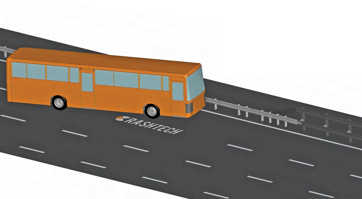
L’iter di studio dei sistemi di ritenuta stradale non termina con i test sperimentali di certificazione ma deve proseguire anche dopo l’ottenimento del marchio CE, per consentire una corretta ed efficace valutazione degli aspetti operativi, ad esempio relativi a singole installazioni, all’interazione dei sistemi di ritenuta con infrastrutture esistenti o al loro collegamento attraverso una transizione. La Normativa ENV 1317-4:2002 definisce transizione “un elemento da interporre tra due barriere di sicurezza aventi diversa sezione trasversale o differente rigidità laterale, affinché sia garantito un contenimento continuo”. Per transizione si intende quindi quell’elemento di collegamento tra due sistemi di ritenuta stradale, aventi differente sezione trasversale o diversa rigidezza laterale, con il compito di garantire una connessione efficace e una variazione graduale di rigidezza e di contenimento tra gli stessi. Gli aspetti relativi alle transizioni, dal punto di vista normativo, sono trattati nel documento ENV 1317-4:2002 e successive bozze di modifica, tuttora in via di aggiornamento all’interno della revisione globale della Norma EN 1317. Nella documentazione tecnica più recente, per la verifica delle transizioni sono previste diverse metodologie che comprendono, in alternativa, test sperimentali full scale o simulazioni agli elementi finiti. In linea generale, una transizione tra due barriere di sicurezza deve essere in grado di garantire sia il contenimento del veicolo in svio, considerando un mezzo rappresentativo della barriera di classe inferiore, sia il raggiungimento di un indice di severità accettabile in caso di impatto con veicolo leggero. Ad esempio, nel caso di una transizione tra una barriera di classe H2 e una
TRANSITIONS BETWEEN ROAD RESTRAINT SYSTEMS
THROUGH FINITE ELEMENT ANALYSES
TRANSITIONS BETWEEN ROAD RESTRAINT SYSTEMS ARE A FUNDAMENTAL ELEMENT TO GUARANTEE THE SAFETY OF ROAD TRANSPORT AND OF VEHICULAR TRAFFIC. NOWADAYS, TRANSITIONS ARE EFFECTIVELY DESIGNED AND VERIFIED THROUGH FINITE ELEMENT SIMULATIONS, A STATE-OF-THE-ART METHODOLOGY ALREADY WIDELY USED IN THE SOLUTION OF STRUCTURAL PROBLEMS
The study and analysis process of the road restraint systems is not concluded by the certification experimental tests, such process shall continue, even after obtaining the CE marking, to allow for a correct and effective evaluation of operative aspects, for example regarding single installations, the possible interaction of road restraint systems with existing structures or their connection through a transition element.
SISTEMI DI RITENUTA
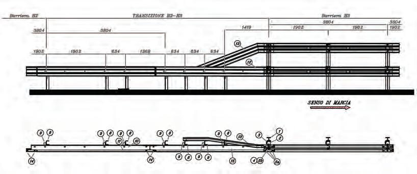
1. La transizione diretta dalla barriera H2 alla barriera H3 1. Transition from the H2 barrier toward the H3 barrier
barriera di classe H3, tale transizione deve essere verificata con un impatto TB51 (bus da 13.000 kg), test di contenimento previsto per la barriera di classe H2, e con un impatto TB11 (auto da 900 kg), test di severità previsto per entrambe le classi di barriera di sicurezza. La verifica viene svolta impattando il sistema di ritenuta con veicoli conformi alle richieste della EN 1317 in termini di massa, geometria e velocità, interagendo con la transizione dal sistema di ritenuta più deformabile in direzione di quello meno deformabile, quindi generalmente dalla barriera di classe inferiore verso quella di classe superiore. La definizione dei punti di impatto, suggerita nella documentazione tecnica, ha l’obiettivo di individuare le zone più critiche per la verifica del contenimento del veicolo pesante e della severità d’impatto sul veicolo leggero. Rimane in capo al Progettista della transizione e/o al laboratorio prove la definizione di altri punti di impatto ritenuti critici per la transizione in esame. Se ritenuto necessario, anche se generalmente meno critico, è possibile valutare il comportamento della transizione anche in direzione opposta, ossia impattando il sistema dalla barriera meno deformabile verso quella più deformabile. Vista l’ampia esperienza maturata nello studio dei sistemi di ritenuta stradale, CrashTech si occupa anche della progettazione e verifica delle transizioni tra diverse barriere di sicurezza, avvalendosi delle simulazioni numeriche ad elementi finiti (FEM). Le simulazioni ad elementi finiti, utilizzate per lo studio e la verifica dei sistemi di ritenuta stradale, sono lo strumento allo stato dell’arte per l’analisi di strutture complesse sollecitate in condizioni dinamiche. Nel caso specifico, gli elementi finiti consentono lo sviluppo e la valutazione della transizione tra due sistemi di ritenuta stradale, permettendone lo studio del funzionamento in diversi scenari di impatto, approccio che risulterebbe oneroso sia in termini di tempi sia di costi se affrontato per via prettamente sperimentale. L’analisi tramite FEM consente inoltre la valutazione di aspetti di dettaglio della transizione come, ad esempio, gli elementi di collegamento tra i due sistemi di ritenuta e le soluzioni tecniche individuate per terminare componenti potenzialmente critici. La validità delle analisi numeriche sviluppate è verificata attraverso le linee guida della Normativa di riferimento per la meccanica computazionale, EN 16303, amIn the ENV 1317-4:2002 Standard, the definition of transition is “so that interface between two safety barriers of different cross section or different lateral stiffness, the containment is continuous”. Therefore a transition is a connection element between two different road restraint systems (different cross section or lateral stiffness), with the aim of realizing an effective connection and a gradual variation of stiffness and containment between them. The aspects regarding transitions, from a normative point of view, are debated in the ENV 13174:2002 document and its successive draft versions, currently being updated in the frame of the global revision of the EN 1317 Standard. In the more recent technical documentation, different methods are considered for the assessment of transitions, mainly based on experimental full scale crash tests or, alternatively, on finite element simulations. From a general perspective, a transition between two road safety barriers shall guarantee the containment of an errant vehicle, considering the heavy vehicle used for the certification of the lower containment level barrier, and an acceptable severity in case of impact with a light car. For example, for a transition between two barriers with containment levels H2 and H3, the assessment of the transition performance shall be done with a TB51 impact (13.000 kg bus), which is the containment test prescribed for the H2 barrier, and with a TB11 crash (900 kg car), which is the severity test prescribed for both H2 and H3 barriers. The assessment is done impacting the system with vehicles in compliance with the requirements of the EN 1317 Standard in terms of mass, geometry and velocity. The transition is evaluated with an impact direction from the softer to the stiffer barrier, therefore generally from the lower containment barrier toward the higher containment barrier. The impact points, suggested by the technical documentation, are selected with the aim of identifying the most critical areas for the assessment of the heavy vehicle containment and of the impact severity on the light car. The identification of other impact points for the transition in question, if they are considered critical, is left to the transition designer or to the test laboratory. If deemed necessary, even if usually less critical, the transition performance can also be evaluated considering the opposite direction, with the vehicle impacting the system from the stiffer toward the softer barrier. Thanks to the experience gained in years of activities on road restraint systems, CrashTech also deals with the design and the performance assessment of transitions between road safety barriers, taking advantage of the finite element simulation method (FEM). The finite element simulations, which are used to study and
segnaletica &sicurezza
piamente utilizzata per la validazione dei modelli numerici dei sistemi di ritenuta stradale. A titolo d’esempio, si riporta in Figura 1 il disegno di una transizione sviluppata tra due barriere di sicurezza, di classe H2 e H3. Nel caso specifico, anche se non strettamente necessario, lo studio della transizione è stato svolto con modelli numerici validati (secondo la Norma EN 16303) delle due barriere in esame, disponibili poiché precedentemente sviluppati proprio allo scopo di essere utilizzabili per successive analisi applicative. Come mostrato in Figura 2, i modelli a elementi finiti descrivono in maniera dettagliata la struttura in esame così da poter evidenziare, nel corso del fenomeno di impatto, l’insorgenza di eventuali cedimenti o criticità legate alla particolare geometria della transizione. Nello specifico, nei modelli numerici le connessioni tra le parti sono state riprodotte con elementi solidi precaricati, così da modellare il reale stato di accoppiamento tra i componenti ed essere in grado di descrivere eventuali cedimenti per rifollamento delle lamiere. Per la corretta descrizione del comportamento dei materiali metallici, si sono inoltre utilizzati una legge costitutiva elastoplastica ed un algoritmo di rottura appositamente sviluppato, in grado di descrivere efficacemente le zone di cedimento anche quando sottoposte a stati di sforzo complessi. Una transizione è sviluppata partendo da una prima fase di progettazione principalmente basata su criteri geometrici, a valle della quale viene realizzata la sua controparte numerica ad elementi finiti. Generalmente, una volta identificati i punti di maggiore criticità della transizione, sono svolte le prime analisi numeriche, per la verifica della capacità di contenimento del sistema. Per analisi successive si identificano eventuali criticità legate al design preliminare sino al raggiungimento di una configurazione di transizione efficace sia in termini di contenimento, con il veicolo pesante, sia in termini di severità, con il veicolo leggero. Nel caso specifico, la configurazione di Figura 2 è stata analizzata, secondo la direzione generalmente più critica (da barriera H2 a barriera H3), mediante due impatti di tipo TB51, per verificare il contenimento del sistema, e un impatto di tipo TB11, per verificarne la severità. Inoltre, al fine di valutare il comportamento della transizione anche nel caso venga impattata in direzione opposta, è stata svolta un’ulteriore simulazione per la verifica del contenimento tramite test TB51, con veicolo diretto dalla barriera H3 verso la barriera H2. Si riporta a titolo d’esempio, in Figura 3, la simulazione di uno dei test d’impatto TB51. Le analisi numeriche svolte hanno consentito di verificare il design della transizione, in entrambe le direzioni di marcia, evidenziando l’efficacia della soluzione studiata in diversi scenari di impatto. L’attività di studio delle transizioni tramite modelli agli elementi finiti consente di valutare in maniera oggettiva l’efficacia di una soluzione progettuale evidenziando e risolvendo, nel corso delle analisi numeriche di sviluppo, eventuali criticità spesso non desumibili senza l’ausilio di strumenti di analisi di dettaglio, quali le simulazioni strutturali d’impatto. n
(1) Ingegnere Aeronautico, Professore del Politecnico di Milano (2) Ingegnere Aeronautico, Analista Strutturale di CrashTech Srl evaluate road restraint systems, are the state-of-the art tool for the analysis of complex structures under dynamic loads. In the specific case, finite element analyses can be effectively used to develop and to assess the transition between two road safety barriers, with the possibility to investigate the system behavior in different impact scenarios, while such approach would be difficult, in terms of times and costs, if only based on experimental tests. The finite element method also proves to be useful for the evaluation of the transition details as, for example, the connection elements between the road restraint systems or the technical solutions used to safely end the components of the system which could, otherwise, be hazardous. The accuracy of the numerical analyses is assessed following the guidelines of the reference Standard for computational mechanics, EN 16303, widely used for the validation of the road restraint systems numerical models. As an example, the drawing of a developed transition between two barriers, H2 and H3, is shown in Figure 1.
In this specific case, even if not strictly necessary, the development of the transition has been done using validated numerical models (in accordance with the EN 16303 Standard) of both the barriers, available because previously developed to be readily used in case of need. As shown in Figure 2, the finite element models reproduce the real counterparts in detail, to correctly provide indications of the possible onset of failures or critical aspects, due to the specific geometry of the transition. In particular, connections between parts, in the numerical models, have been discretized with preloaded solid elements, to reproduce the real coupling condition and the correct stress state and to reliably predict possible bearing failures of the metal sheets. To correctly describe the behavior of the metallic materials, an elastoplastic constitutive law has been used together with a specific failure algorithm, able to effectively identify failure areas even if characterized by complex stress states. A transition is developed starting with a first design phase mainly based on geometrical criteria, after which the finite element model of this initial configuration is realized. Generally, after the identification of the most critical points of the transition, the first numerical simulations are run to assess the containment capability of the system. Through consecutive numer-

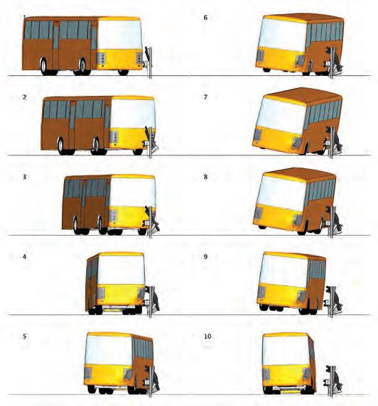
2. Un dettaglio della transizione da H2 ad H3 2. Detail of the transition from H2 to H3
3. La verifica del contenimento con simulazione del test TB51, transizione da H2 ad H3 3. Assessment of the containment level through a TB51 simulation, transition from H2 to H3 SISTEMI DI RITENUTA
ical analyses, possible critical aspects are identified and solved to obtain a final transition configuration which is effective in terms of containment, considering the heavy vehicle, and of severity, for the light car. In this specific case, the configuration shown in Figure 2 has been analyzed, considering the impact direction usually more critical (from the H2 barrier toward the H3 barrier), with 2 TB51 impacts, to verify the containment of the system, and 1 TB11 impact, to assess the severity level. Moreover, to check the behavior of the transition in case of impact in the opposite direction, an additional TB51 test has been simulated for the verification of the containment with the vehicle moving from the H3 barrier toward the H2 barrier. As an example, a TB51 impact simulation is shown in Figure 3. The numerical analyses have been useful to assess the transition design, considering both impact directions. The simulations have shown the effectiveness of the final transition configuration in different impact scenarios. The study of transitions with the finite element method allows for an objective evaluation of the specific design solution effectiveness, providing a useful instrument to highlight and solve, while running development simulations, possible critical aspects which would be hard to identify without a detailed tool as full-scale crash simulations are. n
(1) Aeronautical Engineer, Professor at Politecnico di Milano (2) Aeronautical Engineer, Structural Analyst at CrashTech Srl
Autoperforanti Sirive®
Le uniche barre autoperforanti qualificate in Italia in accordo con il DM 17/01/2018 (NTC 2018)
Supergabion Sirive®
Gabbioni rigidi a struttura reticolare modulare: l’evoluzione dei gabbioni

Ancoraggio Flottante Sirive®

Un freno alle frane: la soluzione per la stabilizzazione di frane lente in terra


