
29 minute read
ORGANIZATIONS AND INDIVIDUALS INVOLVED IN THE PRUITT-IGOE DYNAMIC TESTING PROJECT

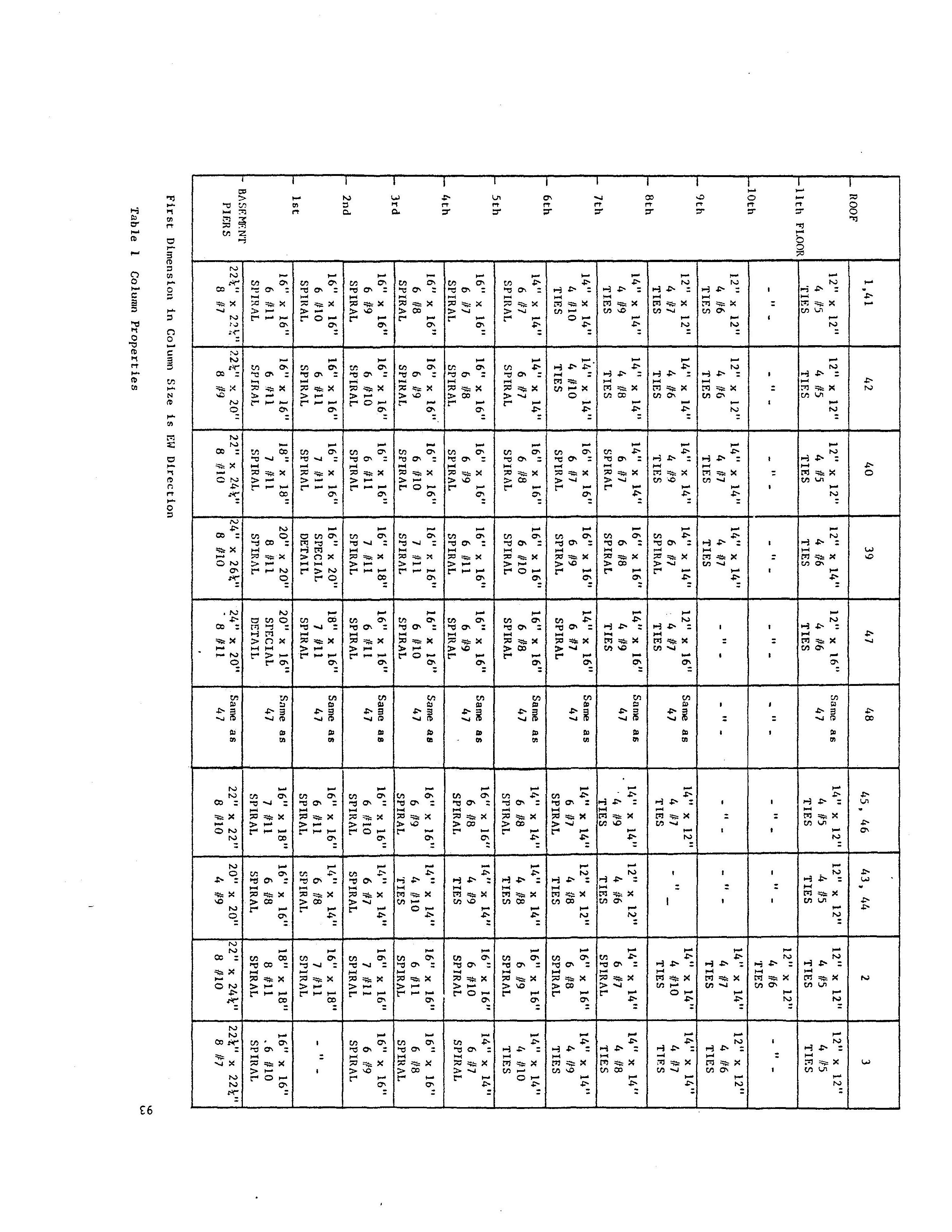
from Galambos and Mayes
by Straam Group
Many individuals and organizations helped make the project possible. Following is a list of the organizations and the people who were involved in one way 'or another with the work.
The National Science Foundation
Advertisement
The project was funded by the National Science Foundation for the total amount of $390,500 ($20,000 for the feasibility study and the remainder for the testing project). The technical direction during the proposal development and during the actual performance of the work was provided by Dr. John Scalzi, Program Manager in the Earthquake Engineering Division of the NSF.
The Principal Research Participants
The project was under the principal supervision of Dr. T. V. Galambos, who was responsible for the overall management and supervision of all phases of the work. Assisting him were his colleague at Washington University, Dr. David S. Hatcher, and Dr. Ronald L. Mayes from Computech, Berkeley, Dr Hatcher was in charge of the dimensional and material properties survey, and he assisted in the damage assessment during the large amplitude shaking tests. Dr. Mayes brought his considerable experience in dynamic testing to bear on the planning and execution of the small scale and the large scale dynamic tests, and he was responsible for the analysis, interpretation and the presentation of the dynamic data.
Washington University Administration
The responsible officials of Washington University are Dr. William H. Danforth, Chancellor, Mr. Edward L. MBcCordy, Associate Vice Chancellor for Research and Dr. James M. Dean of the School of Engineering and Applied Science. During the proposal writing phase Mrs. Blanche W. Jones, Sponsored Projects Associate, and Mrs. Idelle Hirsch, Director of Engineering Accounting, were of great assistance. The most valuable and day-to-day support was provided by Mr. MYron P. Mustaine, Sponsored Projects Administrator, who was particularly helpful in contract negotiations with NSF, Boeing, MCDonnell-Douglas and Applied Nucleonics. Dean MCKelvey was of great assistance in providing funds to tide the project over the period when the first allotment of the total funds had been used up and the final payment had not yet been received from NSF.
Many individuals in the University's Funds Accounting division were actively helpful in the day-to-day financial operations of the project.
Mr. David R. Armstrong of the Technical Services group of the School of Engineering served the project as photographer and film producer.
In the Civil Engineering Department the typing, phoning and the thousands of administrative and financial details were taken care of by Mrs. Lois R. Brown and Mrs. Alice J. B1etch.
Washington University Students and Staff
Three undergraduate upper level Civil Engineering Students served as overall workers: Ronald A. Gardiner, Elaine M. Gregory and James R. Vosper. These students worked unstinting1y in all kinds of weather on jobs ranging from knocking out walls with a sledge hammer to assisting in data taking. Their main effort consisted of the performance of the dimensional and material survey work which was done during July and August. They were helped from time-to-time as required by other students, especially during the mode-shape surveys.
Mr. Arthur Monsey, affiliate professor of Civil Engineering and a doctoral candidate, was of special value to the project because of his previous experience. At the time of the construction of the Pruitt-Igoe complex in the late 1950's he served as construction engineer for the contractor, the Millstone Construction Company, as supervisor of the work on these buildings. Mr. Monsey's experience with construction, management, planning and labor problems, as well as his intimate knowledge of the St. Louis construction, equipment and labor market, saved the project from countless difficulties.
St. Louis Housing Authority
This agency was the organization responsible for the Pruitt-Igoe Housing Complex, and it was through their cooperation and permission that the test-building was made available. We also received from them copies of the architectural drawings of the buildings. Mr. Thomas Costello is Executive Director of the St. Louis Housing Authority. Mr. Harry Dew, an engineer with the Authority, was of special help to the project in its initial phases. Applied Nucleonics Company, Inc.
The small-amplitude dynamic tests were performed by this Los Angeles based company specializing in performing analytical and experimental dynamic studies on various types of structures and structural components. The small amplitude tests were performed in the second week of July 1976, only about two weeks after we were permitted to enter the site. The team was supervised and managed by Dr. Paul Ibanez, and the other members of the team were Mr. Robert S. Keowen, Mr. William E. Gundy and Dr. Charles Kircher. These professional engineers, with the aid of the Washington
University workers and the Cleveland Wrecking Company crane, made the set-up, performed the required tests and disassembled the equipment in a record time of about three days. The Applied Nucleonics engineers showed exceptional competence not only in structural dynamics but also in making their intricate electronic equipment work without a hitch. They were extremely hard-working, and they delivered the results of their tests in a final report about two months later. The small-amplitude tests went extremely well, and the Applied Nucleonics engineers, especially Dr. Paul Ibanez, deserve special credit for their work. Credit goes also to Dr. Craig B. Smith and Mr. George B. Howard, administrative officers of the Company.
MCDonnell-Douglas Corporation
Engineers from the McDonnell-Douglas Aircraft Corporation were responsible for the data acquisition during the large-amplitude dynamic tests which were performed from mid-September to mid-October of 1976. Mr. Edward L. Smith, senior engineer, was in charge of the planning, installation, operation and disassembly of the instrumentation, and he was also responsible for data taking and data reduction. He was assisted by Mr. Lloyd D. Russell and Ralph T. Jensen. The data taking process worked extremely well and efficiently, thanks to the careful planning and the conscientious hard work of these individuals. They also installed a very efficient internal communications system. Administrative and technical support to the McDonnell-Douglas field crew was provided by many members of this organization, but especially by Messrs. Milton Hieken, Earl C. Stuckman, Jr.,
J. C. Bass.
By far the most difficult part of the whole project fell on the engineers of the Boeing Company who were responsible for the equipment which generated the large amplitude vibration. This work had never been done on this scale before, and it seemed doubtful to many that such a large building could be deflected at all with such large amplitudes. The equipment supplied by Boeing consisted of two major components: the mechanical-hydraulic-electrical device which produced the motion, and the auxilIary electronic control devices which kept it on course. Formidable difficulties were overcome in the first three weeks after the arrival of the Boeing team in mid-September, but by early October it was evident that the experiment was going to succeed. The difficulties and problems are described elsewhere in this report. It suffices here to make the statement that the Boeing engineers performed miracles with their equipment under very difficult conditions. No matter how badly things looked, they never gave up or despaired, just as if the word "impossible" was not in their vocabulary.
The Boeing field crew was headed by Mr. Jack Hess. The shakingmachine was designed, operated, assembled and repaired by Mr. Dexter Burlingame who was assisted by Mr. Willard I. Lathrop during the whole period of testing and also by Mr. J. D. King during the first two weeks of assembly. Mr. Burlingame showed unusual resourcefulness and ingenuity in the face of severe difficulties, and it is largely to his credit that the shaking machine performed its intended function. The electronic control system was installed and operated by Mr. David E. Marshall. In addition, Mr. Gene Eilenfeld spent considerable time on the project during the times when difficulties were encountered. Home-office technical and administrative support was given by Messrs. Thomas E. Miller, Peter D. Schenck, H. Morris Kilborn and P. C. Hill.
The greatest credit for the success of the project must go to the Boeing team; they showed much diligence, good sense, a calm outlook, great resourcefulness and boundless optimism.
The Cleveland Wrecking Company
The Cleveland Wrecking Company is a large Cincinnati-based demolition contractor which obtained the contract to remove the Pruitt-Igoe buildings.
To them, as well as to the St. Louis Housing Authority, our research project was essentially a nuisance with people in their way, possibly causing delays or even accidents. However, they did not feel that way about it, and they extended their most open cooperation. Mr. Marvin H. Rose, chairman of the board, visited my office in April 1976, and it was through his whole-hearted cooperation that the legal and insurance difficulties were removed and we could start the project.
The Cleveland Wrecking Company cleared the buildings around the test building away first, leaving an uncluttered open space around it; they repeatedly cleared the ground of rubble, they provided us a number of times with crane service, they removed the walls from the building after the E-W phase of shaking was completed, and they waited patiently for us to get done. The people from this company also helped with advice, they let us use their telephone, and through many courtesies made the work not only pleasant but also less expensive than originally expected.
The following members of the Cleveland Wrecking Company team on the Pruitt-Igoe demolition project were especially helpful: Mr. James B. Crane, Project Manager, Mr. T. B. Laws, project supervisor, and Mr. Morris Mitchell, office manager.
AALCO Wrecking Company of St. Louis
The AALCO Wrecking Company was the St. Louis-based collaborator with the Cleveland Wrecking Company in the Pruitt-Igoe demolition contract. Their officers shared in the help provided to us in the shaking project, especially through the friendly cooperation of the president of the company, Mr. M. Myron Hochman and his son, Mr. Daniel E. Hochman.
Night-Hawk Security Agency
Security on the test project was provided by the guards of the NightHawk Security Agency, Col. L. T. Martin, commander. The guards were always prompt, courteous and helpful, and throughout the project no equipment was missing, damaged or stolen. A very excellent job of guarding was done by this group.
Sachs Electric Company of St. Louis
Electrical lines for the motor-pump assembly and the instruments were installed, repaired, maintained and disassembled by the Sachs Electric Company under the supervision of Mr. Myron Hubenschmidt.
Other St. Louis Organizations
Various other organizations provided services for this project, or helped in some way towards its success:
Laclede Steel Company (reinforcing bars, Mr. David B. Neptune)
Collins and Herman, Inc. (fence around project, Mr. James W. Collins)
Pittsburgh Testing Laboratories (concrete cores)
Bell Telephone Company (temporary telephone service)
Union Electric Company (power service, Mr. William L. Waltke)
Wolfert Heavy Hauling and Erecting Co. (riggers, Mr. J. T. Keough)
The Wightman Agency (Insurance)
Millstone Construction Co. (Mr. I. E. Millstone, President)
City of St. Louis, Water Division
Real Estate Research Corporation (Mr. David E. Wuenscher)
Sverdrup and Parcel, Engineers and Architects
Individuals and Organizations Who Provided Advice
Mr. Ben Kacyra, Director, Earthquake Engineering Systems, San Francisco
Mr. Michael N. Salgo, Chairman, ASCE Research Council on Performance of Structures (RCPS)
Dr. James M. Fisher, advisor to the project, RCPS
Dr. V. Bertero, advisor to the project, University of California at Berkeley
Dr. Roger Scholl, advisor to the project, Blume Associates of San Francisco
Dr. Mark Fintel, PCA Laboratory, Chicago
Dr. William J. Hall, advisor to the project, University of Illinois
These individuals, through discussions and site visits, contributed of their time and their valuable advice.
Many thanks go to all of the above listed individuals in many organizations. In many different ways they made it possible that in a brief but intense five month period a large concrete building was made to shake and weave like a ship tossed on the sea. Grateful acknowledgment is here also given to Providence for the very favorable weather and for the fact that no one working on the site was injured.
Computech
Dr. Mayes was aided in the analysis of the dynamic data by his colleagues at Computech, Dr. Lindsay R. Jones, Dr. Jehlery P. Hollings, Mr. Martin Button and Mr. Mark Skinner. Dr. James L. Beck of the California Institute of Technology was responsible for the development of the computer program that was used to obtain the damping results by the method described in Section 4.2.2. Dr. Jones used the program to obtain the damping results from the EW test data. Dr. Holl.ings and Mr. Button were responsible for the analytical modelling of the building presented in Caapter Mr. Button and Mr. Skinner aided in the interpretation of the mode shape data.
Log Of Activities
June 1 - June 24, 1976
Insurance problems, preliminary planning for testing and equipment; several press interviews; waiting for the final arrival of the funds from NSF and waiting for permission to enter the premises of the project with the crew.
June 25, 1976
First day of work on the project site; clean-up of the first floor and stairs.
June 28 - June 30, 1976
Clear out top-floor; remove partitions; erect barrier on stair openings for safe passage up and down the building; marking locations on floors and on beams for physical measurements of dimensions and material properties; toilet is delivered; clearing passageways by throwing debris and rusty stoves and refrigerators out of the windows.
Note on the condition of the building at start of project:
By June 25, 1976, Cleveland Wrecking Company's demolition operation had progressed to the point where all adjacent buildings to the West Tower of C-3 were demolished completely, the debris was transported away, and the area smoothed out. In fact, all buildings in the general area ofthe test-building had been removed, leaving a clear area all around the test structure (Fig. 11). The corner of one building (Building _A-2) abutted the test structure and during its demolition the lead ball inadvertantly damaged the wall of the test structure in the S.W. corner without damaging the structure (Fig. 12). The wall around the first floor of the tower was removed either during the demolition of the adjacent structure or during the earlier blast-demolition in 1973 of the center of Building C-3. Thus the first floor was completely open, with no walls or other obstructions (Fig. 13). Only the 13 columns and the stair occupied the space of this first floor area.
The interior of the remaining floors was filled with rubble from damaged plaster-board partition and with debris consisting of broken toilet fixtures, rusty refrigerators and stoves, some broken furniture (including a demolished piano), considerable offal and excrement (including the corpse of a dog) and window glass (Fig. 14). Hardly any window was intact and the interior contained nothing of value. The structure had been unoccupied for some few years prior to this, vandals had removed everything of any value, and the weather had an adverse effect on all that remained. Passage throughout the building was difficult because of the debris, and much clearing had to be done. This was made easy by the fact that rubbish could be heaved overboard through the windows, and this junk was then bulldozed away by the Cleveland Wrecking Company.
As clean-up work progressed it became possible to note that the structural elements (columns, beams, slabs) were structurally intact, i.e., no spalling, cracking, exposed steel, etc., and that the outside walls on all but the first floor were intact in the areas where the facing was brick and block (N, W, Sand SE faces - see Fig. 15). The block walls encasing the stairwell were also all whole and undamaged. The only wall face which was in poor condition was the NE wall (Fig. 16) where the test tower was originally joined to the center part of the building. This wall consisted of one layer of 8 inch (193 rom) block, essentially held in place by gravity and thin mortar. It was broken in places and the top of each wall did not fully reach the bottom of the slab above. Many blocks were just sitting loosely on the top row.
July 1 - July 2. 1976
Clearing work and marking of points for data taking continues. The immediate area of the test-building is bulldozed clear of debris and the area is fenced in with an 8 ft (2.4 m) high fence, 60 ft x 110 ft (18 x 34 m) in area and with a 10 ft (3 m) double-swing gate. Room enough is left to position the instruments trailer in this area still far enough away from the building to avoid damage to the trailer from falling debris from the shaking building (Fig. 17). In hind-sight it is evident that all parties would have been more comfortable with a larger fenced-in area so that the trailer could have been located 100 ft (30 m) from the building rather than 50 ft (15 m)., As it turned out no damage was done to the trailer, but the people in charge of the equipment in the trailer expressed concern from time-to-time.
The electrical work is started by Sachs Electric Company. At this time this work consists of installing on every second landing in the stairwell an outlet for 110-220 Volts for use with the sonic and magnetic equipment to be used for locating reinforcing bars and measuring the thickness of the slab. Electricity was also needed for coring of concrete samples and for the small amplitude shaking equipment.
July 6 - July 7. 1976
Work is completed on the marking of test points with paint. Dr. Paul Ibanez of Applied Nucleonics arrives on the evening of July 7. Guard service from Night-Hawk Security Agency is initiated (4 PM - 8AM weekdays, 24 hrs on weekends).
July 8, 1976
Work starts on locating the reinforcing bars with magnetic equipment after a gasoline powered portable generator is installed at the base of the stairs on the first floor level and the electric hook-up is completed.
July 9, 1976
The entire Applied Nucleonics crew arrives with their equipment. This equipment is hoisted into place on the top-floor (11th floor) through an opening in the side of the wall by a crane supplied by the Cleveland Wrecking Company. The Applied Nucleonics crew consists of Dr. Paul Ibanez as director and Messrs. Robert S. Keowen, William E. Gundy and Charles Kircher. The Applied Nucleonics shaker is installed in the S.W. corner of the eleventh floor, the electronic equipment is hooked up and the first frequency sweep is performed.
July 10 - July 12, 1976
Small amplitude shaking tests by Applied Nucleonics crew, aided by the Washington University crew, were completed, and then the equipment was disassembled and removed from the building. The details of the small amplitude shaking tests are described elsewhere in this report. The work progressed rapidly and efficiently thanks to the experienced and hardworking Applied Nucleonics group. Two kinds of rotating shakers were used (Figs. 18 and 19).
July 13 - September 3, 1977
The activities in this one month period consisted of two parts: one activity centered around the measurement of the properties of the building, and the other concerned planning for the large-amplitude dynamic tests. The Washington University student crew measured slab thickness by a sonic apparatus, they located reinforcing bars in the slabs by a magnetic device, they determined beam and column dimensions by measurement, and they determined concrete strength with a Schmidt hammer. Cores were taken by Pittsburgh Testing Laboratory and these were tested in the Washington University structures laboratory.
The planning for the large-amplitude tests involved visits here in St. Louis with Mr. Edward Smith of McDonnel Douglas, with the co-principal investigator Dr. Ronald Mayes (July 10-14) and with Mr. Dex Burlingame of the Boeing Company (August 3-4). Dr. Mayes also visited the Boeing people in Seattle (July 15). A decision was made during Mr. Burlingame's visit that because of the pressure of time it would not be feasible to completely assemble the large-amplitude shaking machine in the laboratory in Seattle, but that this apparatus would be assembled the first time right on the test-structure. Whether this decision was right or not is difficult to say. Certainly, some of the problems would have been eliminated, and the time of trial and error on the test-site during September would have been shortened. Particularly the problems with the actuator could have been rectified in Seattle. On the other hand, the actual test-environment was quite different from a laboratory so that many parts of the trial and error process would not have been able to be eliminated even with prior laboratory trial.
The planning phase involved coordination with Dr. Mayes, Dr. Hatcher, the Boeing and the McDonnell Douglas people, Mr. Monsey, the University Research Office and the Cleveland Wrecking Company, and it encompassed the following items:
1) Design of the shaking machine components, including checking out the Boeing hydraulic pump assembly and the purchase of an actuator.
2) Design of the structure connecting the shaking device to the test building, and design of the cribbing under the moving lead mass.
3) Planning, selecting contractors and arranging for electricity (Union Electric), power distribution (Sachs Electric), crane service (Cleveland Wrecking), water permit (City of St. Louis), lead delivery, roof opening, telephone, rigging and drilling, buggy to move equipment on the test floor, plus taking care of many other details.
4) Planning of the placement and location of the accelerometer, data acquisition, and internal communication (MCDonnell's Mr. Ed Smith).
During the week of August 23-27 Union Electric came on the site to install power poles, electric lines and a transformer. The last pole with the transformer was located outside of the fence, about 30 ft (9 m) due West of the center of the test-building. This was a poor location because the wires were torn by flying debris while the walls were being removed in October, causing delay and damage to the switching apparatus (Fig. 20).
During the week of August 30 - September 3 a 14' x 14' (4.3 x 4.3 m) hole was cut into the roof slab (Fig. 21) so that equipment could be lowered into the eleventh floor. This operation went smoothly and the placement of the equipment could not have been accomplished conveniently in any other way. The Sachs Electric Company installed switches and lines so that the following electric service was available: llOV - 220V on every second floor on the stairway landing; 440V -3 phase on the 11th floor for Boeing's motors; and llOV line to the instrument trailer. The wooden frame housing for the switching gear (Fig. 20) was located about 20 ft (6 m) from the South face of the building, and this was too close. The highvoltage wires led diagonally up to the 11th floor outside of the building. This worked out well and this wire was never damaged either through shaking of the building or from flying debris. The wire-with the 1l0V - 220V line went into the stairwell on the ground and it was cut twice by pieces of masonry. The arrangement of the power supply could have been better and safer (Fig. 20). Fortunately only minor mishaps, and no injury, occurred.
Prior to the arrival of the Boeing equipment the area inside the fence was again smoothed out by a bulldozer, and at the end of the week the instrument trailer was put in its place. Water-line and auxiliary pump were installed and connected to provide cooling water for Boeing's motors and pumps on the 11th floor.
September 6, 1976
The first of two truck-trailers with the Boeing equipment arrives from Seattle. The second truck somehow got lost and it did not arrive until September 9, causing anxiety and some delay.
September 7, 1976
The crew from Boeing arrives (Messrs. Burlingame, Lathrop and King) and arrangements are completed for the start of assembly.
September 8, 1976
A crane is on the site all day, lifting the Boeing equipment to the 11th floor and unloading the 55,000 lb (25,000 kg) of lead ingots. These ingots were all about 750 Ib (340 kg) in weight, cast in flat slabs to fit the compartments in the moving box (Fig. 22). The stiffened plate supporting this box is set in place, and the pump-motor assembly is installed (Figs. 23 and 24).
September 9, 1976
Boeing's second truck with the actuator and the electronic control equipment finally arrives. Sachs Electric completes all wiring and connecting of electric lines. Rigging work commences with Boeing crew and two local riggers: drilling holes in concrete, setting steel plates and members, welding, etc. The pre-cut columns for the cribbing on the 10th floor are discovered to be too long due to faulty original dimensions, so torch and welding rod are put to use (Fig. 25). This day also sees the beginning and the end of labor problems: Business agents of the carpenters and the electrical unions visit the project to check credentials of the union members. After much scowling, headshaking and negotiating, and thanks to the wisdom of our Mr. Monsey, they leave, never to bother us again. Next a shop steward of the operators union appears, demanding that we place a driver from the union on the gasoline powered buggy used on the eleventh floor to lift equipment and lead. Solution: that evening we got a battery powered buggy and are no longer bothered. This minor irritation was the only trouble encountered throughout the project. There was no harrassment or vandalism of any sort. The guard service did a superb and conscientious job throughout, and local officials were helpful, and the people in the surrounding area were curious and helpful.
September 10 and 11, 1976
Work on rigging, drilling, installing continues. It becomes evident that the Boeing crew, under the supervision of Mr. Burlingame, is expert at solving difficult problems and they simply do not give in until a satisfactory resolution is achieved.
September 13, 1976
Boeing installs electronic gear in the trailer, while the rigging work continues. Mr. David Marshall, the Boeing electronics engineer, arrives and takes over this phase of the work.
September 14, 1976
MCDonnell Douglas bring their electronic gear into the trailer and start installing the wiring for the accelerometers and the communications equipment. Boeing crew works on piping and completes the motor-pump assembly. The motors are turned on and they work. Sachs Electric Company completes all wiring work, and S.W. Bell Telephone Company installs a telephone line.
September 15, 1976
Work on instrumentation installation and on connecting up the actuator to the pumps continues. McDonnell Douglas starts testing their equipment.
September 16, 1976
Dr. Mayes arrives, while instrument testing and work on the shaking machine continues.
September 17, 1976
It is discovered that the water pump and the water hoses used for conveying water for cooling of the Boeing pump-motor assembly from a city water hydrant located 200 ft (60 m) from the test building to the 11th floor do not deliver enough water. This problem is finally solved, after much trial and error, by September 21. As a result we lost four days, having also to install additional power (220V-3 phase) for the water pump.
September 18, 1976
Work on the shaking equipment continues while the accelerometers are being tested. The communications equipment is tested out and ready for use. It consists of a plug-in two-way voice system with wires that can reach every corner on every second floor where accelerometers are placed. At each of these floors there is also a two-way box for speaking (Fig. 26).
This communications system worked very well in contrast to two-way walkietalkies which were tried first. In addition there was also a powerful loudspeaker on the 11th floor which connected to the instrument van. The instrument van also contained a bull horn for emergency.
September 20 - September 22. 1976
Several 6 to 8 ft deep (2-3 m) holes are excavated to undisturbed soil outside the fence for placing ground accelerometers. These holes promptly filled up with water after the next rain and so they were useless. Fortunately they were not needed anyway becuase the transmission of motion to the ground was negligible.
McDonnell-Douglas completes installation and testing of the data acquisition system on September 20, and their crew is on standby waiting for the shaking system to work until October 3 when testing finally starts.
Mr. Jack Hess of Boeing arrives on September 20 to assist in completing the shaking system. The cooling water delivery is finally completed on September 21.
September 22 - October 2, 1976
This is a very trying period because a variety of problems with the shaking system have to be resolved. In hind-sight one c?n look at these problems as being something that can be normally expected in setting up an untried test system in a difficult environment. The problem with this system was that while the displacement imparted to the moving mass-box was smoothly sinusoidal, the resulting force system was irregular with very high beats. Such an irregular force input was unable to excite resonance of the structure. All components of shaking system were systematically checked out, many small problems were resolved and finally it was discovered that the actuator piston packing was too stiff, and this was the main cause of the spikes in the force trace, Mr. Gene Eilenfeld of Boeing arrives and assists in the tracing down of the problems. The packing of the actuator is adjusted, and finally on Saturday, October 2, the whole system works satisfactorily and the building responds.
The phases of installation and equipment testing then took a total of six weeks on the site.
Building modifications, electricity, etc.: 2 weeks
Instrumentation and data taking systems: 1 week
Installation of shaking system: 2 weeks
Shakedown of shaking system: 2 weeks
October 4 - October 15. 1976
The details of testing are described elsewhere in this report, and only the general chronology of events is given here. During the period October 4 - October 15 the large-amplitude shaking tests were performed in the E-W direction with the walls in place. After a great many tests, i.e., frequency sweep tests, damping determination runs and mode-shape determinations the building was subjected to a low frequency resonance test with a 30 kip (133 kN) maximum force. During the last run a + .
8 inch 200 rom) deflection of the top of the building was achieved. For the brief period of resonance the motion was very dramatic and considerable damage to walls and joints was noted. Unfortunately the 1.5 inch (38 mm) pin connection between the actuator piston and the moving mass-box fractured (the second time that this happened) and testing was halted. The severe shaking also necessitated other repairs (the actuator packing was leaking severely and several control systems were no longer functioning properly), and so it was decided that a halt would be made in the testing while the repairs were made.
At this time (October 15) it became evident that our testing was slowing down Cleveland Wrecking Company's progress: our building was the only one left standing and they were anxious for us to be finished. It also became obvious that as the Fall advanced, rains increased in frequency and occasional frost occurred, it would be extremely difficult to continue testing. It would have taken much time and effort to have full water proofing and frost proofing of the instrumentation and control systems. Many walls had been severely damaged in the shaking, and it became dangerous to move safely around the building. For these reasons it was decided that while the shaking equipment was being reconditioned it should also be turned 90 0 for shaking in the NS direction, and at the same time to remove all walls and partitions, leaving only the bare structure: beams, columns, slabs and stairs. In the proposal it was planned that the large amplitude tests would be performed in both the EW and NS direction with and without cladding, i.e., four test sequences with two rearrangements of the shaking apparatus. This was not done because of time shortage and because of the advanced degree of damage both to the walls and to the structure, and so only one move of the equipment and two test sequences were done. In removing the walls it was decided to leave the walls in the upper two floors in place to protect equipment and personnel from wind and rain.
October 16 - October 18. 1976
The top floor is cleaned up; the lead ingots are removed from the box and stored along or near beam lines; clean up of steel balls, repair of base plates and grinding smooth of the surface of the plate on which the box moved. There were grooves up to 1/8 inch (3 rom) deep from the steel balls. The actuator is moved to NS direction and connected to building. All of the instrumentation equipment and wiring is removed from building.
October 19 - October 21, 1976
Walls are removed, using gentle tapping with lead ball suspended from a crane boom, and debris is afterwards pushed off the side of the building manually (Fig. 27 and 28). This work is done by the Cleveland Wrecking Company. The walls around the stair-well are all removed manually. The wall removal went extremely well and no damage was inflicted to the structure. Only one mishap: the high-tension line between the Union Electric transformer and switching station was broken. The damage was repaired promptly. Prior to the wall removal the fence is disassembled.
October 22 - October 26, 1976
The shaking system is reassembled, repaired and tested, and the accelerometer system is reinstalled and tested.
October 27 - November 4, 1976
Various shaking tests in the NS direction are performed. Low amplitude testing to determine natural frequencies and mode shapes goes very well. testing under high force levels (up to 30 Kip - 133 kN), resulting in amplitudes up to + 28 inches (: 0.71 in.) at the top of the building, is difficult and is interrupted by various malfunctions (actuatorto-structure support needed to be reinforced, another actuator-to-box pin ruptured and needed to be replaced, a pipe in the pump assembly cracked and needed welding, and various control devices malfunctioned and had to be repaired). These malfunctions are not surprising because of the extreme motion and high acceleration. During the final high-level runs severe damage was inflicted to joints and columns, and I finally decided to stop testing to avoid final collapse of the whole structure.
November 4 - November 7. 1976
Equipment is removed and returned by the various subcontractors. This is done without hitch, injury or mishap. The remaining damaged hulk of the test structure was demolished within one week after we moved our last equipment out of the site.
SUMMARY OF TESTS OF "FORCID" COMPUTER PROGRAM USING SIMULATED DATA
1. GENERATION OF DATA
To test the forced vibration identification program "FORCID", data was generated in the following way: A uniform shear building model with ten degrees-of-freedom was subjected to a sinusoidal force history of unit amplitude and frequency w, which was varied. The force was applied at the 9-th floor level, one level down from the top of the lO-floor structure, to simulate the situation of the Pruitt-Igoe test building. The modal damping factors were each 5 percent, and the modal periods were:
Tl = 1.000 sec
T2 = 0.336 sec
T3 = 0.205 sec
T4 : 0.150 sec
= 0.120 sec
= 0.102 sec
= 0.090 sec
= 0.083 sec
: 0.078 sec
0.076 sec
The participation factors for the first and second modes at floor levels 8, 9 and 10 were: mode shapes were selected so that the mode shapes were normalized with
The acceleration response histories were generated on a computer at equal digitization intervals of At = 0.02 sec from the analytical steadystate solution for a forcing function f(t) = sin wt, that is,
A. is the total in-phase amplitude, that is, the sum of the in-phase J modal amplitudes, and B. is the total 90 degree out-of-phase amplitude, J that is, the sum of the out-of-phase modal amplitude. The participation factors are defined by where m is the mass of each floor, selected by assuming that the weight W of each floor was 100 times the shaker force amplitude. and thus m= R = g 100 g
The digitized force history and the acceleration response histories at up to three locations (j = 8. 9 and 10) were used as input to FORCID for various values of the excitation frequency w.
2. DISCUSSION OF RESULTS
2.1 Non-uniqueness
To illustrate the ideas about the non-uniqueness of the three parameters T J Sand p.(r) for the r-th mode, two runs of the program were r r Jr made to attempt to identify these parameters for the first mode. The time history of the acceleration response at floor 9 of the uniform shear building for an excitation frequency w = wI was used. Following are the results of this analysis:
Originally the technique did not require an initial estimate of the participation factors.
The final estimates obviously depend on the assumed initial values, a reflection of non-uniqueness. However, the resulting computer plots of the actual and the theoretical acceleration response gave perfect time-history matching in both cases! What the program did, in effect, was to find a period and damping value close to the initial estimates which gave the correct total phase 09 , which was equal to 90.7 rather than the 90 degrees of the first mode because of modal interference from the higher modes. The participation factor P9 (1) was then altered to give the correct total amplitude a 9 , which was practically the same as the 90 degree out-of-phase amplitude of B9 (1) of the first mode. Note that the ratio p (1)/2 e for the final estimates has almost the same 9 1 value of 1.8 x 10. 2 for both of the above runs, and that this is equal to B (1) 9
The results of these two runs also illustrate the fact that the requirement of phase-matching for a perfect fit in the time domain constrains the period estimates well, but it does not constrain the damping factor much. A small change in the natural period leads to a large change in the damping to achieve the same phase.
We, therefore, see that a single-degree-of-freedom model can be selected to match exactly the response at one location of the ten-degreeof-freedom uniform shear building, and that there are a range of parameter values which can be used to achieve this.
To illustrate that the situation is not improved by using the response histories at more than one location, the response at floors 8, 9 and 10 were used as input to the "FORCID" program, using again W = wl . The results were
Initial Estimates
Final Estimates
I' Tl = 1.0, = 1,000 ,.. 5% = " f3 l = 1.4%
;S (1)= 4.94 x 10⁻⁴
(1)= 5.lS x 10-4
I' (1) -4 PlO = 5.30 x 10
The response match at each floor was excellent but not quite exact since modal interference produces a different total phase at each floor and hence the single-degree-of-freedom model is not able to match the total phase at each floor, as it did when only one response history was used. Again, the damping is in error but the correct amplitude was achieved at each floor by the appropriate selection of erroneous values f A (1) ,.. (1) and A (1) or PS ,Pg P10 The ratio of these parameters did give the correct mode shape.
To avoid the non-uniqueness problem, the participation factors can be given a priori estimates and kept constant at these values during the identification process. These a priori values can be estimated from the mode shape and mass distribution by using the expressions where the shaker is at location i and is the lumped mass corresponding to coordinate k of an N-degree-of-freedom model of the building being identified.
Ideally, the mode shape should be estimated from the amplitude of the response at each floor during the particular test being used in the identification. However, if this is not possible, the mode shape from a previous test could be used because there is reason to suspect that the mode shape remains reasonably constant, provided the structural changes do not become highly localized. Even then, the local distortion of the mode shape may only produce small changes in the participation factors for points well away from this localized damage.
2.2 A Priori Assignment of Participation Factors
The computer program "FORCID" was modified so that the relevant participation factors are held constant, rather than being "identified" along with the other parameters.
The simulated data for the ten-floor uniform shear building was used as input to the new version of "FORCID", and the participation factors were set at their exact values (see Sec. 1 of Appendix C). The results of applying "FORCID" to data generated by a frequency of 1Hz (which is the first mode resonant frequency) and by a frequency of 1.11 Ex (about 10 percent higher than the resonant frequency) are as follows:
A ten second time was used for the response records in generating this data (i.e., 0 to 10.0 sec.). The exact values of Tl and al are 1.000 sec and 5.00 percent, respectively.
A similar analysis for the second mode frequency was also performed and the data are given below. The time interval of the record used was from 0 to 5.0 sec, and the exact values of T2 and S2 and 0.336 sec and 5.00 percent, respectively.
From these calculations it is evident that the accuracy of the parameter estimates degenerates as the frequency of excitation moves off resonance. This illustrates the importance of using time histories at resonance. The degradation of the accuracy is worse for the second mode because modal interference is more pronounced. For example, the second mode contribution to the total amplitude at floors 8, 9 and 10 is, respectively, 94, 98 and 99 percent at resonance, but only 59, 84 and 79 percent at a frequency of excitation which is 10 percent above resonance.


