Chapter 9 Solutions
Problem 9.1
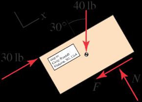
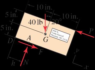
A worker applies the force described below to push a box that weighs 40 lb with center of gravity at point G The surface between the box and ramp has coefficient of friction s D k D 0:25. Determine the normal force and friction force between the box and ramp, and determine if the box will slide up the ramp, down the ramp, or remain at rest.
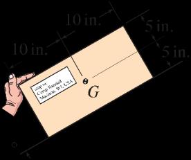
The worker applies a 30 lb force parallel to the ramp.
Solution
Assuming that the block will tend to slide up the ramp, the FBD at the right is drawn, and the equilibrium equations are
With the value of N found above, Coulomb’ s law provides
Thus, the results of Eqs. (1) and (2) do not satisfy Coulomb’ s law, we conclude that the box is not in equilibrium, and
; and the box slides up the ramp with nonzero acceleration. (4)

May 11, 2012 This solutions manual, in any print or electronic form, remains the property of McGraw-Hill, Inc. It may be used and/or possessed only by permission of McGraw-Hill, and must be surrendered upon request of McGraw-Hill. Any duplication or distribution, either in print or electronic form, without the permission of McGraw-Hill, is prohibited. Statics 2e 1333 1333 Solutions Manual
X Fy D 0 W 40 lb/ cos 30ı C N D 0 ) N D 34:64 lb (1) X Fx D 0 W 30 lb .40 lb/ sin 30ı F D 0 ) F D 10 lb: (2)
jF j N D .0:25/.34:64 lb/ D 8:660 lb: (3)
N D 34:6 lb
F D 8:66 lb
;
Problem 9.2
A worker applies the force described below to push a box that weighs 40 lb with center of gravity at point G The surface between the box and ramp has coefficient of friction s D k D 0:25. Determine the normal force and friction force between the box and ramp, and determine if the box will slide up the ramp, down the ramp, or remain at rest.
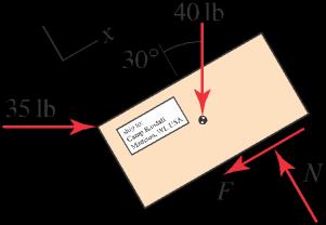
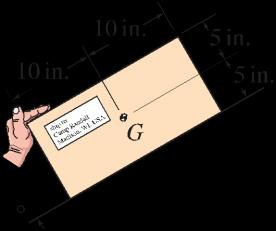
The worker applies a 35 lb force that is horizontal.
Solution
Assuming that the block will tend to slide up the ramp, the FBD at the right is drawn, and the equilibrium equations are
With the value of N found above, Coulomb’ s law provides
Thus, the results of Eqs. (2) and (4) satisfy Coulomb’ s law, we conclude that the box is in equilibrium, and
May 11, 2012 This solutions manual, in any print or electronic form, remains the property of McGraw-Hill, Inc. It may be used and/or possessed only by permission of McGraw-Hill, and must be surrendered upon request of McGraw-Hill. Any duplication or distribution, either in print or electronic form, without the permission of McGraw-Hill, is prohibited. Statics 2e 1334 1334 Solutions Manual
X Fy D 0 W .35 lb/ sin 30ı .40 lb/ cos 30ı C N D 0 (1) ) N D 52:14 lb (2) X Fx D 0 W 35 lb/ cos 30ı 40 lb/ sin 30ı F D 0 (3) ) F D 10:31 lb: (4)
jF j N D 0:25/ 52:14 lb/ D 13:04 lb: (5)
N D 52:1 lb
F D 10:3 lb
the box remains at rest
(6)
;
; and
on the ramp.
Problem 9.3
A person applies a horizontal force P to a rectangular box that is resting on a horizontal surface. The box weighs W D 20 N with center of gravity at point G The surface has coefficients of static and kinetic friction that are equal, with value D 0:4. Assume the box does not tip.
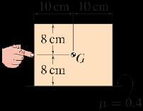
(a) An FBD is shown; this FBD has an error Explain the error and draw the correct FBD.
(b) If P D 7 N, determine the normal force N and friction force F Does the box remain at rest or does it slide? If the box slides, does it do so with constant speed or does it accelerate?
(c) Repeat Part (b) if P D 9 N.
(d) Determine if the assumption that the box does not tip is correct.
Solution
Part (a) In the FBD shown in the problem statement, the normal force N and friction force F are positioned such that moment equilibrium cannot be satisfied unless F D 0; since P > 0 and > 0, the friction force F will be nonzero. To see that moment equilibrium is not satisfied for the FBD shown in the problem statement, consider summing moments about point G to find that P MG ¤ 0. The correct FBD is shown below:
Part (b) With W D 20 N and P D 7 N, we will assume the box is in static equilibrium. Using the FBD shown in Part (a), we obtain
We may now use Coulomb’ s law to check if our assumption of static equilibrium is valid. Coulomb’ s law provides
Since F obtained in Eq. (1) is less than Fmax, our assumption of static equilibrium is valid, and
7 N; N D 20 N; and the box remains at rest. (4)
May 11, 2012 This solutions manual, in any print or electronic form, remains the property of McGraw-Hill, Inc. It may be used and/or possessed only by permission of McGraw-Hill, and must be surrendered upon request of McGraw-Hill. Any duplication or distribution, either in print or electronic form, without the permission of McGraw-Hill, is prohibited. Statics 2e 1335 1335 Solutions Manual
W y P G x F N d
X Fx D 0 W 7 N F D 0 ) F D 7 N; (1) X Fy D 0 W 20 N C N D 0 ) N D 20 N. (2)
Fmax D N D 0:4.20 N/ D 8 N. (3)
F D
Part (c) With N D 20 N and P D 9 N, we will assume the box is in static equilibrium. Using the FBD shown in Part (a), we obtain
We may now use Coulomb’ s law to check if our assumption of static equilibrium is valid. Coulomb’ s law provides
Since F obtained in Eq. (5) is larger than Fmax, our assumption of static equilibrium is incorrect, and we rewrite Eq. (5) as
Hence, the acceleration ax is nonzero. Thus,
F D 8 N; N D 20 N; and the box slides, while accelerating, to the right. (10)
Using the FBD shown in Part (a), X
Part (d) Consider the situation in Part (c) where
Since d < 10 cm, the box does not tip. Note that if the box does not tip for the forces in Part (c), then it also does not tip for the forces in Part (b). Hence,
the assumption that the box does not tip is accurate.
May 11, 2012 This solutions manual, in any print or electronic form, remains the property of McGraw-Hill, Inc. It may be used and/or possessed only by permission of McGraw-Hill, and must be surrendered upon request of McGraw-Hill. Any duplication or distribution, either in print or electronic form, without the permission of McGraw-Hill, is prohibited. Statics 2e 1336 1336 Solutions Manual
X Fx D 0 W 9 N F D 0 ) F D 9 N, (5) X Fy D 0 W 20 N C N D 0 ) N D 20 N. (6)
Fmax D N D 0:4.20 N/ D 8 N: (7)
X Fx D max W 9 N F „ƒ‚… DFmaxD8 N D max; (8)
1 N D max: (9)
F D 8 N
N D
N.
MG D 0 W .8 N/.8 cm/ C .20 N/d D 0 ) d D 3:2 cm (11)
and
20
Problem 9.4
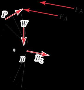
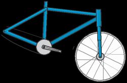
A cross-sectional view through the wheel of a bicycle is shown, where points A, B, and C lie in the same plane. The vertical force applied to the axle is W D 300 N, and the horizontal forces P are applied by the brake to the rim of the wheel (if you are curious, Prob 6.96 on p. 423 shows the brake mechanism that applies forces P ). If the coefficient of friction between the wheel and pavement is 1:1, and the coefficient of friction between the brake material and wheel rim is 0:4, determine the value of P that will cause the wheel to skid on the pavement.

Solution
The FBD for the wheel is shown at the right, where we assume that the wheel rolls in the ´ direction. In this FBD, B´ is the reaction between the axle and the frame of the bicycle. With W D 300 N, we obtain
If the tire skids on the pavement, then
Assuming the brake material slides on the rim of the wheel,
Using Eq. (3), the force P applied by the brake to the rim of the wheel is
May 11, 2012 This solutions manual, in any print or electronic form, remains the property of McGraw-Hill, Inc. It may be used and/or possessed only by permission of McGraw-Hill, and must be surrendered upon request of McGraw-Hill. Any duplication or distribution, either in print or electronic form, without the permission of McGraw-Hill, is prohibited. Statics 2e 1337 1337 Solutions Manual
X Fx D 0 W 300 N C NC D 0 ) NC D 300 N: (1)
FC D C NC D .1:1/ 300 N D 330 N: (2)
FA D AP D .0:4/ P; (3) X MBy D 0 W 2FA .28 cm/ FC .32 cm/ D 0: (4) Thus, FA D 330 N .32 cm/ 2.28 cm/ D 188:6 N: (5)
FA P D 0:4 D 471:4 N: (6)
Problem 9.5
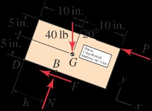
By writing P M D 0 about some convenient point, verify that the distances from the lower left-hand corner of the box (point D) to points A and B in Example 9.1 on p. 540 are 5:18 in: and 11:2 in:, respectively. In view of these results, is motion of the box in fact due to sliding (as assumed in Example 9.1) or is it due to tipping? Explain.
Solution
Figure 2 from Example 9.1, shown again at the right with dimension h added, and Eqs. (1)–(4) from Example 9.1, provide N D 37:59 lb and P D 24:96 lb. These results assume that motion is due to sliding of the box up the incline, and assume that the box does not tip.
Using the FBD shown at the right, we sum moments about point D to write X
MD D 0 W Nh .40 lb/.cos 20ı/.10 in:/ .40 lb/.sin 20ı/.5 in:/ C P
Using N D 37:59 lb and P D 24:96 lb, the above equation is solved to obtain
h D 5:18 in: (2)
Note that for point A to be positioned on the box, the value of h must satisfy 0 h 20 in. Thus, we conclude that point A is positioned on the box and the assumption of no tipping made in Part (a) of Example 9.1 is valid.
Figure 3 from Example 9.1, shown again at the right with dimension h added, and Eq. (5) provide N D 37:59 lb and P D 2:404 lb. These results assume that motion is due to sliding of the box down the incline, and assume that the box does not tip.
Using the FBD shown at the right, the P MD D 0 expression above [Eq. (1)] is still valid, and with N D 37:59 lb and P D 2:404 lb, we obtain
h D 11:2 in: (3)
Thus, we conclude that point B is positioned on the box and the assumption of no tipping made in Part (b) of Example 9.1 is valid.
May 11, 2012 This solutions manual, in any print or electronic form, remains the property of McGraw-Hill, Inc. It may be used and/or possessed only by permission of McGraw-Hill, and must be surrendered upon request of McGraw-Hill. Any duplication or distribution, either in print or electronic form, without the permission of McGraw-Hill, is prohibited. Statics 2e 1338 1338 Solutions Manual
.10 in:/ D 0: (1)
Problem 9.6
The apparatus shown can be used to experimentally determine the angle of static friction, and hence the coefficient of static friction, for many combinations of contacting materials. A block of material C rests on a beam AB Starting with D 0ı , point B is slowly lowered until block C begins to slide. Assuming block C does not tip, show that the value of when sliding starts is equal to the angle of friction , given by Eq. (9.4) on p. 537.

Solution
The FBD shown at the right assumes that impending motion of the block is to the right. The equilibrium equations for the block are:


When is large enough that slip begins, F D N Solving these equations for provides

tan
which is identical to Eq. (9.4).
May 11, 2012 This solutions manual, in any print or electronic form, remains the property of McGraw-Hill, Inc. It may be used and/or possessed only by permission of McGraw-Hill, and must be surrendered upon request of McGraw-Hill. Any duplication or distribution, either in print or electronic form, without the permission of McGraw-Hill, is prohibited. Statics 2e 1339 1339 Solutions Manual
X
y D 0 W W cos C N D 0; ) N D W cos (1) X
x
0 W W sin F D 0; ) F D W sin : (2)
F
F
D
F
1
tan
, (3)
Wsin
D N D W cos D
) D
Problem 9.7
A tool chest has 800 N weight that acts through the midpoint of the chest. The chest is supported by feet at A and rollers at B The surface has a coefficient of friction of 0.3. Determine the value of the horizontal force P necessary to cause motion of the chest to the right, and determine if the motion is sliding or tipping.
Solution
The FBD shown at the right is drawn assuming the tool chest tends to slide to the right.
Tipping analysis: When tipping occurs, By D 0
Motion is impending when P is the smaller of Eqs. (2) and (6). Hence,
and the motion is sliding.
May 11, 2012 This solutions manual, in any print or electronic form, remains the property of McGraw-Hill, Inc. It may be used and/or possessed only by permission of McGraw-Hill, and must be surrendered upon request of McGraw-Hill. Any duplication or distribution, either in print or electronic form, without the permission of McGraw-Hill, is prohibited. Statics 2e 1340 1340 Solutions Manual D
X MA D 0 W P .100 cm/ C .800 N/.50 cm 15 cm/ D 0 (1) ) P D 280:0 N: (2)
analysis:
Ax D Ay X MB D 0 W P .100 cm/ .800 N/.50 cm 15 cm/ C Ay .70 cm/ D 0; (3) X Fx D 0 W P Ax D 0: (4) With Ax D Ay
D 0:3
Eq. (4)
Ay D P =0:3
Eq. (3)
70 cm P . 100 cm C / .800 N/.50 cm 15 cm/ 0; (5) 0:3 ) P D 210:0 N: (6)
Sliding
When sliding occurs,
, where
,
provides
, and with this
becomes
P D 210 N
(7)
Problem 9.8
Determine the value of h in Example 9.2 on p. 541 so that sliding and tipping motion of the traffic barrier are simultaneously impending.
Solution
If motion of the traffic barrier is due to sliding, then Eqs. (1)–(4) of Example 9.2 provide F D 7:00 kN and P D 7:00 kN: (1)
If motion is due to tipping, then the FBD is shown at the right, and X MA D 0 W W.27 cm/ P h D 0; (2)
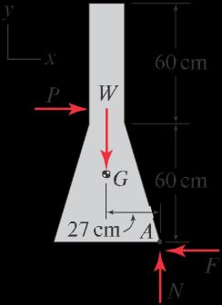
where W was determined in Example 9.2 as W D 15:55 kN.
If the motion is to simultaneously be sliding and tipping, then P D 7:00 kN and we solve Eq. (2) for
May 11, 2012 This solutions manual, in any print or electronic form, remains the property of McGraw-Hill, Inc. It may be used and/or possessed only by permission of McGraw-Hill, and must be surrendered upon request of McGraw-Hill. Any duplication or distribution, either in print or electronic form, without the permission of McGraw-Hill, is prohibited. Statics 2e 1341 1341 Solutions Manual
.15:55 kN/.27 cm/ h D 7:000 kN D 60:0 cm: (3)
Problem 9.9
Carry out the alternate solution described in Example 9.3 on p. 543.
Solution
The FBDs shown in Fig. 4 of Example 9.3 are repeated at the right. These FBDs assume that block B tends to slide to the left and block A tends to slide down. Using these FBDs, we write and solve the following equations.
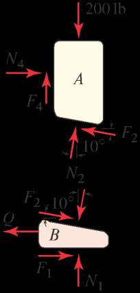
If sliding is impending, then
where D 0:2. While there are seven equations with seven unknowns, these equations are easily solved to obtain and
Since N4 > 0, contact is indeed made at guide E rather than guide D (see Fig. 1 in Example 9.3 for the location of these guides). Since Q > 0, we may infer that block B will not move to the left when Q D 0
May 11, 2012 This solutions manual, in any print or electronic form, remains the property of McGraw-Hill, Inc. It may be used and/or possessed only by permission of McGraw-Hill, and must be surrendered upon request of McGraw-Hill. Any duplication or distribution, either in print or electronic form, without the permission of McGraw-Hill, is prohibited. Statics 2e 1342 1342 Solutions Manual
Block A: X Fx D 0 W N2 sin 10ı F2 cos 10ı C N4 D 0; (1) X Fy D 0 W N2 cos 10ı C F2 sin 10ı C F4 200 lb D 0: (2) Block B: X Fx D 0 W Q C F1 N2 sin 10ı C F2 cos 10ı D 0; (3) B X Fy D 0 W N1 N2 cos 10ı F2 sin 10ı D 0: (4)
F1 D N1; F2 D N2; and F4 D N4; (5)
N1 D 199:1 lb; F1 D 39:82 lb; (6) N2 D 195:3 lb; F2 D 39:05 lb; (7) N4 D 4:553 lb; F4 D 0:911 lb; (8) Q D 44:4 lb: (9)
Problem 9.10
The photograph shows two U.S. Coast Guard icebreakers in an ice field, and a simple model for an ice breaking operation. If the coefficients of static and kinetic friction for contact between the ship’ s bow and ice are 0.08 and 0.06, respectively, and if the ship produces a thrust of 106 lb, determine the normal and friction forces acting on each side of the ship’ s bow as it moves through the ice field with constant velocity. Assume the ship makes contact with the ice only on its bow, and neglect all forces between the ship’ s hull and water except for the thrust.

Solution
The FBD at the right shows only the forces acting in the xy plane. If the ship moves through the ice with constant velocity, the ship is in static equilibrium and thus,

The ship slides against the ice, thus
Solving Eqs. (1) and (2) provides

May 11, 2012 This solutions manual, in any print or electronic form, remains the property of McGraw-Hill, Inc. It may be used and/or possessed only by permission of McGraw-Hill, and must be surrendered upon request of McGraw-Hill. Any duplication or distribution, either in print or electronic form, without the permission of McGraw-Hill, is prohibited. Statics 2e 1343 1343 Solutions Manual
C C
X Fx D 0 W 2N sin 17ı C 2F cos 17ı 106 lb D 0: (1)
F D kN D .0:06/N: (2) 106lb 6 N D 2 sin 17ı .0:06/ cos 17ı/ D 1:43 10 lb and (3) 106lb .0:06/ 4 F D 2. sin 17ı .0:06/ cos 17ı/ D 8:58 10 lb: (4)
Photo credit: United States Coast Guard.
Problem 9.11
The structure consists of two uniform members AB and BC , each weighing 2 kN. The members are pinned to each other at B, and the structure is supported by a pin at C and a surface at A having coefficient of static friction 1.2. Determine the largest positive value P the structure can support.
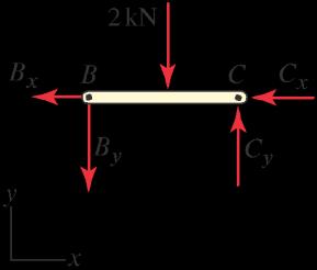
Solution
The FBDs shown at the right are drawn assuming that point A tends to slide to the left. Using these FBDs, we write and solve the following equations.
If motion is impending, then F D N D .1:2/N . Solving these equations for N and F provides


May 11, 2012 This solutions manual, in any print or electronic form, remains the property of McGraw-Hill, Inc. It may be used and/or possessed only by permission of McGraw-Hill, and must be surrendered upon request of McGraw-Hill. Any duplication or distribution, either in print or electronic form, without the permission of McGraw-Hill, is prohibited. Statics 2e 1344 1344 Solutions Manual
X MB D 0 W N.4 m/ C F .3 m/ C .2 kN/.2 m/ D 0:
Member AB:
(1)
N D 10:00 kN and F D 12:00 kN: (2) Member BC: X MC D 0 W .2 kN/.2:5 m/ C By .5 m/ D 0 ) By D 1:000 kN (3) Member AB: X Fy D 0 W N 2 kN P C By D 0 ) P D 7:00 kN. (4)
Problem 9.12
Water ( D 62:4 lb=ft3) is retained by a uniform thin semicircular dam having 1 ft radius and 3 ft depth into the plane of the figure. The dam weighs 60 lb and is supported by a cable AC and by frictional contact with the bottom of the channel at B Determine the minimum coefficient of friction so that the dam does not slip at B.
Solution
The FBD shown at the right is drawn assuming that point B tends to slide to the left. The fluid pressure at B is
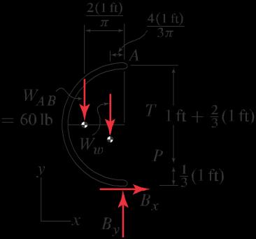
The resultant force due to the fluid pressure loading is

The weight of the gate is WAB D 60 lb and the weight of the volume of water included in the FBD is
The equilibrium equations are
May 11, 2012 This solutions manual, in any print or electronic form, remains the property of McGraw-Hill, Inc. It may be used and/or possessed only by permission of McGraw-Hill, and must be surrendered upon request of McGraw-Hill. Any duplication or distribution, either in print or electronic form, without the permission of McGraw-Hill, is prohibited. Statics 2e 1345 1345 Solutions Manual 2 4 3 5 5
pB D .1 ft
ft2: (1)
/ D 62:40 lb=
P D 1 .62:4 lb=ft2/.1 ft/.3 ft/ D 93:60 lb: (2)
Ww D 1 .1 ft/2.3 ft/ D 147:0 lb: (3) X MA D 0 W WAB 2.1 ft/ C Ww 4.1 ft/ 3 C Bx.2 ft/ P .2 ft 1ft / D 0 ) Bx D 27:70 lb; (4) X Fx D 0 W T 3 P C Bx D 0 ) T D 109:8 lb; (5) X Fy D 0 W T 4 WAB Ww C By D 0 ) By D 294:9 lb: (6) If
F D N ) Bx D By
0:0939 is needed to
B. (7)
motion is impending then
. Therefore
prevent slip at point
Problem 9.13
A long concrete retaining wall with 2:4 103 kg=m3 density is used to support a soil embankment. Assuming the soil behaves as a fluid with 1:5 103 kg=m3 density, determine the required coefficient of friction so the wall does not slip along its base, and determine if the wall is safe from tipping.
Solution
The FBD is shown at the right. The weight W of the concrete, assuming a 1 m thickness in the direction perpendicular to the plane of the figure, is
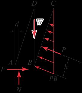
84,760 N = 84.76 kN.
the distance h from point B to the line of action of P is
To prevent slip at the base of the retaining wall, the minimum coefficient of friction is
66:22 kN
May 11, 2012 This solutions manual, in any print or electronic form, remains the property of McGraw-Hill, Inc. It may be used and/or possessed only by permission of McGraw-Hill, and must be surrendered upon request of McGraw-Hill. Any duplication or distribution, either in print or electronic form, without the permission of McGraw-Hill, is prohibited. Statics 2e 1346 1346 Solutions Manual 2 x D
W D cgVC (1) h1 i 2:4 103 kg m3 m 9:81 s2 2 .1:2 m/.3 m/.1 m/ 2 (2) D
(3) The
pB D sg .3 m/ D N 1:5 103 kN kg m3 m 9:81 s2 .3 m/ (4) D 44,150 m2 D 44:15 m2 : (5) The force
the soil to the
wall is 1 q 2 2 P D 2 pB .1:2 m/ C .3 m/ .1 m/ D 71:32 kN, (6)
1q h D 3 Sliding
.1:2 m/2 C .3 m/ 1:2 D 1:077 m: (7) X Fy D 0 W N W C P p D 0 ) N D 58:27 kN; (8) 10:44 X F D 0 W F P p 3 D 0 ) F D 66:22 kN: (9) 10:44
soil pressure at point B is
applied by
retaining
and
analysis: Using the FBD,
F
May 11, 2012 This solutions manual, in any print or electronic form, remains the property of McGraw-Hill, Inc. It may be used and/or possessed only by permission of McGraw-Hill, and must be surrendered upon request of McGraw-Hill. Any duplication or distribution, either in print or electronic form, without the permission of McGraw-Hill, is prohibited. Statics 2e 1347 1347 Solutions Manual Tipping analysis: Using the FBD, D N D 58:27 kN D 1.136. (10) X MB D 0 W N (1.2 m d/ C P h D 0; (11)
Using the values of P; h, and N obtained earlier, Eq. (12) provides
Since d is negative, the retaining wall is not safe from tipping.
May 11, 2012 This solutions manual, in any print or electronic form, remains the property of McGraw-Hill, Inc. It may be used and/or possessed only by permission of McGraw-Hill, and must be surrendered upon request of McGraw-Hill. Any duplication or distribution, either in print or electronic form, without the permission of McGraw-Hill, is prohibited. Statics 2e 1348 1348 Solutions Manual d D 1:2 m P h : (12) N
d D 0:118 m
(13)
:
Problem 9.14
A long concrete gravity dam retains water in a reservoir The surface between the dam and earth has coefficients of friction s D 0:8 and k D 0:7. When the reservoir is completely full (i.e., h D 8 m), determine if the dam is safe from both overturning (tipping) and sliding along its base. The specific weight of concrete is c D 25 kN=m3 and the density of water is w D 103 kg=m3
The FBD for the dam and a volume of water is shown at the right. The water pressure at the bottom of the reservoir (i.e., base of the dam) is
For a 1 m thick section of dam (into the plane of the figure), the resultant force P due to the fluid pressure loading is

The weight of the water and the weight of the concrete in the FBD are, respectively
Sliding analysis: Using the FBD shown above, the equilibrium equations are
For impending slip, F D sN , and combining this with Eqs. (5) and (6), we obtain the minimum coefficient of static friction to prevent sliding
Since the value of s given in the problem statement exceeds s/min (i.e., since 0:8 > 0:3758), the dam will not slide.
Tipping analysis: Using the FBD shown above,
Since 0 < ` 6 m, the dam will not tip.
May 11, 2012 This solutions manual, in any print or electronic form, remains the property of McGraw-Hill, Inc. It may be used and/or possessed only by permission of McGraw-Hill, and must be surrendered upon request of McGraw-Hill. Any duplication or distribution, either in print or electronic form, without the permission of McGraw-Hill, is prohibited. Statics 2e 1349 1349 Solutions Manual D w D 3 D 4 D 2 w D w water D 3 2 s2
Solution
kg p g.8 m/ 10 .9:81 m3 m N /.8 m/ 7:848 10 78:48 s2 m2 kN : (1) m2
P D 1 p.8 m/.1 m/ D 313:9 kN: (2)
kg W gV .10 /.9:81 m3 m / 1 .6 m/.8 m/.1 m/ D 2:354 105 N D 235:4 kN; (3) kN 1 Wc D cVconcrete D .25 m3 / 2 .6 m/.8 m/.1 m/ D 600 kN: (4)
X Fy D 0 W N Wc Ww D 0 ) N D 835:4 kN; (5) X Fx D 0 W F P D 0 ) F D 313:9 kN: (6)
F 313:9 kN s/min D N D 835:4 kN D 0:3758: (7)
MA D 0 W N` Wc 1 .6 m/ Ww 2 .6 m/ C P 1 .8 m/ D 0 (8) 3 3 3 .835:4 kN/` .600 kN/ 1 .6 m/ .235:4 kN/ 2 .6 m/ C .313:9 kN/ 1 .8 m/ D 0; (9) 3 3 3 ) ` D 1:56 m: (10)
X
The dam will not slide or tip when the reservoir is completely full. (11)
May 11, 2012 This solutions manual, in any print or electronic form, remains the property of McGraw-Hill, Inc. It may be used and/or possessed only by permission of McGraw-Hill, and must be surrendered upon request of McGraw-Hill. Any duplication or distribution, either in print or electronic form, without the permission of McGraw-Hill, is prohibited. Statics 2e 1350 1350 Solutions Manual
Problem 9.15
Repeat Prob 9.14 if the reservoir is on the left-hand side of the dam.
Solution
The FBD for the dam is shown at the right. The water pressure at the bottom of the reservoir (i.e., point A) is
For a 1 m thick section of dam (into the plane of the figure), the resultant force P due to the fluid pressure loading is
The weight of the concrete in the FBD is
Sliding analysis: Using the FBD shown above, the equilibrium equations are
For impending slip, F D sN , and combining this with Eqs. (4) and (5), we obtain the minimum coefficient of static friction to prevent sliding
Since the value of s given in the problem statement exceeds s/min (i.e., since 0:8 > 0:5232), the dam will not slide.
Tipping analysis: Using the FBD shown above,
Since 0 < ` 6 m, the dam will not tip.
The dam will not slide or tip when the reservoir is completely full. (10)
May 11, 2012 This solutions manual, in any print or electronic form, remains the property of McGraw-Hill, Inc. It may be used and/or possessed only by permission of McGraw-Hill, and must be surrendered upon request of McGraw-Hill. Any duplication or distribution, either in print or electronic form, without the permission of McGraw-Hill, is prohibited. Statics 2e 1351 1351 Solutions Manual X Fy D 0 W N Wc D 0 ) N D 600 kN; X Fx D 0 W P F D 0 ) F D 313:9 kN: D w D 3 D 4 D 2
kg p g.8 m/ 10 .9:81 m3 m N /.8 m/ 7:848 10 78:48 s2 m2 kN : (1) m2
P D 1 p.8 m/.1 m/ D 313:9 kN: (2)
kN 1 Wc D cVconcrete D .25 m3 / 2 .6 m/.8 m/.1 m/ D 600 kN: (3)
(4) (5)
F s/min D N D 313:9 kN 600 kN D 0:5232: (6)
X MA D 0 W N` Wc 1 .6 m/ P 1 .8 m/ D 0 (7) 3 3 .600 kN/` .600 kN/ 1 .6 m/ .313:9 kN/ 1 .8 m/ D 0; (8) 3 3
) ` D 3:40 m: (9)
Problem 9.16
The owner of a small concrete gravity dam is considering attaching steel plate to the face of the dam so that a greater depth of water can be retained. The surface between the dam and earth has coefficients of friction s D 0:6 and k D 0:55. Determine if the dam is safe from both overturning (tipping) and sliding along its base. The specific weights of concrete and water are c D 150 lb=ft3 and w D 62:4 lb=ft3 , respectively. Neglect the weight of the steel plate.
Solution
The FBD for the dam is shown at the right. The water pressure at the bottom of the reservoir is
For a 1 ft thick section of dam (into the plane of the figure), the resultant force P due to the fluid pressure loading is

The weight of the concrete dam is W1 C W2 where W1 and W2 are
Sliding analysis: Using the FBD shown above, the equilibrium equations are
For impending slip, F D sN , and combining this with Eqs. (4) and (5), we obtain the minimum coefficient of static friction to prevent sliding
Since s/min exceeds the value of s given in the problem statement (i.e., since 0:624 > 0:6), the dam will fail by sliding.
Note that the dam may also fail by tipping, thus we carry out the following analysis.
Tipping analysis: Using the FBD shown above,
Since 0 ` 2 ft, the dam will not tip.
May 11, 2012 This solutions manual, in any print or electronic form, remains the property of McGraw-Hill, Inc. It may be used and/or possessed only by permission of McGraw-Hill, and must be surrendered upon request of McGraw-Hill. Any duplication or distribution, either in print or electronic form, without the permission of McGraw-Hill, is prohibited. Statics 2e 1352 1352 Solutions Manual 2 2 3 3
lb lb p D w .3 ft/ D 62:4 ft3 .3 ft/ D 187:2 ft2 : (1)
P D 1 p.3 ft/.1 ft/ D 280:8 lb: (2)
W1 D c.1 ft/.2 ft/.1 ft/ D 300 lb; and W2 D c 1 .1 ft/.2 ft/.1 ft/ D 150 lb: (3)
X Fy D 0 W N W1 W2 D 0 ) N D 450 lb; (4) X Fx D 0 W P F D 0 ) F D 280:8 lb: (5)
F s/min D N D 280:8 lb 450 lb D 0:624: (6)
X MA D 0 W P .1 ft/ C W1.1:5 ft/ C W2 2 .1 ft/ N` D 0 (7) .280:8 lb/.1 ft/ C .300 lb/.1:5 ft/ C .150 lb/ 2 .1 ft/ .450 lb/` D 0; (8) ) ` D 0:598 ft: (9)
Problem 9.17
A wedge is used to level a structure. All contact surfaces have coefficients of static and kinetic friction of 0.3 and 0.25, respectively, and W D 500 N. Assume the dimensions of the wedge are small. Determine the value of P to cause impending motion of the wedge:
(a) To the left.
(b) To the right.
Solution
Part (a) Wedge C slides to the left, which allows the the FBDs shown at the right to be drawn.
motion is impending, then
Using Eqs. (2) and (3), Eq. (4) is solved to obtain
and Eq. (5) is solved to obtain
May 11, 2012 This solutions manual, in any print or electronic form, remains the property of McGraw-Hill, Inc. It may be used and/or possessed only by permission of McGraw-Hill, and must be surrendered upon request of McGraw-Hill. Any duplication or distribution, either in print or electronic form, without the permission of McGraw-Hill, is prohibited. Statics 2e 1353 1353 Solutions Manual
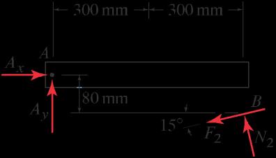
Beam AB: X MA D 0 W .500 N/.300 mm/ C N2 cos 15ı.600 mm/ N2 sin 15ı.80 mm/ F2 cos 15ı.80 mm/ F2 sin 15ı.600 mm/ D 0: (1)
F1 D sN1 D .0:30/N1 and F2 D sN2 D .0:3/N2: (2)
Eqs. (1)
N2
F2
N2 D 306:7 N; F2 D 92:01 N: (3) Wedge C: X Fy D 0 W N1 N2 cos 15ı C F2 sin 15ı D 0; (4) X Fx D 0 W F1 C N2 sin 15ı C F2 cos 15ı P D 0: (5)
If
Solving
and (2) for
and
provides
N1 D 272:4 N; F1 D 81:73 N: (6)
P D 250 N: (7)
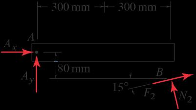
Part (b) Wedge C slides to the right, which allows the the FBDs shown at the right to be drawn. Note that these FBDs are identical to those in Part (a), except that the directions of the friction forces F1,
2, and F3 are opposite.
If motion is impending, then
Using
The negative result for P means that the force needed to move wedge C to the right must be applied to the right.
May 11, 2012 This solutions manual, in any print or electronic form, remains the property of McGraw-Hill, Inc. It may be used and/or possessed only by permission of McGraw-Hill, and must be surrendered upon request of McGraw-Hill. Any duplication or distribution, either in print or electronic form, without the permission of McGraw-Hill, is prohibited. Statics 2e 1354 1354 Solutions Manual
F
AB: X MA D 0 W .500 N/.300 mm/ C N2 cos 15ı.600 mm/ N2 sin 15ı.80 mm/ C F2 cos 15ı.80 mm/ C F2 sin 15ı.600 mm/ D 0: (8)
Beam
F1 D sN1 D .0:30/N1 and F2 D sN2 D .0:3/N2: (9)
Eqs. (8) and (9) for N2 and F2 provides N2 D 238:6 N; F2 D 71:59 N: (10) Wedge C: X Fy D 0 W N1 N2 cos 15ı F2 sin 15ı D 0; (11) X Fx D 0 W F1 C N2 sin 15ı F2 cos 15ı P D 0: (12)
Solving
Eqs.
Eq.
N1 D 249:0 N; F1 D 74:70 N: (13) and Eq. (12)
P D 82:1 N: (14)
(9) and (10),
(11) is solved to obtain
is solved to obtain
Problem 9.18
Blocks A and B each have 2 kg mass. All contact surfaces have the same coefficient of friction. Determine the force P needed to cause impending motion of block B to the left if the coefficient of static friction is 0.4. Solution
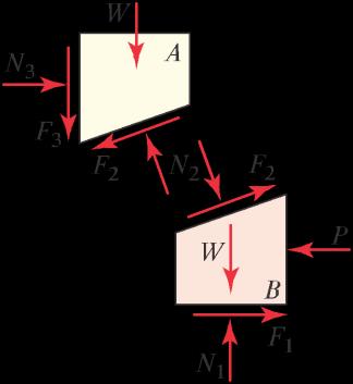
Each block has weight W D .2 kg/.9:81 m=s2/ D 19:62 N. With block B sliding to the left and block A sliding upward, the FBDs are shown at the right.
If motion is impending, then
While there are seven equations with seven unknowns, these are easily solved, as follows. Using Eq. (5), Eqs. (1) and (2) become, respectively,
Multiplying Eq. (7) by 0.4 and adding this to Eq. (6) provides one equation where N2 is the only unknown, and solving for this provides N2 D 38:04 N. Substituting N2 into the other equations then provides the remaining unknowns, with the results
May 11, 2012 This solutions manual, in any print or electronic form, remains the property of McGraw-Hill, Inc. It may be used and/or possessed only by permission of McGraw-Hill, and must be surrendered upon request of McGraw-Hill. Any duplication or distribution, either in print or electronic form, without the permission of McGraw-Hill, is prohibited. Statics 2e 1355 1355 Solutions Manual
Block A: X Fy D 0 W N2 cos 20ı F2 sin 20ı F3 W D 0; (1) X Fx D 0 W N2 sin 20ı F2 cos 20ı C N3 D 0: (2) Block B: X Fy D 0 W N1 N2 cos 20ı C F2 sin 20ı W D 0; (3) X Fx D 0 W F1 C N2 sin 20ı C F2 cos 20ı P D 0: (4)
F1 D sN1 D .0:4/N1; F2 D sN2 D .0:4/N2; and F3 D sN3 D .0:4/N3: (5)
N2 cos 20ı .0:4/N2 sin 20ı .0:4/N3 W D 0; (6) N2 sin 20ı .0:4/N2 cos 20ı C N3 D 0: (7)
N1 D 50:16 N; F1 D 20:07 N; (8) N2 D 38:04 N; F2 D 15:22 N; (9) N3 D 27:31 N; F3 D 10:92 N; (10) P D 47:4 N: (11)
Problem 9.19
Blocks A and B each have 2 kg mass. All contact surfaces have the same coefficient of friction. Determine the force P needed to cause impending motion of block B to the left if the coefficient of static friction is 0.3. Solution
Each block has weight W D .2 kg/.9:81 m=s2/ D 19:62 N. With block B sliding to the left and block A sliding upward, the FBDs are shown at the right.
If motion is impending, then
While there are seven equations with seven unknowns, these are easily solved, as follows. Using Eq. (5), Eqs. (1) and (2) become, respectively,
Multiplying Eq. (7) by 0.3 and adding this to Eq. (6) provides one equation where N2 is the only unknown, and solving for this provides N2 D 30:19 N. Substituting N2 into the other equations then provides the remaining unknowns, with the results
May 11, 2012 This solutions manual, in any print or electronic form, remains the property of McGraw-Hill, Inc. It may be used and/or possessed only by permission of McGraw-Hill, and must be surrendered upon request of McGraw-Hill. Any duplication or distribution, either in print or electronic form, without the permission of McGraw-Hill, is prohibited. Statics 2e 1356 1356 Solutions Manual
Block A: X Fy D 0 W N2 cos 20ı F2 sin 20ı F3 W D 0; (1) X Fx D 0 W N2 sin 20ı F2 cos 20ı C N3 D 0: (2) Block B: X Fy D 0 W N1 N2 cos 20ı C F2 sin 20ı W D 0; (3) X Fx D 0 W F1 C N2 sin 20ı C F2 cos 20ı P D 0: (4)
F1 D sN1 D .0:3/N1; F2 D sN2 D .0:3/N2; and F3 D sN3 D .0:3/N3: (5)
N2 cos 20ı .0:3/N2 sin 20ı .0:3/N3 W D 0; (6) N2 sin 20ı .0:3/N2 cos 20ı C N3 D 0: (7)
N1 D 44:89 N; F1 D 13:47 N; (8) N2 D 30:19 N; F2 D 9:057 N; (9) N3 D 18:84 N; F3 D 5:651 N; (10) P D 32:3 N: (11)
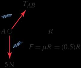
Problem 9.20
A roll of paper weighs 5 N with center of gravity at point A The roll is supported by a steel bar AB that has negligible weight, and the roll rests against a vertical wall with equal coefficients of static and kinetic friction of 0.5. If the paper tears when angle reaches 20ı , determine the strength of the sheet of paper


The FBD is shown at the right, and the equilibrium equations are
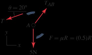
Using Eq. (2), Eqs. (3) and (4) become
Equations (5) and (6) may be solved a variety of ways to obtain T , and we use the following approach. Multiply Eq. (5) by 80, and multiply Eq. (6) by 60, and add the results, thus canceling TAB , to obtain the strength of the paper as

May 11, 2012 This solutions manual, in any print or electronic form, remains the property of McGraw-Hill, Inc. It may be used and/or possessed only by permission of McGraw-Hill, and must be surrendered upon request of McGraw-Hill. Any duplication or distribution, either in print or electronic form, without the permission of McGraw-Hill, is prohibited. Statics 2e 1357 1357 Solutions Manual T T D
Solution
X MA D 0 W T .60 mm/ .0:5/ R .60 mm/ D 0; (1) ) R D 2T; (2) X Fx D 0 W T cos 20ı C TAB X Fy D 0 W T sin 20ı C TAB 60 100 80 100 R D 0; (3) .0:5/ R 5 N D 0: (4)
60 T cos 20ı C TAB 100 2T D 0; (5) 80 T sin 20ı C TAB 100 .0:5/ 2T 5 N D 0: (6)
h i 80.cos 20ı C 2/ C 60.sin 20ı C 1/ C 60.5 N/ D 0; (7) 60.5N/ 80 cos 20ı C 2/ C 60 sin 20ı C 1/ D 1.940 N. (8)
Problem 9.21
In Prob 9.20, let the strength of the paper be 4 N. Determine the largest value of angle so that paper may be pulled off the roll without tearing. Hint: The equilibrium equations are difficult to solve analytically Thus, a solution using software such as Mathematica or Maple is helpful, or an approximate solution (i.e., graphical or by trial and error) to obtain with two-digit accuracy is also acceptable.
Solution
The FBD is shown at the right, and the equilibrium equations are


Equations (2)–(4) could be solved simultaneously using software such as Mathematica or Maple to obtain TAB and , but we elect to first simplify these equations slightly. Using Eq. (2), Eqs. (3) and (4) become

We combine Eqs. (5) and (6) to eliminate TAB as follows. Multiply Eq. (5) by 80, multiply Eq. (6) by 60, and add the results to obtain
is simplified to obtain
We use Mathematica to solve Eq. (8) as follows.
May 11, 2012 This solutions manual, in any print or electronic form, remains the property of McGraw-Hill, Inc. It may be used and/or possessed only by permission of McGraw-Hill, and must be surrendered upon request of McGraw-Hill. Any duplication or distribution, either in print or electronic form, without the permission of McGraw-Hill, is prohibited. Statics 2e 1358 1358 Solutions Manual
X MA D0 W .4 N/.60 mm/ .0:5/ R .60 mm/ D 0; (1) ) R D 8 N; (2) 60 X Fx D0 W 4 N cos C TAB X Fy D0 W 4 N sin C TAB 100 80 100 R D 0; (3) .0:5/ R 5 N D 0: (4)
60 4 N cos C TAB 100 8 N D 0; (5) 80 4 N sin C TAB 100 9 N D 0: (6)
.80/. 4 N/ cos .80/.8 N/ C .60/.4 N/ sin C
N
(7)
16 cos 12 sin
.60/.9
/ D 0;
which
C 5 D 0: (8)
The negative solution for is discarded because it is physically impossible, and hence the angle at which the paper will tear is
May 11, 2012 This solutions manual, in any print or electronic form, remains the property of McGraw-Hill, Inc. It may be used and/or possessed only by permission of McGraw-Hill, and must be surrendered upon request of McGraw-Hill. Any duplication or distribution, either in print or electronic form, without the permission of McGraw-Hill, is prohibited. Statics 2e 1359 1359 Solutions Manual
180ı D 1:17998 radian radian D 67:61ı . (9)
Rather than using software to obtain the solution, an approximate solution with acceptable accuracy can be obtained using trial and error. In the following table, we guess for a value of , and then evaluate the left-hand side of Eq. (8), with the following results
Clearly, the solution for is between 67ı and 68ı , and with a little more experimentation, the solution is found to be closer to 68ı . Thus, to two digit accuracy, the angle at which the paper will tear is
Alternate solution An analytic solution may be found as follows. Squaring each of Eqs. (5) and (6) and adding the results provides
Using the quadratic formula, the two solutions to Eq. (12) are
Determining the values of that correspond to these solutions is somewhat subtle. To this end, Eqs. (5) and (6) may be rearranged to obtain, respectively,
solution in Eq. (13), Eqs. (14) and (15) provide for
Since these values of are different, we conclude that TAB D 8:127 N is not a solution to this problem. For the second solution in Eq. (13), Eqs. (14) and (15) provide
May 11, 2012 This solutions manual, in any print or electronic form, remains the property of McGraw-Hill, Inc. It may be used and/or possessed only by permission of McGraw-Hill, and must be surrendered upon request of McGraw-Hill. Any duplication or distribution, either in print or electronic form, without the permission of McGraw-Hill, is prohibited. Statics 2e 1360 1360 Solutions Manual AB 4 N TAB
16cos 12sin C5 65ı 0:8862 66ı 0:5452 67ı 0:2056 68ı 0:1325 69ı 0:4691 70ı 0:8040
Š 68ı: (10)
.16 N2/.sin2 C cos2 / D T 2 .24 N/TAB C 145 N2 D 0: (11)
T 2 2 AB .24 N/TAB C 129 N
Noting that sin2 C cos2 D 1, Eq. (11) becomes
D 0: (12) TAB D 8:127 N and TAB D 15:87 N: (13)
D cos 1 1h 60 100 i 8 N ; (14) D sin 1 1h T 80 9 N i (15) 4 N AB 100 :
TAB
N
Eq. (14) ) D 141:3ı; and (16) Eq. (15) ) D 38:65ı: (17)
For the first
D 8:127
;
TAB D
N; Eq. (14) ) D 67:61ı;
(18) Eq. (15) ) D 67:61ı: (19)
for
15:87
and
Since these values of agree, we conclude that the paper will tear when
May 11, 2012 This solutions manual, in any print or electronic form, remains the property of McGraw-Hill, Inc. It may be used and/or possessed only by permission of McGraw-Hill, and must be surrendered upon request of McGraw-Hill. Any duplication or distribution, either in print or electronic form, without the permission of McGraw-Hill, is prohibited. Statics 2e 1361 1361 Solutions Manual
D 67:61ı: (20)
Problem 9.22
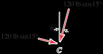
The bicycle shown has a brake for each wheel. The rider and bicycle weigh 120 lb with center of gravity at point C , and the bicycle descends a straight slope with D 15ı For each of the braking situations given below, determine the minimum coefficient of kinetic friction between the tires and pavement so that the bicycle will descend the slope at a uniform speed, and determine if the bicycle is safe from tipping.
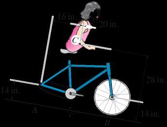
(a) Only the rear brake is applied, causing the rear wheel to skid on the pavement.
(b) Only the front brake is applied, causing the front wheel to skid on the pavement.
(c) Both the rear and front brakes are applied, causing both wheels to skid on the pavement.
Solution
The FBD for the bicycle is shown at the right, where either or both of the wheels may have their brakes applied.
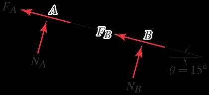
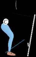
Part (a) If only the rear brake is applied, causing the rear wheel to skid on the pavement, then

Equations (1)–(4) are easily solved to obtain


Since NA is positive, the bicycle is safe from tipping.
Part (b) If only the front brake is applied, causing the front wheel to skid on the pavement, then
Equations (1)–(3) and Eq. (7) are easily solved to obtain

May 11, 2012 This solutions manual, in any print or electronic form, remains the property of McGraw-Hill, Inc. It may be used and/or possessed only by permission of McGraw-Hill, and must be surrendered upon request of McGraw-Hill. Any duplication or distribution, either in print or electronic form, without the permission of McGraw-Hill, is prohibited. Statics 2e 1362 1362 Solutions Manual
X MA D 0 W NB .36 in./ .120 lb/ cos 15ı .16 in./ .120 lb/ sin 15ı .42 in./ D 0; (1) X Fx D 0 W FA FB C .120 lb/ sin 15ı D 0; (2) X Fy D 0 W NA C NB .120 lb/ cos 15ı D 0: (3)
FA D NA and FB D 0: (4)
D 1:103; (5) NA D 28:16 lb, and NB D 87:75 lb (6)
FA D 0 and FB D NB : (7)
D 0:3540; (8)
May 11, 2012 This solutions manual, in any print or electronic form, remains the property of McGraw-Hill, Inc. It may be used and/or possessed only by permission of McGraw-Hill, and must be surrendered upon request of McGraw-Hill. Any duplication or distribution, either in print or electronic form, without the permission of McGraw-Hill, is prohibited. Statics 2e 1363 1363 Solutions Manual NA D 28:16 lb, and NB D 87:75 lb: (9) Since NA is positive, the bicycle is safe from tipping.
Part (c) If both brakes are applied, causing both wheels to skid on the pavement, then
FA D NA and FB D NB : (10)
Equations (1)–(3) and Eq. (10) are easily solved to obtain
D 0:2680; (11)
NA D 28:16 lb, and NB D 87:75 lb. (12)
Since NA is positive, the bicycle is safe from tipping.
Remark It is perhaps unexpected that the normal forces at each wheel, NA and NB , are the same for all three braking situations. That this is true can be seen from Eq. (1), which yields NB, and Eq. (3), which then yields NA.
May 11, 2012 This solutions manual, in any print or electronic form, remains the property of McGraw-Hill, Inc. It may be used and/or possessed only by permission of McGraw-Hill, and must be surrendered upon request of McGraw-Hill. Any duplication or distribution, either in print or electronic form, without the permission of McGraw-Hill, is prohibited. Statics 2e 1364 1364 Solutions Manual
Problem 9.23
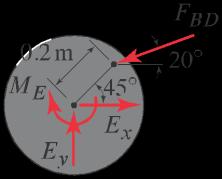
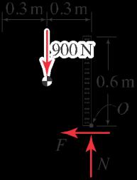
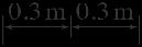
The machine shown is used to move boxes. Bar ABC slides horizontally in the bearing of the fixed machine housing. Points B, C , and D are pins, and point C has a frictionless roller The flywheel E rotates clockwise under the action of moment ME . The horizontal surface on which the box rests has coefficients of friction s D 0:3 and k D 0:25, and all other contact surfaces are frictionless. If the box weighs 900 N, determine the moment ME that must be applied to the flywheel to initiate motion of the box, and determine if the motion is sliding or tipping.
Solution
Sliding analysis: The FBDs for the various members of the machine are shown at the right.
Box: X
Fy D 0 W N 900 N D 0 ) N D 900 N; (1) X
Fx D 0 W Cx F D 0 ) Cx D F: (2)
If sliding of the box is impending, then
F D sN D .0:3/.900 N/ D 270 N; (3)

and from Eq. (2), Cx D 270 N: (4)
Tipping analysis: For tipping, the FBD of the box is shown at the right, and Box: X MO D 0 W .900 N/.0:3 m/ Cx.0:5 m/ D 0; (5) ) Cx D 540 N: (6)
Motion of the box will occur when Cx reaches the smaller of Eqs. (4) and (6). Thus, Cx D 270 N, the box will slide rather than tip, and using this value of Cx, we carry out the remainder of the solution.
Member ABC: X F
(7)
(8)
An expanded view of the FBD for the flywheel is shown at the right, and using this, Flywheel E: X ME D 0 W FBD.cos 20
With FBD D 287:3 N, solving the above for ME provides
E D 24:3 N m; and the box will slide rather than tip: (10)

May 11, 2012 This solutions manual, in any print or electronic form, remains the property of McGraw-Hill, Inc. It may be used and/or possessed only by permission of McGraw-Hill, and must be surrendered upon request of McGraw-Hill. Any duplication or distribution, either in print or electronic form, without the permission of McGraw-Hill, is prohibited.
2e 1365 1365
Statics
Solutions Manual
x D 0 W FBD cos 20ı Cx D 0;
270 N ) FBD D cos 20ı D 287:3 N:
ı
ME
ı/.0:2 m/.sin 45ı/ FBD sin 20ı/.0:2 m/.cos 45
/
D 0: (9)
M
Problem 9.24
An 8 ft long ladder has seven rungs. The rungs are spaced 1 ft apart, and the top and bottom rungs are 1 ft from their respective ends of the ladder. The top of the ladder has a roller Neglect the weight of the ladder and assume the worker’ s hand applies no force to the ladder.
(a) If the worker weighs 140 lb and stands on the middle rung, determine the minimum value of the coefficient of friction so that the ladder does not slide.
(b) If the worker weighs 140 lb and stands on a different rung, does your answer to Part (a) change? Explain.
(c) If the worker weighs more than 140 lb and stands on the middle rung, does your answer to Part (a) change? Explain.
Part (a) Using the FBD shown at the right, the equilibrium equations are
If motion is impending, F D sN . Therefore, the minimum coefficient of static friction to prevent slip is

Part (b) If the worker moves to a different rung, the answer to Part (a) will change, as follows. Regardless of the worker’ s position, N does not change. If the worker moves to a higher rung, from Eq. (1), Bx will increase, hence from Eq. (4), F will increase. Thus, from Eq. (5), the value of to prevent slip will also increase. If the worker moves to a lower rung, Bx and F will decrease, hence the value of to prevent slip will also decrease.
Part (c) If the worker’ s weight increases, both F and N in Part (a) increase in proportion. However, the ratio F=N remains the same, so the value min D 0:289 does not change.
May 11, 2012 This solutions manual, in any print or electronic form, remains the property of McGraw-Hill, Inc. It may be used and/or possessed only by permission of McGraw-Hill, and must be surrendered upon request of McGraw-Hill. Any duplication or distribution, either in print or electronic form, without the permission of McGraw-Hill, is prohibited. Statics 2e 1366 1366 Solutions Manual
Solution
X MA D 0 W W.4 ft/ cos 60ı C Bx.8 ft/ sin 60ı D 0; (1) ) Bx D 40:41 lb; (2) X Fy D 0 W N W D 0 ) N D 140 lb: (3) X Fx D 0 W F Bx D 0 ) F D 40:41 lb: (4)
F min D N D 40:41 lb 140 lb D 0:289: (5)
Problem 9.25
In Prob 9.24, the roller at B is removed and the surfaces at A and B both have the same coefficient of friction. If the worker weighs 140 lb and stands on the middle rung, determine the minimum value of the coefficient of friction so that the ladder does not slide. Hint: The use of mathematical software is helpful, but is not required. Solution
The equilibrium equations are:
where is the coefficient of static friction. Equations (1)–(5) are five equations in five unknowns (N1, F1, N2, F2, and ). Using computer software, the solution for the coefficient of friction for impending slip, and hence the minimum value of to prevent slip, is easily obtained as
Alternate solution Rather than use computer software to solve Eqs. (1)–(5), they can be solved by hand, as follows. Combine Eqs. (1) and (5), and divide by 4 ft to obtain
Equation (7) is easily solved to obtain N2, and with Eq. (5), F2 is also obtained, with the results
Equation (3) provides
2, and Eq. (4) provides
1 Since N2 is known, we obtain
May 11, 2012 This solutions manual, in any print or electronic form, remains the property of McGraw-Hill, Inc. It may be used and/or possessed only by permission of McGraw-Hill, and must be surrendered upon request of McGraw-Hill. Any duplication or distribution, either in print or electronic form, without the permission of McGraw-Hill, is prohibited. Statics 2e 1367 1367 Solutions Manual D
X MA D 0 W W.4 ft/ cos 60ı C N2.8 ft/ sin 60ı C F2.8 ft/ cos 60ı D 0; (1) X Fy D 0 W N1 C F2 W D 0; (2) X Fx D 0 W F1 N2 D 0: (3)
slip is impending F1 D N1; (4) F2 D N2; (5)
When
D cos 60ı C sin 60ı 1 tan 60ı D 0:268: (6)
W C 2N2 tan 60ı C / D 0: (7)
W N2 D 2.tan 60ı W and F2 C / 2.tan 60ı : (8) C /
1 D N
1 D .1= /F
F
N
May 11, 2012 This solutions manual, in any print or electronic form, remains the property of McGraw-Hill, Inc. It may be used and/or possessed only by permission of McGraw-Hill, and must be surrendered upon request of McGraw-Hill. Any duplication or distribution, either in print or electronic form, without the permission of McGraw-Hill, is prohibited. Statics 2e 1368 1368 Solutions Manual D 1 W W N1 D 2 tan 60ı and F1 C / 2.tan 60ı : (9) C /
Using the above result for N1, Eq. (2) becomes
The expressions for F2 given in Eqs. (8) and (10) must be equal, thus
2.tan 60ı C / D
tan 60
C /
W cancels in the above equation, and we multiply both sides by 2.tan 60ı C / to obtain
Multiplying both sides of Eq. (12) by and rearranging gives the quadratic eqation
Solving Eq. (13) provides
The negative solution is physically meaningless, thus the coefficient of friction for impending slip, and hence the minimum value of to prevent slip, is
May 11, 2012 This solutions manual, in any print or electronic form, remains the property of McGraw-Hill, Inc. It may be used and/or possessed only by permission of McGraw-Hill, and must be surrendered upon request of McGraw-Hill. Any duplication or distribution, either in print or electronic form, without the permission of McGraw-Hill, is prohibited. Statics 2e 1369 1369 Solutions Manual 1
F2 D W h 1 1 i : (10) 2.tan 60ı C /
W W h 1 1 1 i : (11)
2.
ı
1 D 2.tan 60ı C / : (12)
2 C 2.tan 60ı/ 1 D 0: (13)
D tan 60ı 2 D 3:73;0:268: (14)
D 0:268: (15)
Problem 9.26
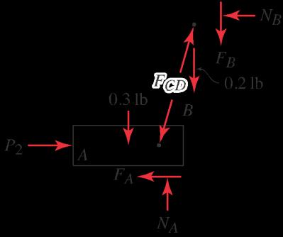
The mechanism for a gumball machine is shown in Figs. P9.26 and P9.27. To begin dispensing a gumball, as shown in Fig. P9.26, a horizontal force P1 is applied to block A to cause it to begin sliding to the right while member CD simultaneously begins to lift door B. After the door B is fully open, as shown in Fig. P9.27, the gumball drops out of the machine. Blocks A and B weigh 0:3 lb and 0:2 lb, respectively, and the weights of member CD and the gumballs may be neglected. The pins at points C and D are frictionless, blocks A and B are a loose fit in their tracks, and all contact surfaces have a coefficient of friction of 0.3. The motion of the blocks is slow enough so that static equilibrium may be assumed.
Determine the value of P1 that will cause block A to begin moving to the right.
Solution
The tracks ensure that neither block can tip. Since the gumballs have negligible weight, we may assume that they apply no forces to block A. Noting that member CD is a two-force member, the FBDs are

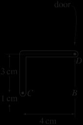

If block A slides, then block B must also slide, and

May 11, 2012 This solutions manual, in any print or electronic form, remains the property of McGraw-Hill, Inc. It may be used and/or possessed only by permission of McGraw-Hill, and must be surrendered upon request of McGraw-Hill. Any duplication or distribution, either in print or electronic form, without the permission of McGraw-Hill, is prohibited. Statics 2e 1370 1370 Solutions Manual
FA D NA D 0:3NA; and FB D NB D 0:3NB : (1) Block B: X Fx D 0 W FCD 3 4 5 NB D 0; (2) X Fy D 0 W FCD 5 0:3NB 0:2 lb D 0; (3) Block A: ) FCD D 0:5555 lb and NB D 0:4444 lb. (4) 3 X Fy D 0 W NA FCD 5 0:3 lb D 0; (5) X Fx D 0 W P1 FCD 4 5 0:3NA D 0; (6)
May 11, 2012 This solutions manual, in any print or electronic form, remains the property of McGraw-Hill, Inc. It may be used and/or possessed only by permission of McGraw-Hill, and must be surrendered upon request of McGraw-Hill. Any duplication or distribution, either in print or electronic form, without the permission of McGraw-Hill, is prohibited. Statics 2e 1371 1371 Solutions Manual ) P1 D 0:6344 lb and NA D 0:6333 lb (7)
Problem 9.27

The mechanism for a gumball machine is shown in Figs. P9.26 and P9.27. To begin dispensing a gumball, as shown in Fig. P9.26, a horizontal force P1 is applied to block A to cause it to begin sliding to the right while member CD simultaneously begins to lift door B. After the door B is fully open, as shown in Fig. P9.27, the gumball drops out of the machine. Blocks A and B weigh 0:3 lb and 0:2 lb, respectively, and the weights of member CD and the gumballs may be neglected. The pins at points C and D are frictionless, blocks A and B are a loose fit in their tracks, and all contact surfaces have a coefficient of friction of 0.3. The motion of the blocks is slow enough so that static equilibrium may be assumed.
Just before the door B is fully opened, as shown in Fig. P9.27, determine the value of P2.
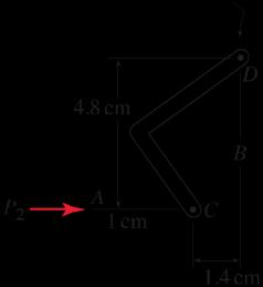
Solution
The tracks ensure that neither block can tip. Since the gumballs have negligible weight, we may assume that they apply no forces to block A Noting that member CD is a two-force member, the FBDs are
If block A slides, then block B must also slide, and

May 11, 2012 This solutions manual, in any print or electronic form, remains the property of McGraw-Hill, Inc. It may be used and/or possessed only by permission of McGraw-Hill, and must be surrendered upon request of McGraw-Hill. Any duplication or distribution, either in print or electronic form, without the permission of McGraw-Hill, is prohibited. Statics 2e 1372 1372 Solutions Manual 5
FA D NA D 0:3NA; and FB D NB D 0:3NB : (1) Block B: X Fx D 0 W FCD 4:8 1:4 5 NB D 0; (2) X Fy D 0 W FCD 0:3NB 0:2 lb D 0; (3) Block A: ) FCD D 0:2283 lb and NB D 0:06393 lb. (4) 4:8 X Fy D 0 W NA FCD X Fx D 0 W P2 FCD 5 1:4 5
