
Part I: Process Design
Chapter 1: Introduction
Chapter 2: Flowsheet development
Chapter 3: Utilities and energy recovery
Chapter 4: Process simulation
Chapter 5: Process control
Chapter 6: Materials of construction
Chapter 7: Estimating capital costs
Chapter 8: Estimating costs of production
Chapter 9: Economic analysis
Chapter 10: Safety
Chapter 11: Plant layout and environmental impact
Chapter 12: Optimization
Part II Plant Design
Chapter 13: Equipment design
Chapter 14: Pressure vessel design
Chapter 15: Reactor design
Chapter 16: Separation processes
Chapter 17: Multistage columns
Chapter 18: Solids handling processes
Chapter 19: Heat transfer equipment
Chapter 20: Plant hydraulics
Note that most of the problems involve design and so have no single unique answer. Credit should be given to students who have followed the right method and found similar solutions. Indeed, the probability of any student independently coming up with the exact answers given in the solution set for more than a few problems should be vanishingly small and this event should cause the grader to be suspicious. The “optimal” solutions presented are usually not numerically optimal and are merely close enough to optimal to be good enough for engineering purposes. This reflects the optimization philosophy described in Chapter 12.
When teaching design, I usually do not give the teaching assistants prepared solutions to the homework problems. I find that if they have to work through the problems themselves they are much better prepared to help the students. They are usually not too happy about it, but it does them good and builds character.
Chapter 1
Problem 1.1
There are many possible correct answers to this question and it can be answered in varying levels of detail. The key steps that should be included for each process with typical required times are listed below. The project plan can be sketched using a spreadsheet or drawn up using a project planning tool such as MS Project (as in Problem 1.2).
a) A petrochemical process using established technology, to be built on an existing site. Since the technology is established, there will be no need to generate design concepts and carry out R&D. The steps are then:
Set design basis (1 week)
Evaluate economics, optimize and select design (typically 10-30 weeks, depending on project scope)
Detailed design and equipment selection (typically six months to one year)
Procurement and construction (typically one year)
Shakedown and start-up (typically one month)
These steps are usually more or less sequential, although some procurement of long lead-time items may be started during detailed design.
b) A process for full-scale manufacture of a new drug, based on a process currently undergoing pilot plant trials. Since the pilot plant is already operating the designer already has a good idea of the process flowsheet and the goal is to be prepared to ramp up production to full scale once the drug is approved. The steps are:
Set design basis (1 week)
Confirm performance/scale-up of pilot plant operations (2-20 weeks, depending on how smoothly pilot plant runs)
Optimize and select design (10-20 weeks)
Detailed design and equipment selection (about six months)
In parallel to these process design activities there will be activities related to getting approval for the new drug:
Conduct clinical trials (6 months to 2 years)
Review clinical trial results (typically 3 to 6 months)
Obtain FDA approval
Some of the procurement and construction activities will be started as soon as the first clinical results look promising, but final construction and shakedown will not occur until the review of clinical trials is completed.
c) A novel process to convert cellulosic waste to fuel. The technology and flowsheet will need considerable development, so a schedule might be:
Set design basis (1 week)
Generate design concepts & carry out R&D (one to five years)
Evaluate economics, optimize and select design (six months, but could run parallel to generating design concepts for up to five years)
Detailed design and equipment selection (six months to one year)
Procurement and construction (about one year)
Shakedown and start-up (one month to one year, as there may be start-up hiccups with a new technology)
d) A spent nuclear fuel reprocessing facility. There is established technology for nuclear fuel reprocessing, but new processes are always possible. For an established technology the schedule would look much like problem (i) and for new technology it would look like problem (iv). All of the steps would probably take longer because of the scale of the plant and additional steps would be needed for obtaining local, state and federal permits and revising them after setting the design basis, selecting the design, and completing detailed design. The time taken to obtain permits could be several years and the total time to operation would probably exceed ten years.
e) A solvent recovery system for electronics production. This is a relatively small project, so the steps would be:
Set design basis (1 – 2 days)
Generate design concepts (1 to 2 months)
Evaluate economics, optimize and select design (ten weeks or less)
Detailed design and equipment selection (2 to 3 months)
Procurement and construction (3 to 6 months)
Shakedown and start-up (one month)
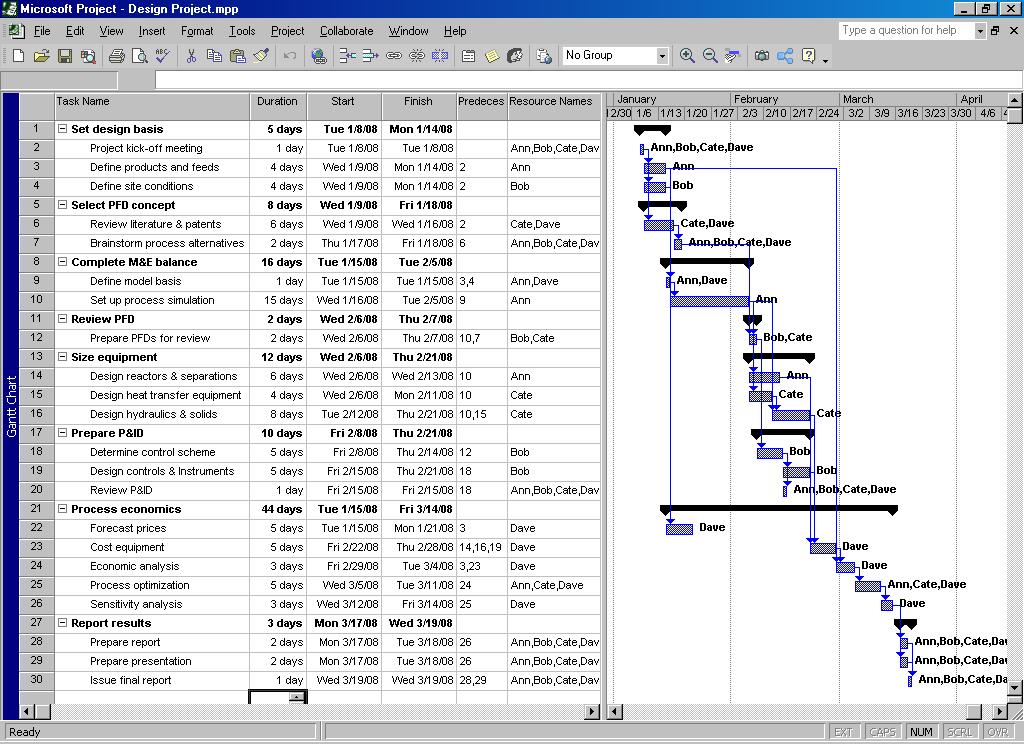
Problem 1.2
This requires a more detailed breakdown than problem 1.1. A sample project plan is given in the lecture slides and shown below (in MS Project format):
Suitable intermediate deliverables could include:
The design basis
A completed PFD (or PFD review)
A completed process simulation
A completed PID (or review)
Problem 1.3
a) The list of product requirements will be somewhat qualitative and depend on the preferences of the “customer” group. The required properties of the dough must consider properties of the dough itself, as well as properties of the final (home-baked) product. Some properties of the dough that might be considered include:
• Shelf life
• Calorie content
• Chocolate chip content
• Stiffness (do you scoop it or is it preformed in cookie shapes?)
• Baking time
Properties of the end cookies are perhaps more obvious:
• Chewiness
• Crunchiness
• Sweetness
• Saltiness
• Mouth feel
• Serving size (if pre-formed)
b) The product specifications could include the following:
• Composition of major ingredients (see any cookie dough: flour, fat or oil, water, etc.)
• Composition of chocolate chips
• Size of chocolate chips
• Composition of minor flavors (salt, vanilla, etc.)
• Composition of baking soda?
• Type and composition of swee
• Type and composition of preservatives, stab
• Type and composition of viscosity modifiers?
• Mixing order
• Mixing time, s
• Dough aging / forming processes
tening agent ilizers peed, temperature (extrusion, cutting, rolling, etc.)
Chapter 2
Solution 2.1
This process can be drawn in more detail, but a simple block-flow diagram is adequate. There may be a need for some heaters and coolers in the plant (e.g. after neutralization), but these are not described in the problem statement and would not need to be shown in a block-flow diagram. Since the process involves batch distillation, it would also be possible to operate the reactor in batch mode and then carry out the neutralization and wash stages in batch mode in the same vessel.
Solution 2.2
This is a continuous process and has a more complex flowsheet incorporating two recycles:
Solution 2.3
This is also a batch process in which some of the extraction steps could be carried out reusing the same equipment. The dashed line shows the reuse of the EDC evaporator to dissolve the product in MeOH for chromatography.
REFORMER
So the average molecular mass = 21.6 kg kmol-1
(ii) At STP, 1 kmol occupies 22.4 m3 Flow rate of gas feed =
Mass flow rate = (156.248)(21.60) = 3375 kg h-1
(iii) Basis: 100 kmol of feed
Reaction (1): CnH2n+2 + n(H2O) → n(CO) + (2n + 1)H2
If the conversion is 96%, then: H2 produced = (380.0)(0.96) = 364.8 kmol
CO produced = (140.0)(0.96) = 134.4 kmol
Reaction (2): CO + H2O → CO2 + H2
If the conversion is 92%, then: H2 from CO = (134.4)(0.92) = 123.65 kmol
Total H2 produced = 364.8 + 123.65 = 488.45 kmol/100 kmol feed
If the gas feed flow rate = 156.25 kmol h-1, then
(Conversion = 97 %)
Basis: 1000 kg RCl feed
(Selectivity = 90 %)
RCl feed = 5.76 1000 = 13.072 kmol
RCl converted = (13.072)(0.97) = 12.68 kmol
ROH produced = (12.68)(0.9) = 11.41 kmol
ROR produced = 12.68 – 11.41 = 1.27 kmol
Mass of allyl-alcohol produced = (11.41)(58.0) = 661.8 kg
Mass of di-ally ether produced = (1.27)(98.0) = 124.5 kg
Solution 2.7
Basis: 100 kmol nitrobenzene feed.
(a, b)
The conversion of nitrobenzene is 96% and so 100(1 - 0.96) = 4 kmol are unreacted.
The selectivity for aniline is 95% and so aniline produced = (96)(0.95) = 91.2 kmol
Therefore, the balance is to cyclohexylamine = 96 – 91.2 = 4.8 kmol
From the reaction equations:
C6H5NO2 + 3H2 → C6H5NH2 + 2H2O
1 mol of aniline requires 3 mol of H2
C6H5NO2 + 6H2 → C6H11NH2 + 2H2O
1 mol of cyclohexylamine requires 6 mol of H2
Therefore, H2 required for the reactions = (91.2)(3) + (4.8)(6) = 302.4 kmol
A purge must be taken from the recycle stream to maintain the inerts below 5%. At steady-state conditions: Flow of inerts in fresh H2 feed = Loss of inerts from purge stream
Let the purge flow be x kmol and the purge composition be 5% inerts.
Fresh H2 feed = H2 reacted + H2 lost in purge = 302.4 + (1 – 0.05)x
Inerts in the feed at 0.005 mol fraction (0.5%) = 005.01
Inerts lost in purge = 0.05x
So, equating these quantities: 0.05x = 1.520 + 4.774 x 10⁻³x
Therefore: x = 33.6 kmol
The purge rate is 33.6 kmol per 100 kmol nitrobenzene feed.
H2 lost in the purge = 33.6(1 – 0.05) = 31.92 kmol
Total H2 feed = 302.4 + 31.92 = 334.3 kmol
Therefore: Total fresh hydrogen feed including inerts = 005.01 3.334 = 336.0 kmol
(c) Composition at the reactor outlet:
Stoichiometric H2 required for aniline = 300 kmol
H2 feed to the reactor = (300)(3) = 900 kmol
Fresh feed H2 = 334.3 and so recycle H2 = 900 – 334.3 = 565.7 kmol
Inerts in Fresh Feed = (334.3)(0.005) = 1.6715 kmol
Inerts in Recycle (at 5%) =
Therefore, total inerts = 1.6715 + 29.77 = 31.445 kmol
Aniline produced = 91.2 kmol
Cyclohexylamine produced = 4.8 kmol
If 302.4 kmol of H2 are reacted, then H2 leaving the reactor = 900 – 302.4 = 597.6 kmol
H2O produced = (91.2)(2) + (4.8)(2) = 192 kmol
2.8
Start by looking at the reaction stoichiometry:
C7H8O2 + C3H6O2 = C10H14O4
Stoichiometric equation balances, so no need to worry about additional components
Molar weights: 124 74 198
a) 100 kg/day of guaifenesin = 100/198 = 0.505 kmol/day
If plant yield is 87% then feed rate = 0.505/0.87 = 0.5805 kmol/day
So glycidine feed rate = 0.5805 × 74 = 42.96 kg/day
guaiacol feed rate = 0.5805 × 124 = 71.982 kg/day