Live Sports Streaming With Prioritized Media-Over-QUIC Transport
»
» Using Single-Pass Look-Ahead in Modern Codecs for Optimized Transcoding Deployment
Ultra-Low Latency OTT Delivery: The Killer Technology for Betting, Social Networking and Metaverse
MOTION IMAGING JOURNAL
» Cloud-Based Internet Linear Video Delivery System Using Edge Computing on a CDN
» And More....
Optimizing Content Delivery
Cutting-Edge Techniques in Live Streaming, Latency Reduction, and Cloud-Based Media Delivery
New Next Generation Tools
Leading the Way in SMPTE ST 2110, Color Conversions, and More!
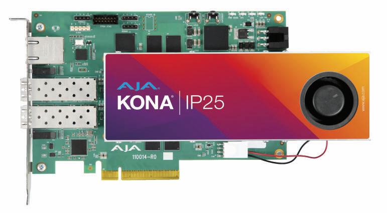
KONA IP25
New SMPTE ST 2110 IP PCIe I/O card supporting bidirectional uncompressed video, with advanced capabilities:
• ST 2110-20 Video: Up to 2 Rx and 2 Tx
• Up to 3840x2160p 60 fps Uncompressed
• ST 2110-30 Audio: Up to 2 Rx and 2 Tx
• Up to 16 audio channels per ST 2110-30 stream
• ST 2110-40 Ancillary: Up to 2 Rx and 2 Tx
• ST 2022-7 Redundancy
• 2x SFP cages: 10 GigE or 25 GigE SFPs
• In-Band and Out-of-Band Control
openGear ColorBox
A new high performance, color management and conversion openGear card, with six unique color processing pipelines:
• 12G-SDI I/O and HDMI 2.0 Out
• Up to 12-bit 4:4:4 4K/UltraHD HDR/WCG
• Ultra-low latency, less than 0.5 of a video line
• Extensive AJA Color Pipeline, 12-bit RGB, with 33-point 3D LUT with tetrahedral interpolation
AJA Diskover Media Edition
v2.3 and new plug-ins for the easy to deploy data management software solution designed to let you nondestructively curate, view and build reports for stakeholders from metadata of your media storage, across your entire organization, regardless of where it is physically located; on-prem, local or remote storage, or in the cloud:
• Plug-in for PixitMedia’s Ngenea data orchestration solution
ST 2110
• Six Color Processing Pipelines: AJA Color, Colorfront (option), ORION-CONVERT (option), BBC HLG LUTs (option), NBCU LUTs, ACES
• HDR signaling metadata management
• 4K Down-convert and Crop
• Built-in Frame Store, Overlay on output
• Embedded web server for remote control
• Plug-in for Spectra Logic’s RioBroker, a media management and archiving platform
• New v2.3 software update featuring a new Administrator UI for control directly within Diskover, and a new integrated PDF Viewer
Winter Intensive IP Networking Professional Boot Camp
November 2024 - January 2025
Don’t miss your chance to join our IP Networking Boot Camp with a specialized focus on SMPTE ST 2110. The program has been designed to support organizations who plan to transition to a full live IP Production environment. Due to high demand for the summer session, we are opening a winter session.
Three Specialized Courses
• Intro to IP Networks (NEW)
• Understanding SMPTE ST 2110 (Updated)
• Designing IP Networks (NEW)
Open Sessions where you can interact with industry experts.
Earn your IP Networking certificate with a focus on SMPTE ST 2110.
Limited to 50 participants.
Members:$999
www.smpte.org/virtual-course/ipbootcamp-winter
MOTION IMAGING JOURNAL
14
INTRODUCTION
Introduction to Optimizing Content Delivery
Jaclyn Pytlarz
Technical Papers
Live Sports Streaming With Prioritized Media-Over-QUIC Transport
Zafer Gurel, Tugce Erkilic Civelek, Ali C. Begen, and Alex Giladi
Enhancing Live Event Production With SDR/HDR Conversion Compatibility and Stable Graphics Management: A Metadata-Driven Approach
David Touze, Frederic Plissonneau, Patrick Morvan, Bill Redmann, Robin Le Naour, Laurent Cauvin, and Valérie Allié
Tutorial
Ultra-Low Latency OTT Delivery: The Killer Technology for Betting, Social Networking and Metaverse
Mickaël Raulet and Khaled Jerbi
Applications/Practices
Using Single-Pass Look-Ahead in Modern Codecs for Optimized Transcoding Deployment
Vibhoothi Vibhoothi, Julien Zouein, François Pitié, and Anil Kokaram
Cloud-Based Internet Linear Video Delivery System Using Edge Computing on a CDN
Daiki Fukudome and Satoshi Nishimura
Enhancements to Media Transport in ICVFX Using SMPTE 2110
Mickaël Raulet and Khaled Jerbi
DEPARTMENTS
10 2024 SMPTE Fellows and Honors and Awards Recipients
13 New SMPTE Standards
73 Memoriam: Charles A. Steinberg
77 Retrospective: Historical Briefs from Past Issues
2024 SMPTE Fellows and Honors and Awards Recipients
The Society of Motion Picture and Television Engineers, Inc., 445 Hamilton Ave., Suite 601, White Plains, NY 10601.
EXECUTIVE
Mike Zink
Education Vice President
Jaclyn Pytlarz Chair/Board of Editors
John Belton
Thomas Edwards
James E. O’Neal
Associate Editors
David Grindle
Executive Director
JOURNAL STAFF
Maja Davidovic Director of Education education@smpte.org
Dianne Purrier Managing Editor, Digital and Print Publications journal@smpte.org
POSTMASTER: Send change of address to SMPTE Motion Imaging Journal, 445 Hamilton Ave., Suite 601, White Plains, NY 10601. All rights reserved. PRINTED IN THE USA
DOI: 10.5594/JMI.2024/DJJG3230
Date of publication: 1 October 2024
SMPTE OFFICERS
OFFICERS
PRESIDENT, 2023–24
Renard T. Jenkins
PAST PRESIDENT, 2023–24
Hans Hoffmann
EBU
EXECUTIVE VICE PRESIDENT, 2023–24
Richard Welsh
Deluxe Media Inc.
STANDARDS VICE PRESIDENT, 2024–25
Sally Hattori
Walt Disney Studios
EDUCATION VICE PRESIDENT, 2023–24
Michael Zink
LG Electronics
MEMBERSHIP VICE PRESIDENT, 2024–25
Rosemarie Lockwood
FINANCE VICE PRESIDENT, 2024–25
Paul Stechly
Applied Electronics
SECRETARY/TREASURER, 2023–24
Lisa Hobbs
MediaKind
EXECUTIVE DIRECTOR
David Grindle
SMPTE Headquarters
DIRECTORS
STANDARDS
Dean Bullock
Florian Schleich
Pierre-Anthony Lemieux
Raymond Yeung
Steve Llamb
Thomas Kernen
EDUCATION
Iris Wu
Monica Brighton
Polly Hickling
MEMBERSHIP
Chris Lapp
John Shike
Zandra Clarke
GOVERNORS
GOVERNORS-AT-LARGE
Chaitanya Chinchlikar
David Long
Jim Helman
John Ferder
Richard Friedel
Stan Moote
Troy English
ASIA/PACIFIC REGION
Michael Day, 2024–2025
Telstra Corporation
Tony Ngai, 2023–24
Society of Motion Imaging Ltd.
CANADIAN REGION
Tony Meerakker, 2024–2025
Meer Tech System
François Bourdua, 2023–24
VS-Tek, Strategies & Technologies
USA - CENTRAL REGION
William T. Hayes, 2023–24
Iowa Public Television
USA - EASTERN REGION
Sara Seidel, 2024–25
Riedel Communications GmbH & Co. KG
Dover Mundt, 2023–24
Riedel Communications
USA - HOLLYWOOD REGION
Eric Gsell, 2023–24
Dolby Laboratories
Marty Meyer, 2023–24
Gravity Media
Kylee Peña, 2024–25
Adobe
EMEA, CENTRAL & SOUTH AMERICA REGION
Fernando Bittencourt, 2023–24
FB Consultant
Dagmar Driesnack, 2024–25
Rohde & Schwarz GmbH & Co. KG
USA - NEW YORK REGION
Thomas Mauro, 2023–24
Media Consultant
USA - SOUTHERN REGION
Frank Torbert, 2024–25
WKMG-TV
U.K. REGION
Chris Johns, 2023–24
Sky UK
USA - WESTERN REGION
Jeffrey F. Way, 2023–24
Quantum
Cassidy Lee Phillips, 2024–25 swXtch.io.
SECTION CHAIRS
ATLANTA
Jack Linder
Linder Consulting
AUSTRALIA
Paul Whybrow
Bodyboard Immersive Experiences
CHICAGO
Jim Skupien
Riedel
DETROIT
R. Thomas Bray University of Michigan
FLORIDA
Shawn Maynard
Florical Systems
GERMANY
No Section Chair
HOLLYWOOD
Marc Zorn
Marvel Studios
HONG KONG
Terence Yiu
Phoenix Satellite Television Co. Ltd.
INDIA
Ujwal Nirgudkar
ITALY
Alfredo Bartelletti
BLT Italia srl
MONTREAL/QUEBEC
Denis Bonneau
Technologie Optic.ca
NEW ENGLAND
Martin P. Feldman
Unique Scientific, Inc.
NEW YORK
John Gallagher
BMCC/CUNY
NORDIC
No Section Chair
OHIO
John R. Owen
Q Communications, LLC
PHILADELPHIA
Mark Mullen
Millersville University
PACIFIC/NORTHWEST
No Section Chair
POLAND
Kamil Rutkowski
Black Photon Sp. z o.o.
ROCKY MOUNTAIN
Sean Richardson
Dolby Laboratories
RUSSIA
Suspended
SACRAMENTO
Bob Hudelson
SAN FRANCISCO
Kent Terry
TEXAS
Curtis Kirk, PlayMate Enterprise LLC
TORONTO
Lawrence St-Onge
LSO Consulting
UNITED KINGDOM
John Ellerton
BT Media & Broadcast
WASHINGTON, DC
Maciej Ochman
Corporation for Public Broadcasting
STUDENT CHAPTERS BY SECTION
ATLANTA
Clark Atlanta University Atlanta, GA
AUSTRALIA
Sydney Student Section Sydney, Australia
DALLAS
Baylor University Waco, TX
CHICAGO
Purdue University
West Lafayette, IN
FLORIDA
Full Sail University Winterpark, FL
University of Central Florida Orlando, FL
GERMANY
Universities of Applied Sciences
Germany (HdM / HSHL / HSRM)
• Hochschule der Medien | Jan Fröhlich
• Hamm-Lippstadt University of Applied Sciences | Stefan Albertz
• RheinMain University of Applied Sciences | Wolfgang Ruppel
HOLLYWOOD
Los Angeles City College
Los Angeles, CA
Media Arts Collaborative Charter
School
Albuquerque, NM
Pasadena City College
Pasadena, CA
USC University of Southern California
Los Angeles, CA
University of Nevada, Las Vegas
Las Vegas, NV
HONG KONG
Hong Kong Design Institute (HKDI)
Hong Kong
Hong Kong Institute of Vocational
Education (IVE)
New Territories, Hong Kong
INDIA
Whistling Woods International Mumbai, India
NEW ENGLAND
Fitchburg State University
Fitchburg, MA
Stonehill College
Easton, MA
NEW YORK
Barnard College
New York, NY
Borough of Manhattan
Community College
New York, NY
Bronx Community College
Bronx, NY
Kingsborough Community College
Brooklyn, NY
New York City College of Technology
Brooklyn, NY
Rochester Institute of Technology
Rochester, NY
Rowan University
Glassboro, NJ
William Patterson University
Wayne, NJ
PHILADELPHIA
Millersville University
Millersville, PA
SAN FRANCISCO
De Anza College
Cupertino, CA
City College of San Francisco & San Francisco State University
San Francisco, CA
TEXAS
University of North Texas
Denton, TX
UNITED KINGDOM
Birmingham City University
Birmingham, U.K.
Ravensbourne
London, U.K.
Southampton Solent University
Southampton, Hampshire, U.K.
University of Salford Manchester, U.K.
University of Surrey
Guildford, U.K.
WASHINGTON, DC
George Mason University
Fairfax, VA
Loyola University
Baltimore, MD
Montgomery College
Rockville, MD
BOARD OF EDITORS
Jaclyn Pytlarz, Chair
loan Allen
Harvey Arnold
John Belton
Steve Bilow
V. Michael Bove
Wayne Bretl
John Brooks
Dominic Case
Curtis Chan
Greg Coppa
Don Craig
Hamidreza Damghani
Michael A. Dolan
Thomas Edwards
John Ferder
Norbert Gerfelder
Brad Gilmer
Keith Graham
Eric Gsell
Randall Hoffner
Tomlinson Holman
Fred Huffman
Kim lannone
Scott Kramer
Sara Kudrle
W. J. Kumeling
Michael Liebman
Peter Ludé
Ian MacSpadden
Andrew H. Maltz
Tets Maniwa
Sean McCarthy
Catherine Meininger
Pavel Novikov
James E. O’Neal
Mark O'Thomas
Karl Paulsen
Kylee Peña
Glen Pensinger
Liz Pieri
Charles Poynton
Adam Schadle
Mark Schubin
Gavin Schutz
Thomas A. Scott
Neil Shaw
James Snyder
Steve Storozum
Stephen A. Stough
Simon Thompson
Paul Thurston
J.B Watson
William Y. Zou
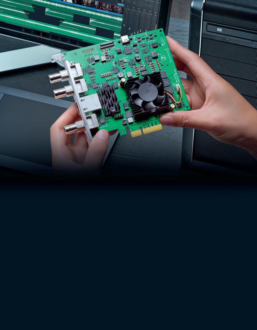
DeckLink IP cards are the easiest way to capture and play back video directly into 2110 IP based broadcast systems! DeckLink IP cards support multiple video channels plus each channel can capture and play back at the same time. You can build racks of servers generating broadcast graphics, virtual sets, or GPU based AI image processing directly integrated into 2110 IP broadcast infrastructure.
10G Ethernet for Multiple SMPTE 2110 IP Channels
DeckLink IP cards conform to the SMPTE ST2110 standard for IP video, which specifies the transport, synchronization and description of video, audio and ancillary data over managed IP networks for broadcast. DeckLink IP supports SMPTE-2110-20 uncompressed video, SMPTE-2110-21 traffic shaping/timing, SMPTE-2110-30 audio and SMPTE-2110-40 for ancillary data.
High Speed 4 Lane PCIe Connection
With a high speed 4 lane PCI Express interface, DeckLink IP cards feature a PCIe connection to the host computer that’s fast enough to handle multiple HD video channels, as well as simultaneous capture and playback on each of the channels. With PCI Express, you get very low latency combined with highly accurate time synchronization to the software that’s capturing or playing video.
Supports All SD and HD Formats up to 1080p60!
DeckLink IP connections are multi rate so they support all SD and HD formats. In S D, DeckLink IP supports both 525i59.94 and 625i50 standards. In H D, DeckLink IP cards support all 720p standards up to 720p60, all 1080 interlaced standards up to 1080i60 and all 1080p standards up to 1080p60. There’s no complex change over as the cards can switch instantly to a new video standard.
Develop Custom Solutions with the DeckLink SDK
Available free with all DeckLink cards is an advanced developer SDK for Mac, Windows and Linux that you can download free of charge! The DeckLink SDK provides low level control of hardware when you need flexibility, as well as high level interfaces which are a lot easier to use when you need to perform more common tasks.
CORPORATE MEMBERS
DIAMOND LEVEL
Apple
Amazon AWS
Blackmagic Design, Inc.
CBS, Inc.
PREMIUM LEVEL
Academy of Motion Picture
Arts & Sciences
ATOS IT Services UK
AVID Technology, Inc.
ADVANCED LEVEL
Absen
AJA Video Systems Inc.
AMD
Belden, Inc.
Bridge Technologies Canon, Inc.
Dell
ESSENTIAL LEVEL
AOTO
Appear AS
Applied Electronics Ltd.
Arista Networks
Arqiva Ltd.
ARRI, Inc.
Astrodesign Inc.
Bridge Technologies
Brompton Technology
Canare
Carl Zeiss AG
CBC Radio Canada
Chambre des Communes
Channel 4 Television
Christie Digital Systems
Cisco Colorfront Cooke Optics
SMALL BUSINESS LEVEL
80-six
Abel Cine Tech
Adder Technology
Adeas, B.V.
AI Media
Amphenol RF
Analog Way
Astrodesign, Inc.
ATEME SA
Australian Institute of Aboriginal & Torre Strait
Islander Studies (aiatsis)
Aveco
Barco
BBC Future Media
Boland Communications
Broadstream Solutions
Castlabs GmbH
Chesapeake Systems
INDUSTRY PARTNERS
Deluxe
Disney/ABC/ESPN
Dolby Laboratories Fox Corporation
Bloomberg
British Telecommunications, PLC
Imagine Communications
Deloitte Consulting
Densitron Technologies
European Broadcasting Union
Fuse Technical Group
Huawei
IMAX Corporation
Creamsource
Dalet Digital Media Systems
Digital TV Group (DTG)
Disguise
Disney Streaming Services
Diversified
Ericsson
Evertz
EVS/Broadcast Equip
Extreme Reach
Florical Systems
Fraunhofer
Gloshine Technology Co., Ltd.
Grass Valley, Inc.
ICVR
Intel Corporation
Koninklijke Philips NV
Leader Electronics Corporation
CineCert
Cobalt Digital
CST (Comission Superiere
Technique de I’image et du son)
Dalet
DekTec America
Deltacast.tv
Digital Video Group, Inc.
Disk Archive Corporation Limited
DSC Laboratories
Eikon Group Co.
Eluv.io
Eviden
Flanders Scientific
Fujifilm Inc.
GDC Technology
Glassbox Technologies
The Helm Technology
Google Paramount Pictures
Ross Video
Sony Electronics, Inc.
Microsoft Corp.
Monumental Sports & Entertainment
NBC Universal
IMG Media Ltd
Interdigital Communications
Library of Congress
Media Solutions)
Mo-Sys Engineering
NEP Group
Novastar
Ledyard/Planar
LG Electronics
Matrox Graphics Inc.
Media Links Co., Ltd.
MediaKind
MediaSilo
Megapixel VR Meinberg-Funkuhren GmbH & Co.
Motion Picture Solutions
MLB Advanced Media
National Association of
Theater Owners
NEC Corporation
Net Insight
Nevion
NHK (Japan Broadcasting Corp.)
IHSE USA LLC
Imagica Entertainment Media Services, Inc.
Innovative Production
Services
InSync Technology Ltd.
Intelligent Wave Inc.
Internet Initiative Japan
IntoPIX
Kino Flo, Inc.
Lapins Bleus Formation
LAWO
Light Field Lab, Inc.
Lynx Technik AG
Macnica Technology
Marquise Technologies
Media Tek Inc.
Metaglue
Metaphysic
Telstra Corporation
Warner Bros. Discovery
Rohde & Schwarz GmbH & Co. KG
Sudwestrundfunk/ARD
Panasonic Corporation
Qube Cinema
Red Digital Camera
Roe Visual Co, Ltd.
Seagate Technology
Signiant
Sky U.K.
Nvidia
ORF - Austrian Broadcasting Corporation
Pebble Beach Systems
Perforce Systems
Pixelogic
Pixotope
Portrait Displays
ProSiebenSat.1 Tech Solutions
GmbH
Quasar Science
Qube Cinema
Riedel Communications
Rosco Laboratories
RTBF
Schweizer Radio und Fernsehen
Sencore, Inc.
Mole-Richardson Co.
Nemal Electronics Intl. Inc.
Netgear AV
The Nielsen Company (US), LLC
NTT Network Innovation Labs
Original Syndicate
Panamorph
Plus 24
Port 9 Labs
Qvest Gmbh
Raysync
Seiko Epson Corp.
Showfer Media LLC
Soliton Systems
Starfish Technologies
Strong Technical Services/
Strong MDI
Sutro Tower, Inc.
CONSULTANT LEVEL
Camplex
Holistic Media Productions
Merrill Weiss Group LLC
Streamland Media/Picture Shop
Texas Instruments
The Studio - B&H
Xperi
SiriusXM Radio, Inc.
SRI International Sarnoff
Studio Central
Synamedia
Synaptics, Inc.
Tag VS Telestream, Inc.
Tunnel Post
Universal Pictures
V-Nova
XR Studios
Yleisradio Oy Zixi
Tajimi Electronics Co., Ltd.
Tamura Corporation
Techex Ltd.
Tedial
Teledyne Lecroy PSG
Telos Alliance
Tokyo Broadcasting System
Television, Inc.
Utah Scientific
Video Clarity, Inc.
Visionular
Vuˉ
Queen's Belfast University
TSL Professional Products Ltd.
Education is more accessible too. Members can access self-study courses at no additional cost, so you can learn at your own pace! In addition, instructor-led classes are available to members at a reduced price. Continue your education with SMPTE!
SMPTE Media Technology Summit:
Embracing Innovation and Preparing for the Future of Media Technology
RENARD T. JENKINS
Hello members, colleagues, and peers, welcome to the fall edition of the Motion Imaging Journal. I hope that your summer was both restful and restorative. At SMPTE, we have been extremely busy preparing for our signature event. This year‘s media technology summit is gearing up to be the best thus far. The session lineup covers the gamut of the most important topics in our industry today. From the essentials of IP architecture to innovations in visual content technology, our presenters are delivering content that is critical to the future of our industry. The committee is comprised of a comprehensive and educational summit. This is one of the last remaining peer-reviewed technical conferences in the media entertainment industry. Because of that fact, we can guarantee that you will leave this event more knowledgeable about the subjects presented. What excites me most about this event each year is that this is the moment when the words and the diagrams of the jour-
nal leap from the pages and into the zeitgeist of our common vernacular. I want to thank all of the individuals who were involved in supporting the summit in any capacity. Your service to the industry and this Society is greatly appreciated.
As I mentioned earlier, our industry is going through tremendous change at a rate that surpasses Moore’s Law. To remain relevant, our Society must continue to change as well. As we look across the slate of our educational offerings, as well as our events and our products and services, we are constantly working to identify areas in which we can increase our focus. IP infrastructure, animation, visual effects, and game engine technology are just a few areas where we have begun to increase our research and participation. With artificial intelligence and machine learning on the minds of everyone in our industry, we feel the Society must be involved in the critical conversations around its use, potential, and need for policies, guidelines, and standards. Therefore, at the recent international
“AS THESE TECHNOLOGIES BECOME AS UBIQUITOUS WITHIN OUR INDUSTRY AS COLOR BARS AND TIME CODE, WE PLAN TO STAY AT THE FOREFRONT OF THE RESEARCH, STANDARDIZATION, AND INTEROPERABILITY EFFORTS.”
broadcaster’s conference in Amsterdam, SMPTE presented a half day of educational sessions focused on these topics. The response from our industry peers has been positive, and we have successfully begun to build new relationships with organizations that we feel will be valuable collaborators as we head into 2025.
Finally, as many know, the Society delivered the SMPTE AI Report in February 2024. Since then, this document has been touted as one of the most comprehensive papers on the subject and its potential impact on media and entertainment. As this is a living document, the Society is in-
DTA-2172
2x 3G - SDI/ASI Low profile Genlock
vested in keeping it updated and relevant for our members and readers across the industry. As these technologies become as ubiquitous within our industry as color bars and time code, we plan to stay at the forefront of the research, standardization, and interoperability efforts. This is our commitment to our members and our industry. Again, thank you to all our volunteers, staff, members, and contributors. Be well.
DOI: 10.5594/JMI.2024/OPEZ3392
Date of publication: 1 October 2024
-2174B
SDI/ASI (1x 12G)
Single or quad-link 4K Genlock
DTA-2178
8x 3G - SDI/ASI (2x 12G)
8x 12G - SDI with scaling Genlock
2024 SMPTE FELLOWS
“A Fellow of the Society is one who has by proficiency and contributions attained an outstanding rank among engineers or executives in the motion picture, television, or related industries.”
Ten members will be inducted as SMPTE Fellows at the Fellows Luncheon on Monday, 21 October at the Loews Hollywood Hotel in Hollywood, CA.
2024 HONORS AND AWARDS RECIPIENTS
The 2024 Awards Gala will take place on Thursday, 24 October, featuring a reception and dinner at the Loews Hollywood Hotel in Hollywood, CA.
HONORARY MEMBERSHIP
DAVID SARNOFF MEDAL
EXCELLENCE IN EDUCATION MEDAL
DIGITAL PROCESSING MEDAL
CAMERA ORIGINATION AND IMAGING MEDAL
WORKFLOW SYSTEMS MEDAL
Naveed Aslam Vice President, Technology and Engineering, CBS/ Paramount
Michel Proulx Principal Advisor, Independent Consultant
Alexandre Rouxel Sr Project Manager, Data and AI, European Broadcasting Union (EBU)
Gene J. Zimmerman Jr., CEO, President, Cobalt Digital Inc.
Peter Brightwell Lead R&D Engineer, British Broadcasting Corporation (BBC)
Brian Quandt CTO, AutoDCP
Paola Sunna Senior Technology and Innovation Manager, Eurovision Italy/EBU
Alexander Forsythe Sr. Director, Science and Technology, Academy of Motion Picture Arts and Sciences
Pierre-Hughes Routhier Media Production Architect, Canadian Broadcasting Corp.
Stuart C. Young Senior Solutions Engineer, Television New Zealand Ltd.
Ioan Allen Senior Vice-President, Dolby Laboratories
John Mailhot SVP Product Management, Imagine Communications
Unreal Engine
Chaitanya Chinchlikar Vice President & Business Head, Chief Technology Officer & Head of Emerging Media, Whistling Woods International
Takashi Nakamura (Posthumous)
Jens-Rainer Ohm Chaired Professor, Director of Institute, RWTH Aachen University, Institute of Communication Engineering
Franz Kraus Advisor, ARRI (Retired)
JAMES A. LINDNER ARCHIVAL TECHNOLOGY MEDAL
JOURNAL
AWARD
JOURNAL CERTIFICATE OF MERIT
EXCELLENCE IN STANDARDS AWARD
PRESIDENTIAL PROCLAMATION
CITATION FOR OUTSTANDING SERVICE TO THE SOCIETY
LOUIS F. WOLF JR. MEMORIAL SCHOLARSHIP STUDENT PAPER AWARD
Ievgen Kostiukevych Team Leader, Media over IP and Cloud Technologies, EBU
Erik Reinhard Distinguished Scientist, InterDigital
Michael Frank Day Product Manager, Professional Media, Telstra
Marina Kalkanis Co-founder and CEO (retired), M2A Media
Reshma Saujani Founder and CEO, Moms First; Founder, Girls Who Code
Lanny Smoot Disney Research Fellow, The Walt Disney Company, Walt Disney Imagineering Thorsten Lohmar, Expert, Media Delivery, Ericsson
Karen Cariani
David O Ives Executive Director, GBH Archives WGBH Educational Foundation
Paul Treleaven Technology Consultant, IABM
Gabriel Casselman Student, Rochester Institute of Technology
Irene Muñoz López Multi-Skilled Operator, Vision, Vivid Broadcast Ltd. (University of Surrey U.K., when paper was submitted)
Photo not available
What’s New for Members in 2024!
With membership, you will also have access to the new and improved SMPTE Motion Imaging Journal, one of the most valuable publications in the media technology industry—Easier to access and read, both print and online issues. You can experience the journal like never before!
NEW AND UPCOMING:
SMPTE Standards
The following standards were recently published/revised:
ST 2067-70:2024, Interoperable
Master Format — Application SMPTE
ST 2019-1 (VC-3): Published September 3, 2024. This is a new standard.
DOI: 10.5594/JMI.2024/HHHX4138
Date of publication: 1 October 2024
ST 2082-1:2023, 12 Gb/s Signal/Data
Serial Interface — Electrical: Published July 23, 2024. This is a revision of an existing standard.
ST 2081-1:2023,. 6 Gb/s Signal/ Data Serial Interface — Electrical: Published July 22, 2024. This is a revision of an existing standard.
Introduction: Optimizing Content Delivery
BY JACLYN PYTLARZ
Welcome SMPTE readers to our final technical paper issue of the 2024 season. We are wrapping this year up with a mixed issue. Most of our technical papers will cover improvements and proposals for ultra-low latency encoding and live-streaming applications. Our two off-topic papers on this issue will cover new HDR/SDR dynamic conversion methods with metadata and in-camera visual effects improvements utilizing SMPTE ST 2110. Here’s a brief snippet for each of the papers you’ll find in this issue:
“Live Sports Streaming with Prioritized Media Over-QUIC Transport:” This paper explores the innovations in streaming prioritization. The authors present experimental results on latency for frame-typebased (I-frame, B-frame, P-frame) prioritization and show how the same on-time display ratio can be achieved with lower latency budgets if we apply a better prioritization scheme.
“Enhancing Live Event Production with SDR/HDR Conversion Compatibility and Stable Graphics Management: A Metadata-Driven Approach:” This paper recommends a new SDR/HDR tone mapping method. It shows how a dynamic methodology can produce higher
image quality results and proposes metadata to define the tone mapping curve for improved interoperability. In addition, it outlines a tone mapping adjustment that could help achieve more stable graphics when doing a dynamic down-conversion.
“Ultra-Low Latency OTT Delivery: The Killer Technology for Betting, Social Networking, and Metaverse:” This paper explores the landscape of ultra-low latency streaming for over-the-top (OTT) live applications. It includes a solid introduction to methodologies in practice today. In addition, the authors propose a method to reduce encoder-to-playout latency down to 1.7 seconds using encoder, packager, and network optimizations.
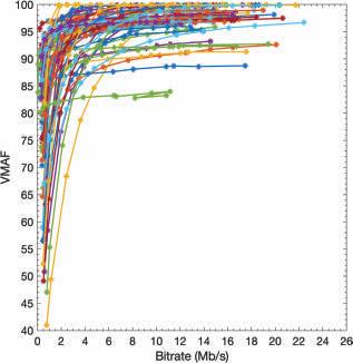
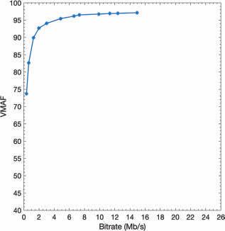
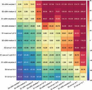
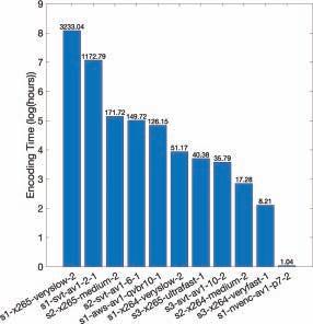
“Using Single-Pass Look-Ahead in Modern Codecs for Optimized Transcoding Deployment:” This
paper evaluates the performance and quality impacts of using production-ready single pass encoders for video-on-demand use cases. It aims to show how this single-pass workflow can significantly decrease transcoding time and complexity while maintaining high perceptual quality.
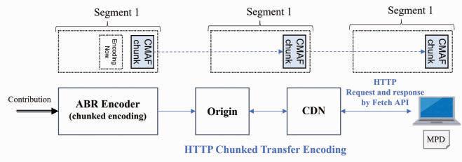
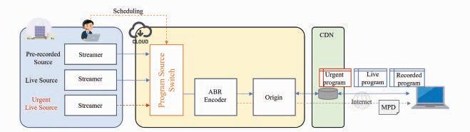
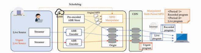
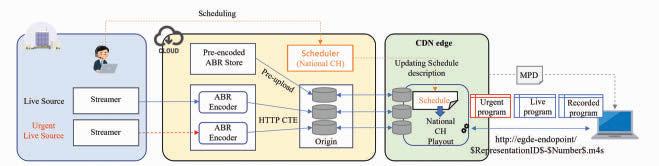
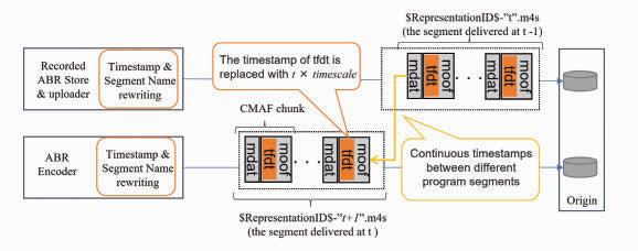
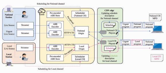
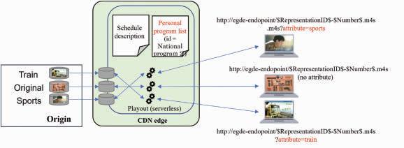
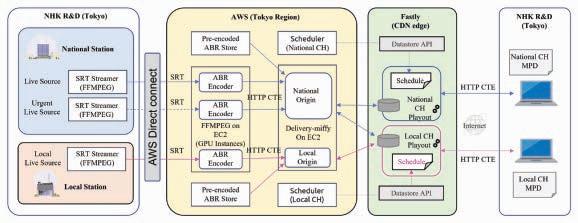
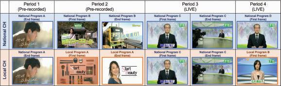
“Cloud-Based Internet Linear Video Delivery System Using Edge Computing on CDN:” This paper proposes a cloud-based HTTP adaptive-streaming workflow that uses edge computing within the content delivery network (CDN) to facilitate prompt schedule changes. The authors show how this methodology can improve latency and complexity for live-linear streaming to deliver localized and personalized channels.
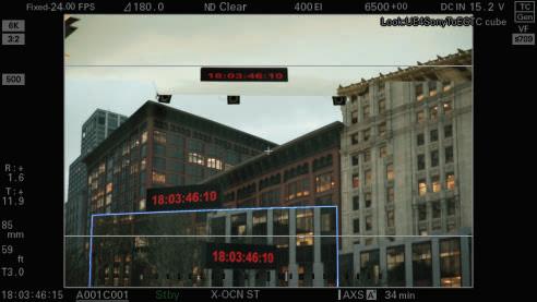
“Enhancements to Media Transport in ICVFX using SMPTE 2110:”
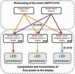
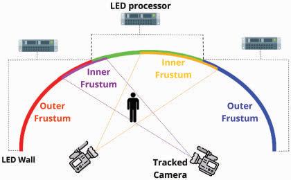
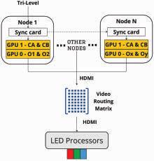
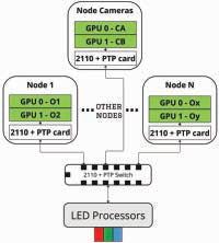
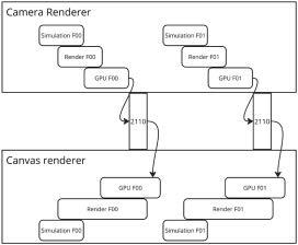
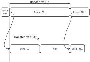
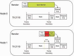
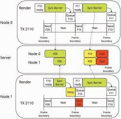
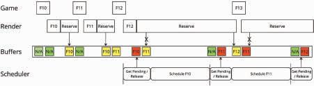
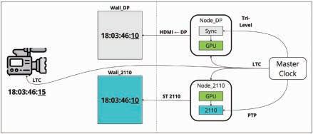
This paper provides a thorough proposal including experimental results for utilizing SMPTE 2110 in the clustered rendering pipeline for in-camera visual effects. The authors show how 2110 can be used to multi-cast multiple camera views to the render nodes and how the final pixels can be output to synchronously drive each section of the LED walls used on set.
I hope you thoroughly enjoy this issue of the SMPTE Motion Imaging Journal. As always, happy reading!
About the Author
Jaclyn Pytlarz is a senior staff researcher at Dolby Laboratories in Sunnyvale, CA, where she leads Dolby’s Vision Science research organization. She also chairs the SMPTE Board of Editors.
DOI: 10.5594/JMI.2024/EVMX1100
Date of publication: 1 October 2024
Elevate your content with AI-Media’s cutting-edge solutions
AI-Media, a global leader in AI-powered captioning, enhances accessibility with deep industry expertise. We deliver top-quality live and recorded captioning and translation solutions to broadcasters, enterprises, and government agencies worldwide. Gold standard caption encoder for SDI and IP solutions, including SMPTE 2110 AI-Powered LEXI Automatic Captions
20+ years in-field experience
Trusted by major broadcasters and organizations globally
Turnkey solutions for any workflow
Future-proof captioning solutions
Live and VOD captions
Multilingual captions and translation
TECHNICAL PAPER
Live Sports Streaming With Prioritized Media-Over-QUIC Transport
By Zafer Gurel, Tugce Erkilic Civelek, Ali C. Begen, and Alex Giladi
QUIC-based transport for media delivery provides a groundbreaking approach to low-latency streaming, enabling prioritized content transmission and reducing delays. By leveraging QUIC’s unique features, such as stream multiplexing and prioritization, media applications can achieve better performance, ensuring timely delivery and an enhanced viewing experience across various use cases, including live sports and cloud gaming.
KEYWORDS LIVE STREAMING // DASH // QUIC // MOQT
Abstract
A QUIC-based low-latency delivery solution for media ingest and distribution in browser and non-browser environments is currently being developed for various use cases such as live streaming, cloud gaming, remote desktop, videoconferencing, and eSports. Operating in an Hyptertext Transfer Protocaol (HTTP)/3 environment (i.e., using WebTransport in browsers) or using raw (Quick UDP Internet Connection) QUIC transport, QUIC can revolutionize the media industry, overcoming the limitations we face with the traditional approaches that impose TCP. This study explains the design methodology and explores possible gains with QUIC’s stream prioritization features.
Live sports broadcasting, where fans can stream live content on their connected devices, or cloud gaming, where users can play together connecting from different parts of the world, has many demanding requirements. Nobody wants to hear a neighbor’s cheers when a goal is scored before seeing it on the screen, making low-latency transport and playback indispensable. Similarly, high latency is intolerable when playing games in the cloud.
The existing HTTP ecosystem comprises solid foundational components such as distributed caches, efficient client applications, and high-performing server software glued with HTTP. This formation allows efficient live media delivery at scale. However, the two popular approaches, Dynamic Adaptive Streaming (DASH) and HTTP Live Streaming (HLS), are highly tuned for HTTP/1.1 and 2 running on top of Transmission Control Protocol (TCP).1,2 The downside is the latency caused by the head-of-line (HoL) blocking experienced due to TCP’s in-order and reliable delivery. The latest version of HTTP (HTTP/3) uses QUIC (specified in RFC 9000) underneath instead of TCP. QUIC can carry different media types or parts in different streams. These streams can be multiplexed over a single connection, avoiding the HoL blocking.1,3 The streams can also be prioritized (or discarded) based on specific media properties (e.g., dependency structure and presentation timestamp) to trade off reliability with latency. DASH and HLS can readily run over HTTP/3, but they can only recoup the benefits using its unique features.4
In the Internet Engineering Task Force (IETF), a new working group, Media over QUIC (MOQ), was formed in 2022 to study further the possible enhancements that QUIC may bring for low-latency live streaming.5 The initial implementation of MOQ Transport (MOQT) is discussed during the IETF meetings, which is on its way to standardization.6 As the initial discussions reveal, MOQT may improve the scalability of real-time, interactive media applications and the interactivity of live-streaming applications.
This paper explains the MOQT design considerations and summarizes the enhancements we implemented in a previous study.7,8 Then, we investigate the prioritization schemes that can be performed over this first implementation and show results for the on-time-display ratio under different bandwidth constraints.
MOQT Design Methodology
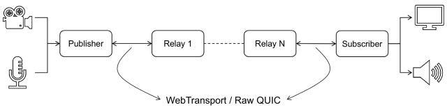
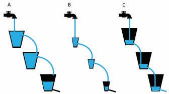
MOQT offers a latency-configurable delivery protocol for transmitting content from one or more senders to the receiver(s) over zero or more relays utilizing either WebTransport (in browsers) or raw QUIC (otherwise), as shown in Fig. 1. Relays scale media delivery by forwarding incoming media to one or more relays or receivers without requiring a unique encoding for every recipient. To adapt to congestion and meet the application’s latency requirements, relays choose what to deliver in what order or what to drop, depending on the particular metadata disclosed in the envelope of the incoming packets. Receivers can also compromise on quality and latency by determining the ideal time to wait for media, depending on their network conditions and user expectations.
The server side of the first MOQT demo (initially named Warp) uses a customized quic-go library with features like stream prioritization and Application Programming Interface (APIs) that expose the bandwidth and QUIC connection.9 The server mimics live streaming by releasing a pre-encoded and pre-packaged media file chunk by chunk as soon as a client connects. In this implementation, each media frame is packaged as a CMAF chunk using the Common Media Application Format (CMAF, ISO/IEC 23000-1910) standard.
The client application is a Web page that plays the live feed, includes a video element, and establishes a connection to the server using the WebTransport API after the page has loaded and begins to receive QUIC streams. The CMAF segments are parsed and appended to the source buffer as
they are received. The client uses a unidirectional, single QUIC stream to send the server control messages (such as play, pause, and resume).
Enhancements to MOQT Demo
The first MOQT demo provided the necessary elements, but numerous others were required for a complete study. The improvements we made to create a testbed for experimenting with MOQT proposals are outlined below8 and can be reached at:11
• addition of data keys under server-to-client informational messages to calculate end-to-end latency on the client side and throughput estimation on the server side,
• wall-clock time synchronization between the server and client,
• addition of client-to-server control messages for transmitting client preferences to the server,
• addition of passive and active bandwidth measurement methods and
• enhanced user interface to compare the real-time bandwidth measurements on both sides.
Prioritization Schemes
Prioritization is an important feature yet to be studied by the IETF MOQ working group. The network usually cannot maintain the intended order for media content – the order to decode the material and play it. Due to several reasons, a receiver cannot expect packets to be received in the order
they were sent. The sending of specific streams may be delayed by packet loss or flow control.
Latency budget is the maximum acceptable delay between when a media unit is generated and when it will be consumed in a given application. The latency budget allows a client to buffer and re-order the incoming and possibly out-of-order packets for decoding. This, in turn, smooths the viewer experience by avoiding frame drops and increasing the on-time-display ratio (of the frames).
The ideal latency budget differs from application to application. For instance, the quality of experience is directly tied to the end-to-end latency for live sports. Therefore, a lower latency budget should be used for low-latency delivery applications. Aiming for high-quality streaming using a small latency budget is a challenging task. It requires careful planning of each step in the streaming process, from encoding to transmission to decoding. Each step’s small latency gain helps keep the latency budget low. Using a tool such as prioritization can make a difference.
Developing effective prioritization techniques for different types of applications is possible with MOQT. For low-latency live streaming, an approach may be to group I and P-frames with a higher priority than B-frames. For non-low-latency live streaming, high-resolution frames can be prioritized over low-resolution frames. Prioritization should not be limited to just the type of frames. For example, a user can also be given the option to choose to prioritize low latency over high quality or vice versa.
FIGURE 1. Simplified end-to-end deployment of MOQT.
FIGURE 2: Illustration of implicit prioritization without congestion.
The current MOQT draft6 describes two prioritization options (Send Order and Ordering with Priorities), and in this study, we explore and compare the following two schemes.
Implicit Prioritization
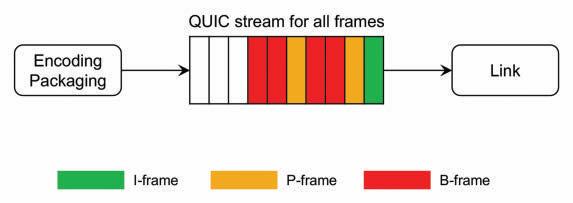
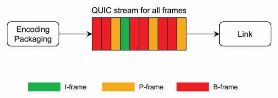
The video frames are transmitted without specific prioritization in the delivery process. A single unidirectional QUIC stream is used to deliver the frames, and their send order is the same as their encoding order. This Implicit Prioritization is also called First Encode, First Send (FEFS). The delivery order is the same as the send order because QUIC guarantees the delivery order for the objects sent over the same stream, as illustrated in Fig. 2. Nonetheless, in cases where there is congestion on the link or not enough available bandwidth to
send all the frames (e.g., see Fig. 3), queueing will occur, and later frames will experience an increased delay.
Prioritization by Frame Type
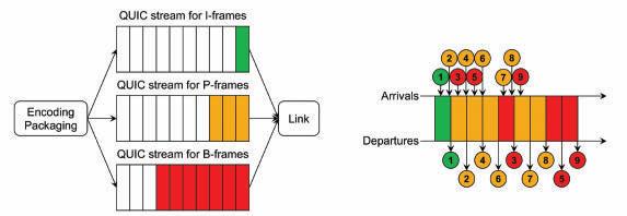
The video frames are prioritized according to their types (e.g., I, P, and B). For each frame type, a separate unidirectional QUIC stream is created, and each stream is assigned a priority based on that type (as illustrated on the left in Fig. 4), where the I-frames and B-frames have the highest and lowest priority, respectively. This way, it is expected that in a congested network, the timely delivery of I-frames is more likely than that of P and B-frames. The timely delivery of P-frames is also more likely than B-frames (as illustrated on the right in Fig. 4).
FIGURE 3. Illustration of implicit prioritization with congestion.
FIGURE 4. Illustration of prioritization by frame type.
FIGURE 5. Calculation of the on-time-display ratio (OTDR) metric.
Experiments And Results
Experimental Setup
We ran several experiments with different configurations to compare the prioritization schemes. These experiments were conducted on a computer with an Intel Core i7-8750H CPU (6 cores, 12 threads) and 32 GB of RAM, running Ubuntu 22.04.2 LTS with a kernel version 5.15.0. Node.JS and NPM versions were 18.13 and 9.3.1, respectively. The Go runtime version was 1.19.5. As the browser, Chrome 113.0.5672.63 was used to run the MOQT demo. For network emulation (e.g., applying a bandwidth constraint), tc NetEm was used.
We used a pre-encoded (1280 x 720) test video to simulate live streaming. It was displayed for approximately two minutes in each experiment. The frame rate was 25 frames per second (fps), and the group-of-pictures (GoP) length was 50 frames (two seconds). Each frame was packaged into a CMAF chunk, and each GoP was packaged into a CMAF fragment. The GoP structure was a sequence of frames where two B-frames were interleaved between the I and P-frames (i.e., IBBPBBP…).
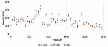
The bitrate of the test video with the associated overheads was approximately 2.7 Mbits/s. Therefore, the frame latency variations were measured at three bandwidth constraints: 2.7, 2.85, and 3 Mbits/s.
Performance Metrics
The metrics to evaluate the effectiveness of the prioritization are (i) latency variation depending on the bandwidth con-
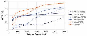
straint and (ii) the on-time-display ratio (OTDR) under different latency budgets. OTDR indicates the ratio of the number of frames displayed on time over the total number.
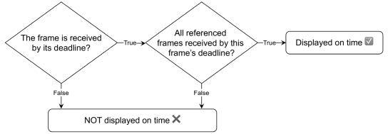
In multimedia applications, not all the received frames are necessarily displayed on time. A P-frame can be displayed only if the I-frame and any other preceding P-frame have been received. Similarly, B-frames can be displayed only if the referenced I and P-frames have been received.
When determining whether a frame is displayed on time, it is checked whether the frame(s) it depends on are received and decodable by this frame’s presentation deadline. The methodology is summarized in the flowchart given in Fig. 5.
FIGURE 6. Latency variation for I-frames.
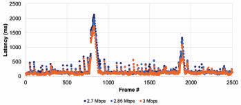
FIGURE 8. Latency variation for B-frames.
FIGURE 7. Latency variation for P-frames.
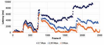
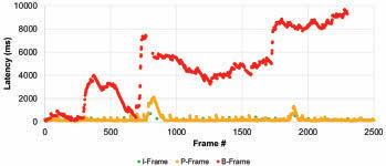
FIGURE 9. Latency variation for all frames at a bandwidth constraint of 2.7 Mbits/s.
FIGURE 10. OTDR with FEFS and FT prioritization schemes.
Results
In the tests, we measured the latency for different frame types, which were prioritized differently. Figs. 6, 7, & 8 present the individual latency values for the I, P, and B-frames, respectively. First, while the results show a latency variation among the frames of any given type, the variation is smallest for the I-frames and largest for the B-frames. At the same time, the latency variation among the I and P-frames does not change between the scenarios of bandwidth being constrained to 2.7 Mbits/s vs. 3 Mbits/s. On the other hand, the latency variation for the B-frames increases substantially when the bandwidth is constrained more. These are expected as prioritization limits the impact of the network congestion and the amount of latency experienced. Fig. 6 also shows that if the latency budget is 700 ms or more, all I-frames can be displayed on time. At this latency budget (700 ms), Fig. 7 reveals that some P-frames will not be displayed on time, and Fig. 8 reveals that most B-frames will not be displayed on time.
Figure 9 reveals the latency variation of all frame types when the bandwidth is constrained to 2.7 Mbits/s. We observe that latency values for the I and P-frames vary in a smaller range. In contrast, the variation for the B-frames is significantly larger.
Figure 10 shows the OTDRs for different bandwidth constraints under a latency budget of up to 3000 ms. While calculating the OTDR (of all frames of all types), the main idea is to check whether any given frame is received and can be displayed within that latency budget. The dashed lines illustrate the OTDRs with implicit prioritization (First Encode, First Send – FEFS). The dashed lines also represent the OTDR performance if we had used a single TCP connection (rather than one QUIC stream in a single QUIC connection). On the other hand, the solid lines illustrate the OTDRs with prioritization by frame type (FT) (using three QUIC streams in a single QUIC connection). The results show that MOQT enables us to improve the OTDR performance through better prioritization under the same bandwidth constraint. Said differently, the same OTDR performance can be achieved with lower latency budgets if we apply a better prioritization scheme.
Conclusion
MOQT is currently under development, and it potentially comes with many advantages. With the enhancements we implemented to MOQT,12 we can provide the client with better performance under the same resources. For low-latency use cases, prioritization always provides higher OTDRs, resulting in a better quality of experience or a fairer use of available resources. The next step in our research is to expand the testing to multi-client scenarios.
References
1. S. Arisu and A. C. Begen, “Quickly starting media streams using QUIC,” ACM Packet Video Wksp., 2018, doi:10.1145/3210424.3210426
2. R. Pantos, Ed. HTTP live streaming 2nd edition. Accessed on June 1, 2023. [Online]. Available: https://datatracker.ietf.org/doc/draft-pantos-hls-rfc8216bis/
3. T. Shreedhar, R. Panda, S. Podanev, and V. Bajpai. Evaluating QUIC performance over web, cloud storage, and video workloads. IEEE Trans. Network and Service Management, Jun. 2022.
4. M. Nguyen, C. Timmerer, S. Pham, D. Silhavy, and A. C. Begen. Take the red pill for H3 and see how deep the rabbit hole goes. In ACM MHV, 2022. doi:10.1145/3510450.3517302
5. Internet Engineering Taskforce (IETF). Media Over QUIC (moq). Accessed on June 1, 2023. [Online] Available: https://datatracker.ietf.org/wg/moq/about/
6. L. Curley, K. Pugin, S. Nandakumar, and V. Vasiliev. Media over QUIC Transport. Accessed on June 1, 2023. [Online]. Available: https://datatracker.ietf.org/doc/ draft-lcurley-moq-transport/
7. Z. Gurel, T. E. Civelek, and A. C. Begen. Need for low latency: media over QUIC. In ACM MHV, 2023. doi:10.1145/3588444.3591033
8. Z. Gurel, T. E. Civelek, A. Bodur, S. Bilgin, D. Yeniceri, and A. C. Begen. Media over QUIC: initial testing, findings, and results. In ACM MMSys, 2023. doi:10.1145/3587819.3593937
9. Luke Curley. kixelated/warp-demo: Demo server and web player for the Warp live video protocol. Accessed on May 1, 2023. [Online]. Available: https://github.com/ kixelated/warp-demo
10. International Organization for Standardization/International Electrotechnical Commision (ISO/IEC) 23000-19:2020 Information technology—Multimedia application format (MPEG-A)—Part 19: Common media application format (CMAF) for segmented media. Accessed on Jun. 1, 2023. [Online] Available: https://www.iso. org/standard/79106.html
11. Streaming University. streaming-university/public-moq-demo: MOQ testbed. Accessed on June 1, 2023. [Online] Available: https://github.com/streaming-university/public-moq-demo
12. Zafer Gurel, Tugce Erkilic Civelek, Deniz Ugur, Yigit K. Erinc and Ali C. Begen. Media-over-QUIC transport vs. low-latency DASH: a deathmatch testbed. In ACM MMSys, 2024 doi: 10.1145/3625468.3652191
About the Authors
Zafer Gurel is a computer science PhD candidate at Ozyegin University under the supervision of Prof. Dr. Ali C. Begen as well as the co-founder and CTO of Perculus which is an ed-tech start-up developing a video conferencing tool for instructors.
Tugce Erkilic Civelek holds bachelor’s and master’s degrees in electrical and electronics engineering from Middle East Technical University. She has several years of experience as a system design engineer, leading communication projects at ASELSAN, a large-scale technology company in Türkiye.
Ali C. Begen is currently a computer science professor at Ozyegin University and a technical consultant in Comcast’s Advanced Technology and Standards Group. Previously, he was a research and development engineer at Cisco. More details are available at https://ali.begen.net
Enhancing Live Event Production With SDR/HDR Conversion Compatibility and Stable Graphics Management: A
Metadata-Driven Approach
By David Touze,
Given that static 3D-LUTs have characteristics that differ from one to another and further from dynamic conversion techniques, it is a problem that there is no signaling mechanism to identify attributes of HDR content (Diffuse White levels, NFR levels). Thus, there is no mechanism to reliably or automatically select an appropriate HDR-toSDR down-conversion, static or dynamic. KEYWORDS
Frederic Plissonneau, Patrick Morvan, Bill Redmann, Robin Le Naour, Laurent Cauvin, and Valérie Allié
Abstract
Live production, particularly for sports, increasingly employs high dynamic range (HDR) single-master workflows to deliver high-definition (HD), ultrahigh-definition (UHD), standard dynamic range (SDR), and HDR, with graphics insertion extensively used for presenting scores and analytic overlays. The workflows are complex: As content originates as HDR or SDR, conversions between formats are required, and graphics must consistently appear. Static Look-Up Tables (LUTs) are the chief conversion technique used today, though dynamic conversions are available, too. The problem is that each of these conversions produces content with different properties, and none are fully interoperable: Each requires different conversions to deliver a consistent final product. This paper presents a metadata-based solution that resolves the compatibility issue. We present an implementation of this proposal and provide tools that ensure viewers enjoy the highest HDR video quality without compromising the SDR stream. While leveraging the already-acknowledged benefits of dynamic conversion, a new constraint, a specific Static Diffuse White, allows stable graphics management and provides compatibility with existing static LUT workflows, offering resolution to their shortcomings and paving the way for a smooth transition from static to dynamic conversions and single-master delivery of premium HDR and SDR content.
In a prior issue of the Motion Imaging Journal, we discussed challenges for high dynamic range (HDR) and standard dynamic range (SDR) production, focusing on an accurate SDR-HDR-SDR roundtrip.1
HDR has become mainstream in live sports, and the industry must consider how workflows should adapt. The trend is toward HDR single-master production, which involves SDR-to-HDR up-conversions for SDR content to be included in an HDR production. Then, while SDR delivery remains important in the market, it is mandatory to seamlessly down-convert the master HDR signal to provide the SDR feed.
The community recognizes that content shot in HDR can be exceptionally high-quality. There is a growing consensus that the best way to preserve this quality is to shoot without
constraints, capture as much detail and lighting variance as possible, and then apply an effective conversion to derive the SDR content. However, some challenging issues must be addressed when producing SDR streams in this way.
While static conversions based on 3D look-up tables (LUTs) are currently the most used solution, multiple stakeholders must carefully implement the workflow designated for each event.
In this paper, we first recount the main characteristics of static LUTs and dynamic solutions and analyze their interoperability issues.
Second, to improve single-master workflows at each down-conversion step, we propose a set of metadata that characterizes produced or up-converted HDR streams and the targeted down-converted SDR stream.
Third, we provide guidelines for determining a bestchoice conversion method based on the new metadata set. We also show how to exploit the advantages of dynamic conversion yet preserve interoperability with static LUTs when used in a workflow’s up-conversion steps.
Fourth, because graphic inserts represent a constraint in single-master workflows, they must be managed appropriately and remain stable in the down-converted SDR output. This is crucial in live sports production, as graphics are extensively used for scores and analytic overlays.
Lastly, we report on tests of a dynamic down-conversion solution that provides stable graphics management and compatibility with static conversions.
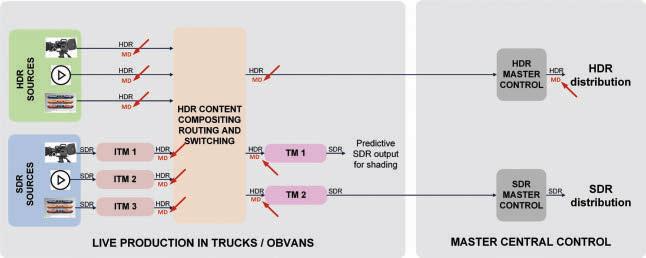
Live Production to Deliver HDR and SDR Programs
Single-Master HDR/SDR Workflow
These are still the early years of HDR production, and there is a transition period during which HDR content and SDR content are delivered to end users. During this transition, simultaneous HDR and SDR production is needed.
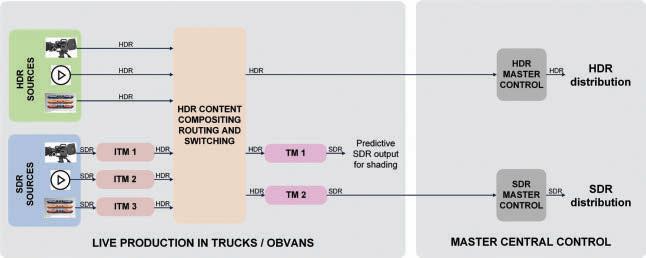
The strongly-motivated trend is to produce in HDR and derive the SDR version automatically. Report ITU-R BT.24082 offers guidance for operational practices to program makers and broadcasters and describes two implementations in section 7.1 and annex 10. This is commonly referred to as a single-master HDR-SDR workflow and is shown in a high-level representation in Fig. 1
A program distributed in HDR is a hybrid of native HDR content (from live HDR cameras or HDR post-production) and other types of content, such as from SDR cameras, advertisements, and graphics for logos and scores. Most of the
time, the sources of these other contents are SDR and must first undergo conversion to HDR before mixing.
Two different conversions are employed in the single-master workflow:
• Up-conversion to convert SDR content into HDR content for inclusion in the HDR program.
• Down-conversion to convert HDR content into SDR content for distribution.
These conversions are based on dynamic or static solutions, e.g., using 3D-LUTs.3
Guidelines Used In The Industry Reference Levels
The ITU-R BT.24082 report defines various reference signal levels, perhaps the most important of which is the HDR Reference White, also known as HDR Diffuse White, prescribed at 203 cd/m2.
Practically speaking, this HDR Diffuse White level distinguishes between the:
• Primary scene—all important details corresponding to luminances below the HDR Diffuse White level.
• Specular highlights—very bright pixels, generally close to white, that convey few important details, corresponding to luminances above the HDR Diffuse White level.
Annexes 1 and 2 of BT.2408 provide analyses of some already-produced HDR content and strongly suggest that actual HDR diffuse white levels are subject to dynamic adjustments.
Static 3D-LUTs embody implicit static Diffuse White levels for both SDR and HDR content, while dynamic conversions commonly use a dynamic Diffuse White level.
When down-converting HDR-to-SDR using a static solution, the HDR Diffuse White value (e.g., 203 cd/m2) is always mapped to a consistent SDR Diffuse White value (e.g., 86 cd/ m2).
Use of “Sub-black” and “Super-Whites” levels
Recommendations ITU-R BT.709-64 and ITU-R BT.2100-25 describe the YCbCr representations used for video signal ex-
change and define the quantization levels for the common “Narrow Range,” also known as Legal Range, Nominal Range, Normal Range, and herein abbreviated as “NR.” For instance, when using 10-bit quantization:
• Luminance value Y is defined between 64 (black) and 940 (white).
• Chrominance values Cb and Cr are defined between 64 and 960.
However, ITU-R BT.709-6 and ITU-R BT.2100-2 allow video data values from [4-1019], with some justification given in section 2.4 of ITU-R BT.2408 and EBU R-103 recommendation.6 EBU R-103 recommends not exceeding a preferred range of [20-984] for luminance.
Some implementations follow neither the ITU nor EBU recommendations and instead use another range between [4-63] and [941-1019].
We define the use of all or part of the [4-63] and [941-1019] ranges as “Narrow Full Range,” herein abbreviated as “NFR.” The [4-63] range supplies the “sub-blacks,” and the [941-1019] range is the “super-whites” of ITU-R BT.2100-2.
Static 3D-LUTs and dynamic implementations typically use these sub-black and super-white ranges for extra dynamic range.
Static Conversions
Static conversions, implemented by 3D-LUTs, are the chief conversion technique used today. An advantage is that a fixed, well-known conversion should be easily reproducible. A disadvantage is that, as there is no adaptation to the content, static conversions tend to constrain the characteristics of HDR, thereby limiting artistic intent and undermining the potential “Wow” effect of HDR technology.
The variety of 3D-LUTs, each behaving differently, is already wide:
• BBC 3D-LUTs.7 Current version 1.7 describes more than 15 3D-LUTs for different uses/configurations.
• NBCU 3D-LUTs.8 Current version 1.19 describes five different 3D-LUTs for different uses/configurations.
FIGURE 1. Single-master SDR-HDR production with dual-stream distribution workflow.
• For the FIFA World Cup in Qatar, HBS designed its own HDR-to-SDR 3D-LUTs.9 Some observers have further noted that distinct LUTs were used at different times of day, e.g., day vs. night games.
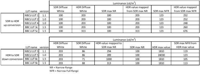
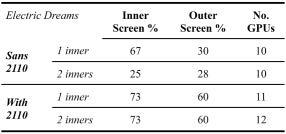
The characteristics of these conversions (Diffuse White values, Narrow Full Range limits) are different from one static 3D-LUT to another, as shown in Table 1.
Dynamic Conversions
Dynamic conversions are available and have the main advantages of:
• adapting to changes in lighting conditions or composition
• prioritizing shadows or highlights dynamically to better preserve detail.
One example of dynamic conversion technology is Advanced HDR by Technicolor®,10 a suite of HDR production, distribution, and display solutions that maximize image quality retention through HDR format conversions. The suite comprises two core tools, usable individually or in combination, to support a broad range of use cases, both file-based and real-time.
The first, Technicolor HDR Intelligent Tone Management (herein “ITM”), is used in production workflows to up-convert SDR camera signals or existing SDR content (e.g., archival footage, contribution feeds, commercials) to a production’s preferred HDR format (e.g., HLG or PQ per ITU-R BT.21005 ).
The second, Technicolor SL-HDR (herein “SL-HDR”), is used for content distribution, thus spanning the professional and consumer domains. On the professional side, HDR content is analyzed, down-converted if needed, and supplied with standardized metadata11-13 to parametrically describe such down-conversion to accompany the video signal so that, on the consumer side, the metadata can be applied, if and as needed, to reconstruct the original signal and adapt the content to the receiving display. SL-HDR enables the distribution of a single version of the content in either SDR or HDR.
ITM and SL-HDR are distinct, independent tools that make decisions dynamically. The goal is to preserve artistic
intent in the converted content. These tools can also be coupled to make conversions reversible, allowing for a perceptually lossless SDR-HDR-SDR round trip.1
This technology is referred to below as the “tested dynamic solution” and is a practical, working implementation.
Dynamic conversions generally use dynamic Diffuse White levels, which differ from the fixed levels used with static 3D-LUTs. Likewise, dynamic conversions typically manage NFR levels, which differ from those used in static 3D-LUTs.
Interoperability Issues
Given that static 3D-LUTs have characteristics that differ from one to another and further from dynamic conversion techniques, it is a problem that there is no signaling mechanism to identify attributes of HDR content (Diffuse White levels, NFR levels). Thus, there is no mechanism to reliably or automatically select an appropriate HDR-to-SDR down-conversion, static or dynamic.
As an example, let us consider an SDR playback source, as shown in Fig. 1 of Ref. 8, that is up-converted (at ‘B’) to an HDR HLG content using NBCU LUT 1 that performs an SDR-to-HLG conversion. This HDR content then needs to be down-converted back to SDR for delivery. As shown in Fig. 18 at ‘F,’ the down-conversion should use NBCU LUT 3, which performs an HLG-to-SDR conversion, to generate the SDR program output. In case of a wrong manual configuration of the system at the “HDR-to-SDR down-conversion” side, selecting, for instance, BBC LUT 8c instead of NBCU LUT 3, the generated SDR from BBC LUT 8c would differ drastically from the expected SDR NBCU LUT 3, as (from Table 1):
• 203 cd/m2 HDR Diffuse White level is mapped to 71 cd/ m2 SDR Diffuse White level with BBC LUT 8c and 86 cd/ m2 with NBCU LUT 3.
• 100 cd/m2 SDR maximum Narrow Range level is mapped from 1000 cd/m2 HDR level with BBC LUT 8c and 294 cd/ m2 with NBCU LUT 3.
• 1810 cd/m2 HDR maximum level is mapped to 105 cd/ m2 SDR maximum Narrow Full Range level with BBC LUT 8c and to 119 cd/m2 with NBCU LUT 3.
When there is no coupling between an SDR-to-HDR
TABLE 1. Diffuse White values and super-white usage of different 3D-LUTs.
up-conversion and a later HDR-to-SDR down-conversion, producing a perceptually identical SDR-HDR-SDR roundtrip, per1 is challenging for both static and dynamic conversions, being prone to misconfiguration in the field and limiting of system interoperability. For example, without such coupling, a dynamic HDR-to-SDR converter may opt for a conservative configuration, leading to sub-optimal SDR content.
Graphics Management
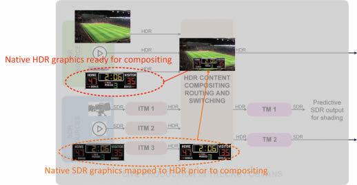
Live sports productions extensively use graphic insertions to present scores and analytics. As shown in Fig. 2, these graphic insertions can be realized:
• At the HDR level, HDR graphics are superimposed on the HDR content.
• At the SDR level, SDR graphics are superposed on the source SDR before up-conversion to HDR. Either way, to generate a consistent composition for the HDR content, the insertion must consider the reference lev-
els of the HDR content. More precisely, the final HDR Diffuse White level of the graphic must be the same as the HDR Diffuse White level of the HDR content.
Conversely, when down-converting an HDR composition to SDR, the graphics level must remain stable throughout the video.
Static 3D-LUTs inherently follow these rules for relying on fixed reference levels and, therefore, fixed Diffuse White levels.
However, graphics stability can be an issue for dynamic solutions that only rely on dynamic Diffuse White levels, as this can result in varying graphics levels, especially across scene changes.
HDR-SDR Conversion Characterization (HSCC) to Aid Interoperability
Six metadata Sufficiently Characterize HDR-SDR Conversions
We propose six metadata elements, each described in Table 2,
FIGURE 2. Graphics insertion in an HDR/SDR single-master workflow.
FIGURE 3. Typical single-master HDR/SDR workflow augmented with HSCC metadata.
Parameters Description
HDR Diffuse White “HDR_DW”
SDR Diffuse White “SDR_DW”
HDR Narrow Range “HDR_NR”
HDR Narrow Full Range “HDR_NFR”
SDR Narrow Full Range max “SDR_NFR_MAX”
Narrow Full Range min “NFR_MIN”
HDR Diffuse White level of the HDR content. Mapped to/from SDR Diffuse White level during conversion.
SDR Diffuse White level of the SDR content. Mapped to/from HDR Diffuse White level during conversion.
HDR luminance level of the HDR content, mapped to/from the Narrow Range maximum level of the SDR content during conversion.
HDR maximum luminance level of the HDR content, mapped to/from the “SDR_NFR_ MAX” level (defined below) of the SDR content during conversion.
Highest allowed code value used in the upper part of the SDR Narrow Full Range, mapped to/from the “HDR_NFR” level of the HDR content during conversion.
Lowest allowed code value used in the lower part of the Narrow Full Range. This value is common for the HDR content and the SDR content, i.e. in a conversion case, the HDR “NFR_MIN” value is mapped to/from the same SDR “NFR_MIN” value.
to support HDR-SDR conversion characterization (HSCC):
“HDR_DW,” “SDR_DW,” “HDR_NR,” and “HDR_NFR” can be expressed in cd/m2 or any coding representation that relates to cd/m2 values.
“SDR_NFR_MAX” and “NFR_MIN” can be expressed as 8b / 10b / 12b code values or percentages.
If the current HDR content is native from an HDR source (camera, post-production, …) and HSCC metadata is not present, then the HDR-to-SDR down-converter is free to select the values for the HSCC metadata.
The HSCC metadata are carried along with any HDR content, as shown in the typical single-master HDR/SDR workflow in Fig. 3.
The HSCC metadata could be carried in standardized containers, such as an extension of the SMPTE ST 2108-1 standard.14
Illustration of HSCC Metadata on HDR–SDR Conversion Curves
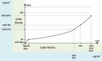
The use of HSCC metadata for an SDR-to-HDR up-conversion is shown in Fig. 4.
In an SDR-to-HDR up-conversion:
• NFR_MIN level of input SDR is mapped to the same NFR_ MIN level of output HDR.
• Narrow Range min level (64 in 10b codeword) of input SDR is mapped to the same Narrow Range min level of output HDR.
• SDR_DW level of input SDR is mapped to the HDR_DW level of output HDR.
• Maximum Narrow Range level (940 in 10b codeword) of input SDR is mapped to the HDR_NR level of output HDR.
• SDR_NFR_MAX level of input SDR is mapped to the HDR_NFR level of output HDR.
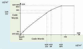
Use of HSCC metadata for an HDR-to-SDR down-conversion is illustrated in Fig. 5.
For an HDR-to-SDR down-conversion:
• NFR_MIN level of input HDR is mapped to the same NFR_MIN level of output SDR.
• Narrow Range min level (64 in 10b codeword) of input HDR is mapped to the same Narrow Range min level of output SDR.
• HDR_DW level of input HDR is mapped to the SDR_DW level of output SDR.
• HDR_NR level of input HDR is mapped to the Maximum Narrow Range level (940 in 10b codeword) of output SDR.
• HDR_NFR level of input HDR is mapped to the SDR_ NFR_MAX level of output SDR.
Mapping of HSCC Metadata on Existing 3D-LUTs
Any static 3D-LUT for HDR-SDR conversion can be characterized with HSCC metadata. The mapping of HSCC metadata on some popular static 3D-LUTs is given in Table 3.
A clear advantage for HDR content to carry HSCC meta-
FIGURE 4. Use of HSCC metadata in an SDR-to-HDR up-conversion. FIGURE 5. Use of HSCC metadata in an HDR-to-SDR down-conversion.
TABLE 3. Characterization of Some Existing Static 3D-LUTs with HSCC Metadata.
data is that as inventories of static LUTs mature, archival content remains able to efficiently describe its nature and a suitable, current LUT can be selected to have the appropriate characteristics.
Mapping of HSCC Metadata on Dynamic Solutions
By nature, dynamic solutions adapt to content and are generally configurable. A dynamic solution responding to HSCC metadata would build a conversion curve to conform with the metadata, as seen in the examples of Figs. 4 & 5, where the curves pass through the five characteristic anchor points defined by HSCC metadata. The dynamic solution can, therefore, be used as a static 3D-LUT replacement when HSCC metadata characterizes a specific static 3D-LUT.
The tested dynamic solution is optionally responsive to HSCC metadata. When enabled, the dynamic characteristics of the ITM and SL-HDR tools apply only to signal levels up to the static diffuse white levels of the content (both “HDR_DW” HDR Diffuse White level and “SDR_DW” SDR Diffuse White level), and all the signal levels above the static diffuse white levels and relative to sub-blacks and super-whites, namely “NFR_MIN”, “HDR_NR”, “HDR_NFR” and “SDR_NFR_MAX”, are managed differently, as sub-blacks and specular content.
Additionally, the tuning capabilities of the ITM and SL-HDR tools remain active, allowing the content creator to manage light, contrast, and saturation and ensure the consistent “look” that characterizes the production and its aesthetic.
The ability to accept and respond to Static Diffuse White from HSCC metadata additionally allows stable graphics management during conversions, as demonstrated in the next sections.
Advantages of HSCC Metadata
The proposed HSCC metadata, as a signaling mechanism, allows:
• Characteristics of a native HDR content to be reported, along with an optional specification for an expected SDR content, if conversion to SDR is needed. This allows an HDR-to-SDR down-converter to select the most appropriate HDR-to-SDR static 3D-LUT or the most appropri-
ate configuration of a dynamic HDR-to-SDR down-converter, to deliver an optimal SDR content.
• Characteristics of an HDR content produced by an SDR-to-HDR up-conversion to be reported, along with the specification of the source SDR. This allows an HDR-to-SDR converter to realize an optimal SDRHDR-SDR round trip by selecting the most appropriate HDR-to-SDR static 3D-LUT or the most appropriate configuration of a dynamic HDR-to-SDR down-converter.
• interoperability, including mixing of different equipment and technologies in a real workflow, thereby facilitating the transition from static to dynamic conversion throughout the industry.
Use of HSCC Metadata in Real Use Cases
Selection of the Correct Conversion When Receiving HSCC Metadata
Below we present four example use cases that benefit from using HSCC metadata.
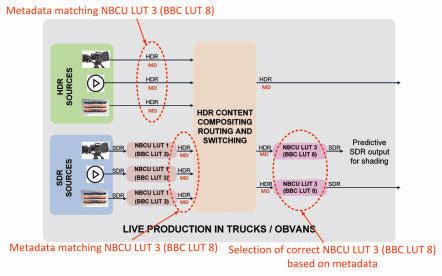
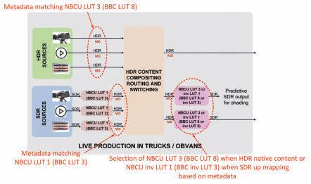
Static HDR-to-SDR 3D-LUT Selection to Mimic Current Workflows
A typical single-master HDR/SDR workflow is depicted in Fig. 1, compatible with both the NBCU8 and BBC recommendations.15
As an example, up-converters ITM 1/2/3 in Fig. 1 could be implemented using NBCU LUT 1 in an NBCU-compliant configuration (or BBC LUT 3 as an alternative BBC-compliant configuration) and down-converters TM 1/2 using NBCU LUT 3 (or BBC LUT 8). As shown in Fig. 6, up-converters ITM 1/2/3 further populate HSCC metadata with the values of the counterpart NBCU LUT 3 (BBC LUT 8). Thus, when ingesting the corresponding HDR video signal along with HSCC metadata, down-converters TM 1/2 can automatically select NBCU LUT 3 (BBC LUT 8), per the observed recommendation.
Here, native HDR content is distributed with HSCC metadata set to the values of NBCU LUT 3 (BBC LUT 8) because having HSCC metadata makes the selection of an appropriate HDR-to-SDR down-mapping LUT automatic and reliable.
Static HDR-to-SDR 3D-LUT selection with improved roundtrip
Both NBCU and BBC down-conversion LUTs are designed to preserve HDR highlights in the converted SDR, in accordance with Annex 10 of ITU-R BT.2408 report.2 A side effect of this design is a slight level reduction in the SDR Diffuse White to preserve compressed HDR highlights in the down-converted SDR. Examining the case of an SDR-HDR-SDR round trip, based on Table 1: i
• NBCU LUT 1 and BBC LUT 3 each map the 100 cd/m2 SDR Diffuse White level to 203 cd/m2 HDR Diffuse White level.
• NBCU LUT 3 maps the 203 cd/m2 HDR Diffuse White level to 86 cd/m2 SDR Diffuse White level (or 71 cd/m2 for BBC LUT 8).
As a result, the SDR Diffuse White level of the SDR source and the SDR returned from the SDR-HDR-SDR round trip will not match, representing an issue for content providers requiring that the resulting SDR match the source as closely as possible.1
Figure 7 illustrates how this can be improved when HSCC metadata are available.
Here, up-converters ITM 1/2/3 use NBCU LUT 1 (BBC LUT 3) and fill HSCC metadata with the values of NBCU LUT 1 (BBC LUT 3). Upon ingesting the corresponding HDR video signal and HSCC metadata, down-converters TM 1/2 can select a newly defined static 3D-LUT “inverse NBCU LUT 1” that is the inverse of the NBCU LUT 1 (or “inverse BBC LUT 3”), which needn’t preserve any compressed HDR highlights since the original is known to be SDR.
In parallel, native HDR sources are provided with HSCC metadata set to the values for NBCU LUT 3 (BBC LUT 8), to preserve the same behavior as the original recommendations for native HDR content.
Using HSCC metadata allows down-converters TM 1/2 to select the most appropriate LUT for each clip. This not only assures a perceptually perfect round trip for static 3D-LUT solutions but also makes the selection of the appropriate down-mapping LUT automatic and reliable.
FIGURE 6. Static HDR-to-SDR 3D-LUT selection to mimic current workflows.
FIGURE 7. Static HDR-to-SDR 3D-LUT selection with improved roundtrip.
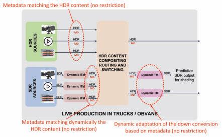
Dynamic HDR-to-SDR Down-Converter Configuration in a Fully Dynamic Workflow
The typical single-master HDR/SDR workflow depicted in Fig. 1 is also compatible with dynamic converters, as shown in Fig. 8.
In this example, down-converters TM 1/2 and up-converters ITM 1/2/3 comprise a dynamic technology responsive to HSCC metadata, of which the tested dynamic solution is a practical example.
When down-converters TM 1/2 receive native HDR content and HSCC metadata, the dynamic system configures itself to comply with the HSCC metadata, generating the proper down-conversion curve, as shown in Fig. 5, producing the desired SDR.
With an SDR source, up-converters ITM 1/2/3 generate HDR content with the appropriate dynamic Diffuse White, along with HSCC metadata that describes the characteristics of the up-conversion. At the down-converter TM 1/2 side, the dynamic system responds to HSCC metadata, generating the
down-conversion curve, the exact inverse of the up-conversion curve, producing the optimal SDR-HDR-SDR roundtrip.
Whenever the values of the HSCC parameters change dynamically, either from the native HDR content or from HDR content coming from up-conversion, the dynamic system adapts dynamically to the new characteristics.
The dynamic system can be configured with default values for the HSCC metadata so that, should the metadata become lost in the production system, the dynamic system still applies the default configuration, ensuring a consistent system behavior.
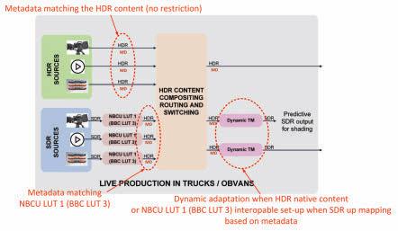
Mixing Static SDR-to-HDR 3D-LUT with Dynamic HDR-toSDR Down-Converter
The single-master HDR/SDR workflow (Fig. 1) is compatible with a mix of static and dynamic converters, as shown in Fig. 9.
This example mixed-conversion workflow uses static 3D LUTs for SDR-to-HDR up-converters ITM 1/2/3, such as NBCU LUT 1 (or BBC LUT 3), and a dynamic implementation for
FIGURE 8. Dynamic HDR-to-SDR down-converter configuration in a fully dynamic workflow.
FIGURE 9. Mixing static SDR-to-HDR 3D-LUTs with dynamic HDR-to-SDR down-conversions.
HDR-to-SDR down-converters TM 1/2, compatible with HSCC metadata. The tested dynamic solution is a practical example of this.
When down-converters TM 1/2 receive native HDR content and HSCC metadata, the dynamic system complies with HSCC metadata to generate the proper down-conversion curve, thereby producing the desired SDR.
When down-converters TM 1/2 receive HDR content from up-converters ITM 1/2/3 along with HSCC metadata describing the characteristics of the NBCU LUT 1 (BBC LUT 3), the dynamic system configures its conversion curve in accordance with the HSCC metadata characterizing NBCU LUT 1 (BBC LUT 3), thereby delivering an SDR that respects the characteristics of the source SDR.
The tuning capabilities of the dynamic solution enable the produced SDR to match the source closely. Alternatively, the produced SDR can be tuned to reflect a desired “look,” allowing flexibility in content creation. For such a use case, HSCC metadata provides strong guidance for the down-conversion, ensuring that the produced SDR falls within well-identified reference levels. This ensures a degree of interoperability and mixing of different equipment and technologies in a real workflow, facilitating the industry’s transition from static to dynamic conversion.
Sub-section
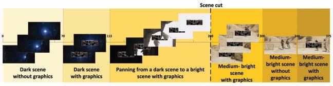
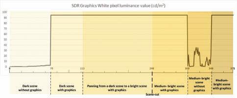
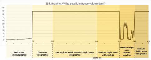
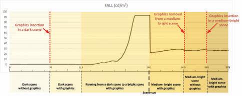
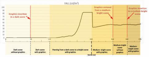
1 0 to 69 Dark scene without graphics
Management of Graphics with the Aid of HSCC Metadata
As we’d said above, any graphics to be inserted must match the HDR Diffuse White level. This ensures the graphics will remain stable in the down-converted SDR.
Dynamic solutions would normally determine reference levels dynamically and, as such, might not meet a graphics stability constraint through an HDR-to-SDR down-conversion. However, dynamic solutions responsive to HSCC metadata, such as the tested dynamic solution, do correctly manage graphics stability, as demonstrated in the following experiment.
Test Content
The experiment employs two source HDR contents:
• First, a native HDR content: an extract from the HDR version of the “ASC StEM2” i content.16 376 frames have been extracted, focusing on pertinent sections, as described below. The HDR content has been analyzed off-line and is characterized by an HDR diffuse white of approximately 400 cd/m2
• Second, an HDR content resulting from the up-conversion of an extract of the SDR version of the “ASC StEM2” content,16 herein named “SDR up-converted.” These 376 SDR frames correspond to those of the first content and were up-converted to HDR using the NBCU LUT 1, lead-
2 70 to 112 Same dark scene with graphics insertion at frame 70. Goals:
• Check if graphics insertion influences the down-conversion in a dark scene.
• Check that the graphics remain stable throughout the down-conversion on a dark scene.
3 113 to 239 Panning scene with graphics, from an almost black frame to an almost white frame (at HDR Diffuse White level). Goal is to check if inserted graphics remain stable throughout the down-conversion on a panning from dark to bright.
4 240 to 299 Scene cut between bright scene at frame 239 and medium-bright scene at frame 240, with graphics. Goals:
• Check if inserted graphics remain stable during a scene cut between a bright scene and a medium-bright scene.
• Check that the graphics remain stable throughout the down-conversion on a relatively static medium-bright scene.
5 300 to 339 Medium-bright scene, removing the graphics at frame 300. The goal is to check if graphics removal influences the down-conversion in a medium-bright scene
6 340 to 375 Medium-bright scene, inserting again the graphics at frame 340. The goal is to check if graphics insertion influences the down-conversion in a medium-bright scene
TABLE 4: Test Content sub-sections Description.
FIGURE 10. Composition of graphics on the HDR content.
ing to HDR content with an HDR diffuse white of 203 cd/ m2.
The 376 frames extracts are meant to represent common scene conditions that would point out potential issues when inserting graphics, as they include:
• Dark and bright scenes
• Panning from a dark scene to a bright scene
• Scene cut between bright scene and medium-bright scene
Graphics were inserted offline for each HDR content. An HDR diffuse white of 400 cd/m2 was used for graphics inserted into the native HDR content and 203 cd/m2 for the SDR up-converted content.
Figure 10 illustrates the composition. Each test content is made up of six sub-sections, listed in Table 4.
The inserted graphics is a 960 × 320 pixels rectangle with white at HDR Diffuse White level, as shown in Fig. 11.
The graphics dimensions are big enough to impact dynamic system image analysis.
The two specific dynamic system behaviors we see to analyze experimentally are:
1. Monitoring the value of a white pixel of the graphics in the down-converted SDR analyzes graphics stability throughout down-conversion.
2. Effect of the graphics insertion and removal on the SDR content, analyzed by computing the Frame Average Light Level (FALL) of the down-converted SDR on the whole frame, except for the area on which the graphics are inserted.
Graphics Management of a Dynamic System with HSCC Metadata
The dynamic system processes the native HDR content having an HDR diffuse white of approximately 400 cd/m2 with the following configuration.
• NFR_MIN = 4 (codeword)
• HDR_DW = 400 (cd/m2)
• SDR_DW = 95 (cd/m2)
• HDR_NR = 1000 (cd/m2)
• HDR_NFR = 1811 (cd/m2)
• SDR_NFR_MAX = 1019 (codeword)
FIGURE 11. Graphics inserted in the HDR content.
FIGURE 12. Graphics stability when downconverting the HDR native content with HSCC metadata.
FIGURE 13. Graphics stability when down-converting the SDR up-converted content with HSCC metadata.
The dynamic system processes the SDR up-converted content having an HDR diffuse white of 203 cd/m2 with the following configuration.
• NFR_MIN = 4 (codeword)
• HDR_DW = 203 (cd/m2)
• SDR_DW = 90 (cd/m2)
• HDR_NR = 1000 (cd/m2)
• HDR_NFR = 1811 (cd/m2)
• SDR_NFR_MAX = 1019 (codeword)
The results of the graphics stability throughout the down-conversion are provided in Figs. 12 & 13.
The results clearly show that the graphics on the down-converted SDR content is stable and fixed to the level set by the SDR_DW parameter, i.e., 95 cd/m2 for the native HDR content and 90 cd/m2 for the SDR up-converted content. This is confirmed:
• throughout a dark scene
• throughout a panning from dark to bright
• throughout a scene cut between a bright scene and a medium-bright scene
• throughout a medium-bright scene
The use of HSCC metadata forces the stabilization of the graphics in the down-converted SDR content and allows setting the SDR Diffuse White to a desired level.
The effect of the graphics insertion and removal on the
SDR content are provided in Figs. 14 & 15.
The results clearly show that:
• When inserting graphics in a dark scene (frame 70), there is no influence on the FALL of the underlying SDR content. This is true for both cases.
• When graphics are removed from a medium-bright scene (frame 300), there is a very limited (HDR native) or no influence (SDR up-converted) on the overall FALL of the underlying SDR content.
• When inserting graphics in a medium-bright scene (frame 340), there is no influence on the FALL of the underlying SDR content. This is true for both cases.
The use of HSCC metadata minimizes the influence of graphics insertion and removal on the underlying SDR content.
Further testing with other graphics characteristics (transparency, color gradient…) is envisioned.
Conclusion
As HDR production is becoming mainstream for live sports, this paper introduces to the industry a new metadata set, HCCS metadata, to support single-master production of live events and characterize SDR-to-HDR and HDR-to-SDR conversions that must be performed at different points and often by different stakeholders in the production and distribution workflow. This new metadata aids the selection
FIGURE 14. Effect of the graphics insertion and removal on the SDR content when down-converting the HDR native content with HSCC metadata.
FIGURE 15. Effect of the graphics insertion and removal on the SDR content when down-converting an SDR up-converted content with the six metadata.
of the appropriate conversions, whether static or dynamic, thereby improving interoperability, reliability, and automatic, real-time configuration of converters within production systems.
This paper further shows how dynamic conversion solutions react to HSCC metadata information and can allow full flexibility of HDR production while ensuring perfect SDR down-conversion.
We have demonstrated and tested a technique for graphics management, recognized as a major issue in live sports production by showing a dynamic solution driven by HSCC metadata information that ensures the proper behavior of graphics being inserted and the image upon which they are inserted throughout the conversion process.
Most importantly, the paper demonstrates that interoperability with existing solutions is fully supported and allows the industry to transition smoothly from static to dynamic conversion solutions, thereby expediting the creation and delivery of premium HDR and SDR content to consumers.
Further work will include standardization of HSCC metadata and recommended practices for its use.
Acknowledgments
The authors would like to thank our partners, particularly these individuals, who have contributed invaluably to this paper: Cobalt Digital: Ryan Wallenberg; Philips: Frank Kamperman, Rocco Goris.
References
1. D. Touze et al., “HDR Production—Tone Mapping Techniques and Roundtrip Conversion Performance for Mastering with SDR and HDR Sources,” SMPTE Mot. Imag. J., 132 6): 31-44, Jul. 2023, doi: 10.5594/JMI.2023.3277092.
2. International Telecommunication Union—Radiocommunication (ITU-R), Report BT.2408-7, “Guidance for operational practices in HDR television production,” Sep. 2023. [Online]. Available: https://www.itu.int/dms_pub/itu-r/opb/rep/R-REPBT.2408-7-2023-PDF-E.pdf
3. Redmann B., Touze D., Plissonneau F., Stein A., Ducos G., “HDR Challenges and Solutions,” 2022 NAB Broadcast Engineering and Information Technology (BEIT) Conference, Apr. 2022.
4. International Telecommunication Union – Radiocommunication (ITU-R), Recommendation BT.709-6, “Parameter values for the HDTV standards for production and international programme exchange,” March 2015. [Online]. Available: https:// www.itu.int/dms_pubrec/itu-r/rec/bt/R-REC-BT.709-6-201506-I!!PDF-E.pdf
5. International Telecommunications Union – Radiocommunication (ITU-R), Recommendation BT.2100-2, “Image parameter values for high dynamic range television for use in production and international programme exchange,” July 2018. [Online]. Available: https://www.itu.int/dms_pubrec/itu-r/rec/bt/R-REC-BT.2100-2-201807I!!PDF-E.pdf
6. EBU Recommendation R 103, version 3.0, May 2020, “Video signal tolerance in digital video systems.” [Online]. Available: https://tech.ebu.ch/docs/r/r103.pdf
7. “Release Notes for HLG Format Conversion LUTs v1.7”, BBC Research, Mar. 2024. [Online]. Available: https://downloads.bbc.co.uk/rd/pubs/papers/HDR/BBC_ HDRTV_HLG_LUT_Release_Notes_v1-7.pdf
8. “NBCUniversal Single-Master Broadcast Production and Distribution Recommendations #NBCU-Rec-UHD-HDR-01.19”, Version 1.19, Apr. 11, 2024. [Online]. Available: https://github.com/digitaltvguy/NBCUniversal-UHD-HDR-SDR-Single-Master-Production-Workflow-Recommendation-LUTs
9. Live from the FIFA World Cup, Sports Video Group, December 7th, 2022. [Online]. Available: https://www.sportsvideo.org/2022/12/07/live-from-the-fifa-world-cuphbs-ceo-dan-miodownik-cto-christian-gobbel-reflect-on-efforts-to-date/
10. Advanced HDR by Technicolor. [Online]. Available: https://advancedhdrbytechnicolor.com/
11. European Telecommunications Standards Institute (ETSI) TS 103 433-1 V1.4.1, Aug. 23, 2021, “High-Performance Single Layer High Dynamic Range (HDR) System for use in Consumer Electronics devices; Part 1: Directly Standard Dynamic Range (SDR) Compatible HDR System (SL-HDR1).” [Online]. Available: https://www.etsi. org/deliver/etsi_ts/103400_103499/10343301/01.04.01_60/ts_10343301v010401p. pdf
12. European Telecommunications Standards Institute (ETSI) TS 103 433-2 V1.3.1, Aug.
23, 2021, “High-Performance Single Layer High Dynamic Range (HDR) System for use in Consumer Electronics devices; Part 2: Enhancements for Perceptual Quantization (PQ) transfer function based High Dynamic Range (HDR) Systems (SL-HDR2).” [Online]. Available: https://www.etsi.org/deliver/etsi_ts/103400_1034 99/10343302/01.03.01_60/ts_10343302v010301p.pdf
13. European Telecommunications Standards Institute (ETSI) TS 103 433-3 V1.2.1, Aug. 23, 2021, “High-Performance Single Layer High Dynamic Range (HDR) System for use in Consumer Electronics devices; Part 3: Enhancements for Hybrid Log Gamma (HLG) transfer function based High Dynamic Range (HDR) Systems (SLHDR3).” [Online]. Available: https://www.etsi.org/deliver/etsi_ts/103400_103499/1 0343303/01.02.01_60/ts_10343303v010201p.pdf
14. SMPTE, ST 2108-1, Sep. 12, 2018, “HDR/WCG Metadata Packing and Signaling in the Vertical Ancillary Data Space.” [Online]. Available: https://ieeexplore.ieee.org/ document/8471270
15. “Guidance on Format Conversion in HLG Production,” BBC Research, Apr. 2020. [Online]. Available: http://downloads.bbc.co.uk/rd/pubs/papers/HDR/BBC_ HDRTV_HLG_LUT_Production_Guide.pdf
16. American Society for Cinematographers (ASC) Standard Evaluation Material II (StEM2), “The Mission,” 2022. Used with permission. [Online]. Available: https:// theasc.com/asc/stem2
About the Authors
David Touze is a system architect at InterDigital, focusing on high dynamic range (HDR) HDR and wide color gamut (WCG) techniques adapted to live video production and distribution workflows.
Bill Redmann is InterDigital’s director of standards. He contributes to SMPTE, the Advanced Television Systems Committee, and the Ultra HD Forum and chairs each group’s sustainability group. He holds 92 U.S. patents, an MS in engineering from the University of California, Los Angeles. and is an SMPTE Fellow.
Frederic Plissonneau is a system architect at InterDigital. With a background in ASIC design and video compression, he is currently focused on HDR technology.
Patrick Morvan is a senior research engineer at InterDigital. He has expertise in color science and broadcast applications. He is currently focused on color management for high-dynamic-range workflows.
Robin Le Naour is a senior engineer at InterDigital. With a background in real-time software development, system architecture, and image/video processing, he is currently developing HDR real-time applications.
Laurent Cauvin, senior engineer at InterDigital, has been working on video processing since 1985. He is currently involved in HDR, mainly in Inverse Tone Mapping (algorithms, system architecture, hardware, and software porting).
Valérie Allié is a senior director leading InterDigital’s Video Solutions Research Group. This group supports the deployment of 2D and immersive video codecs, with a particular focus on HDR technologies.
KEYWORDS ULTRA-LOW LATENCY // OTT STREAMING // METAVERSE // GAMING // BETTING // QUALITY OF EXPERIENCE (QOE) TUTORIAL
Ultra-Low Latency OTT Delivery: The Killer Technology for Betting, Social Networking and Metaverse
By Mickaël Raulet and Khaled Jerbi
Abstract
Ultra-low latency over-the-top (OTT) video streaming is becoming increasingly important in gaming, metaverse, and gambling applications, enabling social interaction and monetization in live events such as sports and concerts. Moreover, all those applications are conceptually converging. These applications require real-time, interactive experiences that are highly responsive and immersive, and ultra-low latency OTT streaming is essential for delivering this type of experience. Tremendous innovation resources have been invested to build robust OTT delivery systems with ultra-low latency capabilities. Necessary optimizations affect most steps, from encoding to packaging and even last-mile delivery. This paper explains a setup leveraging ultra-low latency technology using the Live Media Ingest Protocol and Just-In-Time packaging. We also explore how such a setup can be used to enable remarkable technologies that directly impact the Content Delivery Network (CDN) performance and the users’ quality of experience (QoE) to achieve the seamless and immersive experience they require.
Over-the-top streaming has revolutionized how we consume media, enabling us to watch video content on demand without the need for traditional cable or satellite TV subscriptions. With the rise of gaming, metaverse, and betting applications, the industry requirement to go further and seek ultra-low latency OTT streaming has become increasingly apparent. Ultra-low latency streaming refers to the ability to deliver content with extremely low delay between the source and the end-user, generally required to be under 2 sec. In the context of gaming, metaverse,1 and betting applications, embedding ultra-low latency video is crucial to ensure a seamless and immersive experience. Users require near real-time interaction with other users, and any lag or delay can significantly impact their mutual experience.
In gaming, we already know that ultra-low latency streaming is critical for competitive online gameplay. An innovative way to improve gamers’ experience would be to mix the game with another event broadcast via OTT, such as an advertisement, live concert, or sports event. The gamer should be able to interact with both events and even with other users simultaneously. The latency requirement on the newly added event must be under 1 sec. Similarly, in the metaverse, users require real-time interaction with other users and virtual objects to fully immerse themselves in the virtual world. Any lag or delay can break the illusion of being in the virtual environment. Low latency streaming is essential in betting applications to ensure fair and transparent results. Any delay in the streaming of the event can lead to suspicions of cheating or fraud, which can damage the reputation of the application and deter users from using it in the future. This paper explores the challenges in delivering low-latency video streaming in a gaming and a virtual environment, the
Ultra-low latency OTT streaming is essential for delivering real-time, interactive experiences in gaming, metaverse, and betting applications. By reducing latency to less than 2 sec, we have dug deep to master this technology, opening a new world of opportunities for seamless user engagement and innovative applications that demand high responsiveness and immersion.
more cost-effective than traditional satellite or cable delivery. While satellite and cable providers often require users to sign long-term contracts, pay for expensive hardware installations, and pay for bundles of channels that may include channels they’re not interested in, OTT services typically offer more flexible pricing options for exactly what the user needs to watch.
benefits of achieving ultra-low latency, and the emerging technologies that can help improve the quality of experience.
OTT Latency Evolution in a Nutshell
OTT delivery has several advantages over traditional satellite or cable delivery of video content. First, it can provide better video quality than traditional satellite or cable. OTT services can deliver high-quality video content in resolutions up to 4K, and they can use adaptive streaming technologies to ensure that users receive the best possible video quality based on their internet connection. Additionally, OTT delivery is more flexible than satellite or cable. With OTT, users can access content on various devices, including laptops, smartphones, tablets, and smart TVs, and they can watch that content anywhere with an internet connection.
In contrast, satellites and cables are tied to a physical infrastructure and are limited by the availability of cables and satellite signals. We can also add that OTT delivery is often
That said, one of the biggest challenges that video streaming services face is latency. Latency refers to the delay between when a video is captured and when it is played back, and it can be a significant problem for live events like sports or news broadcasts. At the beginning of OTT delivery, the overall latency was around 50 sec. Imagine the frustration of hearing your neighbors cheering for a goal that you get to watch 50 sec later. Considering the video flow, the most important latency factor is the segment duration. That duration also impacts the latency at each delivery step: encoding, packaging, storing, delivering, buffering, and displaying. As shown in Fig. 1, an analogy of stream delivery steps is like a fluid that progresses from one container to another. Configurations A and B illustrate how waiting for large containers (large segments) to be filled takes much more time to fill and produce an output than smaller ones.
Even though it is possible to adopt configuration B and reduce the segment duration to minimal values, such as 0.5 sec, to get an impressive latency, this manipulation would have a disastrous impact on video quality because it involves putting several data-consuming keyframes at the segment’s borders. Thus, smarter solutions need to be found. In recent years, adopting the Common Media Application Format (CMAF)2 and Content Delivery Network (CDN) optimization has helped solve this issue. CMAF allows for video segments to be delivered in smaller parts called chunks, which improves the efficiency of CDNs in delivering content to end-users while keeping reasonable encoding configurations.
The CMAF chunking is illustrated in configuration C of Fig. 1 and enables reducing the bandwidth pipe while keeping reasonable segment durations. CDN optimization, on the other hand, involves strategically placing servers around the world to reduce the distance between the server and the end-user, thereby reducing propagation latency. The combination of these two technologies has led to a significant reduction in latency for OTT video streaming to values around 5 sec, improving the viewing experience for millions of users around the world.
There is still a need to reduce latency further as new requirements and applications push the limits toward a latency requirement of less than 2 sec. Indeed, in addition to gambling and gaming, which today have millions of followers, the emergent metaverse technology may be the next significant social experience for all generations, following on the heels of social networks that have dominated the previous decade. These new applications require ultra-low latency to produce an engaging and realistic user experience. Figure 2 summarizes the applications for each latency interval according to video segmentation technology. Notice the number of new emergent applications in the range of ultra-low latency.
FIGURE 1. Video delivery pipeline with fluid analogy: (a) large segments (B) small segments (c) large segments with CMAF chunks.
Ultra-Low Latency in Practice
Reducing latency in OTT video streaming is an ongoing challenge for streaming providers. One strategy is to combine efficient encoding configuration tuning with packager ingest improvement using the Media Ingest Protocol and, optionally, CDN caching optimization using byte range technology.3,4 Optimizations can also be added at the player and mobile network levels.5 We explore all these aspects in this section.
To begin with, tuning the encoding configuration can help reduce latency by optimizing the video encoding process. Specifically, video encoding settings such as bitrate, resolution, and frame rate can be adjusted to balance video quality and latency. For instance, reducing the resolution and frame rate can lower latency without significantly impacting video quality. Moreover, compression standards offer the possibility to parallelize the compression of frame parts such as slices and tiles. This parallelization is crucial for high resolutions. In addition, encoding techniques such as GOP (Group of Pictures) alignment, lookahead, frames reordering, and video buffering can significantly help reduce the time it takes to encode the video content. We tested our encoder with 1080 × 1920 video at 25 frames per second (fps) with different presets. In Fig. 3, we can see that latency is reduced by a factor of three between the best quality preset and the ultra-low latency. The lookahead parameter is critical in encoding because it brings valuable predictive information from future frames to encode current ones better. However, using future frames can tremendously impact the latency, as shown by the difference between the high-quality and best-quality presets (yellow line). Note also that the curves are not linear and that dramatic changes in B frames or reordering numbers are unnecessary for a significant latency reduction.
A related aspect of this setup is the video quality (VQ). In the previous section, we found that tuning encoder parameters can reduce the encoder latency. However, those parameters can also impact VQ, and we measure the relative impact using the bitrate ratio necessary to maintain the same VQ as the original bitrate. Figure 4 shows some results of varying
the bitrate. The latency decreases as expected as the relative bitrate increases, though curves are also not linear. For example, moving from 3.5 to 2 sec—about a 45% latency improvement—requires only a 10% bitrate increase. But, moving from 1.5 to 1.2-sec latency—about a 20% improvement—requires about a 65% bitrate increase. Characterizing this nonlinear behavior is important because we have identified an interval where we can dramatically reduce latency with a very low cost of increased bitrate.
It is important to mention that Fig. 4 shows an encoder-only latency based on the HD video encoding testbench. The overall OTT latency will include the other steps in Fig. 5.
Going beyond the encoder, the next step is the OTT packaging. In this step, we encapsulate the bitstream into an ISOBMFF format6 with the required playlists. Traditionally, this step was achieved with MPEG-2-TS format. So, the encoder multiplexes the MPEG-2-TS, and then packagers have to demultiplex it and repackage it into ISO-BMFF format. That process is another source of latency. Recently, the DASH-IF and CMAF-IF developed a new protocol called Live Media Ingest Protocol7 that allows sending CMAF format directly from the encoder to the packager (more generally, from any sender to receiver entity) and thus removing the MPEG-2-TS manipulations from the flow.
Improving the packager ingest with this protocol is another strategy we deployed to reduce OTT video latency. The protocol defines two interfaces. One is for sending already packaged DASH format segments, and the other is for sending non-packaged CMAF fragments and chunks. The latter interface suits our setup because we use a smart Just-In-Time packager as a receiving entity. Figure 5 shows the pipeline of the improved video flow. We measured around 1.5 sec latency gain compared to MPEG-2-TS usage.
On the network side, optimizing the CDN cache with byterange technology is also crucial to reducing OTT video latency. Byterange technology improves the efficiency of the CDN cache and thus improves CDN latency. The technology is basically about delivering video chunks or parts without having them physically in the origin or CDN. OTT video players can be configured for either low latency or classic
FIGURE 2. Evolution of application using OTT streaming regarding latency and its corresponding technology of video segmentation.
latency. In the case of classic latency, the CDN should be able to deliver normal segments, and in the case of low latency, the player will ask for chunks, and the CDN should be able to deliver them.
Consequently, both segments and their corresponding chunks will be present in the CDN cache at the same time. Byterange technology allows requesting parts of the segment using their start position and size, so the CDN does not require more to store chunks. Here is an example of an HLS byterange request syntax of file part 6 starting at position 2000 in the file with a size of 100 bytes: #EXT-X-PART:DURATION=0.2,URI=”part6.mp4”,BYTERANGE=100@2000
Another important network breakthrough is the rising 5G network and its capabilities of reducing latency while transferring video from origins or CDNs to the final user. We could benefit from such technology to build promising unicast/multicast/broadcast infrastructures.5
All of the technologies described combined allowed us to achieve an impressive 1.7 sec latency, and we know that
further improvement is possible using more buffering and network optimization.
Another important step that has a tremendous impact on latency is the player. In this experiment, we are using avplayer, the native iOS player. Players struggle to manage buffering, dealing with network fluctuations and switching. If a player buffers a lot, it will create useless latency. However, if it does not buffer enough, any minor network interruption would lead to video stuttering and forced buffering, directly impacting the QOE. Players also have another technique to manage networks and buffers using accelerated and slowed playback. More precisely, if a player has enough data in the buffer, it is possible to softly increase the playout speed by 10% or 20% and slowly get to the live edge, and that recovery adjustment is hard for normal viewers to distinguish.
Similarly, if the player notices a low buffer level, it can decelerate the playback and keep the edge while having more time to buffer new data. For switching, every time a
FIGURE 3. End-to-end latency evolution according to encoding parameters.
FIGURE 4. Required bitrate ratio to maintain video quality according to latency.
user changes a channel, the player must switch and wait for the first available segment key frame to be able to start decoding. In this context, technologies like HESP8 suggest innovative advanced techniques to make that switch fast and seamless, using a sidetrack with reference frames only, allowing the decoder to find keyframes at any time and quickly start rendering. Notice that a similar effort is being made at DASH-IF to develop fast-switching technology.
Conclusion
In this paper, we presented the concept of ultra-low latency OTT and explored the different technologies and applications that helped reduce it. Practically, we showed how to reach about 1.7-sec overall latency from the encoder to playout, using the encoder, packager, and network optimizations. Since our contribution can only cover part of the video delivery flow, we depend on other industrial infrastructures such as 5G networks, CDN, and players. In this context, we relied on excellent low-latency players with advanced technologies to handle ultra-low latency streams. We also partnered with CDN and 5G providers that furnished ultra-low latency adapted setups. Latency can be further reduced by leveraging emerging network technologies like HTTP/3. This advancement could enhance packager behavior by allowing it to begin packaging the next segment when a network promise is made rather than waiting for the actual request to be received. Optimizing the encoder’s performance by reducing the encoding buffer while maintaining a stable and controlled bitrate can also contribute to lower latency. Continuous improvements by CDN providers in traffic management can further support achieving these lower latency goals.
These current results show that we are using the killer technology of ultra-low latency, and it has been revealed to be key for new applications with strong latency constraints when using OTT. Among these applications, we bring OTT video to gambling, gaming, auctions, and the emergent metaverse technology. With ultra-low latency, we should also be able to create new interactions where the gaming universe can cross into another event brought on by OTT. Reducing the latency would be more consuming in bandwidth, but it is worth it. The metaverse is about to revolutionize the way we interact. It will be Social Network 2.0, where texts and images are exchanged and a fully immersive experience that requires video. We believe ultra-low latency streaming is one of the main keys to entering this universe.
References
1. Dwivedi et al., 2022 Y. Dwivedi, L. Hughes, A. Baabdullah, S. Ribeiro-Navarrete, M. Giannakis, M. Al-Debei, D. Dennehy, B. Metri, D. Buhalis, C. Cheung, K. Conboy, R. Doyle, D.P. Goyal, A. Gustafsson, I. Jebabli, Y.-G. Kim, J. Kim, S. Koos, D. Kreps, F. Wamba, “Metaverse beyond the hype: Multidisciplinary perspectives on emerging challenges, opportunities, and agenda for research, practice, and policy,” International Journal of Information Management, 66 (2022), Article 102542.
2. International Organization for Standardization /International Electrotechnical Commission (ISO/IEC) 23000-19:2018 Information technology, multimedia application format (MPEG-A) Part 19: Common media application format (CMAF) for segmented media.
3. Web Application Video Ecosystem—DASH-HLS Interoperability Specification (CTA5005), CTA-Wave.
4. W. Law, E. Toullec and M. Raulet, “Universal CMAF Container for Efficient Cross-Format Low-Latency Delivery,” SMPTE Mot. Imag. J., 131 ( 6): 17-25, Jul. 2022, doi: 10.5594/JMI.2022.3175955.
5. C. Burdinat, T. Stockhammer, M. Raulet and T. Biatek, “Network Operator-Provided 5G Streaming Media and Future Broadcast Services,” SMPTE Mot. Imag. J., 131 (6):10-16, Jul. 2022, doi: 8.10.5594/JMI.2022.3175990
6. International Organization for Standardization (ISO/IEC) 14496-12:2015—Information technology—Coding of audio-visual objects—Part 12: ISO base media file format
7. “DASH-IF Live Media Ingest Protocol” Technical Specification. [Online]. Available: https://dashif-documents.azurewebsites.net/Ingest/master/DASH-IF-Ingest.html
8. Pieter-Jan Speelmans. “Low encoding overhead ultra-low latency streaming via HESP through sparse initialization streams,” Proc. of the 1st Mile-High Video Conference (MHV ‘22). Association for Computing Machinery, pp. 115-116, New York. NY. [Online]. Available: https://doi.org/10.1145/3510450.3517294
About the Authors
Khaled Jerbi is an advanced research engineer with more than 15 years of experience in video compression and delivery. Jerbi is part of Ateme’s innovation team, mainly working on discovering new technologies and implementing proofs of concept on exciting topics.
Mickaël Raulet is the CTO of Ateme, where he drives research and innovation with various collaborative R&D projects. He represents Ateme in several standardization bodies and is the author of numerous patents and more than 100 conference and scientific journal papers.
This paper first appeared in the Proceedings of the NAB 2023 Broadcast Engineering and Information Technology (BEIT) Conference. Reprinted here with permission of the author(s) and the National Association of Broadcasters, Washington, DC.
DOI: 10.5594/JMI.2024/KFLQ4529
Date of publication: 1 October 2024
FIGURE 5. Video flow optimized pipeline with Live Media Ingest Protocol interface 1 for CMAF ingest.
KEYWORDS LINEAR STREAMING // HTTP ADAPTIVE STREAMING (HAS) // DYNAMIC ADAPTIVE STREAMING OVER HTTP (DASH) // AV1 APPLICATIONS/PRACTICES
Using Single-Pass Look-Ahead in Modern Codecs for Optimized Transcoding Deployment
By Vibhoothi Vibhoothi, Julien Zouein, François Pitié, and Anil Kokaram
Abstract
Modern video encoders have evolved into sophisticated pieces of software in which various coding tools interact. In the past, single-pass encoding was not considered for video-on-demand (VOD) use cases. In this work, we evaluate production-ready encoders for H.264 (x264), HEVC (x265), AV1 (SVT-AV1) along with direct comparisons to the latest AV1 encoder inside NVIDIA GPUs (40 series), and AWS Mediaconvert’s AV1 implementation. Our experimental results demonstrate that single-pass encoding inside modern encoder implementations can give us excellent quality at a reasonable compute cost. The results are presented as three scenarios targeting high, medium, and low complexity accounting qualitybitrate-compute load. Finally, a set of recommendations is presented for end-users to help decide which encoder/preset combination might be more suited to their use case.
The ever-increasing demand for online video content has led to the emergence of technologies aimed at reducing transcoding costs in both on-premises and cloud-based environments.1 In a typical video workflow, which includes transcoding, metadata parsing, and streaming playback with HTTP adaptive streaming (HAS/AS), transcoding consumes a significant share of available resources. Given the increasing volume of video traffic, the resources consumed by video transcoding come under increasing scrutiny. HAS/AS was developed to standardize how different bitrate/quality versions of the same clip could reduce the overall bandwidth requirement for video traffic. However, transcoding remains a core part of creating those versions; therefore, the resource issue for transcoding persists. We, therefore, need encoding algorithms that balance the three core resources: bitrate, quality, and compute.
Currently, industrial lore holds that the highest quality/ lowest bitrate trade-off is only possible through multipass encoding.4 This incurs substantial computational costs and is not very suitable for live streaming. Because of the increasing complexity of modern codecs (AV1, HEVC, VVC) and the demand for encoders in live broadcast applications,5 more effort has been put into developing an optimal single-pass encoding scheme.6,7 these schemes involving “lookahead” have evolved significantly, leveraging metadata (e.g., motion information, rate-distortion trade-off, etc.) extracted from frames ahead to inform encoding decisions and the coding process.7,8 This results in lower computational costs compared to multipass encoding. It is now widely suspected that these single-pass schemes may be competitive, but no quantitative assessment has been conducted. In this paper, we make the following contributions.
Industrial lore holds that the highest quality/lowest bitrate trade-off is only possible through multipass encoding. This incurs substantial computational costs. Recently, more effort has been put into developing optimised singlepass encoding schemes. It is now widely suspected that these single-pass schemes may be competitive, but no quantitative assessment has been conducted.
1. Practical Dataset for Codec Comparison: We use new high-quality source material from the American Society of Cinematographers (ASC) StEM29 dataset (UHD1@24fps). Our clips (62) are longer (4-30 sec) than the short clips typically used in encoder development (2-4 sec), and together with this production-ready content, provide a more practical assessment of the encoders under test.
2. Practical Production-Ready Codecs: We focus on analyzing production-ready encoder implementations instead of a research codebase. We select representative codecs once we have evidence that they are used in production at scale; hence, SVT-AV1 is our reference for AV1 since Meta uses SVT-AV110 for Instagram Reels. In addition, we use x264 for the H.264 standard and x265 for the HEVC standard. We tested AV1 encoding in NVIDIA’s 40 Series GPU to evaluate the hardware encoding performance. Lastly, we tested the latest AV1 implementation inside AWS-MediaConvert to evaluate cloud performance. We evaluate single-pass and multipass settings at 12 target bitrates for 5-6 target presets. We use the VBR control method, which is typically used in production.
3. Practical Codec Evaluation: In evaluations like these,
given N clips tested with M codecs, each using 5 presets and 12 bitrates, the total number of data points, 62NM, becomes very large (> 35k in our case). To allow us to draw insights from this large amount of data, we analyze the data from the perspective of different target requirements. Our evaluation, therefore, focuses on the following aspects:
a. The ability of the encoder to retain and achieve the desired target bitrate within certain bitrate boundaries;
b. Capability to attain perceptually lossless quality; and
c. The encoding complexity for the dataset. Results are presented for three distinct scenarios, representing high, medium, and low-complexity use cases: i) High-Quality Agnostic-Complexity, ii) High-Quality Low-Complexity, and iii) Agnostic-Quality Low-Complexity settings.
We also briefly analyze the results using the Bit-Distortion Aggregation method (Smart BD-Rate)11 to provide a more practical representation of the dataset within each scenario. The analysis with Smart BD-Rate did not change our findings.
Our findings suggest that in high-complexity UHD-1 encoding scenarios, SVT-AV1 1-pass VBR encoding at preset 2 outperforms all other codecs. Specifically, it achieves approximately 72% bitrate savings compared to x264, 39% compared to x265, 50% compared to nvenc-av1, and 40% compared to AV1 in AWS MediaConvert, as measured by the BD-Rate of video multimedia assessment fusion (VMAF). For the medium-complexity UHD-1 encoding scenario, SVT-AV1 1-pass VBR encoding at preset 6 outperforms all the other codecs. The NVIDIA’s AV1 encoder (nvenc-av1) achieved 5% better bitrate savings than the “x265-Medium@2-pass” encoding settings. Lastly, when we evaluated the AWS Mediaconvert solution, it was very similar to x265-very slow 2-pass, at 1.8% BD-Rate loss but 25 times faster.
Technical Overview of Single-Pass Encoding System
The key challenge for a production-ready encoder is to hit a target bitrate or bitrate range for a piece of encoded video content while ensuring that the output picture quality is sufficiently high. Additionally, it must achieve this at some reasonable computational cost. This intuitive constraint leads to rate/distortion optimization (RDO) in which encoder parameters (e.g., quantizer step size, motion search range, block size) are optimized to achieve that balance.12 In prac-
tice, we must also distribute encoded bits evenly in some way over the content. This ensures that decoder buffers do not overflow. Intuitively, this implies a “bit budget” for encoding a certain number of frames. It is the “rate control” algorithm in a practical deployment of an encoder responsible for this clip-level behavior while attaining good picture quality. The key intuition behind a good rate controller is to assign bits from the bit budget proportionally to picture complexity in some way. Hence, for complex frames (for example), we may deploy more bits than in simpler frames and assign those bits from our fixed bit budget. But until we visit a frame and analyze the complexity at that time instant, we do not know how to assign a bit of budget for that frame.
Two main strategies exist multi-pass encoding, which encodes clips multiple times to refine bit allocation, and single-pass encoding, which uses statistical models or lookahead techniques to predict bit needs. Multi-pass encoding, by definition, will perform better at RDO than single-pass encoding but at significantly higher complexity because of the multiple encoder passes. Modern encoders now have evolved a range of “modes” that encapsulate both RDO and Rate Control, e.g., single-pass, multi-pass (2-pass or 3-pass), and constant bitrate (CBR), variable bitrate (VBR), and Constant Rate factor (CRF).
In the early days, during MPEG-2 development (1999), Mohsenian et al.13 showed that a single-pass encoding using MPEG-2 with buffer constraints could be useful for real-time applications for broadcast and digital applications using CBR and VBR rate-control mode. In 2005, Ma et al.14 proposed a technique that is a one-pass rate control at the frame level, with a partial two-pass rate control at the macroblock level, which improved the target bitrate accuracy. Around 2007, Chen et al.15 explored various rate-control algorithms and their application. Again, single-pass was recommended for live VOD use-case with VBR, and two-pass rate-control mode was used for storage use-cases.
Fast-forward to 2021, Hao et al.8 demonstrated that single-pass encoding of AV1 (SVT-AV1) is useful for VOD applications and can achieve similar or better performance than x264/5, VP9, notably the encoder achieves 10-20% better bitrate savings for the same compute complexity. It was noted that SVT-AV1 (preset 5) achieved more than 20% bitrate savings compared to VP9 (preset 1). Later, in 2021, Nguyen et al.16 showed that AV1 could outperform HEVC-HM by 11.51% for UHD and FHD test sequences.
Modern production-ready open-source encoders like the x26517 encoder achieve 40-50% efficiency over its predecessor, x264. The x265 supports multiple rate-control options like 1-pass, 2-pass, and multi-pass for CBR, VBR, CRF, and constant quality. In single-pass encoding, x265 uses a lookahead window to compute pre-encoding data such as distortion costs, bit information, average distortion metrics, block type percentages, and keyframe positions. This pre-encoding metadata is utilized in the final encoding phase to reduce redundant computations and save CPU cycles. The SVT-AV17 is a production-ready AV1 codec adopted by the Alliance of Open Media. They also use a lookahead window in single-pass encoding to compute frame metadata, including motion estimation distortion and variance of motion estimation costs. In multi-pass encoding, SVT-AV1 uses this information and a subset of coding tools to improve final video quality. The encoders also contain various parameters to find the correct balance between encoding bitrate, quality, and complexity. These are mediated through preset options. For example, SVT-AV1 has 13 presets (0 to 12), with approximately 35 distinct options fine-tuned across speed presets. For instance, different presets determine the maximum number of reference frames allowed. Presets 6 and all allow up to 7 reference frames, and this limit gradually declines to 4 frames in the fastest preset (preset 12). Certain presets/ options allow fine-tuning in specific transcoding use cases. For instance, enabling the Low-Delay configuration is appro-
FIGURE 1: Screenshots of the StEM2 Dataset. The Dataset contains cinematography content at UHD-1@24fps.
FIGURE 2: Dataset distribution with respect to spatial energy (e, x-axis) and temporal energy (h, y-axis). Clips at the top right have high content complexity, and those at the bottom right have low content complexity. Most production-ready clips are in the mid-band area.
priate for screen content coding in video conference applications, which could yield a substantial 35% improvement in bitrate savings.18
Experimental
Setup
To study the behavior of the encoders, we have selected a cinematic sequence (see Datasets section below). For encoding comparison, we chose three software, one hardware encoder, and one cloud-based encoding system (see Encoder Configuration Section). For computing the objective metrics, we are using the VMAF Library19 (8b3b975c) using Compute Unified Device Architecture (CUDA) GPU acceleration to compute metrics in real-time (30-40 fps vs 1-2 fps).
Dataset
We use 62 shots (out of 158) from the StEM2 Dataset from the American Society of Cinematographers.9 The original sequence is 17:30 mins long with a UHD-1 (3840 × 2160p) resolution at 24 fps (SDR 10 bits). Each shot has a minimum
duration of 4 sec, with an average duration of 9 sec. The overall duration of the dataset is 08:37 mins. Figure 1 shows a screenshot of the dataset, and Fig. 2 represents the spatial energy (SE) and temporal energy (TE) of the video computed using the open-source video complexity analyzer (VCA).20 SE and TE serve as indicators of video complexity; the SE is calculated via a low-pass Discrete Cosine Transform (DCT) across the video, providing a per-frame value, while the maximal temporal variance between consecutive frames determines the TE. Higher TE values signify increased motion within the video, whereas elevated SE values denote spatially intricate structures, contributing to increased encoding complexity.
Encoder Configuration
The encoders to be tested are listed in Table 1. Sample command lines are listed in Appendix A1 for all five codecs in the VBR modes. A set of 12 target bitrates is selected for the codecs, {0.5, 1, 2, 3, 4, 6, 8, 10, 12, 14, 16, 20} Mbits/s. For each target bitrate, we have set the Keyframe interval to 131, the maximum output bitrate to be 120% of the target bitrate, and the buffer size to be twice the target bitrate. For example, if the target bitrate is 8M, the max rate is set to be 9.6M, and the buffer size is 16M. We have computed more than 35k encodes (35,268) for analysis. For a particular preset, say x264, which is very slow, we have 12 target bitrates *62 videos, resulting in 744 encodes. We are computing and analyzing around 5,000 data points for a given video.
Text in red should be changed appropriately based on x264/ x265.
TABLE 1. The Encoders Analyzed in this Work. Each Row Also Shows the High-level Configurations Tested. Each Encoder/preset is Evaluated at 12 Different Target Bitrates to Create Rate-Distortion (RD) Curves.
# Encoder Rate Control Options and Passes Presets Tested
1 X264, Core 164 (LAVC 60.3.100)
2 X265, 3.5+102-34532bda1
3 SVT-AV1, v1.8.0
4 NVENC-AV1 Cuda 12.1 (LAVC 60.3.100)
Encodes
Variable Bitrate (VBR) in 1-pass and 2-pass veryslow, slow, medium, fast, veryfast, ultrafast (6) 4464x2; 8928
Variable Bitrate (VBR) in 1-pass and 2-pass veryslow, slow, medium, fast, veryfast, ultrafast (6)
4464x2; 8928
Variable Bitrate (VBR) in 1-pass and 2-pass 2, 4, 6, 8, 10, 12; (6) 4464x2; 8928
Variable Bitrate (VBR) in 1-pass and 2-pass P1, P3, P4, P5, P7; (5)
Text highlighted with yellow should be changed for 1 or 2-pass.
Rationale for Choice of AV1 Preset in AWS MediaConvert
To evaluate the AWS MediaConvert platform for AV1, we used Quality Variable Bit Rate (QVBR) as the designated rate-control mode. The AWS AV1 implementation is less explored in available literature, and direct comparisons to other encoders are limited. Note that UHD-1 and 10-bit support for AV1 was introduced in AWS only in early 2022.21 To determine the appropriate QVBR level and quality thresholds applicable, we tested with the “CrowdRun1920 x 1080” video sequence because of its demanding high-motion dynamics and intricate scenes. We tested with ten QVBR levels at six different bitrates to attain VMAF over 80. Our testing observed that higher QVBR is required to achieve higher bitrates, and there is an upper-bound of achievable bitrate and quality per QVBR level. Specifically, QVBR level 10 could achieve the full range of desired quality and bitrate, from very low (< 2 Mbits/s) to very high (>12 Mbits/s), whereas at QVBR level 4, the encoder could not achieve > 70 VMAF score.
Note on AWS MediaConvert Costs: When the study was conducted in February 2024, the AWS cost for the EU (Ireland) region for UHD-1, AV1 for <=30FPS Single pass HQ encode (Pro Tier) was $1.84099/min. We were required to construct
12 bitrates per shot, with 62 shots in our dataset. The average cost for 744 encodes was $1.09 per encode (Min: $0.30, Max: $3.27). Total cost ~$300, including S3 storage.
For the BD-Rate Measurement, we report the Conventional BD-Rate, i.e., computing the BD-Rate of shots individually and then finding averaging BD-Rate gains for the entire dataset. We also performed an analysis using Smart BD-Rate,8,11 but this did not change our relative findings.
Figures 3 & 4 summarize the main findings for each selected scenario (S1, S2, S3) based on preset and codec combinations. Figure 3 shows the BD-Rate (%) savings compared to x265-veryslow@2-pass, with lower values being better, averaged across the dataset. Figure 4 shows the percentages of videos achieving a VMAF score greater than 88 for each preset and codec combination.
Performance of Single-Pass vs. Multi-Pass
In all cases, we find in Fig. 4 that the one-pass encoding mode (solid line) for all codecs performs as well as a twopass encoding mode (dotted line). For SVT-AV1, switching to 2-pass increases the encoding time by 4-9%, while for x264 and x265, it is around 20% and 18%, respectively. The bitrate savings with 2-pass is around 5%. In low-complexity encoding
FIGURE 3. BD-Rate (%) deviation (VMAF) vs. encoding time for the entire dataset, referenced to x265-veryslow at 2-pass. Lower values are better for both axes. Bits and distortion were averaged using the Harmonic mean.
4. Analysis of different presets in terms of percent of the dataset achieving more than 88 VMAF score (y-axis) compared with encoding time (x-axis).
FIGURE
TABLE 2. The High-level Preset Selection for Scenario 1. Note that the NVENC-AV1 preset 7* means the high-complexity slow encode.
TABLE 3. The High-level Preset Selection for Scenario 2.
# Codec
1
3
TABLE 4. The Preset Selection Used for Different Codecs for Scenario 3.
# Codec
2
3
settings, 2-pass can increase complexity to 50% (e.g., ultrafast in x264, 2.6 vs. 5.9 hr). The NVIIDA’s hardware encoder is unique, achieving a limited operating range at very low complexity, and the gains between 1-pass and 2-pass is around 5%. For AWS AV1, only one preset was considered, and it had a very similar performance as x265 medium at 2-pass at 26% lower compute requirements.
This scenario aligns with the requirements for high-quality premium UHD-1 streaming. The primary objective is to achieve perceptually excellent quality, measured in VMAF, preferably exceeding or closely approaching 90 for midband bitrates (e.g., 4 Mbits/s). To identify the codec/preset combinations that achieve good S1 performance, we analyze results with respect to three measurements:
a. For a given codec’s rate-control mode (1-pass or 2-pass) and codec type, we assess the number of clips achieving a VMAF score greater than 88.
b. We evaluate the quality achieved at 4 Mb/s and identify the preset that yields the highest quality for the dataset.
c. We count the videos that exceed 15% of the target bitrates for the respective preset.
We report on the ability to achieve the bitrate constraints
(b, c) in Table 2. That table shows that except NVENC-AV1, all the codecs/presets achieve at least 99% bitrate accuracy. For NVENC and x264, the accuracy is still tolerable at 96%; hence, S1 (b,c) does not discriminate well between the options.
In Fig. 4, SVT-AV1 achieved a VMAF score >88 for 75% of the dataset, with 4 out of 6 presets in 1-pass mode, with preset 2 reaching 83.2% (619 videos) with an encoding complexity of 1,000 hr. For x265, 2 out of 6 presets in 1-pass met the desired score, with 2-pass at veryslow preset achieving around 80.1%. x264 also performed best with 2-pass veryslow. The x265 is particularly highly complex, with 3,233 hr of compute hours. For the AWS-AV1, the QVBR10 preset of AWS-AV1 got 75.8% (564) of videos above the desired score. NVENC in 2-pass mode achieved 76.07% coverage with similar encoding times for 1-pass and 2-pass (1.25 hr vs. 1.04 hr).
Figs. 3 & 4 show the preset that best represents S1 with a “blue” dot. SVT-AV1 preset 2 in 1-pass mode offers the best BD-Rate savings and quality balance. Bitrate analysis is shown in Table 2.
This scenario is tailored for high-quality UHD-1 streaming and considers encoding time a crucial factor in determining the optimal (Rate, Distortion) points. The preferred settings
in this scenario prioritize achieving the highest VMAF for the fastest encoding time at the given bitrate. We use two measurements to identify the codec/preset combinations that achieve good S2 performance.
a. Use the S1 presets as a baseline to compare the BD-Rate (%) performance.
b. Compare the encoding time reduction with respect to S1.
In Fig. 4, SVT-AV1’s preset 6 achieves a 25% BD-Rate gain over best x265 (veryslow@2-pass), with a 21% loss compared to SVT-AV1 S1 preset. This reduces encoding complexity by more than 85% (1,070 hr vs. 149.7 hr). For x264, medium preset (2-pass) results in a 5.16% BD-Rate loss but reduces encoding complexity by 66.2% (51.6 vs. 17.2 hr). For x265, medium
preset (2-pass) decreases complexity by 94% (3,233 vs. 171 hr) with a ~27% BD-Rate loss over the S1 preset. Thus, we recommend medium preset for x264 and x265 in S2. For NVENC, encoding time differences are negligible, with BD-Rate gains of 3-5% between 1-pass and 2-pass modes. We recommend the slowest preset for NVENC for reliable results. Lastly, as the AWS-AV1 solution lacks alternative rate-control modes in AWS, we recommend adhering to the currently available mode.
In Figs. 3 & 4, the preset that best represents S2 is shown with a “green” dot, with SVT-AV1 offering the best balance of BD-Rate savings, quality, and encoding time. Bitrate analysis is shown in Table 3.
This scenario focuses on average-quality UHD-1 streaming, where minimizing bitrate is crucial, and target quality can be lower, with encoding time being a key factor. This is typical for User-Generated Content (UGC) or non-premium/mobile UHD-1 streaming. The goal is to keep encoding time under 40 hours for the entire dataset.
Figures 4 & 5 show that for SVT-AV1’s Preset 10, 2-pass encoding complexity is around 35.8 hours with 8% increase in VMAF>88 coverage (69.6% to 77.8%) over 1-pass. For x265, the ultrafast 1-pass preset covers 70% of the dataset in 40.3 hours. For x264, the veryfast 1-pass preset achieves 62% coverage in just 8 hours. While there is a significant BD-Rate loss compared to S1 (e.g., 73% for SVT-AV1), SVT-AV1 and x265 S3 presets outperform x265-medium@2-pass and x264-veryslow@2-pass by about 3%. Thus, we recommend these presets for Scenario 3. Bitrate analysis for S3 is shown in Table 4
As observed in the past,22 visual perception vastly differs based on a display device’s size (mobile phone vs. television). This scenario would be beneficial for mobile streaming use cases. Techniques like multi-codec streaming10,23 could be viable in this method, where modern codecs like AV1 could be used for low-bitrate scenarios.
FIGURE 5. BD-Rate (%) comparison for various codec presets in high (S1), medium (S2), and low (S3) complexities. Negative values indicate improvement.
FIGURE 6. Rate-distortion (RD) curves for three different scenarios (S1/S2/S3) for the StEM2 dataset using the harmonic mean of 62 videos in the dataset. x-axis, bitrate in Mbits/s, y-axis is VMAF.
Figure 5 demonstrates the BD-Rate comparisons between these selected codecs for the three scenarios. The X-axis is the anchor, and the Y-axis is the test codec. For example, switching from x264-veryslow-2 at 1-pass to SVT-AV1 preset 2 at 1-pass saves 62.23% bitrate. The RD-curve results for selected codecs across three scenarios are depicted in Fig. 6.
Smart-BD-Rate, a BD-Rate Computation Using BitsDistortion Averaging Method for Multi-Shot Datasets.
Wu et al.8,11 showed that more precise bitrate savings can be calculated for videos comprising multiple shots by summing the {Rate, Distortion} pairs first and then determining the BD-Rate. This involves averaging values using the Harmonic mean to represent a single (R,D) point, which allows for recalculating BD-Rate with these averaged values for given presets and codec combinations. As we use the Harmonic mean, there can be a bias towards high-complexity (high-bitrate) videos.
Figure 7 shows the (R,D) curve averaging for a given preset. Figure 8 reports BD-Rate (%) gains comparison for all codecs very similar to regular BD-Rate (%) analysis (Fig. 5). For some cases, there is a noticeable shift in observed gains. For example, migration from AWS-AV1 to SVT-AV1 at Preset-6@2-Pass was a 23.83% gain; here, it is neutral (loss of 0.04%). Similarly, for x264’s veryslow@2-Pass to SVTAV1 at Preset-2@1-Pass, the gains increased from 62.23% to 72.38%. However, the trend of gains and codec-switch remains the same.
Computational Load Evaluation
To evaluate the encoding system compute loads, we use two approaches. Firstly, the total encoding time for different presets across 11 codecs. The x265 “veryslow” preset (2-
FIGURE 8. BD-Rate (%) comparison using smart BD-Rate (%) measurement technique for various codec presets in high (S1), medium (S2), and low (S3) complexities. Negative values indicate improvement.
pass) is the most complex in our testing, with more than 3,000 hr, followed by SVT-AV1-Preset 2 (1-pass). Secondly, we analyze the percentage of encoding time gains/losses by comparing time differences per preset. For instance, if we migrate from S1-x264-very-slow-2 to S3-x265-ultrafast-1, we would have a 20% faster pipeline. These are shown in Fig. 9. Each defined scenario significantly reduces encoding complexity. This analysis reveals significant variations
FIGURE 7. (R,D) curves for SVT-AV1 at Preset 2 using 1-pass for 62 videos with bitrate (Mbits/s) on the x-axis and VMAF score on the y-axis. The single (R,D) curve is obtained on the right by the Harmonic mean.
in encoding complexity across presets. With this result, in conjunction with Smart-BDR, we can choose the desired switch of codec/preset to migrate to improved bitrate/ quality/compute cycle trade-off.
Recommendations
While the above-described scenarios are useful, in practice, a user is more likely to require an answer to the question, “If I switch encoders, what gains/losses would I incur?” The notes below summarise a few takeaways that help to answer this question.
• SVT-AV1 outperforms every other codec in terms of bitrate-quality trade-off.
• We observe that single-pass can be competitive with 2-pass in most scenarios. Switching to 2-pass also achieves an additional ~5% bitrate savings.
• If you are using x264 at any preset or any 2-pass settings (focusing on VBR here), switching to any other choice, including NVIDIA AV1 Hardware encoder AWS Mediaconvert or x265/SVT-AV1, can yield substantial BD-Rate savings.
• AWS Mediaconvert’s AV1 implementation performs similarly to SVT-AV1’s preset 6 in 2-pass or x265-veryslow at 2-pass. Migrating to the AWS AV1 solution can reduce encoding complexity by around 25x. However, the encoding cost is not cheap, so the switch to a based solution should be made based on business requirements.
• NVIDIA’s AV1 encoder gives around 5% better BD-Rate gains over x265@Medium using 2-pass. The encoding complexity reduction is about 165x (171 hr vs. 1 hr). At any given point, the NVIDIA AV1 encoding is faster than any x264 settings by more than 46%.
• For a finer-quality switch, deploying a multi-codec
streaming23 approach can be beneficial to cover a wider range of bitrate savings. For high-complexity scenarios, choosing SVT-AV1 at Preset 2 (S1) can give 38% bitrate savings with a 33% reduction in the encoding complexity of x265 veryslow @2-pass (3,233 vs. 1,172 hr). For preset 6 in SVT-AV1, we can get 55% BD-Rate (%, VMAF) improvement over x265-medium at 2-pass with 10% lower encode-complexity.
Conclusion
The work compares various codecs on a practical dataset like ASC StEM 2. We have shown results based on three standards (H.264, H.265, and AV1). We considered x264, x265, SVT-AV1, NVIDIA’s latest AV1 hardware implementation, and AWS Mediaconvert’s AV1 offering. Experimental results demonstrate that we can find a single-pass encoding mode that can perform similarly to a 2-pass encoding mode. We analyzed the results with three different scenarios, targeting i) high-quality agnostic-complexity scenario (S1), ii) agnostic-quality and low-complexity use-case (S2), iii) agnostic-quality and agnostic-complexity use-case (S3). The results showed that one-pass encoding with SVT-AV1 across different presets can achieve 35% bitrate savings over x265 at two-pass for similar quality and ~30% lower complexity. Overall, for different codecs, we measured the impact of 2-pass to be around 5-8% over 1-pass, while encoding time for fast presets can be increased up to 50%. The NVIDIA AV1 Encoder can be competitive with x264 (>46%) and x265 (5% with medium@2-pass) with a marginal encoding cost. The AWS AV1 encoding solution at 1-pass (QVBR10) can perform similarly to x265-veryslow in 2-pass. These experimental results suggest that switching encoders in production and transcoding environments can give noticeable improvements in scale.
FIGURE 9. Compute complexity comparison across different scenarios. (a) Encoding time for different codecs (x-axis: Codecs, y-axis: total time in log [hours]). (b) Heat map comparing encode times across codecs.
Acknowledgments
This work was funded by the Horizon CL4 2022 - EU Project Emerald–101119800, ADAPT-SFI Research Center, Ireland, with Grant ID 13/RC/2106_P2, and YouTube & Google Faculty Awards.
References
1. V. Vibhoothi, D. J. Ringis, X. Shu, F. Pitié, Z. Lorincz, P. Brodeur, and A. Kokaram, “Filling the Gaps in Video Transcoder Deployment in the Cloud,” Proc. 2023 NAB Broadcast Engineering and Information Technology (BEIT) Conference, Las Vegas, NV, Apr. 2023.
2. P. H. Westerink, R. Rajagopalan, and C. A. Gonzales, “Two-pass MPEG-2 Variablebit-rate Encoding,” IBM Journal of Research and Development, 43 ( 4): 471-488, Jul. 1999.
3. Y. -C. Lin, H. Denman, and A. Kokaram, “Multipass Encoding for Reducing Pulsing Artifacts in Cloud-based Video Transcoding,” 2015 IEEE International Conf. on Image Proc.(ICIP), Quebec City, QC, Canada, 2015.
4. I. Zupancic, E. Izquierdo, M. Naccari, and M. Mrak, “Two-pass rate control for UHDTV delivery with HEVC,” presented at 2016 Picture Coding Symposium (PCS), Nuremberg, Germany, 2016.
5. Y. Reznik, J. Cenzano, and B. Zhang, “Transitioning Broadcast to Cloud,” SMPTE Mot. Imag. J., 130 (9): 18-32, Oct. 2021.
6. G. Kim, K. Yi, and C. -M. Kyung, “A Content-Aware Video Encoding Scheme Based on Single-Pass Consistent Quality Control,” IEEE Transactions on Broadcasting, 62 (4): 800-816, Jun. 2016.
7. F. Kossentini, H. Guermazi, N. Mahdi, C. Nouira, A. Naghdinezhad, H. Tmar, O. Khlif, P. Worth, and F. B. Amara, “The SVT-AV1 encoder: overview, features and speed-quality tradeoffs,” Proc. SPIE 11510, Applications of Digital Image Processing XLIII 1151021, San Diego, CA, 2020.
8. P.-H. Wu, I. Katsavounidis, Z. Lei, D. Ronca, H. Tmar, O. Abdelkafi, C. Cheung, F. B. Amara, and F. Kossentini, “Towards much better SVT-AV1 quality-cycles tradeoffs for VOD applications,” Proc. SPIE 11842, Applications of Digital Image Processing XLIV, San Diego, CA, 2021.
9. C. Clark, D. Reisner, J. Holben, W. Aylsworth, G. Ciaccio, T. Kang, J. Korosi et al., “American Society of Cinematographers Motion Imaging Technology Council Progress Report 2022,” SMPTE Mot. Imag. J., (131) 8: 33-49, Sep. 2022.
10. R. Lei, S. Haixia, H. Chen, A. Monfared, and S. Cheng, “How Meta brought AV1 to Reels,” Meta, 21 02 2023. Accessed 23 Feb 2024. [Online]. Available: https:// engineering.fb.com/2023/02/21/video-engineering/av1-codec-facebook-instagram-reels/.
11. I. Katsavounidis and L. Guo, “Video Codec Comparison Using the Dynamic Optimizer Framework,” Proc. SPIE 10752, Applications of Digital Image Processing XLI, San Diego, CA, 2019.
12. G. Sullivan and T. Wiegand, “Rate-distortion Optimization for Video Compression,” IEEE Signal Process. 15 (6), Nov. 1998.
13. N. Mohsenian, R. Rajagopalan, and C. A. Gonzales, “Single-pass Constant-and Variable-bit-rate MPEG-2 Video Compression,” IBM Journal of Research and Development, 43 (4): 489-509, Jul. 1999.
14. S. Ma, W. Gao, and Y. Lu, “Rate-distortion Analysis for H.264/AVC Video Coding and its Application to Rate Control,” IEEE Transactions on Circuits and Systems for Video Technology, 15 (12):1533-1544, Dec. 2005.
15. Z. Chen and K. N. Ngan, “Recent Advances in Rate Control for Video Coding,” Signal Processing: Image Communication, 22 (1): 19-38, Jan. 2007.
16. T. Nguyen, A. Wieckowski, B. Bross and D. Marpe, “Objective Evaluation of the Practical Video Encoders VVenC, x265, and aomenc AV1,” presented at 2021 Picture Coding Symposium (PCS), Bristol, U.K., Jun. 2021.
17. International Telecommunication Union-Telecomunication (ITU-T), “Coding of Moving Video, High Efficiency Video Coding,” Apr. 2013.
18. X. Xu and S. Liu, “Overview of Screen Content Coding in Recently Developed Video Coding Standards,” IEEE Trans. on Circuits and Systems for Video Technology, 32 (2): 839-852, Feb. 2022.
20. V. V Menon, C. Feldmann, K. Schoeffmann, M. Ghanbari, and C. Timmerer, “Green Video Complexity Analysis for Efficient Encoding in Adaptive Video Streaming,” Proc. First International ACM Green Multimedia Systems Workshop (GMSys 2023), pp. 16-18, New York, NY, 2023.
21. AWS Mediaconvert, “AWS Elemental MediaConvert now supports 4K frame sizes and 10-bit color in the AV1 output format,” Amazon, 24 Jan. 2022. Accessed Feb. 2024.[Online]. Available: https://aws.amazon.com/about-aws/whatsnew/2022/01/aws-elemental-mediaconvert-4k-av1-output/
22. Y. Reznik, N. Barman and R. Vanam, “Optimal Rendition Resolution Selection Algorithm for Web Streaming Players,” Proc. SPIE Applications of Digital Image Processing, San Diego, CA, Oct. 2022.
23. Y. A. Reznik, “Towards Efficient Multi-Codec Streaming,” Proc. 2022 NAB Broadcast Engineering and Information Technology Conference, Las Vegas, NV, 2022.
About the Authors
Vibhoothi is a PhD student at Trinity College Dublin (Sigmedia). His research is focused on optimized transcoding and HDR compression. He is involved with AOMedia, VideoLAN, and Xiph.Org efforts. He serves on the Technical Review Committees for multiple journals and conferences.
What’s New for Members in 2024!
You asked and we delivered! Now, included with your membership, you can download any and all SMPTE Standards whenever and wherever you need. We’ve made all your SMPTE Standards more accessible than ever before!
This student paper first appeared in the Proceedings of the NAB 2024 Broadcast Engineering and Information Technology (BEIT) Conference. Reprinted here with permission of the author(s) and the National Association of Broadcasters, Washington, DC.
DOI: 10.5594/JMI.2024/WSSG3140
Date of publication: 1 October 2024
What’s New for Members in 2024!
You asked and we delivered! Now, included with your membership, you can download any and all SMPTE Standards whenever and wherever you need. We’ve made all your SMPTE Standards more accessible than ever before!
Access to Study Virtual Education can access al cost, so addition, instructor-led to members education
Cloud-Based Internet Linear Video Delivery System Using Edge Computing on a CDN
By Daiki Fukudome and Satoshi Nishimura
In the future, Internet streaming TV services are expected to not only become widespread but also an essential part of our lives, just like TV broadcasting. Advanced integration of CDN edge computing into cloud-based video delivery system has potential to provide efficiently a variety of personalized streaming channels with low latency and reliability.
Abstract
Internet users are increasingly exposed to linear streaming services. In several linear delivery platforms that use Hypertext Transfer Protocol (HTTP) adaptive streaming (HAS), programs are scheduled in a manipulated manifest file as a playlist. However, when an urgent program is dynamically inserted, like television broadcasting, ensuring reliable and rapid program switching is difficult, especially in low-latency delivery, because all the players’ manifest files must be quickly updated. Thus, we propose a cloud-based HAS linear delivery system that facilitates prompt schedule changes by utilizing edge computing within the content delivery network (CDN). We propose an end-to-end system that focuses on the efficient use of cloud resources for encoding and program switching at pre-scheduled times by leveraging the CDN’s edge capabilities and simple low-latency playback. Moreover, the prompt program schedule changes are addressed, particularly in scenarios involving dynamic program insertions and the replacement of certain programs based on viewers’ attributes on CDN edge.
Over-the-top (OTT) service providers and television (TV) broadcasters worldwide have started providing Internet linear streaming services, where live and pre-recorded video programs are scheduled and switched at start and end times, similar to TV broadcasting. In such services, original programs can be replaced with local programs tailored to a specific region, similar to local broadcasting. Furthermore, addressable services can be enabled, such as dynamic ad replacement (DAR),1 which replaces the original program with personalized programs based on the viewers’ attributes. As there is no limit to the number of linear channels that can be provided (unlike TV broadcasting), efficient architectures are required to provide flexible linear services. Consequently, several cloud-based linear delivery platforms have been developed and provided.2,3 Such linear delivery systems use HTTP adaptive streaming (HAS), such as dynamic adaptive streaming over HTTP (DASH)4 and HTTP live streaming (HLS),5 which are the most prevalent formats for Internet
video streaming. General HAS systems exhibit higher latency than TV broadcasting, which degrades the user experience, particularly in live sports programs. Moreover, low-latency delivery is crucial, particularly for promptly delivering urgent live programs, such as emergency breaking news. In addition to low latency, the ability to switch programs promptly and dynamically insert urgent programs is necessary to provide such a service.
Against this backdrop, this study explores an efficient and low-latency linear delivery architecture that enables dynamic and urgent live program insertion and personalized program replacement. To address such requirements, we focus on edge computing in a content delivery network (CDN) used for large-scale distribution. CDN edge computing is executed by many servers located close to the player, thereby facilitating individual low-latency processing on a large scale.
This study proposes a new linear HAS delivery system wherein a playout function implemented at the CDN edge controls the delivery of media segments based on the program schedule and viewer attributes. Moreover, we address low-latency linear delivery without compromising the low-latency mechanism of the Common Media Application Format (CMAF)6 used for low-latency delivery. The unique feature of the proposed system is that the edge directly and dynamically decides the program media segments to be delivered for each segment requested from the players rather than indirectly controlling the player via the manipulated manifest file. The proposed system can efficiently provide a variety of linear streaming channels that can be localized and personalized by switching encoded media segments at the edge. Furthermore, this study addresses how to achieve dynamic urgent program insertion that requires prompt and reliable program schedule changes for all players. First, two different typical architectures of linear delivery are discussed in terms of low latency and efficiency, and the causes of the strengths and weaknesses of the systems are identified. Second, we describe the proposed end-to-end cloud-based architecture, including live program source contributions, adaptive bit-rate (ABR) stream generation in the cloud, playout functions on the edge, and playback in the player.
Furthermore, we describe the insertion of breaking news, localization, and personalization of linear channels into the system. Finally, we evaluate the results of the verification experiments of this system implemented in a public
cloud and CDN for edge computing. This study aims to efficiently achieve reliable and low-latency services, such as TV broadcasting, with addressable linear streaming.
Fundamental of Internet Streaming
HTTP Adaptive Streaming (HAS)
HAS is a de facto Internet video streaming method wherein a video source is encoded at multiple bitrate qualities, and each bitrate stream is divided into segments of several seconds. A manifest file describing information on the segment paths and their quality is generated during encoding. Based on the manifest file, each player with the ABR algorithm decides the quality of each segment request based on its network conditions. DASH (ISO/IEC 23009) is an international standard for HAS; its manifest file is referred to as a media presentation description (MPD).
Common Media Application Format—Ultra Low Latency (CMAF-ULL)
CMAF is a relatively new and common format based on the ISO-based media file format (ISO-BMFF),7 called fragmented mp4 (fmp4). CMAF unifies the media formats used in DASH and HLS so that a common media file can be used for each delivery system. The CMAF provides low-latency
delivery of a few seconds, called CMAF-ultra-low-latency (ULL).
Figure 1 shows the core technology of the CMAF-ULL. A video source is encoded in units of several frames, called a CMAF chunk, which divides the segment by moof box. The encoder starts sending the encoded chunks to the origin using HTTP chunked transfer encoding (CTE) before the entire segment encoding is completed. The player can start requests for the segments during encoding before the origin, and the CDN receives the entire segment. The player can append the CMAF chunk to the player buffer before downloading the entire segment via HTTP request using the Fetch API.8 In CMAF-ULL, each end-to-end function must support the chunked encoding and HTTP CTE. Moreover, the player must start the request immediately after the segment generation based on the time information of the manifest file, such as AvailabilityStartTime, periods@duration, etc.
Discussion of Previous Linear Delivery Architecture Architecture A: Switching Program Sources Directly Before ABR Encoding
Figure 2 shows the linear delivery architecture that directly switches program sources before ABR encoding. In this architecture, all program sources, including pre-recorded programs, contribute to the switch with communication proto-
FIGURE 1. Delivery flow of CMAF-ultra-low-latency.
FIGURE 2. Architecture A switches program sources directly before ABR encoding.
cols, such as Secure Reliable Transport (SRT)9 or SMPTE ST 2110,10 as real-time sources. The contributing program sources are switched based on the program schedule, similar to the baseband switching of a TV broadcast mastering system. The switched program source is encoded at a multi-bitrate for the ABR and packaged in real-time. Configuration following the switching process can be implemented in the same manner as the simple live streaming of a single program, as depicted in Figure 1. Therefore, this linear streaming system can easily adopt low-latency delivery using the CMAF-ULL. Moreover, an urgent live program can be inserted quickly and reliably by switching contributing program sources directly on the delivery side. Additionally, the player can be implemented simply because there is no need to perform program switching on the client side.
However, additional switches and real-time ABR encoders are required depending on the number of channels provided because the stream cannot be reused in other channels after encoding. Therefore, they are required even when localized or personalized channel services are provided, wherein local or personal programs replace the scheduled programs of the original channel. Therefore, efficient and addressable delivery by solely using this architecture is challenging.
Architecture B: Switching Media Segments via Multi-Period MPD
This section discusses a relatively new DASH linear delivery architecture that applies server-side ad insertion (SSAI)1 technology. The SSAI technology can dynamically insert
ads by stitching the ad content information to the original MPD based on the attributes of each client. In the architecture illustrated in Fig. 3, a linear delivery channel is virtually generated by scheduling programs to the MPD over multiple periods, such as the SSAI. The original MPDs of each individually encoded program are joined together as a multi-period into a single MPD by the MPD manipulator. Players can play back programs on the schedule by sequentially requesting the segment paths described in the manipulated MPD. In this system, the program video sources are individually encoded so that the timestamps are non-contiguous between segments at program changes. However, the player can switch programs seamlessly because the player offsets the timestamp of the segment based on parameters such as Period@start of each MPD period. In this architecture, pre-encoded streams can be delivered when pre-recorded programs are scheduled, and real-time ABR encoding is required only when live programs are scheduled.
Furthermore, these encoded streams can be simultaneously reused in different channels or at different times. Therefore, it efficiently provides a local channel when the same original program is scheduled to the local channel because the encoded stream of the program can be shared among the channels. Local programs can be easily provided by manipulating the MPD period to replace the original program with a local program. Moreover, personalized programs can be replaced based on client attributes. By applying SSAI skillfully, the system can efficiently provide addressable linear streaming services. Hence, it has been put
FIGURE 3. Architecture B switches media segments via multiperiod MPD.
FIGURE 4. Overall architecture of the proposed system.
to practical use on several modern linear streaming service platforms.
However, certain problems must be solved for prompt and urgent program insertion and low-latency delivery.11 In urgent program insertion, MPDs for all clients must be promptly updated to the latest changed schedule because the program is indirectly switched on the player side via MPDs. If the MPD is not updated in time for the insertion, the player may request an incorrect segment path listed in the old MPD before the update. In particular, for the low-latency delivery of CMAF-ULL, there is limited time to manipulate the MPD and reflect it to all players. This is because players start requesting when the latest segment is generated. Additionally, frequent MPD retrievals from all players to update the latest schedule increase the processing load on the delivery server. Therefore, achieving low-latency delivery with rapid and reliable schedule changes is challenging.
Proposed Cloud-based Linear Delivery Architecture
Architecture A facilitates low-latency delivery and reliable program switching even when the schedule changes urgently by switching the program sources directly on the delivery side. In contrast, Architecture B, which switches at the segment level based on the manipulated MPD, enables efficient and addressable linear streaming because the encoded stream can be reused. Hence, we propose a novel cloud-based linear delivery architecture with CMAF-ULL that directly switches segments of the encoded program streams at the CDN edges without manipulating the MPD to achieve quick and reliable program switching without reducing efficiency and latency. This Section describes the end-to-end architecture of the proposed system, using DASH as an example. The contribution of a live program source, ABR encoding including timestamp control, playout function implemented on the CDN edge, and low-latency playback on the DASH player are discussed. In addition, we describe personalized delivery in our proposed system by individual processing, which utilizes the scalability of the CDN edge.
Overall Architecture
The overall architecture of the proposed system is shown in Fig. 4. Pre-recorded program sources are pre-encoded and
packaged at a multi-bitrate for ABR and stored in a pre-encoded store in the cloud. It is then placed on the origin server before its scheduled time. Live program sources contribute to the ABR encoder in the cloud at the scheduled program start time with general communication protocols, such as SRT. For efficiency, the live ABR encoder is only executed during live programs. The ABR encoder supports chunked video encoding for the CMAF-ULL and starts encoding from the first frame of the contributing program source. Subsequently, the encoded segment is sent to the origin using HTTP CTE. A general HTTP server that supports CTE can be used as the origin.
The playout function is implemented on a serverless CDN edge computing platform. This is executed for each segment request from each player when the edge endpoint is accessed. In the proposed system, the program schedule is described in the schedule description generated by the scheduler. The scheduler registers the description of CDN edges in the data store. Based on this description, the CDN edge determines the program segment to respond to each segment request from each player. The scheduler can update the schedule description at any time if the schedule changes, such as during the insertion of an urgent program. Regarding the ABR control, the CDN edge responds to the segment with the ABR quality determined by a general dash player. Details of the CDN edge implementation and schedule description are explained in the subsequent section.
In the proposed system, a general DASH player and a single-period MPD are available on the client side. An example of the MPD used in the proposed system is presented below. The MPD adopts the live format of $Number$-based SegmentTemplate, often used for CMAF-ULL delivery. In this format, the segment duration is fixed at the value of SegmentTemplate@duration. availabilityStartTime represents the start reference time of the delivery. Period@start represents the start time of the period relative to availabilityStartTime
Moreover, segmentTemplate@startNumber represents the segment number of the first segment in the period. With these parameters, in the example, MPD, the segment number in the range 1970-01-01T00:00:00~1970-01-01T00:00:01 is 1, and the segment number increases by one every second. Therefore, players are not required to update the MPD, even
FIGURE 5. Segment timestamp control on the server side.
if the schedule changes, because the segment number and its request timing can be calculated from these fixed parameters. Hence, players can always start requesting segments as access to the segment is enabled, which is crucial in achieving low-latency delivery. However, because each scheduled program is encoded independently, a timestamp gap occurs between the segments before and after program switching. Additionally, unlike Architecture B, the players cannot offset the timestamp because the MPD is described as a single period.
Therefore, the proposed system controls the timestamps of each segment corresponding to the program schedule time on the delivery side based on the fixed parameters of the MPD to maintain continuous timestamps, even when the program switches. Figure 5 shows the timestamp control using the above MPD parameters as examples. In ISOBMFF, Move Fragment (moof) box that contains metadata such as a Track Fragment Base Media Decode Time (tfdt) box exists for each segment. In CMAF-ULL, it exists for each CMAF chunk in a segment. Timestamps are described as baseMediaDecodeTime in the tfdt box of the moof box and expressed as the number of seconds since the epoch (1970-01-01T00:00:00.000Z) multiplied by timescale The timescale is described in the mdhd box of the moov box of the initialization segment represented as “init-stream$RepresentationID$.m4s” in the example MPD. The timestamp of the first moof of the segment, which is to be delivered after t
seconds from AvailabilityStartTime, is replaced with t × timescale The timestamps of the following moofs are controlled relative to the timestamp of the rewritten moof at the beginning of the segment. The segment name is also changed to $RepresentationID$-”t+1”.m4s based on the SegmentTemplate. Applying this operation to each multi-bitrate segment of a scheduled program allows seamless switching between different program segments without the player’s timestamp processing. This simple timestamp rewrite operation is performed at the uploader when pre-recorded program segments are uploaded to the origin. Live programs are conducted in an ABR live encoder during packaging.
Playout Function and Program Schedule Description
The subsequent section explains the details of the CDN edge implementation and provides a schedule description. An example of a program schedule description is shown below.
The description has a normal field, and an urgent field is used for urgent program insertion. Each field has the following properties:
• “id”: id of the scheduled program
• “start”: start segment number of the program corresponding to SegmentTemplate $Number$ of MPD
• “origin”: origin id where the program was stored
• “path”: base path of the segments.
If an urgent field is not set, the playout function is controlled based on the normal field. The program to be delivered is searched from the normal field program list based on the “start” property and the segment number requested from the player. It then obtains the segment from the
FIGURE 6. Example implementation of a local channel.
origin corresponding to the segment number and quality requested from the player and transmits it to the player. If the segment has already been cached at the edge, a cache is used. When an urgent program is inserted, the scheduler sets its value in the urgent field. The playout function can insert urgent dynamic programs by delivering segments based on the field. Thus, an urgent program can be inserted directly and dynamically in this system at the edge without updating the player’s MPD, as in Architecture A.
Example Implementation of a Local Channel Use Case
This section describes the implementation of the local channel in the system. The configuration for providing local channels is depicted in Fig. 6. The local channel scheduler partially replaces the program scheduled on the national channel with local programs and registers the generated schedule description for the local channel at the edge. Players request segments from the local channel endpoint of the edge according to the local channel’s MPD. When a segment is requested at the endpoint, the playout function provides a localized channel based on the schedule description of the channel. When the same program is scheduled at the local and national channels, the same segments of the national channel are delivered without re-encoding. Therefore, local services are efficiently provided, as in Architecture B.
Example of Personalized Program Replacement Implementation
Finally, we describe personalized delivery wherein programs are replaced based on client attributes at the edge. Figure 5 shows the personalized program replacement control. The normal field in the schedule description has a personalization flag indicating whether the program’s personalization is allowed. If the personalization flag is true, the playout function refers to a personal program list corresponding to the original program ID. It describes a candidate replacement program information list and the correspondence between client attributes and programs. The playout function decides the program to be delivered based on the list and client attributes set in the HTTP query string parameters of the player’s segment request. By delivering the segment of the decided program at the edge, addressable linear streaming services can be provided. This personalized delivery can also be applied as a personalized Ad replacement. As this personalized operation was performed at the CDN edge on the delivery side, the player cannot determine whether the personalized Ad content has been replaced. Thus, as in SSAI, it can avoid Ad blocking by a browser, which is a persistent problem in client-side ad insertions (CSAI).1 Additionally, the serverless playout function is scalably executed for each player request within the performance of the CDN platform.
FIGURE 7. Example implementation of a personalized program replacement.
FIGURE 8. Experimental configuration of proof-of-concept on a public cloud and CDN.
Validation of Proof-of-Concept Implementation Experimental Setup
We implemented a proof-of-concept system on a public cloud and CDN to verify program switching accuracy, delivery latency, urgent program insertion delay, and personalized program replacement. Figure 8 depicts the experimental configuration of the proposed linear delivery system, which can deliver two channels: national and local channels. The live program source contributes to an ABR encoder in the cloud via SRT using the HEVC live encoder implemented with FFmpeg12 on an on-premise server. The ABR encoder implemented on the GPU instances of AWS EC2 also used FFmpeg, and the generated ABR stream was sent to the origin with HTTP CTE. Delivery-miffe13 that supports the CMAF-ULL was implemented in EC2 as the origin server. The playout function developed with Node.js was implemented on Fastly’s CDN edge-computing platform, and the respective endpoints of the national and local channels were set at the edge. Schedule descriptions were registered and updated in the fast
After
Schedule Scheduled time
Period 1➝2 2023/08/21 14:26:30 = 1692595590 (Unix time) timestamp=25998268262400
Period 2➝3 2023/08/21 14:27:00 = 1692595620 (Unix time) timestamp=25998268723200
Period 3➝4 2023/08/21 14:27:30 = 1692595650 ((Unix time)) timestamp=25998269184000
25998268262144
25998268722944
25998269183744
key-value datastore on the edge via its RESTful API. The other parameters used in the experiments are listed in Table 1.
Validation of Program Switching Accuracy at Scheduled Time
We scheduled pre-recorded and live programs on the national and local channels to verify program switching, which is a basic function of linear streaming. The respective channel schedules are illustrated in Fig. 9. For the national channel, each pre-recorded program was scheduled for Periods 1 and 2, and live programs were scheduled for Periods 3 and 4. For local channels, local pre-recorded and live programs were scheduled for Periods 2 and 4, respectively. The remaining periods used the same programs as the national channel, and the images in Fig. 9 present the video frames captured on the players’ screens before and after each program switch. During program switching, the video could be seamlessly switched without freezing.
Table 2 presents the timestamps of the frames before and after the switching. These timestamps were obtained from the tfdt of the segments before and after switching. These verified segments were obtained from the local channel’s player. Each timestamp of the frames after the switching corresponded to each schedule time. Each difference between the timestamps before and after the switching is 256. This value matches the timestamp interval between frames in this experiment. This is because the timestamps of all segments were controlled to correspond to the delivery schedule time on the delivery side. We confirmed that the proposed system could seamlessly switch the program using the CDN edge based on the schedule time, without timestamp offset operation on the client side.
25998268262400
25998268723200
25998269184000
TABLE 1. Parameters Used in the Experiment.
TABLE 2. Timestamp of the Frames Before and
the Switching of Local Channel.
FIGURE 9. Captured video frames on the player before and after each program switch.
Validation of Delivery Latency
We compared the latency between the live source and player screen in the live program scheduled to evaluate the delivery latency in the system. Here, dash.js,14 the DASH reference player from the DASH industry forum, was used as the player. It supports low-latency playback with the CMAF-ULL. The latency between the live source and player was set to 2 sec, which is approximately the same as TV broadcasting in Japan. Figure 10 shows the results of simultaneously capturing live sources and player screens. The time difference between each image indicated that it could be delivered within approximately 2 sec.
The red line shown in Fig. 11 indicates the amount of buffer obtained by the dash.js player when playing the live and pre-re-
corded programs. During the live program, the player buffer was stable at approximately 1300 ms. This indicates that the video frames of the live source reached the player in approximately 700 ms, which is shorter than the segment duration (1 sec) used in this experiment. These results confirm that the proposed linear delivery system can facilitate end-to-end delivery without sacrificing the low latency of the CMAF-ULL. In addition, in Fig. 11, the player buffer during the pre-recorded program fluctuates between 2000–3000 ms. This is because the entire segment of the pre-recorded program already existed at the time of segment request. This behavior was also observed during general video-on-demand (VOD) streaming. In this experiment, the pre-recorded program was also displayed 2 s after the scheduled time on the player screen.
FIGURE 10. Result of simultaneously capturing the live sources and player screen.
FIGURE 11. Player buffer (red line) when playing live and pre-recorded programs.
FIGURE 12. Result of simultaneously capturing the eight player screens.
Validation of Insertion Delay of Dynamic Urgent Live Program
Furthermore, we dynamically inserted the urgent live program ten times when the pre-recorded program was being delivered to evaluate the insertion delay until the player displayed the first frame of the inserted program. The delivery latency was set to 2 sec, as in the previous experiment. The insertion timing was once per second because the segment duration was 1 sec. Thus, the urgent program would be theoretically displayed 2–3 sec after insertion. Table 3 presents the results of the insertion delays. The maximum, minimum, and average values are 3.006, 2.355, and 2.675 sec, respectively. The results confirm that dynamic urgent programs could be inserted within approximately 3 sec, which is the theoretical delay corresponding to the delivery latency and segment duration.
Validation of Personalized Program Replacement
Finally, we verified the control of replacing programs with personalized programs based on client attributes. We scheduled pre-recorded national and local programs on national and local channels. During this period, the personalization flag in each channel’s schedule descriptions was set as accurate. Eight players and eight pre-recorded contents were prepared for this period. The client attributes were sent to the edge server with an HTTP query string at the time of the segment request. Players N-1 and L-1, depicted in Fig. 12, were not given attributes. The remaining six players were assigned different attributes corresponding to their personalized program. The images in Fig. 12 depict the player screens captured after program-switching to the period for each channel. Players N-1 and L-1 switched to the prescheduled programs on their respective channels. The remaining six players who were assigned different attributes switched to each personalized program corresponding to their attributes. All players seamlessly switched to the program based on their attributes. We confirmed that addressable delivery could be realized using the proposed system.
Conclusion
This study proposed a linear delivery system that could directly switch program segments at the CDN edge without manipulating the manifest file to realize higher efficiency, low latency, and rapid dynamic insertion of an urgent program. We validated a proof-of-concept system implemented in the public cloud and CDN. We confirmed that the program switched at the scheduled time and that delivery had a low latency of approximately 2 sec. Moreover, we confirmed that a dynamically inserted urgent program could be displayed on the player within approximately 3 sec when the delivery latency was set to 2 sec, and the segment duration was 1 sec. Moreover, we confirmed that the proposed system could re-
place prescheduled programs with personalized programs at the CDN edge based on client attributes. These results confirm that the proposed system, which effectively utilizes the CDN edge, has the potential to provide an efficient and addressable linear streaming service that enables low latency and prompt dynamic urgent program insertion like TV broadcasting.
References
1. R. Seeliger, L. Bassbouss, S. Arbanowski, and S. Steglich, “Towards Personalized Content Replacements in Hybrid Broadcast Broadband Environments,” Proc. 2019 23rd International Computer Science and Engineering Conference (ICSEC), pp. 385389, 2019, doi: 10.1109/ICSEC47112.2019.8974706.
2. Unified Streaming, “What does “Streaming meets linear TV” actually mean? Oct. 2022. [Online]. Available: https://www.unified-streaming.com/blog/what-doesstreaming-meets-linear-tv-actually-mean/
3. Amazon Web Services blog, “Deploying virtual linear OTT channels using AWS media services.” Oct. 2022, [Online]. Available: https://aws.amazon.com/blogs/ media/deploying-virtual-linear-ott-channels-using-aws-media-services/
4. International Organization for Standardization /International Electrotechnical Commission (ISO/IEC) 23009-1, “Dynamic adaptive streaming over HTTP (DASH)—Part 1: Media presentation description and segment formats.” [Online]. Available: https://www.iso.org/standard/83314.html
5. Internet Engineering Task Force (IETF), RFC 8216, “HTTP Live Streaming (HLS).” [Online]. Available: https://datatracker.ietf.org/doc/html/rfc8216/
6. International Organization for Standardization /International Electrotechnical Commission (ISO/IEC) 23000-19:2024, “Information technology –Multimedia application format (MPEG-A) – Part 19: Common media application format (CMAF) for segmented media.” [Online]. Available: https://www.iso.org/standard/85623.html
7. International Organization for Standardization/International Electrotechnical Commission (ISO/IEC) 14496-12:2022, “Information technology—Coding of audio-visual objects—Part 12: ISO base media file format.”
8. WHATWG, “Fetch,” Living Standard, Aug. 2023. [Online]. Available: https://fetch. spec.whatwg.org/
10. SMPTE, ST 2110-10:2022, “Professional Media Over Managed IP Networks: System Timing and Definitions.”
11. Red5 Pro, “3 Pitfalls to Server-Side Ad Insertion Architecture,” Mar. 2021. [Online]. Available: https://www.red5pro.com/blog/3-pitfalls-to-server-side-ad-insertion-architecture/
13. Japan Broadcasting Corporation (NHK), “delivery-miffe.” [Online]. Available: https://github.com/nhkrd/delivery-miffe/
14. DASH Industry Forum (DASH-IF), “dash.js.” [Online]. Available: https://github. com/Dash-Industry-Forum/dash.js
About the Authors
Daiki Fukudome joined Japan Broadcasting Corp. (NHK) in 2014 and has worked at NHK Science & Technical Research Laboratory (STRL) since 2018, where he is engaged in research and development on video distribution platform technologies.
Satoshi Nishimura joined NHK in 2000 and has worked at NHK STRL since 2003, where he is engaged in research and development on video distribution platform technologies.
DOI: 10.5594/JMI.2024/TPSA1162 Date of publication: 1 October 2024
Enhancements to Media Transport in ICVFX Using SMPTE 2110
By Alejandro Arango, Simon Therriault, and Andriy Yamashev
The proposed approach not only aligns with the qualities of SMPTE 2110 but also addresses the specific requirements of ICVFX and virtual production stages, building on existing research and pushing the boundaries of what is possible in synchronized video transmission.
Abstract
This paper proposes an enhancement to clustered rendering for In-Camera Visual Effects (ICVFX) using SMPTE 2110, a standard for professional media over managed IP networks. We demonstrate how SMPTE 2110 enables the multicasting of multiple camera views at varying resolutions, each rendered by dedicated nodes and then received by cluster nodes for warping and composition. This approach improves rendering efficiency, scalability, and performance. We also describe techniques to minimize multicast latency, resulting in no added frame delay. Additionally, we show how SMPTE 2110 and IEEE-1588 Precision Time Protocol (PTP) with SMPTE ST 2059 synchronize video output across render nodes, driving LED walls with low latency and a unified media transport strategy. The implementation is available in Unreal Engine source code.1
In-camera visual effects (ICVFX) is a technique that utilizes real-time rendering, light-emitting diode (LED) walls, and camera tracking to create realistic and immersive virtual environments for film and TV production.2
A key challenge of ICVFX is to design a system that can render and combine the views of one or more picture cameras, which are tracked in real-time, on a large LED wall display. The system should be scalable and efficient, and the cameras should see the scene with the correct perspective and parallax without any visible seams or quality loss. The system should also render and display all the pixels not seen directly by the cameras but used to create immersive lighting and reflections in the scene. These pixels are called the “Outer Frustum,” while the pixels seen by the cameras are called the “Inner Frustum.”
The high resolution and frame rate needed for large LED displays may require a real-time clustered rendering approach because a single render node, even equipped with multiple graphical processing units (GPUs), may not be able to handle them due to other resources becoming the bottleneck, such as central processing unit (CPU), PCIe bandwidth, or disk input/output (I/O).
In a real-time clustered rendering approach, render nodes generate composited graphics and synchronously deliver them to the display devices. Figure 1 shows an example con-
figuration in which a single render node creates two inner frustums sent to compositor nodes that have rendered individual outer frustum portions (compositor nodes can also be render nodes).
Since the tracked camera may point in any direction, the inner frustum must be available for composition on any display section, that is, on compositor nodes sending the video to the display, as shown in Fig. 2.
In addition, the video captured by the camera is typically transmitted for purposes such as recording and monitoring and is sometimes transmitted to a render node for augmented reality composition.
The typical current state-of-the-art setup for a dual camera system is shown in Fig. 3 (a). It consists of a cluster of dual GPU render nodes, each outputting a mosaic of two UHD-1 viewports via DisplayPort, which is then converted to HDMI and fed into a video routing matrix that connects them to the LED processor. These GPUs need to support hardware synchronization using synchronization cards. In addition, since cameras and LED walls need to be synchronized, a master clock generates multiple types of signals that can be used to synchronize different devices. In this example, tri-level sync for the sync cards on each render node, which most cameras accept (some can also accept LTC or SDI.
In addition to the outer frustums, the inner frustums will typically need to be rendered on each render node to make them available for composition. In contrast, the outer frustums will be rendered on the other GPU.
The above system is relatively complex; rendering the inner frustums on each render node is inherently inefficient.
This paper proposes a method based on SMPTE 2110, a collection of standards for transmitting media over an IP network with low latency, which supports uncompressed video and tight constraints on timing and synchronization.3-6
We will show how these properties can be leveraged and adapted to enhance the typical ICVFX workflow and performance, as shown in Figs. 1 & 3 (b), where the inner frustums are rendered only once, freeing up compute resources that can be used for increased quality or scene complexity. The video output can be genlocked and framelocked with fewer hardware restrictions and overall complexity.
Related Work
In ICVFX and virtual production, the need for scalable, efficient, and synchronized video transmission has driven innovations in render engine streaming and composition. One
notable example is Disguise Technologies’ proprietary protocol, Renderstream, which facilitates the sequencing and sharing of content from render engines.7 In contrast, this paper presents an alternative approach for inner frustum multicast that utilizes the SMPTE 2110 standard. By combining this with a proposed framelock algorithm, we offer a unified solution for ICVFX video transmission that reduces hardware dependencies while leveraging existing standards.
Another critical area of research is achieving distributed low-latency video genlock and frame lock. Traditionally, frame-lock implementations are categorized into hardware-based and software-based methods.8 While hardware approaches can handle shorter timing margins, they require specialized equipment, limiting their accessibility. For in-
stance, Nvidia and Advanced Micro Devices (AMD) have developed proprietary hardware solutions that enable genlock and frame lock across multiple render nodes through dedicated connections.9,10 These solutions are confined to GPUs that support this feature.
In contrast, the PTP and software-based frame-lock method proposed in this paper expands the range of compatible GPUs by eliminating the need for specialized hardware. This method utilizes PTP-based genlock with network-based synchronization barriers, falling under the software-based framelock implementation category. The proposed approach not only aligns with the qualities of SMPTE 2110 but also addresses the specific requirements of ICVFX and virtual production stages, building on existing research and pushing the boundaries of what is possible in synchronized video transmission.
Method
Our method is divided into two main parts: Render multicast (of inner frustums) using SMPTE 2110 and a method to synchronize and frame-lock multiple SMPTE 2110 video outputs that feed the display using PTP and network-based sync barriers.
Render Multicast
Each inner frustum is warped and composed on the display canvas in front of its associated tracked camera such that the scene appears with the right perspective from its point of view.
Several methods exist to make the pre-warped render of the inner frustum available on the compositing nodes. Each compositing node owns a defined section of the display, which is evenly distributed for better load balancing.
One method is to render the inner frustum on the same compositing node. If the node is equipped with a single GPU, it implies that each inner frustum needs to be rendered on this GPU, in addition to the outer frustum render associated with
inner and outer frustums.
figure indicates the distinction between inner and outer frustums in
The area of the display where the outer frustums are projected to are fixed, while inner frustum will be projected on top of any section of the display, depending on the view direction of the tracked camera.
FIGURE 1. Method overview. Two camera render nodes multicast to compositor nodes, outputting framelocked video to an LED processor, using SMPTE 2110 and PTP.
FIGURE 2. ICVFX stage
The
ICVFX.
3. Typical current state of the art vs proposed ICVFX setup. (a) In the typical current state of the art setup, each GPU renders two viewports (GPU0 renders two outers and GPU1 renders two inners), limiting the overall quality which is indicated by the yellow color. (b) In the proposed setup, each GPU only needs to render one viewport, and we indicate this efficiency with green. Both video routing (SMPTE 2110) and sync (PTP) occur over the same high-speed network.
the section of the display for which this compositing node is responsible.
The main disadvantage of this method is that it reduces the rendering budget and forces visual trade-offs. Such compromises may include reducing the render quality or completely freezing the outer frustum so that the GPU only needs to render the inner frustum. Unfortunately, freezing the outer frustum is not always acceptable in scenes such as car process shots, where the lighting and reflections are dynamic to emulate a vehicle’s travel.
If the compositing node is equipped with two GPUs, one GPU can be dedicated to render the inner frustum. A crossGPU transfer brings renders on the same device for final compositing. This helps balance the graphics processing load required by inner and outer frustums but doesn’t scale well when multiple tracked cameras are used. Adding a GPU per tracked camera is an option, but it will impact system cost since every render node would need this; not many systems have the capacity for 3+ GPUs, and other bottlenecks will start to appear, such as CPU usage, system memory, PCIe bandwidth, and disk usage especially when playing back stored media.
These methods all render the same inner frustum at each render node, and each must be identical such that there are no visible seams between the portions of the display driven by separate render nodes. For this to be true, all aspects of the simulation need to be deterministic.
The method proposed in this paper is to centralize the rendering of a given inner frustum to a designated render node and multicast it uncompressed over SMPTE 2110 to the compositing nodes with two latency mitigation methods explained in the “Latency Mitigation” section. This offers multiple advantages over the methods described in the previous paragraphs, discussed in the “Trade-offs” section below.
Trade-offs
The proposed method scales better in multi-camera cases because dedicating a render node (or a GPU in it) to a given
FIGURE 4. Just-in-time compositing. The display canvas rendering pipeline will not stall if the inner frustum arrives just in time for composition.
camera only minimally affects the rendering budget of other render nodes. In other words, adding inner frustums to the rendering cluster scales would be better if the additional data rates could be transmitted and consumed.
In addition, because the same render is shared among all compositor nodes, inner frustum determinism is guaranteed. This also frees up any compute resources, including GPU and CPU, that would have otherwise been used to render the inner frustum on the compositor machines. This makes for a more energy-efficient strategy because the render is done only once, and the freed-up resources could be used for additional renders, load-balancing the work of the given compositing node, or other tasks.
The quality of the render is not compromised if it is transmitted losslessly, such as uncompressed, which is one of the reasons why SMPTE 2110 is a suitable choice.
Additional devices can subscribe to the same multicast
FIGURE
6. Framelock barrier. This figure shows two nodes (Node 0 and Node 1) reaching the sync barrier at different times before the deadline and getting released together in time to enqueue the new frame for presentation.
group for recording or visualization purposes if they are SMPTE 2110 compatible or suitable converters are used.
On the other hand, this uncompressed video transmission demands sufficient network bandwidth that scales linearly with the number of inner frustums being multicast.
In addition, there is an inherent delay associated with the transmission of the frames, which can add latency to the system and is undesirable in the case of ICVFX. In the next section, we analyze two techniques to mitigate said latency, which often results in zero added latency compared to rendering the inner frustums locally.
Latency Mitigation
The first technique for latency mitigation is related to the typical rendering pipeline of a real-time graphics engine, which consists of separate simulation and rendering threads. The simulation thread can run up to 1 frame ahead of the rendering thread.11,12 Enqueued GPU commands can also be considered an additional thread of execution that runs behind the rendering thread. This type of pipeline has an inherent maximum latency of 2-3 frames, from the start of the timestep simulation to frame presentation, depending on the specific graphics engine architecture.
This inherent pipeline delay, combined with the fact that the composition occurs at the end of the rendering pipeline, allows the inner frustum texture to arrive relatively late without stalling the rest of the pipeline. The technique thus consists of enqueuing all rendering and composition commands based on the assumption that the data will arrive “just in time” in the future and only stall, if necessary, as late as possible in the composition. This is illustrated in Fig. 4.
In setups where the compositing node is also rendering two or more outer frustum viewports, the rendering pipeline will tend to be more stretched out than the inner frustum rendering pipeline due to longer render thread frames, such that the inner frustum is transferred earlier enough that the transfer time does not significantly add to the overall latency of the system. In cases with an added stall, there is no effect on the
frame rate as long as the frames arrive in time to meet frame presentation deadlines.
The inner frustum renders, and outer frustum renders are timestamped to match deterministically. ST 2110-40 essence6 could be used to communicate frame identification in user data. For simplicity, an RTP timestamp was used in our implementation. The inner frustum node writes an incrementing frame number for every frame, and the outer frustum node uses this to know where the incoming frame belongs.
When multicasting, normal post-presentation latency is avoided since the render nodes are running offscreen and replaced with a SMPTE 2110 video output path. In our implementation, this path is a small fraction of the frame time (both on the sender and receiver sides) and the time it takes to transmit the data. This low latency path will be particularly beneficial when outputting the video to the display device using SMPTE 2110, which will be discussed later.
The second technique to mitigate latency is to take advantage of the available network bandwidth and transfer the frames at a rate higher than the rendering rate. This increases the timing margin before stalling the composition pipeline and allows the transfer to start as soon as the data is ready instead of waiting for the next alignment time. This is illustrated in Fig. 5.
However, since the standard doesn’t allow for arbitrary idle times, this optimization cannot be officially supported. However, doing so improves the system’s performance because the sender can enter an idle state after sending a frame and is ready to send the next one as soon as it is rendered. A fully compliant but suboptimal alternative is to wait until the next alignment point. If the resulting latency reduces performance due to a missed composition deadline, it is possible to pipeline the composition step, which would add one frame delay but would keep the frame rate intact.
Bandwidth Considerations
Multicasting at a higher rate than the rendering frame rate lowers latency but increases bandwidth usage. In ICVFX for
FIGURE 5. Transfer rate of inner multicast. The inner frustum is multicast at a frame rate kf, where k ∊ R, k1, and f is the rendering frame rate.
FIGURE
film, typical inner frustum resolution and frame rates are UHD-1 @ 24 frames per second using RGB10 pixel format, which requires around 6 Gbits/s without considering any headers. Doubling the transfer rate increases it to 12 Gbits/s for each camera frustum. When idle times are enabled, the average is still 6 Gbits/s, but the network needs to be able to handle the peaks. Therefore, the selected transfer frame rate will be limited by the network capacity.
Constant bit rate compression (such as JPEG XS), as specified by ST 2110-22,13 can still maintain timing and latency guarantees and could potentially be used to mitigate high bandwidth requirements.
Non-Standard Resolutions
ICVFX can leverage the ability of SMPTE 2110 to transport video of non-standard resolutions because it can readily support any overscan needed to compensate for latency between camera motion and pixels on display. When the camera is in motion, and there is any latency, it can see outside an otherwise perfectly fitting inner frustum render. Overscan is typically used to compensate for this, and if the motion direction is known in advance, a directional overscan can be used, where the field of view is incremented only in the desired direction. When the overscan is large enough, but the resolution is kept constant, the visual quality of the render diminishes because a larger field of view fits into the same number of pixels. To maintain the same visual quality, the resolution of the render can be increased commensurately. This, however, results in non-standard resolutions of the inner frustum, which need to be handled and transported efficiently.
SMPTE 2110 RTP headers can describe non-standard resolutions using multiple Sample Row Data (SRD).14 With a fixed payload size, packets might not align with rows of the sent image, so the last packet would either be smaller or contain
pixels from the following row using the continuation bit. The latter option is chosen to reduce packet count.
Compositor nodes can then detect the incoming resolution of the frame and adjust rendering resources accordingly.
Display Synchronization
We propose a method to framelock the SMPTE 2110 video output of a genlocked rendering cluster, relying primarily on PTP and network-based video frame data committal sync barriers.
We first provide background information on the requirements, explain the distinction between genlock and framelock, and then describe the proposed method for the latter and compare it with current state-of-the-art methods.
Display video receivers, such as LED processors, must receive video frames from multiple sources synchronized with the camera photographing the display.
Failure to synchronize the camera exposure to the display will cause undesired visual artifacts, as it will expose consecutive frames instead of a single frame. Failure to synchronize the video sources with each other may also result in visual artifacts. The display video receiver may fail to meet internal timing constraints to read out the data and sequence it onto the display tiles, causing tearing, flicker, or other undesired effects.
The current state of the art is to use a master clock that can generate synchronization signals of different types used by various devices on stage. Examples of said signals are black burst, tri-level sync, SDI, Wordclock, LTC, TTL H/V sync, and PTP.
While genlock refers to synchronizing the video signals and capturing devices using one or more of the above reference signals, framelock refers to ensuring that the video sources output pixels corresponding to the same frame.
This paper primarily considers the method of synchronizing the rendering cluster video output.
FIGURE 8. Framelock correction. Mechanism to correct out of framelock state. The barrier server blocks the barrier for an extra frame to even-out the media output presentation queue.
FIGURE 7. Framelock barrier safety margin. This figure shows two render nodes (Node 0 and Node 1), but Node 1 arrives at the barrier slightly after the safety margin. The server then waits until the frame boundary has passed before releasing the nodes, ensuring that they schedule the new frame at the next alignment point instead of the current one.
FIGURE 9. Frame rate control. The media output scheduler has a frame queue of size 2. Once the scheduler starts, it will already be reading out from one buffer (the front buffer), while the next frame can be placed on the back buffer. If the rendering thread tries to schedule a new frame but the queue is full, it will block (“X” on arrow in figure) until the next alignment point when a frame slot is released.
FIGURE 10. Latency Measurement Setup. Signal flow and setup to measure latency difference. The camera looks at two walls, one driven via GPU output and the other via ST 2110. Switches, video routers, signal converters, HELIOS LED processors have been omitted for signal flow clarity. HELIOS was configured in tile and processor low latency modes.
Genlock
Video output devices require genlock support to synchronize their output signals when driving a large display, such as an ICVFX LED wall stage.
SMPTE-2110 supports synchronization via Precision Time Protocol (PTP) to have accurate timing of streams and by using the ST-2059 standard for a common alignment point calculation methodology.15-17 We used this in our implementation, where the frame data is scheduled for transmission near each alignment point, per the framelock algorithm explained in the next section.
Clustered Video Framelock Algorithm
Video output from the compositing nodes must be delivered simultaneously, at a constant frame rate, and correspond to the same simulation time step or frame number, even when some render nodes do not meet frame presentation deadlines.
The current state of the art utilizes proprietary hardware with a dedicated physical daisy chain connection to genlock the GPU output video ports (for GPUs that support this feature) and include proprietary signaling to gate the front buffer swapping only if all the GPUs in the group are ready
to present a new frame at the swap barrier sync point.9,10,18 Hence, when not all render nodes are ready to present the next frame, the previous frame is repeated, and the nodes that were ready to present wait for the others to catch up at the next sync point.
We now describe a framelock implementation for outputting video frames via SMPTE 2110 network cards that rely on PTP synchronization and software-based media presentation barriers.
The software-based media presentation barrier consists of a network-based multi-process barrier placed right before the deadline for the frame data to be presented to the media output, which, in this case, is the SMPTE 2110 frame scheduler. Each sender blocks when the barrier is reached until the barrier server releases them, which happens when all the members of the barrier have reached it.
If not all barrier members reach it in time, none are released, and the scheduler queues the previous frame. All the members will reach the barrier at some point, and the server will release them for frame presentation. This is illustrated in Fig. 6.
However, unlike hardware-based framelock barriers, this software barrier is implemented at the application level. The
time between the server deciding to release the clients after they reach it in time and the clients getting the release notification and scheduling the frame data is not guaranteed. Some clients may receive the release in time for presentation while others don’t, effectively breaking framelock. Possible causes for this are packet loss, network congestion,19 suboptimal system configurations, or CPU stalls.
To account for this variability and minimize the probability of this failure type, the barrier has a safety margin parameter of a few milliseconds (5 milliseconds were used in our implementation). This margin is shown in Fig. 7.
The safety margin value does not normally affect the frame rate but the amount of time buffer available to absorb presentation thread spikes. Since this algorithm uses a double frame buffer approach, this time buffer is around a frame duration minus the safety margin time. Trading some of this time buffer for reduced latency is also possible.
Framelock barrier failure is a rare but possible event. To account for this possibility, the cluster needs a mechanism to recover from this state. We propose that as part of the framelock barrier data exchange, each barrier member sends the frame ID that it presented last time. The barrier server can use this information to detect an out-of-framelock state and block the sync barrier for one frame so that the clients who were unable to schedule the new frame in time and ended up repeating a frame can do so now. In contrast, the others repeat the current frame, returning them to framelock. This is illustrated in Fig. 8.
Frame Rate Control
Frame rate is controlled by blocking when trying to push a new video frame onto the frame queue of the media output scheduler if it is full. It has a default size of 2 and is the equivalent of a front and back buffer(s) concept on graphics cards. The buffer being read out by the media output schedul-
er is the front buffer. At the same time, the next frame is prepared on the next available back buffer, and at each alignment point, the scheduler will either read out the same frame or swap to the next frame in the queue if it contains a new frame, freeing up a buffer. We chose a size of 2 to minimize post-presentation latency, where normally, the frame being presented right before the frame boundary will be read out starting at the frame boundary. This case is illustrated in Fig. 9.
Simplified Setup
Driving the LED wall with SMPTE 2110 simplifies the hardware setup in several ways. For example, the application can run offscreen, so it does not need full-screen exclusive and independent flip, mosaic mode, or custom EDIDs. It also does not require specialty hardware framelock cards and sync cables because it uses PTP-based genlock and software framelock. Moreover, it can use a wider range of powerful GPUs that do not have to support video output synchronization.
In addition, while using the same GPUs across the cluster was recommended, this should no longer be required, and different GPUs could be used as needed.
However, the new setup has some new requirements, such as PTP support on the master clock, a network switch that can handle high bandwidth and support PTP and multicast, and a SMPTE 2110 network card that supports PTP (preferably on-board to minimize jitter compared to PTP clients running on the host operating system).
Results
This section presents the outcomes of our experimental evaluation, focusing on two critical aspects: output latency and the quality and performance of GPU render nodes in an ICVFX environment. First, we assess the impact of different video output paths on latency, a key factor in maintaining visual realism and synchronization in virtual production.
FIGURE 11. Latency measurement photograph. This is a screenshot of a monitor showing the video captured by a genlocked camera looking at the LED wall (front and ceiling). The front wall is driven by GPU outputs while the ceiling is driven by SMPTE 2110. Both show a timecode of 18:03:46:10, and the burn-in of the camera output shows that the frame was exposed at 18:03:46:15 (totaling 5 frames of latency for both paths).
Following this, we examine the performance benefits of multicasting inner frustums across a dual GPU cluster, exploring how this approach influences rendering resolution and overall visual quality. The findings presented here are intended to highlight the effectiveness of our proposed methods in enhancing ICVFX workflows.
Output Latency
Latency minimization is important in in-camera VFX (ICVFX) because it affects the quality and realism of the visual effects. Low latency can ensure a smooth integration between the foreground actors and the virtual backgrounds, reduce the need for inner frustum overscan, and improve the ability to handle fast-moving shots and nuanced handheld moves better.
We measured the post-presentation latency difference between outputting the composited frames via SMPTE 2110 using Nvidia BlueField-2 network cards,20 and outputting them using the DisplayPort interface of the Nvidia RTX 6000 Ada Lovelace GPU.21 The measurement method was to configure a 2-node cluster, such that one node was configured to output via the GPU DisplayPort interface to the Megapixel HELIOS LED processor22 driving one half of the LED wall (this needs a DP to HDMI adapter), and the other node was offscreen and configured to stream to the native SMPTE 2110 input of the LED processor, driving the second half of the LED wall. Both of which would display the timecode.23 We photographed the wall and compared the timecode values between the walls and the video burn-in. The setup and results can be seen in Figs. 10 & 11.
Since the main difference is the video output path, we can conclude they have the same post-presentation latency. See Table 1 for a summary.
Table 1. Latency Results
Output Type Total Latency
GPU DisplayPort 5 frames
SMPTE 2110 5 frames
The measured five frames of latency can be broken down as follows:
• 3 frames of multi-threaded rendering pipeline and double-buffered output
• 1 frame transmitting video via SMPTE 2110 or HDMI
• 1 frame of latency inside the LED processor
The test was done using Unreal Engine, and the environment used for this was City Sample.24
Quality and Performance
We explored the performance benefits of freeing up compute resources on a cluster of dual GPU render nodes by multicasting the inner frustum, compared to the base setup of rendering the outer frustums on one GPU and the inner frustum(s) on the second GPU.
The study examined cases with one and two tracked cameras, where each render node is expected to output two ~3840 × 2160 outputs at 24 fps (actual resolution varies per viewport) for 10 outer frustums to drive the full LED Wall stage. To maximize compute utilization, we allocated the rendering of the second outer frustum of each render node on the freed-up GPU.
An additional dual GPU render node was added to the cluster and dedicated to rendering up to 2 inner frustums, one per GPU.
Given the strong correlation between rendering resolution and perceived quality, we determined the maximum rendering resolution for outer and inner frustums that maintained an output of 24 fps for each setup.
The test utilized Unreal Engine, and the environments used included Electric Dreams25 and City Sample.24
Rendering resolution in this context results from applying a screen percentage multiplier on both dimensions during the rendering pipeline up to Depth of Field, after which Temporal Super Resolution (TSR) upscales it to the final output resolution.26 The relationship between output and rendering resolutions is thus:
Figure 12 illustrates that adding a second inner frustum requires compromising GPU compute resources from the first inner frustum without inner multicast. However, with SMPTE 2110, one and two inner frustums can be rendered at higher screen percentages.
Additionally, freeing up a GPU on each render node allowed for a significant increase in the screen percentage of both outer frustums. For instance, in Electric Dreams, the
FIGURE 12. Effect of inner frustum multicast on dual GPU render node quality and performance. (a) Electric Dreams (b) City Sample.
screen percentage increased from 30% to 60%, effectively quadrupling the pixel rendering resolution.
While the number of GPUs required to drive this cluster increased from 10 to 12 (a 20% increase), the resulting improvement in rendering resolution and visual quality seems well worth the tradeoff. Figure 13 provides visual references representing some of the screen percentages shown in Fig. 12.
The slight discrepancy between screen percentage compensation and added/removed viewports’ resolutions is due to screen percentage only affecting the rendering pipeline up to the Depth of Field.26 Beyond this point, GPU usage for the remaining pipeline stages is unaffected by screen percentage. Furthermore, reducing screen percentage would not improve frame rate if other factors, such as CPU usage, limit frame times. However, this was not a limiting factor in this test.
The reason for the inner frustum screen percentage increase (from 67% to 73% in Electric Dreams and from 112% to 119% in City Sample) when multicasting it via SMPTE 2110 is that in this test, the transfer of the frame data between the network card and the GPU with GPUDirect enabled took less 3D queue time than the cross GPU transfer, so it can use the extra time to process a few more pixels.
Discussion GPUDirect
The proposed method scales well with multiple tracked cameras since each one can have dedicated rendering hardware independent of the others. However, the performance of multi-camera reception on composition nodes depends on how fast the video frame data can be transferred from the SMPTE 2110 network card to the GPU for composition. In our implementation, data passes through system memory before reaching GPU memory. This may have a negligible impact for a single UHD render at 24 fps, but it will increase as the resolution, number of cameras, or frame rate grows.
One possible optimization is to use GPUDirect capabilities that bypass system memory entirely. This can speed up the data transfer from the network card to GPU memory with less processing overhead.
Using the same technology, the compositor node output pipeline to the display can also be improved by transferring frame buffers directly from GPU memory to the network card before streaming.
PTP and Jitter
The video input of LED processors requires low jitter,
14. Jitter measurement. Screenshot of a Phabrix QxL synchronized to PTP and receiving the SMPTE 2110 stream of two render nodes. It shows the first packet time (TRO) of each stream, with minimum, mean and maximum values after 1 hour of starting the cluster.
FIGURE 13. Effect of Rendering Resolution on Quality. This provides a reference of the effect that the rendering resolution has on visual quality. The screen percentages are (a) 125 (b) 75 (c) 25.
FIGURE
especially if they are genlocked to it instead of an external clock signal. Also, all the video streams are expected to be delivered synchronously.
We measured the jitter utilizing a Phabrix QxL waveform monitor27 synchronized to PTP and received the SMPTE 2110 stream from two render nodes. In addition to verifying multiple compliance metrics, we measured the timing difference between the first packet of each stream of every frame and their jitter. As shown in Fig. 14, the mean of the timing difference was 3μs, and the period jitter was around 12μs. These values were also verified using the built-in timing monitor of the Megapixel HELIOS LED processor.
The measured jitter was acceptable for normal operation.
Net Effects of SMPTE 2110
An ICVFX stage is a complex ecosystem of technologies with many configuration permutations and tradeoffs that help achieve the desired results for particular situations. Despite this, it is useful to summarize a few important aspects impacted by a full SMPTE 2110 deployment. By that, we mean using it for inner frustum multicast, frame-locked video output, and other video transport applications in a virtual production stage that is outside the scope of this paper.
Sans 2110 With 2110
Rendering Resolution Medium High
Resource Efficiency Medium High
Determinism Good Great Network Usage
The row items in Table 2 have been discussed in various parts of this paper.
Conclusion
In this paper, we have proposed an enhancement to clustered rendering for ICVFX that leverages the quality, low latency, and timing guarantees in SMPTE 2110, a standard for professional media over managed IP networks. We have shown how SMPTE 2110 can be used to multicast multiple camera views of variable or overscanned resolutions, each rendered by dedicated camera render nodes and received by the collection of render nodes in the cluster that warp and compose it on top of the rendered out-of-camera pixels. The final pixels can then be output via SMPTE 2110 to synchronize each section of the LED wall.
We have described techniques to mitigate, and in some cases completely hide, the time required to multicast the pixels over the network, resulting in no added frame latency. These techniques include utilizing a higher frame rate to
perform the media transfer and asynchronously copying the pixels to the GPU texture in the late stages of the rendering pipeline, maximizing the timing margin for the remote pixels to arrive just in time.
We have also shown how SMPTE ST 2110 and IEEE-1588 Precision Time Protocol with SMPTE ST 2059 enable synchronizing the video output of the multiple render nodes driving an LED wall, ensuring temporal coherence and spatial alignment of the virtual scene. We have explained the cluster media output genlock and framelock algorithm and demonstrated the benefits of our approach with a proof-of-concept implementation and some experimental results.
Our method offers several advantages over existing methods for clustered rendering for ICVFX, such as scalability, determinism, and compute resource efficiency. This results in increased rendering resolutions, improved visual quality, video routing flexibility, low latency, and simplified setup. However, our method has limitations and challenges, including network bandwidth requirements and possible framelock barrier failures. We have discussed these issues and proposed potential solutions or future work to address them.
Our method contributes to the field of ICVFX, as it provides a unified solution to video transmission in ICVFX stages with reduced hardware requirements and related protocols. We hope our method will inspire further research and development on using SMPTE 2110 for media transmission in ICVFX and other applications.
Acknowledgments
We want to thank Nvidia for their Rivermax SDK support when implementing this paper, Megapixel for providing us with the LED processor SMPTE 2110 receiver modules, Lux Machina for providing the Nvidia BlueField-2 network cards and testing, Arista for providing the Switch, Nant Studios for allowing us to test at their stage in El Segundo, Epic Games for supporting this project, and all the reviewers for their valuable feedback on this manuscript.
3. SMPTE, ST 2110-10, “Professional Media Over Managed IP Networks: System Timing and Definitions.”
4. SMPTE, ST 2110-20, “Professional Media Over Managed IP Networks: Uncompressed Active Video.”
5. SMPTE, ST 2110-21, “Professional Media Over Managed IP Networks: Traffic Shaping and Delivery Timing for Video.”
6. SMPTE, ST 2110-40, “Professional Media Over Managed IP Networks: SMPTE ST 291-1 Ancillary Data.”
7. Disguise, “The Key to Superior Content Rendering.” [Online]. Available: https:// www.disguise.one/media/9151/disguise-the-key-to-superior-content-rendering-whitepaper.pdf
8. A. Sigitov, T. Roth, and A. Hinkenjann, “Enabling global illumination rendering on large, high-resolution displays,” 2015 IEEE 8th Workshop on Software Engineering and Architectures for Realtime Interactive Systems (SEARIS), Arles, France, 2015, doi: 10.1109/SEARIS.2015.7854097.
13. SMPTE, ST 2110-22, “Professional Media Over Managed IP Networks: Constant Bit-Rate Compressed Video.”
14. Request for Comments (RFC) 3550, “RTP: A Transport Protocol for Real-Time Applications.”
15. Institute of Electrical and Electronics Engineers (IEEE) -1588, “Standard for a Precision Clock Synchronization Protocol for Networked Measurement and Control Systems.”
16. SMPTE, ST 2059-1, “Generation and Alignment of Interface Signals to the SMPTE Epoch.”
17. SMPTE, ST 2059-2, “SMPTE Profile for Use of IEEE-1588 Precision Time Protocol in Professional Broadcast Applications.”
Alejandro Arango is the director of virtual production at Epic Games. He has 20 years of experience in the field, a BSEE, and a Sci-Tech award for his work on a head-mounted camera system.
Simon Therriault is a senior software engineer at NVIDIA on the Rivermax development team. Previously, at Epic Games, he focused on adding support for SMPTE 2110 in Unreal Engine.
Andriy Yamashev is an experienced software engineer who played a key role in developing a real-time distributed rendering technology for Unreal Engine, known today as nDisplay. Since 2018, he’s worked with Epic Games on the nDisplay team.
Explore a community dedicated to users and implementers of the Interoperable Master Format (IMF) standards. Uncover the simplicity with which the IMF standard facilitates the delivery and storage or audio-visual masters tailored for diverse territories and platforms.
LEARN MORE:
Join the Board of Editors
Volunteer to help shape and maintain the Journal’s high editorial quality.
MEMORIAM:
Charles A. Steinberg, 1934-2024
BY PETER HAMMAR, AMPEX HISTORIAN AND SMPTE FELLOW
With the death of Charles A. Steinberg in March of 2024, the professional video industry lost one of its legendary pioneers. Charlie Steinberg was born in 1934 in South Brooklyn, New York, earning an MSEE degree from the Massachusetts Institute of Technology (MIT). In 1955, he joined Ampex Corporation in Redwood City, California, as a design engineer. In 1956, after Ampex unveiled the world’s first practical videotape recorder, the VR-1000, Steinberg became interested in video, beginning his life’s work designing and managing the development of a wide range of television-related technologies.
In 1972, he was named Ampex executive vice president, a position he held until 1986 when he was appointed president and CEO of Ampex. In 1988, after a leveraged buyout, he left Ampex to join Sony Electronics Broadcast and Professional Co. as president, where he oversaw the development and sales of devices for capturing, recording, editing, storing, and displaying high-definition video. After his retirement in 1999, he served as a consultant to several venture capital companies.
Steinberg’s close working relationship with American and international television network executives played an important role in technical advances at Ampex and later at Sony, notably in improved sports coverage. Along with handheld color cameras, the Ampex HS-100 disc-based slow-motion/stop-action device, ready in time for the 1968 Mexico City Summer Olympic Games, significantly improved the sports viewing experience. Steinberg also helped promote the development of Ampex digital video effects, first used at the 1980 Lake Placid Winter Olympic Games.
At home, Steinberg maintained a friendly working relationship with a wide variety of Ampex colleagues. Bob Wilson, who worked with Steinberg, said, “Charlie was a mentor to me and so many others of us at Ampex, in a friendly way always challenging us to reach for ‘excellence,’ reminding us of the ‘EX’ in the Ampex name. He was naturally curious about new ideas, technologies, and cultures. He was one of the most positive influences in my business and personal life and remained a friend even years after I left Ampex, always keenly interested in how his old Ampex friends were doing.”
As a corporate manager, Steinberg was known for coping well with higher-level strategic decisions with which he disagreed but was compelled to execute. In 1973, facing a serious financial crisis, the Ampex Board ordered the shutdown of all development and production of the
company’s industrial one-inch helical-scan videotape recorders, a decision with which Steinberg initially agreed. However, a small video team in Redwood City quietly ignored the shut-down order after they found the one-inch industrial helical format, “Ampex Type A,” could, in fact, record excellent-quality, high-band video and do perfect slo-mo/ stop-action playback, and with seamless tape interchange—the problems with the format mostly centered around a serious playback tracking problem and a poor tape transport.
Without permission, the small team created what became Ampex Automatic Scan Tracking or AST, along with improved electronics and a more stable, robust transport. After finally being told about his engineers’ secret skunkworks project, Steinberg recognized the many benefits of this new “disruptive” technology. Despite the threat to the company’s longstanding quad VTR and slo-mo “cash cows,” he joined the group in ignoring the board’s order. He encouraged their work on what became the pioneering Ampex VPR-1 one-inch helical-scan VTR, introduced at the 1976 National Association of Broadcasters (NAB) Convention. The “Ampex Type A” format, combined with “Sony Type S,” became the “SMPTE Type C” industry VTR standard.
Steinberg’s many contributions to the state of the video art were recognized by a number of organizations. SMPTE named him a Fellow and presented him with the SMPTE Presidential Proclamation Award while making him a SMPTE Honorary Member, the society’s highest accolade. In 1999, he received the Charles F. Jenkins Lifetime Achievement Emmy® Award, presented in recognition of his contributions to electronic technology during his career at Ampex and Sony. He received a second Emmy for his work in producing and broadcasting the first four National Football League (NFL) games in high-definition television and a third Emmy for his work at the 27th Olympic Games in Australia.
The NAB presented Steinberg with its Lifetime Achievement Award in 1999, and he received another from the Association of Imaging Technology and Sound (ITS). He served on the American Film Institute’s Board of Trustees and on the board of the Vision Fund, a charitable organization dedicated to improving the lives of the visually impaired.
Steinberg died at 89 at his home in Woodside, CA.
DOI: 10.5594/JMI.2024/FONH8426
Date of publication: 1 October 2024
Exciting News!
SCAN TO JOIN! Or visit: smpte.org/membership-change-campaign-24-faq
SMPTE now offers a monthly subscription plan for membership. Individual Subscriptions Corporate Subscriptions EXECUTIVE MONTHLY SUBSCRIPTION
Provides all professional benefits plus executive webinars and valuable business intelligence on regional broadcast and media markets.
Enjoy all the most-wanted benefits of membership including the Journal, newsletters and webcasts.
Small business members rely on SMPTE’s world-class educational offerings and attendance at the Media Technology Summit.
Whether you’re a consultant or single proprietor, SMPTE provides the chance to keep up with the latest technology.
JOIN TODAY TO:
• Stay on top of technology and grow your network all over the world.
• Learn without leaving your desk: Self-Study Virtual Courses are now included in membership!
• Know what’s next: Free archives keep you up to date on new cutting-edge research, updates on Standards and what’s going on in the Section programs.
This package makes it easy to keep up-to-date with the latest developments in digital media. $28/MONTH $295/MONTH $16/MONTH $130/MONTH $9/MONTH
• Participate in the Standards process to continuously develop your technical leadership skills and experience.
• Missed a conference? Members will soon have access to selected presentations for a limited time.
STATEMENT OF OWNERSHIP, MANAGEMENT, AND CIRCULATION (REQUIRED BY 39 U.S.C.3685)
1. Title of publication: SMPTE Motion Imaging Journal
2 Publication No. 285-200
3. Date of filing: Oct. 1, 2024
4. Frequency of issue: Monthly
5. No. of issues published annually: 7
6. Annual subscription price: $1,000
7. Complete mailing address of known office of publication:
445 Hamilton Ave. Suite 601, White Plains (Westchester County), NY 10601-1827
8. Complete address of the headquarters or general business offices of the publishers:
445 Hamilton Ave. Suite 601, White Plains (Westchester County), NY 10601-1827
9. Full names and complete addresses of publisher, editor, and managing editor: Publisher: Society of Motion Picture and Television Engineers, Inc.
445 Hamilton Ave. Suite 601, White Plains (Westchester County), NY 10601-1827
10. Owner: Society of Motion Picture and Television Engineers, Inc.
445 Hamilton Ave. Suite 601, White Plains (Westchester County), NY 10601-1827
11. Known bondholders, mortgages, and other security holders owning or holding 1% or more of total amount of bonds, mortgages, or other securities: None
12. The purpose, function, and nonprofit status of this organization and the exempt status for Federal income tax purposes: Have not changed during preceding 12 months
Issue Date of Circulation Data: October 2023 – September 2024
15. Extent and nature of circulation:
A. Total no. copies printed (net press run) 3,170*
B. Paid and/or requested distribution:
1. Sales through dealers and carriers, street vendors, and counter sales --- ---
2. Mail subscriptions 2,989* 2,817**
C. Total paid and/or requested circulation
D. Free distribution by mail, carrier, or other means:
e. Samples, complimentary, and other free copies
F. Total distribution
G. Copies not distributed:
1. Office use, leftover, unaccounted, spoiled after printing 43* 141*
2. Return from news agents --- ---
H. Total: 3,127* 2,909**
16. I certify that the statements made by me above are correct and complete.
Dianne Purrier, Managing Editor Digital and Print Publications
* Average no. copies each issue during preceding 12 months ** Acutal no. copies of single issue published nearest filing date.
Publication Title: SMPTE Motion Imaging Journal
BY MICHAEL DOLAN
“TELEVISION PROGRAMMING WORTH PRODUCING IS WORTH PRESERVING, AT LEAST UNTIL THE PRODUCTION INVESTMENT HAS BEEN RECOVERED AND FULLY EXPLOITED.”
25 Years Ago in the Journal
The October 1999 Journal published in: “Extending Video Content Survival Beyond 25 Years—When All Odds Seem Stacked Against It” by E. H. Zwaneveld: “Television programming worth producing is worth preserving, at least until the production investment has been recovered and fully exploited. Many teenaged tapes are orphaned when playback equipment support is discontinued and chemically challenged media no longer sustain them. It is feared that digital encoding dialects will no longer be understood, and decoding and re-encoding translators will be “out to lunch” when required. As with the human condition, the life of old folks is not extended by fresh air and fluffy pillows but by a wholesome lifestyle long before they become aged. The stages of creation, use, and preservation of digital production elements are and must remain interdependent. This paper identifies some principles that enable programming content perpetuation.”
50 Years Ago in the Journal
The October 1974 Journal published in: “How To Make Your Super 8 Equipment Run Properly.” “If proper presentation of your Super 8 films is important to you, then your equipment must be in perfect condition. To learn how well your Super 8 system performs, you’ll need an SMPTE Test Film. The four films now available are: 1. Azimuth Alignment Test Film (50 ft) which is used to align the azimuth position of the recording and reproducing heads on magnetic sound equipment. 2. Flutter Test Film (50 ft) to measure flutter introduced by sound reproducers contains an original recording with extremely low flutter content. 3. Signal Level Test Film (50 ft) helps measure and balance the power level output from motion picture sound reproducers. The recorded level does not in itself indicate a program level but provides a reproducible reference from which a recommended program level can be determined. 4. Multifrequency Test Film (100 ft) is used for testing and adjusting motion picture sound reproducers and projectors. It is calibrated, and correction factors are supplied with each film. For further information, please mail the coupon immediately.” In this column we provide interesting
75 Years Ago in the Journal
The October 1949 Journal published in: “Theater Television Today” by John Evans McCoy and Harry O. Warner:” “There are strong signs that the motion picture industry, in facing the problems created by the spectacular boom in home television and its impact on motion picture attendance, intends to “fight television with television…Theater television involves the exhibition of visual and aural television programs on large screens (about 15 by 20 feet), in motion picture theaters. These programs are photographed outside the theater by regular television cameras; transmitted to the exhibiting theater by television techniques over microwave radio relays, coaxial cables, or telephone wires; and received in the exhibiting theater by television receiving equipment. In the United States, two systems of theater television equipment have been developed for installation in the exhibiting theater for the purpose of projecting the television program as received in the theater to the screen: the direct-projection system and the intermediate-film system…television broadcast stations licensed by the FCC are intended to transmit television programs to the public generally, primarily for reception in the home, theater television does not come within this definition because its programs are beamed directly by means of closed-circuit coaxial cables or wires or by directional microwave relays to the exhibiting theater, and they are not intended to be received by the general public.”
100 Years Ago in the Journal
The September-October 1924 Transactions published in: “Presidential Address, Fall Meeting of the Society of Motion Picture Engineers, Chicago, IL., 1924. “Fellow Members and Guests: It gives me great pleasure to welcome you to the 19th regular meeting of the Society of Motion Picture Engineers…since it is our custom to meet twice a year, this means we are now in the tenth year of our existence… Many people take great delight and pride tracing their ancestry back to the Pilgrim Fathers or to the time of William the Conqueror… Some months ago, an interesting chronological table was published by Mr. W. Day” in which he gives many interesting references, and I am quoting in part from this publication. We find that the Chinese in 5000 B.C. indulged in shadow shows in which buffalo hide figures were projected as shadows or silhouettes upon parchment screens. The phenomenon of persistence of vision, upon which depends the possibility to produce motion pictures, was noticed and mentioned in the writings of Lucretius, 65 A.D., and this same fact was commented upon by Claudius
Ptolemy in 130 A.D. The first lens of which there is any mention in existent literature, was formed by a glass globe filled with water. This is credited to Hero of Alexandria, but no date is given for this work. It is well known that the optical lantern, or projector, in some form, was used by the ancient priests and magicians in the temple of Tyre and throughout Egypt, Greece, and the Roman Empire between the period 4000 B.C. and 200 A.D. and it was by some such means that many of the divine manifestations, occurring in the shrines and temples, were produced…”
DOI: 10.5594/JMI.2024/VQXA9349
Date of publication: 1 October 2024
Edison Mazda Lamps (Ad from SMPE Transactions, Sept.-Oct. 1924, p. VI)
Standards Technology Committee Meetings
On a quarterly basis, the Standards Community convenes for week-long TC Meetings. During these sessions, participants provide updates on progress and collaborate on advancing standards work.
DECEMBER 2024
Date and location, TBD
Interested in hosting a TC Meeting?
Access to ALL SMPTE Standards
What’s New for Members in 2024!
You asked and we delivered! Now, included with your membership, you can download any and all SMPTE Standards whenever and wherever you need. We’ve made all your SMPTE Standards more accessible than ever before!