1 minute read
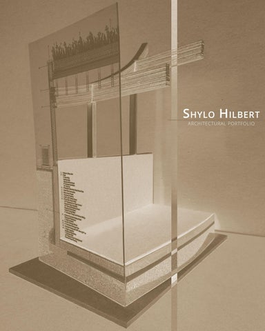
SPATIAL TRANSLATIONS

2nd Year - 2019 Fall Semester
INSTRUCTOR:
Advertisement
B rian Lee
PROGRAM/SOFTWARE/MEDIA:
H and Drafting
Basswood
Painted Blue Foam
Hot Wire Cutter
Bandsaw
COURSE AND PROJECT DESCRIPTION:
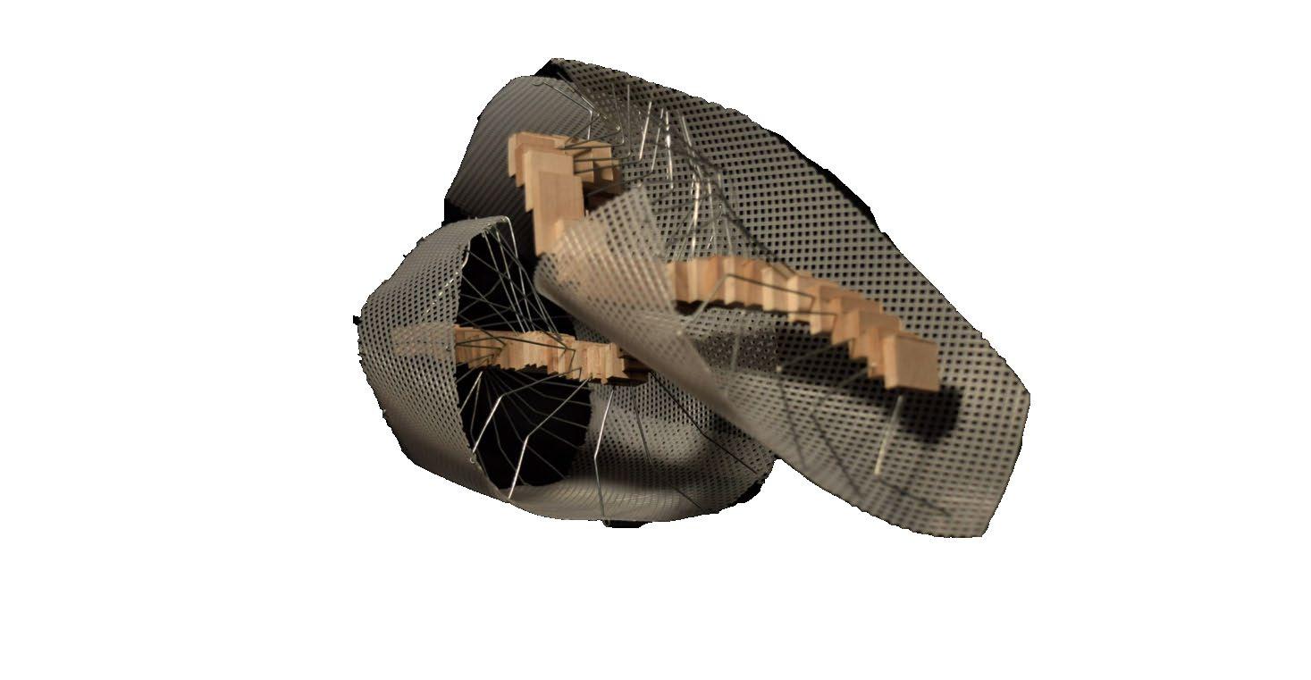
The premise of this project is to translate a physical human motion into an ambiguous interpretation to formulate an architectural spatial rendition. This process began with a comprehensive writing on the actions of the motion without explicitly stating what the motion is. Through images of the motion being performed, drawings were made to express the action with the presence of time, without drawing any identifiable or realistic bodily element (such as an arm or leg). Separating the motion from the body itself resulted in the creation of an abstract array of spiraling line segments, which were then projected three-dimensionally through the spatial embodiment model.
The spatial embodiment model was composed of three material components - basswood, metal wire, and perforated plastic mesh - to form a solid, frame, and shell/skin. The interdependence of each material was crucial to maintain the structural integrity of the model.

The cube model was designed to incorporate certain elements of the previous work and spatial embodiment model while conforming to specific dimensional and material limitations through the use of foam. These limitations consisted of the cube being no more than 6” by 6” and the spaces within must allow a person’s entry when to scale.
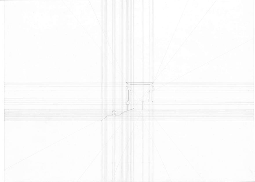
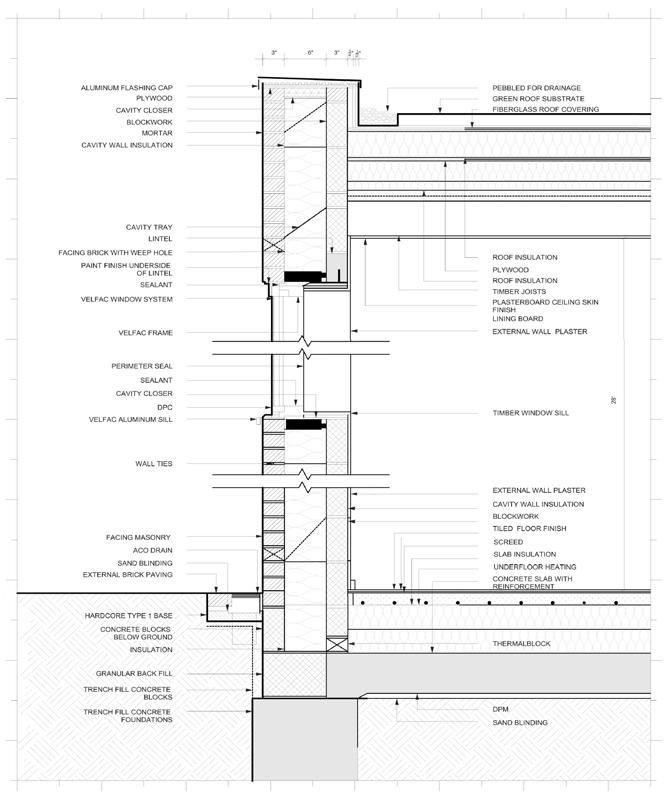
Hand drawings of the sections, plans, and elevations of both the spatial embodiment model and cube model were created to provide a more in depth understanding of the spatial and form qualities within both models.
This project demonstrates the ability to utilize abstract interpretations of physical motion to inform architectural spatial renditions. The use of hand drawings and careful material selection demonstrates attention to detail and a comprehensive understanding of the interdependence of various elements in the design process.

IMAGES:
C.1 - Back Left Angle of Spatial Embodiment Model
C.2 - Front Left Angle of Spatial Embodiment Model
C.3 - Right Profile of Spatial Embodiment Model
C.4 - Front Right Angle of Spatial Embodiment Model
IMAGES:
C.5 - OPEN CUBE MODEL
C.6 - CLOSED CUBE MODEL
IMAGES:
C.7 - VARIOUS CUBE ELEVATIONS, TOP AND INTERIOR HALF


C.8 - HAND DRAWN SECTION OF PHYSICAL CUBE MODEL


C.9 - HAND DRAWN PLAN OF PHYSICAL CUBE MODEL
C.10 - ELEVATION DRAWING OF SPATIAL EMBODIMENT MODEL
C.11 - SECTION DRAWING OF SPATIAL EMBODIMENT MODEL


ARCH 252 - B uilding A rts s tudio ii