PORTFOLIO
URBAN PLANNING | ARCHITECTURE
SELECTED WORKS 2022-23
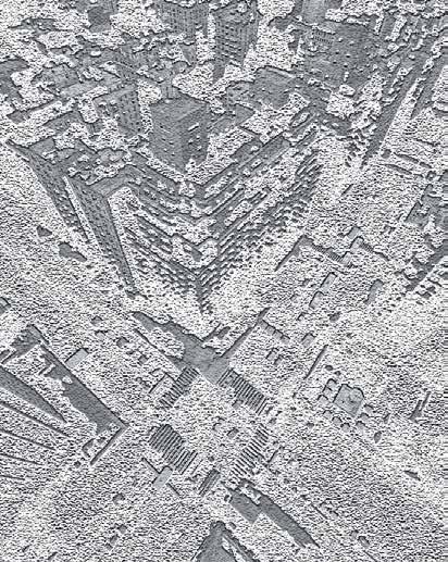
Master’s in City and Metropolitan Planning | B. Arch
SHREYA SHRESTHA
SELECTED WORKS 2022-23
Master’s in City and Metropolitan Planning | B. Arch
SHREYA SHRESTHAshresthashreya2@gmail.com | 650-537-7809
EDUCATION
Master’s in City and Metropolitan Planning (MCMP) | University of Utah
Bachelor’s in Architecture | Tribhuvan University
EXPERIENCE
• GIS Analyst
Utah Center for Civic Improvement
• Graduate TA/ RA
University of Utah
• Architect
Naxalaya Pvt. Ltd
Aaju Design Pvt. Ltd
Imperial Engineering Solutions Pvt. Ltd
Naya Rastriya Engineering Consultancy Pvt. Ltd
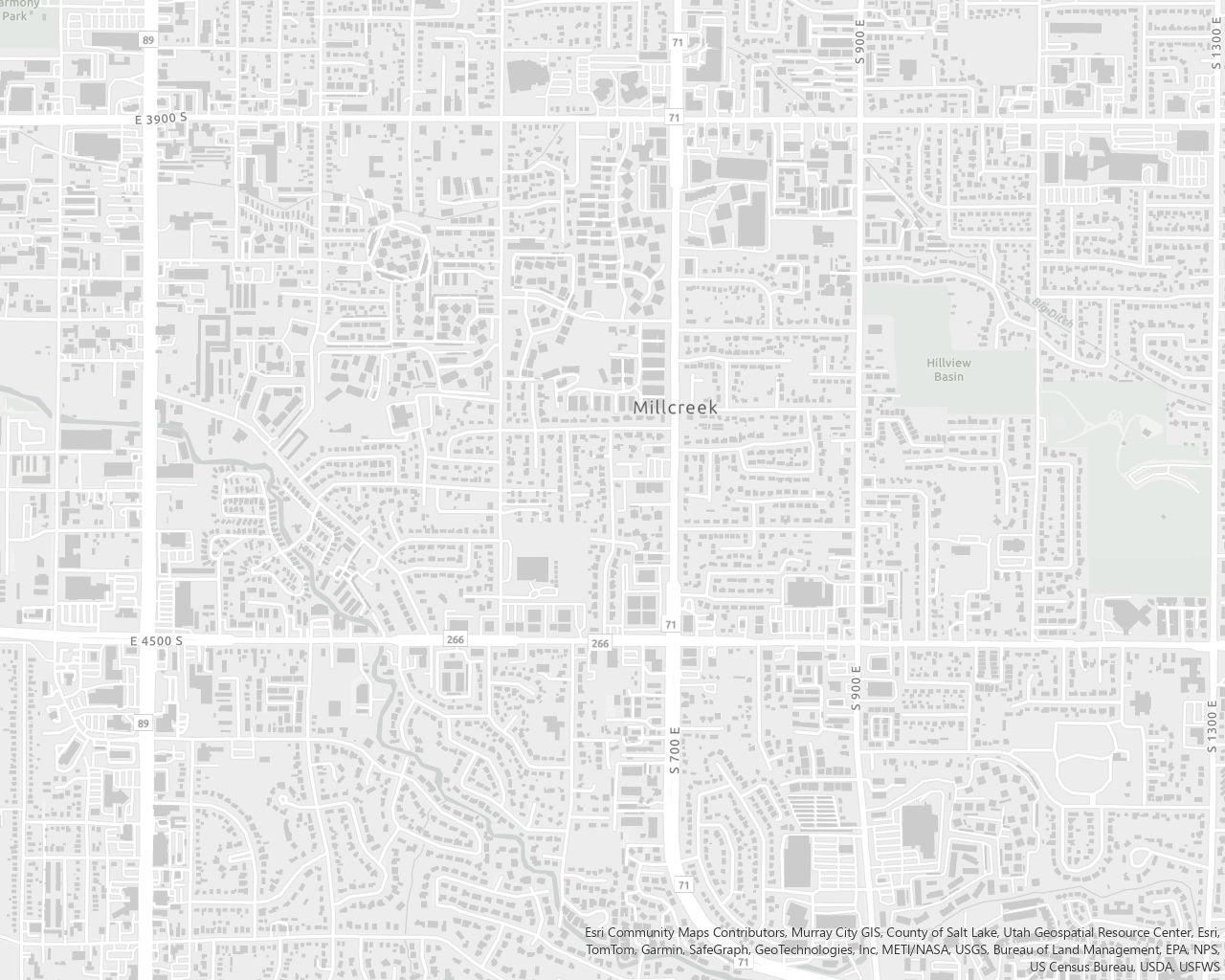
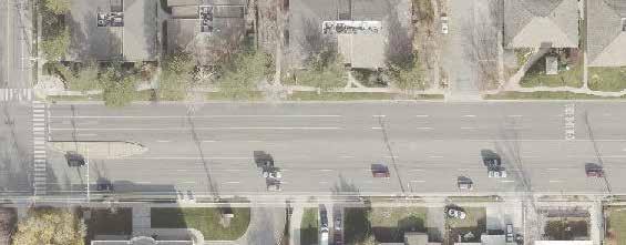
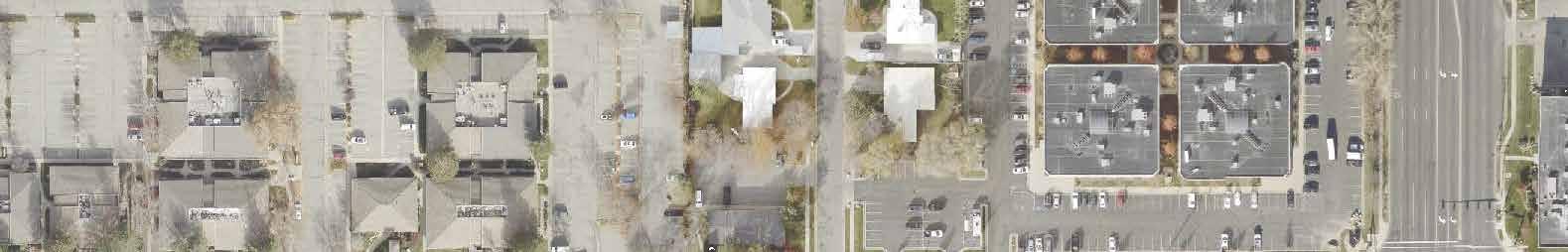
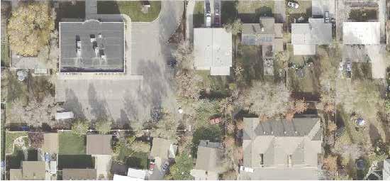
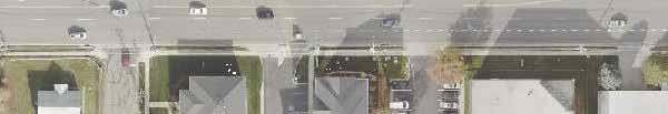
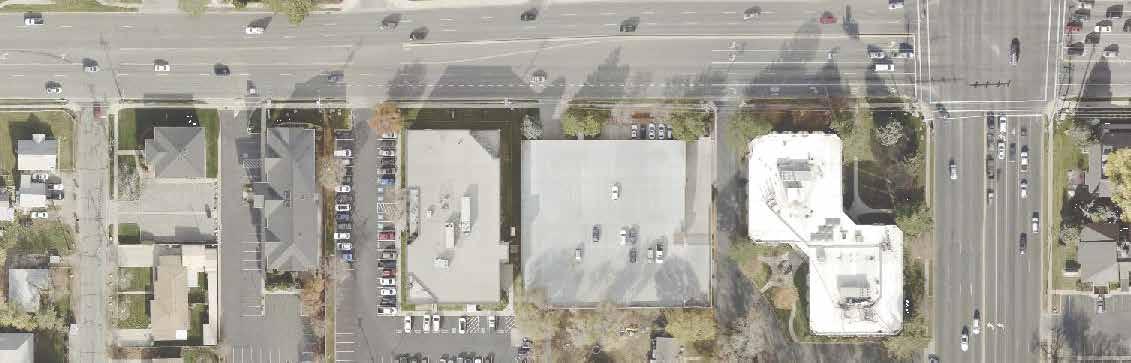
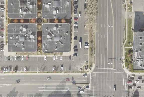
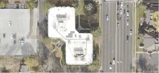
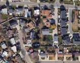
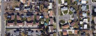
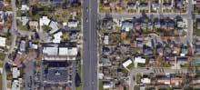
MILLCREEK, SALT LAKE CITY, UTAH
Assessment of the effectiveness of the design of a place at two scales: street and neighborhood.
Project Type: Masters in City and Metropolitan Planning
Team: Ana Shinzato, Jeresun Atkin, Shreya Shrestha
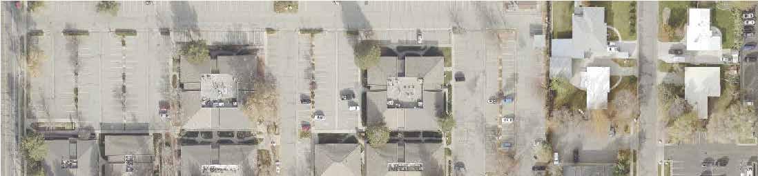
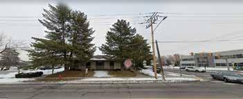
The street lacks adequate infrastructure and safety measures for active transportation, with narrow or poorly maintained sidewalks, no buffer between pedestrians and traffic, no bicycle lanes, and a need for improved connectivity for cyclists in the turning into 4500 S.
The crosswalk at 4500 S and 700 E allows pedestrians only 30 seconds to cross, which our analysis found takes about 25 seconds for an able-bodied person, potentially posing challenges for slower-moving individuals. The area lacks pedestrian-friendly infrastructure, with unsafe crosswalks and narrow sidewalks that are not wheelchair-accessible, leading to limited mobility options and prioritization of cars.
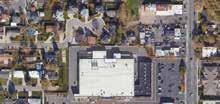
The area lacks natural vegetation, amenities, and social spaces, with unused areas and a lack of grass maintenance affecting the visual appeal of the neighborhood. The neighborhood beautification could add character to the neighborhood, improving overall spatial experience of the placemaking and potentially encourage pedestrian walkability.
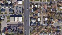
The neighborhood around the street segment 4500 S between 500 E and 700 E features a mix of residential multifamily and general office zoning. The three-lane main street, with a turning lane and nine lanes at the intersection, allows for fast, comfortable driving and easy access to commercial buildings. However, it poses challenges for pedestrians due to its width and speed limit of 40 miles per hour.
While sidewalks are mostly safe, they could be improved for pedestrian comfort. Public transportation is provided by buses, but there is no direct connection with active mobility, making it inconvenient for pedestrians accessing the five bus stops in the area.


GOAL ASSESSMENT Based on exisiting conditions
Narrow sidewalk (4ft-6ft) with landscape buffer between sidewalk and street (5ft9ft)
Wide sidewalk (8ft)
Bus stop
Intersection


QUADRANT
B


6’


POSSIBLE BIKE ROUTES
High comfort bike lanes with protected lanes
Medium comfort bike lanes based on moderate speed (includes signage but not painted)
Low comfort bike lane based on high speed (little separation from traffic using paint)
POSSIBLE PEDESTRIAN TRIP ROUTES FOR BETTER MOBILITY
Original trip route (current)
• Time: 17 min to travel
• Distance: 1.38 km
Possible route no. 1
• Time: 12 minutes
• Distance: 0.8 miles / 1.25 km
Possible route no 2
• Time: 12 minute
• Distance: 1.29 minute
Drive ways with side walks
Pedestrian walkways
GOAL
•
•
•
•
•
•
•
•
•
Liberty Wells is situated on the east side of Salt Lake City, just south of downtown. Its highlight is the notable Liberty Park in the neighborhood’s northeastern corner. Liberty Wells is considered a part of the Central Community and was included in its 2005 Neighborhood Plan. Since then, it has become a more definedneighborhood deserving of its own neighborhood plan.
We believe that Liberty Wells is well-suited to support a “20-minute neighborhood.” This concept means that every resident within the neighborhood can access their daily needs (grocery stores, schools, parks, and restaurants) within a 20-minute walk, or a 20-minute bike ride for less frequent needs.
We undertook a comprehensive process in creating this plan, which included community engagement with residents and visitors through interviews and surveys, as well as an analysis of the existing conditions in the neighborhood. Based on what we learned, the planning team identifie seven focus areas: Housing, Land Use, Business and commerical corridors,Neighborhood Amenities, Transportation, Green Space and Urban Design. Our group specifically focused at the transportation in and through the Liberty Wells neighborhood which is elaborated in this portfolio.
Project Type:
Masters in City and Metropolitan Planning
Team: Justin Delgado
Zeke Peters
Shreya Shrestha
River Jarman
The Liberty Wells neighborhood comprises quaint residential neighborhoods and small amounts of commercial development, bounded by 700 East (State Route 71) on the east and State Street (U.S. Route 89) on the west, and by 900 South to the north and 2100 South to the south. Despite the busy bordering roads, there are many quiet neighborhood streets throughout Liberty Wells. While having a neighborhood feel achieved by small lanes and narrow roads, it is surrounded and bisected by some of the busiest roads in Salt Lake City.
The existing conditions analysis looks at all modes of transportation and the connections that exist internally in Liberty Wells and regionally in Salt Lake City. This includes active transportation, transit, and vehicular infrastructure, as well as completeness, connectivity, safety, attractiveness, and efficiency.The public input analysis bases its data analysis on information collected from a public survey and a series of approximately 10 transportation focused interviews.
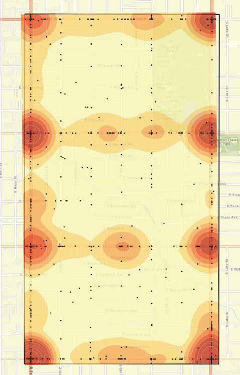
Density of crashes within Liberty Wells. (2018 to 2022)
> 6
< 1
Vehicle crashes only within Liberty Wells. (2018 to 2022)
Liberty Wells Extent
The current transporation plan for the Liberty Wells neighborhood is out of date, and has gaps between land use and transportation. Additionally, access to amenities in the neighborhood is inequitable, despite its robust grid network.
• Major and minor crossings alike lack safety counter measures, especially at the crossings.
• Crashes are unusually common in the area considering its size.
• An “island effect” is caused by the large arterial roads bordering the neighborhood, creating adverse conditions for pedestrian and vehicular access.
• Commerical properties are clustered along the neighborhood borders, which hinders access for pedestrians.
• Many encouraging transportation plans are underconstruction for the neighborhood, promising safety improvements and increased access for residents and visitors (9-line trial, BRT on State Street, neighborhood byways, etc.).
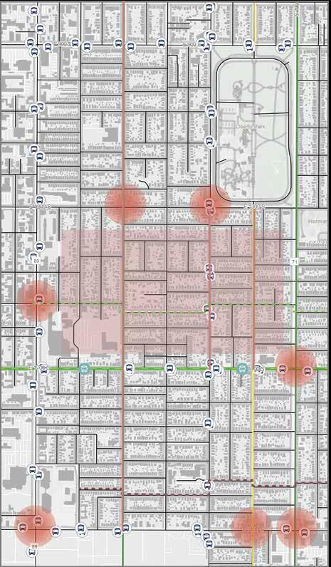
Streets
Sidewalks
Building footprint
Bikelane
Shared road with side lane
Shared road
Bus stop
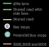
Potential Bus stop
300E, 500E and 600E bike lanes.
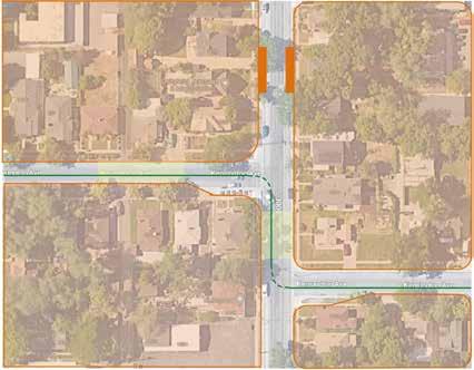
Visibility around corners can be low for both drivers and cyclist.
Kensington
Neighborhood Byway.
This will help with the crossing issues.
Dangerous intersections
Many of these intersections include popular school routes, high history of accidents, low comfort or poor visibility.
Wesminister Byway
Problematic area
Lack of East-West marked crossing. People speed despite being neighborhood streets with low visibility.
Based on survey data collected from 10 residents through interviews and surveys, categorized into owners and renters, along with additional research on the Safe Routes to School initiative and the Kensington Byway Project, our analysis focused on three major areas of interest.
“Increase safe connections for all modes of transportation in Liberty Wells. “
FOCUS AREA - 1
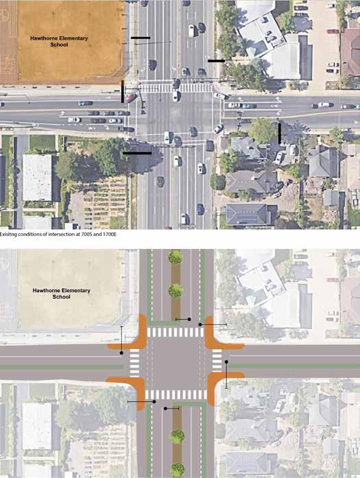
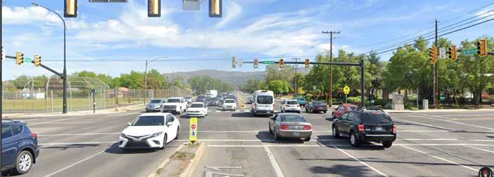
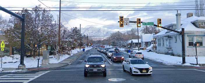
1700 S has a promising future as the commercial anchor of Liberty Wells. However, crash data indicates an immediate need for increased traffic safety measures along the street.
FOCUS AREA - 2
An incident on Jan 13th which involved a car hitting 2 children at 1700 S & 700 E gives us reasonable cause to advocate for increased safety measures. Survey respondents expressed additional concerns about safety near 1700 S.
FOCUS AREA - 3
Substantial distances between intersections and crossings often encourages residents to take risks when walking to their destinations, usually by jaywalking arterial roadways or walking excessive distances to reach safe crossing zones.
Safety at 1700 S Intersections & Mid-block crossings Pedestrian & Cyclist Accessibility
GUIDING PRINCIPLES
• Intersection safety improvements and mid-block crossing
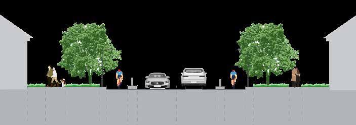
• Complete streets
• Connectivity
• Create a greenloop through alleyways and byways
Chokers
Speed humps
Cycle lane divider line
Kenginton avenue byway deflections reconfiguration to standard approach : Utilizing midblock curb extensions also referred to as “pinchpoints” or “chokers” for traffic calming treatment, the green line represents byway route for uninterrupted and low stress biking facility.
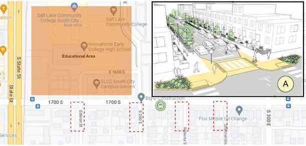
Educational areas Intersections near the school facility where treatment for safe E-W
Street illustration as suggested by NACTO Urban Street Guide A Proposed bus stop
CONCEPTUALIZED PUBLIC TRANSPORTATION INFRASTRUCTURE CONCEPT PROJECT
The proposed Bus Rapid Transit (BRT) line along the mid-hill Mahendra highway connecting Kathmandu to western Nepal is a visionary project. The BRT is invisioned to dramatically change the efficiency of the current transportation system, which fails to meet travel convenience and accessibility to the public.
The unhealthy environment caused by congestion and urban sprawl has led to reduced air quality, noise pollution, and overcrowded buses, causing serious health hazards. Introducing a dedicated BRT to the existing road will ensure manageable traffic, reduce travel time, and provide congestion-free space for other vehicles to operate efficiently. It has the potential to reduce population density within Kathmandu by providing possibilities for those living outside the valley to gain employment without having to relocate to the Kathmandu valley. This will reduce congestion and solve the urban sprawl issue, decentralizing the current centralized development.
Travel Convenience and multimodal accessibility
The BRT serving an intercity function will allow feeder modes to travel in and outside the city, promoting the use of other forms of public transportation.
KEY CHALLENGES
Promoting heathy environment and air quality
Manageable traffic can induce an improved environment with better air quality and create safe and comfortable areas for people.
Access to Amenities
Fast, safe, and convenient modes of travel will result in easy access to amenities like schools, offices, markets, etc., in larger proximity.
High infrastructure and operation costs
Unregulated operational management
KEY CHALLENGES
Syndicate practices
Threat to Satungal area historical settlement
Socio-political hindrance
Current senario Future senario
Sprawl condition with urban periphery (greenfield) development. Dispersed, low-density, motorbike dependent.
Patchy density distribution.
Assessment Attributes
Development/ growth patterns
Commercial and institutional activities are dispersed
Mixed land use
Large scale. In peri-urban areas, larger buildings, blocks, and wide roads. Less detail,
Automobile-oriented transportation is poorly suited for walking, cycling, and transit.
Horrendously designed hazardous to traffic
Density pattern
Activity location
Land use mix
Scale Transportation Street design
Smart growth with infill (brownfield) development. Polycentric development pattern.
Homogenous density distribution.
Commercial and institutional activities localized in urban centers and downtowns.
Mixed land use
Human scale. Smaller buildings, blocks, and roads care to design details for pedestrians
Multi-modal transportation that supports walking, cycling, and public transit use.
More manageable and traffic calming
DELINEATION OF BUS RAPID TRANSIT CONCEPT FOR KATHMANDU METROPOLITAN CITY
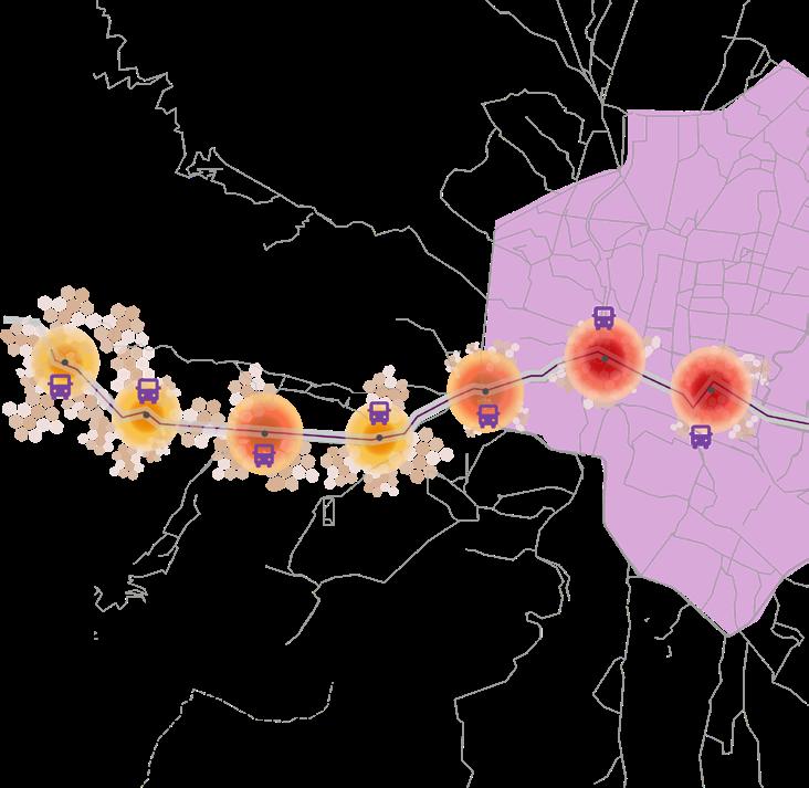
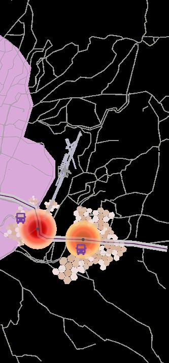
Thankot station and Chandragiri stations have recreational areas and also attract a lot of visitors so the area around these periphery of the stations are more likely to be developed commercially as restaurants and rentals. Naya naikap and satungal stations are under the pose to develop more virantly in terms of residential areas having significantly higher price of land.
Landuse Maleability

Low High
BRT stations
BRT roadway
Area within Ring Road
Sufficiently dense
Moderately dense
Insufficiently dense
Trishuli Nuwakot to Kathmandu
Nagdhunga to Kathmandu
Kathmandu to East through Bhaktapur
Dakshinkali to Kathmandu
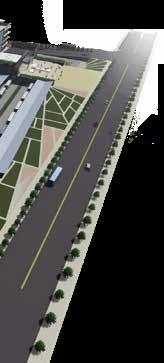
BALAMBU, KATHMANDU CITY, NEPAL
This thesis project, intercity bus terminal, was designed to minimize the effects of traffic congestion issue seen in the Kathmandu City. Nepal is a landlocked mountainous country so road transportation has a predominant role. 90% of trade traffic is dependent on roads.
Rapid urbanization has caused traffic congestion with more than 50% of vehicles in Nepal, plying in the Bagmati zone, with the highest concentration in the capital The need of traffic management in the city area and high-quality transit service has aroused the demand of a bus terminal.
The location of the terminal is determined through site feasibility analysis, capacity analysis and chosen in The west corridors of the valley considering the 20 year strategic development plan of Nepal. According to the traffic rate analysis Tribhuvan Road between Thankot and Bhainse linking Kathmandu with Terai is the main route that causes traffic congestion of Kathmandu.
Hence, the location of the site is purposed in such a way that it lies in the possible transit oriented development area It will also be accessible at 2.5km distance to the future outer ring road. Thus , validating the site feasibility and objective of this project which is to limit the intercity functions outside the ring road area reducing the volume of traffic inside the city.

Idle parking for long route bus
Exit for long route departure buses
Fueling station
Workshop area
Entrance for local buses
Local bus stand
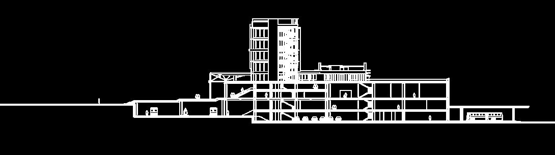
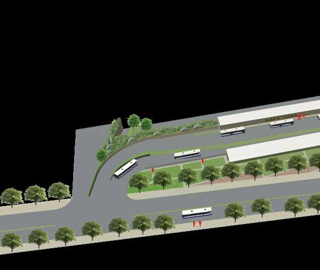
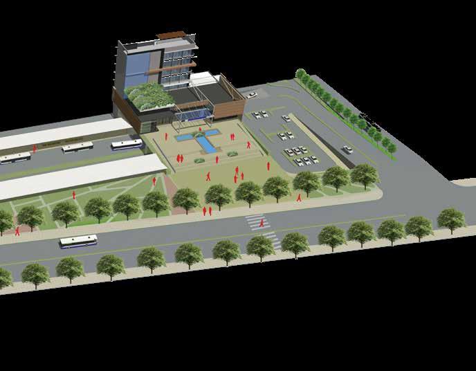
Main terminal building
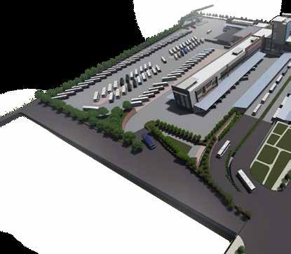
The main terminal building movement of passenger lent zone, so that the passengers the vehicular circulation. the segregation of passenger along with segregation been the major design nied by functional segregations departure functions in the
Plaza
building segregates the passenger in the vehicle prevapassengers don't obstruct circulation. Strategies involving passenger and vehicles according to routes has intervention accompasegregations of arrival and the vertical zoning.

Arrival function
Stop function
Departure function
Arrival block
Connecting block
Washing and maintenance
Departure
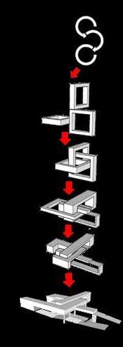
CONCEPT
Interconnection: the state of having its constituent parts connected together in an effective way. Constituent parts are the three primary function of a terminal and they are connected in loop. Efficient connection is represented by 3 rectangular loops composed in X,Y and Z direction. The rectangles are composed,transformed and adjusted according to the site to get the final form
Plaza
Park Pavilion
Local bus stand
Taxi stand
Entry for short route bus
Entry for long route bus arrival
Departure bus exit
Way to basement parking
Exit from arrival area
Main terminal entrance to departure area
water
water
THANK YOU