ARCHITECTURE PORTFOLIO
 Ar. Shilpa S
M.Arch in Architectural Design


 Ar. Shilpa S


Selected
M.arch I Semester IV I Academic work
Transit Oriented Development
M.arch I Semester II I Academic work
Mr.Selva Kumar Residence 2020 I Bricks & Space Architects
01 - 12 13 - 20 21 - 32 33 - 42
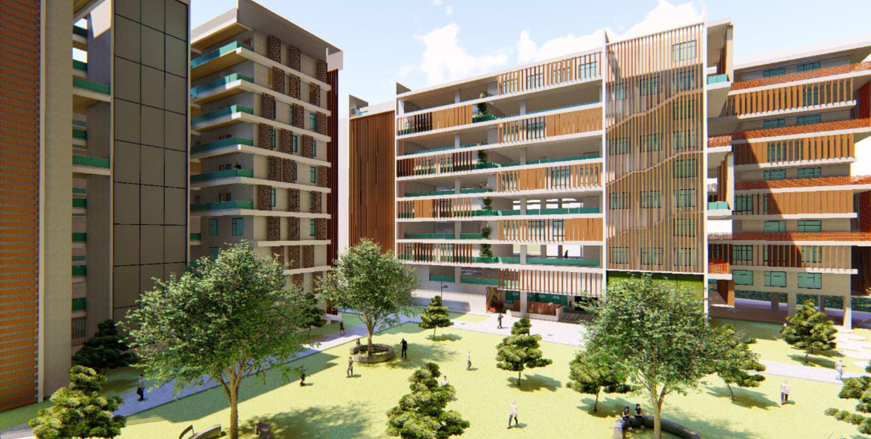
School of planning and architecture are a group of autonomous public institutes of higher education under Ministry of Education, Government of India. The SPAs primarily offer undergraduate, postgraduate, doctoral and executive education programme.
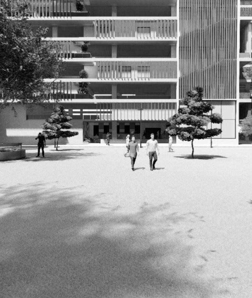
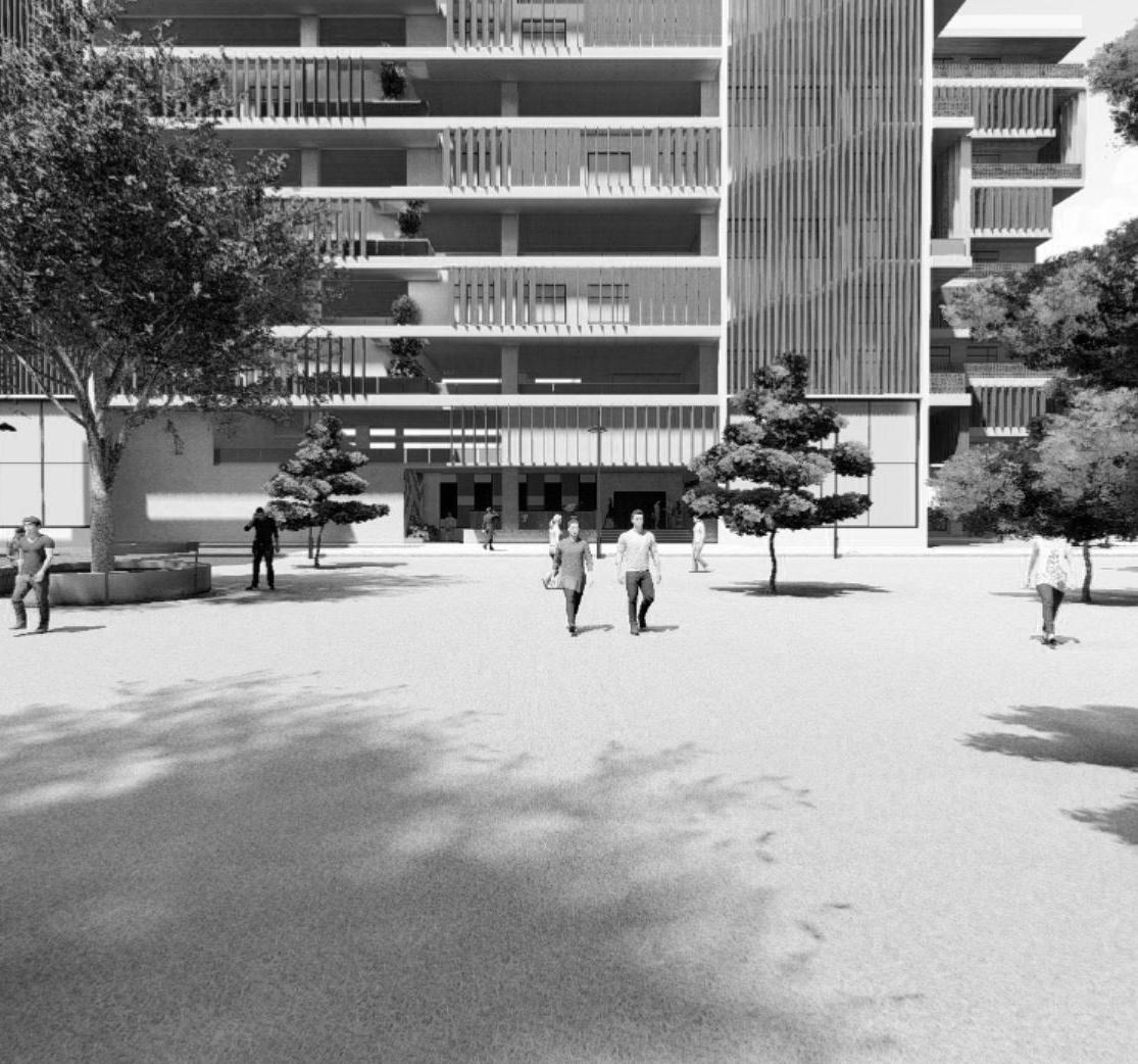
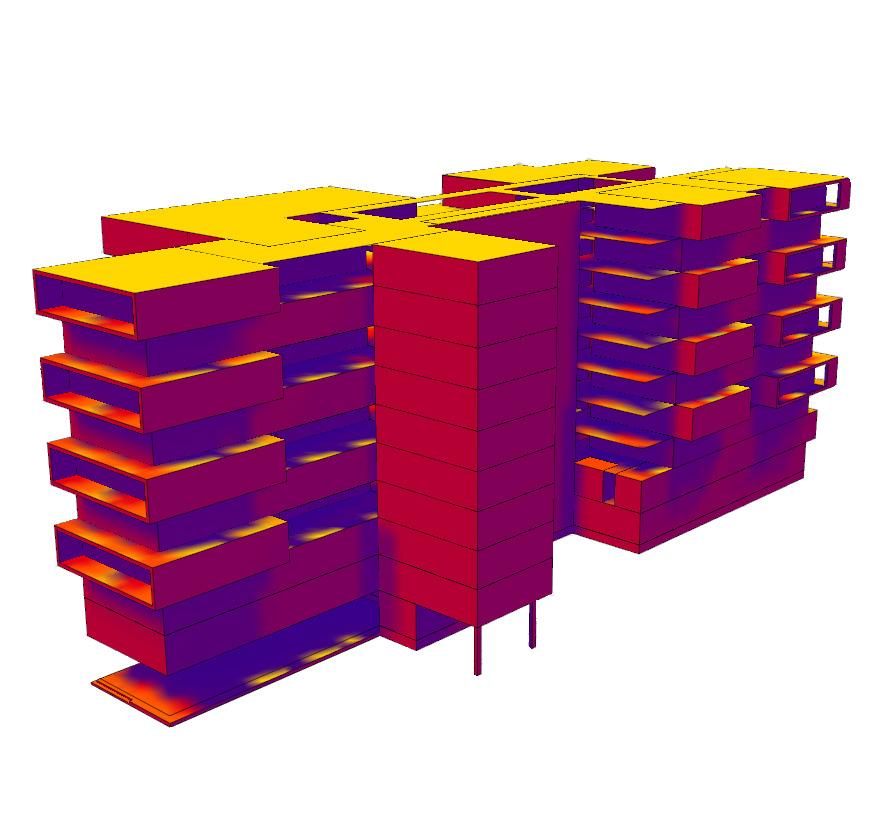
The aim of this thesis project is to design an integrated, spacious and passively designed new campus with modern infrastructure and technology catering to its growing functions and programs. Also, to enhance the thermal performance of the building with the use of appropriate design strategies such as optimum combination of materials in the facade, exploration of shading devices, role of courtyard and breakout spaces, etc,.
Site location - New Delhi
Site area - 20 acres (80937.12 SqM)
Total built up area - 98797 (SqM)
Typology - Educational building
Program - Academic blocks, auditorium, admin block,
library, hostel blocks
AutoCAD, Revit, SketchUp, Photoshop, Formit, Insight
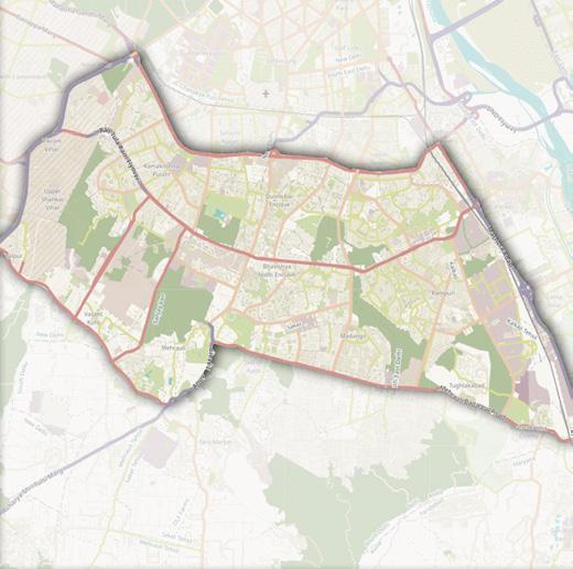
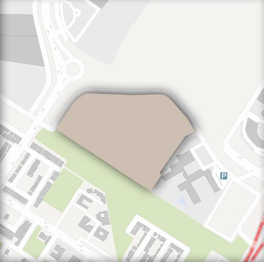
The site falls under the institutional zone which is close enough to commercial zone i.e. half kms away. The site has an irregular shape with 5 sides. Out of which, 3 sides has direct connectivity to the sarkar road which measures about 16m in width
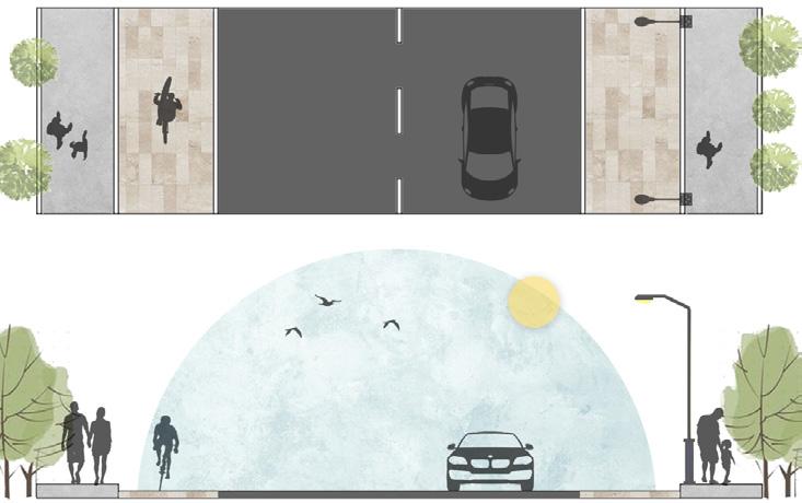


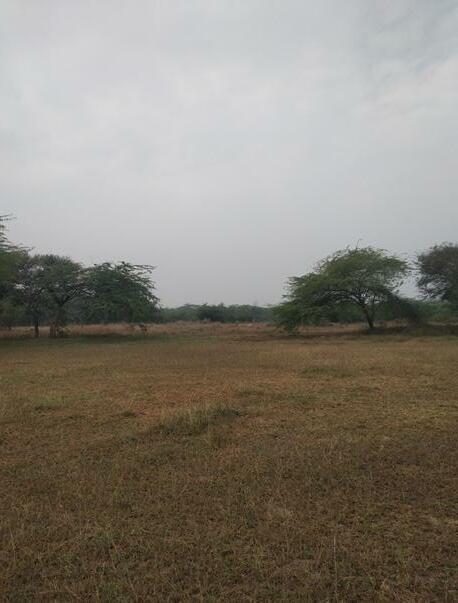
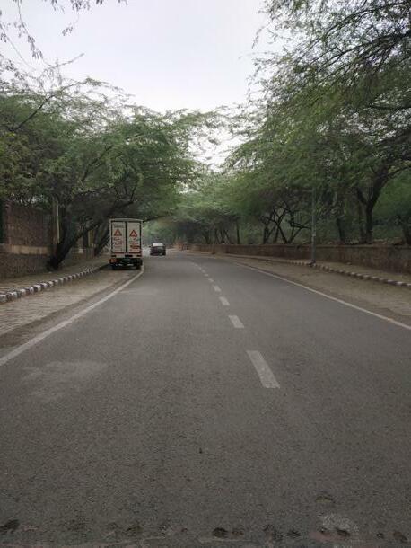
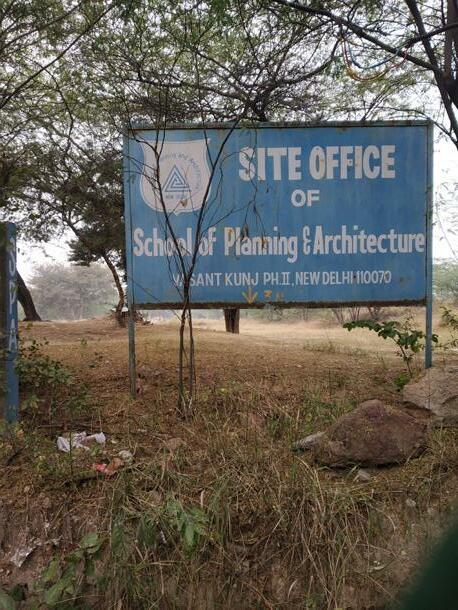
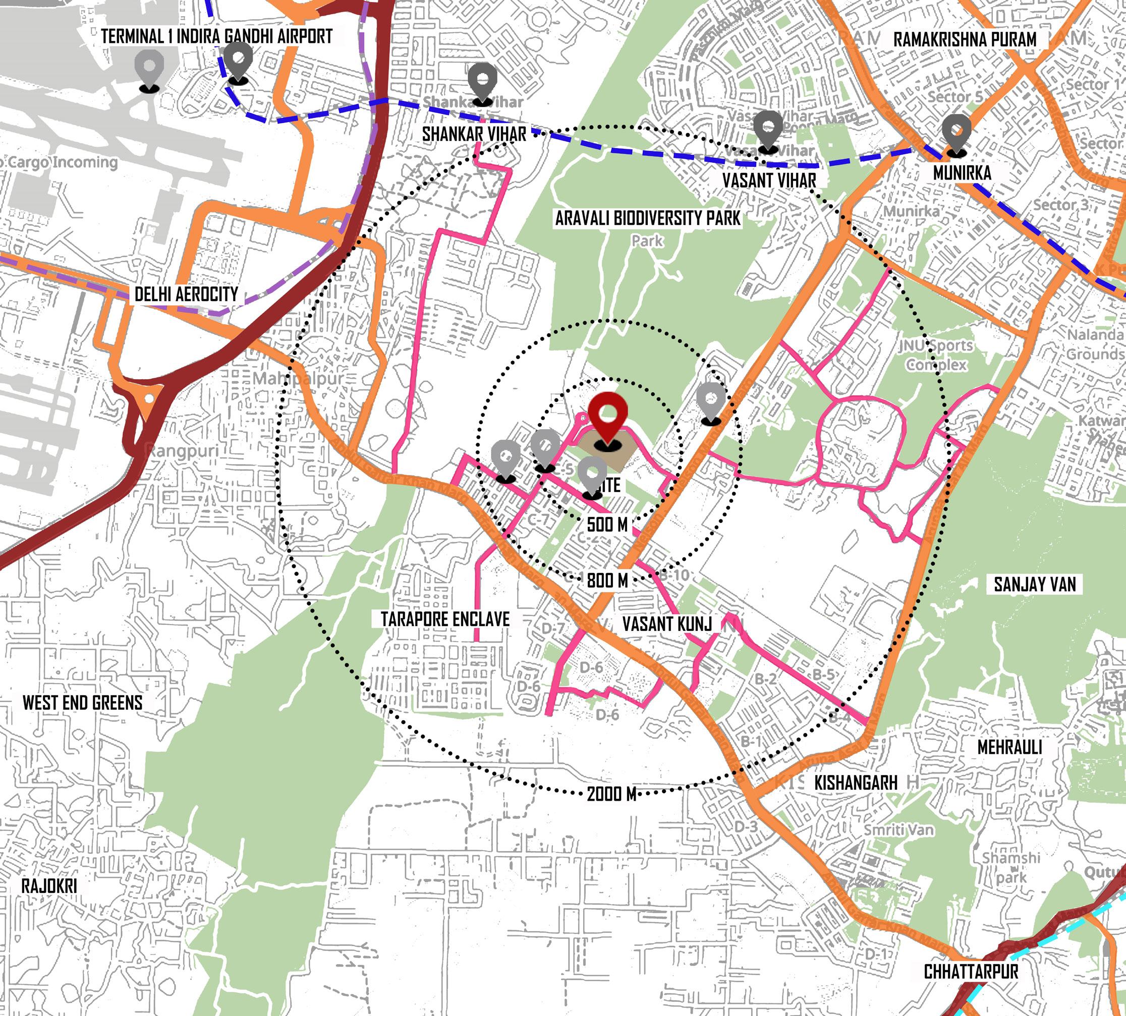
The site has good connectivity to major areas by means of ocal bus, metro, cabs and autos. The roads around the site and the surrounding area has pedestrian paths. The area on the front and rear of the site has green areas. There are many parks in the localities, thereby providing an enhanced microclimate in and around the site.
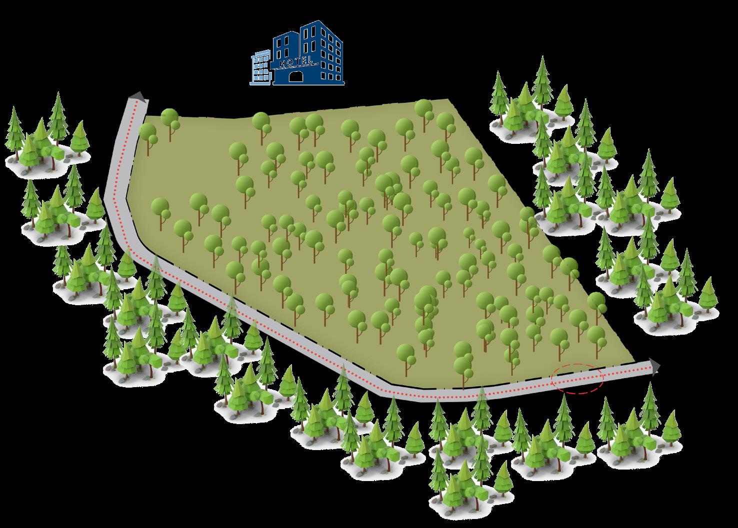
No development or commercial activity next to the site, except for the Grand hotel. No vegetation within the site could be retained because the type found is thorn trees and shrubs whose roots will penetrate deep into the ground and absorbs more water.
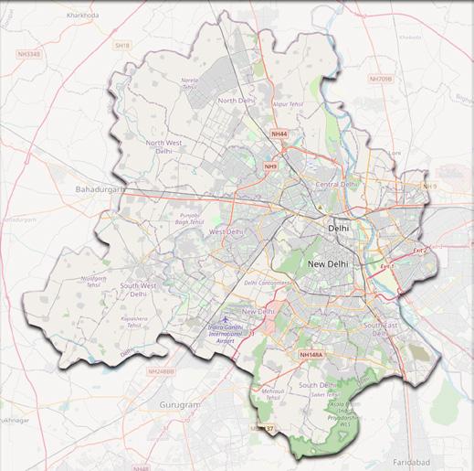
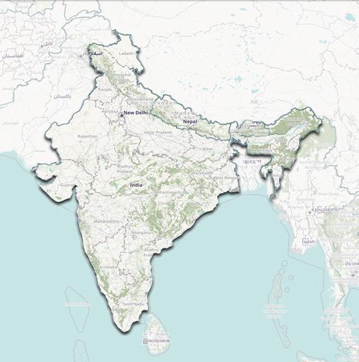
The road network, connectivity through different modes of transport, amenities / facilities in a closer proximity, land use type, blue green map of the area were studied in detail for the feasibility of the site & its location.
Arterial road

Sub arterial road Local road Metro line
Metro station Bus stop Site location
With the upcoming of an institution in the area would increase activities around. Increase in the commercial activity would lead to increased job oppurtunities which would enhance the economy
Less activity on the roads and immediate surroundings of the site. No much activities around the site might lead to illegal or crime activities Increased usage of vehicles in the area might lead to increased pollution and might cause threat to vegetation.
STAGE 1 STAGE 2
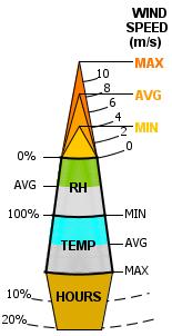
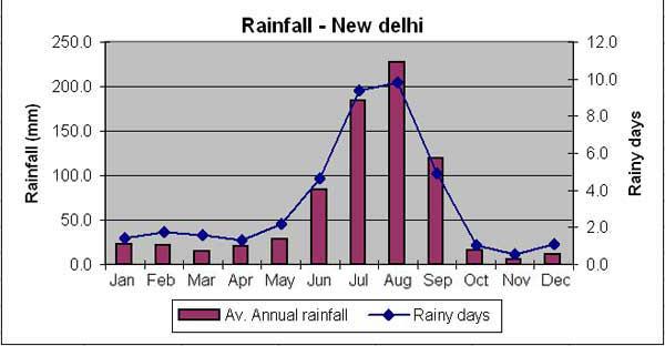
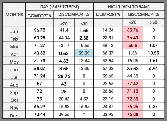
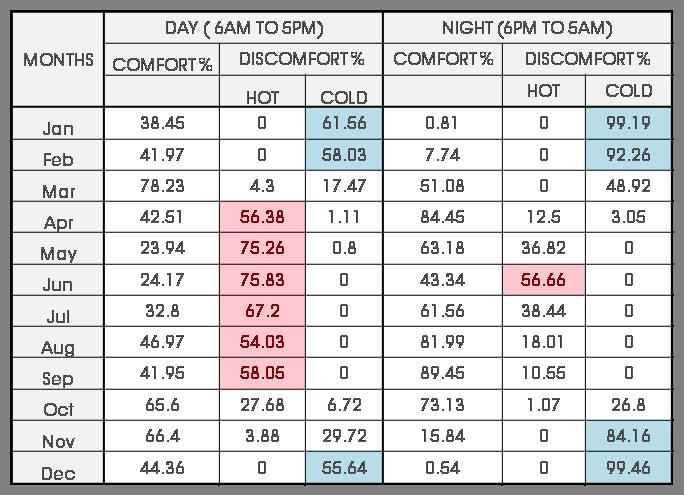
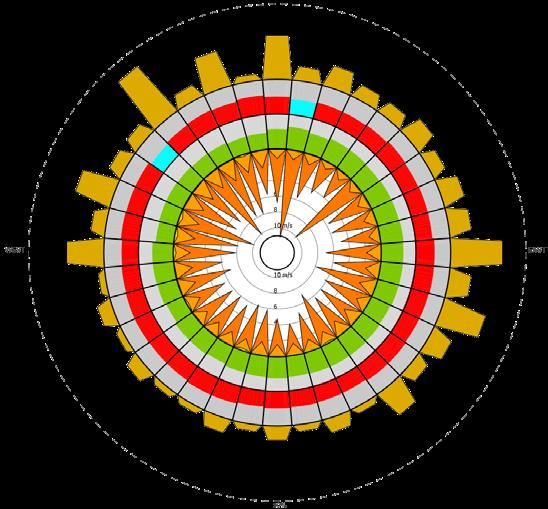
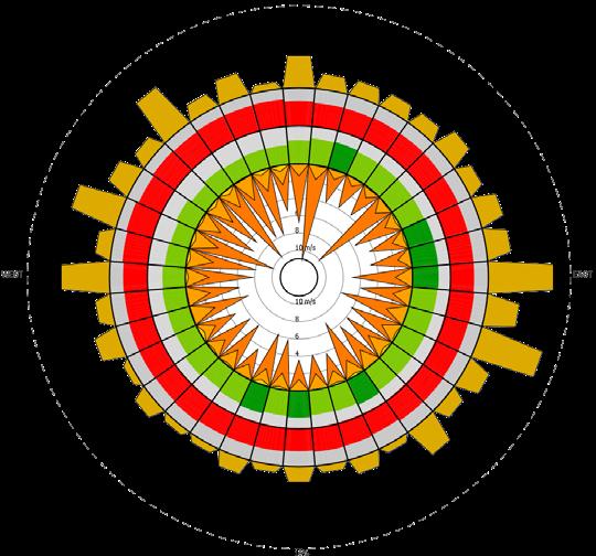
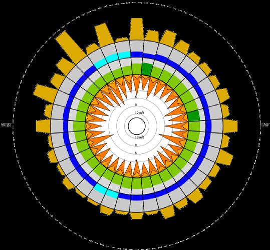
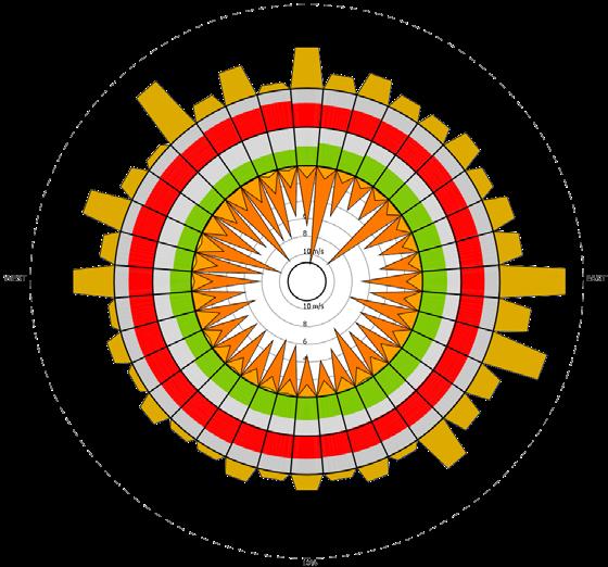
From the table 1 (temperature), it is observed that March and october are the months which are found to be comfortable throughtout the day. During day time, the hot discomfort is experienced more and it is noticed to happen from April till September. The cold discomfort is observed only in the month of January, February and December. During night time, cold discomfort is noticed to be high and it happens between November to February. The hot discomfort during night is found only in the month of June. Therefore, it can be concluded that June is found to be the hottest month and December is observed to be the coldest month. From the table 2 (relative humidity), it is found that high humidity (ie., above 70 %) prevails in Delhi for about 8 months in a year and it is noticed to happen during night time Low humidity is experienced only during the day time of April month. From the rainfall data, it is observed that it slightly increases from the month June and peaks during August and reduces gradually in the rest of the months. The annual rainfall index is 1.3 (Sheltered).
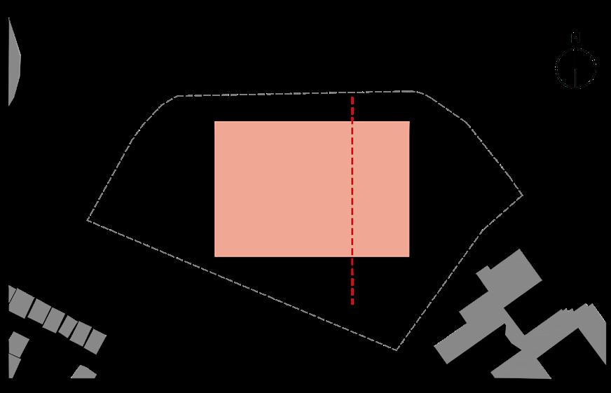
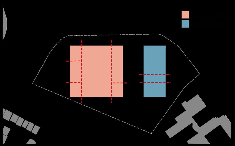
Building pulled out of the maximum ground coverage that it can occupy on the site. Dividing the building area into residential and non-residential zone.
STAGE 3
The residential zone is divided into hostel blocks for students and staff quarters. The non residential zone is further classified into academic area, admin area, recreational area and parking area.
STAGE 4
The public zone (ex: auditorium) is put to the front, followed by semi public and private zone. The open green spaces is provided to the north and south of academic zone to serve as a view point and also as buffer zone
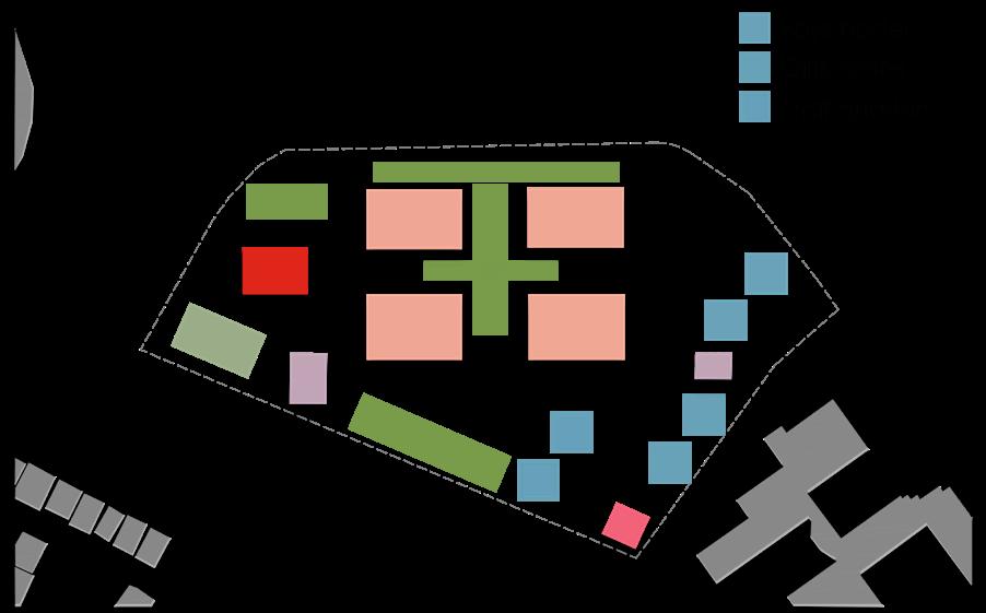
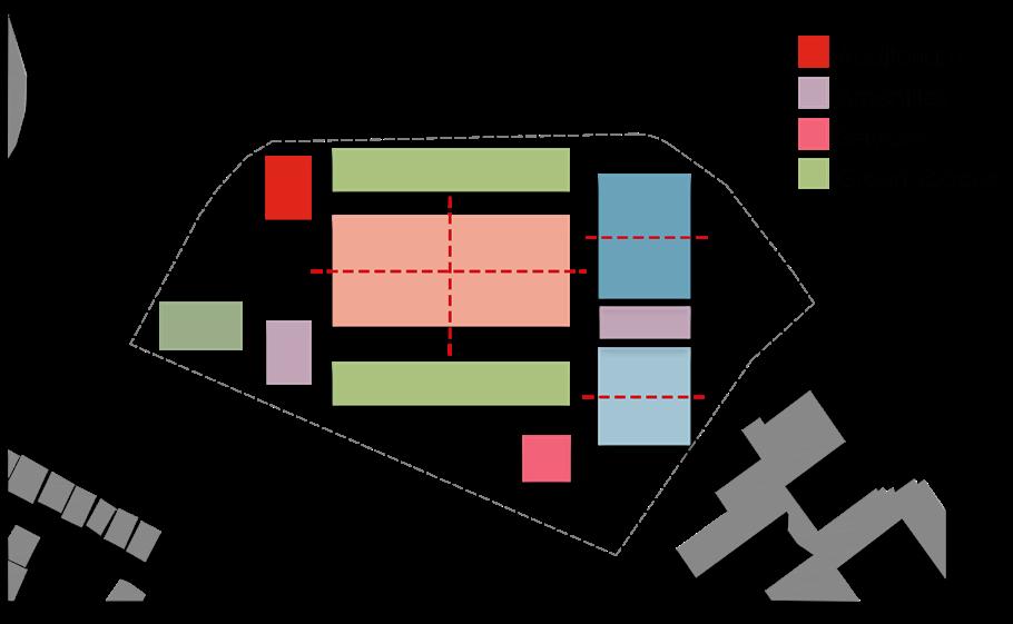
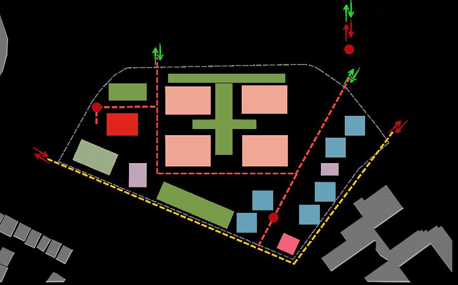
The academic zone is classified into UG block - architecture, UG block - planning and PG block with labs and library building close to each UG & PG block. The residential zone is further classified into boys hostel, girls hostel & staff quarters
STAGE 5
STAGE 6
Operable windows could be positioned predominantly on the east, north and north west directions so that wind could be allowed to circulate inside the building during summer months and it could be blocked from entering the building during winter and monsoon months. Windows on the east and north west could be kept open during the day time of the winter months to get fresh air and radiation of sun inside the building, The heat from such radiation has to be trapped in such a way that it can be used during night time, The shading devices has to be designed in such a way that it lets in wind and cuts of radiation during summer months
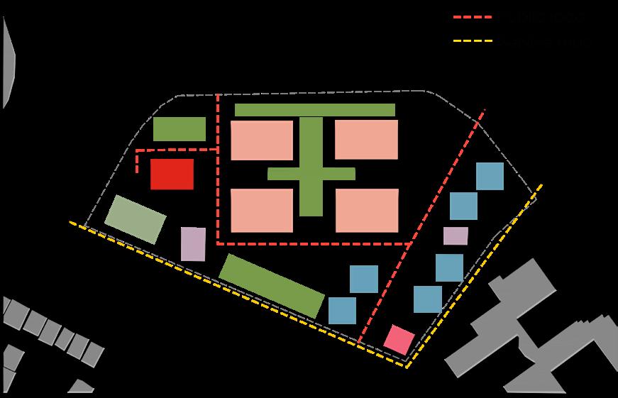
The public road is divided based on different users to reduce traffic congestion and ease of access without chaos. The vehicular movement is restricted inside the academic zone. The service road is put to the rear end of the site.
Multiple entry points to divert the movement of crowd. Security check points inside the site to restrict the entry of residential and academic users into the service zone. Continuous road is ensured for the movement of fire engine.
The auditorium and its parking area is put to one end of the site to control the movement of crowd throughout the site.
The academic parking is positioned in such a way that the vehicular movement is reduced inside the site.
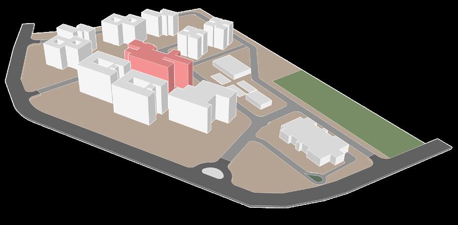
The academic blocks are located centrally to ensure closer proximity to all other areas & creating a walkable environmnent
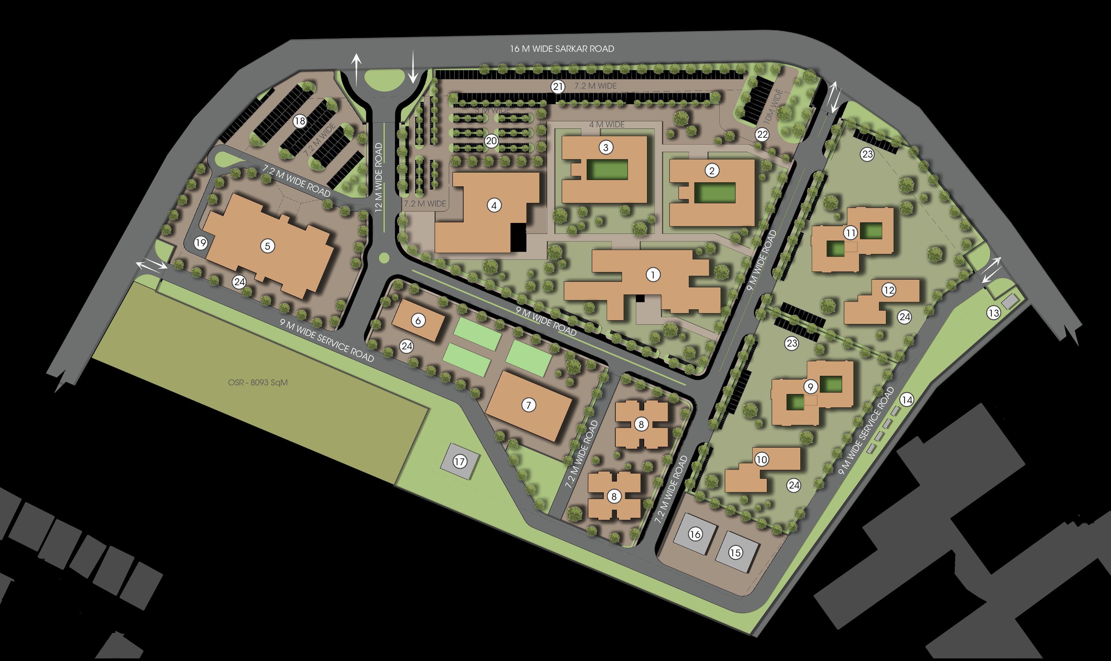
Based on the climatic study, building blocks are positioned in such a way that its longer side faces N-S direction.
Site area - 80937.12 SqM (20 acres)
OSR - 8093.7 SqM (2 acres)
FSI Permissible - 2.25
FSI Achieved - 1.22

Total built up area
Permissible - 182108.52 SqM Achieved - 98797 SqM Ground coverage - 15%
Academic block
No. of car parking - 215 No. of bus parking - 10 No. of bike parking - 392 No. of cycle parking - 110
Residential block No. of car parking - 40 No. of bike parking - 107
Unloading bay
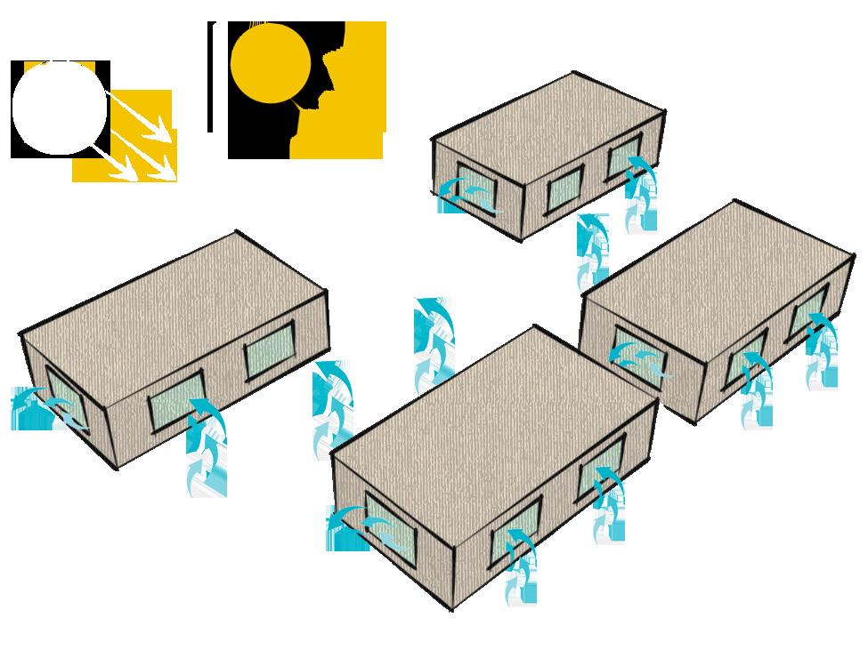
Linear block with longer side facing North - South direction and shorter side facing EastWest direction is taken.
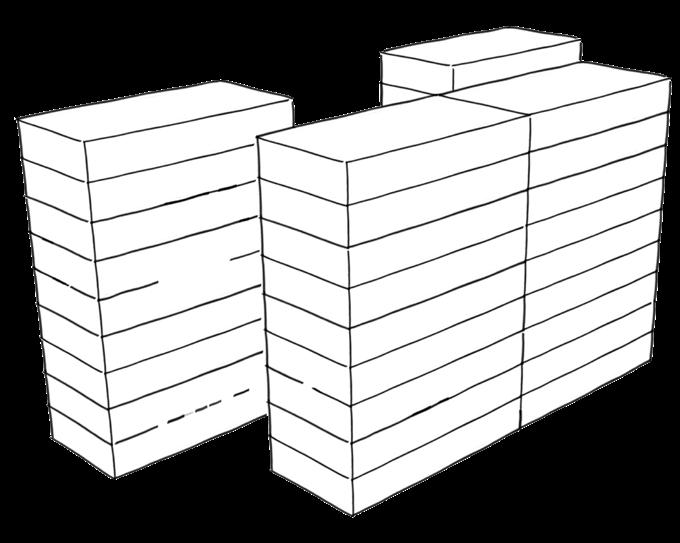
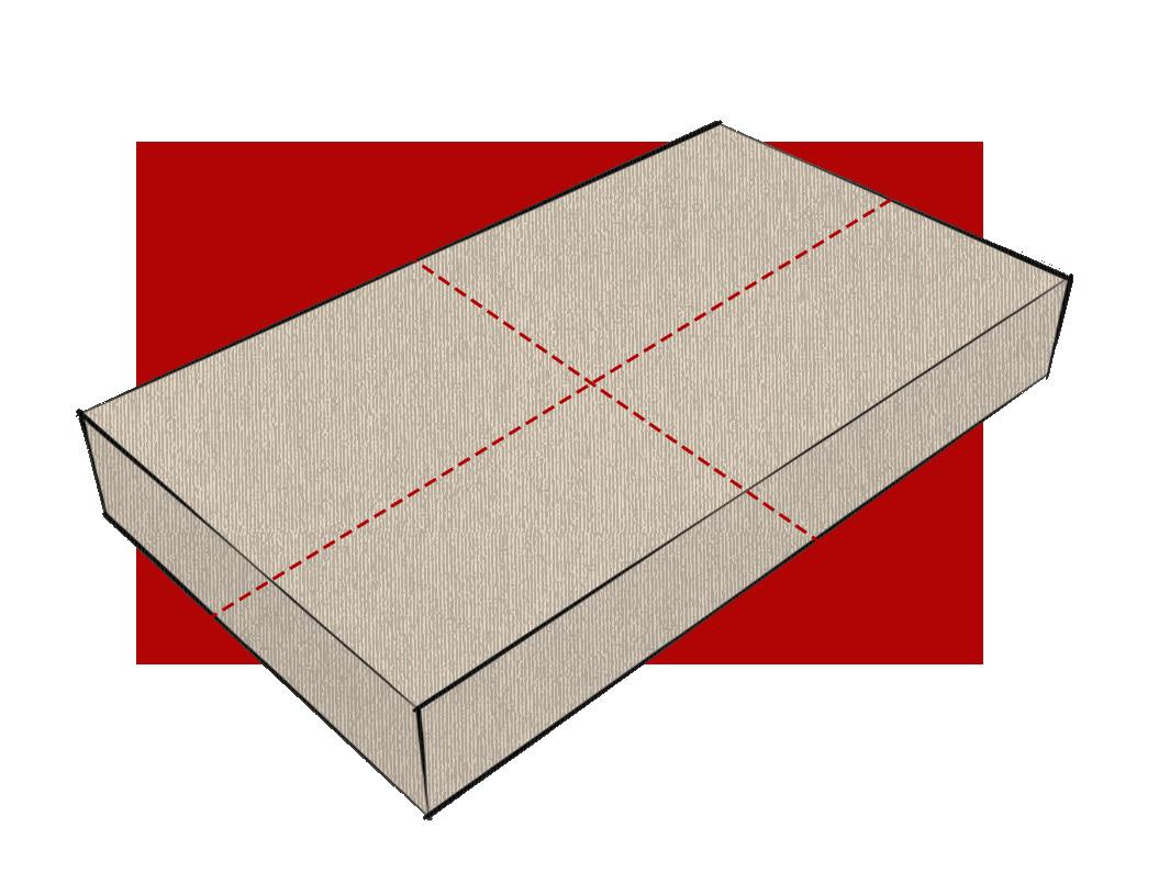
The block is divided into four parts considering each as studio unit. The longer side of each unit is made to face N-S direction
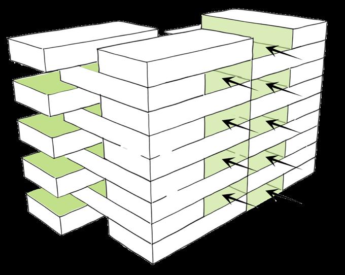
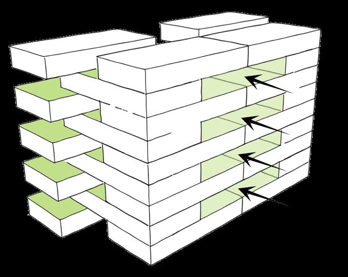
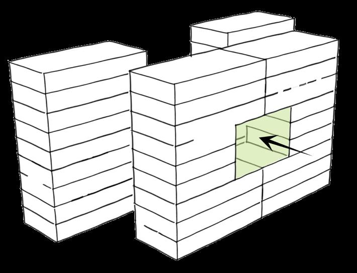
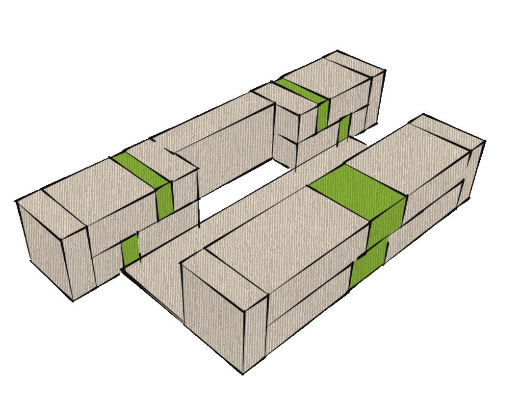
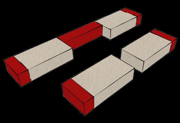
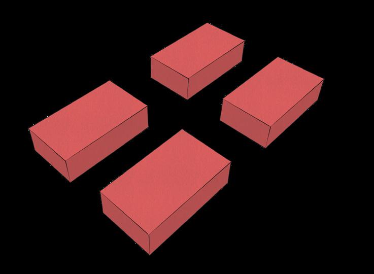
The blocks are staggered in such a way that each studio gets ample amount of daylight on all sides & to ensure that the form facilitates cross ventilation in each studio unit.
The non - habitable spaces are arranged in the East & West The common staircase is positioned on South to get enough light & reduce radiation entering into habitable space.
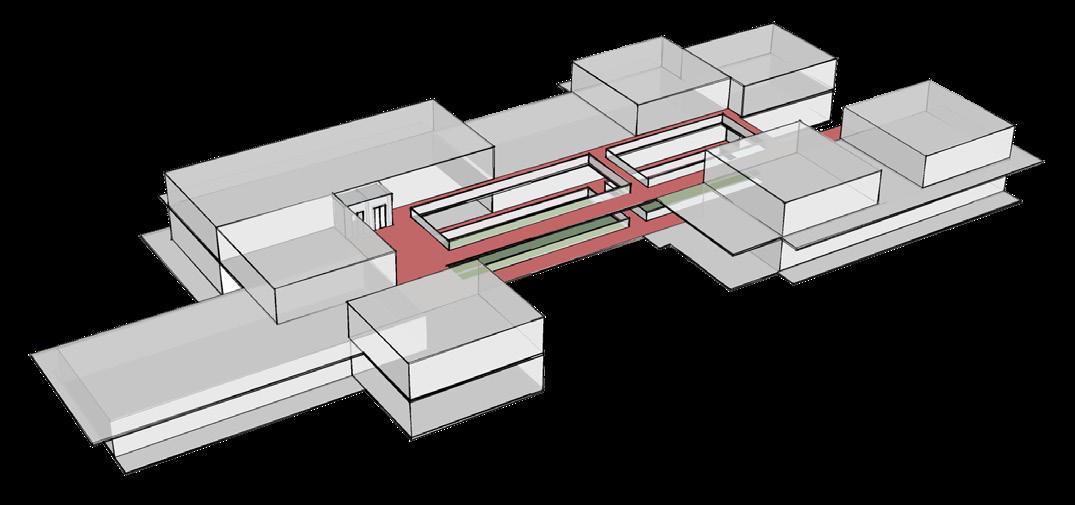
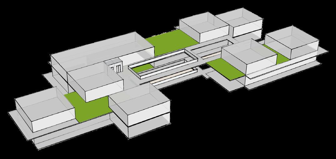
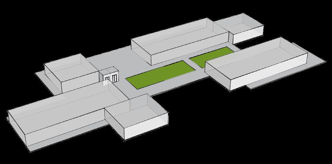
Open spaces such as courtyards on the ground level is put in between blocks to provide good views, facilitate air movement & also to bring down the temperature of hot air
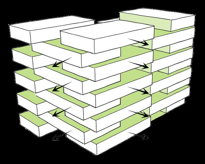
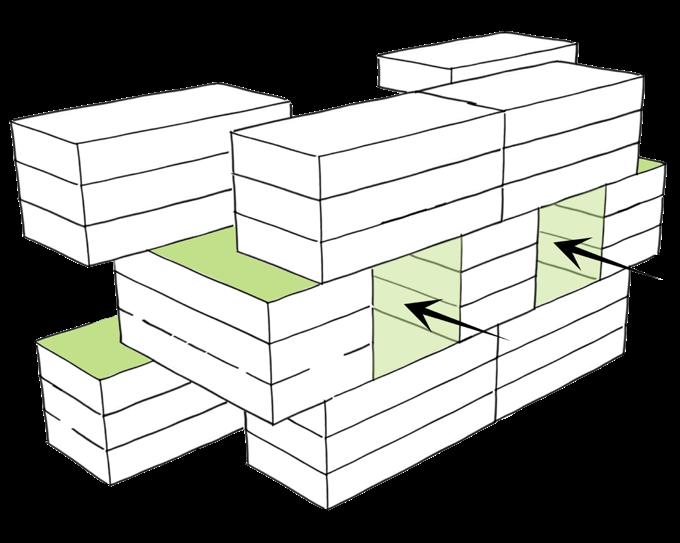
The open spaces are made to continue in all other levels by introducing voids in between.
It helps in the better circulation of air and also acts as a breakout zone
Staggered arrangement of blocks
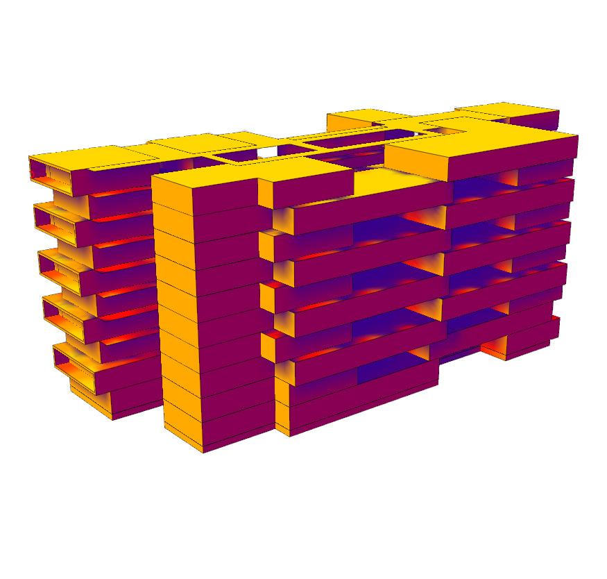
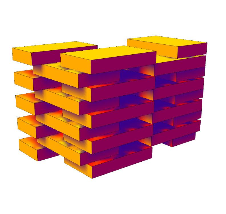
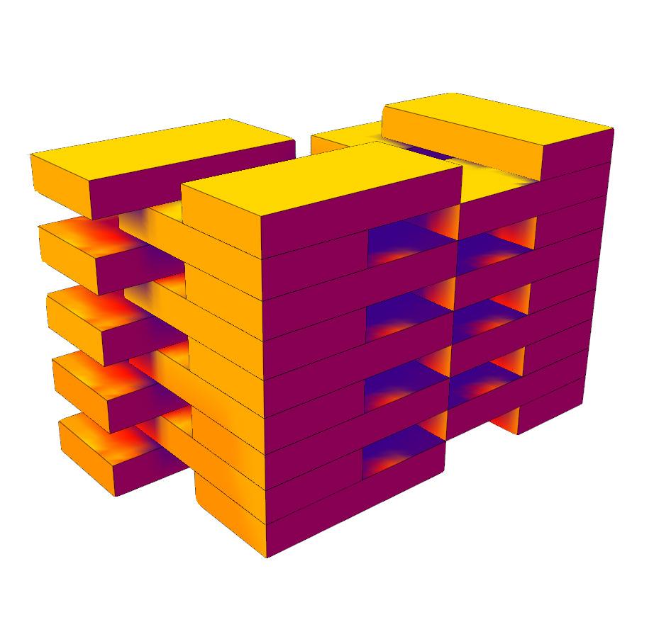
Integration of open space into the block
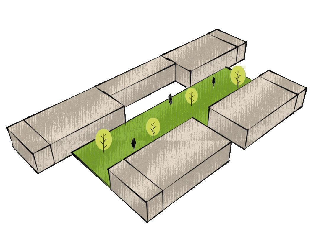
Addition of multiple voids Splitting the voids to other levels Alternate arrangement of open spaces in all levels
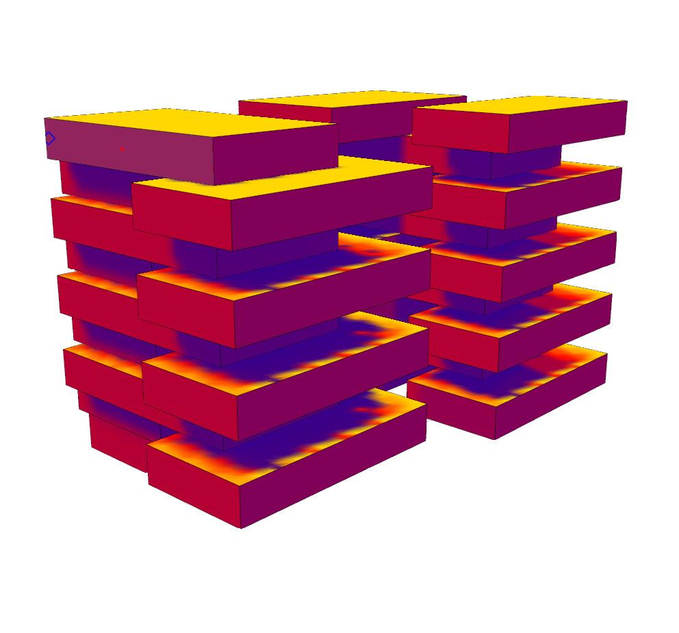
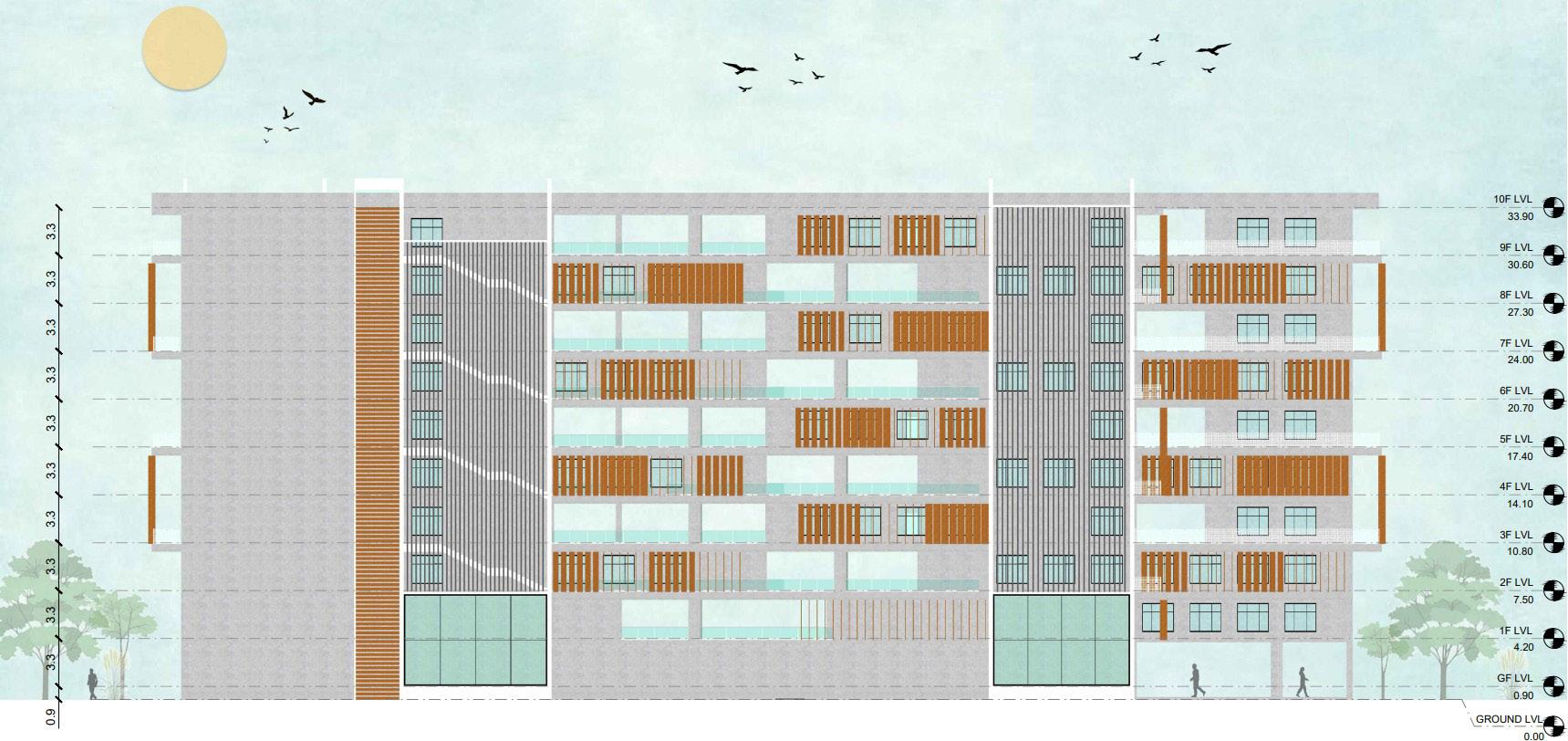
Projection & recession of floor plate to achieve self shading
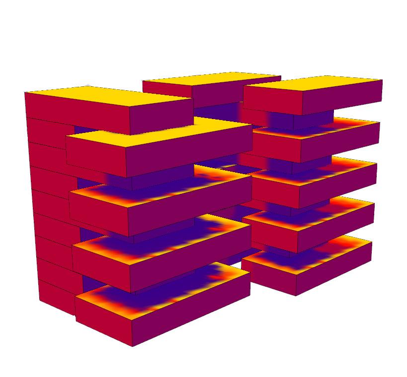





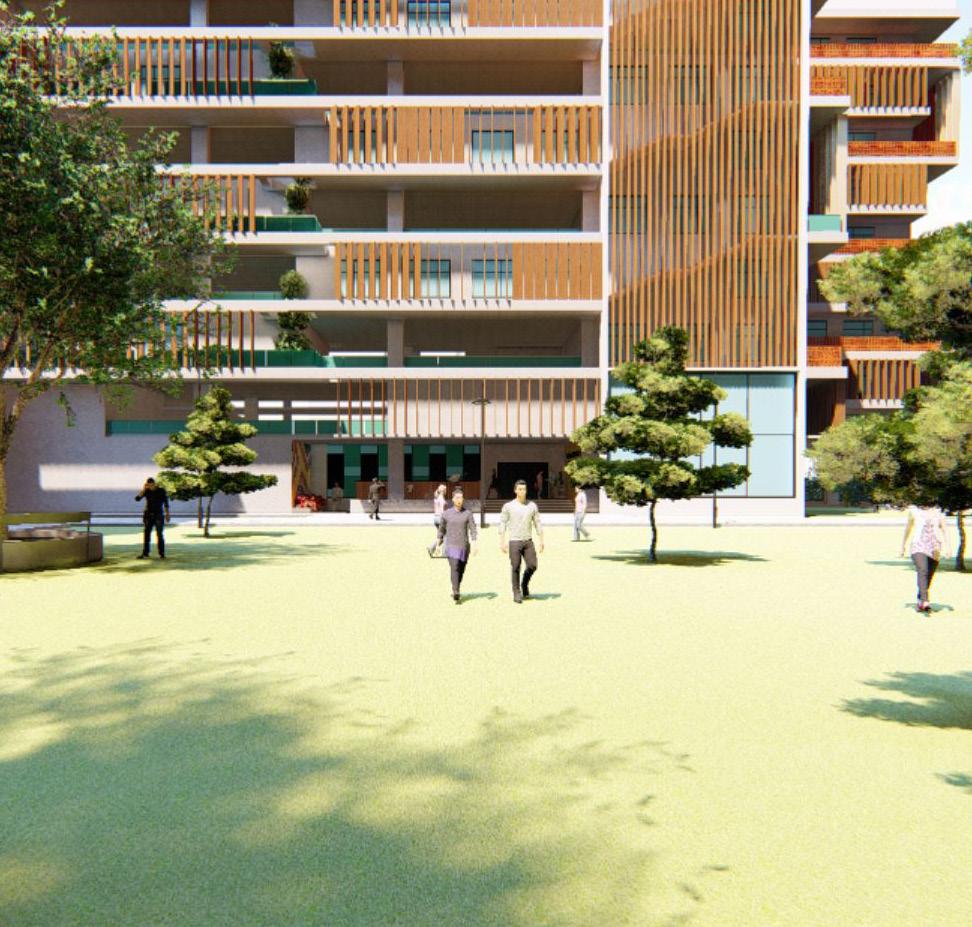
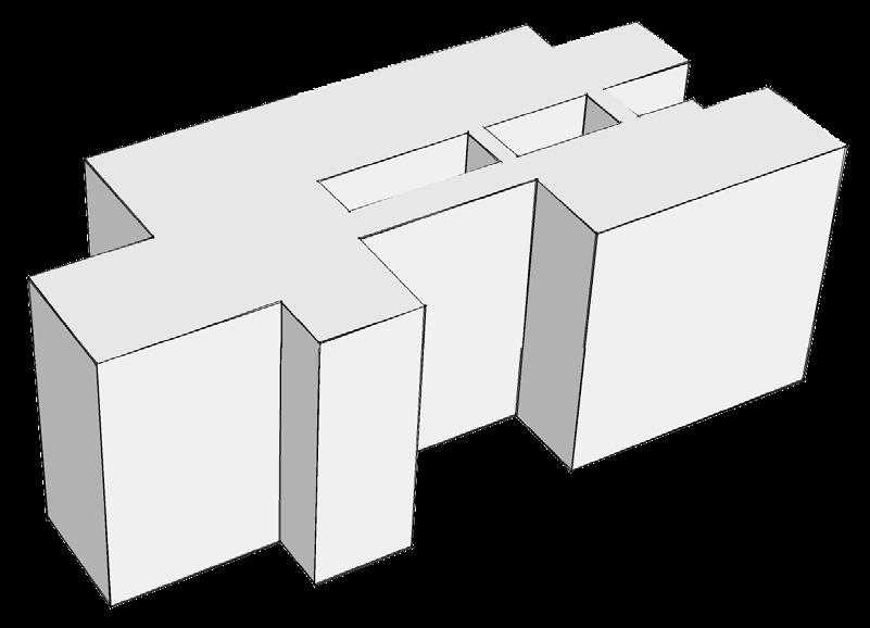
The longer sides of the building are made to face North - South direction. It helps in allowing air and maximum amount of light inside the habitable spaces.


Each lecture hall and studio unit has its longer side facing North - South orientation. The strategy helps in positioning maximum number of openings along North & South.
The surface area on the East and West facade are reduced by positioning the shorter side of the units on those orientation. Further, to cut off the radiation entering into the habitable spaces, non - habitable spaces such as toilets are located on those orientations.
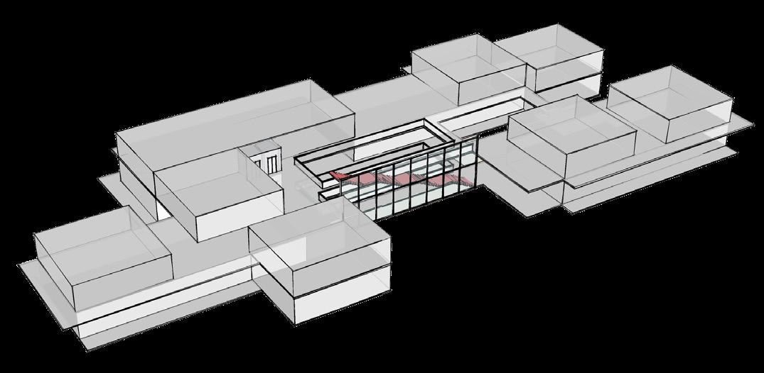
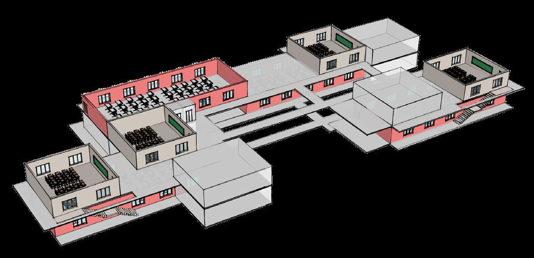
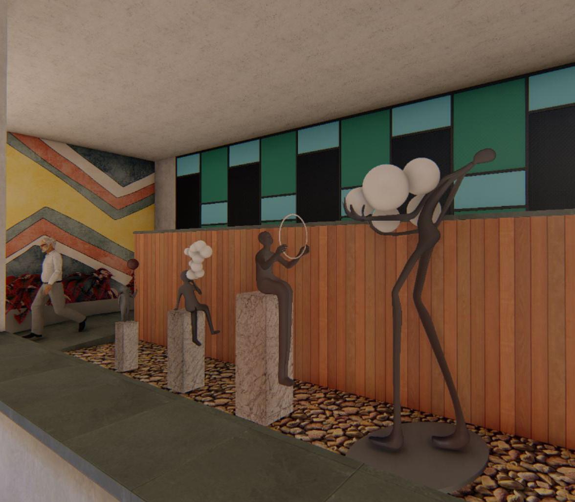
Positioning of courtyard in the central of the building, thereby creating void in a solid mass - Enhances visual quality, allows hot air to pass through the opening at the top, allows air circulation, allows daylight to enter into the building, vegetation in the courtyard enhances the microclimate, acts as an interactive space, acts as a place for displaying student works such as sculptures
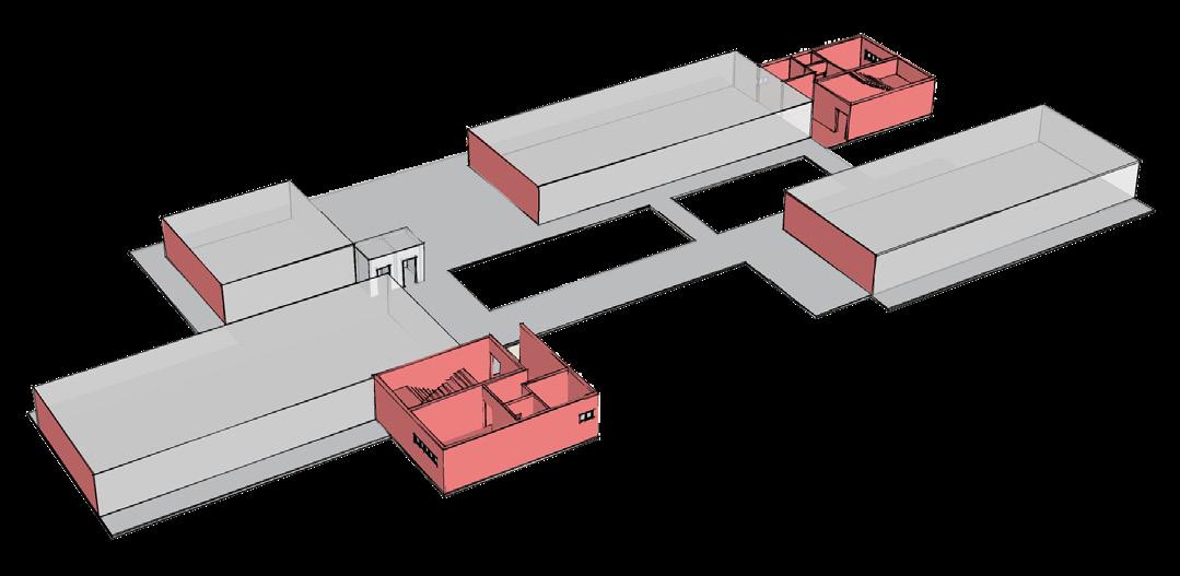
Each studio unit has its lecture hall in a close proximity - either connected through a private staircase from studio unit to lecture hall or located adjacent to it.
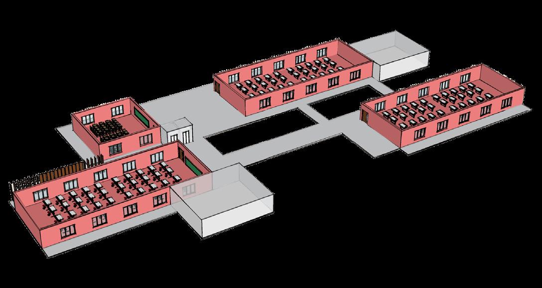
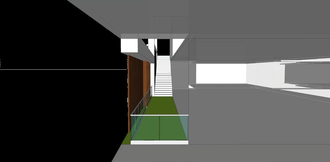
The circulation corridor is located adjacent to the central courtyard at each floor. Therefore, the area receives good amount of daylight & ventilation throughout the day. The corridor also gets an aesthetical view of the courtyard that is provided on the ground floor.
The breakout spaces are present at each floor - acting as a multi functional spaces such as jury space, gathering space, small event space, seating or relaxation zone, workshop or modelling area.
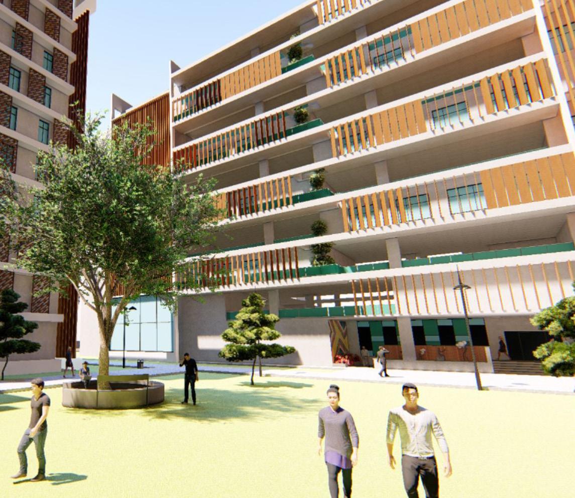
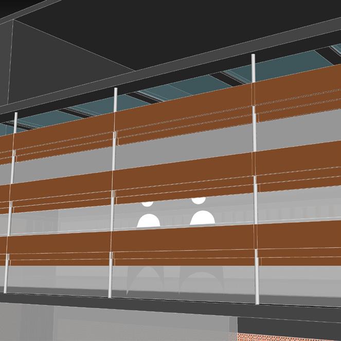
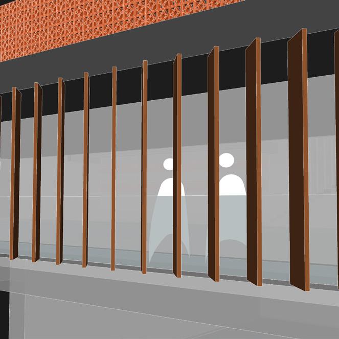
The North & South facade has a double skin layer & the space between acts as transition zone for the exterior & interior space. This transition zone has been treated as a private breakout space for each studio or lecture hall.
The grand stair has been positioned to the southern facade & it is made to receive good amount of daylight all throughout the day. The users get a good view of the exterior & its surroundings from the openings along the staircase.
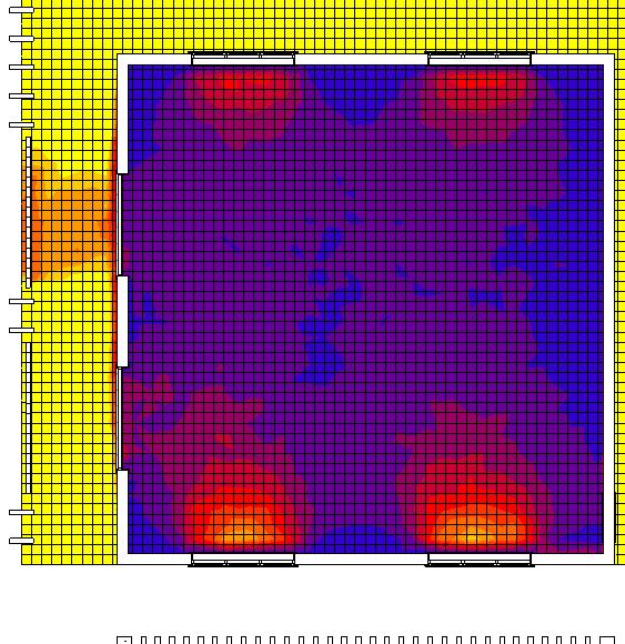
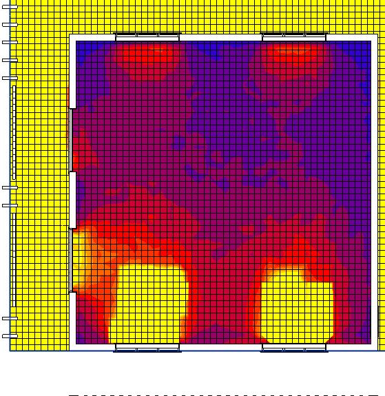
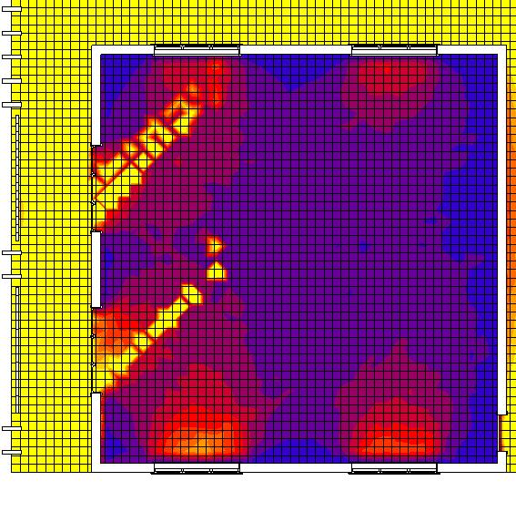
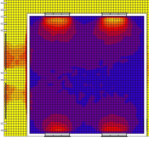
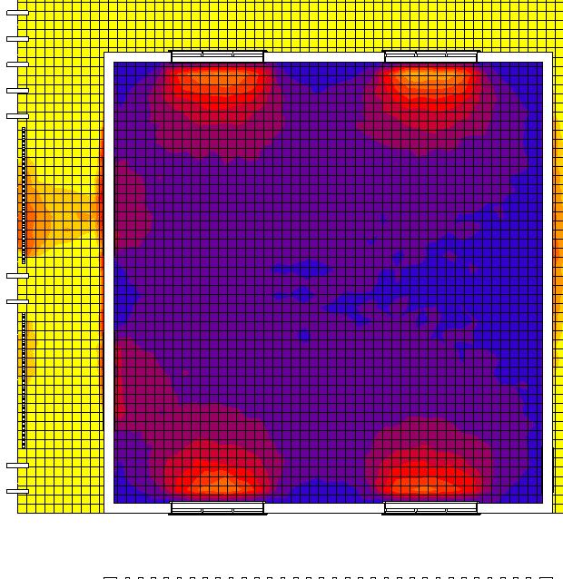
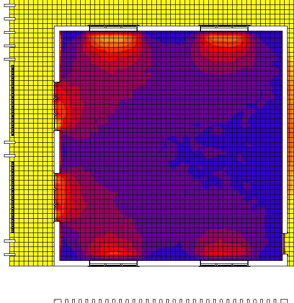
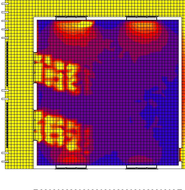
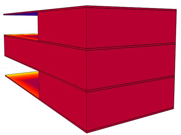
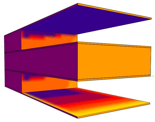
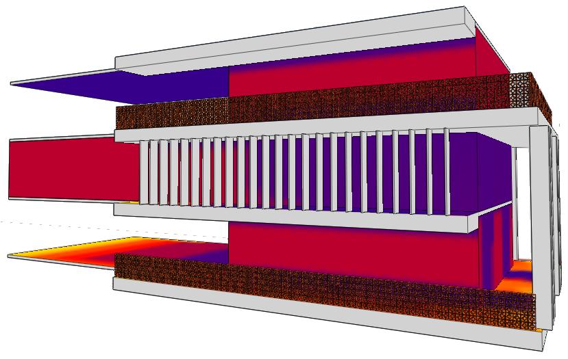
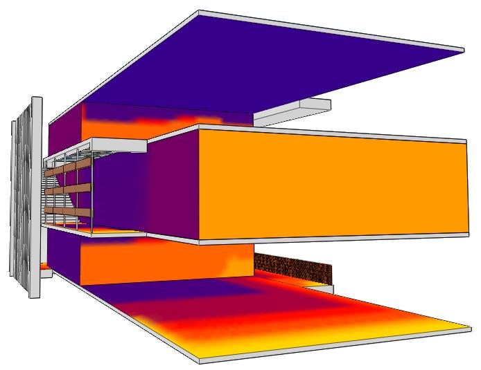
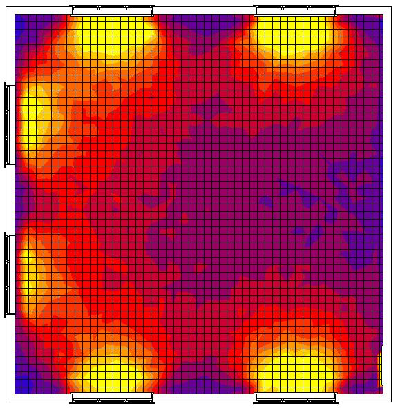
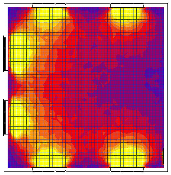
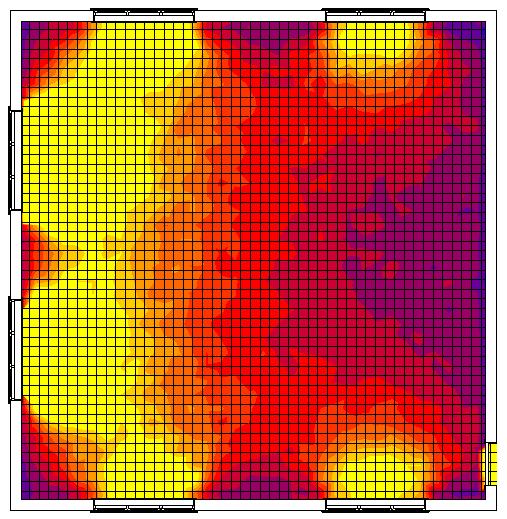
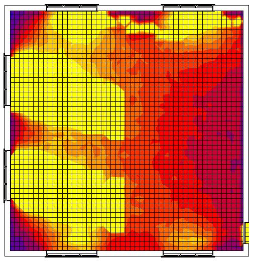
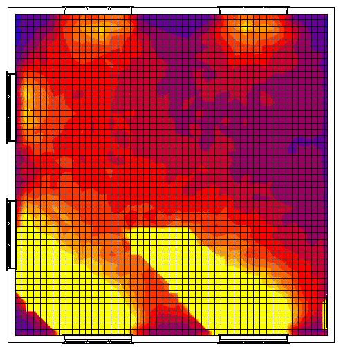
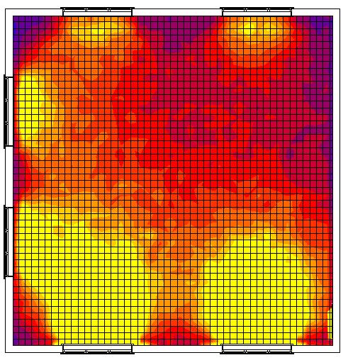
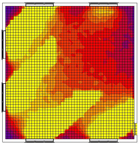
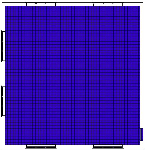

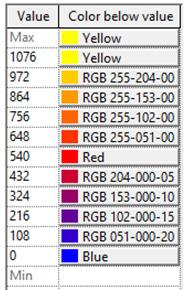
Option 1
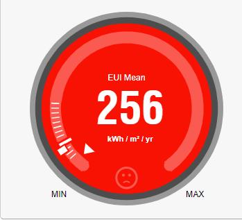
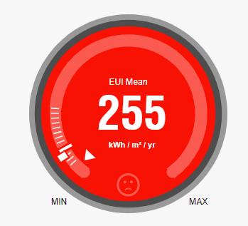
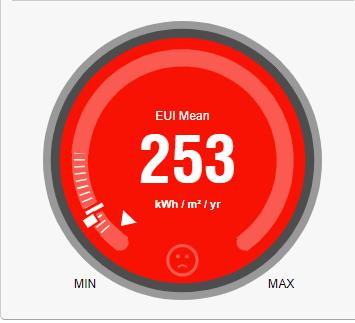
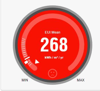
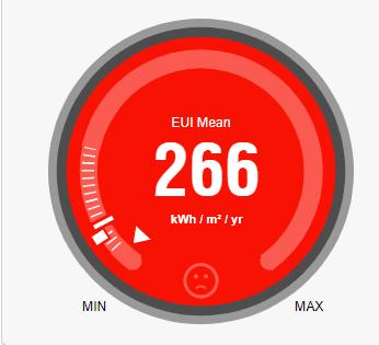
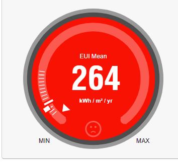
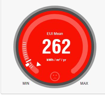
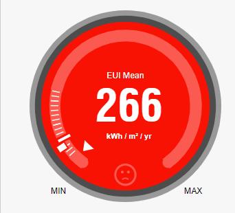
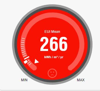
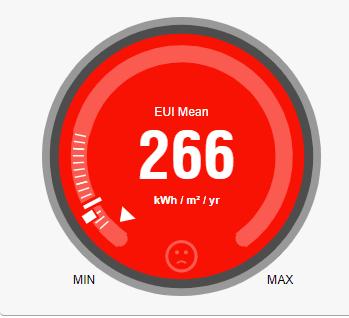
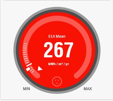
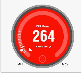
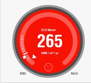
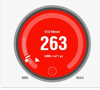
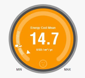
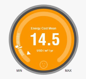
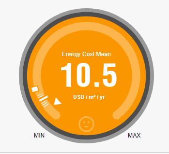
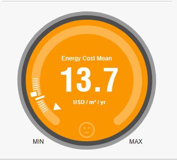
Standard wall construction - C - U-Value - 0.3967 W/m2 °K
Option 2
Brick, fiber insulation, light-weight concrete, dense plasterU-Value - 0.30 W/m2°K
Option 3
R-20 8 in CMU wall - U-Value - 0.2615 W/m2 °K
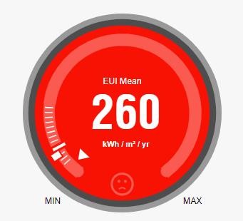

Option 4
4 inch insulation with 8 inch clay tile - U-Value - 0.22 W/m2 °K
02 ROOF CONSTRUCTION
Option 1
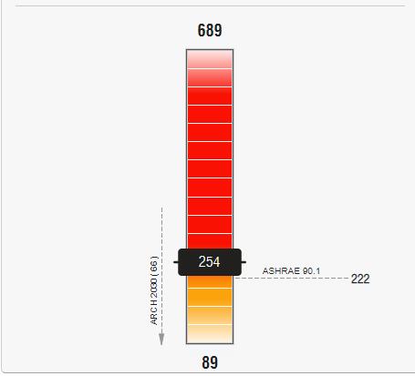
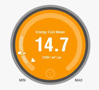
Flat roof - C - U-Value - 0.3183 W/m2 °K
Option 2
Membrane, sheathing, R-15 insulation, 6 inch light concreteU-Value - 0.296 W/m2°K
Option 3
Waterproof covering, polyurethane, screed, concrete, plasterU-Value - 0.22 W/m2 °K
Option 4
Waterproof covering, polyurethane, screed, concrete, plasterU-Value - 0.12 W/m2 °K
03 WINDOW - WALL RATIO
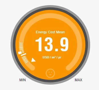
Option 1 - WWR - 40% ; Option 2 - WWR - 30%
Option 3 - WWR - 15% ; Option 4 - WWR - 0%
04 GLAZING SYSTEM
Option 1
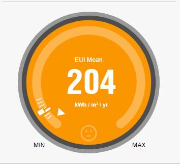
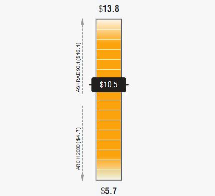
Double glazing - domestic SC - 0.3; U-2.8567 W/m2 °K; SHGC0.29
Option 2
Low - E triple glazing, SC - 0.2; U-Value - 1.4554 W/m2 °K; SHGC - 0.26
Option 3
Reflective double glazing - 1/4 inch thick - 20% titanium on clear glas; U-Value - 1.9873 W/m2 °K; SHGC - 0.21
Option 4
Reflective double glazing - 1/4 inch thick - 14% stainless steel on green glass; U-Value - 1.9873 W/m2 °K; SHGC - 0.16
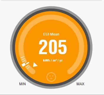
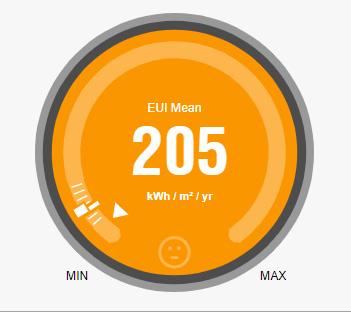
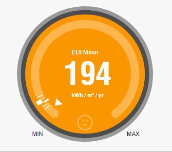
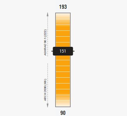
02 ROOF CONSTRUCTION 03 WINDOW -WALL RATIO 04 GLAZING SYSTEM
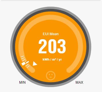
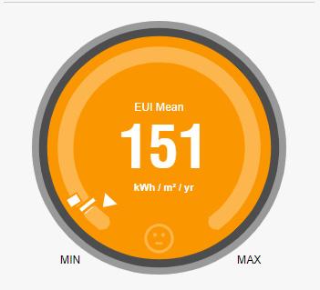
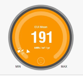
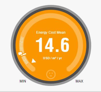
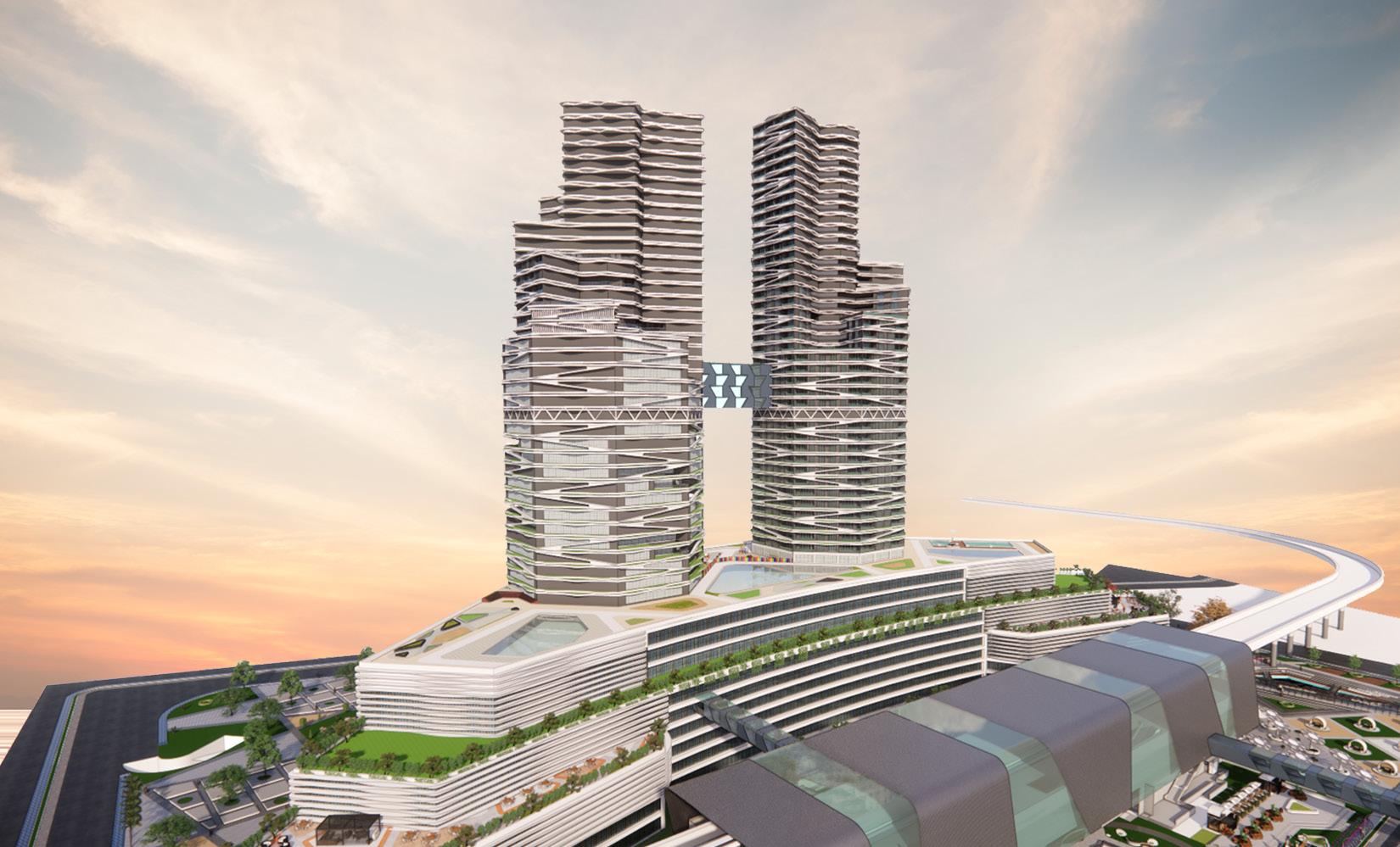
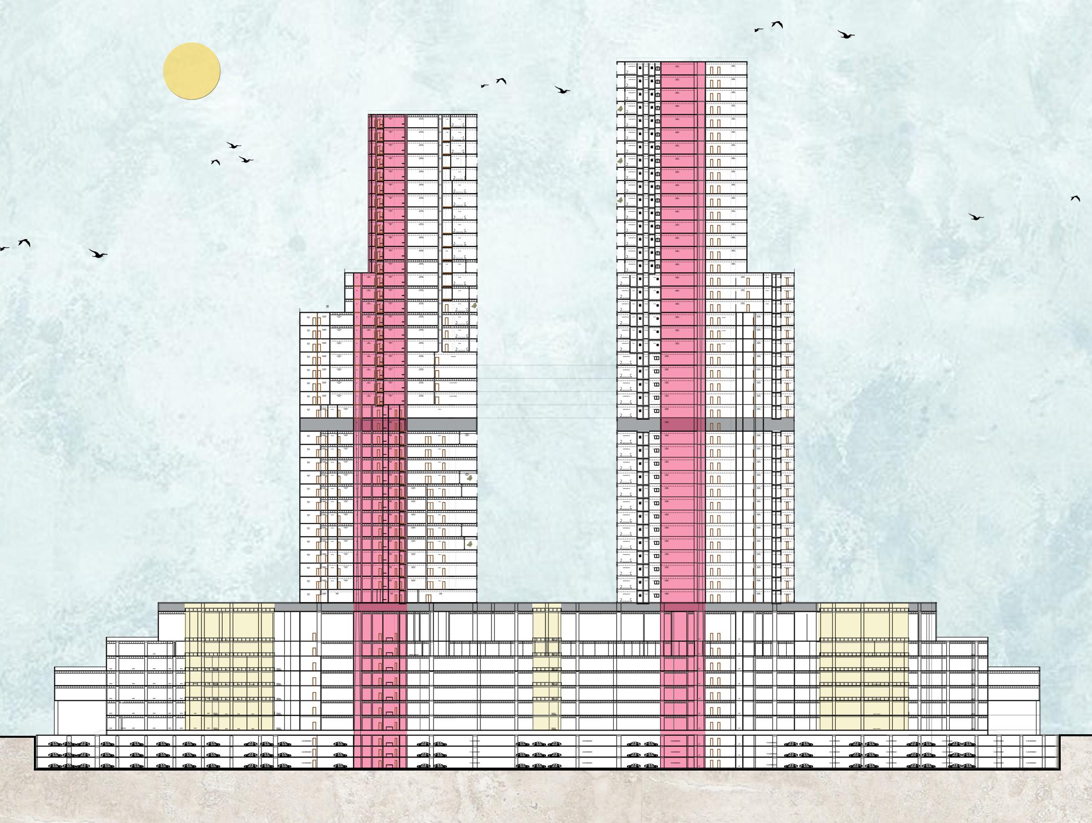
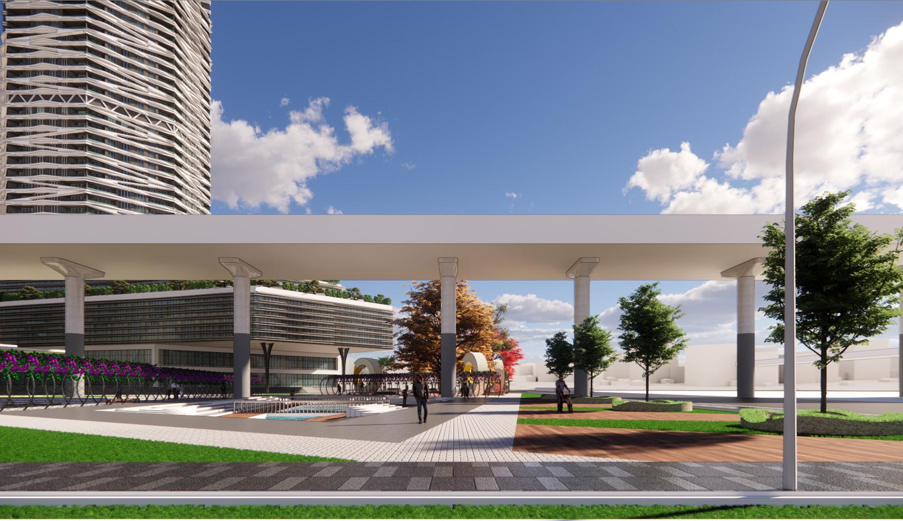
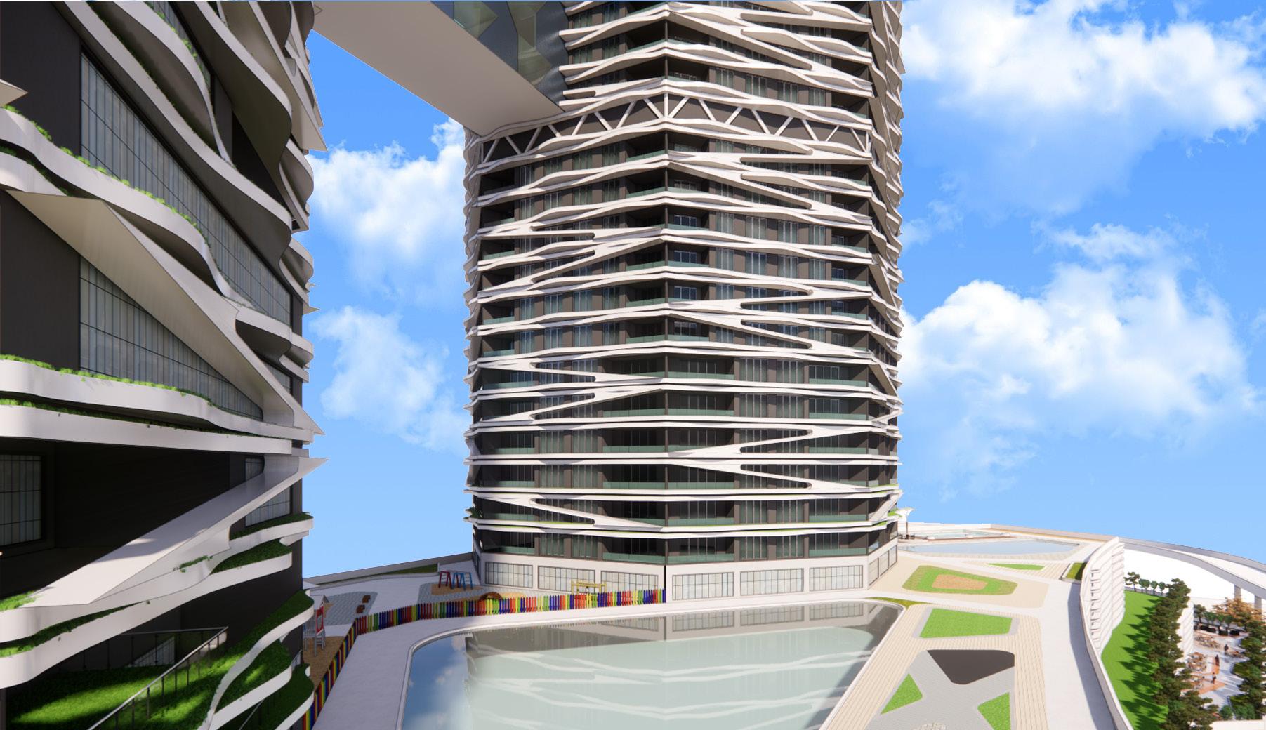
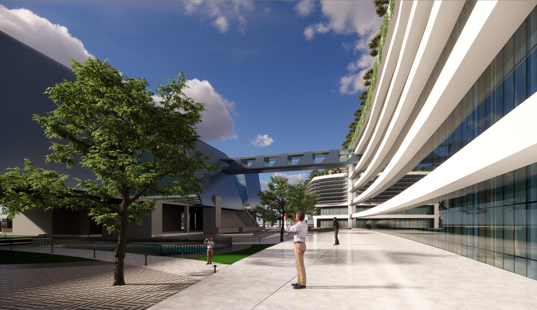
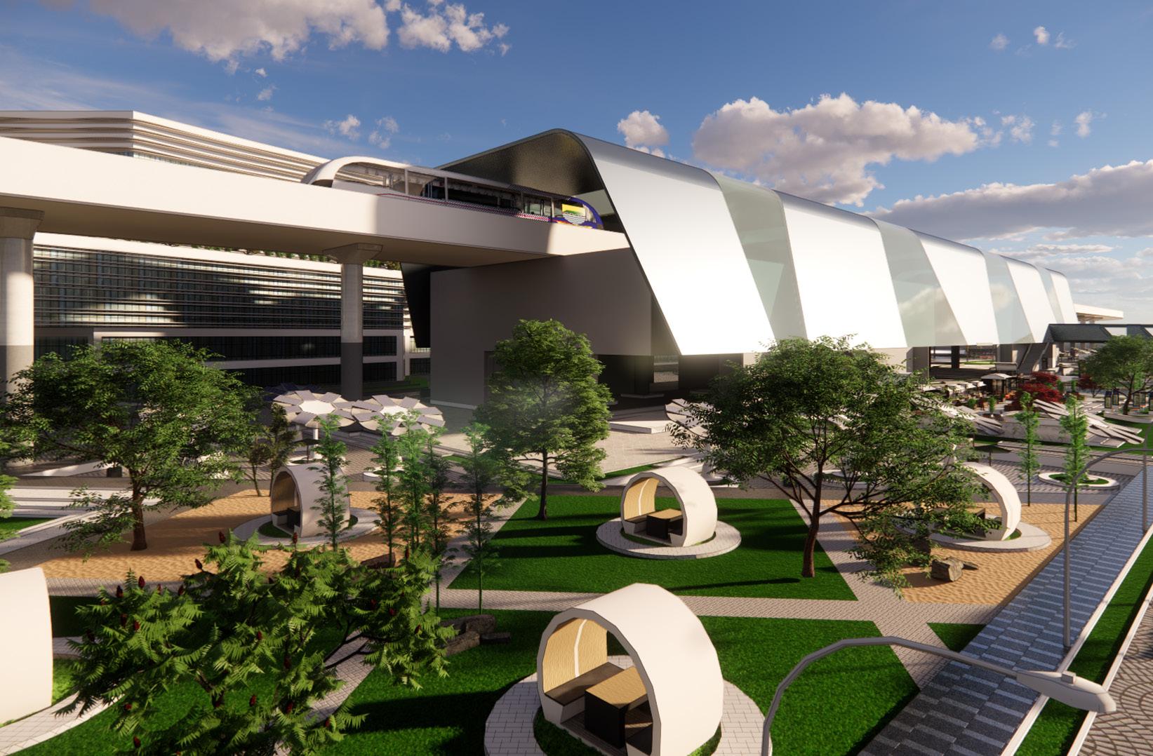
Transit Oriented Development is the exciting fast growing trend in creating vibrant, livable, sustainable communities. Also known as TOD, it’s the creation of compact, walkable, pedestrian-oriented, mixed-use communities centered around high quality train systems. This makes it possible to live a lower-stress life without complete dependence on a car for mobility and survival.
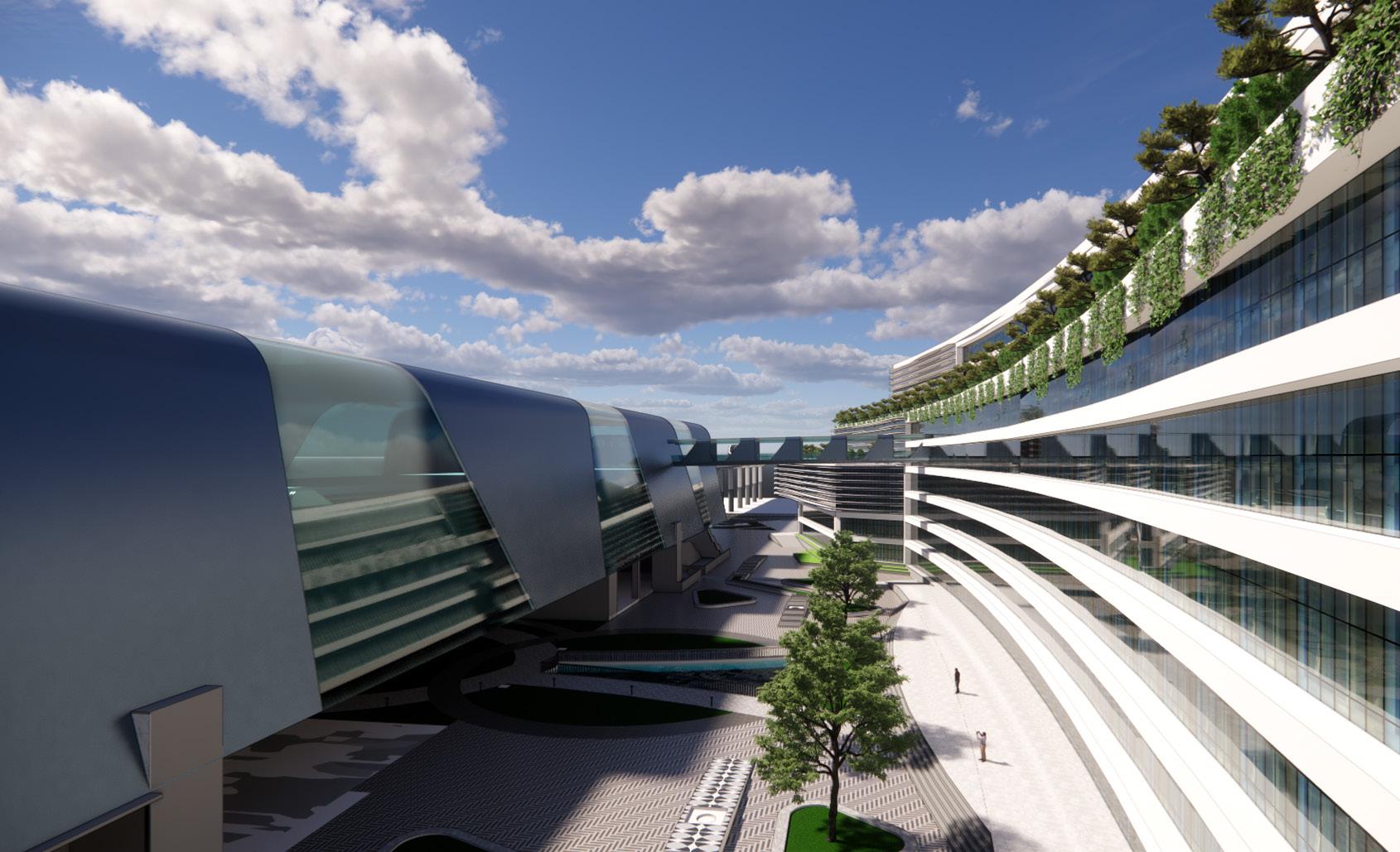
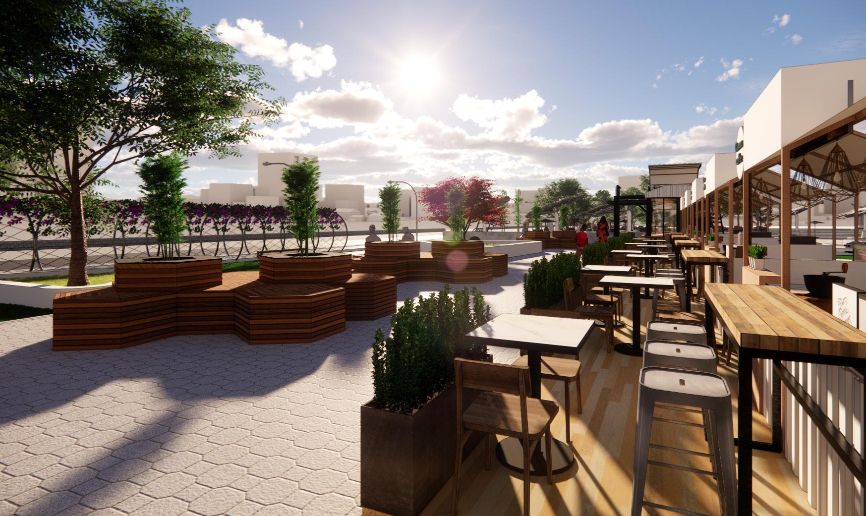
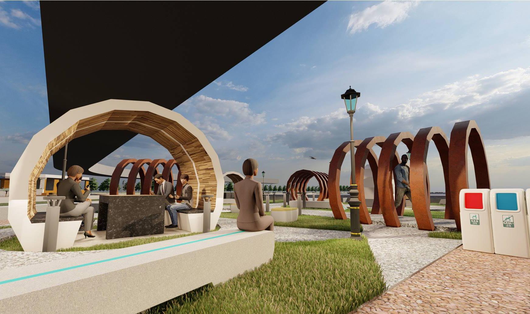
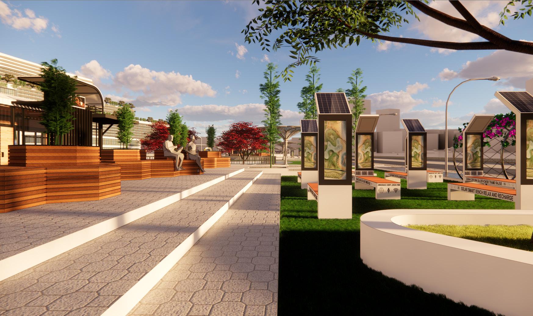
The aim of this project is to develop a Transit Oriented Development which supports a chain of seamless connectivity from the sub Urban to the Chennai city with sustainable mobility options which focuses on last mile connectivity. Also, to develop a Multi modal transit station that will encourage sustainable mobility, imageability, maintainability, walkability by connecting different land uses leading to a harmonious environment.
Site location - Chennai
Site area - 28 acres (1,13,311.96 SqM)
Typology - Mixed use
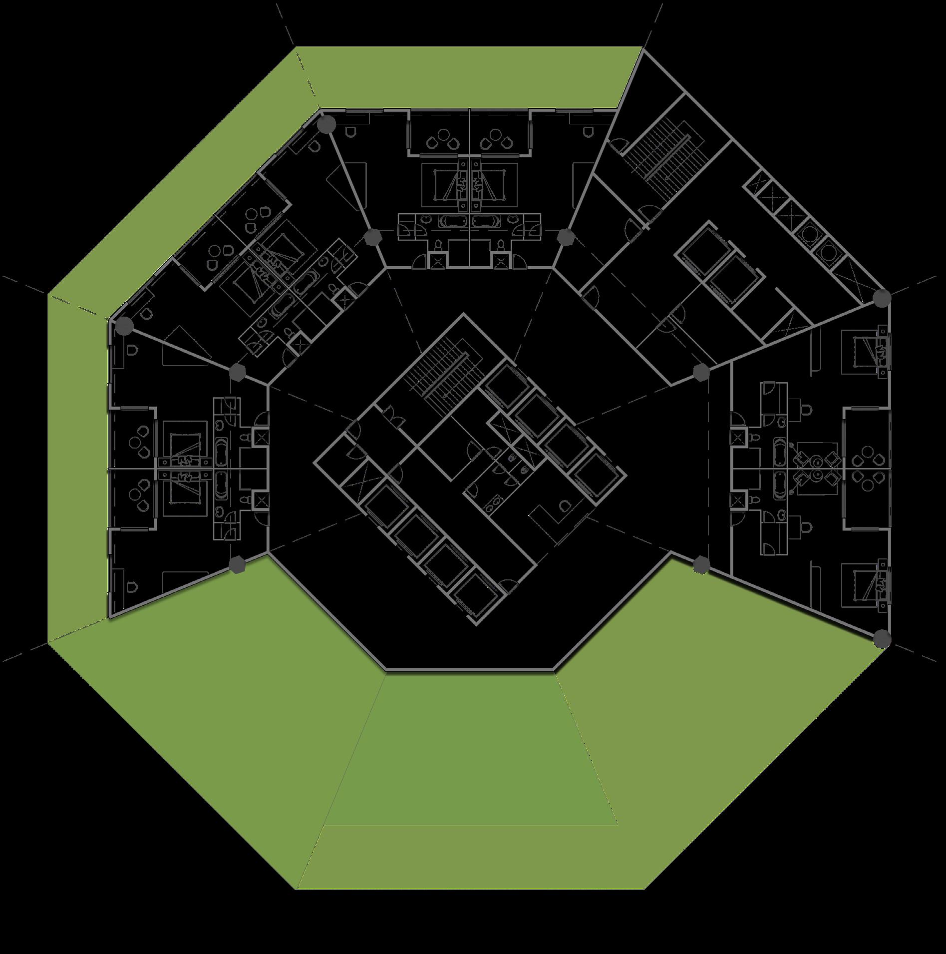
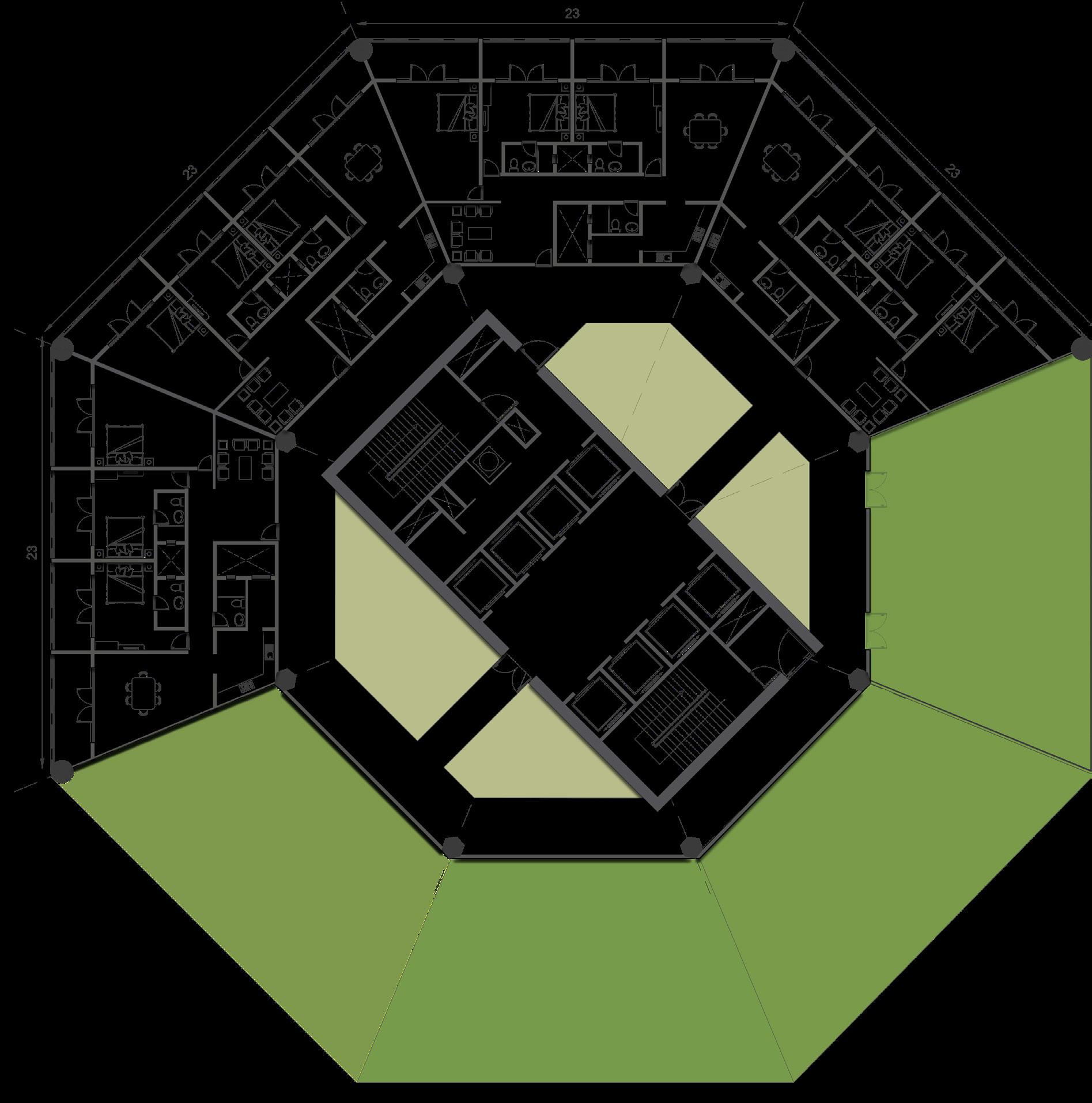
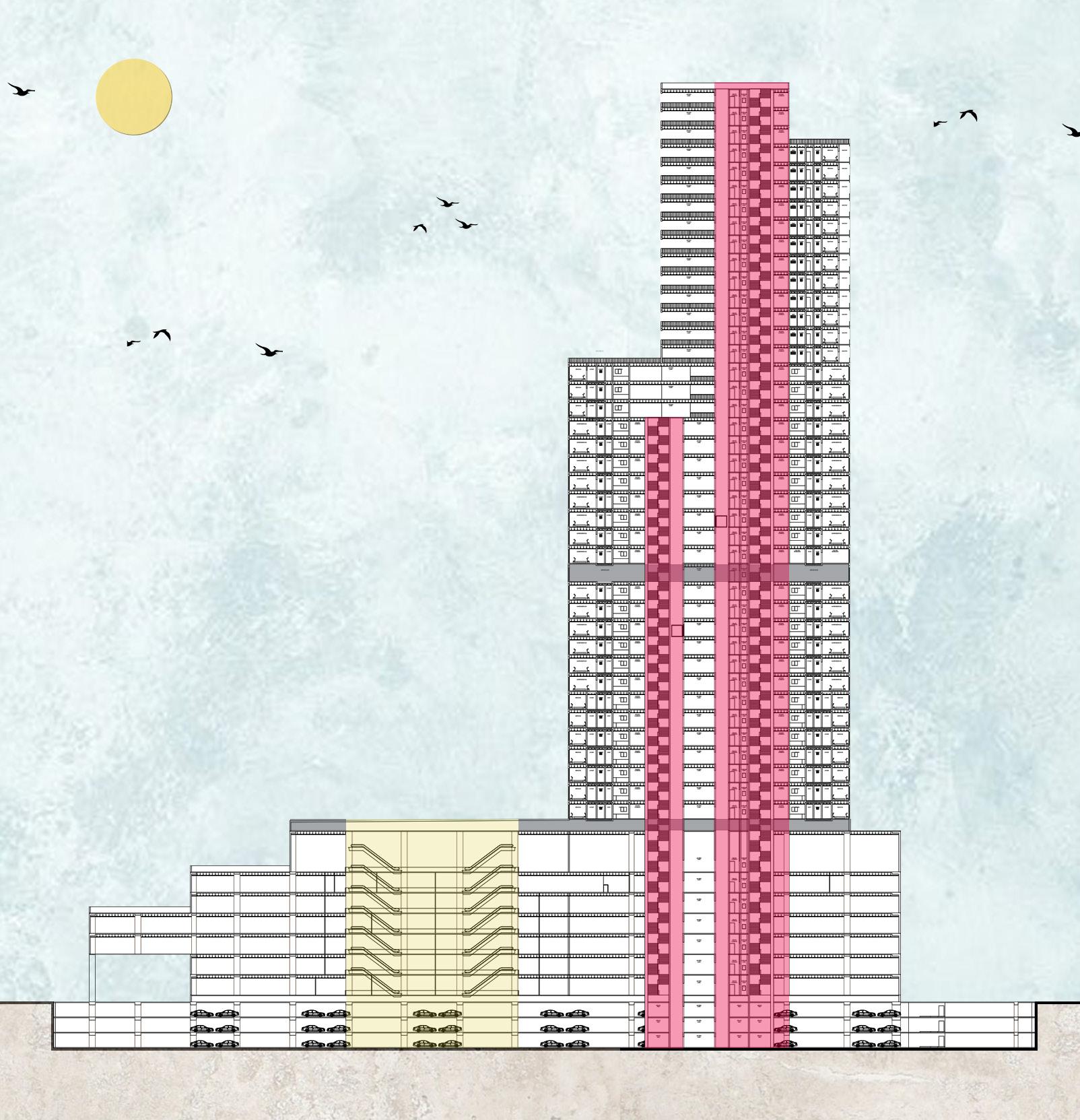
Program - Metro station, shopping mall, residential tower, office tower, hotel, etc
AutoCAD, SketchUp, Photoshop, Lumion
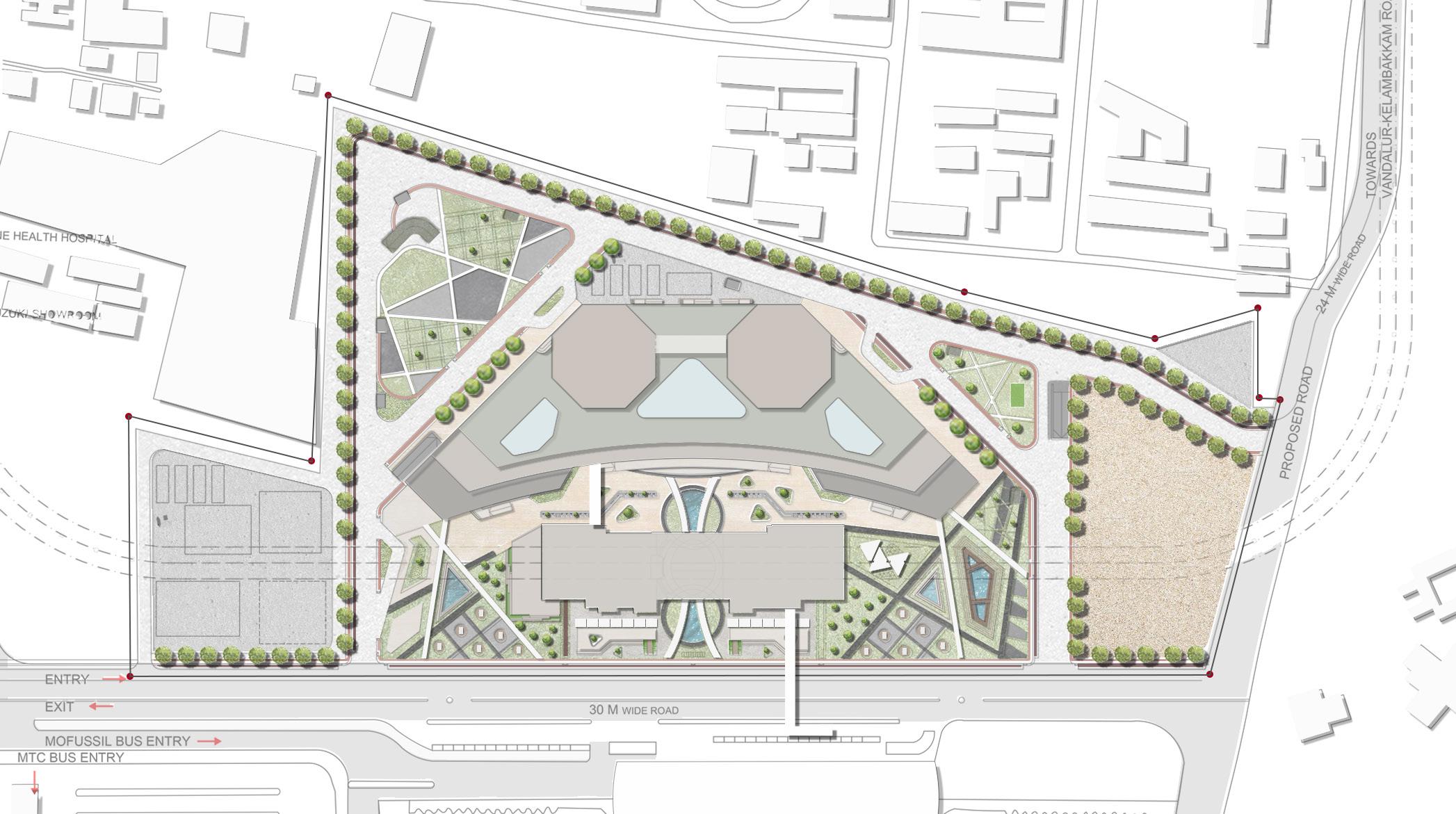

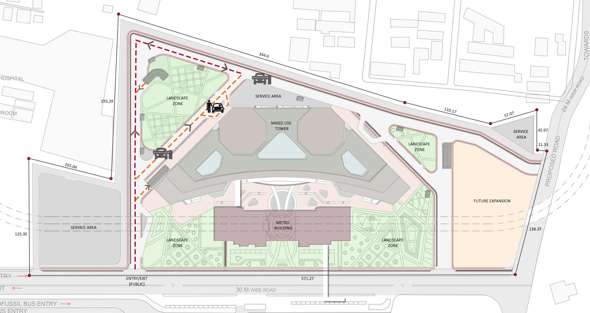
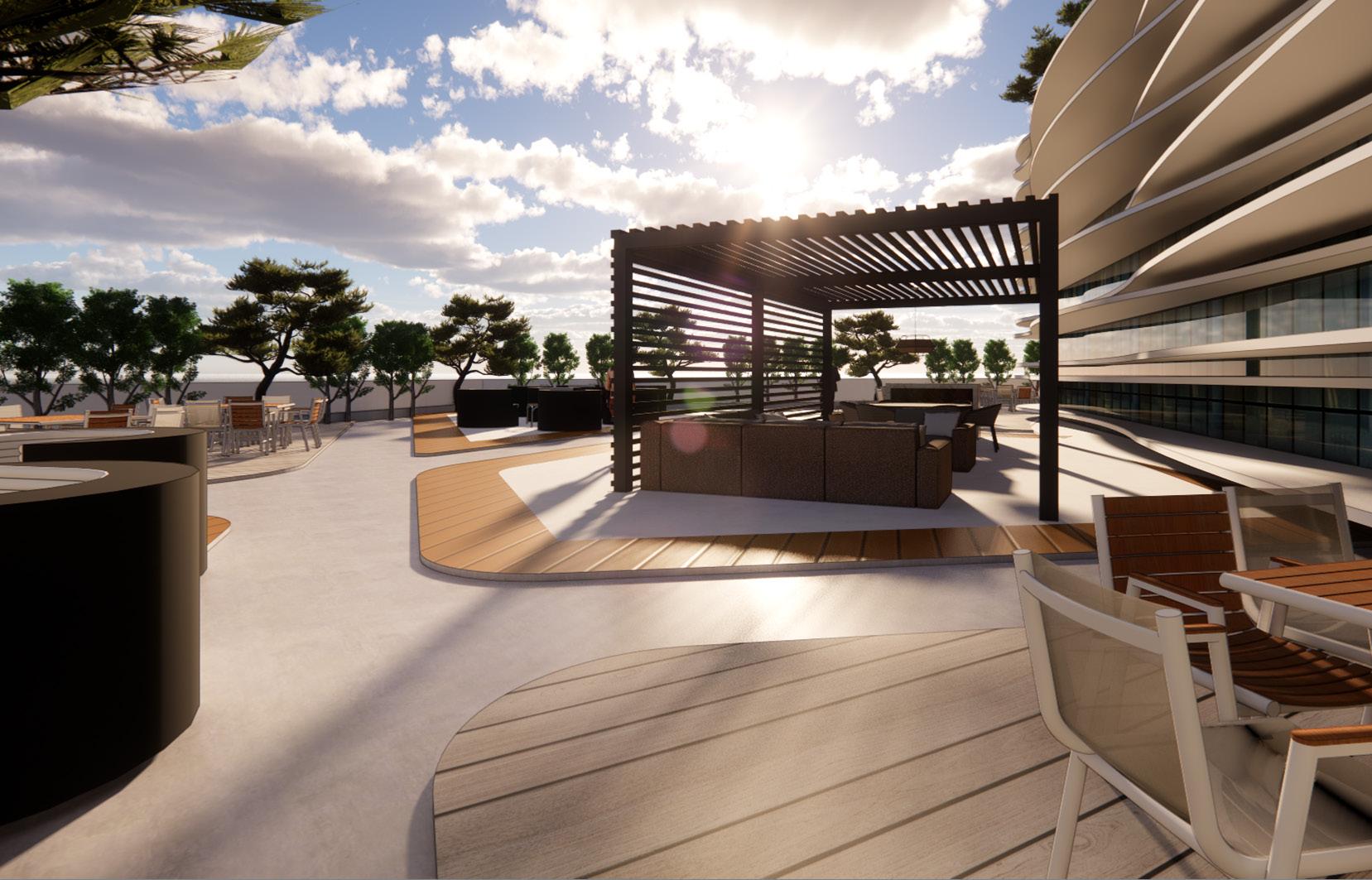
Exclusive drop off lane for public vehicles in the southern side is provided , thus it prevents from congestion with the other users. Security check point is provided to restrict the public movement to the office zone.Pedestrian connections are provided through out the site encouraging non-motorized transportation to the mall and between the mall and other spaces.Sufficient pick up/ dropoff points for each use, thereby discouraging congestion and encouraging seamless motorized and non-motorized movement.
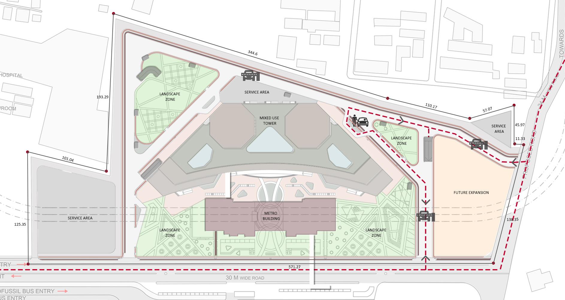
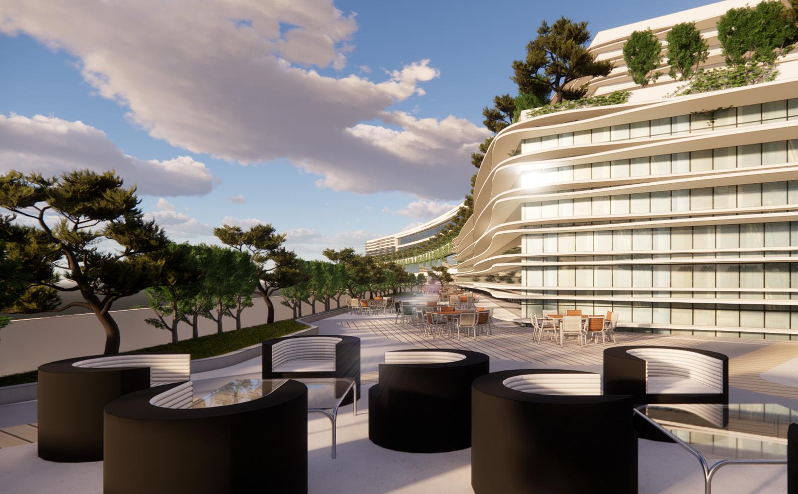
Exclusive drop off lane for hotel and office users has been provided. Security check point is provided to restrict the entry of mall users to office and hotel and it also restricts the entry to residential zone. Traffic calming is ensured. Seamless movement with less chaos and congestion is achieved by promoting non - motorised transportations. Roads are planned in such a way that no much hindrance is experienced by the pedestrians and bicycle users.
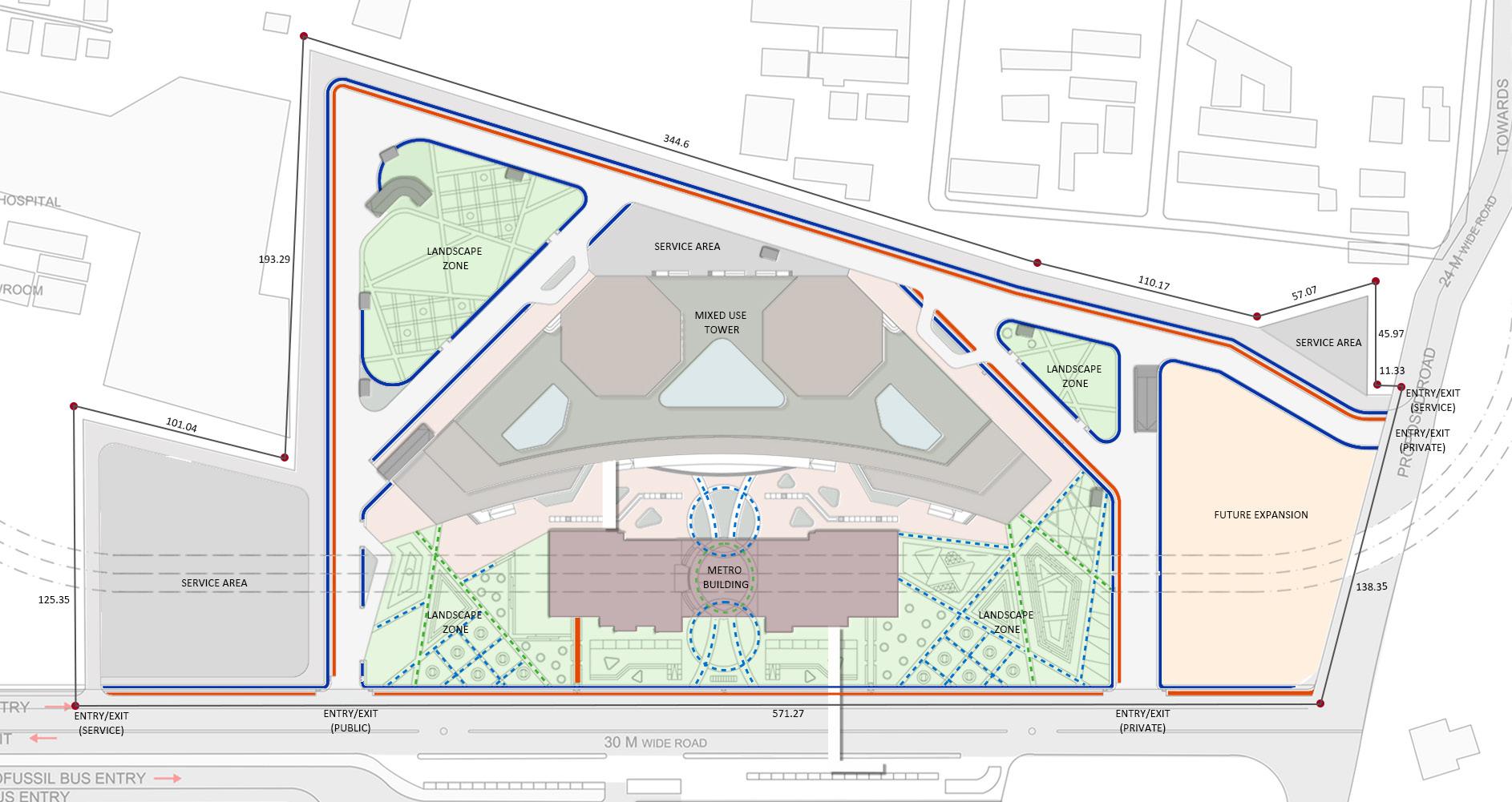
Separate entry/exit for residential users is provided by which public vehicle movement has been restricted. Security check point ensure the privacy and restricted movement into the residential zone. Proper segregation with less intervention from other users of the site is ensured. Exclusive entry/ exit from both GST and kolapakkam road.
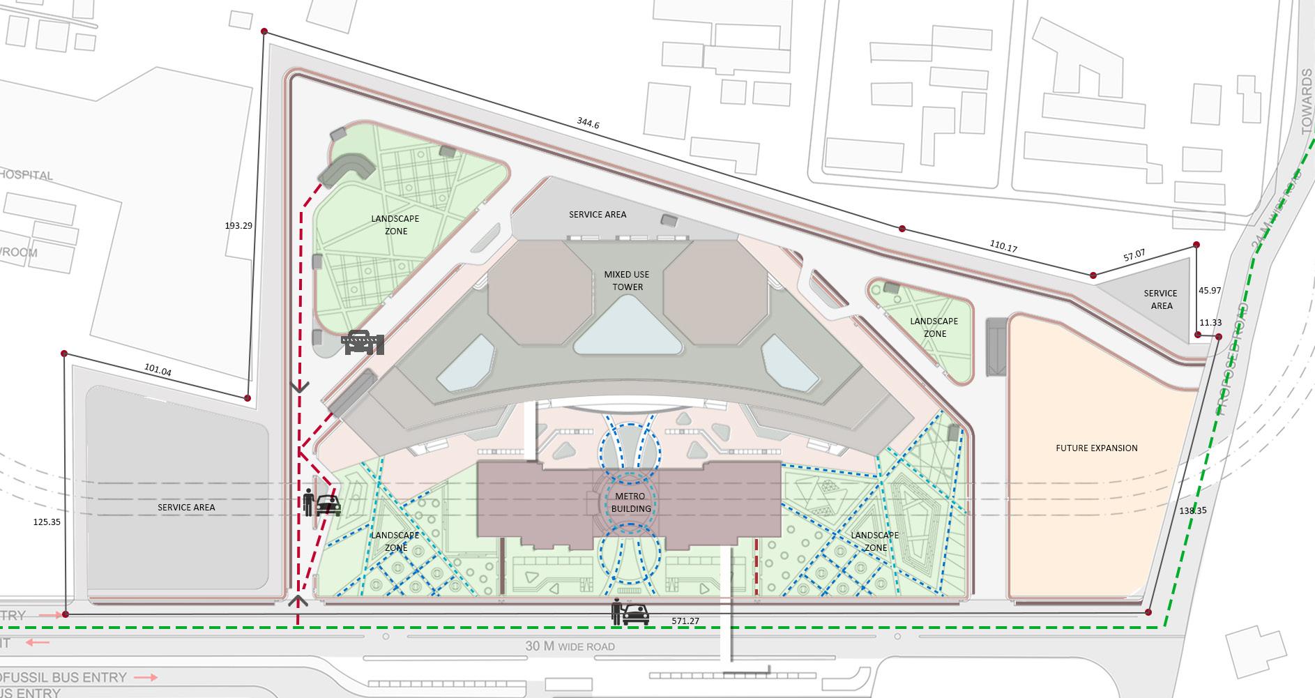
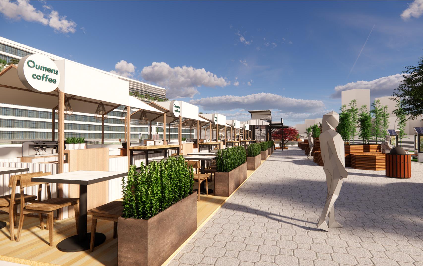
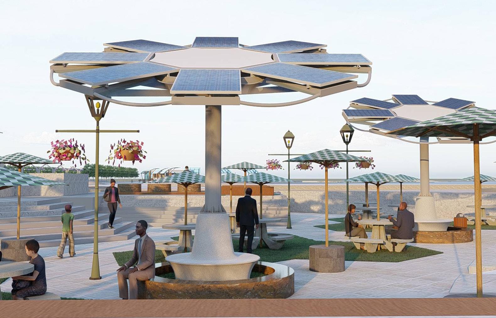
The site is surrounded by uninterrupted pedestrian and cycle movement. Thus it makes a pedestrian friendly neighbourhood. Both open and shaded pathways are provided to promote walkability inside the site. Ramps are provided, thereby, making it an universal design. Street furnitures such as bollards, lamp post, seating area along the pathway, trees are taken into account during the design stage.
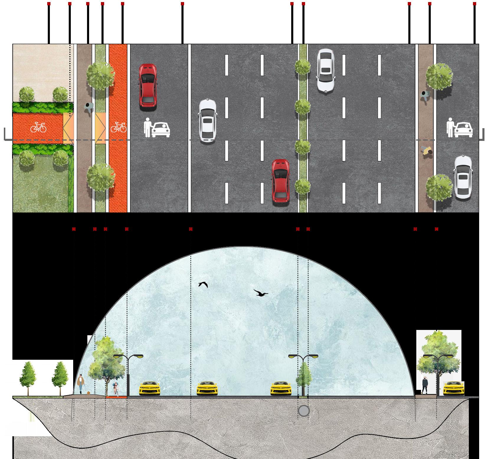
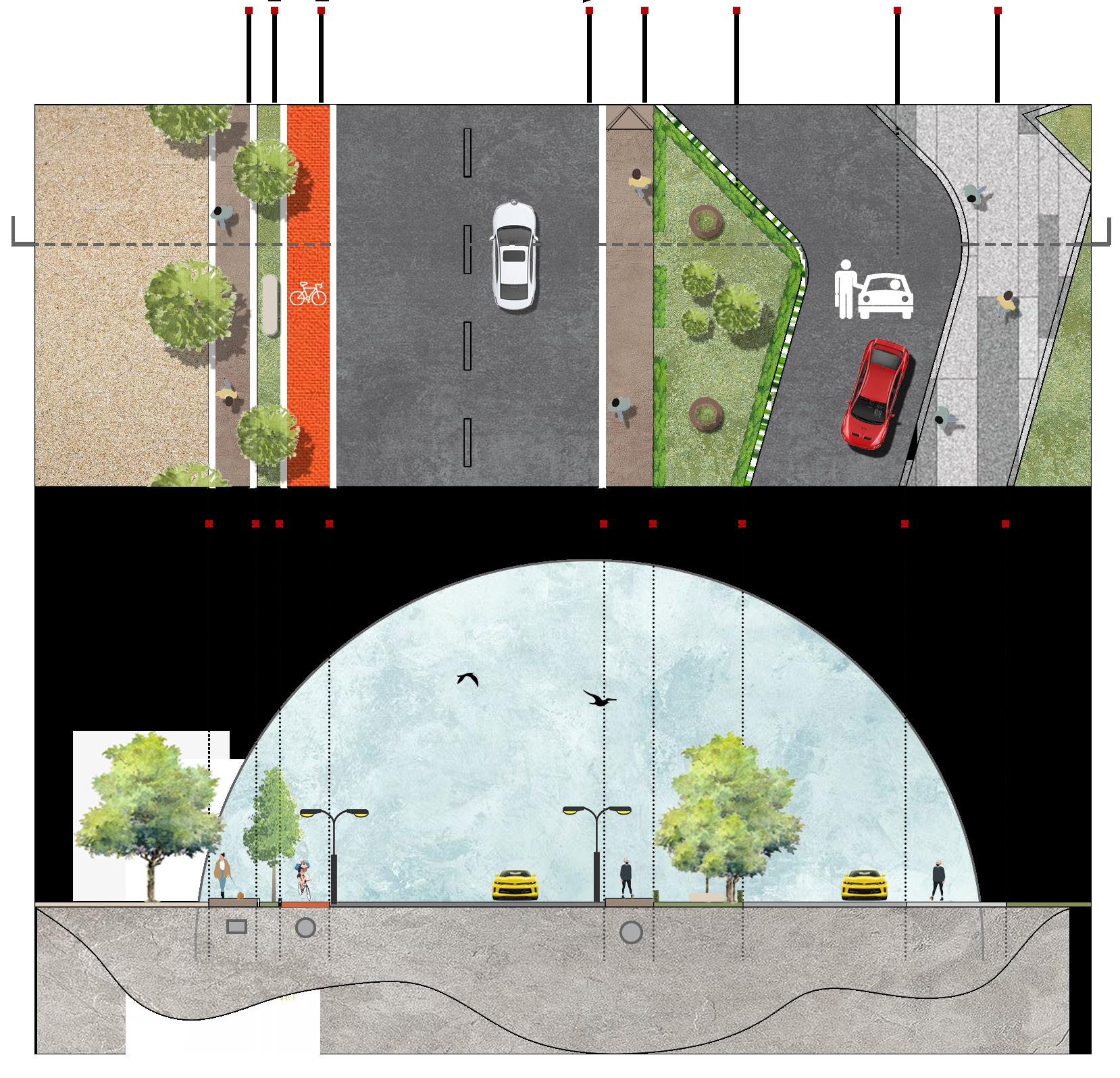


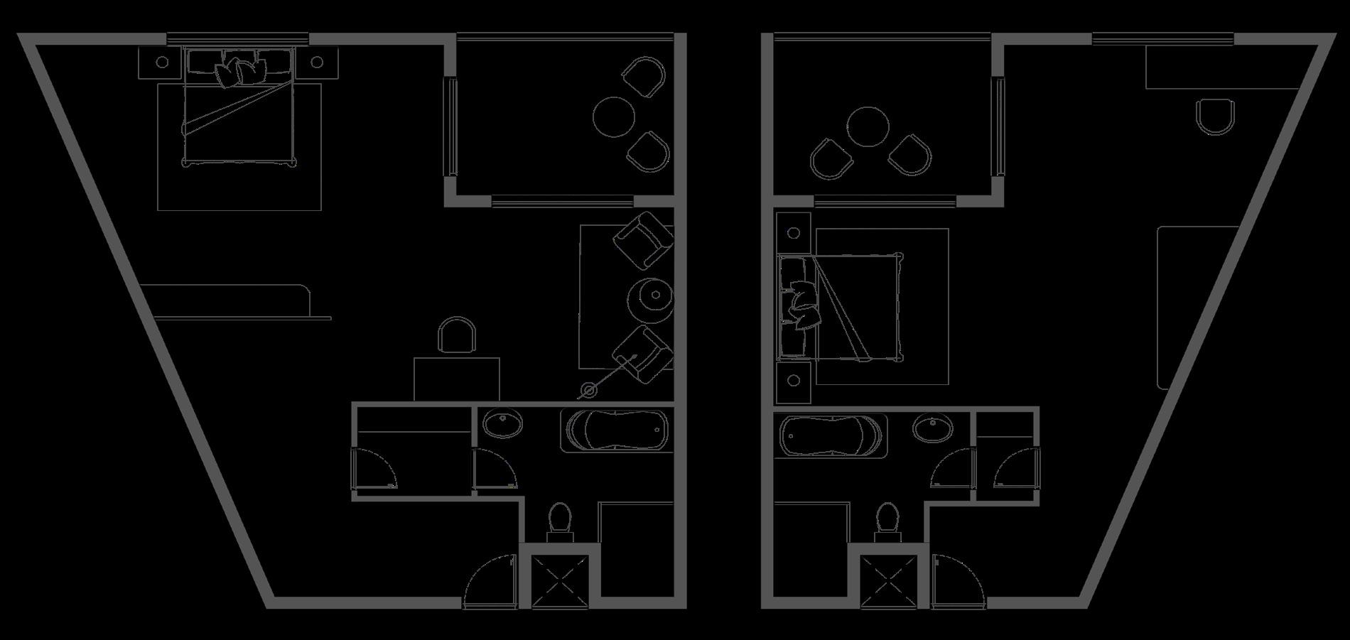
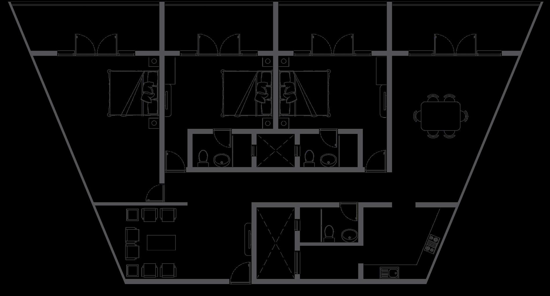
LEGEND (RESIDENCE) LEGEND (HOTEL)

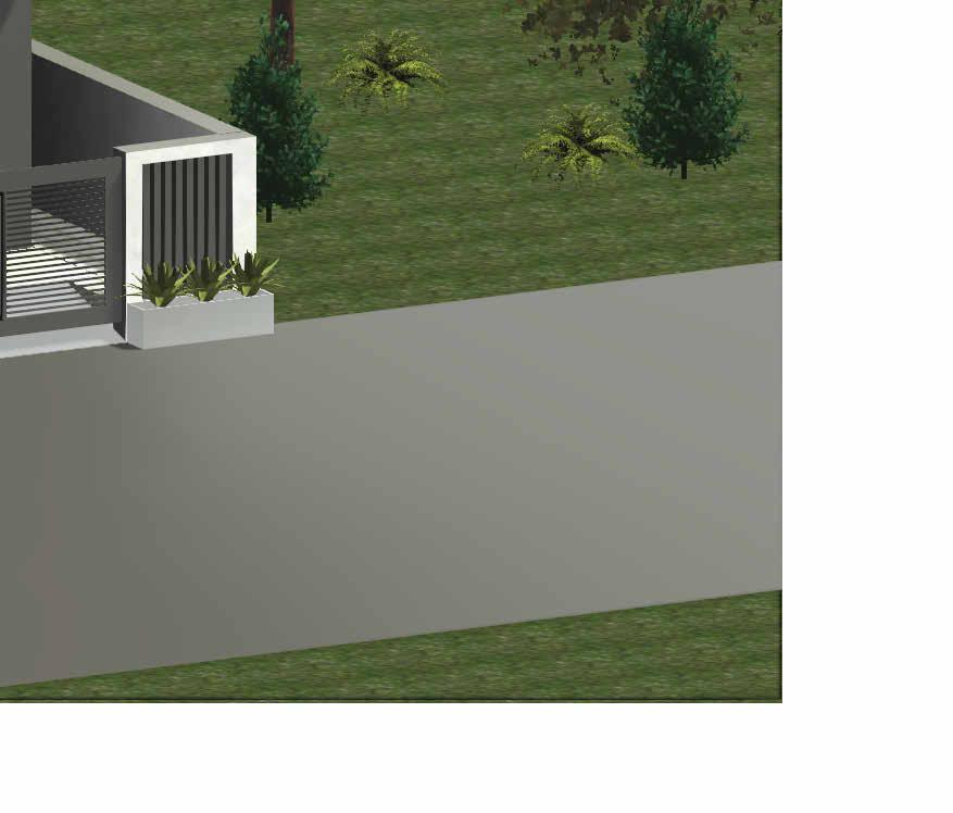
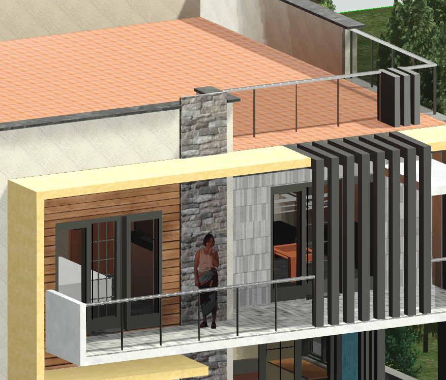
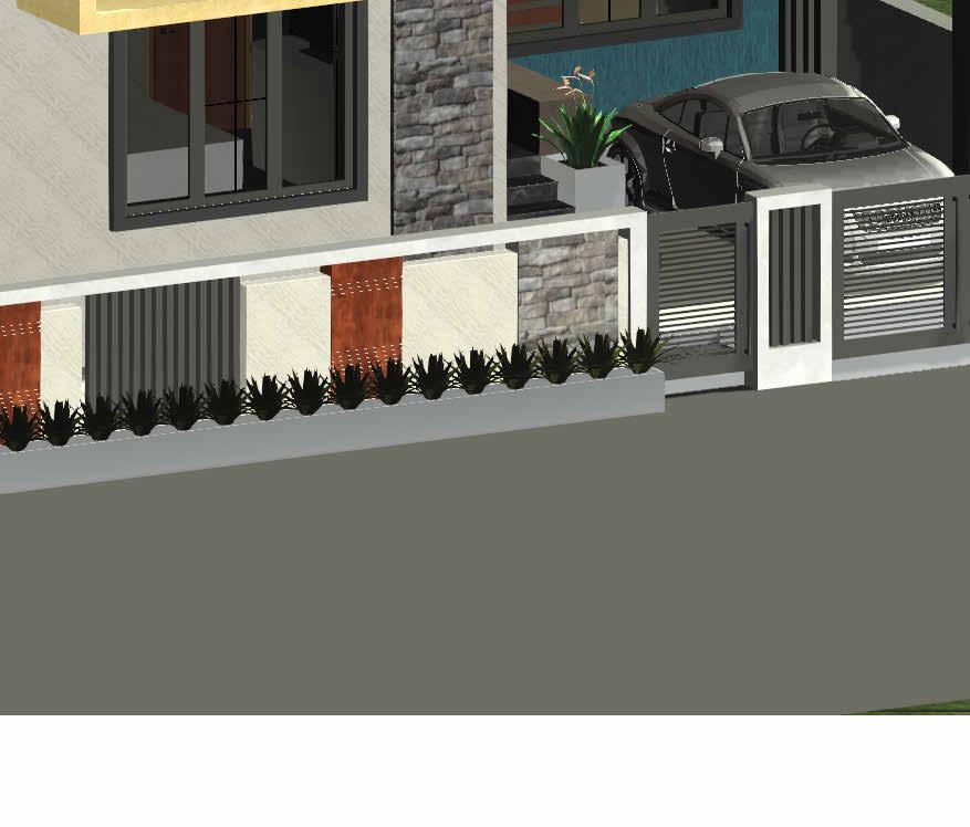
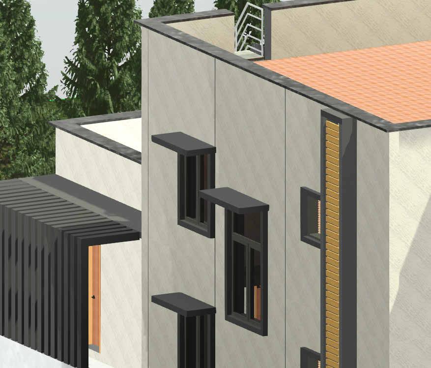
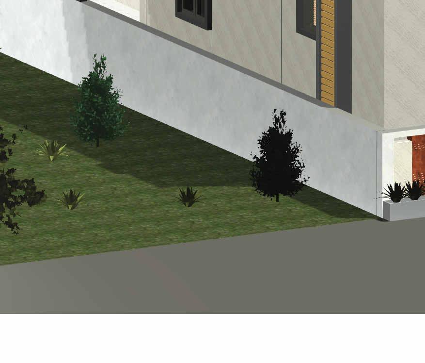
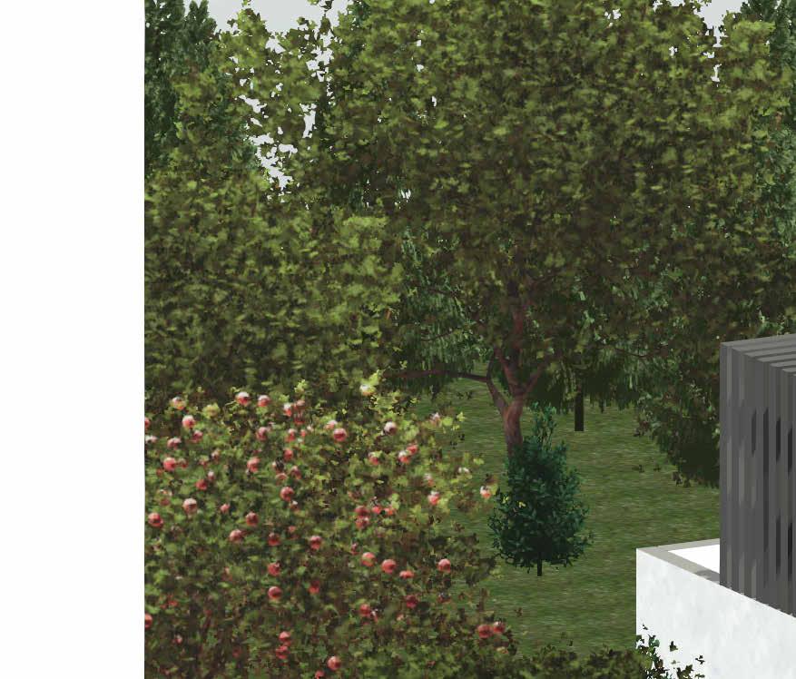
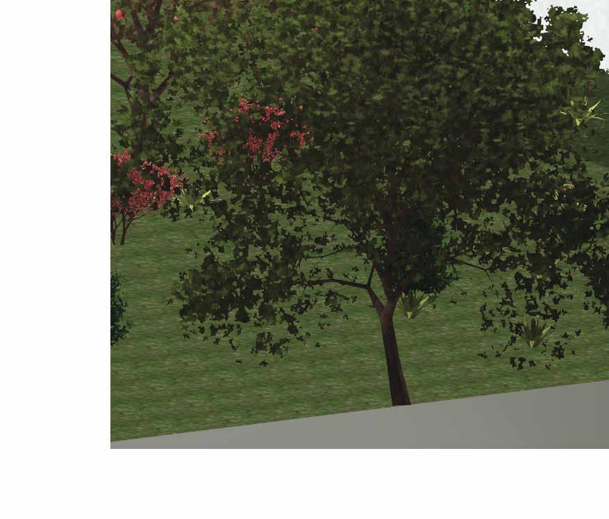
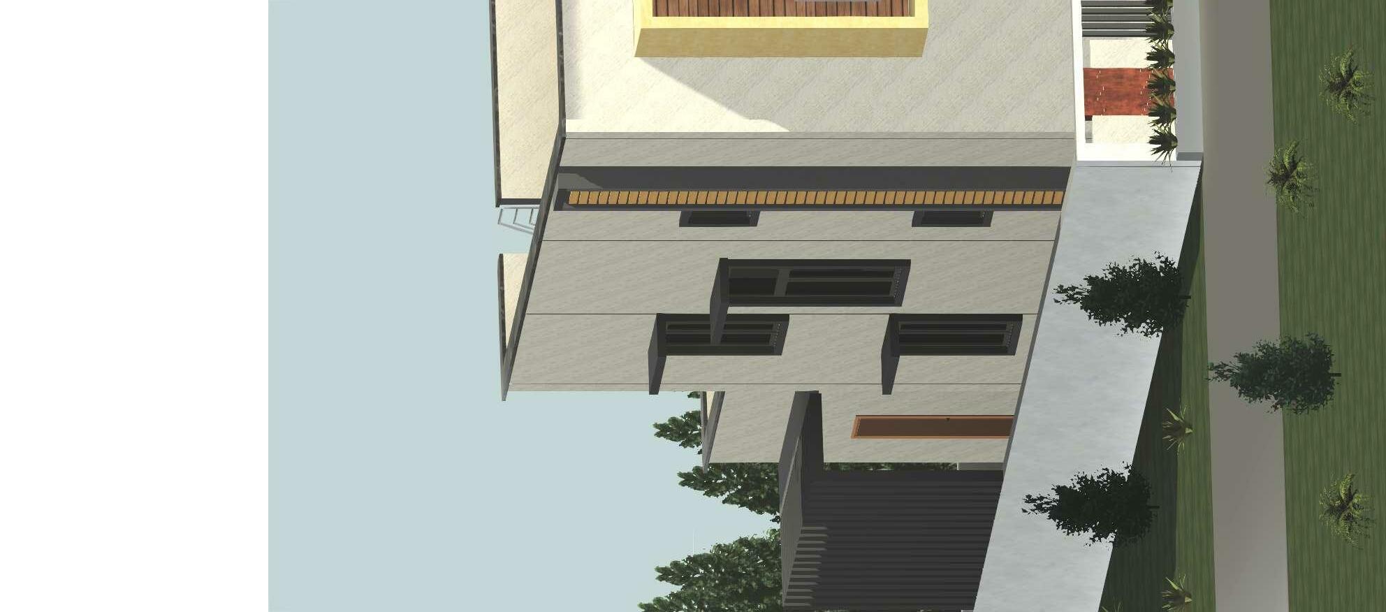
This is a residential project, owned by Mr.Selva Kumar and it is located in Needamangalam, Thiruvarur. The aim of this project is to design a residence for a family of 6 people with 3 bedrooms, one formal and one informal living area, kitchen and dining area. The main objective is to create an airy environment with an ample amount of day light in the interior of the building, thereby connecting interior to the exterior through a transition space such as balcony and terrace.
Site location - Needamangalam, Thiruvarur
Site area - 2400 SqFt
Typology - Residential
Program - Living area, Bedroom, Kitchen, Dining area
Revit
No.DescriptionDate 3/8" = 1'-0" GROUND FLOOR -FURNITURE PLAN 1
This document and its contents are the copyright of BRICKS & SPACE ARCHITECTS. Any party receiving this document does so in confidence and agrees that any of the information contained herein shall not be reproduced in whole or in part or disclosed to others without prior written consent of the architect.
BRICKS & SPACE ARCHITECTS Ar.Bharathi Ph : +019944344347 Email : bharathishanmuganathan1997 @gmail.com Address :
DATE DRAWN BY
10/29/22 Ar.Shilpa S
Ar.Bharathi Ground FloorFurniture Plan
SHEET NUMBER
SCALE (A1) REVISION NO
CHECKED BY NORTH
A102 00
PROJECT CLIENT DOCUMENT STATUS
NOTES 1.
APPROVED BY 3/8" = 1'0" Mr. Selva Kumar Residence Mr. Selva Kumar
DRAWING TITLE Working Drawing
Drawings to be read & not scaled. All dimensions are in feet and inches. 2.
All levels are given with respect to centre line of external road taken as 0.00. 3.
Please refer all R.C.C details in conjunction with Structural Drawing. 4.
Any discrepancy to be brought to the notice of the architect. 5.
Framing to be as per relevant architectural & structural drawings.
1 A106
1'10 1/2"
3'1 1/2"
9'7 1/2"
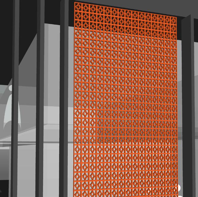
CNC Panel Shading Device Above 6" x 4" Powder Coated Steel Rectangular Hollow Box Section of 5mm Thickness 10'8 1/2" Shading Device
10'8 1/2" Shading Device 13'3 1/2" Shading Device
This document and its contents are the copyright of BRICKS & SPACE ARCHITECTS. Any party receiving this document does so in confidence and agrees that any of the information contained herein shall not be reproduced in whole or in part or disclosed to others without prior written consent of the architect.
DISCLAIMER BRICKS & SPACE ARCHITECTS Ar.Bharathi Ph +019944344347 Email bharathishanmuganathan1997 @gmail.com Address
426 ft² Terrace Area 19
32'3" 46' 3"
13'2 1/2" 13' 2 1/2"
Steel Staircase
10'10" Shading Device 10'8 1/2" Shading Device
97 ft² Corridor 17 107 ft² Multi Purpose Room 18
Double Height Area 2'7 1/2"
13
19
17
18
16
14
15
3' 10 1/2" 3 A106 4 A106 -
15'0" 15' - 9" 9' 3" 8' - 6" 12' - 9"
12
TV Unit
Double Height Area 150 ft² Living Room 2 13 133 ft² Bed Room 3 14 22 ft² Dressing area 15 35 ft² Toilet 16
141 ft² Balcony 20 DN 11
Wardrobe TV Unit
20 1 2 3 4 5 6 7 8 9 10 Duct
Wet Area Dry Area Wardrobe
6" x 6" Steel Hollow Section of 5mm Thickness Finished with Powder Coating Stone Wall Cladding Shading Device Above
11'6" Shading Device
No.DescriptionDate 3/8" = 1'-0" First Floor Lvl 1
NOTES
DATE DRAWN BY
11/01/22 Author
Checker First FloorFurniture Plan
SHEET NUMBER
SCALE (A1) REVISION NO
CHECKED BY NORTH
A104 00
1.
APPROVED BY 3/8" = 1'0" Mr. Selva Kumar Residence Mr. Selva Kumar
DRAWING TITLE Working Drawing
Drawings to be read & not scaled. All dimensions are in feet and inches. 2.
All levels are given with respect to centre line of external road taken as 0.00. 3.
Please refer all R.C.C details in conjunction with Structural Drawing. 4.
Any discrepancy to be brought to the notice of the architect. 5.
Framing to be as per relevant architectural & structural drawings.
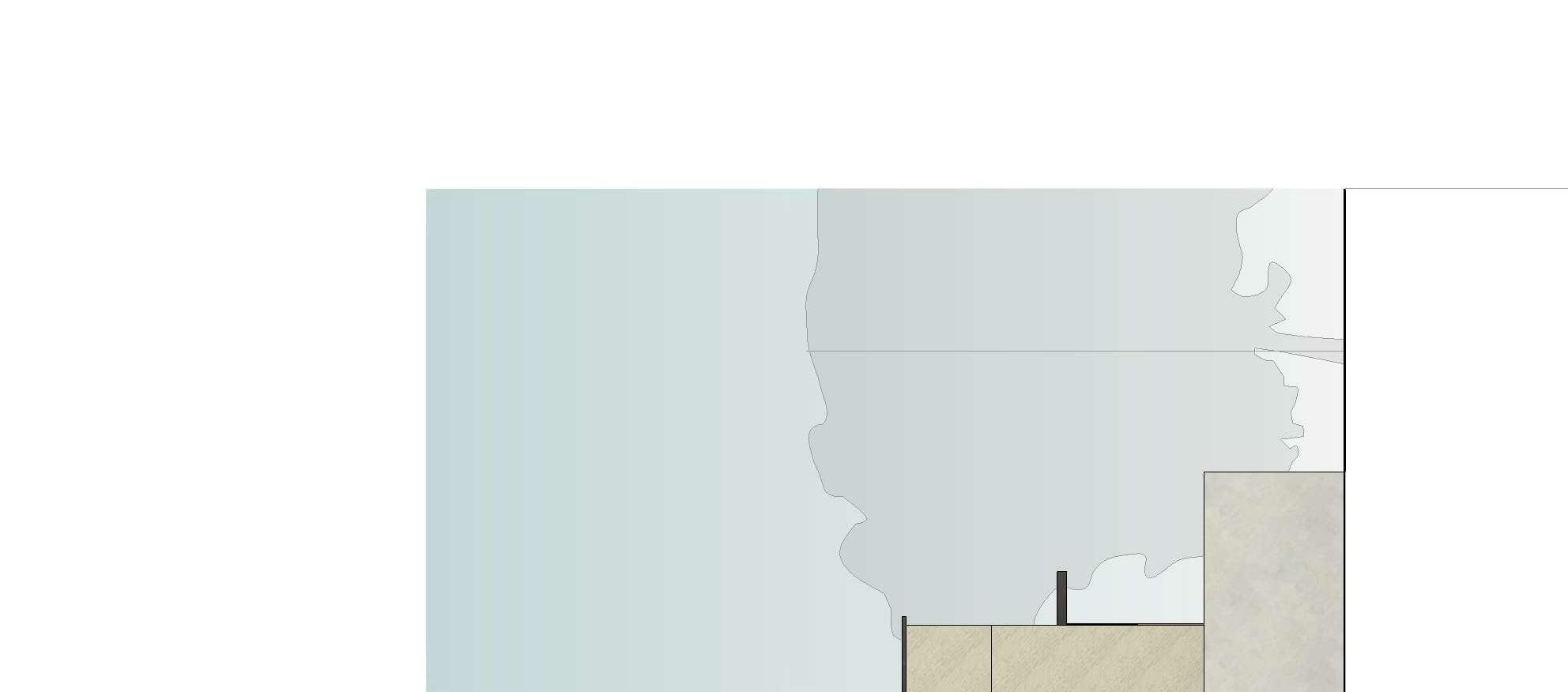
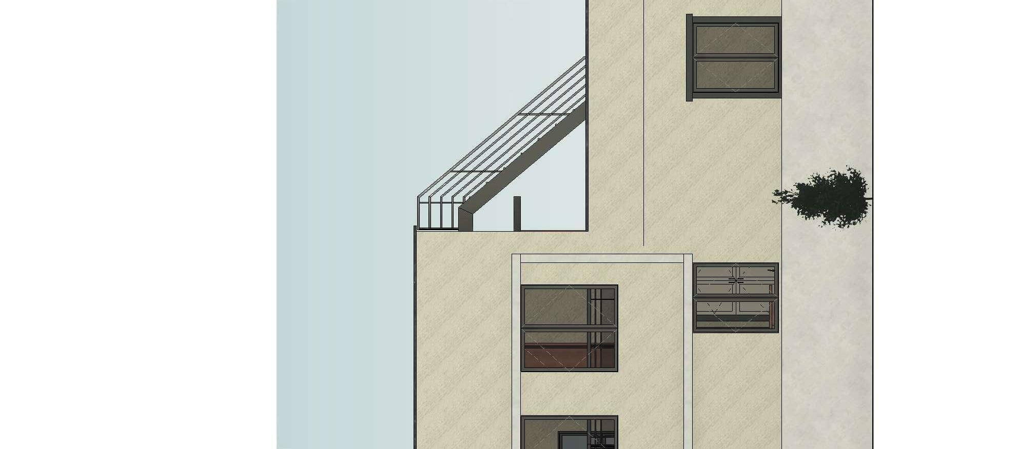
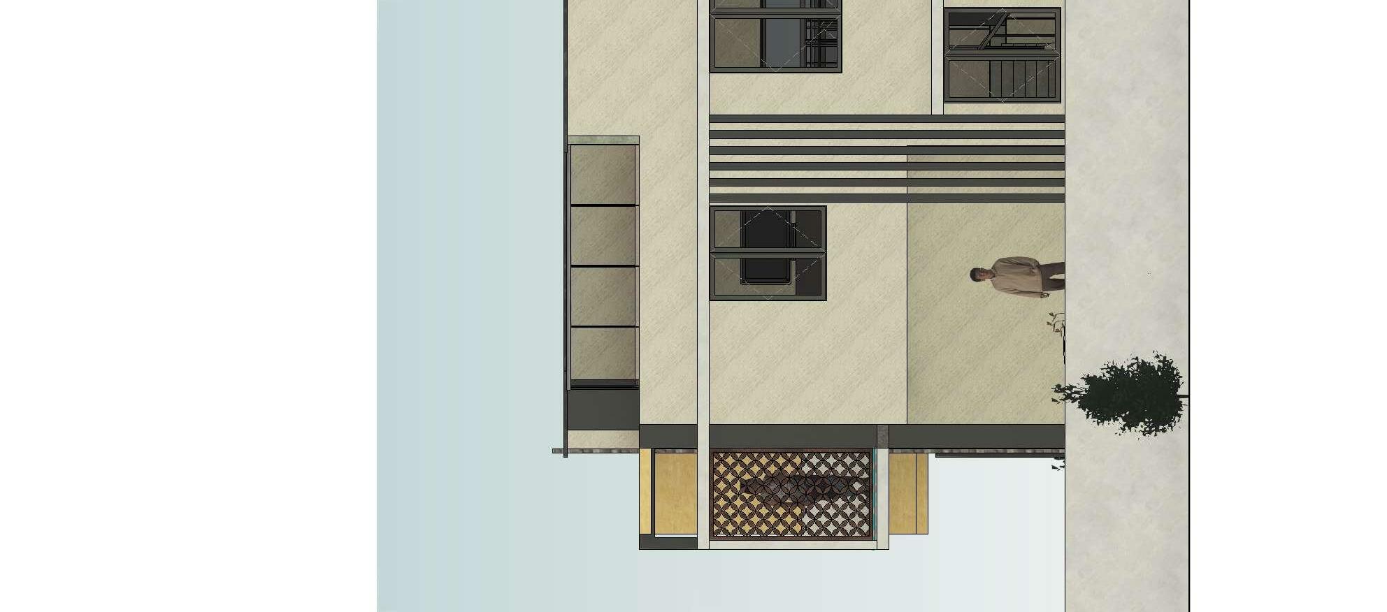
Thk Marble Coping 7978Orange Frost Coloured Asian Paints with Scratch Finish Texture 9" Thk Boundary Wall8250 Winter Moon Asian Paints (Archi Concrete) with Pitted Finish 6" X 6' Steel Hollow Section of 5mm Thickness Finished with Powdered Coating 12mm Thk Glossy & Transparent Glass X105Lemon Ole Coloured Asian Paints with Createx Scratch Finish Ocean Pattern 6" Thk Shading Device with 8250 Winter Moon Asian Paints (Archi Concrete) with Pitted Finish 4 1/2" Thk Shading Device 6"X4" Steel Hollow Section of 5mm Thickness Finished with Powdered Coating 12mm Thk CNC Panel made of WPC Steel Staircase 2" Thk 2'0" W2
Coping V1 W2
Thk Natural Stone Cladding with Rough Finish 4 1/2" Thk Duct Wall9631 Charcoal PlumN Coloured Asian Paints with Flat Finish Wooden Plank 6" X 6" Steel Hollow Section of 5mm Thickness Finished with Powdered Coating X105Lemon Ole Coloured Asian Paints with Createx Scratch Finish Ocean Pattern 4 1/2" Thk Parapet Wall8250 Winter Moon Asian Paints (Archi Concrete) with Pitted Finish 6" x 6" Steel Hollow Section of 5mm Thickness Finished with Powdered Coating Ventilator 9" Thk Boundary Wall8250 Winter Moon Asian Paints (Archi Concrete) with Pitted Finish Planter Box 9'3"
Coping 2" V1 W5 15'9"
DISCLAIMER
This document and its contents are the copyright of BRICKS & SPACE ARCHITECTS. Any party receiving this document does so in confidence and agrees that any of the information contained herein shall not be reproduced in whole or in part or disclosed to others without prior written consent of the architect.
A B C D E Terrace Lvl 23'1 1/2" Terrace Parapet Lvl 26'1 1/2" 2' 7 1/2" 2' 1/2"


Planter Box 2' 7 1/2" 2' 1/2"
1/2" 12' 9"
- 10" 8'6"
No.DescriptionDate 1/4" = 1'-0" East 1 1 : 50 West 2

DATE DRAWN BY
11/24/22 Ar. Shilpa S
Ar. Bharathi East & West Elevation

SHEET NUMBER
SCALE (A1) REVISION NO
CHECKED BY NORTH
A108 00
PROJECT CLIENT DOCUMENT STATUS

APPROVED BY As indicated Mr. Selva Kumar Residence Mr. Selva Kumar
Please refer all R.C.C details in conjunction with Structural Drawing. 4.
DISCLAIMER BRICKS & SPACE ARCHITECTS
This document and its contents are the copyright of BRICKS & SPACE ARCHITECTS. Any party receiving this document does so in confidence and agrees that any of the information contained herein shall not be reproduced in whole or in part or disclosed to others without prior written consent of the architect.
Ar.Bharathi Ph : +019944344347 Email : bharathishanmuganathan1997 @gmail.com Address :
DATE DRAWN BY
12/02/22 Ar. Shilpa S
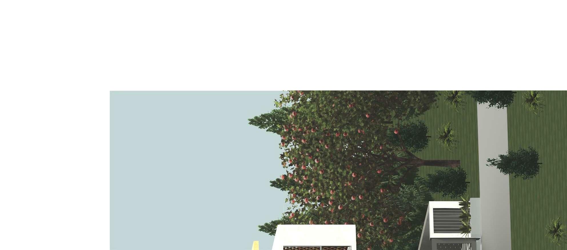
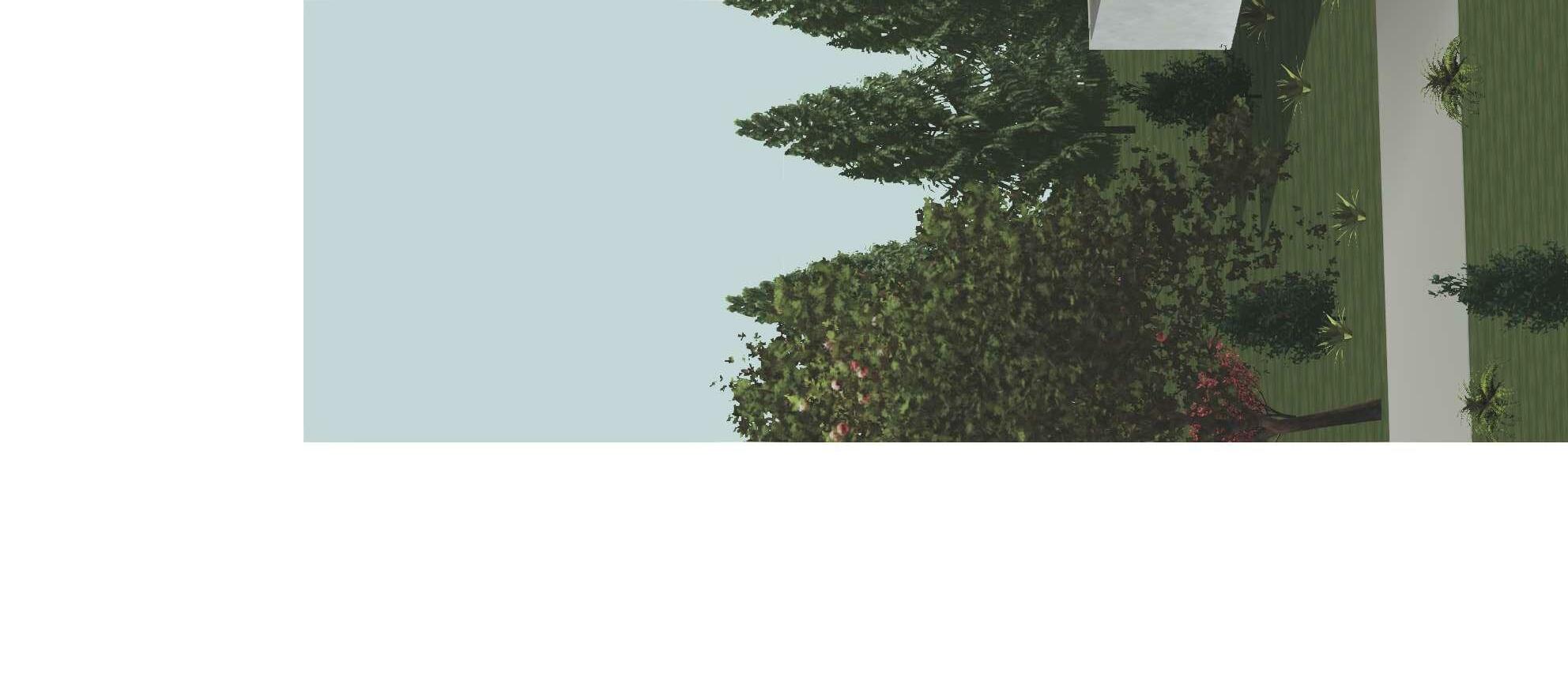
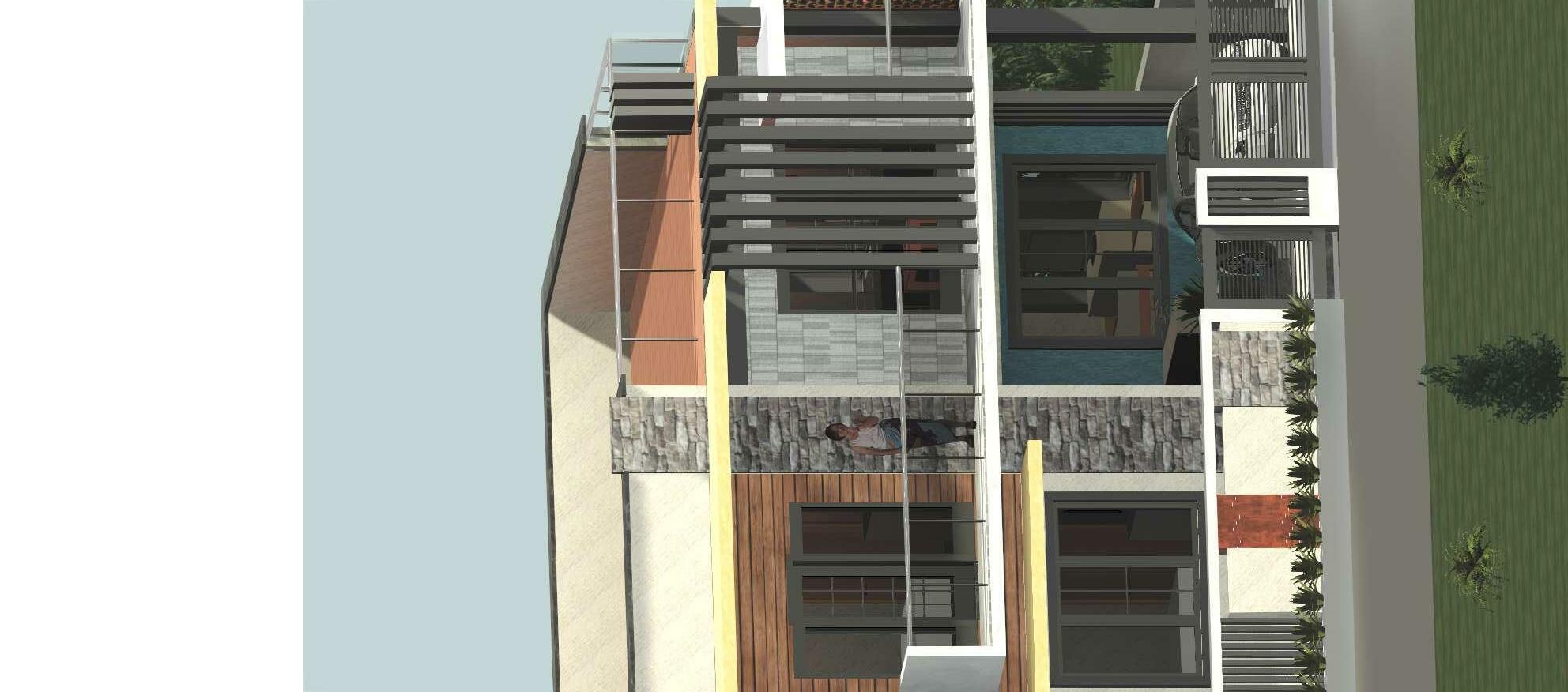
Ar. Bharathi Perspective View
SCALE (A1) REVISION NO
CHECKED BY NORTH
00 No.DescriptionDate South West 1 South East 2
APPROVED BY Mr. Selva Kumar Residence Mr. Selva Kumar
Please refer all R.C.C details in conjunction with Structural Drawing. 4. PROJECT CLIENT DOCUMENT STATUS

All levels are given with respect to centre line of external road taken as 0.00. 3.
Framing to be as per relevant architectural & structural drawings. SHEET NUMBER
A110
Any discrepancy to be brought to the notice of the architect. 5. DRAWING TITLE Working Drawing


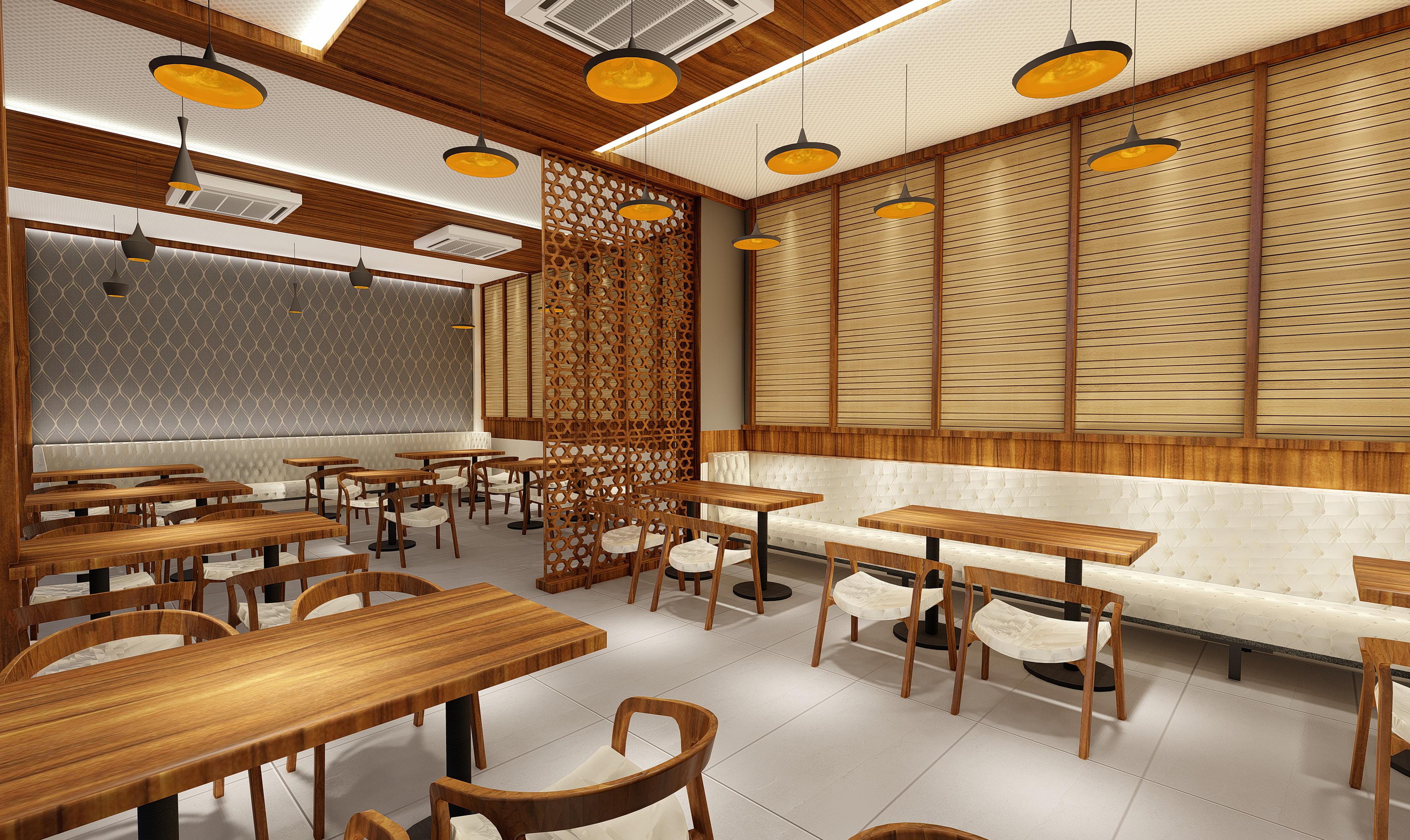
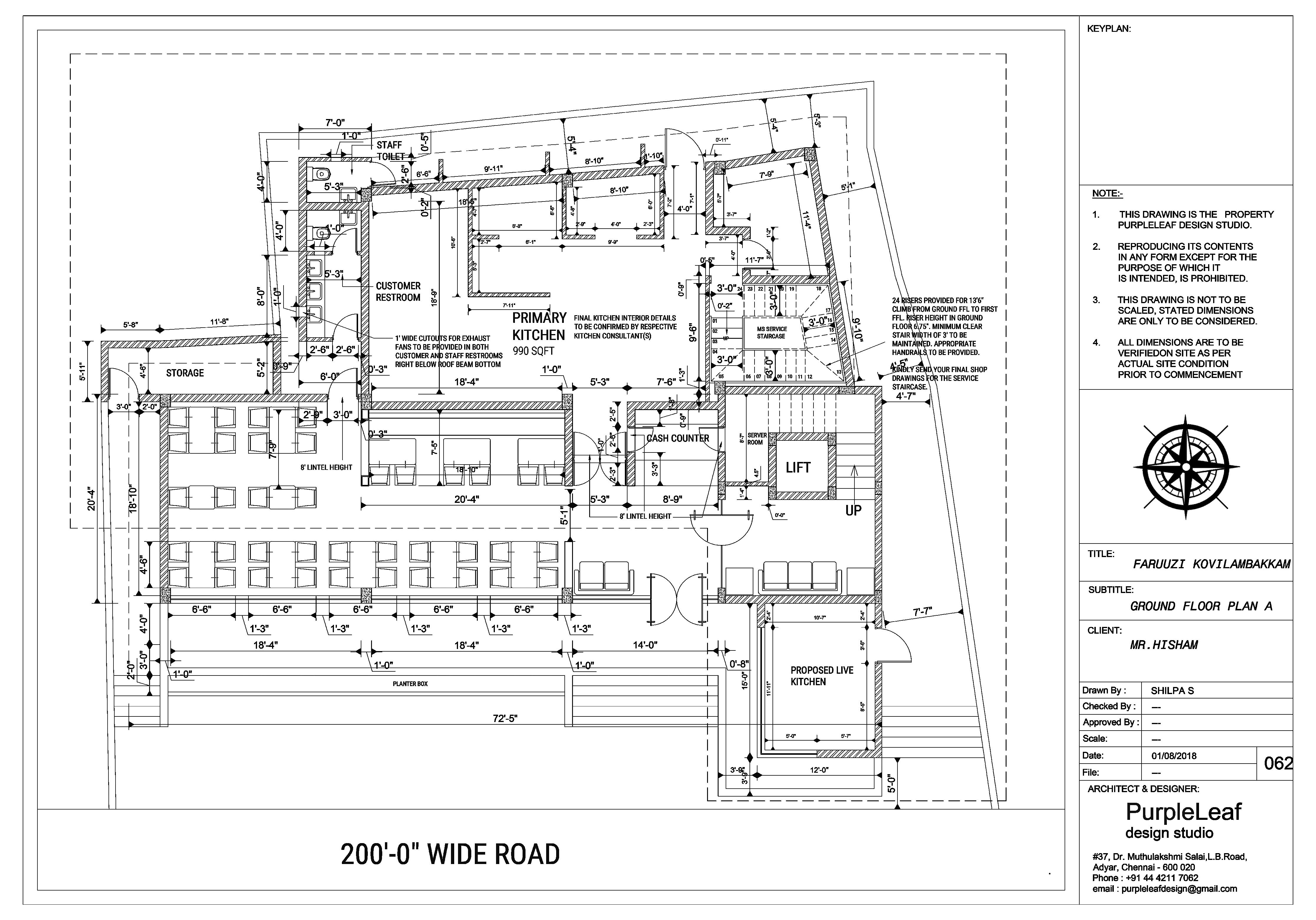
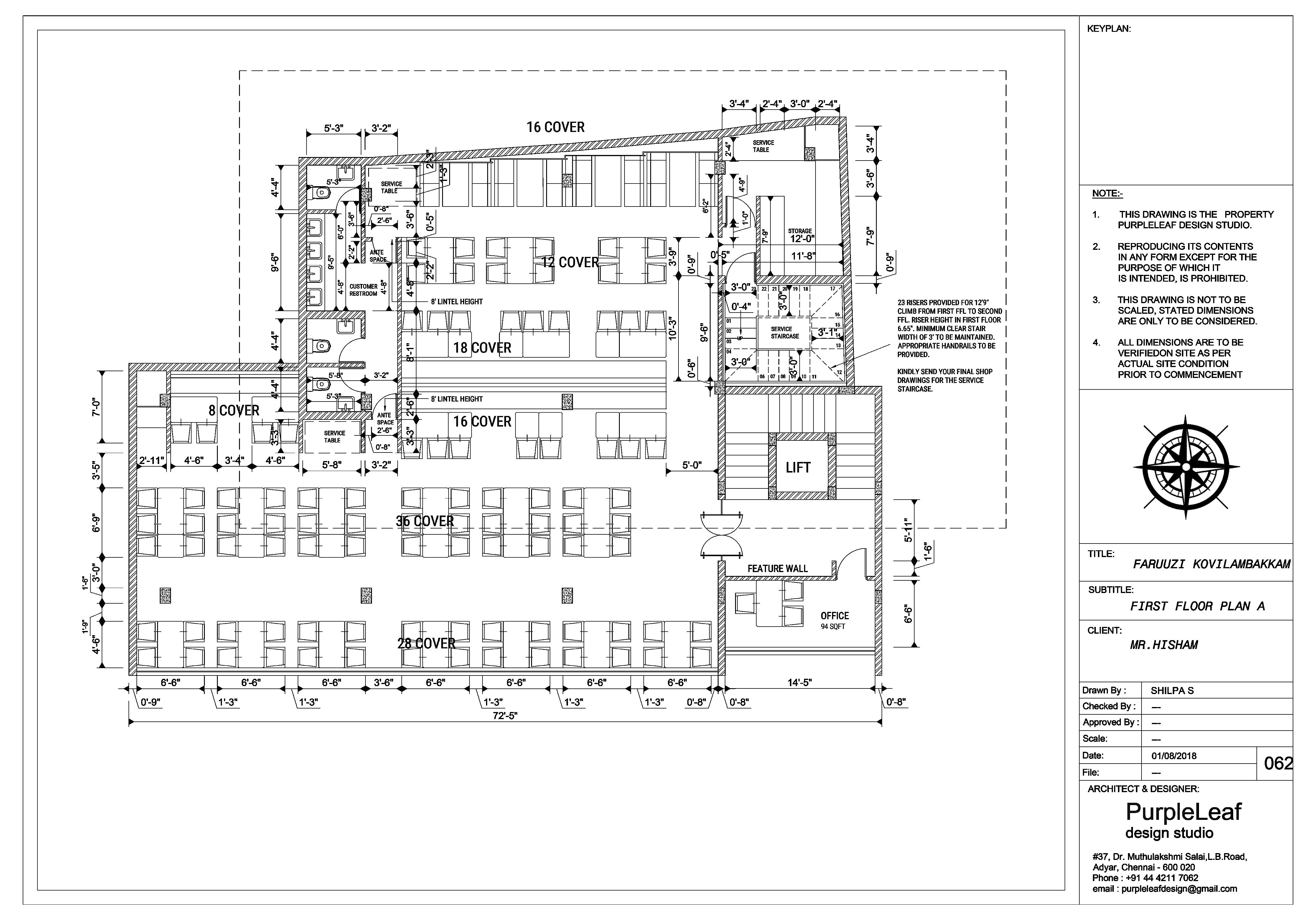
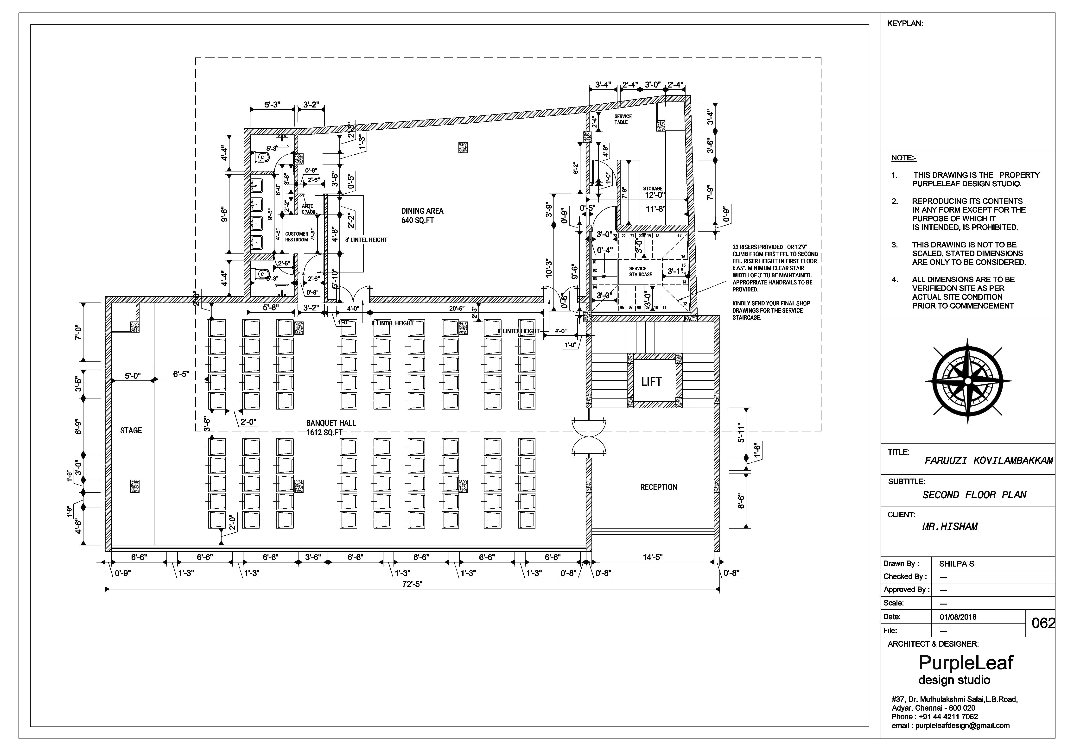
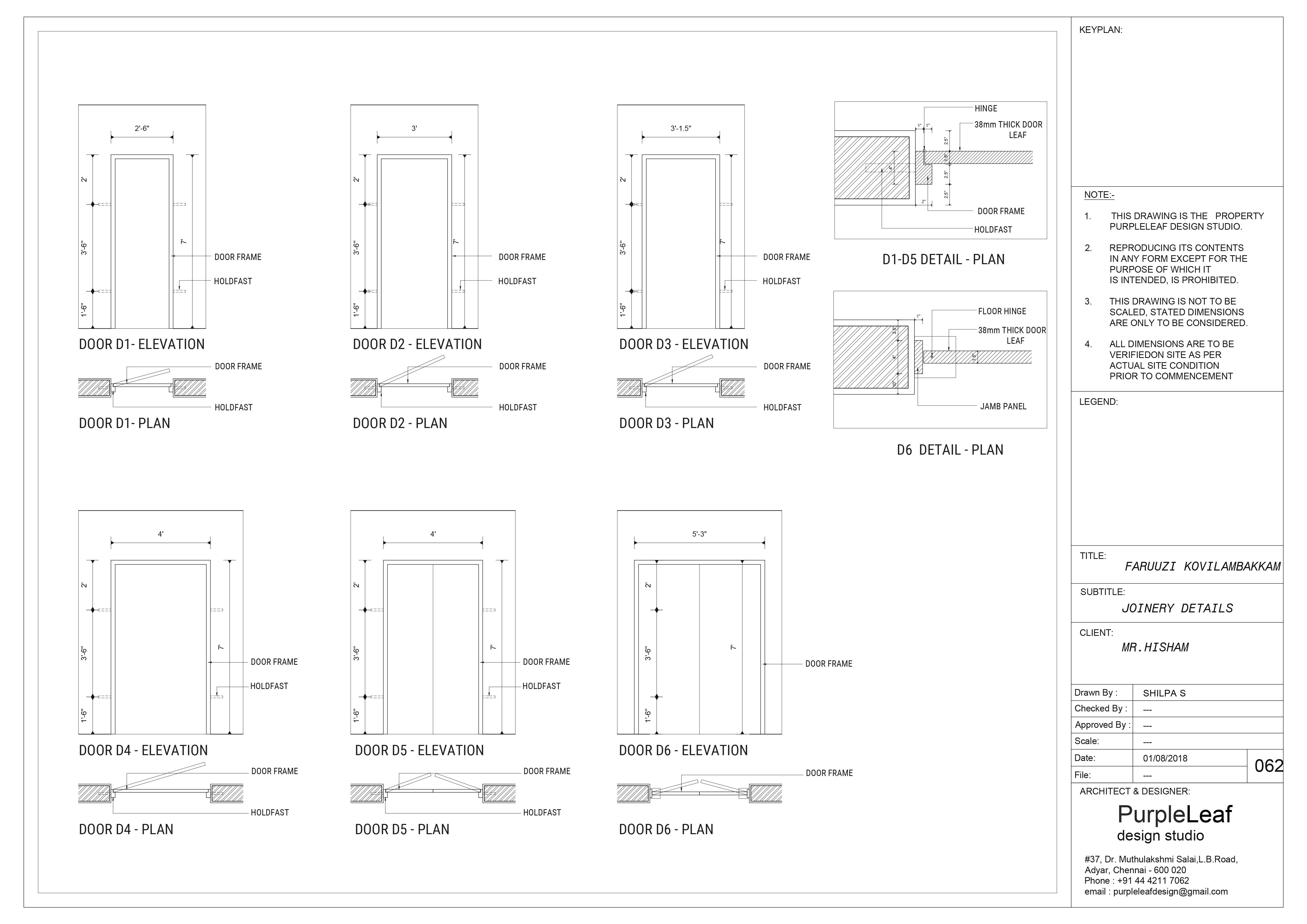
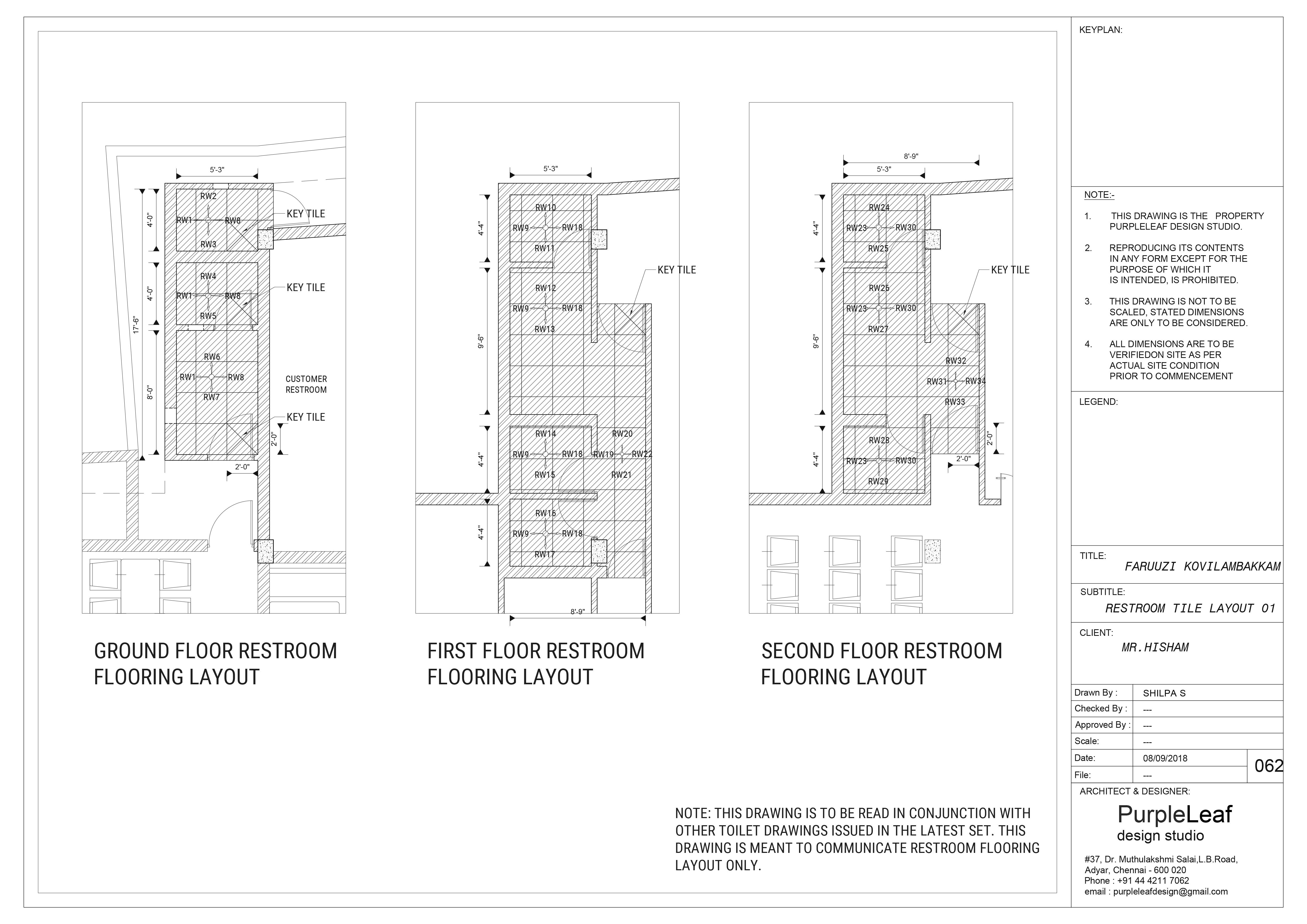
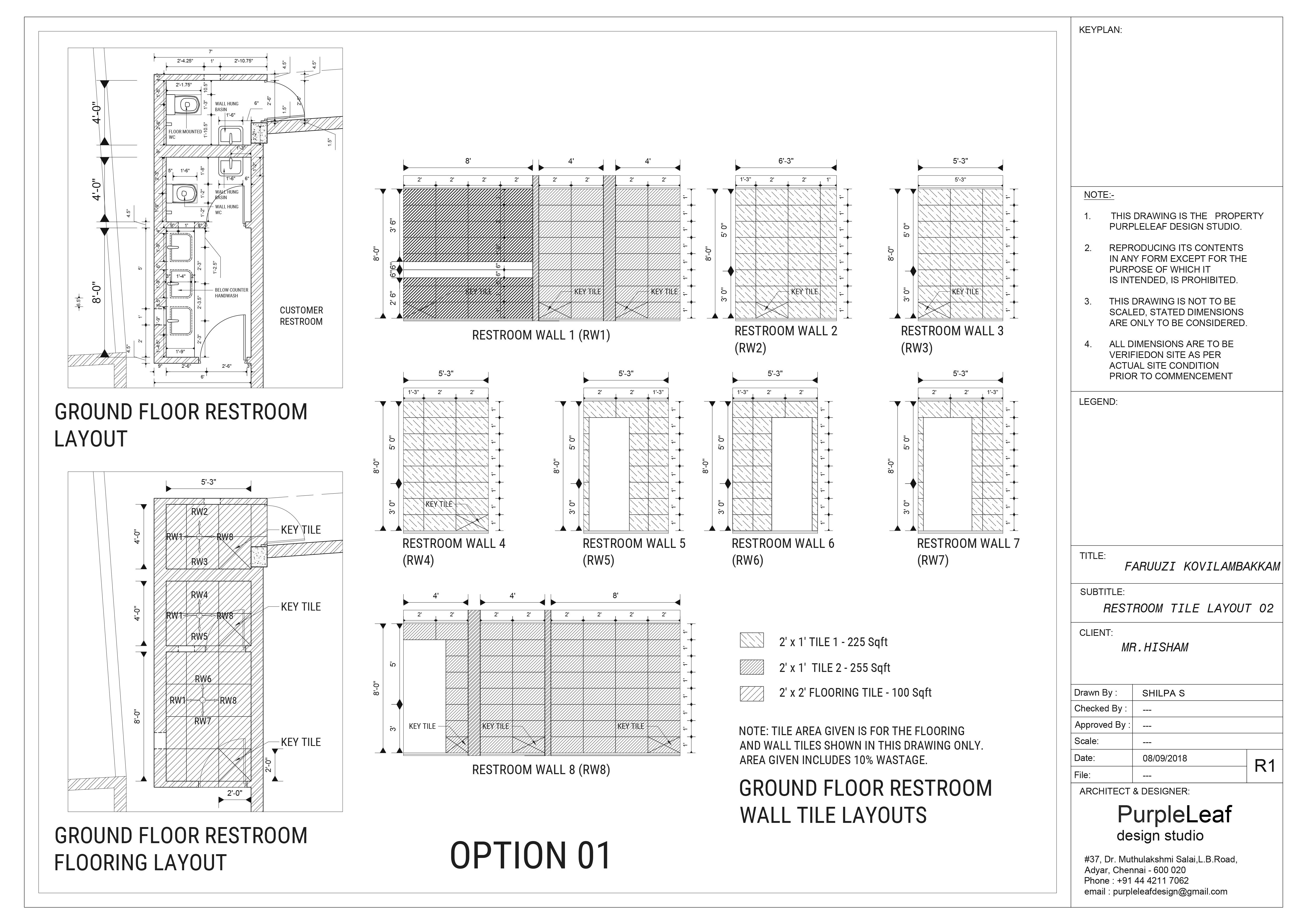
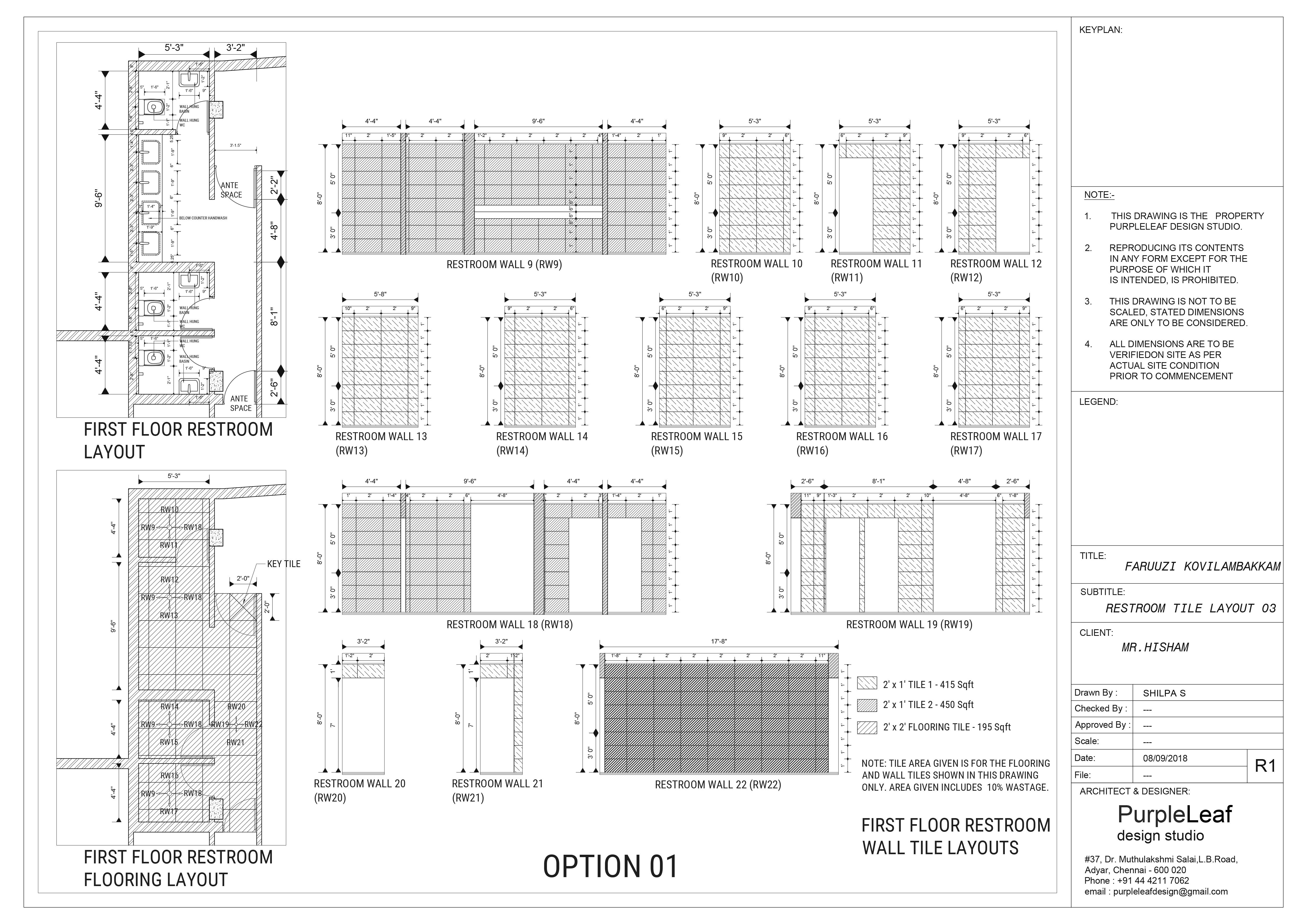
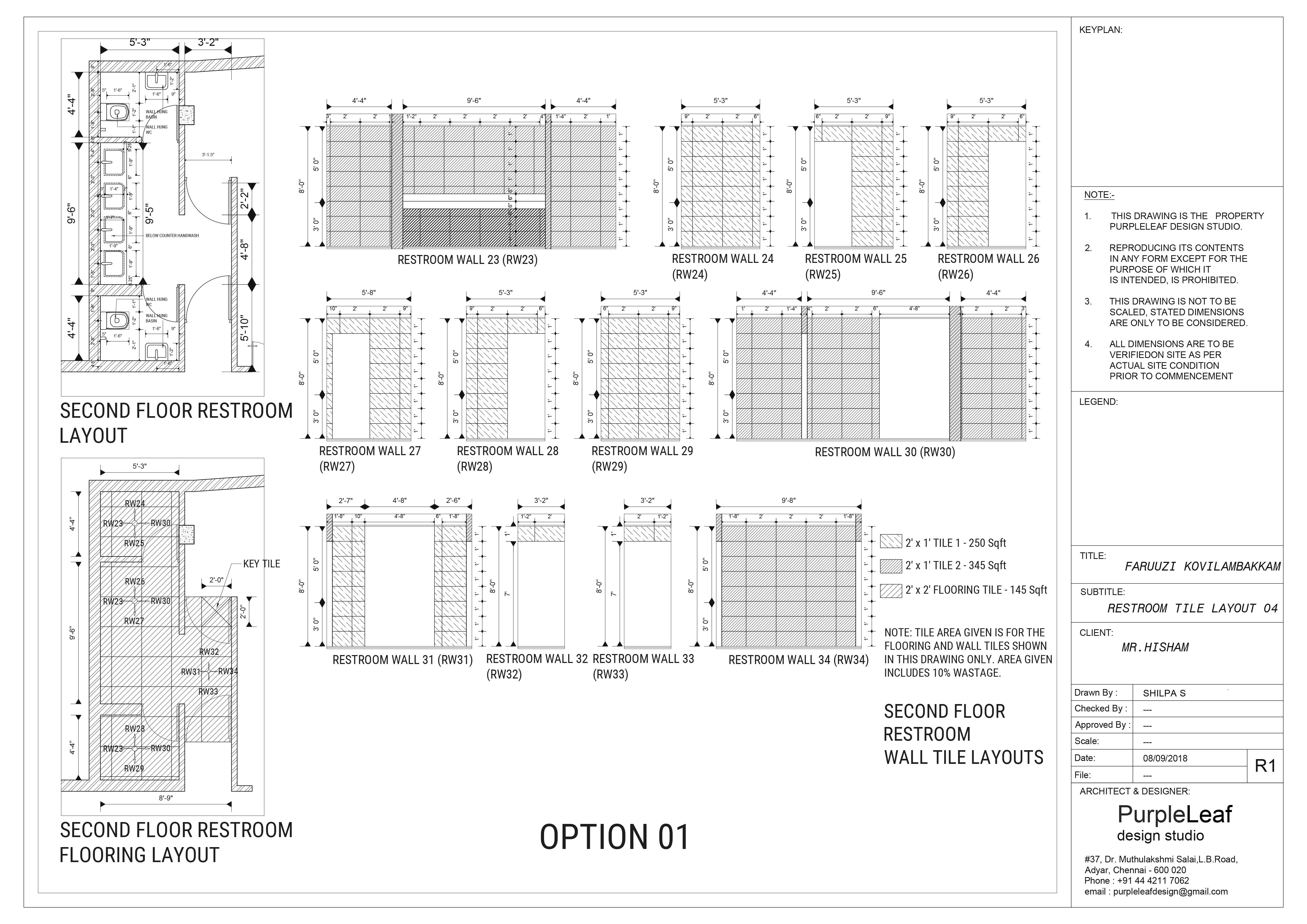
Faruuzi is a well known multicuisine restaurant that possess multiple branches within in Chennai, India. This is an upcoming branch owned by the client Mr.Hisham and the site is located in Kovilambakkam, Chennai.
The aim of this project is to plan and design the interior of the restaurant in such a way that the dining space gets ample amount of light and good view for the occupants. It is also important to focus on the arrangement of furnitures such that maximum number of seats are designed without compromising the architectural standards. The circulation between public and private area has to be ensured. It is a multi level restaurant where banquet hall to be provided.
Site location - Kovilambakkam, Chennai
Site area - 5110 SqFt
Typology - Commercial
Program - Dining area, kitchen, banquet hall
AutoCAD
