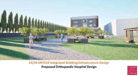
23/24-ENT510 Integrated Building/Infrastructure Design
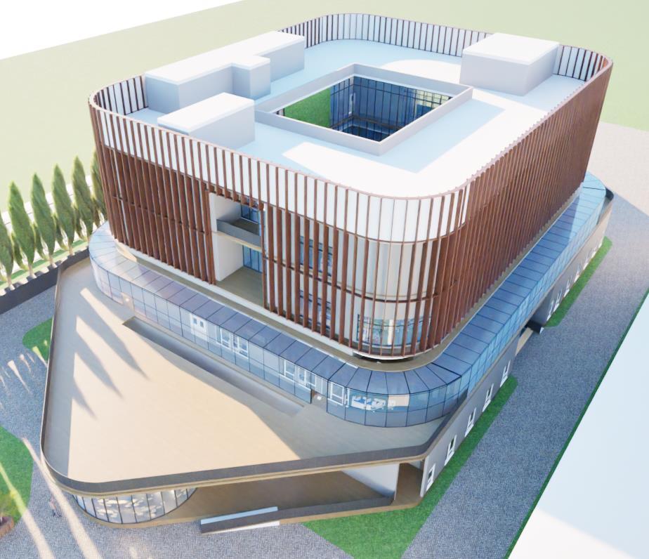
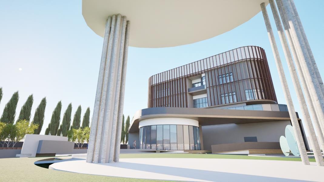
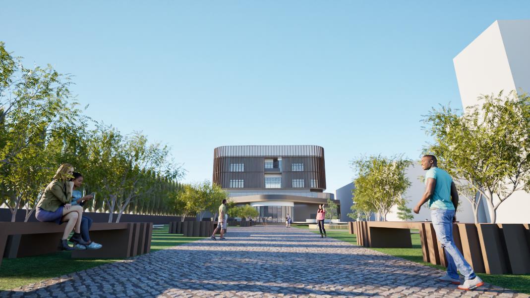
Proposed Orthopaedic Hospital Design
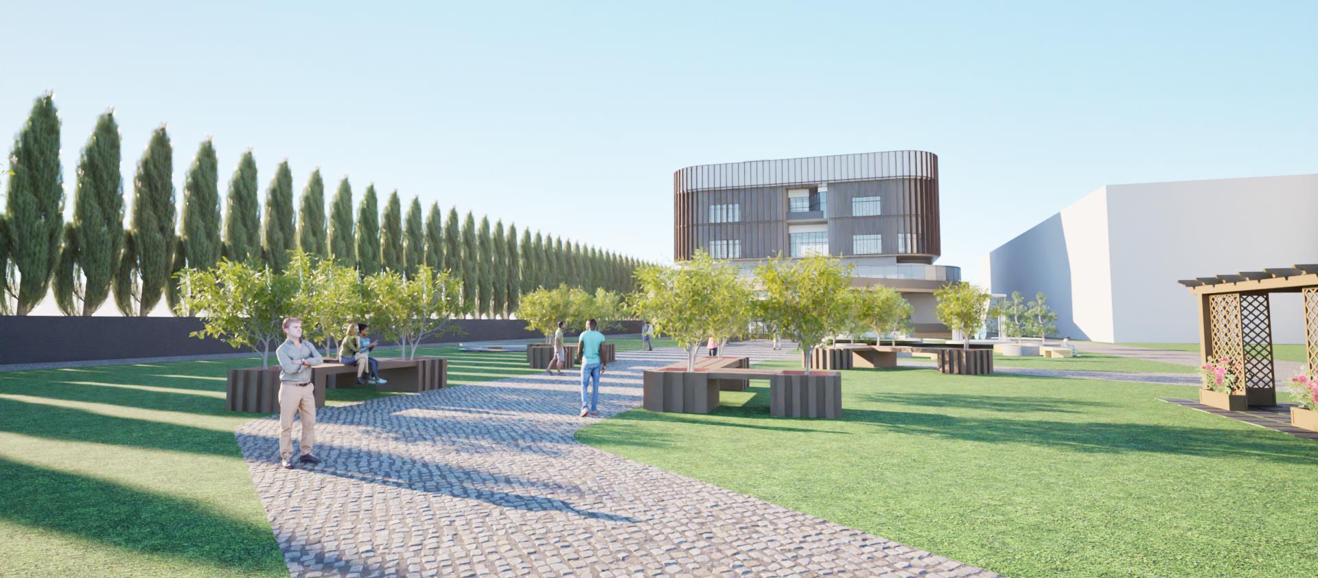
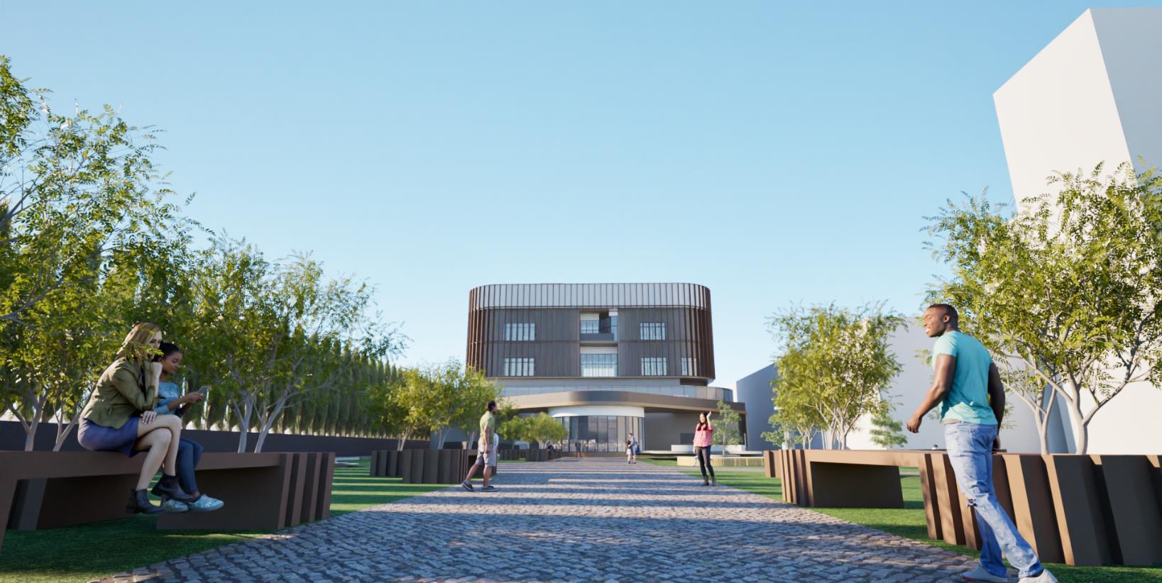
• A proposal for the design of an orthopedic hospital in Cardiff is to be developed, incorporating the specified amenities outlined in the brief below.
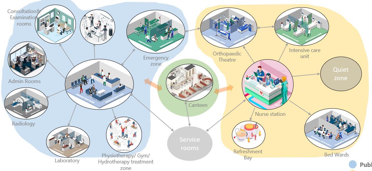
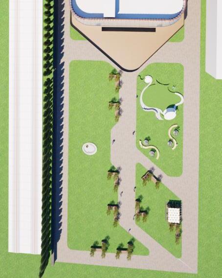
• The design proposal will align with the site conditions, featuring a comprehensive site analysis and a detailed plan.
• Additionally, the proposed design will include an integrated building model.
Orthopedic Hospital Design brief :
• Orthopedic theatres
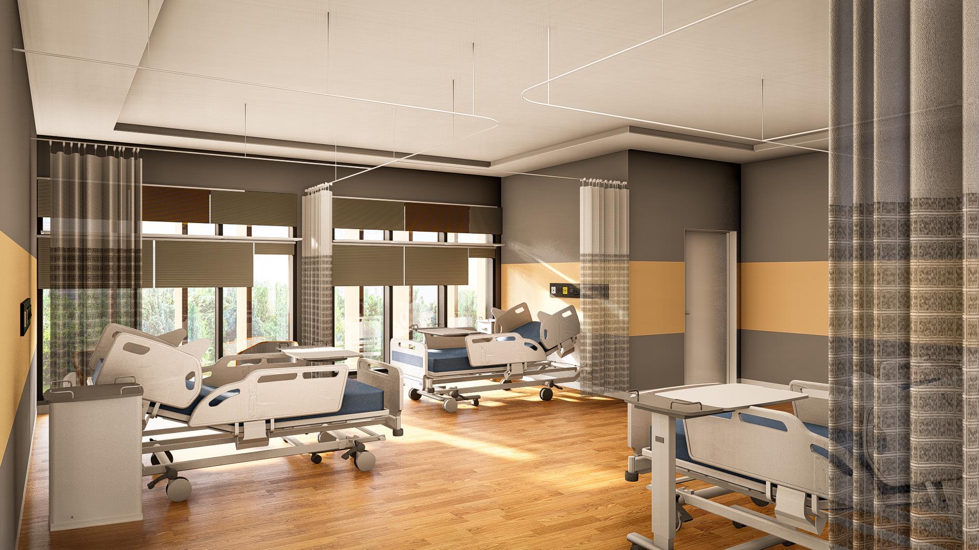
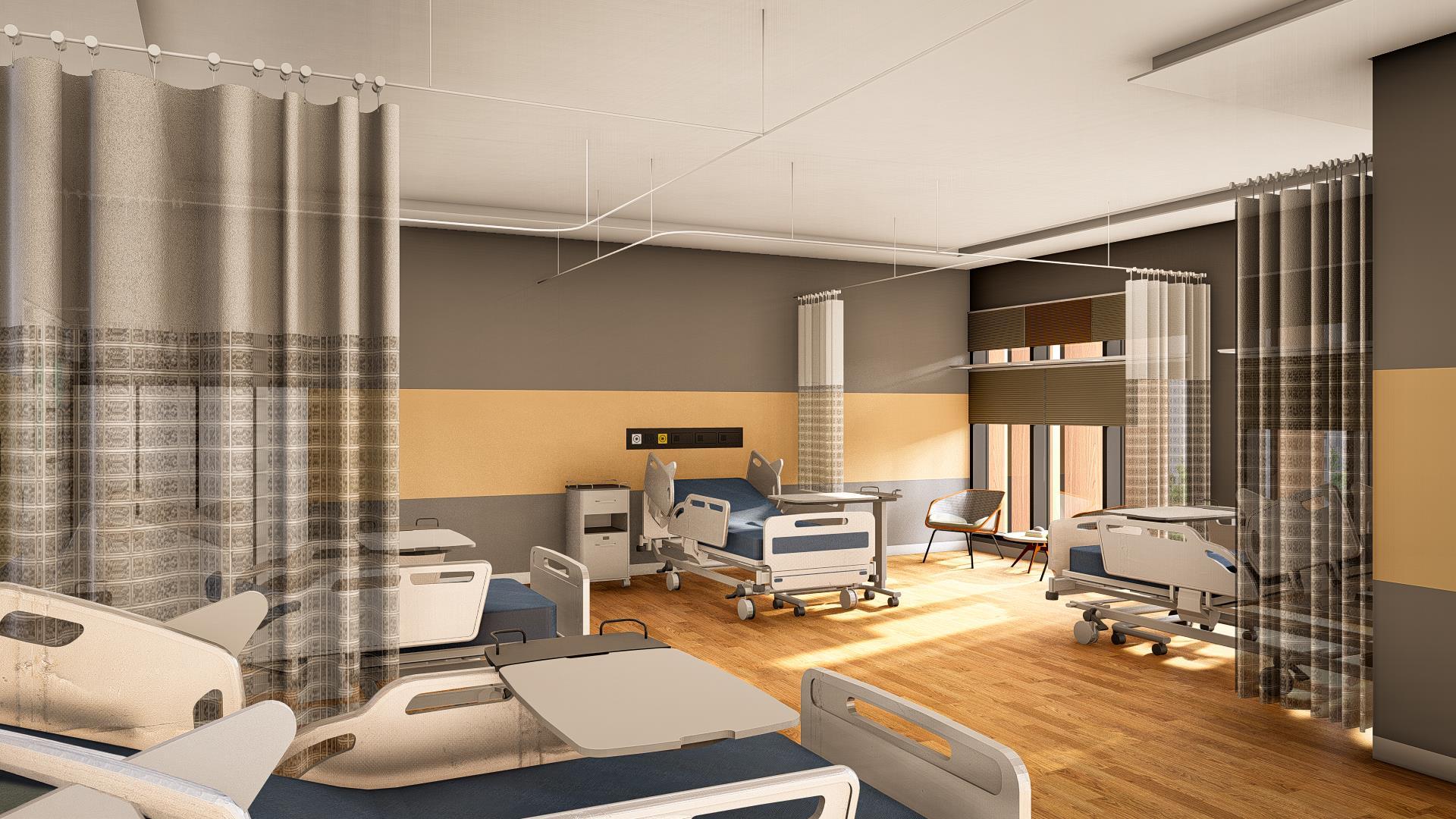
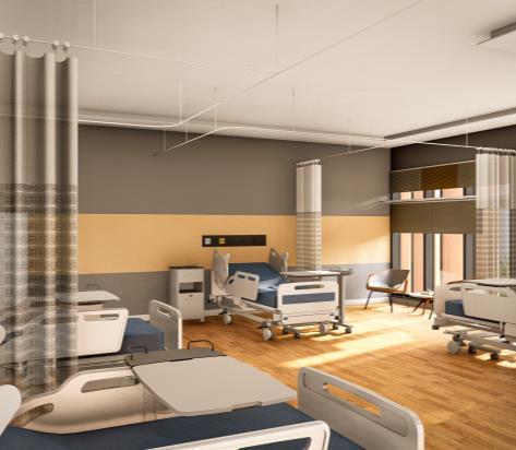
• 18 step down bed wards
• 24 bed wards
• Outpatients
• Physiotherapy
• Café / dining
• Plant room
• Communications
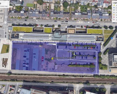
• Site Area- 9391.43 sqm
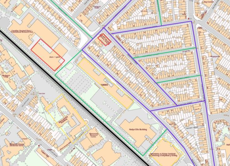
• Typology- Public Hospital Maindy Road, Cardiff CF24 4HQ
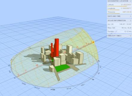
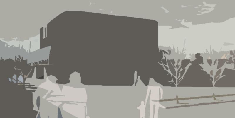
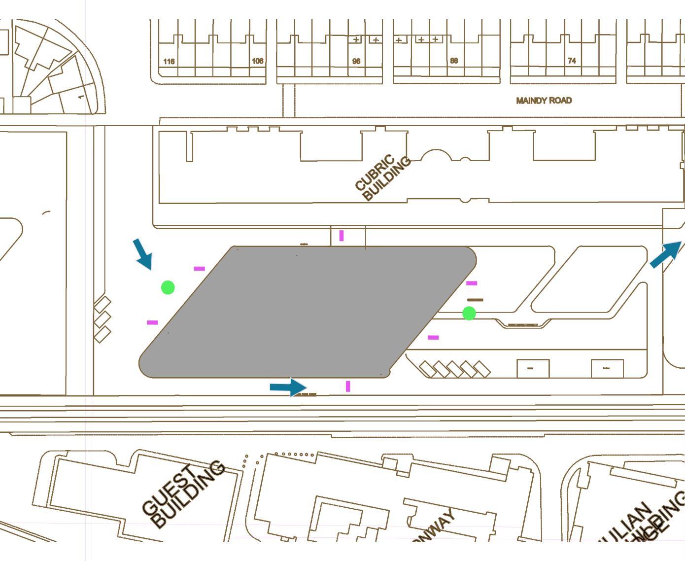
• The cubric building serves as a wall separating the residential area and south sides-built structures are low providing the site an effective opportunity to harvest sunlight.
• Additionally, there are two entrance points on the property that can be used to offer distinct entrances as well as exits.
• The location is particularly vulnerable to noises and vibrations because of the railway line. S W O T
Railway track on one side of the property that may interfere with infrastructure
1. There won't be any traffic blocking the entry or exit because the cubric building blocks both the direct view of the location and noise from the main road.
2. There are two helpful and easily accessible locations on this site which are used for the entry and exits or vehicles and ambulances
• At the current location, the topsoil is disturbed.
• The structure is more susceptible to vibrations and noise pollution hence all the quite zones are placed on the adjacent sides
4. The constructed structures are low on the southern side. It provides an opportunity for the area to effectively absorb sunlight hence areas requiring natural light are provided on this side
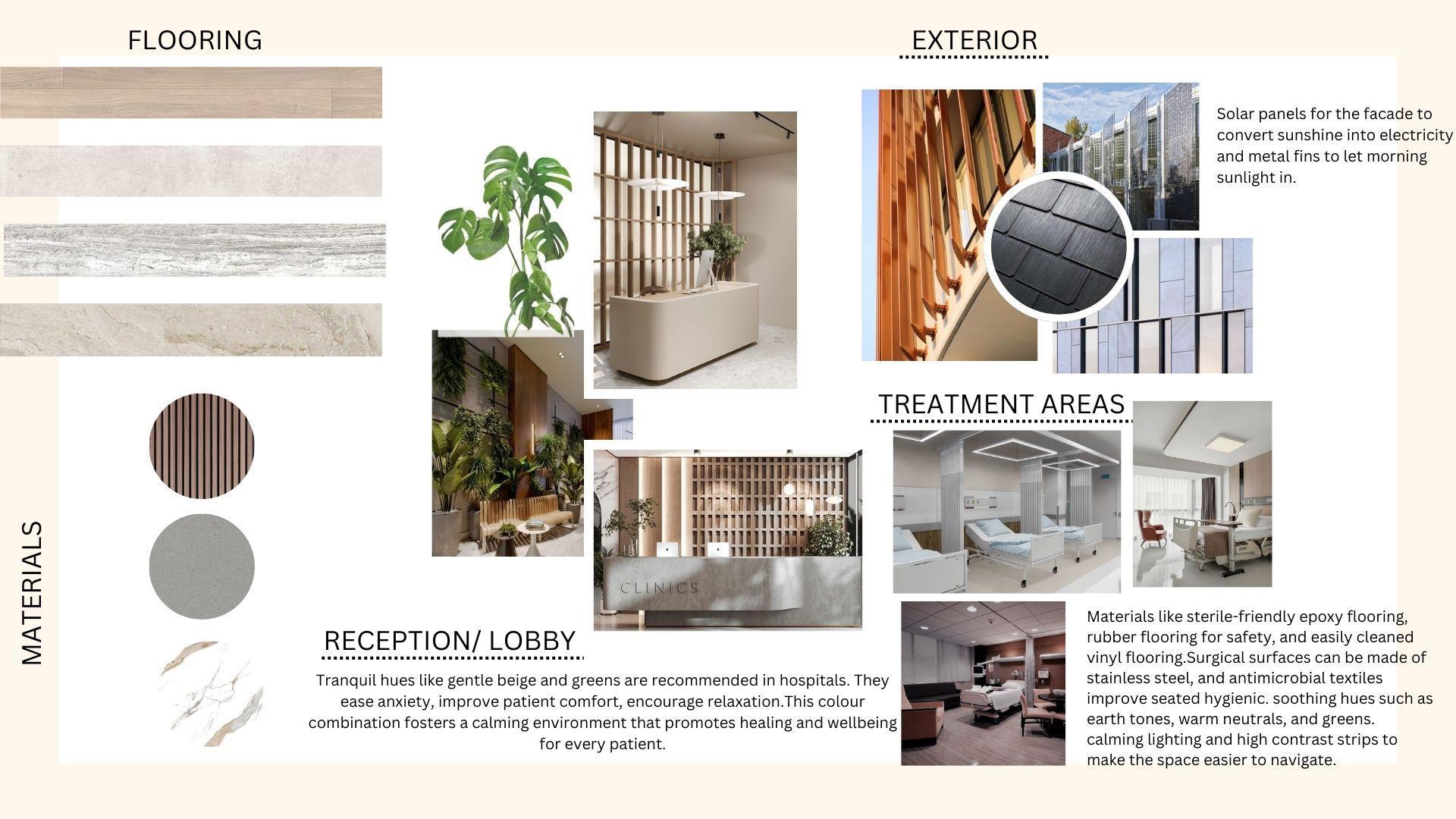
Vinyl Flooring
- Pubic zones
Linoleum
- Operation theater
Tile or stone with radient heating
- Wet zones
Epoxy flooring
Anti-microbial surfaces
Solid surface countertops
Metal fins
BIPV glass panels
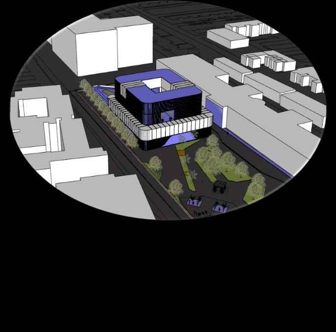
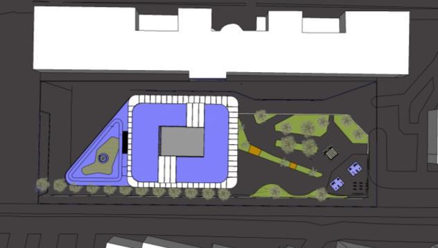
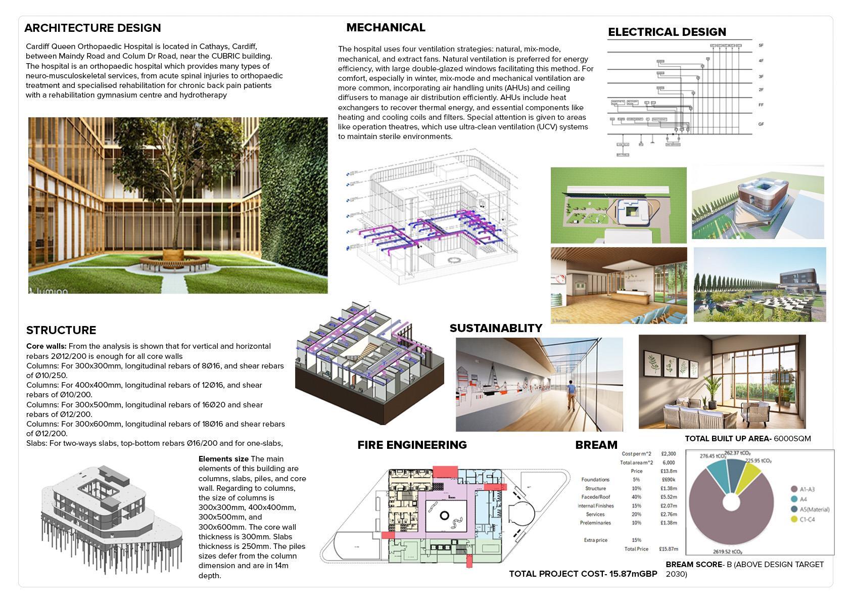
ARCHITECTURAL DESIGN
movement
movement
crossing
Vehicle
Pedestrian
Pedestrian
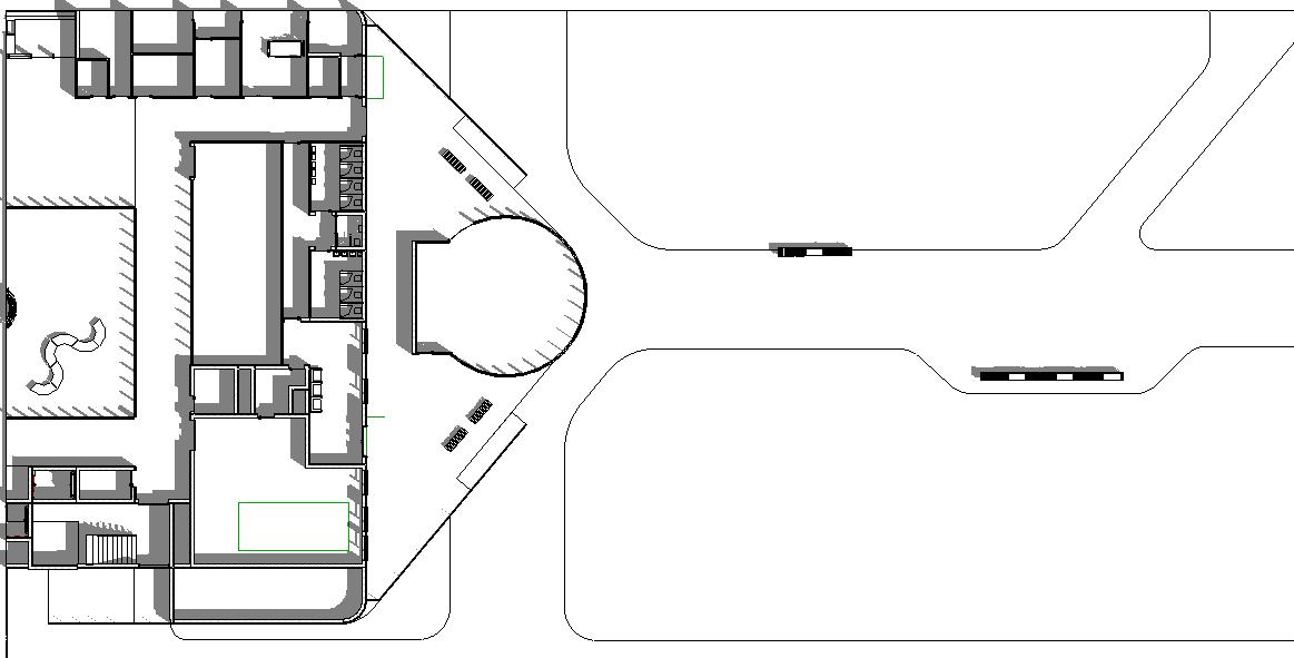
Cafe
Plant room
Train track
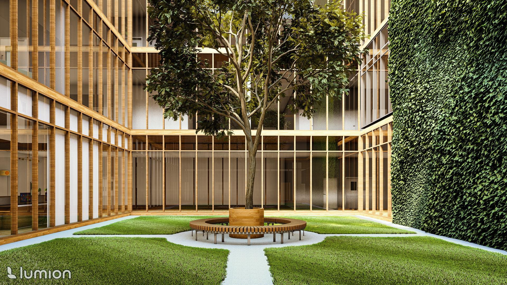
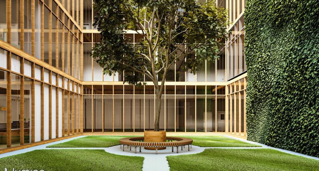
Central courtyard
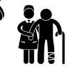
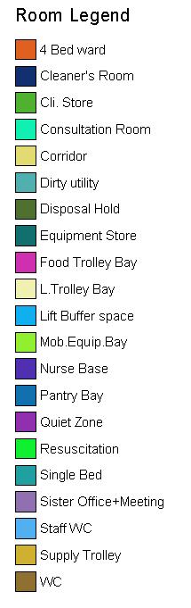
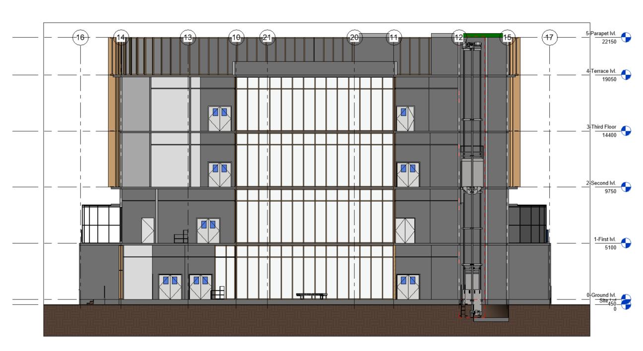
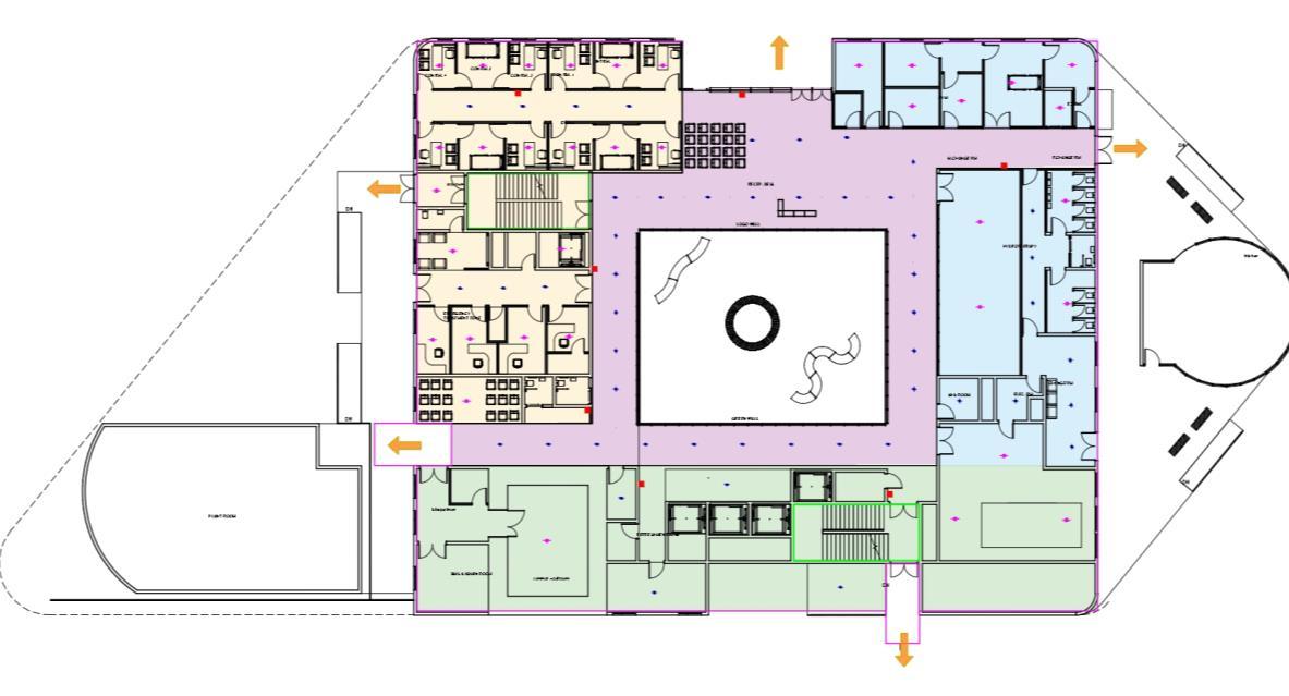
Third Floor :
• Step down Bed Wards, Nurse station
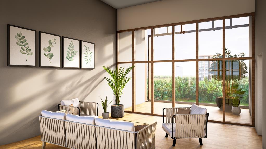
• Natural Ventilated seating area with greeneries
• Quiet Zone
Second Floor :
• Step down Bed Wards, Nurse station
• Open balcony with greeneries
• Quiet Zone
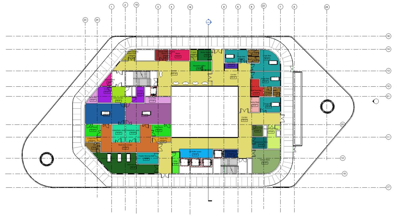
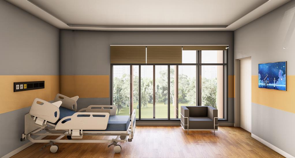
First Floor :
• Orthopedic theatres & Observation ward
• Bed Wards, Nurse station
• Indoor Walking track & Outdoor landscape
zone
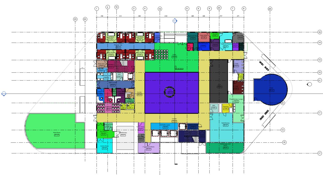
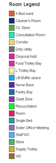
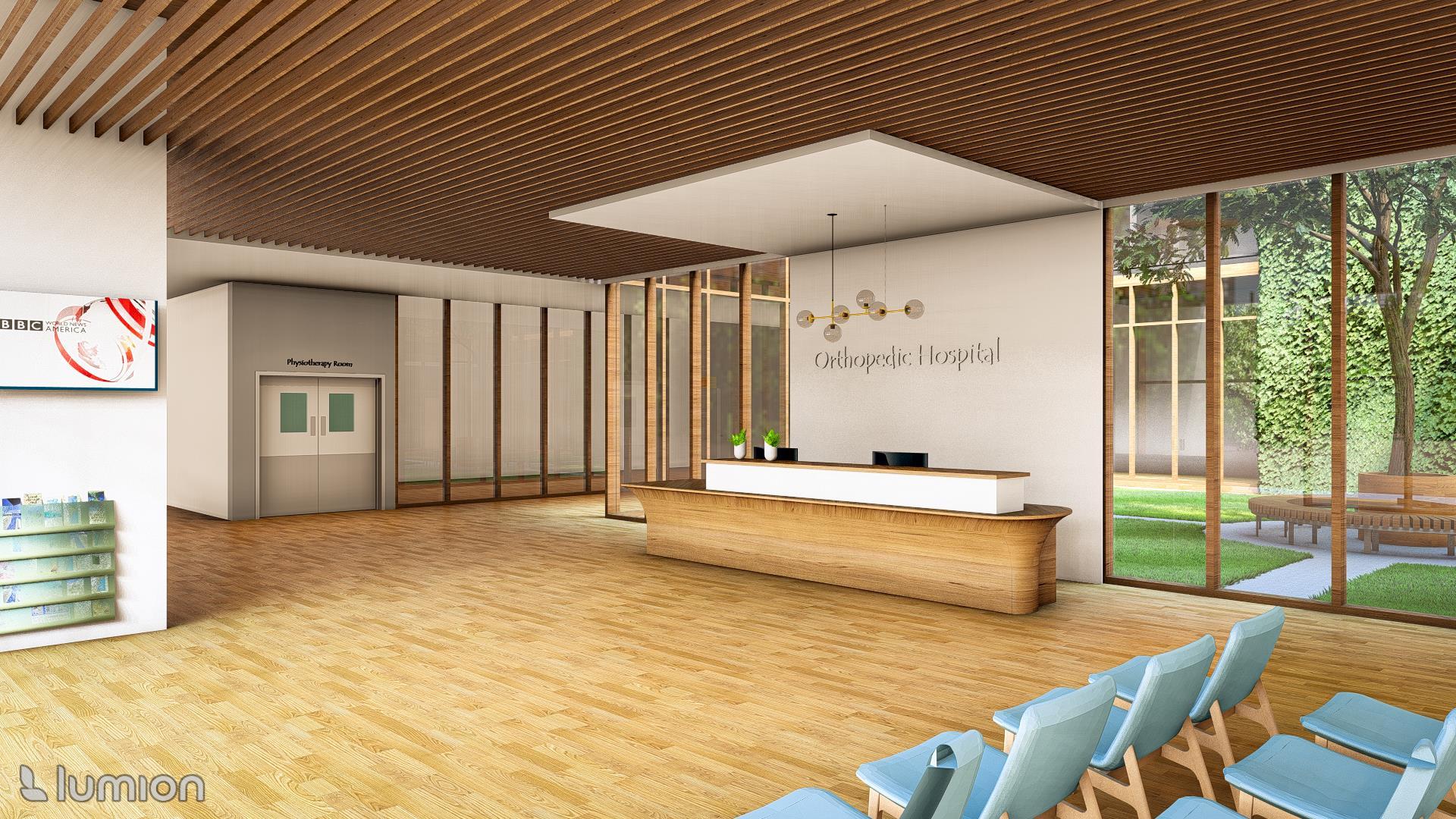
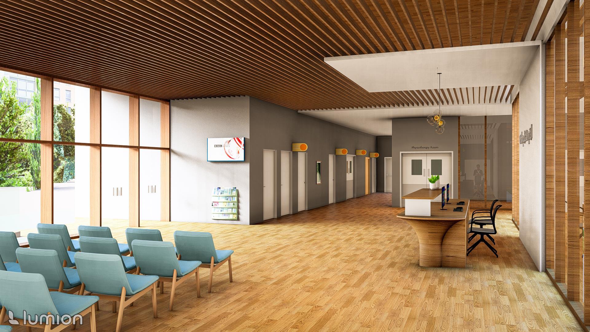
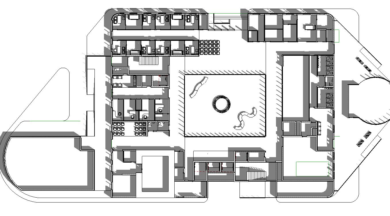
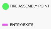
Ground floor :
• Reception, Waiting & Interview Room
• Consultation, Examination, Labs, Radiology rooms
• Gym, Physiotherapy & Hydrology
• Admin & storerooms
• Café / Dining & Plant room
Software: Revit + Sketchup + Twin motion
Software: Revit + Sketchup + Lumion
Software: Revit + Sketchup + Lumion
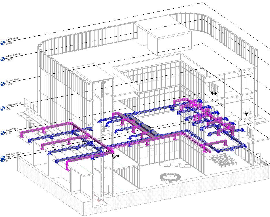
BIM INTEGRATION IN BUILDING SERVICES
Why concrete:
• Cheap material
• Fire resistance
• Anti-Vibration capability
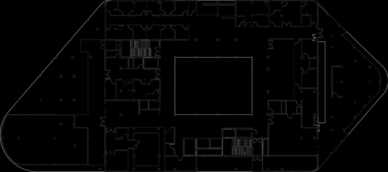
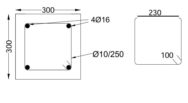
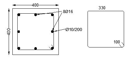
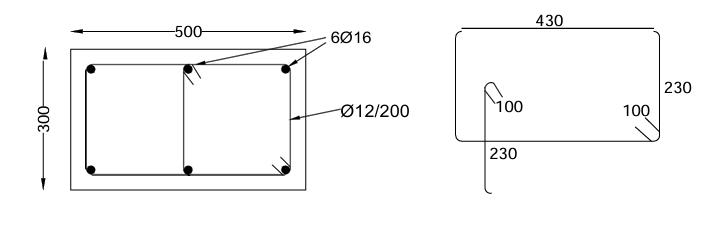
Beamless Construction
C25/30 for slabs
C32/40 for columns, shear walls and piles
B500C type of rebar
Elements size
• Floors (250mm) in every floor
• Columns (300x300mm, 400x400mm, 300x500mm, 500x300mm, 300x600mm, and 600x300mm
• Shear Walls 300mm thickness
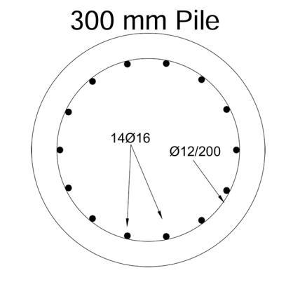
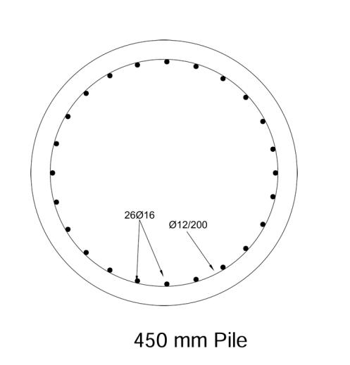
• Piles (300mm for 300x300mm columns, 450mm for 400x400mm, and 600mm for the rest columns and shear walls)
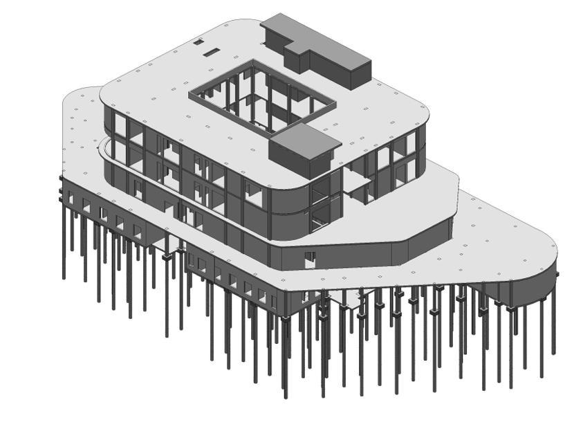
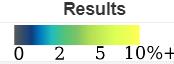
Revit Model - Structures
Combination Loads
• 1.00G+1.00Q
• 1.35G+1.5Q
• 1.00G+1.50S+0.90Wind0
• 1.00G+1.50S+0.90Wind90
• 1.00G+1.50S+0.90Wind180
• 1.00G+1.50S+0.90Wind270
• 1.00G+0.90S+1.50Wind0
• 1.00G+0.90S+1.50Wind90
• 1.00G+0.90S+1.50Wind180
• 1.00G+0.90S+1.50Wind270
(Note: Refer shared drive folder for detailed report)
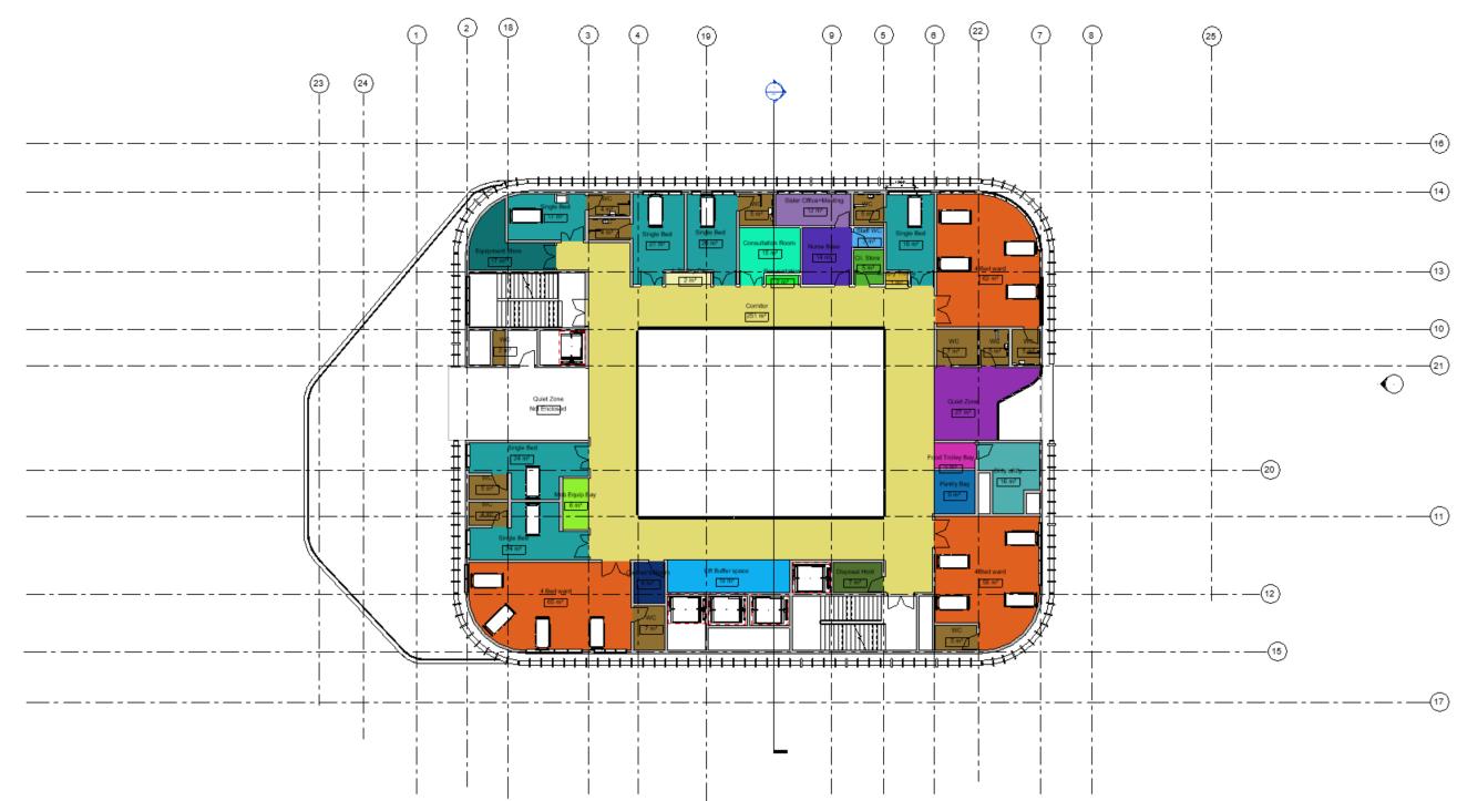
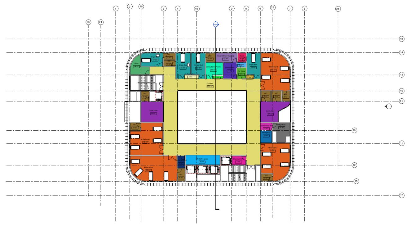
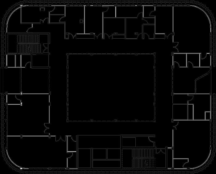
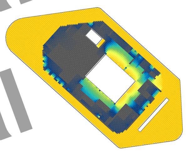
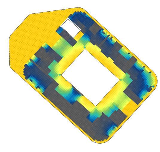
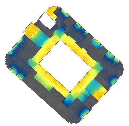
Beamless Construction – Floor plans
G Floor
1st Floor
2nd Floor
3rd Floor
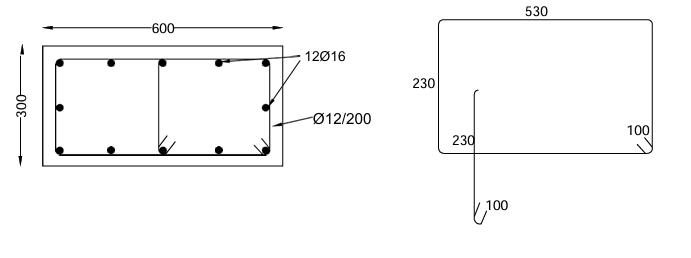
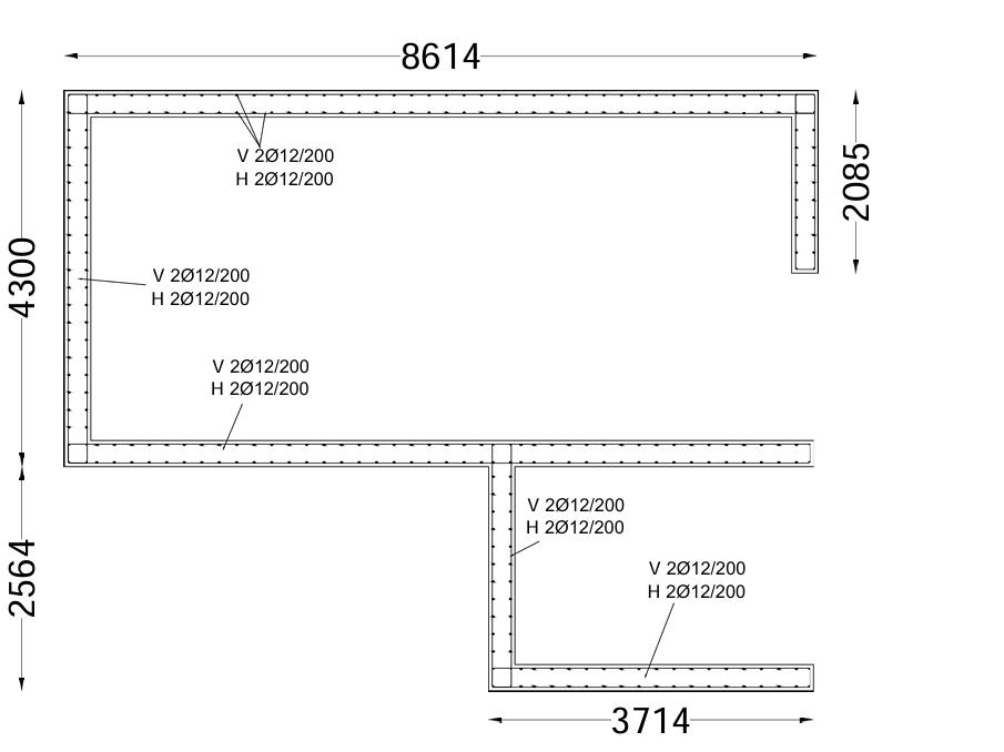
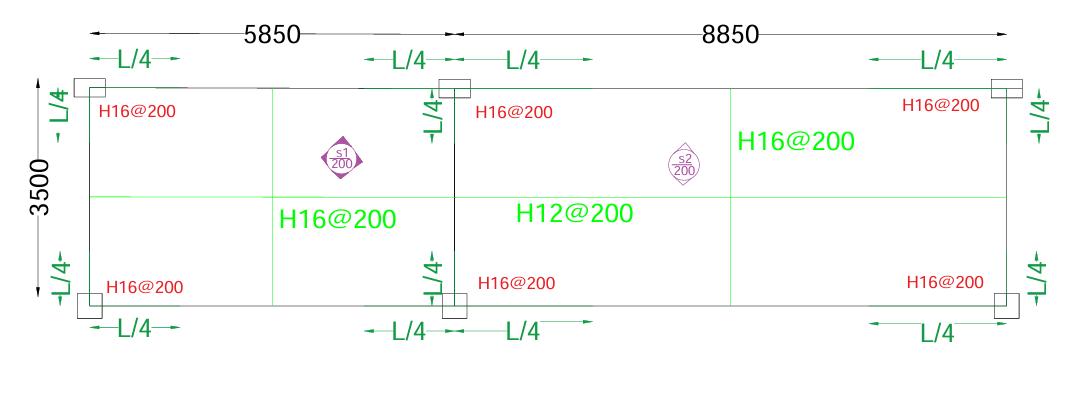
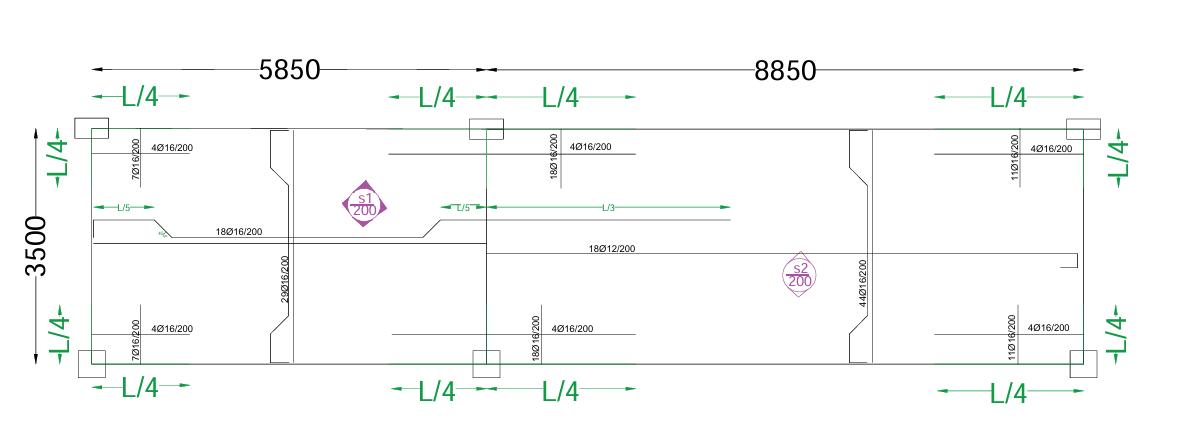
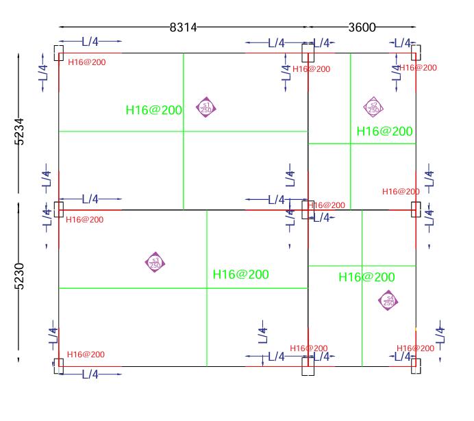
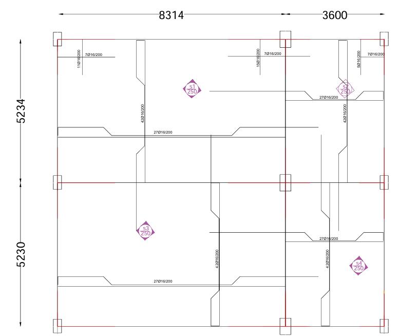
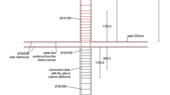
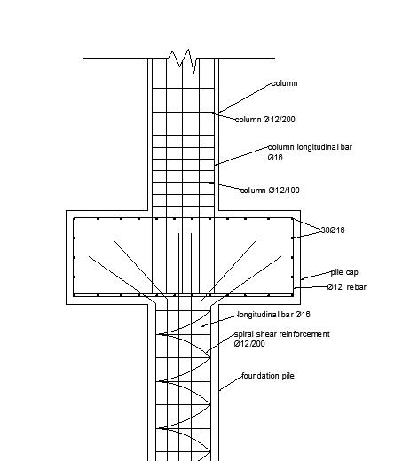
DETAILING
(Note: Refer shared drive folder for detailed report)
Detailing
(Note: Refer shared drive folder for detailed report)
(Note: Refer shared drive folder for detailed report)
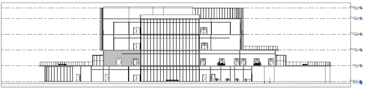
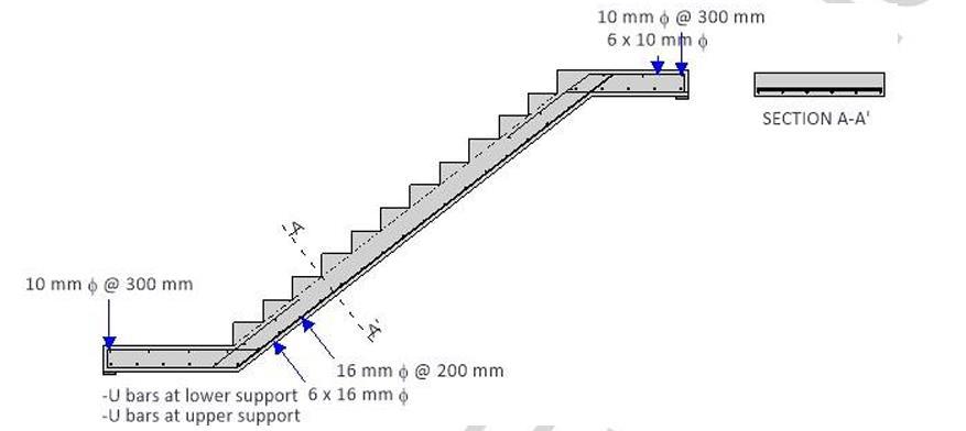
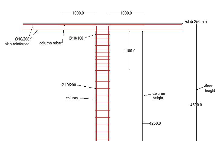
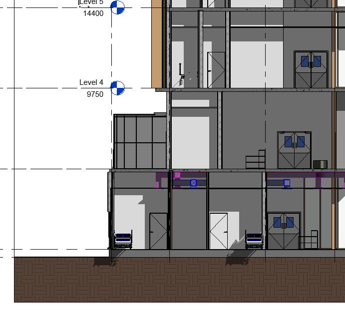
DETAILED SECTION
(Note: Refer shared drive folder for detailed report)
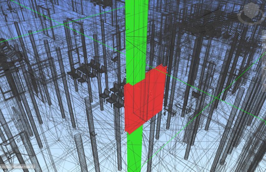
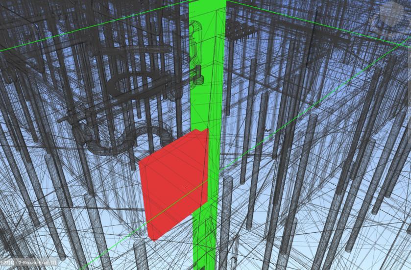
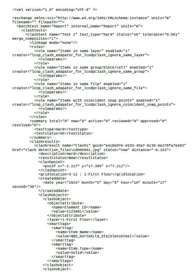
Modeling – Revit 2. Clash detection – Navis works
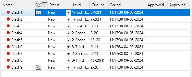
Sample test run Navis work screenshot Report
Coding format report
(Note: Refer shared drive folder for detailed report)
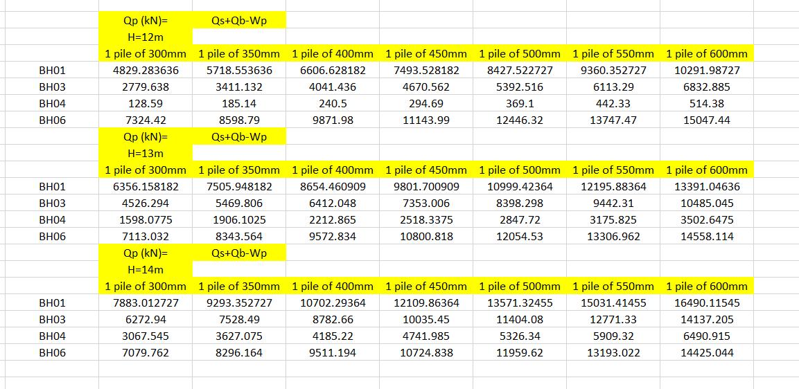
Pile depth → 14m
Column Loads
• C300x300mm → 500 kN
• C400x400mm → 1000 kN
• C300x500mm, 500x300mm → 2000 kN
• C300x600mm, 600x300mm → 3000 kN
• Shear Wall → 2500 kN
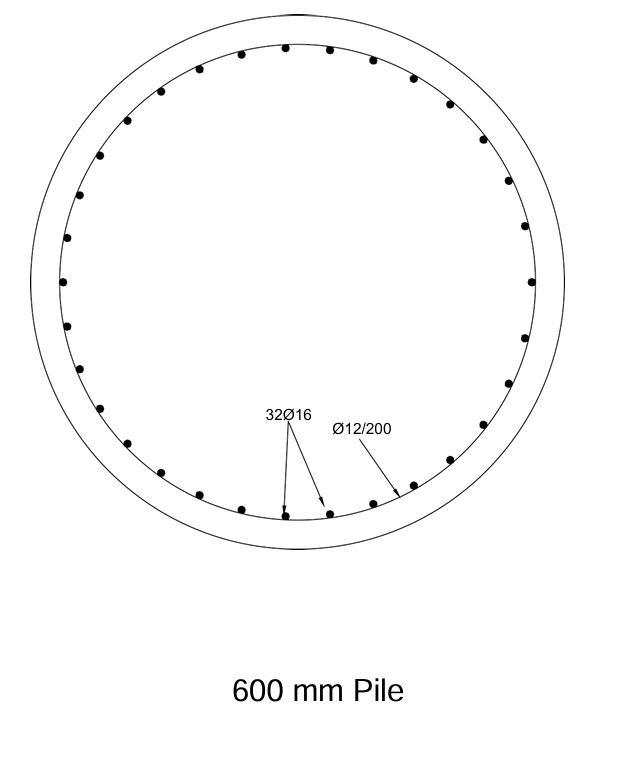
Pile Sections
(Note: Refer shared drive folder for detailed report)
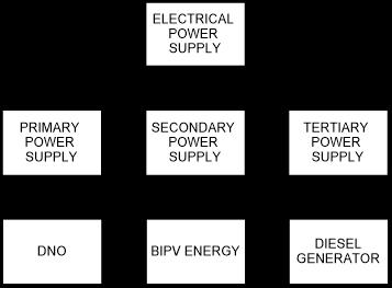
1. PRIMARY POWER SUPPLY – DNO
o PROVIDED BY WESTERN POWER DISTRIBUTION.
o HV ENERGY, THUS CONNECTING THE HOSPITAL TO THE PES.
o STEPPED DOWN TO 230V BY OIL FILLED TRANSFORMER.
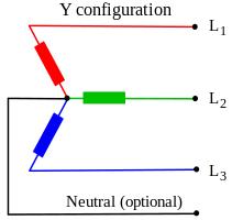
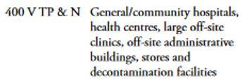
o 3 PHASE AND NEUTRAL (as per HTM 06-01)
OIL FILLED
CAST RESIN
ECONOMICALLY PRICED 30% MORE EXPENSIVE UPFRONT 6-8 WEEK DELIVERY 20-26 WEEK DELIVERY
VENTILATION, LEAKAGE AND FIRE ISSUES* DOESN’T COPE WELL WITH LOAD VARIATIONS
*UNLESS A MORE EXPENSIVE SYNTHETIC (MIDEL) OIL IS USED.
(CAST RESIN IS NOT SUPPORTED BY DNOs)
2.
SECONDARY POWER – BIPV
o BIPV TECHNOLOGY INTEGRATED INTO GLAZING.
o GENERATED POWER STORED IN LI-O BATTERIES (OVER LEAD ACID).
3. TERTIARY POWER – DIELSEL GENERATOR
o 550kVA/420kVA (PEAK/STANDBY) CUMMINS ENGINE DG.
o LOW NOISE ON STANDBY
4. UPS
o 3 PHASE, GIVING GREATER POWER DENSITY WITH SAME AMPERAGE AS ONE-PHASE.
o 550kVA/420kVA (PEAK/STANDBY) CUMMINS ENGINE DG.
o LOW NOISE ON STANDBY
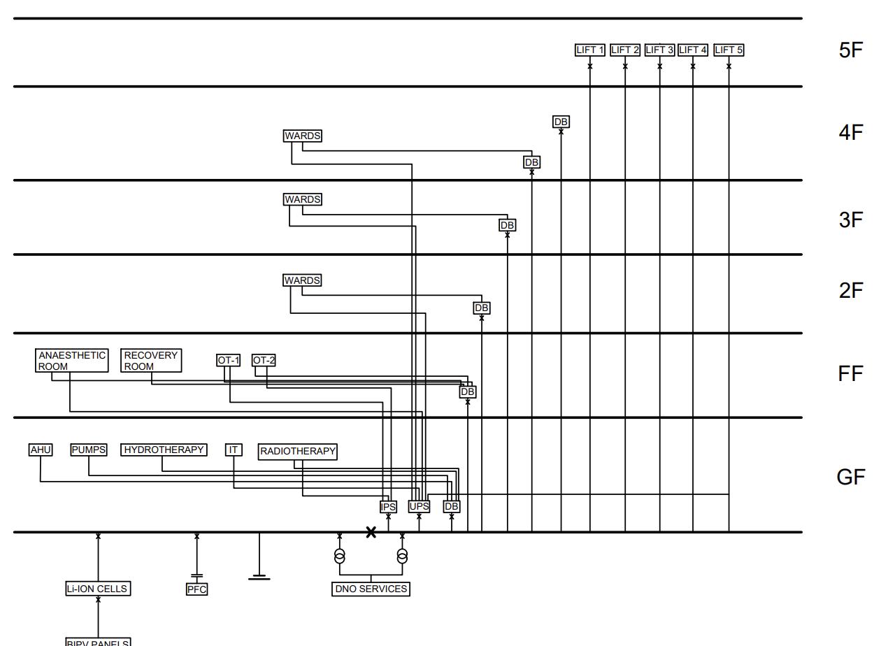
o 3 PHASE, GIVING GREATER POWER DENSITY WITH SAME AMPERAGE AS ONE-PHASE. ELECTRICAL POWER SUPPLY BRANCHING
(Note: Refer shared drive folder for detailed report)
ELECTRICAL DISTRIBUTION DIAGRAM
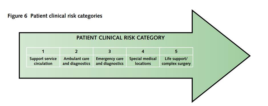
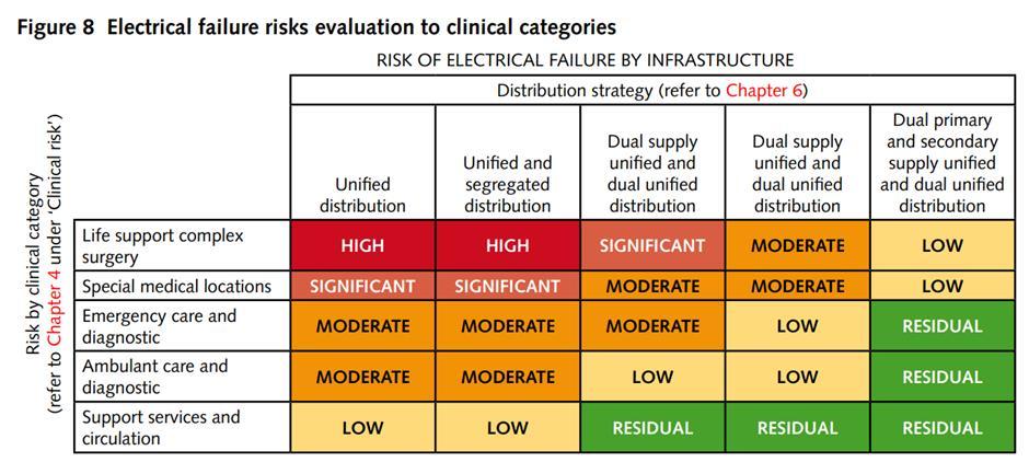
RISK EVALUATION : SOURCE : HTM 06 - 01
(Note: Refer shared drive folder for detailed report)
Mechanical Plant Room
Plant room-4 Air Handling Unit (on roof top)
• Heatpumps ( Connected to underground water)
• Boilers
• Manifolds Water tank
Service room locations:
• Diesel generator 500kW
• Boiler (gas fired)
• Chiller
• Generator Room
(Note: Refer shared drive folder for detailed report)
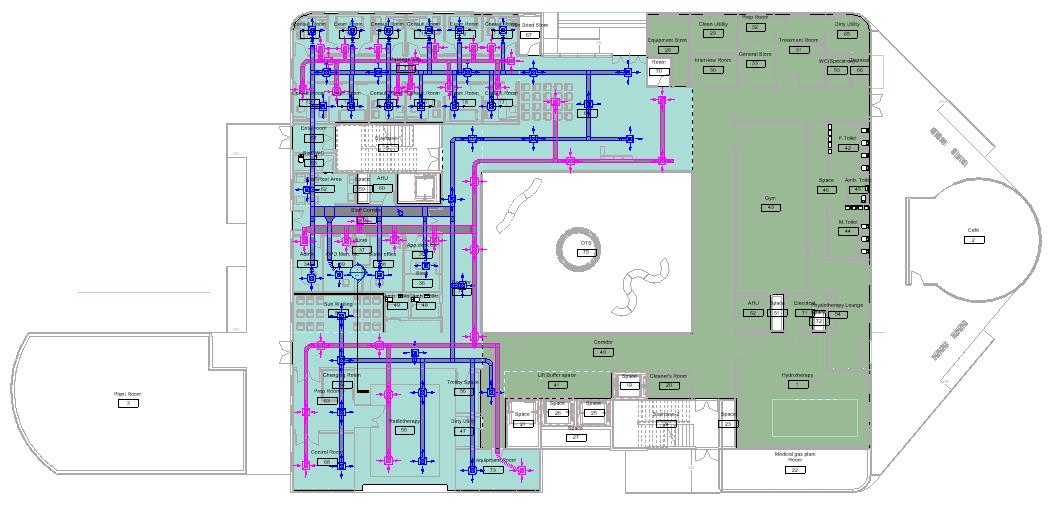
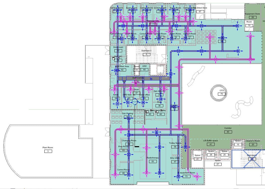
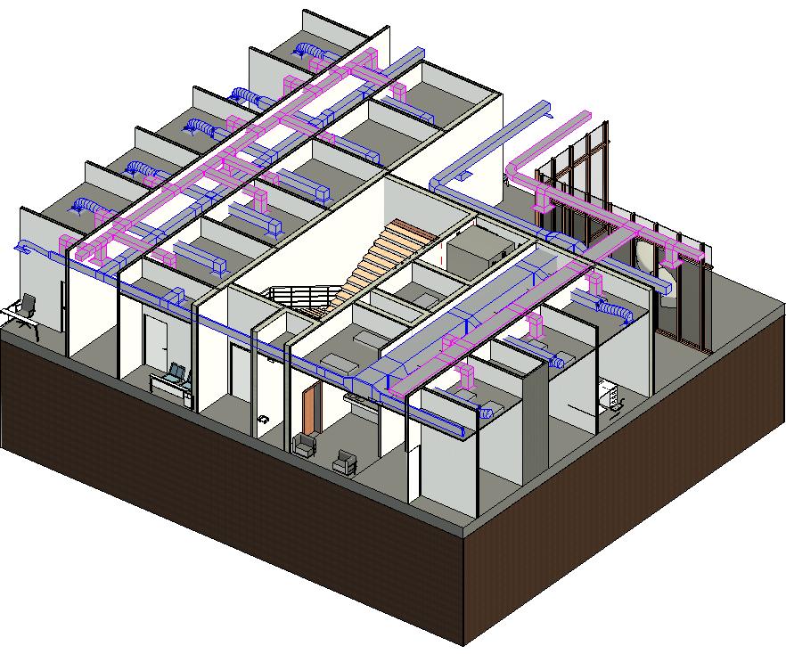
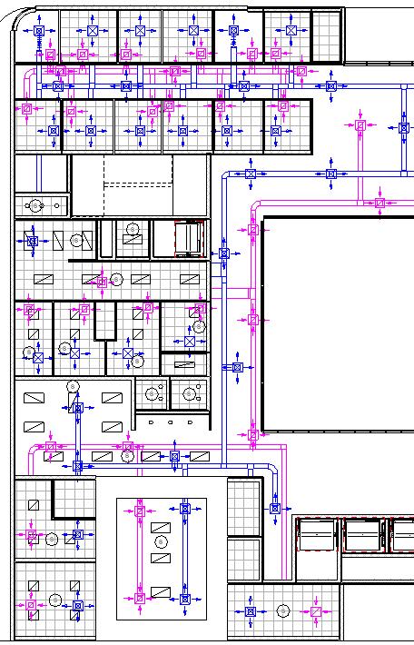
HVAC Equipment:
Plant room-4 Air Handling Unit (on roof top)
• Supply duct system
• Return Duct system
• Extarctors
• Fan coil unit for hydrotherapy
(Note: Refer shared drive folder for detailed report)
Medical gas Plant shaft
(Note: Refer shared drive folder for detailed report) Medical gas plant room Medical Gas Plant: Medical gas plant is isolated from
Plant Room
Medical
VIE plant
(Note: Refer shared drive folder for detailed report)
(Note: Refer shared drive folder for detailed report)
Software: Revit + Sketchup + Lumion
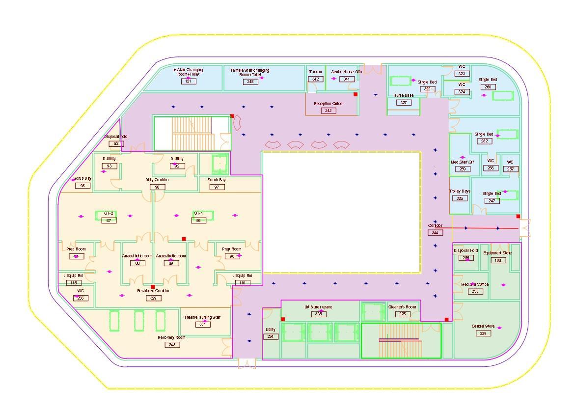
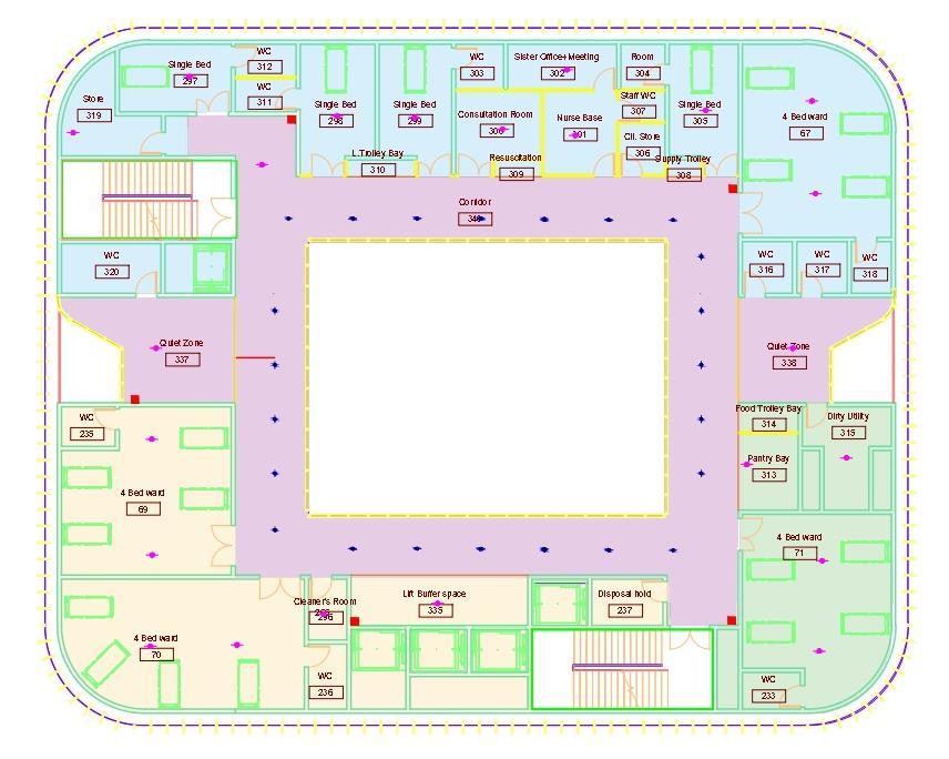
•3 access point provided for Fire and Rescue Services
•3 Fire Assembly Points
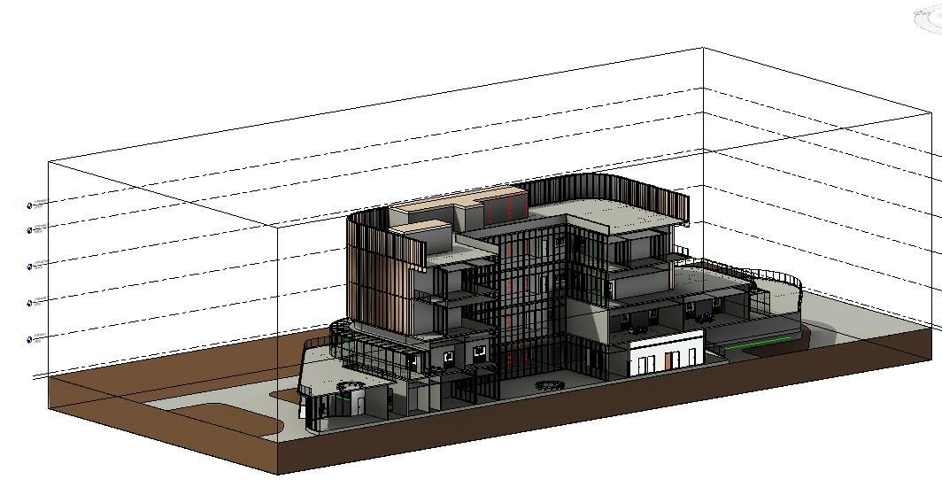
Initially, the team started with the central model integration but because of technical issues among the team members, we made it federated and combined the final.
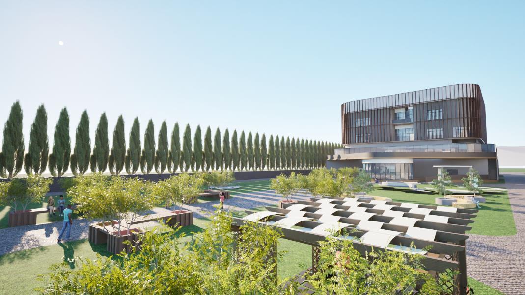
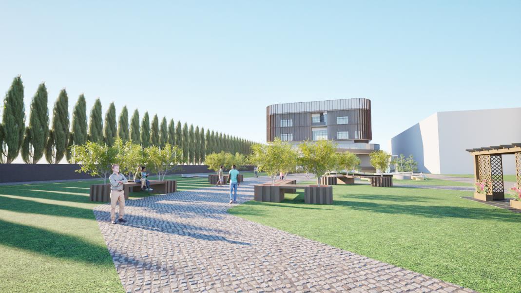
FEDERATED MODEL, 3D MODELLING, PLANNING AND RENDERING
COMMUNICATION AND FILE EXCHANGING
1.Use of BIPV panels in the Façade
2.Natural ventilation & daylight “ Light shelf “
4.Waste management
Proper waste distribution & management
3. Water conservation
Rainwater is collected in a sump and recycled.
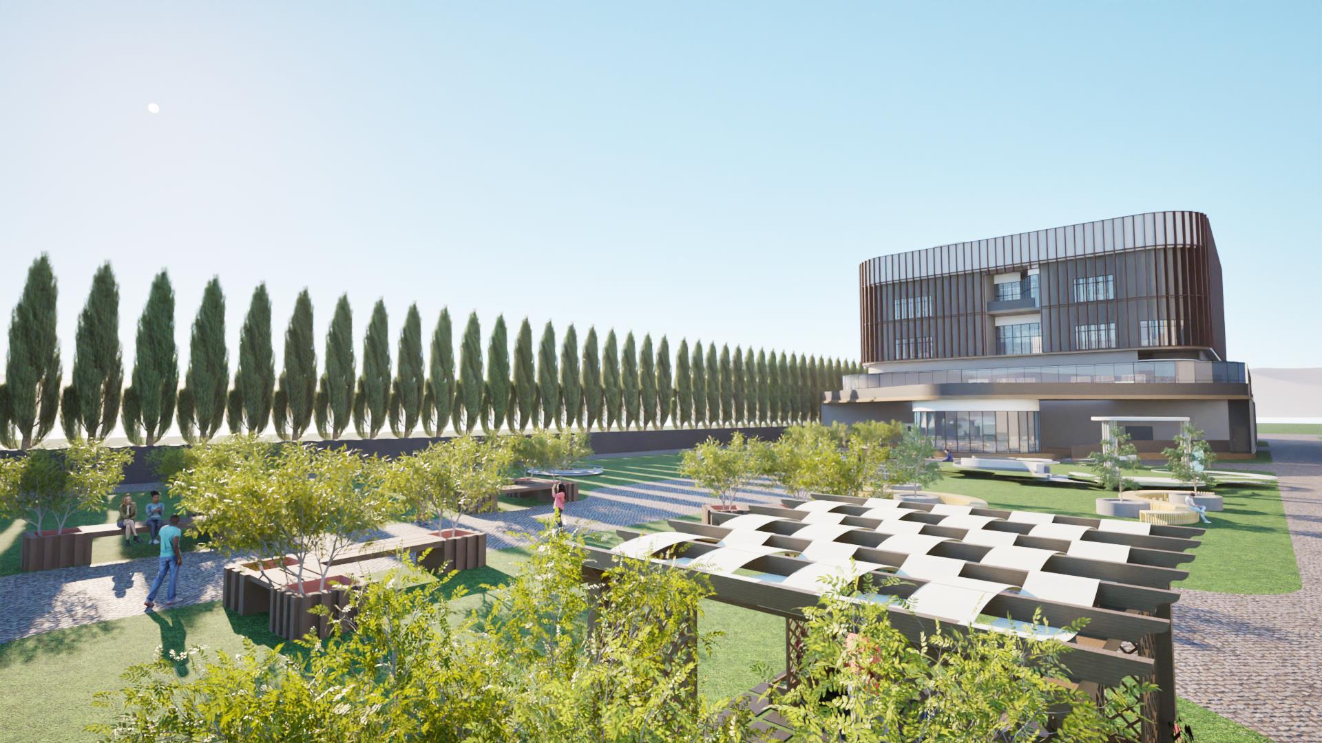
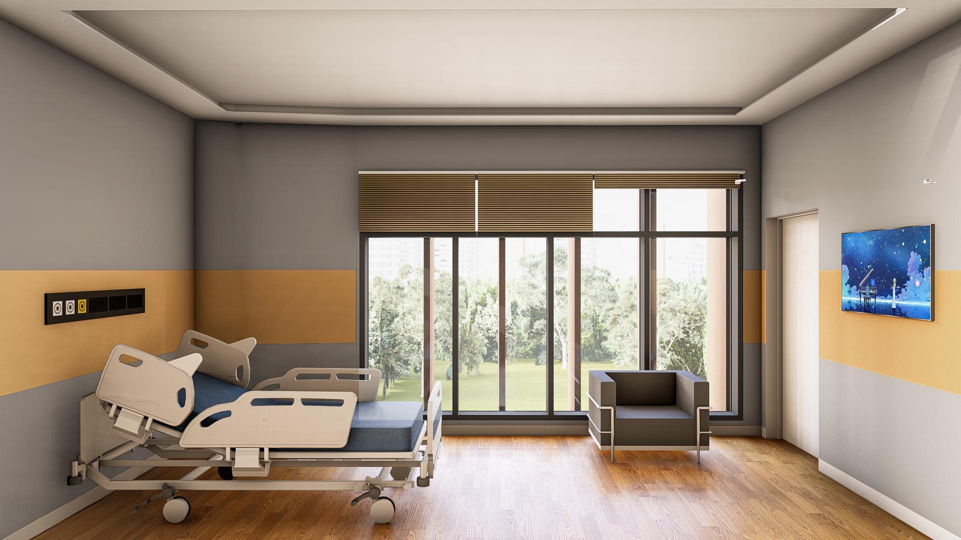
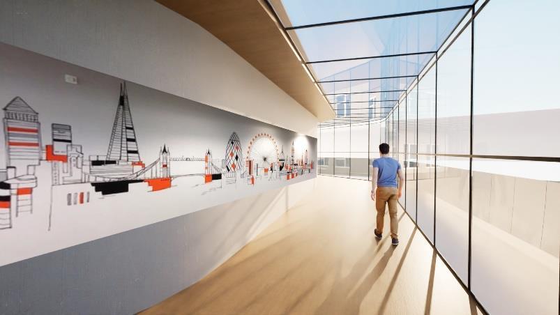
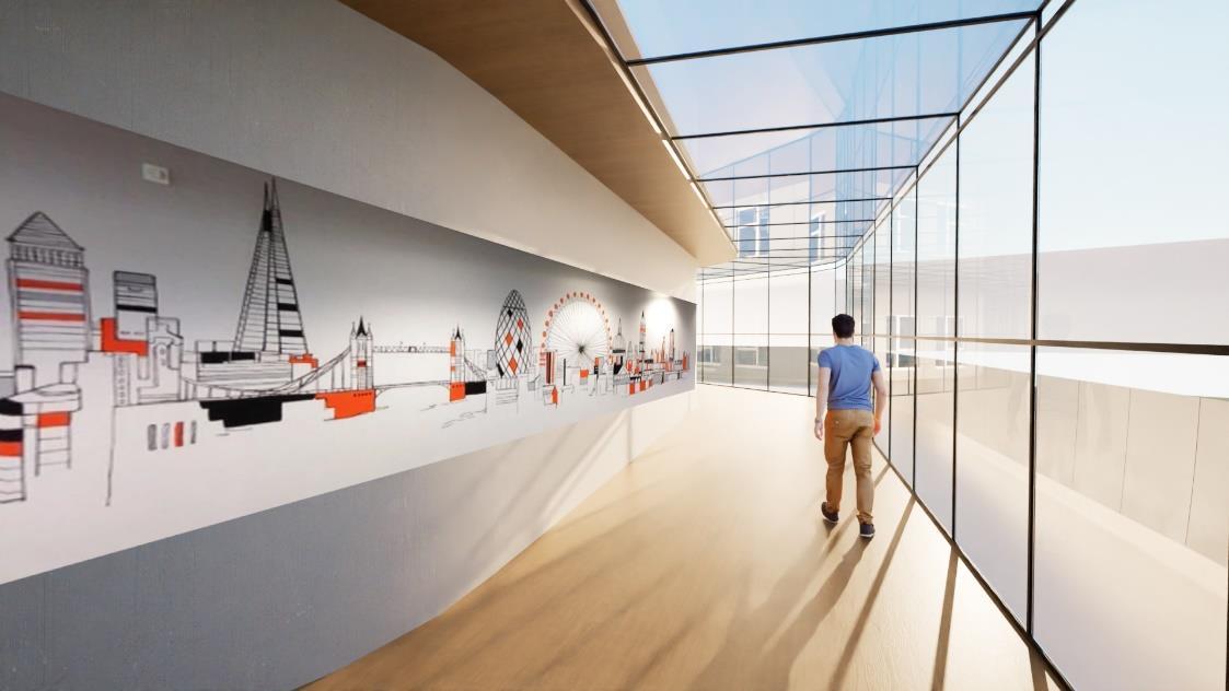
5.Healing & therapeutic spaces
Distribution of indoor & outdoor spaces to enhance the mental health of the patients for fast recovery
6. Central open courtyard
Distribution of indoor & outdoor spaces to enhance the mental health of the patients for speed recovery
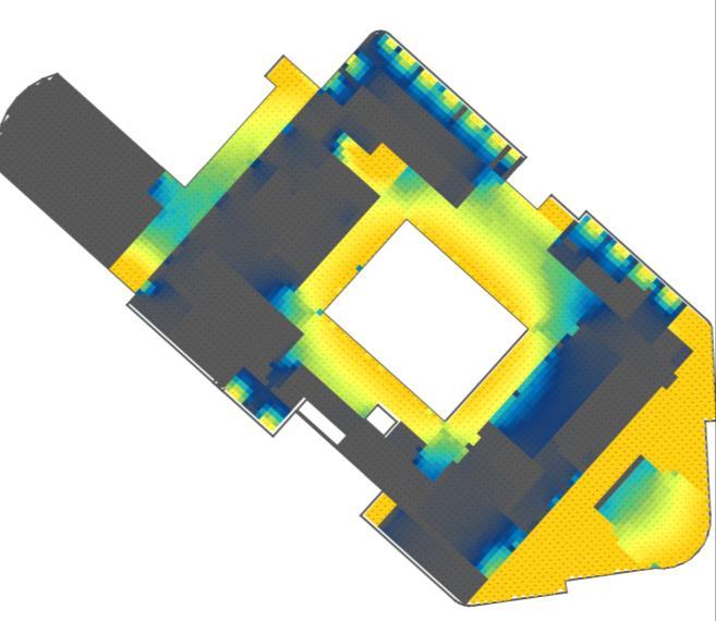
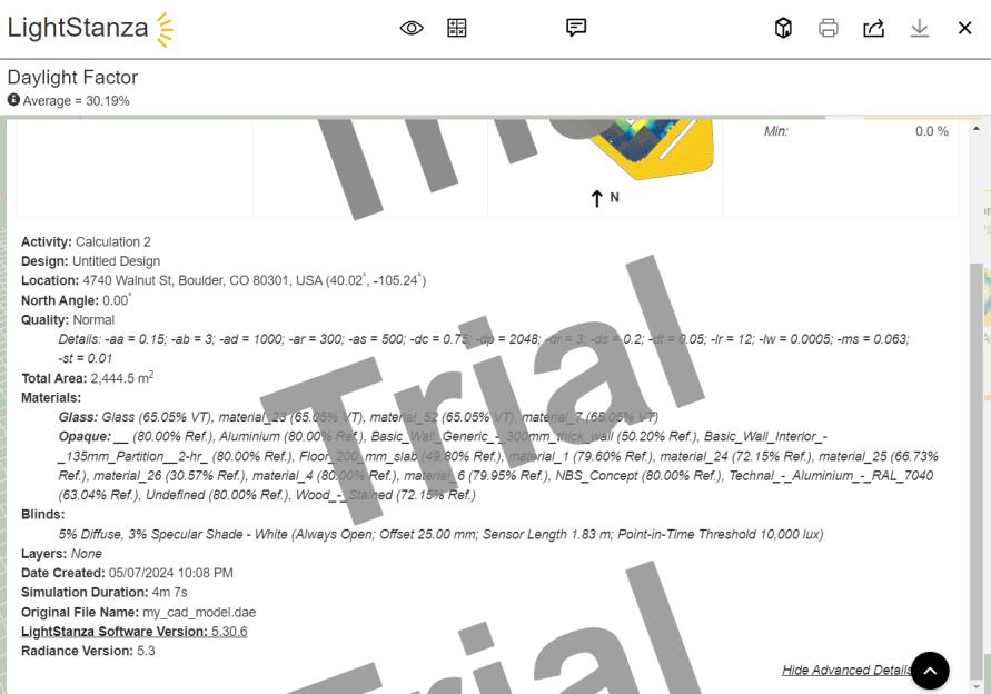
Light stanza report sample - First floor
A light shelf extends the reach of natural sunlight deeper into the building, reducing the need for artificial lighting and contributing to energy efficiency.
Integration formats :
Revit - Base Model
Sketchup - Floor-wise editing
Light stanza - Day Light Analysis
Floor
First Floor
Second Floor
Third Floor
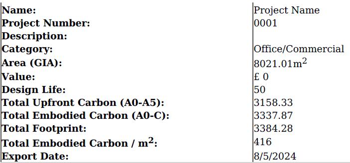
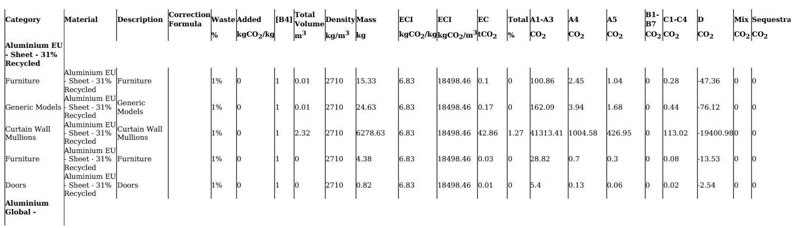
Project Info:
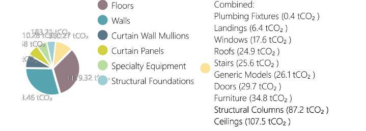
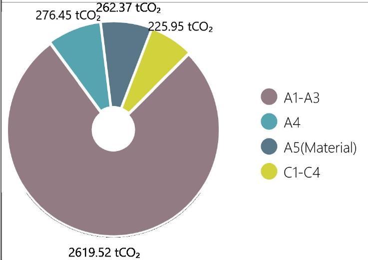
Graphs:
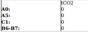
Calculations:
Material Based Values:
Global Values:
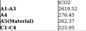
Embodied Carbon Calculation groups:
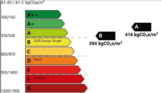
The Upfront Carbon Footprint (A0-A5) is: 3.158.33 tCO2/m²
The Embodied Carbon Footprint (A0-C & Seq) is: 3.337.87 tCO2/m²
The calculated value equals 2417.34 average car emissions per year (1.40 tCO2/car). (UK)
This requires 135371 trees (Spruce or Fir) to grow for at least 30 years
The Social Carbon Cost (SCC) of this project is: £ 507.642.00 Between now and 2100 this will likely cause the death of 763 people.
(Note: Refer shared drive folder for detailed report)
BIPV Panels and Temperature Control
• BIPV Panels
Building-Integrated Photovoltaic (BIPV) panels generate solar energy for the building. They are part of the building's structure, providing a sustainable energy source.
• IoT and BIM Integration
IoT devices monitor temperature throughout the building. Building Information Modeling (BIM) helps manage and visualize data.
Managing Heat with Suction Vents
• Temperature Control
IoT devices detect high temperatures in specific areas. Suction vents transfer excess heat to other parts of the building.
• Energy Efficiency By redistributing heat, the system reduces the need for additional heating.
This approach improves energy efficiency and sustainability.
Benefits and Conclusion
• Energy Efficiency
BIPV panels and IoT-based temperature control reduce energy usage.
Sustainable practices lower the building's carbon footprint.
The combination of BIPV panels, IoT, and BIM offers an efficient way to manage energy and temperature. This system provides comfort and contributes to a greener future.
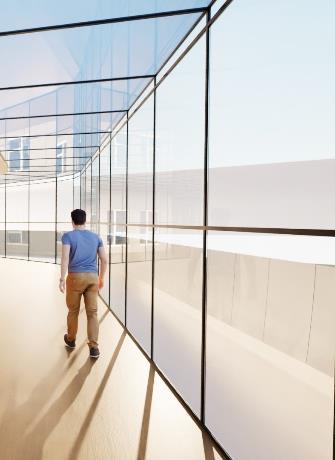
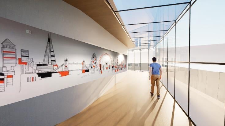
Indoor walking corridor
Quiet zones placed equally in every floor
Central courtyard
Indoor walking / Jogging track
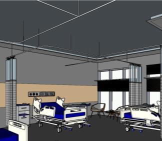
Well Light patient Rooms planned for speed recovery
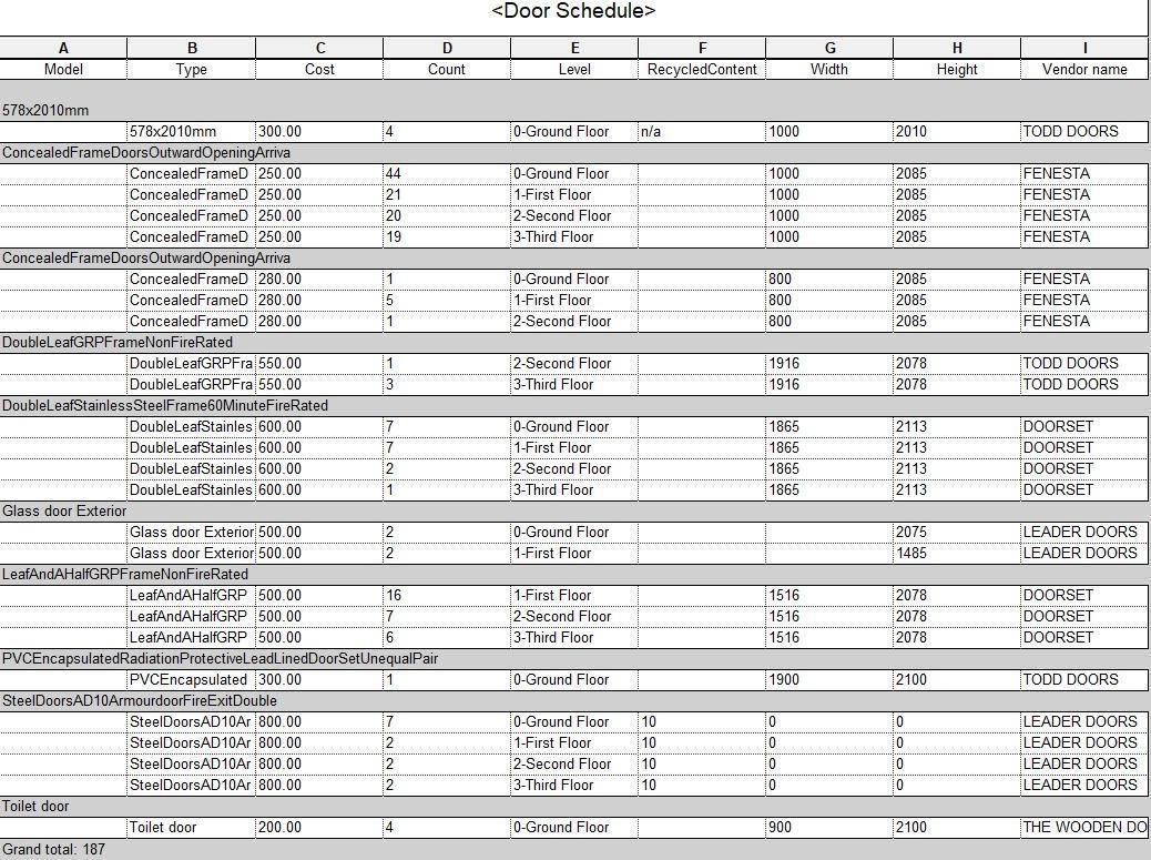
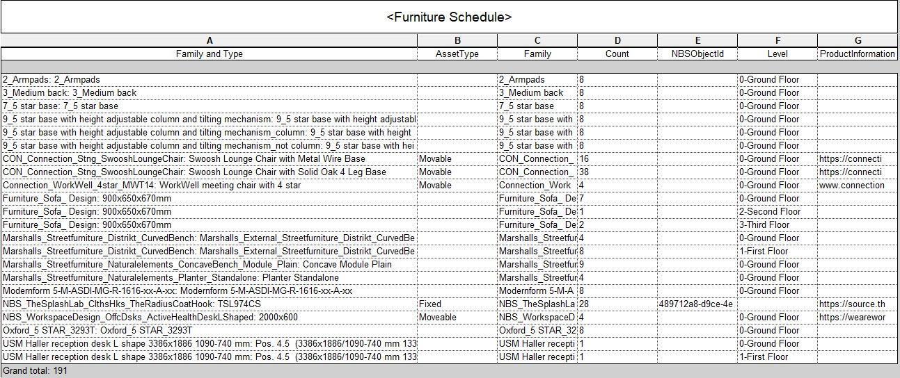
Note: A door costing sample has been created based on the basic criteria available default in the Revit.
THANK YOU !