Manufactory Wholesale Outdoor CATV Optical Node with Excellent AGC Performance for HFC Networks

Page 1


Manufactory Wholesale Outdoor CATV Optical Node with

Excellent AGC Performance for HFC Networks

Struggling with signal stability in harsh outdoor environments? The Outdoor CATV Optical Node delivers exceptional performance with its advanced GaAs amplifier technology and optimized circuit design. Designed for HFC networks, it ensures smooth photoelectric signal transmission and stable output levels even with input optical power ranging from -9 to +2dBm. Ideal for CATV systems, this node features microprocessor control, LCD parameter display, and a data communication interface for seamless network management.

• High response PIN photoelectric conversion tube | • GaAs amplifier for high gain and low distortion | • Excellent AGC performance | • Microprocessor control with LCD display | • Data communication interface for network management

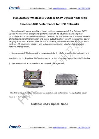
This 1 GHZ 2 output outdoor optical node has Excellent AGC performance. The input optical power range is 9~+2dBm.

Outdoor CATV Optical Node

SR1012ST is our latest high-grade two-output outdoor CATV optical node. The pre-amplifier adopts full-GaAs MMIC, and the post-amplifier adopts GaAs module. Optimized circuit design, coupled with our 10 years professional design experience, makes the equipment achieve good performance indexes. Microprocessor control, digital display the parameters, the engineering debug is especially easy.

Performance Characteristics

High response PIN photoelectric conversion tube.

Optimized circuit design, with SMT process production, optimized signal path, makes the photoelectric signal transmission more smooth.

Specialized RF attenuation chip, with good RF attenuation and equilibrium linear, high accuracy.

GaAs amplifier device, power doubler output, with high gain and low distortion.

Single Chip Microcomputer (SCM) control equipment working, LCD display the parameters, convenience and intuitive operation, and stable performance.

Excellent AGC performance, when the input optical power range is 9~+2dBm, the output level keep unchanged, CTB and CSO basically unchanged.

Reserved data communication interface, can connect with the Ethernet transponder, access to network management system.

Return emission can select burst mode to sharply decrease the noise convergence and reduce the forepart receiver number.

Technique Parameter

Item Unit

Forward optical receiving part

Optical Parameters

Receiving Optical Power dBm -9 ~ +2

Optical Return Loss dB >45

Optical Receiving Wavelength nm 1100 ~ 1600

Optical Connector Type FC/APC, SC/APC or specified by the user

Fiber Type Single Mode

Link Performance

C/N

C/CTB

C/CSO

RF Parameters

Frequency

51 (-2dBm input)

~1000 Flatness in Band

Rated Output Level

Max Output Level dBμV

Output Return Loss dB (45 ~550MHz)≥16/(550~1000MHz)≥14

Output Impedance Ω 75 75

Electronic Control EQ

Electronic Control

Return Optical Emission Part

Optical Parameters

Optical Transmit Wavelength nm 1310±10, 1550±10 or specified by the user

Output Optical Power mW

1, 2

Optical Connector Type

RF Parameters

FC/APC, SC/APC or specified by the user

Frequency Range MHz 5 ~ 65 (or specified by the user)

Flatness in Band dB ±1

Input Level dBμV 72 ~ 85

Output Impedance Ω 75

NPR Dynamic Range dB ≥15 (NPR≥30 dB)

Use DFB laser ≥10 (NPR≥30 dB)

Use FP laser

General Performance

Supply Voltage V A: AC (150~265)V; B: AC (35~90)V

Operating Temperature ℃ -40~60

Storage Temperature ℃ -40~65

Relative Humidity % Max 95% no condensation

Consumption VA ≤ 22

Dimension mm 260

Common Failure Analysis and Troubleshooting

Failure phenomenon Failure cause Solution

After connecting the network, the image o f the optical contact point has obvious netlike curve or large particles highlig hts but the image backg

1. The input optical power of the optical receiver is too high, make the output level of the optical receiver module too high and RF signal index deteriorate.

2. The RF signal (input the

1. Check the input optical power and make appropriate adjustments to make it in the specified range; or adjust the attenuation of optical receiver to reduce the output level and improve index.

2. Check the front end machine room

Contact:Tomleequan Email:sales@fmuser.com whatsapp: +8613922702227

round is clean.

optical transmitter) index is poor. optical transmitter RF signal index and make appropriate adjustments.

After connecting the network, the image of the optical contact point has obvious noises.

1. The input optical power of the optical receiver is not high enough, results in the decrease of C/N.

2. The optical fiber active connector or adapter of the optical receiver has been polluted.

3. The RF signal level input the optical transmitter is too low, make modulation degree of the laser is not enough.

4. The C/N index of system link signal is too low.

1. Check the received optical power of the optical contact point and make appropriate adjustments to make it in the specified range.

2. Recover the received optical power of the optical contact point by cleaning the optical fiber connector or adapter etc methods.

Specific operation methods see “Clean and maintenance method of the optical fiber active connector”.

3. Check the RF signal level input the optical transmitter and adjust to the required input range. (When the input channels number less than 15, should higher than nominal value.)

4. Use a spectrum analyzer to check the

Contact:Tomleequan Email:sales@fmuser.com whatsapp: +8613922702227

After connecting the network, the images of several optical contact points randomly appear obvious noises or bright traces. The optical contact point has open circuit signal interference or s trong interference signal intrusion.

system link C/N and make appropriate adjustments. Make sure the system link signal C/N﹥51dB.

1. Check if there is strong interference signal source; change the optical contact point location if possible to avoid the influence of strong interference signal source.

2. Check the cable lines of the optical contact point, if there is shielding net or situation that the RF connector shielding effect is not good.

3. Tightly closed the equipment enclosure to ensure the shielding effect; if possible add shielding cover to the optical contact point and reliable grounding. After connecting the network, the images of Power supply AC ripple interference because of the bad earth of Check grounding situation of the equipment, make sure that every equipment in the

several optical contact points appear one or two horizontal bright traces. equipment or power supply. line has been reliably grounding and the grounding resistance is﹤4Ω.

After connecting the network, the received optical power of the optical contact point is unstable and has large continuous change. The output RF signal is unstable, too. But the detected output optical power of the optical transmitter is normal.

The optical fiber active connector types do not match, maybe the APC

type connect to PC type, make the optical signal cannot normal transmission.

The optical fiber active connector or adapter may be polluted seriously or the adapter has been damaged.

1. Check the type of optical fiber active connector and adopt the APC type optical fiber active connector to ensure the normal transmission of optical signal.

2. Clean the polluted optical fiber active connector or adapter. Specific operation methods see “Clean and maintenance method of the optical fiber active connector”.

3. Replace the damaged adapter.

About Us

FMUSER is a company specializing in broadcasting and television transmission systems and integrating hotel IPTV systems. The company was established in 2009 and has served over 180 countries worldwide. More than 20,000 television stations, radio stations, and hotel clients from different.

Turn static files into dynamic content formats.

Create a flipbook
Issuu converts static files into: digital portfolios, online yearbooks, online catalogs, digital photo albums and more. Sign up and create your flipbook.