

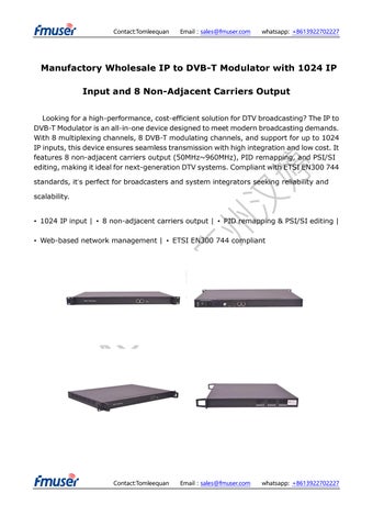
Manufactory Wholesale IP to DVB-T Modulator with 1024 IP
Input and 8 Non-Adjacent Carriers Output
Looking for a high-performance, cost-efficient solution for DTV broadcasting? The IP to DVB-T Modulator is an all-in-one device designed to meet modern broadcasting demands. With 8 multiplexing channels, 8 DVB-T modulating channels, and support for up to 1024 IP inputs, this device ensures seamless transmission with high integration and low cost. It features 8 non-adjacent carriers output (50MHz~960MHz), PID remapping, and PSI/SI editing, making it ideal for next-generation DTV systems. Compliant with ETSI EN300 744 standards, it’s perfect for broadcasters and system integrators seeking reliability and scalability.
• 1024 IP input | • 8 non-adjacent carriers output | • PID remapping & PSI/SI editing |
• Web-based network management | • ETSI EN300 744 compliant


to dvb-t modulator is an all-in-one device developed by us.
to dvb-t modulator

IP to DVB-T modulator is an all-in-one device developed by us. It has 8 multiplexing channels and 8 DVB-T modulating channels, and supports maximum 1024 IP input through the GE port and 8 non-adjacent carriers (50MHz~960MHz) output through the RF output interface. The device is also characterized with high integrated level, high performance and low cost. This is very adaptable to newly generation DTV broadcasting system.

Contact:Tomleequan Email:sales@fmuser.com whatsapp: +8613922702227
IP
IP

FEATURES of IP to DVB-T modulator
2 GE input, SFP interface
Supports up to 1024 channels TS over UDP/RTP, unicast and multicast, IGMP v2\v3
Max 840Mbps for each GE input
Supports accurate PCR adjusting
Supports PID remapping and PSI/SI editing
Supports up to 180 PIDS remapping per channel
Support 8 multiplexed TS over UDP/RTP/RTSP output
8 DVB-T non-adjacent carriers output, compliant to ETSI EN300 744 standard
Supports RS (204,188) encoding
Support Web-based Network management
Specification of IP to DVB-T modulator
Input
Input
Transport Protocol
Transmission Rate
Mux
512×2 IP input, 2 100/1000M Ethernet Port (SFP)
TS over UDP/RTP, unicast and m ulticast, IGMP V2/V3
Max 840Mbps for each input cha nnel
Input Channel 1024
Output Channel 8
Max PIDs 180 per channel Functions
PID remapping(auto/manually opti onal)
PCR accurate adjusting
PSI/SI table automatically generat

Contact:Tomleequan

Modul ation
Param eters
Channel 8
Modulation Standard ETSI EN300 744
Constellation QPSK/16QAM/64QAM
Bandwidth 6/7/8 MHz
Trans mode
2K/4K/8K
FEC 1/2, 2/3, 3/4, 5/6, 7/8
RF Outpu t Interface
RF Range
Output Level
F typed output port for 8 non-adjacent carriers
50~960MHz, 1kHz stepping
-20~+10dbm (for all carriers), 0.5 db stepping
MER ≥ 40dB
ACL -55 dBc
TS output 8 IP output over UDP/RTP/RTSP, unicast/multicast, 2 100/1000M Ethernet Ports
Syste m Web-based Network management
Environment requirement
Item Requirement
Machine Hall Space
Machine Hall Floor
When user installs machine frame array in one machine hall, the distance between 2 rows of machine frames should be 1.2~1.5m and the distance against wall should be no less than 0.8m.
Electric Isolation, Dust Free
Volume resistivity of ground anti-static material: 1X10⁷~1X10¹⁰W, Grounding current limiting resistance: 1M (Floor bearing should be greater than 450Kg/㎡)


Environm ent Temperat
ure
Relative Humidity
5~40℃(sustainable ), 0~45℃(short time)
installing air-conditioning is recommended
20%~80% sustainable 10%~90% short time
Pressure 86~105KPa
Door & Window
Installing rubber strip for sealing door-gaps and dual level glasses for window
Wall It can be covered with wallpaper, or brightness less paint.
Fire Protection Fire alarm system and extinguisher
Power
Requiring device power, air-conditioning power and lighting power are independent to each other. Device power requires AC power 220V ±10% 50/60Hz or 110V ±10% 50/60Hz. Please carefully check before running.
Grounding Requirement
All function modules’ good grounding is the basis of reliability and stability of devices. Also, they are the most important guarantee of lightning arresting and interference rejection. Therefore, the system must follow this rule.
Coaxial cables’ outer conductor and isolation layer should keep proper electric conducting with the metal housing of device.
Grounding conductor must adopt copper conductor in order to reduce high frequency impedance, and the grounding wire must be as thick and short as possible.
Users should make sure the 2 ends of grounding wire well electric conducted and be antirust.
It is prohibited to use any other device as part of grounding electric circuit
The area of the conduction between grounding wire and device’s frame should be no less than 25mm2.
About Us
FMUSER is a company specializing in broadcasting and television transmission systems and integrating hotel IPTV systems. The company was established in

Contact:Tomleequan Email:sales@fmuser.com whatsapp: +8613922702227

