
ServiceTraining Meeting Guide 621 SESV1621 August 1992 TECHNICALPRESENTATION 320/330HYDRAULICEXCAVATORS ELECTRONICCONTROLUNIT Caterpillar 320 330 Hydraulic Excavator Electronic Control Unit Full download: http://manualplace.com/download/caterpillar-320-330-hydraulic-excavator-electronic-control-unit/ This is the cut pages sample. Download all 94 page(s) at: ManualPlace.com
AUDIENCE
Level II - Service personnel who understand the principles of machine systems operation, diagnostic equipment, and procedures for testing and adjusting.
CONTENT
This presentation contains the information and visuals necessary to develop a Level II course of instruction on the Electronic Control Unit (ECU) for the 320, 320L, 320N, 330, and 330L Hydraulic Excavators. Emphasis is placed on explaining how the ECU and Monitor Panel function. The Data and Calibration Modes of the system are also explained in detail.
OBJECTIVES
After learning the information in this presentation, the serviceman will be able to: 1. locate and identify the major components of the ECU and monitor panel system; 2. identify all input and output signals for the ECU and monitor panel; 3. explain the function and operation of each major component; and 4. explain and demonstrate how to access the built-in diagnostic procedures.
REFERENCES
320, 320L and 320N Excavators Service Manual (3116 Engine with Bent Axis Pump)SENR5450
320, 320L and 320N Excavators Service Manual (3066 Engine with Swashplate Pump)SENR5465
320, 320L and 320N Excavators Hydraulic and Electronic Systems Testing and AdjustingSENR5473 320, 320L and 320N Excavators Parts BookSEBP2034 330 and 330L Excavators Service ManualSENR5490 330 and 330L Excavators Hydraulic and Electronic Systems Testing and AdjustingSENR5496 330 and 330L Excavators Parts BookSEBP2171
PREREQUISITES
320/330HYDRAULICEXCAVATORS
ELECTRONICCONTROLUNIT MEETINGGUIDE621SLIDESANDSCRIPT
Cat Hydraulics Course (or equivalent)SEGV2519 STMG 546 "Graphic Fluid Power Symbols"SESV1546 STMG 584 "Electronic Power Unit Control for E-Series Hydraulic Excavators"SESV1584 SUPPLEMENTARYTRAININGMATERIAL STMG 619 "320/330 Hydraulic Excavator--Pumps and Pump Controls"SESV1619 STMG 620 "320/330 Hydraulic Excavator--Hydraulic Systems Operation"SESV1620 Estimated Time: 3 Hours Visuals: 58 (2 X 2) Slides Serviceman Handouts: 4 line drawings Form:
Date: 8/92 ©1992CaterpillarInc.
SESV1621
STMG621-38/92 TABLEOFCONTENTS INTRODUCTION........................................................................................................................5
Location and Function.........................................................................................6
Width Modulated Signals............................................................................................13 Controller Changes...............................................................................................................14 Monitor Features...................................................................................................................16
Input Components...............................................................................................17
Output Components.............................................................................................19
Mode Selection..........................................................................................................21
Dial Limits.................................................................................................................36 SYSTEMS OPERATION...........................................................................................................37 320 System Behavior............................................................................................................38 330 System Behavior............................................................................................................40 Power Mode Settings............................................................................................................42 Automatic Engine Control (AEC)........................................................................................47 One-touch Low Idle Control.................................................................................................49 Backup Systems....................................................................................................................50 SERVICE FUNCTIONS.............................................................................................................53 Data Mode.............................................................................................................................54 Calibration Mode..................................................................................................................64 CONCLUSION...........................................................................................................................83 SLIDE LIST................................................................................................................................85 SERVICEMAN'S HANDOUTS.................................................................................................87
Component
Pulse
Controller
Controller
Power
P-Q Curves (320 with 3116 engine and Bent Axis Pump)...................................................22 P-Q Curves (320 with 3066 engine and Swashplate Pump).................................................24 P-Q Curves (330 with 3306 engine).....................................................................................26 P-Q Curves (320 with 3116 engine and Bent Axis Pump)...................................................28 P-Q Curves (320 with 3066 engine and Swashplate Pump).................................................30 P-Q Curve (330 with 3306 engine).......................................................................................32 Pump Regulation...................................................................................................................34 Speed
INSTRUCTORNOTES
STMG621-48/92
• Electronic Control Unit (ECU) also called "controller"
• Matches hydraulic horsepower to engine horsepower
• Receives, processes, and sends signals
• Warns of machine problems
• Varies pump flow rates
• Provides diagnostics
INTRODUCTION
1
This presentation introduces the Electronic Control Unit (ECU) used on the Caterpillar 320 and 330 Hydraulic Excavators. These ECU's are referred to as "controllers" because they match hydraulic horsepower to engine horsepower by controlling engine rpm.
The controller receives input signals from the engine, the hydraulic system and the operator. As operating conditions change, the controller sends output signals to change engine speed, warn the operator of potential problems and to vary the hydraulic pump flow rate.
This presentation will explain the major differences between the 320/330 controller and those used on the "E" series hydraulic excavators. The ways in which this controller simplifies machine operation and diagnostics for both operators and servicemen will also be discussed.
STMG621-58/92
332200//333300 H H Y Y D D R R A A U U II C C E E X X C C A A V V A A T T O O R R
E E L L E E C C T T R R O O N N II C C C C O O N N T T R R O O L L U U N N II T T
©1992CaterpillarInc.
• Controller located outside the cab
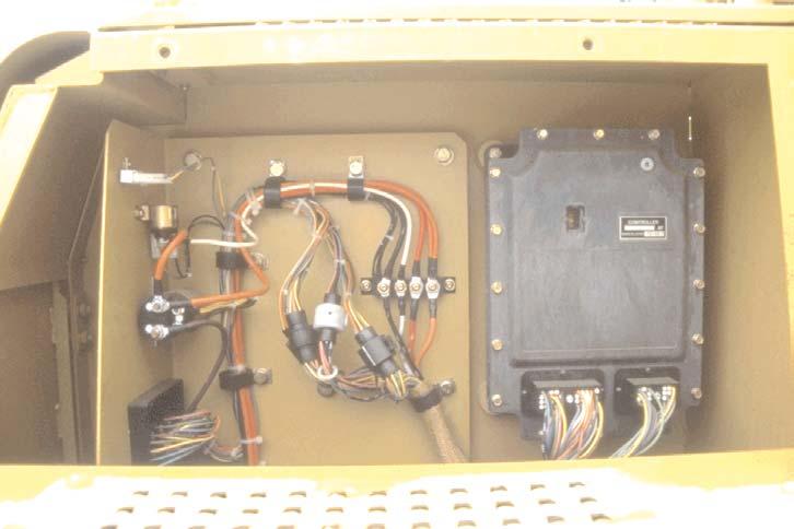
• Totally sealed unit
•3 LED's (arrow) for some diagnostics
2
ComponentLocationandFunction
The controller is located in an outside compartment above and behind the battery box. A panel must be removed to access the controller. The controller is a totally sealed unit like the transmission controls for Caterpillar Off-highway Trucks and Wheel Tractor-Scrapers. The only time when removal of the compartment cover will be necessary is when the monitor panel on the operator's console in the cab shows the controller fault symbol or when the diagnostic error codes indicate that the three diagnostic Light Emitting Diodes (LED's - arrow) need to be checked. The fault symbols and error codes will be discussed in detail later in this presentation.
STMG621-68/92
3
•If controller fault symbol stays ON, check the LED's
• Yellow LED ON, communication problem with monitor
• Red LED ON steady or flashing, replace CPU
• Green LED ON, normal operation
As mentioned in the previous slide, if the controller fault symbol on the monitor panel comes ON and stays ON, a problem in the controller system is indicated. The three diagnostic LED's on the controller will provide an indication of the problem.
When the yellow LED turns ON, a communication problem with the monitor is indicated.
If the red LED is ON (steady or flashing), the Central Processor Unit (CPU) is not functioning correctly and must be replaced.
During engine start-up, the three LED's will briefly illuminate. The red and yellow LED's will quickly turn OFF leaving just the green LED ON, which indicates normal operation.

STMG621-78/92
4
• Monitor panel: - Push buttons activate many functions
- Displays information
• Engine speed dial: - Ten positions
- Replaces governor control lever
The operator's console has a monitor panel that permits several machine functions to be activated with push buttons. The monitor panel also displays information about the machine operating status and diagnostic information.
The machine is equipped with an engine speed dial that has ten different positions. This digital rotary switch replaces the governor control lever which was used in earlier hydraulic excavators. The engine speed dial will also be discussed in detail later in this presentation.

STMG621-88/92
Full download: http://manualplace.com/download/caterpillar-320-330-hydraulic-excavator-electronic-control-unit/
• Two backup systems:
- Engine speed dial (two switches)
- Pump control (one switch)
• Speed dial rear switch:
- Normally run in "AUT" position
- Dial disconnected in "MAN" position
• Speed dial front switch: - "Rabbit" position increases rpm - "Tortoise" position decreases rpm
• Pump control switch: - Normally run in "AUT" position - "Tortoise" position connects PRV to backup resistor
5
Two backup systems are provided to prevent machine down situations. One backup system is for the engine speed dial and the second is for the pump controls. Each system is activated by toggle switches at the rear of the operator's seat arm consoles.
The engine speed dial circuit (shown) has two backup switches on the right console. The rear switch is normally run in the "AUT" position. When the switch is moved to the "MAN" position, the engine speed dial signal is disconnected from the controller. The front switch is then used to manually control the engine speed. Push the front switch toward the "Rabbit" to increase engine speed or toward the "Tortoise" to decrease engine speed.
The pump control backup switch (not visible in this view) is the single toggle switch on the left console. The backup switch has two positions-"AUT" and "Tortoise." This switch also is normally run in the "AUT" position. If a pump control problem occurs, move the switch to the "Tortoise" position. The pump control is bypassed and power to the Proportional Reducing Valve (PRV) is supplied through a backup resistor.

STMG621-98/92
Caterpillar 320 330 Hydraulic Excavator Electronic Control Unit
This is the cut pages sample. Download all 94 page(s) at: ManualPlace.com

