Solution Manual for Dynamics of Structures 5th Edition by Chopra ISBN
0134555120
9780134555126
Full download at : https://testbankpack.com/p/solution-manual-for-dynamics-ofstructures-5th-edition-by-chopra-isbn-0134555120-9780134555126/
CHAPTER 2
Problem 2.1

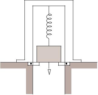
A heavy table is supported by flat steel legs (Fig. P2 1) Its natural period in lateral vibration is 0.5 sec When a 50-lb plate is clamped to its surface, the natural period in lateral vibration is lengthened to 0.75 sec. What are the weight and the lateral stiffness of the table?

Solution:
1 Determine the weight of the table.
Taking the ratio of Eq. (b) to Eq. (a) and squaring the result
2 Determine the lateral stiffness of the table.
Problem 2.2
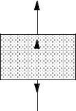
An electromagnet weighing 400 lb and suspended by a spring having a stiffness of 100 lb/in (Fig. P2 2a) lifts 200 lb of iron scrap (Fig. P2 2b) Determine the equation describing the motion when the electric current is turned off and the scrap is dropped (Fig. P2 2c)
Solution:
1 Determine the natural frequency 400
k = 100 lb in m = 386 lb sec 2 in.
ωn = k = 100 = 9 82 rads sec
m 400386
2. Determine initial deflection.
Static deflection due to weight of the iron scrap 200
u(0) = 100 = 2 in
3 Determine free vibration
u(t ) = u(0 ) cos ωnt = 2 cos (9. 82t )
© 2017 Pearson Education, Inc , Hoboken, NJ All rights reserved This material is protected under all copyright laws as thebe reproduced, in any form or by any means, without permission in writing from the publisher
Figure P2.2Problem 2.3
A mass m is at rest, partially supported by a spring and partially by stops (Fig. P2.3). In the posi-tion shown, the spring force is mg/ 2. At time t = 0 the stops are rotated, suddenly releasing the mass. Determine the motion of the mass
Solution:
1 Set up equation of motion
2 Solve equation of motion
u(t ) = A cos ω t + B sin ω t + mg
At t = 0 , u(0) = 0 and u&(0) = 0
∴A= 2 k B = 0
u(t ) = mg (1 cos ωnt )
k
© 2017 Pearson Education, Inc , Hoboken, NJ All rights reserved This material is protected under all copyright laws as thebe reproduced, in any form or by any means, without permission in writing from the publisher
Problem 2.4
The weight of the wooden block shown in Fig. P2 4 is 10 lb and the spring stiffness is 100 lb/in A bullet weighing 0.5 lb is fired at a speed of 60 ft/sec into the block and becomes embedded in the block. Determine the resulting motion u(t) of the block
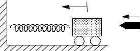

Solution: 10 m = 386 = 0. 0259 lb sec 2 in. 0 5 386 = 1 3 × 10 3 lb sec 2 in
k = 100 lb in.
Conservation of momentum implies & m0v0 = (m + m0 ) u(0)
u& (0) = m 0v 0 = 2 857 ft sec = 34 29 in sec
After the impact the system properties and initial conditions are
Mass= m + m = 0 0272lb sec 2 in 0
Stiffness = k = 100 lb in
Natural frequency:
ωn = k = 60 63radssec m + m0
Initial conditions: u(0) = 0, u&( 0) = 34 29 in sec
The resulting motion is
u(t ) = u&( 0) sin ω t = 0 565 sin (60 63t ) in n
Problem 2.5

A mass m1 hangs from a spring k and is in static equilibrium A second mass m 2 drops through a height h and sticks to m1 without rebound (Fig. P2.5). Determine the subsequent motion u( t) measured from the static equilibrium position of m1 and k
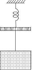

With u measured from the static equilibrium position of
1 and k, the equation of motion after impact is
The initial velocity in Eq (d) was determined by conservationof momentum during impact:
Problem 2.7

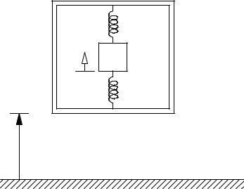
The packaging for an instrument can be modeled as shown in Fig. P2 6, in which the instrument of mass m is restrained by springs of total stiffness k inside a container; m = 10 lb/g and k = 50 lb/in. The container is accidentally dropped from a height of 3 ft above the ground Assuming that it does not bounce on contact, determine the maximum deformation of the packaging within the box and the maximum acceleration of the instrument.
Solution:
1 Determine deformation and velocity at impact.
© 2017 Pearson Education, Inc , Hoboken, NJ All rights reserved
material is protected under all copyright laws as thebe reproduced, in any form or by any means, without permission in writing from the publisher
Problem 2.8
Consider a diver weighing 200 lbs at the end of a diving board that cantilevers out 3 ft. The diver oscillates at a frequency of 2 Hz. What is the flexural rigidity EI of the diving board?
Solution:
Given: 200
m = 32. 2 = 6 211 lb
sec 2 ft fn = 2 Hz
Determine EI: 3 EI
k = L3 3EI = 33 EI = 9 lb ft
f = 1 k ⇒ 2 = 1 EI ⇒
n 2π m 2π 55 90
EI = (4π)2 55.90 = 8827 lb ft2
2017
Show that the motion of a critically damped system due to initial displacement
(0) and initial velocity
Assume a solution of the form u(t ) = e st .
Substituting this solution into Eq (c) yields
Because e st is never zero, the quantity within parentheses must be zero:
The general solution has the following form: u(t ) = A e ω n t + A t e ω n t (d)
where the constants A1 and A2 are to be determined from the initial conditions: u( 0) and u&( 0)
Evaluate Eq (d) at t = 0 : u(0) = A1 ⇒ A1 = u(0) (e)
DifferentiatingEq (d) with respect to t gives
&(t ) = ω A e ω n t +A(1 ω t)e ω n t (f)
Problem 2. 10
Show that the motion of an overcritically damped system due to initial displacement u(0) and initial velocity u (0) is
through by m gives
Assume a solution of the form u(t ) = e st Substituting this solution into Eq. (b) yields
Because e st is never zero, the quantity within parentheses must be zero:
The general solution has the following form:
Problem 2.10
Derive the equation for the displacement response of a viscously damped SDF system due to initial velocity u (0) for three cases: (a) underdamped systems; (b) critically damped systems; and (c) overdamped systems Plot u(t) ÷ u˙(0)/ωn against t/Tn for ζ = 0 1, 1, and 2
Solution:
u& + 2ζω n u& + ω 2 u = 0 (a) n Assume a solution of the form
Substituting A and B into Eq (f) gives
(b) Critically Damped Systems, ζ = 1
The roots of the characteristic equation [Eq (b)] are:
Substituting this solution into Eq. (a) yields:
Because e st is never zero
+ 2ζω 2 s + ω = 0
The roots of this characteristic equation depend on ζ
(a) Underdamped Systems, ζ<1
The two roots of Eq (b) are
Hence the general solution is
which after substituting in Eq (c) becomes
Substituting in Eq (i) gives
(c) Overdamped Systems, ζ>1
The roots of the characteristic equation [Eq (b)] are:
(e) Determined from the initial conditions
Rewrite Eq. (d) in terms of trigonometricfunctions:

Problem 2.11
For a system with damping ratio ζ , determine the number of free vibration cycles required to reduce the displacement amplitude to 10% of the initial amplitude; the initial velocity is zero.
1
Problem 2.12
What is the ratio of successive amplitudes of vibration if the viscous damping ratio is known to be
ζ = 0.01, (b) ζ = 0.05, or (c) ζ = 0.25?
Problem 2.13
The supporting system of the tank of Example 2.6 is enlarged with the objective of increasing its seismic resistance. The lateral stiffness of the modified system is double that of the original system If the damp-ing coefficient is unaffected (this may not be a realistic assumption), for the modified tank determine (a) the natural period of vibration Tn , and (b) the damping ratio ζ
Solution:
Given:
w = 20 03 kips (empty); m = 0 0519 kip-sec2/in
k = 2 (8.2) = 16.4 kips/in.
c = 0.0359 kip-sec/in.
(a) T = 2π m = 2 π 0 0519 = 0. 353 sec
n k 16 4
(b) ζ = c = 0 0359 = 0 0194 2 k m 2 (16 4) (0 0519) = 1 94%
Problem 2.14
The vertical suspension system of an automobile is idealized as a viscously damped SDF system. Under the 3000-lb weight of the car, the suspension system deflects 2 in. The suspension is designed to be critically damped
(a) Calculate the damping and stiffness coefficients of the suspension
(b) With four 160-lb passengers in the car, what is the effective damping ratio?
(c) Calculate the natural frequency of damped vibration for case (b)
Solution:
(a) The stiffness coefficient is k 3000 = 2 = 1500 lb/in.
The damping coefficient is
c = ccr = 2 km 3000
c = 2 1500 386 = 215.9 lb - sec /in
(b) With passengers the weight is w = 3640 lb The damping ratio is
ζ = c = 215.9 = 0.908
2 km 2 1500 3640 386
(c) The natural vibration frequency for case (b) is
Problem 2.15
The stiffness and damping properties of a mass–spring– damper system are to be determined by a free vibration test; the mass is given as m = 0.1 lb-sec2/in. In this test, the massis displaced 1 in. by a hydraulic jack and then suddenly released. At the end of 20 complete cycles, the time is 3 sec and the amplitude is 0.2 in Determine the stiffness and damping coefficients
Solution:
1 Determine
Therefore the assumption of small damping implicit in the above equation is valid
= 0 15 sec ;
n ≈ TD = 0.15 sec
2 Determine stiffness coefficient
k = ωn 2 m = ( 41 89) 2 0 1 = 175 5 lbs in
3. Determine damping coefficient.
c cr = 2 mωn = 2 (0 1) ( 41.89) = 8.377 lb sec in.
c = ζ c = 0.0128 (8.377) = 0.107 lb sec in. cr
Problem 2.16
A machine weighing 250 lbs is mounted on a supporting system consisting of four springs and four dampers. The vertical deflection of the supporting system under the weight of the machine is measured as 0.8 in The dampers are designed to reduce the amplitude of vertical vibration to one-eighth of the initial amplitude after two complete cycles of free vibration Find the following properties of the system:
(a) undamped natural frequency, (b) damping ratio, and (c) damped natural frequency Comment on the effect of damping on the natural frequency
Solution: 250
(a) k = 0 8 = 312. 5 lbs in. 386 = 0. 647 lb sec 2 in
m = w g = 250
n = m = 21 98 rads sec
(b) Assuming small damping,
This value of
may be too large for small damping assumption; therefore, we use the exact equation:
ζ2 = 0.027(1 ζ
ζ = 0.0267 = 0.163
(c) ωD = ωn 1 ζ2 = 21.69 rads sec
Damping decreases the natural frequency
Problem 2.17
Determine the natural vibration period and damping ratio of the aluminum frame model (Fig. 1 1 4a) from the acceleration record of its free vibration shown in Fig. 1 1 4b
Solution:
Reading values directly from Fig. 1 1 4b:
Problem 2.18
Show that the natural vibration frequency of the system in Fig. E1 6a is ω = ωn (1 − w/wcr)1/2 , where n ω n is the natural vibration frequency computed neglecting the action of gravity, and wcr is the buckling weight.
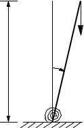
Solution:
1. Determine buckling load.
2. Draw free-body diagram and set up equilibrium equation


Substituting Eq. (b) in Eq. (a) gives
(c) (d)

Problem 2.19
An impulsive force applied to the roof slab of the building of Example 2.8 gives it an initial velocity of 20 in./sec to the right. How far to the right will the slab move? What is the maximum displacement of the slab on its return swing to the left?
Solution:
For motion of the building from left to right, the governing equation is
mu&& + ku = F (a)
for which the solution is
u(t ) = A2 cos ωnt + B2sinωnt uF (b)
With initial velocityof u&(0) and initial displacement
u(0) = 0 , the solution of Eq. (b) is &
u(t ) = sin
ωn
ω nt + u F (cos ω nt 1) (c) &
u(t ) = u&(0 )cos ωnt uFωn sin ωnt (d)
At the extreme right, u& (t ) = 0 ; hencefromEq (d) & 1 tan ω t = u n F (e)
n ω
Substituting ωn = 4 π , uF = 0 15 in and u& (0 ) = 20 in. sec in Eq. (e) gives
tan ωnt = 20 1 = 10 61
4π 0.15 or
sin ωnt = 0 9956; cosωnt = 0. 0938
Substituting in Eq (c) gives the displacementto the right:
u = 4 20 1)
π ( 0 9956) + 0 15 (0 0938 1. 449 in. =
After half a cycle of motion the amplitude decreases by
2uF = 2 × 0 15 = 0 3 in
Maximum displacementon the return swing is
u = 1 449 0 3 = 1 149 in
Problem 2.20
An SDF system consisting of a weight, spring, and friction device is shown in Fig. P2 20 This device slips at a force equal to 10% of the weight, and the natural vibration period of the system is 0 25 sec If this system is given an initial displacement of 2 in and released, what will be the displacement amplitude after six cycles? In how many cycles will the system come to rest?
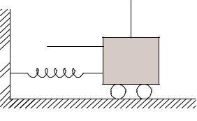
Figure P2 20
Solution:
Given:
F = 0.1w , Tn = 0. 25 sec
uF = F = 0.1w = 0.1mg = 0 1g = 0 1g k k 0 1g k ω2 (2π T )2 n n
= (8π)2 = 0 061 in
The reduction in displacementamplitude per cycle is
4uF = 0. 244 in.
The displacement amplitude after 6 cycles is
2.0 6 (0 244) = 2.0 1 464 = 0 536 in
Motion stops at the end of the half cycle for which the displacement amplitude is less than uF Displacement amplitude at the end of the 7th cycle is 0.536 – 0.244 = 0.292 in.; at the end of the 8th cycle it is 0.292 – 0.244 = 0 048 in.; which is less than uF Therefore, the motion stops after 8 cycles.
DynamicsProblem2.21of Structures 5th Edition Chopra SOLUTIONS MANUAL
Full download at : https://testbankreal.com/download/dynamics-of-structures-5th-edition-choprasolutions-manual/
Chopra
5th Edition
Dynamics of structures anil k chopra
Dynamics of Structures book by Anil K.
Chopra
Dynamics of Structures
Anil K. Chopra
Download ebook dynamics of structures
2 available editions
