BoldX is a wise choice for your glass-to-metal needs. BoldX is a world-class manufacturer of circular, glass-to-metal, hermetically sealed connectors. Our Qualified Products List (QPL) consists of MIL-DTL-26500 Bayonet and Threaded, MIL-DTL-83723 Series III, MIL-DTL-38999 Series I, II and III. We build commercial equivalents to MIL-DTL-26482 Series 1 and 2 as well as the MIL-DTL-5015 Series. We also supply your custom-design terminal seals, scoop-proof connectors, custom high-voltage applications, and harsh environment connectors. Whether your glass-to-metal requirement is standard or a special design, BoldX Industries is your wise choice.
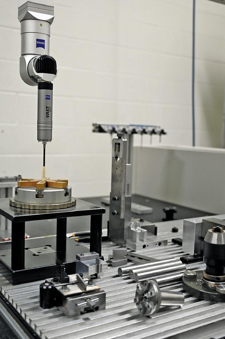
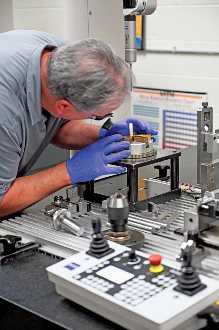
Our facility contains state-of-the-art equipment, quality systems, and engineering. Our dedicated people will meet or exceed your expectations in a timely manner. Whether your applications call for mild steel or corrosion-resistant seals, we offer contacts in a variety of alloys including Alumel, Chromel and 52 alloy, as well as plating finishes to meet your design requirements.
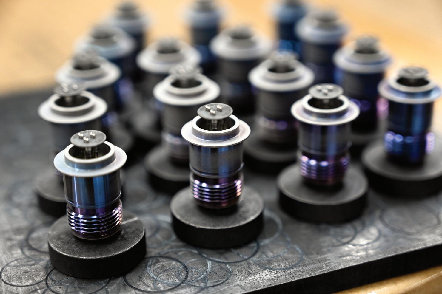
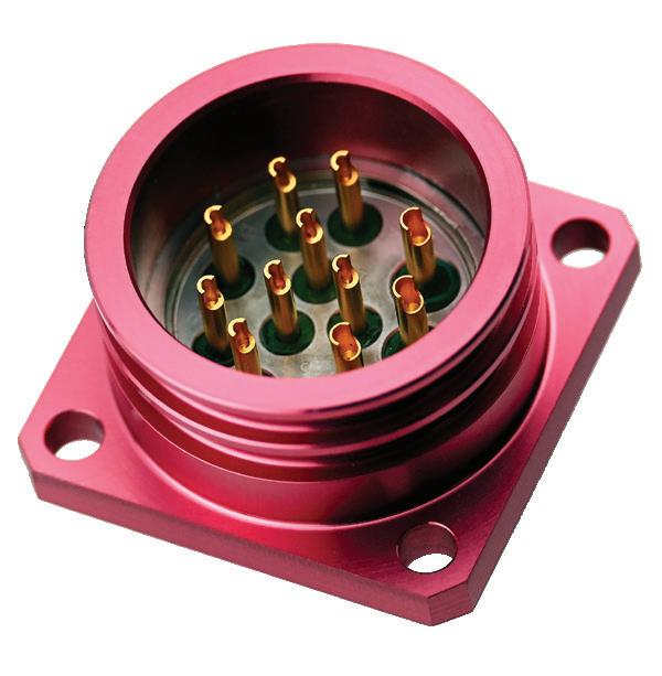
CIRCULAR HERMETIC CONNECTORS
CONTENTS
MILITARY SPECIFICATION
MIL-DTL-5015
MIL-DTL-38999 Series I (Scoop Proof)
MIL-DTL-38999 Series II (Low Silhouette)
MIL-DTL-38999 Series III (Triple Start Thread)
MIL-DTL-26500 Type B (Bayonet Coupling)
ML-DTL-26500 Type T (Threaded Coupling)
MIL-DTL-83723 Series III Type B (Bayonet Coupling)
Upgraded Version of MIL-DTL-26500 & Intermateable with MIL-DTL-26500 Type B)
MIL-DTL-83723 Series III Type T (Threaded Coupling)
(Upgraded Version of MIL-DTL-26500 & Intermateable with MIL-DTL-26500 Type T)
MIL-DTL-26482 Series 1
MIL-DTL-26482 Series 2
Cross Reference: MIL-Spec, Military Part Number, Description, AMPI Specification & Mating Plug
AMPI SPECIFICATION DESIGNATOR
A Receptacles
B Receptacles
C Receptacles
D Receptacles
G Receptacles
H Receptacles
J Receptacles
K Receptacles
R Receptacles
S Receptacles
MIL-DTL-5015
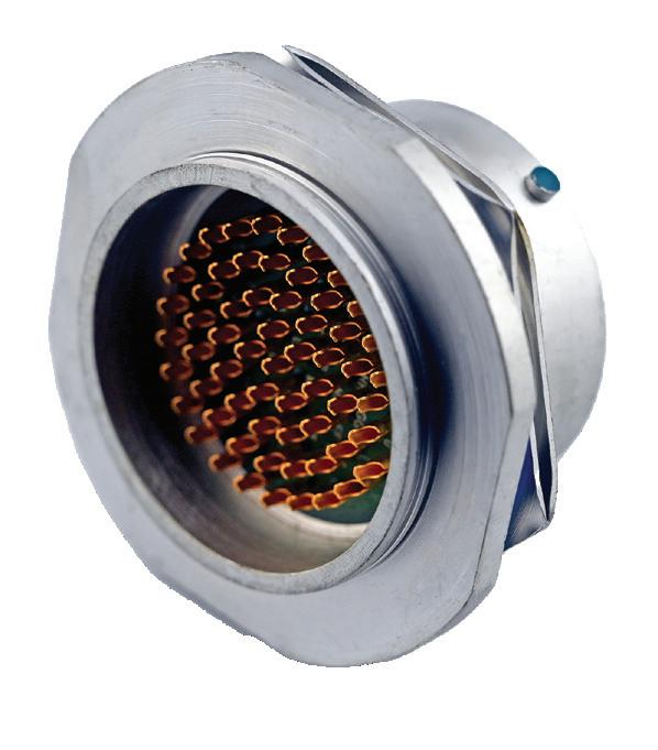
MIL-DTL-5015 hermetic connectors were developed for applications where a controlled atmosphere such as inert gasses, partial vacuums, or constant environments are needed. These receptacles are designed for use in electronic, electrical power, and control circuits.
The “A” Series receptacles are manufactured to BoldX Industries standards and meet the intermateability requirements of MIL-DTL-5015 as defined by MS33678. They are hermetically sealed with individual compression glass seals around each contact to prevent air leakage, in excess of .1 micron cubic foot per hour at one atmosphere.
Standard hermetic receptacles are supplied with either solder cup or eyelet type contact terminations. Contacts for other applications such as thermocouple or flex prints are also available. Standard receptacles are steel shells with tin plate and nickel-iron alloy contacts with a final coat of gold plate. Other materials and finishes can be supplied to meet specific application requirements.
“A” Series receptacles meet the instrumentation voltage requirements of MIL-DTL-5015. Connector receptacles with higher voltage ratings are available upon request. Connectors are designed to meet salt spray, shock, and vibration requirements of MIL-DTL-5015
ELECTRICAL SERVICE DATA
The maximum current to be carried by the connector, based on contact size, is the same as permitted by the wire bundle. Maximum current ratings and corresponding voltage drops under test condition, fully assembled, are shown below.
CONTACT SIZE
TEST CURRENT (AMPS) POTENTIAL DROP (MILLIVOLTS)
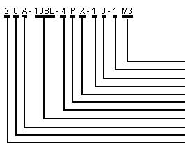
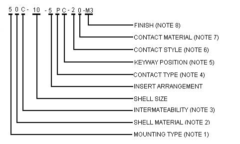
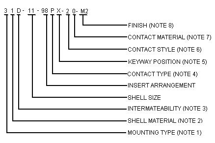
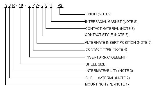
PART NUMBER EXPLANATION
STANDARD MATERIALS AND FINISHES
FERROUS ALLOY SHELLS
Material: Finish: Cold Rolled Steel per ASTM 108 100 m icroinches minimum fus ed tin per ASTM B545 over suitable underplate
STAINLESS STEEL SHELLS
Material: Corrosion-resistant steel per QQ-S-764, type 303 or as specified Finish:
CONTACTS
Material: Finish: Passivated
Nickel-iron alloy per MIL-I-23011, class 2
a. –Ferrous alloy shells; tin per ASTM B545 over copper per AMS 2418
b. –Stainless steel shells; 50 microinches minimum gold per ASTM B488 over suitable underplate
INSERTS INTERFACIAL GASKETS
Material: Glass Material: Fluorosilicone rubber
DESCRIPTION
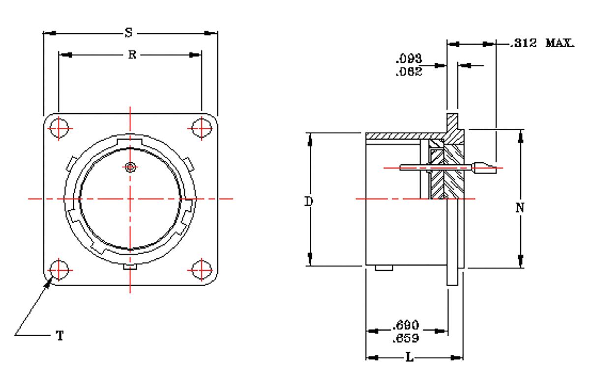
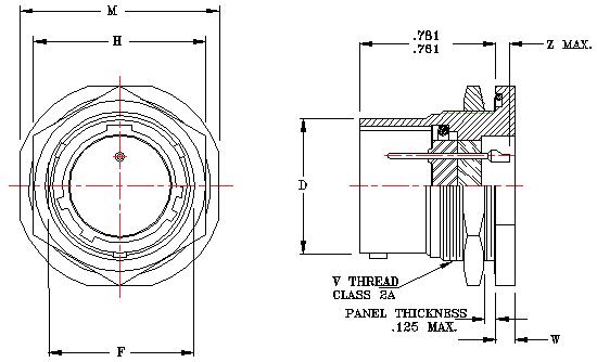
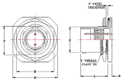
BOX MOUNT
SOLDER MOUNT CIRCULAR FLA NGE
MILITARY DESIGNATION
MS3142HS*C*P
MS3142HS*Y*P
MS3142HT*C*P
MS3142HT*Y*P
MS3143HS*C*P
MS3143HS*Y*P
MS3143HT*C*P
MS3143HT*Y*P
BOLDX DESIGNATION
MATING PLUG MS3106-MS3406-MS3456
HIGH-POTENTIAL TEST VOLTAGE
When specified, receptacles can be supplied to meet the requirements of MILDTL-5015. Standard receptacles are supplied to the Instrument Voltage rating. Consult factory for available tooling.
NOTES:
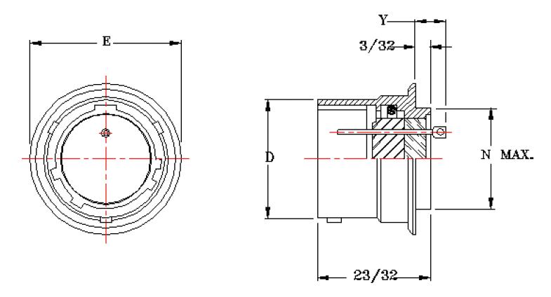
1-- Flangeless solder mount.
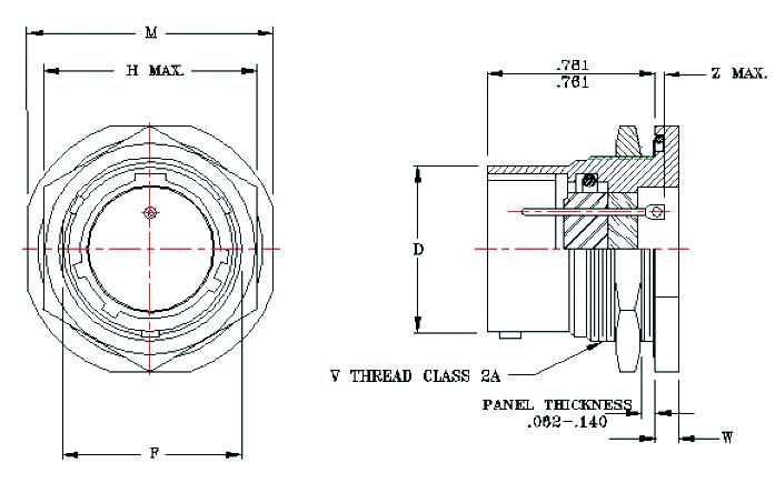
2-- Circular flange solder mount
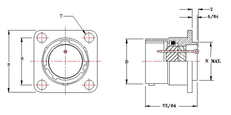
3-- Square flange box mount
0-- Ferrous alloy
1 thru 7- various stainless steel #303 thru #347
MIL-DTL-5015 intermateability
FIN ISH (NOTE 8)
IN TERFAC IA L GAS KE T (NO TE 7)
CONTACT MATER IAL (NO TE 6)
CONTACT STYLE (NOTE 5)
ALTERN ATE INSERT POS IT ION
CONTACT TYPE (NO TE 4)
INSERT ARR AN GEMENT
SHE LL S IZE
IN TERMATE AB ILITY (NO TE 3)
SHE LL M ATER IAL (NOTE 2)
MOUNTING TYPE (NOTE 1)
P-- Pin
1-- Eyelet
2-- Solder cup
3-- Short solder cup
0-- Nickel-iron alloy
Blank-- Without interfacial gasket
A1-- Fused tin over copper (25 hour salt spray)
M3-- Fused tin over copper over nickel with gold on contacts
M2-- Gold contacts with passivated shell
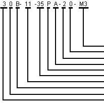
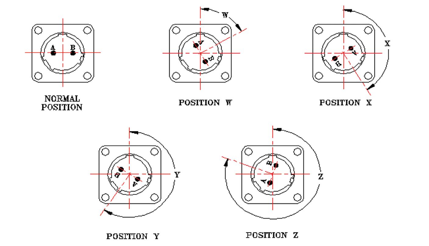
MIL-DTL-5015
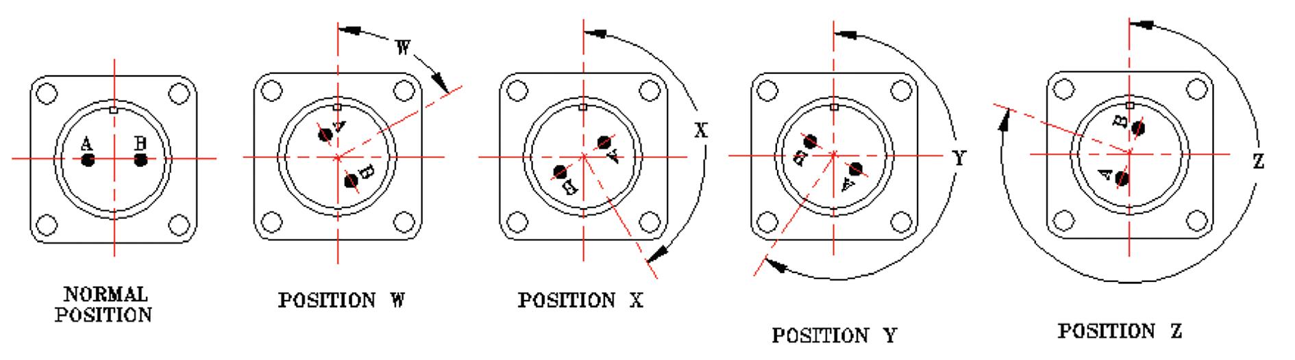
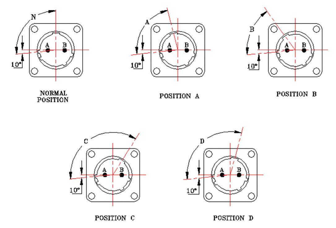
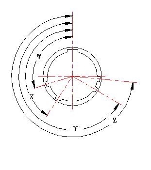
ALTERNATE INSERT POSITIONS
FRONT FACE OF PIN INSERT SHOWN
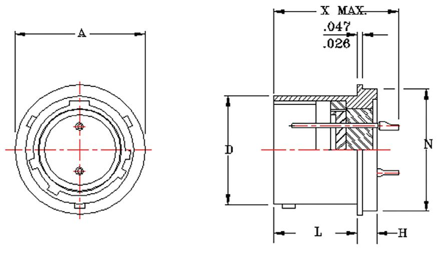
MIL-DTL-5015
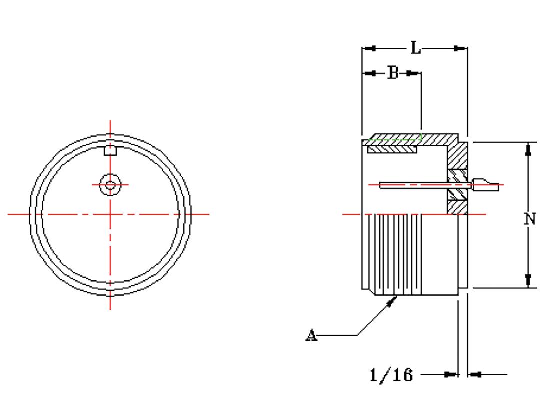
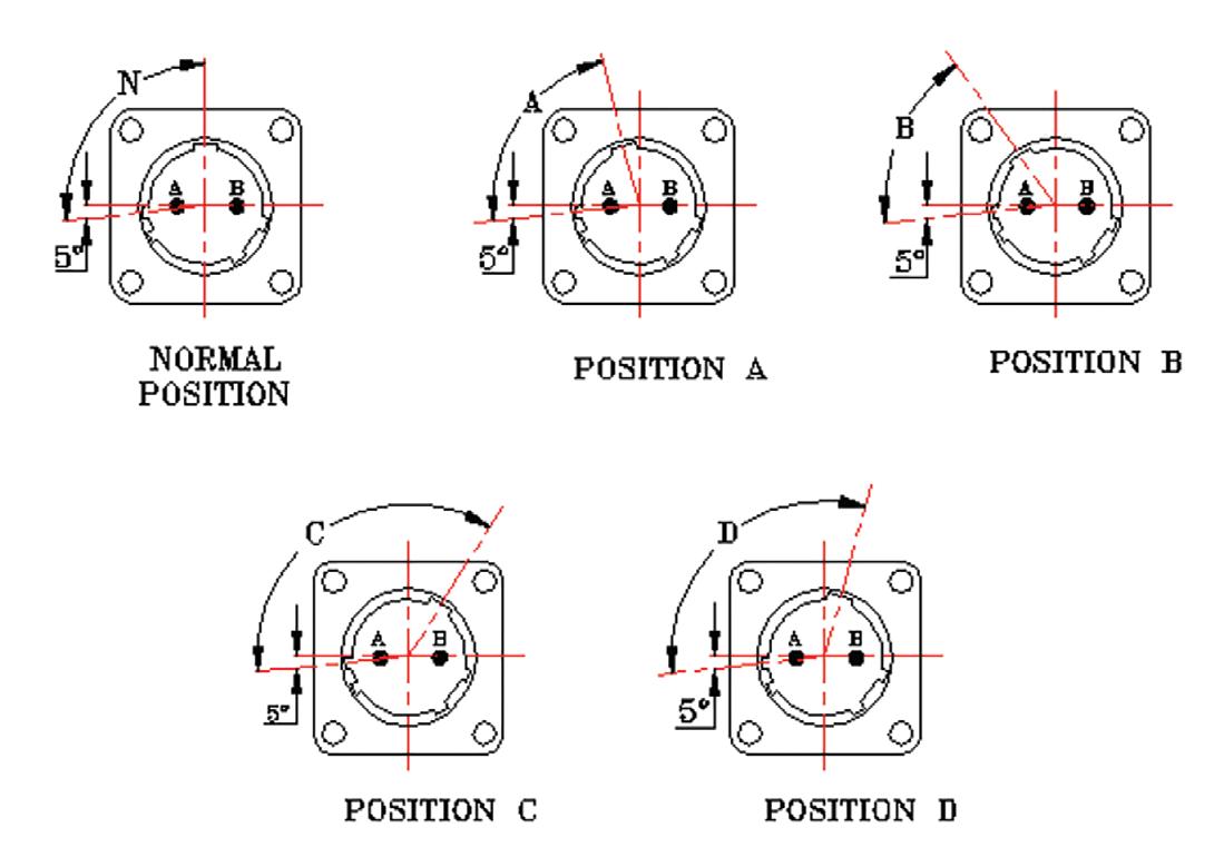
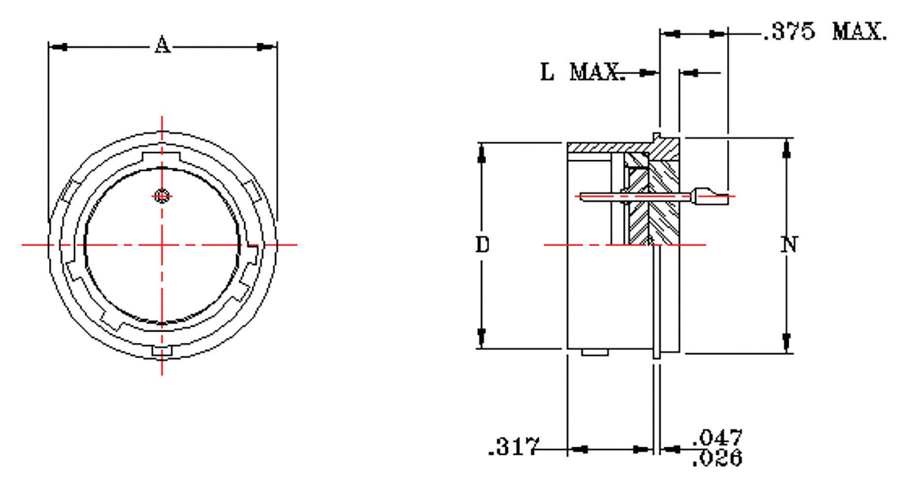
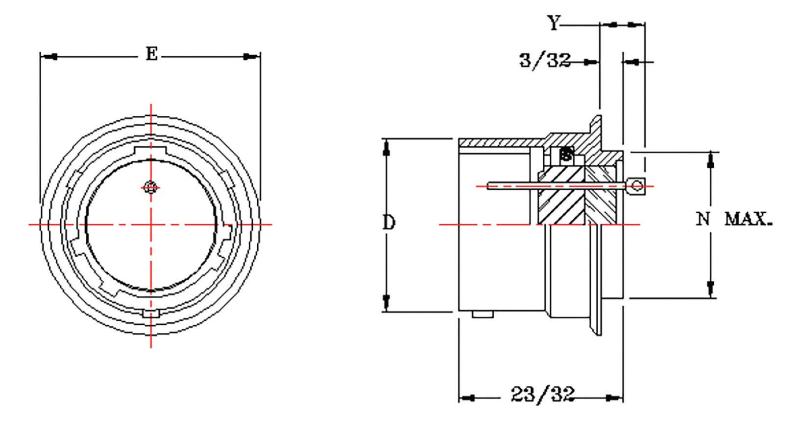
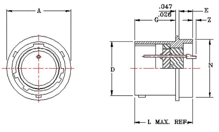
FLANGELESS SOLDER MOUNT
10A RECEPTACLES
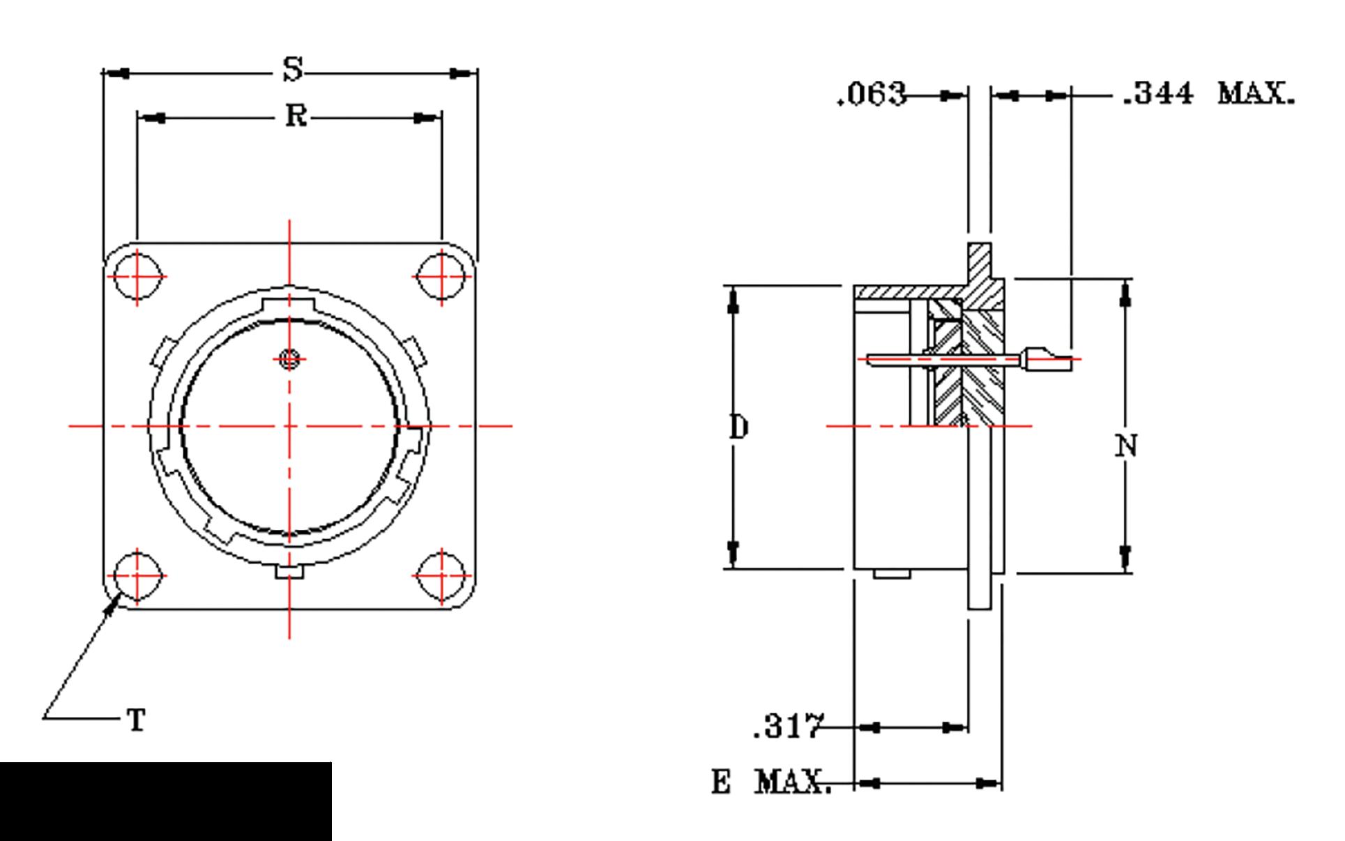
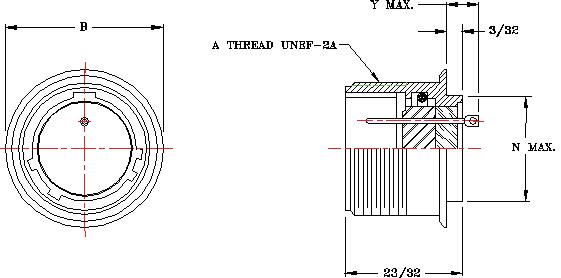
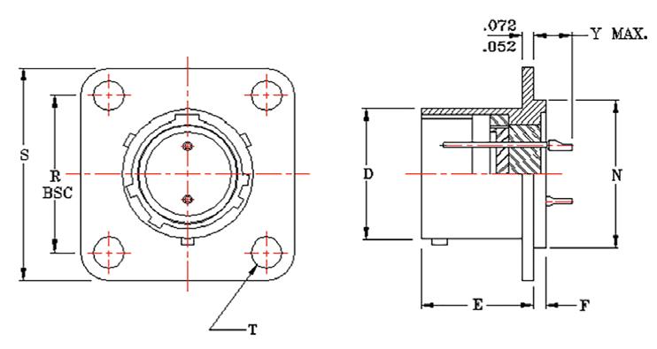
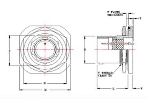
CIRCULAR FLANGE SOLDER MOUNT
20A RECEPTACLES (REF. MS3143)
MIL-DTL-5015
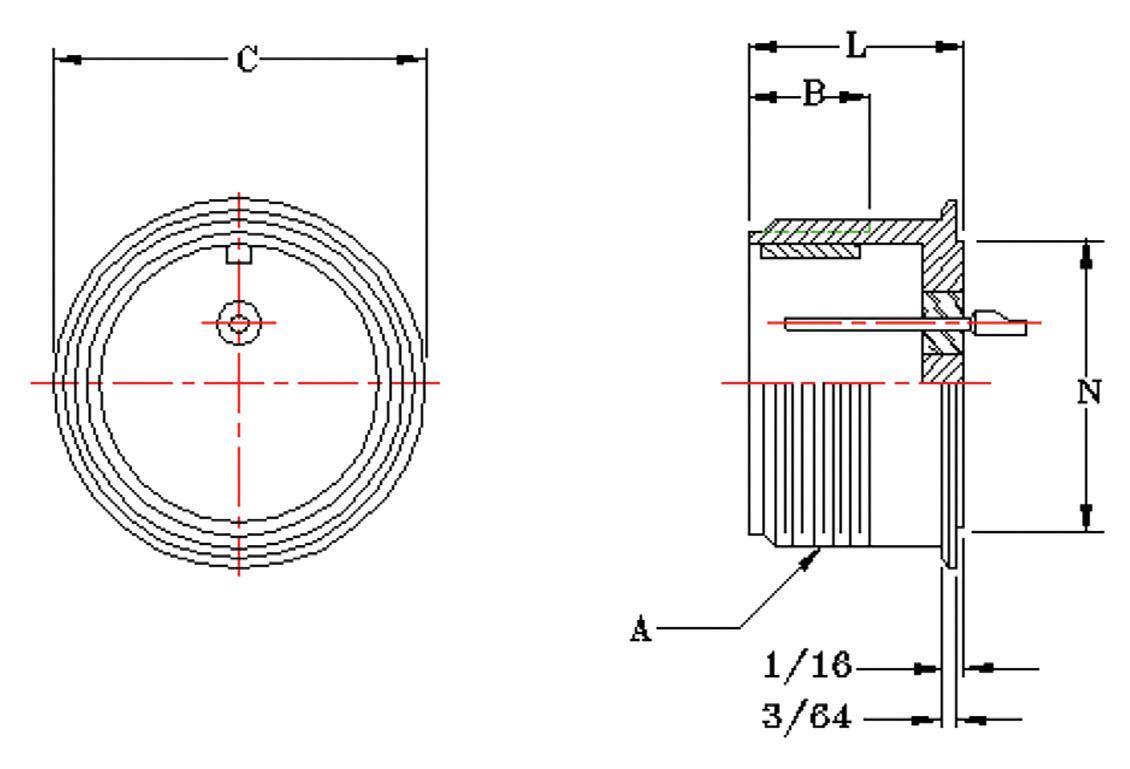
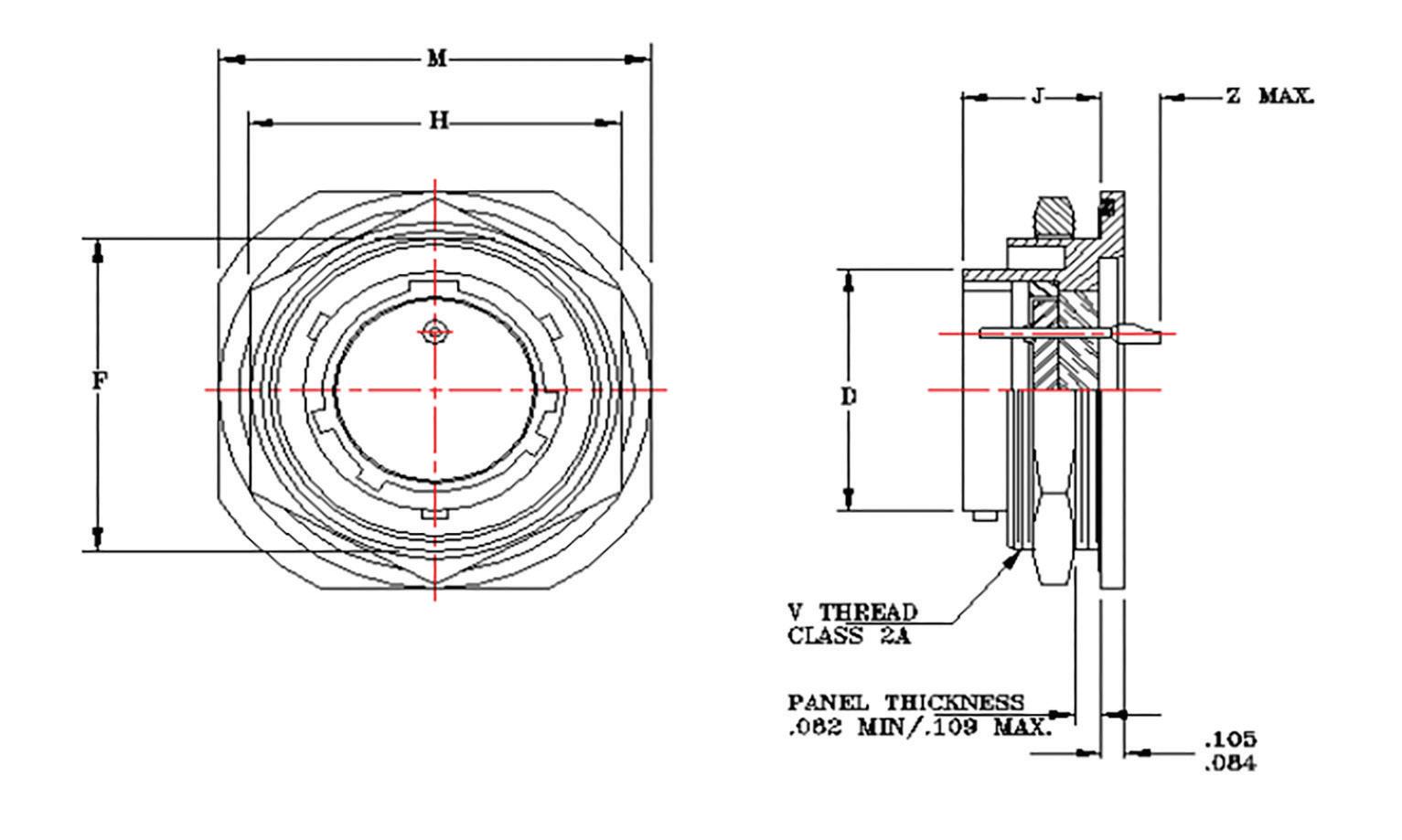
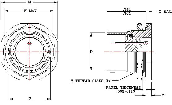
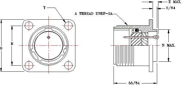
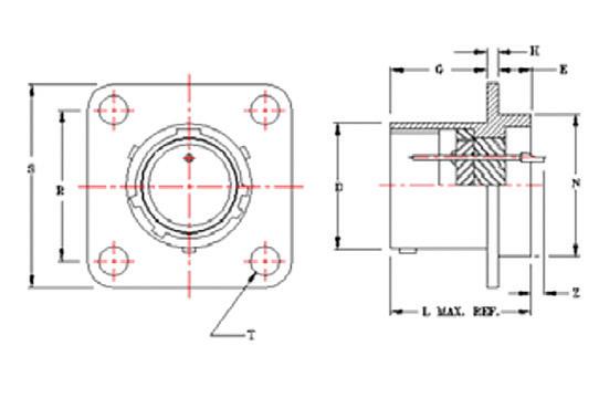
BOX MOUNT
30A RECEPTACLES (REF. MS3142
MIL-DTL-38999 (SERIES I)
B SERIES
MIL-DTL-38999 hermetic connectors were developed for applications where a controlled atmosphere such as inert gasses, partial vacuums, or constant environments are needed. These receptacles are designed for use in aerospace, electronic, electrical power, and control circuits.
The “B” Series receptacles are manufactured to BoldX Industries standards and meet the intermateability requirements of MIL-DTL-38999 Series I. They are hermetically sealed with an all-glass seal to prevent air leakage in excess of .01 micron cubic foot per hour at one atmosphere. They are manufactured with conductive finishes to provide electrical continuity between mated halves prior to contact engagement. Manufactured in the scoop-proof design, the contacts are located so as to prevent handling damage or inadvertent electrical contact.
Standard hermetic receptacles are supplied with either solder cup or eyelet type contact terminations. Contacts for other applications such as thermocouple or flex prints are also available. Standard receptacles are steel shells with nickel-iron alloy contacts and a final coat of tin plate and gold plated nickel-iron alloy contacts; or stainless steel shells passivated with gold plated contacts. Other materials and finishes can be supplied to meet specific application requirements.
“B” Series receptacles meet the voltage, salt spray, shock, and vibration requirements of MIL-DTL-38999.
ELECTRICAL SERVICE DATA
The maximum current to be carried by the connector, based on contact size, is the same as permitted by the wire bundle. Maximum current ratings and corresponding voltage drops under test condition, fully assembled, are shown below.
FINISH (NOTE 8)
CONTACT MATERIAL (NOTE 7)
CONTACT STYLE (NOTE 6)
KEYWAY POSITION (NOTE 5)
CONTACT TYPE (NOTE 4)
INSERT ARRANGEMENT
SHELL SIZE
INTERMATEABILITY (NOTE 3)
SHELL MATERIAL (NOTE 2)
(NOTE 1)
STANDARD MATERIALS AND FINISHES
FERROUS ALLOY SHELLS
Material: Finish: Cold Rolled Steel per ASTM 108 100 m icroinches minimum fus ed tin per ASTM B545 over suitable underplate
STAINLESS STEEL SHELLS
Material: Corrosion-resistant steel per QQ-S-764, type 303 or as specified
Finish:
CONTACTS
Material: Finish: Passivated
Nickel-iron alloy per MIL-I-23011, class 2
50 microinches minimum gold per ASTM B488 over a suitable underplate
BAYONET PINS
Material: Corrosion-resistant steel per QQ-S-764, type 303
INSERTS INTERFACIAL GASKETS
Material: Glass Material: Fluorosilicone rubber
DESCRIPTION
HIGH-POTENTIAL TEST VOLTAGE
2---Circular flange solder mount
3---Square flange box mount
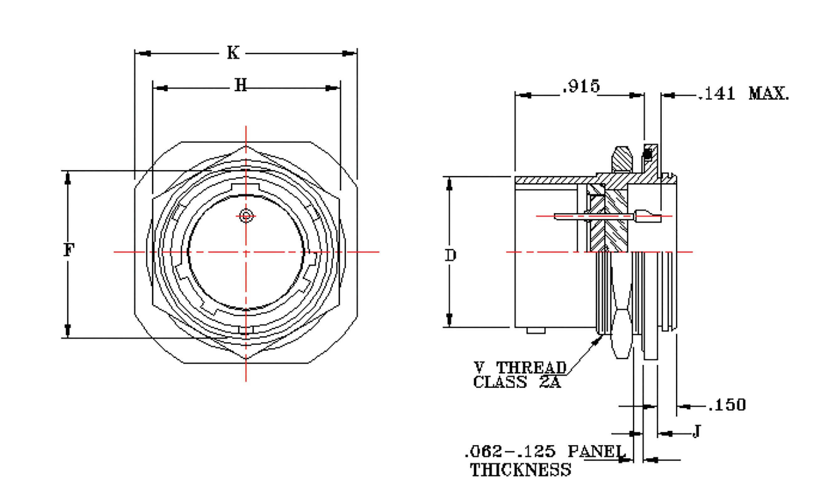
5---Jam nut mount
0---Ferrous alloy
1 thru 7- various stainless steel #303 thru #347
MIL-DTL-38999 series I intermateability
P---Pin
Alternate keyway position
1---Eyelet
2---Solder cup
0---Nickel-iron alloy
M3--Fused tin over copper over nickel with gold on contacts
M2--Gold contacts with passivated shell
M8--Gold contacts with nickel shell plated
MIL-DTL-38999 (SERIES I)
MASTER KEYWAY POSITIONS FRONT FACE OF PIN INSERT SHOWN
MIL-DTL-38999 (SERIES I)
SOLDER MOUNT 20B RECEPTACLES (REF. MS27471)
BOX MOUNT 30B RECEPTACLES
MIL-DTL-38999 (SERIES I)
JAM NUT MOUNT 50B RECEPTACLES (REF. MS27470)
MIL-DTL-38999 (SERIES II)
C SERIES
MIL-DTL-38999 hermetic connectors were developed for applications where a controlled atmosphere such as inert gasses, partial vacuums, or constant environments are needed. These receptacles are designed for use in aerospace, electronic, electrical power, and control circuits.
The “C” Series receptacles are manufactured to BoldX Industries standards and meet the intermateability requirements of MIL-DTL-38999 Series II. They are hermetically sealed with an all-glass seal to prevent air leakage in excess of .01 micron cubic foot per hour at one atmosphere. They are manufactured with conductive finishes to provide electrical continuity between mated halves prior to contact engagement. These connectors are manufactured in the low-silhouette design to minimize weight and size.
Standard hermetic receptacles are supplied with either solder cup or eyelet type contact terminations. Contacts for other applications such as thermocouple or flex prints are also available. Standard receptacles are steel shells with tin plating and gold plated, nickel-iron alloy contacts, or stainless steel shells passivated with gold plated, nickel-iron contacts. Other materials and finishes can be supplied to meet specific application requirements.
“C” Series receptacles meet the voltage, salt spray, shock, and vibration requirements of MIL-DTL-38999.
ELECTRICAL SERVICE DATA
The maximum current to be carried by the connector, based on contact size, is the same as permitted by the wire bundle. Maximum current ratings and corresponding voltage drops under test condition, fully assembled, are shown below.
STANDARD MATERIALS AND FINISHES
FERROUS ALLOY SHELLS
Material: Finish: Cold Rolled Steel per ASTM 108 100 m icroinches minimum fus ed tin per ASTM B545 over suitable underplate
STAINLESS STEEL SHELLS
Material: Corrosion-resistant steel per QQ-S-764, type 303 or as specified
Finish:
CONTACTS
Material: Finish: Passivated
Nickel-iron alloy per MIL-I-23011, class 2
INSERT PINS
Material: Fluorosilicone rubber 50 microinches minimum gold per ASTM B488 over a suitable underplate
INTERFACIAL SEALS
Material: Glass
BAYONET PINS
Material: Corrosion-resistant steel per QQ-S-764 type 303
DESCRIPTION
JAM NUT MOUNT
SOLDER MOUNT
MS27476Y*D*P
MS27476Y*D*X
MS27476Y*E*P
MS27476Y*E*X
MS27477Y*D*P
MS27477Y*D*X
MS27477Y*E*P
MS27477Y*E*X
MS27478Y*D*P
MS27478Y*D*X
MS27478Y*E*P
MS27478Y*E*X
30C-*-*P-20
50C-*-*P-20
50C-*-*P-10
51C-*-*P-20
51C-*-*P-10
20C-*-*P-20
20C-*-*P-10
21C-*-*P-20
21C-*-*P-10
MATING PLUG MS27473 - MS27484
HIGH-POTENTIAL
FINISH (NOTE 8)
CONTACT MATERIAL (NOTE 7)
CONTACT STYLE (NOTE 6)
KEYWAY POSITION (NOTE 5)
CONTACT TYPE (NOTE 4)
INSERT ARRANGEMENT
SHELL SIZE
INTERMATEABILITY (NOTE 3)
SHELL MATERIAL (NOTE 2)
MOUNTING TYPE (NOTE 1)
2-- Circular flange solder mount
3-- Square flange box mount
5-- Jam nut mount
0-- Ferrous alloy
1 thru 7- various stainless steel #303 thru #347
MIL-DTL-38999 series I intermateability
P-- Pin
Alternate keyway position
1-- Eyelet
2-- Solder cup
0-- Nickel-iron alloy
M3-- Fused tin over copper over nickel with Gold on contacts
M2-- Gold contacts with passivated shell
M8-- Gold contacts with nickel shel plated
MIL-DTL-38999 (SERIES II)
MIL-DTL-38999 (SERIES II)
SOLDER MOUNT 20C RECEPTACLES (REF. MS27478)
MOUNT
RECEPTACLES (REF. MS27476)
MIL-DTL-38999 (SERIES II)
JAM NUT MOUNT 50C RECEPTACLES (REF. MS27477)
MIL-DTL-38999 (SERIES III)
D SERIES
MIL-DTL-38999 hermetic connectors were developed for applications where a controlled atmosphere such as inert gasses, partial vacuums, or constant environments are needed. These receptacles are designed for use in aerospace, electronic, electrical power, and control circuits.
The “D” Series receptacles are manufactured to BoldX Industries standards and meet the intermateability requirements of MIL-DTL-38999 Series III. They are hermetically sealed with an all-glass seal to prevent air leakage in excess of 1. micron cubic foot per hour at one atmosphere.
They are manufactured with conductive finishes to provide electrical continuity between mated halves prior to contact engagement. Manufactured in scoop-proof design, the contacts are located so as to prevent handling damage or inadvertent electrical contact.
Standard hermetic receptacles are supplied with either solder cup or eyelet type contact terminations. Contacts for other applications such as thermocouple or flex prints are also available. Standard receptacles are stainless steel shells passivated with gold plated nickel-iron alloy contacts. Other materials and finishes can be supplied to meet specific application requirements.
“D” Series receptacles meet the voltage, salt spray, shock, and vibration requirements of MIL-DTL-38999.
ELECTRICAL SERVICE DATA
The maximum current to be carried by the connector, based on contact size, is the same as permitted by the wire bundle. Maximum current ratings and corresponding voltage drops under test condition, fully assembled, are shown below.
STANDARD MATERIALS AND FINISHES
STAINLESS STEEL SHELLS
Material: Corrosion-resistant steel per QQ-S-764, type 303 or as specified
Finish:
CONTACTS
Material: Finish: Passivated or nickel per AMS-QQ-N-290
INSERT
Nickel-iron alloy per MIL-I-23011, class 2
Material: Glass 50 microinches minimum gold per ASTM B488 over a suitable underplate
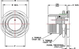
MIL-DTL-26500 hermetic connectors were developed for applications where a controlled atmosphere such as inert gasses, partial vacuums, or constant environments are needed. These receptacles are designed for use in aerospace, electronic, electrical power, and control circuits.
The “G” & “H” Series receptacles are manufactured to BoldX Industries standards and meet the intermateability requirements of MIL-DTL-26500 types B and T respectively. They are hermetically sealed with an all-glass seal to prevent air leakage in excess of 1x10⁻⁷ cc/sec of helium at one atmosphere.
The “G” series receptacles have a bayonet coupling mechanism and the “H” series have the threaded coupling type.
Standard hermetic receptacles are supplied with either solder cup or eyelet type contact terminations. Contacts for other applications such as thermocouple or flex prints are also available. Standard receptacles are steel shells, tin plated, with nickel-iron alloy contacts and a final coat of gold plate. Other materials and finishes can be supplied to meet specific application requirements. Both series are supplied with interfacial seals and O-rings.
STANDARD MATERIALS AND FINISHES
SHELLS
Material: Finish: Cold Rolled Steel per ASTM 108
Fused tin per ASTM B545 over copper per AMS over nickel per AMS-QQ-N-290
CONTACTS
Material: Finish:
Nickel-iron alloy per MIL-I-23011, class 2
Fused tin per ASTM B545 over copper per AMS over nickel per AMS-QQ-N-290
BAYONET PINS
Material: Corrosion-resistant steel per QQ-S-764 type 303
INSERTS
Material: Glass
INTERFACIAL SEALS and “O” RINGS
Material: Fluorosilicone rubber
NUT MOUNT MS24265H*B*CN 50G-*-*PN-20 MS24265H*B*EN 50G-*-*PN-10
MS27034H*B*CN 20G-*-*PN-20 MS27034H*B*EN 20G-*-*PN-10 BOX MOUNT CLASS H NOT SPECIFIED 30G-*-*PN-20
ELECTRICAL SERVICE DATA
The maximum current to be carried by the connector, based on contact size, is the same as permitted by the wire bundle. Maximum current ratings and corresponding voltage drops under test condition, fully assembled, are shown below.
MS27034H*T*CN 20H-*-*PN-20
MS27034H*T*EN 20H-*-*PN-10
50H-*-*PN-20 MS24265H*T*EN 50H-*-*PN-10 SOLDER MOUNT
BOX MOUNT CLASS H NOT SPECIFIED 30H-*-*PN-20 30H-*-*PN-10 MATING PLUG MS24266R*T*SN
HIGH-POTENTIAL TEST VOLTAGE
Unmated connectors tested per method 3001 of MIL-STD-1344 shall have a maximum leakage of 2 milliamperes and show no evidence of electrical breakdown or flashover.
NOTES: PART NUMBER EXPLANATION
FINISH (NOTE 8)
CONTACT MATERIAL (NOTE 7)
CONTACT STYLE (NOTE 6)
KEYWAY POSITION (NOTE 5)
CONTACT TYPE (NOTE 4)
INSERT ARRANGEMENT
SHELL SIZE
INTERMATEABILITY (NOTE 3)
SHELL MATERIAL (NOTE 2)
MOUNTING TYPE (NOTE 1)
2--Circular flange solder mount
3--Square flange box mount
5--Jam nut mount
0-- Ferrous alloy
1 thru 7- various stainless steel #303 thru #347
G-- MIL-DTL-26500 type B intermateability
H-- MIL-DTL-26500 type T intermateability
P--Pin
Alternate keyway position
1--Eyelet
2--Solder cup
0--Nickel-iron alloy
M3-- Fused tin over copper over nickel with gold on contacts
M2-- Gold contacts with passivated shell
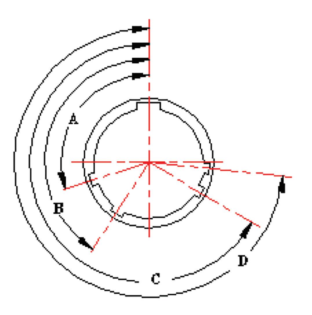
MIL-DTL-26500
INDEX OF INSERT ARRANGEMENTS
MIL-DTL-26500
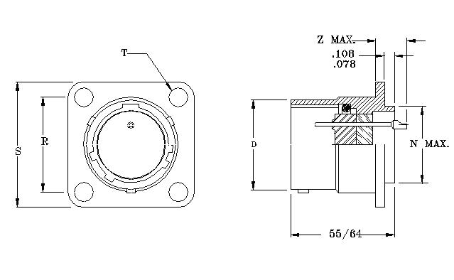
BOX MOUNT
30G RECEPTACLES (REF. MS24264)
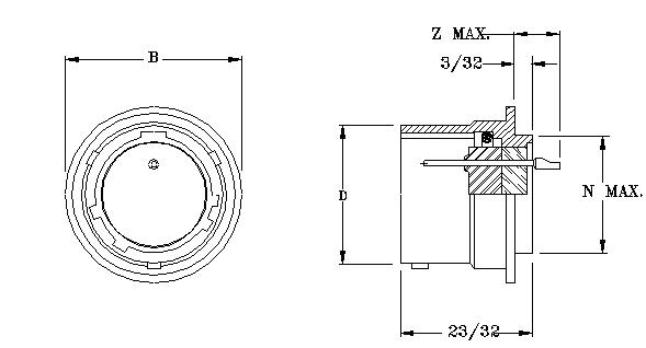
JAM NUT MOUNT
MIL-DTL-26500
SOLDER MOUNT 20H RECEPTACLES (REF. MS27034)
BOX MOUNT 30H RECEPTACLES (REF. MS24264)
JAM NUT MOUNT 50H RECEPTACLES (REF. MS24265)
MIL-DTL-83723 (SERIES III)
J & K SERIES
MIL-DTL-83723 hermetic connectors were developed for applications where a controlled atmosphere such as inert gasses, partial vacuums, or constant environments are needed. These receptacles are designed for use in aerospace, electronic, electrical power, and control circuits.
The “J” & “K” Series receptacles are manufactured to BoldX Industries standards and meet the intermateability requirements of MIL-DTL-83723 Series III types B and T respectively. They are hermetically sealed with a single compression glass seal around all contacts to prevent air leakage in excess of 1x10⁻⁷ cc/sec of helium at one atmosphere.
The “J” series receptacles have a bayonet coupling mechanism and the “K” series have the threaded coupling type. Standard hermetic receptacles are supplied with either solder cup or eyelet type contact terminations. Contacts for other applications such as thermocouple or flex prints are also available. Standard receptacles are tin plated steel shells or passivated stainless steel shells with gold plated nickel-iron alloy contacts. Other materials and finishes can be supplied to meet specific application requirements. Both series are supplied with interfacial seals and O-rings.
ELECTRICAL SERVICE DATA
The maximum current to be carried by the connector, based on contact size, is the same as permitted by the wire bundle. Maximum current ratings and corresponding voltage drops under test condition, fully assembled, are shown below.
STANDARD MATERIALS AND FINISHES
FERROUS ALLOY SHELLS
Material: Finish: Cold Rolled Steel per ASTM 108
100 microinches minimum fused tin per ASTM B545 over a suitable underplate
STAINLESS STEEL SHELLS
Material: Finish:
Corrosion-resistant steel per QQ-S-764, type 303 or as specified Passivated
CONTACTS
Material: Finish:
Nickel-iron alloy per MIL-I-23011, class 2
50 microinches minimum gold per ASTM B488 over a suitable underplate
BAYONET PINS
Material: Corrosion-resistant steel per QQ-S-764 type 303
INSERTS
Material: Glass
INTERFACIAL SEALS
Material: Fluorosilicone rubber
HIGH-POTENTIAL
Unmated connectors tested per method 3001 of MIL-STD-1344 shall have a maximum leakage of 2 milliamperes and show no evidence of electrical breakdown or flashover.
I 1500
FINISH (NOTE 8)
CONTACT MATERIAL (NOTE 7)
CONTACT STYLE (NOTE 6)
KEYWAY POSITION (NOTE 5)
CONTACT TYPE (NOTE 4)
INSERT ARRANGEMENT
SHELL SIZE
INTERMATEABILITY (NOTE 3)
SHELL MATERIAL (NOTE 2)
MOUNTING TYPE (NOTE 1)
JAM NUT MOUNT
M83723/80H**N
M83723/80Y**N
M83723/93H**N
M83723/93Y**N
M83723/81H**N
M83723/81Y**N
M83723/94H**N
M83723/94Y**N
20J-*-*PN-20
21J-*-*PN-20
20J-*-*PN-40
21J-*-*PN-40
50J-*-*PN-20
51J-*-*PN-20
50J-*-*PN-80
51J-*-*PN-80
MATING PLUG M83723/75 - M83723/77
THREAD COUPLING
M83723/88H**N
JAM NUT
M83723/89H**N
M83723/89Y**N
M83723/90H**N
M83723/90Y**N
MATING PLUG
N-20
N-20
M83723/86, M83723/91, M83723/95, M83723/97
2--Circular flange solder mount
3--Square flange box mount
5--Jam nut mount
0-- Ferrous alloy
1 thru 7- various stainless steel #303 thru #347
J--MIL-DTL-83723, series III type B intermateability
K-- MIL-DTL-83723, series III type T intermateability
P---Pin
Alternate keyway position
1--Eyelet
2--Solder cup
0--Nickel-iron alloy
M2-- Gold contacts with shell passivated
M3-- Fused tin contacts over nickel with gold on contacts
BAYONET COUPLING
MIL-DTL-83723 (SERIES III)
INDEX OF INSERT ARRANGEMENTS MIL-STD-1554
MIL-DTL-83723 (SERIES III)
MIL-DTL-83723 (SERIES III)
MIL-DTL-26482 (SERIES 1 & 2)
R & S SERIES
MIL-DTL-26482 hermetic connectors were developed for applications where a controlled atmosphere such as inert gasses, partial vacuums, or constant environments are needed. These receptacles are designed for use in aerospace, electronic, electrical power, and control circuits.
The “R” & “S” Series receptacles are manufactured to BoldX Industries standards and meet the intermateability requirements of MIL-DTL-26482 Series 1 and Series 2 respectively. They are hermetically sealed with a single compression glass seal around all contacts to prevent air leakage in excess of 1x10⁻⁶ cc/sec of helium at one atmosphere.
Standard hermetic receptacles are supplied with either solder cup or eyelet type contact terminations. Contacts for other applications such as thermocouple or flex prints are also available. Standard “R” series receptacles are tin plated steel shells with gold plated nickel-iron alloy. Standard “S” series receptacles are tin plated steel shells with gold plated nickel- iron alloy contacts. Other materials and finishes can be supplied to meet specific application requirements. Series 1 and 2 are supplied with interfacial gaskets and peripheral seals. Series 2 are supplied with raised seal barriers around each contact. Series 1 can be supplied with O-rings.
ELECTRICAL SERVICE DATA
The maximum current to be carried by the connector, based on contact size, is the same as permitted by the wire bundle. Maximum current ratings and corresponding voltage drops under test condition, fully assembled, are shown below.
HIGH-POTENTIAL
Unmated connectors tested per method 3001 of MIL-STD-1344 shall have a maximum leakage of 2 milliamperes and show no evidence of electrical breakdown or flashover.
STANDARD MATERIALS AND FINISHES
FERROUS ALLOY SHELLS
Material: Finish: Cold Rolled Steel per ASTM 108
R receptacles (series 1) fused tin over copper.
S receptacles (series 2)
100 microinches minimum fused tin per ASTM B545 over copper per AMS 2418 over nickel peR AMS-QQ-N-290
STAINLESS STEEL SHELLS
Material: Finish:
Corrosion-resistant steel per QQ-S-764, type 303 or as specified Passivated
CONTACTS
Material: Finish:
Nickel-iron alloy per MIL-I-23011, class 2
R receptacles (series 1)
50 microinches minimum gold per ASTM B488 over nickel per AMS-QQ-N-290
S receptacles (series 2)
50 microinches minimum gold per ASTM B488 over nickel per AMS-QQ-N-290
BAYONET PINS
Material: Corrosion-resistant steel per QQ-S-764 type 303
INSERTS
Material: Glass
JAM NUT MOUNT
INTERFACIAL SEALS
Material: Fluorosilicone rubber
MS3114H*A*P
MS3114H*B*P
MS3114H*C*P
MS3114H*Y*P
2-- Circular flange solder mount
3-- Square flange box mount
5-- Jam nut mount
0-- Ferrous alloy
1 thru 7- various stainless steel #303 thru #347
R-- MIL-DTL-26482, series I intermateability
S-- MIL-DTL-26482, series II intermateability
P---Pin
Insert position indicator
1--Eyelet
2--Solder cup
0--Nickel-iron alloy
Blank – Fluorosilicone gaskets
1- Silicone O-ring series I only
R series:
M3- Fused tin over copper over nickel with gold on contacts
M2- Gold contacts with shell passivated
S series:
M3- Fused tin over copper over nickel with gold on contacts
M2- Gold contacts with shell passivated
MIL-DTL-26482 (SERIES 1 & 2)
MIL-DTL-26482 (SERIES 1)
MIL-DTL-26482 (SERIES 2)
BOLDX MIL-SPEC
HERMETIC CONNECTOR PRODUCT GUIDE AND CROSS REFERENCE
MIL-DTL-38999
B SERIES QUALIFIED 6-9
C SERIES
BOLDX MIL-SPEC
HERMETIC CONNECTOR PRODUCT GUIDE AND CROSS REFERENCE
M83723/89H**N 50K-*-*PN -20
M83723/90H**N 20K-*-*PN -20
L51*20 -
From I-275 Take State Rt. 32 East 2.6 Miles. Turn Right onto Old St. Rt. 74 for 1.1 Miles. Turn Right on Armstrong Blvd. for 0.5 Miles. On the left is BoldX.