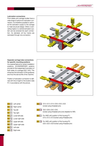
Lubrication connections Front plates and carriage bodies have a wide range of options for lubrication connection. It is therefore possible to optimise the lubrication supply to the carriage to meet structural design. Either a lubricating nipple or a central lubrication system can be screwed into each connection. As standard, all four tracks are lubricated through one connection.
Separate carriage lube connections for specific mounting positions As a special feature for certain installation positions, SCHNEEBERGER systems provide for the independant lubrication of both sides of a carriage (S32, S42). This enhances the lubrication of the guideway and thus the service life of the machine. Position of lubrication connection is defined with line of sight to the location side R1 in accordance with the picture.
Left center Right center Top left Top right Lower left side Lower right side Upper left side Upper right side Left side Right side
S10 + S12 + S13 + S20 + S22 + S23 locked using threaded pins S32 + S33 + S42 + S43 locked using threaded pins (only feasible for MR) For AMS with position of the housing P1: S10 + S12 + S13 locked using threaded pins For AMS with position of the housing P3: S20 + S22 + S23 locked using threaded pins
Lubrication as delivered condition The carriages fitted to guideways can be supplied with a wide variety of lubricants according to the demands of the application, storage life and the final type of lubrication. For applications that provide continuous lubrication during installation and operating phases, oiling with oil (LN) or a light application of grease (LG) are enough. A full application of grease (LV) is recommended for applications with manual lubrication.
Oil protect Grease protect Full greasing
Friction Push force is an important value within the system properties of a guideway. In the case of profile guideways, this is largely dependent on the friction of the sealing system. There is also friction from rolling contact and sliding friction when changing direction and returning. Application specific frictional forces, such as the type of lubrication, the amount of external load as well as speed, are also present. To minimize friction, SCHNEEBERGER profile guideways are manufactured with special plastics. To adjust friction from seals, sealing systems are available which have been adjusted to the application.
Coating For applications where special corrosion protection is necessary, such as in cleanroom applications or due to high levels of humidity or when increased wear resistance of the surface is required, MONORAIL carriages and rails are available in hard-chrome plated versions. The main advantages of applying this electroplated coating are: • Excellent corrosion protection • Very good wear resistance and surface load bearing capacity • Smooth and good emergency running characteristics due to its micropearl structure • Exceptional adhesion • Consistent depth of coating Please note that holes, threads and operating elements are not chrome-plated.
None Hard chromium
Grease nipples Grease nipple SN 6 Hydraulic-type grease nipple straight
Grease nipple SN 3-T Flush type grease nipple M3
Grease nipple SN 6-45 Hydraulic-type grease nipple45°
SW 7
M3
15,5
21
16
6,6
1,6
SW 5
10,5
15
SW 9
M6
M6
Grease nipple SN 6-T Flush type grease nipple M6
Grease nipple SN 6-90 Hydraulic-type grease nipple 90°
Grease gun SFP-T3 Grease gun for SN3-T and SN6-T
19
Ø 34
SW 9
Ø 5,5
12,5
M6
18
9,5
3
SW 7 55 210
M6
There are products having grease nipples, which can not be removed in the application. During rotation, this results in a collision between the grease nipple and: • the carriage • the guide rail • the connecting structure In this case, the carriage must be removed from the guide rail to replace the grease nipple.
Lubrication adapters Lubrication adapter SA 6-RD-M8x1 Lubrication adapter M8 round-head
Lubrication adapter SA 6-6KT-M8x1 Lubrication adapter M8 hexagon head
Lubrication adapter SA 6-6KT-G1/8 Lubrication adapter G1/8 hexagon head
Ø 10 G1/8
M8x1
1
M6
M6
M6
SW 12 20
14
SW 11 20
14
SW 8 20
14
M8x1
Pipe connection Swivel screw connection SV 6-M6-L Swivel screw connection M6 long (aluminum sealing)
Swivel screw connection SV 6-M8 Swivel screw connection M8 (aluminum sealing)
Swivel screw connection SV 6-M8-L Swivel screw connection M8 long (aluminum sealing)
Ø 10
Ø 10
Ø 10 M8x1
M8x1
M6x0,75
SW 9 22
M6
22
17
SW 9
M6
M6
SW 9 15,7
15,7 22
15,7
Screw-in connection SA 6-D4-RD Screw-in connection M6
Swivel screw connection SV 3-D3 Swivel screw connection for hose connection 3mm
27,2
27,2
Swivel screw connection SV 6-M6 Swivel screw connection M6 (aluminum sealing) Ø 10
17
M6x0,75
M6 SW 9 15,7 22
Hose connection
Ø3
23,5
12
9,5
Ø9
Swivel screw connection SV 6-D4-SW9 Swivel screw connection for hose connection 4mm
Swivel screw connection SV 6-D4-SW10 Swivel screw connection for hose connection 4mm
Ø9 Ø4
Ø 10 Ø4
18
23,1
SW 9 SW 10
M6 15,6
20,6
M3 9,2 11,3
M6
M3
M6 18
22,6
Ø6
SW 6 Ø5
Ø4
Ø6
16,5
Ø3
12,5
Screw-in connection SA 3-D3 Screw-in connection M3
General area of application under normal conditions of use Movement
MR
Maximum speed
3 m/s
Maximum acceleration
50 m/s
BM 5 m/s 2
100 m/s2
Higher values are permissible, but are dependent on the type of carriage, lubrication, position when installed, pretension and load. If this is the case, please contact a SCHNEEBERGER agency before proceeding.
Working environment
MR
BM
Working temperature
-40 °C - +80 °C
-40 °C - +80 °C
Transportation temperature
-40 °C - +80 °C
-40 °C - +80 °C
Storable under the following storage conditions
3 years
3 years
Storage conditions
0° - 40° storage temperature < 75% humidity No chemical gases, vapors or liquids
0° - 40° storage temperature < 75% humidity No chemical gases, vapors or liquids
Materials Rail
Roller bearing steel, hardened surfaces
Carriage
Roller bearing steel, fully hardened
Rolling element
Roller bearing steel, fully hardened
Synthetic parts
POM, PAPA, TPU injection moulded
Safety instructions! Caution: Carriages can come loose from the guide rail if they are overloaded, inadequately lubricated or improperly serviced. Appropriate design and technical safety measures need to be taken by the user, which prevent separation of carriage and guide rail in case of an error (e.g. due to loss of rolling element). A possible variant in a design measure is a safety clamp around the guide rail. The specifications of professional associations, relevant guidelines and standards for the application in question must also be observed.