SANTIAGO CALA ARCHITECTURE PORTFOLIO
1
1 Contents Curriculum Vitae 2 Summary of Works 4 Selected Works 4 Other Works 6 Selected Works 9 Abrahamic Family House 10 George Street Plaza Building 20 Kiran Nadar Cultural Cenrtre 32 Aishti Foundation 42 Parque España Library 54 Fifty Five Blair Road 60 Other Works 67 King Salmam Pavilion 68 Latvian Museum of Contemporary Art 74 Five Strand 80 Valextra 84 Liverpool Biennial 88 Ephemeropterae Pavilion Vienna 92 Feme London Headquarters 96 COS Stores Europe 100

Santiago Calà
Mobile +44 7706170716
Email: santicala@mail.com www.santiagocala.com
Professional Experience
Architect with over 10 years of experience working on a wide range of international projects, from luxury residential developments to contemporary art museums. Extensive experience in the development of concept and planing documentation as well as construction packages for multi-million pound, high profile projects. Expertise managing teams and coordinating consultants, meticulous designer with great attention to details while diligent and efficient delivering exceptionally built projects.
Adjaye Associates, London, UK
Project Architect
Primarily responsible for designing architectural projects, consultant liaison and coordination of several technical packages on a wide range of projects from commercial developments to cultural centres. Successful completion of different architectural projects throughout all the key RIBA stages.
2011 - Present
Minale & Mann, London, UK
Architect Designer
Concept design construction detailing of interior design projects with commercial and residential programs. Preparation of tender documentation construction monitoring.
2010 - 2011
COS Stores Interior Department, London, UK
Interior Design Architect
Fit out documentation and construction detailing for several COS stores in Europe. Also prototyping and product design of shop furniture and accessories.
2009 - 2010
Giancarlo Mazzanti Arquitectos, Bogotá, Colombia
Architect Designer
Concept design and construction detailing of Parque España Library and other projects.
2007 - 2008
ONG&ONG Architects, Singapore
Architectural Assistant
Concept design and construction detailing of several residential projects across southeast Asia.
2006 - 2007
Profile
Education
Architectural Association, London, UK
Graduate School of Architecture
Master in Science (MSc) Sustainable Environmental Design (Graduated with Commendation)
2010 - 2011
Pontificia Univesidad Javeriana, Bogotá, Colombia
Architecture and Urban Planing Faculty
Bachelor of architecture (BA Arch) Qualified Architect (Part 3 Equivalent)
Registered Architect SCA N0387583
2002 -2007
Awards
Software
International Competition for Bicycle Centre & Argelia II School, Bogota, Colombia Solo entry
3rd Place, Honorable mention and participation in the final exhibition 2017
International Competition for the refurbishment of Hospital Facade, San José, Costa Rica Solo entry
2nd Place and cash prize. 2016
Revit
Autocad
Vectorworks
Sketchup
Rhino
Languages
Spanish: Native
English: Proficient
Italian: Basic
Indesign
Illustrator
• • • • •
• • • • •
• • • • •
• • • • •
• • • • •
• • • • •
• • • • • Adobe
• • • • • Microsoft Office • • • • • Vray • • • • • Enscape • • • • • 3dMax • • • • •
Adobe Photoshop
Adobe
SELECTED WORKS
ABRAHAMIC FAMILY HOUSE
(Competition, Winning Scheme)
60.000m2 Civic/Cultural Centre
Abu Dhabi, UAE
RIBA Stages 1 - 6 ( Built ) 2020
• Design and Preparation of competition proposal and submission material.
• Consultant liaison and coordination of structural, mechanical packages.
• Tender and Stage 4 construction documents preparation.
• Periodic construction monitoring and supervision of satisfactory workmanship.
GEORGE STREET PLAZA BUILDING
(Competition, Winning Scheme)
1.200m2 Comunity Centre
Sydney, Australia
RIBA Stages 1- 6 ( Built ) 2019
• Design and Preparation of competition proposal and submission material.
• Consultant liaison and coordination of structural and mechanical packages.
• Tender and Stage 4 construction documents preparation.
• Periodic construction monitoring and supervision of satisfactory workmanship.
KIRAN NADAR CULTURAL CENTRE
100.000m2 Museum of Art/Cultural Centre
New Delhi, India
RIBA Stages 1- 6 (Under Construction) 2022
• Design and Preparation of competition proposal and submission material.
• Consultant liaison and coordination of several technical packages.
• Tender and Stage 4 construction documents preparation.
4
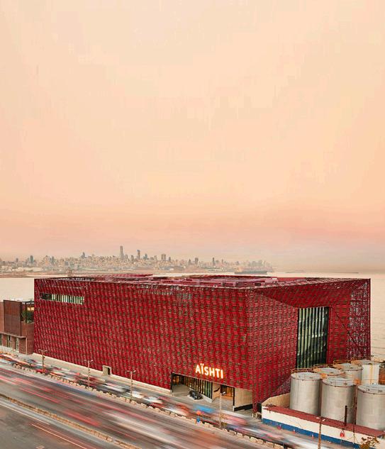
AISHTI FOUNDATION BEIRUT
35.000m2 Cultural Complex Beirut, Lebanon
RIBA Stages 1 - 6 (Built) 2013
• Design and preparation of proposal and submission material
• Consultant liaison and coordination of landscape, structural, facade and mechanical package
• Tender and construction documents preparation
• Periodic construction monitoring and supervision of satisfactory workmanship.
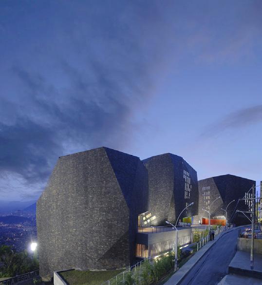
PARQUE ESPAÑA LIBRARY
5..500m2 Cultural Complex, Medellin, Colombia
RIBA Stages 1- 6 Equivalent (Built) 2008
• Design and Preparation of proposal and submission material
• Consultant liaison and coordination of structural and mechanical packages
• Tender and construction documents preparation
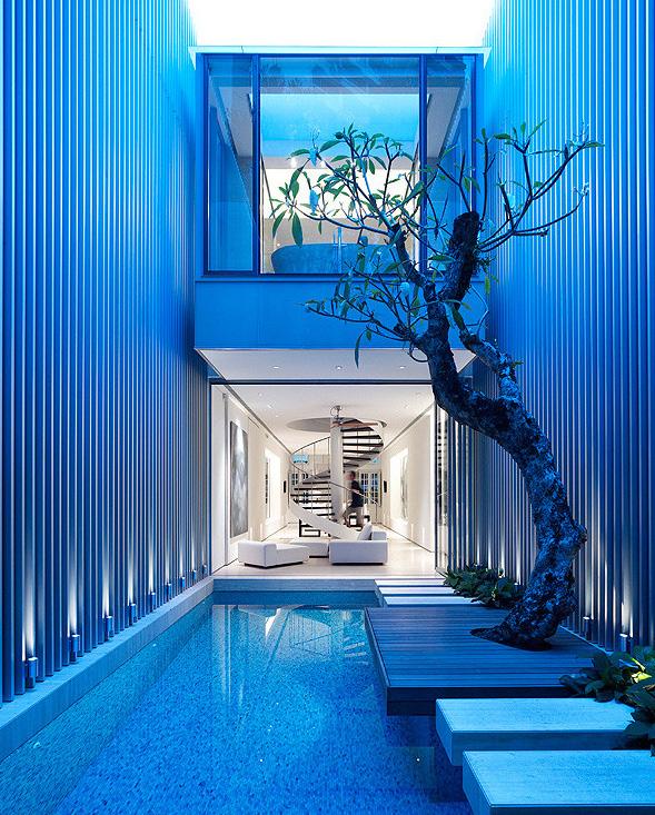
FIFTY FIVE BLAIR ROAD
280m2 Private House Singapore
RIBA Stages 1 - 6 Equivalent (Built) 2007
• Design and Preparation of proposal and submission material
• Consultant liaison and coordination of, structural, lighting and mechanical packages
• Tender and construction documents preparation
• Construction monitoring and supervision of satisfactory workmanship.
5
OTHER WORKS
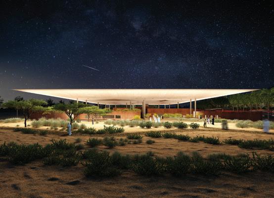

KING SALMAN PARK VISITOR PAVILION
(Competition, Winning Scheme)
7.000m2 Visitor Centre
Riyadh, Saudi Arabia
RIBA Stages 1- 4 ( Under Construction ) 2018
• Design and Preparation of competition proposal and submission material.
• Consultant liaison and coordination of structural and mechanical packages.
• Tender and construction documents preparation.
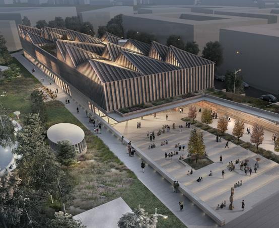
LATVIAN MUSEUM OF CONTEMPORARY ART
(Competition, Winning Scheme)
7.000m2 Art Museum, Riga, Latvia
RIBA Stages 1- 4 ( Suspended ) 2017
• Design and Preparation of competition proposal and submission material.
• Consultant liaison and coordination of structural and mechanical packages.
• Tender and construction documents preparation.
FIVE STRAND
(Competition, Winning Scheme)
14.000m2 Resi/Office Complex
London, UK
RIBA Stages 1-3 (Planning Approved - Unbuilt) 2016
• Design and Preparation of competition proposal and submission material.
• Consultant liaison and coordination of structural and mechanical packages.
• Preparation of Planning Application Report for Westminster Council and English Heritage.
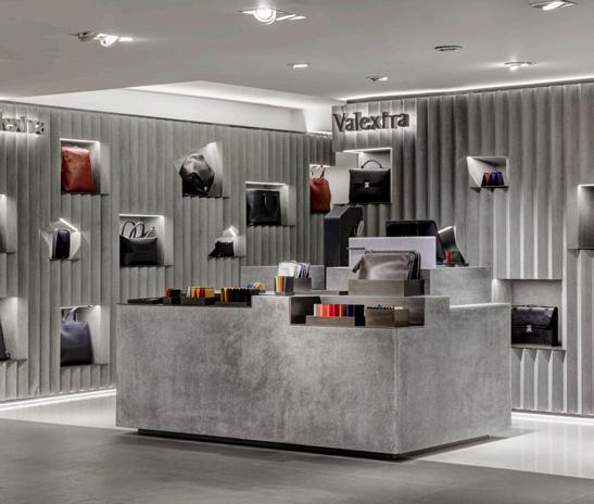
VALEXTRA
20m2 Instore Concession
London, UK
RIBA Stages 1-6 (Built) 2015
• Design and Preparation of proposal and submission material
• Tender and construction documents preparation
• Construction monitoring and supervision of satisfactory workmanship.
6
2016 support of proposals for a new mixed-use London WC2 (‘the Site’). It explains the rationale, design evolvement that has taken place, leading planning application. trading as Alchemi Group, the development the applicant1 held an architectural competition concept and commercial viability for 5 Strand. Adjaye Associates, who were subsequently design and building feasibility resulting in the a development of the highest quality that context, strengthening the relationship between the Square Conservation Area. The proposal will reretail accommodation on ground floor and much accommodation above, whilst enhancing the surrounding subject to extensive consideration as a result of positively in design and land use terms. SUMMARY Fig.1.1 View of the Proposal from The Strand Securities Services Trust Company (Jersey) Limited & BNP Paribas Limited as trustees of the BlackRock UK Property Fund.
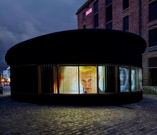
LIVERPOOL BIENNIAL
160m2 Temporary pavillion Liverpool, UK
RIBA Stages 1-6 (Built) 2014
• Design and Preparation of design proposal and submission material
• Tender and construction documents preparation
• Construction monitoring and supervision of satisfactory workmanship.
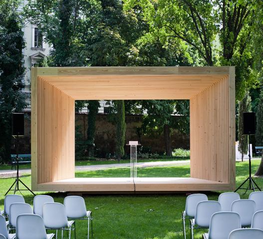
EPHEMEROPTERAE PAVILION VIENNA
2.5X6.7m Temporary Pavilion
Vienna, Austria
RIBA Stages 1 - 6 (Built) 2012
• Design and Preparation of design proposal and submission material
• Tender and construction documents preparation
• Construction monitoring and supervision of satisfactory workmanship.
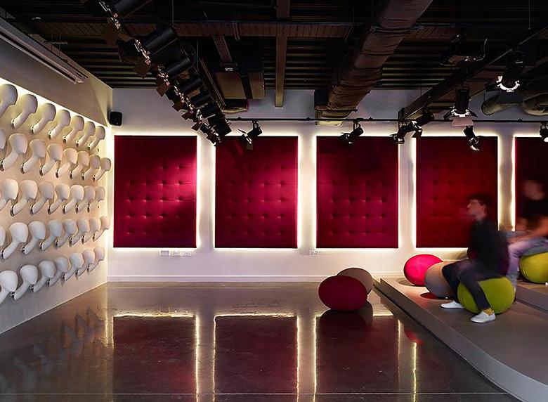
FEME LONDON HEADQUARTERS
950m2 Corporate Headquarters London, UK
RIBA Stages 1 - 6 (Built) 2010
• Design and Preparation of design proposal and submission material
• Tender and construction documents preparation
• Construction monitoring and supervision of satisfactory workmanship.
COS STORES EUROPE
COS Stores Frankfurt, Barcelona, Milan, London London, UK
RIBA Stages 1 - 6 (Built) 2009
• Design and preparation of store fit-outs
• Product design of furnishing pieces for stores
• Tender and construction documents preparation
• Construction monitoring and supervision of satisfactory workmanship.
7
8
SELECTED WORKS
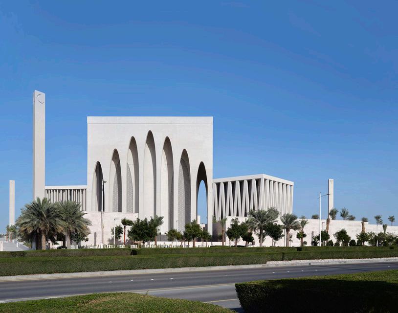
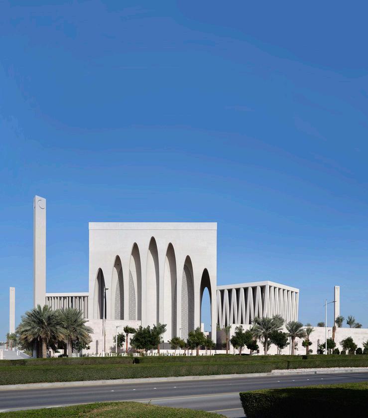
ABRAHAMIC FAMILY HOUSE
(Competition, Winning Scheme)
60.000m2 Civic/Cultural Centre
Abu Dhabi, UAE
RIBA Stages 1 - 6 ( Built )
2020
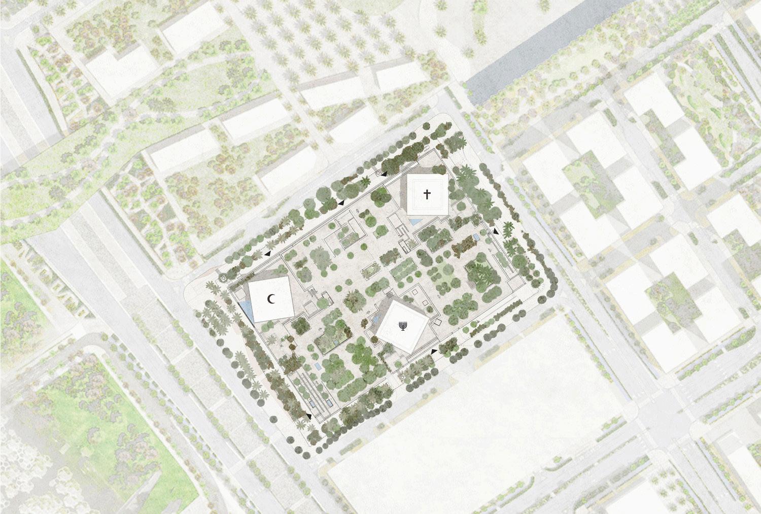
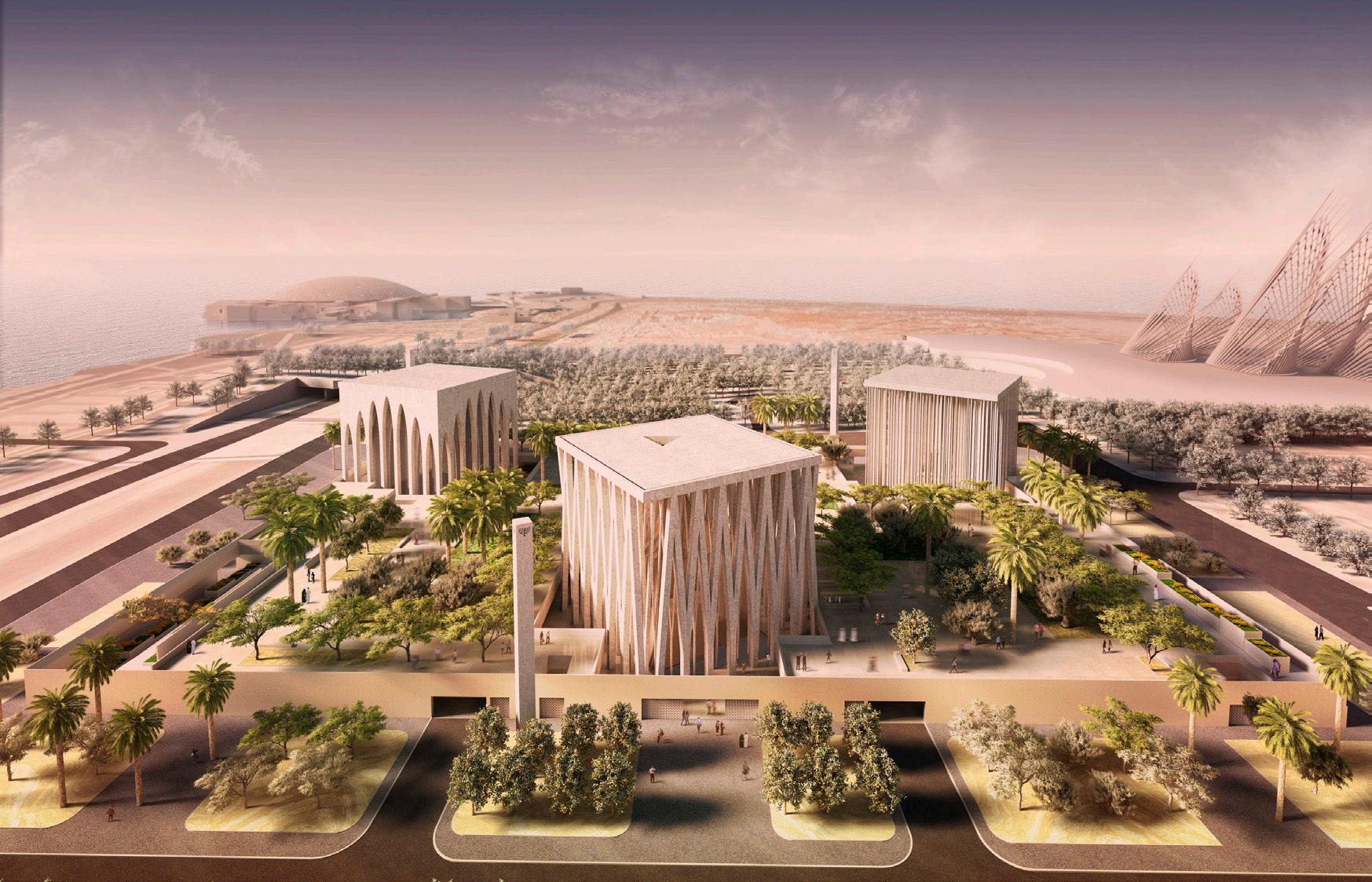
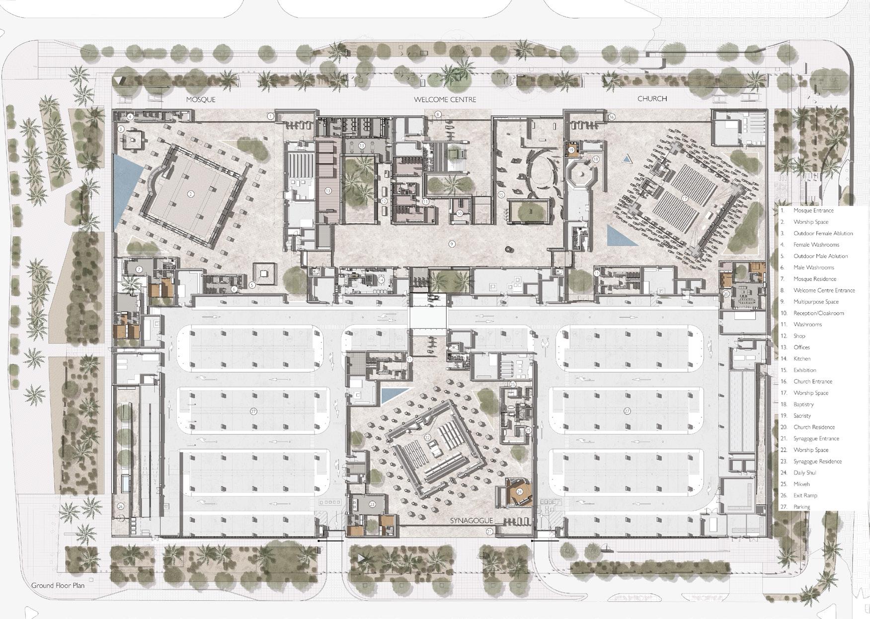
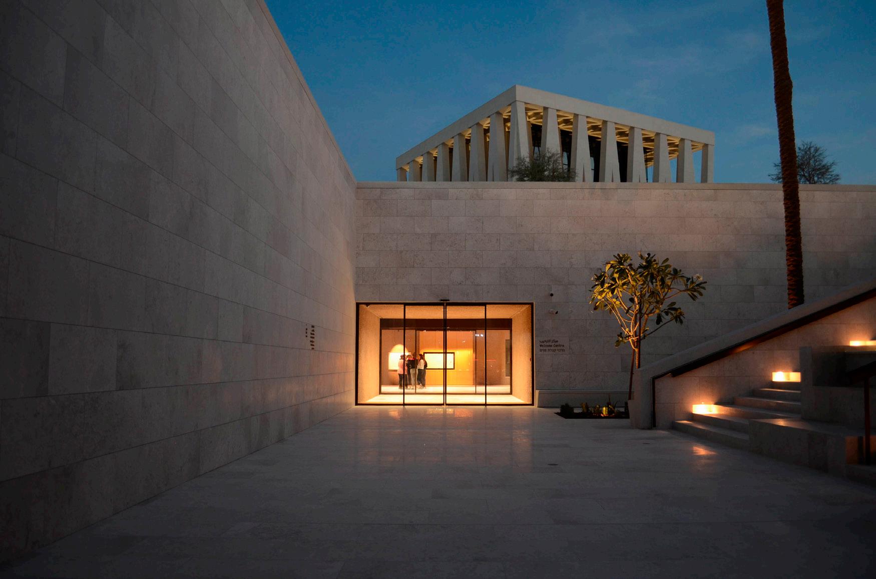
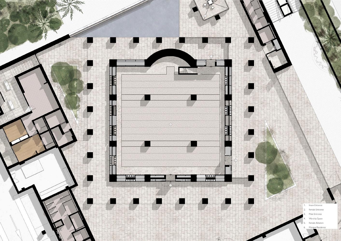
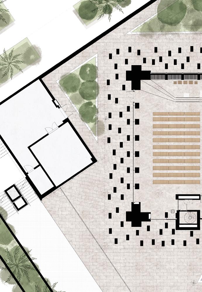
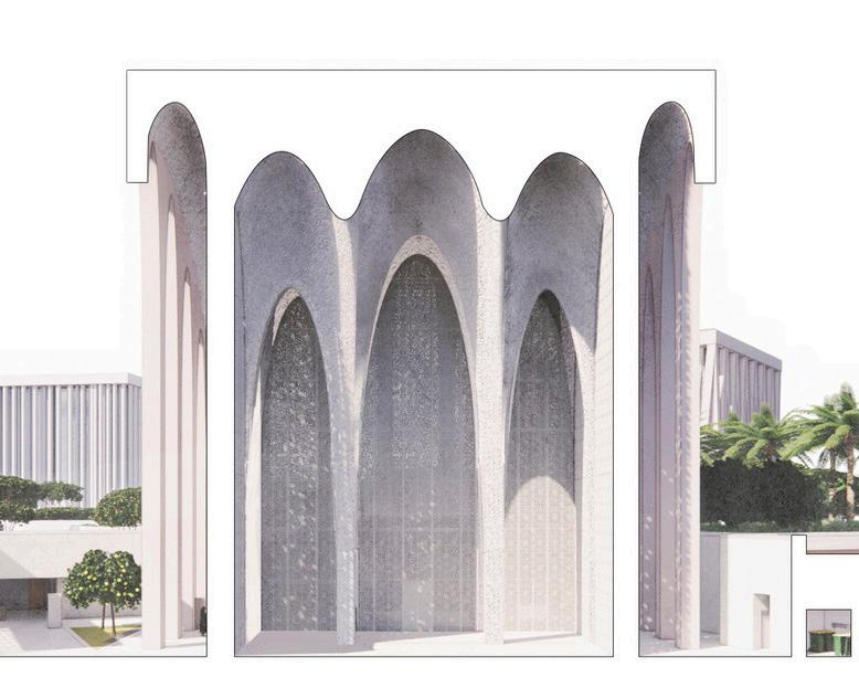
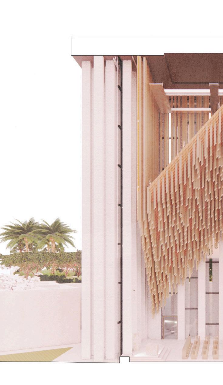
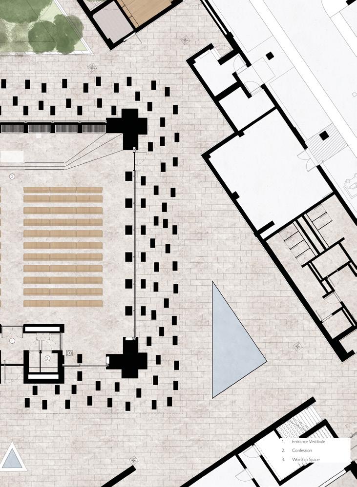
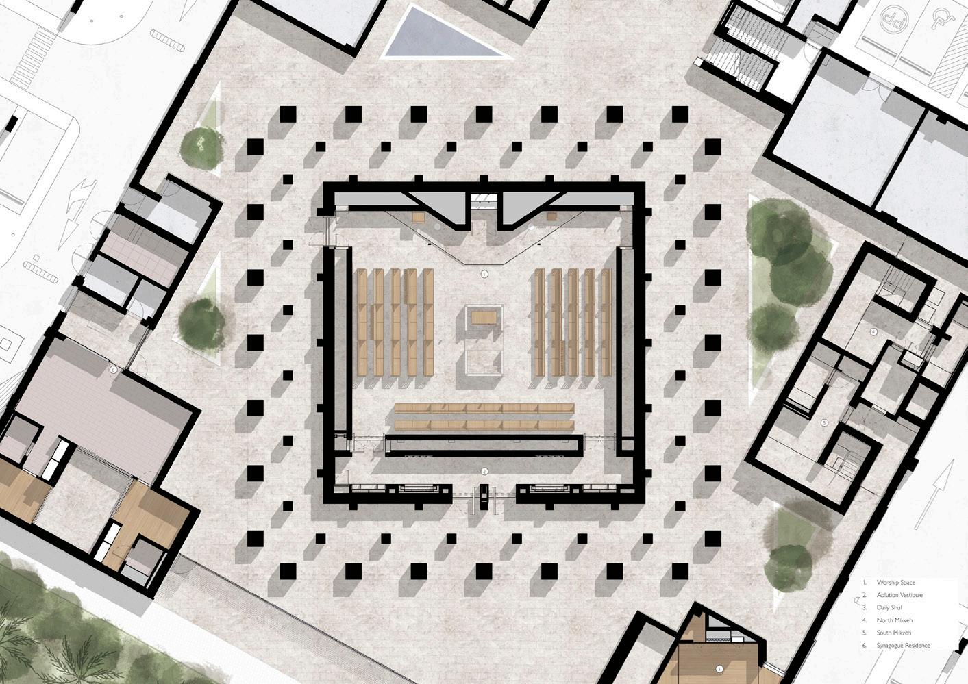
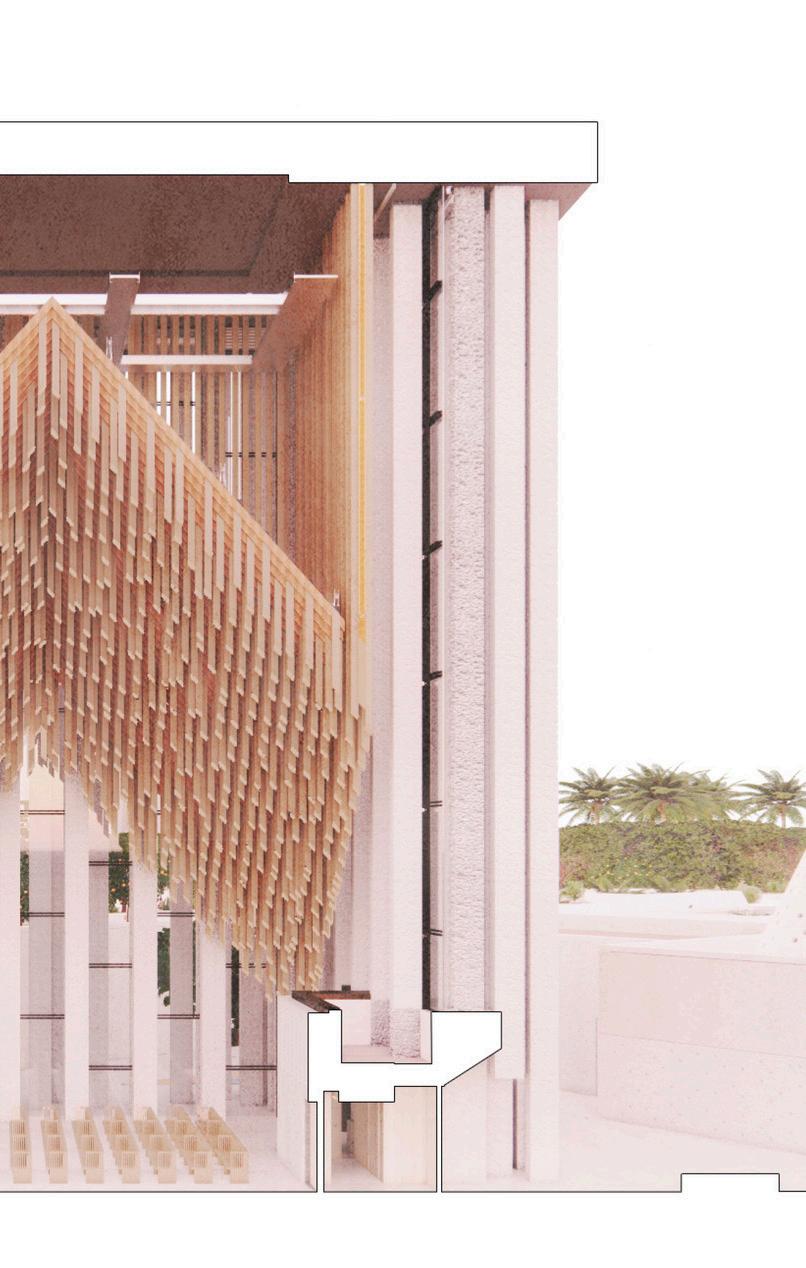
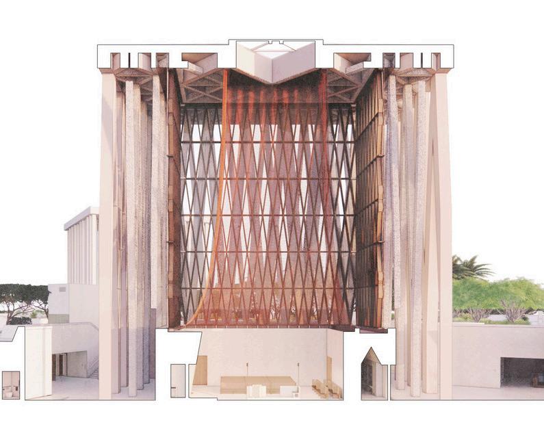
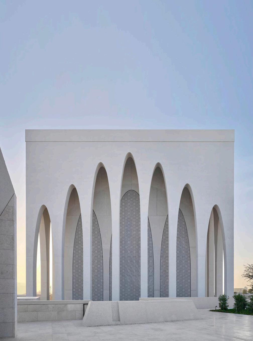
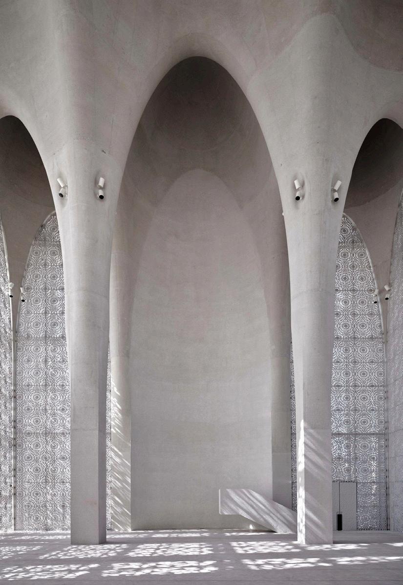
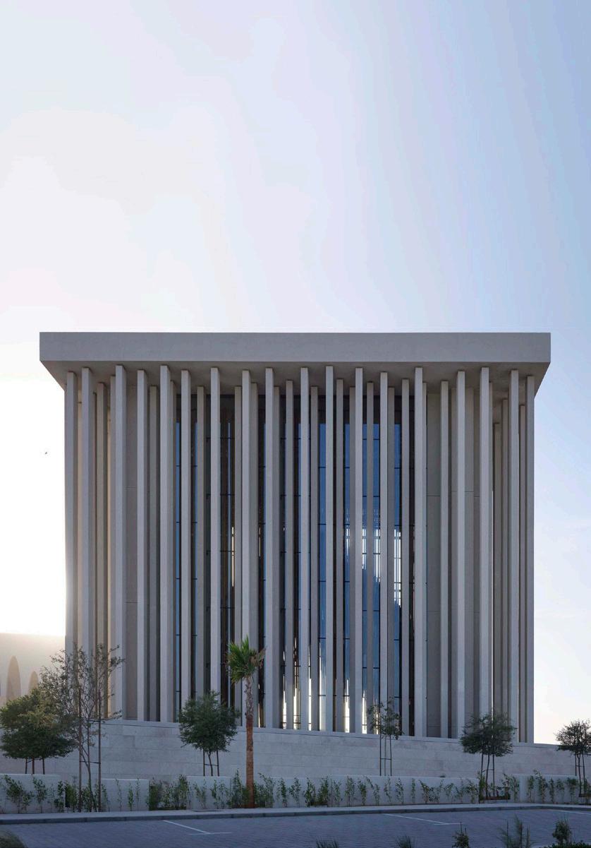
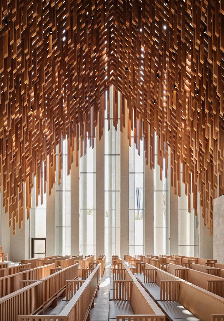
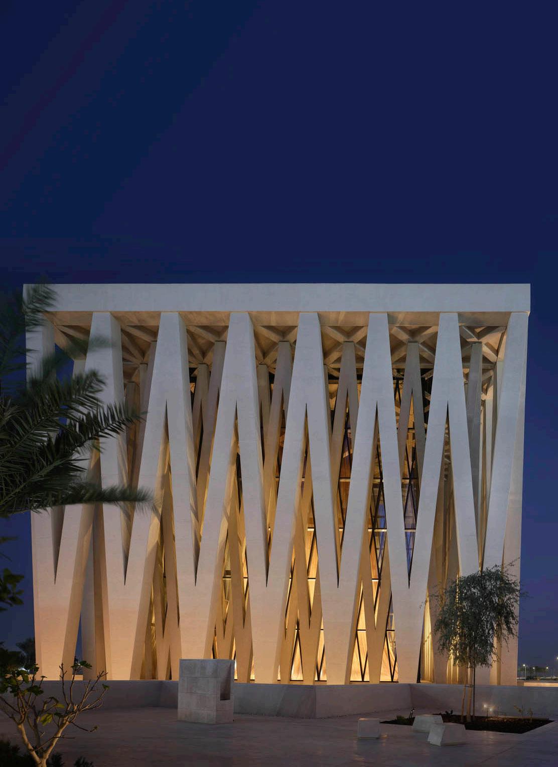
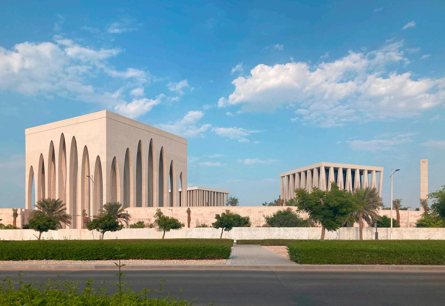
The Abrahamic Family House will be a collection of three religious spaces: a mosque, a synagogue and a church, all of which will sit upon a secular visitor pavilion. The house will serve as a community for inter-religious dialogue and exchange, nurturing the values of peaceful co-existence and acceptance among different beliefs, nationalities and cultures. Within each of the houses of worship, visitors will have the opportunity to observe religious services, listen to holy scripture, and experience sacred rituals. The fourth space — not affiliated with any specific religion — will serve as a center for all people of goodwill to come together as one. The community will also offer educational and event-based programming.
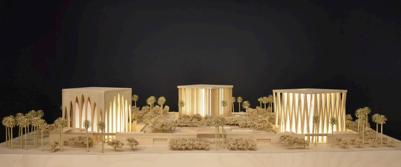
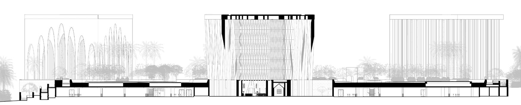
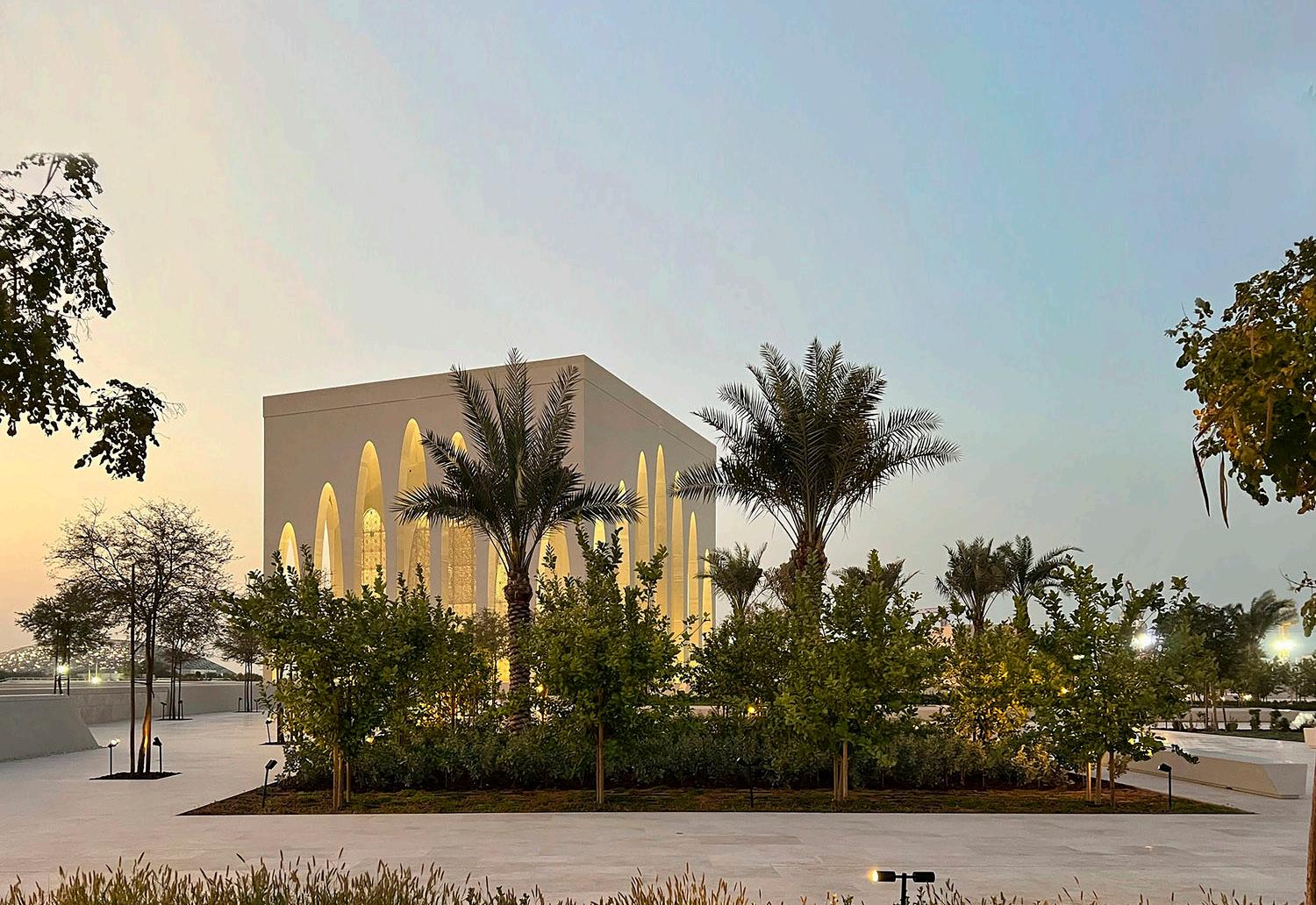
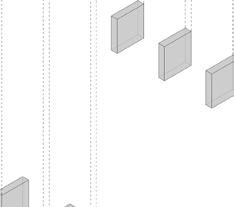
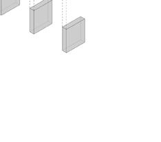
The form is translated from the three faiths, carefully using the lens to define what is similar as opposed to what is different, and using the power of these revelations to make the form. The design appears as powerful plutonic forms with a clear geometry, three cubes sitting on a plinth – though not aligned, they each have different orientations. The story then starts to become apparent through the power of the silhouette, unified with commonality and the articulation of the three forms. These structures represent a safe space, each volume illustrated with colonnades, screens and vaults to represent the sacred nature.
The discovery continues with the common ground, the public space in-between, where the difference connects. The garden is used as a powerful metaphor, a safe space where community, connection and civility combine – this space exists between the three chambers, the three faiths. The podium allows you to interact with each space with no preventative threshold, to dissolve the perceptions of not being included and encourage the celebration of this collective history and collective identity.
10
11
12
13
14
15
16

17


18 Adjaye Associates SINCE 1875 JAMES L WILLIAMS MIDDLE EAST KEY PLAN: DESIGN & BUILD CONTRACTOR: ARCHITECT OF RECORD: PROJECT NAME: B1N-2020-000452 PROJECT DESCRIPTION: ZONE: SAADIYAT ISLAND SDN8 P44 DESIGN OF CULTURAL CENTERS FOR WORSHIP ON SAADIYAT ISLAND PROJECT CORDOBA ABRAHAMIC FAMILY HOUSE THIS DOCUMENTATION CONTAINS INTELLECTUAL PROPERTY MATERIAL, CONFIDENTIAL INFORMATION AND OR PROPRIETARY INFORMATION OF MIRAL ASSET MANAGEMENT L.L.C. A0 PART 3 QUIBLA N P.O. Box 53 International Tower, Capital Gate Abu Dhabi, United Arab Emirates Facsimile +971 2 613 4001 ADJAYE ASSOCIATES The Edison 223 -231 Old Marylebone Road London, NW1 5QT, United Kingdom Phone +44 (0)20 7258 6140 EMPLOYER CONFIDENTIALITY REQUIREMENTS. DO NOT SCALE FROM THIS DRAWING. ARCHITECTURAL, STRUCTURAL, MECHANICAL AND ELECTRICAL DRAWINGS AND THE LEVELS SHOWN ON THE DRAWING ARE NEW ABU DHABI DATUM (NADD) LEVELS. GENERAL NOTES: EMPLOYER: P.O. Box 147774 HQ Building, Al-Raha Blvd Road Abu Dhabi, United Arab Emirates Facsimile +971 4068899 PO Box 112978 Otaiba Tower, Zayed 1st Street, 3/F-304 Abu Dhabi, United Arab Emirates Facsimile + 971 2 6348614 ENGINEER: Business Avenue Tower Abu Dhabi, United Arab Emirates Design Consultancy 1 100 D2 GA CHURCH SECTIONS (FOH ARCH) 08/10/2020 YB/TG AA AR-141300 AFH-AAA-CHU-ZZ-DR-AR-141300 CHURCH -E/W SECTION 1 CHURCH -N/S SECTION 2 SUSPENDED TIMBER BATTENS SYSTEM HAMMERED CONCRETE COLUMN EXTERNAL BUSH HAMMERED CONCRETE PARAPET EXTERNAL BUSH HAMMERED D050% GATEWAY STAGE 3+4 SUBMISSION26/07/2020 D1100% GATEWAY STAGE 3+4 SUBMISSION24/09/2020 D2100% GATEWAY STAGE 3+4 SUBMISSION08/10/2020 OMAN STONE ENTRANCE Adjaye Associates SINCE 1875 KEY PLAN: OFFICIAL USE ONLY: DESIGN & BUILD CONTRACTOR: ARCHITECT OF RECORD: LEAD ARCHITECT: PROJECT NAME: B1N-2020-000452 PROJECT ID: DRAWING NO: SHEET NO: SUBMISSION DATE: PROJECT DESCRIPTION: SAADIYAT SDN8 DESIGN OF CULTURAL WORSHIP ON SAADIYAT PROJECT ABRAHAMIC FAMILY THIS DOCUMENTATION CONTAINS INTELLECTUAL INFORMATION AND OR PROPRIETARY INFORMATION 1. THIS DRAWING INCLUDING THE INTELLECTUAL EMPLOYER CONFIDENTIALITY REQUIREMENTS. 3. DO NOT SCALE FROM THIS DRAWING. ARCHITECTURAL, STRUCTURAL, MECHANIC ALL RELEVANT SECTIONS OF THE SPECIFICATIONS. 5. THE LEVELS SHOWN ON THE DRAWING ARE GENERAL NOTES: EMPLOYER: ENGINEER: Design GA CHURCH SECTIONS ARCH) 08/10/2020 AA AR-141300 AFH-AAA-CHU-ZZ-DR-AR-141300 100 CHURCH -E/W SECTION 1 100 CHURCH -N/S SECTION 2 SUSPENDED SOLID TIMBER SYSTEM HAMMERED CONCRETE SUSPENDED TIMBER SYSTEM HAMMERED CONCRETE COLUMN EXTERNAL BUSH HAMMERED EXTERNAL BUSH HAMMERED EXTERNAL BUSH HAMMERED EXTERNAL BUSH HAMMERED D050% GATEWAY STAGE D1100% GATEWAY STAGE D2100% GATEWAY STAGE OMAN STONE ENTRANCE COLUMN JOINT LOCATIONS STONE SETTING OUT POINT STONE SETTING OUT POINT 16 16 17 17 18 18 19 19 20 20 21 21 22 22 23 23 H H G G F F E E D D C C B B A A C1 C1 C2 C2 C3 C3 C4 C4 C5 C5 C6 C6 C7 C7 C8 C8 CH CH CG CG CF CF CE CE CD CD CC CC CB CB CA CA 141201 1 141300 142500 142701 8,500 8,500 8,500 8,500 8,500 8,500 4,250 8,500 8,500 8,500 8,500 8,500 8,500 9,875 WATER FEATURE WELCOME CENTRE CAR PARK CHURCH ENTRANCE VOID ABOVE VOID ABOVE COURTYARD ENTRANCE RESIDENCE ENTRANCE WATER FEATURE VOID ABOVE CHU-G06 WORSHIP SPACE 17 m² CHU-G03 53 m² CHU-G02 BAPTISTRY 22 m² 23 m² CHU-G13 MALE WC VESTIBULE 6,150 14 m² CHU-G17 27 m² CHU-G15 VOID ABOVE 18 m² CHU-G08 WC VESTIBULE KITCHEN POWDER ROOM m² CHU-G10 m² CHU-G12 m² m² BOH-G19 15 m² 16 m² BOH-G17 10 m² BOH-G24 WASTE ROOM EXTERNAL ROOM 6,150 6,150 6,150 6,150 6,150 6,150 6,315 CHU-01b CHU-G07 CHU-G12 CHU-G11 CHU-G10 CHU-G14a CHU-G16 CHU-G20 CHU-G19 CHU-G17a CHU-G20a CHU-G04a CHU-G05 CHU-G06 CHU-G02 SECURITY ENTRANCE 1,275 CHU-G08 EXTERNAL COURTYARD EXTERNAL COURTYARD 52 m² SERVICE CORRIDOR BOH-G22 BOH-G25 1,475 1,475 1,923 501 1,758 3,755 4,250 1,923 500 6,550 2,450 4,425 700 800 1,450 500 4,737 3,899 2,300 1,250 2,873 2,524 358 707 300 1,322 1,502 1,501 18 2,409 350 600 2,405 450 4,663 1,500 1,650 1,345 SANCTUARY 6,150 6,150 6,000 6,150 6,150 6,150 6,150 6,000 6,150 6,150 6,150 CHU-G17 CHU-G06a TRANCEPT EXIT TRANCEPT EXIT1 6,150 6,150 6,000 LEGEND FACADE SETTING OUT SETTING OUT NORTH/SOUTH AND EAST/WEST SETTING OUT NORTH/SOUTH OR EAST/WEST BALUSTRADE SETTING OUT 1 100 CHURCH -GROUND FLOOR PLAN 1 05 Stage 4 Drawings Packages 0 FFL 11,050 FFL ROOF 35,800 FFL C1 C2 C3 C4 C5 C6 C7 C8 29,650 SERVICE ACCESS GANTRY 6,150 FFL WATER FEATURE 1,100 600 12,250 11,100 WORSHIP SPACE 12,250 MAIN ENTRANCE SANCTUARY 9,705 FFL MEP MAINTENANCE PLATFORM 0 FFL 11,050 FFL ROOF 35,800 FFL CH CG CF CE CD CC CB CA 141300 4,100 4,100 4,100 4,100 4,100 4,100 4,100 29,650 SERVICE ACCESS GANTRY 6,150 FFL 1,100 600 12,250 11,100 384 m² 9,705 FFL Adjaye Associates SINCE JAMES L WILLIAMS EAST DESIGN ARCHITECT OF PROJECT NAME: B1N-2020-000452 DRAWING TITLE: PROJECT DESCRIPTION: ZONE: ISLAND SDN8 OF CULTURAL ON ISLAND ABRAHAMIC HOUSE DOCUMENTATION CONTAINS PROPERTY MATERIAL, AND OF ASSET MANAGEMENT A0 3 QUIBLA N P.O. Box International Tower, Gate United Arab Emirates Facsimile 613 4001 The 223 Old Marylebone NW1 5QT, United Phone +44 7258 1. THIS DRAWING INCLUDING THE INTELLECTUAL PROPERTY RIGHTS AND THE COPY REQUIREMENTS. 3. DO SCALE 4. THIS DRAWING MUST BE READ IN CONJUNCTION WITH OTHER RELEVANT STRUCTURAL, MECHANIC ALL RELEVANT SECTIONS OF THE SPECIFICATIONS. 5. THE LEVELS SHOWN ON THE DRAWING ARE ABU DHABI (NADD) LEVELS. GENERAL EMPLOYER: P.O. 147774 HQ Building, Al-Raha Blvd Abu Arab Emirates Facsimile +971 4068899 Box 112978 Otaiba Zayed 3/F-304 Abu Dhabi, United Arab ENGINEER: Avenue Abu Dhabi, United Emirates Phone 971 566 4000 Design Consultancy 1 GA CHURCH SECTIONS (FOH 08/10/2020 YB/TG AA AFH-AAA-CHU-ZZ-DR-AR-141300 CHURCH SECTION 1 CHURCH 2 SUSPENDED SOLID TIMBER SYSTEM HAMMERED CONCRETE TIMBER CONCRETE EXTERNAL EXTERNAL EXTERNAL BUSH HAMMERED EXTERNAL BUSH HAMMERED GATEWAY 3+4 SUBMISSION26/07/2020 D1100% STAGE 3+4 D2100% STAGE 3+4 COLUMN JOINT LOCATIONS UNDER REVIEW 0 FFL 11,050 FFL ROOF 35,800 FFL C1 C2 C3 C4 C5 C6 C7 C8 29,650 SERVICE ACCESS GANTRY 6,150 FFL WATER FEATURE 1,100 600 12,250 11,100 12,250 MAIN ENTRANCE SANCTUARY MEP MAINTENANCE PLATFORM 0 FFL 11,050 FFL ROOF 35,800 FFL CH CG CF CE CD CC CB CA 4,100 4,100 4,100 4,100 4,100 4,100 4,100 29,650 SERVICE ACCESS GANTRY 6,150 FFL 1,100 600 12,250 11,100 MEP MAINTENANCE PLATFORM Adjaye Associates SINCE 1875 JAMES L WILLIAMS MIDDLE EAST DESIGN BUILD CONTRACTOR: ARCHITECT OF RECORD: LEAD ARCHITECT: PROJECT NAME: B1N-2020-000452 PROJECT DESCRIPTION: ZONE: SAADIYAT ISLAND SDN8 P44 DESIGN OF CULTURAL CENTERS FOR WORSHIP ON SAADIYAT ISLAND PROJECT CORDOBA ABRAHAMIC FAMILY HOUSE THIS DOCUMENTATION CONTAINS INTELLECTUAL PROPERTY MATERIAL, CONFIDENTIAL INFORMATION AND OR PROPRIETARY INFORMATION OF MIRAL ASSET MANAGEMENT L.L.C. A0 PART 3 QUIBLA N P.O. Box 53 International Tower, Capital Gate Abu Dhabi, United Arab Emirates The Edison 223 -231 Old Marylebone Road London, NW1 5QT, United Kingdom Phone +44 (0)20 7258 6140 1. THIS DRAWING INCLUDING THE INTELLECTUAL PROPERTY RIGHTS AND THE COPY EMPLOYER CONFIDENTIALITY REQUIREMENTS. 2. ALL DIMENSIONS ARE IN METRIC MM UNLESS NOTED OTHERWISE. 4. THIS DRAWING MUST BE READ IN CONJUNCTION WITH OTHER RELEVANT ARCHITECTURAL, STRUCTURAL, MECHANIC ALL RELEVANT SECTIONS OF THE SPECIFICATIONS. 5. THE LEVELS SHOWN ON THE DRAWING ARE NEW ABU DHABI DATUM (NADD) LEVELS. GENERAL NOTES: EMPLOYER: P.O. Box 147774 HQ Building, Al-Raha Blvd Road Abu Dhabi, United Arab Emirates Facsimile +971 4068899 www.miral.ae PO Box 112978 Otaiba Tower, Zayed 1st Street, 3/F-304 Abu Dhabi, United Arab Emirates Phone 971 2 6344039 ENGINEER: Zone 1E11 Abu Dhabi, United Arab Emirates Phone 971 566 4000 Design Consultancy built assets 1 100 D2 GA CHURCH SECTIONS (FOH ARCH) 08/10/2020 YB/TG AA AR-141300 AFH-AAA-CHU-ZZ-DR-AR-141300 CHURCH -E/W SECTION 1 CHURCH -N/S SECTION 2 SUSPENDED SOLID TIMBER CURTAIN WALL SYSTEM EXTERNAL BUSH HAMMERED CONCRETE SUSPENDED TIMBER CURTAIN WALL SYSTEM EXTERNAL BUSH HAMMERED CONCRETE COLUMN EXTERNAL BUSH EXTERNAL BUSH CONCRETE SOFFIT EXTERNAL BUSH EXTERNAL BUSH CONCRETE SOFFIT D050% GATEWAY STAGE 3+4 SUBMISSION26/07/2020 D1100% GATEWAY STAGE 3+4 SUBMISSION24/09/2020 OMAN STONE ENTRANCE COLUMN JOINT LOCATIONS UNDER REVIEW 0 FFL 11,050 FFL ROOF 35,800 FFL C1 C2 C3 C4 C5 C6 C7 C8 29,650 SERVICE ACCESS GANTRY 6,150 FFL WATER FEATURE 1,100 600 12,250 11,100 WORSHIP SPACE 12,250 MAIN ENTRANCE SANCTUARY 9,705 FFL MEP MAINTENANCE PLATFORM 0 FFL 11,050 FFL ROOF 35,800 FFL CH CG CF CE CD CC CB CA 141300 4,100 4,100 4,100 4,100 4,100 4,100 4,100 29,650 SERVICE ACCESS GANTRY 6,150 FFL 1,100 600 12,250 11,100 384 m² 9,705 FFL Adjaye SINCE 1875 DESIGN & BUILD CONTRACTOR: ARCHITECT OF RECORD: PROJECT NAME: B1N-2020-000452 DRAWING TITLE: PROJECT DESCRIPTION: ZONE: SAADIYAT SDN8 DESIGN OF WORSHIP ON SAADIYAT PROJECT ABRAHAMIC FAMILY THIS DOCUMENTATION CONTAINS INTELLECTUAL INFORMATION AND OR PROPRIETARY INFORMATION 1. THIS DRAWING INCLUDING THE INTELLECTUAL EMPLOYER CONFIDENTIALITY REQUIREMENTS. 3. DO NOT SCALE FROM THIS DRAWING. 4. THIS DRAWING MUST BE READ IN CONJUNCTION ARCHITECTURAL, STRUCTURAL, MECHANIC ALL RELEVANT SECTIONS OF THE SPECIFICATIONS. 5. THE LEVELS SHOWN ON THE DRAWING GENERAL NOTES: EMPLOYER: ENGINEER: Design GA CHURCH SECTIONS ARCH) 08/10/2020 AA AR-141300 CHURCH -E/W SECTION CHURCH -N/S SECTION 2 CONCRETE COLUMN BUSH BUSH D050% GATEWAY STAGE D1100% GATEWAY STAGE D2100% GATEWAY STAGE UNDER REVIEW STONE SETTING OUT POINT 16 16 17 17 18 18 19 19 20 20 21 21 22 22 23 23 H H G G F F E E D D C C B B A A C1 C1 C2 C2 C3 C3 C4 C4 C5 C5 C6 C6 C7 C7 C8 C8 CH CH CG CG CF CF CE CE CD CD CC CC CB CB CA CA 141200 141201 1 141300 1 8,500 8,500 8,500 8,500 8,500 8,500 4,250 8,500 8,500 8,500 8,500 8,500 8,500 9,875 WATER FEATURE WELCOME CENTRE CAR PARK CHURCH ENTRANCE VOID ABOVE VOID ABOVE COURTYARD ENTRANCE RESIDENCE ENTRANCE WATER FEATURE VOID ABOVE CHU-G04 CONFESSION 384 m² CHU-G06 53 m² 23 m² 25 m² WEL-G37 VESTIBULE 6,150 STORAGE 27 m² VOID ABOVE JANITORS CLOSET 11 m² CHU-G08 CHU-G05 ACCESS STAIRWELL CHU-G14 KITCHEN CHU-G16 POWDER ROOM CHU-G20 BEDROOM ENSUITE m² PLUMBING PLANT ROOM HVAC PLANT ROOM 10 m² EXTERNAL ROOM 6,150 6,150 6,150 6,150 6,150 6,150 6,315 CHU-01b CHU-G01a CHU-G07 CHU-G12 CHU-G11 CHU-G10 CHU-G14a CHU-G16 CHU-G17a CHU-G20a CHU-G04 CHU-G04a CHU-G22 CHU-G06 CHU-G02 81 m² CHU-G00 SECURITY ENTRANCE 1,275 CHU-G08 EXTERNAL COURTYARD EXTERNAL COURTYARD AIR HANDLING UNITS SERVICE CORRIDOR 11 m² BOH-G22 66 m² BOH-G23 79 m² BOH-G25 m² BOH-G26 1,475 1,475 1,923 501 1,758 3,755 4,250 1,923 500 6,550 2,450 4,425 700 800 1,450 500 4,737 3,899 2,300 1,250 2,873 2,524 358 707 300 1,322 1,502 1,501 18 2,409 350 600 2,405 450 4,663 1,500 1,650 1,345 SANCTUARY 6,150 6,150 6,000 6,150 6,150 6,150 6,150 6,000 6,150 6,150 6,150 CHU-G18 TRANCEPT EXIT TRANCEPT EXIT2 6,150 6,150 6,000 LEGEND FACADE SETTING OUT SETTING OUT NORTH/SOUTH AND EAST/WEST SETTING OUT NORTH/SOUTH OR EAST/WEST BALUSTRADE SETTING OUT CHURCH -GROUND FLOOR PLAN 1 05 00 0 FFL PODIUM 11,050 FFL ROOF 35,800 FFL C1 C2 C3 C4 C5 C6 C7 C8 2 29,650 GROUND FLOOR FFL 6,150 FFL 1,100 600 12,250 11,100 13 m² 12,250 MEP MAINTENANCE PLATFORM 9,705 FFL 00 0 FFL PODIUM 11,050 FFL ROOF 35,800 FFL CH CG CF CE CD CC CB CA 4,100 4,100 4,100 4,100 4,100 4,100 4,100 29,650 SERVICE ACCESS GANTRY GROUND FLOOR FFL 6,150 FFL 1,100 600 12,250 11,100 CHU-G06 WORSHIP SPACE MEP MAINTENANCE PLATFORM 9,705 FFL Adjaye Associates SINCE 1875 KEY PLAN: MEP DESIGN & BUILD CONTRACTOR: B1N-2020-000452 PROJECT ID: DRAWING NO: SHEET NO: SUBMISSION DATE: DRAWN BY: DRAWING TITLE: SECTION NO: SAADIYAT SDN8 DESIGN OF CULTURAL WORSHIP ON SAADIYAT PROJECT ABRAHAMIC FAMILY THIS DOCUMENTATION CONTAINS INTELLECTUAL RIGHTS SHALL REMAIN AS THE PROPERTY EMPLOYER CONFIDENTIALITY REQUIREMENTS. 3. DO NOT SCALE FROM THIS DRAWING. ARCHITECTURAL, STRUCTURAL, MECHANIC 5. THE LEVELS SHOWN ON THE DRAWING GA CHURCH SECTIONS ARCH) 08/10/2020 AA AR-141300 AFH-AAA-CHU-ZZ-DR-AR-141300 100 CHURCH -E/W SECTION 1 1 100 CHURCH -N/S SECTION 2 SOLID TIMBER BATTENS CURTAIN WALL EXTERNAL BUSH CONCRETE COLUMN TIMBER BATTENS CURTAIN WALL EXTERNAL BUSH CONCRETE COLUMN HAMMERED CONCRETE PARAPET HAMMERED CONCRETE SOFFIT HAMMERED CONCRETE PARAPET HAMMERED CONCRETE SOFFIT REV DESCRIPTION D050% GATEWAY STAGE D1100% GATEWAY STAGE D2100% GATEWAY STAGE ENTRANCE VESTIBULE COLUMN JOINT UNDER REVIEW FFL 11,050 FFL ROOF 35,800 FFL C1 C2 C3 C4 29,650 SERVICE ACCESS GANTRY 6,150 FFL WATER FEATURE 1,100 600 12,250 11,100 WORSHIP SPACE 12,250 MAIN ENTRANCE SANCTUARY 9,705 FFL MEP MAINTENANCE PLATFORM 0 FFL 11,050 FFL ROOF 35,800 FFL CH CF CD 141300 4,100 4,100 4,100 29,650 SERVICE ACCESS GANTRY 6,150 FFL 1,100 600 12,250 11,100 384 m² 9,705 FFL Adjaye Associates SINCE 1875 JAMES L WILLIAMS MIDDLE EAST DESIGN & BUILD CONTRACTOR: ARCHITECT OF RECORD: PROJECT NAME: B1N-2020-000452 DRAWING TITLE: PROJECT DESCRIPTION: ZONE: SAADIYAT ISLAND SDN8 P44 DESIGN OF CULTURAL CENTERS WORSHIP ON SAADIYAT ISLAND PROJECT CORDOBA ABRAHAMIC FAMILY HOUSE THIS DOCUMENTATION CONTAINS INTELLECTUAL PROPERTY MATERIAL, CONFIDENTIAL INFORMATION AND OR PROPRIETARY INFORMATION OF MIRAL ASSET A0 PART QUIBLA P.O. Box International Tower, Abu Dhabi, United Arab Facsimile +971 2 ADJAYE ASSOCIATES The Edison 223 -231 Old Marylebone London, NW1 5QT, United Phone +44 (0)20 7258 THIS DRAWING INCLUDING THE INTELLECTUAL RIGHTS AND EMPLOYER CONFIDENTIALITY REQUIREMENTS. DO NOT SCALE FROM THIS DRAWING. THIS DRAWING MUST BE READ IN CONJUNCTION WITH OTHER RELEVANT ARCHITECTURAL, STRUCTURAL, MECHANIC ALL RELEVANT SECTIONS OF THE SPECIFICATIONS. THE LEVELS SHOWN ON THE DRAWING ARE NEW ABU DHABI DATUM (NADD) GENERAL NOTES: EMPLOYER: P.O. Box 147774 HQ Building, Al-Raha Abu Dhabi, United Facsimile +971 PO Box 112978 Otaiba Tower, Zayed 1st Abu Dhabi, United Arab ENGINEER: Business Avenue Abu Dhabi, United Phone 971 Design Consultancy 1 100 GA CHURCH SECTIONS (FOH ARCH) 08/10/2020 YB/TG AA AR-141300 AFH-AAA-CHU-ZZ-DR-AR-141300 CHURCH -E/W SECTION 1 CHURCH -N/S 2 SUSPENDED SOLID TIMBER SYSTEM HAMMERED CONCRETE SUSPENDED TIMBER SYSTEM HAMMERED CONCRETE COLUMN EXTERNAL BUSH HAMMERED EXTERNAL BUSH HAMMERED EXTERNAL BUSH HAMMERED EXTERNAL BUSH HAMMERED D050% GATEWAY STAGE 3+4 SUBMISSION26/07/2020 D1100% GATEWAY STAGE 3+4 SUBMISSION24/09/2020 D2100% GATEWAY STAGE 3+4 SUBMISSION08/10/2020 OMAN STONE ENTRANCE COLUMN JOINT LOCATIONS UNDER REVIEW
19 C1 C2 C3 C4 C5 C6 C7 C8 CH CG CF CE CD CC CB CA 141201 142015 142015 142020 CHU-G06 BLK-112 3,462 2,008 3,470 6,315 6,150 6,150 6,150 EWS-211 384 m² CHU-G06 WORSHIP SPACE 17 m² CONFESSION m² CHU-G05 FLH-221 LIN-101 IWS-111 LIN-101 IWS-111 142017 147501 147503 1 147504 147507 1 147508 CHU-G06a 143101 SANCTUARY 23 1 3 CON-201 EWS-211 BLK-112 LIN-761 CON-201 CON-201 CON-201 CON-201 CON-201 CON-201 1 220 2 0 1 220 2 CLEARROUTE C E R ROU E C EARROUTE C E A R R O U T HVAC SUPPY STACK HVAC SUPPY STACK HVAC SUPPY STACK HVAC SUPPY STACK HVAC SUPPY GRILLES 1,513 3,513 1,375 1,450 800 1,375 1,450 800 1,500 1,500 600 776 400 800 3,299 1,581 2,000 2,020 1,505 1,025 1 00 00 1,625 2,000 2,001 1,624 800 774 800 400 1,041 1,051 250 575 500 249 574 502 2,000 1,666 2,001 1,623 573 577 573 1,500 ALIGN ALIGN ALIGN ALIGN EDGE OF ROOF ABOVE 1700 1,409 199 6,150 6,150 6,150 RWP RWP RWP RWP 2 302 300 4 1,500 1,500 Adjaye KEY PLAN: OFFICIAL USE DESIGN & BUILD ARCHITECT LEAD ARCHITECT: PROJECT NAME: B1N-2020-000452 PROJECT ID: DRAWING NO: SHEET NO: SUBMISSION DRAWING TITLE: PROJECT DESCRIPTION: SECTION NO: ZONE: DESIGN WORSHIP ABRAHAMIC THIS DOCUMENTATION 1. THIS DRAWING RIGHTS SHALL EMPLOYER 4. THIS DRAWING ARCHITECTURAL, ALL RELEVANT 5. THE LEVELS GENERAL NOTES: EMPLOYER: ENGINEER: ENLARGED 24/09/2020 AFH-AAA-CHU-00-DR-AR-142001 1 50 ENLARGED CHURCH GROUND FLOOR PLAN 1 SUPPLY AIR GRILLES PULPIT ALTAR CREDENCE TABLE D0100% Stage 4 Drawings Packages Adjaye Associates SAADIYAT ISLAND SDN8 P44 DESIGN OF CULTURAL CENTERS FOR WORSHIP ON SAADIYAT ISLAND SINCE 1875 JAMES L WILLIAMS MIDDLE EAST REV DESCRIPTION DATE PART 1 PART 3 PART 2 PART 4 PART 6 PART 5 QUIBLA N International Tower, Capital Gate Abu Dhabi, United Arab Emirates 223 231 Old Marylebone Road London, NW1 5QT, United Kingdom Phone +44 (0)20 7258 6140 1. THIS DRAWING INCLUDING THE INTELLECTUAL PROPERTY RIGHTS AND THE COPY RIGHTS SHALL REMAIN AS THE PROPERTY OF THE EMPLOYER AND SUBJECT TO THE EMPLOYER CONFIDENTIALITY REQUIREMENTS 2. ALL DIMENSIONS ARE IN METRIC MM UNLESS NOTED OTHERWISE. 3. DO NOT SCALE FROM THIS DRAWING. 4. THIS DRAWING MUST BE READ IN CONJUNCTION WITH OTHER RELEVANT ARCHITECTURAL, STRUCTURAL, MECHANICAL AND ELECTRICAL DRAWINGS AND ALL RELEVANT SECTIONS OF THE SPECIFICATIONS. 5. THE LEVELS SHOWN ON THE DRAWING ARE NEW ABU DHABI DATUM (NADD) LEVELS. MIRAL P.O. Box 147774 HQ Building, Al-Raha Blvd Road Abu Dhabi, United Arab Emirates Phone +971 2 4068888 Facsimile +971 4068899 www.miral.ae ZUBLIN CONSTRUCTION LLC PO Box 112978 Otaiba Tower, Zayed 1st Street, 3/F-304 Abu Dhabi, United Arab Emirates Phone + 971 6344039 Facsimile + 971 6348614 ARCADIS Abu Dhabi, United Arab Emirates EWS-120 CORNER PRECAST CLADDING HORIZONTAL DETAIL D0 75% GATEWAY STAGE 3+4 IN PROGRESS 27-08-2020 D1 24-09-2020 100% GATEWAY STAGE 3+4 SUBMISSION D2 12-11-2020 D2 D2 D2 D2
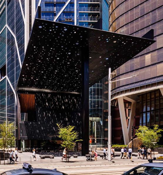
GEORGE STREET PLAZA BUILDING
(Competition, Winning Scheme)
1.200m2 Comunity Centre
Sydney, Australia
RIBA Stages 1- 6 (Built) 2019
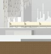
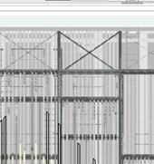
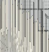
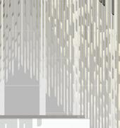
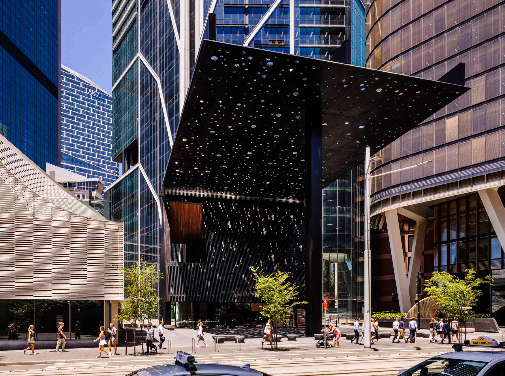
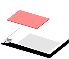
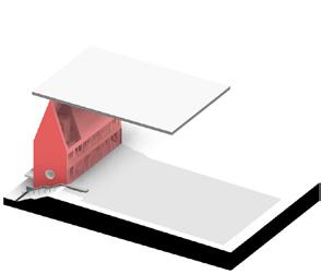
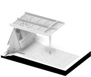
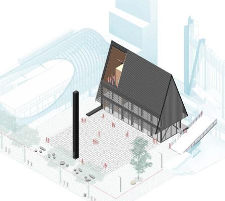
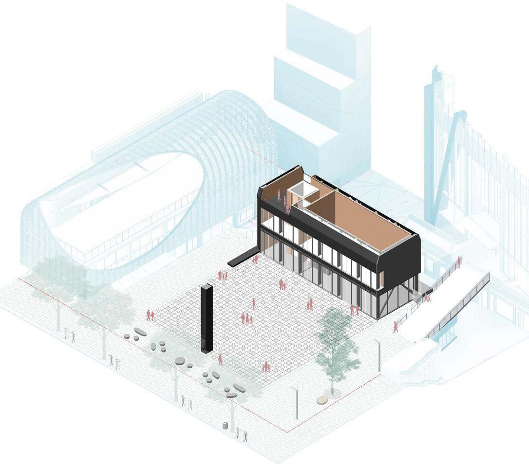
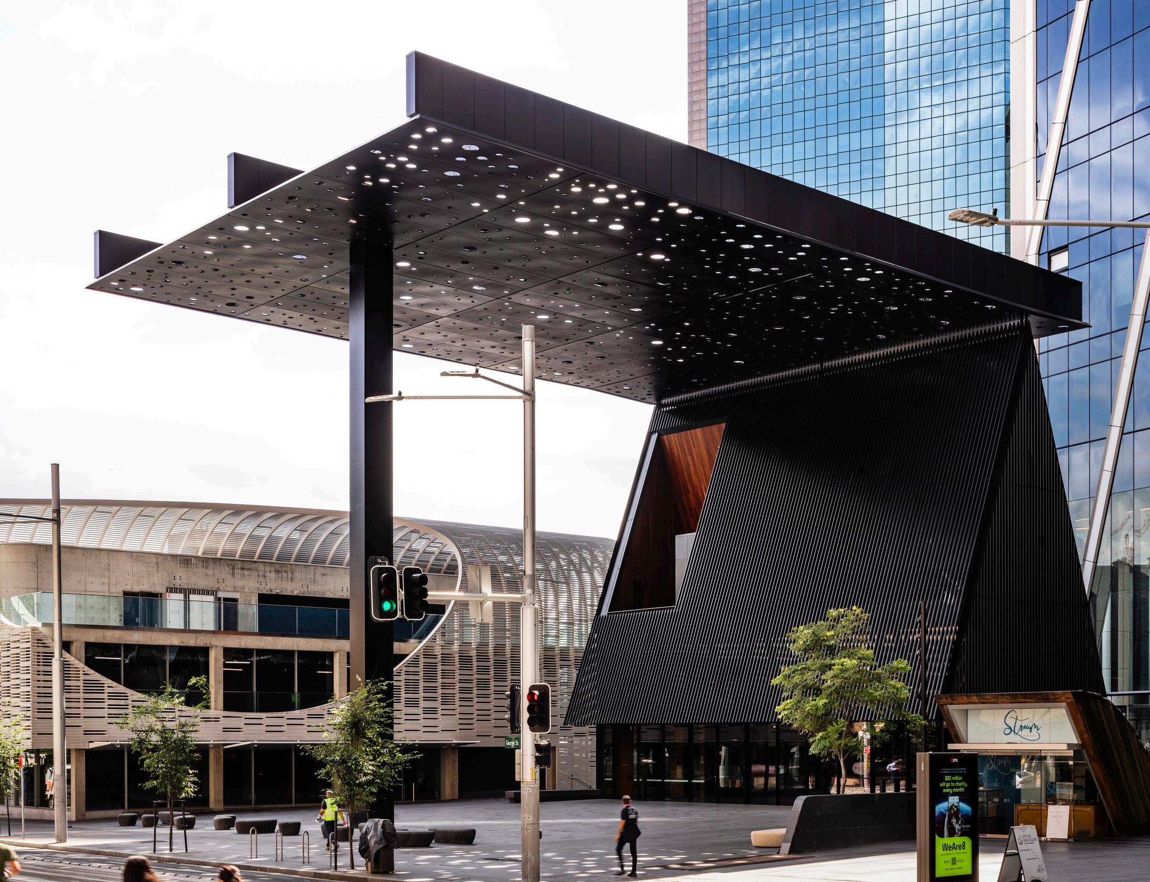
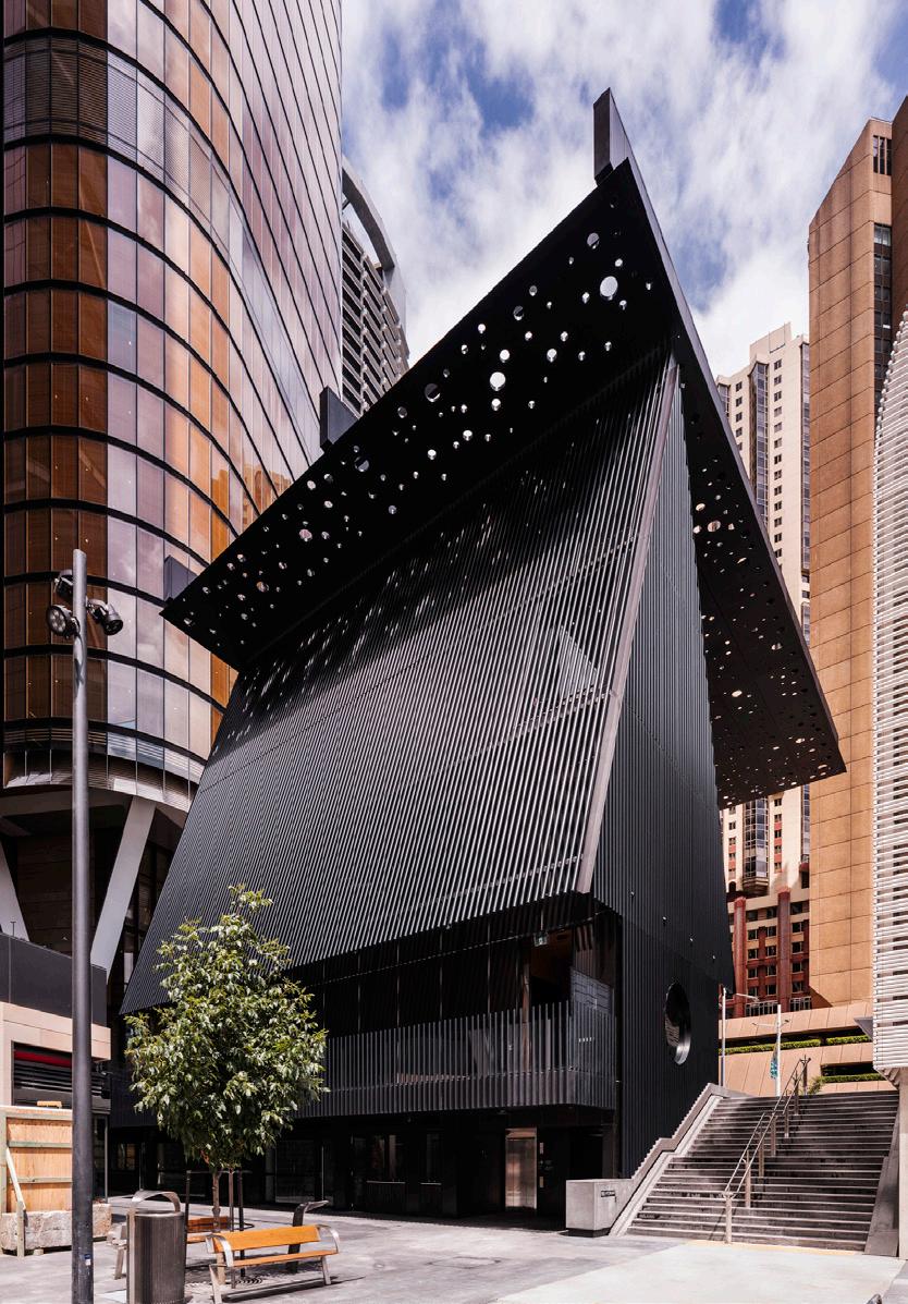
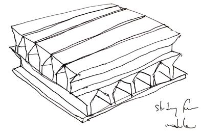
Inspired by simple unitary forms and place making in Aboriginal culture, the new community building and plaza are imagined as a ‘found place’ based around the notion of the shelter, a symbolic respite away from the busy streetscape, that is discovered and dissolves through light.
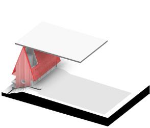
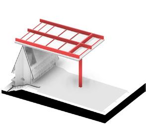
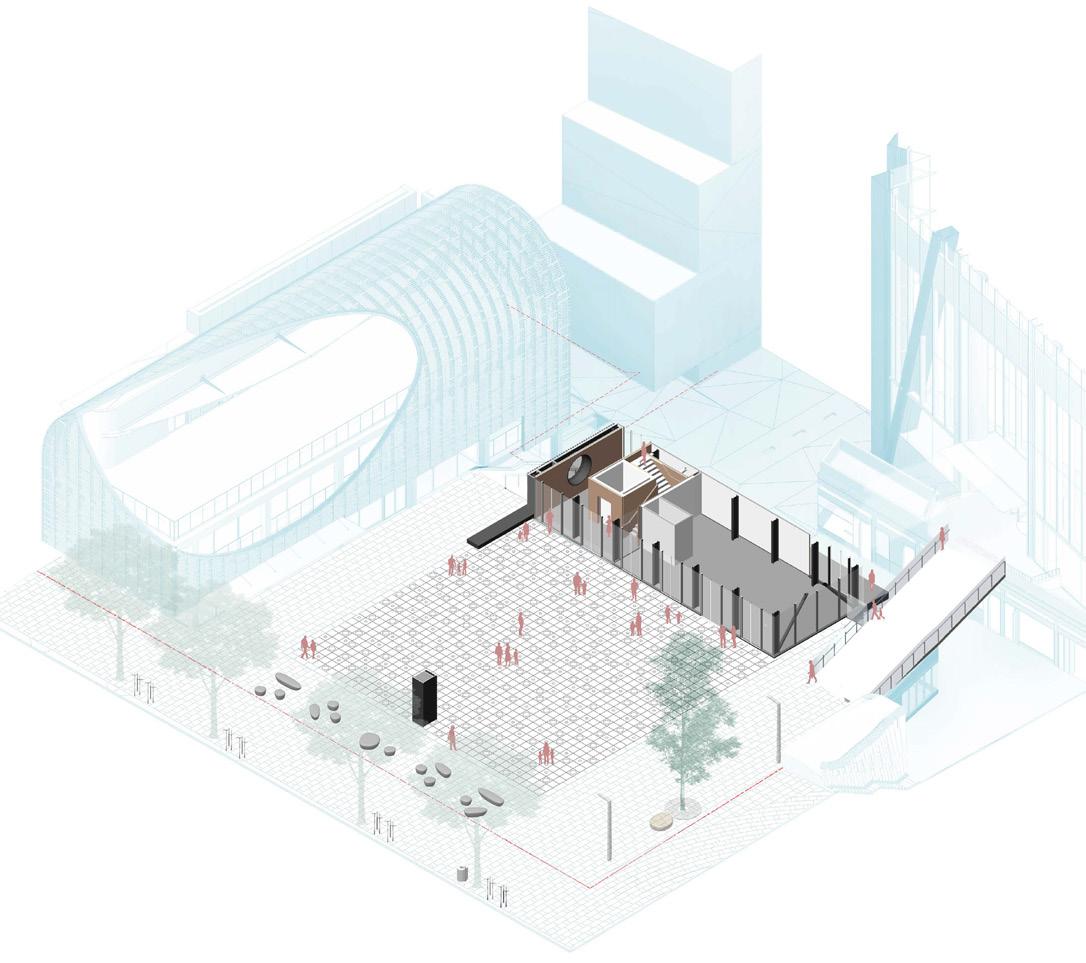
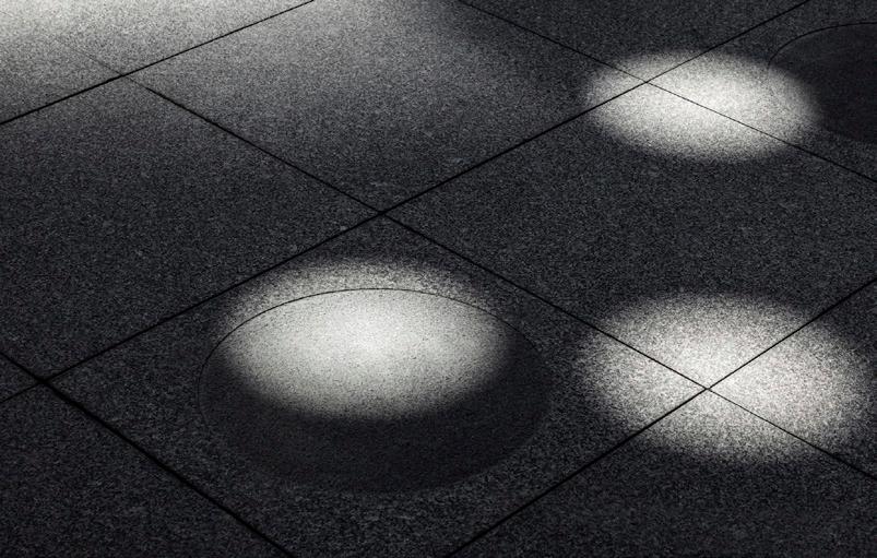
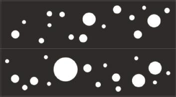
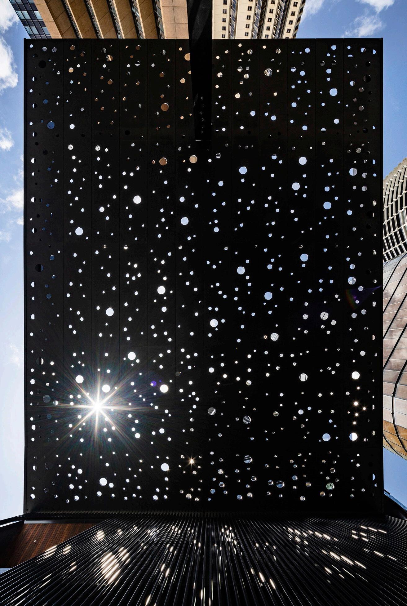
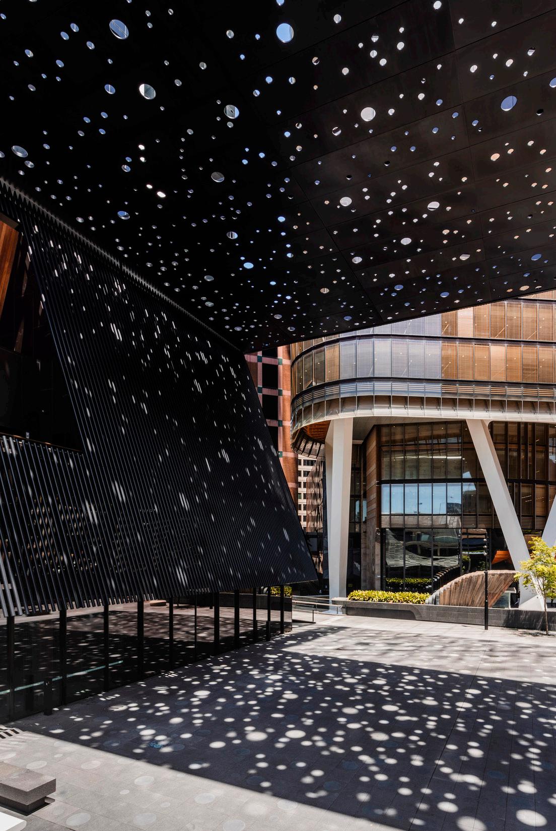
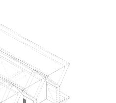
To connect this profound centre with the sites heritage and origins, Adjaye has collaborated with Daniel Boyd, a renowned contemporary artist of Aboriginal dissent, on the projects key feature – a 27x34m perforated canopy that shelters and unites the community building and the plaza under a poetic layer of light and darkness. Inspired by Aboriginal dot painting, Boyd will curate a cosmic journey of light that filters and refracts through multiple, randomly scattered, circular, mirrorlined canopy openings.
The community building’s details are intentionally simple. An open plan café, gallery space and garden terrace are wrapped under a reduced utilitarian form. It is a flexible and inviting, free flow space with activated connections to the plaza and adjacent developments, where encounters with art and community are made easy.
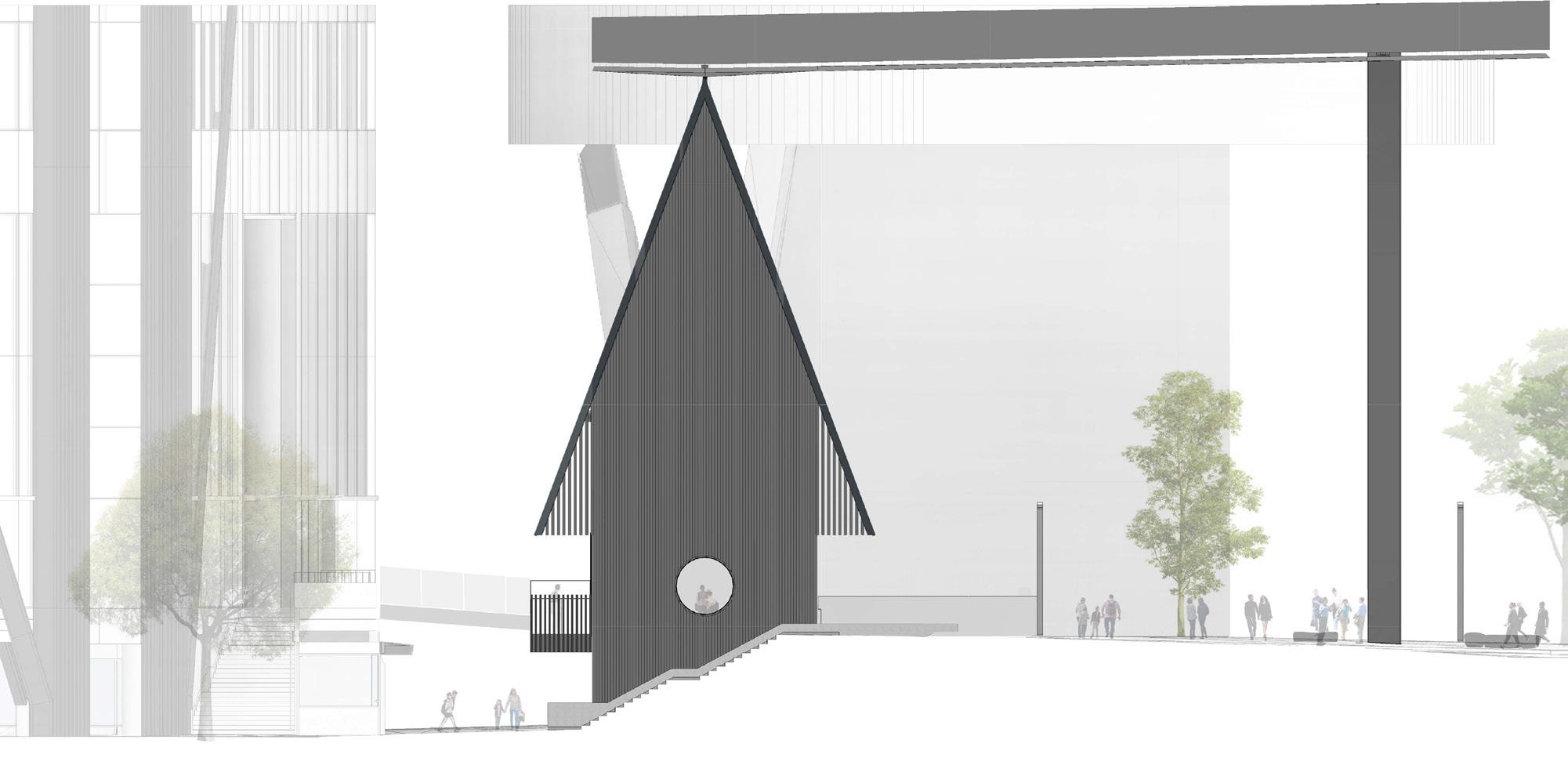
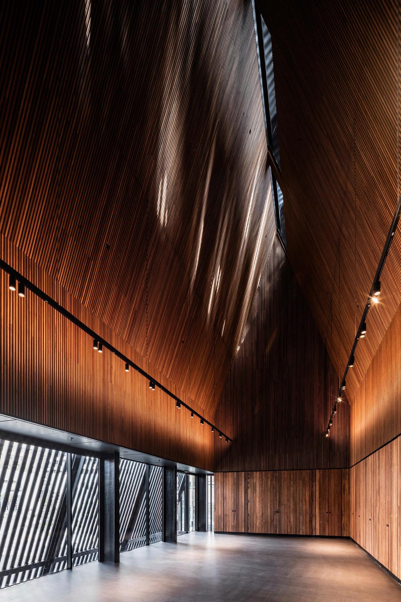
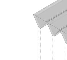
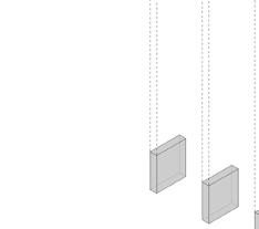
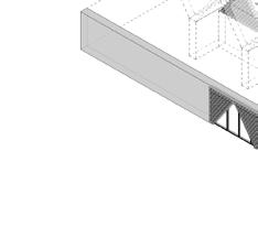
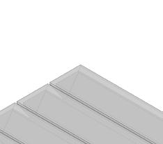
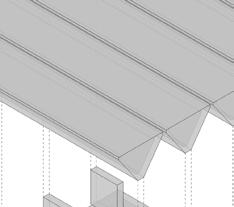
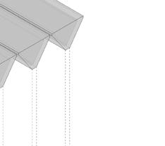
Rooted in lost history, the project is about the reconciliation of cultures and defining identity in an ever changing world. The distinctive pitched roof of the community building refers to the primary silhouette of early settlers’ houses – weaving in another layer to the narrative of place. The result is a hybrid form that merges the Aboriginal origins with the legacy of early settlers and the industrial materiality and language of the nearby harbour. This reconciliation of difference lies at the heart of the proposal and articulates our enthusiasm about issues of place and identity.
20
21 TENANCY SPACE CRANE LANE BELOW LOBBY LIFT STAIR

Site History: Eora & Cadigal
1. Mills Plains, John Glover 1835


Before the arrival of the first European settlers to Sydney in 1788, the Eora and Ku-Ring-Gai peoples occupied the traditional territories of Sydney known by its Aboriginal name Djubuguli. It is believed that as many as 29 clan groups made up the Eora peoples.
Before the arrival of the first European settlers to Sydney in 1788, the Eora and Ku-Ring-Gai peoples occupied the traditional territories of Sydney known by its Aboriginal name Djubuguli. It
The Wangal and the Cadigal people were the original custodians of the coastal lands and waters of what is now known as Port Jackson. The Cadigal
specifically occupied the area called “Cadi” that lies just south of Port
and what is today Sydney’s central business district.
The Wangal and the Cadigal people were the original custodians of the coastal lands and waters of what is now known as Port Jackson. The Cadigal clan specifically occupied the
The harbour was an important hunting, fishing and camping ground for the Eora people, and continues to be culturally significant.
The harbour was an important hunting, fishing and camping ground for the Eora people, and continues to be culturally significant.
As the town of Sydney developed into a city, the Gadigal were joined by other Aboriginal people from around New South Wales and Australia.
As the town of Sydney developed into a city, the Gadigal were joined by other Aboriginal people from around New South Wales and Australia.
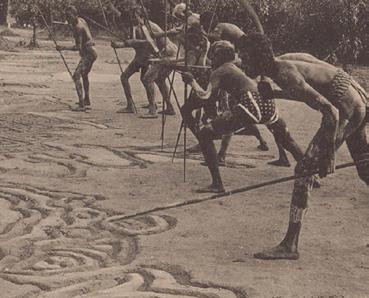
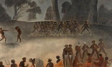
2. ‘Warriors in Ambush’, series 49, Aboriginal Mystic Bora Ceremony
3. Corroboree on the Murray River, 1858. Watercolour by Gerard Krefft.
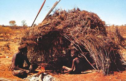
4. Daytime shade Photograph by R. Edwards in Isaacs, 1980
5. Village near Mt Shannon’ watercolour sketch by J. H. Le Keux in Sturt, 1849
6. Aboriginal family building bark shelter, Port Macquarie, 1905
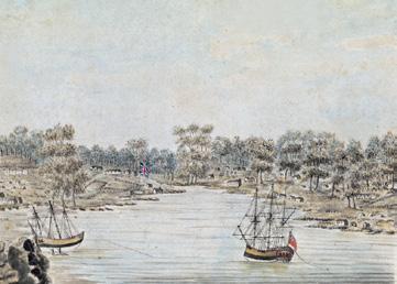
7. 1790, Local Aboriginal people in bark canoes on Sydney Harbour, depicted by the Port Jackoson painter
Design Concept
8. Aboriginal woman in a canoe fishing with a line
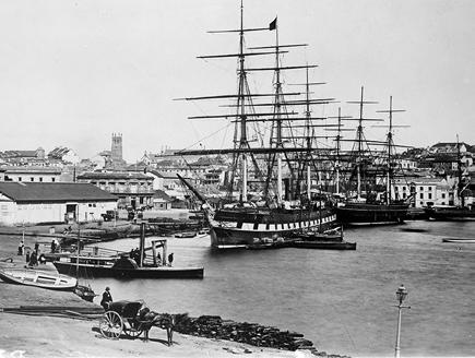
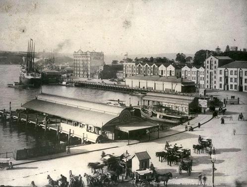
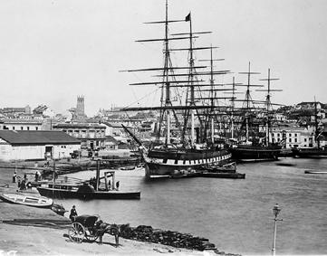
9. 1866 View of circular Quay
10. 1890 View of Circular Quay
11. 1788 Sydney Cove, Port Jackson, painting by William Bradley
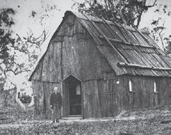
12. St Pauls Church of England, Stanthorpe, Queensland, originally built as a bark hut in 1872.
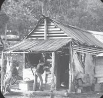
13. Bush store at Peats Ferry, Hawkesbury River,1887
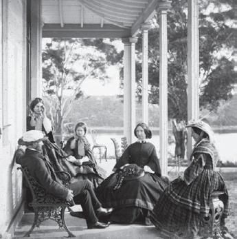
14. Group on verandah, Drummoyne Park

22
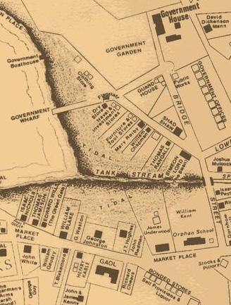
Sheltered Gathering Canopy - Protection & Shade Early Settler Building Silhouette Form - Derived from vernacular Aboriginal Shelter Roof - Fenestration & Transparency Structure - Ship Masts & Rigging Final Form Historic Harbour Context Lendlease Circular Quay | Plaza Building, George Street Public Artwork and Plaza| Architectural and Urban Design Report | Development Application November 2019 Adjaye Associates 18 1, ‘Members of a Family of Arunta [Natives], showing the Wurley, Weapons and Implements used in daily life’ original photograph, Baldwin Spencer, Central Australia 2, Aboriginal dugout, Tinnenburra Station, Queensland, 1910 3, Eucalypt dome shaped shelter, 1890s 4, Daytime shade Photograph by R. Edwards in Isaacs, 1980 5, ‘Village near Mt Shannon’ watercolour sketch by J. H. Le Keux in Sturt, 1849 6, Aboriginal family building bark shelter, Port Macquarie, 1905 1 6 Traditional Indigenous architecture was domestic, and varied from temporary windbreaks and wiltjas (shelters) of stringybark or paperbark to substantial round houses thatched with grass for large families. The materials of construction varied across geographic regions depending on the availability and supply of materials. These included stone, tree limbs for shelter frames and spinifex for cladding as well as in some regions mud & grass to waterproofing dome shelters. The construction methods varied from dome frameworks made of cane through spinifex-clad arc-shaped structures, to tripod and triangular shelters, and to elongated, egg-shaped, stone-based structures with a timber frame, and pole and platform constructions. Annual base camp structures, were designed for use over many years by the same family groups. Structures provided shelter and shade from the weather. The layout of individual shelters in campsites had to account for kinship and behaviour patterns between group members. Inspiration: Indigenous Gathering Corroboree is a generic word used to explain different genres of performance and cultural gathering by indigenous Australians. Throughout Australia the word corroboree embraces songs, dances, rallies and meetings of various kinds. Indigenous communities keep their cultural heritage alive by passing their knowledge, arts, rituals and performances from one generation to another, speaking and teaching languages, protecting cultural materials, sacred and significant sites, and objects. 3, ‘Warriors in Ambush’, series 49, Aboriginal Mystic Bora Ceremony 11 Inspiration: Indigenous Gathering 4 Corroboree is a generic word used to explain different genres of performance and cultural gathering by indigenous Australians. Throughout Australia the word corroboree embraces songs, dances, rallies and meetings of various kinds. Indigenous communities keep their cultural heritage alive by passing their knowledge, arts, rituals and performances from one generation to another, speaking and teaching languages, protecting cultural materials, sacred and significant sites, and objects. 2, Corroboree, William Barak, Wurundjeri artist, 1895 3, ‘Warriors in Ambush’, series 49, Aboriginal Mystic Bora Ceremony 4, Corroboree 185, William Blandowski 5, Corroboree on the Murray River, 1858. Watercolour by Gerard Krefft. 6, Aboriginal symbol for group sitting together 11 Gathering Corroboree is a generic word used to explain different genres of performance and cultural gathering by indigenous Australians. Throughout Australia the word corroboree embraces songs, dances, rallies and meetings of various kinds. Indigenous communities keep their cultural heritage alive by passing their knowledge, arts, rituals and performances from one generation to another, speaking and teaching languages, protecting cultural materials, sacred and artist, 1895 Mystic Bora Ceremony Watercolour by Gerard Krefft. Site History: Early Sydney settlement 1, 1788, Port Jackson and Sydney Cove Map 2, 1800, Map of Sydney 3, 1890 View of Circular Quay 4, 1866 View of circular Quay 5 1788 Sydney Cove, Port Jackson, painting by William Bradley 3 5 4 2 Expressway and Circular Quay railway in the 1950s. 9 1, 1788, Port Jackson and Sydney Cove Map 2, 1800, Map of Sydney 3, 1890 View of Circular Quay 4, 1866 View of circular Quay 5 1788 Sydney Cove, Port Jackson, painting by William Bradley 1 3 5 4 2 9 1, 1788, Port Jackson and Sydney Cove Map 2, 1800, Map of Sydney 3, 1890 View of Circular Quay 4, 1866 View of circular Quay 5 1788 Sydney Cove, Port Jackson, painting by William Bradley 1 3 5 4 2 10 Site
1, Aboriginal 2, Detail 3, Aboriginal Ceremony 4, Painting Governor 5, View of 6, Fish hook 7, 1790, Local Harbour, depicted
Design Concept
History: Eora & Cadigal
many as 29 clan groups
is believed that as
made up the Eora peoples.
area called “Cadi” that lies just south of Port Jackson and what is today Sydney’s central business district.
6 10
1, Aboriginal 2, Detail 3, Aboriginal Ceremony 4, Painting Governor 5, View 6, Fish hook 7, 1790, Harbour,
clan
Jackson
6
1, Banyan Homestead, Tully 2, ‘Evening’, Russell Drysdale, 1945 3, Group on verandah, Drummoyne Park 4, St Pauls Church of England, Stanthorpe, Queensland, originally built as a bark hut in 1872. 5, Bush store at Peats Ferry, Hawkesbury River,1887 6, Slab Hut, Belle Vue Station, Glencoe, NSW c. 1898 1 3 5 6 2 4 The first European buildings in Sydney were a prefabricated house for the Governor and a Government Store to house the colony’s supplies. Building anything more substantial was made unnecessarily difficult by the poor quality of spades and axes that had been provided and the shortage of nails. Settlers adapted simple building techniques commonly used for animal shelters and the locally available materials to create huts with wattle-and-daub. So useful were the local acacia trees for weaving shelters that they were given the name Wattle. The first imported roofing material was corrugated iron sheeting, however imported roofing was in short supply. The two local roofing materials available were reed beds for thatching or bark which could be peeled off a number of the indigenous trees. Methods of heating and flattening the bark were used by the Aboriginal people and these were quickly assimilated by Europeans. Typical houses were generally symmetrical, and very simple, usually containing 2 to 4 rooms around a central hallway. The simplest houses were a single room, also rectangular in form and with a pitched roof.
Inspiration: Early Settlers Structures
Inspiration: Indigenous Structures
Inspiration: Early Settlers Structures
Inspiration: Indigenous Gathering
Site History: Eora & Cadigal people
Inspiration: Early Sydney Settlements
Canopy - Protection & Shade Early Settler Building Silhouette Form - Derived from vernacular Aboriginal Shelter Roof - Fenestration & Transparency Structure - Ship Masts & Rigging Public Art Final Form Historic Harbour Context Lendlease Circular Quay | Plaza Building, George Street Public Artwork and Plaza| Architectural and Urban Design Report | Development Application November 2019 Adjaye Associates 18 1 2 3 4 5 6 7 8 9 10 11 12 13 14
Sheltered Gathering
With 3.6m
Adjacent to the tenacy space, a 24 hour accessible lobby allows users to access separate upper floors, cycle facilities and amenities and retail units below. A stair provides access to the upper
Adjacent to the tenacy space, a 24 hour accessible lobby allows users to access separate upper floors, cycle facilities and amenities and retail units below. A stair provides access to the upper levels.
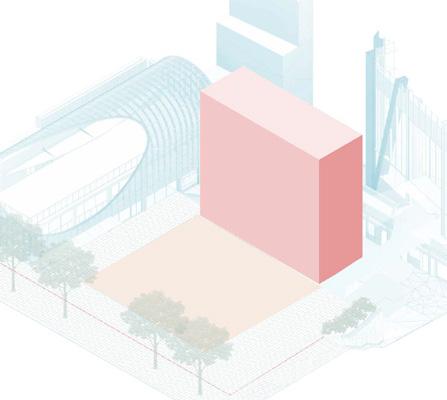
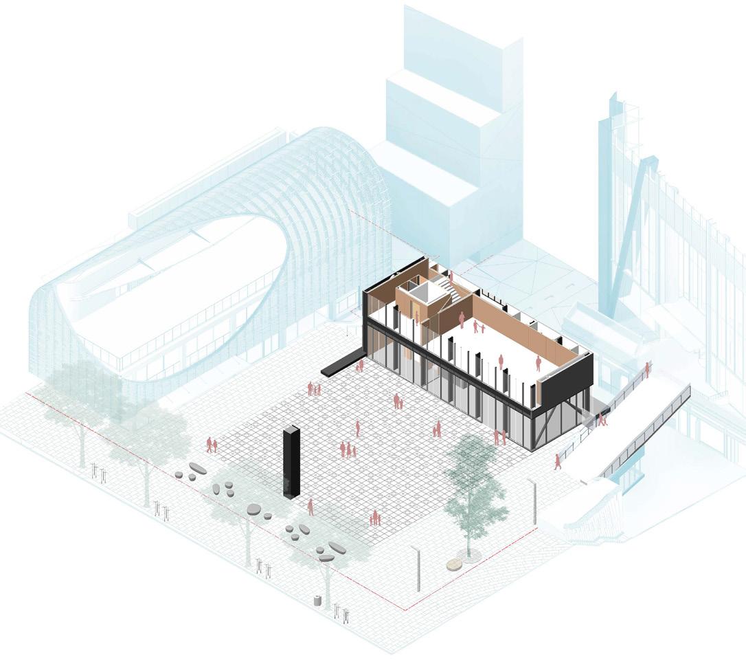
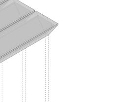
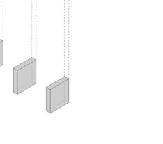
The building envelope consists of a 22.0m x 8.0m footprint that extends approximately 20.0m above the plaza level. Highlighted in red is the maximum height permitted by the brief, in yellow the proposed extended height of the overall envelope.
Level 1 has been designed as a flexible and multipurpose space that accommodates up to 50 people. It is connected to the other floors of the building via a lift and staircase.
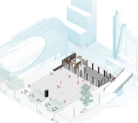
The configuration of the plaza allows for pedestrian connectivity with the rest of the LLCQ precinct. The ground floor of the Plaza Building has been designed with maximum permeability and transparency. The openable facade allows the floor plan to extend onto the plaza.
Plaza Building
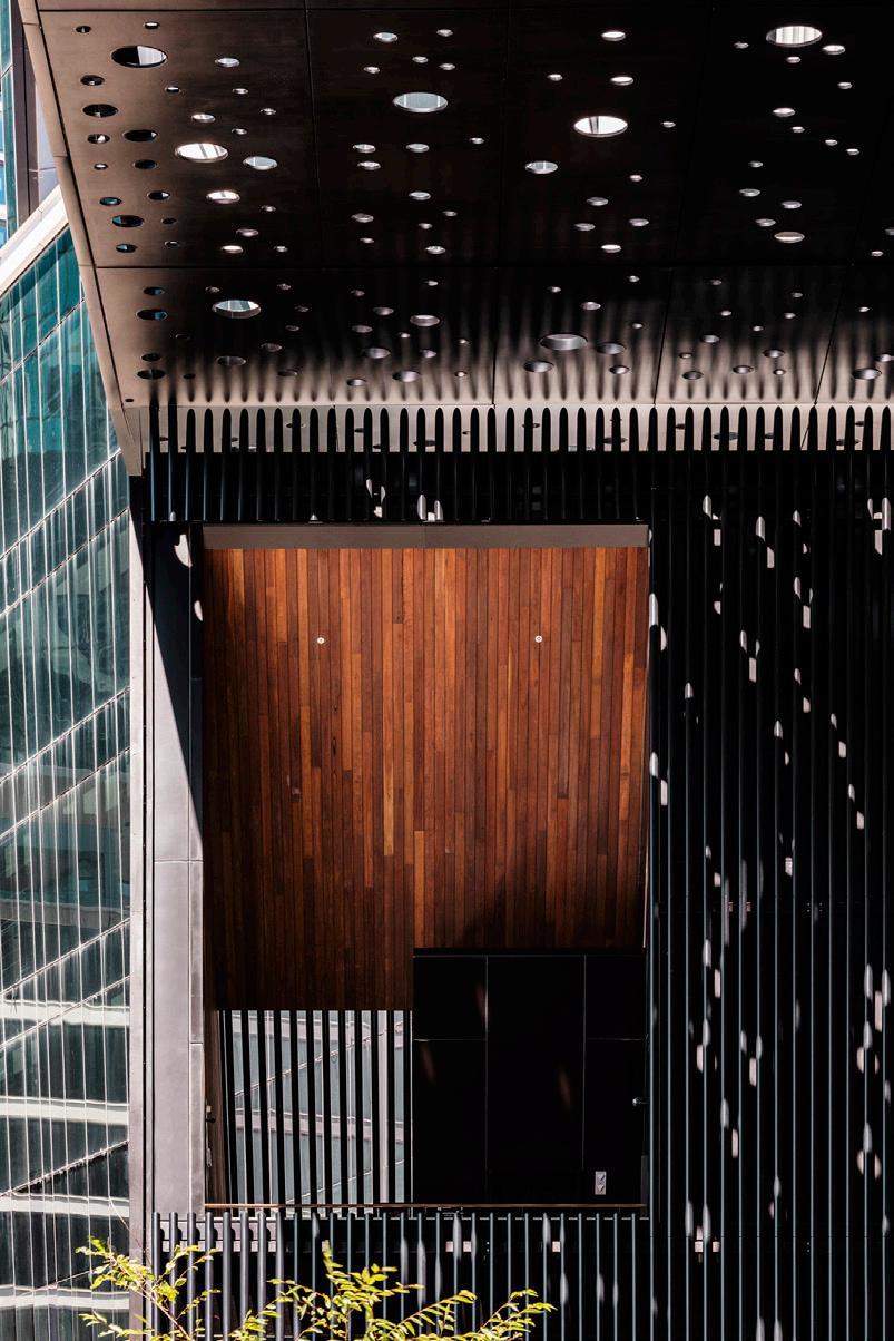
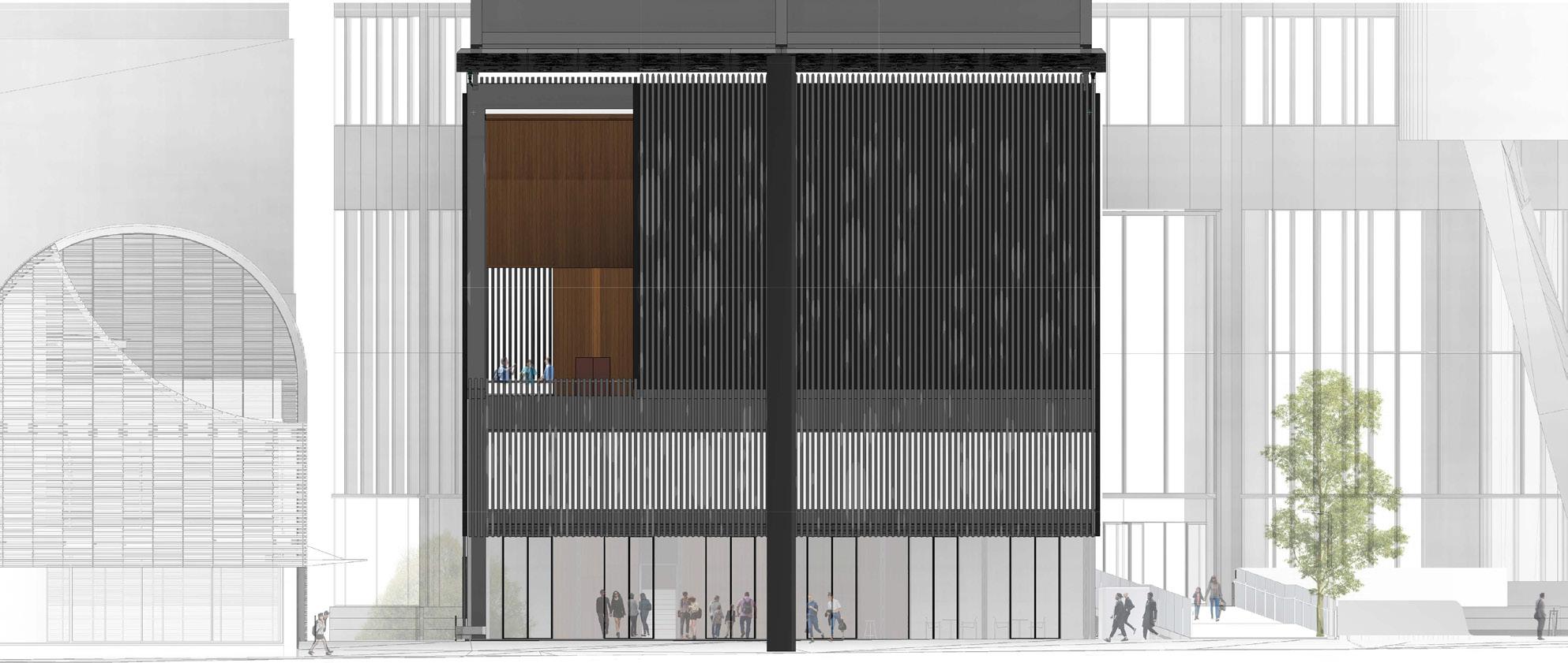
The full width glazed western façade faces onto the plaza and the height across both levels is screened by using the fenestration. The glazing has been designed to incorporate black-out blinds. Skylights are installed along the ridge line drawing in natural and filtered light from above.
The eastern wall cavity accommodates storage and reticulation of services. The floorplate configuration allows for a range of community uses.
The building has 2 levels with a mezzanine platform that provides views to the plaza. A tenancy space is situated at the Upper Ground Floor level, and a double height pitched ceiling multi-purpose space above. It accommodates a maximum of 50 people per floor.
Building | Building Overview
An external viewing platform has been integrated into the building to create a public area that overlooks George Street Plaza to the west and the laneways to the east.
It activates the front façade, offering a different vantage point for experiencing and viewing the large Canopy Artwork.
The materiality of the viewing platform, with its contrasting black metal fenestration and timber external elements, adds proportion and balance to the primary façade.
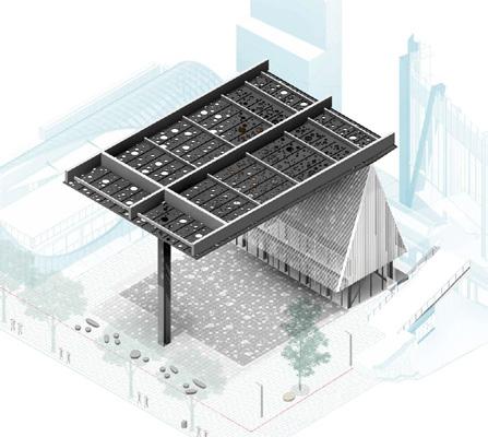
The canopy is designed in collaboration with Daniel Boyd. Inspired by Aboriginal dot painting, it articulates a cosmic journey and narrative of light that filters and refracts through multiple circular perforations, based on the oculi openings called Dawar’s (meaning star).
Serviced by the public lift, it connects visitors from the lower level at Crane Lane, enabling accessibility for all and reinforcing the building as a community hub for the city.
Space - Black-box mode and workshops-mode (internal image, as indicative only)
23 Lendlease Circular Quay | Plaza Building, George Street Public Artwork and Plaza| Architectural and Urban Design Report | 50% Developed Design Brief December 2019 Building Envelope Plaza Building George Street Plaza Canopy Artwork Located along the Western edge of George Street Plaza, the building envelope consists of a 22.0m x 8.0m footprint that extends approximately 20.0m above the plaza level. The Upper Ground Floor level is set to RL 7.150 and George Street Plaza provides an open space that connects and activates the surrounding buildings and the community, designed with the adaptability to change over time. The configuration of the plaza allows for pedestrian connectivity with the rest of the LLCQ precinct. ground floor of the Plaza Building has been designed with maximum permeability and transparency. A fully operable floor to ceiling façade allows the internal floor plan to extend out onto the plaza, creating a sense of The building is formed with 2 levels with a mezzanine viewing platform that provides views to the plaza and the laneways. A tenancy space is situated at the Upper Ground Floor level, and a double height pitched ceiling multipurpose space above at level 1. The public access lobby connects the building with the plaza and local environs below. Full height glazing is provided over the two floors along the West façade to engage with the plaza. It is also introduced on the South façade and portions of the East façade at Upper Ground Floor level. A circular window is incorporated into the North façade. The fenestration is used as a veil to provide privacy and shading to level 1. An external rear balcony is positioned to the East that overlooks Crane Lane. The rear balcony also creates separation between the two adjoining façade elements along Crane Lane and offers visual connectivity that overlooks the laneways and streetscape beneath. The building is designed to accommodate a maximum of 50 people per floor for the upper levels. The canopy structure above the plaza is designed by Adjaye Associates in collaboration with Daniel Boyd. Inspired by Aboriginal dot painting, the artwork articulates a cosmic journey and narrative of light that filters and refracts through multiple circular perforations, based on the oculi openings called Dawar’s (meaning star). The artwork is activated by natural light that permeates from above. It provides a shading element during the day and transforms into a recessed silhouette that is illuminated by surrounding lighting at night. Plaza Building DA Overview Design Overview Architectural and Urban Design Report | 50% Developed Design Brief December 2019 8 7 9 4 1 3 10 2 Lendlease Circular Quay | Plaza Building, George Street Public Artwork and Plaza| Architectural and Urban Design Report | 50% Developed Design Brief . December 2019 Adjaye Associates
fit-out
a separate application.
glass
facing the plaza, it
ideally
to provide a highly dynamic functional space
future tenants.
the
subject to
With 3.6m clear ceiling heights and full height operable
doors
is
placed
for
rear balcony extends the plaza from George Street to Crane Lane and activates the East façade. 1 Stair and Lift Lobby 2 Lift 3 Plant and Storage Room 4 Tenancy Space 5 George Street Plaza Stair and Lift Lobby (Image as indicative only) 6 Link Bridge 7 LLCQ Tower 8 Jacksons on George 9 Plaza Stair 10 PCF/ EOT Services Riser Lendlease Circular Quay | Plaza Building, George Street Public Artwork and Plaza| Architectural and Urban Design Report | 50% Developed Design Brief . December 2019 The
fit-out subject to a separate application.
levels. The
ground floor tenancy will be a warm shell with the
clear ceiling heights
facing the plaza,
highly dynamic
future tenants.
and full height operable glass doors
it is ideally placed to provide a
functional space for
extends the plaza from George Street to Crane Lane and activates the East façade. 8 9 Stair and Lift Lobby (Image as indicative only) Jacksons on George PCF/ EOT Services Riser Level UGF (Upper Ground Floor) Lendlease Circular Quay | Plaza Building, George Street Public Artwork and Plaza| Architectural and Urban Design Report | 50% Developed Design Brief . December 2019 Adjaye Associates
The rear balcony
Services
Storage Room Multipurpose Space Multipurpose
Plaza Building | Building Overview Lendlease Circular Quay | Plaza Building, George Street Public Artwork and Plaza| Architectural and Urban Design Report | 50% Developed Design Brief . December 2019 Adjaye
Stair and Lift Lobby
and
Associates
Plaza
Level
Architectural and Urban Design Report | 50% Developed Design Brief December 2019 4 1 3 2 Architectural and Urban Design Report | 50% Developed Design Brief December 2019 22 Level 2 Diagram N 4 3 1 2 Building
Viewing Platform (image as indicative only)
02
Envelope
George Street Plaza
Canopy
Artwork
Lendlease Circular Quay | Plaza Building, George Street Public Artwork and Plaza| Architectural and Urban Design Report | 50% Developed Design Brief December 2019 Adjaye Associates 5 E Building Envelope Plaza Building George Street Plaza Canopy Artwork Located along the Western edge of George Street Plaza, the building envelope consists of a 22.0m x 8.0m footprint that extends approximately 20.0m above the plaza level. The Upper Ground Floor level is set to RL 7.150 and the top of the building volume is set to RL 27.000. While the building envelope extends beyond the original datum (RL 24.000) prescribed in the design brief, its scale is considered appropriate for the surrounding context, including the commercial tower. Original volume datum. Top of the building: RL 24.000 Additional volume extent. Top of the building: RL 27.000 George Street Plaza provides an open space that connects and activates the surrounding buildings and the community, designed with the adaptability to change over time. The configuration of the plaza allows for pedestrian connectivity with the rest of the LLCQ precinct. The plaza provides zones for fixed, bespoke seating elements as well as temporary plaza seating. The ground floor of the Plaza Building has been designed with maximum permeability and transparency. A fully operable floor to ceiling façade allows the internal floor plan to extend out onto the plaza, creating a sense of openness and a visual connection to the plaza. The building is formed with 2 levels with a mezzanine viewing platform that provides views to the plaza and the laneways. A tenancy space is situated at the Upper Ground Floor level, and a double height pitched ceiling multipurpose space above at level 1. The public access lobby connects the building with the plaza and local environs below. Full height glazing is provided over the two floors along the West façade to engage with the plaza. It is also introduced on the South façade and portions of the East façade at Upper Ground Floor level. A circular window is incorporated into the North façade. The fenestration is used as a veil to provide privacy and shading to level 1. An external rear balcony is positioned to the East that overlooks Crane Lane. The rear balcony also creates separation between the two adjoining façade elements along Crane Lane and offers visual connectivity that overlooks the laneways and streetscape beneath. The building is designed to accommodate a maximum of 50 people per floor for the upper levels. The canopy structure above the plaza is designed by Adjaye Associates in collaboration with Daniel Boyd. Inspired by Aboriginal dot painting, the artwork articulates a cosmic journey and narrative of light that filters and refracts through multiple circular perforations, based on the oculi openings called Dawar’s (meaning star). The artwork is activated by natural light that permeates from above. It provides a shading element during day and transforms into a recessed silhouette that is illuminated by surrounding lighting at night. The artwork marks a clear identity within the city’s network as a place for social and cultural gathering. As a shaded space concentrated in the heart of the city, it functions as a key destination that can be enjoyed year round. Plaza Building DA Overview Design Overview Lendlease Circular Quay | Plaza Building, George Street Public Artwork and Plaza| Architectural and Urban Design Report | 50% Developed Design Brief . December 2019 Adjaye Associates 5 E Building Envelope Plaza Building George Street Plaza Canopy Artwork Located along the Western edge of George Street Plaza, the building envelope consists of a 22.0m x 8.0m footprint that extends approximately 20.0m above the plaza level. The Upper Ground Floor level is set to RL 7.150 and the top of the building volume is set to RL 27.000. While the building envelope extends beyond the original datum (RL 24.000) prescribed in the design brief, its scale is considered appropriate for the surrounding context, including the commercial tower. Original volume datum. Top of the building: RL 24.000 Additional volume extent. Top of the building: RL 27.000 George Street Plaza provides an open space that connects and activates the surrounding buildings and the community, designed with the adaptability to change over time. The configuration of the plaza allows for pedestrian connectivity with the rest of the LLCQ precinct. The plaza provides zones for fixed, bespoke seating elements as well as temporary plaza seating. The ground floor of the Plaza Building has been designed with maximum permeability and transparency. A fully operable floor to ceiling façade allows the internal floor plan to extend out onto the plaza, creating a sense of openness and a visual connection to the plaza. The building is formed with 2 levels with a mezzanine viewing platform that provides views to the plaza and the laneways. A tenancy space is situated at the Upper Ground Floor level, and a double height pitched ceiling multipurpose space above at level 1. The public access lobby connects the building with the plaza and local environs below. Full height glazing is provided over the two floors along the West façade to engage with the plaza. It is also introduced on the South façade and portions of the East façade at Upper Ground Floor level. A circular window is incorporated into the North façade. The fenestration is used a veil to provide privacy and shading to level 1. An external rear balcony is positioned to the East that overlooks Crane Lane. The rear balcony also creates separation between the two adjoining façade elements along Crane Lane and offers visual connectivity that overlooks the laneways and streetscape beneath. The building is designed to accommodate a maximum of 50 people per floor for the upper levels. The canopy structure above the plaza is designed by Adjaye Associates in collaboration with Daniel Boyd. Inspired by Aboriginal dot painting, the artwork articulates a cosmic journey and narrative of light that filters and through multiple circular perforations, based on the oculi openings called Dawar’s (meaning star). The artwork is activated by natural light that permeates from above. It provides a shading element during the day and transforms into a recessed silhouette that is illuminated by surrounding lighting at night. The artwork marks a clear identity within the city’s network as a place for social and cultural gathering. As a shaded space concentrated in the heart of the city, it functions as a key destination that can be enjoyed year round. Plaza Building DA Overview Design Overview Lendlease Circular Quay | Plaza Building, George Street Public Artwork and Plaza| Architectural and Urban Design Report | 50% Developed Design Brief . December 2019 Adjaye Associates 5 E Building Envelope Plaza Building George Street Plaza Canopy Artwork Located along the Western edge of George Street Plaza, the building envelope consists of a 22.0m x 8.0m footprint that extends approximately 20.0m above the plaza level. The Upper Ground Floor level is set to RL 7.150 and the top of the building volume is set to RL 27.000. While the building envelope extends beyond the original datum (RL 24.000) prescribed in the design brief, its scale is considered appropriate for the surrounding context, including the commercial tower. Original volume datum. Top of the building: RL 24.000 Additional volume extent. Top of the building: RL 27.000 George Street Plaza provides an open space that connects and activates the surrounding buildings and the community, designed with the adaptability to change over time. The configuration of the plaza allows for pedestrian connectivity with the rest of the LLCQ precinct. The plaza provides zones for fixed, bespoke seating elements as well as temporary plaza seating. The ground floor of the Plaza Building has been designed with maximum permeability and transparency. A fully operable floor to ceiling façade allows the internal floor plan to extend out onto the plaza, creating a sense of openness and a visual connection to the plaza. The building is formed with 2 levels with a mezzanine viewing platform that provides views to the plaza and the laneways. A tenancy space is situated at the Upper Ground Floor level, and a double height pitched ceiling multipurpose space above at level 1. The public access lobby connects the building with the plaza and local environs below. Full height glazing is provided over the two floors along the West façade to engage with the plaza. It is also introduced on the South façade and portions of the East façade at Upper Ground Floor level. A circular window is incorporated into the North façade. The fenestration is used as a veil to provide privacy and shading to level 1. An external rear balcony is positioned to the East that overlooks Crane Lane. The rear balcony also creates separation between the two adjoining façade elements along Crane Lane and offers visual connectivity that overlooks the laneways and streetscape beneath. The building is designed to accommodate a maximum of 50 people per floor for the upper levels. The canopy structure above the plaza is designed by Adjaye Associates in collaboration with Daniel Boyd. Inspired by Aboriginal dot painting, the artwork articulates a cosmic journey and narrative of light that filters and refracts through multiple circular perforations, based on the oculi openings called Dawar’s (meaning star). The artwork is activated by natural light that permeates from above. It provides a shading element during the day and transforms into a recessed silhouette that is illuminated by surrounding lighting at night. The artwork marks a clear identity within the city’s network as a place for social and cultural gathering. As a shaded space concentrated in the heart of the city, it functions as a key destination that can be enjoyed year round. ~20 m 8m 22m Plaza Building DA Overview Design Overview
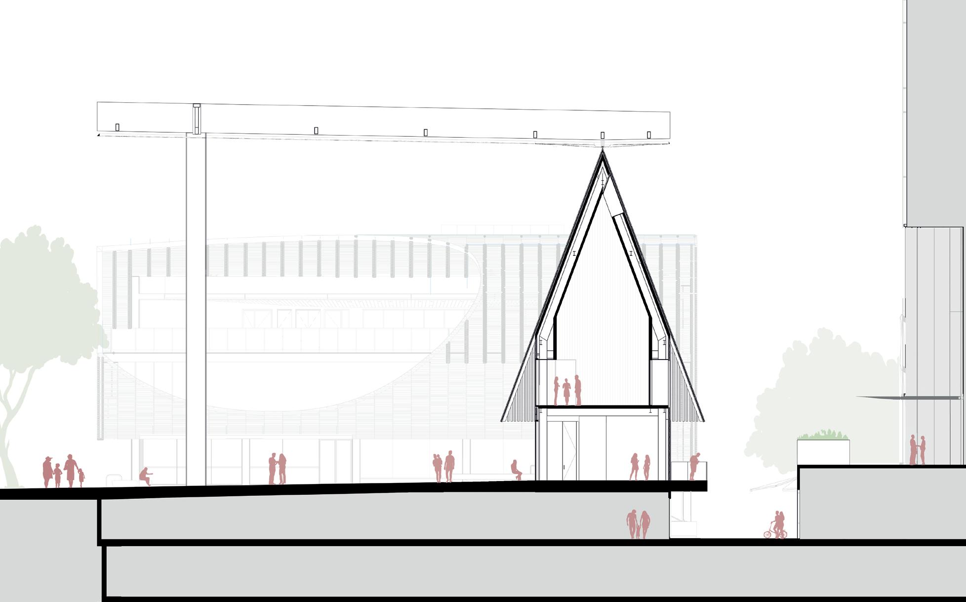
24 Upper Ground Floor TENANCY SPACE BALCONY LOBBY SERVICES RISER STORAGE STAIR Level 01 MULTI-PURPOSE SPACE LOBBY STORAGE EL COMMS STAIR STORAGE STORAGE STORAGE STORAGE STORAGE SINK CBD SHARED SERVICES RISER Level 02 OPEN TO BELOW STAIR Lendlease Circular Quay | Plaza Building, George Street Public Artwork and Plaza| Architectural and Urban Design Report | Development Application November 2019 Adjaye Associates 41 Plaza Building LLCQ Site Boundary George Street George Street Plaza 1:60 Crane Lane LLCQ Tower +7.150 +11.700 +14.850 +27.000 +29.680 +3.800 Upper Ground Level Level 01 Level 02 U/S Canopy T/O Truss Lower Ground Level Jacksons on George Multi-purpose Space Tenancy Cafe Roof Fenestration 2060mm 3600mm 6950mm 3600mm 2700mm 2500mm 9880mm Roof Fenestration 2060mm Primary Building Envelope 8000mm Canopy above Public Plaza 24085mm Canopy above Crane Lane 6015mm Column Setback 5925mm 70 Cross Section 10m 5 0 Lendlease Circular Quay | Plaza Building, George Street Public Artwork and Plaza| Architectural and Urban Design Report | Development Application . November 2019 Adjaye Associates 41 Plaza Building LLCQ Site Boundary George Street George Street Plaza 1:60 Crane Lane LLCQ Tower +7.150 +11.700 +14.850 +27.000 +29.680 +3.800 Upper Ground Level Level 01 Level 02 U/S Canopy T/O Truss Lower Ground Level Jacksons on George Multi-purpose Space Tenancy Cafe Roof Fenestration 2060mm 3600mm 6950mm 3600mm 2700mm 2500mm 9880mm Roof Fenestration 2060mm Primary Building Envelope 8000mm Canopy above Public Plaza 24085mm Canopy above Crane Lane 6015mm Column Setback 5925mm 70 Cross Section 10m 5 0 Ground Level 1 Level 2
25 F1 F4 F2 F5 F3 Black Granite Paving Timber Cladding Black Metal Cladding Glazing Lendlease Circular Quay | Plaza Building, George Street Public Artwork and Plaza| Architectural and Urban Design Report | 50% Developed Design Brief December 2019 Adjaye Associates 7 10m 5 0 Plaza Building DA Overview North Elevation F5 F5 F5 F4 F4 F3 F3 F5 F1 F4 F2 F5 F3 Black Granite Paving Black Metal Fenestration Tubes Timber Cladding Black Metal Cladding Glazing Lendlease Circular Quay | Plaza Building, George Street Public Artwork and Plaza| Architectural and Urban Design Report | 50% Developed Design Brief . December 2019 Adjaye Associates 7 10m 5 0 Plaza Building | DA Overview North Elevation F5 F1 F1 F4 F3 F3 F5 F1 F4 F2 F5 F3 Black Granite Paving Black Metal Fenestration Tubes Timber Cladding Black Metal Cladding Glazing Lendlease Circular Quay | Plaza Building, George Street Public Artwork and Plaza| Architectural and Urban Design Report | 50% Developed Design Brief December 2019 Adjaye Associates 10 10m 5 0 Plaza Building DA Overview West Elevation F5 F1 F1 F4 F3 F3 F5 F1 F4 F2 F5 F3 Black Granite Paving Black Metal Fenestration Tubes Timber Cladding Black Metal Cladding Glazing Lendlease Circular Quay | Plaza Building, George Street Public Artwork and Plaza| Architectural and Urban Design Report | 50% Developed Design Brief December 2019 Adjaye Associates 10 10m 5 0 Plaza Building DA Overview West Elevation F5 F1 F1 F4 F3 F3 F5 F1 F4 F2 F5 F3 Black Granite Paving Black Metal Fenestration Tubes Timber Cladding Black Metal Cladding Glazing Lendlease Circular Quay | Plaza Building, George Street Public Artwork and Plaza| Architectural and Urban Design Report | 50% Developed Design Brief . December 2019 Adjaye Associates 10 10m 5 0 Plaza Building | DA Overview West Elevation
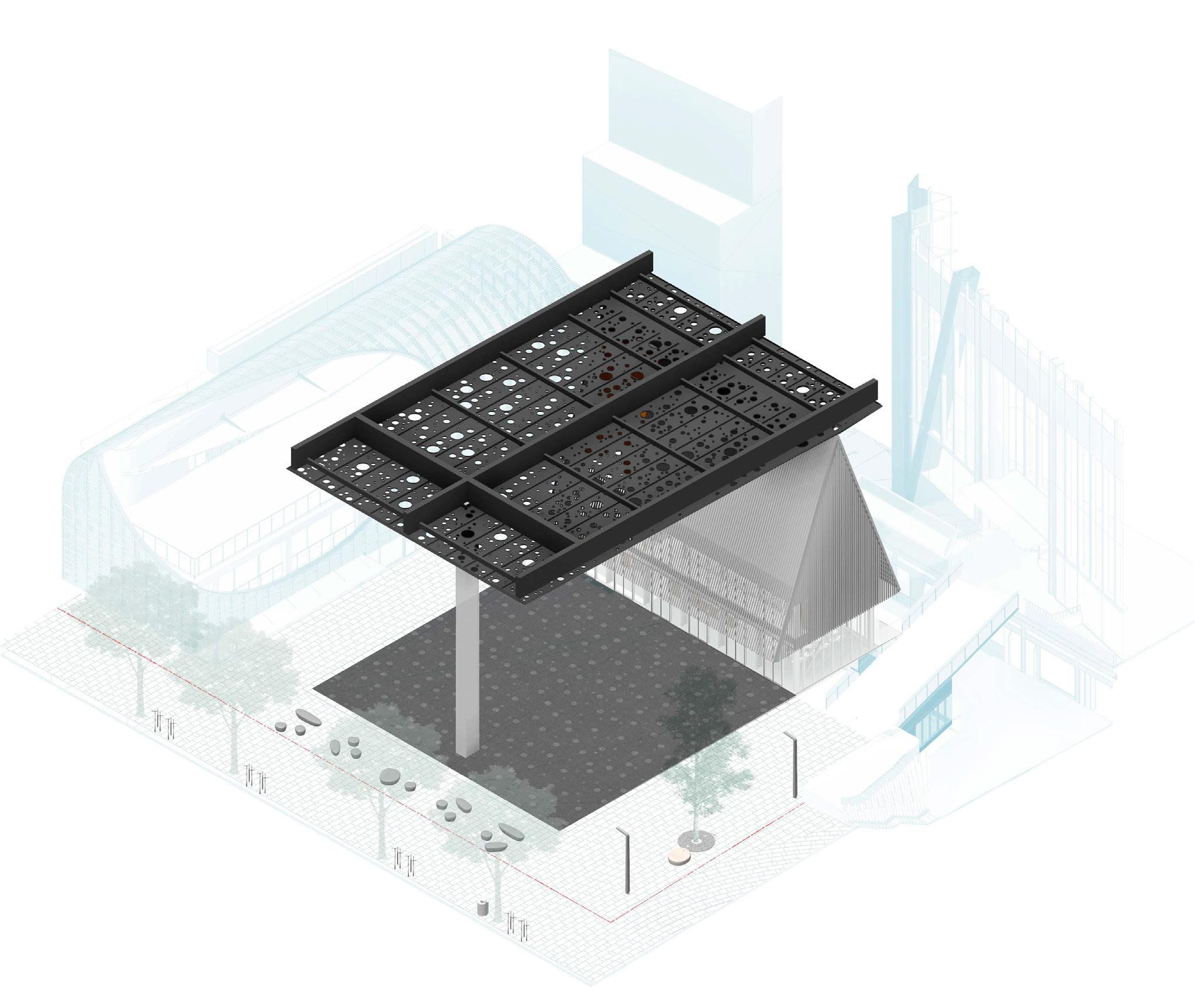
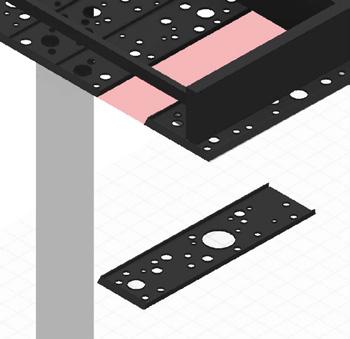
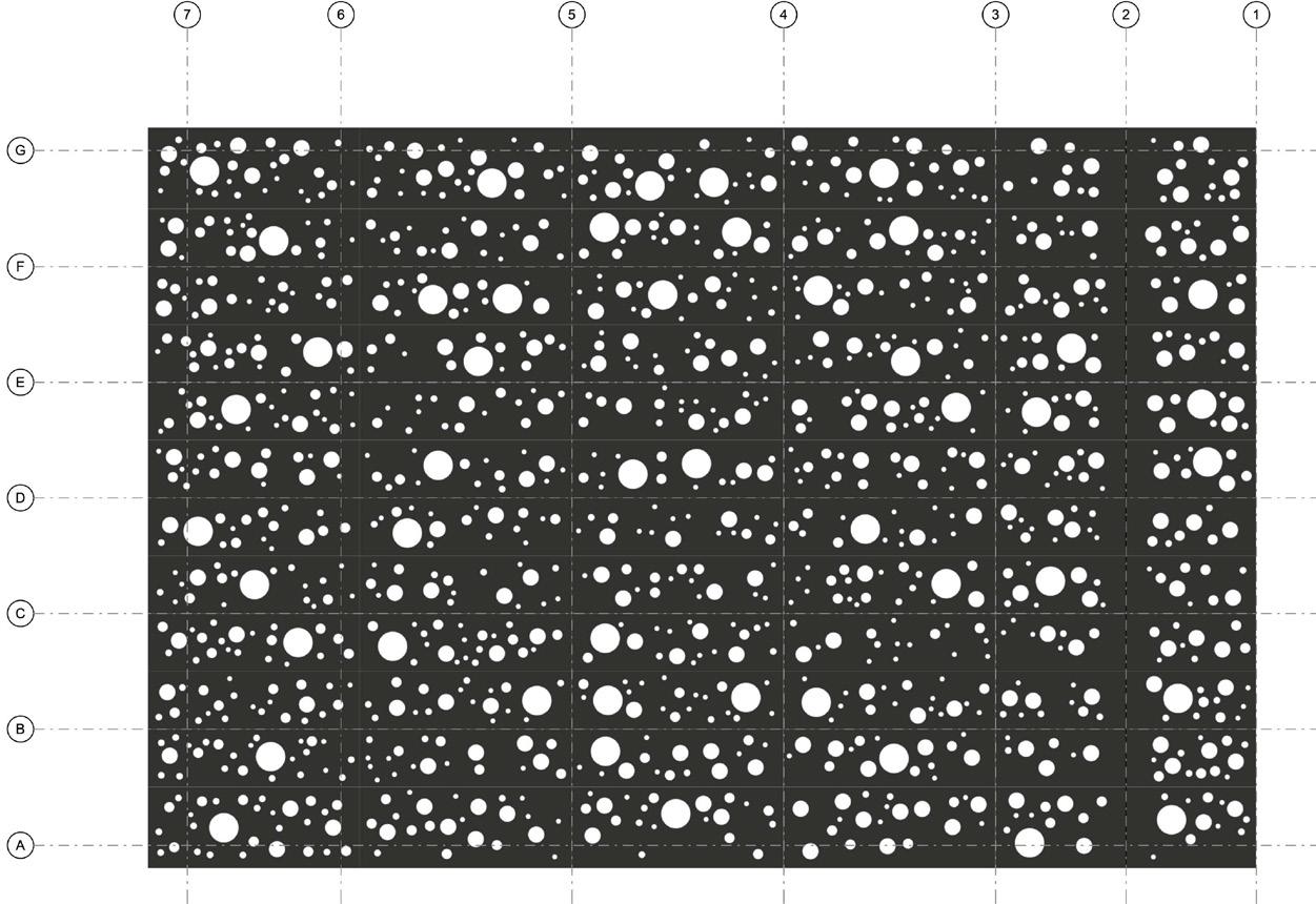
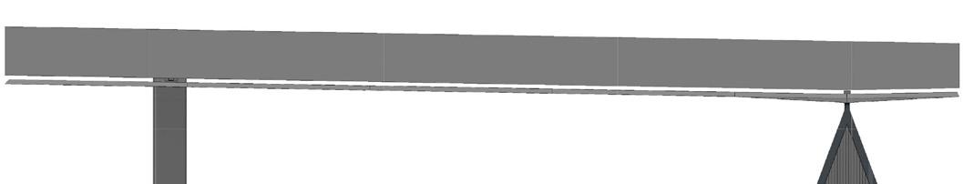
26 Lendlease Circular Quay | Plaza Building, George Street Public Artwork and Plaza| Architectural and Urban Design Report | 50% Developed Design Brief December 2019 Adjaye Associates 15 Plaza Building DA Overview Artwork Canopy R.L. 27.000 Canopy South Elevation (Image shown indicatively) 3550 1775 1200 700 700 3570 3550 3550 22740 34000 3550 3550 3570 4715 7085 6500 6500 4000 Box Gutter Draingage Zone 4000 Underside of Canopy Plan The Canopy Artwork is a steel framed structure that covers the new public plaza. The primary support trusses and secondary structure suspend the canopy from above. It consists of a grid of metal panels, assembled together to form a monolithic artwork. The modular panels are specifically designed and prefabricated to be rapidly installed on site. This also takes quality control and ease of transportation into consideration. The dimensions, position of openings and final pattern design of the artwork canopy will be subject to design development and final sign off by the Artist Daniel Boyd. Panels fixed to support steelwork and adjacent panels above Example of two panels joined together Lendlease Circular Quay | Plaza Building, George Street Public Artwork and Plaza| Architectural and Urban Design Report | 50% Developed Design Brief December 2019 Adjaye Associates 15 R.L. 27.000 Canopy South Elevation (Image shown indicatively) 3550 6500 1775 700 3550 3550 22740 34000 3550 3550 3570 Box Gutter Draingage Zone Underside of Canopy Plan takes quality control and ease of transportation into consideration. The dimensions, position of openings and final pattern design of the artwork canopy will be subject to design development and final sign off by the Artist Daniel Boyd. Panels fixed to support steelwork and adjacent panels above Example of two panels joined together Street Public Artwork and Plaza| Architectural and Urban Design Report | 50% Developed Design Brief . December 2019 12 stone' 1 multifunctional community canopy that provide shading artwork. The and promotes permanent and seating that can activates the Plaza, the of a major Street’s that the plaza maximum flexibility Furniture - CoS palet 17 Sheffield Bike racks 18 Rubbish Bin 19 Light pole Artwork and Plaza| Architectural and Urban Design Report | 50% Developed Design Brief . December 2019 12 11 9 2 3 4 14 5 10 12 16 15 19 1 18 17 7 6 8 13 community promotes plaza flexibility
27
28
29 1 2 3 Level 02 14850 FFL U/S Canopy 27000 FFL Level 01 11700 FFL 1 C_AD610291 TENANCY SPACE MULTI-PURPOSE SPACE GEORGE STREET PLAZA IWF-02 FT-02 4000 4000 8000 Cafe fit-out subject to separate approval 0 6 600 0 6 600 00 600 600 600 600 600 600 160 12 600 3459 600 600 600 600 600 600 00 600 6 160 4 600 600 1200 600 600 600 600 781 350 350 3500 705 781 86 6 1578 500 3500 470 DOUBLE GLAZED WINDOWS FRAME AND INTEGRATED BLACKOUT BLINDS; TO ENVELOPE CONSULTANT DESIGN AND SPECS STEEL STRUCTURE TO DESIGN AND SPECS. ALL STEEL COLUMNS, BE INTUMESCENT PAINT. TUBULAR ROOF PANELS. APROX. 9000MM LONG X 1800MM WIDE. MADE OF 100mm DIA. CHS STEEL TUBES AT 200MM CENTRES. TUBES TO BE SEALED,EXPOXY PAINTED WITH ARCHITECTURAL FINISH. ROOF CANOPY FIXING CLEAT TO STRUCTURAL ENGINEER DESIGN AND SPECS; FENESTRATION DRESSED TO SIDE OF CLEAT MINIMAL ALUMINIUM FRAME DOUBLE BLACKOUT BLINDS TO INHABIT SPECIFICATIONS; REFER TO 620000 150x50x4 RHS WELDED TO 'FENESTRATION' RODS WITH CLADDING; TO INHABIT SPECIFICATIONS CT06 TO SERVICES ENGINEER DESIGN AND SPECS; COLOUR TO MATCH BLACK METAL CLADDING 150x100x6 RHS LATERAL SUPPORT TO BLACK PAINTED FINISH TO MATCH BLACK METAL CLADDING; TO INHABIT SPECIFICATIONS 70° 70 C_AD620106 Sim BLACK PAINTED RAINSCREEN CLADDING FIXED TO 2mm GALVANIZED STEEL SHEET ON INSULATION BLANKET WITH REFLECTIVE FILM OVER -ANGLE EDGE TRIM WITH BLACK PAINTED FINISH TO MATCH BLACK METAL CLADDING; TO INHABIT SPECIFICATIONS C_AD610281 C_AD610291 C_AD610293 RF-01 LEGEND WP01 COLD FLUIDAPPLIED MEMBRANE WATERPROOFING WP02 WP03 WP04 2mm GALVANISED SHEET REFLECTIVE FOIL VAPOUR CONTROL LAYER EDPM BONDED TO GLAZING UNITS AND OVERLAPPED WITH WATERPROOFING INTERFACES WATERPROOFING SHEET VAPOUR CONTROL LAYER 1000 2000mm 200 Drawing No. Revision Drawing Title General Notes 1. Drawing to be read in conjunction with the specification and all relevant drawings. 2. Do not scale drawings. 3. All dimensions are in milimeters unless noted otherwise. 4. All dimensions shall be verified on site before proceeding with the work. 5. Adjaye Associates shall be notified in writing of any discrepancies. 6. All information provided by others shown of information only and remains the responsibility of the author. 7.This drawing maybe subject to change in relation to the above and pending approval from the City of Sydney. The Edison 223-231 Old Marylebone Road London NW1 5QT +44 (0)20 7258 6140 info@adjaye.com Adjaye Associates Principal Architect Project Description Lendlease Circular Quay Plaza Building and George Street Plaza 180 George Street Sydney NSW 2000 Plaza Jacksons on George Street Scale Date Collaborating Architect Client Developer Level 14 Tower Three, International Towers Sydney Barangaroo NSW 2000 18 MLC Centre 19 Martin Place Sydney NSW 2000 +61 8252 8400 +61 8252 8600 www.architectus.com.au Key Plan Checked By Drawn By As indicated @ B1 28/08/2020 C_AD610222 Facade SectionMultipurpose SpaceSkylight NH BK 1 20 CROSS SECTION -MULTIPURPOSE SPACE 1 This drawing is issued for information relating to the Building Envelope and Facade only. Information relating to adjoining elements such as floors, ceilings, doors, acoustic timber linings, access panels, louvres, waterproofing, envelope etc shown indicatively, pending further design development at the later workstages. Refer to C_AD630000 series for Roof and Fenestration Panel packages. For External Wall Finishes refer to Drawing C_AS000045External Wall Finish Types. For Internal Assemblies and Details refer to C_AD700000/ C_AD800000 packages. All structural elements MEP information are shown indicativelyto be designed and coordinated at later workstages. Building assemblies are shown indicatively and are subject change. RevisionDate Description 121/05/202090% DD VPA Submission 228/08/202050% CD VPA Submission ** BLOCKWORK UPSTANDS TO BE INSTALLED AND SEQUENCED PRIOR TO RAINSCREEN CLADDING Stage 4 Drawings Packages
30

31 F D 1 C_AD610224 GL-013550 3550 IN-SITU CONCRETE WALLS TO STRUCTURAL ENGINEERG DESIGN AND SPECIFICATIONS C_AD610221100mm DIA. CHS STEEL TUBES AT NOM. 200MM CENTRES. TUBES TO BE FULLY SEALED WITH -COAT PAINTED WITH ARCHITECTURAL FINISH TO INHABIT SPECIFICATIONS SHEETING; TO BE OVERLAPPED C_AD610293 D C B 1 7100 SINK CBD SERVICES RISER---WP01WP02 WP03 WP04 Drawing No. Drawing Title and pending approval from the City of Sydney. The Edison 223-231 Old Marylebone Road London NW1 5QT T +44 (0)20 7258 6140 info@adjaye.com Adjaye Associates Project Description Lendlease Circular Quay Plaza Building and George Street Plaza 180 George Street Sydney NSW 2000 Level 14 Tower Three, International Towers Sydney Barangaroo NSW 2000 18 MLC Centre 19 Martin Place Sydney NSW 2000 T +61 8252 8400 F +61 8252 8600 www.architectus.com.au Checked By Drawn By As indicated @ B1 28/08/2020 C_AD610215 Level 01 Setout - East Facade 20 LEVEL 01 -EAST WALL SETOUT PLAN 1 1 20 LEVEL 01 -EAST WALL SETOUT PLAN 2 This drawing is issued for information relating to the Building Envelope and Facade only. Information relating to adjoining elements such as floors, ceilings, doors, acoustic timber linings, access panels, louvres, waterproofing, envelope etc shown indicatively, pending further design development at the later workstages. Refer to C_AD630000 series for Roof and Fenestration Panel packages. For External Wall Finishes refer Drawing C_AS000045External Wall Finish Types. For Internal Assemblies and Details refer to C_AD700000/ C_AD800000 packages. indicatively - to be designed and coordinated at later workstages. Building assemblies are shown indicatively and are subject to change. RevisionDate Description F D 1 C_AD610224 GL-01IN-SITU CONCRETE WALLS TO STRUCTURAL ENGINEERG DESIGN AND SPECIFICATIONS C_AD610221100mm CHS STEEL TUBES AT NOM. 200MM CENTRES. TUBES TO BE FULLY SEALED WITH -COAT PAINTED WITH ARCHITECTURAL FINISH TO INHABIT SPECIFICATIONS SHEETING; TO BE OVERLAPPED C_AD610293 D C B 1 SINK CBD SERVICES RISER---WP01WP02 WP03 WP04 Drawing No. Drawing Title and pending approval from the City of Sydney. The Edison 223-231 Old Marylebone Road London NW1 5QT T +44 (0)20 6140 info@adjaye.com Adjaye Associates Project Description Lendlease Circular Quay Plaza Building and George Street Plaza 180 George Street Sydney 2000 Level 14 Tower Three, International Towers Sydney Barangaroo NSW 2000 18 MLC Centre 19 Martin Place Sydney NSW 2000 T +61 8400 F +61 8600 www.architectus.com.au Checked By Drawn By As indicated @ B1 28/08/2020 C_AD610215 Level 01 Setout - East Facade 1 20 LEVEL 01 -EAST WALL SETOUT PLAN 1 1 20 LEVEL 01 -EAST WALL SETOUT PLAN 2 This drawing issued for information relating to the Building Envelope and Facade only. Information relating to adjoining elements such as floors, ceilings, doors, acoustic timber linings, access panels, louvres, waterproofing, envelope etc shown indicatively, pending further design development at the later workstages. Refer to C_AD630000 series for Roof and Fenestration Panel packages. For External Wall Finishes refer to Drawing C_AS000045External Wall Finish Types. For Internal Assemblies and Details refer to C_AD700000/ C_AD800000 packages. indicatively - to be designed and coordinated at later workstages. Building assemblies are shown indicatively and are subject to change. RevisionDate Description Stage 4 Drawings Packages 2 3 U/S Canopy 27000 FFLSYPHONIC DRAINAGE BEHIND 8MM STEEL FIN PLATE 440 200 440 STRUCTURAL ENGINEER DESIGN AND SPECS ROOF ASSEMBLY (232mm DEPTH) 4mm BLACK ALUMINIUM CLADDING PANELS WITH CASSETTE PROFILE (50mm TOTAL DEPTH) 50mm VENTILATED AIR CAVITY 2mm GALVANISED STEEL SHEETING R3.6 INSULATION BLANKET (130mm) WITH REFLECTIVE FOIL BETWEEN 100mm Z-GIRTS WITH DESIGN AND SPECS. FIXING 400 ROOF PURLINS @ OPENING INDICATIVE ONLY - TO INHABIT SPECIFICATIONS - UNDER DESIGN REVIEW70 0 250 500mm 50 Drawing No. Drawing Title 4. All dimensions shall be verified on site before proceeding with 5. Adjaye Associates shall be notified in writing of any discrepancies. 6. All information provided by others shown of information only and remains the responsibility of the author. 7.This drawing maybe subject to change in relation to the above and pending approval from the City of Sydney. The Edison 223-231 Old Marylebone Road London NW1 5QT +44 (0)20 7258 6140 info@adjaye.com Adjaye Associates Lendlease Circular Quay Collaborating Architect Level 14 Tower Three, International Towers Sydney Barangaroo NSW 2000 19 Martin Place Sydney NSW 2000 +61 8252 8600 www.architectus.com.au Key Plan Checked By Drawn By 1 5 @ B1 C_AD630241 Artwork Canopy Details Description 121/05/202090% DD VPA Submission 228/08/202050% CD VPA Submission CANOPY ARTWORK -CANOPY ASSEMBLY AT BUILDING RIDGE 1 Any information on this drawing issued for design intent only. Location of public domain elements, feature stair location, and viewing platform to be confirmed by the City of Sydney. All structural elements MEP, lighting fixtures and fire services information are shown indicatively - to be designed and coordinated at later workstages. 2 3 U/S Canopy 27000 FFLSYPHONIC DRAINAGE BEHIND 8MM STEEL FIN PLATE 440 200 440 400 STRUCTURAL ENGINEER DESIGN AND SPECS ROOF ASSEMBLY (232mm DEPTH) 4mm BLACK ALUMINIUM CLADDING PANELS WITH CASSETTE PROFILE (50mm TOTAL DEPTH) 50mm VENTILATED AIR CAVITY 2mm GALVANISED STEEL SHEETING R3.6 INSULATION BLANKET (130mm) WITH REFLECTIVE FOIL BETWEEN 100mm -GIRTS WITH DESIGN AND SPECS. 0 FIXING ROOF PURLINS @ OPENING INDICATIVE ONLY - TO INHABIT SPECIFICATIONS - UNDER DESIGN REVIEW70 250 500mm 50 Drawing No. Drawing Title 4. All dimensions shall be verified on site before proceeding with 5. Adjaye Associates shall be notified in writing any discrepancies. 6. All information provided by others is shown of information only and remains the responsibility of the author. 7.This drawing maybe subject to change relation to the above and pending approval from the City of Sydney. The Edison 223-231 Old Marylebone Road London NW1 5QT +44 (0)20 7258 6140 info@adjaye.com Adjaye Associates Lendlease Circular Quay George Street Collaborating Architect Level 14 Tower Three, International Towers Sydney Barangaroo NSW 2000 19 Martin Place Sydney NSW 2000 +61 2 8252 8600 www.architectus.com.au Key Plan Checked By Drawn By 1 5 @ B1 C_AD630241 Artwork Canopy Details Description 121/05/202090% DD VPA Submission 228/08/202050% CD VPA Submission CANOPY ARTWORK -CANOPY ASSEMBLY AT BUILDING RIDGE 1 Any information on this drawing is issued for design intent only. Location public domain elements, feature stair location, and viewing platform to be confirmed by the City of Sydney. All structural elements MEP, lighting fixtures and fire services information shown indicatively - to be designed and coordinated at later workstages.
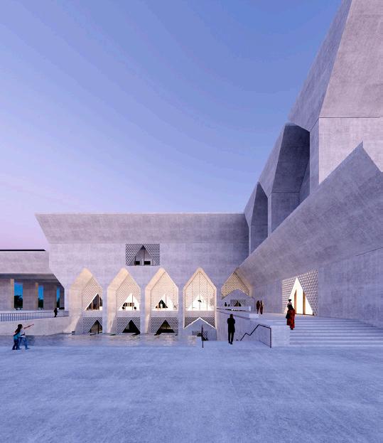
KIRAN NADAR CULTURAL CENTRE
100.000m2 Museum of Art/Cultural Centre
New Delhi, India
RIBA Stages 1- 6 (Under Construction)
2022
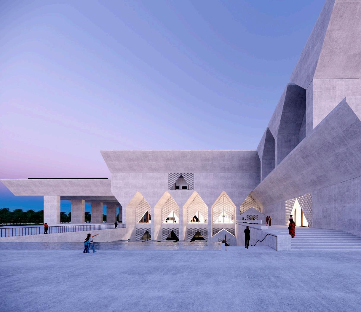
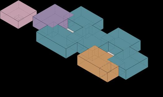
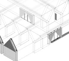
The Nadar Cultural Centre is a dynamic and modern space that aims to promote contemporary Indian art and culture. Located in Delhi, one of the world’s oldest cities, the center draws inspiration from its historical context to become a vibrant cultural force. The architectural design features a chequered arrangement of independent volumes with internal courtyards allowing natural light to enliven the campus.
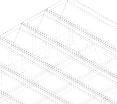
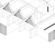
The proposal unfolds the center as a network of connected spaces, offering moments of reflection and introspection before immersing visitors in a world of art and ideas. The ground floor plan is organized into a grid of 8x8 meter squares, supplemented by various facilities such as galleries, exhibition spaces, auditoria, offices, and retail areas.
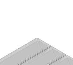
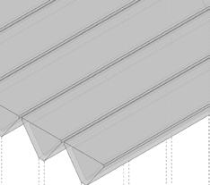
At the heart of the design lies a large span system of V-shaped beams, providing both structural support and a distinctive aesthetic. These beams, made of untreated white concrete, contribute to the building’s rational and modular form, eliminating the need for additional interior finishing, thus enhancing cost-effectiveness and sustainability.
32
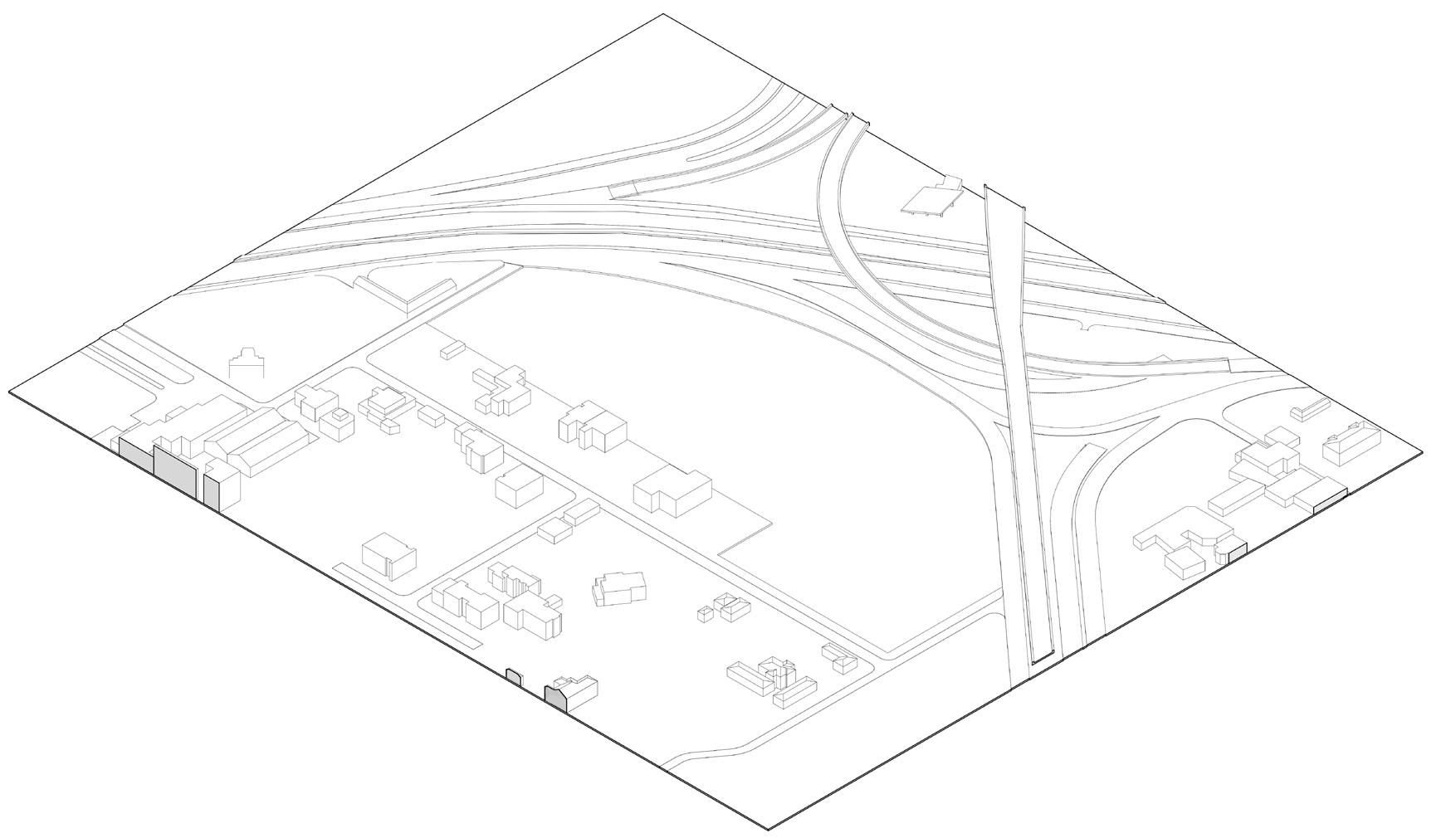
ProposedRoadExtension
33
Plot 5 Plot 6 NH8
Indira Gandhi Airport
Node
Scale Retail
SITE 3 Auditoria Foyer Galleries Office Research & Education
Proposed UER II Extension
Towards Delhi TowardsGurgaon Hospitality, Small
Warehouses & Storage Facility Farmhouses


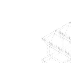
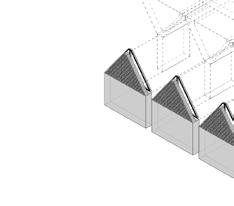


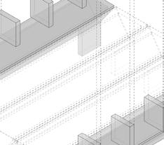
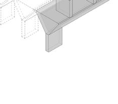

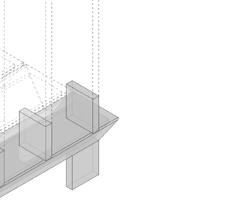
Columns and Beams
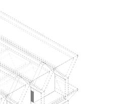

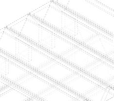
Walls, Punched Windows and Clerestory Windows
34 8m 31m 40m 40m 8m 8m 40m 40m GF
Side
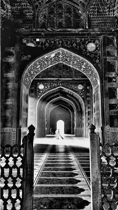
CULTURAL CONTEXT
Cultural Context
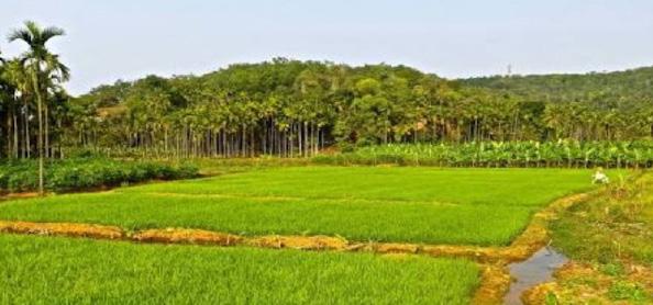
The Writer’s Eye - William Dalrymple Rice Fields, Uttar Pradesh
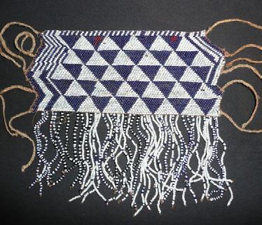
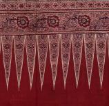
Detail Of Dyed Textile, Delhi Burnt Timber Harp, Rwanda
CULTURAL CONTEXT
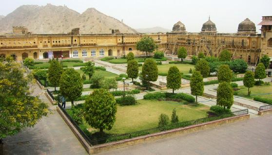
Tutsi Bead Ornament, Rwanda Aamer Fort Gardens, Jaipur
The Writer’s Eye - William Dalrymple Rice Fields, Uttar Pradesh
Detail Of Dyed Textile, Delhi Burnt Timber Harp, Rwanda
CULTURAL CONTEXT
Tutsi Bead Ornament, Rwanda Aamer Fort Gardens, Jaipur
The Writer’s Eye - William Dalrymple Rice Fields, Uttar Pradesh
Detail Of Dyed Textile, Delhi Burnt Timber Harp, Rwanda
Tutsi Bead Ornament, Rwanda Aamer Fort Gardens, Jaipur
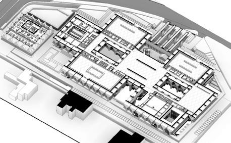
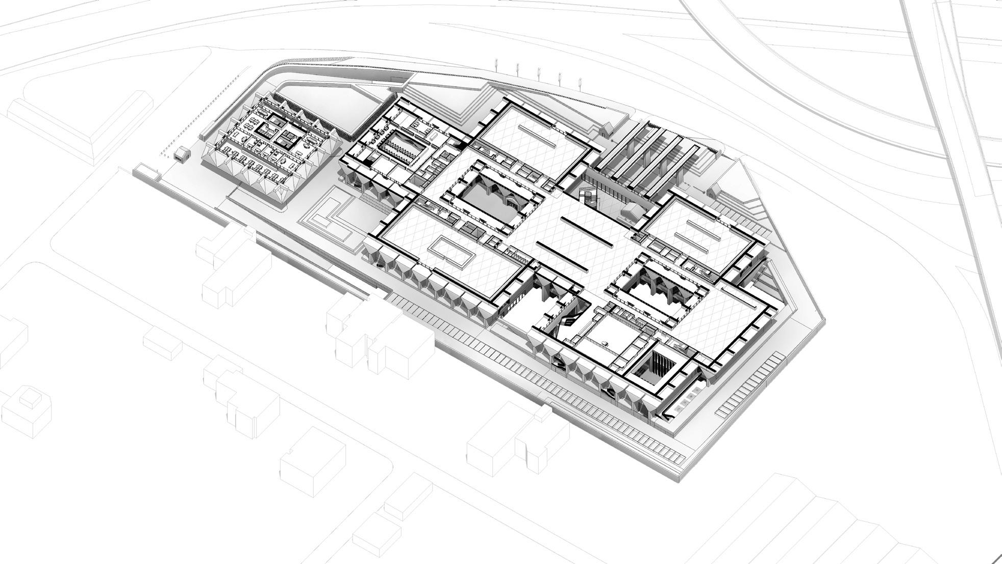
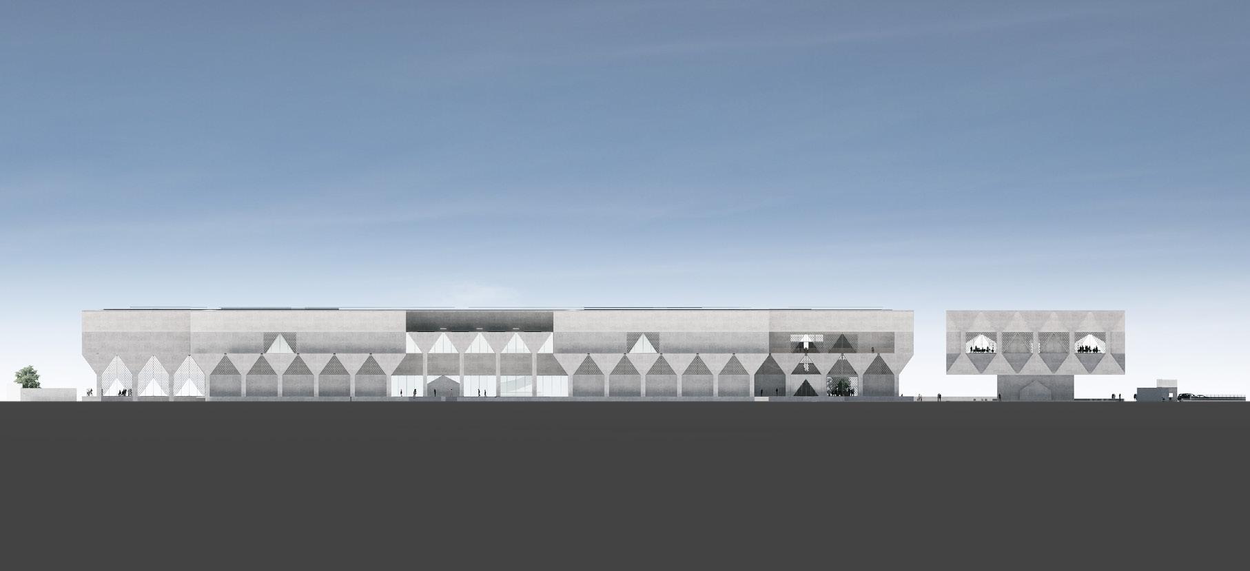
35 Stage 4 Drawing Package 02 +8,750 01 B2 -13,400 SE Max. Height Construction 1 2 3 4 5 6 7 8 9 10 11 12 13 15 16 17 18 20 21 22 23 24 B3 -17,400 19 26 27 28 29 30 25 31 14 A1 +6,200 23a 26a 29a 4a 4,375 4,375 4,375 4,375 3,100 3,400 6,900 4,000 8,000 8,000 8,000 8,000 8,000 8,000 8,000 8,000 8,000 8,000 8,000 8,000 8,000 8,000 8,000 8,000 8,000 8,000 8,000 8,000 8,000 8,000 8,000 7,250 7,250 8,000 8,000 8,000 8,000 8,000-X1 GF B1 Roof 01 +4,375 03 SE Max. Height Construction 1 2 3 4 5 6 7 8 9 10 11 12 13 15 16 17 18 20 21 22 23 24 LG 19 26 27 28 29 30 25 31 14 23a 26a 29a 1,490 4,375 4,375 4,375 4,375 1,100 2,000 3,400 6,900 4,000 GF +0 +241,300 GF +0 +241,300 02 02 B1 B1 03 03 B2 B2 Max. Height Construction Max. Height Construction 1 2 3 4 5 6 7 8 9 10 11 12 13 15 16 17 18 20 21 22 23 24 B3 B3 19 26 27 28 29 30 25 31 14 A1 BM BM 23a 26a 29a 4a 4,000 3,450 3,450 3,400 3,100 4,375 4,375 4,375 4,375 1,490X1 ISO A1 841mm 594mm LONG SECTION 07 -CORE B,C 12 500 LONG SECTION 04 -NORTH CORRIDOR 10 LONG SECTION 05 -SOUTH CORRIDOR 11 AUDITORIA BOH CIRCULATION ART STORAGE FOH GALLERIES OFFICE PARKING RESEARCH & EDUCATION STUDIOS TOILETS & PERSONAL PLANT EXTERNAL CIRCULATION & ELECTRICAL RISER MECHANICAL RISER WATER RISER ER MR WR 02 +8,750 01 B2 -13,400 SE Max. Height Construction 1 2 3 4 5 6 7 8 9 10 11 12 13 15 16 17 18 20 21 22 23 24 B3 -17,400 19 26 27 28 29 30 31 14 A1 +6,200 23a 26a 29a 4a 4,375 4,375 4,375 4,375 3,100 3,400 6,900 4,000 8,000 8,000 8,000 8,000 8,000 8,000 8,000 8,000 8,000 8,000 8,000 8,000 8,000 8,000 8,000 8,000 8,000 8,000 8,000 8,000 8,000 8,000 8,000 7,250 7,250 8,000 8,000 8,000 8,000 8,000-X1 GF B1 Roof 01 +4,375 03 SE Max. Height Construction 1 2 3 4 5 6 7 8 9 10 11 12 13 15 16 17 18 20 22 23 24 LG 19 26 27 28 29 30 31 14 23a 26a 29a GF +0 +241,300 GF +0 +241,300 02 02 B1 B1 03 03 B2 B2 Max. Height Construction Max. Height Construction 1 2 3 4 5 6 7 8 9 10 11 12 13 15 16 17 18 20 21 22 23 24 B3 B3 19 26 27 28 29 30 31 14 A1 BM BM 23a 26a 29a 4a 4,000 3,450 3,450 3,400 3,100 4,375 4,375 4,375 4,375 1,490X1 The Edison, 223-231 Old Marylebone London -NW1 5QT UK ISO A1 841mm 594mm Project Architect: S Ghosh & Associates R4, Hauz Khas New Delhi -110016 India Project Architect: Mahendra Raj Q-24, Jangpura Extension New Delhi -110014 India Structural Consultant: AEON MEPF Consultant: A-23, 3rd Floor, Sector 9 Noida -201301 India General Notes: This drawing represents Adjaye This drawing must be read in relevant design team drawings. Any discrepancy in or between the attention of the architect All other services shown are agencies prior to the commencement All dimensions shown are in indicated otherwise. Only figured For setting out information refer drawing. The contractor shall submit prior to commencement of any fittings, fixtures and components approved shop drawings. All materials shall be approved The levels shown on the drawings Key: Integrated 5 LONG SECTION 07 -CORE B,C 12 1 500 LONG SECTION 04 -NORTH CORRIDOR 10 LONG SECTION 05 -SOUTH CORRIDOR 11 4 CULTURAL CENTER SECOND FLOOR SMALL AUDITORIUM PERMANENT GALLERIES SPECIAL GALLERIES / TEMPORARY GALLERIES OFFICE RESEARCH AND EDUCATION Exhibition/ Commissioned workspaces Auditorium Lobby Small Auditorium Special exhibition AV Room Foyer West Patio Research & Education Special exhibition Office Special exhibition Permanent gallery East Patio
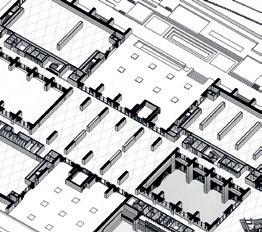
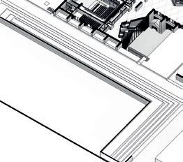
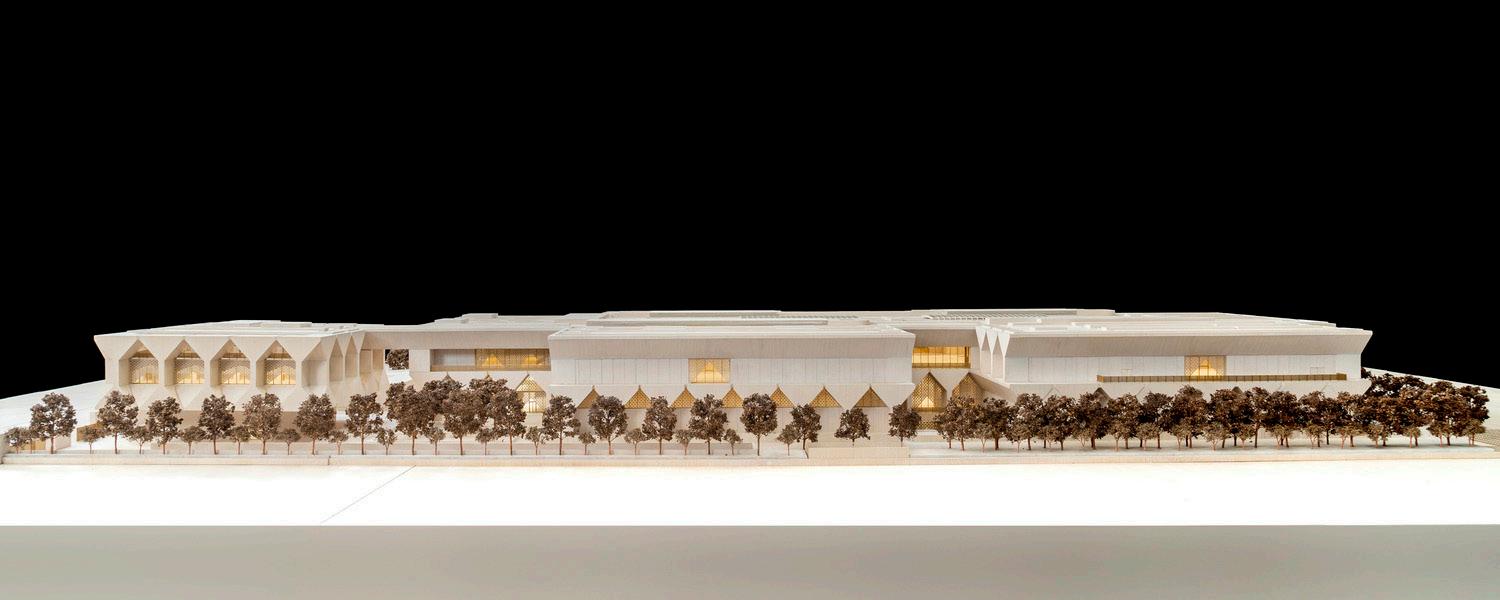
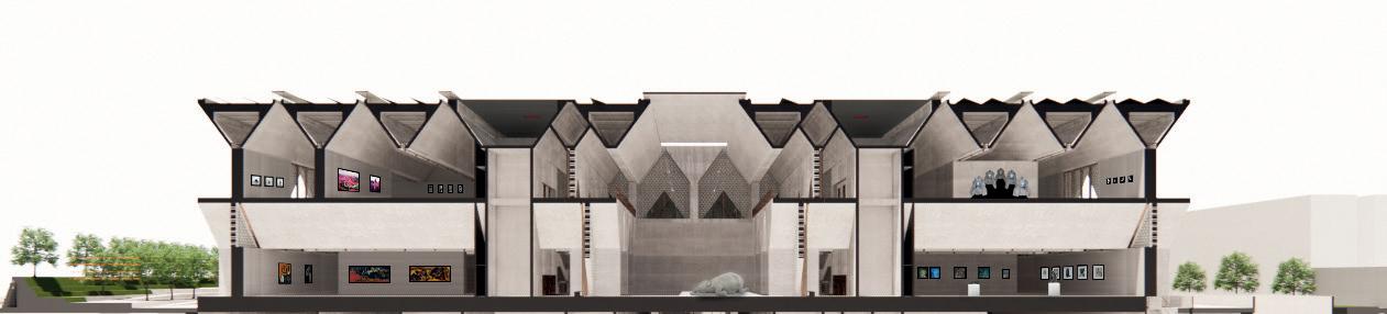
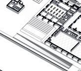
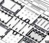
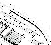
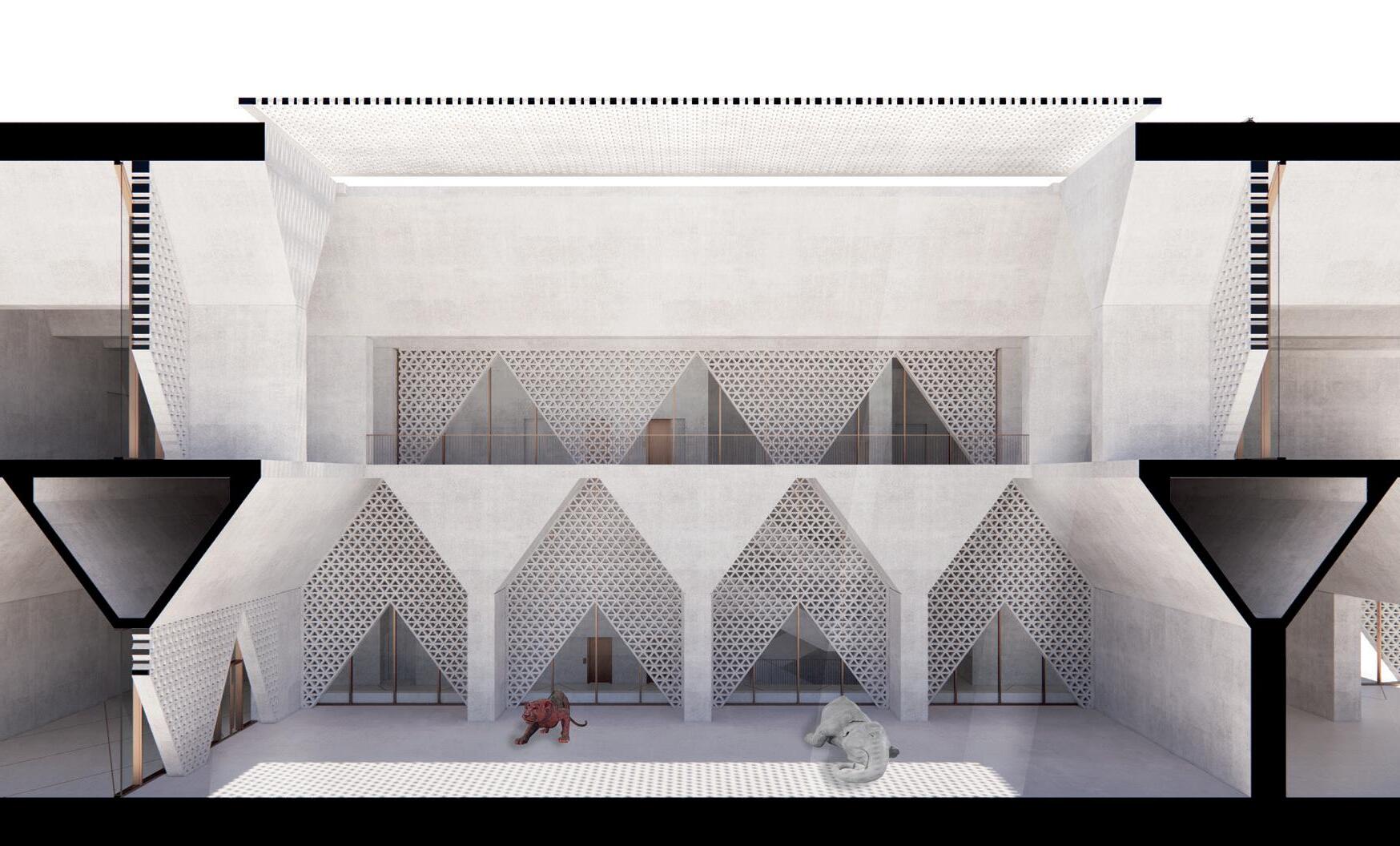
36 INTRODUCTION INTRODUCTION GALLERIES SHORT SECTION Interior Patio Circulation Balcony Retractable Roof System Balcony Special Exhibition 04 Special Exhibition 05 Circulation Temporary Exhibitions Core Circulation Circulation Core Special Exhibition 02 Second Floor Roof Ground Floor LONG SECTION West Patio Long Section Ground Floor Second Floor
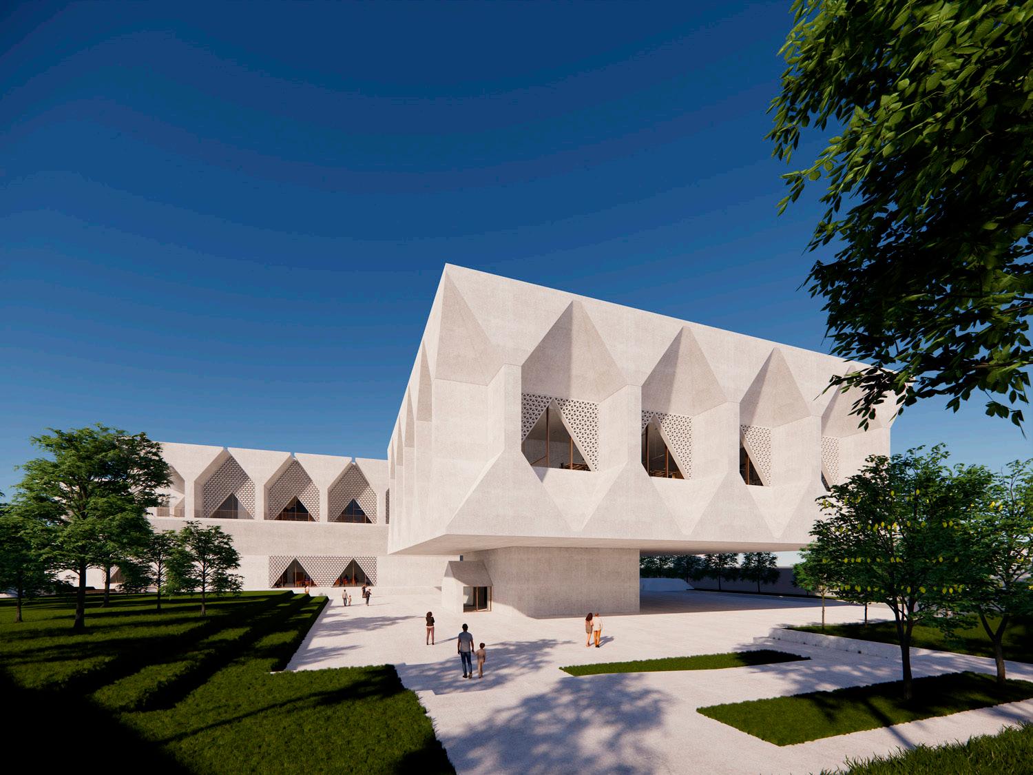
37
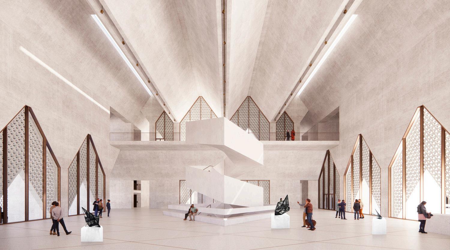
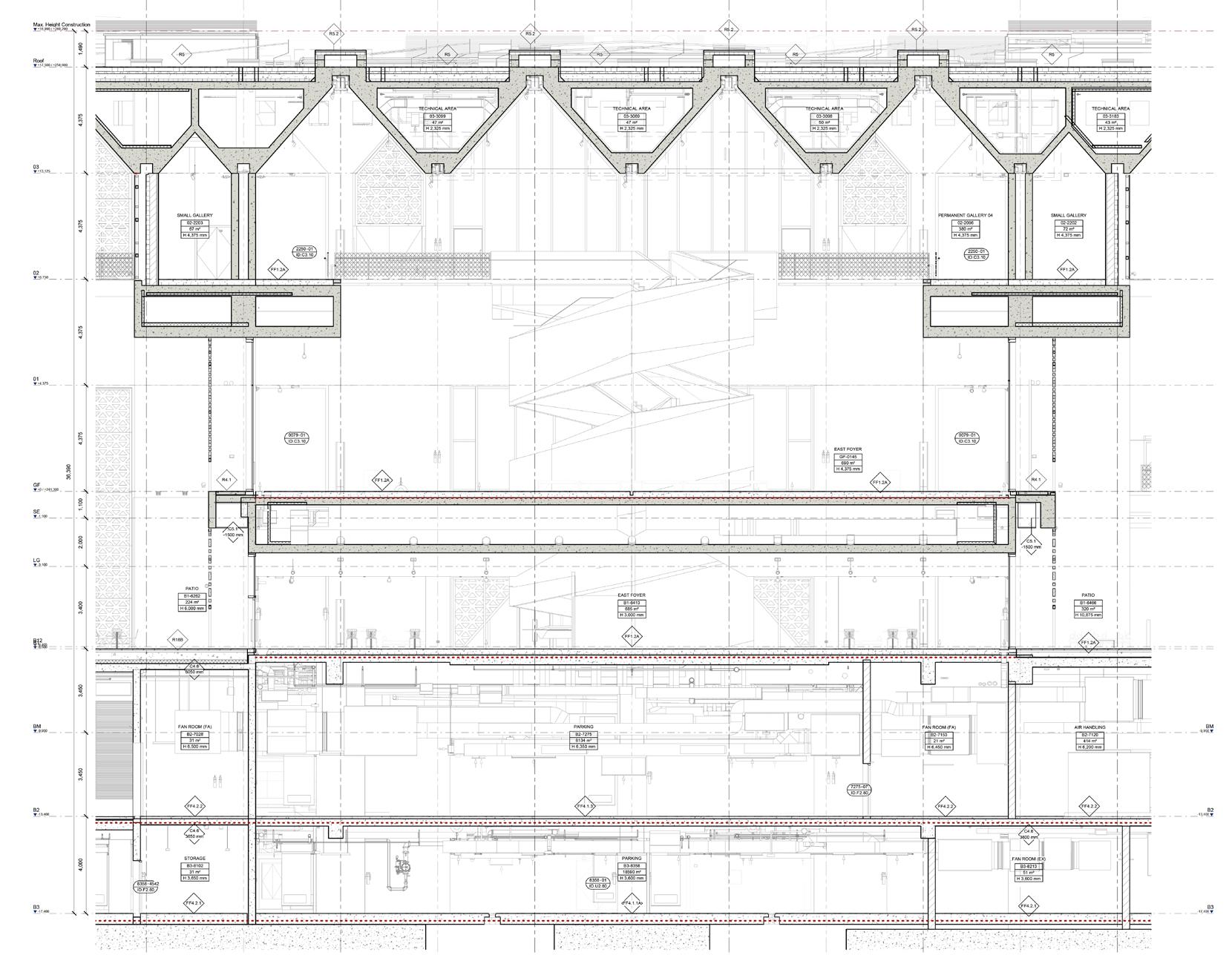
Stage 4 Technical Drawings
38


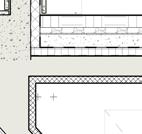
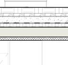
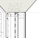
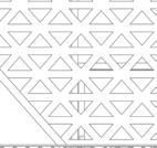
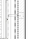
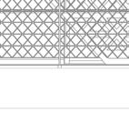
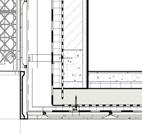


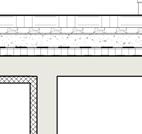
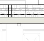
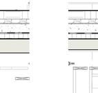
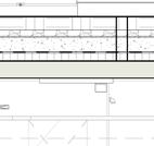
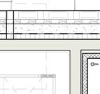
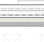
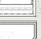
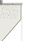
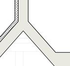
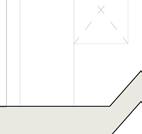
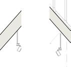
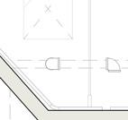
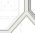
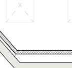
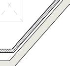

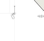
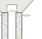

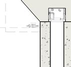


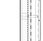
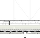
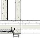
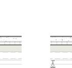
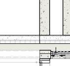
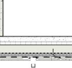
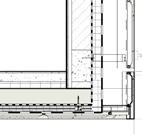


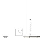
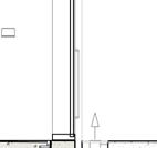
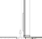
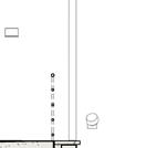

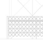
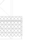
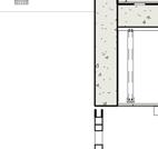
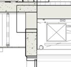
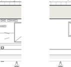
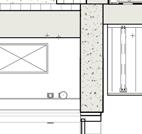
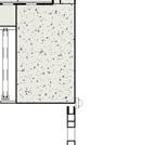


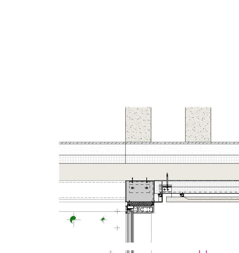


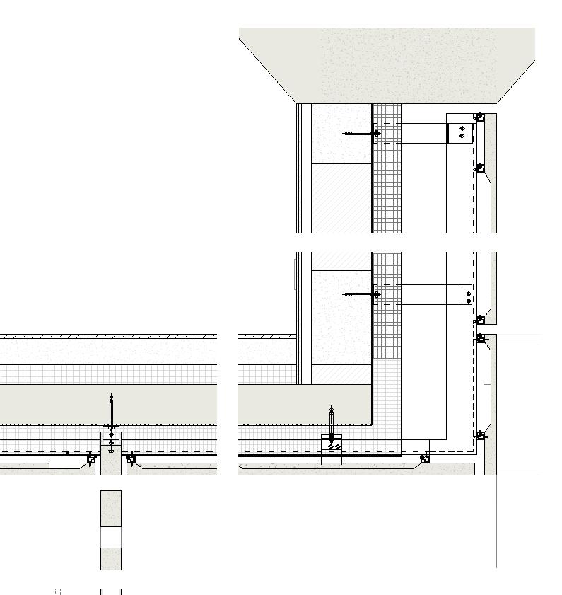

39 4 42-312 02 +8,750 01 03 SE Max. Height Construction +18,990 +260,290 A2 A1 +6,200 H1 R4.1 C5.1 -1500 mm EW1.11 FF1.2A -700 mm R5 FF1.2A 67 m² 02-2203 SMALL GALLERY H 4,375 mm 380 m² 02-2096 PERMANENT GALLERY 04 H 4,375 mm 690 m² GF-0145 EAST FOYER H 4,375 mm 3,065 100 1,440 305 100 1,530 305 JT1.1 JT8.1 FT8.3 FT1.1 02 +8,750 01 03 SE Max. Height Construction +18,990 +260,290 D D1 3 42-507 FF1.2A EW1.11 R4.1 C5.1 -1500 mm R5 2% 1 42-507 2 42-507 42-507 72 m² 02-2202 SMALL GALLERY H 4,375 mm 380 m² 02-2096 PERMANENT GALLERY 04 H 4,375 mm EAST FOYER PATIO 305 1,530 100 3,065 305 1,530 100 FT1.3 JT1.1 FT8.1 JT8.1 ISO A1 841mm 594mm 500 Cross Section -A Refer to Facade Consultant Documentation GF +0 +241,300 R4.1 FT1.3 22-07 50 00 RFS-221 - Membrane Inverted Roof System on Concrete Non-Woven Geotextile 300gsmVoid Former22-03 53 00 SCR-174 - External Void Former-Raised Floating Concrete Wearing Roof Screed - White FE03 ISO A1 841mm 594mm D1 22-07 21 11 INS GFRC Panel Lining System EW Waterproofing EW Vapour Barrier 335 GF +0 +241,300 R4.1 FT1.3 22-07 50 00 RFS-221 - Membrane Inverted Roof System on Concrete Non-Woven Geotextile 300gsmVoid Former22-03 53 00 SCR-174 - External Void Former-Raised Floating Concrete Wearing Roof Screed - White FE03 T ISO A1 841mm 594mm 1 10 42-507 -North Facade Section -Ceiling detail 1.10 3 D1 22-07 21 11 INS-201 GFRC Panel Lining System EW Waterproofing EW Vapour Barrier335 GF +0 +241,300 R4.1 FT1.3 22-07 50 00 RFS-221 - Membrane Inverted Roof System on Concrete Non-Woven Geotextile 300gsmVoid Former22-03 53 00 SCR-174 - External Void Former-Raised Floating Concrete Wearing Roof Screed - White FE03 ISO A1 841mm 594mm 10 42-507 -North Facade Section -Ceiling detail 1.10 3 03 D EW Vapour BarrierEW Waterproofing22-04 20 00 BLK-339 - Medium Density Concrete Common Blockwork300mm 22-07 21 11 INS-101 - Internal Thermal Insulation of External Wall Furring Channels22-09 29 00 LIN-203 - Standard Gypsum Plasterboard - 12.5mm 22-09 29 00 LIN-203 - Standard Gypsum Plasterboard - 12.5mm EW1.11 50 50 D1 FF1.2A -700 mm - - - Internal Floating Levelling Screed 22-03 54 00 SCR-101 - Internal Floating Levelling Screed 22-03 54 00 SCR-101 - Internal Floating Levelling Screed Void FormerJT1.1 22-07 21 11 INS-201 - Rigid Insulation Soffit Board GFRC Panel Lining System - Refer to Facade Consultant DocumentationEW WaterproofingEW Vapour Barrier335 GF R4.1 FT1.3 22-07 50 00 RFS-221 - Membrane Inverted Roof System on Concrete Non-Woven Geotextile 300gsmVoid Former22-03 53 00 SCR-174 - External Void Former-Raised Floating Concrete Wearing Roof Screed - White ISO A1 841mm 594mm 42-507 -North Facade Section -Top detail 1.10 1 1 10 42-507 -North Facade Section -Edge detail 1.10 2 10 42-507 -North Facade Section -Ceiling detail 1.10 3
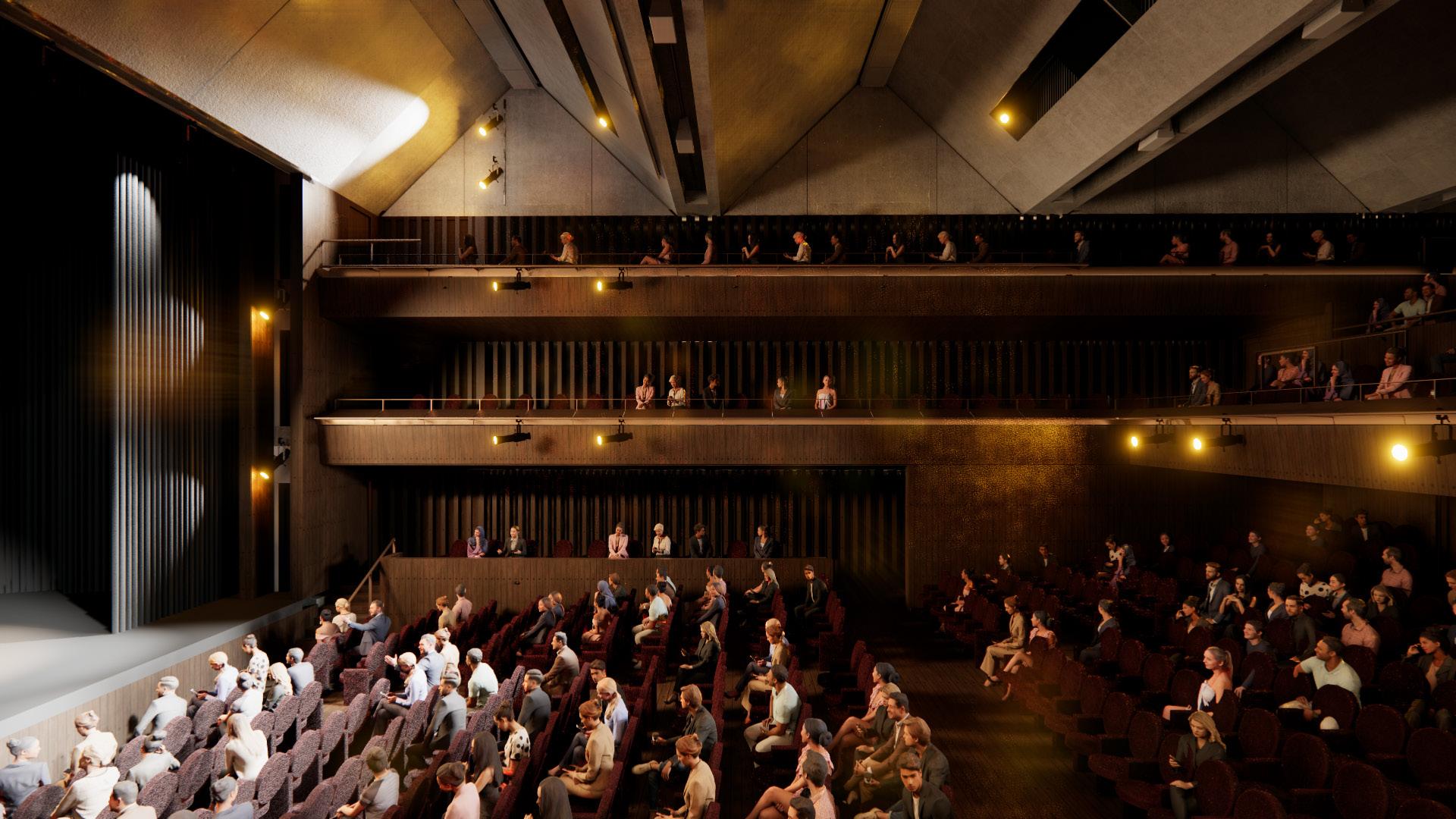
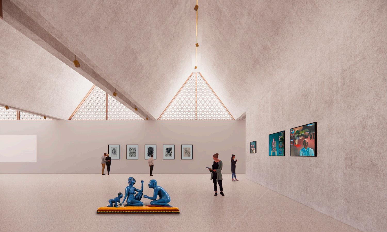
40
41 GF 02 01 13 15 16 17 18 20 19 14-ID.C2.104,375 4,375H 4,375 mmH 2,965 mm - - 41 m²-2,965 mm GF +0 +241,300 +4,375 J K L K1 FT5.1FF1.2A 4,375 4,375 998 m²60 m²C4.702 01 -1,100 13 15 16 17 18 20 19 14 -0074 02 IW1.1ID.J.60GF-0073 TEMPORARY GALLERY 01 H 4,375 mm 01-1078 TECHNICAL AREA H 2,965 mm 01-1077 TECHNICAL AREA 2,965 mm 01-1076 TECHNICAL AREA 2,965 mm 01-1075 TECHNICAL AREA H 2,965 mm 01-1074 TECHNICAL AREA H 2,965 mm 01-1073 TECHNICAL AREA H 2,965 mm 01-1121 TECHNICAL AREA H 2,965 mm 4,375 4,375 GF +0 +241,300 +4,375 J K L K1ID.C2.10 4,375 4,375 998 m²GF-0074 SERVICE ZONE 4,375 mm FF1.2A -0057 03 The Edison, London UK ISO A1 841mm 594mm Last Plotted: Filename: Project S R4, Hauz India Project Mahendra Q-24, India Structural AEON MEPF A-23, India General This This relevant Any discrepancy the attention All other agencies All dimensions indicated For setting drawing. The contractor prior fittings, approved All materials The levels Key: N Drawing Scale: Date: Drawing Project: Client: Status: Turner Project 2nd Floor, India A-302, India 6 A D CC C--GALLERY TEMPORARY KIRAN STAGE VAMA NCC 100 52XXX-AA-GF-0073-N 1 52XXX-AA-GF-0073-E 2 52XXX-AA-GF-0073-S 3 52XXX-AA-GF-0073-W 4 P4.116.09.2022Information P4.214.10.2022Stage P4.307.11.2022End P4.425.11.2022End C127.01.2023Advanced GF FF2 FF2.4.2 FF2.4 FF2.4.2ID.L2.20 5040 01 FF2 FF2.4ID.L2.20 5076 01 FF2.4ID.L2.20 6242 01ID.L1.20 5032 01 376 m² LG-5041 LARGE AUDITORIUM STALLS 35 m² LG-5040 SOUND & LIGHT LOBBY C2.6 2760 mm C2.5 2475 mm PS02/DP01 USHERS SEAT TB07/DP01/PS02 TB06/AF03/PS02 PS02 TB02 MATTE BLACK PAINT BEHIND TIMBER LINING GF 01 5 6 7 A1 +6,200ID.L2.20 5076 01 FF2.4ID.L2.20 01 FF2.4.2ID.L2.20 58 FF2.4ID.M1.80 0234 02ID.M1.80 6265 02 161 m² GF-0142 LARGE AUDITORIUM BALCONY 376 m² LG-5041 LARGE AUDITORIUM STALLS 35 m² LG-5040 SOUND & LIGHT LOBBY 37 m² B1-6229 ORCHESTRA PIT 228 m² AB-1129 LARGE AUDITORIUM BALCONY 01 42 m² A1-1705 TECHNICAL AREA 43 m² A1-1706 TECHNICAL AREA 43 m² A1-1710 TECHNICAL AREA 19 m² A1-1719 TECHNICAL AREA 60-601 DP01 DP01 CW02 CW02 BAL-111 BAL-111 BAL-125 BAL-111 BAL-113 BAL-111 BAL-111 BAL-113 BAL-111 BAL-125 BAL-143 BAL-143 C2.5 2305 mm C2.6 2225 mm PS02/DP01TO DETAIL 60-601 AND THEATRE CONSULTANT'S INFORMATION PS02/DP01 CLG-811 CLG-811 CLG-811 CLG-811 CLG-811 SEATING WAGON, REFER TO THEATRE CONSULTANT'S FIXED REMOVABLE STEPS, REFER TO DRAWING 60-200 REMOVABLE SEAT FOR SOUND DECK, REFER TO THEATRE CONSULTANT'S INFORMATION REMOVABLE AREA OF SEATING AND FLOOR FOR WHEELCHAIR SPACE REMOVABLE SEAT FOR WHEELCHAIR SPACE BAL-111FF2.4 TB08 TB08 TB02 TB02 BZ02 BZ02 TB02 PS02 GC01 GC01 GC01 FOR LIGHTING EQUIPMENT FIXTURES TB06/AF03/PS02 GC01 TB07 MATTE BLACK PAINT TO ALL MATTE BLACK PAINT TO ALL BAL-111 VENTILATION PLENUM VENTILATION PLENUM The Edison, 223-231 London -NW1 5QT UK Last Plotted: Filename: Project Architect: S Ghosh R4, Hauz Khas New Delhi -110016 India Project Architect: Mahendra Q-24, Jangpura New Delhi -110014 India AEON A-23, 3rd Floor, Noida -201301 India Integrated Drawing No.: Date: Drawing Title: Project: Client: Status:Turner Project Manager: 2nd Floor, Corporate Noida -201303 A-302, Delphi, Orchard Mumbai -400076 0 2 Cd a C CZX-27.01.2023 1:50 @ MAIN AUDITORIUM KIRAN NADAR STAGE 4 VAMA SUNDARI NCC AA 50 Main Auditorium Elevation -North -Wall Lining 1 Main Auditorium Elevation -North -Balcony Fronts 2 RevisionDate P4.116.09.2022Information P4.214.10.2022Stage P4.307.11.2022End P4.425.11.2022End P4.516.12.2022Information C127.01.2023Advanced GF +0 +241,300 +4,375 SE 13 15 16 17 18 20 19 14-0063 01ID.J.60 FF1.2A 4,375 4,375 60-50501-1077 TECHNICAL AREA H 2,965 mm 01-1076 TECHNICAL AREA H 2,965 mm 01-1075 TECHNICAL AREA H 2,965 mm 01-1074 TECHNICAL AREA 2,965 mm 01-1073 TECHNICAL AREA 2,965 mmJ K L K1 IW1.1ID.J.60 3,395 8,000 4,000 3,500 4,375 4,375 998 m²60 m²-0063 01 GF 02 +8,750 01 13 15 16 17 18 20 19 14FT2.1 FT2.1 FT2.1 FT2.1 FT2.1 FT2.1 FT2.1-H 4,375 mmH 2,965 mm2,965 mm2,965 mmH 2,965 mmH 2,965 mmH 2,965 mmH 2,965 mm 4,375 4,375 FF1.2A J K L K1 -0063 01 4375 mm 4,375 4,375 998 m²4,375 mm 3000 mmThe Edison, London ISO A1 841mm 594mm Last Plotted: Filename: Project S R4, Hauz New Project Mahendra Q-24, New India Structural AEON MEPF A-23, Noida India General This This relevant Any discrepancy the attention All other agencies All dimensions indicated For setting drawing. The contractor prior fittings, approved All materials The levels Key: Drawing Scale: Drawing Project: Turner Project 2nd Floor, India A-302, Mumbai India 2 9 Ce--A0 0 GALLERY TEMPORARY KIRAN STAGE VAMA NCC 52XXX-AA-GF-0073-N 1 52XXX-AA-GF-0073-E 2 52XXX-AA-GF-0073-S 3 52XXX-AA-GF-0073-W 4 RevisionDate P4.116.09.2022Information P4.214.10.2022Stage P4.307.11.2022End P4.425.11.2022End C127.01.2023Advanced

AISHTI FOUNDATION
35.000m2 Cultural Complex
Beirut, Lebanon
RIBA Stages 1-6
2013
The juxtaposition of art and shopping presented the practice with the challenge to create a design for an entirely new typology that would integrate two, often conflicting, worlds. The concept, therefore, has been to establish a lively architectural dialogue – via a celebration of views into the different spaces (both gallery and retail) as well as a homogenising tiled design that presents a continuous language throughout the building’s floor, façade and roof.
The opportunity for flexibility has been a key consideration, so that entrances to the separate uses can be distinct, but there is also the opportunity to connect the entire programme. Doorways, screens and boundaries are therefore highly flexible, demountable, sliding and adaptable. The Aishti Foundation building is located on a brownfield coastal site in central Beirut and replaces a number of previous warehouses, while also fronting onto an enhanced seaside promenade that has been created through land reclamation and the insertion of a playful, undulating landscaping strategy. This immediately defines the site as an amenity and a draw for visitors. In addition, the top level offers a sky bar with striking sea views as well as over the city of Beirut.
The form is a simple block that has been rotated on one edge so that it appears tilted. The retail floors are to one side of the building, configured around a central atrium. The other side of the building accommodates the Aishti Foundation galleries.
42
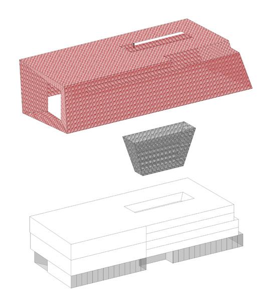
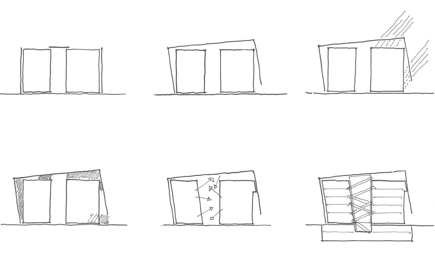
The main entrance is punched into the façade and sits within the corner of the building, drawing visitors through the interior on a diagonal axis, which offers views to the sea. While the retail section of the building is wrapped in a solid façade and draws light from the atrium, the east façade is defined by a single large window, behind which a staircase ascends the galleries, offering a moment where the building connects back to the city.
The façade has a number of layers, so that the building is like a glazed box that sits within a louvred frame. The outer layer creates an efficient passive shading system. Laterally supported, it floats around the building, with a void existing between the two layers. The geometric ‘thunderbolt’ pattern of the ceramic louvres – or ‘baguettes’ – reappears in the landscaping across the entire site, as well as on the interior tiling, and becomes a defining motif.
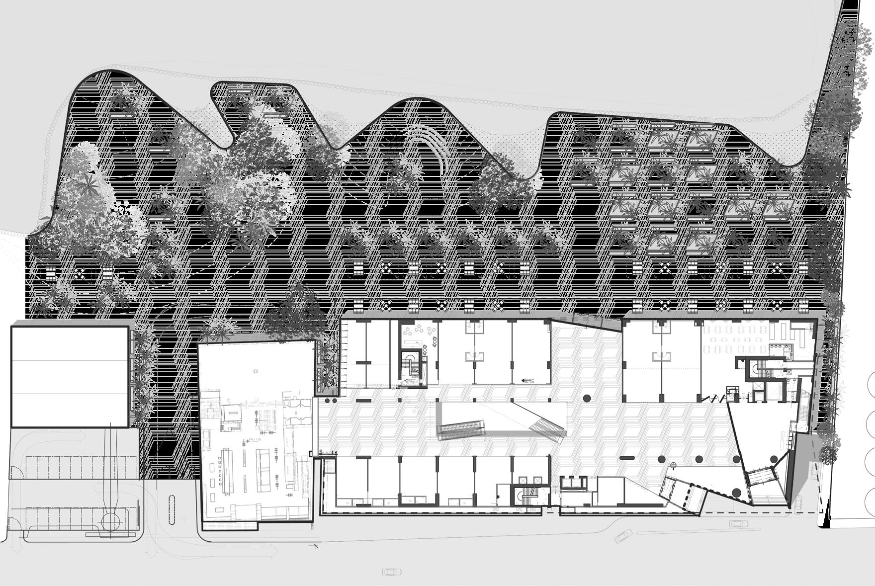
43
13 Adjaye Associates Aishti Foundation, Beirut October 2012 Concept Diagrams Typical facade with screen Screen combined and tilted Shading and protection Use of external voids Views and connection internal void Figure Retail Restaurant Plant Skybar Terrace
Site Plan
Concept Diagrams


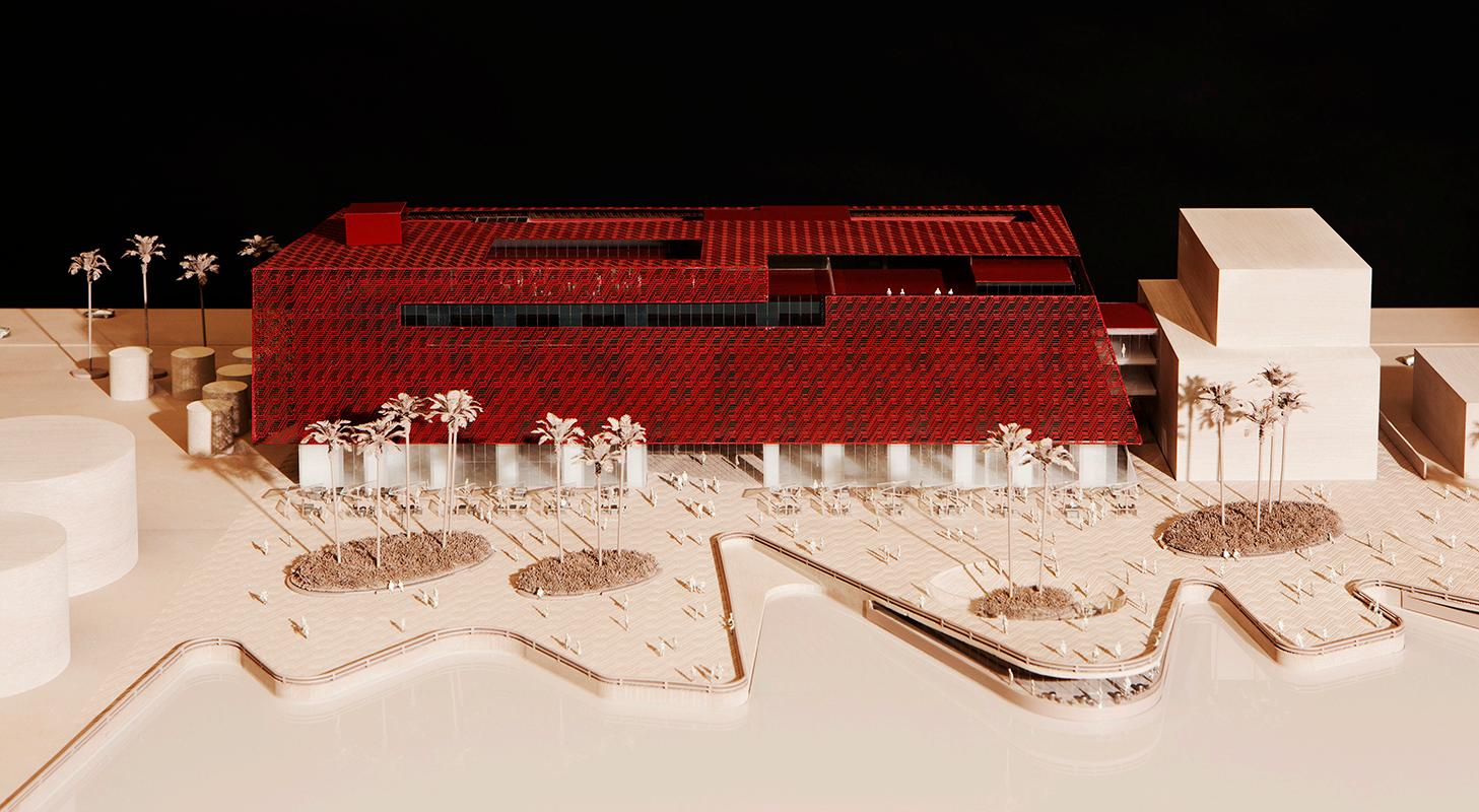
44 26 Adjaye Associates Aishti Foundation, Beirut / October 2012 A-A Section / 1:500 21 Adjaye Associates Aishti Foundation, Beirut / October 2012 Fourth Floor Plan / 1:500 Fourth Floor Plan Longitudinal Section Presentation Model
45 B C D A E E1 Section through connecting bridge link to existing building Secondary Secondary Primary building envelope 97.0° 97.0° 8275 (varies) 5559 (varies) 1650 +6.000m 500 1969 2953 Light. landscaping. specification. 3400 CURTAIN WALL GLAZING SYSTEM AFB GLAZING SYSTEM TYPES SUMMARY SYSTEM LOCATION ALL LEVELS/ FRAMED WINDOW SYSTEM LEVEL 1 CURTAIN WALLING GLAZING WITH EXTERNAL VERTICAL FINS/ NO TRANSOMS LEVEL 1 CURTAIN WALL GLAZING SYSTEM WITH MOTORISED SLIDING DOORS GROUND BALUSTRADE; STRUCTURAL GLAZING LEVEL 5; GLAZED SKYLIGHT LEVEL 5; TYPE B TYPE C TYPE D TYPE E TYPE F TYPE A DESCRIPTION GENERAL NOTE: FOR FURTHER INFORMATION ON ROOF LEVEL ENVELOPE AND ENTRANCE AREA ELEVATIONS REFER TO DRAWINGS: AFB-19-001 AFB-19-002 AFB-20-006 AFB-20-008 B C E E1 B C D A E E1 screen (see above) 8275 (varies) 5559 (varies) 25650 5650 19000 through connecting bridge link to existing building Back-painted glazing glazing MU Wall with render finish; Access door for maintenance; solid; steel; PPC colour TBC. Cyclindrical Outrigger plates; dwgs/spec. SKYLIGHT LIFT SHAFT OVER-RUN TYPE glazing 1250 300 2100 discharge air Penetration for chilled water Ladder for maintenance access Level HVAC unit to relocated Primary 30.000 NORTH PLOT BOUNDARY m m Secondary 4200 4200 4350 5600 C D A E1 SECTION PERPENDICU (WITH PERPENDIC NGLED CUTS CONTINUOUS SOUTHELEVATIONS 6000 1100 02 20-003 02 20-003 SOUTH ELEVATION SECONDARY SCREEN SYSTEM Scale: 1:200 01 SOUTH ELEVATION PRIMARY FACADE SYSTEM Scale: 1:200 02 NORTH ELEVATION SECONDARY SCREEN SYSTEM Scale: 1:200 03 NORTH ELEVATION PRIMARY FACADE SYSTEM Scale: 1:200 04 01 13-004 01 Elevation South/North Facade Section East/North B C D A E E1 Section through connecting bridge link to existing building Secondary Secondary Primary building envelope 97.0° 97.0° 8275 (varies) 5559 (varies) 1650 +6.000m 500 1969 2953 Light. landscaping. specification. 3400 CURTAIN WALL GLAZING SYSTEM AFB GLAZING SYSTEM TYPES SUMMARY SYSTEM LOCATION ALL LEVELS/ FRAMED WINDOW SYSTEM LEVEL 1 CURTAIN WALLING GLAZING WITH EXTERNAL VERTICAL FINS/ NO TRANSOMS LEVEL 1 CURTAIN WALL GLAZING SYSTEM WITH MOTORISED SLIDING DOORS GROUND BALUSTRADE; STRUCTURAL GLAZING LEVEL 5; GLAZED SKYLIGHT LEVEL 5; TYPE B TYPE C TYPE E TYPE F TYPE A DESCRIPTION GENERAL NOTE: FOR FURTHER INFORMATION ON ROOF LEVEL ENVELOPE AND ENTRANCE AREA ELEVATIONS REFER TO DRAWINGS: AFB-20-006 AFB-20-008 B C E E1 B C D A E E1 screen (see above) 8275 (varies) 5559 (varies) 25650 5650 19000 through connecting bridge link to existing building Back-painted glazing glazing MU Wall with render finish; Access door for maintenance; solid; steel; PPC colour TBC. Cyclindrical Outrigger plates; dwgs/spec. SKYLIGHT LIFT SHAFT OVER-RUN TYPE glazing 1250 300 2100 Louver for FA-AHU-01 discharge air for Ladder for maintenance access Level HVAC unit to relocated Primary NORTH PLOT BOUNDARY m m Secondary 4200 4200 4350 5600 C D A E1 SECTION PERPENDICU (WITH PERPENDIC NGLED CUTS CONTINUOUS SOUTHELEVATIONS 6000 1100 02 20-003 02 20-003 SOUTH ELEVATION SECONDARY SCREEN SYSTEM Scale: 1:200 01 SOUTH ELEVATION PRIMARY FACADE SYSTEM Scale: 1:200 02 NORTH ELEVATION SECONDARY SCREEN SYSTEM Scale: 1:200 03 NORTH ELEVATION PRIMARY FACADE SYSTEM Scale: 1:200 04 01 13-004 01
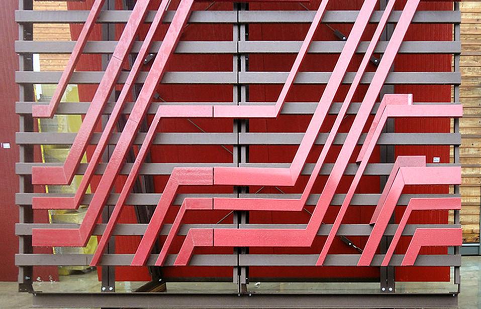
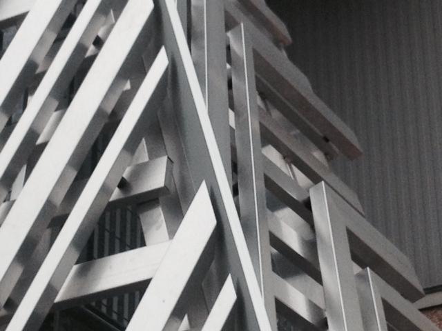
46
Facade Mock-ups Close up
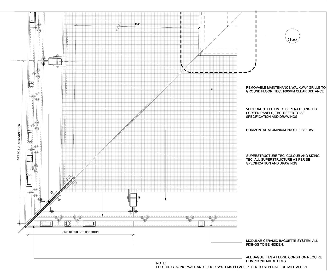
Typical Facade Module Typical Corner Detail
47
Key
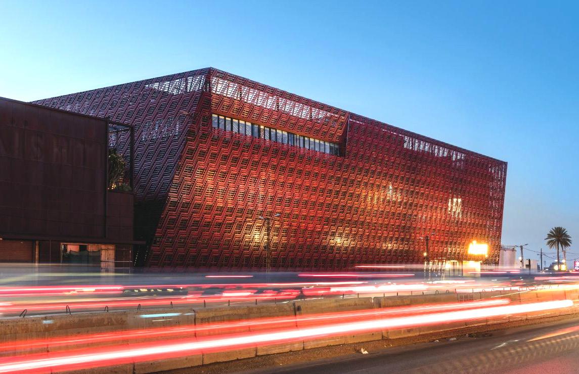
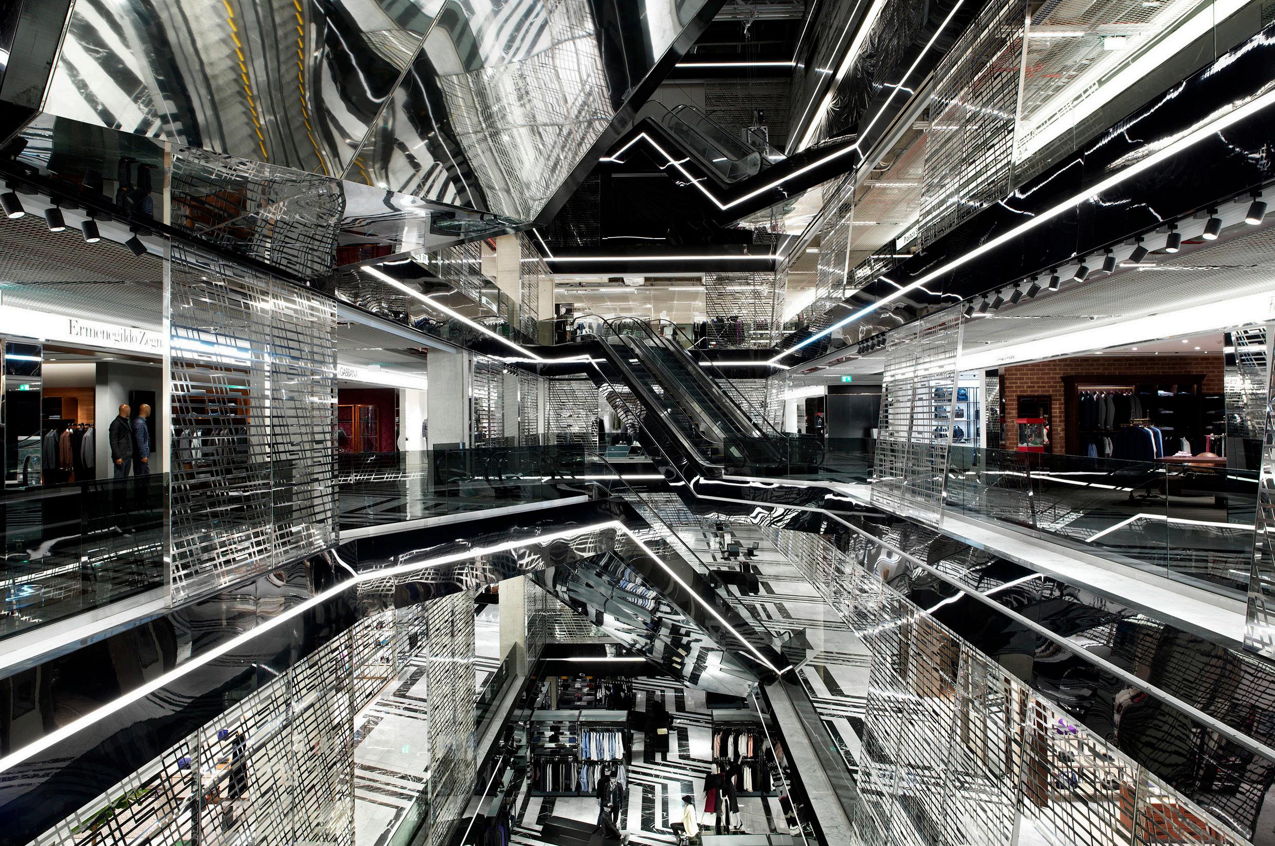
48
Main Facade View
Interior Atrium View
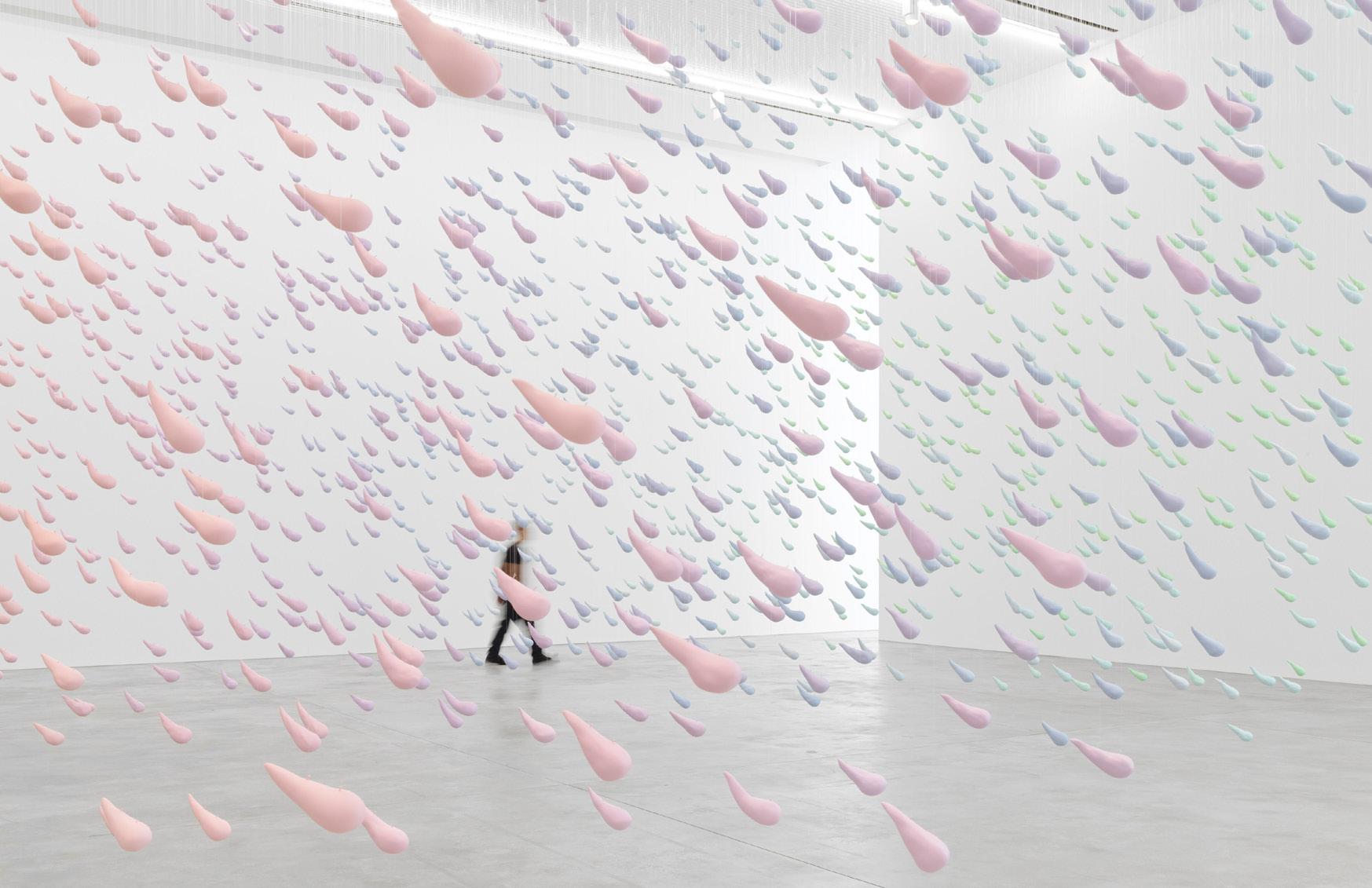
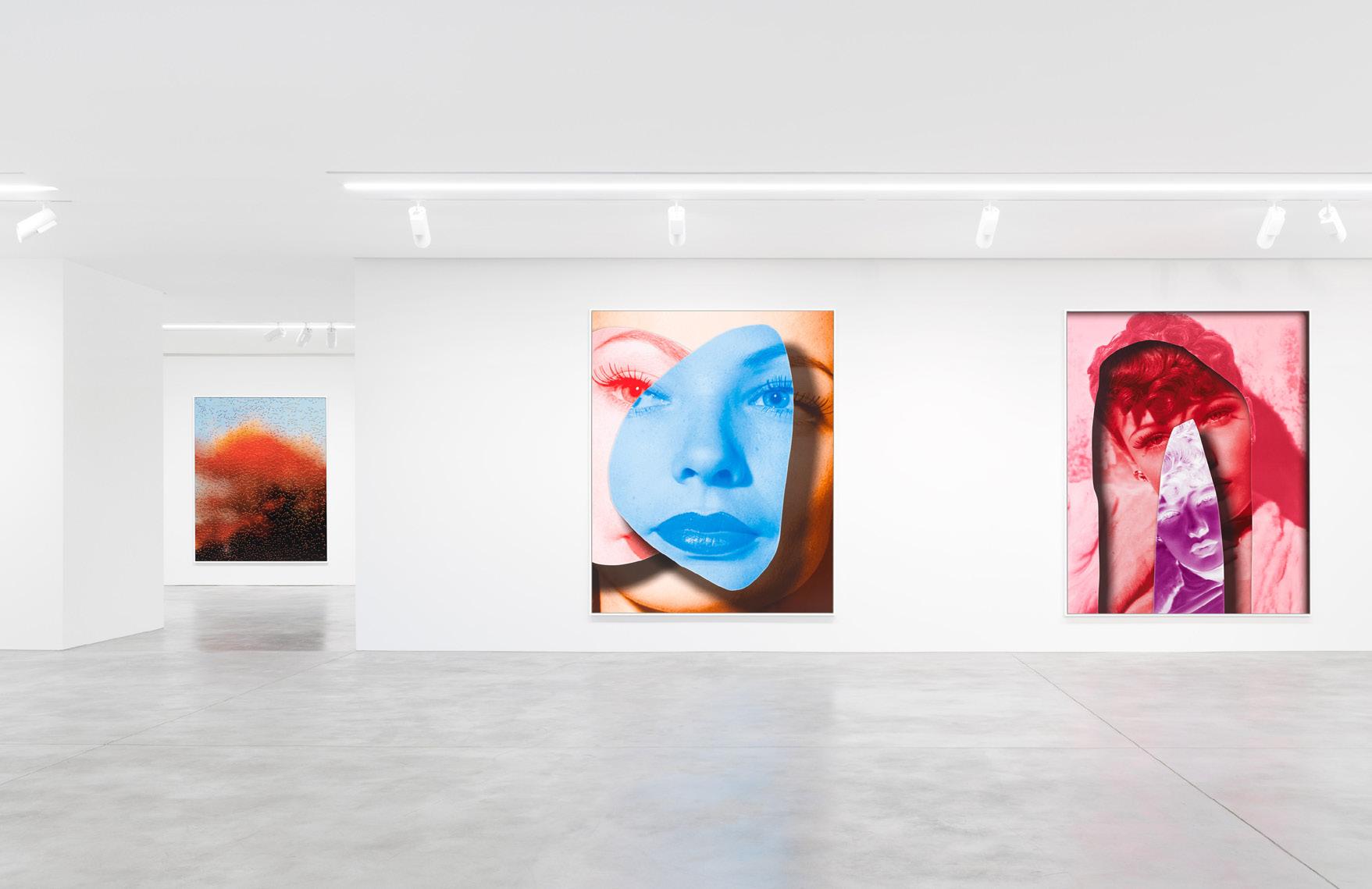
49
Gallery View
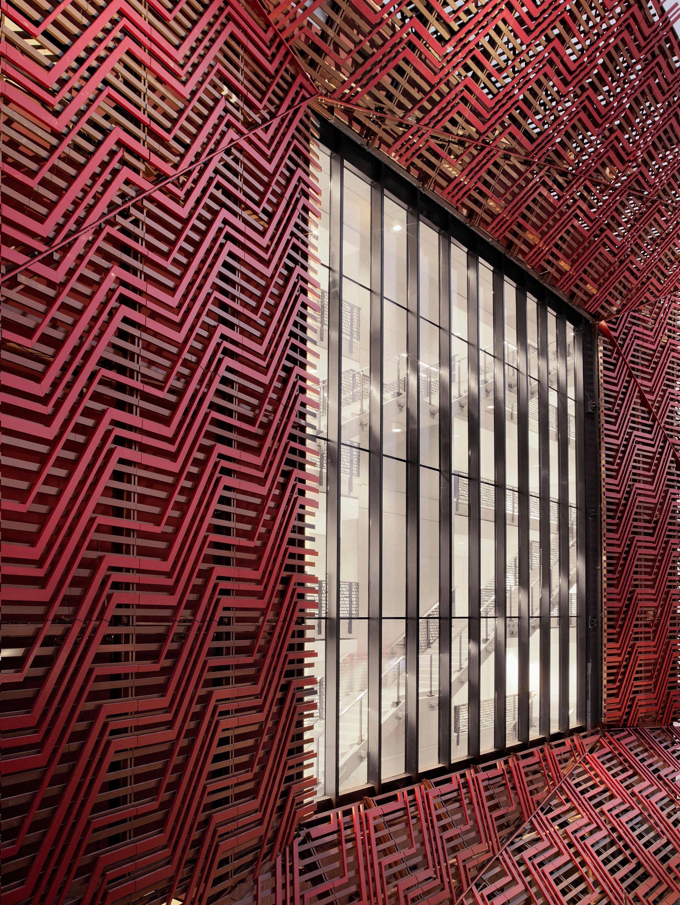
50
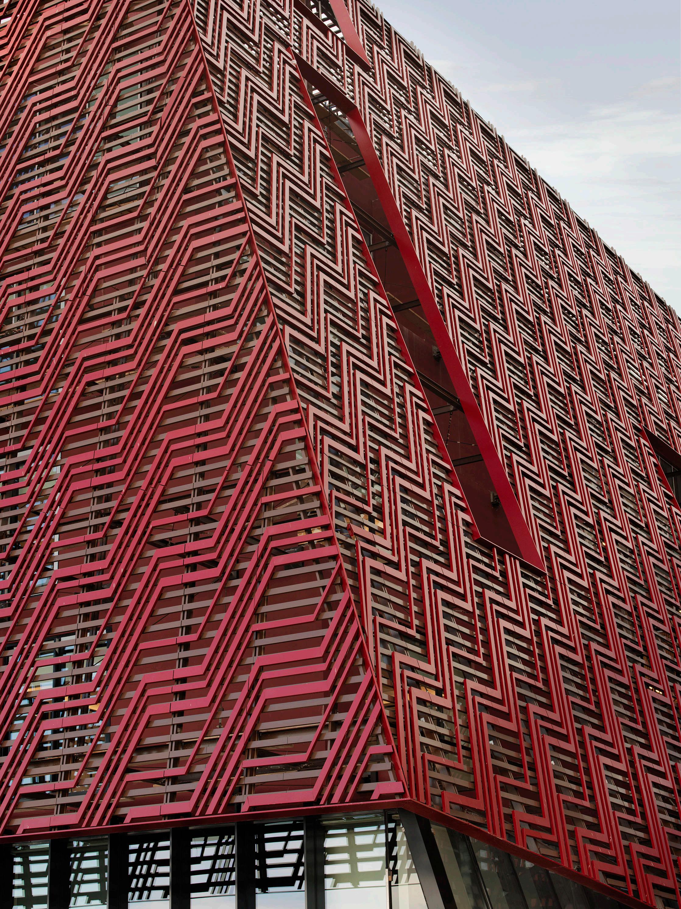
51
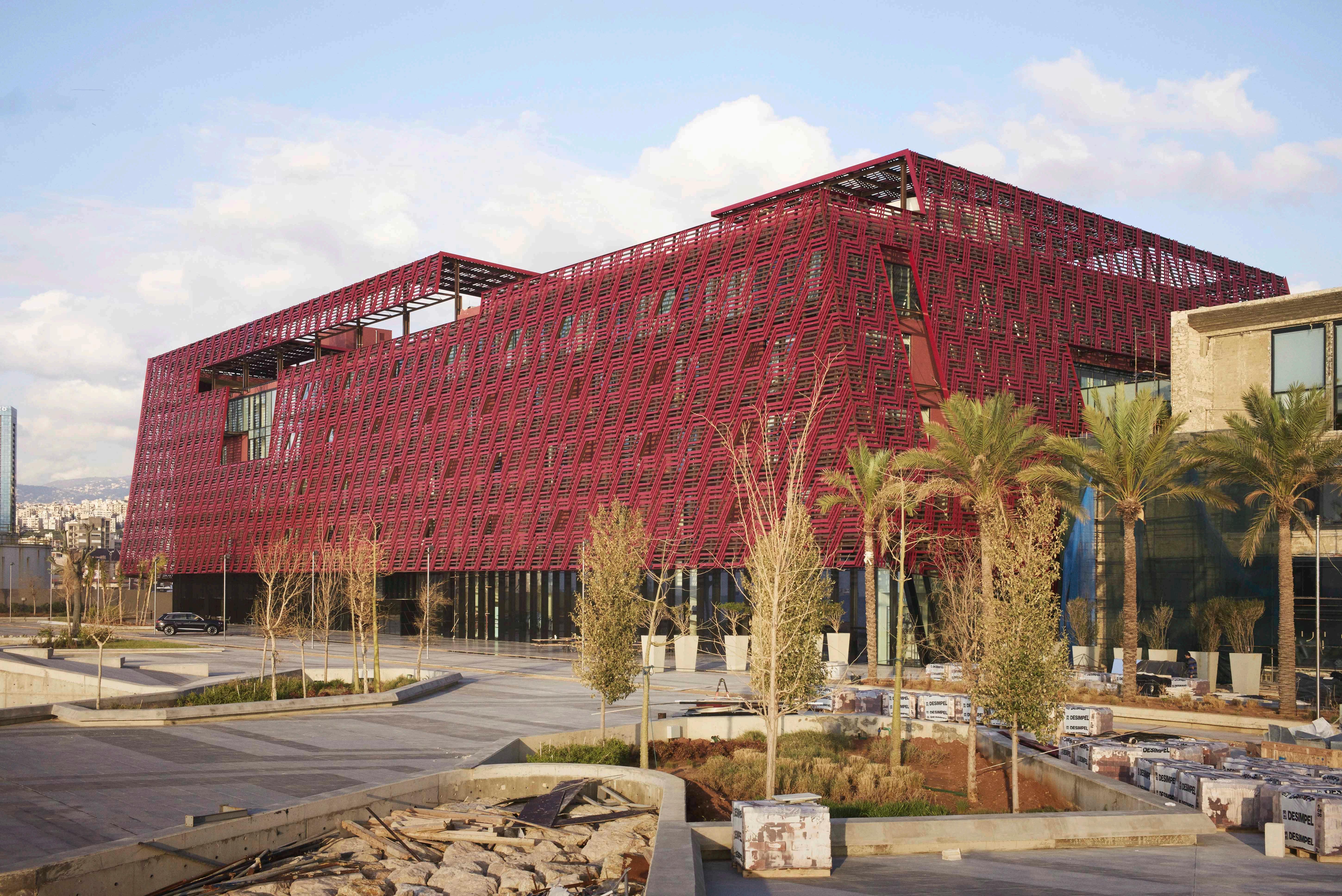
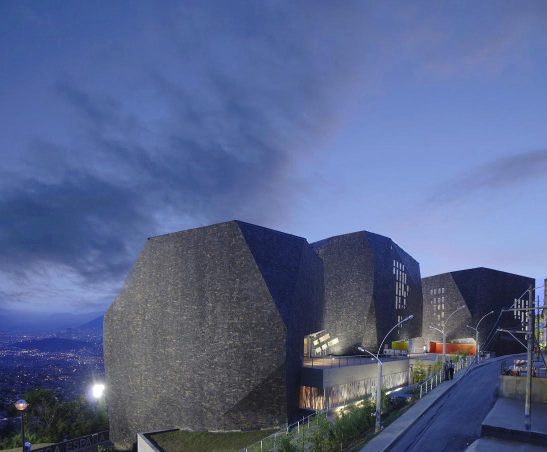
PARQUE ESPAÑA LIBRARY
5..500m2 Cultural Complex, Medellin, Colombia
RIBA Stages 1- 6 (Equivalent) 2008
The Project is located on one of the hillsides that have been affected by the violence since the 80´s because of the drug traffic network that operates in the city of Medellin. It is part of the government’s social master plan program to give equal economic and social opportunities to the population.
The program asked for a building with library, training room, administration room and auditorium on a unique volume. The proposal was to fragment the program in three groups: The library, the rooms, and the auditorium; then join them with a bottom platform that allows flexibility and autonomy, improving the people’s participation considering each volume operates independently.
The city is located in the north of Los Andes mountain ridge, one of the most topographically broken places of Colombia. This geography defines the identity and the image of the city. This image is precisely what the project aims at, it intends to integrate itself into the landscape and become an interpretation of it.. More than a building, it proposes the construction of an operative geography that belongs to the valley like a mechanism of organization of the program and the zone, showing the unknown directions of the irregular mountain contours, not like a metaphor, but like an organization of the form in the place, a folded building cut like the mountains. A landscape building that redefines the folded mountain structure in form and space, nullifying the idea of the landscape like a background and encouraging the ambiguity building-landscape.
54
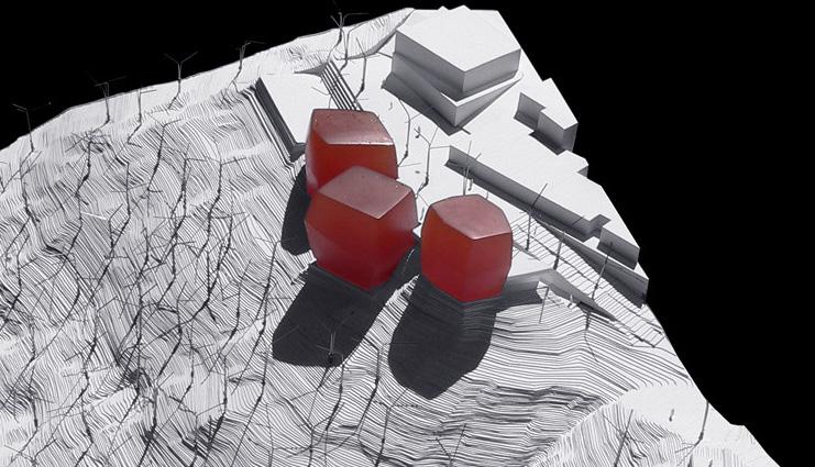
The Project is organized in two structures: the first one is the building - landscape (rocks) and the second one is a platform that integrates and transforms the cover into a square that looks into the valley; this way, the building is empowered as a meeting place, multiplying the connections and letting it develop as a reference point.
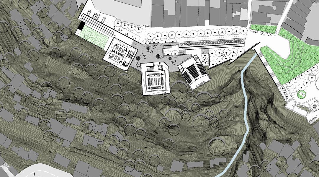
55
Concept Model
Ground Floor Plan
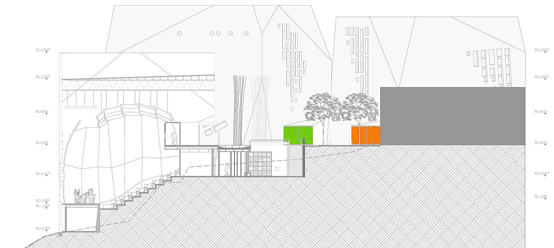
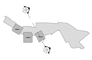
56
Cross Section
Facade Section
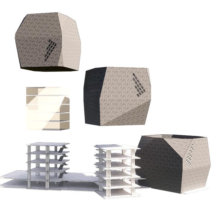
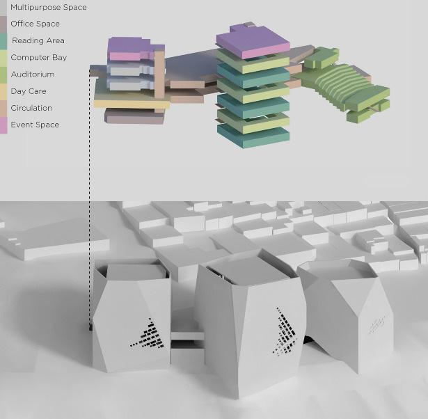
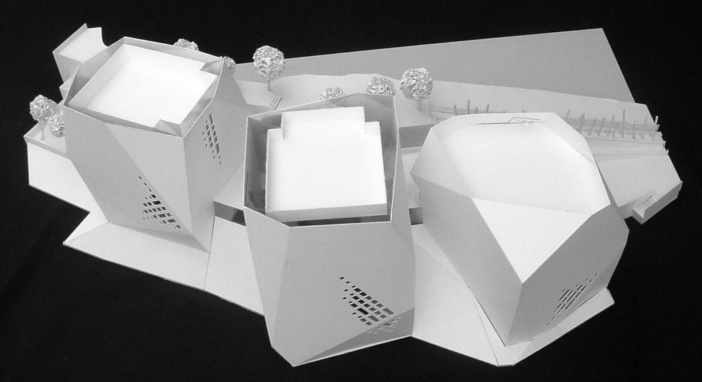
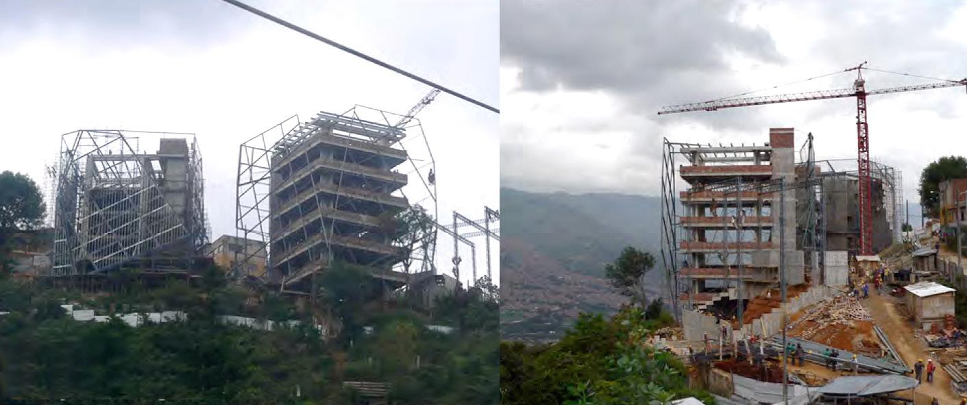
57 Exterior Skin Interior Skin Independent Structure for each Volume
Concept Model
Facade Concept/ Program Axo
Construction process
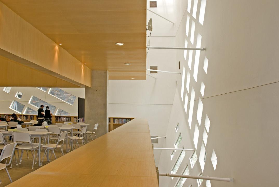
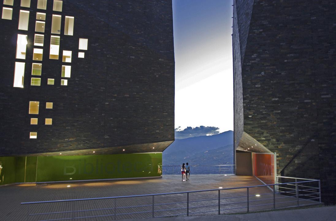
58
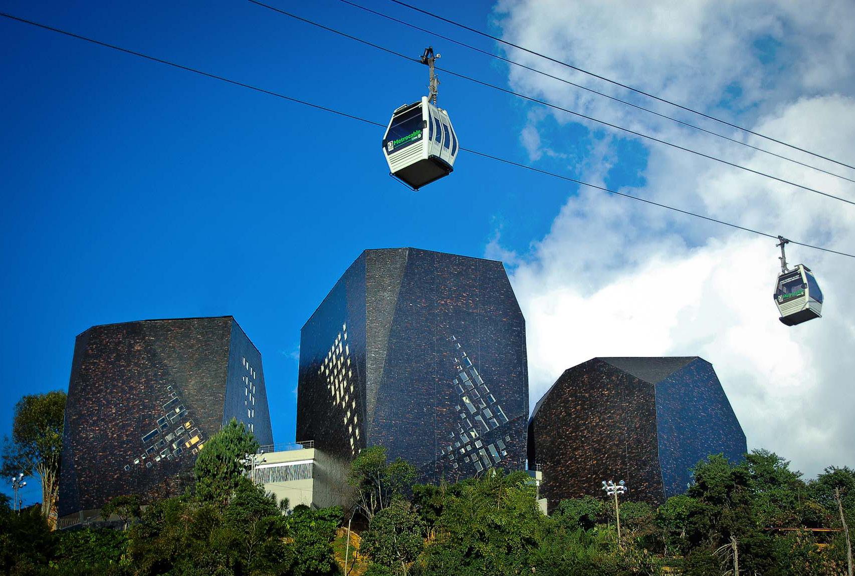
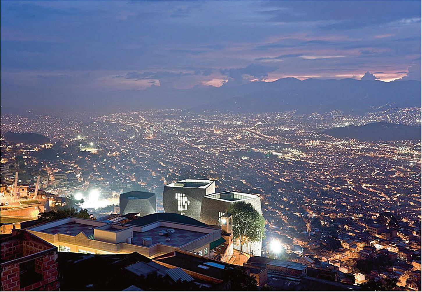
59
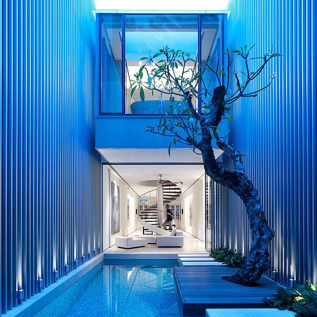
FIFTY FIVE BLAIR ROAD
280m2 Private House
Singapore
RIBA Stages 1- 6 (Equivalent)
2007
The ornate art deco facade of this former shop house gives no clues to the contemporary residence it shelters. Inside, a metallic architectural language unifies the space and conveys a modern flavour. The overall scheme successfully establishes a relationship between inside and outside space and presents a diverse series of spaces suited to a range of activities. A large aluminium-clad airwell divides the two sections of the house, allowing maximum light penetration and encouraging natural ventilation.
The ground floor features flexible glazed walls that lead directly to the central pool, alongside which and old frangipani tree grows through a wooden deck. The main spiral staircase is a rhythmic ribbon that ascends to the attic space and acts as a central pin through the main section of the residence. On the second and third floors, the stairwell is encased in a stainless steel mesh. A cylindrical roof skylight above creates a vertical column of light that can reach the bottom parts of the stairs.
The master bedroom features an ensuite bathroom in the form of a glazed box that cantilevers over the pool area, and a large void that allows views down to the first floor. These modern interventions emphasize the playful nature of the scheme.
60
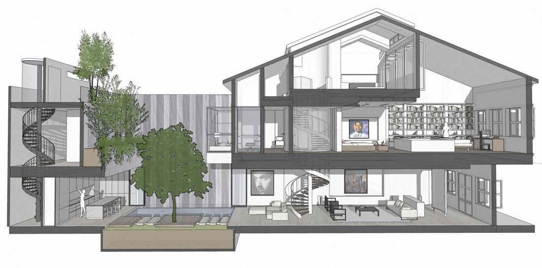
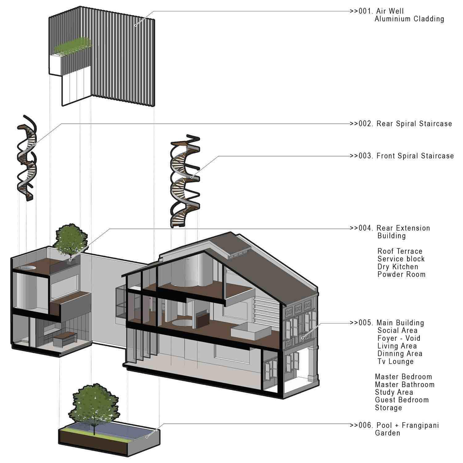
61
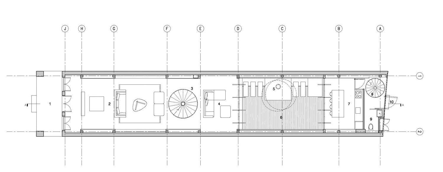
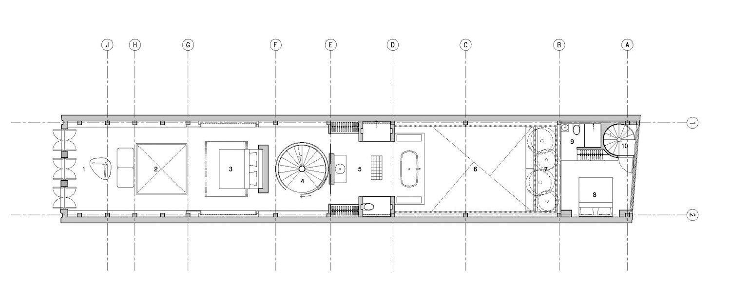
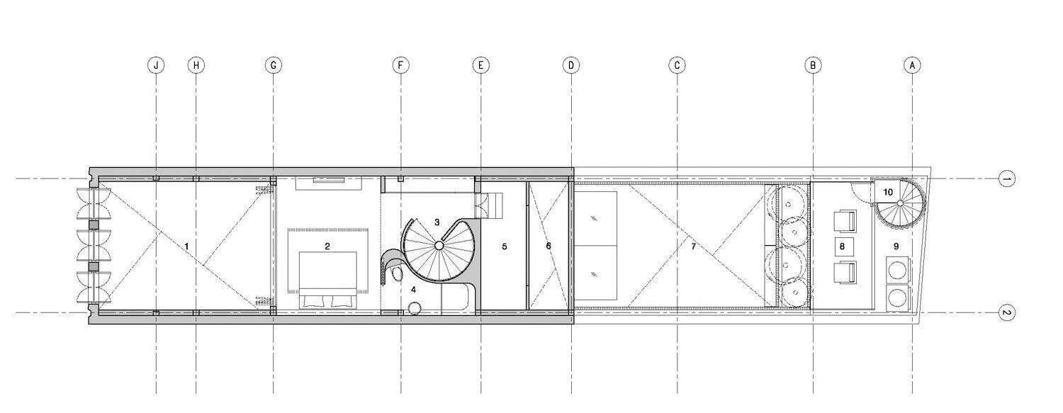
62
Floor
Floor Loft
Ground
First
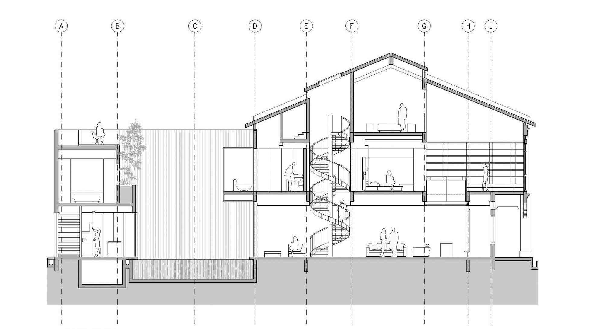
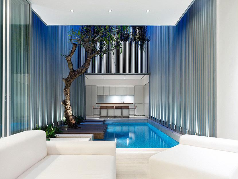
63
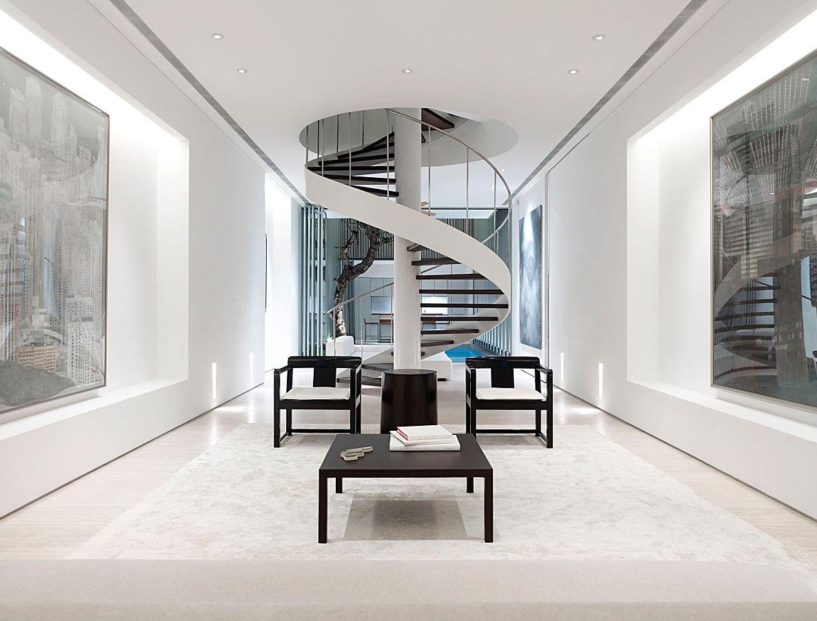
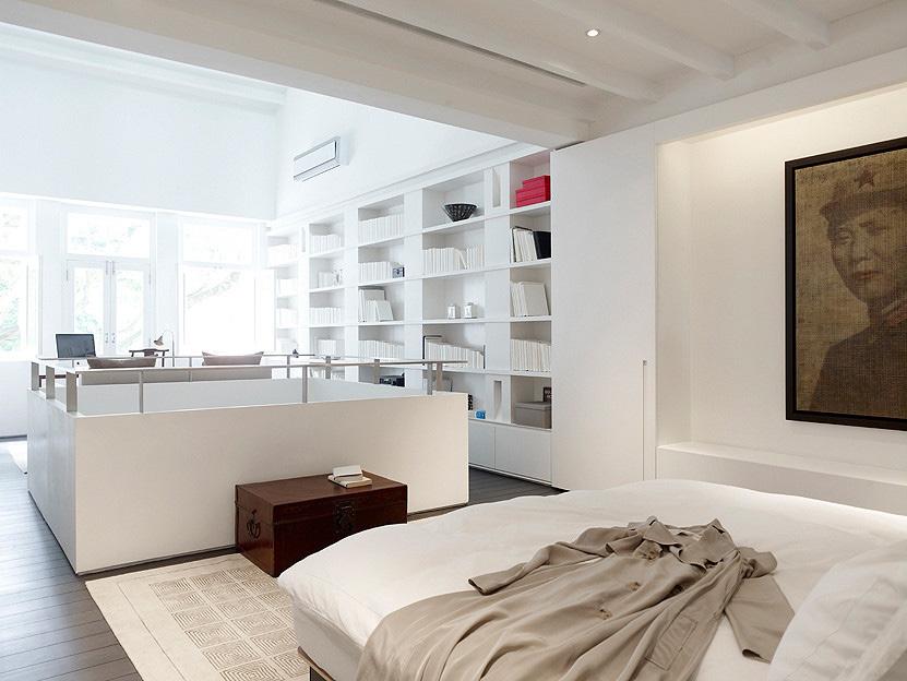
64
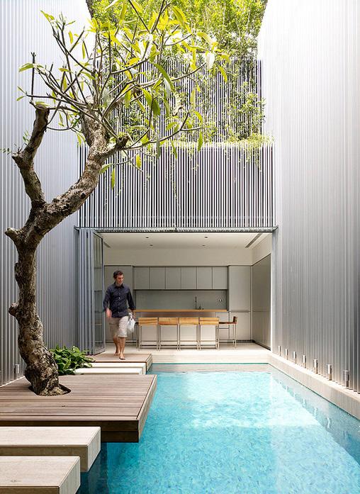
65
OTHER WORKS
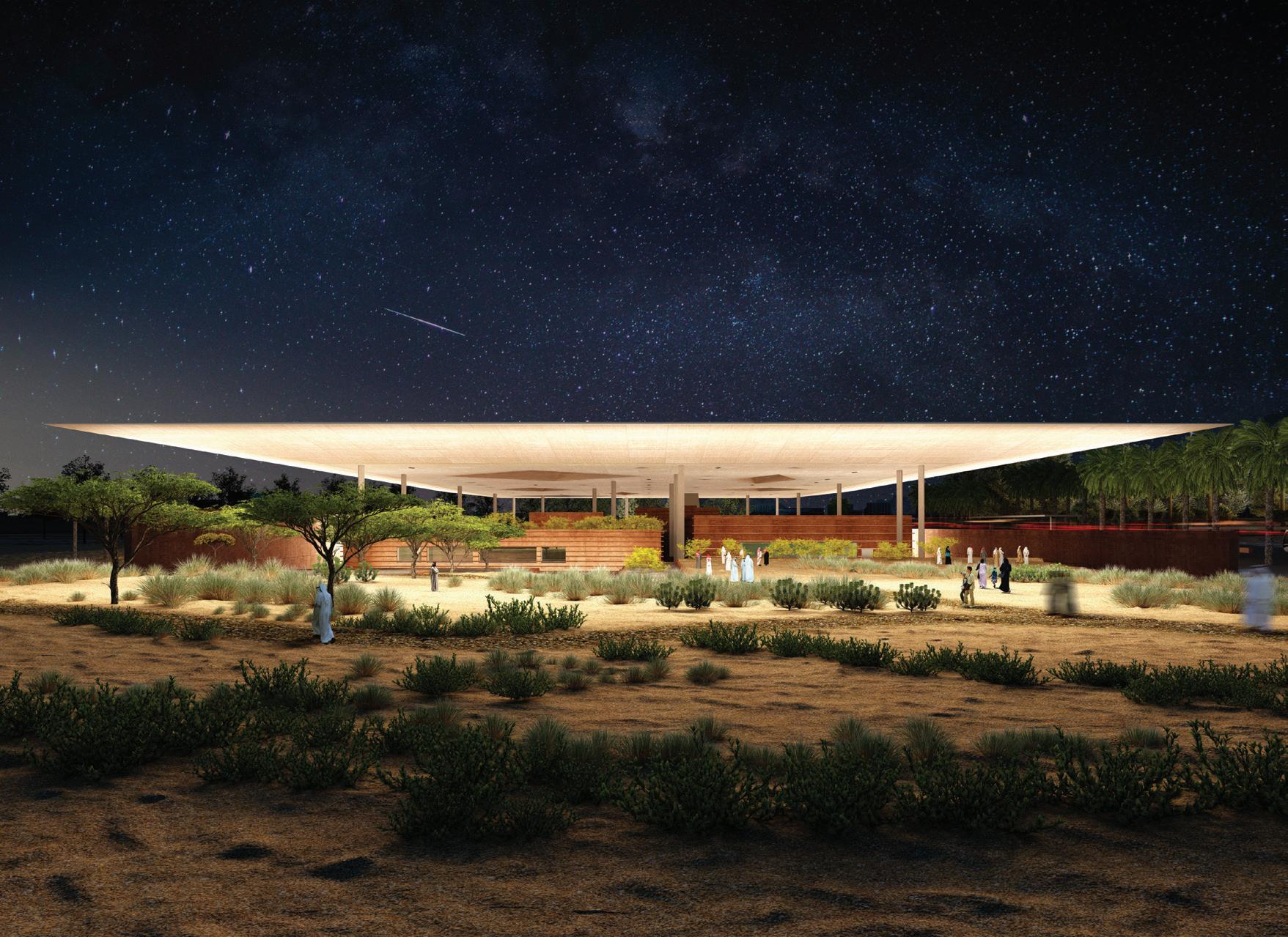
KING SALMAN PARK VISITOR PAVILION
(Competition, Winning Scheme)
7.000m2 Visitor Centre
Riyadh, Saudi Arabia
RIBA Stages 1- 4 (Under Construction)
2018
The Visitors’ Centre and Nursery speak the same distinct language as their contextual surroundings. They seek to act a hospitable, graceful and natural extension to the existing qualities that make Riyadh so texturally and visually rich.
Both the Centre and the Nursery have been conceived as a site for unique symbiosis of nature and the city, desert and oasis. The scheme rises steadily from a sunken cluster of sandy-hued pavilions across to a gradually inclining network of greenery and plant life. It takes its departure point from power of the surrounding wadi, unearthing it and developing into our interpretation of a new chapter to Riyadh’s cultural life.
The juxtaposition between the wadi’s natural state and the ambition for King Salman Park helped form our design response in its totality. Similarly, we looked to the geology and the formation of the limestone Tuwaiq Mountains to inform our design, allowing them to guide our principles for the buildings’ shape and massing. The geology and formation of the limestone Tuwaiq Mountains informed the scheme’s stone pavilions, which rise up from the entire site’s base and carve out into the landscape. The mountains are formidable, natural landmarks that emulate strength and longevity and this concept runs throughout our design, reflecting in the monumentality of our envisioned built Centre.
68

The Visitors’ Centre and Nursery that we have designed speak the same distinct language as their contextual surroundings. They seek to act a hospitable, graceful and natural extension to the existing qualities that make Riyadh so texturally and visually rich. Both the Centre and the Nursery have been conceived as a site for unique symbiosis of nature and the city, desert and oasis. The scheme rises steadily from a sunken cluster of sandy-hued pavilions across to a gradually inclining network of greenery and plant life. It takes its departure point from power of the surrounding wadi, unearthing it and developing into our interpretation of a new chapter to Riyadh’s cultural life. The juxtaposition between the wadi’s natural state and the ambition for King Salman Park helped form our design response in its totality. Similarly, we looked to the geology and the formation of the limestone Tuwaiq Mountains to inform our design, allowing them to guide our principles for the buildings’ shape and massing. The geology and formation of the limestone Tuwaiq Mountains informed the scheme’s stone pavilions, which rise up from the entire site’s base and carve out into the landscape. The mountains are formidable, natural landmarks that emulate strength and longevity and this concept runs throughout our design, reflecting in the monumentality of our envisioned built Centre.
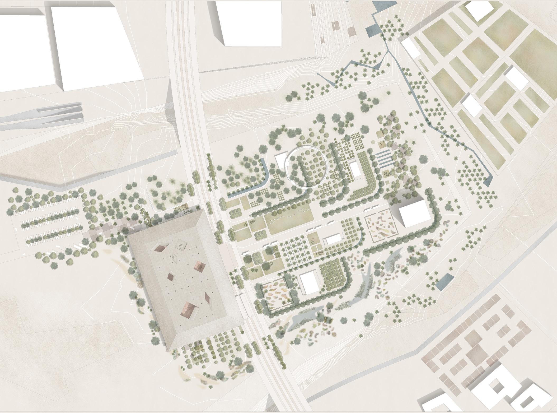
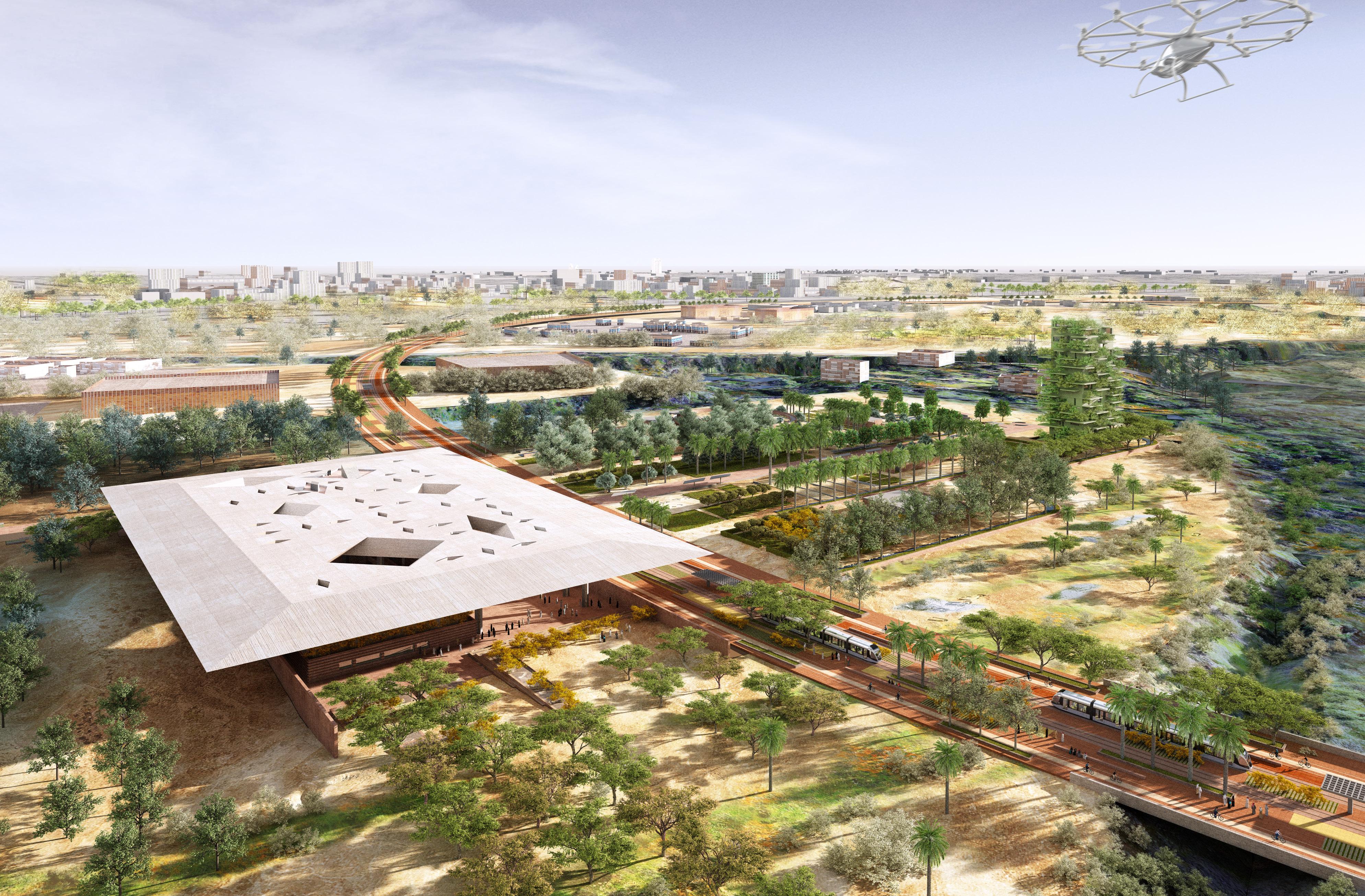
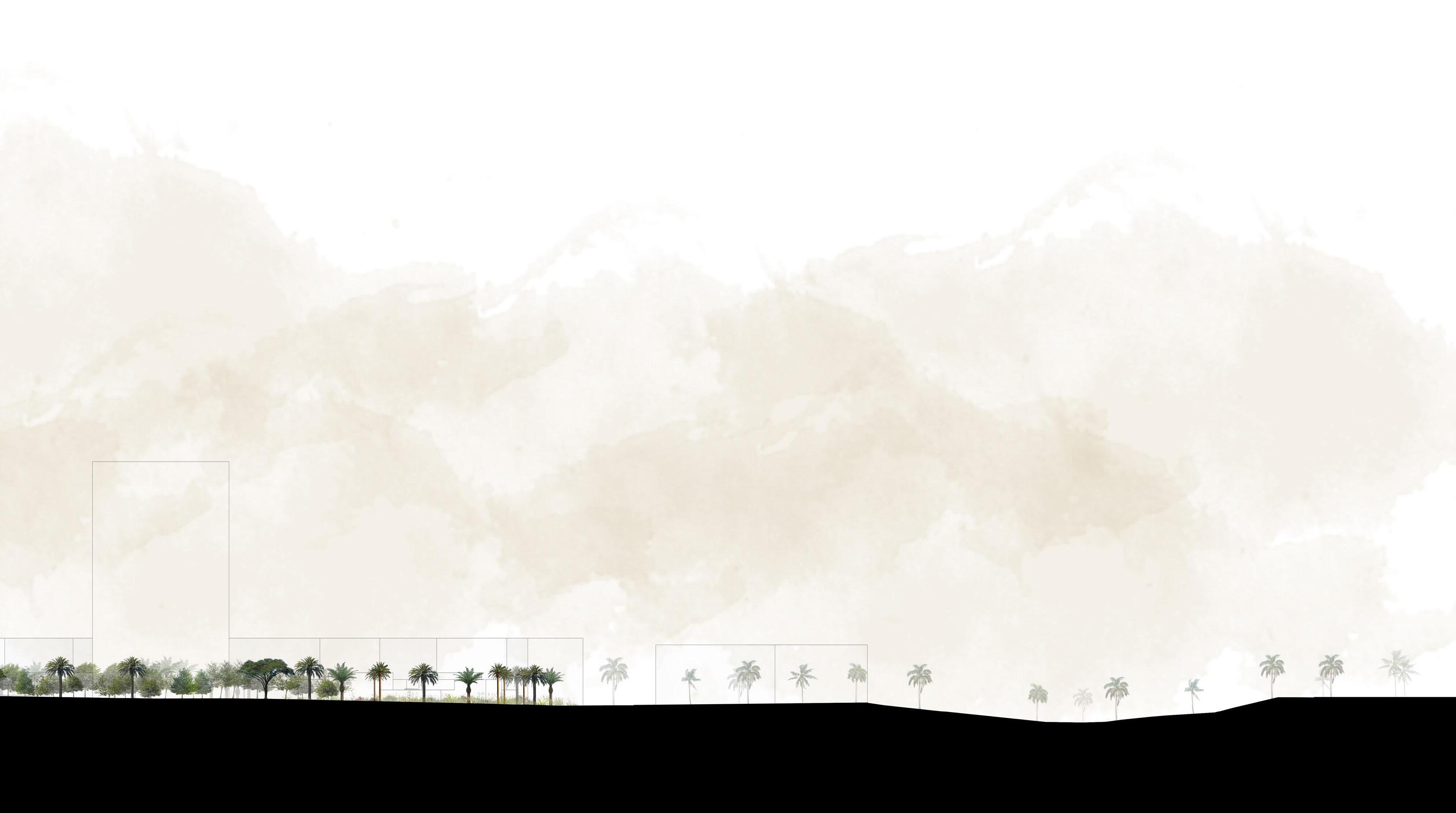

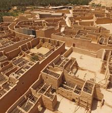
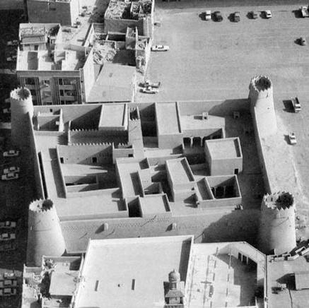
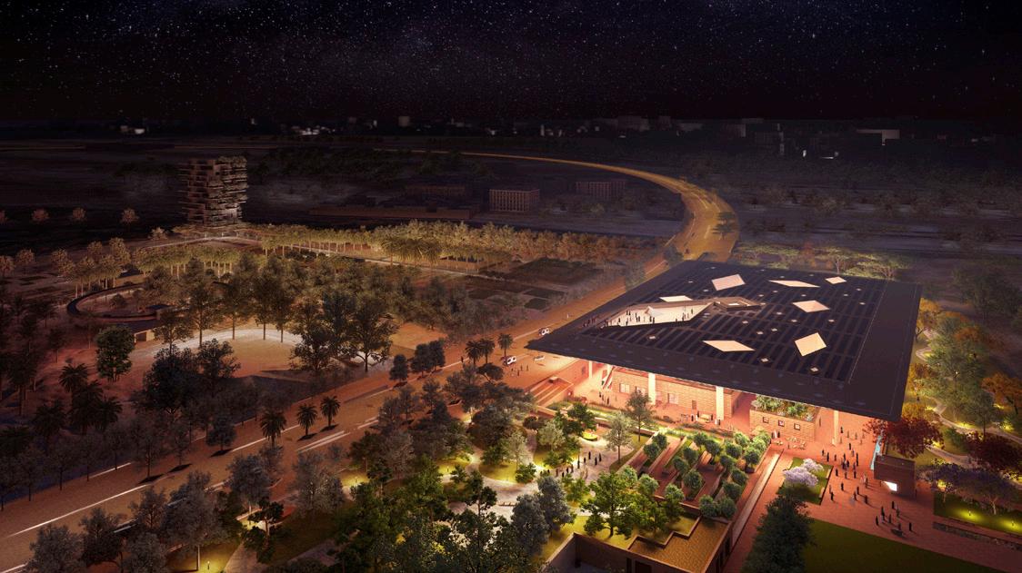
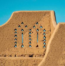
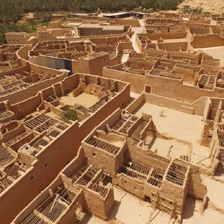
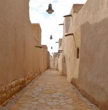
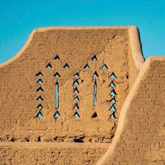


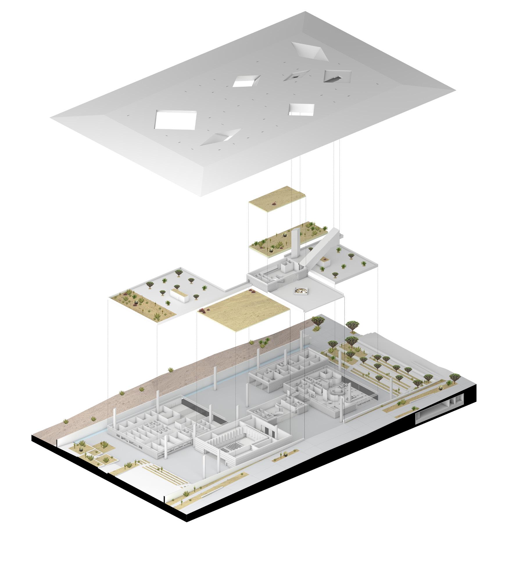
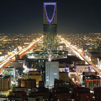
69 7. Retail 8. Administration 9. Plant Rooms 10. VIP Viewing platform 11. Visitors’ Viewing Platform 12. Entrance from Loop 13. Entrance from Parking 14. Auditorium Expansion 15. Cafeteria Terrace 16. Offices Terrace Exploded Axonometric Local Landmarks Timeline 1930’s 1950’s 1970’s 1980 1990’s Qasr alMurabba Built 1936 Riyadh Water Ministry building on King ‘Abd al‘Aziz Street 1860’s Local precedents and historical references Key 1. Entrance Lobby 2. Auditorium 3. Cafeteria 4. BOH 5. Sales and Marketing 6. Exhibition 7. Retail 8. Administration 9. Plant Rooms 10. VIP Viewing platform 11. Visitors’ Viewing Platform 12. Entrance from Loop 13. Entrance from Parking 14. Auditorium Expansion 15. Cafeteria Terrace 16. Offices Terrace Exploded Axonometric of the Visitors Pavilion 14 Local Landmarks Timeline Built 1865 Built 1936 Built 1971 King ‘Abd al‘Aziz Street Built 1987 Kingdom Centre Built 2002 Local precedents and historical references 20 50 100 m 10 0 Key 1. Parking Phase 1 2. Entrance Plaza Phase 1 3. Entrance Plaza Phase 2 4. Pavilion 5. Loop 6. Tram stops 7. Mountain Woodlands 8. Rock Gardens 9. Agricultural Terraces 10. Desert and Dwarf Shrublands 11. Coastal Plains 12. Greenhouses 13. Tree top walk loop 14. Canopies 15. Family Garden 16. Vertical Garden 17. Wadi 18. Plaza 19. Water Feature 20. Meadow Site Plan - scale 1:1500 1 2 4 5 7 9 9 10 10 17 17 10 3 4 5 6 7 8 11 13 12 1 2 4 4 Key 1. Entrance Lobby 2. Auditorium 3. Cafeteria 4. BOH 5. Sales and Marketing 6. Exhibition 7. Retail 8. Administration 9. Plant Rooms 10. VIP Viewing platform 11. Visitors’ Viewing Platform 12. Entrance from Loop 13. Entrance from Parking 14. Auditorium Expansion 15. Cafeteria Terrace 16. Offices Terrace
Aerial view of the Visitors’ Centre: Daytime Exploded Axonometric Proposed masterplan with assets Landmark Local Assets 1. Visitor Nursery and Pavilion 2. Royal Arts Complex 3. Water Park 4. Parking Mountain 5. Sport Pitch Tower 6. Aviation Museum 7. Edible Garden 8. Main Asset 9. Viewing Ramp 10. Conference & Exhibition Centre 11. Jumaa Mosque 12. Souk 13. Riyadh Cultural District 14. Planetarium The proposed site sits on top of the loop creating the opportunity to design a landmark building that can be seen from far across the master plan and from the air Connectivity Functional Nodes Natural Attraction Key Key Key Key Main Roads Religious buildings Landmarks Metro Line Universities Historical monuments Train Station Museums Park Bus Station Libraries Nursery plants Airport Government buildings Wadi Local Landmarks Timeline 0 100 200 500 m al-Masmak Fortress Built 1865 1930’s 1950’s 1970’s 1980 1990’s 2000’s Qasr alMurabba Built 1936 Riyadh Water Tower Built 1971 Ministry building on King ‘Abd al‘Aziz Street 2020’s King Fahd Stadium Built 1987 Ministry of Interior Built 1989 Faisaliah Tower Built 2000 Kingdom Centre Built 2002 King Salman Park Visitors Pavilion and Nursery 1860’s Local precedents and historical references
Local Precedents and Historical References
Initial Sketch of the Visitor Pavilion by Sir David Adjaye
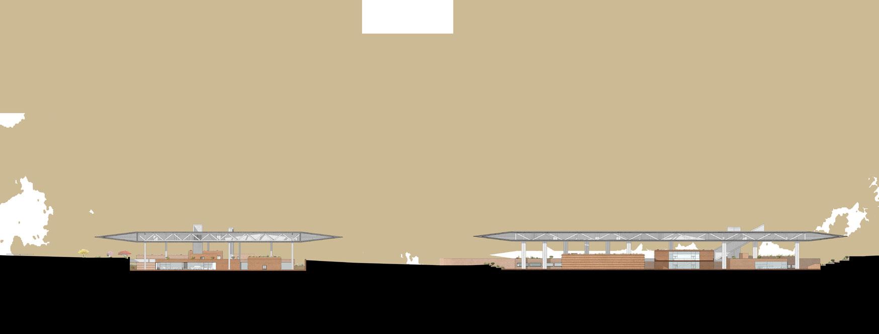
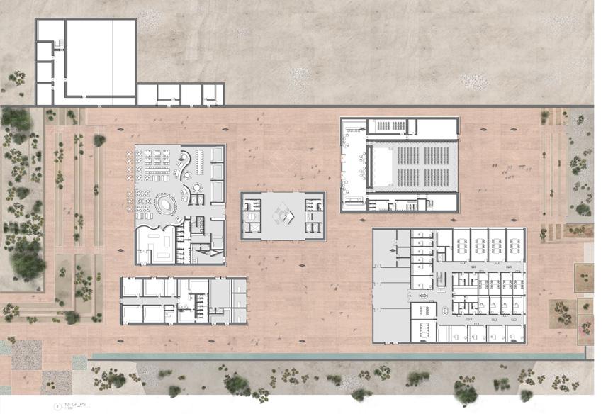
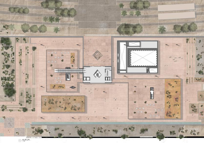
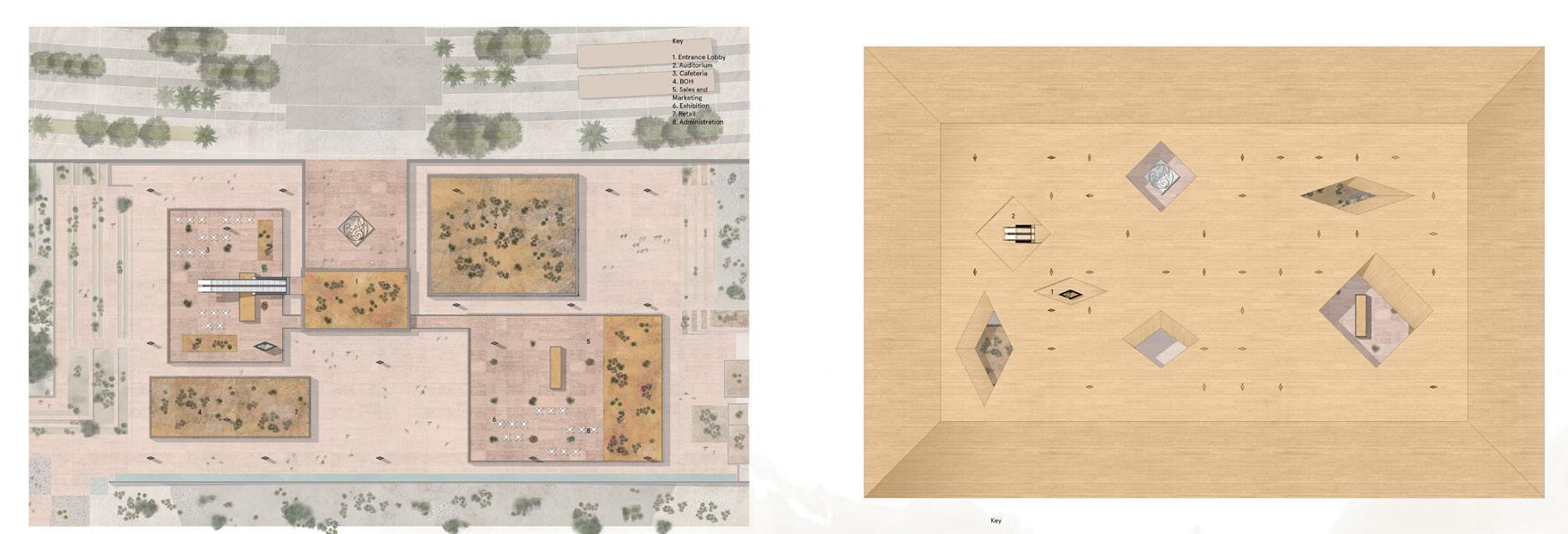
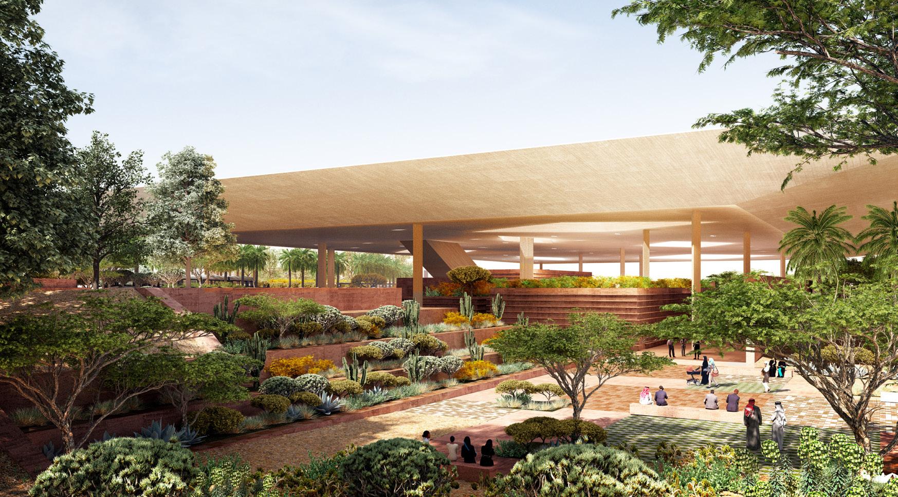
70 Long Elevation - East Long Elevation North Key 1. Entrance Lobby 3. Cafeteria 4. BOH 5. Sales and Marketing 6. Exhibition 7. Retail 9. Escalator to Viewing Platform 10. Lift to VIP Viewing Platform Visitors’ arrival through the Entrance Pavilion (Phase & II) to the public viewing platform Executive arrival through the Business, Admin and Exhibition Pavilion to the roof terrace VIP arrival through the VIP dedicated entrance and lift in the Cafeteria Pavilion to the private VIP viewing platform We’ve designed a Centre that is as cohesive as it is multifunctional. It welcomes its disparate groups of users — visitors, services, staff, executives and VIPs — in different, yet consistently considered, ways. Visitors enter through the two main entry points at the eastern and western sides of the Centre, traversing lengthways across the site from north to south as they discover the various offerings within the wide-ranging spaces. Service vehicles meanwhile cross the site from west to east, at right angles to the pedestrian flow, being able to drive into the western entry courtyard without impediment no matter their vehicular size. Members of staff also enter from the west, approaching the centre from the car park. With staff facilities being positioned at the area of the site closest to that specific entry point, they are able to reach their workplace with added privacy and ease. A private VIP route has been designed in a distinct way so as to offer a premium entrance experience without sacrificing the cohesiveness of the Centre’s design. VIP visitors enter through a private lift which transports them directly to a designated lobby and viewing platform on the roof. As with all other terraces within the Centre, they will be able to enjoy semi-hard landscaping and individual planted roof gardens that at once incorporate the lushness of the external landscape whilst enjoying shade from the large roof above. These green terraces will be accessible via staircases and escalators and connected to one another via elevated bridge walkways that unite the Centre’s three central pavilions. Separate to the VIP viewing platform, a public visitors’ viewing platform will be accessible from the main entrance pavilion via a covered escalator. All the Visitors’ Centre’s guests will therefore have access to varied rooftop terraces, providing them with the best views across the Nursery and the masterplan beyond. 6 4 Long Elevation - East Long Elevation North Key 1. Entrance Lobby 2. Auditorium 3. Cafeteria Marketing 6. Exhibition 9. Plant Rooms Key 1. Entrance Lobby 2. Auditorium 3. Cafeteria Marketing 6. Exhibition 9. Escalator to Viewing Platform 10. Lift to VIP Viewing Platform View looking towards the Visitor Pavilion from the southerly desert landscape Lower Ground Floor Plan: Courtyard Level Upper Ground Floor Plan: Entrance Level VIP arrival through the VIP dedicated entrance and lift in the Cafeteria Pavilion to the private VIP viewing platform 3 5 8 6 9 5 6 Competition Scheme


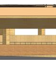
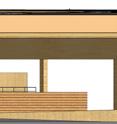
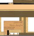
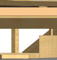
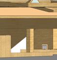
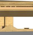
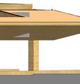
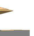


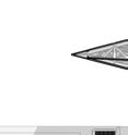
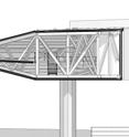

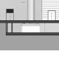


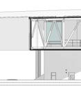
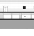
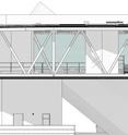
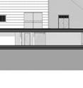
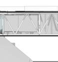
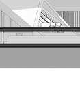
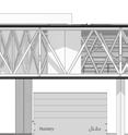
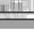
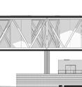
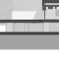
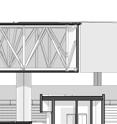
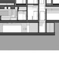
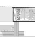
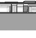
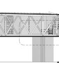

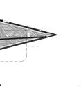
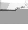

71 H K L M N P Q R S G F E D 5 6 7 9 10 11 C B T U 3 13 14 A 2 1 10000 10000 10000 10000 10000 10000 10000 10000 10000 10000 10000 10000 10000 SINGLE PLY VENTILATION VENTILATION VOID 1:4 1000 1000 90° 90° AREAS FRONT OF HOUSE Contractor to check all dimensions on site. Adjaye Associates to be advised of any discrepancies between this drawing and site conditions immediately.Sky Pavilion Floor Plan King Salman Park Visitors Pavilion KSP Foundation 1:200 @ A0 Sky Pavilion Floor Plan P0.024/02/20CC 50% P2.117/08/20DD 50% P3.028/09/20DD 100% H K L M N P Q R S G F E D C B Lower Ground Floor 4000 specification and all relevant drawings. Do not scale from this drawing. Adjaye Associates to be advised of anyAdjaye Associates Key Plan Lower Ground Floor - - - - - - -Exterior Elevations 2 P2.015/06/20SD 100% P2.117/08/20DD 50% H J K L M N P Q R S G F D T U 8450 4000 3270 AREA OF MOCK UP 6000 H J K M N P Q R S G F E D C B T A H J K L M N P Q R S G F E D C B T U A Long Section CC' through Auditorium and Dining Pavilions Contractor to check all dimensions on site. Adjaye Associates to be advised of any discrepancies between this drawing and site conditions immediately.Adjaye Associates Key Plan Lower Ground Floor P5.0 KSP-AAL-P1-CD-VP-DWG-ARC-13-100 Building Sections King Salman Park Visitors Pavilion 100% Construction Documents KSP Foundation 1:200 @ A0 P0.024/02/20CC 50% P3.028/09/20DD 100% P4.016/11/20CD 50% D C Underside the Roof STAINLESS STEEL GRILLE AND TRAP MESH GUTTER RWP -REFER TO MEP DRAWINGS 3000 1100 1100 30MM DRIP GAP 550 3000 6000 1 30MM DRIP GAP CON-101 BAL-401 CONC-215 5 4 COPPER STRIKE PAD FOR EARTHING REFER TO MEP DRAWINGS 75 CON-101 General Notes: Adjaye Associates to be advised of any discrepancies between this drawing and site conditions immediately. P2.1 100% Construction Documents Roof Cantilever Detail -Section AA' 1 Key Plan AA' P0.015/06/20SD 100% P1.017/08/20DD 50% P2.016/11/20CD 50% P2.121/12/20CD 100% Stage 4 Drawing Packages H J K L M N P Q R S G F E D 5 6 7 9 10 11 C B T U 3 13 14 A 2 1 10000 10000 10000 10000 10000 10000 10000 10000 10000 10000 10000 10000 10000 130000 SINGLE PLY VENTILATION VENTILATION VOID 1:4 1000 90 1000 90° 90° AREAS FRONT OF HOUSE Contractor to check all dimensions on site. Adjaye Associates to be advised of any discrepancies between this drawing and site conditions immediately.Adjaye Associates - - - - - - -Sky Pavilion Floor Plan King Salman Park Visitors Pavilion KSP Foundation 1:200 @ A0 Sky Pavilion Floor Plan P0.024/02/20CC 50% P2.117/08/20DD 50% P3.028/09/20DD 100% H J K L M N P Q R S G F D C T U A 8450 4000 3270 AREA OF MOCK UP 6000 H J K M N P Q R S G F E D C B T U A H J K M N P Q R S G F E D C B T U A Long Section CC' through Auditorium and Dining Pavilions Contractor to check all dimensions on site. Adjaye Associates to be advised of any discrepancies between this drawing and site conditions immediately.Adjaye Associates Key Plan Lower Ground Floor P5.0 KSP-AAL-P1-CD-VP-DWG-ARC-13-100 Building Sections King Salman Park Visitors Pavilion 100% Construction Documents KSP Foundation 1:200 @ A0 P0.024/02/20CC 50% P3.028/09/20DD 100% P4.016/11/20CD 50% H K L M N P Q R S G F E D C B U Lower Ground Floor H J K M N P Q R S G E D C B T U Roof Top Low point 6000 8450 4000 specification and all relevant drawings. Do not scale from this drawing. Adjaye Associates to be advised anyAdjaye Associates Key Plan Lower Ground Floor - - - - - -Exterior Elevations East Elevation (loop) 1 2 P2.015/06/20SD 100% P2.117/08/20DD 50%
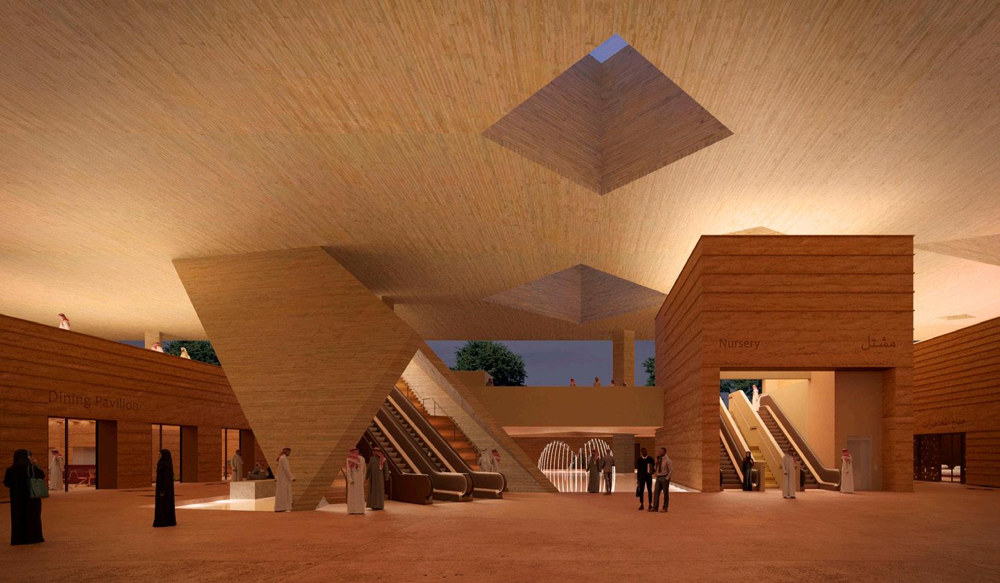
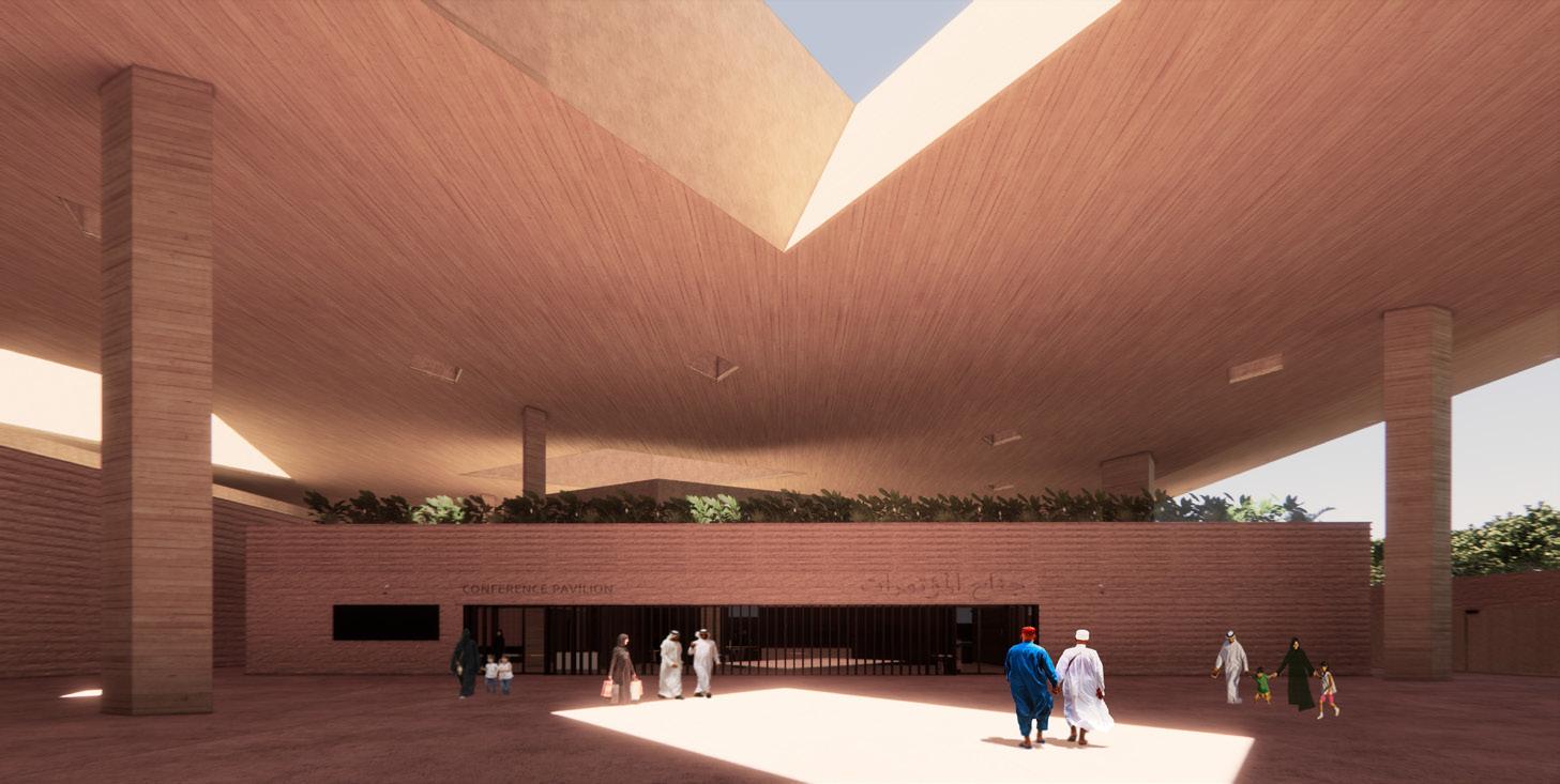
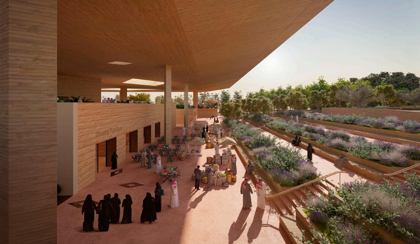
72
73 Interior Exterior ALUMINIUM. WPS-112 EPDM ANODISED JAMB PLATE KSP-PFE-P1-VPN-CD-AR-DWG-0042 FINGER TRAP 3200 1950 FL-102 CAST IRON CLAY MORTAR JOINT AND BAC-101 MASONRY GALVANISED STEEL BAC-101 MASONRY WALL REINFORCEMENT- -755 150 120 INSULATION DiningWellness, Dining611.953 Labyrinth FL-102 BRONZE ANODISED CAST IRON ENTRANCE CONCRETE FINISH –ROUGH CON-103 PIGMENTED Refer to external door detail drawings: KSP-PFE-P1-VPN-CD-AR-DWG-0042 KSP-PFE-P1-VPN-CD-AR-DWG-0043 ANODISED JAMB PLATE 1208 360 1100 4040 333 BAC-101 REINFORCEMENT STRUCTURAL CALCULATIONS. WATERPROOFING MEMBRANE BRICKWORK COPING, MATCHING SGN-311 EMBOSSED- -BLK-01C DOUBLE SOLID BLOCKWORK WPS-121 COLD APPLIED BITUMINOUS INSULATION VAPOUR Dining600 Labyrinth Wellness, Dining611.953 50 3155- --- -3200- -300 600 375 600 675 Refer to external door detail drawings: KSP-PFE-P1-VPN-CD-AR-DWG-0041 3500 50 450 50 450 50 450 50 450 50 1450 50 450 50 450 50 450 50 450 50 450 50 600 55 500 AM-105 8MMBRONZE ANODISED JAMB SHADOW GAP AM-105 8MM BRONZE ANODISED 20MM SHADOW GAP COPING, MATCHING RAMMED EARTH TONE 600X50X600MM BRICKWORK –NOTCHED BRICK BANDING MATCHING RAMMED 1950 SIGNAGE (50MM). REFER TO WAYFINDING AND SIGNAGE1,2 & Dining - Roof LevelCON-102 CONCRETE FINISH BAC-101 REINFORCEMENT ROD AND GALVANISED CALCULATIONS. 75 WATERTIGHT SEAL (COMPOUND RUBBER AND BITUMEN JOINT CON-102 CONCRETE FINISHPIGMENTED AND BUSH HAMMERED SINGLE PIGMENTED AND BUSH HAMMERED CON-102 PIGMENTED AND CON-103 PIGMENTED AND SMOOTH CONCRETERECESSED HANDRAIL CONCRETE STAIRCASE. SANDBLASTED ). PT-135 WATER Wall mounted speaker CM-FR-01Info kiosk external microphoneHydrant cabinetspecification and all relevant drawings. Do not scale from this drawing. Adjaye Associates to be advised discrepancies between this drawing conditions immediately. Key Plan Lower Ground Floor 2 1 Dining Pavilion Key Plan 5 P1.017/08/20DD 50% P1.128/09/20DD 100% P2.016/11/20CD 50% P2.121/12/20CD 100% H G F E D 10 11 Electrical Riser Waste Room Lobby Dry Store FFL 611.953 M Toilet Staff Lounge- -- -- -- -- -- -- -- -- -- -- -- -- -- -- -- -- -- -- -- -- -- -- -- -- -- -- -- -- -- -- -- -- -- -- -- -- -- -- -- -- -- -- -2010 3060 2010 Void above eG4 eG4 260- -4660 4680 1240 970 1520 1550 1050 360 1100 1210 SSL 611.653 F1 F2 PA W3 LED projector mounted on louvres for glare, 200W LED projector mounted on louvres for glare, 130W LED projector mounted on Recessed LED inground, 10W15deg), 2.7W Flexible ledstrip mounted in 8m pole with street cast concrete, 12W Drawn By: General Notes: specification and all relevant drawings. Do not scale from this drawing. Contractor to check all dimensions on site. conditions immediately.Adjaye Associates P2.0 As indicated @ A0 CG - - - - - - -Wellness Lower Ground Floor Plan _ GA Setting Out King Salman Park Visitors Pavilion 100% Construction Documents Key Plan N 1 P0.017/08/20DD 50% P1.116/11/20CD 50% 12 Interior Exterior-755 RAMMED EARTH Refer to external windows detail drawings: KSP-PFE-P1-VPN-CD-AR-DWG-0012 KSP-PFE-P1-VPN-CD-AR-DWG-0013 WALL REINFORCEMENT AS PER STRUCTURAL CALCULATIONS STEEL ANCHOR AND MASONRY WALL REINFORCEMENT AS PER 180 1340 180 Interior Exterior 2900 570 350 BLK_04 BARRIER drawings: KSP-PFE-P1-VPN-CD-AR-DWG-0011 KSP-PFE-P1-VPN-CD-AR-DWG-0013 KSP-PFE-P1-VPN-CD-AR-DWG-0014 BRICKWORK COPING, MATCHING RAMMED EARTH TONE 740X50X600MM ENGINEER DRAWINGS WATERPROOFING REFER TO THE BRK-01 CLAY FACING BRICKWORK –NOTCHED EARTH TONE 230X50X600MM SSL 616.020CON-105 PIGMENTED 650 CON-102 PIGMENTED INSULATION (THERMAL BRIDGE MITIGATION) INS-102 100MM BATT INSULATION EWS-10 GLASS FIBER REINFORCED CEMENT CLADDING SYSTEM, MATCHING INSITU PIGMENTED CONCRETE EXT-306 PRECAST CONCRETESFS-101 LIGHT STEEL FRAMING SYSTEM WPS-121 COLD APPLIED BITUMINOUS INSULATION 365 10 R2500 REINFORCED CEMENT (GFRC) PANEL CLADDING SYSTEM, AM-111 ALUMINIUM INS-102 100MM BATT INSULATION (THERMAL BRIDGE MITIGATION) BRICKWORK COPING, MATCHING RAMMED FLASHING. BRONZE ANODISED CON-103 PIGMENTED 600 1300150 ENGINEER DRAWINGS BARRIER TRASS LIME INS-306 THERMOBLOCK MINIMUM CAVITY FOR THE INSTALLATION OF THE COPING, MATCHING RAMMED EARTH TONE 740X50X600MM INS-102 100 MM BATT INSULATION (THERMAL BRIDGE MITIGATION) 600 SMOOTH CONCRETE FINISH (WAFFLE SLAB) BAC-101 MASONRY GALVANISED STEEL ANCHOR AND MASONRY INS-102 100 MM BATT INSULATION (THERMAL BRIDGE MITIGATION) SHEET WATERPROOFING EXTW-07 DRAINAGE BOARD EXTW-07 WPS-103 SELF ADHERING BITUMINOUS SHEET WATERPROOFING NOTCHED BRICK BANDING MATCHING RAMMED EARTH TONE 230X50X600MM BLOCKWORK COMPRESSION FILLER BOTTOM WPS-103 SELF DRAINAGE AS PER DRAWINGS-1700 950 4350 600 1700 300 50 200 50 200 50 200 50 200 50 200 50 200 50 200 50 200 50 200 50 200 50 200 50 200 50 200 50 200 50 200 50 200 50 200 50 200 50 200 50 200 50 200 50 350 50 1350 950 BRK-02 CLAY FACING BRICKWORK COPING, MATCHING RAMMED E Exterior 3 CONCRETE FRAMING (REFER TO THE STRUCTURAL DRAWINGS)- -KSP-PFE-P1-VPN-CD-AR-DWG-0032 STRUCTURAL CALCULATIONS STRUCTURAL CALCULATIONS BRICK BANDING MATCHING Wellness - Roof Level - Lower Ground Floor Interior 450SIGNAGE (50MM). REFER TO WAYFINDING AND SIGNAGE CONSULTANTS' DRAWINGS. BRICKWORK –NOTCHED BRICK BANDING MATCHING GALVANISED STEEL ANCHOR AND MASONRY WALL EARTH BOTTOM. 3025 760 1115POLYETHYLENE SHEET WATERPROOFING INS-311 200MM BOARD SUBBASE AS PER STRUCTURAL ENGINEER'S INS-306 E Wellness - Roof Level Wellness, Dining - Lower Ground Floor- -2450 2650 50 350 50 350 50 1150 50 350 50 350 50 350 50 350 50 350 50 350 50 595 50 SIGNAGE (50MM). REFER TO WAYFINDING DRAWINGS. 400 COPING, MATCHING RAMMED EARTH TONE 740X50X600MM FACING BRICKWORK MATCHING RAMMED EARTH TONE 175 140 AM-105 8MM BRONZE SHADOW GAP 2010HEAD + 20MM SHADOW GAP 1, 3 4 5, 6--HYDrawing Title: Drawing specification Do not Contractor Adjaye discrepancies conditions -231 Old Adjaye Key Plan As KSP-AAL External Wellness King Salman 100% KSP Foundation 41-120 -Conference Pavilion -Typical Window -Detail Plan 7 Conference Pavilion -Typical Window -Detail Section 5 8 41-120 -Conference Pavilion -West Façade -Exhibition Space -Detail Section 4 Conference Pavilion -Typical Window -Detail Elevation 6 41-130 -Wellness Pavilion -Typical Detail Plan 2 41-130 -Wellness Pavilion -Typical Detail Section 3 1 Wellness Pavilion Key Plan 9 Conference Pavilion Key Plan 10 P0.018/05/20SDP1.015/06/20SD P1.117/08/20DD P2.028/09/20DD P3.021/12/20CDVOID INSULATION (THERMAL BRIDGE MITIGATION) BRK-02 CLAY FACING BRICKWORK COPING, 250X50X600MM AM-111 ALUMINIUM FLASHING. BRONZE AND SMOOTH CONCRETE FINISH 600 Auditorium, ConferenceSUBBASE AS PER STRUCTURAL BRK-02 CLAY FACING BRICKWORK COPING, MATCHING RAMMED (THERMAL BRIDGE MITIGATION) CON-103 PIGMENTED AND SMOOTH CONCRETE FINISH (WAFFLE SLAB) BAC-101 MASONRY GALVANISED STRUCTURAL CALCULATIONS INSULATION (THERMAL BRIDGE MITIGATION) WPS-103 ADHERING BITUMINOUS EXTW-07 DRAINAGE EXTW-07 GEOTEXTILE WPS-103 SELF ADHERING BRK-01 CLAY FACING BRICKWORK NOTCHED BRICK BANDING MATCHING BLK-01C 200MM SOLID BLOCKWORK 200 EXJ-111 MOVEMENT JOINT 80MM STABILISED RAMMED EARTH DRAINAGE FOUNDATION. REFER TO THE STRUCTURAL E Exterior (REFER TO THE STRUCTURAL DRAWINGS)- -Fitness Studio Reception Refer to external door detail drawings: KSP-PFE-P1-VPN-CD-AR-DWG-0031 BAC-101 MASONRY GALVANISED STEEL ANCHOR AS PER REINFORCEMENT AS PER STRUCTURAL CALCULATIONS BRK-01 CLAY FACING BRICKWORK –NOTCHED 230X50X600MMWellness, Dining0.5% Interior 450SGN-311 SIGNAGE (50MM). REFER TO BRK-01 CLAY FACING RAMMED EARTH TONE 230X50X600MM BAC-101 MASONRY GALVANISED STEEL ANCHOR STRUCTURAL CALCULATIONS 80mm STABILISED RAMMED EARTH BOTTOM. 3025 760 1115 WPS-102 SELF ADHERING POLYETHYLENE SHEETE Wellness - Roof Level Wellness, Dining41-120- -600 2450 2650 300 SGN-311 EMBOSSED SIGNAGE (50MM). CONSULTANTS' DRAWINGS. 400 BRK-02 CLAY FACING BRICKWORK BRK-01 CLAY FACING BANDING MATCHING RAMMED 140 AM-105 8MM 20MM SHADOW GAPBRONZE ANODISED HEAD 20MM 41-120 -Conference Pavilion -Rooftop Core and Large 8 41-120 -Conference Pavilion -West Façade 4 2 41-130 -Wellness Pavilion -Typical Detail Section 3 41-130 -Wellness Pavilion -Typical Detail Elevation 1 Stage 4 Drawing Packages
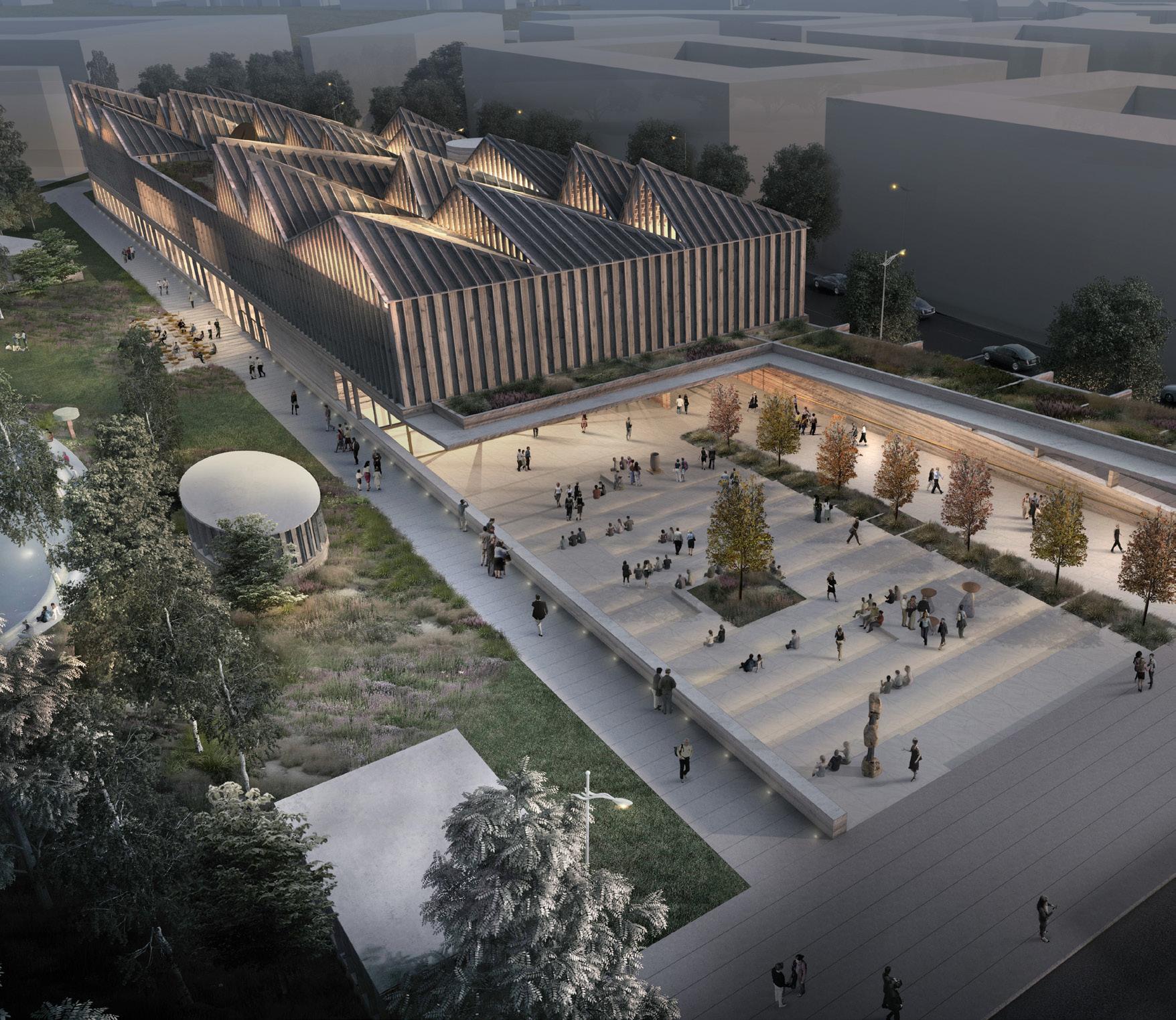
LATVIAN MUSEUM OF CONTEMPORARY ART
(Competition, Winning Scheme)
7.000m2 Art Museum, Riga, Latvia
RIBA Stages 1- 4 ( Suspended ) 2017
The Latvian Museum for Contemporary Art will offer an experience of contemporary art that synthesises art practice and art perception. Speaking to a wide spectrum of artwork, the building comprises a group of flexible spaces for a multinodal display sequence – offering smaller spaces for intimate works through to more expansive environments to facilitate larger installations. The form resonates with traditional domestic Latvian architecture, like a simple wooden house, elevated to an institutional architecture. This suggests the idea of the museum as a home for the collection, inviting a wide audience to participate in the cultural and civic exchange it will offer. The roof structure refers to a distinctive architectural trope of the region. Each tilt is a highly specific geometry designed to sculpt the pure northern light in order to define the interior organization and flexibility of the museum
74
REFERENCE IMAGES
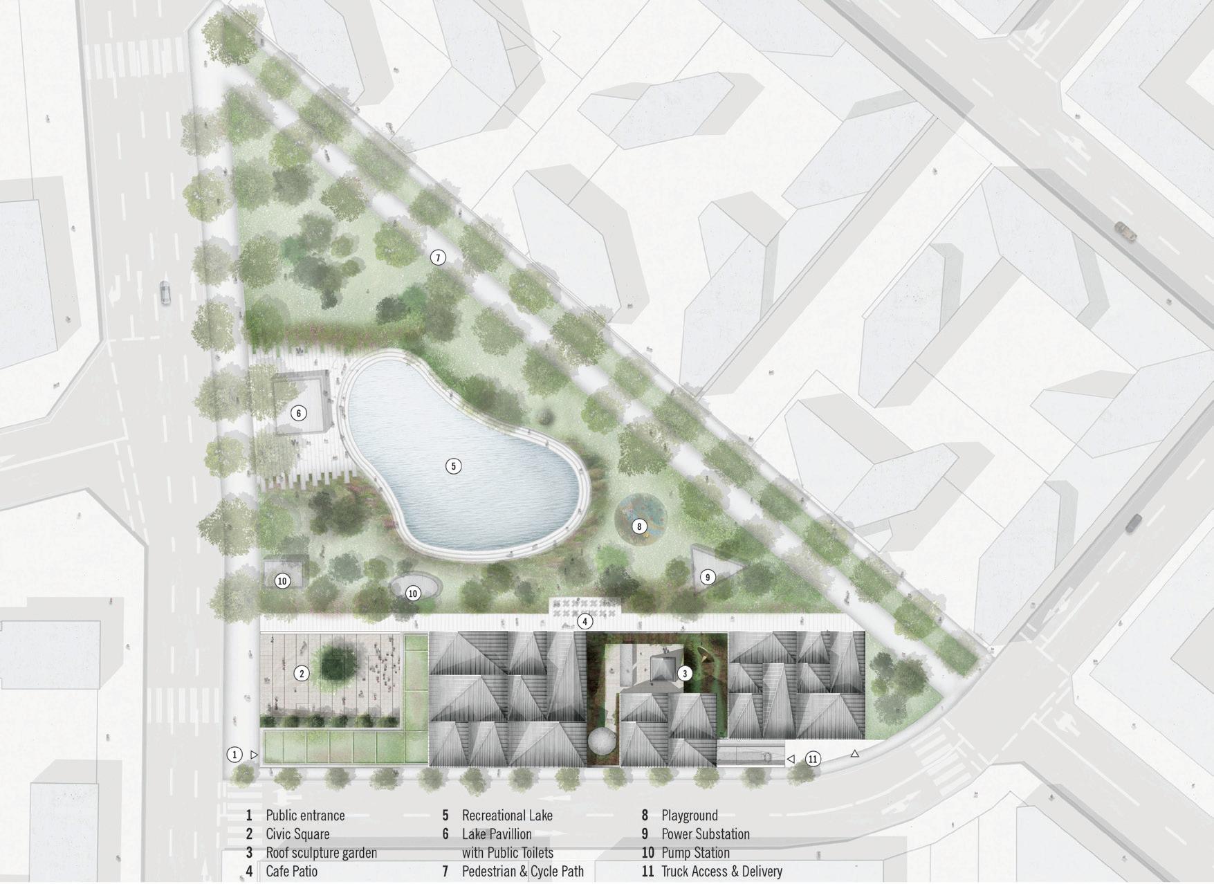
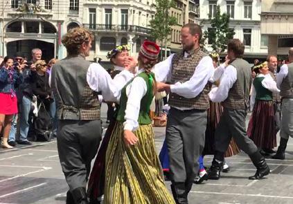
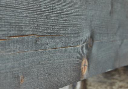
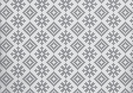
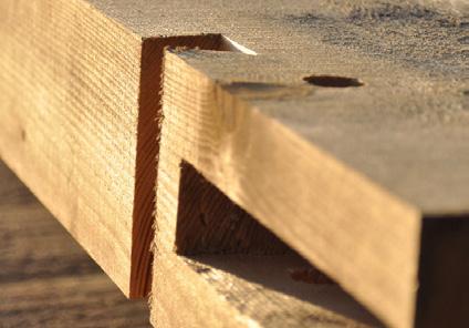
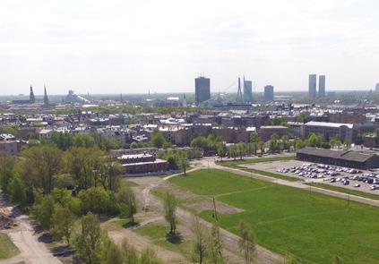
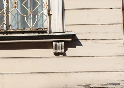
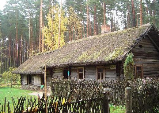
Inspiration Elements of the Latvian Culture
Massing Diagrams
75
Latvian Traditionnal
Verticality
horizon Traditionnal Timber Housing Burnt Timber Structural Timber Timber Cladding Timber on a Concrete Plinth SITE CUT GROUND PLANE GALLERIES ROOF Site Cut Ground Plane Roof Galleries
Latvian Open Air Dance
Pattern
breaking
Competition Proposal Site Plan
Latvian Traditionnal
Traditionnal Timber
Structural Timber Timber Cladding Timber on a Concrete Plinth
Latvian Open Air Dance
Pattern Verticality
breaking horizon
Housing Burnt Timber
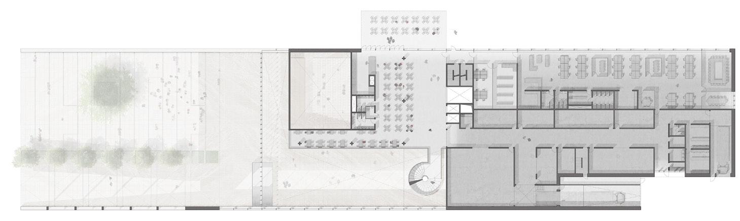
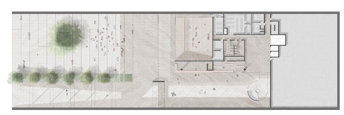
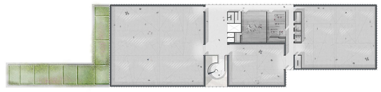
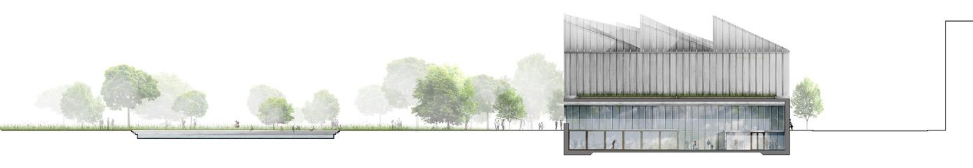
76 Ground Floor Plan 1/500 1 Cafe Kitchen 2 Public Toilets 3 Cafe 4 Cafe Patio 5 Artifact Lift 6 Public Lift 13 Kitchenette 14 Showers 15 Locker Rooms 16 Staff Toilets 17 Back-of-House Corridor 18 Receiving / Packing 19 Artifact Loading Bay with Hydraulic Platform 20 Collection storage 21 Cleaning Storage 22 Quarantine 23 Digitalization 24 Crate Storage 25 IT Room / AV Storage 26 Warehouse for Exhibition Props 27 General Storage 28 Maintenance Workshop with Tool Storage 29 Delivery Loading Bay 30 Meetings and Working Room 31 Locker Room, Showers, Toilets 32 Waste & Recycle Room 7 Staff Lift 8 Co-Working Space 9 Library - Archive 10 Reception 11 Offices 12 Meeting Rooms 5 4 3 1 6 2 8 9 21 22 23 17 18 19 20 27 26 32 28 30 31 10 16 15 14 13 12 12 12 29 24 25 11 7 1 Civic Space 2 Accessible Ramp 3 Vestibule 10 Auditorium 11 Projection & Recording Room 12 Translation 15 Main Kitchen, Preparation Space, Storages, Offices, etc 16 Artifact Lift Basement Plan 1/500 6 Cloakroom 7 Museum Shop 8 Exterior Performance Place 3 2 4 1 First Floor Plan 1/500 2 1 3 5 6 7 8 4 9 10 11 1 Large Gallery 2 Medium Gallery 3 Small Gallery 7 Cloakroom 8 Public Toilets 9 Artifact Lift 10 Public Lift 11 Staff Lift 4 Gallery Atrium 5 Children’s Art Gallery 6 Event Space FLOOR PLANS Competition Scheme Ground Floor Plan 1/500 1 Cafe Kitchen 2 Public Toilets 3 Cafe 4 Cafe Patio 5 Artifact Lift 6 Public Lift 13 Kitchenette 14 Showers 15 Locker Rooms 16 Staff Toilets 17 Back-of-House Corridor 18 Receiving / Packing 19 Artifact Loading Bay with Hydraulic Platform 20 Collection storage 21 Cleaning Storage 22 Quarantine 23 Digitalization 24 Crate Storage 25 IT Room / AV Storage 26 Warehouse for Exhibition Props 27 General Storage 28 Maintenance Workshop with Tool Storage 29 Delivery Loading Bay 30 Meetings and Working Room 31 Locker Room, Showers, Toilets 32 Waste & Recycle Room 7 Staff Lift 8 Co-Working Space 9 Library - Archive 10 Reception 11 Offices 12 Meeting Rooms 5 4 3 1 6 2 8 9 21 22 23 17 18 19 20 27 26 32 28 30 31 10 16 15 14 13 12 12 12 29 24 25 11 7 1 Civic Space 2 Accessible Ramp 3 Vestibule 4 Foyer Atrium 5 Reception 10 Auditorium 11 Projection & Recording Room 12 Translation 13 Green Room 14 Public Toilets 15 Main Kitchen, Preparation Space, Storages, Offices, etc 16 Artifact Lift 17 Public Lift 18 Staff Lift Basement Plan 1/500 6 Cloakroom 7 Museum Shop 8 Exterior Performance Place 9 Break-Out Space with Sliding Doors 12 13 15 10 9 3 8 1 2 4 11 6 5 7 14 19 16 17 18 ELEVATIONS East Elevation 1/500 West Elevation 1/500 North Elevation 1/500 ELEVATIONS East Elevation 1/500 West Elevation 1/500 North Elevation 1/500 South Elevation 1/500 ELEVATIONS East Elevation 1/500 West Elevation 1/500 North Elevation 1/500 South Elevation 1/500
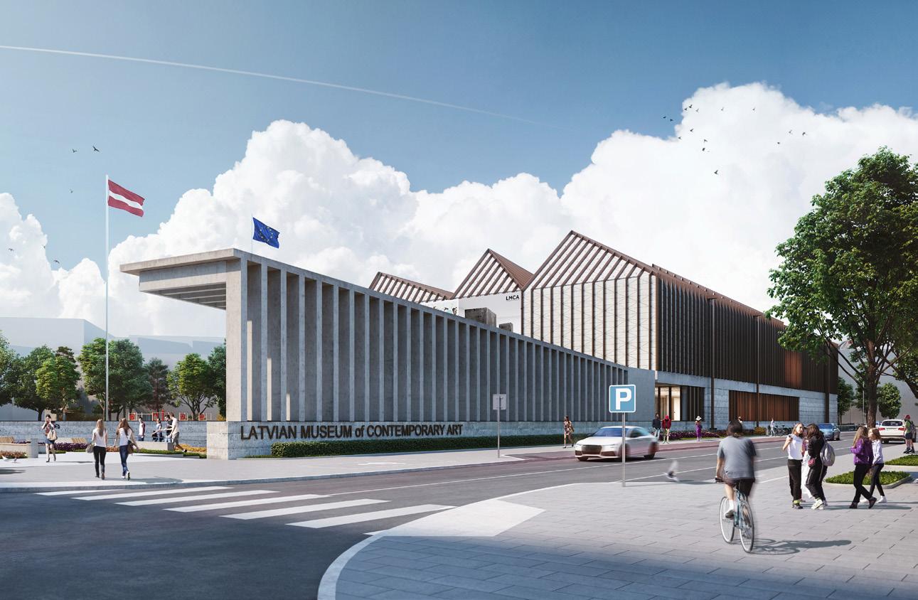
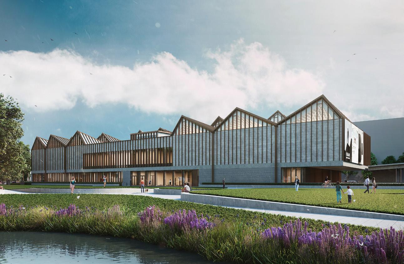
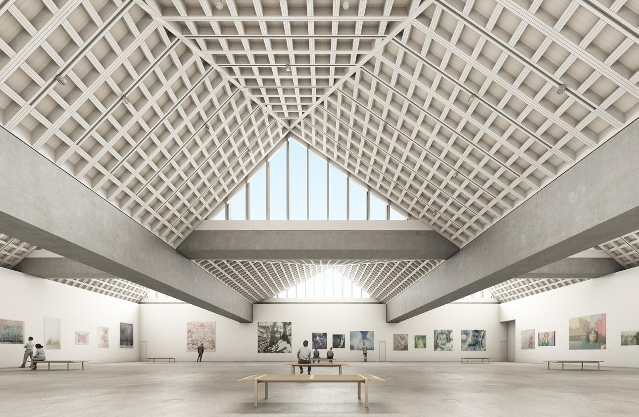
Drawing Visualizations
78
LATVIAN MUSEUM OF CONTEMPORARY ART
GALVENĀ IEEJA
LATVIAN MUSEUM OF CONTEMPORARY ART
GALVENĀS GALERIJAS TELPA (VAĻĒJS PLĀNOJUMS)
Stage 4
materiāli. Sekojot šiem principiem tiek piedāvāta augstas kvalitātes materiālu palete. Slāņveida betona cokols pastiprina attiecības ar zemes plakni, radot svara un noturības sajūtu, vienlaikus organizējot zonas ap stiklotajām daļām. Slāņainā betona augšpuse veido taisnu ēkas perimetra joslu un atklāj pārseguma plātnes līniju. Šī josla norāda uz konstrukciju spēku veidojot lielos pārsegumus un plašajiem atvērumiem gar ēkas pirmo stāvu un pagrabstāva ieeju.
Piezīmes: 1-Rasējums āskata kopā ar specifikācijām un citiem saistošajiem rasējumiem. 2-Rasējumu nemērīt, lasīt rakstītos izmērus. 3-Izpildītājs
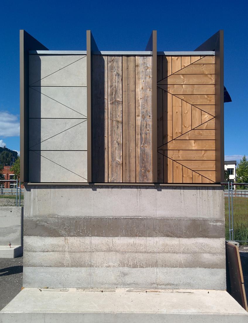
Kā otrā stāva fasādes un jumta apšuvumam ieteicams pielietot dabīgās akmens (dolomīts) plāksnes, kas iegūtas no Baltijas reģiona. Diognālās līnijas, kuras atsavinātas no slīpajiem jumtiem, ieteicams veidot kā viena metra moduļus. Dolomīta akmens rada izturības sajūtu, kas atbilst nepieciešamajai muzeja misijai.
organizējot zonas ap stiklotajām daļām. Slāņainā betona augšpuse veido taisnu ēkas perimetra joslu un atklāj pārseguma plātnes līniju. Šī josla norāda uz konstrukciju spēku veidojot lielos pārsegumus un plašajiem atvērumiem gar ēkas pirmo stāvu un pagrabstāva ieeju. Kā otrā stāva fasādes un jumta apšuvumam ieteicams pielietot dabīgās akmens (dolomīts) plāksnes, kas iegūtas no Baltijas reģiona. Diognālās līnijas, kuras atsavinātas no slīpajiem jumtiem, ieteicams veidot kā viena metra moduļus. Dolomīta akmens rada izturības sajūtu, kas atbilst nepieciešamajai muzeja misijai.
Tas pats akmens tiek pielietots jumta un fasādes apdarē. Projektēšanas mērķis ir vertikālo fasādi un slīpo jumtu veidot kā vienu elementu.
Tas pats akmens tiek pielietots jumta un fasādes apdarē. Projektēšanas mērķis ir vertikālo fasādi un slīpo jumtu veidot kā vienu elementu. Kā dalījuma joslas elements, logu rāmjiem, sliekšņiem un nosegelementiem tiek piedāvātas bronzas krāsas metāla izstrādājumi. Kontrastu starp metāla konstrukcijām un pirmā stāva grīdas pārseguma materiālu papildinās ar juceklīgu tekstūru, kas veido kustības sajūtu uz fasādes tiklīdz
Kā dalījuma joslas elements, logu rāmjiem, sliekšņiem un nosegelementiem tiek piedāvātas bronzas krāsas metāla izstrādājumi. Kontrastu starp metāla konstrukcijām un pirmā stāva grīdas pārseguma materiālu papildinās ar juceklīgu tekstūru, kas veido kustības sajūtu uz fasādes tiklīdz dabīgā gaisma plūst pāri šīm formām. Visas sadalošās joslas ir izvietotas ar viena metra atstarpi, un šis modulis atbilst strukturālajam posmam, kas sadala visu ēku. Mazās atstarpes starp sadalošajām joslām veido divpusīgu
Atbildīgais
28 A, Rīga, Latvija, LV tālr.: 67015666, fax: 67015600, e
Autors/ Design author: "ADJAYE ASSOCIATES" The Edison 223-231 Old Marylebone Road, London NW1 5QT tālr.: +44(0)2072586140, e-pasts: lmca@adjaye.com
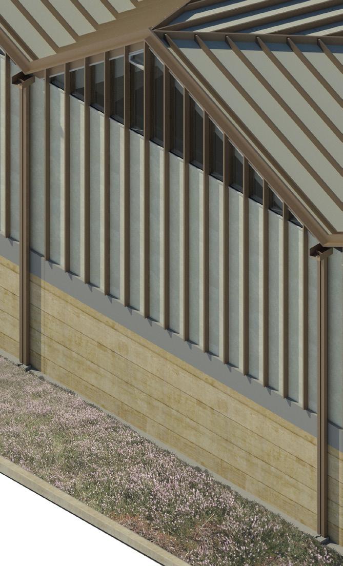
Stage 3 Mockup Fabrication and Facade Studies
AB3D, SIA Reģ. Nr. 40003514454 Peitavas iela 10, Rīga, LV-1050, tālr.: 67227734, e-pasts: ab3d@ab3d.lv Būvprojekta daļas izstrādātājs/ Subdesigner:
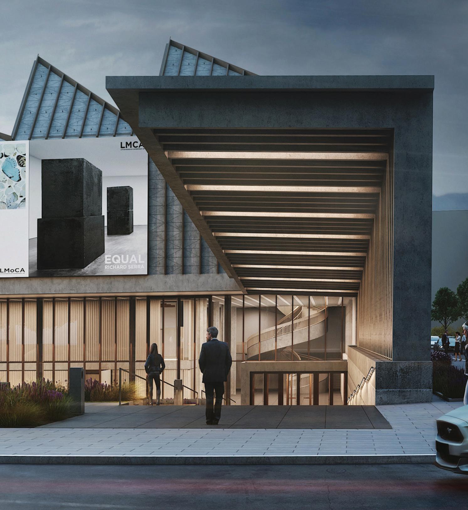
Labiekārtojums Stage 4 Drawing Studies
79 LATVIAN MUSEUM OF CONTEMPORARY ART FASĀDES MAKETS (DECEMBRIS 2017) LATVIAN MUSEUM OF CONTEMPORARY ART 18 IEEJAS NOJUMES MEZGLS C FF3x Constructive System - Concrete - Wool Insulation - Rigid Insulation - Air Space - Bitumen Waterproofing - Geotextil Membrane - Wind Insolation Membrane - Dolomite Stone - Steel - Bitumen Primer - Waterproofing Membrane - Filter Sheet 01 0 A B1 -3350 1 32004 2 32004 01 0 B1 -3350 8 7 B2 -4350 3 32004 4 32004 W11 W10 Rasējuma Nr./Drawing No.: AR daļas vadītājs Checked By: Mērogs/Scale: Datums/Date: General Notes: 1-Drawing to be read in conjunction with the specification and all relevant drawings. 2-Do not scale from this drawing. 3-Contractor to check all dimensions on site. Adjaye Associates to be advised of any discrepancies between this drawing and site conditions immediately. The Edison 223-231 Old Marylebone Road London NW1 5QT Phone: +44 (0)20 7258 6140 email: info@adjaye.com
būvprojekta izstrādātājs/Responsible designer: Pillar Architekten, SIA Reģ. Nr. 40103437217 Pulkveža Brieža iela
pārbauda visus
Adjaye Associates nekavējoties āinformē par jebkādām pretrunām starp šo rasējumu un vietas apstākļiem. Paraksts/Sign: Marka/Part: Lapas Nr/Page No: Lapas /Total No of Pages: J.Mitenbergs AR Izstrādāja/Drawn By Paraksts/Sign: P. Spuriņš As indicated @ A1 18.06.29 NHG-AA-XX-ZZ-DR-AR-31003 1 : 500 Key Section 1 : 50 West Facade Section 1 Entrance Canopy 1 : 50 West Facade Section 2 Entrance Canopy Ieejas nojumes skats no galvenās ieejas pandusa Ieejas nojumes mezgli LATVIAN MUSEUM OF CONTEMPORARY ART 13 Ziemeļu fasādes griezums Ziemeļu fasādes aksonometrija FASĀDES ELEMENTU SAVIENOJAMĪBA 01 ROOF 1 4045 W10 F8 1000 12650 01 ROOF 1 1 32000 3 32000 32000 F2 C4 C6 12710 01 ROOF 1 32000 32000 F2 12710 Technical Gallery 1500 1 North Facade Section 1 North Facade Section 2 North Facade Section 3 North Facade Section 4 Piedāvātā materiālu palete Latvijas Laikmetīgās mākslas muzejam cenšas pastiprināt ēku tradīcijām Rīgā, vienlaikus ņemot arī vērā arī tehniskās prasības, ugunsdrošības noteikumus un materiālu novecošanu. Fasādes apdarei ir paredzēti izturīgi,viegli kopjami, ilgtspējīgi ārējās apdares
izmērus uz vietas.
fasādi, kas paplašina ēkas dinamiku: skatoties fasādi pretskatā tā tiek uztverta kā akmens fasāde, taču skatoties uz to no leņķa, tā veido vertikālu bronzas elementu fasādes dalījumu. Virsgaismas stiklojums Dūmu lūka Dolomīta plākšņu fasādes apdare Vertikāli profili (bronza) Notekcaurule Gluda betona josla Slāņveida betons Fasādes apgaismojums Labiekārtojums LATVIAN MUSEUM OF CONTEMPORARY ART 13 North Facade Section North Facade Axonometric FACADE ARTICULATION 02 5850 GALLERY ROOF 12000 ROOF 1 B2 -4350 C1 W18 1000 Technical Wall 02 5850 GALLERY ROOF 12000 ROOF 1 B2 -4350 32000 3 32000 32000 W7 W1 F2 F4 A.F.F. C6 12710 CW5 Technical Wall 02 5850 GALLERY ROOF 12000 ROOF B2 -4350 8 W6 W18 12710 CW5 Technical Gallery 1500 B2 -4350 F2 50 North Facade Section 1 50 North Facade Section 4 The proposed material palette for the Latvian Museum of Contemporary Art seeks to reinforce the building’s relationship with the building tradition in Riga whilst also taking into consideration technical requirements, fire regulations and the ageing of the materials. The external envelope materials are intended to be low maintenance, durable and convey a sense of permanence. Following these principles a restrained palette of high quality materials is proposed. A layered concrete plinth which seeks to reinforce the relationship with the ground plane conveying a sense of weight and permanence while organizing the public areas of the programme around glazed openings. Atop the layered concrete a fair-face concrete fascia runs the perimeter of the building and reveals its slab line. This fascia expresses the structural forces at play in the large overhangs and above the wide openings along the ground floor and basement entrance. A natural stone sourced from the Baltic region (Dolomite) is suggested for the second floor facade and roof cladding. A diagonal pattern derived from the lines of the pitched roofs is proposed with the 1m module. The dolomite stone conveys a sense of durability which is in-keeping with the museum’s mission. The same stone continues seamlessly from the façades to the roof. The design intention is for the vertical facade and pitched roof to read as one element. Bronze coloured metalwork is proposed for mullions, window frames, sills and capping. The contrast between the metalwork and the first floor material will add an intricate texture and a sense of movement to the facade as the light catches these shapes. All mullions are spaced 1 metre apart, this module is consistent with the structural bay and orders the entire building. The close spacing between mullions allows for a dual perception of the facades which adds to the dynamic of the building: when viewed in elevation the facade is perceived as stone, when viewed obliquely the facade will look composed of bronzed verticals. Clerestory Glazing Fire Extraction Hatch Dolomite Stone Facade Bronzed Mullions Downpipe Fair-Face Concrete Fascia Layered Concrete External Up-lights Landscape LATVIAN MUSEUM OF CONTEMPORARY ART Ziemeļu fasādes griezums Ziemeļu fasādes aksonometrija
ELEMENTU
01 02 GALLERY ROOF 1 B2 C1 4045 W7 W18 1000 CW4 CW1 01 02 GALLERY ROOF 1 B2 32000 3 32000 W7 W1 W18 F2 F4 F7 A.F.F. C6 01 02 GALLERY ROOF 1 B2 8 W6 W1 F2 F4 F7 R2 4400 W18 C4 Technical Gallery 1500 01 02 GALLERY ROOF 1 B2 13 11 F2 W18 CW6 North Facade Section 1 North Facade Section 2 North Facade Section 3 North Facade Section 4 Piedāvātā materiālu palete Latvijas Laikmetīgās mākslas muzejam cenšas pastiprināt ēku tradīcijām Rīgā, vienlaikus ņemot arī vērā arī tehniskās prasības, ugunsdrošības noteikumus un materiālu novecošanu. Fasādes apdarei ir paredzēti izturīgi,viegli kopjami, ilgtspējīgi ārējās apdares materiāli. Sekojot šiem principiem tiek piedāvāta augstas kvalitātes materiālu palete. Slāņveida betona cokols pastiprina attiecības ar zemes plakni, radot svara un noturības sajūtu, vienlaikus
FASĀDES
SAVIENOJAMĪBA
dabīgā gaisma plūst pāri šīm formām. Visas sadalošās joslas ir izvietotas ar viena metra atstarpi, un šis modulis atbilst strukturālajam posmam, kas sadala visu ēku. Mazās atstarpes starp sadalošajām joslām veido divpusīgu fasādi, kas paplašina ēkas dinamiku: skatoties fasādi pretskatā tā tiek uztverta kā akmens fasāde, taču skatoties uz to no leņķa, tā veido vertikālu bronzas elementu fasādes dalījumu. Virsgaismas stiklojums Dūmu lūka Dolomīta plākšņu fasādes apdare Vertikāli profili (bronza) Notekcaurule Gluda betona josla Slāņveida betons
apgaismojums
Fasādes
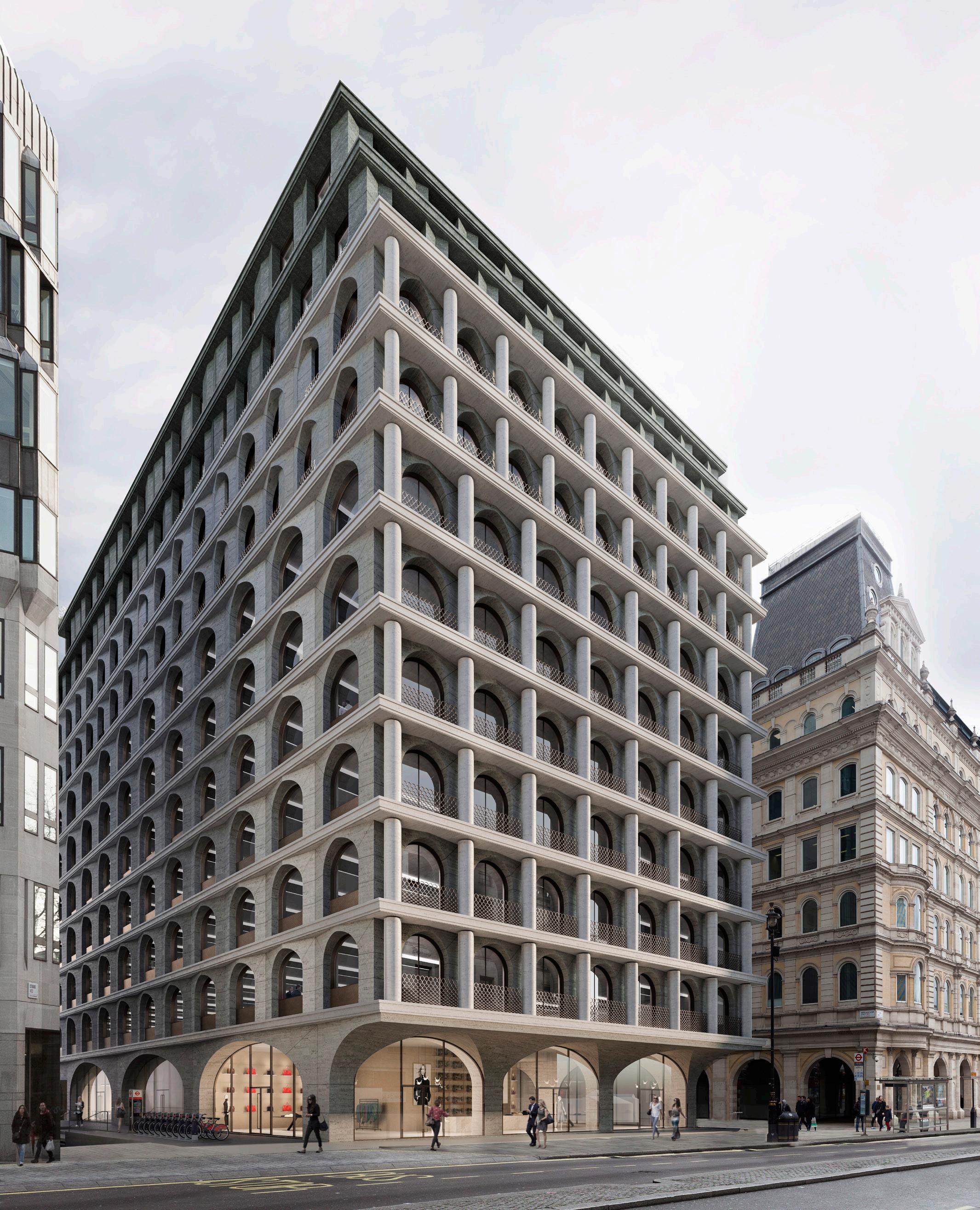
FIVE STRAND
(Competiton, Winning Scheme)
14.000m2 Resi/Office Complex London, UK
RIBA Stages 1-3 (Planning Approved - Unbuilt) 2015
In November of 2014 Adjaye Associates partnered with development manager Alchemi to redevelop an existing commercial property at 5 Strand. The new scheme will provide 62.000 sq. ft. of rade A office space plus two retail units on the ground floor. In addition, the building will provide 26 premier apartments with separate concierge manned entrance on Craven Street. Important considerations in the brief included the buildings position in Trafalgar Square conservation area, adjacent to the cultural heritage site of the square. Adjaye Associates design concept responds directly to the project iconic location by drawing on the key forms and textures of the area. The design draws inspiration from similar textures and materials used on other key buildings in the area, which is defined by 19th and 20th century buildings of grand civic scale.
80
7 surrounding
Fig.1.1 View of the Proposal from The Strand
In particular the recurring arch and column motif evident along Trafalgar Square, The Strand, The mall, and Pall Mall has been reinterpreted through the use of a contemporary material palette of stone and bronze. The building reacts differently to each of the surrounding streets. While the side facades facing Northumberland Street and Craven Street are more restrained, the front facade responds to the ceremonial nature of The Strand and juxtaposes a layer of columns to the arches. This gesture adds another layer of complexity to the facade promoting a subtle play of depth and showers.
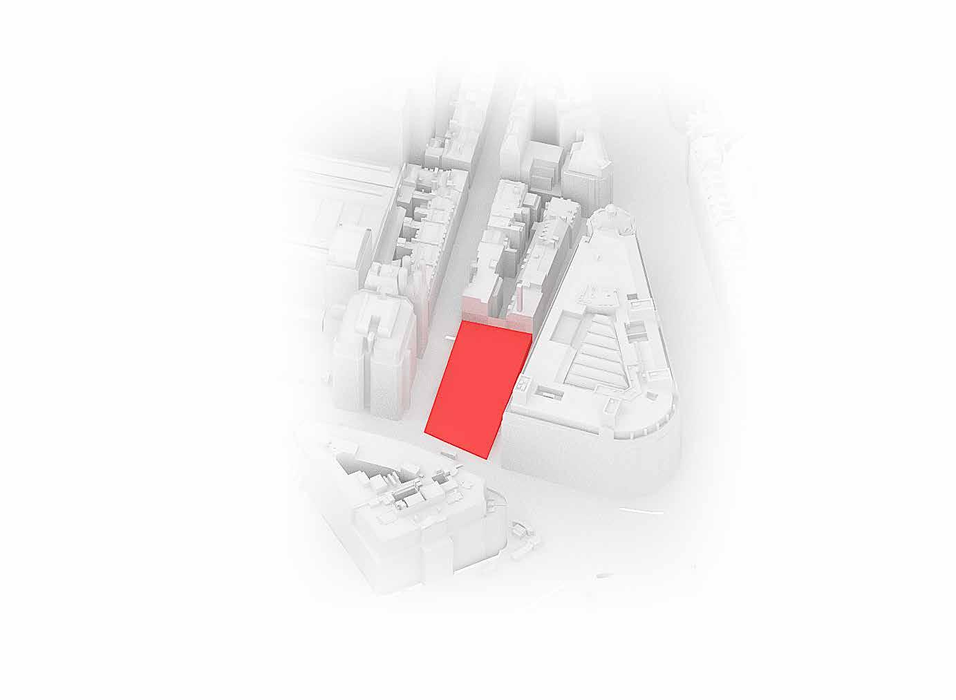
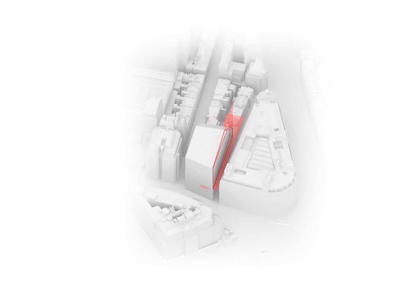
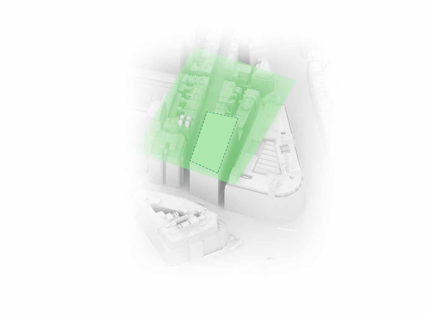
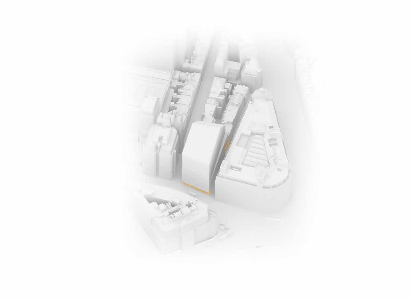
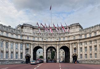
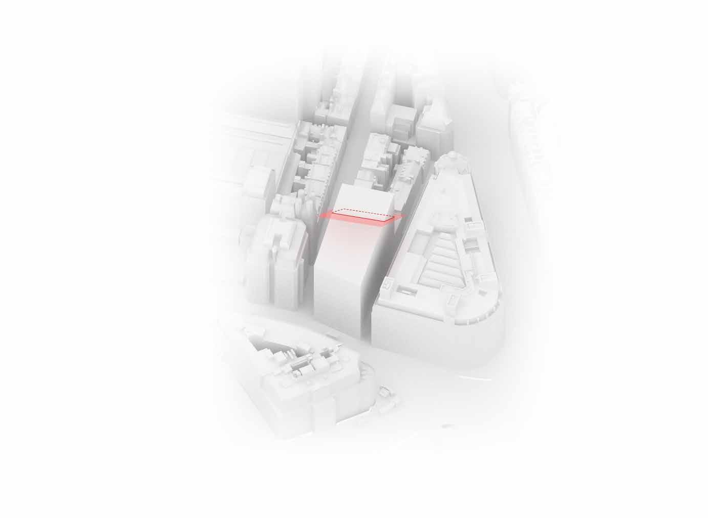
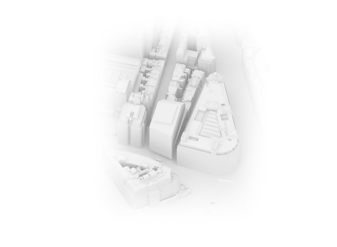
Residential use: Apartments are situated at the upper levels of the building from the seventh floor onwards. They are organised around the core and face the four façades. Apartments on the rear façade step back as they go higher adhering to daylight and sunlight guidelines as governed by the Building Research Establishment. There are 26 apartments spread over five floors of a range of sizes. Residents enter their lobby from Craven Street. Bicycle parking and residential storage are located in the basement and accessed through Corner House Street or via elevator directly from the apartments’ lobby. Due to the limited site footprint and underground constraints, no car parking has been provided on site.
• Residential use: Apartments are situated at the upper levels of the building from the seventh floor onwards. They are organised around the core and face the four façades. Apartments on the rear façade step back as they go higher adhering to daylight and sunlight guidelines as governed by the Building Research Establishment. There are 26 apartments spread over five floors of a range of sizes.
Residents enter their lobby from Craven Street. Bicycle parking and residential storage are located in the basement and accessed through Corner House Street or via elevator directly from the apartments’ lobby. Due to the limited site footprint and underground constraints, no car parking has been provided on site.
• Retail: Located on the ground floor of the building, the proposal provides two retail units. An A1 unit facing the Strand and another A1 and / or A3 unit facing Craven Street, Corner House Street and Northumberland Street. Customers enter the shops directly from the Strand and Craven Street.
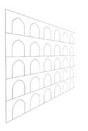
• Retail: Located on the ground floor of the building, the proposal provides two retail units. An A1 unit facing the Strand and another A1 and / or A3 unit facing Craven Street, Corner House Street and Northumberland Street. Customers enter the shops directly from the Strand and Craven Street.
• Office: Offices are located at the lower levels of the building, from the first to the sixth floor. The access core is located in the centre of the floor plate which releases the perimeter of the building and maximises window area.
• Office: Offices are located at the lower levels of the building, from the first to the sixth floor. The access core is located in the centre of the floor plate which releases the perimeter of the building and maximises window area.
• Shared
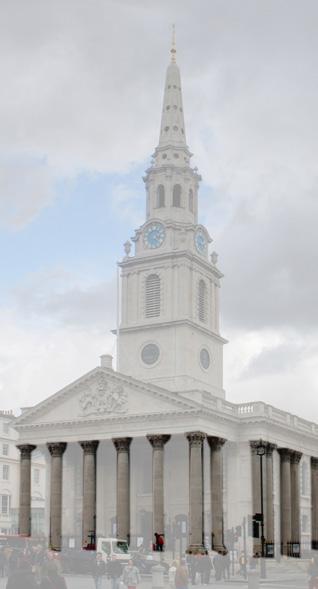
• Shared Servicing: The loading bay on the lower ground floor 02 serves both the office and residences, while the retail units will be serviced directly from Craven Street and the Strand.
• Plant: Most of the plant rooms supporting the building are located in the basement with just the minimum amount of plant equipment at roof level, always behind screens created specifically to hide it.
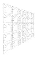
81 MASSING ANALYSIS FOOTPRINT This is a copy of the title that time if still pending This copy is not an 'Official the same extent as the of mistake in official The Land Registry endeavours of any print will depend not the exact line, of the not match measurements This title is dealt with Land registry title NGL907153 Local view from Charing Cross Road Local View from Charing Cross Road MASSING ANALYSIS MAXIMUM HEIGHT National Portrait Gallery- Charing Cross Rd MASSING ANALYSIS DAYLIGHT AND SUNLIGHT D&Sclippingplan Daylight and Sunlight Setback plane 04. Height Alignment on Northumberland Street MASSING ANALYSIS LAND REGISTRY DEED MAGE 02 GIA’s interpretation of this extract is that any development on the Northumberland Street frontage (from point A to the extent of the red line on image 02) can build to height of 52ft from the pavement edge. What is not clear from review of this transfer is if there is an angle from which this height has to b back. We would recommend you seek your own independent review of this document from legal advisor. 5-6 STRAND FH AGREEMENT – 123178 An Agreement as to building dated 31 December 1929 was made between (1) Lyons & Company Limited (2) The Southern Railway Company (3) The Right Honourable Algerno Hawkins Thomond Keith Falconer Earl of Kintore K.T., K.C.M.G. and others (4) Frederick D'Abernon Vincent Sir Harold Pelly, Baronet and Sir William Pitcairn Campbell K.C.B., and (5) The North British & Mercantile Insurance Company Limited. 03 2 Existing Setback corresponds to initial analysis of legal deed 05. Rights of Way MASSING ANALYSIS RIGHTS OF WAY PASSAGE Rights of Way within building footprint 06. Pent House on the Top stepped back. Maximum envelope MASSING ANALYSIS MAXIMUM ENVELOPE 1.
Site boundary
4.
Height Alignment on Northumberland Street, existing setback corresponds to initial analysis of legal deed 2. Boundary extruded to maximum height as per limitations by London Metropolitan protected views
5. Rights of Way within building footprint and car passage at Corner House Street 3. Daylight and sunlight constrains in regards to neighboring residential buildings
Strand. Design and Access Statement. November 2016 3.0 Design Considerations Trafalgar Square is the centre of the confluence of several main thoroughfares connecting the capital’s political, cultural and commercial cores, namely The Mall, Strand, and Whitehall. Three main architectural styles are prevalent along these routes: the classical language of Trafalgar Square and The Mall; the Gothic of Westminster Abbey and the Gothic Revival of the Palace of Westminster; and the modern language of some of the recent commercial developments along the Strand. The proposed façade geometry references both the classical and pointed arch as a response to its context. Points of consideration: Standardisation of the classical arch element can help continue the existing Conservation Area’s approach to architectural language. The arch module consists of a splayed surface intersected by a round arch. This geometry will be perceived as round arch or a pointed arch depending on the viewpoint. The building will therefore take on different aspects when seen from different viewpoints. • Emphasising the floor plate edge and varying arch placement as the building proceeds upwards creates modulation and regularity which adheres to classical architectural characteristics. 3.9 FAÇADE LANGUAGE Fig.3.97 Westminster Abbey external pointed arch Fig.3.99 Westminster Abbey interior arches Fig.3.100 Saint Martin-in-the-Fields classical colonnade outline Fig.3.101 Round arch of Admiralty Arch Fig.3.102 Fig.3.98 Combined architectural language diagram City of London Mall Buckingham Palace Westminster Abbey Palace of Westminster National Gallery St. Martin-in-the-Fields 69 5 Strand. Design and Access Statement. November 2016 3.0 Design Considerations Fig.3.97 Westminster Abbey external pointed arch arches Fig.3.100 Saint Martin-in-the-Fields classical colonnade Fig.3.101 Round arch of Admiralty Arch Fig.3.102 Side elevation of St. Martin-in-the-Fields Fig.3.98 Combined architectural language diagram City of London Mall Buckingham Palace Westminster Abbey Palace of Westminster National Gallery St. Martin-in-the-Fields 69 Strand. Design and Access Statement. November 2016 3.0 Design Considerations Pointed Arch Pointed Arch floor progression Combined arch floor progression (Achieves classical arch in elevation) Pointed Arch Perspective progression Proposed combined Arch Module Round arch Perspective Combined arch perspective Strand. Design and Access Statement. November 2016 3.0 Design Considerations Round Arch Pointed Arch floor progression Combined arch floor progression (Achieves classical arch in elevation) Pointed Arch Perspective Round Arch floor progression Proposed combined Arch Module Round arch Perspective Strand. Design and Access Statement. November 2016 3.0 Design Considerations Round Arch Pointed Arch Pointed Arch floor progression Combined arch floor progression (Achieves classical arch in elevation) Pointed Arch Perspective Round Arch floor progression Proposed combined Arch Module Round arch Perspective Combined arch perspective
6. PentHouse on the top stepped back. Maximum envelope
81 5 Strand. Design and Access Statement. November 2016 4.0 Design Proposals 4.1
The building is mixed use consisting of retail, office and residential and there are separate access points for each. The separate lobbies enhances the active street frontages. The scheme is organised around two vertical cores; one serving the offices and another dedicated for residents. This separation in access and circulation paths provides clarity of ownership and security. •
BUILDING ORGANISATION
loading bay
lower ground floor 02 serves both the office
residences, while the retail units will be serviced directly from Craven Street
the Strand.
plant rooms
building
located
basement
just
minimum
plant equipment
roof level, always behind screens created specifically to hide it. Ground Floor Lower Ground Floor Basement Floors Level 1-6 Level 7- 9 Level 10 Roof Level Office Residential Retail Cores / Vertical Circulation Plant 81 5 Strand. Design and Access Statement. November 2016 4.0 Design Proposals 4.1 BUILDING ORGANISATION The building is mixed use consisting of retail, office and residential and there are separate access points for each. The separate lobbies enhances the active street frontages. The scheme is organised around two vertical cores; one serving the offices and another dedicated for residents. This separation in access and circulation paths provides clarity of ownership and security. • Residential use: Apartments are situated at the upper levels of the building from the seventh floor onwards. They are organised around the core and face the four façades. Apartments on the rear façade step back as they go higher adhering to daylight and sunlight guidelines as governed by the Building Research Establishment. There are 26 apartments spread over five floors of a range of sizes. Residents enter their lobby from Craven Street. Bicycle parking and residential storage are located in the basement and accessed through Corner House Street or via elevator directly from the apartments’ lobby. Due to the limited site footprint and underground constraints, no car parking has been provided on site. • Retail: Located on the ground floor of the building, the proposal provides two retail units. An A1 unit facing the Strand and another A1 and / or A3 unit facing Craven Street, Corner House Street and Northumberland Street. Customers enter the shops directly from the Strand and Craven Street. • Office: Offices are located at the lower levels of the building, from the first to the sixth floor. The access core is located in the centre of the floor plate which releases the perimeter of the building and maximises window area. • Shared Servicing: The loading bay on the lower ground floor 02 serves both the office and residences, while the retail units will be serviced directly from Craven Street and the Strand. • Plant: Most of the plant rooms supporting the building are located in the basement with just the minimum amount of plant equipment at roof level, always behind screens created specifically to hide it. Ground Floor Lower Ground Floor Basement Floors Level 1-6 Level 7- 9 Level 10 Roof Level Office Residential Retail Cores Vertical Circulation Plant 81 5 Strand. Design and Access Statement. November 2016 4.0 Design Proposals 4.1 BUILDING ORGANISATION The building is mixed use consisting of retail, office and residential and there are separate access points for each. The separate lobbies enhances the active street frontages. The scheme is organised around two vertical
Servicing: The
on the
and
and
• Plant: Most of the
supporting the
are
in the
with
the
amount of
at
cores; one serving the offices and another dedicated for residents. This separation in access and circulation paths provides clarity of ownership and security.
Ground Floor Lower Ground Floor Basement Floors Level 1-6 Level 7- 9 Level 10 - Roof Level Office Residential Retail Cores / Vertical Circulation Plant
82 Typical Office Floor Plan 4.0 Design Proposals Floors: areas
organized
perimeter
building.
are
around a central
of the
northern side of the building is intended and informal meetings as it engages balconies are provided.
floor
stations reception
flexible
tenancies
core.
circulation
well as amenities such
rest
rooms
meeting
elements
designed
allow access maintaining complete separation residential floors above. Additional is dispersed within the core to floor space and keep barriers to columns, to a minimum. Fig.4.173 Typical floor plan - levels 1-6 Tea Point IT Room AWC Meeting Room 01 Meeting Room 02 Plant W/C W/C Breakout Space Informal Meeting Informal Meeting Strand Office Northumberland Street Craven Street Reception Typical Residential Floor plan 119 and Access Statement. November 2016 TH to 9TH Floors: provide residential apartments ranging from The apartments are all accessed through and are within the maximum fire escape layouts conform to the London Housing Standards and 10% are easily adaptable ‘‘Wheelchair Accessible Housing Best Guidance’’. residential floors go up the building they step northern and southern sides to minimise respecting townscape views on key public apartment layouts are designed to maximise and views, whilst maintaining an efficient use shape of the floor plate provides a good create a mix of apartment sizes but still connectivity to the central core. Fig.4.174 Residential floor plan - levels 7-9 3 Bed Apartment 7.1 1 Bed Apartment 7.2 1 Bed Apartment 7.3 3 Bed Apartment 7.4 1 Bed Apartment 7.5 2 Bed Apartment 7.6 1 Bed Apartment 7.7 2 Bed Apartment 7.8 3 Bed Apartment 7.9 Strand
Street
Street
sides of the floor are designed to
plate for the working
and meetings rooms in between. layout is
and can be broken
or cells with no adjustments
houses the main vertical
to
as
rooms,
and
rooms. The
are
to
Northumberland
Craven
The seventh and eight floors are both clad with the
The
Similarly to the front façade, the Craven Street elevation maintains a tripartite subdivision. The arches on the ground floor follow the same height as on the main elevation while the difference in levels between the Strand Corner House Street is compensated through a plinth. This plinth provides a ‘‘podium’’ on which the proposed building stands.
Similarly to the front façade, the Craven Street elevation maintains a tripartite subdivision. The arches on the ground floor follow the same height as on the main elevation while the difference in levels between the Strand Corner House Street is compensated through a plinth. This plinth provides a ‘‘podium’’ on which the proposed building stands.
to the narrow width of Craven Street, a shallower façade is proposed in order to increase the internal daylight and sunlight levels. The secondary layer of columns present on the Strand façade is omitted.
to the narrow width of Craven Street, a shallower façade is proposed in order to increase the internal daylight and sunlight levels. The secondary layer of columns present on the Strand façade is omitted.
difference on the architectural articulation between front and side elevations provides a subtle transition between the different nature of the Strand and the side streets.
difference on the architectural articulation between front and side elevations provides a subtle transition between the different nature of the Strand and the side streets.
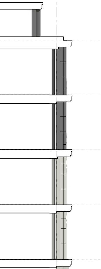
From the seventh to the eighth floor, the proposed façade articulation is similar to the one proposed for the Strand, however, some blind panels are incorporated to allow for flexibility in the internal layouts without compromising the concept of the scheme. This gesture also helps to increase the thermal efficiency of the envelope.

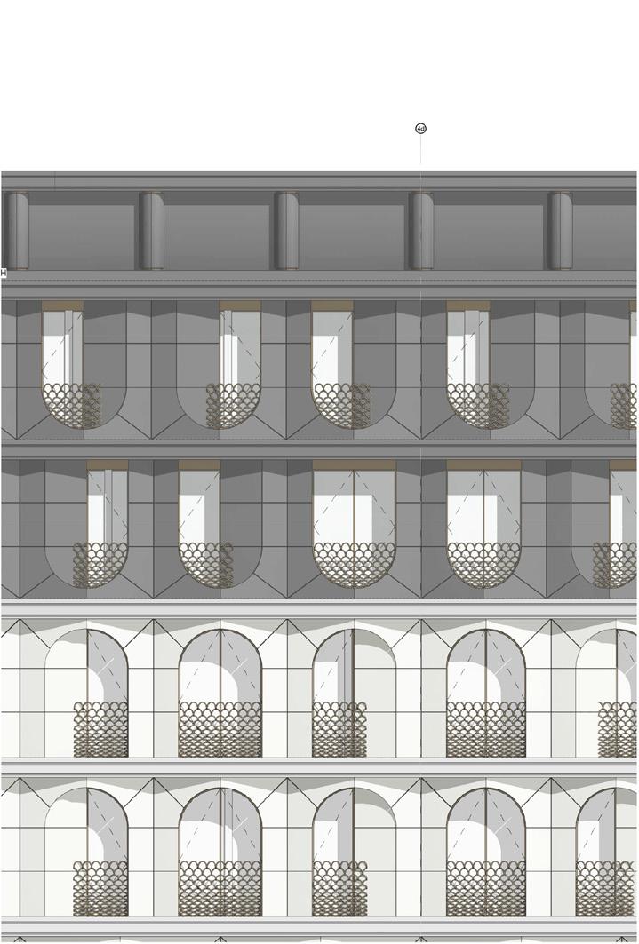
From the seventh to the eighth floor, the proposed façade articulation is similar to the one proposed for the Strand, however, some blind panels are incorporated to allow for flexibility in the internal layouts without compromising the concept of the scheme. This gesture also helps to increase the thermal efficiency of the envelope.
This façade provides access to two different uses, the retail and the residential lobby.
This façade provides access to two different uses, the retail and the residential lobby.
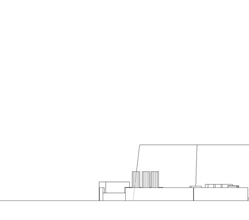
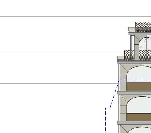
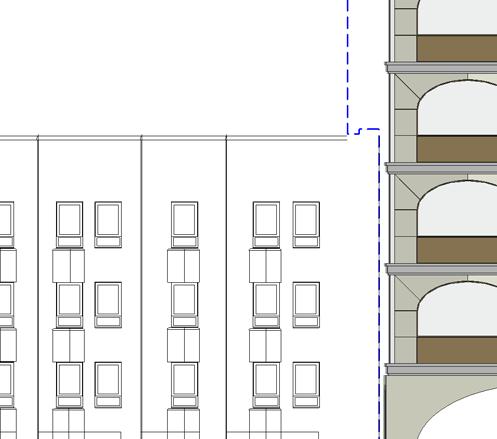
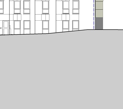
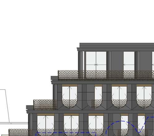
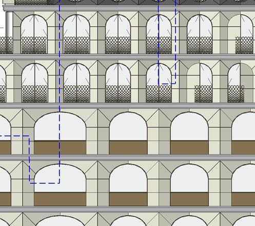
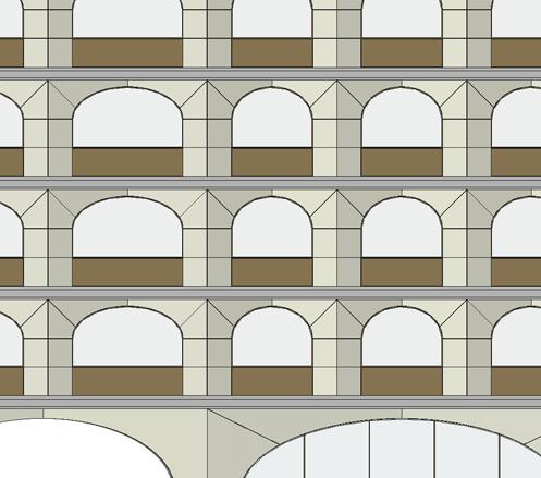
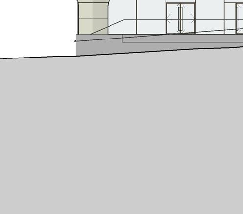
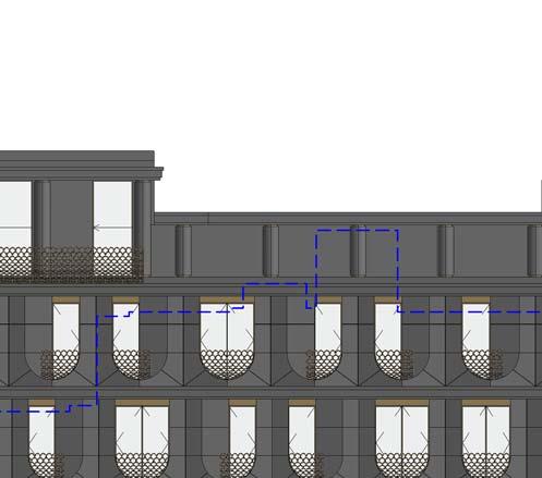
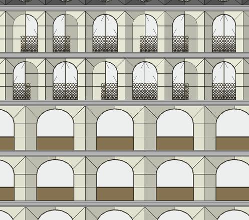
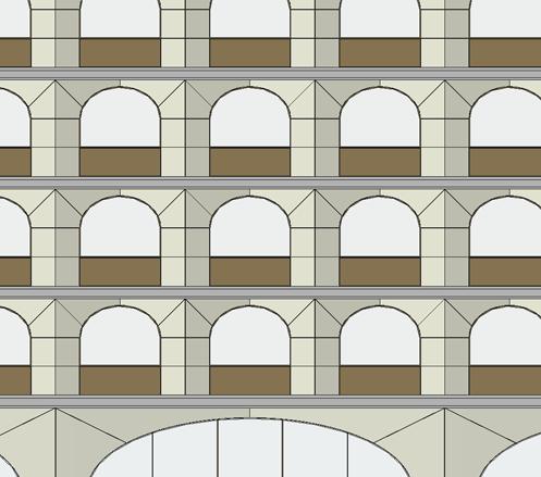
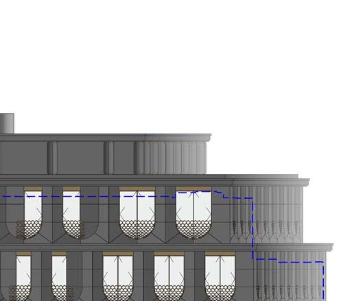
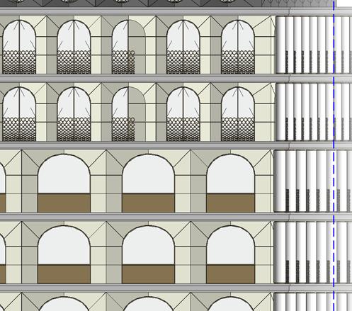
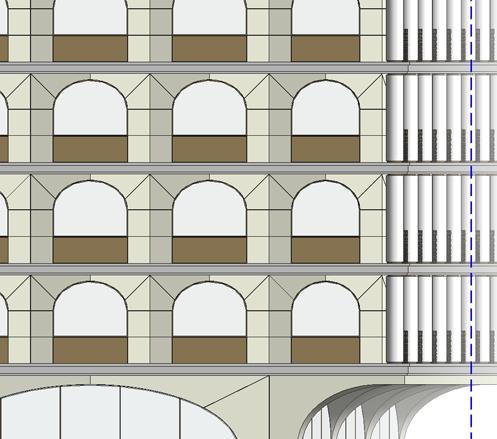


83 Craven Street Elevation Strand. Design and Access Statement. November 2016
Proposed
Fig.4.119
CRAVEN
Strand. Design and Access Statement. November 2016 th to 10th Floors:
STREET ELEVATION
same stone as the floors below
follow
same language arches and columns, however
proportion
change
the modulation creates both a small shift the alignment of the arches with regards to the floors below, and also provides smaller façade modules for the residential use and therefore helps to create a more flexible internal layout.
and
the
the
changes. This
in
ninth
tenth floors
same design principles of the front façade.
materiality changes to dark stone, and the geometry of the module changes to an inverted arch. Blind panels have been incorporated on the residential floors with dual purpose: to increase the environmental performance of the residential apartments and to increase the flexibility of the internal layouts. 1 3 4 1 Fig.4.129 Typical side section & elevation. 7 to 10 floors floors typical plan detail th th floors typical plan detail Indicative Material Key Stone cladding Bronze coloured metal cladding with embossed pattern Glazing unit in bronze colour frame. Bronze coloured decorative metal balustrade. Strand. Design and Access Statement. November 2016
and
follow the
The
4d 3d 5d 2d 1d 6d 1f
Fig.4.119 Proposed
CRAVEN
STREET ELEVATION
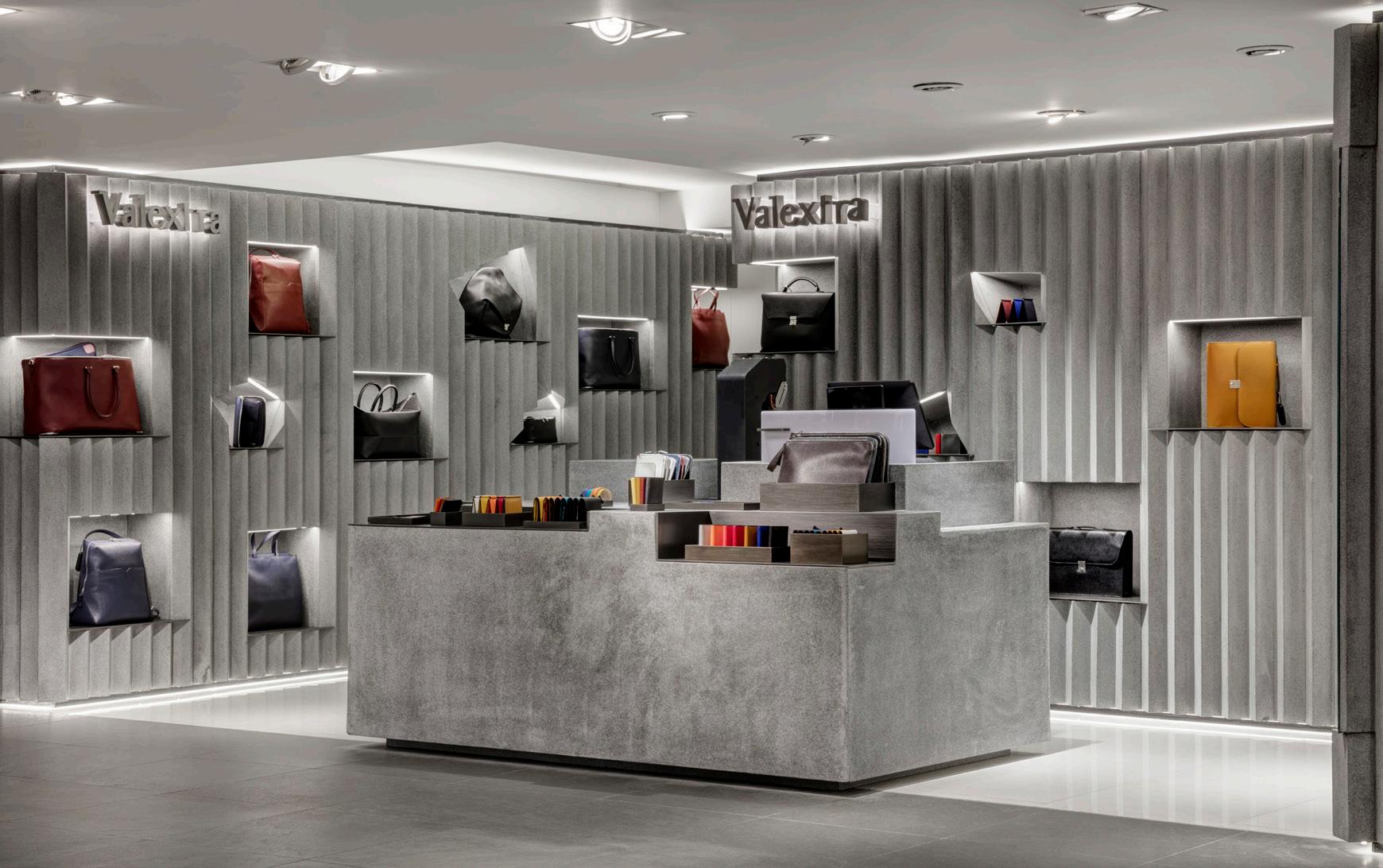
VALEXTRA
20m2 Instore Concession London, UK
RIBA Stages 1-6 2015
Resonating with the brand’s marriage of craft and innovation – the concept is a contemporary expression of timeless design and age-old techniques of fabrication. Valextra’s art of saddlery, attention to detail and passion for working with leather is very evident in the product and the space celebrates this quality.
The Valextra area is adjacent to a circulation route so the challenge was to create an environment that would encourage people to slow down and indulge themselves before moving to the next level. The project explores the use of glass reinforced concrete for the form and texture of the partitions. The effect is immediately arresting and immersive – it contrasts with much of the surrounding materiality of Harrods and presents a dramatic contemporary moment. While the crinkle cut concrete is a powerful statement, it is also refined and delicate – the structure is less than an inch thick. The freestanding bespoke pockets and cut-outs for the wallets and bags – frame and celebrate the products – almost like precious artefacts.
84


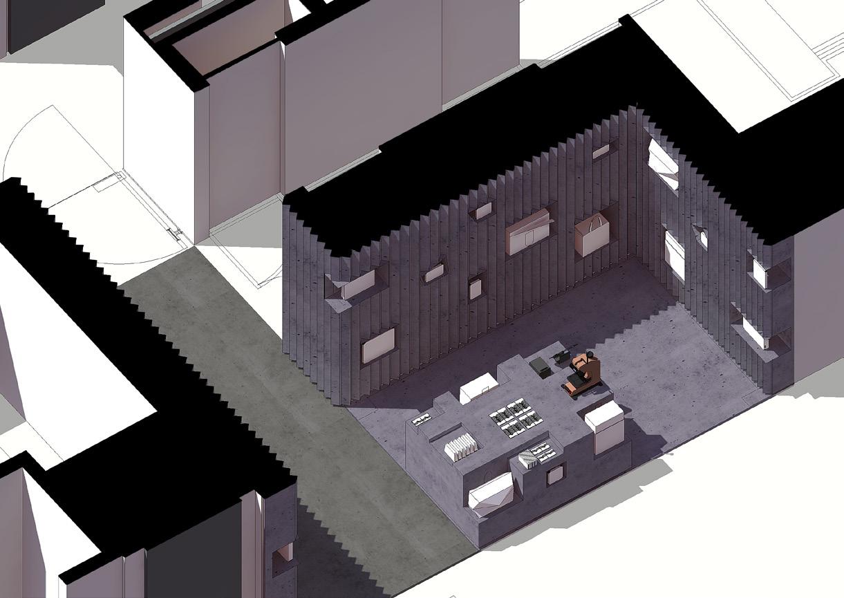
85 Valextra October 2015 LGF Proposed Plan Adjaye Associates Valextra - Shop / August 2015 Proposed Plan / 1:50 @ A3 012 5 350 1590 2000 4000 1290 1000 350 4900 530 350 700 1960 Plan View 1:50 1 2 1 4 2 3 1 1. Crinkle profile prefabricated GRC - (Glass Reinforced Concrete) 2. Niches to be formed in a smooth GRC Finish with integrated lighting above 3. Ryefast universal floor screed. Nominal 8 mm screed on 18 mm plywood substrate or similar approved 4. Smooth cast feature plinth with cut outs to provide display area for Valextra merchandising. (Items to be displayed TBC) 5. Perimeter lighting above precast panels at high and low level. Strip light TBC 6. Valextra backlit sign. Strip light TBC Valextra October 2015 LGF Proposed Elevations Adjaye Associates Valextra - Shop / August 2015 Proposed Plan / 1:50 @ A3 012 5 Front Elevation 1:50 1 Side Elevation 1:100 2 920 1480 2400 920 1480 2400 Adjaye Associates Valextra Shop / August 2015 Proposed Plan / 1:50 @ A3 012 5 Front Elevation 1:50 1 Side Elevation 1:100 2 920 1480 2400 920 1480 2400 Adjaye Associates Valextra Shop / August 2015 Proposed Plan / 1:50 @ A3 012 5 Front Elevation 1:50 1 Side Elevation 1:100 2 920 1480 2400 920 1480 2400 Adjaye Associates Valextra - Shop / August 2015 Proposed Plan / 1:50 @ A3 012 5 Front Elevation 1:50 1 Side Elevation 1:100 2 920 1480 2400 920 1480 2400 2 4 1 3 5 6 1. Crinkle profile prefabricated GRC - (Glass Reinforced Concrete) 2. Niches to be formed in a smooth GRC Finish with integrated lighting above 3. Ryefast universal floor screed. Nominal 8 mm screed on 18 mm plywood substrate or similar approved 4. Smooth cast feature plinth with cut outs to provide display area for Valextra merchandising. (Items to be displayed TBC) 5. Perimeter lighting above precast panels at high and low level. Strip light TBC 6. Valextra backlit sign. Strip light TBC Valextra / October 2015 LGF Proposed Elevations Valextra - Shop / August 2015 Proposed Plan / 1:50 @ A3 Elevation 1:50 Side Elevation 1:100 2 920 1480 2400 920 1480 2400 Adjaye Associates 012 Front Elevation 1:50 1 Adjaye Associates 012 Front 1:50 1 Valextra - Shop / August 2015 Proposed Plan / 1:50 @ A3 Front Elevation 1:50 1 Side Elevation 1:100 2 920 1480 2400 920 1480 2400 2 4 1 3 5 6 1. Crinkle profile prefabricated GRC - (Glass Reinforced Concrete) 2. Niches to be formed in a smooth GRC Finish with integrated lighting above 3. Ryefast universal floor screed. Nominal 8 mm screed on 18 mm plywood substrate or similar approved 4. Smooth cast feature plinth with cut outs to provide display area for Valextra merchandising. (Items to be displayed TBC) 5. Perimeter lighting above precast panels at high and low level. Strip light TBC 6. Valextra backlit sign. Strip light TBC Valextra October 2015 LGF Axo View Valextra October 2015 LGF Proposed Elevations Adjaye Associates Valextra Shop / August 2015 Proposed Plan / 1:50 @ A3 012 5 Front Elevation 1:50 1 Side Elevation 1:100 2 920 1480 2400 920 1480 2400 Adjaye Associates Valextra - Shop / August 2015 Proposed Plan / 1:50 @ A3 012 5 Front Elevation 1:50 1 Side Elevation 1:100 2 920 1480 2400 920 1480 2400 Adjaye Associates Valextra - Shop / August 2015 Proposed Plan / 1:50 @ A3 012 5 Front Elevation 1:50 1 Side Elevation 1:100 2 920 1480 2400 920 1480 2400 Adjaye Associates Valextra Shop / August 2015 Proposed Plan / 1:50 @ A3 012 5 Front Elevation 1:50 1 Side Elevation 1:100 2 920 1480 2400 920 1480 2400 2 4 1 3 5 6 1. Crinkle profile prefabricated GRC - (Glass Reinforced Concrete) 2. Niches to be formed in a smooth GRC Finish with integrated lighting above 3. Ryefast universal floor screed. Nominal 8 mm screed on 18 mm plywood substrate or similar approved 4. Smooth cast feature plinth with cut outs to provide display area for Valextra merchandising. (Items to be displayed TBC) 5. Perimeter lighting above precast panels at high and low level. Strip light TBC 6. Valextra backlit sign. Strip light TBC
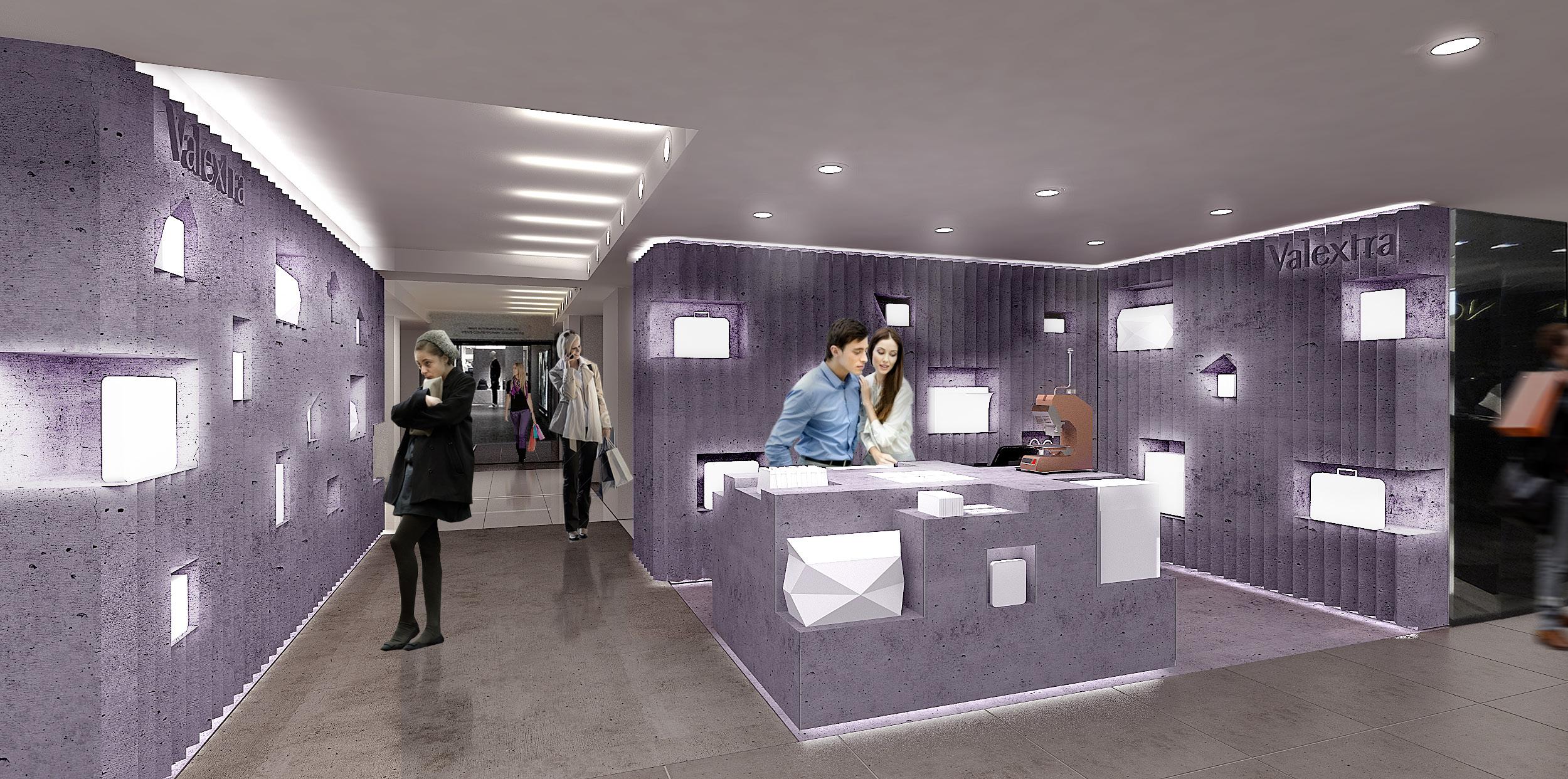
86 1280 GIFT WRAP COUNTER ,DIMENSIONS AS PER HARRODS.FINISHES TO MATCH WITH COUNTER 585 300 395 PLAN 1:20 1 ELEVATION -1 1:20 2 ELEVATION-2 1:20 3 ELEVATION-4 1:20 7 ELEVATION-3 1:20 6 E 11-002 MEK VG 29.10.15 1:20@ A3 COUNTER PLAN& ELEVATIONS VALEXTRA@HARRODS FOR COMMENT Date: DRAWING TO BE READ IN CONJUNCTION WITH THE SPECIFICATION AND ALL RELEVANT DRAWINGS DO NOT SCALE FROM THIS DRAWING CONTRACTOR TO CHECK ALL DIMENSIONS ON SITE ADJAYE/ASSOCIATES TO BE ADVISED OF ANY DISCREPANCIES BETWEEN THIS DRAWING AND SITE CONDITIONS IMMEDIATELY Checked by: Drawn by: Scale: Drawing No: Project: Drawing Title: 223-231 OLD MARYLEBONE ROAD LONDON NW1 5QT UNITED KINGDOM (0)20 (0)20 info@adjaye.com Adjaye Associates GIFT WRAP COUNTER ,DIMENSIONS AS PER HARRODS.FINISHES TO MATCH WITH COUNTER COUNTER CLAD WITH PIGMENTED GRC PANEL 119 870 70 800 50 920 170 700 50 GIFT COUNTER (SMALL ITEMS) COUNTER CLAD WITH PIGMENTED GRC PANEL 50 HIGH GRC SKIRTING 920 1039 70 800 870 50 TILL COUNTER IN ELEVATION 70 800 50 REV DATE COMMENTS A 30.10.2015 General Amendments B 06.11.2015 Modification in Counter Design VIEW- 01 NTS 4 C 10.11.2015 Modification in Counter Design as per Client's requirements VIEW-02 NTS 5 D 13.11.2015 Addition of drawers and removing one big bag area as per Client's requirements E 16.11.2015 Removal of drawers per Client's requirements 239 226 244 20MM PIGMENTED GRC SUSPENDED CEILING FLOORING(TBC) V4D22 SGL (V5A29) 338 1549 816 450 292 172 500 (V4A32) 500 440 (V5D27) 489 400 550 400 338 1549 851 2400 385 SGL ELEVATION 3 1:25 1 ELEVATION 4 1:25 2 E 12-002 MEK VG 29.10.15 1:25@ A3 ELEVATION 3&4 VALEXTRA@HARRODS FOR COMMENT Date: DRAWING TO BE READ IN CONJUNCTION WITH THE SPECIFICATION AND ALL RELEVANT DRAWINGS CONTRACTOR TO CHECK DIMENSIONS ON SITE ADJAYE/ASSOCIATES TO ADVISED OF ANY DISCREPANCIES BETWEEN THIS DRAWING AND SITE CONDITIONS IMMEDIATELY Checked by: Drawn by: Scale: Drawing Project: Drawing 223-231 OLD MARYLEBONE ROAD LONDON NW1 UNITED KINGDOM (0)20 7258 6140 (0)20 7258 6148 info@adjaye.com Adjaye Associates BUSINESS BUSINESS REV DATE A 30.10.2015 General Amendments B 04.11.2015Changes in Display client's requirements C 06.11.2015Changes in Display as per client's requirements NOTES BAGS FROM TRAVEL (OPTIONAL) D 10.11.2015Changes in Display as per client's requirements PLAN 1:25 3 PLAN 1:25 4 E 16.11.2015Minor Amendments following Contractor's Meeting Valextra October 2015 LGF Visualization
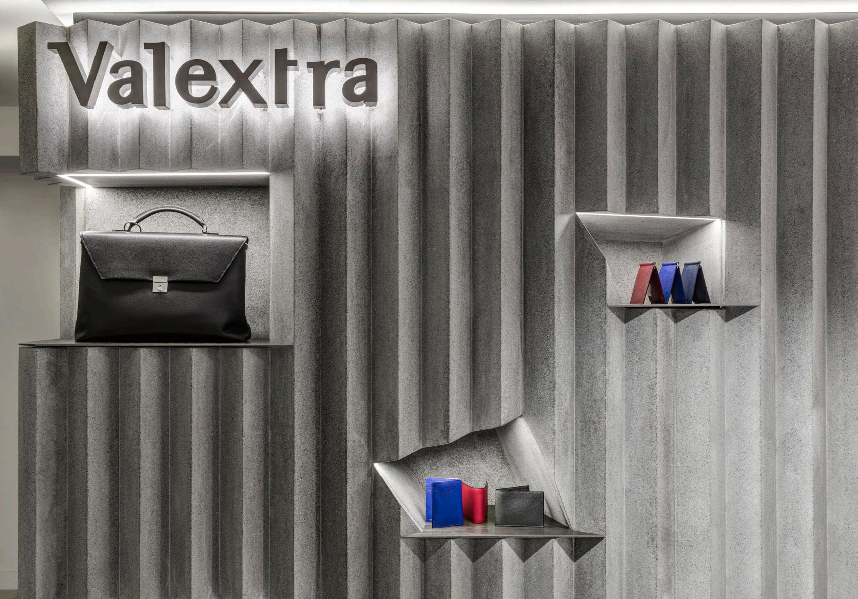
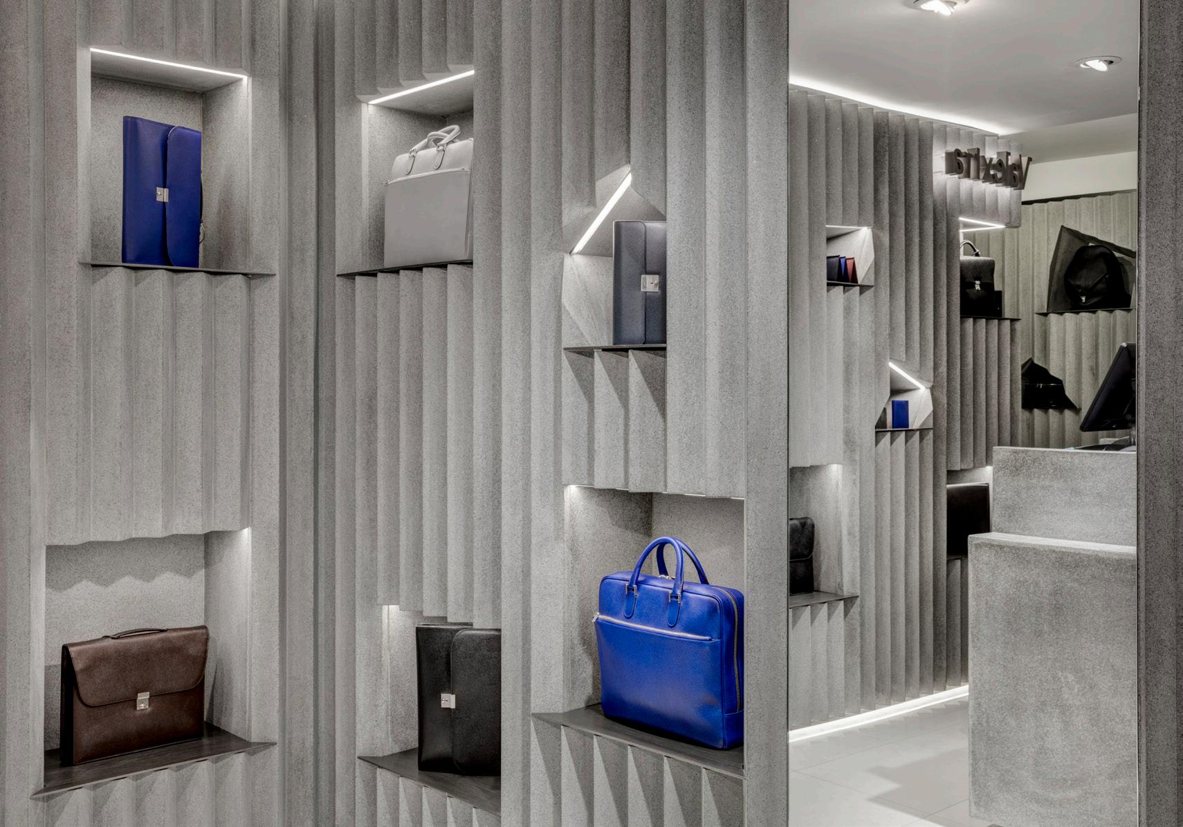
87
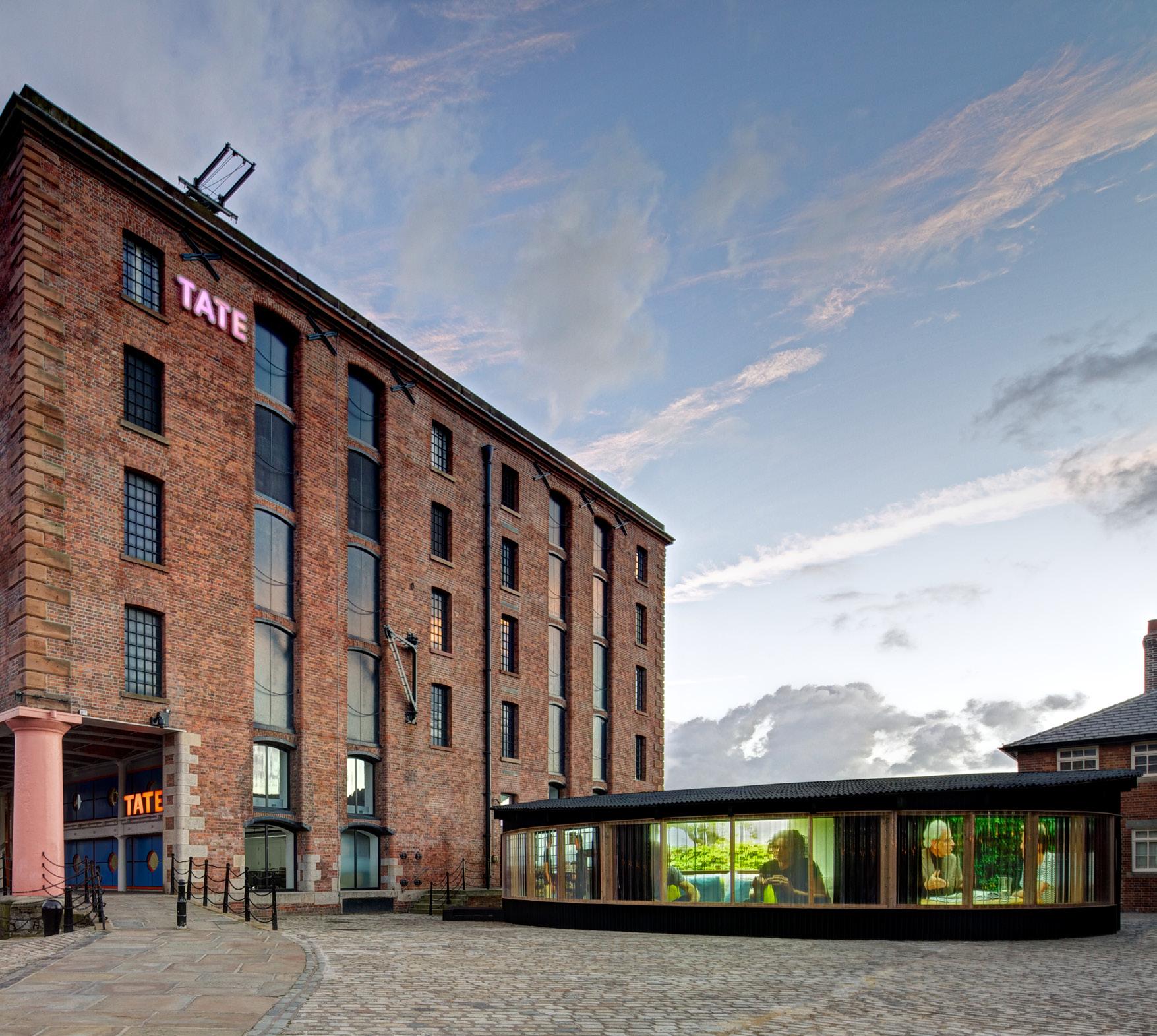
160m2 Temporary pavilion Liverpool, UK
RIBA Stages 1-6 2014
A collaboration with Doug Aitken, The Source is a temporary structure that was housed on Liverpool’s historic Albert Dock, as part of the Liverpool Biennial 2012/13. The project is an immersive installation comprising a series of filmed conversations about creativity between Aitken and some of the world’s most established creative individuals. The temporary structure is a deliberate device to separate the work from the traditional gallery space and to create a new cultural territory. The collage of imagery and interviews radiate within a diorama – a cylindrical chamber – inside which six projections are simultaneously displayed in six little rooms. As visitors cross the bridge over to Tate Liverpool, the structure is almost unavoidable. Although the projections are on the inside, they have a ghost image on the exterior – especially at night to attract people inside.
88
LIVERPOOL BIENNIAL
89 2800 LEGEND 01- CLEAR CORRUGATED POLYCARBONATE 02- BITUMEN CORRUGATED BOARD NORTH ELEVATION Scale: 1:100 1 SOUTH ELEVATION Scale: 1:100 2 02 01 4.60 m 2.80 0.20 m 4.60 m 2.80 0.20 m 2800 02 01 E 12-101 YB EAR 24.08.12 1:100/1:50@A3 NORTH / SOUTH ELEVATION DOUG AITKEN PAVILION INFORMATION Date: DRAWING TO BE READ IN CONJUNCTION WITH THE SPECIFICATION AND ALL RELEVANT DRAWINGS DO NOT SCALE FROM THIS DRAWING CONTRACTOR TO CHECK ALL DIMENSIONS ON SITE ADJAYE/ASSOCIATES TO BE ADVISED OF ANY DISCREPANCIES BETWEEN THIS DRAWING AND SITE CONDITIONS IMMEDIATELY Checked by: Revision: Drawn by: Scale: Drawing No: Project: Drawing Title: 223-231 OLD MARYLEBONE ROAD LONDON NW1 5QT UNITED KINGDOM TEL: +44 (0)20 7258 6140 FAX: +44 (0)20 7258 6148 info@adjaye.com Adjaye Associates REV DATE COMMENTS - 17.05.12 PLANNING A 29.06.12 ISSUED FOR INFORMATION B 17.07.12 ISSUED FOR INFORMATION C 25.07.12 ISSUED FOR INFORMATION D 16.08.12 ISSUED FOR INFORMATION E 24.08.12 ISSUED FOR INFORMATION LEGEND 01- CLEAR CORRUGATED POLYCARBONATE 02- BITUMEN CORRUGATED BOARD WEST ELEVATION Scale: 1:100 2 EAST ELEVATION Scale: 1:100 1 01 02 02 4.60 m 2.80 m 0.20 m 4.60 m 2.80 0.20 m 01 02 E 12-102 YB EAR 24.08.12 1:100/1:50@A3 EAST WEST ELEVATION DOUG AITKEN PAVILION INFORMATION Date: DRAWING TO BE READ IN CONJUNCTION WITH THE SPECIFICATION AND ALL RELEVANT DRAWINGS DO NOT SCALE FROM THIS DRAWING CONTRACTOR TO CHECK ALL DIMENSIONS ON SITE ADJAYE/ASSOCIATES TO BE ADVISED OF ANY DISCREPANCIES BETWEEN THIS DRAWING AND SITE CONDITIONS IMMEDIATELY Checked by: Revision: Drawn by: Scale: Drawing No: Project: Drawing Title: 223-231 OLD MARYLEBONE ROAD LONDON NW1 5QT UNITED KINGDOM (0)20 (0)20 info@adjaye.com Adjaye Associates REV DATE COMMENTS - 17.05.12 PLANNING A 29.06.12 ISSUED FOR INFORMATION B 17.07.12 ISSUED FOR INFORMATION C 25.07.12 ISSUED FOR INFORMATION D 16.08.12 ISSUED FOR INFORMATION E 24.08.12 ISSUED FOR INFORMATION SECTION AA Scale: 1:50 1 0.22 m 2.80 m m E 13-101 YB EAR 24.08.12 1:100/1:50@A3 SECTION DOUG AITKEN PAVILION INFORMATION Date: DRAWING TO BE READ IN CONJUNCTION WITH THE ADJAYE/ASSOCIATES TO BE ADVISED OF ANY DISCREPANCIES by: by: Scale: Drawing Project: Drawing Title: 223-231 OLD MARYLEBONE ROAD LONDON NW1 5QT UNITED KINGDOM TEL: +44 (0)20 7258 6140 FAX: +44 (0)20 7258 6148 info@adjaye.com Adjaye Associates - 17.05.12 PLANNING 29.06.12 ISSUED FOR INFORMATION C 25.07.12 ISSUED FOR INFORMATION D 16.08.12 ISSUED FOR INFORMATION TATE LIVERPOOL N LOW LEVEL PLAN Scale: 1:100 1 1 23 4 45.00° 45.00° 45.00° 1 2 3 4 01-003B 12-102 A E 11-101 YB EAR 24.08.12 1:100@A3 GROUND FLOOR PLAN DOUG AITKEN PAVILION INFORMATION Date: DRAWING TO BE READ IN CONJUNCTION WITH THE SPECIFICATION AND ALL RELEVANT DRAWINGS DO NOT SCALE FROM THIS DRAWING CONTRACTOR TO CHECK ALL DIMENSIONS ON SITE ADJAYE/ASSOCIATES TO BE ADVISED OF ANY DISCREPANCIES BETWEEN THIS DRAWING AND SITE CONDITIONS IMMEDIATELY Checked by: Drawn by: Scale: Drawing No: Project: Drawing Title: OLD MARYLEBONE ROAD LONDON NW1 UNITED KINGDOM TEL: +44 (0)20 7258 6140 FAX: +44 (0)20 7258 6148 info@adjaye.com Adjaye Associates REV DATE COMMENTS - 17.05.12 PLANNING A 29.06.12 ISSUED FOR INFORMATION B 17.07.12 ISSUED FOR INFORMATION C 25.07.12 ISSUED FOR INFORMATION D 16.08.12 ISSUED FOR INFORMATION E 24.08.12 ISSUED FOR INFORMATION
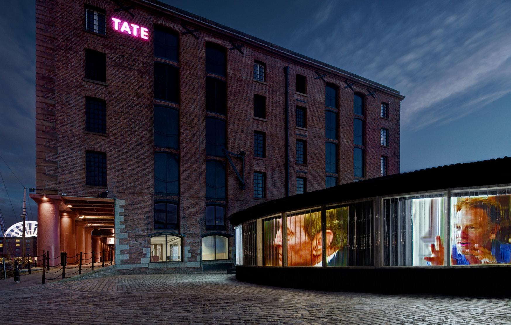
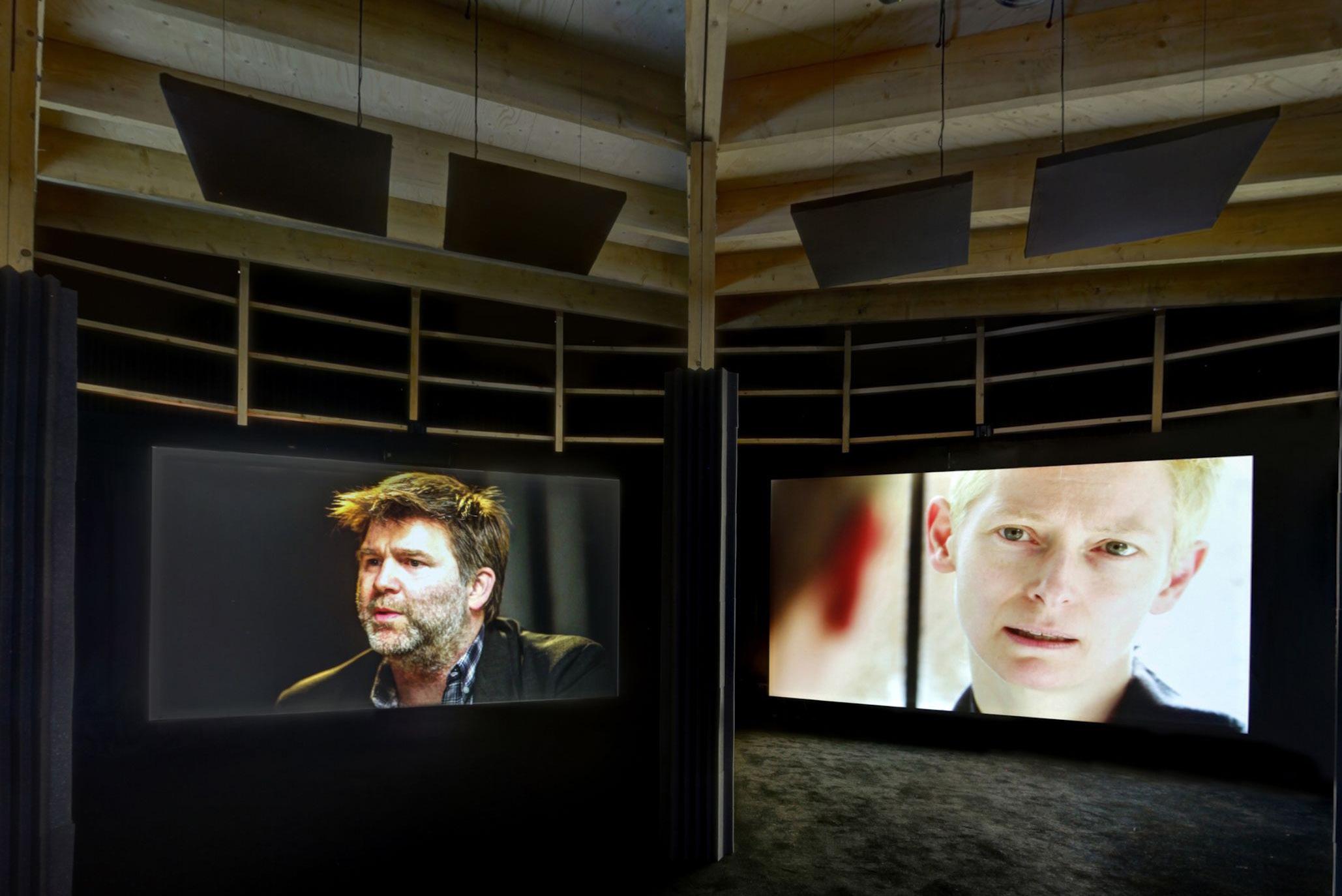
90
91 200 FFL = +0.22 100 Varies 455 200 EXISTING COBBLED GROUND MASTIC JOINT CORRUGATED BITUMINEN BOARD MASTIC JOINT 200X75MM HORIZONTAL TIMBER CLADDING RAILS BETWEEN VERTICAL MEMBERS. TRANSPARENT CORRUGATED POLYCARBONATE PROJECTION FABRIC SCREEN VERTICAL TIMBER SUPPORT TBC BY STRUCTURAL ENGINEER TRANSPARENT CORRUGATED POLYCARBONATE CORRUGATED BITUMINEN BOARD TIMBER PLINTH PAINTED PLYWOOD 1 14-102 75X75MM TIMBER STUD TO MATCH MDF MDF PANEL TH.20 MM TO FIX CURTAIN TRACK AND SCREEN PROJECTOR CORD OPERTAED CURTAIN TRACK SYSTEM (SILENT GLISS 6200) PROJECTION SCREEN WITH FRAME (TYPICO MEGAPRINTS GMBH & CO) 75 75 200 220 320 1 14-102 1 14-103 1 14-103 75X75MM TIMBER STUDS TO PROVIDE SUPPORT TO CURTAIN TRACK AT 400 MM CENTERS. REFER TO SECTION C 14-102 TENSION CABLE TBC BY STRUCTURAL ENGINEER 400 1920 2025 2345 Varies FALLS BLACK BITUMINEN BOARD ON COUNTER BATTENS ON TIMBER BATTENS ON WATERPROOFING LAYER ON 18MM DOUGLAS FIR PLYWOOD Drawing Title: Project: Drawing No: Scale: Drawn by: Revision: Checked by: DRAWING TO BE READ IN CONJUNCTION WITH THE SPECIFICATION AND ALL RELEVANT DRAWINGS DO NOT SCALE FROM THIS DRAWING CONTRACTOR TO CHECK ALL DIMENSIONS ON SITE ADJAYE/ASSOCIATES TO BE ADVISED OF ANY DISCREPANCIES BETWEEN THIS DRAWING AND SITE CONDITIONS IMMEDIATELY Date: INFORMATION DOUG AITKEN PAVILION TYPICAL DETAIL SECTION 1:10 @ A3 13.08.12 EAR YB 14-101Rev Date Comments NOTE: ALL TIMBERS TO RECEIVE TERMITE PROTECTION. SPEC TBC. CONTRACTOR TO ADVISE ALL STEEL TO RECEIVE TWO COATS OF A GOOD QUALITY SOLVANT BASED ANTI-CORROSION PRIMER AND PAINT. TEL: +44 (0)20 7258 6140 FAX: +44 (0)20 7258 6148 info@adjaye.com Adjaye Associates - 17.07.12 ISSUED FOR INFORMATION 3 TIMBER STUD 200mm x 50mm ROOF BEAM ABOVE PLINTH EDGE BELOW 75X75mm TIMBER STUD TO MATCH MDF STEEL TENSION CABLE TO BE ADVISED BY STRUCTURAL ENGINEER 1 14-101 1 14-101 TRANSPARENT CORRUGATED POLYCARBONATE ROOF STUD ABOVE ROOF EDGE ABOVE 200X50mm HORIZONTAL TIMBER CLADDING RAILS BETWEEN VERTICAL MEMBERS. ACOUSTIC FOAM PANEL 75 mm THICK Drawing Project: Drawing No: Scale: by: Revision: Checked by: DRAWING TO CONJUNCTION DO NOT SCALE FROM THIS DRAWING CONTRACTOR TO CHECK ALL DIMENSIONS ON SITE ADJAYE/ASSOCIATES TO BE ADVISED OF ANY DISCREPANCIES BETWEEN THIS DRAWING AND SITE CONDITIONS IMMEDIATELY Date: INFORMATION DOUG AITKEN PAVILION TYPICAL LOW LEVEL PLAN DETAIL 1:10 @ A3 13.08.12 EAR YB 14-102Rev Date Comments NOTE: ALL TIMBERS TO RECEIVE TERMITE PROTECTION. SPEC TBC. CONTRACTOR TO ADVISE ALL STEEL TO RECEIVE TWO COATS OF A GOOD QUALITY SOLVANT BASED ANTI-CORROSION PRIMER AND PAINT. 223-231 OLD MARYLEBONE ROAD LONDON NW1 KINGDOM (0)20 7258 6140 (0)20 7258 6148 info@adjaye.com Adjaye Associates - 17.07.12 ISSUED DOR INFORMATION
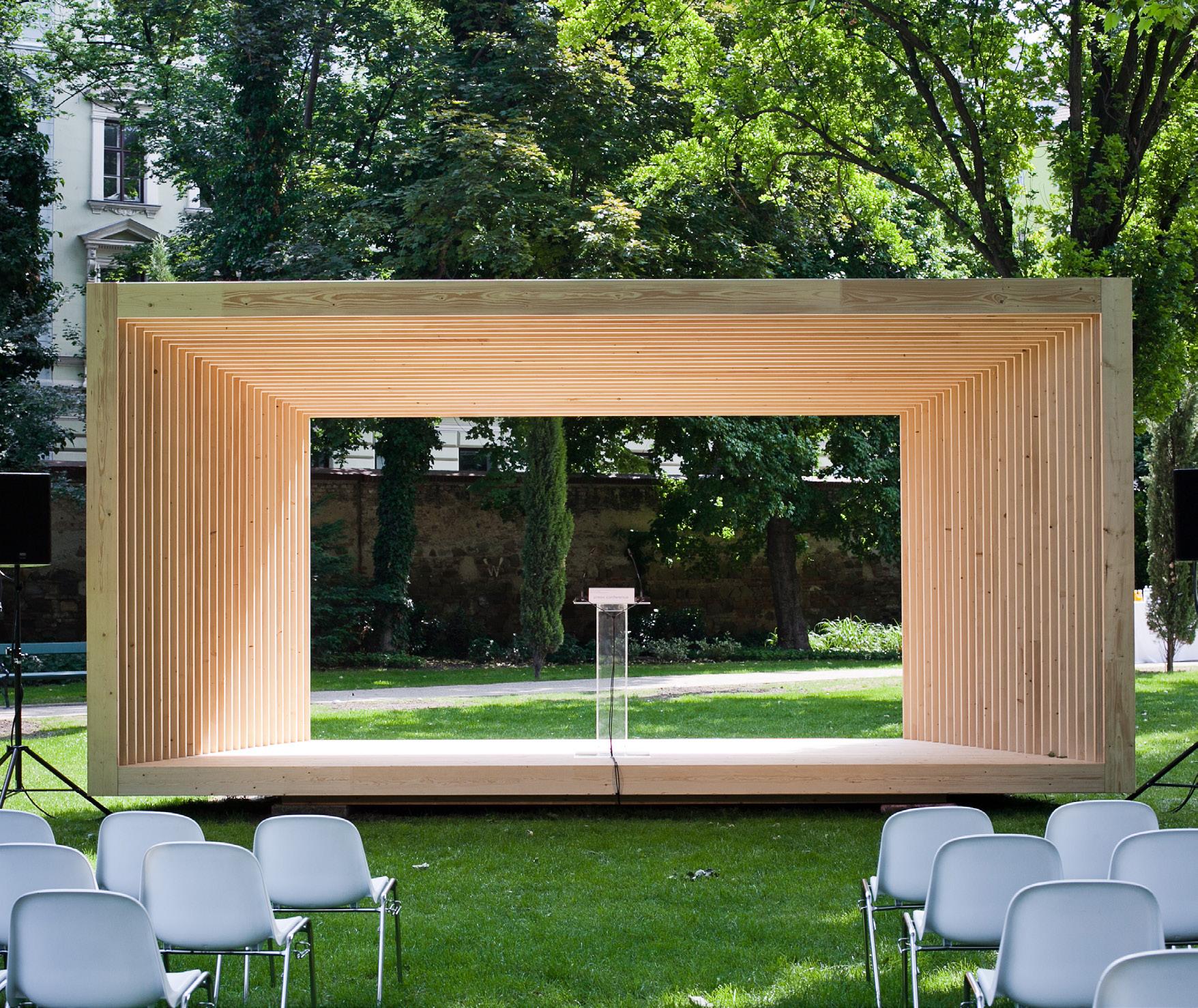
EPHEMEROPTERAE PAVILION
VIENNA
2.5X6.7m Temporary Pavilion
Vienna, Austria
RIBA Stages 1-6
2012
The pavilion is a trapezoid prism measuring 2.5 x 6.7m at its widest point. It is a portal frame where each frame forms the roof, flooring and walls. These structural elements work together and through compression, provide the overall structure of the pavilion. The height varies from 3 to 3.5m, rising up as the pavilion widens framing the view of the surrounding park. The pavilion is a free standing structure which will rest on a series of pad foundations and larch sleepers, intending minimise disruption to the parkland. Gaps between the timber slats to allow natural daylight and ventilation into the structure whilst the roof is solid to provide shelter.
Made from spruce, the pavilion is stained to increase longevity and allowing the timbers to turn silver grey over time. The modular sections will arrive in Vienna, pre-treated and pre-assembled, to ensure a high quality and swift installation. The timber structure will include all the necessary fixings including bolts and other metal members to give it additional strength. All structural metal frames will be hidden within the timber structure and will not be visible
92
93 4760 2550 6670 4 3 A A 7258 6148, Info@adjaye.com VIENNA PAVILION APRIL 2012 PLAN / SECTION SCALE 1:50@A3 2 1 TIMBER FRAMES 200X50MM CEILING: TIMBER FRAMES 40X50MM CEILING: TIMBER FRAMES 240X50MM FLOORING: TIMBER FRAMES 200X50MM FLOORING: TIMBER FRAMES 100X50MM 2 SECTION AA Scale: 1:50 1 PLAN Scale: 1:50 CONCRETE PLINTH (HIGH TBC) WITH ANTI TERMITE TREATMENT( TO BE CONFIRMED BY STRUCTURAL ENGINEERS) 0.00m 3.24 m 3.00m 0.00m 2.74 m 2.50m 240 2500 200 TBC 240 3000 200 TBC 4760 2550 6670 4 3 A A 7258 6148, Info@adjaye.com VIENNA PAVILION APRIL 2012 PLAN / SECTION SCALE 1:50@A3 2 1 TIMBER FRAMES 200X50MM CEILING: TIMBER FRAMES 40X50MM CEILING: TIMBER FRAMES 240X50MM FLOORING: TIMBER FRAMES 200X50MM FLOORING: TIMBER FRAMES 100X50MM 2 SECTION AA Scale: 1:50 1 PLAN Scale: 1:50 CONCRETE PLINTH (HIGH TBC) WITH ANTI TERMITE TREATMENT( TO BE CONFIRMED BY STRUCTURAL ENGINEERS) 0.00m 3.24 m 3.00m 0.00m 2.74 m 2.50m 240 2500 200 TBC 240 3000 200 TBC
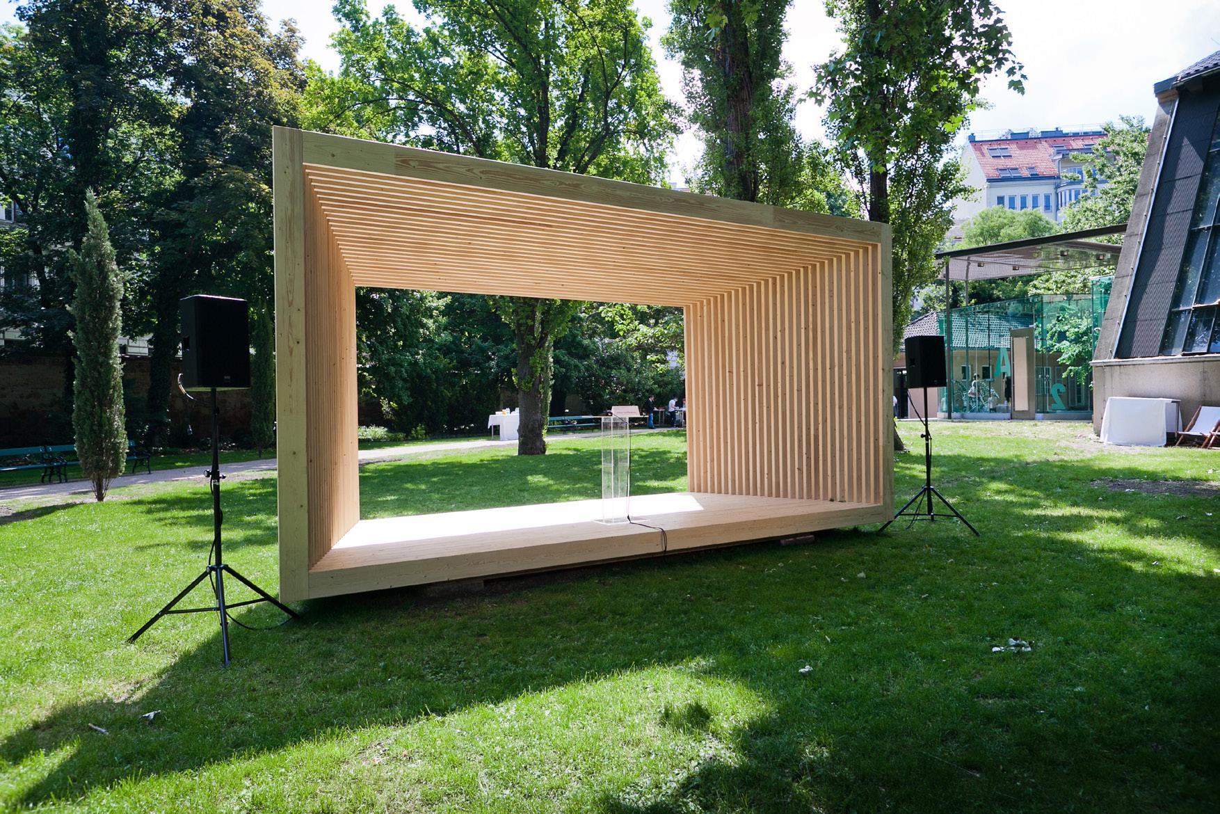
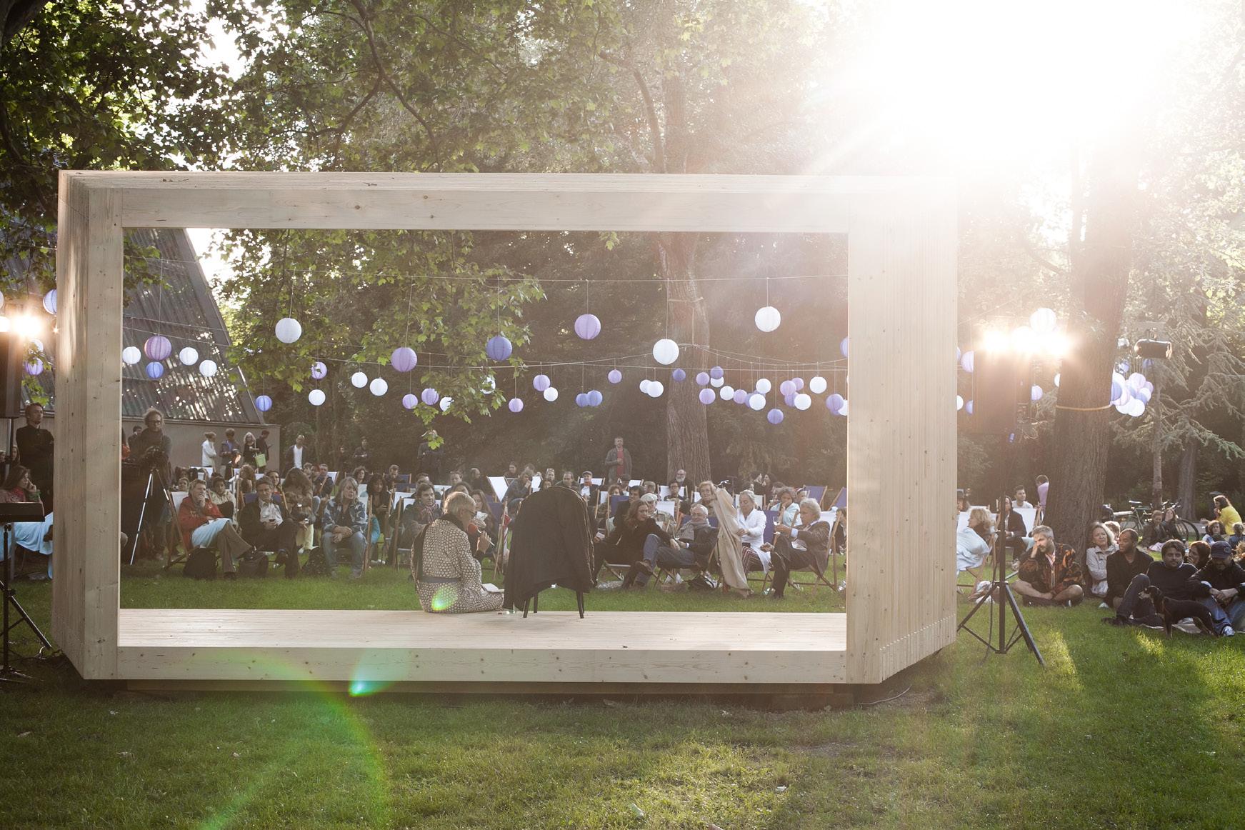
94
95 The Edison, 223-231 Old Marylebone Rd, NW1 5QT Tel. +44 20 7258 6140, Fax. +44 20 7258 6148, Info@adjaye.com ADJAYE ASSOCIATES VIENNA PAVILION 2 ELEVATION 2 Scale: 1:50 0.00m 2.74 m 2.50m 1 ELEVATION 1 Scale: 1:50 3 ELEVATION 3 Scale: 1:50 4 ELEVATION 4 Scale: 1:50 240 2500 200 TBC 0.00m 3.24 m 3.00m 2.50m 0.00m 3.24 m 3.00m Info@adjaye.com VIENNA PAVILION APRIL 2012 ELEVATIONS SCALE 1:50@A3 0.00m 3.24 m 3.00m 0.00m 2.74 m 2.50m 240 2500 200 TBC 240 3000 200 TBC 3 ELEVATION 3 Scale: 1:50 4 ELEVATION 4 Scale: 1:50 240 2500 200 TBC 240 3000 200 TBC 0.00m 3.24 m 3.00m 0.00m 2.74 m 2.50m
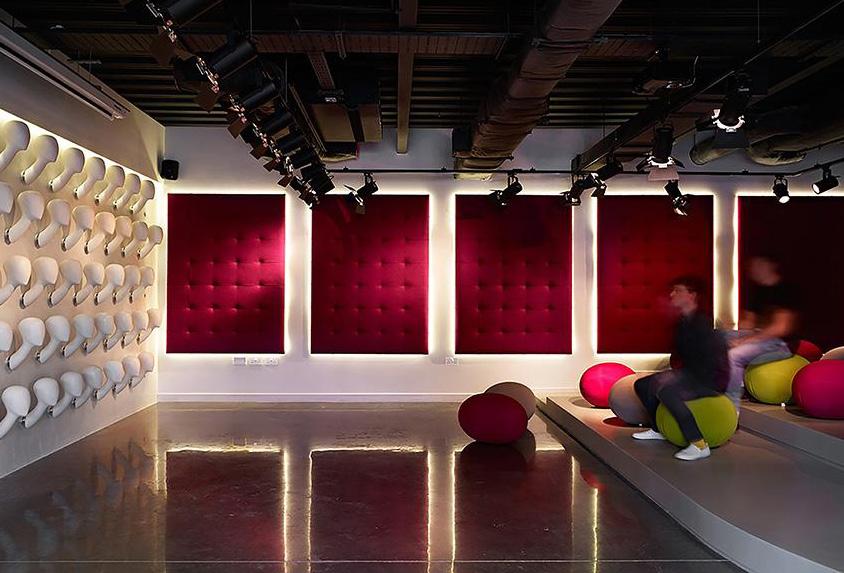
FEME LONDON HEADQUARTERS
950m2 Corporate Headquarters London, UK
RIBA Stages 1 - 6 2010
Feme opened in the UK in 1998 distributing high quality hairpieces, braids, weaves, extensions, accessories and designer wigs to a growing professional market in the UK and Europe.
After ten years of growth, Feme embarked on a strategy to consolidate their position by relocating to larger premises. The move brought together their showrooms, office operations, marketing studios and warehouses in London under one roof. With office facilities covering 10,000 square feet over two floors, the building provided an opportunity to create an environment to express Feme’s brand values, stimulating innovation and leadership in their market sector
The brief asked to rebrand a beauty company and convert a newly built office block into their Head quarters, with an original and functional design. The full makeover included concepts such as: a personlised wall of heads, handstitched fabric lighting boards, a 35m long precast concrete resin catwalk that doubles as a banquet table, a timber slatted feature wall back pinned with pink velvet.
96
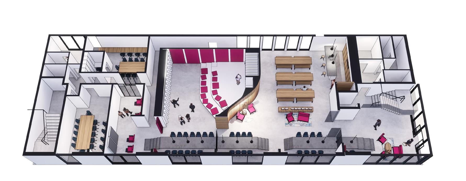
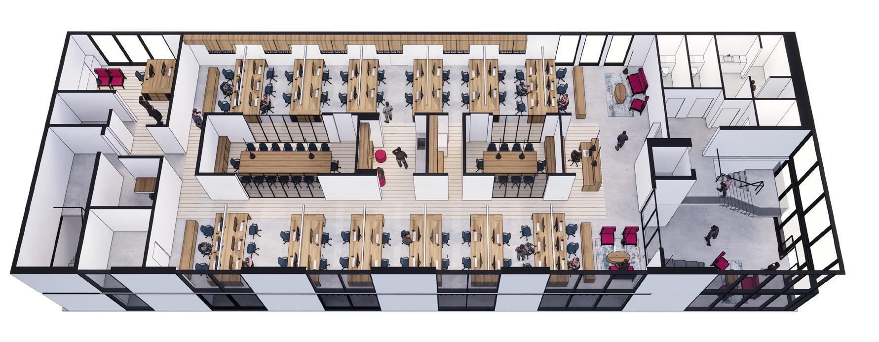
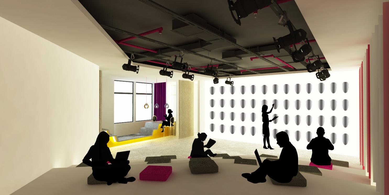
97
3D VIEW - Exhibition Space /Lightbox wall /Catwalk
Concept Drawings

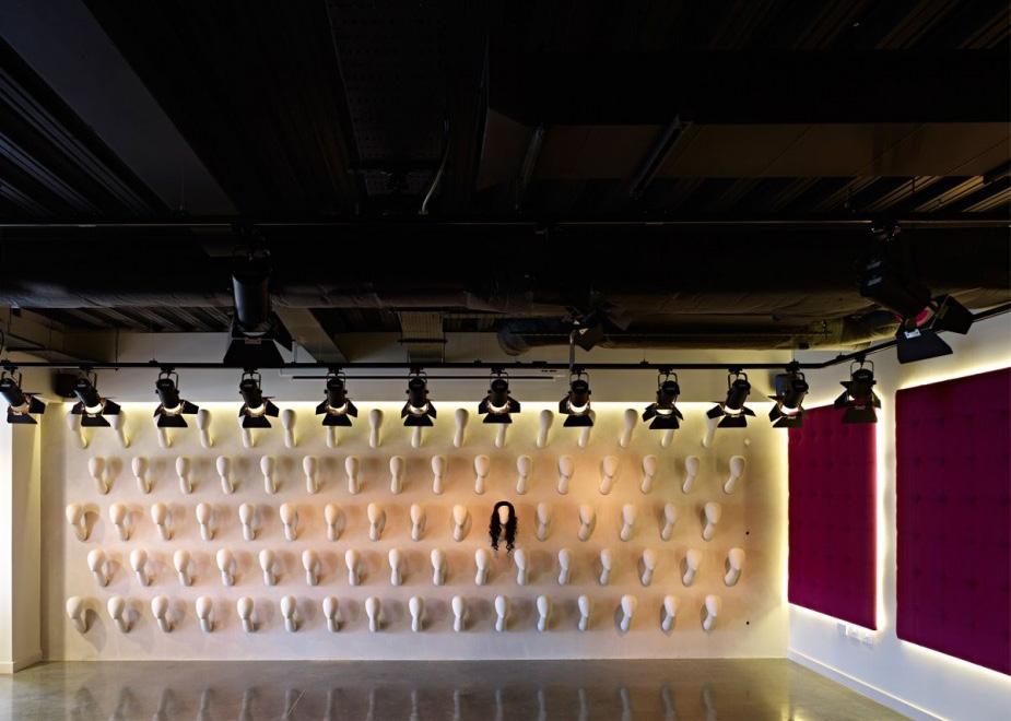
98
99
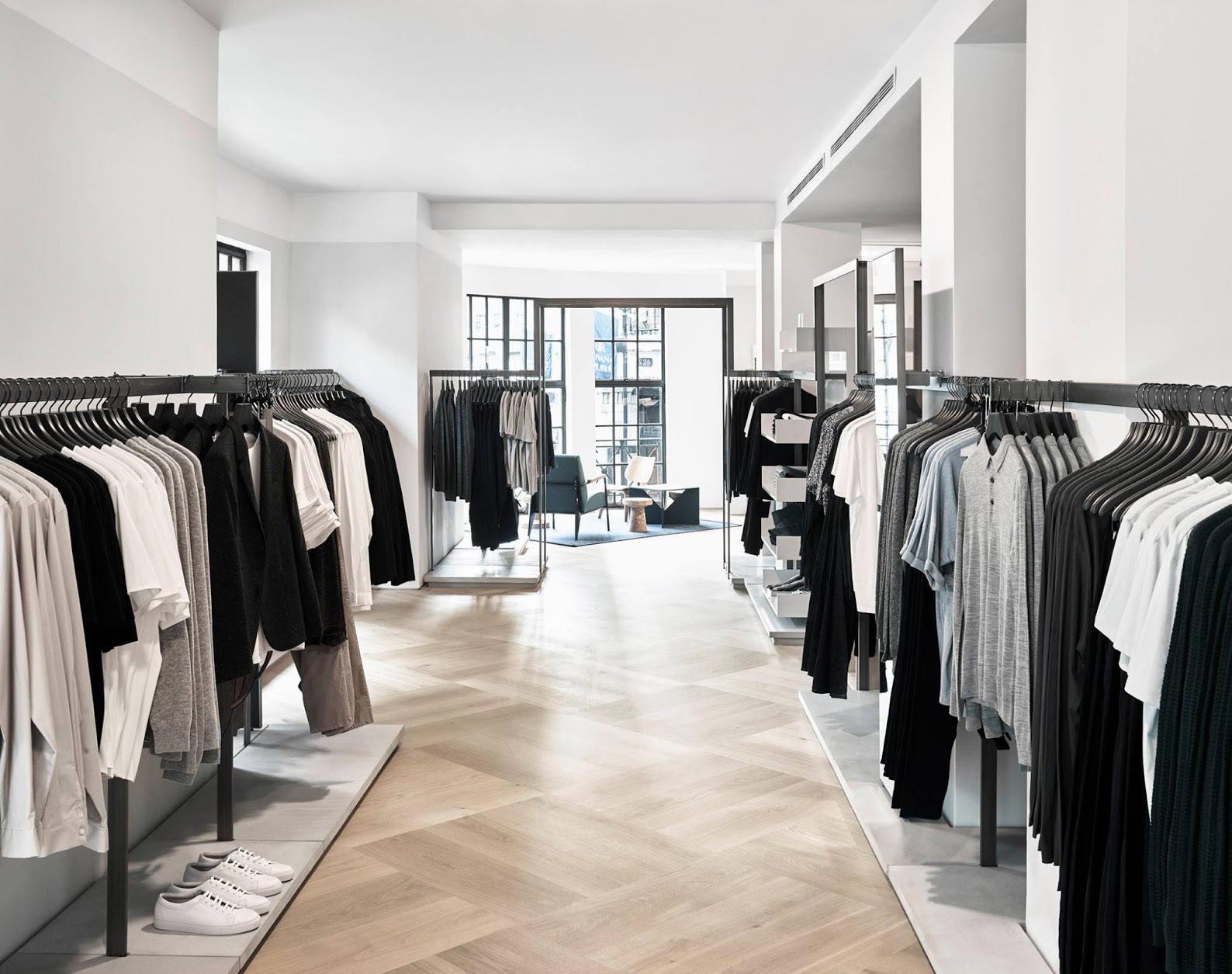
COS STORES EUROPE
Cos Stores Frankfurt, Barcelona, Milan, London London, UK
RIBA Stages 1- 6 2009
COS launched its flagship store on London’s Regent Street in March 2007 with a catwalk show at the Royal Academy Its concept is encompassed by minimalist style inspired by architecture, graphics, and design. It specialises in modern clothing pieces for men and women that are less trend-oriented than other similarly priced labels. The brand has used all aspects of design to build its reputation, following the principles of “timeless, modern, functional and tactile” for its garments, store interiors, graphics and packaging – all of which are currently designed in-house.
COS is a fashion brand for women and men who want modern, functional, considered design. Offering reinvented classics and wardrobe essentials, COS creates pieces that are made to last beyond the season. Traditional methods and new techniques merge to form timeless, understated collections. Since launching in 2007, they have opened stores worldwide in carefully considered locations, applying an architectural design concept that preserves buildings’ original features whilst creating a modern, welcoming space.
100
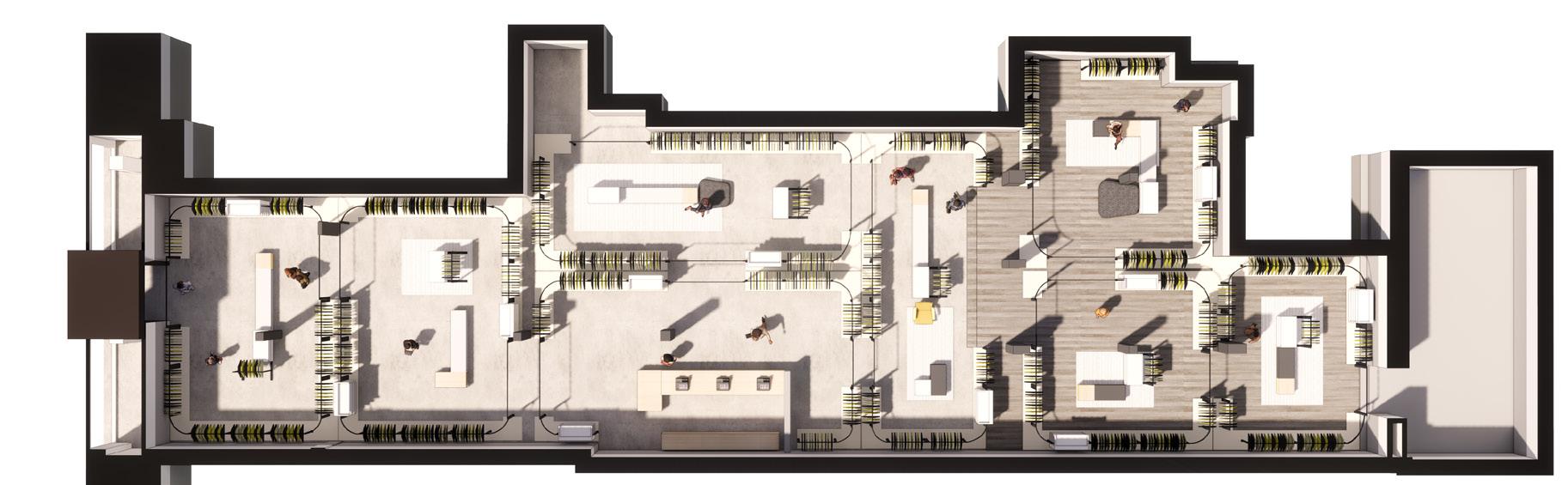
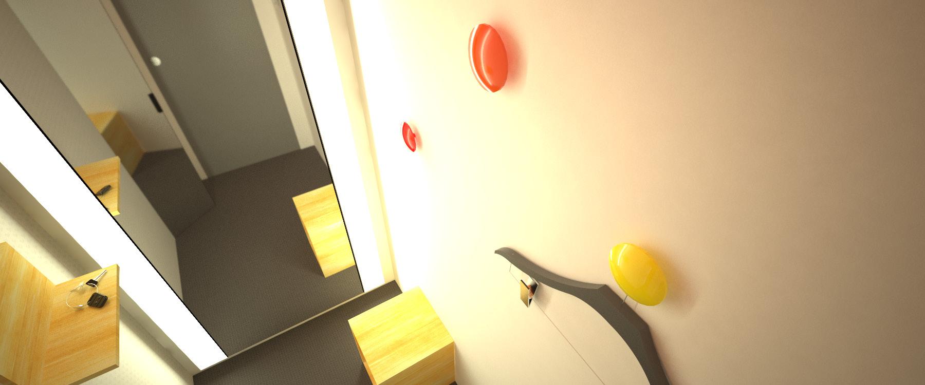
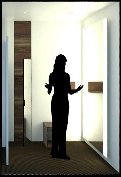
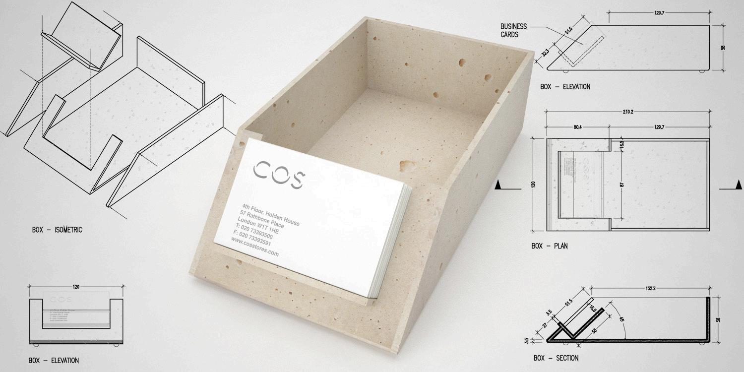
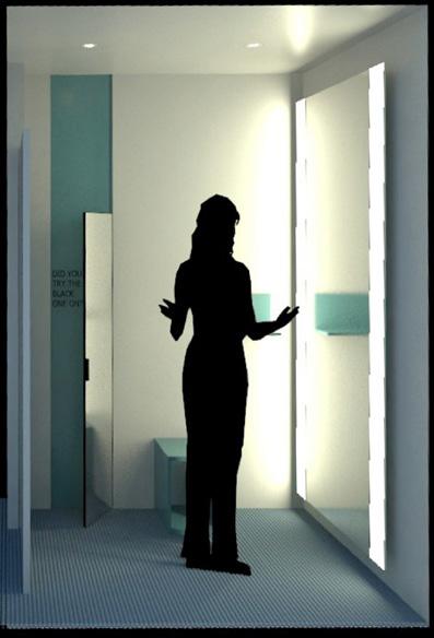
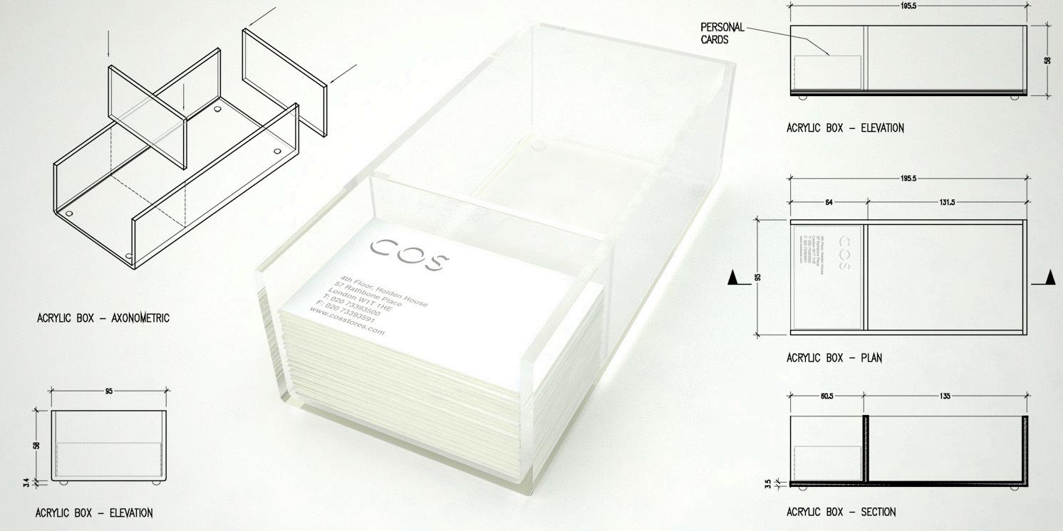
101

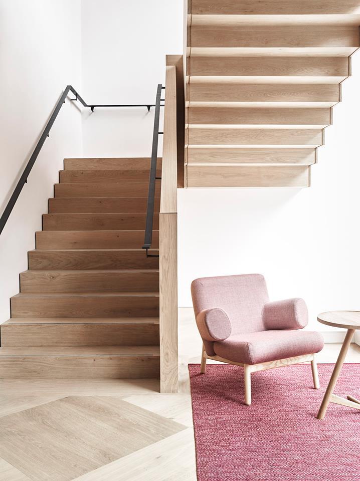
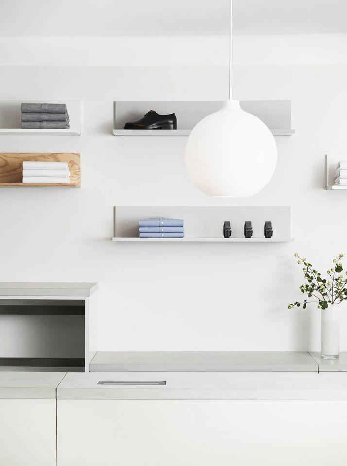
102
103
SANTIAGO CALA +44 07706170716 santicala@mail.com www.santiagocala.com
