05
INTERPRETATION CENTRE
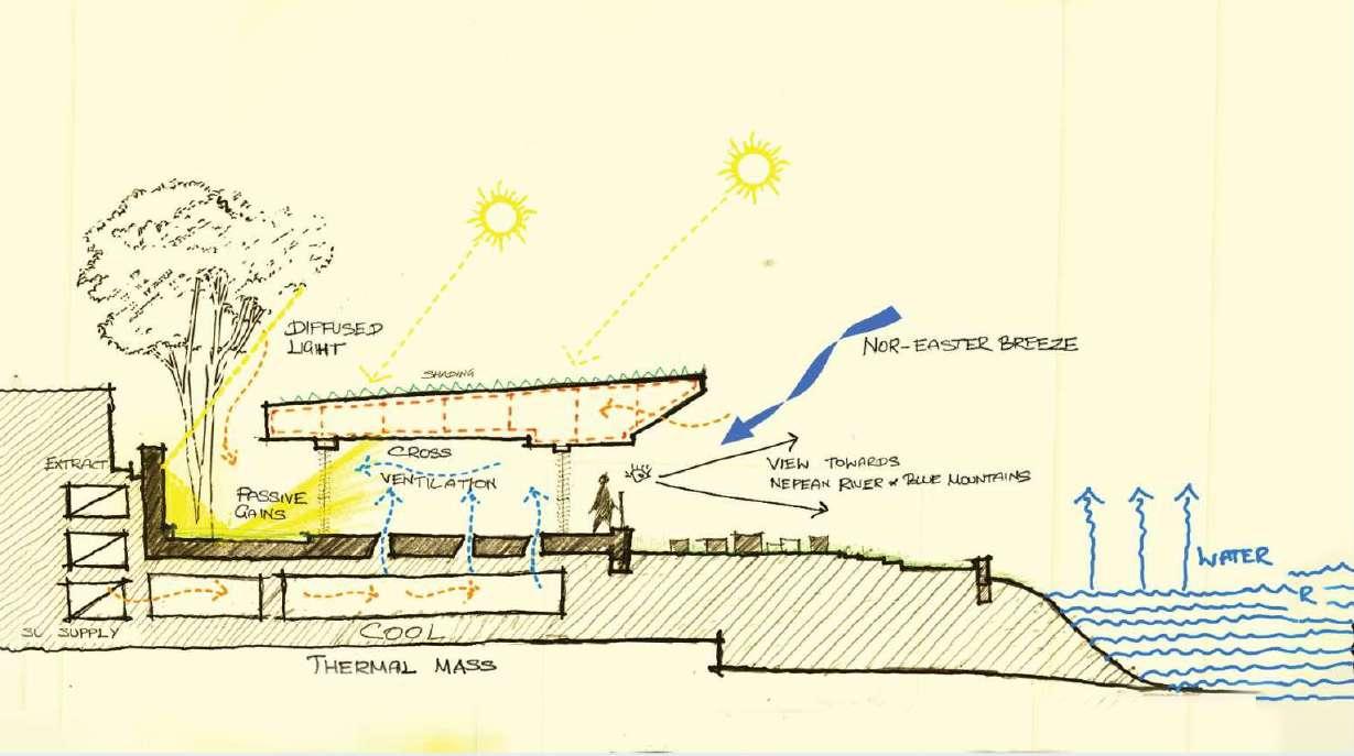
The project brief aimed to design a center dedicated to raising awareness and providing education to the public regarding the urgent need to address global climate issues and cope with extreme weather conditions.
With the average temperature of Australia having increased by 1.47 ± 0.24 °C in the last century, it is imperative that the built form demonstrates resilience to these harsh weather extremes.
16
17
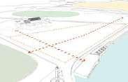
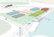
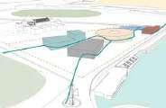
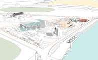
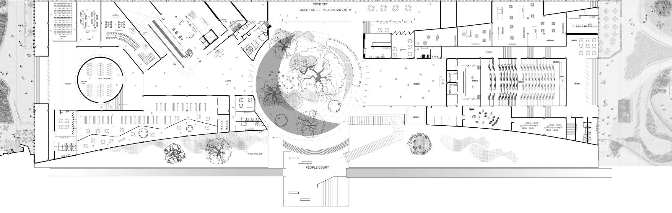
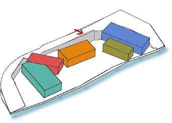
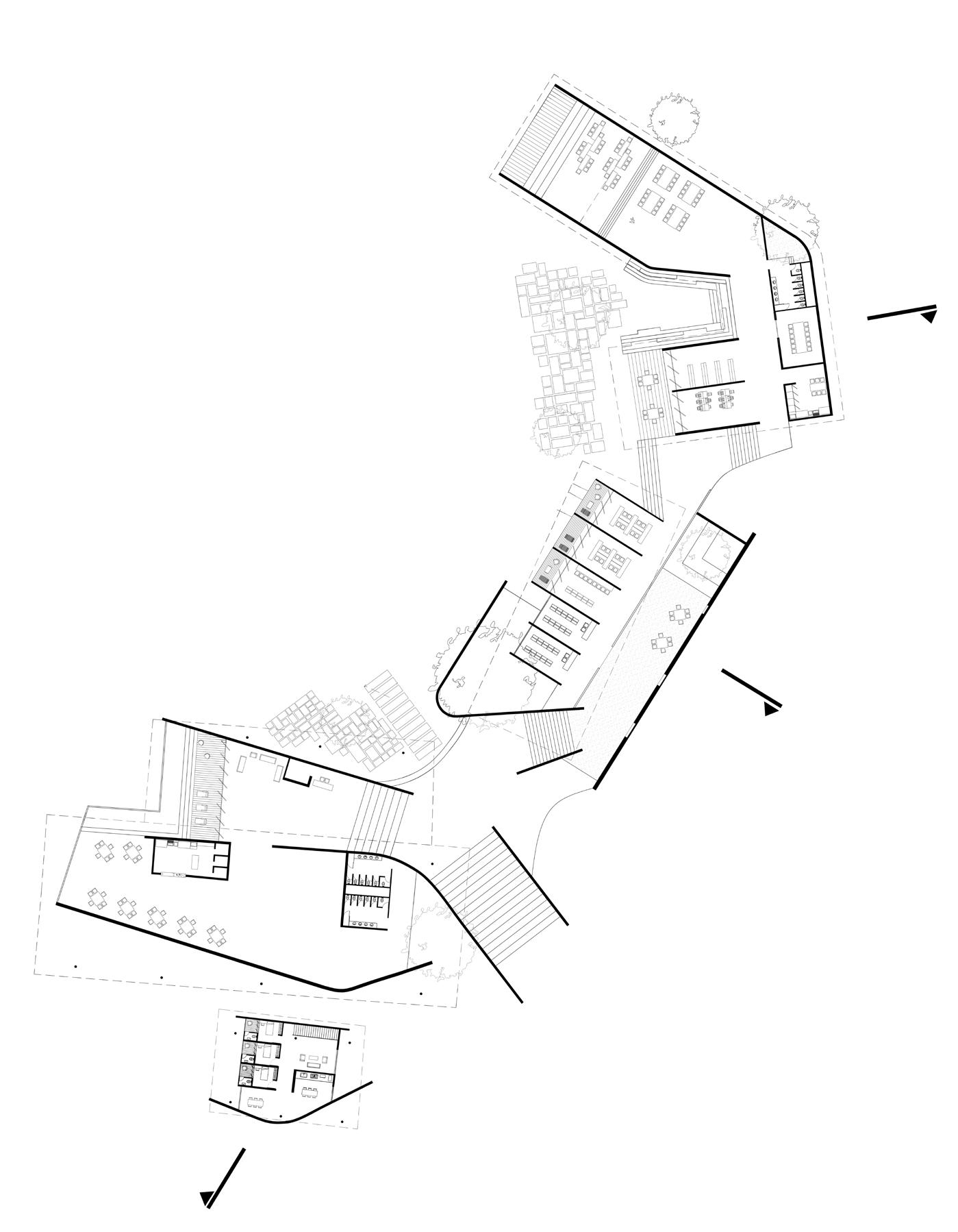
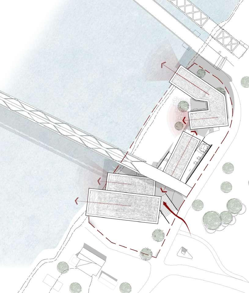
Right I layouts
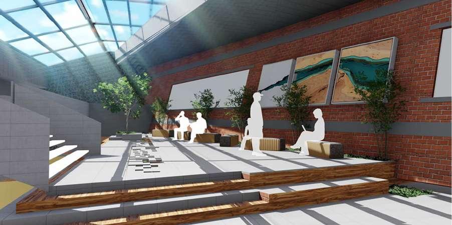
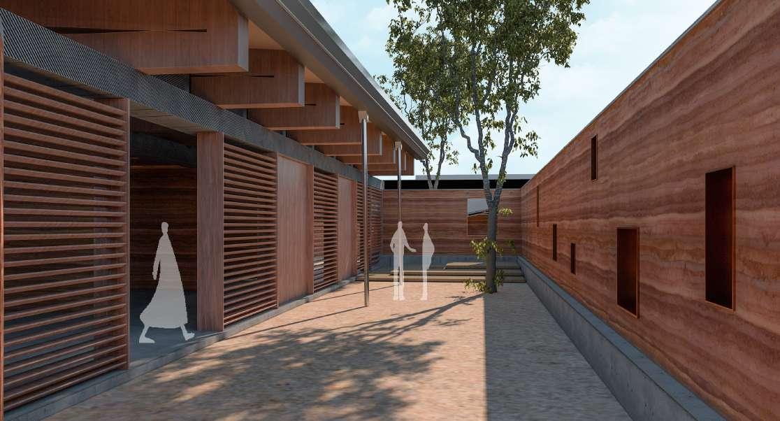
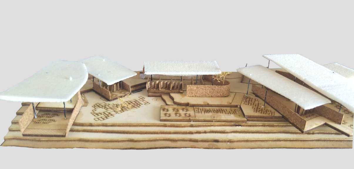
Bottom Right I Internal courtyard acts as break out space
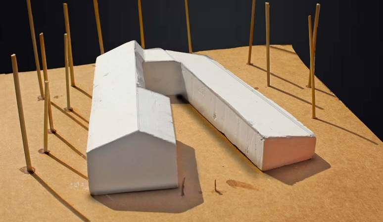
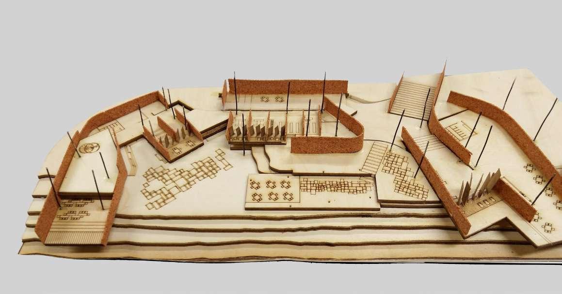
Bottom LeftI laser cut base and hand-made physical model
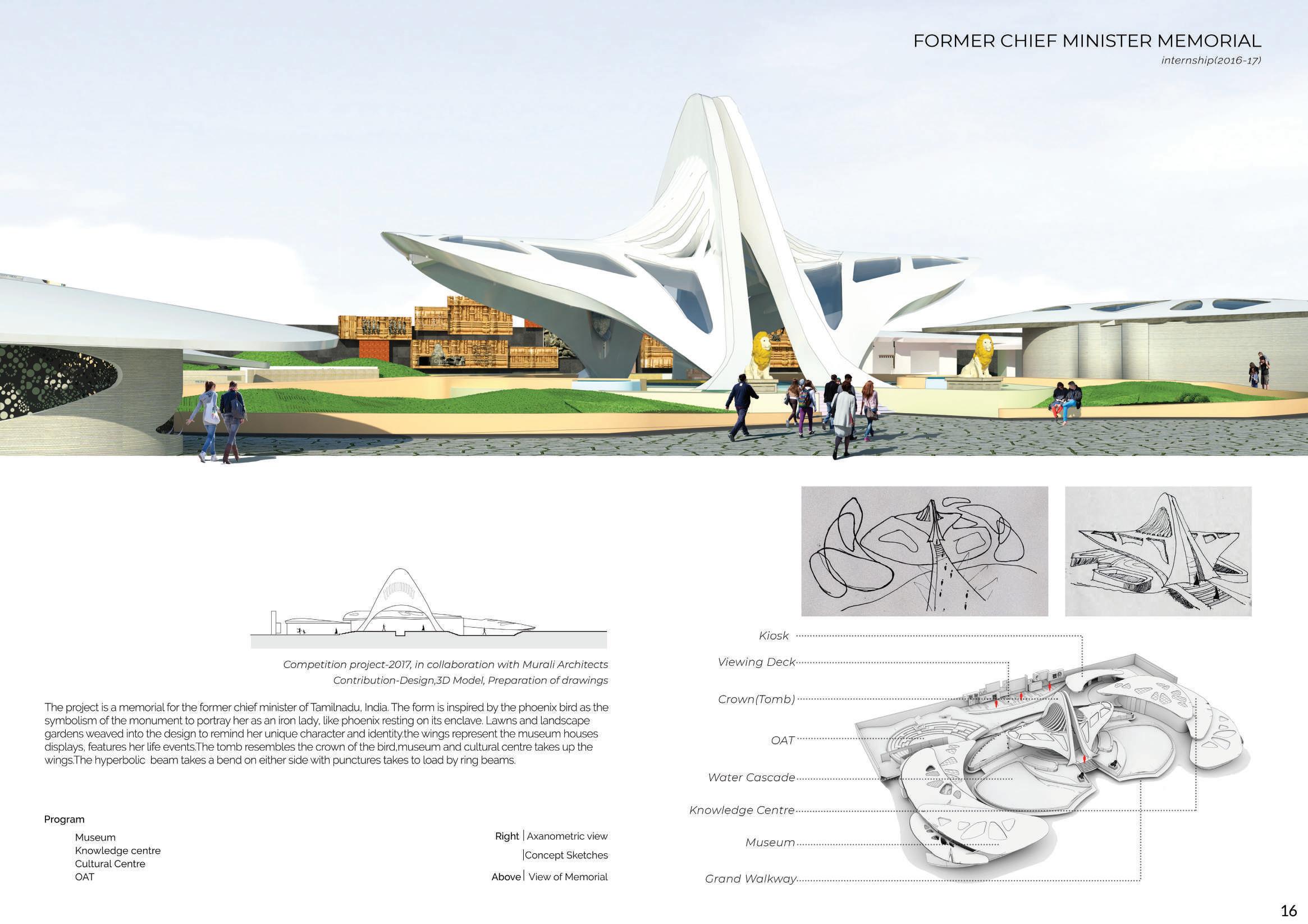
The vast emptiness of the hard landscape, combined with the expansive views of the Blue Mountains and the Nepean River, evoke a powerful sense of appeal, emotion, and timelessness.
18
MGP 12 purlins @1150 C/C
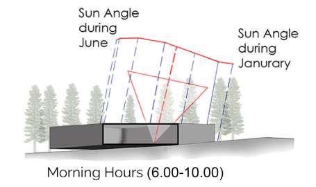
The structure was conceived as load-bearing rammed earth walls with timber roof openings designed to harness North-Easterly breeze winds and diffuse light. Beneath the concrete floor, a labyrinth system runs air through the perimeter of gabion walls, facilitating passive heating and cooling of the air.
19
Lintel concrete 200 mm
Recessed in-slab light
Double glazed sealed
Rammed earth wall 450 mm
Sloping continous water
slope
Timber posts
Steel outrigger
Detailed wall and roof section
Reveal
Concrete beam
FASCIA- copper finish
EAVE- Timber finish
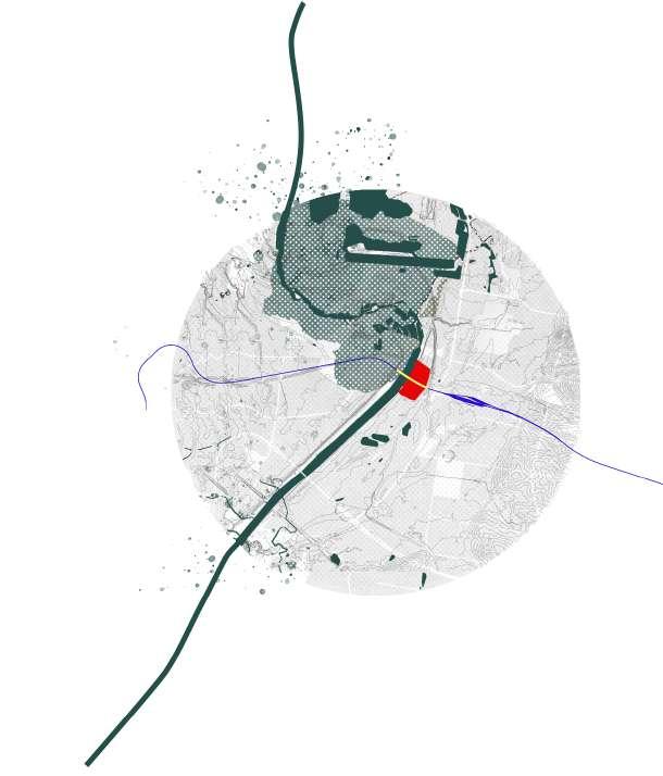
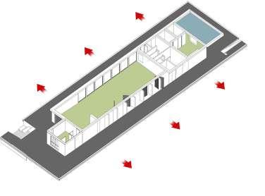
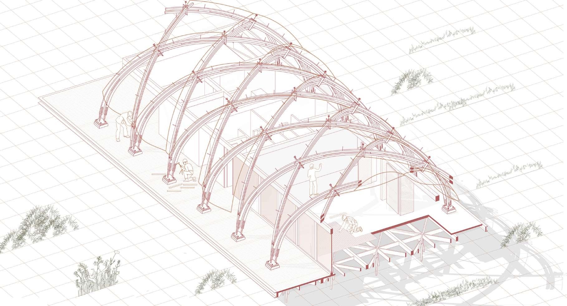
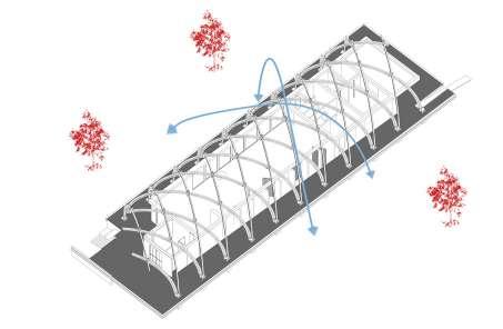
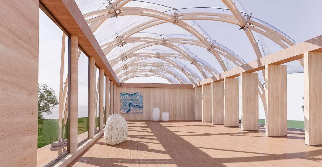
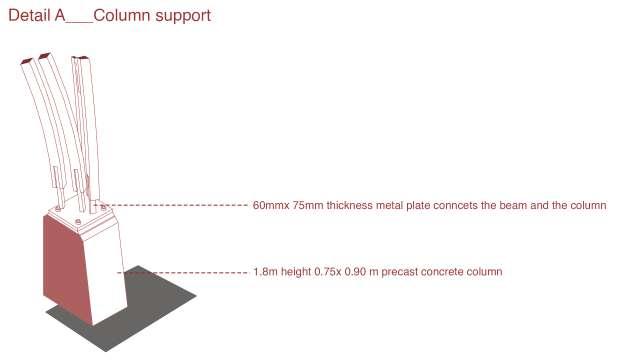
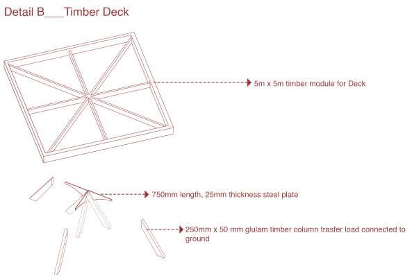
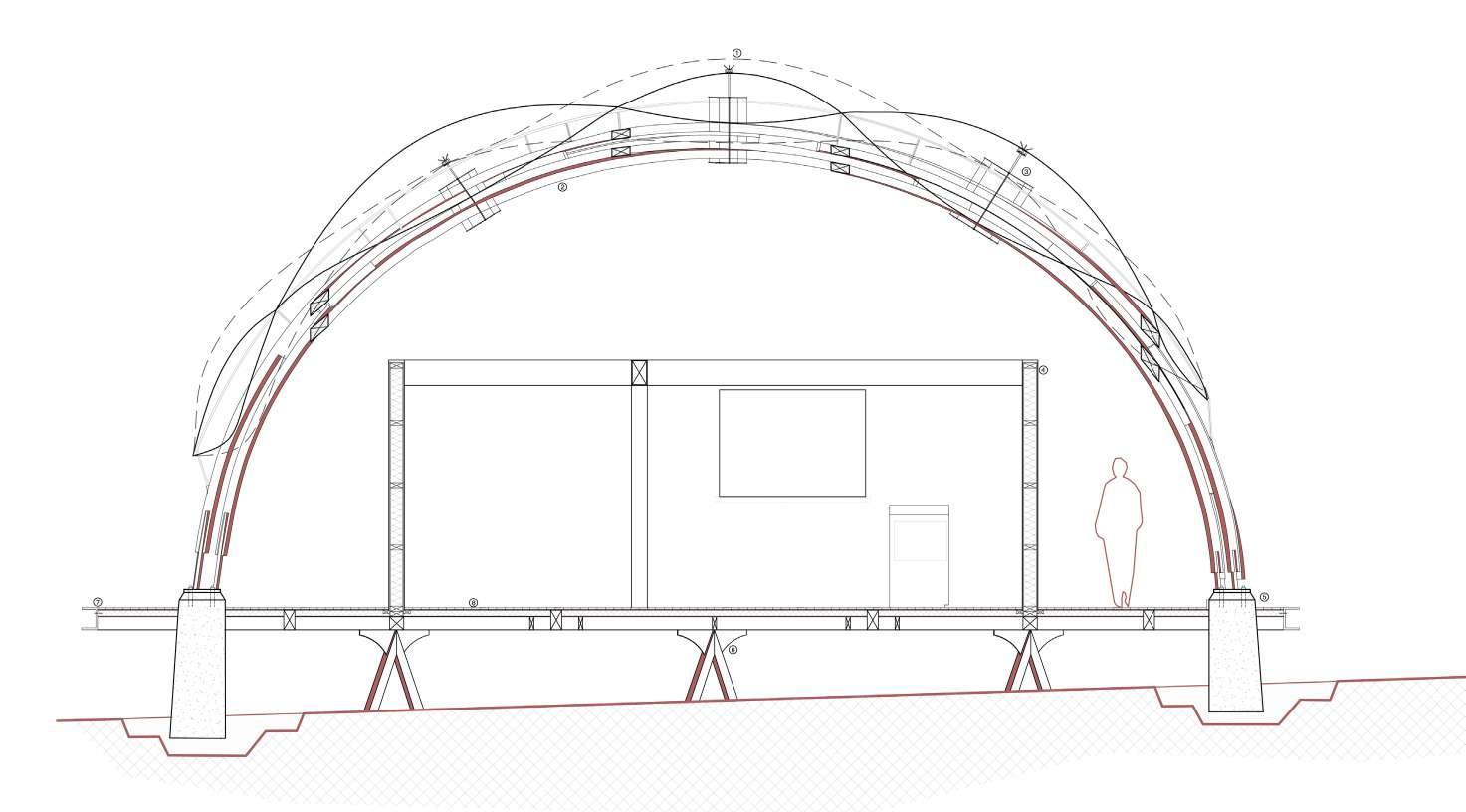
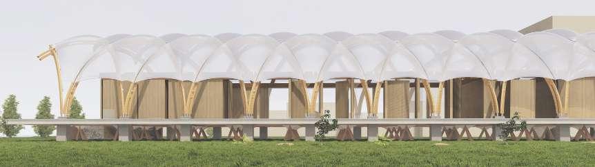
04 SHARK POINT CLOVELLY PAVILION
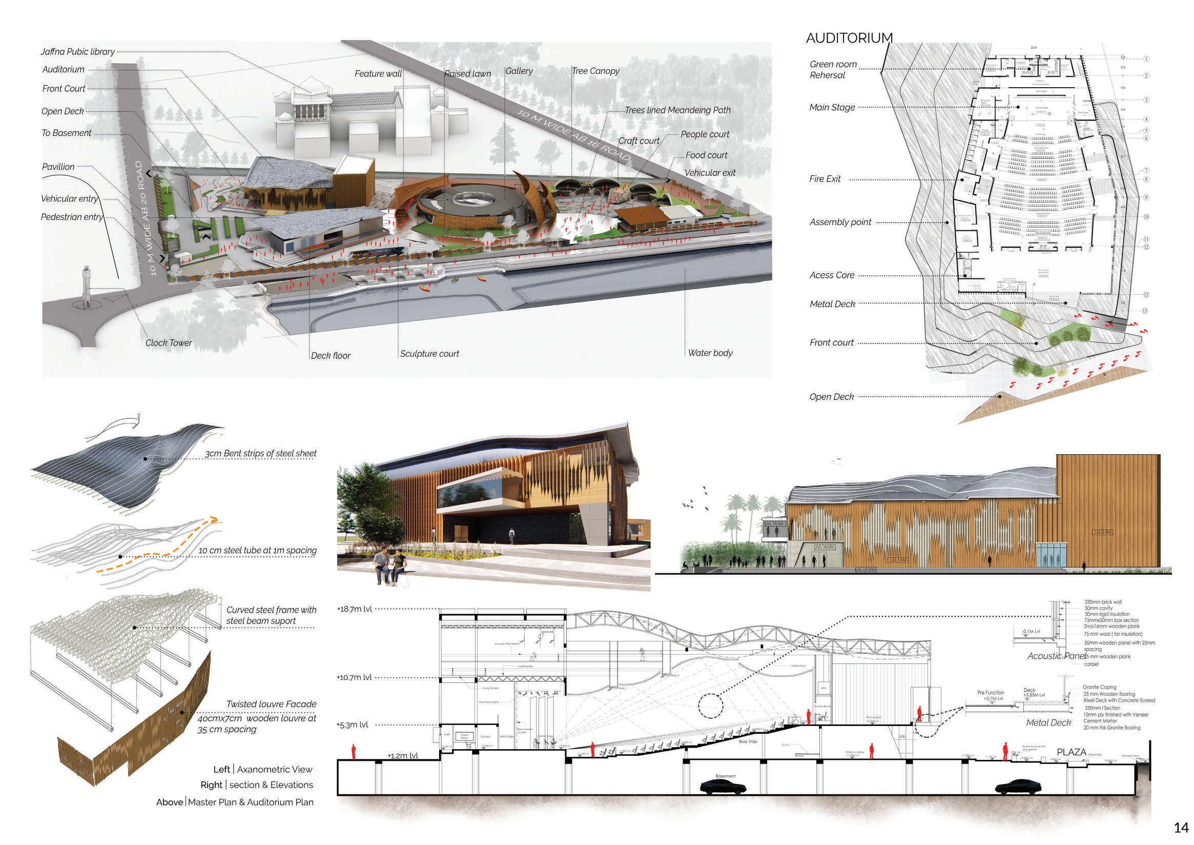
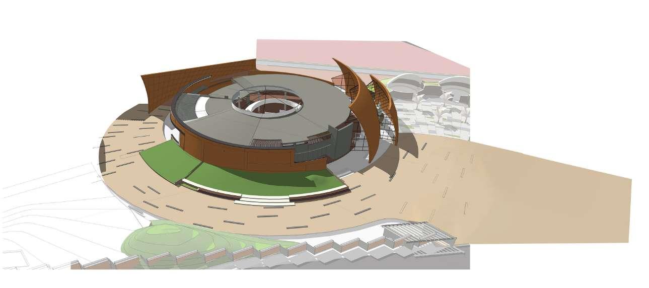
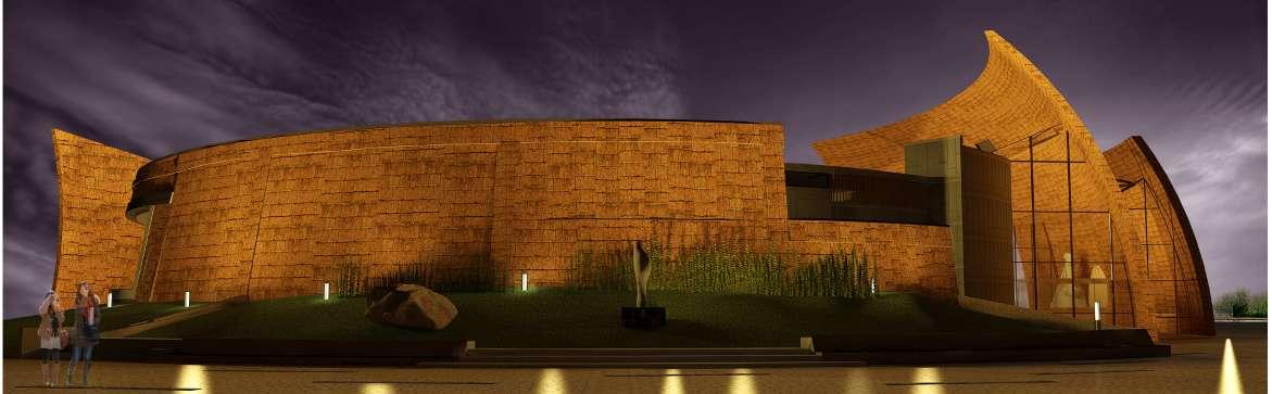
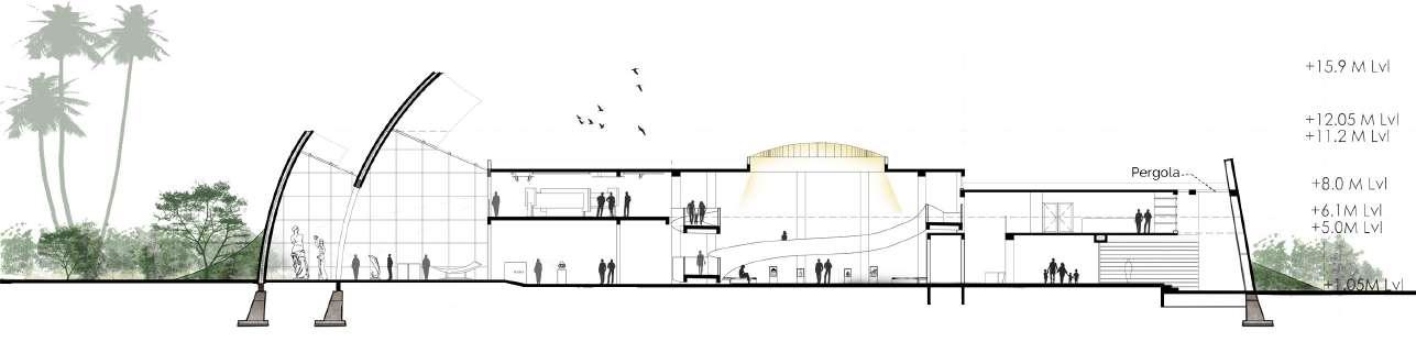
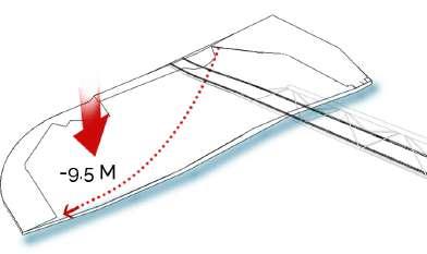
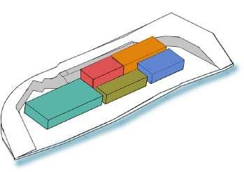
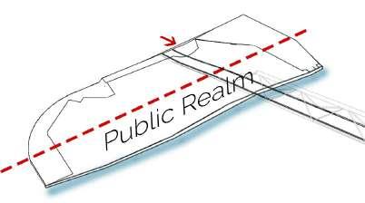
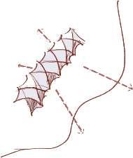
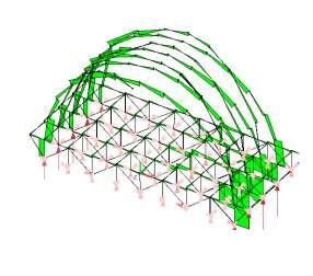
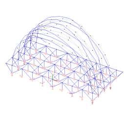
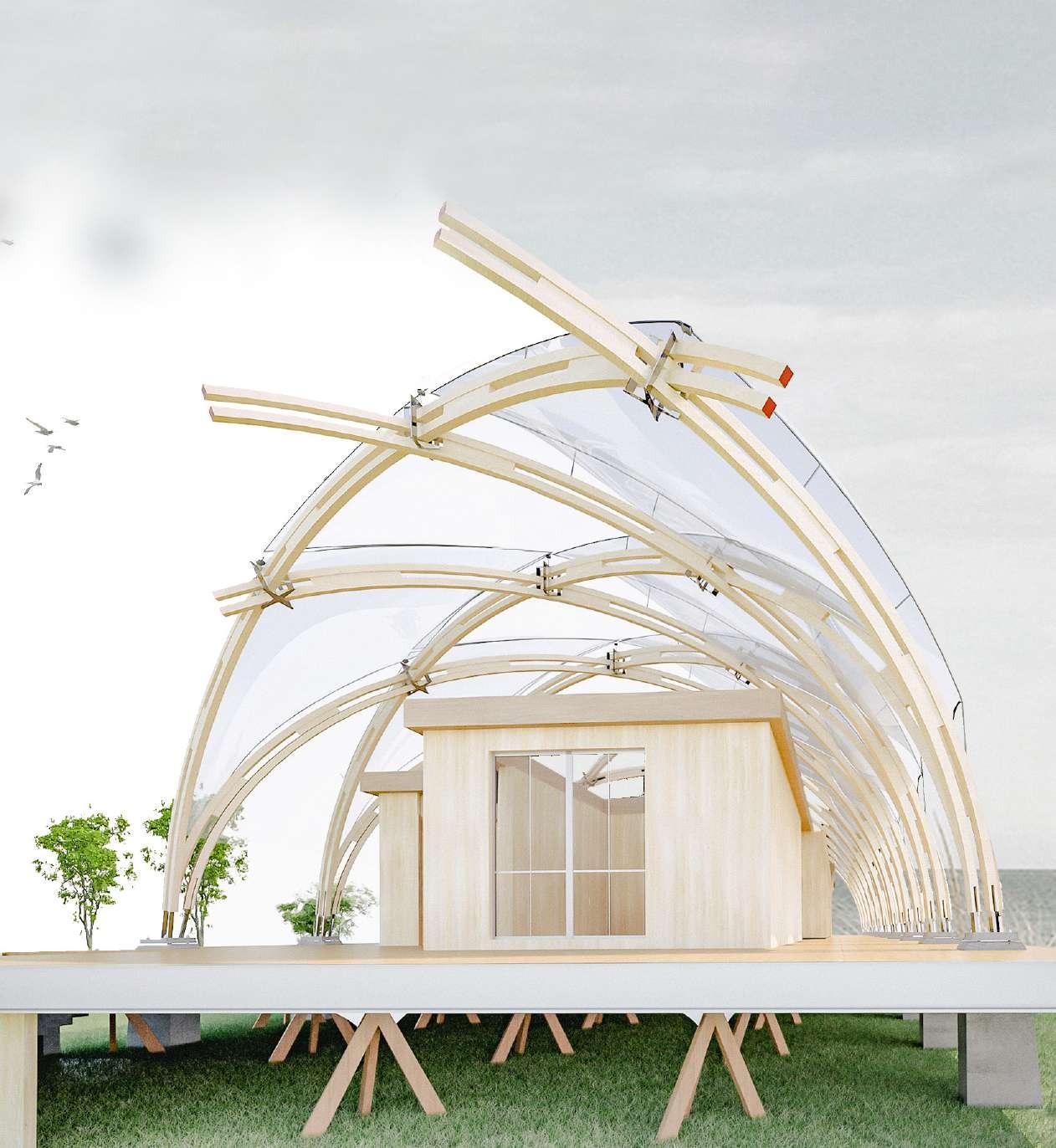
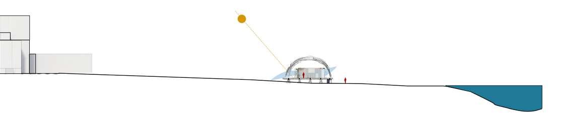
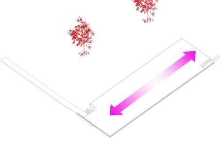
The Beach Pavilion at Clovelly designed to house Gallery, bar, amenities and services for leisure and recreation in the neighborhood. Its oriented in a north-south direction and features a simple yet elegant arch form made up of double-layered laminated Glulam timber laths that span over 18 meters.
The lattice shell of the arches is constructed using 106 x 106mm layers of timber. Additional blocks added to provide shear to the structure. These arches are connected to the post base of Prefabricated reinforced concrete, with the abutment and foundation taking the direct horizontal thrust of the structure.
13
14
15
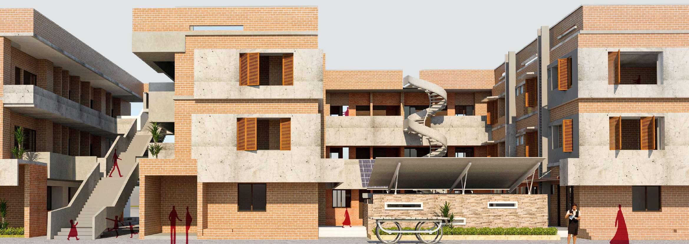
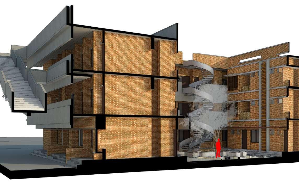
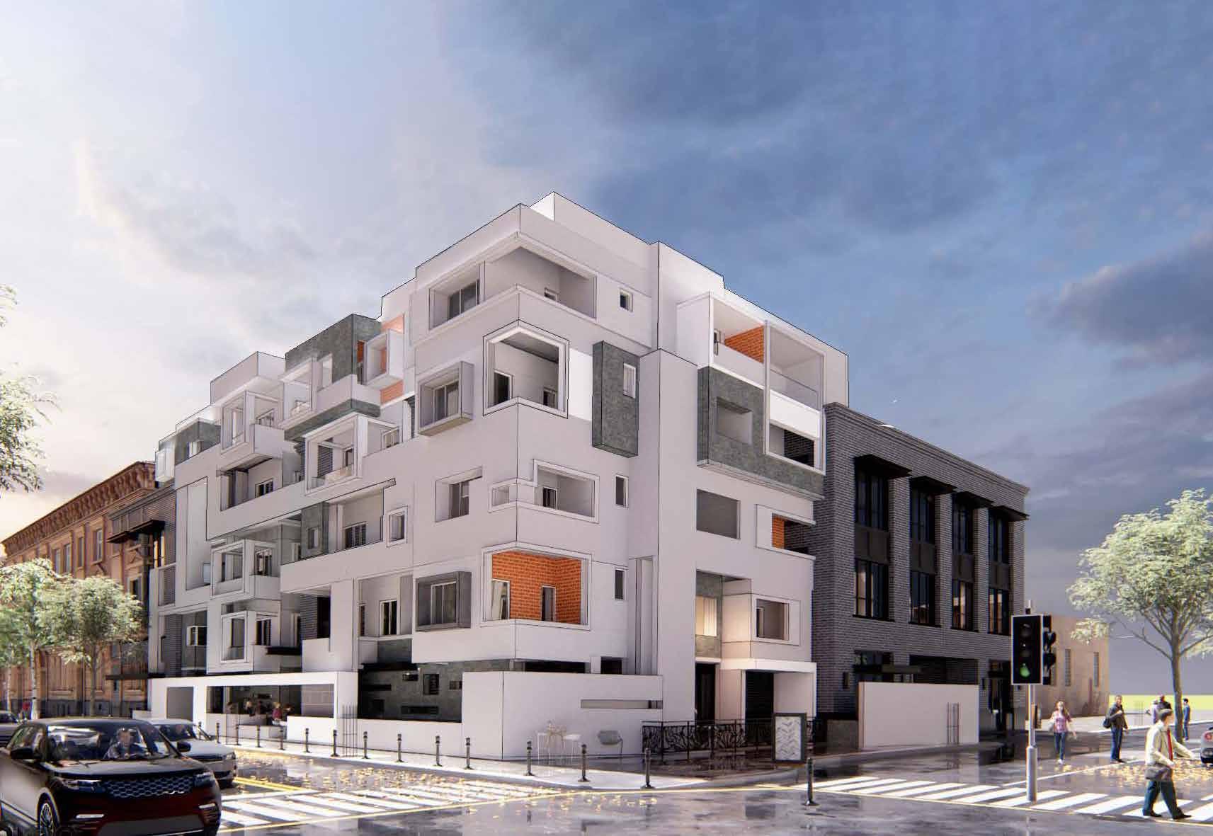
06 SOCIAL HOUSING
Can social housing effectively provide essential infrastructure and bolster economic activity to meet the diverse needs of a community within a single location?
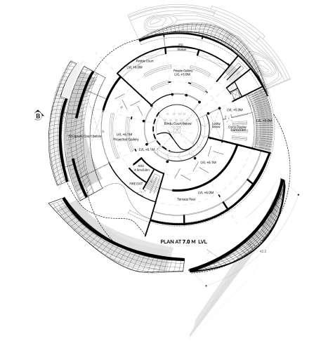
This project seeks to design a social housing scheme that acknowledges and connects with the socio-cultural realities of the Indian community, known for its fluid and dynamic daily activities.
20
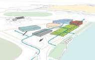
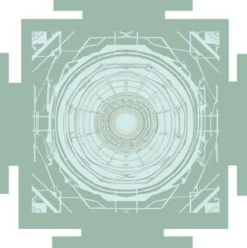
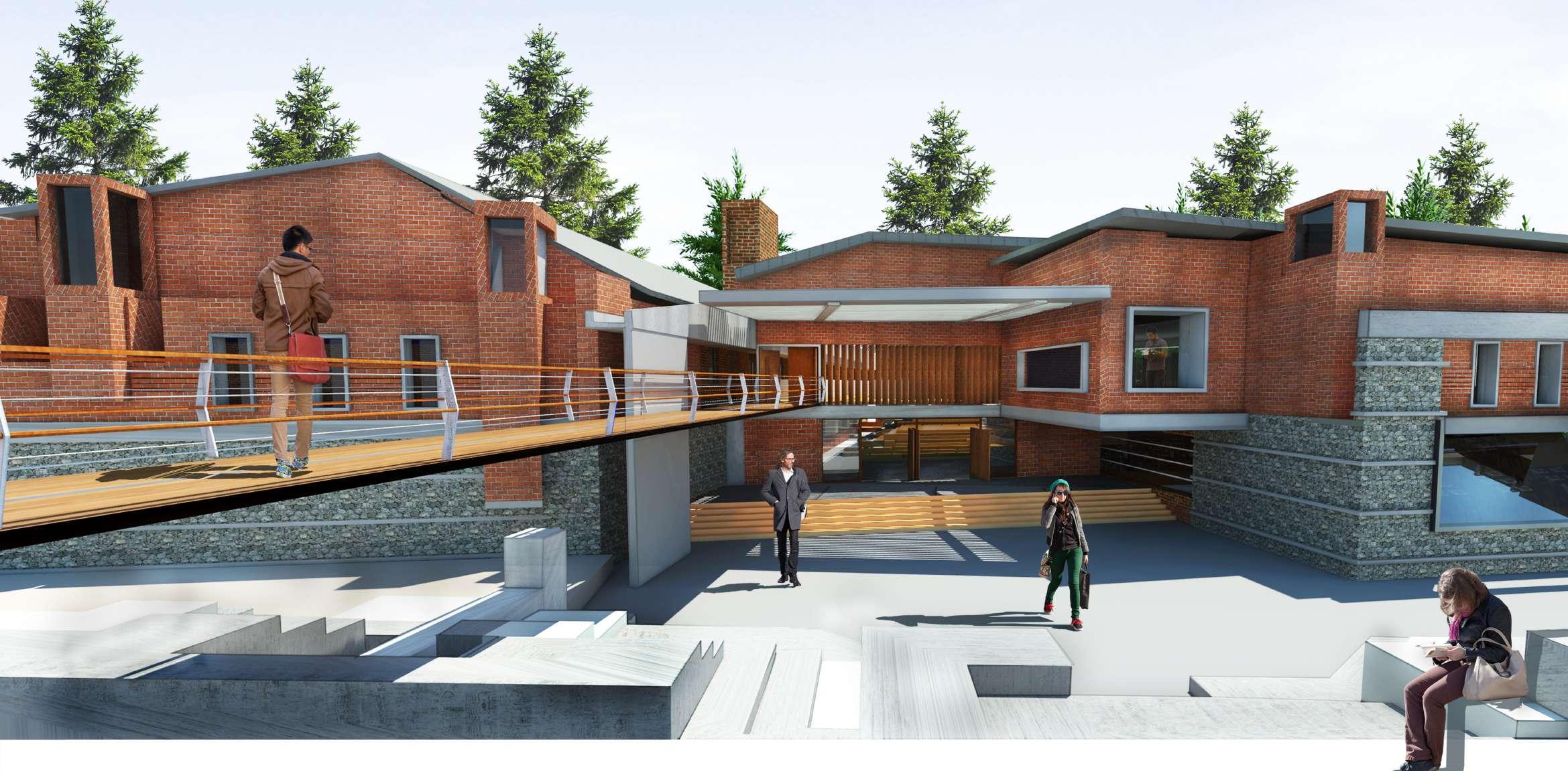
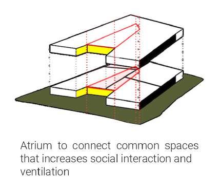
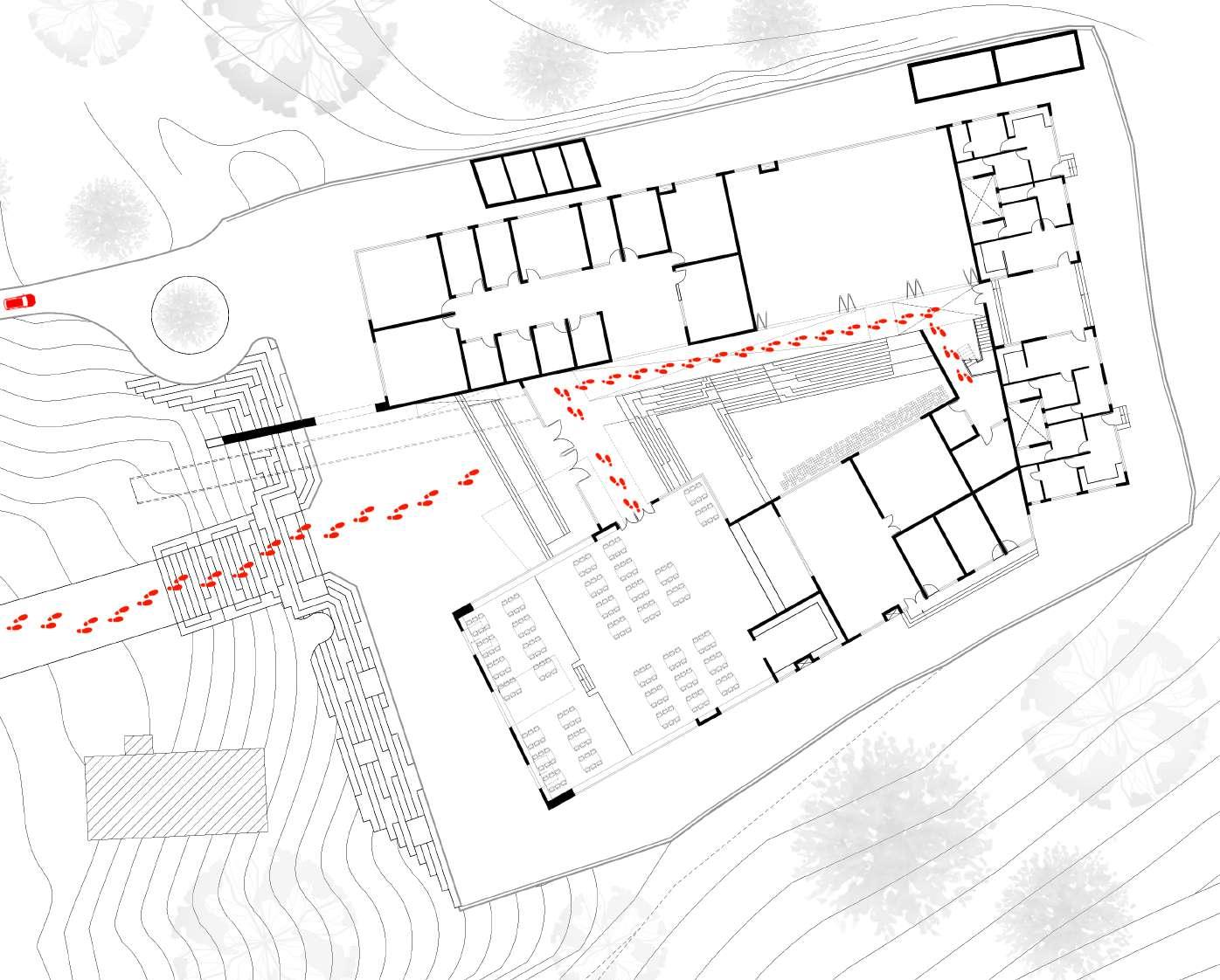
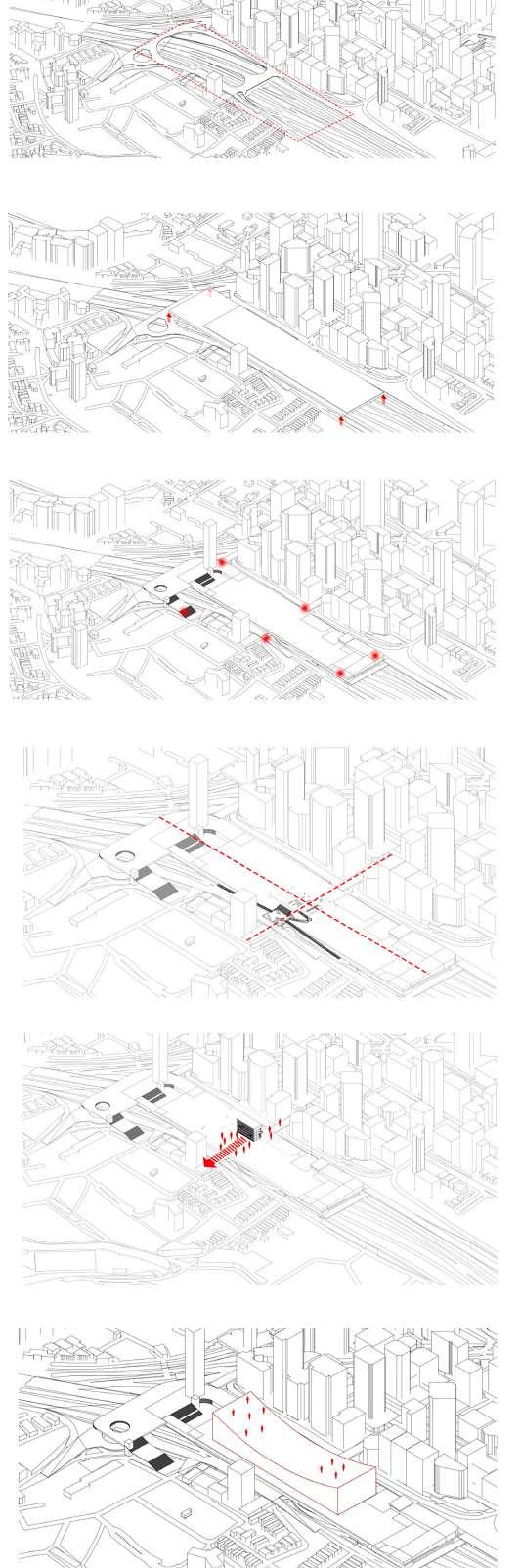
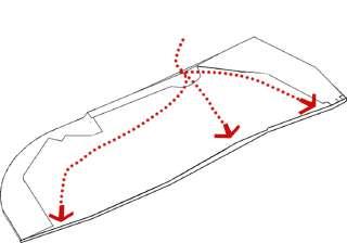
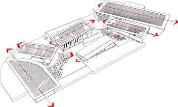
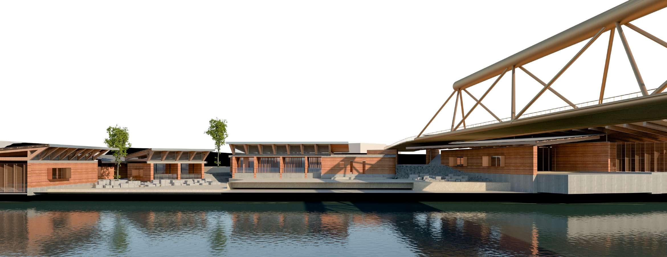
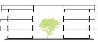
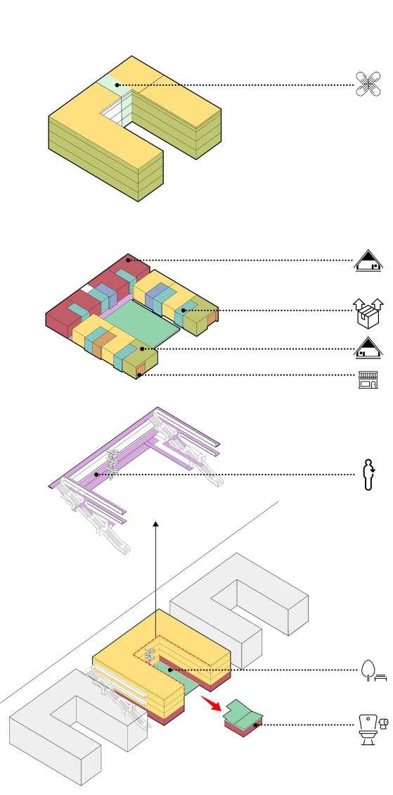
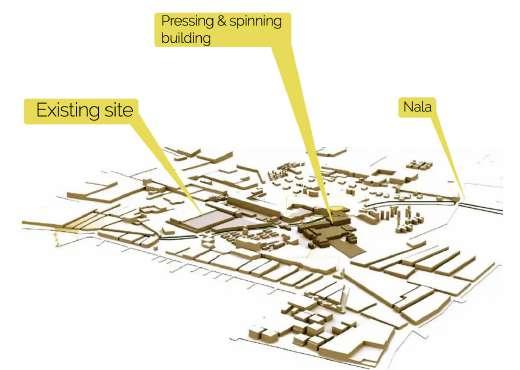
Top Exterior view Bottom Left I Site Plan with extending green spine Bottom Right I Process diagram- building arrangement with courtyard “concept of sharing spaces”
The scheme comprises five blocks interconnected by a central spine and a stringer beam staircase, forming a seamless urban integration that enhances the site’s connectivity and accessibility.
Each block features ground-floor shops, promoting economic activity and fostering community interaction at street level. This design not only creates defensible spaces but also enhances sociability within the community.
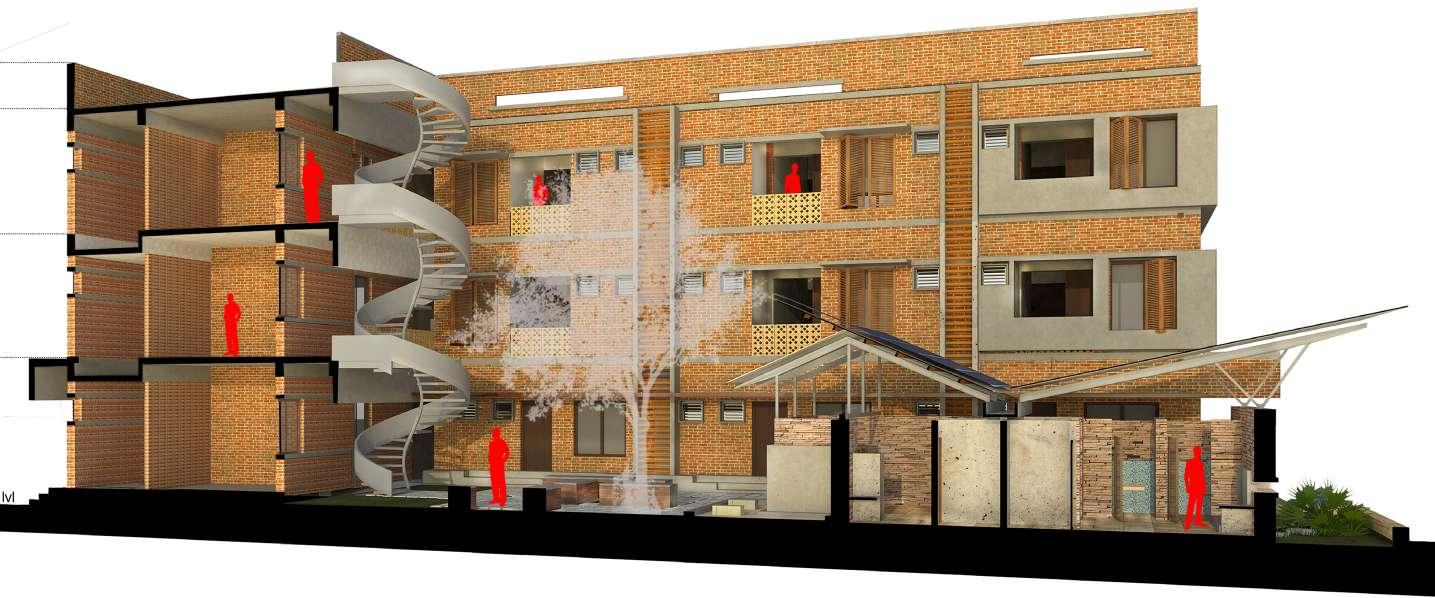
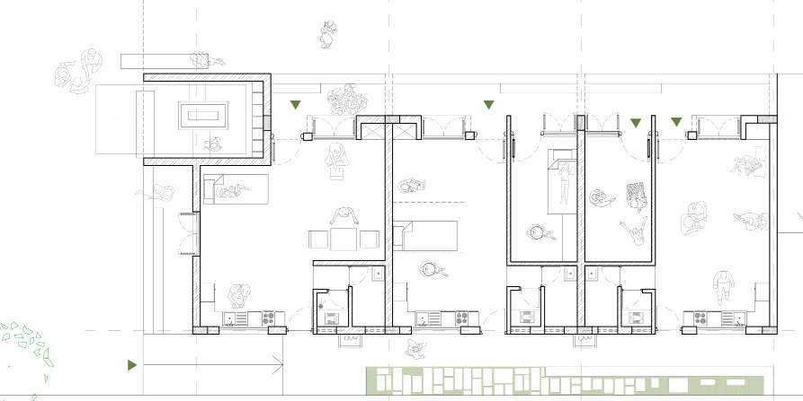
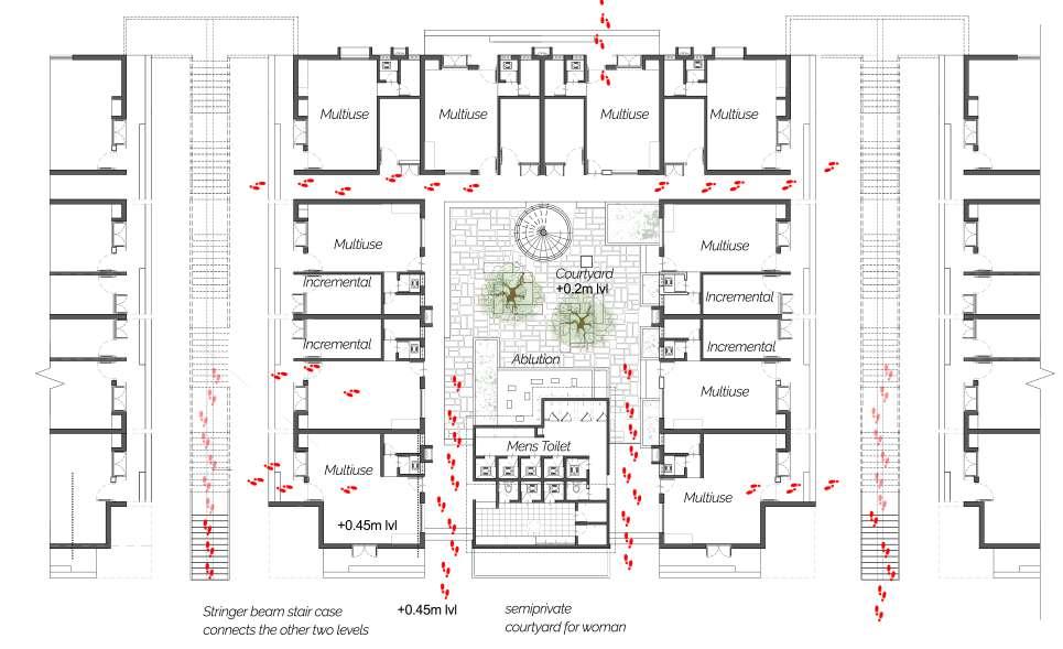
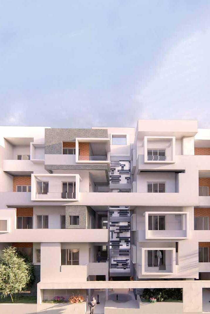
The upper floors feature units arranged around functional courtyards, serving as backyards for residents and offering them opportunities for healthy recreation and access to essential amenities.
These units are designed to be flexible and adaptable, capable of accommodating multi-generational living arrangements and accommodating the fluid activities of residents. Additionally, they provide incremental space that can be rented out or customized to meet future growing needs.
21
Community Room Dwelling Unit Type 1 Incremental Dwelling Unit Type 2 Retail/ Eateries Main Circulation Courtyard Acessory/ Utilities
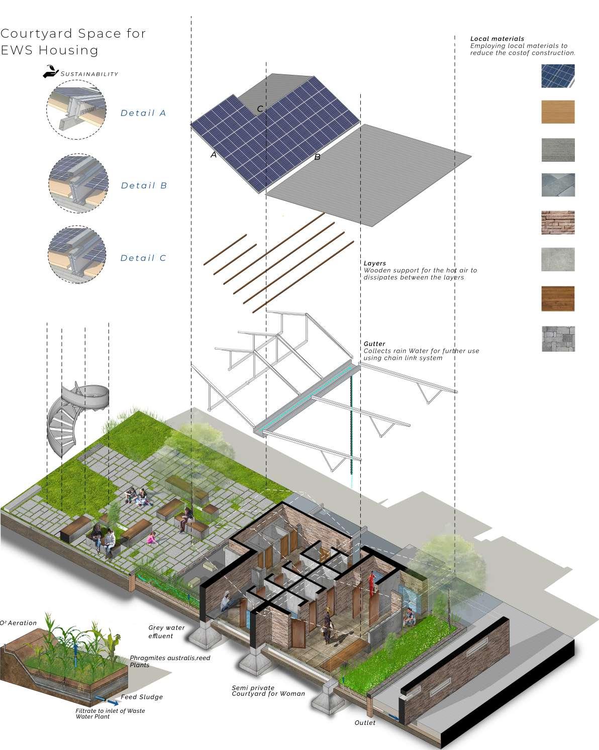
22
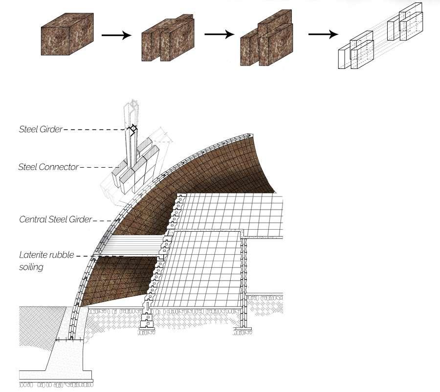
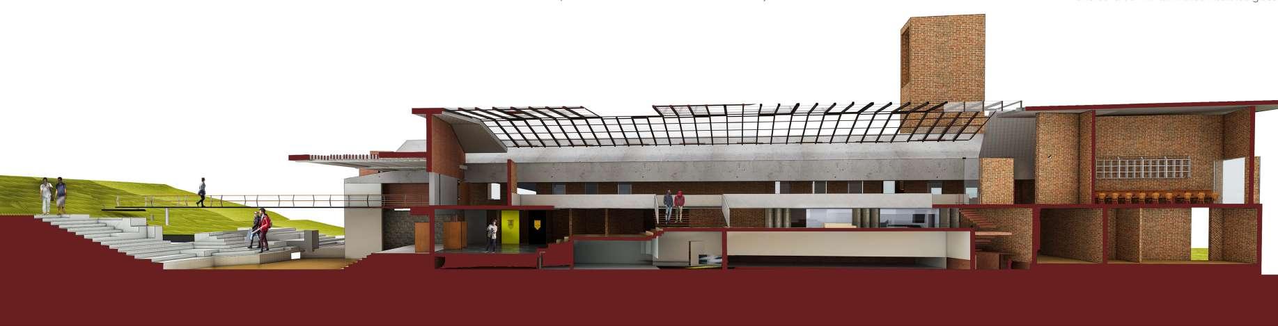
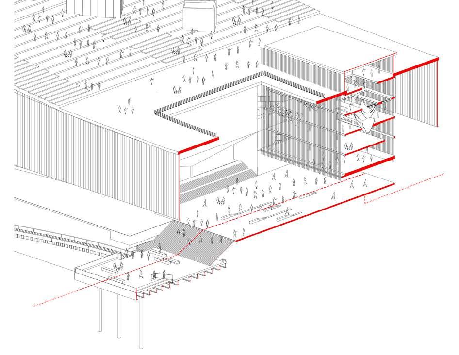
Left I Exploded Axanometric view of Internal courtyard
Right I Section through court
The construction system is a simple exposed brick and concrete system that gives a humane scale and character to the facade.
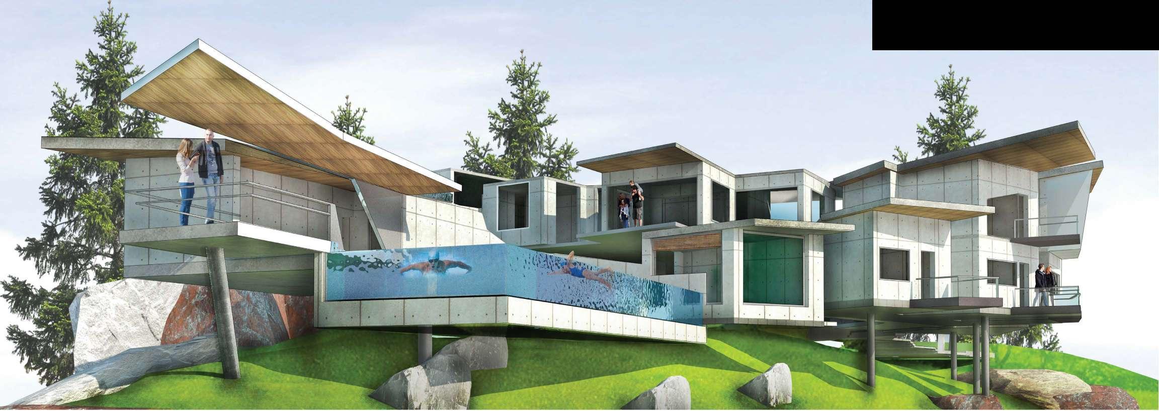
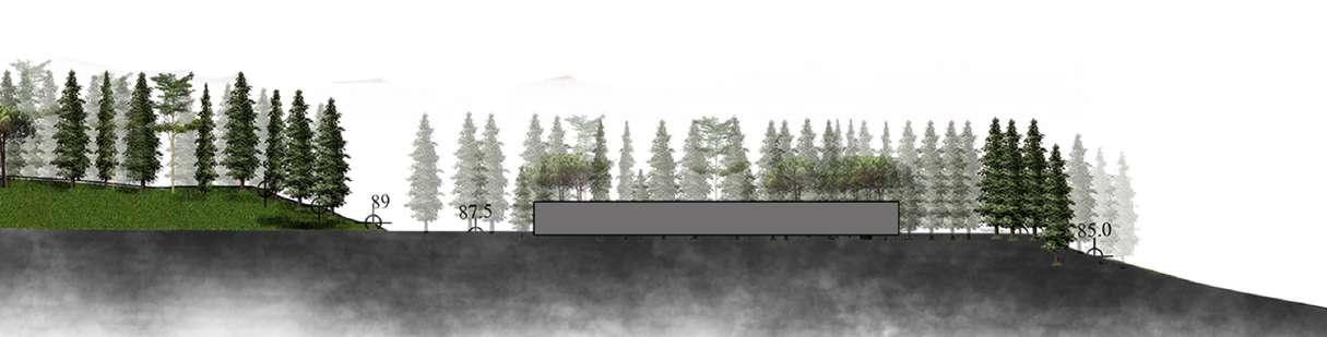
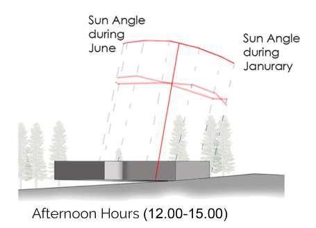
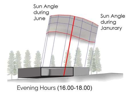
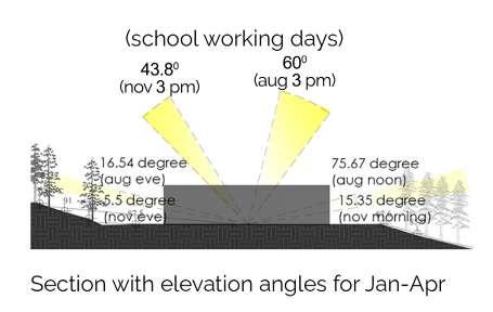
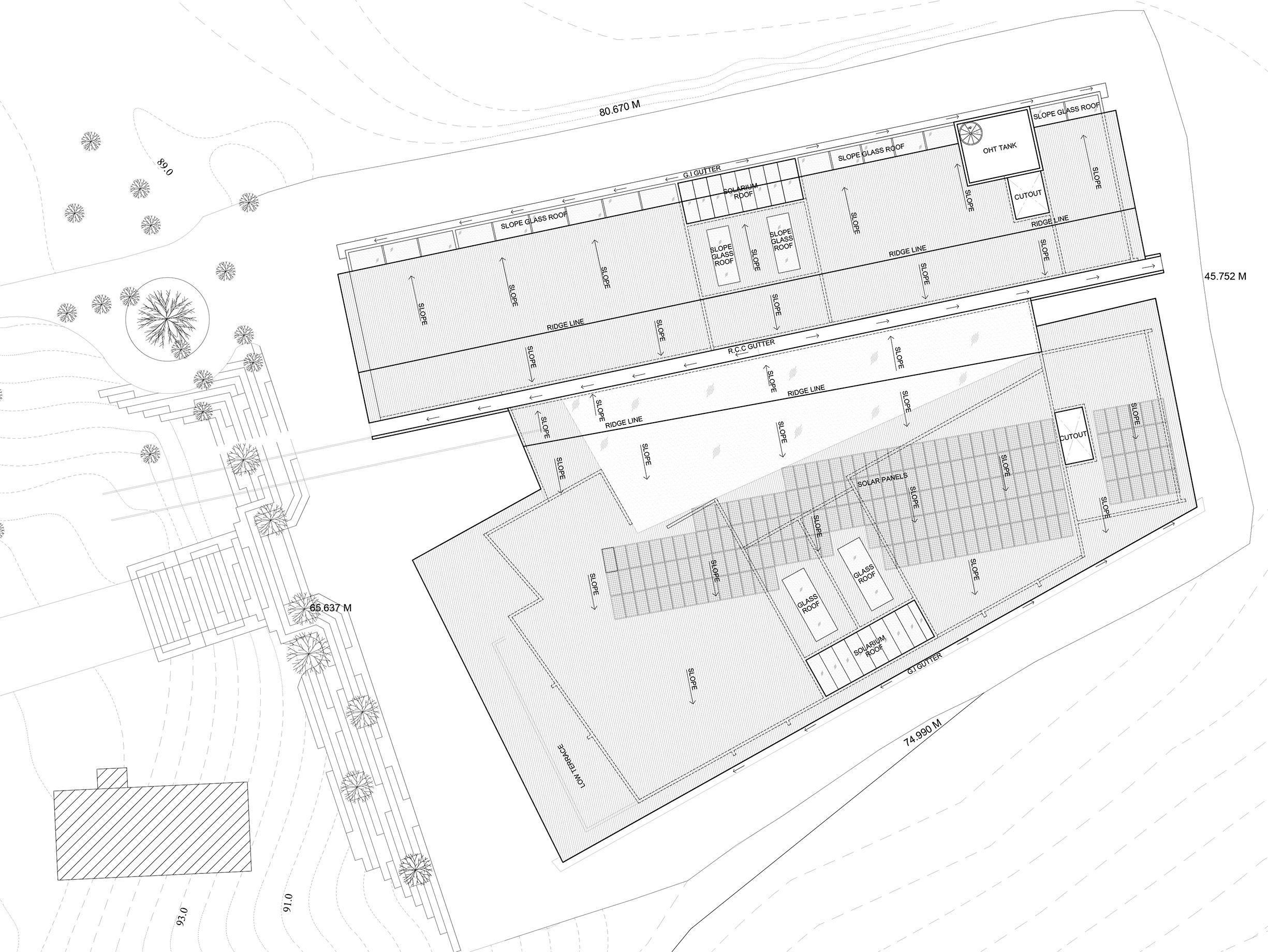
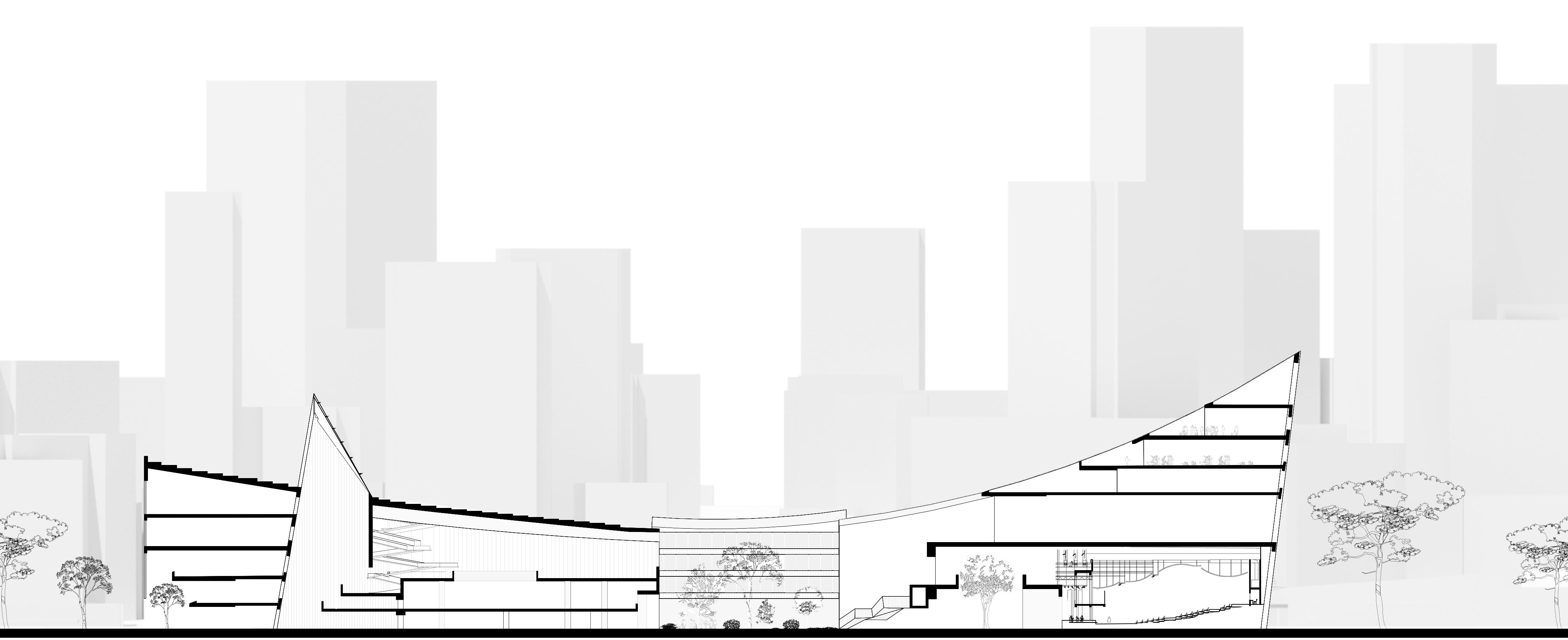
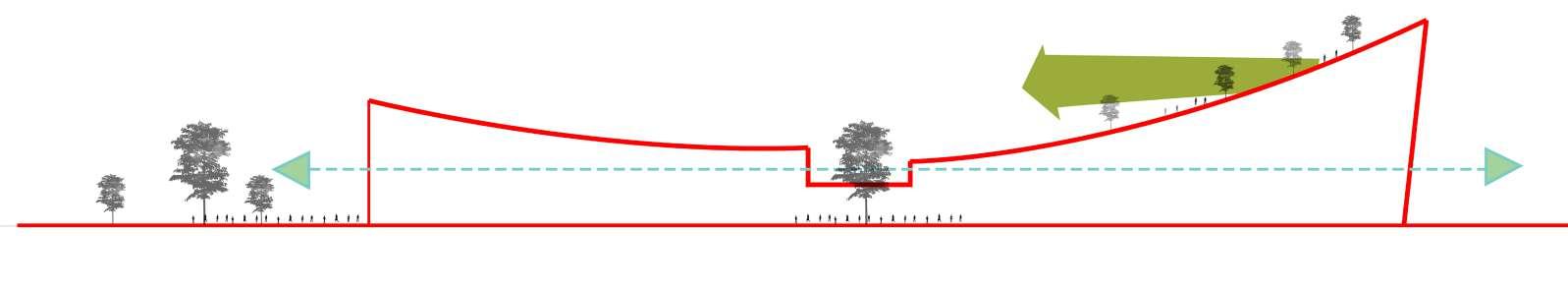
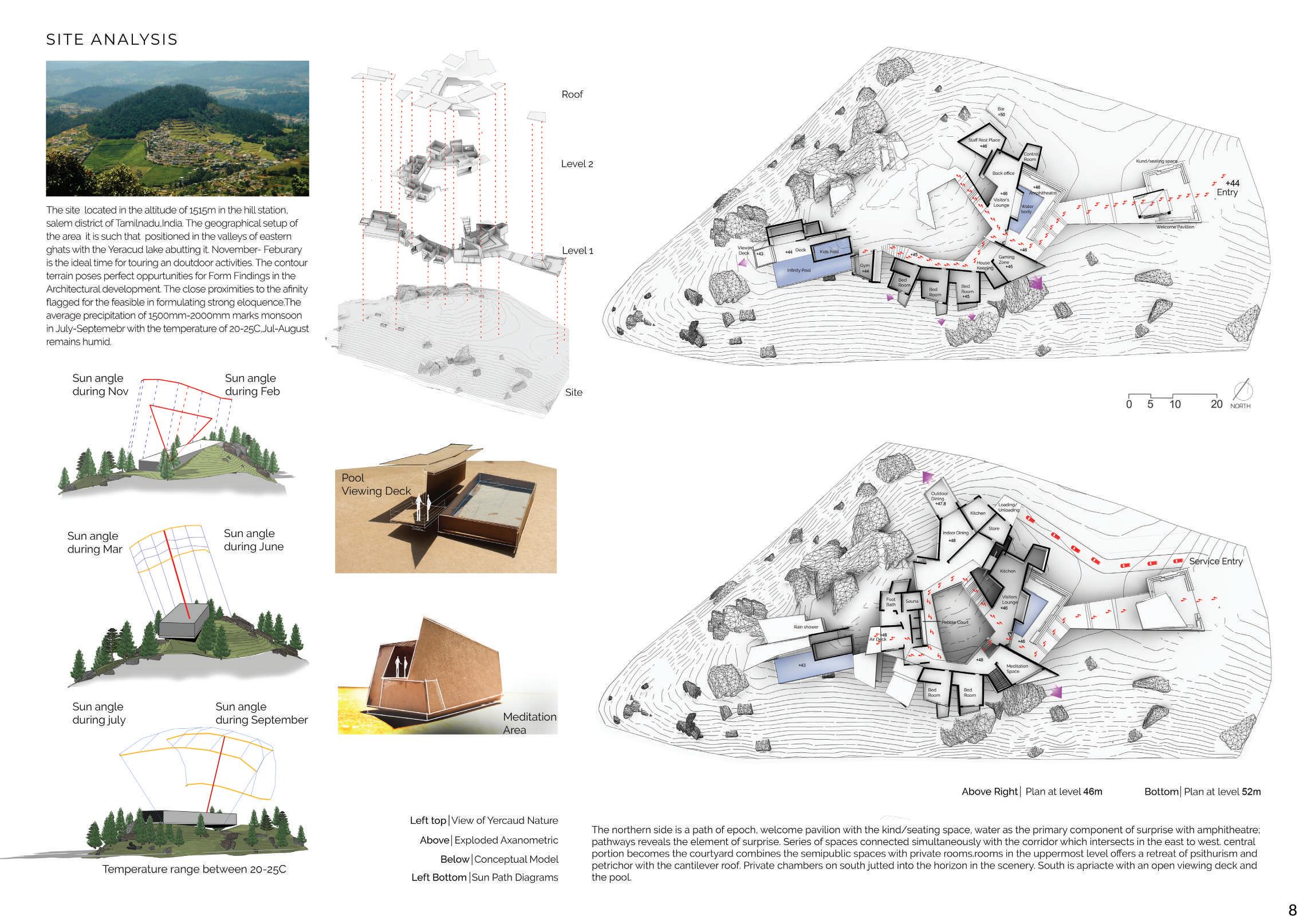
The site unveils itself to the nature's creation in the small cliff with lush pine trees girdling it Existing landscape grants me opportunities in a design brief aided me in the development process. Desideratum to effectuate visual composition sculptured in angular forms in the elegant setting by balancing the nature as a backdrop in the scenery, which hugging and seeping its environment retained the existing trees and rock with minimal clearance to enhance the surrounding setting. Voluminous of each room gel with the nature projecting out in cantilevers to experience the drama in nature. Arrangement of distinctive spaces create anticipation as the user encounters the spaces.
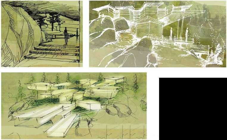
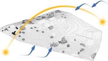
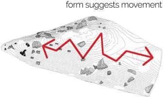
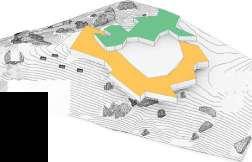
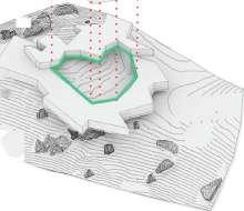
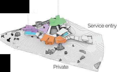
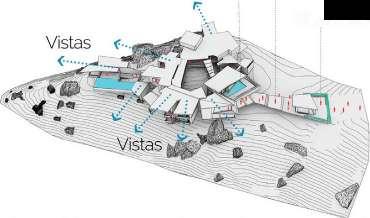
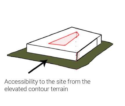
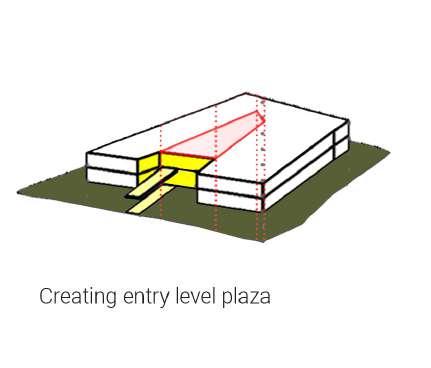
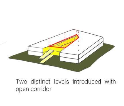
Right Process Diagram Left Concept Sketches Above Rear View of clubhouse The site is contour terrain in Yercaud with an area of 2.1 Acre at 44m altitude.Blue indicates the direction of major wind flow Cut ,r- \;'IA! � �--""--.;.,�4�� Cc 't ��,-� $... �Q�,� Centre portion is removed to from the Court.corridor runs around the court.binds the rest of the program THEABODE,YERCAUD arranged the spaces in N-S, To Maximize the views and to bring in more light and warmth indoors, Semi Public Semi pr vate r(_ -� programed the functions strategically in a way to maximize the vistasPrivate rooms arejutted out in west to the forest coverViewing deck on the south. Club House Two levels 7 ··IA[ , - i .���-� -��� For user to appreciate the beauty of nature,i made programs in the two levels with the interconnectedness of spaces. Path of epoch Water Body Kund/seating Cantilevered Concrete roof Frame these spaces and rooms are aligned to experince the vistas arround,Water as an traditional element used 7
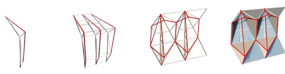
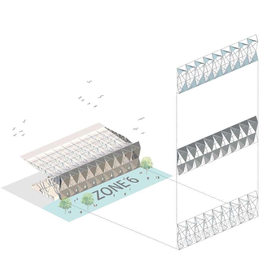
07 DOCUMENTATION TECHNIQUES
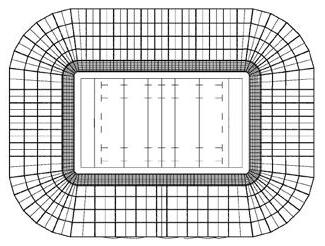
The course focuses on documenting the design of the Western Sydney Stadium, providing students with a schematic design to prepare a complete set of construction documents and drawings. This involves detailing wall information and creating schedules that adhere to the necessary Australian standards using Revit.
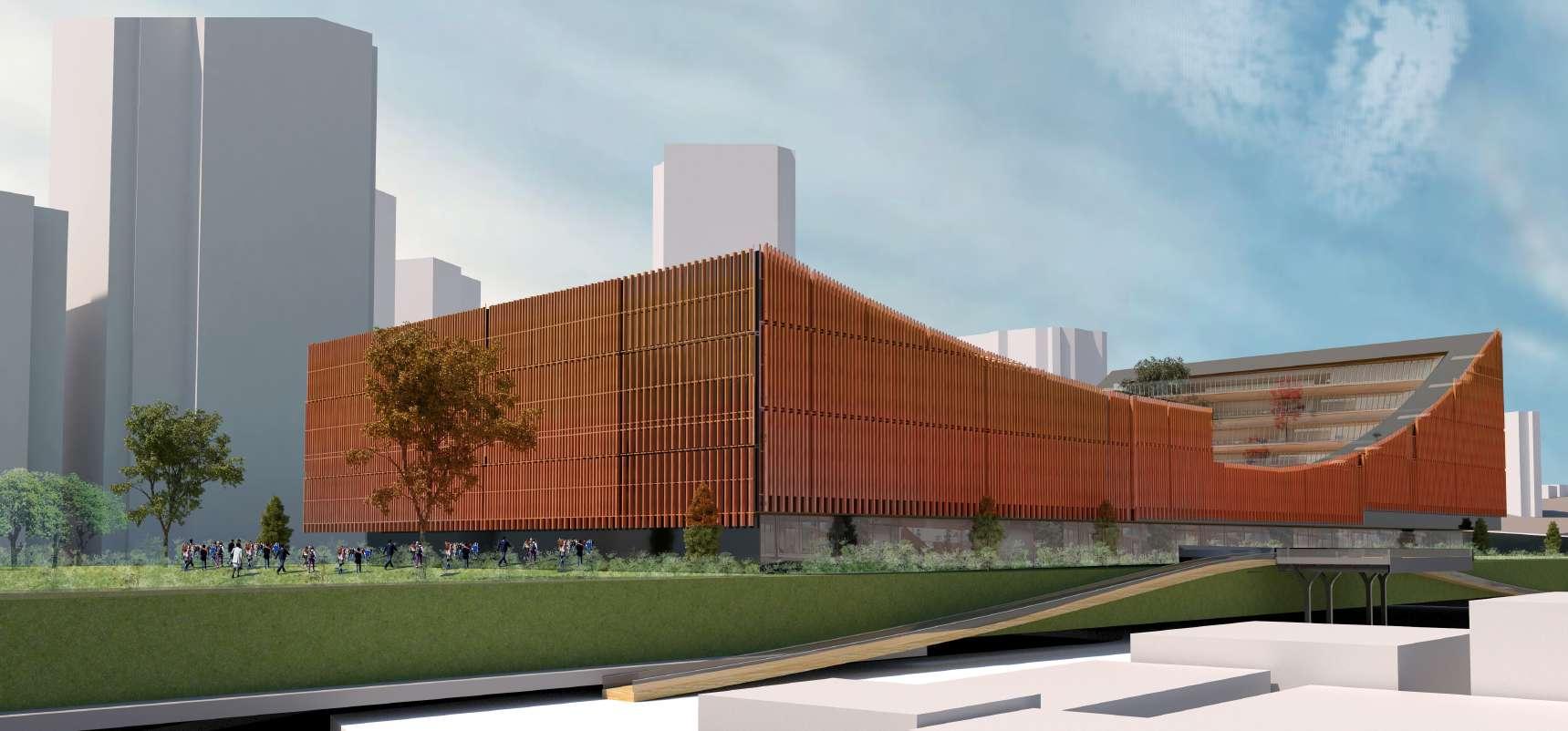
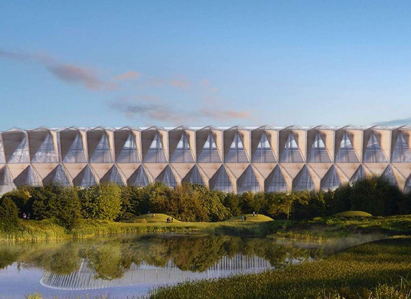
A group of three students proposed an alternative facade design for the eastern side, aiming to establish a connection between the past and present by drawing inspiration from the surrounding contextual heritage, particularly the Old Government House building constructed of sandstone.
The structure itself draws inspiration from an icosahedron, with materials strategically oriented. Polycarbonate and glass were selected for their transparency, allowing natural light to penetrate the interior. Sandstone was also utilized alternately to mitigate unwanted sun exposure in the concourse area.
23
Right Top I Structural development of Icosahedron and the other elements Bottom I Exterior render
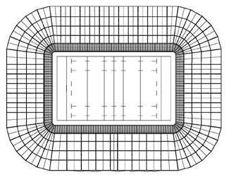

24 41 40 39 38 37 42 43 44 45 46 X1 X1 X2 X2 42 m² 01-K20 F&B 147 m² 01-W21 WC 151 01-W31 WC F 119 m² 01-K25 F&B 20 m² 01-W27 PARENT ROOM m² 01-W22 WC ACC 29 m² 01-B26 BIN ROOM m² 01-B11 CLNR ROOM 01-W20 WC M 82 m² 01-K21 F&B KIT m² 01-U29 COMMS CPD 26 m² 01-B10 STORE KEGS 3273 m² 01-U18 NODE MDB 01-U19 ELEC DB ? 75 m² 01-W45 WC M m² 01-W46 WC ACC m² 01-W42 WC ACC 01-B22 STORE KEGS m² 01-B28 CLNR ROOM 01-B29 CLNR ROOM 10 m² 01-U58 MDF 00. BLK1 00. BLK1 11. P1 02. BLK1 00. BLK1 00. BLK1 01. BLK1 01. ILX09 00. BLK1 11. P1 00. BLK1 00. BLK1 00. 4 BLK1 00. BLK1 11. P1 00. BLK1 00. BLK1 00. BLK1 00. BLK1 00. BLK1 00. BLK1 11. P1 11. P2 11. P1 00. BLK1 00. BLK1 DOOR DOOR DOOR DOOR DOOR DOOR DOOR DOOR DOOR 1020390100025251000 10075 1000 385 6005 3140 920 7500 920 5975 1000 16295 1000 200 290 1000 4520 1000 7865 10002580 6000 26051000 4400 1020190 200 30501753001000 3085 190 1000 190 6610 195 190 3005 30001902200 190 1570 190 2395 105 690 105 33351901410190183019012002080190 9345 9345 190 665495 105 9301360190156519014101903285 105 780 105 2515 190 1410 190 2200190 6000 1902110 180 15101753035320 170 320 120 390 105 260 00. BLK1 01. P1 11. P2 190 00. BLK1 11. 0 P2 00. BLK1 DOOR DOOR CURTAIN WALL 2190 2055 665 DOOR 1210 15995 3195 9900 10500 10200 10200 10200 CURTAIN WALL 990 1620 3715 180520180 1240 4325 180 1980 DOOR 300 1000 180 2435 1000 4915 180 1000 1370 3625 470 3705 5510 1380 DOOR 1735 7651053115 1595 1580 920 4130 DOOR 3645 190 4230 190 1605 2895 1865 50 1540 1580 190 1595 9445 DOOR DOOR 190 5795 190 320 1680 190 2025 2305 190 1000 DOOR DOOR 190 320 190 CURTAIN WALL 950 5660 7200 1200 10200 10200 10200 280 6920 6000 7195 00. BLK1 D2 00. BLK1 01-W23 D1 11. P1 00. BLK1 00. BLK1 00. BLK1 01. P1 00. BLK1 11. P2 11. P1 11. P2 00. BLK1 00. 0 BLK1 01. 4 BLK1 00. 0 BLK1 00. BLK1 11. P2 11. P1 11. P1 DOOR 560 395695 850 00. 0 0 BLK1 DOOR 02. P1 11. P1 11. P1 11. P1 11. 0 P1 00. 0 BLK1 00. BLK1 1 AD-6.01.106 2 AD-6.01.106 ECM-02D ECC-01A ECC-01B ECM-02D ECM-02D ECM-02D ECC-01A ECM-02D ECM02D 4445 190 4385 190 8190 6895 105 3400 105 11625 1051820 190 105 5390 105 190 2965 190 800 190 1570 150 5230 8008601860 105 3675 120 4415 540 105 780 105 520 1665 105595120 2690 105 710 190 6000 1903240 180 520180 720 180 1990 AD-6.01.106 3 WSS_SK_ 190800190 1280 ? ? 01-W25 D1 01-W23 D1 01-B28 D1 01-W42 D2 01-U29 D1 01-K25 D1 D1 D1 01-B11 D1 D1 01-W45 D1 01-W46 D1 01-W44 D1 D1 01-W22 D1 01-B29 D1 01-W27 D1 01. ILX09 AD-6.01.106 4 WSS_SK_ 01. P1 1 806 01-K21 D1 01-K21 D1 01-B10 D1 D1 01-W21 D1THIS DRAWING IS AN UNCONTROLLED COPY. UNLESS NOTED OTHERWISE. REFERENCE MAP Original Sheet Size A0 -1189 841mm SCALE 100% @ A0 DRAWING NUMBER REVISION PHASE SHEET TITLE PROJECT PROJECT NUMBER COORDINATED REVIEWED APPROVED USE FIGURED DIMENSIONS ONLY DO NOT SCALE FROM DRAWING CHECK & VERIFY ALL DIMENSIONS ON SITE BEFORE FABRICATION OR SET OUT. This drawing is diagrammatic and shows general arrangements. Any information involving measurement of the works shall be taken from documented dimensions on the architectural and structural drawings, workshop drawings by others and conditions on site. The works shall comply with the contract conditions and Statutory Regulations. All rights reserved. This work is copyright and cannot be reproduced or copied in any form or by any means graphic, electronic or mechanical, including photocopying without the written permission of Populous architects in association. Any licence, expressed or implied, to use this document for any purpose whatsoever is restricted to the terms of the agreement or implied agreement between Populous and the instructing party. DISCLAIMER LANDSCAPE ARCHITECT: COST CONSULTANT: CLIENT NOTES: NORTH POINT Copyright POPULOUS 2016 © MOHAMMED SAMEER SYED AHAMED MANZUR z5237794 m.syedahamedmanzur@student.unsw.edu.au 1 100 5/05/2023 6:09:43 AME:\Prject files\Documentation\11.04.19_detached_detached.rvt WEST SYDNEY STADIUM PARRAMATTA 16-7344-10 AD-2.01.106 GA FLOOR PLAN CONCOURSE LEVEL LEVEL 01 SD 1 100 L01 -CONCOURSE LEVEL 1 REV DESCRIPTION DATE

25 42 43 X2 X2 m² 01-W42 WC ACC 800 TYPE 400 MIRROR 510500350 315 575 710 700 700 700 700 2100 CLEAR CLEAR CLEAR CLEAR 3110 1340 2115 260 MIRROR 525 690700700700700700700700515 4655 1320 700 400400 400 400 400 400 1650 450 850 800 800 550550 900 300 SHELF m² 01-B28 CLNR ROOM 900 2000 700 1600 SHELF 400 1600 800 1600 MIRROR 400 4 00 4 0 2000 430 2480 5130 545700700700700700500 355 SWF-02 MSF-29 490 00 495 4 400 400 400 1200 2080 AD-6.01.106 3 WSS_SK_ AD-6.01.106 4 WSS_SK_ 190 105 200510400450 TWF-05 m² 01-W42 WC ACC MSF-31 MIRROR MSF-38 SHELF SWF-08 WALL MOUNTED BASIN TWF-06 ACCESIBLE TOILET BASIN MIXER 305 2760 1990 SKIRTING TO SKIRTING CLEAR SKIRTING TO SKIRTING CLEAR 430 MSF-17 COAT HOOK COAT HOOK MSF-09 SOAP DISPENSER MSF-04 FLUSHPLATE MSF-10 BACK REST SWF-07 TOILET SUITE SHELF L01 - CONCOURSE LEVEL 14.648 m L02 - CLUB LEVEL 20.070 m X2 00. BLK1 ECC-01A 00. BLK1 11. P1 3 0 FALL 11. P1 00. BLK1 00 AD-6.01.106 4 WSS_SK_ FTB-01 AFFL PNT-40.3 2400 AFFL CLP-02 2400 AFFL CLP-02 2700 AFFL CLP-02 2400 ECC-01A 01. P1 1880 2385 FFL:14.640 FFL:14.670 2400 1750 2500 AFFL CLP-02 2400 2700 AFFL CLP-02 2700 L01 - CONCOURSE LEVEL 14.648 m L02 - CLUB LEVEL 20.070 m 37 45 AFFL CLX-02 2400 BLK-01 AFFL CLF-01 2700 PLB-01 BLK-01 AFFL CLX-02 2700 AFFL CLP-02 2700 BLK-01 2700 01-W21 WC 01-W27 PARENT ROOM 01-U18 NODE MDB 01-B10 STORE KEGS 01-W31 WC F FFL 14.670 FFL 14.520 FFL 14.620THIS DRAWING IS AN UNCONTROLLED COPY. UNLESS NOTED OTHERWISE. REFERENCE MAP Original Sheet Size A0 -1189 841mm SCALE 100% @ A0 DRAWING NUMBER REVISION PHASE SHEET TITLE PROJECT PROJECT NUMBER COORDINATED REVIEWED APPROVED USE FIGURED DIMENSIONS ONLY DO NOT SCALE FROM DRAWING CHECK & VERIFY ALL DIMENSIONS ON SITE BEFORE FABRICATION OR SET OUT. This drawing is diagrammatic and shows general arrangements. Any information involving measurement of the works shall be taken from documented dimensions on the architectural and structural drawings, workshop drawings by others and conditions on site. The works shall comply with the contract conditions and Statutory Regulations. All rights reserved. This work is copyright and cannot be reproduced or copied in any form or by any means graphic, electronic or mechanical, including photocopying without the written permission of Populous architects in association. Any licence, expressed or implied, to use this document for any purpose whatsoever is restricted to the terms of the agreement or implied agreement between Populous and the instructing party. DISCLAIMER LANDSCAPE ARCHITECT: COST CONSULTANT: CLIENT NOTES: NORTH POINT Copyright POPULOUS 2016 © MOHAMMED SAMEER SYED AHAMED MANZUR z5237794 m.syedahamedmanzur@student.unsw.edu.au As indicated WEST SYDNEY STADIUM PARRAMATTA 16-7344-10 AD-6.01.106 AMENITIES PLANS SECTIONS SD 1 50 L01 -CONCOURSE LEVEL -Callout 1 1 1 20 L01 -CONCOURSE LEVEL -Callout 2 2 1 50 Section 2 3 1 50 Section 3 4 REV DESCRIPTION DATE
1 Urban Lofts
4 6" 7 7 6" 6" 1'-3" 9" 4'-3" 1'-0" 4'-9" 4'-6" 3'-6" 2'-1 3'-0" 1 11 2'-5 9" 1'-0" 1'-3" 3'-9" 3'-2 1'-3" 3'-2 1'-3" 4'-5 7 6" 6" 6" 6" 6" DETAIL-B DETAIL - B DETAIL-D SECTION A 1'-0" 1½" 1'-3" 1½" 5½" DETAIL-F 1'-5 1'-5 1'-5 1½" 1½" 1'-1½" 1'-0" 5½" DETAIL -C 3" 1'-0" DETAIL -D A A
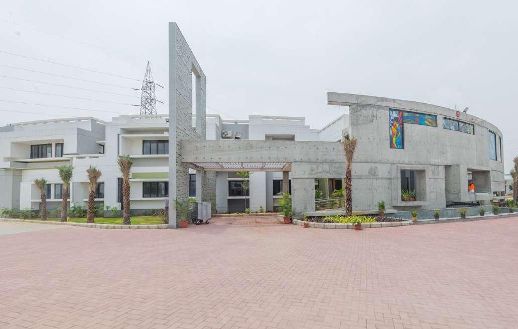
08 COMMUNITY HOSPITAL
The project aimed to depart from the typical monotonous design of hospitals, instead focusing on creating spaces that promote well-being and have a soothing effect. I was actively involved in Phase 2 of the construction process and contributed to the design of exterior spaces in addition to occupancy considerations.
The tall volumes of common areas were strategically designed to facilitate visual connectivity across all levels and to allow natural light to permeate the space. Additionally, the curved wall at the entrance serves as a welcoming element, inviting and easing the flow of occupants into the facility.
My role encompassed drafting and design documentation, assisting the project team with on-site progress, and coordinating weekly site meetings.
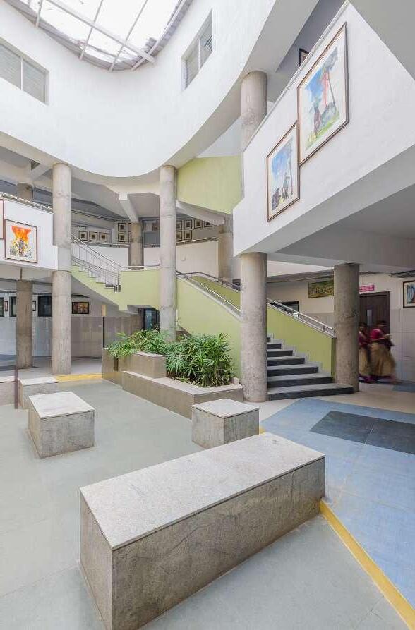
Top I Light-filled atrium/central courtyard
Bottom Left I Exterior porch wall expresses strong imagery
Bottom Right I Emergency block foor plan
26
professional work
TERRACE OPEN SLOPE SLOPE
DOUBLE ROOMS
27
Top I People court and lobby
Bottom I Curved front wall elevation with openings
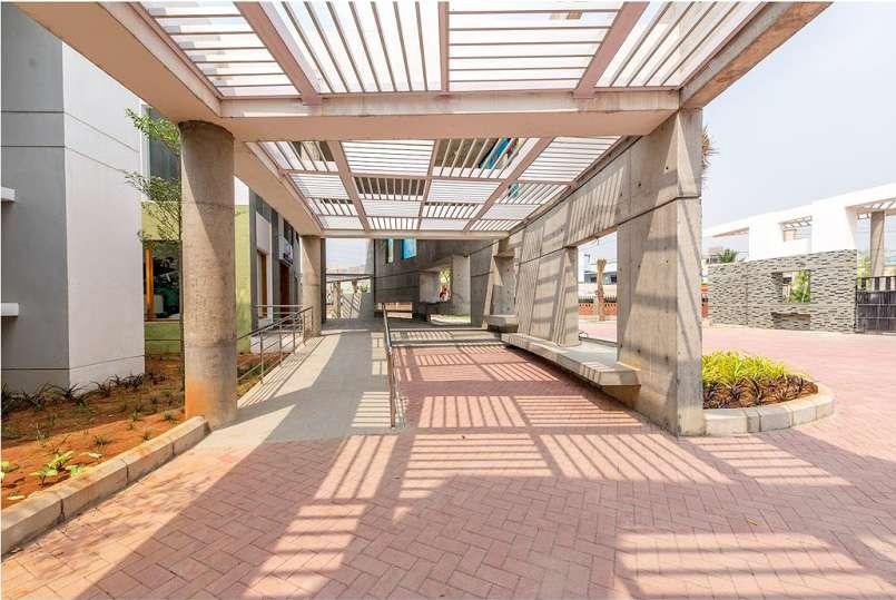
08 RETREAT
professional project
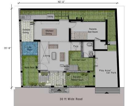
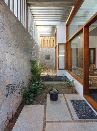
The residence serves as a serene retreat for a small family, emphasizing connectivity with the surrounding environment. Its design embodies minimalism, prioritizing well-ventilated spaces while showcasing integrated craftsmanship that enhances visual appeal.
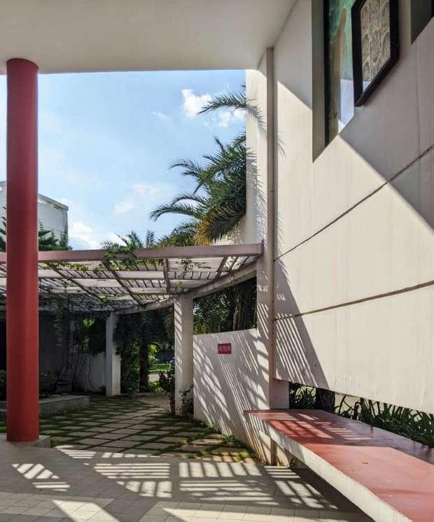
A narrow pathway, adorned with pergolas and paved with rugged granite stones, guides one through the property. The interplay of stone pergolas, granite-clad walls, and unfinished epoxy-finished flooring creates an intimate ambiance.
The interior spaces are thoughtfully connected to green courtyards and lush gardens. French doors open up to water features and pergolas constructed from exposed concrete, providing a captivating visual experience that seamlessly connects the home to the sea and sky beyond.
28
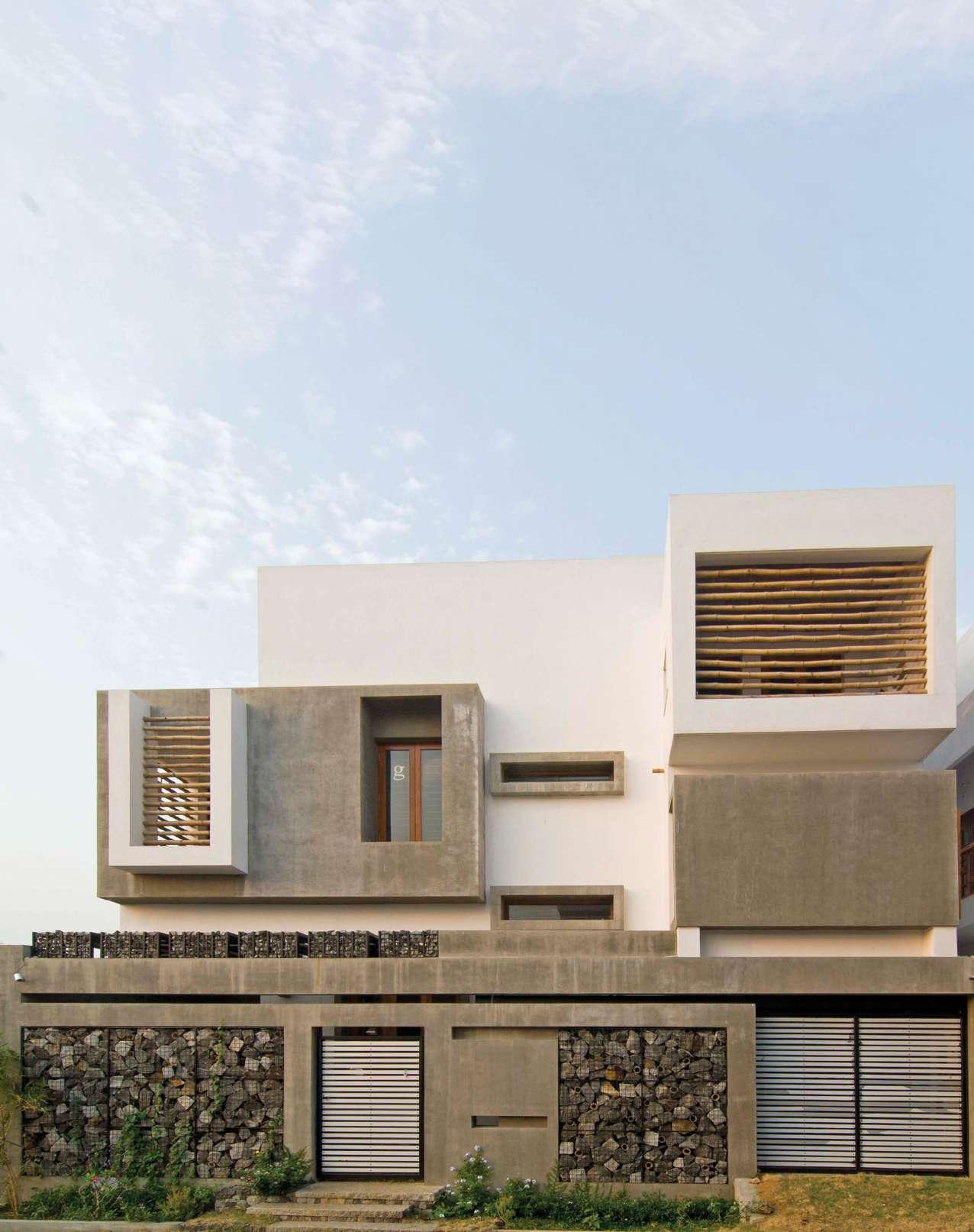
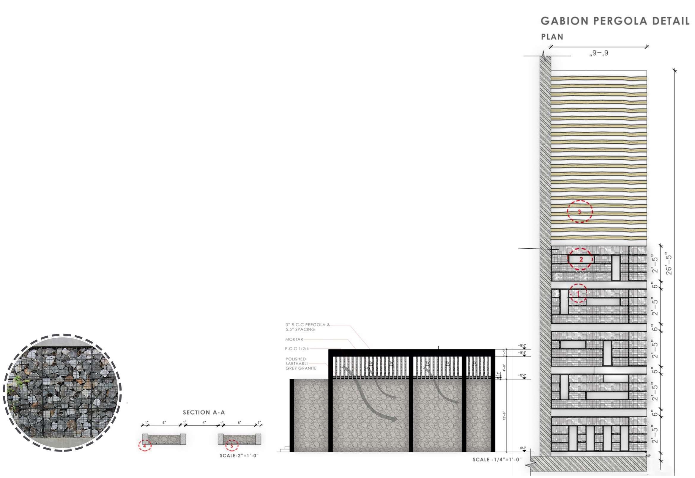
Top I Exterior Elevation Bottom Left I Gabion wall compound elevation
Gabion walls and bamboo pergolas introduce a sense of strength and character to the design, while the concrete flooring and stone walls contribute to the rustic aesthetics that delight the senses. The pergolas themselves are paved with natural granite stones, further enhancing the natural and tactile aspects of the design.
29
Top I Exterior Elevation
Bottom Left I Gabion wall compound elevation