


President: Anwesha Ghosh
Vice President: Ewan Butterworth
Foreword Timeline
Planes of the Week
AV 0603
AV 1303
AV 2003
AV 2703
AV 1704
AV 2404
AV 0105
AV 0805
AV 1505
AV 1906
AV 2606
AV 0307
Articles
Clear Air Turbulence
The Materials of the Future
How budget airlines remain competetive amonst a world of luxury
The Success Behind the Emirates Business Model
The Weirdest Fighter Jet of all time
The Forgotten Story of the Rotodyne
Drone Mechanics and Control Theory
The Future of Materials in Aviation
Winging it: The Beautfiul World of Wings
A (short) promotion of the imitation of avian flight mechanics in aircraft design
Anwesha Ghosh, Ewan Butterworth
Airbus A380
EHang EH 216-S
A-90 Orylonok
Boeing 737-10 MAX
General Dynamics F-111 ‘Aardvark’
Airbus A350
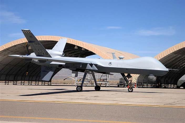
General Atomics MQ-9 ‘Reaper’
The MD Explorer
Boeing 777-300ER
Lockheed Martin MC-130
Boeing 747SP
Boeing X-51 Waverider
Ewan Butterworth
Anwesha Ghosh
Rithik Rachcha
Sachin Prakash
Keshav Sheshadri
Abhinav Malladi
Jawad Uddin
Sonali Prasad
Barret Marboh
Ewan Butterworth
It’s crazy to think how Aviation Society has blossomed from Ewan and I’s conversations about planes on the way to school to a full blown society full of people who are just as passionate about aviation! The society has been a pleasure to start, and the enthusiasm with which it was received makes all the effort put into it worthwhile. Said enthusiasm has permeated throughout the years and I’ve learnt so much from everyone who has been a part of it, from scramjet designs to materials that can heal themselves. I’ve met so many different people and nurtured friendships that I’ll cherish :) It’s provided the perfect avenue to direct all the “avgeekiness” (as Ewan quite aptly terms it) through!
This journal is the culmination of many late nights, confused messages, and hard work. It is our guide through what we’ve done this year, from the Planes of the Week that I’ve had the pleasure of writing for you (with the “dedication and passion” you all claimed, along with some magic) to a variety of articles on everything aviation. Take a tour through the fantastic talks we’ve had this year, and match them up to their respective planes, and you’ll unboard the ride as an enlightened, certified aviation geek. When someone asks what this society is all about, presenting this journal will just about sum it up! I sincerely hope you enjoy it, and that the society continues to fly high for many years to come :)
Anwesha
Ghosh
Aviation Society has been one of the best things to happen to me this year (which includes friends, F1 in Schools, Olavian Parkrun Tour and the Iceland trip, to name a few (so a strong lineup)) because I have had the chance to practise in full my avgeekiness and add even more knowledge about the aviation industry to my mind along the way. It’s crazy to think that it all started from Anwesha texting the idea to me on WhatsApp – I would never have had the courage to make the society myself, so I have really just hitched onto the back of Anwesha’s bandwagon of AvSoc as Vice President. I was going to write a longer article of my own for the journal, and it is in the works as I write this, but the time is nigh for the journal to be submitted so I have cut it down to just the owl, which I hope is an interesting enough bird on its own – expect the full version next year!
It has been my pleasure to write the Plane of the Weeks and give the talks when I have had the chance to at the society. I would say that it hasn’t been too bad a first year for us, compared to the other start-ups of this year (Kirollos won’t mind me giving a mention to Machine Learning Society here (go to it, it doesn’t get the attendance that it deserves)). So, thank you to everyone who has come to the Wednesday talks, I do hope is that Aviation Society continues to prosper for years to come, and enjoy the journal!
Ewan
Butterworth
Editing this journal was a challenge, but worth it. I thank everyone who dealt with my relentless messages, and who were willing to take their shots at the challenge by trying their best to edit. The platform we used was fiddly, though through plenty of encouragement, we’ve managed to create a solid journal that accurately represents what we’re all about.
Thank you to Abhinav, who helped finish up editing! Here’s a message from him...
“Editing this was a very confusing but fun adventure! I love this Senior Aviation Society and this journal came out to be a wonderful read.”
AV 0603: Can planes get any bigger?
Ewan Butterworth AV 2003: How planes fly
Keshav Sheshadri AV 1704:
How to design a supersonic aircraft
Anwesha Ghosh
AV 1303: Are planes becoming redundant?
Shreshth Mishra AV 2703: Alternative Fuel Sources
Edward Hawkins AV 2404: Materials and plane construction
Sonali Prasad
AV 0105:
Drone Mechanics
Jawad Uddin
AV 1505: The Mystery of the MH370
David James Wu AV 0307:
Scramjet Intake Design
Ewan Butteworth
AV 0805:
The Best Attack Helicopter in the World Oleg Tereschenko
APOLLO-2406: Angle of Attack
Sonali Prasad

Weekly mini articles in reference to the respective talks; AV0603 to AV0307.
Welcome on board the plane of the week, Aviation Society!
A plane that seemed to circle around today’s talk was the Airbus A380, crowned the world’s largest passenger aircraft. It has been dwarfed by the Antonov An-225 Mriya; however, this is a strategic airlifter that does not have to grapple with the safeties of passengers and comfort. Thus, let’s take a closer (or wider) look at the reigning A380...
Facts + Figures:
Wingspan: 80m
Engine types: Rolls-Royce Trent 900, Engine Alliance GP7000
Top speed: 1,185 km/h
Length: 73 m
Range: 15,200 km
First flight: 27 April 2005
Cruise speed: 903 km/h
Price: $445.6 million (£349.37 million)
Max Passenger Capacity: 853
If you’re interested in the A380, here’s Airbus’ rundown on it, with some cool stuff about the new materials and technologies used (with mentions of the composite materials we touched on!): https://www.airbus.com/ en/products-services/commercial-aircraft/passenger-aircraft/ a380
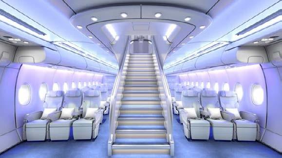
A look inside...
With two full-length decks and mores seats than any other aircraft, the A380 offers plenty of legroom....
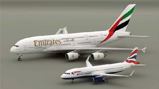
It’s a bird... no, a plane! Visualising such a massive plane is difficult, so here ‘s a photo comparing it to the also popular Airbus A320:
Make sure your seatbelts are fastened for the plane of the week, Aviation Society!
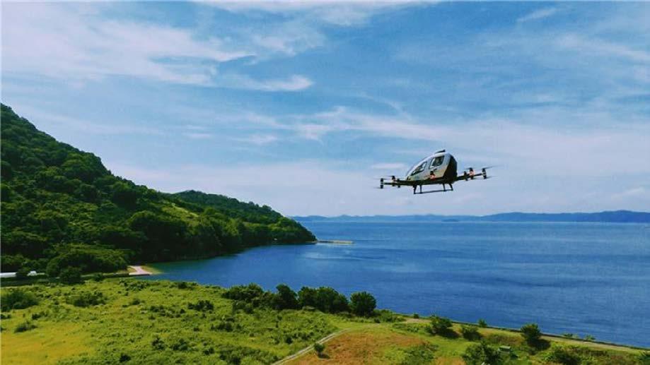
While Shreshth Mishra was debating whether planes were becoming redundant, he mentioned the new Chinese ‘air taxis’ that have been developed, promising us an exciting future bordering on sci-fi. These ‘air taxis’ are generally referred to as eVTOLs (electric vertical take-off and landing aircraft), and have been popping up all around the world, from California to Munich. Guangzhou EHang Intelligent Technology Co. Ltd has made significant progress in iterating their eVTOL designs towards the newest EH 216-S.
The EH216-S is a two passenger eVTOL multicopter production model aircraft made for advanced air mobility (AAM). EHang have entered service in China for aerial cinematography, photography, emergency response, and survey missions.
As of January 2020, EHang has reported that for the EH216-S aircraft, over 2,000 passenger flight tests have taken place including flying in winds up to 70 km/h (44 mph), in fog and with low visibility situations which have been around 50 m (164 ft). EHang is also seeking U.S. Federal Aviation Administration (FAA) approval for their aircraft and their first U.S. flight test took place in January 2020.
Propellers: 16 bladed
Batteries: Shenzhen Injoinic Technology Co. Ltd. (Inx)’s solid state 17kWh batteries (recharge time 120 minutes)
Top speed: 130 km/h
Length: 5.61 m
Range: 35 km
First flight: 28 December 2023
Cruise speed: 100 km/h
Price: $410,000 (£320,203.85)
Max passenger capacity: 2
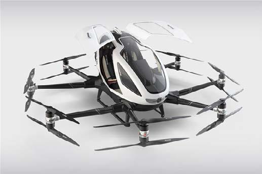
The aircraft, quite unfortunately, does not look like a flying taxi with wings. In fact, it doesn’t have an easily categorised shape - they don’t follow the design of a standard aeroplane and can’t really be classified as a helicopter. The best way to describe them would probably be as some sort of inverted helicopter, with arachnoid arms extending out from the bottom complete with propellers.
The EH 216-S boasts gull-wing doors - which are basically doors that flap up, like a seagull’s wings. Other than looking cool, these make it more convenient to get in and out of the aircraft. The fuselage is made of carbon fibre composite for high strength to low weight ratio. The aircraft has fixed skid landing gear, which is just are the handle shapes at the bottom, which help ensure a smooth landing.
If you’re interested in the EH 216-S, here’s a full rundown on it that fully covers the timeline of manufacturing and development and provides an extensive list of all its specifications and prototypes. It really has it all: https://evtol.news/ehang-216/
Anwesha
Ghosh
Keshav Sheshadri’s informative talk today explained Bernoulli’s Principle and subsequently established, very well, how exactly planes fly. Indeed, it has brought about an idea for this week’s plane, as this particular plane exploits a set of mechanisms including Bernoulli’s Principle.
Now, don’t be fooled by the ‘A’ at the beginning of its name - today’s aircraft is not an Airbus, though it is partially European. It’s Russian , and incredibly peculiar.
The A-90 Orylonok is a Soviet-era ekranoplan - a ground-effect vehicle. It is very barely a plane in fact but an incredible feat of engineering, because it spends most of its time hovering tens of feet above water.
Ground effect in aviation is a phenomenon which occurs when an aircraft and its wing are flying closely above a smooth, flat surface. In essence, because the wing is so close to the ground, air flowing beneath it is compressed between the floor and the wing, increasing the static pressure below the wing to an even greater amount than the wing will already have been doing. This results in an enhanced lift effect (that’s not an actual term, just sort of summarises it well ), and means the wing becomes very good as producing lift. If you’d like to read more, here’s a link to a good paper - https://apps.dtic.mil/sti/tr/pdf/ADA361836.pdf (head to page 5).
Thus, the A-90 is designed for this effect, so its peculiar appearance is justified:
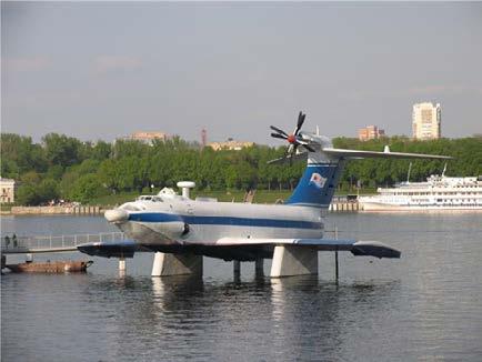
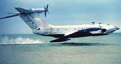
Developed by the Central Hydrofoil Design Bureau, the A-90 was designed for transport and amphibious military use - yes, it has wheels. 4 of the models were built, one of which was used purely for testing:
Payload: 28,000kg/150 passengers
Length/Wingspan/Height: 58.1m/31.5m/16.3m
Max takeoff weight: 140,000kg
Power: Look at the Wikipedia, it’s a lot: (https://en.wikipedia.org/wiki/A-90_Orlyonok#Specifications_(A-90))
Maximum speed: 220 knots (250mph)
Altitude ceiling: 9,800ft
Range: 1,500km
Aircraft specialising in the utilising of ground effect are truly fascinating. Another incidence of the application of ground effect and the sealing effect of the floor is in Formula 1 cars, to produce the exact opposite of what aircraft do - downforce.
Ground Effect is a concept very useful and just cool as well to know, so I recommend further explorations, particularly into its application in motorsport! As for the A-90, it was ultimately just a cool accessory of the Soviet Union, with it never really coming into full use. Only one exists now in the Museum of the Navy, Moscow, so it isn’t incredibly well known or well seen - which is the beauty of Planes of the Week.
Ewan Butterworth
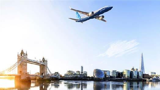
Boeing 737 MAX 10: The pioneer of new SAF technology
With the skies clear, get ready for this week’s plane of the week, Aviation Society!
While Edward Hawkins talked of the feasibility of new fuel sources for a more sustainable future, he mentioned the historic flight of the Boeing 787 with 100% Sustainable Aviation Fuel from London to New York JFK on the 28th of November 2023. It marked a significant moment in the movement to making sure aviation can survive in a future without fossil fuels, with a growing awareness of the industry’s environmental impact. The SAF used was made from waste products and could deliver CO2 lifecycle emissions savings of up to 70%, whilst being a ‘drop-in’ fuel that is compatible with today’s engines, airframes, and fuel infrastructure - hence minimising both economic and environmental costs in the long run.
In terms of what the SAF was actually made of (so, what waste products), it was a unique dual blend of 88% HEFA (Hydroprocessed Esters and Fatty Acids) and 12% SAK (Synthetic Aromatic Kerosene). The HEFA is made from waste fats while the SAK is made from plant sugars, with the remainder of plant proteins, oil and fibres continuing into the food chain.
We seem to have altered course a bit, so let’s get back on track to the Boeing 737 MAX 10the plane that facilitated such a vital advancement. The 737-10 is part of the greater 737 MAX family, which is based on earlier 737 designs, but better (more on that later). Out of the 737 MAX family, the 737-10 is the largest. However, the 737 MAX 10 has not yet been approved by the US Federal Aviation Administration. The primary competition would be the Airbus A320neo family.
Wingspan: 35.9 m
Engine type: CFM InternationalLEAP-1B
Top Speed: 975 km/h
Length: 43.8 m
Range: 3,100 km
First flight: 18 June 2021
Price: $150 million (£119.04 million)
Max passenger capacity: 230
A closer look at the design...
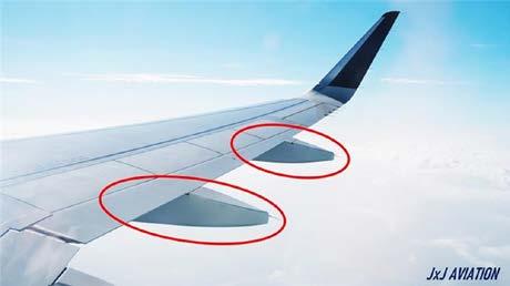
The 737-10 uses a split tip winglet (pictured on the next page), that reduces vortex drag, which is essentially when the high pressure below a wing spills up over the wing tip into the area of lower-pressure air above (as mentioned in Keshav Sheshadri’s talk last week!). Since this maximises lift, it improves fuel efficiency.
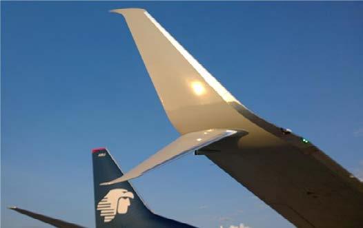
Split tip winglet
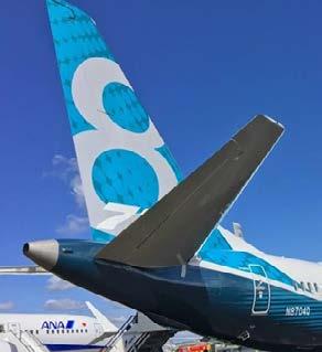
Re-countoured tail cone
Other improvements from previous 737 include a re-contoured tail cone, which is essentially just the structure at the back of the aircraft that provides stability during flight - like the feathers on a badminton shuttle. By recontouring this, the plane has increased aerodynamic capability, and hence, increased fuel efficiency. The tail cone is pictured above.
We’ve been discussing the excellent design features, but what does the plane look like as a whole? How are we to identify it? Here are some pictures, to answer those questions
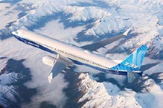
https://www.boeing.com/commercial/737-10#videos - the official Boeing website has much to say on technical specifications and the manufacturing behind the plane.
https://www.ainonline.com/aviation-news/air-transport/2023-11-05/latest-boeing-ecodemonstrator-studies-tackle-safs-contrail talks about how NASA, Boeing, GE Aerospace and German aerospace research centre DLR are researching the feasibility of SAFs using the 737-10.
https://www.boeing.com/features/2023/12/737-10-dc-8-team-up-to-test-sustainable-fuel -> official report from Boeing on the research with the 737-10 into SAFs
Anwesha Ghosh
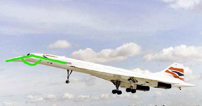
I suppose you’d be expecting the Concorde for this week, and naturally so – Anwesha’s talk included in large part the contribution the development of the Concorde made to commercial aerospace and supersonic aircraft as a whole. However, another aircraft she mentioned caught my interest even more than the Concorde, and that was the F-111:
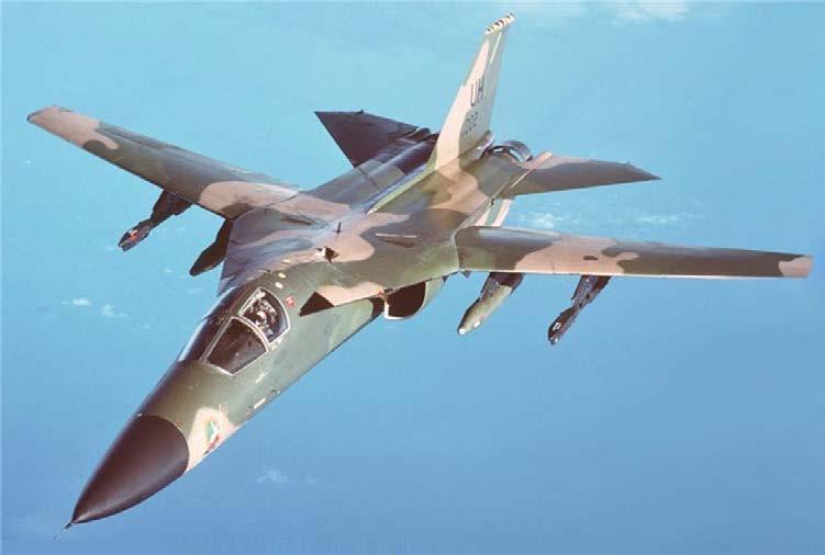
The F-111 is named under the standard of the United States Tri-Service aircraft designation system (it really isn’t as complicated as it might first appear), which is used to name all US military aircraft, of which there are many. For example, the X-59 which Lockheed Martin recently released has the ‘X’ because it is an Experimental aircraft. The F-111 is named with an F because it is a Fighter aircraft – see, not that complicated (here’s the link to the Wiki for the full beans, and reading a bit more does make it a bit complicated, but oh well: https:// en.wikipedia.org/wiki/1962_United_States_Tri-Service_aircraft_designation_system).
Now, why did the F-111 catch my attention? Because of its innovation, particularly its flagship role in the pioneering of technologies on fighter jets found today – specifically, the:
• Variable sweep wings (the first production aircraft to have these!!)
• Afterburners
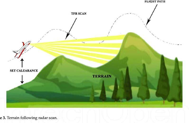
• Automated Terrain-Following Radar (TFR)
So, I’m going to go through these three:
As explained by Anwesha, variable sweep wings can be utilised on supersonic-aircraft to aid in optimising the L/D (Lift to Drag) ratio of aircraft requiring high-performance at both very high speeds and comparatively lower speeds (low subsonic speeds), which of course a fighter aircraft will fall into – as a reconnaissance and escort aircraft, it would have the ability to shoot off at a moment’s notice, whilst also having the manoeuvrability to give it the upper hand in close combat situations, and when landing at super low speeds (on aircraft carriers most likely, especially in the case of the famous F-14 https://en.wikipedia.org/wiki/Grumman_F-14_Tomcat). Particularly in the aircraft carrier environment, variable sweep wings are also convenient for storage: more planes can be fit side-by-side with shortened wingspans.

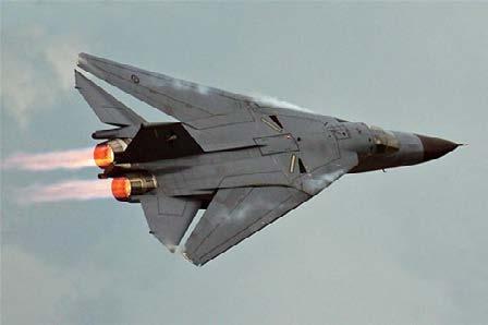
(Above left: F111 with wings swept back) (Above right: F111 with afterburners)
Afterburners are a term you’d get from football commentators when Vinicius Junior “turns on the afterburners” because he’s so fast. This connotation of intense acceleration and speed is as a result of the function of afterburners on aircraft.
Afterburners are applied to a jet engine as a form of secondary combustion at the rear of the jet, where a fuel pipe is linked to the back of the jet and feeds fuel to ignite the exhaust coming out of the jet, giving the engine an extra amount of thrust and producing that iconic flame out of the back.
Afterburners are obviously useful where an aircraft needs more power, and they are a good alternative to the option of just making the engines bigger to get more power, which comes up with all sorts of packaging issues. However, because they consume so much fuel, afterburners are set at 100% throttle on a pilot’s controls and, thus, are used sparingly.
When you search for TFR in aviation, you’ll probably come up with “Temporary Flight Restriction” which isn’t what this TFR is. TFR is quite interesting, because it is a system which tracks the best route for an aircraft to stay at a certain altitude above the terrain for low stealth flying – it’s essentially what they did in Top Gun Maverick, flying as low as possible to avoid the radar detection of enemy SAMs (Surface to Air Missiles).
TFR uses a vertical pencil beam of scanning signals to map out the terrain below and infront of the aircraft. Doing this means it can produce a flight path that keeps the aircraft at a set altitude above the ground (usually between 1000-4000 ft), which is very useful to the pilot in maintaining undetected.
Something to realise with TFR is its difference from Terrain Avoidance Systems and Threat Avoidance Systems, both of which are more complex, and kind of take the coolness out of TFR. Terrain Avoidance Systems (not to be confused with TAS meaning True Air Speed ) scans along both the vertical and horizontal planes where TFR just scans along the vertical, and it actually means that Terrain Avoidance Systems are probably closer to what they used in Top Gun – think of TFR as a roller coaster path, and Terrain Avoidance Systems as a snake path (here’s a good link to read further into the two, as well as Threat Avoidance: https://www.sciencedirect.com/topics/engineering/terrain-following)
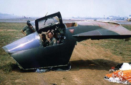
Another pretty cool feature (enough to mention) is the crew escape capsule where you would normally have ejection seats. In the event that the F-111 was shot down, the crew could eject in the capsule and be protected much better from the wind smashing against them as they travel at supersonic speeds out of the aircraft compared to the ejection seat.
So, now onto the actual aircraft:
There is a lot of background as to the reasons for developing the F-111, and so I will just stick the Wikipedia link in if you want to read it (https://en.wikipedia.org/wiki/General_Dynamics_F-111_Aardvark#Early_requirements).
In simple, the USAF needed a fast strike aircraft, so they made the F-111. A Fighter variant for the Navy (the F-111-B) had its development fail, and the earlier referenced F14-B Tomcat became the F-111’s predecessor on the fighter side, with much of the tech development on the F-111 used on the F14-B, a testament to the importance of the F-111’s development .
The F-111, had many variations, mainly to include updated versions with newer technologies or for different countries’ air forces (specifically the UK and Australia), as well as variant specialised in tactical bombing (in the process of typing this, I found this cool website http:// www.f-111.net/index.html, although Google says it’s not secure, so I guess access at your own risk – don’t, and miss out on all of the fancy F-111 knowledge ).
Notable uses in service of the F-111 include:
• Vietnam War – where the principle of “speed is life” was key, the tech of the F-111 proved crucial in the success of the US Air Force in Vietnam. The ability, with its TFR system, for the Aardvark to fly as low at 200ft above the ground at close to 500 knots (575mph) meant it was able to complete “one pass, haul ass” effectively: its afterburners gave the oomph for a quick dash away from enemy missiles.
• Gulf War (Operation Desert Storm) – dropped over 80% of the war’s laser-guided missiles, and had the highest survival rate of any US aircraft at 32 successful runs to every 1 aircraft shot down.
Many, so (again) here’s the Wikipedia link (https://en.wikipedia.org/wiki/General_Dynamics_F-111_Aardvark#Specifications_(F-111F)). For you nerds, take a close look at the aerofoil stats, and the variation between the root and tip of the wings on the F111 – they will link with the functionality of the variable-sweep wings and (for even more inquisitive minds, I don’t how) sweep theory.

Yeah, the last of the F-111s went out of service in 2010, so the only place you might have a chance of seeing them would be at an airshow . I recommend Farnborough https://www. farnboroughairshow.com/
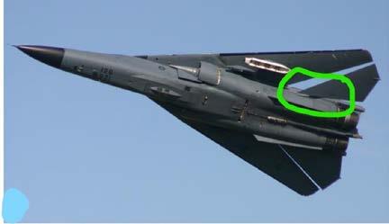
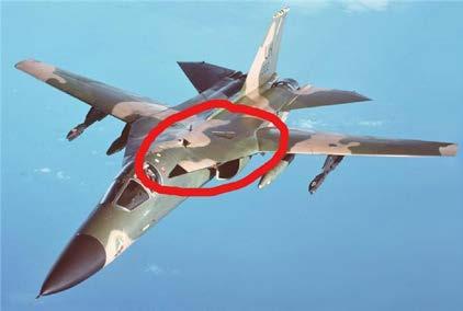
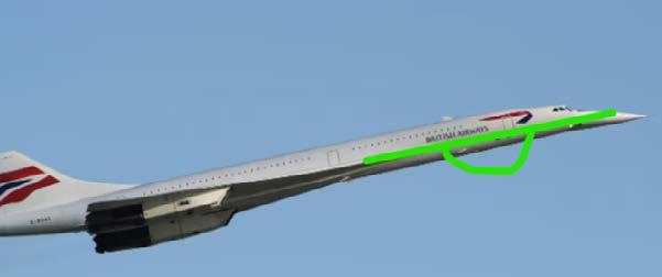
In all seriousness though, the F-111 if you were to see it from the ground would either have its wings swept in like in the photo below, or out. You could potentially look for almost squared-off wing tips, a distinctively thin nose, the thin joining between its elevators and fuselage (circled in green) and its chunky lat muscles (you know what I mean) circled in red in the second photo:
The F-111 is great to know for a bit of trivia as well, on a final note. Thanks for reading!
Ewan Butterworth
Extra:
If you were disappointed with the lack of Concorde, here’s a fun fact (Edward Hawkins!)
The Concorde had to take-off and, more notably, land at very high angles of attack – the main reason for it having the distinctive droop nose, so the pilots could actually see the runway. This was because of one of the aerodynamic principles upon which the Concorde’s wings were designed.
To explain first is the idea of a swept wing encouraging flight at supersonic speeds, and it is a bit long. To simplify (greatly), sweeping the wing enables the aircraft to fly to higher values of Mach without shock waves forming on the upper surface of its wings – shock waves cause drag (wave drag) which we don’t like.
The Concorde is a delta wing aircraft, giving it swept wings and a super long connection of wing to fuselage, to the point that it is basically part of the fuselage, making it ideal for prolonged supersonic flight – of course, the Concorde is designed for supersonic efficiency. As a result, its engineers used the ability of high-sweep delta wings to create large amounts of intense vortices on their upper surfaces at high angles of attack to solve the issues with the ‘supersonic-centric’ design that limited its performance at conventional speeds and angles of attack. The vortices created areas of intense low-pressure above the wing which, as explained previously by Keshav’s talk, created the lift required to land the aircraft at safe speeds.
Sonali Prasad’s talk really was an excellent guide through the history of materials in plane construction – with everything from the Wright Brothers’ inclination to use wood over aluminium, to Bristol University’s research into self-healing materials. A touch less futuristic, but imperative in flying longer distances with less fuel, is the use of composite materials –something that the A350 XWB flaunts, with the use of ~52% composites in its airframe, as shown in the infographic below:
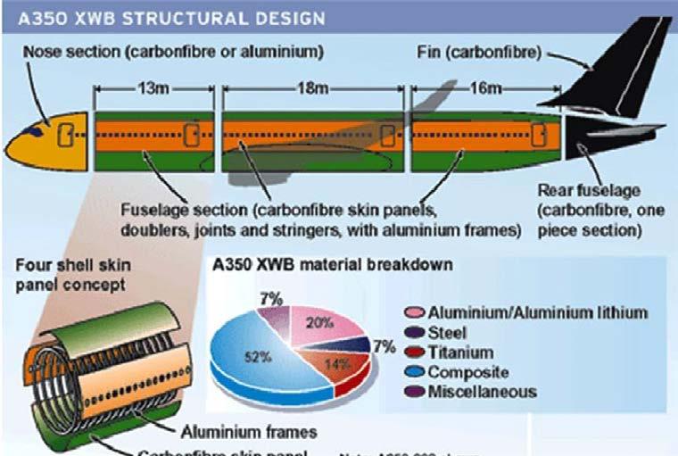
If we are to break down what ‘composites’ are being referred to, CFRP (Carbon Fibre Reinforced Plastics) as mentioned by Sonali, would come to mind. Her talk excellently explained what these were: “microscopic carbon fibres embedded within resin”. Under a microscope, the CFRP looks almost cellular:
But macroscopically, it lends itself to the smooth, corrosion resistant planes we are familiar with.

Wingspan: 64.75 m
Engine type: Rolls-Royce Trent XWB
Top Speed: Mach 0.89 (950 km/h)
Length: 66.8 m
Range: 17,964 km
First flight: 23 April 2018
Cruise speed: Mach 0.85 (903 km/h)
Price: $317 million (£136.52 million)
Max passenger capacity: 440
If we are to move past materials, the A350-900’s wing design morphs in flight to maximise aerodynamic efficiency and push that bit further with the same amount of fuel. This ‘metamorphosis’ emulates how bird wings have evolved over millennia to maximise lift and minimise drag – another example of how biomimicry may pioneer the future of aviation. How the wing morphs is via a variety of mechanical features, one of which are the new adaptive dropped hinge flaps, as shown bottom left. These help generate lift at lower speeds, which allows the aeroplane to fly without the risk of stalling, and so are especially useful during both takeoff and landing.
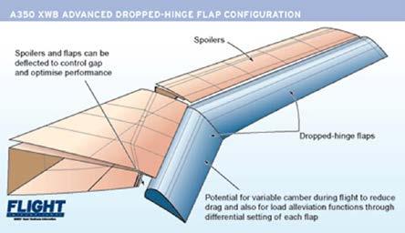
To improve efficiency at higher speeds, the A350 XWB can deflect its wing flaps differentially, optimising the wing profile and providing better load control. More gains are made using myriad little touches like refining the shape of some of the fairings (the curved bits at the bottom of wings, shown above right), using curved windshields and low drag engine nacelles (the containers the engines are housed in). These, and many other small design modifications help the wing slip through the air better and keep the noise down.
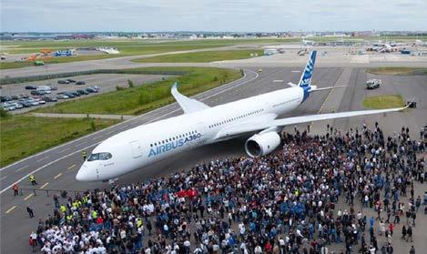
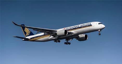
Look up! Not the clouds, and certainly not gullibility...
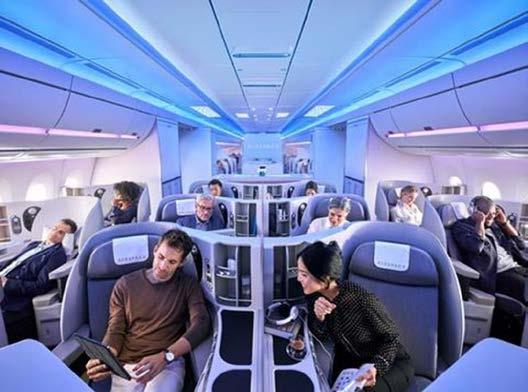
As is tradition, let’s step back and look at the plane as a whole, in all its glory as the efficient giant that quietly covers the longest flight (the Singapore – New York flight route, at 15,348 km long).
Since the flight is so long, the interiors are pretty bougie as well, with 67 pod-style business-class seats and 94 premium economy seats, and no regular economy seats.
The official Airbus website was ever helpful: https://aircraft.airbus.com/en/aircraft/a350-cleansheet-clean-start/a350-900
Virgin Atlantic also gives a really comprehensive rundown of the plane: https://flywith.virginatlantic.com/gb/en/stories/the-airbus-a350-a-quiet-efficient-giant.html#:~:text=To%20improve%20efficiency%20at%20higher,and%20low%20drag%20engine%20nacelles.
And an abstract that goes into much more detail about the ‘wing movables’ of the A350: https://www.icas.org/ICAS_ARCHIVE/ICAS2014/data/papers/2014_0133_paper.pdf
Anwesha Ghosh
ULR - Ultra Long Range
XWB - Xtra Wide Body
To explain the XWB configuration we need to look at why the A350 was being made in the first place - to counter the success of the Boeing 787. When Airbus first released some stats for a potential A350 however, potential customers weren’t especially happy with the thin fuselage that limited the number of seats abreast and thus the number of passengers that could get onto the aircraft. As such, they redesigned to the XWB, expanding to 10 seats abreast, compared to about 8 initially increasing capacity from 300-350 passengers to 440-475 passengers, and satisfying airlines in search for an ultra-efficient long-haul airliner with a higher passenger capacity than the 787 and a greater efficiency than the 777, which were both absolutely wiping the floor with the competition before the A350 came along.
Seeing as Jawad so thoroughly went through the basics of computer control of a drone, this week’s Plane of the Week is another Unmanned Aerial Vehicle (UAV), though on a much more militaristic theme.
Aside from it being topical in relation to Jawad’s talk, the General Atomics MQ-9 “Reaper” is also topical in the sense that its use is increasingly significant in the world’s conflicts, specifically the ones the US are involved in – the war in Ukraine, and combatting the Houthi military in Yemen, Iraq and Syria.
As aforementioned, the MQ-9 is a UAV, a drone, which can both be remotely controlled or be autonomous. It’s primarily used for reconnaissance, and naturally is designed for stealth as a result. However, the scary bit is that they are occasionally fitted with weapons, though MQ-9s don’t turn into gunships. Instead, they are usually fitted with 1-2 missiles, though they are able to carry up to 8 missiles. Likely the most famous use of force by the Reapers were in the War on Terror in Pakistan (https://en.wikipedia.org/wiki/Drone_strikes_in_Pakistan).
The MQ-9 is a development upon the MQ-1 Predator, also by General Atomics (who, obviously, are military contractors, working primarily for the US military and USAF (US Air Force)), and an inspiration for the MQ-20 Avenger (the reason I’m not then talking about the Avenger is because it hasn’t actually been used yet ). It is essentially a family of military aircraft with terrifying appearance – I personally think they look like the alien from Alien:

The engine powering the MQ-9 is a 900hp turboprop engine by Honeywell. Thus, the Reaper isn’t a speed demon as one would expect from a US military aircraft, and its cruise speed is about 170 knots, with the highest it has ever really gotten to at 260 knots. It has a service altitude ceiling at 50,000ft, which is barely anything for a reconnaissance aircraft, and it is usually operated at 25,000ft.
The Reaper’s overpowering strengths are its size, its ability to collect data, and the fact that it doesn’t have a pilot in it. It is a very successful aircraft, with over 300+ having been built, and more on the production line to be sent out to their orders.

Some say the camera is so good, it can read a license plate from 2 miles away, and that it has the radar footprint… of a fly.
I made that last one up (though the F-35 fighter jet does have the radar footprint of a bee, so I’m probably not far off), and the reference might be a bit obscure (Top Gear is the best ), but the overarching idea is that it is super sneaky. It’s so full of reconnaissance tech that I’ll just list the acronyms below and let you guys do your own research:
- Raytheon AN/AAS-52 multi-spectral targeting sensor suite
- Lynx Multi-mode radar (with Synthetic Aperture Radar (SAR) which is actually quite cool - https://www.earthdata.nasa.gov/learn/backgrounders/what-is-sar and https://en.wikipedia.org/wiki/Synthetic-aperture_radar)
- Ground Moving Target Indicator (GMTI)
- Dismount Moving Target Indicator (DMTI)
- Gorgon Stare (only really for testing though), incorporating ARGUS-IS
Most of this tech is compacted into its dome-y, alien-like head – the rest likely fuel, but that’s classified (or I just can’t be bothered to comb the internet for a pdf with a cross-section of the Reaper).
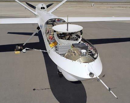
The fact that the Reaper is without a pilot in it but is instead connected to a pilot via an antenna and radio signals is an interesting point for discussion.
As of late (though to be honest as of a while back as well) lots of militaries have been publicly showing their interest in unmanned combat aircraft. It prevents loss of life, removes design requirements and restrictions surrounding the pilot being there and potentially overcomes the physical and mental constraints of a human – an AI would happily pull 11G where a human would instantly pass out – allowing fighter aircraft to make ever more daring manoeuvres, giving them an edge over the competition.
The counter argument would come from a movie line, TopGun-esque: computers don’t have the human flair, or the human morality. On a more formal point, the argument is also that putting a multi-million-dollar, absolute monster of a fighter aircraft in the full control of an AI spells trouble – one only needs to watch iRobot to get the heebie geebies.
Of course, you should know what I’m about to copy and paste: https://en.wikipedia.org/wiki/General_Atomics_MQ-9_Reaper#Specifications
A good thing to note is that the Reaper is no small plane: 20 metres wingspan is from the door of the Holyoak Room to the door into the Humanities block! In fact, to put into perspective, the wingspan of a F-35 fighter is 11 metres, and on the F111 (from two weeks ago) is 19 metres, so the Reaper trumps both!
On a more poignant ending note, let’s hope none of us are at the pointy end of a MQ-9 Reaper. It is a truly lethally effective aircraft when set up to be.
Instead, let’s look to Oleg’s talk next week, (unless it gets pushed back another week...) which will carry on this military theme, and something you might be able to link to Jawad’s talk - but I’m not going to spoil it!
Ewan Butterworth
MD Helicopters MD Explorer: a brief lesson in flu-
The Kamov KA-52 of Oleg’s talk from today is different from a more conventional helicopter layout in that it doesn’t have a tail rotor, instead using a pair of primary rotors spinning in opposite directions to counteract the yaw produced by the rotor above/below it, and the layout owes to some very useful attributes for an attack helicopter.
This highly intriguing feature brought to the front of my mind another set of helicopters of similar concept: NOTAR (No Tail Rotor) helicopters, and specifically the McDonnell Douglas (MD) Helicopters MD Explorer.
Where is the MD Explorer in use?
Most notably for us, London’s Air Ambulance own two MD Explorers (though they are soon to be replaced), one since October of 2000 and the other since January of 2016. They usually operate the helicopters with one active for the day and one on standby as back-up. The two helicopters are named Walter and Rowan, after the relatives of the winner of the competition to name the helicopters, which I think is quite sweet!
What makes the MD Explorer special?
The MD Explorer has no tail rotor and, unlike the Kamov from Oleg’s talk today, has only a singular primary rotor. Naturally would come the question, “Well how does it stabilise itself then?”.
NOTAR helicopters make use of a clever mechanism which combines the Coanda Effect and the Magnus Effect. Anyone who does F1 in Schools should know exactly how these two work, but for anyone who doesn’t, here’s a summary:
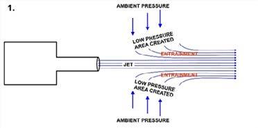
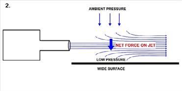
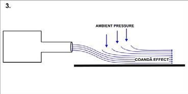
The Coanda Effect is the tendency of a jet of fluid emerging from an orifice to follow an adjacent flat or curved surface and to entrain fluid from the surroundings so that a region of lower pressure develops.
A well-debated effect in the field of fluid dynamics as to how exactly it works.
Firstly, one must understand the fundamental that, for a fluid (liquid or gas), a region of high-pressure fluid will try to balance itself out by moving to a low-pressure fluid – like diffusion.
After that, the idea is:
1. A jet of fluid will entrain (i.e., suck in) fluid from its surroundings because, as it travels, it leaves a trail of a region of low-pressure fluid behind it, which the surrounding air will move in to fill.
2. When this jet of fluid then gets close to a surface, it will entrain fluid from between the jet and the surface.
3. As there is a limited amount of fluid between the jet and the surface, a low-pressure region will thus form between the jet and the surface. As a result, the jet is sucked down toward the surface.
It’s the effect that makes a table tennis ball seem to float in midair when it is blown at an angle with a strong hairdryer! But, importantly, a big misconception is that it explains how water curves around a spoon – this, unlike the tennis ball, has water entraining air, which is a lot more difficult to make happen (because water is much denser than, and obviously isn’t, air). Instead, water curving around a spoon is more a result of the effects of water tension. Also, be careful when considering things like aircraft wings – things might just change when the air is still, and the wing is moving through the air, because it means the air is no longer a jet of fluid. Do more research, I recommend!
Credit for the photos: By Cruithne9Own work, CC BY-SA 4.0, https://commons.wikimedia.org/w/index.php?curid=53242227
The Magnus Effect is particularly relevant to F1 in Schools because it involves how a jet of fluid reacts when it meets the side of a rotating cylinder (so, in the case of F1 in Schools, the wheels!). It is almost perfectly explained in the diagrams you can find, but here it in words:
1. A surface has friction (obviously, unless you’re doing Year 1 Mechanics…).
2. Thus, if it is moving in the opposite direction to the one the fluid is travelling in, it will exert a greater amount of friction on the fluid, and vice versa for a surface moving in the same direction.
3. This can be seen around a rotating cylinder: say it is rotating anticlockwise, with the fluid coming from the left. The fluid going towards the bottom of the cylinder will experience less friction, and thus will travel quicker around the cylinder, and vice versa for the top side.
4. Thus, it is seen that the jet of fluid will be bent net upwards after encountering a rotating cylinder.
Credit for the photos: Me >:)
How are these effects used on the helicopters?
First, note where the tail boom and primary rotor on a generic NOTAR helicopter are:
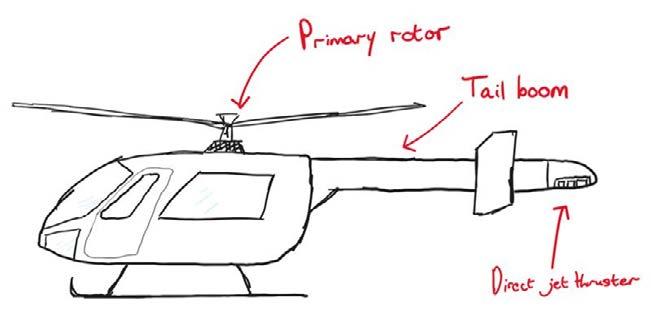
This is where it gets a bit complicated: How a NOTAR helicopter works is (and read very carefully),
1. The primary rotor washes air down (as is the function of every rotor, to provide thrust).
2. Some of this air is washed onto the tail boom.
3. Here, there are two routes the air goes. One is around the tail boom; the other is into an intake where the tail boom connects with the main body of the helicopter:
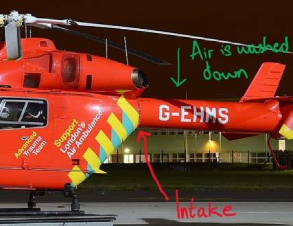
Intake:
1. The air is sucked into the intake by a turbine which inhabits the forward section of the tail boom.
2. This turbine blows air down the tail boom in a spiral pattern. According to Bernoulli, this air, as it is moving fast, is low pressure air.
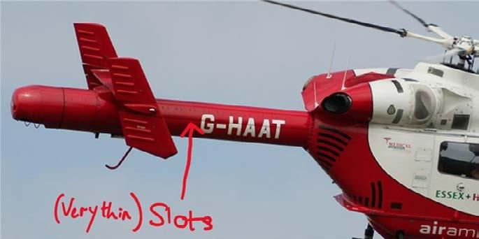
3. The air blown down the tail boom then either leaves the slots at the side of the helicopter, or the direct jet thruster out of the back:
4. The thin slots let air out in a way that means they stick to the surface of the tail boom. The air let go adds a lubrication layer to the one side of the tail boom, allowing the air to flow faster down one side than the other (emulating the MAGNUS EFFECT!!!!)
5. A common misconception about the direct jet thruster (where the rest of the air goes) is that it is the primary source of thrust – though this is partially true, it is primarily used to back up the thrust created by air flowing around the tail boom, as a more manoeuvrable option for thrust, mostly to help with the yaw of the helicopter.
Around the tail boom:
1. Say the slots are on the right side of the tail boom. Air flowing around the right side will meet the “lubricating” air flow from the slots, and thus flow faster around the tail boom.
2. Air flowing around the left side will flow slower than that on the right side, because the air experiences more surface friction on the left side.
3. This will result in a net curving of the air left. This air shooting left off the tail boom creates a net thrust towards the right on the tail boom, cancelling out the torque created by the primary rotor as it spins, and doing the job of the tail rotor it replaces.
4. Yaw, as aforementioned, can be influenced by the direct jet thruster as well as the speed of the turbine in the tail boom – turn it up, more thrust and torque provided by the tail boom.
The advantages of having no tail rotor are:
1. The noise created by the tail rotor is gone, and the new system is much quieter, because it is just primarily laminar flow. It means the helicopter overall is much quieter.
2. No tail rotor means no moving mechanical parts, and less risk of striking and chopping up something with the tail rotor when landing (which is why NOTAR is used on air ambulances – they land in very unorthodox spots).
The disadvantages of having no tail rotor are:
1. The helicopter is less manoeuvrable – with more thrust from the primary rotor comes greater control over thrust in the tail boom, so at low power there is very little control over the yaw of the helicopter. Thus, NOTAR helicopters are used in areas with favourable weather conditions – low wind, minimal storms.
Specifications
You know it! https://en.wikipedia.org/wiki/MD_Helicopters_MD_Explorer#Specifications
The MD Explorer is one of very few existing NOTAR helicopters, mainly because the Fenestron has been invented by Airbus, which removes the inconvenience of the exposed tail rotor. In fact, it’s really only MD Helicopters who manufacture NOTAR helicopters at a commercially available scale. As mentioned earlier, London Air Ambulance are replacing their MD 902 Explorers, with an order for two Eurocopter 135s (which have Fenestrons) having been placed in 2022.
In conclusion, it’s a nifty helicopter to know about. If you spot one of these while they are still serving the Air Ambulance (they sometimes land on the Bottom Field on a Friday afterschool you know ), you can point it out to your friends and be super cool .
And if you’ve read the entire thing intensely, you’ve been taught a few fundamentals of fluid mechanics by this helicopter – especially good for anyone looking to study aerospace engineering!
Ewan Butterworth
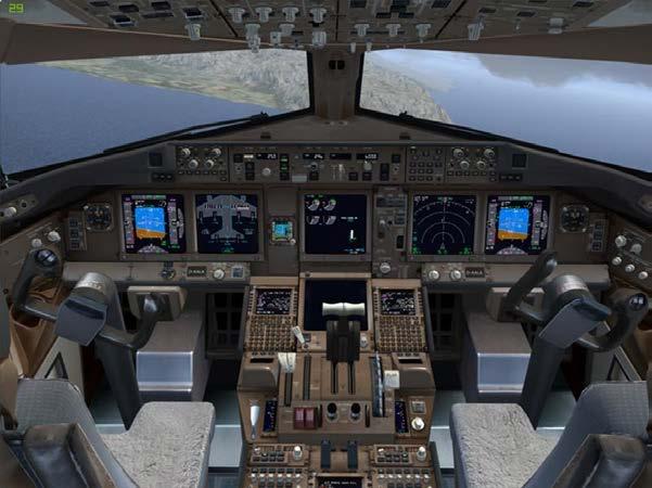
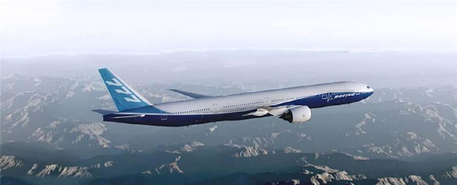
Welcome back on board the plane of the week, Senior Aviation Society! Today, David Wu manoeuvred us through the shrouded fate of the Malaysia Airlines flight MH370 – the mystery of the decade. The tragedy of how hundreds of lives were lost is yet unsolved, but what we can be certain about is that it was a deliberate act, and not some plane malfunction. Thus, let’s step back and look at the actual plane that housed all these people – the Boeing 777-300ER.
The 777 is one of Boeing’s biggest prides, sometimes even being referred to as “Boeing’s seventh wonder”. It has many features to bolster this name, from the 7s in its name to its unique fly-by wire system and the fact that it is the first aircraft to be crafted entirely using CAD technology.
Before we get into it, here are the usual...
Facts + Figures:
(which can be found through Wikipedia but it’s nice in one place )
Wingspan: 64.8 m
Engine type: GE90-115BL1
Top Speed: Mach 0.89 (950 km/h)
Length: 73.9 m
Range: 11,165 km
First flight: 24 February 2003
Cruise speed: Mach 0.84 (905 km/h)
Price: $375.5 million (£298.30 million)
Max passenger capacity: 550
Now, back to testing how far CAD can go...
Whether familiar with computer-aided-design (CAD) software or not, the awe at the feat of being able to craft an entire plane digitally remains. By using CAD, aerospace engineers at Boeing were able to accurately perform more complex calculations than ever before (think CFD testing but big). Such testing on the CAD model was obviously not used solely to assess the performance and safety of the aircraft, but it offered a valuable step to the testing stage, and reinforced wind tunnel test data.
To be able to have valid results from CAD testing, the engineers had to use parametric modelling. This is when the parts of the aircraft aren’t just drawn to resemble their physical shapes – they reflect their real-world behaviour and properties too. This means that each individual component (and in 777’s CAD model there was something of the scale of 3 million of these) must have the correct weight, material characteristics and tensile strength. Accuracy is something that cannot be compromised in an aircraft – one can only imagine the patience it took to maintain this.
Unfortunately, crafting something of this scale can’t be done on good ol’ Autodesk Inventor: the Boeing aerospace engineers has special CAD/CAM packages that they used. These include
Unfortunately, crafting something of this scale can’t be done on good ol’ Autodesk Inventor: the Boeing aerospace engineers has special CAD/CAM packages that they used. These include CATIA from Dassault Systèmes, CADDS and Pro/Engineer from Parametric Technology Corporation, and NX from Siemens Digital Industries, among others. The Boeing 777 was developed using the CATIA package.
Another nifty thing about designing your entire aircraft on CAD is the possibility of using additive manufacturing in prototypes. Here’s a helpful link that goes through this in more detail for the 777: https://www.cadcrowd.com/blog/how-the-aerospace-industry-is-using-cad-design-services-drafting-modeling-and-prototyping/#:~:text=By%20then%2C%20Boeing%20 had%20already,more%20accurately%20than%20ever%20before
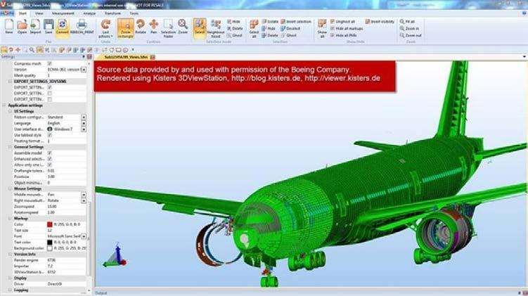
(Kisters3DViewStation loading 777 CAD model, with more than 350 million polygons and more than a million objects)
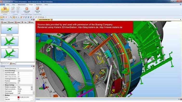
(A closer look at the turbine of the 777)
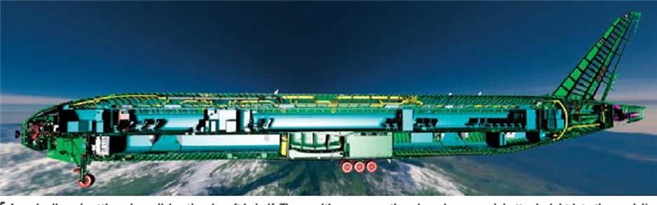
(And a very impressive cross section of the entire model)
CAD isn’t all the 777 is famous for though, it’s renowned for being a....
‘Pilot-friendly’ aircraft: FBW and advanced cockpit design
Fly-by-wire (FBW) is a control system that replaces the usual manual flight controls of an aircraft with an electronic interface – the way that I thought of it, it was the ‘automatic car’ of aircrafts. First introduced in 1987 through the Airbus A320, it was then developed by Boeing in the Boeing 777. Nowadays, most commercial jetliners have some iteration of this system.
My understanding of such advanced systems is limited, but here’s an excellent abstract on the whole system by a P.180 Captain who knows what he’s talking about: https://www.linkedin. com/pulse/analysis-boeing-777-fly-by-wire-system-jaime-beneyto-g%C3%B3mez-de-barreda/.
Regardless of whether I fully understand it or not, I can certainly appreciate how cool the cockpit looks:
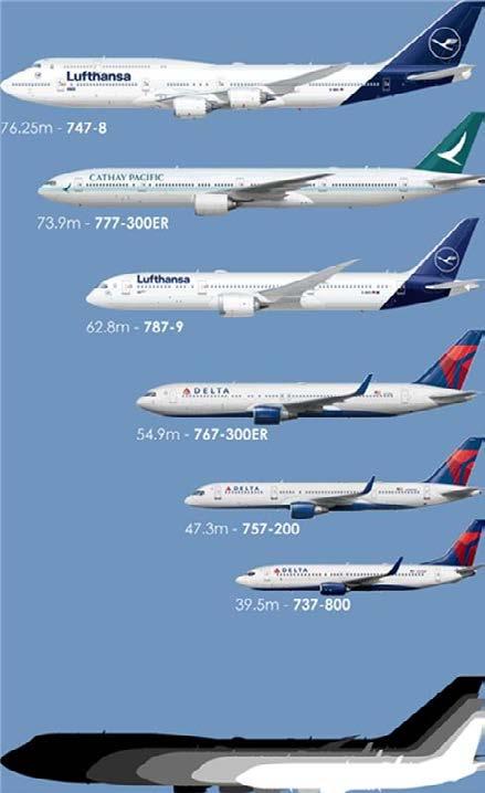
As per usual, some pictures for identification of the plane, and size comparisons with some aircraft we may have flown by before. Keep your eye on the sky for these massive aeroplanes…
Anwesha Ghosh
After long last, welcome back on board the plane of the week, Senior Aviation Society! We hope you have had a restful break and are ready to cruise through the clouds once more – this time, aboard Lockheed Martin’s sneaky tanker aircraft.
The reason why the MC-130J caught my eye this week was the announcement that the US Special Operations Command had dropped plans to develop an ‘amphibious float-equipped version’ of it. Why? The usual – budget constraints and cost effectiveness. Regardless, the MC-130J has some impressive features of its own and even if the idea was not be able to be made reality, the concept is still pretty cool.
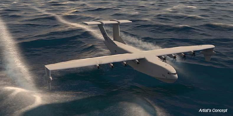
Before we fly off, let’s review the program behind the potential development of the MC-130J: the ‘Liberty Lifter’ is a US Military Defence Advances Research Projects Agency (DARPA) project launched in mid-2022 to develop a low-cost sea plane that uses ground-effect to travel long distances. If you’re unfamiliar with ‘ground effect’, Ewan Butterworth mentioned it a while back in AV 2003 for the ‘monster hovercraft’ A-90. I’ve quoted his explanation below, because I don’t think I could explain it better:
“Ground effect in aviation is a phenomenon which occurs when an aircraft and its wing are flying closely above a smooth, flat surface. In essence, because the wing is so close to the ground, air flowing beneath it is compressed between the floor and the wing, increasing the static pressure below the wing to an even greater amount than the wing will already have been doing. This results in an enhanced lift effect (that’s not an actual term, just sort of summarises it well), and means the wing becomes very good as producing lift. If you’d like to read more, here’s a link to a good paper https://apps.dtic.mil/sti/ tr/pdf/ADA361836.pdf (head to page 5).”
A conceptual photo of the Liberty Lifter is displayed below, and you’ll find it looks quite similar to the MC-130J:
Wingspan: 40m
Engine type: Rolls-Royce AE 2100 (turboprop engines)
Thrust: 4,591 shaft horsepower (3424 kW)
Top Speed: Mach 0.59 (670 km/h) at 22,000 feet
Length: 30m
Range: 3,334km
First flight: 5 April 1996
Cruise speed: 643 km/h
Price: $114.2 million (£89.69 million)
Max takeoff weight: 74390 kg
Crew: Two pilots, one Combat Systems Officer (officers), and two Loadmasters (enlisted)
All the facts are here: https://www.af.mil/About-Us/Fact-Sheets/Display/Article/104510/ mc-130j-commando-ii/
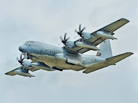
The MC-130J is an iteration of the older MC-130 family, optimized to be a ‘stealthy replacement’ for the MC-130Es and MC-130Ps. One of the factors that helped the MC-130J maximise both its power and stealth were its engines – turboprop engines.
Turboprop engines are essentially variants of the jet engine that have been optimized to drive a propeller. At the lower speeds the MC-130J travels at, its turboprops ensure that it is far more fuel efficient and require less runway for takeoff and landing, also allowing increased versatility. Due to these cost and performance advantages, turboprops are the general choice of engine for commuter aircraft. Since MC-130J’s primary functions are air refuelling, infiltration and exfiltration, the turboprop engines serve their purpose perfectly.
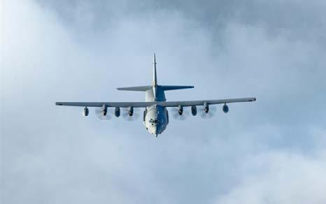
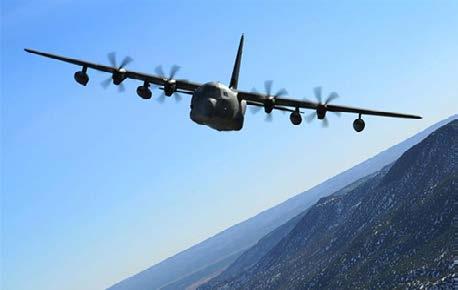
You can identify the four turboprops on the MC-130J on the wings, they give the plane its distinctive sillhouette:
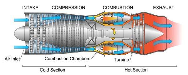
The main distinction between turboprops and their turbojet/fan counterparts is how the air flows through them. In turbojet/fans, the air flows straight through into the compressor, and then the combustion chamber where the hot, high-pressured air is mixed with the fuel and ignited. It then exits out through the exhaust via the turbine to reduce its pressure.
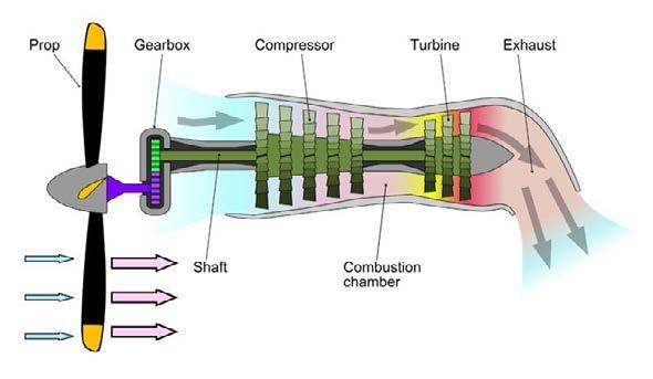
In turboprop engines, the air is redirected to the back of the engine, and the same processes as the turbofan engines occur. This time though, they’re facing the other way, so the exhaust fumes exit via the front of engine. Despite there being no practical use for these exhaust fumes, they can actually generate thrust, though it’s only a small percentage of the total thrust generated by the aircraft.
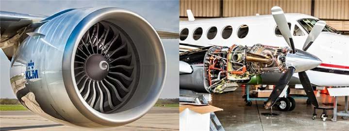
You can quite easily visually distinguish between the two engine types, by looking at the sizes of the propellers and how exposed they are (below, left is turbofan, right is turboprop).
This website walks you through how turboprops work in amazing detail: https://www.boldmethod.com/learn-to-fly/systems/this-is-how-a-turboprop-engine-works-flow-operation/
And if you want to learn more about the specific turboprops used by the MC-130J, here’s Rolls-Royce’s specifications for it: https://www.rolls-royce.com/products-and-services/defence/aerospace/transport-tanker-patrol-and-tactical/ae-2100.aspx#/
And a quick cruise through the other design features:
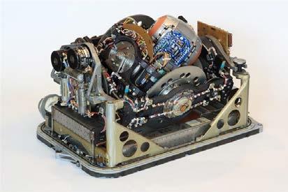
Cockpit and avionics: an advanced flight station equipped with fully integrated digital avionics and includes head-up and multifunctional colour liquid crystal displays for flight control and navigation. Also has a CSO (combat systems operator), and navigation systems including dual global positioning systems and inertial navigation system (a navigation technique where measurements provided by accelerometers and gyroscopes are used to track the position and orientation of an object relative to a known starting point, orientation and velocity; a lot of words... here’s a nifty picture as well:)
Cargo and refuelling systems: The MC-130J is equipped with an advanced cargo-handling system and the onboard universal air refuelling receptacle slipway installation (UARRSI) allows it to receive fuel in-flight from boom-equipped tanker aircraft such as the KC-135 and KC-10.
Refuelling pods enable the aircraft to perform in-flight refuelling of tactical aircraft and helicopters, as well as forward-area ground refuelling.
Though it’s stealthy, we’ve got pictures!
If you ever happen to look up and see one of these, you’re probably not supposed to have… so here’s some pictures so you know what you’re looking for.
Anwesha
Ghosh
After long last, Aviation Society has returned, and with it, your planes of the week, so get on board! Ewan flew through various types of engines today, ultimately focusing on the futuristic scramjet and the principles behind it, namely, scramjet intake design. As Ewan mentioned today, scramjets are incredibly difficult to get right, let alone apply to a wider design, so it’s no surprise that both the first and second successful scramjet flights of a scramjet powered airplane at hypersonic speeds were claimed by NASA with the X-43A.
As the name suggests, the X-43A was the first experimental aircraft of the family of X-43 variants, part of NASA’s Hyper-X program. It took NASA two failed tests of the X-43A before they finally managed to fly the at Mach 9.8 for about 10-12 seconds, though referring to it as ‘flying’ may be disputable due how the X-43 was released. Ewan went over how planes are accelerated to hypersonic speeds briefly in his talk, and the launch and release of the X-43 is the perfect example. It was ‘stacked’ with a Pegasus rocket, and released from a Boeing B-52 Stratofortress bomber, shown below:
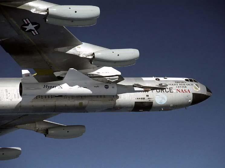
The Pegasus rocket accelerated the X-43A to Mach 10, with the X-43A splitting away at Mach 9.8 and its engine starting only at Mach 9.65. It flew with its engine for 10-12 seconds, and then glided down to the Pacific Ocean. Due to how short the flight time was, some may argue that the X-43A is essentially just a missile that lacked ability to sustain flight.
Each version of the X-43 was single use, and due to the various failed missions for a single variant, it cost absurd amounts to continue. Thus, by the X-43C the Hyper-X mission was suspended.
Thankfully though, your plane of the week today is decidedly not the X-43A, despite its relevance. Two years after the suspension of the X-43 variants in 2004, the USAF announced that the Air force Research Laboratory (AFRL) announced the design of the Boeing X-51.
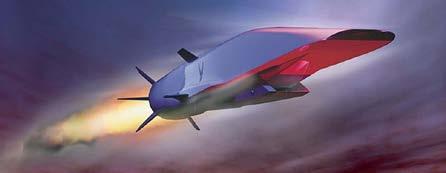
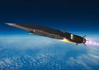
The Boeing X-51 ‘Waverider’ is unmanned (so we don’t have to pull a Tom Cruise), and is used for research into scramjet performance in hypersonic flight.
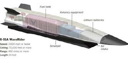
Let’s take a closer look at its specifications....
Facts and Figures:
Crew: None
Length: 25 ft 0 in (7.62 m)
Empty weight: 4,000 lb (1,814 kg)
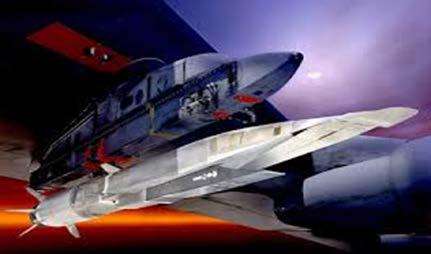
Powerplant: 1 × MGM-140 ATACMS rocket booster, 1 × Pratt & Whitney Rocketdyne SJY61 scramjet
Maximum speed: 3,900 mph (6,200 km/h, 3,400 kn)
Maximum speed: Mach 5.1
Range: 460 mi (740 km, 400 nmi)
Service ceiling: 70,000 ft (21,300 m) (which is essentially just climb, makes me think of TG:Maverick again...)
All of these can be found in greater detail in the Air Force factsheet: https://www.af.mil/ About-Us/Fact-Sheets/Display/Article/104467/x-51a-waverider/
Similar to the X-43A, the X-51 is strapped to the Boeing B-52 Stratofortress in flight demonstrations, where it is lifted to an altitude of 15km, and then released over the Pacific Ocean. The MGM-140 ATACMS solid rocket booster (the same type of stuff the Space Shuttle was strapped to!) propels the X-51 to around Mach 4.5. Once the booster has done its job, burning wholly through the solid rocket fuel stored inside of it, it falls away, and the real cool stuff starts...
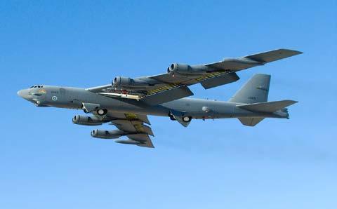
From left to right: the full B-52, X-52, MGM-140 stack, and a closeup of them under the wing of the B-52.
I don’t need to describe how a scramjet works, because Ewan thankfully covered that in today’s talk! A little summary (and gross simplification) of how the SJY61 scramjet works is displayed in the diagram below from NASA:
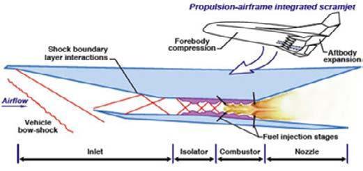
The thing with scramjet powered vehicles, is that because the inlet is so long the scramjet is an inherent part of the overall design and basically means the entire aircraft is one massive engine. However, what sets the X-51 apart is what garnered it its name ‘Waverider’ - its revolutionary propulsion, that utilises shockwaves in order to increase lift...
Compression lift is basically a way to manipulate the shock waves that make supersonic flight so difficult into a way to propel the aircraft further, for longer. It is a result of the increase in surface pressure on the underside of a hypersonic vehicle due to the thin shock layer that forms on the underside. By matching the leading edge of the wing to the shockwave formed off the forebody of the aircraft, we can manipulate the increased surface pressure in order to provide more thrust and lift.
The diagram below shows how the shape of wave riders are adapted for this purpose:
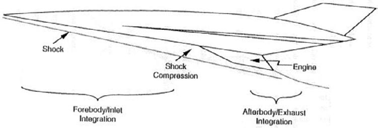
The manipulation of shockwaves is a similar concept to how scramjets are powered without any moving parts, however, the two are separated by their function. Scramjets are how the aircraft accelerates, and focus more on the ‘thrust’, whereas wave riding with compression lift is more of a method to keep the aircraft aloft at hypersonic speeds for longer.
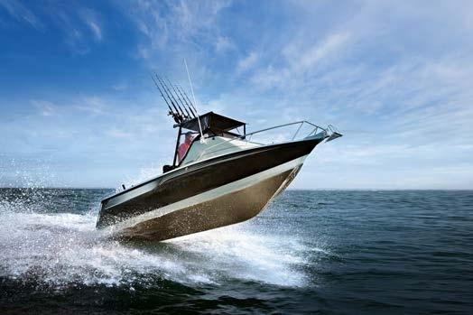
Though the concept seems a bit alien (as most things hypersonic are), compression lift will be well known to you if you enjoy sailing. When boats are ‘planing’, they are riding on top of the water rather than going through it. This occurs when they reach a speed at which the hydrodynamic forces produce enough lift for the boat to rise up and skim across the water’s surface, both increasing speed and maneuverability whilst reducing drag. It’s why when boats go fast, the hull lifts up a bit:
So, the wave riding can be taken quite literally, I guess. Air is more complicated though, and the aerodynamic wake that needs to be generated for thus to occur only happens at supersonic speeds, and is highly angled, hence the need for shape optimisation.
To sum that all up, here’s some nice pictures for us to see the product of one of the biggest collabs of all time: the USA Air Force, DARPA, NASA, Boeing and Pratt & Whitney, managed by the AFRL (The US Air Force Research Laboratory).
It’s highly unlikely we’ll ever see it in real life, but we can admire it from here...

A collection of articles on everything aviation, written by our members.
Though the talk this week (and next week) was very unfortunately cancelled, I have managed to put together the information I would’ve been bestowing upon you had we not been unavailable.
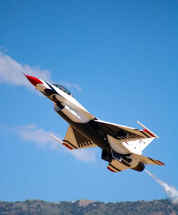
In-flight turbulence is obviously topical, with the echo of what happened on Singapore Airlines Flight 321 on May the 21st still bouncing about, but I feel that it would be very interesting (if not very useful in preventing it…) to learn about what exactly clear air turbulence is:
For anyone who has flown anywhere, one would be very lucky to have never experienced inflight turbulence before, even in its mildest effects, because turbulence comes primarily as a result of the movement of air (in most cases wind) hitting and exerting forces on an aircraft, or dramatic (and I mean very sudden) changes in air pressure that may knock it out of its original alignment. Naturally, to fully understand that you can think of the very basics of how an aircraft flies – the wings create lift through manipulation of the air they are travelling through. If this air is suddenly dramatically impacted by something like a gust of wind, it can impact the amount of lift produced by the wings and cause the aircraft to be deflected along its vertical axis of movement, or deflected sideways if the wind comes from the side. Simples!
Now, this obviously can cause forces on the occupants of the aircraft as it is nudged about, which is what we feel when the aircraft experiences turbulence.
Because wind contributes to turbulent air, we will look at what creates the wind. Most commonly, this will be weather – formation of clouds like a cumulonimbus (BIG cloud) or storms, and this is the turbulence we can see and predict. Pilots will be able to see this weather on their weather radars, if they can’t see it out of their window (which they should be able to) or if they haven’t been notified by air traffic control (ATC) about the existence of the weather which they may encounter:
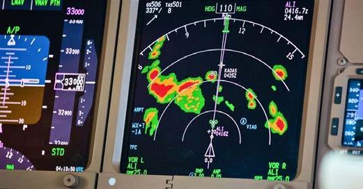
(the patches of green, orange and red display the varying severities of the weather ahead on the weather radar)
Obviously, the pilots can then ask the ATC if they can be directed around the weather if it’s very severe, and, apart from in the most critical cases, this will be approved. Naturally, if it’s just a small cloud the assumption is that there is minimal effect on the aircraft, and thus little worry is spent on flying through the small clouds (if you ever descend/ascend through clouds in a flight, you’ll most likely experience small amounts of turbulence caused by the dramatic pressure changes within the cloud). It is generally only the most serious of weather which demands avoidance:
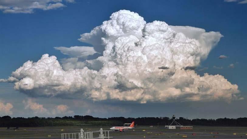
(A typical cumulonimbus cloud resides in the sky behind Gatwick Airport. These are clouds pilots should make a concerted effort to avoid, such is their potential to cause severe turbulence)
Aircraft can also encounter turbulent movements of air in scenarios like:
1. Mountain waves: why you’ll find no aircraft over the Himalayas - https://en.wikipedia.org/wiki/Lee_wave
2. Thermals: https://wiki.ivao.aero/en/home/training/documentation/Turbulence (under convective turbulence)
3. Wake Turbulence: https://en.wikipedia.org/wiki/Wake_turbulence
All of these are central to how flight paths and plans are structured, as well as in key principles of safe flight practiced in aviation, so I recommend you Google all of them for your own enrichment.
However, aircraft like SQ321 can also come across what is known as clear air turbulence. This turbulence is essentially “unavoidable” because it is almost impossible to predict, at the speeds aircraft are travelling at, when and where the aircraft might meet clear air turbulence.
It occurs primarily between 22,000 and 39,000ft, which is where most airliners will take their cruising altitude, and as a result you are most likely to experience clear air turbulence in the cruise.
The turbulent air is formed at the point where bodies of air moving at widely different speeds meet, and the shear caused by the “friction” between the two bodies. The reason it is so hard to detect clear air turbulence is because, as suggested by the name, is consists of entirely “clear” air, so is almost impossible to see with the naked eye or detect by radar. Various methods can be implemented, but these can take a while to find the pockets of turbulence, so in most part predictions are made based on the prevalence of different factors that can cause clear air turbulence to warn pilots. Mountain waves and thermals, listed earlier, are also forms of clear air turbulence, though these can be predicted with more ease than with the cause most recently described, which occurs most frequently near jet streams.
We can actually have a look at Windy.com (it’s SUCH a cool tool) to see this:
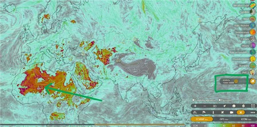
(at 5000ft, you can see the rising thermals from the Sahara Desert meaning a prediction of very high amounts of clear air turbulence)
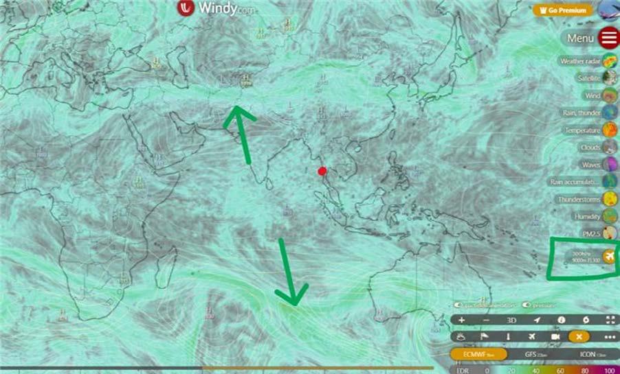
(at 30 000ft, you can see predictions following the path of jet streams)
As you can also see from the latter picture, I marked the spot SQ321 experienced the clear air turbulence, above the Irrawaddy Basin between Thailand and Myanmar. It seems from here that there is little clear air turbulence predicted, which is contradictory to what SQ321 went through, but it further emphasises the point that clear air turbulence is so hard to accurately predict, which is why it can be so dangerous to aircraft. My parents in their days working in South-East Asia experienced flying between Thailand, Myanmar and Bangladesh so frequently, and they always mention the fact that the region is turbulent, owing to the huge weather systems which can develop in the countries.
Clear air turbulence can range hugely in intensity, going from a level barely noticeable to something SQ321 experienced, and likely even further. Indeed, there are other famous cases of aircraft suffering from severe clear air turbulence, which can be found through this link https:// en.wikipedia.org/wiki/Clear-air_turbulence#Effects_on_aircraft.
I do hope that’s given a short taster into what turbulence is. There are various models and theory on turbulence, which you can find through the Wikipedia article, or through your own research, and a very good video on turbulent flow (but not the affect on aircraft) by Veritasium, if you haven’t watched it yet! https://www.youtube.com/watch?v=5zI9sG3pjVU. .
Ewan Butterworth
The skies are clear and the sun shines as Senior Aviation Society cruises along. We haven’t landed just yet, but here’s what would’ve been this week’s flight path...
I’ll be talking about a group of materials that are allowing engineers to make aeroplanes lighter and more sustainable. There’ll be quite a bit of chemistry, but one of the joys of aviation is how it’s the triple point of all the sciences and maths! So, buckle up, and let’s get started!
High entropy alloys are, as the name suggests, a bit chaotic. We first must understand the structure of normal alloys to understand these odd materials, though. I’m sure you all know what alloys are: a composite material that contains a primary metal, and a small amount of another. The inclusion of the other metal disrupts the even layers of the primary metal and makes them harder to slide over each other, and hence the metals can withstand greater forces without deformation. You’ll most definitely be familiar with the following diagram:
This diagram is an alright visualisation in 2D, but in reality, the alloys have 3D crystalline structures like the following:
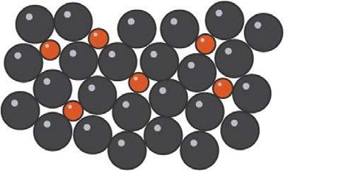
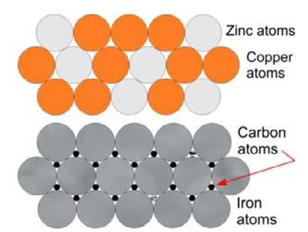
As you can see, depending on the different molecules used, the alloys arrange themselves in a different crystalline structure to accommodate the relative sizes of each of the atoms. As a result, an alloy with metals of similarly sized atoms will have different packing to that of metals with differently sized atoms. The first is known as solid solution alloys (a good example would be brass with Zn and Cu), and the second is known as interstitial alloys (which applies to the Fe and C in steel). The two structures are displayed to the right:
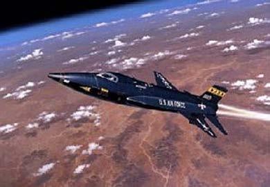
And a picture of the X-15 out of this world, quite literally:
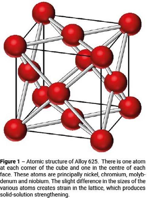
Now, what does this all have to do with aviation? Alloys have greatly improved mechanical and physical properties compared to pure metals, and allow us to test the boundaries of what we thought possible. If we go back to the Wright Brothers, they switched from their initially wooden frame to using aluminium alloys for the airframe, which was both lighter and able to withstand higher pressure loading. Nowadays, we have exciting alloys like Inconel 625, termed a ‘nickel based super alloy that possesses high strength properties and resistance to elevated temperatures’. It is often used in hypersonic aircraft due to this! Another version of Inconel – Inconel X – was used to coat the hypersonic aircraft X-15 in order to withstand the effects of aerodynamic heating at the crazy speeds it went at!
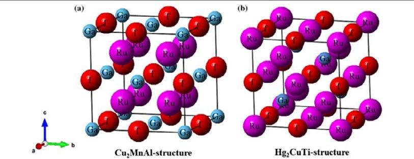
The crystalline structure of Inconel 625 is displayed to the left.
But wait! Alloys may have been cool at the time the X-15 was made (1958), but we have the newer and better subgroup of high entropy alloys waiting to be used. Now we’ve seen the crystalline structures of normal alloys, let’s expand that to high entropy alloys!
As you’ve seen, conventional alloys have a relatively regular crystalline structure. High entropy alloys contain five or more elements in roughly equal amounts, which results in high configurational entropy (which essentially means more disorder because of the many different types of atoms). Because of this, HEAs are normally composed of elements with different crystalline structures, and end up looking something like this:
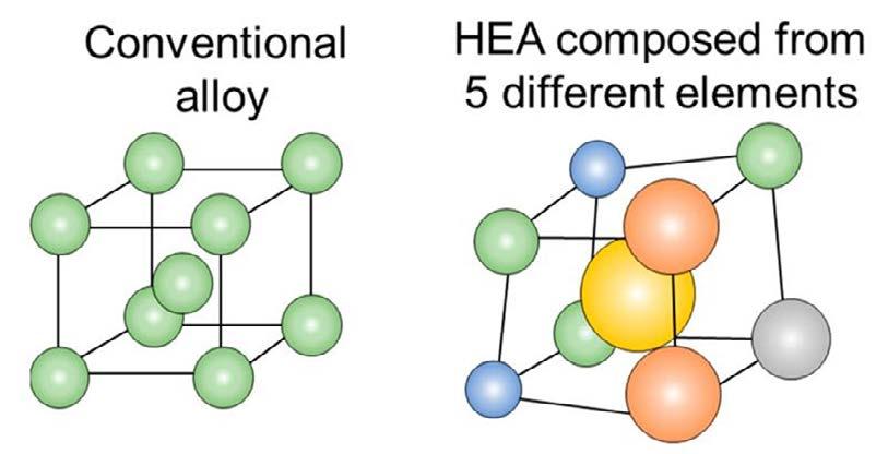
Contrary to belief, this weird shape actually results in HEAs having higher strength, hardness, wear resistance, thermal stability and corrosion resistance compared to their conventional counterparts.
In order to understand why this is the case, we need to take an even closer look at crystal lattices, namely ‘dislocations’. Due to natural variation, crystal lattices have points at which they are distorted due to an additional plane of atoms sliding between the regular structure:
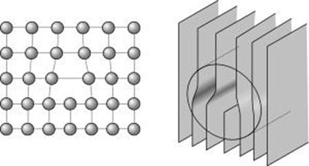
When a shear force is applied along the crystal lattices, the dislocation shifts, until it reaches a grain boundary, as displayed on the next page.
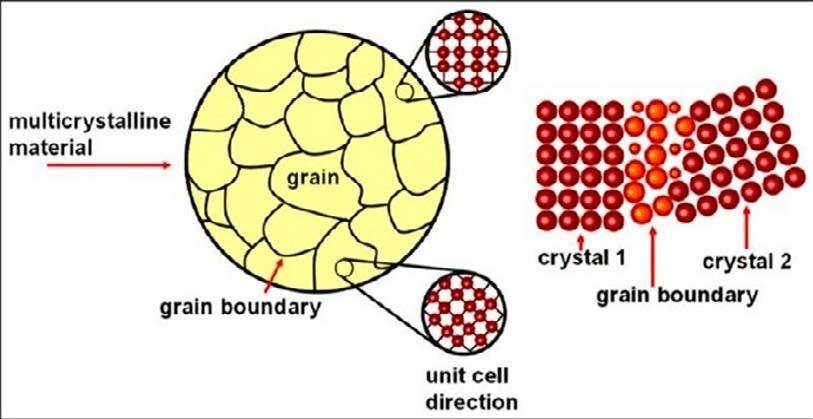
Due to the irregular structure of the HEA crystal unit cells, they have more grains. This means that when a shear force is applied to them, the dislocations have less of a distance to shift before they hit a grain boundary, and thus the metal does not deform.
Due to their unique combination of mechanical, thermal and physical properties, HEAs have various applications in aviation. One example is that HEAs may be used for high-temperature applications, such as in jet engines and hypersonic vehicles – so perhaps the X-15 could’ve lasted even longer if it had been coated with a HEA! The usage of HEAs in jet engines means that fuels can be combusted at higher temperatures, and thus complete combustion can occur, which means the fuel has a greater energy content.
Unfortunately, as with every emerging piece of technology, we’re not quite there yet… HEAs are notoriously difficult to synthesize at scale whilst keeping costs low, so it isn’t really feasible to use them in aircraft just yet. Their chaos lends itself to helpful properties, but it also means that we lack a clear understanding of the relationships between composition, microstructure and properties, and so can’t really predict what will happen to them in different conditions.
https://www.azonano.com/article.aspx?ArticleID=6374#:~:text=High%20entropy%20alloys%20are%20typically,thermal%20stability%2C%20and%20corrosion%20resistance <- everything you need to know about HEAs
https://wiki.dtonline.org/index.php/Crystalline_Structures <- a closer look at how metals and alloys are actually arranged
https://www.corrotherm.co.uk/blog/inconel-alloy-625-in-aerospace-engineering <- a bit more about Inconel 625 and how it’s been used in aviation!
Anwesha Ghosh
A budget airline is an airline which sacrifices amenities such as inflight entertainment and premade food to minimise operating costs. Examples of airlines that operate on this model are Southwest Airlines (which is the largest low-cost carrier), Ryanair and Indigo. Full-service airlines are airlines that differentiate themselves from their competition not on price but on providing better customer service and personalisation. Example of these airlines are Emirates, Ethihad Airlines and Air India. You may have noticed a trend that full-service airlines are owned by mega corporationssuch as Tata or bankrolled by oil money, but this is not necessarily true.
Strategies employed by budget airlines:
1) Budget airlines typically operate a single type of aircraft to simplify maintenance and training. This means that they can reduce maintenance costs by up to 30%. Therefore, airlines can streamline their inventory of spare parts and use fixed maintenance procedures. Due to using only one type of aircraft the number of spare parts required can be reduced by 25% in holding costs and can lead to faster maintenance, which is very important for budget airlines who cannot afford to have flights grounded for a large time. Training costs for pilots and crew can also be reduced by 50% when using only one type of aircraft. Due to the training programs being standardised, they need to train pilots in flying different aircraft. This method is most profoundly used by Southwest Airlines who operate a fleet mainly consisting of Boeing 737s. Finally, this leads to airlines such as EasyJet and Indigo to buy the planes in bulk therefore receiving a larger discount benefit from internal economies of scales. The economics behind it is that it improves market efficiency and by encouraging larger purchases, it reduces inventory costs for the producers. Also due to behavioural economics, consumers are more inclined to respond to bulk discounts. Ryanair is one of the best in the business and has the lowest operating costs in the industry.
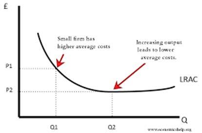
(a Long Run Average Cost or LRAC curve to display economies of scale utilised in budget airlines)
2) They also sell tickets directly to consumers via their websites therefore cutting out ‘middlemen’ and reducing their distributive costs. Approximately 75% of Southwest airlines’ bookings are from their website. This has led to these companies investing in user-friendly websites to make it more seamless and easier to organise booking experiences and due to budget airlines being an extremely competitive market, minor benefits such as this could be the difference.
3) Budget airlines typically offer low base fares and charge for extra amenities such as checked baggage or onboard meals. This therefore saves airlines money as they don’t need to hire chefs to cook premade meals when not all the users desire a premade meal. This example can be displayed in Spirit airlines in the US, allowing them to target price-sensitive travels and carve out a section for themselves in the market. However, these airlines make significant revenue from ancillary services such as priority boarding and on flight meals. Ryanair’s ancillary revenue reached 2.9 billion euros in 2020 which is 45% of their total revenue. This has been glorified all over social media with many skits being produced.
4) Budget airlines offer direct routes which reduces complexity in operations and typically fly to secondary or less congested airports. I have experienced this myself from flying to London Gatwick to Frankfurt-Hahn airport.
5) Also due to not offering first class or business class, only economy class, it allows more users to fit inside an airline. However, Ryanair has been scandalous and proposed the idea of removing toilets from flights to make room for more seats though thankfully due to large public backlash, Michael O’Leary had to reverse his proposal.
1) Full-service airlines take immense pride in their inflight services. Singapore Airlines is a prime example where Singapore Airlines is consistently ranked in the top 10 airlines in the Skytrax World airline Awards. Emirates who are known for their luxurious inflight experience. This ensures that staff provide personalised and attentive service which is essential for customer loyalty.
2) Full services airlines invest heavily into entertainment systems. Emirates ICE system is consistently rated among the best in the industry. I personally love this feature on flight as it gives users almost unlimited access to genres form Tollywood to Hollywood to live sports. Also, high-end amenities such as noise cancelling headphones and luxury toiletry kits are typical in business and first class. I believe this is essential to enhance passenger comfort and get value for your money. Qatar and Emirates are my favourite.
3) Emirates lounges are prime example of luxurious flight travel. It ranges from fine dining to spa services and business centres. Moreover, when travelling by first class or business class, you get perks such as faster check in and security and porter services.
4) These airlines also offer extensive route networks such as stop overs. This is extremely popular for flights from London to South Asia; where many users typically spend their time shopping for gold and other high-end products due to it being duty free. Emirates and other Gulf
gulf airlines are in prime position to exploit this high yield market who typically have a very high disposable income.
Which parts of the world do which types of airline have a monopoly?
1) Surprisingly in Europe and North America which have the highest GDP per capita the airline that dominates are budget airlines such as EasyJet or SpiceJet.
2) In India, Air India initially had a monopoly but over time due to poor mismanagement by the government it’s been repurchased by the Tata group which had led to an increase in its market share from its main rival Indigo. Indigo is a typical budget airline charging fees for basic amenities such as food and extra leg room. Due to India’s unprecedented growth, it’s believed that Air India will once again reach its peak.
In conclusion, budget airlines are the kings of the market in domestic travel because it’s not worth the money travelling by a more expensive airline just for 2 hours. However, the international market is dominated by full-service airlines as consumers wish to have a better customer experience over long haul flights such as to India and have the opportunity to layover in Dubai.
Here are ten links to sources that discuss comparisons between budget airlines and luxury airlines:
1. [Budget Airlines vs. Luxury Airlines: Examining the Differences](https://drafted.me/ budget-airlines-vs-luxury-airlines-examining-the-differences)
2. [Easyjet: World’s best budget airlines 2024 revealed](https://www.independent.co.uk/travel/ easyjet-best-budget-airlines-2024)
3. [The Top 5 US Airlines of 2024: The Best in First Class and VIP Luxury](https://pursuitist. com/the-top-5-us-airlines-of-2024)
4. [When to Fly on Low-Cost Carriers vs. Full-Service Airlines](https://www.nerdwallet. com/article/travel/low-cost-carriers-vs-full-service-airlines)
5. [Budget Airlines vs Full-Service Airlines](https://www.skyscanner.com/tips-and-inspiration/budget-airlines-full-service-airlines)
Rithik Rachcha
Sachin Prakash
Emirates, a UAE-based company in Dubai, is one of the biggest and most successful airlines globally. In the relatively short journey since its creation in 1985, Emirates has grown from being a small regional airline operating with just two planes, to an international airline giant flying high with over 250 planes and more than 150 destinations across six continents. This extraordinary growth and success can largely be attributed to a clever business plan. There are many factors that make Emirates’ business strategy successful; these include the strategic location of its hub, modernisation of its fleet, good customer service, innovation in marketing and strategic collaboration.
The strategic location of Emirates Airlines in Dubai is one of the main reasons for its success. At the meeting points of Europe, Asia, and Africa, Dubai makes itself a natural aviation hub. It allows Emirates to connect passengers from all over the world with ease. This is further assisted by the open-skies policy that the Emirate of Dubai has been pursuing, encouraging competition and encouraging as many international carriers as possible to operate in the airport, which has made Dubai International Airport one of the busiest in the world. By using this prime location to its advantage, Emirates managed to ensure quick and easy access to all major destinations across the world. Through this, Emirates gradually gained the position of a giant global carrier.
Another important factor in the airline’s success is Emirates’ commitment to modernising and expanding its fleet. It has been investing constantly in ordering the latest and the most efficient aircraft in order to offer enhanced comfort, more reliability, and better fuel efficiency. Emirates is known for its mega orders of Airbus A380s and Boeing 777s that make up the core of its long-haul fleet. The A380, especially, was a game-changer that brought unprecedented luxury and comfort, from private suites and shower spas in first class to spacious seating and advanced entertainment systems across all classes.
A young and technologically advanced fleet helps Emirates to provide its customers with comfortable travel, while it benefits from low maintenance and operating costs. This also would make it more sustainable as its relatively new aircraft are almost always more fuel-efficient and emit fewer emissions; their new A330neo and 787 and A350 orders help to ensure this.
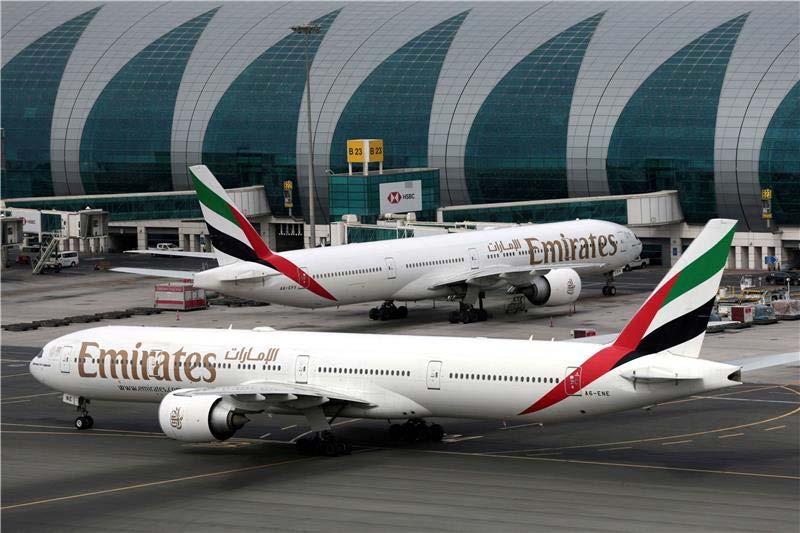
Excellent customer service is one of Emirates’ biggest USPs, and a part of the business plan itself. It is nearly always at the top of the list of consumer satisfaction surveys and has received numerous awards for the quality of service. Paying great attention to details, personalised service, and innovation in its service are the secrets to success in this area. Emirates invests heavily in the training of its cabin crew and ground staff. The airlines
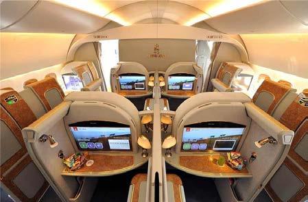
has an eye for detail to all details so that they can provide the extra services needed from the passenger: from gourmet dining options, expansive in-flight entertainment choices (specifically their I.F.E “ICE” has won numerous awards), and comfortable seating. For premium passengers who are willing to pay, Emirates goes a step further in offering exclusive lounges, chauffeur-driven transfers, and dedicated check-in counters which add to the experience of traveling.
Emirates Airlines has gained much brand presence with its innovative marketing and sponsorships; most of the airline’s marketing campaigns revolve around its luxurious product, its large route network, and customer service commitments. Emirates Airlines has also been reliable when it comes to digital marketing, with customer service support also available 24/7 worldwide.
worldwide.
Sponsorship has also been an effective way to increase Emirates’ recognition across the globe. The airline has been involved with a number of high-profile sports teams as well as sports events that include Arsenal Football Club, Real Madrid, and the Formula 1 World Championship. These kinds of sponsorships prove helpful in earning recognition for the brand as well as linking it with excellence and luxury.
Although Emirates is not a member of any of the major international airline associations (namely oneworld, STAR ALLIANCE and SkyTeam), the airline has built many strategic ties with independent airlines in order to expand its network. The majority of these are through codeshare agreements that allow Emirates to provide greater destination and better connectivity options to its network for its customers. One of the most important partnerships is with Qantas, the Australian national carrier. The two airlines are now capable of offering connectivity between Australia and Asia but also with onward connections to Europe and Middle East- a more geographically diverse market. Emirates has been able to expand its services through forming partnerships rather than alliances with other different airlines to allow the airline to continue to have success. Emirates has also been able to endure through economic downfalls. Emirates, has for a long time recorded good financial results (The airline saw an operating cash flow of AED 37.6 billion (US$ 10.3 billion) in 2023-24). This has been through factors such as passenger services, and cargo operations.
Adaptability and innovation is a reason for Emirates Airlines’ success because it has the capability of keeping its pace with changing market conditions. Whilst the rest of the Gulf countries are currently going through rapid and urgent means to diversify their economy, Emirates has not faced this issue, due to Dubai’s global reputation as a tourism hub already. The COVID-19 crisis saw Emirates rapidly focus operations on safety and hygiene through the implementation of strict health protocols, as well as increased contactless services. The power of the cargo division was activated to make up for the decline in passenger demand, thereby transporting essential goods such as face masks and medical supplies the world over. In readjusting its various strategies in such a short period of time and by building new revenue streams, Emirates was able to overcome the troublesome pandemic that was threatening its existence and come out stronger at the other end.
Sustainability is currently a large issue in the aviation industry, and Emirates has been doing its bit to focus on sustainability. The airline has done numerous things to reduce its environmental footprint and sustainably operate in the aviation industry. A modern and fuel-efficient fleet is a key investment area Emirates has focused on, because new-generation aircraft use less fuel and emit less. Furthermore, Emirates works towards minimising waste (l’ve person
-ally seen this on my many flights on Emirates, with clean, aesthetic meals which are tasty, but don’t hurt the environment), conserving resources, as well as engaging in environmentally focused conservation projects. Through things such as eco-friendly packaging, recycling programs, and energy-efficient technologies to its airplanes, airports, and ground operations, Emirates is doing its bit to play down the environmental concerns.
Overall, the successful business plan for Emirates comes from a combination of strategic vision, operational excellence, and customer services. Strategic hub location, modern fleet, superior customer service, innovative marketing, strategic partners, and strong financial management have contributed to its success.
Sachin Prakash
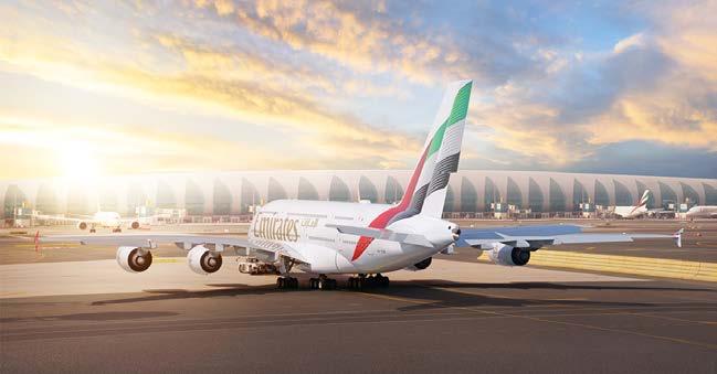
Sources:
1. History timeline: About Us: Emirates United Kingdom (no date) United Kingdom. Available at: https://www.emirates.com/uk/english/about-us/timeline/ (Accessed: 16 June 2024).
2. Cummins, N. and Hayward, J. (2023) From Desert to Riches: The History of Emirates, Simple Flying. Available at: https://simpleflying.com/emirates-airlines-history/ (Accessed: 16 June 2024).
3. Staff, S.F. and Memon, Dr.O. (2024) 5 things that make Emirates a unique airline, Simple Flying. Available at: https://simpleflying.com/5-things-that-make-emirates-a-unique-airline/#:~:text=Dubai%2 Dbased%20Emirates%20is%20one,A380%20and%20the%20Boeing%20777. (Accessed: 16 June 2024).
4. Emirates business model (2024) Wikipedia. Available at: https://en.wikipedia.org/wiki/ Emirates_business_model#:~:text=The%20so%2Dcalled%2 0%22Emirates%20business,to%20maintain%20Iow%20overhead%20costs. (Accessed: 16 June 2024)
model,attracting%20a%20diverse%20customer%20base.&text=Emirates%20mad e%20significant%20investments%20in,Airbus%20A380%20and%20Boeing%20777. (Accessed: 16 June 2024). 17. Achille, A. (2024) Middle East Carriers, how they operate a massive hub and spoke, Flights
5. Emirates (2024) Emirates Group announces 2022-23 results. Available at: https://www. emirates.com/media-centre/emirates-group-announces-2022-23-results/ (Accessed: 16 June 2024).
6. Nachman, S. (2023) Learn how Emirates Airlines continues to be best in class, Forbes. Available at: https://www.forbes.com/sites/sherrienachman/2023/09/14/learn-how-emiratesairlines-co ntinues-to-be-best-in-class/ (Accessed: 16 June 2024).
7. Dyson, R. (2023) 7 reasons to fly emirates on your next holiday: Best at travel: The edit, Best at Travel I The Edit. Available at: https://www.bestattravel. co.uk/the-ediUai rline-reviews/7 -reasons-to-fly-emirates-on-your next-holiday/ (Accessed: 16 June 2024).
8. Walker, V.M. (2022) A tale of two cabins: A review of Emirates First Class and economy from New York to Mauritius, The Points Guy. Available at: https://thepointsguy.com/reviews/ emirates-first-class-vs-economy/ (Accessed: 16 June 2024).
9. Qaed, A.A. (2023) Fly emirates: How the UAE used the airline industry to build soft power, Gulf International Forum. Available at: https://gulfif.org/fly-emirates-how-the-uae-used-the-airline-industry-to-build-soft-power/ (Accessed: 16 June 2024).
10. Stadler, C. (2023) The Sky’s the limit: What we can learn from Emirates Airlines Rise, Forbes. Available at: https://www.forbes.com/sites/christianstadler/2023/07/26/the-skys-the-limit-what-we-can learn-from-emirates-airlines-rise/ (Accessed: 16 June 2024).
11. PV, A. (2023) Decoding the success story of Emirates Airlines: Lessons for Business Leaders, Medium. Available at: https://medium.com/@Amal_PV/decoding-the-success-story-of-emirates-airlines-lessons -for-business-leaders-94258c3f3a16 (Accessed: 16 June 2024).
12. What is the secret behind Emirates Airline’s success? (no date) Quora. Available at: https://www.quora.com/What-is-the-secret-behind-Emirates-Airlines-success (Accessed: 16 June 2024).
13. The Emirates Success Story (no date) The First Group. Available at: https://www.thefirstgroup.com/en/news/the-emirates-success-story/ (Accessed: 16 June 2024).
14. Airline Hub (2024) Wikipedia. Available at: https://en.wikipedia.org/wiki/Airline_hub (Accessed: 16 June 2024).
15. Strategy, A. (1998) The benefits of hub-and-spoke networks, Aviation Strategy - The benefits of hub-and-spoke networks. Available at:https://aviationstrategy.aero/newsletter/Nov1998/7/The-benefits-of-hub-and-spoke-netw orks (Accessed: 16 June 2024).
16. S, T. (2023) Title: Ascending to the skies: How Emirates Airlines soared to market leadership, Medium. Available at: https://medium.com/@thanajayan16112004/title-ascending-to-the-skies-how-emirates-ai rlines-soared-to-market-leadership-2a5fd0452f5c#:~:text=The%20hub%2Dand%2Dspok e%20model,attracting%20a%20diverse%20customer%20 base.&text=Emirates%20mad e%20significant%20investments%20in,Airbus%20A380%20 and%20Boeing%20777. (Accessed: 16 June 2024).
17. Achille, A. (2024) Middle East Carriers, how they operate a massive hub and spoke, Flights Miles and Points. Available at: https://flightsmilesandpoints.com/avgeek-news/airlines/middle-east/how-does-the-middle -eastern-carriers-operations-model-work/ (Accessed: 16 June 2024).
18. Emirates Airlines: SWOT analysis of hub-and-spoke model: Free essay example (no date) StudyCorgi. Available at: https://studycorgi.com/emirates-airlines-swot-analysis-of-hub-and-spoke-model/ (Accessed: 16 June 2024).
Fighter jet manufacture boomed during WWII – most notably, the Hurricane and Spitfire. The era didn’t come without its share of weird and wacky planes though – this is where the Goblin entered and, rather unceremoniously after 7 flights, exited.
American bomber planes were in no short stock during WWII: the B-17, B-24, B-26, B-29, to name but a few. A main problem was a bomber’s size and under-aptness for aerial combat, however. And so, the XF-85 was first conceived as a parasite fighter. Stored inside the belly of a bomber, when under attack, the XF-85 would exit the bomber to combat enemy jets. It needed to be small, compact, manoeuvrable; most of all, it needed to be able to sustain stable flight from being dropped into the air, and re-dock with the bomber.
The XF-85 has a curious history. When first manufactured and tested in free flight, it had such significant problems re-docking to the bomber’s “trapeze” hook, that of 7 flights, only 3 re-docked successfully. The other 4 belly-landed on the dry lakebed at Muroc, California. Even though the jet’s performance wasn’t terrible (it reached Mach 0.8 (roughly 600 mph)), it proved lacklustre and inefficient compared to modern fighters at the time. Unsurprisingly, on 24/10/1949, the XF-85 program was scrapped.
One might think a plane this shape couldn’t fly – surprisingly, it had a lot going for it. It only weighed 2 tons (for reference, a modern F-16 weighs 10), and produced 13kN of thrust. A thrust/weight of 0.66 was higher than a lot of planes at the time, and in practice the XF85 flew quite stable.
So how does the design of this work? Swept back wings provided a stable flight, reducing the shock caused by airflow close to Mach 1 (supersonic). Furthermore, the wings had large endplates, to reduce induced drag from fast air above rolling below.
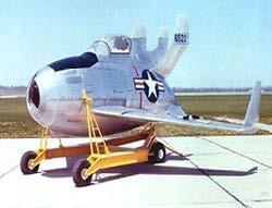
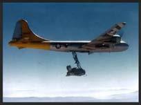
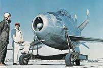
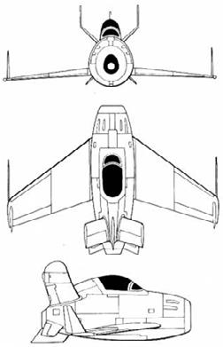
Contrary to what one might think, an eggshaped body is very aerodynamically efficient – just not commonly seen. The small nature of the plane allowed an egg design to be incorporated. To show, I did a little CFD testing on the body of the XF-85.
The egg-shaped body is aerodynamic (and this model doesn’t even account for the large engine intake on the nose). In reality, the design was fairly efficient. Where it really fell behind was manoeuvrability. Turbulence tormented the jet – the pilot Edwin Schoch couldn’t aim a gun at a fighter when the 2-tonne fighter was consistently tossed off balance by winds. But if you were wondering “how the hell does this thing even fly?”, the answer is, easier than you might think.
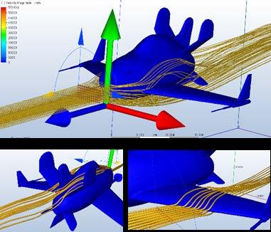
So – the McDonnell XF-85 Goblin – conceptualised as a parasite fighter in the belly of a bomber, a lightweight, compact, deployable and redockable asset to the US Air Force – realised as the smallest manned jet of all time, that flew but caused more problems than it solved, scrapped within a few years of testing.
Do parasite fighters have a future? In short, no – at least not in the conventional sense. Rather than launching manned jets from bombers, UAVs (Unmanned Aerial Vehicles) are much more efficient, for combat or reconnaissance.
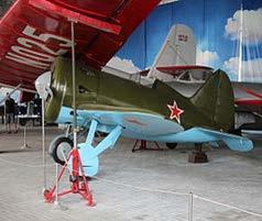
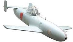
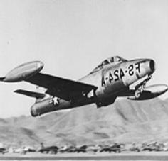
The XF-85 was in a unique category of parasites; it was developed alongside jets like the Russian Polikarpov I-16, Japanese Yokosuka MXY-7 Ohka, and American F-84 Thundercat. The Americans weren’t too good, unfortunately, at building parasites; however, both the Japanese and Russians managed to build parasites and deploy for combat, carrying out tactical attacks in Crimea and Kamikaze attacks.
Parasites were meant to help bombers – in the end they ended up slowing them down, making the bombers more susceptible to interception. It was no surprise that no parasite fighters were in development in the 1960s – 2000s. Among those designed during WW2 however, one stood out from the rest – the weird, wacky, and dysfunctional XF-85 Goblin.
Keshav Sheshadri
Sources:
“McDonnell XF-85 Goblin.” Wikipedia, Wikimedia Foundation, 30 June 2024, https://en.wikipedia.org/wiki/ McDonnell_XF-85_Goblin#Aircraft_on_display. Accessed 30 June 2024.
“Parasite Aircraft.” Wikipedia, Wikimedia Foundation, 30 June 2024, https://en.wikipedia.org/wiki/Parasite_aircraft. Accessed 30 June 2024.
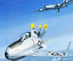
“McDonnell XF-85 Goblin.” GrabCAD, https://grabcad.com/library/mcdonnell-xf-85-goblin-1. Accessed 30 June 2024.
“Here Are Some of the Weirdest Aircraft Designs Ever.” JetsProps, https://www.jetsprops. com/prototype/here-are-some-of-the-weirdest-aircraft-designs-ever.html?utm_content=cmp-true. Accessed 30 June 2024.
Tagliaferro, Tony. “The XF-85 Goblin: The Parasite Fighter That Didn’t Work.” Defense Media Network, 8 January 2014, https://www.defensemedianetwork.com/stories/the-xf-85goblin-the-parasite-fighter-that-didnt-work/. Accessed 30 June 2024.
On the 6th of November 1957, a new era of flight was about to begin – a new, revolutionary aircraft built by the British plane manufacturer, Fairey Aviation. This was no regular plane or a regular helicopter, yet it could do Vertical Take-Off and Landing (VTOL) manoeuvres while flying internationally, carrying seventy-five people. It may look part plane, part helicopter, but in truth – it is neither.
All of that costed airlines just 25p per seat mile of travel in today’s money, or <2p per seat mile at the time, cheaper than any helicopter. Even the colossal Airbus A380 is only just half the price of this 1960s marvel to operate relative to its range and capacity, even with modern technologies, huge size, and unbeatable range. To clarify, a seat mile is a unit of price used to find the cost efficiency of a plane, the cost of operating it per person per mile it travels.
What was this helicopter-plane hybrid super-aircraft? The Fairey Rotodyne.
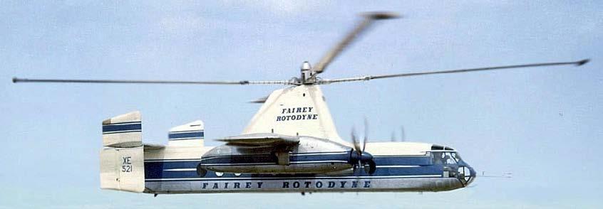
The Rotodyne was the perfect mix of these two forms of transport – a type of aircraft known as an Autogyro – a type of aircraft largely forgotten today.
An autogyro is essentially a plane with helicopter blades on top. However, these blades are not powered, so they cannot qualify as a helicopter – instead they take advantage of autorotation – the tendency of these blades to spin unpowered when the autogyro plane is moving forward. This contributes to lift. This is why a helicopter’s blades continue spinning even when power is lost, allowing it to land slowly,
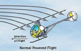
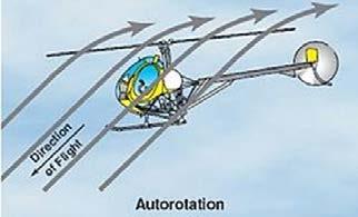
even slower than a parachute would let it. This is why Autogyros were used for many years as scout planes or to deliver mail in the 1930s – a plane could continue flying even at speeds where any wing would stall.
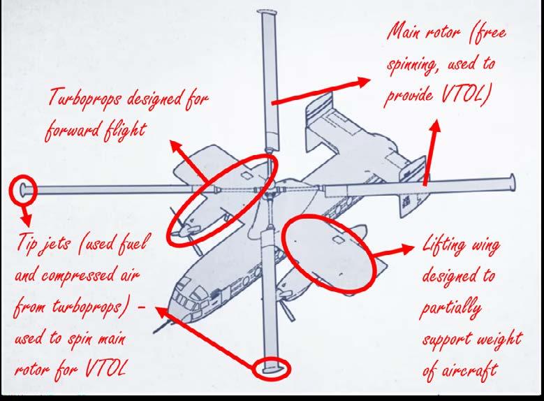
It is based on the autogyro concept but leverages parts of it to gain VTOL capabilities while remaining efficient. It had short lifting wings designed to keep it flying during forward flight (however assisted by the main rotor which will undergo autorotation, creating more lift). This forward flight is maintained by the two main turboprops.
But how does it do VTOLs? The main rotor is free-spinning and has no engine attached to it after all. This is where tip jets come in. The turboprops run during VTOL, however, they run to produce compressed air for the “tip jets” instead of providing any meaningful thrust upwards. This compressed air and some fuels are pumped into the main rotor to miniature jet engines on the tips of each blade in the rotor – allowing for it to be spun up during take-offs and landings without needing to rely on autorotation, which usually requires some amount of forward flight.
These tip jets would later become an issue.
The Rotodyne was built upon the ideas behind the much smaller, prototype testing plane FB-1 Gyrodyne. It was made to solve the biggest issue with inter-city centre travel. The traffic
of cars, and cost. Travel by car was far too slow for the businesspeople who needed to attend meetings in different cities with only a few hours to travel. The solution for many? Planes.
However, there was one (very large) issue. The airports were outside the city centre and the transport time between these airports to the city was only growing – often reaching or surpassing the flight time, which on average, was only an hour.
You may have a specific transport option on your mind – one that can land almost anywhere, even on the rooftop of the very building they may have a meeting in. You are not alone, and this resulted in an explosion of helicopter transport services.
However, helicopters lacked the range and speed to do longer trips. Even in the case that they were capable of certain journeys, the new helicopter airlines that had arisen from this demand were unable to turn a profit due to the high costs of operating a helicopter, instead relying on government subsidies that could fade away at any moment.
This meant that Rotodyne gained global interest as the solution to inter-city travel, making it receive many international orders. It helped that even the first prototype worked fully, carrying forty passengers up to seven hundred kilometres (enough for a trip between the rooftops of specific skyscrapers from London to Frankfurt) at speeds of 300km/h – while also landing on a space the size of the plane itself, vertically.
Due to the nature of Britain’s aircraft industry at the time (many, smaller manufacturers) –many companies did not have the budget to develop a new type of aircraft from scratch, and so prioritised designing for military uses as to be awarded a grant for the development of the aircraft from the government.
The Rotodyne was built on this government funding. However, there were simply too many manufacturers for the government to give individual grants to, and it was also causing other problems logistically and economically. This meant Fairey Aviation and practically every other manufacturer in the industry was forced to form multiple mergers into just a few, larger companies.
So how did the project die? In the worst way possible. A series of truly unlucky, unfortunate events.
The mergers had the Rotodyne competing with other helicopter projects trying to solve the same issue in the same company. The tip jets were simply too loud (113dB!) for use in cities, and even with the development of mufflers dropping their loudness by 85%, they were still extremely loud. And worst of all, facing economic troubles, funding for the program was suddenly pulled by the British government in 1962. All documents and the 40-passenger prototype (labelled Type-Y, the 75-passenger version to be the Type-Z) were destroyed, with only a few scale models and remnants left of the project as a whole.
Abhinav Malladi
Sources:
https://en.wikipedia.org/wiki/Gyrodyne https://en.wikipedia.org/wiki/Fairey_Rotodyne https://en.wikipedia.org/wiki/Autogyro
Abstract
Drones have been of great interest to several industries and organisations in recent years, for applications ranging from disaster rescue operations to package deliveries. In this paper, we investigate the engineering and physics principles behind quadcopter drone design/mechanics and link this to control theory, including PID control.
In a standard quadcopter drone, the forces required for all useful motion are generated from the propeller blades, which work in tandem under tight restrictions governed by control theory. The primary driver of this motion is the lift generated by the carefully-designed propeller blades. Several design parameters, including pitch, thickness, chord length along the section, skew, and camber have been considered and optimised. In industry, this is often done with fully automated studies and topology optimisations.
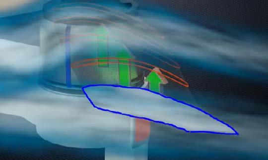
Given a sufficiently accurate computational model and topology optimisation algorithm, which may account for CFD (Computational Flow Dynamics) and FEA (Finite Element Analysis) analyses, designers can reach fairly optimal designs. The importance of these methods cannot be understated: for such lightweight devices which inevitably suffer from shorter operational times before needing to be recharged, efficient transfer of electrical power to lift forces is key. Practically, computational methods may also reduce the need for physical prototyping during iterative design, enabling manufacturers to converge on optimal designs faster and more cheaply. [2]

Figure 2: Infographic displaying some key components of the IMU
Typically, quadcopter drones are equipped with an IMU (Inertial Measurement Unit), featuring a set of accelerometers, gyroscopic sensors, magnetometers, and other measurement instruments. These are responsible for providing detailed real-time information about the drone’s position, orientation, and velocity. Accuracy is key to making well-informed control decisions, which we will discuss later in this paper. [1]
Generative design, simulation, and trade-off studies into drone frame design have shown that hollow circular sections for the drone arms provided a suitable balance between sustainability, weight, and aerodynamic performance. Materials like PLA, ASA, and ABS have been selected for their superior manufacturability and structural performance characteristics. [2]
The justification for a four-propeller drone system, despite the increased power consumption issues, stems from the principle of Newton’s third law of motion. Explicitly, for every action, there is an equal and opposite reaction of the same type. Thus, when a torque is applied on the rotor by the stator, there is also a torque acting in the opposite direction on the stator from the rotor. If you considered just one of these propellers, that would cause the drone to start spinning in the opposite direction to the propeller’s spin direction. However, the layout displayed in Fig.3, with diagonal pairs of propellers spinning in opposite directions, ensures that the torques cancel out. As long as this balance is maintained, the drone will stay in rotational equilibrium.
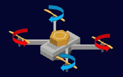
Figure 3: Torque cancellation due to diagonal pairs of propellers rotating in opposite directions.
Although torque cancellation could be achieved with a dual propeller system for a lower power consumption, this setup severely limits the flexibility of motion for the drone. Though there have been a number of fairly successful attempts at such a design [3], as we will discuss in the next section, the mechanisms for more precise movement and control are far less reliable and significantly more difficult to implement than for a standard quadcopter.
In flight, a drone should have 3 degrees of freedom to rotate, which, by standard, are referred to as roll, pitch, and yaw. Each of these rotations can be controlled by the difference between the propeller speeds on the quadcopter’s propellers.
For example, as shown in Figure 5, a roll motion may be achieved by increasing

4: Inforgraphic showing the principle axes of rotation for aircraft
the propeller rotation speed (propeller RPM) on a pair of propellers on one side. The torque cancellation effect is conserved, preventing any yaw, but a greater lift is generated on one side of the drone than the other. Modelling the drone as a single, rigid body with arms of equal length, a simple moments analysis will show that the drone will roll about its centre of mass.
Pitching motion can similarly be achieved by increasing propeller RPM on the front pair or back pair of propellers, which will result in the ‘nose’ of the drone going up or diving respectively. Note that torque is still conserved in this case: summing the clockwise and summing the anticlockwise RPMs should show that they are still equal, as long as the increase in the two propeller RPMs are equal.
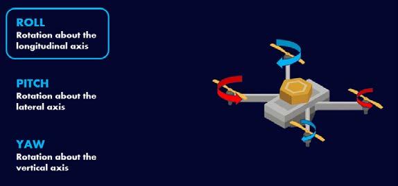
Yaw motions can be achieved by violating the torque cancellation policy we have previously adhered to for the roll and pitch rotations. Explicitly, by deliberately reducing the RPM (and thus, the torque) of both anticlockwise propellers, there will be an overall clockwise torque on the drone, enabling it to yaw, as shown in Figure 6.
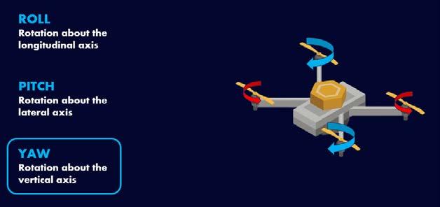
Figure 6: Reducing the anticlockwide torque will cause a resultant clockwise toeque on the drone.
These basic rotations further enable us to make our quadcopter drone move in more useful ways. Consider Figure 7, where the drone has been pitched forward slightly. Modelling the drone as a particle, we can draw a force diagram, involving the weight and propeller thrust (frictional effects such as drag have been ignored for simplicity). This force diagram demonstrates that, in order to produce a resultant force forward without any vertical forces, the vertical component of the propeller thrust must be equal and opposite to the weight of the drone. This leaves the horizontal component of thrust, accelerating the drone forwards.
The pitch angle and propeller RPMs must be carefully finetuned to achieve this smooth motion, factoring frictional effects into the calculations for a real drone. It is thus crucial that the pitch can be accurately measured using electronic levels or similar tools while the drone is in flight. Failure to do so could cause a quadcopter drone to follow unintended paths.
So far, our discussions of drone mechanics have assumed an idealised closed system to enable easy manual control of a drone through simple, pre-set tweaks to propeller RPMs. However, as is the case in much of engineering, designs built only for idealised closed systems are incompetent at dealing dealing with the chaos of real world conditions.
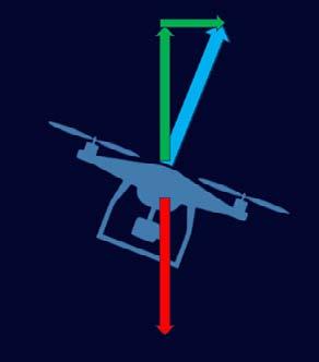
Figure 7: Force diagram fir pitched drone in flight. propeller thrust resolved into components, shown in green.
Consider the example of a gust of wind, accelerating the previously stable drone out of its 0 roll orientation. Manually correcting for these random events is possible, but certainly not feasible for a human drone operator, who will be limited by reaction time and misjudging the current conditions. Thus, the need for a level of autonomous control arises.
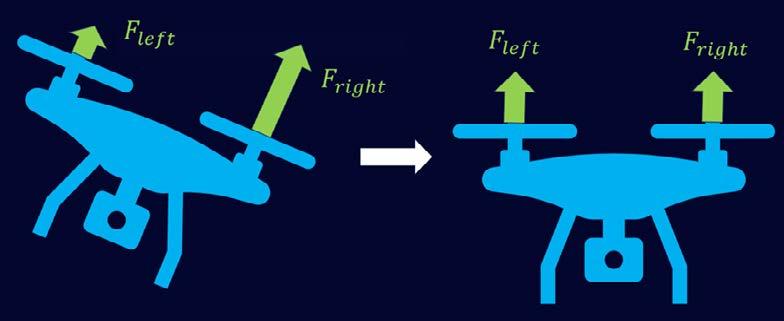
Figure 8: Infographic showing the ideal orientation restoration process.
To smoothly restore our drone back, an angular acceleration (and thus, a torque in the opposite direction to the roll) is required . Given just this condition, it would be sufficient to reach the 0 roll position, but we also require an angular velocity and angular acceleration of 0 at that point, to ensure the drone does not ‘overshoot’. The thrust forces must therefore adapt throughout the restoration process accordingly.
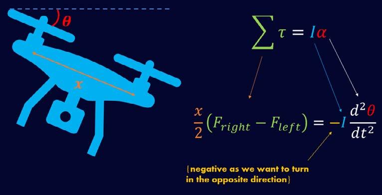
Figure 9: Formulation of the relationship between the sum of the torques and the angular acceleration.
We formulate an expression from this relationship between the sum of the torques and the angular acceleration. Modelling our drone as two thin rods crossed over with point masses on the ends for the motors, I represents the moment of inertia for our drone. For our purposes, this can be thought of as the equivalent of mass in F=ma: in other words, moment of inertia describes how difficult it is to angularly accelerate something with a torque. Given that x is the distance between the motor point masses, and is the initial roll angle:
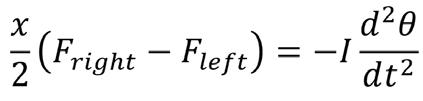
This yields a differential equation, which can be difficult or computationally expensive to solve in its current form. One approach to simplifying the process of computing a solution hinges on the Laplace transform, which is an integral transform that converts a function of a real variable (in this case, t in the time domain) to a function of a complex variable (usually notated as s, in the frequency domain). The general Laplace transform is as follows:
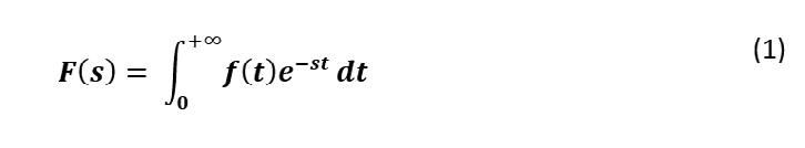
(where F(s) denotes the function in the complex variable s, and f(t) denotes the original function in the real variable t)
Applying this transform to a linear differential equation yields simple polynomial terms in s, for which a solution can be computed easily [4]. Finally, the inverse Laplace transform is applied to the solutions to convert back to the time domain. The general inverse Laplace transform is as follows:
In the context of our drone roll formulation, this will enable us to calculate the individual forces required from each propeller.
We show the steps of one concrete example below, with the following parameters:
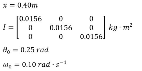


(where is the initial error angle from the horizontal, and I has been expressed as a tensor. The angle from the formulation in Figure 9 will be treated as a function of time, (t), for the main calculation. The forces and will also be treated as individual functions of time, and . . Note that either L{f(t)} or F(s) may be used to denote the Laplace transform of f(t).)
We first derive some useful Laplace transform results:
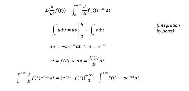
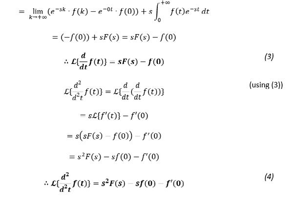
Returning to the original formulation from Figure 9 and the parameters of our concrete example, we compute the Laplace transform and substitute as follows:
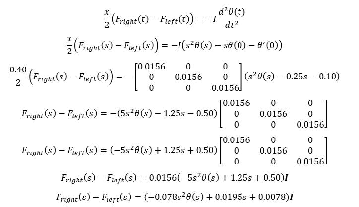
It is clear how the Laplace transform has simplified the differential equation into a polynomial in s, whose solutions may be computed and converted back into the time domain using the Inverse Laplace transform as stated in (2). We leave this step as an exercise for the reader.

The graphs in Figure 10 model the ideal restoration process. Since there is an initial positive angular velocity , the angle will increase initially, but at a decreasing rate, due to the angular acceleration applied by the propeller torques. The end result of this process should bring all 3 of these variables to a magnitude of 0.

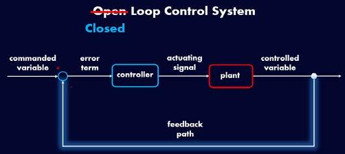
Figure 11: Infographic showing the difference between an open-loop and closed-loop control system
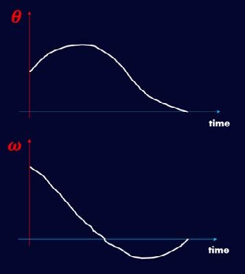
^ Figure 10: Time series graphs for the changes in error angle and angular velocity.
This mathematical formulation and process forms the basis for an open-loop control system, where the parameters are measured and then processed by the controller mathematically, before an appropriate actuating signal is generated. This signal tells the plant (the hardware carrying out the action: in this case, the propeller motors) what to do to ‘control’ the desired variable. In our drone example, this ultimately attempts to restore the roll angle and roll angular velocity to 0.
However, open-loop control systems have a number of disadvantages, tied to the fact that their outputs can only be determined by the present-state input. The open-loop control system has no method of evaluating the efficacy of its real-world actions. Any combination or even single occurrence of new external forces, unpredictable aerodynamic effects, or computational errors can throw the system into disarray entirely.
Control theory addresses this issue using a feedback path, turning this into a closed-loop control system. The purpose of a feedback path is to check the error in the desired variable throughout the process and provide feedback to the controller, which will be used to process new actuating signals.
One common method of mathematically formulating this closed-loop control system is PID control. PID stands for Proportional, Integral, Derivative – these represent 3 separate controllers, which each take an error measurement and produce an output. These outputs may
be weighted to change the behaviour of the overall controller: the process of changing these weights is known as fine-tuning. Formally, this is mathematically defined by the following:
(where u(t) represents the actuating signal output from the controller, the weights are Kp, Ki, and Kd, and e(t) represents the measurement of the error in the desired variable)
We may also apply the Laplace transform from (1) to obtain a simpler equation in s:
To discuss the individual behaviours of each of the P, I, and D controllers, we will consider the example shown in Figure 12, Figure 13, Figure 14, and Figure 15 of flying a drone to an altitude of 50m, before stabilising it there. The drone will ideally hover at exactly 50m from the ground, with negligible vertical movement after it reaches that point.
In this problem, the propeller speed value must be controlled to enable the drone to ascend smoothly until it is just hovering when it reaches 50m. Assume that a propeller speed of 100rpm will allow the drone to hover without changing altitude. This means that the final propeller speed should be 100rpm (when the altitude is 50m).
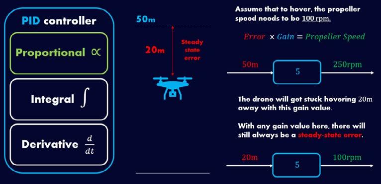
The first approach hinges on the proportional controller. It is more useful to think about the altitude as an error distance (i.e. 50m -altitude), and this lends itself to the general goal of minimising the error at all times regardless of the context of the control system at hand. The P controller multiplies the error by a pre-set ‘gain’ value to get the final propeller speed. Initially, the drone has an error distance of 50m, which gives the following calculation:
50m x 5 = 250 rpm
This leads to a positive acceleration upwards, which will decrease in magnitude as the drone reduces its error distance by flying upwards. This enables a smoother approach to the 50m altitude goal. However, repeating this process for an error distance of 20m yields the following:
20m x 5 = 100 rpm
Clearly, this setup will cause the drone to stop 20m short of the goal. This issue, known as steady-state error, will persist for all sensible choices of the gain value, making proportional control on its own insufficient for this problem.
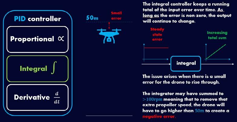
Figure 13: Integral controller keeps a running total of the error over time, but this may lead to ‘overshooting’. [5]
The integral controller keeps a running total of the input error over time. Given a non-zero error in the drone’s altitude, the value of the integrator part will continue to increase while the drone is below the 50m mark, increasing the propeller speed further. This can work in combination with the proportional controller to eliminate the issue of steady-state error.
However, if the integrator has summed to a propeller speed greater than 100rpm, the drone will deliberately overshoot the 50m mark in order to get a negative error, which will allow the propeller speed to decrease back down to 100rpm. Often, this will lead to an oscillating motion around the 50m mark, which is not ideal according to the requirements we established.

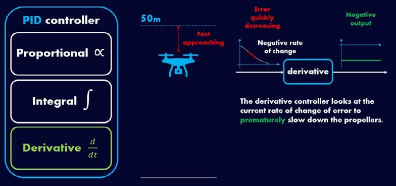
Figure 15: Derivative controller uses current rate of change of error to cause a premature decrease in propeller speed. [5]
The derivative controller produces an output based on the current rate of change of error. If the drone is quickly approaching the 50m altitude goal (i.e. decreasing its error distance rapidly), the derivative controller produces a large negative output. Counteracting the quick approach, this prematurely slows down the propellers in our example, reducing the risk of overshooting the 50m altitude goal and bringing the propeller speed smoothly to 100rpm at the desired altitude.
Balancing the behaviours of these 3 controllers carefully via the fine-tuning of controller weights allows drone engineers to create effective closed-loop control systems with relatively small computational costs.
Drone engineering is largely a balancing act between physical construction, accuracy in the electronic measuring instruments, and the manual/autonomous control principles which govern a drone’s motion. Innovations in this field, such as the penny-sized Piccolissimo drone [6], introduce new ways of thinking about these challenges and demonstrate their intersectionality when applied to engineering. By expanding this drone engineering industry to involve more innovating minds, we can further push the potential of drones to revolutionise our modern world.
Jawad Uddin
Sources:
[1] LESICS, “Drones | How do they work?,” 2021. [Online]. Available: https://www.youtube.com/watch?v=N_XneaFmOmU. [Accessed 2 July 2024].
[2] J. Bright, “Optimization of quadcopter frame using generative design and comparison with DJI F450 drone frame,” 1 January 2019. [Online]. Available: https://iopscience.iop.org/ article/10.1088/1757-899X/1012/1/012019. [Accessed 2 July 2024].
article/10.1088/1757-899X/1012/1/012019. [Accessed 2 July 2024].
[3] M. Rostami, “Aerodynamic performance of mutual interaction tandem propellers with ducted UAV,” 4 December 2020. [Online]. Available: https://www.sciencedirect.com/science/ article/abs/pii/S1270963820310816. [Accessed 2 July 2024].
[4] S. Boyd, “Table of Laplace Transforms,” [Online]. Available: https://web.stanford. edu/~boyd/ee102/laplace-table.pdf. [Accessed 4 July 2024].
[5] MATLAB, “What Is PID Control? | Understanding PID Control, Part 1,” 22 May 2018. [Online]. Available: https://www.youtube.com/watch?v=wkfEZmsQqiA. [Accessed 4 July 2024].
[6] MODLAB - UPENN, “Piccolissimo,” 27 October 2016. [Online]. Available: https:// www.modlabupenn.org/piccolissimo/. [Accessed 4 July 2024].
From aluminium frames all the way to carbon fibre reinforced polymers, the materials we use in aviation have greatly evolved from what we once started with. If you are aware of material development, you would know that with this evolution of materials comes a need for large amounts of rigorous testing. This article will dive into the specifics of materials utilised currently, the testing process and what the future of materials in aviation holds.
Why do we care so much about materials in the first place? Looking at the typical conditions faced by a commercial plane during flight, at cruising altitudes there is only 0.3 atmospheres. Additionally, temperatures get to as low as -56.5°C1. To prevent damage occurring to both the external and internal components of the plane, materials must be developed to suit this need. However, these materials must not only be corrosion resistant but also lightweight as to not affect the aircraft’s ability to generate lift and take-off in the first place. By forming composites, more commonly carbon composites, we can extract the best properties of each material to use.
There are a variety of composites to choose from to use in the aerospace industry. One of the first composite materials used was fibreglass. Fibreglass is a lightweight composite material which is composed of glass fibres which are either woven, arranged randomly or flattened. These fibres are then encased within a heated polyester resin. A catalyst is then needed to set the resin, usually being methyl ethyl ketone peroxide. It tends to have a density of 2.4 g/cm3. In comparison to the density of aluminium alloys3 which are around 2.7 g/cm3 this, despite it seeming to be a small difference, when applied to the use of the material throughout the whole aircraft can make a huge difference in terms of the weight of the overall aircraft structure and hence costs and how much fuel is required.
The interwoven matrix system of the fibres means that this material is considered to be stronger than aluminium itself. It became so popular that in 2012 Boeing made its 787 Dreamliner to be composed of more that 50% of fibreglass4. There are many advantages to this composite material- it is lightweight meaning that the heavy load that the aircraft must bear is greatly reduced from the use of this material. As well as that, in the manufacturing of this material the surface itself is inherently smooth so no additional treatment costs are incurred by the manufacturing company to achieve that look. Fibreglass itself is also quite resistant to corrosion as well as cracking which makes it suitable to be used for the aircraft externally as it can therefore withstand bending and atmospheric conditions.
Another popular composite used in aircraft structures is CFRP. CFRP, carbon fibre-reinforced plastic, essentially consists of microscopic carbon fibres which are embedded within epoxy resin. The required level of rigidity for the aircraft as well as the load-bearing properties of CFRP is achieved through the meticulous and precise fabrication process- this includes the building up of layers of carbon fibres and then curing and hardening of the resin and fibres via the use of an autoclave. The airframe of the A350 itself, as described in the Airbus website, consists of more than 70% of ‘advanced materials’ which refers to composites, modern aluminium alloys and even surprisingly titanium. Within this, the aluminium alloys consist of 20% of the aircraft and contain lithium (which is the world’s lightest metal) allowing the weight of the aircraft overall to decrease substantially from what it once was. Comparing CFRP to aluminium directly, it can perform better in terms of its strength, weight as well as resistance to corrosion which makes it a very popular material to be used in aircraft manufacturing and explains the large proportion of materials that it takes up within this one.
Whilst carbon composites and fibreglass tend to be used in the external fuselage of an aircraft, we can also look at other composites used in the avionics and electrical components internally. One example of this is the Silicon Carbide5 composite material. This material is extremely hard, being a 9 on the Mohs scale, and so it therefore in this aspect makes a desirable choice to use. Silicon carbides also exhibit the characteristics of semiconductors, and this makes it useful to be used in the PCBs found in many avionics. It has elevated temperature resistance and thermal shock durability makes it ideal for use in avionics and ensures that during use of the electronics and as it heats up it will not lower in performance- the decomposition of the material is known only to start at 2000 °C.
The process that we use for testing the temperature resistance of a material being developed as well as its response to temperature shock is through using a temperature testing chamber. Within these chambers, the ‘shock’ faced by a plane depleting in temperature as it rises in altitude is replicated via cycles of varying the temperature. Firstly, the upper and lower temperature extremes must be calculated carefully. It is then decided whether the specimen of material is tested in a single or double chamber- this depends primarily upon the rate of change of temperature required. The Faraday Test Centre located at BAE Systems Rochester have the capabilities to test products from a range of temperatures of –60 to 120 °C⁶. If a change of up to 30 °C a minute is required, then a single chamber is sufficient. If either a faster rate of change, or a larger temperature change is required then the sample can be transferred from one temperature extreme to another via a 2-zone system. The cycle of testing is then carried out, allowing the manufacturer to choose from 1A, a half-cycle, 1B, a full cycle, 1C, multiple cycles, and 1D multiple cycles (and so multiple shocks) to more extreme levels. A temperature shock itself in the aforementioned facility would be classified as a temperature change of 140 to –40 °C in 1 minute. Post-cycle the manufacturer would then observe whether any damage has occurred to the material and the iterative process of designing the material used in the component would continue thereafter.
It is essential as well that during the take-off of an aircraft that the components and materials remain intact, so to test this phenomenon we use a vibration test chamber. The process would begin upon mounting the item onto a platform which tends to sit on an oil bed. This platform is then able to vibrate with a maximum of 2.5 kilo Hertz in frequency and 66 kilo Newtons of force. Post-testing the same item will be repositioned to ensure that it is able to vibrate around all 3 axes (x, y and z) and at the end it will be ready to inspect for any damage caused. Materials used must be vibrated to high levels to ensure that they will withstand the movement that they are subjected to both during the take-off and landing procedures during flight.
From these rigorous amounts of testing, we have been able to easily make many strong, durable and long-lasting materials. However, as we look to the future sustainable practices are becoming an increasingly important. Materials can be made more sustainable in three aspects: the derivation of compounds to make the materials, the length of its lifecycle and considerations made for the end of its lifecycle.
Looking at the first aspect, we can expect the incorporation of and reusing biological waste within the structure of materials. One current large area of research is into natural fibres. This includes fibres obtained from animals and plants- from their apparent high strength and lightweight properties there is a chance that we may be seeing ‘spider silk fibre’ composites in the near future. Another area is biomass carbon fibres. This will be obtained via the creation of carbonising precursors obtained from biomass such as algae rather than the current use of oilbased precursors. One example of this is the current production of AeroFLAX7 for interior designs within an aircraft- whilst this is not specifically a material used on the exterior it shows the various applications that Natural Fibre Reinforced Plastics8 (NFRPs) have in the industry already. NFRPs in general tend to be quite lightweight, stiff and rigid as well as non-corrosive in general. These characteristics in combination with their consideration to be ‘environmentally friendly’ and renewable make them a very promising material for aerospace applications. As well as NFRPs, bio-sourced resins allowing the constituent monomers used within resin to be sourced from things like sugar cane and lignin can provide an arguably more sustainable alternative to the use of current resins within the aircraft which are oil-based.
We can also consider extending the lifetime of many materials currently in use through introducing a self-healing process to the existing materials. This would also tackle a current problem faced by many composites being that once damaged they are difficult to repair due to their complexity in nature. We can address this in one way by embedding tiny microcapsules within the resin which will contain epoxy monomers. The aim is that when the material cracks these microcapsules will then rupture. This would release the resin, filling the crack and setting within 48 hours to ensure that the crack is healed before it even has a chance to grow larger. A group of scientists currently at Bristol University claim that their self-healing materials can regain close to 80 percent of their original performance once fully healed. Another approach is through embedding a mini vascular system within the resin (to mimic the blood vessels within our body). Once a rupture occurs within the material, the epoxy resin contained and an amidoamine hardening agent will then come into contact and mix. This would then harden and another added advantage of this, when tested, was that they found repeated healing of the material could occur even if the network had been previously damaged.
Some base their opinion of how environmentally friendly a material is from its end-of-life considerations. At the moment CFRPs are recyclable, but the product it forms does not circulate back to its original form. Once the waste is crushed and undergoes pyrolysis, it then is separated into remaining as chopped CFs or further grinding into milled CFs. The chopped CF can be formed into resin pellets which can then be used for the injection moulding process, whereas the milled CF is kneaded into resin to improve its properties when used. Looking ahead we can expect developed techniques to shred the waste and extract the carbon fibres from the mat to be reused and redeveloped into new and recycled CFRPs.
With the development of newer testing facilities and further research and insights into the performance of different compounds we are bound to be given some breakthroughs in materials science. From self-healing to biologically based, research into high-performance materials is just beginning, and the possibilities are endless!
Sonali Prasad
Sources:
Gersemi Hannes (2019), Altimetry. [online] Last accessed 05/07/2024: https://www.slideserve.com/gersemi-hannes/section-03-altimetry-lesson-08-powerpoint-ppt-presentation
Trojan Fibreglass (2018), Fibreglass and Resin safety factsheet. [online] Last accessed 05/07/2024: https://trojanfibreglass.com.au/wp-content/uploads/2018/03/Fibreglass-andresin-safety-fact-sheet.pdf
Wikipedia (2024), Aluminium alloy. [online] Last accessed 05/07/2024: https://en.wikipedia.org/wiki/6061_aluminium_alloy
Sumit Singh (2022), Why the Boeing 787 and Airbus A350 are built with composite materials. [online] Last accessed 05/07/2024: https://simpleflying.com/787-a350-composite/
NASA (2017), Silicon carbide. [online] Last accessed 05/07/2024: https://technology.nasa.gov/patent/LEW-TOPS-25
BAE Systems (2015), Environmental testing. [online] Last accessed 05/07/2024: https://www.baesystems.com/en/our-company/our-businesses/electronic-systems/product-sites/faraday-test-centre/environmental
Lufthansa Technik (2018), AeroFLAX. [online] Last accessed 05/07/2024: https://www.lufthansa-technik.com/en/aeroflax
P Balakrishnan, M.J John, L. Pothen, M.S. Sreekala, S. Thomas (2016), ‘Natural fibre and polymer matrix composites and their applications in aerospace engineering’, Advanced composite materials for aerospace engineering. [online] Last accessed 05/07/2024: https://www.sciencedirect.com/science/article/abs/pii/B9780081000373000122
One of the most notable features of birds, humans have sought to emulate a wings’ use in nature to transform the way we travel. Seen as the embodiment of the “aerodynamic design” their use in the sky has not only enabled air travel but has been mimicked by the motorsport and automobile industries to squeeze that little bit more performance. In this article I will discuss how they work and how important they could become in the future world many of us have dreamed about.
What wings do depend on the function producers assign to them. With birds, wings are the sole reason they are able to fly efficiently, and this led to the wright brothers utilising their aerofoil shape in their first plane wings.
How the wing works in these cases is as follows. A force of lift is exerted when the pressure below the wing is greater than pressure above the wing. To create this the curvature of an aerofoil shape speeds up the flow above the wing compared to the flat bottom surface. This creates a lower pressure above the wing then below it due to Bernoulli’s principle. This states that an increase in the speed of a fluid occurs simultaneously with a decrease in static pressure. This is linked to the conservation energy where the sum of all forms of energy in a fluid is the same at all points

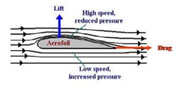
the same at all points provided no external forces act on the fluid. This requires that the sum of kinetic energy, potential energy and internal energy remains constant. An increase in the speed of airflow means an increases in kinetic energy. Therefore, potential energy and internal energy must decrease to conserve energy thus reducing the pressure above the wing. This pressure difference between the top and bottom of the wing means the aerofoil is pushed up which results in lift.
The motorsport industry uses this ideology on racing cars, but the desired force is downforce to keep the cars on the ground and provide extra grip rather than lift. To do this, designers simply flip the aerofoil horizontally so to reverse the pressure differences (high pressure on top, low pressure on the bottom) creating the desired force into the ground How motorsport wings create donwforce
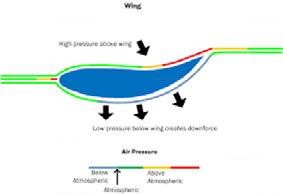
Having seen how wings create lift you might be wandering why the use the aerofoil shape in particular. Put simply, we copied nature, but why do even birds use this shape. The simple answer is drag. Drag, also known as air resistance, is a force that opposes thrust and essentially “pulls” an object back. Drag comes in two forms shear (friction) drag and pressure drag. Shear drag occurs on the surface of the wing where air rubs on the surface of it and as a result exerts a force in the opposite to the direction of motion. The thin layer of air closest to the surface of a moving object is called the boundary layer and this is where most of the friction drag occurs.
Pressure drag is caused by a pressure differential ahead and behind the object. This is mainly caused by flow separation behind the object leading to layers of air starting to swirl in the low pressure area left by this. The size of the wake (area of low pressure) created is affected by the shape of the object and how easily air can
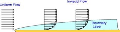
Boundary layer where Shear drag occurs
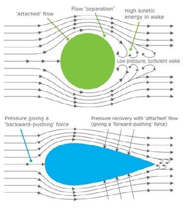
Shapes and the Wake they produce, creating Pressure Drag adhere to the objects surface. Pressure drag has the greatest effect on the total drag force.
This is why an aerofoil shape is used for wings as these produce the smallest wake and so have the lowest pressure drag compared to other shapes and hence a low drag force despite having larger shear forces. A low drag force means a greater resultant force in the direction of motion and therefore more efficient travel.
The aerofoil shape wings are not the only parts that make a wing function as they do. A common feature between plane wings and motorsport wings is the use of endplates or winglets. With the pressure differentials created by the aerofoil shape, there is a tendency for air to “spill” over from high pressure regions to low pressure regions to balance this difference. This movement of air creates a vortex which is swirling air often seen behind the wing. This causes greater drag and so less efficient travel. These are displayed bottom left.
The solution to this is the use of endplates (second to bottom right) /winglets (bottom right).
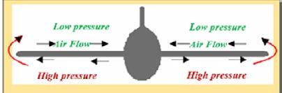
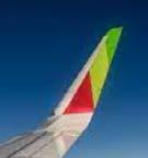
These prevent high pressure air moving to lower pressure air on the other side of the wing which leads to smaller vortices and so less drag.
Wing flaps and slats are another feature only found on planes. They are moveable parts which change the shape of the aerofoil in order to create more lift during take-off or more drag during landing. They are retracted after take-off to reduce drag while more lift is no longer needed.
Slats are found at the front of the wing and flaps at the rear.
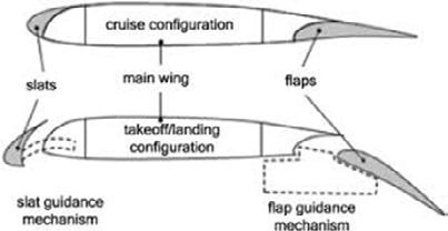
How Slats and Flaps Change the Shape of the Wing
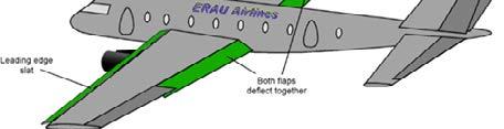
of Slats and Flaps
Wings have completely changed our perspective on air travel, but their use may not stop here. Flying cars tend to be a common feature in many people’s utopia. Wings would be set to have a major role in ensuring flying cars are safe but also economically efficient. Plane wings could also be set to change with the composite materials opening up avenues for morphing wings made of single parts. Whether these work or not is another question but one thing for sure is that wings could still see their importance rise.
Barret Marboh
Prehistoric humankind is thought to have been the original dreamer of the capability of flight – they only had to glance upward and envy the soaring birds up above, manoeuvring in any direction without any obstacle. Indeed, historical attempts at lifting humans into the air have the common feature of copying birds, like the “ornithopter” craft, made famous by the works of Leonardo Da Vinci on the concept, inspired by the flapping of birds’ wings.
‘Bio-inspired flight’ as a result captures the essence of all aviation as it is today and, to be elaborated soon, underlines a small yet key part of research and development in the aviation industry for the future.
As a Year 12 student looking to go into further education, I naturally am completing the classic round of university open days, and my visit to the University of Bristol and the Flight Lab in the engineering department brought the idea of Bio-Inspired Flight truly into my interests. Even though prior to the day I had done some cursory investigation into the intriguing way in which owls have the quietest flight of all birds, scanning over the research and models displayed in the department made me appreciate to a greater extent the amount of innovative (if not, copying) potential with regards to implementing features found in birds into current aircraft design in order to enhance performance in some way or another.
As a result, I am using this article just to write down an example of such natural design, to explain and potentially advertise this area of engineering, because it exists as an entirely viable and likely solution of the future, and as a matter of fact the recent past as well, not only within the aviation industry, but in all fields of engineering.
As aforementioned, I’ve been meaning to do some more thorough research into how owls remain so silent in flight. It is one of the key features to its success as a nocturnal predator, where acoustic stealth is essential in the remaining hidden in the quiet of the night from its prey. There is an incredibly impressive clip from the episode “Super Powered Owls” from Natural World, a programme run by BBC Earth, comparing the noise produced in flight by a pigeon, a peregrine falcon, and a barn owl (BBC Earth, 2016), where the owl is entirely silent in flight – at max volume with headphones on, I could only hear the fluttering at the end of its flight as it lands, far too late for potential prey trying to escape the talons of the owl.
This virtually noiseless flight is fascinating, and the principles behind the components of an owl’s flight that enable this are hugely valuable for future leveraging in the aviation technology of the future. Take, for example, the fines airlines can receive if they breach the noise limit during operations at Heathrow Airport, and for good reason given that the airport is surrounded by residential area – you’d think that both residents and airlines would greatly appreciate a technological advancement in noise reduction somehow.
To understand how an owl remains so quiet in flight, one must first accept the idea of how sound is produced, through vibrations in the air that form acoustic waves. Thus, the adaptations of the owl I will show you through all have the common goal of ensuring that these vibrations (disturbances) in the air are as minimised as possible.
Articles and papers by Lilley (Lilley, 1998), Wagner (Wagner, et al., 2017), and Jaworski and Peake (Jaworski & Peake, 2019) all revolve about four key features of owls that enable this quiet flight:
1. The shape and size of the owl’s wings relative to the size of its body.
If you take a look at the plan view (Figure 1) of the typical owl (for the sake of simplicity, I will look at a barn owl for the rest of this article) with its wings spread, you can begin to appreciate the size of the wings relative to the size of its body. In most cases the mass of a barn owl will be at and around 500g, and this large wing area means that the wing loading of a barn owl is very low (obviously it can vary, but, quoting from Johnson (Johnson, 1997) it ranges from “19N/m to 60N/m”.
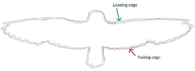
1
As this wing loading is so low, the owl has the ability to glide (i.e., fly without flapping its wings) at relatively low velocities, reducing the Reynolds Number (which is proportional to flow speed) of the air travelling over its wings and body. The Reynolds Number provides a measure of the nature of the flow of the air, and a lower value gives a more laminar flow, reducing these ‘disturbances’/this turbulent airflow that causes production of sound, so the optimal shape and large size of the owls wings relative to its body, and the capabilities these give, contribute to noise reduction to great effect.
2. The “velvety”/ “downy” surface texture of the owl’s wings
Run your fingers over an owl’s feathers and you will find the feel to be incredibly soft and smooth, velvety to be more precise (I’ve never done this, but I can assume this is what it feels like). To simplify why this is, I can say that the feathers of owls are adapted such that the pennula (frayed, soft strands that layer the feather) are generally longer than for other birds’
feathers. This greater overall quantity of pennula as such results in the wings being much softer/velvety, which reduces the friction air experiences as it passes over the wings, reducing the amount of flow separation and subsequent turbulent flow occurring, reducing the amount of sound created by the air passing over the wing.
There are further studies into how the orientation and density of pennula on different regions of the wing contribute to its aerodynamic performance, and I can direct you back to Wagner (Wagner, et al., 2017), Jaworski and Peake (Jaworski & Peake, 2019) because I can’t explain this to you without potentially writing too much on things you will definitely not be interested in (unless, of course, you are, in which case find the articles on Google Scholar, or even just search them up!).
Though it could be hard to think of translating something like pennula to an aviation application, the idea of biomimicry to reduce surface friction has already been well investigated –think of the research put into how shark skin reduces the friction it experiences with the water (though the Fastskin tech by Speedo doesn’t actually mimic sharkskin, be careful!).
3. “Fringes” in the feather on the trailing edge of the owl’s wings
The study by Ffowcs Williams & Hall (Ffowcs Williams & Hall, 1970) is a solid baseline to understanding the noise generated by a trailing edge of an aerofoil travelling through a fluid, and the important idea to note from the study is that the sharp, rigid trailing edge and the noise resulting from the scattering of a boundary layer flowing over it takes a great significance in the total amount of sound produced by an aerofoil as it travels through a fluid.
Unconventionally, the trailing edge of owl wings and feathers are frayed – if you’ve ever picked up a pigeon feather say, and noticed the fact that each individual feather barb is aligned with adjacent barbs and doesn’t cross over any other barbs, you’d notice the difference between that and what you’d see on an owl feather. The tips of the barbs on owl feathers are separated because they lack hooklets that would hook each barb to the next barb – I hope that’s fairly easy to visualise.
The observed advantage of the fringes of adjacent barbs of adjacent feathers can begin to interlock, essentially interlocking the feathers themselves. This enables the formation of one single, uninterrupted trailing edge, instead of multiple trailing edges formed by each feather. The reduction in the number of trailing edges reduces the amount of sound created.
4. Serrations at the leading edge of the owl’s wings
“Serrations” (formed by detached tips of feather barbs, in a similar way to the fringes, but with more organisation, like a comb) at the leading edge of the owl wing have probably been the most researched and considered features for translation to the aviation industry.
The serrations alter the airflow at one of the most primary sections of the flow over the wing, and testing with artificial replicas of these serrations have found that they reduce the separation region of the air coming off of the wing. Figure 2 will show what the separation region
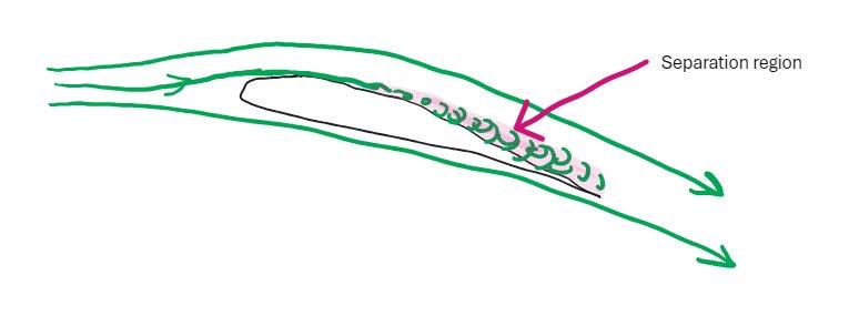
Figure 2 - Separation region shaded in light pink
actually is, which is the region of turbulent air formed behind the point of airflow separation from the wing, a further explanation of which can be found at the Wikipedia link in the references (Wikipedia, 2024).
By reducing the size of the region of separation and the subsequent turbulent flow, the noise produced by the wing is reduced.
That about covers everything about an owl’s adaptations to keeping itself as quiet in flight as possible but, naturally, it is likely that not everything has been discovered about these wonderful birds, which is what makes the whole study quite interesting – there is so much to learn from birds, new tricks and innovations to apply to what we have in the aviation industry. Take something that has already come out of the industry inspired by bird flight with the AEROGUST study, coordinated by the University of Bristol, and the resulting eXtra Performance Wing project by Airbus (your time to do your research).
I highly recommend that the next time you go out for a walk, or really anywhere with birds, and you spot a bird, consider what about them makes them as suited as possible to what they do, what they specialise in. It can be a very fulfilling investigation, because it’s great practise of the theory you may already know around aerospace engineering, and even other facets of engineering like mechanical engineering, and of course even Biology (if you do take that... odd subject). For example, my recent visit of Iceland took me to the puffins inhabiting the Vestmannaeyjar (Westman Islands), who I noticed have a curved wing shape as they glide that could potentially utilise the ground effect against the ocean or the gusts of wind that they would experience at the windiest point in Iceland (Figure 3, next page). There’s no guarantee they are made as such for this advantage, but it gets the brain going.
There is apparent potential here – I think it’s awesome!
Ewan Butterworth
Figure 3Credit: Oleg Tereshchenko
Sources:
BBC Earth, 2016. Experiment! How does an Owl fly so silently?. [Online] Available at: https://www.youtube.com/watch?v=d_FEaFgJyfA [Accessed 8 July 2024].
Ffowcs Williams, J. E. & Hall, L. H., 1970. Aerodynamic sound generation by turbulent flow in the vicinity of a scattering half plane. Journal of Fluid Mechanics, 40(4), pp. 657-670.
Jaworski, J. W. & Peake, N., 2019. Aeroacoustics of Silent Owl Flight. Annual Review of Fluid Mechanics, 28 August, pp. 395-420.
Johnson, D., 1997. Wing loading in 15 Species of North American Owls. Biology and conservation of owls in the Northern Hemisphere, pp. 553-556.
Lilley, G. M., 1998. A Study of the Silent Flight of the Owl. Hampton, American Institute of Aeronautics and Astronautics.
Wagner, H., Weger, M., Klass, M. & Schröder, W., 2017. Features of owl wings that promote silent flight. Interface Focus, 6 February, VII(1).
Wikipedia, 2024. Flow Separation. [Online]
Available at: https://en.wikipedia.org/wiki/Flow_separation [Accessed 21 July 2024].
P.S. the full article is reserved for next year :)
Cover picture: https://unsplash.com/photos/yellow-and-blue-airplane-on-sky-QbW7tAbzv0c
Inner cover picture (p1): https://unsplash.com/photos/white-and-black-plane-in-the-airduring-daytime-4LlQZoNC1Zw
Plane of the Week picture (p5): https://unsplash.com/photos/orange-and-yellow-plane-flying-in-the-sky-YEG2w5GNBXo
Articles picture (p43): https://unsplash.com/photos/a-fighter-jet-flying-through-a-blue-skyBwPb3udPu6k
If you’ve managed to get this far, then we ssincerely hope you’ve enjoyed your flight aboard the Aviation Jounal 2024! That’s it for this year, we hope to see you soon :)