Design calculations for Micro Ducts
4. Insulation performance
(Unit: W/m•K)
Design calculations for Micro Ducts
4-1. Thermal Average of both surface temperatures (°C)
conductivity
0
10
20
30
40
50
Micro Duct 64K-25mm
0.031
0.033
0.035
0.036
0.037
0.040
Glass wool 24 K-25 mm
0.034
0.036
0.038
0.041
0.042
0.044
Product-specific
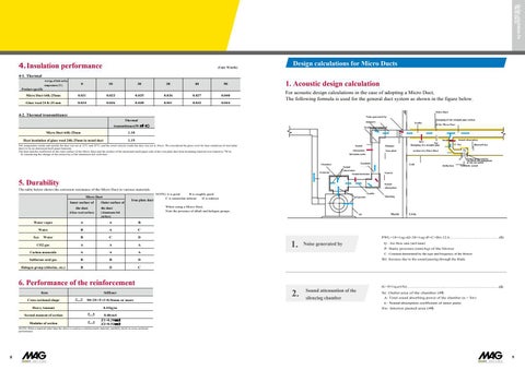
1. Acoustic design calculation For acoustic design calculations in the case of adopting a Micro Duct, The following formula is used for the general duct system as shown in the figure below.
4-2. Thermal transmittance Thermal transmittance(W/㎡・ K ) Micro Duct 64K-25mm
1.10
Heat insulation of glass wool 24K-25mm in metal duct
1.19
The temperature inside and outside the duct was set at 12°C and 32°C, and the wind velocity inside the duct was set at 10m/s. We considered the glass wool for heat insulation of steel plate ducts to be an aluminum kraft paper laminate. The heat transfer coefficient of the outer surface of the Micro Duct and the surface of the aluminum kraft paper side of the iron plate duct heat insulating material was treated as 7W/m · K considering the change of the emissivity of the aluminum foil with time.
5. Durability The table below shows the corrosion resistance of the Micro Duct to various materials. Micro Duct Inner surface of the duct
Outer surface of
Iron plate duct
When using a Micro Duct, Note the presence of alkali and halogen groups.
the duct
(Glass wool surface)
(Aluminum foil surface)
Water vapor
A
A
B
Water
B
A
C
B
C
D
CO2 gas
A
A
A
Carbon monoxide
A
A
A
Sulfurous acid gas
B
B
D
Halogen group (chlorine, etc.)
B
D
C
Sea
Water
NOTE) A is good B is roughly good C is somewhat inferior D is inferior
PWL=10×ℓog10Q+20×ℓog10P+C+Bri-12.6 .............................................................. (1)
1.
Noise generated by
P: Static pressure (mmAq) of the blower C : Constant determined by the type and frequency of the blower Bri: Increase due to the sound passing through the blade
6. Performance of the reinforcement Item
Stiffener
Cross-sectional shape
50×25×5×3×0.5tmm or more
Heavy Amount
0.41kg/m
Second moment of section
0.40cm4
Modulus of section
Z1=0.30㎝3 Z2=0.52㎝3
Q : Air flow rate (m3/min)
ΔL=10×ℓog10(A/Se).................................................................................................................... (2)
2.
Sound attenuation
Se: Outlet area of the chamber (㎡) A: Total sound absorbing power of the chamber (α × Sw) α : Sound absorption coefficient of inner paste Sw: Interior pasted area (㎡)
NOTE) When a material other than the above is used as a reinforcement material, carefully check its cross-sectional performance.
8
9


