
4 minute read
Micro Duct performance 1. Acoustic Design Calculations


4. Thermal insulation calculation
The heat loss (heat acquisition) of the Micro Duct is calculated by the following equation.
Qd=0.24γQΔt 1-( e0.24γQ)
Qd : Heat loss (heat acquisition) of the duct (W/h) γ : Specific weight of air (kg/m3) Q : Ventilation volume of duct (m3/h) Δt : Temperature difference betw een the inside and outside of the duct at the start point of the duct (°C) K : Thermal Transmission Rate of Duct (W/㎡•K) S : Circumference of duct (m) ℓ : Duct length (m)
The heat transfer coefficient of the Micro Duct is 0.95W/㎡•K. For the values for steel plate ducts, refer to the section on insulation performance.
Calculation example
Air volume (㎥/h) Q
AB (steel plate) 2,000

2,000
1,000
1,000 Temperature difference inside / outside (℃)
Δt
20 ※1
20
20
20 Duct circumference (m) S
1.3
1.3
1.0
1.0 Duct length (m) ℓ

2
3
9
3
Thermal transmittance
(W/㎡・ K)
K
1.19 ※2
1.10 ※3
1.10 ※3
1.10 ※3


5. Strength design calculation
The strength calculation without reinforcement of the square duct is performed by the following formula (positive pressure).
p=83400×-a2
p : Total pressure in duct (mmAq)
σ : Allowable stress (kg/c㎡) a : Length of long side of duct (cm)
The allowable stress of 400×250mm in the P17 duct system is σ=0.96kg/c m2 (P17), so
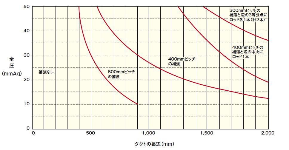
As a result, the total resistor calculated on the duct system on page 17 is 7.26mmAq, so it is considered safe enough. In addition, the 250×250mm duct is similarly obtained as 120mmAq. When using at a total pressure exceeding the value calculated by this formula, reinforce the outer material with a reinforcing material. Refer to the figure below for the relationship between the side length of the supply duct (square duct) that is reinforced with a reinforcing material ( 50 × 25 × 5 × 3 × 0. 5t or more) on the outside and the allowable pressure.
50
40
30
Total pressure Total pressure (mmAq)(mmAq) No reinforcement 600mm pitch 20 No reinforcement reinforcement
10
400mm pitch 400mm pitch reinforcement
reinforcement
Reinforcement of 300 mm pitch and one rod for each trisection point
With a pitch of 300 mm 2 Each od 1 pc.(
With In the cent er of H
otal of wo)
2 Reinforcement of 400 mm pitch and one rod in the center of the side
Rod
0
0 500 1,000 Long side of duct (mm)
Relationship between supply duct side length and allowable pressure Duct long side (mm)
1,500 2,000
For negative pressure (return duct), calculate σ (allowable stress) in the equation as 0.96 × 0.7 = 0.67kg/c㎡. Note that 0.7 is a coefficient for load types when using with negative pressure. When using the above figure for a return duct (inner roll reinforcement with reinforcing material), replace the value with a value obtained by multiplying the total pressure by static pressure and the length of the side by 0.8.
Processing and assembly of Micro Ducts
This section explains the manufacturing procedure of "one-board" which is often used as the most common method of manufacturing rectangular straight ducts by photography.
After drawing a line on the glass fiber surface of the duct board, place a ruler so that this line is at the center of the tool, and cut three grooves with the gold color tool.

Cut the other end into a male shape with the purple tool.

2.
Cut the duct board to the length obtained by adding 210mm to the total value of the four sides of the dimension in the duct to make a 40mm flap, and then cut this part into a female form with the silver tool.

5.
Lap aluminum foil flaps and hit the staple.

3.
Cut one end of the duct perpendicular to the flap into a female form with the silver tool.

6.
Use a special tape to friction-crimp the joint completely using a spatula.

Precautions for Use
1. Do not use at wind speeds exceeding the allowable range (13m/s for square ducts and 15m/s or more for round ducts) and at full pressure (more than 490Pa for square ducts and 590Pa for round ducts).

2. Do not operate the air conditioner with the damper fully closed when using the product on the upstream side before FD or VD. 3. Contact CKD when using the product on the primary side from VAV, etc.
4. Do not use at temperatures exceeding the allowable range.
5. Do not use outdoors without reinforcement and waterproof covering.
6. Avoid direct contact with concrete.
7. After hanging the duct, do not hang ladder or climb on it. (Attach a caution label after installation.) 8. After installation, provide about 30 minutes of spare ventilation before use. 9. Water wetting is strictly prohibited! Do not use if wet.

