Design calculations for Micro Ducts
4. Thermal insulation calculation
5. Strength design calculation
The heat loss (heat acquisition) of the Micro Duct is calculated by the following equation.
The strength calculation without reinforcement of the square duct is performed by the following formula (positive pressure).
Qd=0.24γQΔt 1-e-
p=83400×-a2
(
0.24γQ)
p : Total pressure in duct (mmAq)
Qd : Heat loss (heat acquisition) of the duct (W/h) γ : Specific weight of air (kg/m3)
σ : Allowable stress (kg/c㎡)
Q : Ventilation volume of duct (m3/h)
a : Length of long side of duct (cm)
Δt : Temperature difference betw een the inside and outside of the duct at the start point of the duct (°C) K : Thermal Transmission Rate of Duct (W/㎡•K)
The allowable stress of 400×250mm in the P17 duct system is σ=0.96kg/c m2 (P17), so
S : Circumference of duct (m) ℓ : Duct length (m)
The heat transfer coefficient of the Micro Duct is 0.95W/㎡•K.
As a result, the total resistor calculated on the duct system on page 17 is 7.26mmAq, so it is considered safe enough. In addition, the 250×250mm
For the values for steel plate ducts, refer to the section on insulation performance.
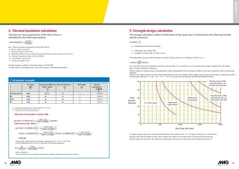
duct is similarly obtained as 120mmAq. When using at a total pressure exceeding the value calculated by this formula, reinforce the outer material with a reinforcing material. Refer to the figure below for the relationship between the side length of the supply duct (square duct) that is reinforced with a reinforcing material ( 50 × 25 × 5 × 3 × 0. 5t or more) on the outside and the allowable pressure.
Calculation example Air volume (㎥/h) Q
Temperature difference inside / outside (℃)
Duct circumference (m) S
Duct length (m) ℓ
Thermal transmittance (W/㎡・ K ) K
Δt
AB (steel plate)
2,000
20 ※1
1.3
2
1.19 ※2
BC
2,000
20
1.3
3
1.10 ※3
CDE
1,000
20
1.0
9
1.10 ※3
CF
1,000
20
1.0
3
1.10 ※3
Reinforcement of 300 mm pitch and one rod for each trisection point
50
With a pitch of 300 mm 2 Each 1 pc.( otal of
40
od
30
Total Total pressure pressure (mmAq) (mmAq)
400mm pitch reinforcement
400mm pitch
600mm pitch reinforcement
No reinforcement
20
No reinforcement
wo)
2 Reinforcement of 400 mm pitch and one rod in the center ofInthe side With
reinforcement
the cent er of H
Rod
10
0 0
500
1,000
1,500
2,000
Long side of duct (mm)
(
)
(
)
Relationship between supply duct side length and allowable pressure
Duct long side (mm)
(
)
For negative pressure (return duct), calculate σ (allowable stress) in the equation as 0.96 × 0.7 = 0.67kg/c㎡. Note that 0.7 is a coefficient for load types when using with negative pressure. When using the above figure for a return duct (inner roll reinforcement with reinforcing material), replace the value with a value obtained by multiplying the total pressure by static pressure and the length of the side by 0.8.
18
19


