


HEALTH & SAFETY
(To be read in conjunction with Structural engineer Structural Designers Risk Assessment & Method Statements)
A) It is important that the contractor alerts the client and design team if there are any trades or skills required from the drawings and other contract documents, that are not within the immediate expertise of the contractor.
B) The Contractor is responsible for the stability of the existing structure and all retained earth works, both on the site and on adjoining sites and must take all necessary precautions to safeguard their stability. All temporary works and the stability of the works in general during construction is the responsibility of the Contractor.
C) The Contractor is to obtain relevant C.O.S.H.H. information with regards to the materials he proposes to use in the works and is to ensure that all operatives are aware of he requirements stated in the C.O.S.H.H. regulations
D) The Contractor is to comply with the requirements of the Health & Safety at Work Act 1994 in terms of the Employer's responsibilities.
E) The Contractor must pay particular attention to health and safety matters and methods of working. The Contractor is to decide upon the sequence of working and must use best practice at all times with particular care when working at height and below ground,when dismantling, demolishing and installing emporary support for inserting new elements to support existing structure.
F) The contractor should advise the client and consultant team if they become aware of any particular health and safety concerns or if they discover any deleterious materials such as asbestos etc. We are not experts in matters such as deleterious materials and are not employed to advise
G) Structural engineer are not employed by the client to provide contract administration or general supervision and may not be aware of the works and general progress on site. It is essential that the contractor alert both the client and Structural engineer. if any unforeseen elements or material design variations arise, leading to any changes to the structural drawings/specifications/scope of work.

PARTY WALL ACT
On the 1st July 1997, a new act, The party Wall etc Act 1996 came into force. This Act requires a building owner to notify, and obtain formal agreement from, any adjoining owner, where the building owner proposes to
1) Carry out works to an existing party wall

2) Build on the boundary with a neighbouring property
3) Carry out groundworks/excavation within 3 meters of a neighbouring building if deeper than neighbours foundations or excavation is within 6 meters of a neighbouring building where the excavation will cut a line drawn downwards at 45° from the bottom of the neighbours foundation.
Notification and agreements under this Act are the responsibility of the building owner and are quite separate from Building Regulations, or Planning controls. Building Control will assume that the applicant has obtained any necessary agreements with the adjoining owner, and nothing said or implied by Building Control should be taken as removing the necessity for the building owner to comply fully with the Act.
may be varied slightly, and will be detailed to a greater degree during the precontract period. It is usual for a contingency sum to be included for such circumstances.
B) This drawing to be read in conjunction with a relevant drawings produced by the Architect M&E Public Health Engineers and Structural engineer.
C) Structural engineer drawings are not to be scaled to obtain dimensions. All dimensions are to be obtained from site measurement.
D) All setting out information and levels are to be obtained from the Architect's drawings.


E) The structural design has been prepared to comply with part A of the Building Regulations. Design details required to comply with other non-structural parts of the Building Regulations are the responsibility of the Architect, or others.
F) Details of all non-structural items, i.e. ventilation, insulation, services, waterproofing, fire protection, dampproofing finishes, sound separation requirements etc. are to be obtained from the Architect's or M&E Public Health Engineers drawings.
G) The contractor is to inform the Architect and Structural engineer of any discrepancies shown on the drawings with regard to the size, position and arrangement of the existing structure and associated elements.
H) All structural work is to be to the satisfaction of the Building Inspector, in addition to our own requirements. The Contractor is responsible for contacting Building Control in good time to allow for all structural works to be inspected. We cannot anticipate the specific requirements of the Building Inspector, which may be additional to our own requirements. It is essential that our designs/drawing details are not varied by discussion with the Building Control Officer or other persons, without our prior discussion and agreement,eg reduced foundation depths from those shown on our drawings, or beams omitted etc. This is very important.
I) The Contractor is to inform Structural engineer of all builders work holes required to be formed in structural members (e.g. holes in steel beams, floor joists etc.) and await Structural engineer comments prior to ordering materials, installation of member or formation of holes.
J) All works are to be in accordance with the current British Standard and Building Regulations.

K) The Contractor must exercise due care and attention to any disturbed ground with regards to contamination or pollution o deleterious material.

184900 184900 516700 516800 516700 516800 01020 CF BooConstGLAslyCon &LBBdy Def GREENGATE 90 16 2 108 32 1 6 a 57 31 104 58 1 24 18 5 5m UP Sunse Su e N N ORCHARDGATE 5420 900 19.5 m² KITCHEN DINING 1775 15.7 m² SITTING ROOM 870 810 1700 1000 860 900 FF 3860 2100 900 16.1 m² GARDEN ROOM 660 2200 660 3110 1160 730 1600 410 2740 2318 1200 2355 755 1550 936435 4000 936 845 3935 5420 710 4000 710 961 810 129 1900 750 1512 1200 2735 3520 573 2729 217 3 BR-1032 BR-103 1013 6125 1662 3060 6513 605 GROUND FLOOR 63.7m2 FIRST FLOOR 45.8m2 Tot. 139.44m2 PROPOSED GIA (m2) LOFT 29.94m2 Written dimensions to be taken in preferences to scaled dimensions. The Contractor is responsible for checking all dimensions before work starts. All work is to be carried out to the requirements, and to the satisfaction of the Local Authority. These drawings are for planning purposes only. Dimensions Local Authority Rev Date Description Made Checked Drawing Status: FOR APPROVAL Client Project Drawing Title Drawn/Design Scales: AS SHOWN @ A1 Drawing No Date Rev RPR PLANNING Office 5, 37 Stanmore Hill London, HA7 3DS. Tel: Mobile: Web: Email: 078 9661 7854 www. rprplanning.co.uk info@rprplanning.co.uk 25/09/2023 09:57:31 AM C:\Users\saada\Desktop\RPR PLANNING\99 ORCHARD GATE \2023.06.2399 Orchard GateBuilding Regulation .rvt99 Orchard Gate, Greenford UB6 0QN OS MAP, BLOCK PLAN - PROPOSED LAYOUT GROUND FLOOR PLAN 06/07/17 BR-100 SCALE: 1 : 400 @ A3 1 : 200 @ A1 PL -Block Plan SCALE: 1:2500 @ A3 1 1250 @ A1 PL -OS MAP VISUAL SCALE 1:50 @ A1 5m 1m 4m 3m 2m 0m 1:100 @ A3 VISUAL SCALE 1:200 @ A1 20m 4m 16m 12m 8m 0m 1:400 @ A3 VISUAL SCALE 1:1250 @ A1 125m 25m 100m 75m 50m 0m 1:2500 @ A3 SCALE: 1 100 @ A3 1 : 50 @ A1 PL -Proposed ground floor NOTES - STRUCTURAL & ARCHITECTURAL These are important Specification Notes applicable unless specifically noted otherwise on Structural engineer or Architects Drawings or specification GENERAL It is essential the builder reads these notes. A) This drawing has been prepared with the scheme design work at an early stage and whilst much of the skeletal structure is designed the precise nature of the detailed works has yet to be developed and thus the works
LINTELS AND BEAMS
To be proprietary galvanized steel lintels to BS5977:1983 in external cavity wall with flexible DPM to stop ends and weepholes at 450mm c/c min. 2No per lintel. All lintels built into externa walls to be insulated to achieve 1.2W/m². Minimum end bearing of 150mm with DPM overlapping end of lintel by 150mm. Galvanized stee or pre-cast concrete lintels to be provided over openings in internal load bearing walls. For manufacturer and lintel type, refer to drawing. steel beams to be provided in sizes and weights as described by Structural Engineer and as shown on working drawings. Beams built into external brickwork to be coated with bituminous paint.
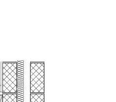
STUD WALLS AND ROOF SLOPE
Perimeter and Purlin walls to be 50 x 100mm vertica studs at 400mm c/c on 50 x 100mm head and sole plate. All cavities to be filled with 85mm ECO
THERM insulation, faced with 2x12.5mm plasterboard and skim.
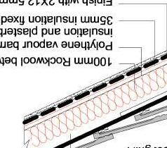
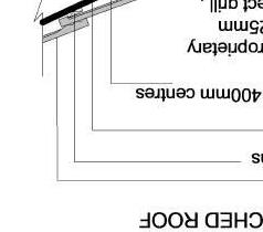
Internal partitions to be formed from 47 x 100mm vertical studs at 400mm c/c with cross noggins on 50 x 100mm plates and faced with 12.5mm plasterboard and skim. Stair enclosure to have 2x12.5mm plasterboard both sides to achieve 30mins fire resistance. All nternal wall cavities to be filled with 100mm ROCKWOOL to achieve the requirement of A.D. PART E 2003 Existing roof slopes within conversion to have 35mm CELOTEX insulation fixed to underside of rafters with 100mm CELOTEX XR4000 insulation cut between rafters, maintaining 50mm air gap above insulation and roof covering by fixing 38mm x 50mm timber batterns to he underside of the rafters. Polythene Vapour Barrier to warm side of nsulation with 2x12.5mm plasterboard and skim internally.
to drawings.
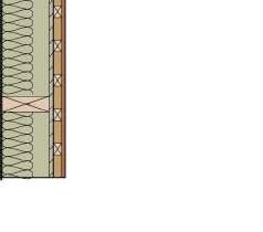
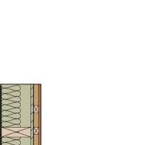
EXTERNAL WALL CONSTRUCTION (BRICK AND BLOCKWORK)
Cavity construction overall 297.5mm (UNO - refer to drawing) comprising of inner leaf blockwork 100mm thick, CELCON SOLAR or similar and approved with 13mm lightweight plaster finish internally. Cavity to be partially filled with 45mm Celotex CW4000 cavity bats insulation. Max cavity overall 95mm (50mm clear void to be maintained) to comply with BS6676 Part 1: 1986 Thermal insulation) and installed on site in accordance with BS6676 Part 2: 1986. External leaf constructed from facing brickwork to match the existing approved by the Local Authority Planning Department above class B semiengineering bricks above DPC. 'U' value of 0.21W/m²K.
Stainless steel wall ties at max. 900 mm horizontal and 450mm vertical centers with 225mm vertical centers at reveals, within 360mm of openings. Cavities to be closed around openings with THERMABATE PVC-U cavity closures or similar and approved Agreement Certificate No. 91/2648. Build in pitch polymer cavity trays with stop ends as necessary. Flashing's at all abutments with Code 4 lead. Horizontal DPC'S to be a minimum 150mm above GL and overlapped at junctions a minimum 100mm.
GROUND FLOOR CONSTRUCTION - Ground bearing slab - Refer to drawings
New base to be formed by braking up existing surface and stripping top soil to a suitable depth for 150mm hardcore. This is to comprise of clean broken brick cuts, over hardcore lay minimum 50mm compact and rolled sand binding with 1200 gauge polythene sheet damp-proof membrane laid over, or 1000 gauge if to agreement certificate and PIFA standards. All joints to be overlapped 150mm and sealed with mastic joint tape and completed with polythene jointing tape between overlapping sheets. DPM to be turned up to overlap with new and existing DPC if applicable minimum 50mm.
Pour 150mm thick 1:2:4 concrete with reinforcement mesh if Local Authority or
Structural Engineer's specification to BS5328 mix ST4 if required. Floor finish to be either 75mm sand/cement screed 1:3 mix on 75mm hick CELOTEX
GA4000, dressed up the inner face of the inner leaf (Thickness to be at least that of the plaster finish and skirting board) or 105mm JABLITE JABFLOOR
PREMIUM insulted floor grade chipboard or similar and approved (Allowing 10-12mm gap around all perimeter edges). Complying with BS:6203 and 5669: part 1 to 5. Achieves 0.22w/m²k
SUSPENDED TIMBER FLOOR AND CEILING
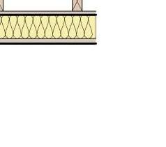
Place new timber floor joists to Structural Engineers requirements and specification. Use 100mm Rockwool Roll Bat insulation placed between joists. Use 22mm chipboard (V313) flooring over to achieve 30mins fire resistance and meet sound requirement of Part E.
PITCHED ROOF CONSTRUCTION
Tiles type and colour to match the existing on 25 x 38mm SW battens on
TYVEK SUPRO fully breathable roofing felt on timber as specified by Structural Engineer - refer to drawings. Pitched roof (sloping roof) to be insulated, provide 100mm thick CELOTEX GA4000 insulation between rafters and 35mm fixed underneath rafters. Fix polythene (1000 gauge), vapour control layer including air leakage (permable underlay) barrier with 2x12.5mm plasterboard with 3mm plaster skim Achieves 0.18W/m²K.
DN UP DN 14.1 m² BEDROOM 2 11.8 m² BEDROOM 1 3.9 m² BATHROOM 7.4 m² BEDROOM 3 2110 1660 2360 2555 800 2965 3.4 m² HALL 660 660 GREEN ROOF 640 4460 3365 1265 760 85 810 1915 1400 1400 3515 2350 810 1300 1550 45 760 185 760 805 1595 760 45 2748 217 250 3 BR-1032 BR-103 850 950 3755 1665 1665 2m height 4.3 m² EN-SUITE 30.7 m² BEDROOM GREEN ROOF 700 700 6525 5125 1291 717 1474 3635 4515 1851 1755 710 860 1474 731 2065 855 4365 3 BR-1032 BR-103 3286 GROUND FLOOR 63.7m2 FIRST FLOOR 45.8m2 Tot. 139.44m2 PROPOSED GIA (m2) LOFT 29.94m2 Written dimensions to be taken in preferences to scaled dimensions. The Contractor is responsible for checking all dimensions before work starts. All work is to be carried out to the requirements, and to the satisfaction of the Local Authority. These drawings are for planning purposes only. Dimensions Local Authority Rev Date Description Made Checked Drawing Status: FOR APPROVAL Client Project Drawing Title Drawn/Design Scales: AS SHOWN @ A1 Drawing No Date Rev RPR PLANNING Office 5, 37 Stanmore Hill London, HA7 3DS. Tel: Mobile: Web: Email: 078 9661 7854 www. rprplanning.co.uk info@rprplanning.co.uk 25/09/2023 09:57:33 AM C:\Users\saada\Desktop\RPR PLANNING\99 ORCHARD GATE \2023.06.2399 Orchard GateBuilding Regulation .rvt99 Orchard Gate, Greenford UB6 0QN Layout - PROPOSED FIRST FLOOR AND LOFT PLAN 11/22/21 BR-101 VISUAL SCALE 1:50 @ A1 5m 1m 4m 3m 2m 0m 1:100 @ A3 SCALE: 1 100 @ A3 1 : 50 @ A1 PL -Proposed first floor SCALE: 1 100 @ A3 1 50 @ A1 PL -Proposed Loft WALL CONSTRUCTION Load bearing bricks and blocks have a minimum crushing strength of 21N/mm2 and 2.8N/mm2 or equivalent, unless otherwise noted on the drawings and as specified by the Structural Engineer - refer
new habitable rooms to have an openable window with at least 0.33m² clear opening.
Self contained mains operated interlinked smoke alarms (BS5446) and fitted with battery backup to be provided to all landing and hall ceilings shown thus
FIXINGS
A) All joist hangers, frame clips, restraint straps, fixings, bolts and masonry support systems (using casting slots) to be installed in strict accordance with the manufacturers' instructions.
B) All new timber joists and/or beams are to be supported using joist hangers unless noted otherwise.
C) Seek Engineer's advice on type of joist hanger used, if less than 675mm of set masonry present above position of joist hanger. D) Vertical restraint straps to be (100+900)long 30x2.5 galvanised mild steel. To be fixed at 1.5m centres using 6No 4.0dia x 75mm long corrosion resistant nails unless shown otherwise on drawings.
E) Lateral restraint straps to be (150+1450)long a roof and (150+1050)long at floors and to be 30x5 galvanised mild steel. To be fixed at 1.2m centres generally (2.0m centres at first floor) using 5No 12x50 wood screws.
LATERAL SUPPORT AND STRUCTURAL FIXINGS
Galvanized mild steel anchor straps of cross-section 5 x 30mm to be provided at maximum 2.0m c/c
At rafter level, adjoining gable and separating walls and at ceiling tie level at maximum 2000mm centers. Anchor straps positioned at roof level using noggins to block between rafters (minimum 38 x 75mm) and packing pieces to block between rafter and wall. straps to span and to be fixed to at least 3 number rafters and to turn down cavity by a minimum of 100mm hard against face of inner skin.
Wall plates to be held down with galvanized m.s. straps 5 x 30 x 1000mm at maximum 2.0m c/c. Straps to be plugged and screwed to walls with 8 x 50 countersunk screws into solid blockwork, not joints.
TIMBER
A) All structural timber to be in accordance with BS 5268 for workmanship and quality and BS 4471 for sizes.
B) All structural timber to be strength class C16 or better and to have a moisture content not more han 12%
C) All new timber to be treated and preserved in accordance with the Architect's details.
D) All timbers forming beams are to be bolted together using M12 bolts at 600 centres
E) New floor and roof joists spanning more than 2.5m to be restrained by solid noggins along their centre, securely nailed nto position. New joists spanning more than 4.5m to be restrained by solid noggins at third spans.
F) Notches in joists to be formed by sawing down to a drilled hole. To be a maximum depth of 0.125 x joist depth and between 0.07 and 0.25 x span from support.
G) Holes in joists to be at mid-depth with a max diameter of 0.25 x joist depth, at minimum centres of 3x largest hole diameter and spaced between 0.25 and 0.4 x span from support.
H) Holes and notches should not be located near to knots or other defects and should be a minimum of 100mm apart in the same joist.
Holes and notches in rafters, struts and truss members are not permitted.
J) Separating floors Structural sizes indicated on the drawings are to meet Part A1 of the Building Regulations and may not comply with other parts e.g. Part E for sound separation.
VELUX WINDOWS
All windows to be double glazed (3 x 16 x 4 - low E PROTEX STAR) and fitted in accordance with manufacturers instructions, trimmed both sides with doubled up rafters (To Structural Engineers Specification) with trimmers above and below the velux.
WINDOWS AND DOORS
All new windows and doors to be of UPVC, or by specialist to match the existing as close as possible.
All double glazed to achieve 1.6W/m²K. (6mm Optifloat /16mm argon filled cavity 6mm PILKINGTON K glass) achieves 1.5W/m²K Opening areas of windows and doors to excess 1/20th of the room floor areas; some part opening to be minimum 1.75 meters above floor level. Trickle vents are to be inserted in frames of windows/doors to achieve 8000mm² controllable free ventilation to habitable rooms, and 4000mm² kitchens, bathrooms and en-suites.
PARTY WALL ACT
On the 1st July 1997, a new act, The party Wall etc Act 1996 came into force.
This Act requires a building owner to notify, and obtain formal agreement from, any adjoining owner, where the building owner proposes to
1) Carry out works to an existing party wall
2) Build on the boundary with a neighbouring property
3) Carry out groundworks/excavation within 3 meters of a neighbouring building if deeper than neighbours foundations or excavation is within 6 meters of a neighbouring building where the excavation will cut a line drawn downwards at 45° from the bottom of the neighbours foundation.
Notification and agreements under this Act are the responsibility of the building owner and are quite separate from Building Regulations, or Planning controls. Building Control will assume that the applicant has obtained any necessary agreements with the adjoining owner, and nothing said or implied by Building Control should be taken as removing the necessity for the building owner to comply fully with the Act.
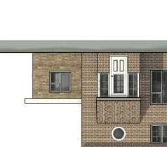
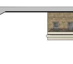
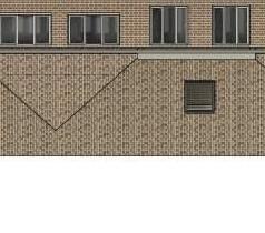
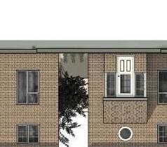
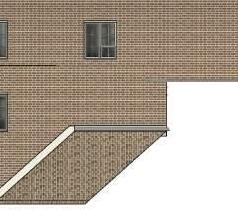
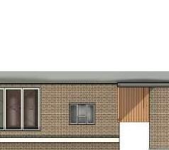
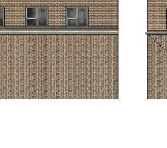
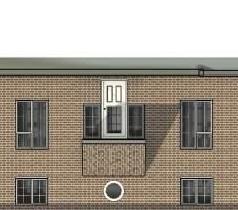
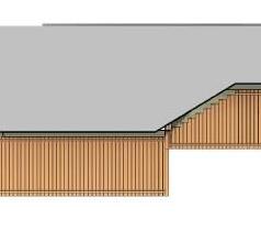
BR-103 2 BR-103 700 700 5125 BR-1032 BR-103 Written dimensions to be taken in preferences to scaled dimensions. The Contractor is responsible for checking all dimensions before work starts. All work is to be carried out to the requirements, and to the satisfaction of the Local Authority. These drawings are for planning purposes only. Dimensions Local Authority Rev Date Description Made Checked Drawing Status: FOR APPROVAL Client Project Drawing Title Drawn/Design Scales: AS SHOWN @ A1 Drawing No Date Rev RPR PLANNING Office 5, 37 Stanmore Hill London, HA7 3DS. Tel: Mobile: Web: Email: 078 9661 7854 www. rprplanning.co.uk info@rprplanning.co.uk 25/09/2023 09:57:34 AM C:\Users\saada\Desktop\RPR PLANNING\99 ORCHARD GATE \2023.06.2399 Orchard GateBuilding Regulation .rvt99 Orchard Gate, Greenford UB6 0QN Layout - PROPOSED ROOF PLAN - FRONT AND REAR ELEVATION 11/22/21 BR-102 VISUAL SCALE 1:50 @ A1 5m 1m 4m 3m 2m 0m 1:100 @ A3 SCALE: 1 100 @ A3 1 50 @ A1 PL -Proposed rear elevation SCALE: 1 100 @ A3 1 50 @ A1 PL -Proposed Front elevation SCALE: 1 100 @ A3 1 : 50 @ A1 PL -Proposed Roof FIRE PRECAUTIONS (2010) All doors marked ** to achieve FD20 standard. However, if the doors are found to be unsuitable for such treatment they wil be replaced with new FD20 doors. Door stops to be upgraded or replaced to achieve 25mm x 35mm glued and screwed to door lining. Door glazing and fanlights within the stair enclosure to be fitted with 6mm Pilkington PYROSTOP glass. Any internal wall glazing within the stair enclosure to be changed to 15mm Pilkington Pyrostop glass. All
with BS EN 845-1 at max 2.0m centres, straps to be taken across minimum 3 no. joists. Straps to be built into walls. Provide 38mm wide x ¾ depth solid noggins between oists at strap positions.
ROOF LIGHTS Min U-value of 1.6 W/m²K.
Roof-lights to be double glazed with16mm argon gap and soft low-E glass. Window Energy Rating to be Band C or better. Roof ights to be fitted in accordance with manufacturer's instructions with rafters doubled up to sides and suitable flashings etc
Rooflights electrically operated with rain sensors. Center pivot. Internal colour white, External RAL colour to be confirmed.Contractor to discuss samples with Client prior to ordering.
STAIRS
Dimensions to be checked and measured on site prior to fabrication of stairs.
Timber stairs to comply with BS585 and with Part K of the Building Regulations. Max rise 220mm, min going 220mm. Two risers plus one going should be between 550 and 700mm. Tapered treads to have going in centre of tread at least the same as the going on the straight. Min 50mm going of tapered treads measured at narrow end. Pitch not to exceed 42 degrees. The width and length of every landing should be at least as great as the smallest width of the flight. Doors which swing across a landing at the bottom of a flight should leave a clear space of at least 400mm across the full width of the flight. Min 2.0m headroom measured vertically above pitch line of stairs and landings. Handrail on staircase to be 900mm above the pitchline, handrail to be at least one side if stairs are less than 1m wide and on both sides if they are wider. Ensure a clear width between handrails of minimum 600mm. Balustrading designed o be unclimbable and should contain no space through which a 100mm sphere could pass. Allow for all structure as designed by a Structural Engineer.
NEW WINDOWS New windows to be double glazed with 16mm argon gap and soft coat low-E glass. Window Energy Rating to be Band C or better and to achieve U-value of 1.6 W/m²K.
ABOVE GROUND DRAINAGE
All new above ground drainage and plumbing to comply with BS EN
12056-2:2000 for sanitary pipework. All drainage to be in accordance with part H of the Building Regulations. Wastes to have 75mm deep anti vac bottle traps and rodding eyes to be provided at changes of direction Size of wastes pipes and max length of branch connections (if max length is exceeded then anti vacuum traps to be used) Wash basin - 1.7m for 32mm pipe 4m for 40mm pipe
Bath/shower - 3m for 40mm pipe 4m for 50mm pipe W/c - 6m for 100mm pipe for single WC
All branch pipes to connect to 110mm soil and vent pipe terminating min 900mm above any openings within 3m. Or to 110mm upvc soil pipe with accessible internal air admittance valve complying with BS EN 12380, placed at a height so hat the outlet is above the trap of the highest fitting. Waste pipes not to connect within 200mm of the WC connection. Supply hot and cold water to all fittings as appropriate.
EXISTING STRUCTURE
Existing structure including foundations, floor, beams, walls, roof and lintels are to be exposed and checked for adequacy prior to commencement of work and as required by the Building Control Officer.
JULIET BALCONY & INTERNAL BALUSTRADE
Guarding to be a minimum of 1100mm(Balcony) & 900mm (internal balustrade) above the finished floor level and capable of resisting a lateral force applied to the top of 0.74KN/m. Balustrading designed to be unclimbable and should have no gap through which a 100 mm diameter sphere could pass.
EXTERNAL WALL CONSTRUCTION (BRICK AND BLOCKWORK) Cavity construction (refer to drawing) comprising o inner leaf blockwork 100mm thick, Thermalite Hi Strength blockwork or similar and approved with 13mm lightweight plaster finish internally. Cavity to be partially filled with 90mm Celotex CW4000 cavity bats insulation. Max cavity overall 140mm (50mm clear void to be maintained) to comply with BS6676 Part 1: 1986 Thermal insulation) and installed on site in accordance with BS6676 Part 2: 1986. External leaf constructed from facing brickwork to match the existing approved by the Local Authority Planning Department, above class B semi-engineering bricks above DPC, 100mm thick. Stainless steel wall ties at max. 900 mm horizontal and 450mm vertical centers with 225mm vertical centers at reveals, within 360mm of openings. Cavities to be closed around openings with THERMABATE PVC-U cavity closures or similar and approved Agreement Certificate No. 91/2648. Build in pitch polymer cavity trays with stop ends as necessary. Flashing's at all abutments with Code 4 lead. Horizontal DPC'S to be a minimum 150mm above GL and overlapped at junctions a minimum 100mm. Wall ties are spaced at 900mm horizontally and 450mm vertically, and 225mm vertically at penings
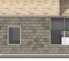
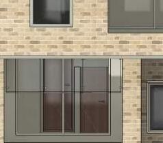
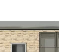
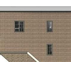
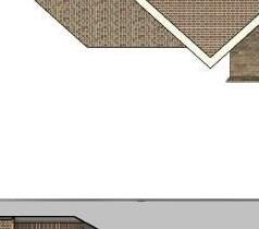
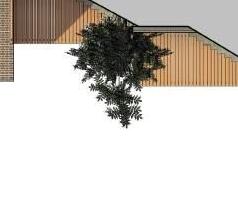
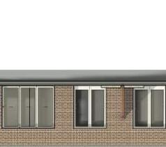
Obscure glazed windows 500 350 3 BR-103Obscure glazed windows 3 BR-10330.7 m² BEDROOM 11.8 m² BEDROOM 1 15.7 m² SITTING ROOM 16.1 m² GARDEN ROOM 80.3 m² PRIVATE GARDEN 2498 2500 2460 2460 2 BR-103 3 BR-10319.5 m² KITCHEN DINING 80.3 m² PRIVATE GARDEN 7.4 m² BEDROOM 3 4.3 m² EN-SUITE 30.7 m² BEDROOM 3.9 m² BATHROOM 3.4 m² HALL GF-05 8mm MS PLATE TO BE WELDED TO THE UNDERSIDE TO CARRY THE EXTERNAL BRICK LEAF LF-04 LF-03 LF-02 RB-01 Written dimensions to be taken in preferences to scaled dimensions. The Contractor is responsible for checking all dimensions before work starts. All work is to be carried out to the requirements, and to the satisfaction of the Local Authority. These drawings are for planning purposes only. Dimensions Local Authority Rev Date Description Made Checked Drawing Status: FOR APPROVAL Client Project Drawing Title Drawn/Design Scales: AS SHOWN @ A1 Drawing No Date Rev RPR PLANNING Office 5, 37 Stanmore Hill London, HA7 3DS. Tel: Mobile: Web: Email: 078 9661 7854 www. rprplanning.co.uk info@rprplanning.co.uk 25/09/2023 09:57:36 AM C:\Users\saada\Desktop\RPR PLANNING\99 ORCHARD GATE \2023.06.2399 Orchard GateBuilding Regulation .rvt99 Orchard Gate, Greenford UB6 0QN Layout - PROPOSED SIDE ELEVATIONS AND SECTIONS 11/22/21 BR-103 VISUAL SCALE 1:50 @ A1 5m 1m 4m 3m 2m 0m 1:100 @ A3 SCALE: 1 100 @ A3 1 : 50 @ A1 PL -Proposed side elevation SCALE: 1 100 @ A3 1 50 @ A1 PL -Proposed side elevation 2 INTERMEDIATE FLOORS To comply sound insulation as section detail on BR-009 Intermediate floor to be 25mm t&g flooring grade chipboard or floorboards laid on C24 joists (see engineer's calculation for sizes and details). Lay 100mm Rockwool mineral fibre quilt insulation min 10kg/m³ or equivalent between floor joists. Ceiling to be 12.5 Gyproc FireLine plasterboard with skim plaster set and finish. Joist spans over 2.5m to be strutted at mid span using 38 x 38mm herringbone strutting or 38mm solid strutting (at east 2/3 of joist depth). In bathroom flooring to be moisture resistant grade in accordance with BS7331:1990. Identification marking must be laid upper most to allow easy identification. Provide lateral restraint where joists run parallel to walls, floors are to be strapped to walls with 1000mm x 30mm x 5mm galvanised mild steel straps or other approved in compliance
SCALE: 1 100 @ A3 1 50 @ A1
SCALE: 1 : 100 @ A3 1 50 @ A1
PL -Proposed Section 2
PL -Proposed Section 4
As R1
Beam: LF01 Use 152 x 152 x 23 UC S275
Bearing R1: 8 mm m.s. bearing plate, size 200 x 100 mm
Bearing R2: As R1
Beam: LF02 Use 203 x 203 x 46 UC S275
Bearing R1: 25 mm m.s. bearing plate, size 450 x 100 mm
Bearing R2: As R1
Beam: LF03
Use 152 x 152 x 37 UC S275
Bearing R1: 20 mm m.s. bearing plate, size 400 x 100 mm
Bearing R2: 20 mm m.s. bearing plate, size 400 x 100 mm
Beam: LF04
Use 203 x 203 x 46 UC S275
Bearing R1: 25 mm m.s. bearing plate, size 450 x 100 mm
Bearing R2: As R1
T1 Use C24 47mm x 145mm Floor joist
R2 USE C24 38mm x170mm Ceiling joist
R0 USE C24 47mm x150mm Ceiling joist
Beam: GF01 Use 178 x 102 x 19 UB S275
Beam: GF02 Use 2No 152 x 89 x 16 UB S275
Bearing R1: 10 mm m.s. bearing plate, size 300 x 100 mm
Bearing R2: As R1
Sections to be bolted together with tube spacers or suitable alternative connection at max 1.5m c/s
Beam: GF03
Use 152 x 89 x 16 UB S275
Bearing R1: 8 mm m.s. bearing plate, size 200 x 100 mm
Bearing R2: As R1
Beam: GF04
Use 178 x 102 x 19 UB S275
Bearing R1: 8 mm m.s. bearing plate, size 200 x 100 mm
Bearing R2: As R1
Beam: GF05
Use 203 x 203 x 46 UC S275
Bearing R1: 25 mm m.s. bearing plate, size 500 x 100 mm
Bearing R2: As R1 8mm ms plate welded to the underside to carry the external brick leaf.
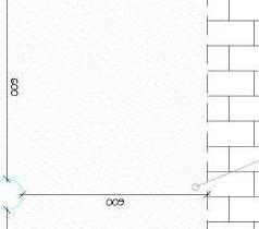
UP3 BR-103 Formation level of mass concrete trench to be min. 1.25m below existing ground level or 600mm below lowest live tree root, whichever is the deeper depending upon B.C. O.2 BR-103 1831 1662 6125 8621 3060 553 5573 3060 6513 450 791 1771 51395420 3093 3 BR-103 Extract fan min 30l/s placed above hob. HD ** L Steel plate lintel for Bay Window L Concrete lintel MH Proposed Manhole Catnic lintel CG90/125 Cavity wall lintel Extract fan min 15l/s. FF L L Catnic lintel CG90/125 Cavity wall lintel L Catnic lintel CG90/125 Cavity wall lintel SD HD ** 15.7 m² SITTING ROOM 16.1 m² GARDEN ROOM 80.3 m² PRIVATE GARDEN 80.3 m² PRIVATE GARDEN 19.5 m² KITCHEN DINING2 BR-103 Proposed SVP Rodding point to be installed to the pipe Inspection Chamber Rodding point to be installed to the pipe MH GF-01 GF-02 GF-03 GF-04 GF-05 GF 01 TOBE BOLTED DOWN TO GF-02 & GF-03 WITH 2 NO, M12 BOLTS EACH END. 8mm MS PLATE TO BE WELDED TO THE UNDERSIDE TO CARRY THE EXTERNAL BRICK LEAF Structural Load Bearing Wall GF-05 RAIN WATER PIPE RAIN WATER PIPE Written dimensions to be taken in preferences to scaled dimensions. The Contractor is responsible for checking all dimensions before work starts. All work is to be carried out to the requirements, and to the satisfaction of the Local Authority. These drawings are for planning purposes only. Dimensions Local Authority Rev Date Description Made Checked Drawing Status: FOR APPROVAL Client Project Drawing Title Drawn/Design Scales: AS SHOWN @ A1 Drawing No Date Rev RPR PLANNING Office 5, 37 Stanmore Hill London, HA7 3DS. Tel: Mobile: Web: Email: 078 9661 7854 www. rprplanning.co.uk info@rprplanning.co.uk 25/09/2023 09:57:38 AM C:\Users\saada\Desktop\RPR PLANNING\99 ORCHARD GATE \2023.06.2399 Orchard GateBuilding Regulation .rvt99 Orchard Gate, Greenford UB6 0QN STRUCTURE - PROPOSED FOUNDATION & GROUND FLOOR PLANS 05/02/23 BR-104 SCALE: 1 100 @ A3 1 50 @ A1 STRUCTURE -Foundations SCALE: 1 100 @ A3 1 50 @ A1 STRUCTURE -Proposed ground floor SD Span direction KEY New wall Existing walls to be removed Existing wall to be retained ** FD30 Fire doors -refer to fire precautions notes. Smoke Detector position -refer to fire precautions notes. FD30s SC (30 minute 44mm solid fire door with smoke seal in the fire frame and be fitted with a self-closing device) HD Heat Detector position -refer to fire precautions notes. VISUAL SCALE 1:50 @ A1 5m 1m 4m 3m 2m 0m 1:100 @ A3 STEEL DETAILS: Beam: RB01 Use 152 x 152 x 37 UC S275 Beam: RB02 Use 178 x 102 x 19 UB S275 Bearing R1: 8 mm m.s. bearing plate, size 200 x 100 mm Bearing R2: As R1 Beam: RB03 Use 178 x 102 x 19 UB S275 Bearing R1: 8 mm m.s. bearing plate, size 200 x 100 mm Bearing R2:
STRUCTURE -Proposed Loft
Beam: LF01
Use 152 x 152 x 23 UC S275
Bearing R1: 8 mm m.s. bearing plate, size 200 x 100 mm
Bearing R2: As R1
Beam: LF02
Use 203 x 203 x 46 UC S275
Bearing R1: 25 mm m.s. bearing plate, size 450 x 100 mm
Bearing R2: As R1
Beam: LF03
Use 152 x 152 x 37 UC S275
Bearing R1: 20 mm m.s. bearing plate, size 400 x 100 mm
Bearing R2: 20 mm m.s. bearing plate, size 400 x 100 mm
Beam: LF04
Use 203 x 203 x 46 UC S275
Bearing R1: 25 mm m.s. bearing plate, size 450 x 100 mm
Bearing R2: As R1
T1 Use C24 47mm x 145mm Floor joist
R2 USE C24 38mm x170mm Ceiling joist
R0 USE C24 47mm x150mm Ceiling joist
x 89 x 16 UB S275
Bearing R1: 10 mm m.s. bearing plate, size 300 x 100 mm
Bearing R2: As R1
Sections to be bolted together with tube spacers or suitable alternative connection at max 1.5m c/s
Beam: GF03
Use 152 x 89 x 16 UB S275
Bearing R1: 8 mm m.s. bearing plate, size 200 x 100 mm
Bearing R2: As R1
Beam: GF04
Use 178 x 102 x 19 UB S275
Bearing R1: 8 mm m.s. bearing plate, size 200 x 100 mm
Bearing R2: As R1
Beam: GF05
Use 203 x 203 x 46 UC S275
Bearing R1: 25 mm m.s. bearing plate, size 500 x 100 mm
Bearing R2: As R1 8mm ms plate welded to the underside to carry the external brick leaf.
DN UP DN3 BR-103 7.4 m² BEDROOM 3 14.1 m² BEDROOM 2 11.8 m² BEDROOM 1 3.4 m² HALL 3.9 m² BATHROOM ** SD L Catnic lintel CG90/125 Cavity wall lintel Proposed SVP All the structure shown in on the floor TR02 T1 T12 BR-103 ** ** ** LF-01 LF-02 LF-03 LF-04 L Catnic lintel CG90/125 Cavity wall lintel L Bearing Plate Bearing Plate 20 mm m.s. bearing plate, size 400 x 100 mm 25 mm m.s. bearing plate, size 450 x 100 mm L L T1 T13 BR-103 4.3 m² EN-SUITE 30.7 m² BEDROOM ** SD Extract fan min 15l/s. All the structure shown in on the floor TR02 T1 T12 BR-103 RB-01 RB-03 RB-02 RB-01 TO BE BOLTED TO RB-02 AND RB-03 EACH END WITH 2NO. H12 BOLTS TR01 Written dimensions to be taken in preferences to scaled dimensions. The Contractor is responsible for checking all dimensions before work starts. All work is to be carried out to the requirements, and to the satisfaction of the Local Authority. These drawings are for planning purposes only. Dimensions Local Authority Rev Date Description Made Checked Drawing Status: FOR APPROVAL Client Project Drawing Title Drawn/Design Scales: AS SHOWN @ A1 Drawing No Date Rev RPR PLANNING Office 5, 37 Stanmore Hill London, HA7 3DS. Tel: Mobile: Web: Email: 078 9661 7854 www. rprplanning.co.uk info@rprplanning.co.uk 25/09/2023 09:57:40 AM C:\Users\saada\Desktop\RPR PLANNING\99 ORCHARD GATE \2023.06.2399 Orchard GateBuilding Regulation .rvt99 Orchard Gate, Greenford UB6 0QN STRUCTURE - PROPOSED FIRST LOFT & ROOF PLAN 05/02/23 BR-105 VISUAL SCALE 1:200 @ A1 20m 4m 16m 12m 8m 0m 1:400 @ A3 VISUAL SCALE 1:50 @ A1 5m 1m 4m 3m 2m 0m 1:100 @ A3 SCALE: 1 : 100 @ A3 1 : 50 @ A1 STRUCTURE -Proposed first floor SCALE: 1 100 @ A3 1 50 @ A1
STEEL DETAILS: Beam: RB01 Use 152 x 152 x 37 UC S275 Beam: RB02 Use 178 x 102 x 19 UB S275 Bearing R1: 8 mm m.s. bearing plate, size 200 x 100 mm Bearing R2: As R1 Beam: RB03 Use 178 x 102 x 19 UB S275 Bearing R1: 8 mm m.s. bearing plate, size 200 x 100 mm Bearing R2: As R1 Beam: GF01 Use 178 x 102 x 19 UB S275 Beam: GF02 Use 2No 152
Use 6x2 Roof Trimmer Double up roof joists to roof light joist to be bolted together with timber connectors and M10 (4.6) bolts @ 600mm staggered centers using oversized washers.
Pitched roof rafter (R2) -Use 50x150 -C24 @ 400mm c/c
Double up roof joists to roof light joist to be bolted together with timber connectors and M10 (4.6) bolts @ 600mm staggered centers using oversized washers.
Double up floor joists under partitions running parallel with the floor, and use solid noggins between joists when partitions run perpendicular to floor span direction. Use 100mm thick Celotex GA4000 insulation placed between joists, supported by 25mm wide x 38mm dp battens fixed onto joists. Use 500 micron flexible polyethylene to wrap the edges of joists.
Beam: RB03
178 x 102 x 19 UB S275 Bearing R1: 8 mm m.s. bearing plate, size 200 x 100 mm
Bearing R2: As R1
Beam: LF01 Use 152 x 152 x 23 UC S275
Bearing R1: 8 mm m.s. bearing plate, size 200 x 100 mm
Bearing R2: As R1
Beam: LF02
Use 203 x 203 x 46 UC S275
Bearing R1: 25 mm m.s. bearing plate, size 450 x 100 mm
Bearing R2: As R1
Beam: LF03


Use 152 x 152 x 37 UC S275
Bearing R1: 20 mm m.s. bearing plate, size 400 x 100 mm
Bearing R2: 20 mm m.s. bearing plate, size 400 x 100 mm
Beam: LF04
Use 203 x 203 x 46 UC S275
Bearing R1: 25 mm m.s. bearing plate, size 450 x 100 mm
Bearing R2: As R1
T1 Use C24 47mm x 145mm Floor joist

R2 USE C24 38mm x170mm Ceiling joist

R0 USE C24 47mm x150mm Ceiling joist
Bearing R2: As R1 Sections to be bolted together with tube spacers or suitable alternative connection at max 1.5m c/s
Beam: GF03
152 x 89 x 16 UB S275
Bearing R1: 8 mm m.s. bearing plate, size 200 x 100 mm
Bearing R2: As R1
Beam: GF04
Use 178 x 102 x 19 UB S275

Bearing R1: 8 mm m.s. bearing plate, size 200 x 100 mm
Bearing R2: As R1
Beam: GF05
Use 203 x 203 x 46 UC S275
Bearing R1: 25 mm m.s. bearing plate, size 500 x 100 mm
Bearing R2: As R1
8mm ms plate welded to the underside to carry the external brick leaf.
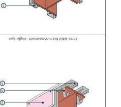
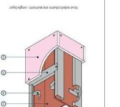
3 BR-1032 BR-103 VELUX PK08 R0 VELUX PK08 R2 ROOFDRAIN PIPE ROOFDRAIN PIPE PROPOSED SVP 30 MINUTES FIRE RESISTANCE TO BEAMS AND COLUMNS DETAILS Written dimensions to be taken in preferences to scaled dimensions. The Contractor is responsible for checking all dimensions before work starts. All work is to be carried out to the requirements, and to the satisfaction of the Local Authority. These drawings are for planning purposes only. Dimensions Local Authority Rev Date Description Made Checked Drawing Status: FOR APPROVAL Client Project Drawing Title Drawn/Design Scales: AS SHOWN @ A1 Drawing No Date Rev RPR PLANNING Office 5, 37 Stanmore Hill London, HA7 3DS. Tel: Mobile: Web: Email: 078 9661 7854 www. rprplanning.co.uk info@rprplanning.co.uk 25/09/2023 09:57:42 AM C:\Users\saada\Desktop\RPR PLANNING\99 ORCHARD GATE \2023.06.2399 Orchard GateBuilding Regulation .rvt99 Orchard Gate, Greenford UB6 0QN STRUCTURE - PROPOSED ROOF PLAN 05/02/23 BR-106 VISUAL SCALE 1:200 @ A1 20m 4m 16m 12m 8m 0m 1:400 @ A3 VISUAL SCALE 1:50 @ A1 5m 1m 4m 3m 2m 0m 1:100 @ A3 SCALE: 1 : 100 @ A3 1 50 @ A1 STRUCTURE -Proposed Roof SCALE: 1 20 @ A3 1 2 @ A1 DETAIL -30 Minutes fire resistance columns and beams STEEL DETAILS: Beam: RB01 Use 152 x 152 x 37 UC S275 Beam: RB02 Use 178 x 102 x 19 UB S275 Bearing R1: 8 mm m.s. bearing plate, size 200 x 100 mm Bearing R2: As R1
Use
Use
Use
Beam: GF01
178 x 102 x 19 UB S275 Beam: GF02
2No 152 x 89 x 16 UB S275 Bearing R1: 10 mm m.s. bearing plate, size 300 x 100 mm
Use
consolidated well-rammed


Blinded with 50mm sand blinding.

of 150mm consolidated well-rammed hardcore. Blinded with 50mm sand blinding. Provide ground bearing slab to Structural Eng. spec over a 1200 gauge polythene DPM. DPM to be lapped in with DPC in walls. Floor to be insulated over slab and DPM with min 140mm thick CELOTEX XR4140 insulation to continue around floor perimeters to avoid thermal bridging. A VCL should be laid over the insulation boards and turned up 100mm at room perimeters behind the skirting, all joints to be lapped 150mm and sealed. Finish with 65mm sand/cement finishing screed with light mesh reinforcement. Where drain runs pass under new floor, provide A142 mesh 1.0m wide and min 50mm concrete cover over length of drain. Where existing suspended timber floor air bricks are covered by new extension, ensure cross-ventilation is maintained by connecting to 100mm dia UPVC pipes with 100mm concrete cover laid under the extension. Pipes to terminate at new 65mm x 215mm air bricks with cavity tray over.
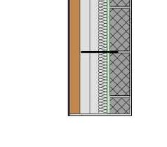
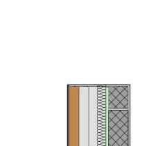
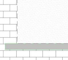

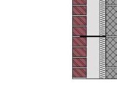
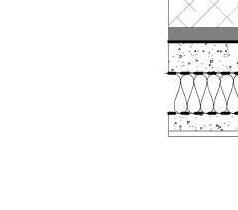
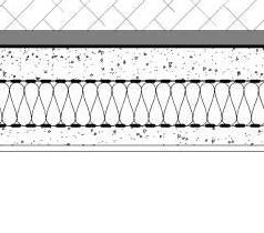
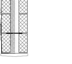
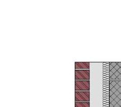
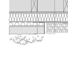
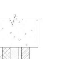
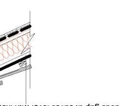
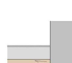
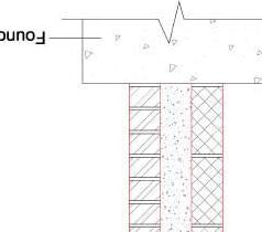
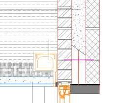
Partial fill Cavity Insulation CW4000 (45mm thk) or similar to achieve max 0.18 W/m²k 100mm thick Thermalite Hi Strength blockwork, on a class (iii) (M4) mortar, compressive strength as indicated by Structural Engineer 102.5mm thick facing brickwork 100mm thick Thermalite Hi Strength blockwork, on a class (iii) (M4) mortar, compressive strength as indicated by Structural Engineer 353 13 100 140 100 INTERIOR EXTERIOR 150 150 Tiles hung vertically on 25 x 38mm preservative treated battens 12mm thick W.B.P external quality plywood sheathing Treated timber frame studs constructed using: 150mm 50mm head and sole plates and vertical studs (with noggins) at 400mm centres or to structural engineer's details and calculations. 100mm Kingspan Thermawall TW55 between 22mm Gyproc Thermaline Basic over with VCL fixed to internal face of insulation Finish with 3mm skim coat of finishing plaster. Single layer 12.5mm plasterboard and skim. Joints taped and staggered DORMER WALL 12.5mm plasterboard and skim. Joints taped and staggered 12.5mm plasterboard and skim. Joints taped and staggered INSIDE OUTSIDE INSIDEINSIDE CAVITY WALL NEW DWELLING BLOCK WALL 47 x 75mm vertical studs at 400mm c/c with cross noggins 12.5mm plasterboard and skim. Joints taped and staggered wall cavities to be filled with 75mm ROCKWOOL STUD WALL 100mm 400 100 INSIDEINSIDE Wall ties, approved Document E, Tie type A INSIDE OUTSIDE Partial fill Cavity Insulation CW4000 (45mm thk) or similar to achieve max 0.18 W/m²k Timber Boarding 12.5mm plasterboard and skim. Joints taped and staggered Wall ties, approved Document E, Tie type A External Zinc standing seam system CAVITY WALL 320 100 Damp Control Course Air Ventilation cavity 227 86 100 20040 491 ENGINEERED SOIL WITH PLANTINGS FILTER FABRIC RESERVOIR LAYER MOISTURE-RETENTION LAYER UNDER LAYER THERMAL INSULATION VAPOUR CONTROL LAYER STRUCTURAL DECK, PRIME AS REQUIRED CEILING FINISHING RETENTION TRIM PARAPET WALL SEPARATING GRAVEL EDGE FILTER FLENCE REINFORCED STRAP CAP SHEET Partial fill Cavity Insulation CW4000 (90mm thk) or similar to achieve max 0.18 W/m²k Thermalite Hi Strength blockwork, on a class (iii) (M4) mortar, compressive strength as indicated by Structural Engineer Eng. B Brickwork in class (ii) mortar up to 150mm above proposed ground level Ground level Damp-proof course Mass concrete foundation taken down to good ground, Formation level of mass concrete trench to be min. 1.25m below existing ground level or 600mm below lowest live tree root, whichever is the deeper depending upon B.C. O. SOLID FLOOR INSULATION OVER SLAB To meet min U value required of 0.13W/m²K Solid ground floor to consist
150mm
140mm
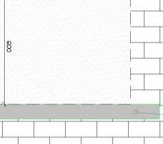
65mm concrete sand cement screed with light reinforcement DPC 150mm above ground level lapped to DPM Concrete slab to Structural Eng. Spec 1200g damp proof membrane A VCL should be laid over and under the insulation Foundation to Structural Eng. Spec Engineering Brick Written dimensions to be taken in preferences to scaled dimensions. The Contractor is responsible for checking all dimensions before work starts. All work is to be carried out to the requirements, and to the satisfaction of the Local Authority. These drawings are for planning purposes only. Dimensions Local Authority Rev Date Description Made Checked Drawing Status: FOR APPROVAL Client Project Drawing Title Drawn/Design Scales: AS SHOWN @ A1 Drawing No Date Rev RPR PLANNING Office 5, 37 Stanmore Hill London, HA7 3DS. Tel: Mobile: Web: Email: 078 9661 7854 www. rprplanning.co.uk info@rprplanning.co.uk 25/09/2023 09:57:45 AM C:\Users\saada\Desktop\RPR PLANNING\99 ORCHARD GATE \2023.06.2399 Orchard GateBuilding Regulation .rvt99 Orchard Gate, Greenford UB6 0QN TYPICAL DETAILS 05/02/23 BR-107 VISUAL SCALE 1:10 @ A1 1m 0.2m 0.8m 0.6m 0.4m 0m 1:20 @ A3 SCALE: 1 20 @ A3 1 10 @ A1 DETAIL -Types of wall SCALE: 1 : 20 @ A3 1 : 10 @ A1 DETAIL -Typical drainage through new wall -600mm SCALE: 1 20 @ A3 1 10 @ A1 DETAIL -Green Roof with parapet SCALE: 1 20 @ A3 1 10 @ A1 DETAIL -Cavity wall -Solid ground floor New Dwelling
hardcore.
thick CELOTEX XR4140


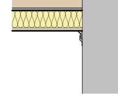


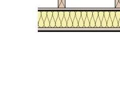

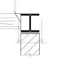


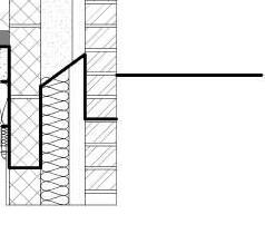
WARM FLAT ROOF To achieve U value 0.18 W/m²K To Structural Engineer's details. Flat roof to be single ply membrane roofing providing aa fire rating for surface spread of flame with a current BBA or WIMLAS Certificate and laid to specialist specification. Single ply membrane to be fixed to 22mm exterior quality plywood over 125mm Kingspan Thermaroof TR27 /FM LPC Insulation bonded to 22mm external quality plywood decking or similar approved on sw firings to minimum 1 in 80 fall on C24 flat roof joists as per Structural Engineer's details and calculations. Underside of joists to have 12.5mm foil backed plasterboard and skim. Interior Interior Exterior Existing wall Roof decking, OSB3 Oriented Strand Board Tongue & Groove - 2.4m x 590mm x 18mm Structural joists, as detail. 12.5mm foil backed plasterboard and skim. Continue foil vapor control layer. Single ply membrane to be fixed to 22mm exterior quality plywood. Slope 1:80 Lead flashing. Timber fillet. 125mm Kingspan Thermaroof TR27 /FM LPC. Interior Exterior Allow for 100mm ferrings 18 PITCHED ROOF CONSTRUCTION Tiles type and colour to match the existing on 25 x 38mm SW battens on TYVEK SUPRO fully breathable roofing felt on timber as specified by Structural Engineer - refer to drawings. Pitched roof (sloping roof) to be insulated, provide 100mm thick CELOTEX GA4000 insulation between rafters and 50mm fixed underneath rafters. Fix polythene (1000 gauge), vapour control layer including air leakage (permable underlay) barrier with 2x12.5mm plasterboard with 3mm plaster skim Achieves 0.11W/m²K. Temporary works required shown indicatively. Temporary works design by contractor Existing timber floor joists Joist hanger 3:1 sand/cement dry pack to be installed to ensure tight fit between beam and wall over Written dimensions to be taken in preferences to scaled dimensions. The Contractor is responsible for checking all dimensions before work starts. All work is to be carried out to the requirements, and to the satisfaction of the Local Authority. These drawings are for planning purposes only. Dimensions Local Authority Rev Date Description Made Checked Drawing Status: FOR APPROVAL Client Project Drawing Title Drawn/Design Scales: AS SHOWN @ A1 Drawing No Date Rev RPR PLANNING Office 5, 37 Stanmore Hill London, HA7 3DS. Tel: Mobile: Web: Email: 078 9661 7854 www. rprplanning.co.uk info@rprplanning.co.uk 25/09/2023 09:57:47 AM C:\Users\saada\Desktop\RPR PLANNING\99 ORCHARD GATE \2023.06.2399 Orchard GateBuilding Regulation .rvt99 Orchard Gate, Greenford UB6 0QN TYPICAL DETAILS 05/02/23 BR-108 SCALE: 1 20 @ A3 1 10 @ A1 DETAIL -Warm flat roof SCALE: 1 20 @ A3 1 10 @ A1 DETAIL -Exterior slab SCALE: 1 20 @ A3 1 10 @ A1 DETAIL -Pitch roof-Ceiling New Dwelling SCALE: 1 20 @ A3 1 10 @ A1 DETAIL -Typical Steel Beam installation

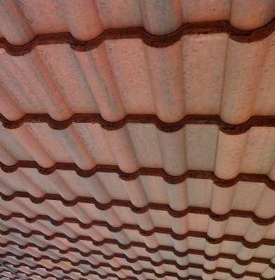
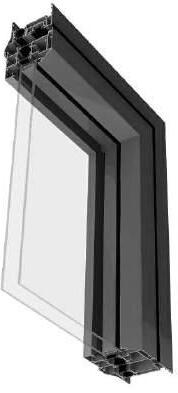
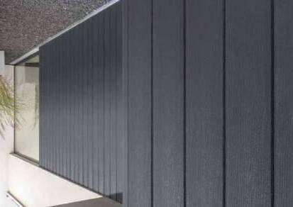

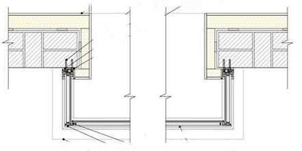
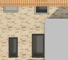
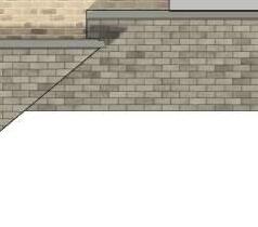
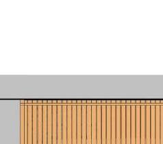
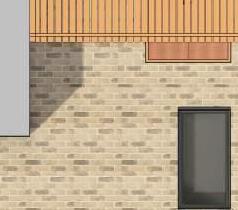
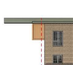
Written dimensions to be taken in preferences to scaled dimensions. The Contractor is responsible for checking all dimensions before work starts. All work is to be carried out to the requirements, and to the satisfaction of the Local Authority. These drawings are for planning purposes only. Dimensions Local Authority Rev Date Description Made Checked Drawing Status: FOR APPROVAL Client Project Drawing Title Drawn/Design Scales: AS SHOWN @ A1 Drawing No Date Rev RPR PLANNING Office 5, 37 Stanmore Hill London, HA7 3DS. Tel: Mobile: Web: Email: 078 9661 7854 www. rprplanning.co.uk info@rprplanning.co.uk 25/09/2023 09:57:48 AM C:\Users\saada\Desktop\RPR PLANNING\99 ORCHARD GATE \2023.06.2399 Orchard GateBuilding Regulation .rvt99 Orchard Gate, Greenford UB6 0QN MATERIAL DETAILS 05/02/23 BR-109 VISUAL SCALE 1:200 @ A1 20m 4m 16m 12m 8m 0m 1:400 @ A3 SD Span direction KEY New wall Existing walls to be removed Existing wall to be retained FD30 Fire doors -refer to fire precautions notes. Smoke Detector position -refer to fire precautions notes. FD30s SC (30 minute 44mm solid fire door with smoke seal in the fire frame and be fitted with a self-closing device) VISUAL SCALE 1:50 @ A1 5m 1m 4m 3m 2m 0m 1:100 @ A3 HD Heat Detector position -refer to fire precautions notes. 200 mm Soffit in Black Finish WINDOW BAND AND CONCRETE SILL Concrete Sill Detail Plastered Window band 50mm thick and 25mm deep Aluminium Window Profile in Black Finish Composite External Wall Cladding in Garden Room Composite Wall Cladding in Light Grey Finish Front bay Window Rosemary Clay Tile Cladding Matching With Existing Street Finsih Soffit Detail Clay Roof Tile Cladding Matching With Existing Street Finsih Red Brick Finsish on External Wall matching with Existing neighbour walls PPC Aluminium Bonding Flashing 90 corner Detail withblack Bond to interior face Black low modulus Silicone Typical Existing brick wall with insulation, thickness to Suit Uvalue Requirement Fixing to suit Structure Structure to be approved by structural engineer and window manufacturer EDPM Invisio Glass Up and over Glass System Garden Room Oriel Box Wndow Anthracite Grey UPVC Cladding Exterior Vertical


180300 180300 516200 516200 01020 24.9m 24.7m CR B oCon &WadBdy CHIGNELL PLACE WALS I NGHAM ROAD CANBERRAROAD 1 ot 5 21 01 11 2 711 921 O ce 931 G ov rn ent 146 128 22 13 PH 134 1 131 731 15 PH St James's Church 141 126 o 136 13 o 140 5 144 1 5 156 1 2 c931 TCB TCBs LB TCB Sun s S nse N N Written dimensions to be taken in preferences to scaled dimensions. The Contractor is responsible for checking all dimensions before work starts. All work is to be carried out to the requirements, and to the satisfaction of the Local Authority. These drawings are for planning purposes only. Dimensions Local Authority Rev Date Description Made Checked Drawing Status: FOR APPROVAL Client Project Drawing Title Drawn/Design Scales: AS SHOWN @ A1 Drawing No Date Rev RPR PLANNING Office 5, 37 Stanmore Hill London, HA7 3DS. Tel: Mobile: Web: Email: 078 9661 7854 www. rprplanning.co.uk info@rprplanning.co.uk- 19/09/2023 10:41:33 AM C:\Users\saada\Desktop\RPR PLANNING\127 Broadway\20 23.07.05127 BroadwayPlanning.rvt127 Broadway, London W13 9BE OS MAP, BLOCK PLAN 10/05/23 PL-100 SCALE: 1 400 @ A3 1 200 @ A1 PL -Block Plan SCALE: 1:2500 @ A3 1 1250 @ A1 PL -OS MAP VISUAL SCALE 1:50 @ A1 5m 1m 4m 3m 2m 0m 1:100 @ A3 VISUAL SCALE 1:200 @ A1 20m 4m 16m 12m 8m 0m 1:400 @ A3 VISUAL SCALE 1:1250 @ A1 125m 25m 100m 75m 50m 0m 1:2500 @ A3
UP UP BOUNDARY BOUNDARY 1 PL-108 5543 1078 5760 844 1334 930 3394 2093 987 2351 759 2188 1951 2805 4853 6247 1343 1334 2.3 m² WC 7.1 m² OFFICE 7.6 m² STORAGE 6.6 m² HALL 71.0 m² CASINO 1334 646 2440 6820 No.129 No.125 363 5426 FLAT ENTRANCE STUDIO FLAT SLEEPING AREA SHOP STORAGE BOUNDARY BOUNDARY 2 PL-108 No.129 No.125 3.7 m² BIKES AND BINS STORAGE FLAT 4 62.9 m² CASINO 10.5 m² HALL 25.2 m² KITCHEN LIVING DINING 2.3 m² HALL 5.0 m² OUTDOOR AMENITY 16.1 m² LIGHTWELL STUDIO 1P Flat 1 37.9m2 FLAT 1 FLAT 4 1200 7.5 m² SLEEPING AREA FF 3.1 m² BATHROOM BINS STORAGE FLAT 1 & 2 BIKE STORAGE FLAT 1, 2 & 3 BINS STORAGE FLAT 3 FLAT 3 FLAT ENTRANCE STUDIO FLAT SLEEPING AREA SHOP STORAGE 3430 1100 2300 810 1800 900 1.6 m² WC 1973 1.7 m² TOILET 1.7 m² TOILET 2.5 m² EN-SUITE 7.6 m² OFFICE 3250 COUNTER 2250 900 CPB FLAT 2 STUDIO 1P Flat 2 37.6m2 FF 705 1350 2330 1.3 m² STORE 1100 2150 ? ? 10.9 m² STUDIO FLAT SLEEPING AREA 23.0 m² KITCHEN LIVING DINING 0.9 m² STORE 1000 2092 FLAT 1 STUDIO 1P 37.9m2 FLAT 2 2B3P 66m2 FLAT 3 2B3P 81m2 FLAT REFERENCES FLAT 2 STUDIO 1P 37.6m2 Written dimensions to be taken in preferences to scaled dimensions. The Contractor is responsible for checking all dimensions before work starts. All work is to be carried out to the requirements, and to the satisfaction of the Local Authority. These drawings are for planning purposes only. Dimensions Local Authority Rev Date Description Made Checked Drawing Status: FOR APPROVAL Client Project Drawing Title Drawn/Design Scales: AS SHOWN @ A1 Drawing No Date Rev RPR PLANNING Office 5, 37 Stanmore Hill London, HA7 3DS. Tel: Mobile: Web: Email: 078 9661 7854 www. rprplanning.co.uk info@rprplanning.co.uk- 19/09/2023 10:41:33 AM C:\Users\saada\Desktop\RPR PLANNING\127 Broadway\20 23.07.05127 BroadwayPlanning.rvt127 Broadway, London W13 9BE EXISTING AND PROPOSED GROUND FLOOR PLAN 05/12/23 PL-101 VISUAL SCALE 1:50 @ A1 5m 1m 4m 3m 2m 0m 1:100 @ A3 SCALE: 1 100 @ A3 1 50 @ A1 PL -Existing ground floor SCALE: 1 100 @ A3 1 50 @ A1 PL -Proposed ground floor
DN DN DN DN BOUNDARY BOUNDARY 1 PL-108 5305 7426 1892 3633 4753 2523 4814 1882 866 3205 1902 4.8 m² KITCHEN 15.0 m² ROOM 27.0 m² OFFICE 2944 516 1112 2023 1377 1937 268 512 3840 6820 No.129 No.125 4500° 0.8 m² WC STORAGE BATHROOM LIVING DINING HALL LIVING DINING BOUNDARY BOUNDARY 2 PL-108 No.129 No.125 4500° 25.0 m² KITCHEN LIVING/ DINING 890 FLAT 3 2B3P 66m2 4.1 m² BATHROOM 15.0 m² BEDROOM 1 3.9 m² HALL 1.5 m² WC 7.5 m² BEDROOM 2 353 5.2 m² TERRACE FLAT 3 FLAT 4 2B3P 81m2 1.0 m² STORAGE 5.2 m² TERRACE 7.5 m² BEDROOM 2623 FF 7.6 m² HALL 2.3 m² HALL LIVING DINING STORAGE BATHROOM HALL LIVING DINING 24.6 m² KITCHEN LIVING DINING FF 0.7 m² STORE FLAT 1 STUDIO 1P 37.9m2 FLAT 2 2B3P 66m2 FLAT 3 2B3P 81m2 FLAT REFERENCES FLAT 2 STUDIO 1P 37.6m2 Written dimensions to be taken in preferences to scaled dimensions. The Contractor is responsible for checking all dimensions before work starts. All work is to be carried out to the requirements, and to the satisfaction of the Local Authority. These drawings are for planning purposes only. Dimensions Local Authority Rev Date Description Made Checked Drawing Status: FOR APPROVAL Client Project Drawing Title Drawn/Design Scales: AS SHOWN @ A1 Drawing No Date Rev RPR PLANNING Office 5, 37 Stanmore Hill London, HA7 3DS. Tel: Mobile: Web: Email: 078 9661 7854 www. rprplanning.co.uk info@rprplanning.co.uk- 19/09/2023 10:41:34 AM C:\Users\saada\Desktop\RPR PLANNING\127 Broadway\20 23.07.05127 BroadwayPlanning.rvt127 Broadway, London W13 9BE EXISTING AND PROPOSED FIRST FLOOR PLAN 11/22/21 PL-102 VISUAL SCALE 1:50 @ A1 5m 1m 4m 3m 2m 0m 1:100 @ A3 SCALE: 1 100 @ A3 1 50 @ A1 PL -Existing first floor SCALE: 1 100 @ A3 1 50 @ A1 PL -Proposed first floor
BOUNDARY BOUNDARY PL-108 No.129 No.125 BOUNDARY BOUNDARY 2 PL-108 No.129 No.125 500 1330 800 3.7 m² BATHROOM 2095 5263 1.5m h 0.7 m² HALL 2588 1700 800 20.3 m² BEDROOM FLAT 1 STUDIO 1P 37.9m2 FLAT 2 2B3P 66m2 FLAT 3 2B3P 81m2 FLAT REFERENCES FLAT 2 STUDIO 1P 37.6m2 Written dimensions to be taken in preferences to scaled dimensions. The Contractor is responsible for checking all dimensions before work starts. All work is to be carried out to the requirements, and to the satisfaction of the Local Authority. These drawings are for planning purposes only. Dimensions Local Authority Rev Date Description Made Checked Drawing Status: FOR APPROVAL Client Project Drawing Title Drawn/Design Scales: AS SHOWN @ A1 Drawing No Date Rev RPR PLANNING Office 5, 37 Stanmore Hill London, HA7 3DS. Tel: Mobile: Web: Email: 078 9661 7854 www. rprplanning.co.uk info@rprplanning.co.uk- 19/09/2023 10:41:35 AM C:\Users\saada\Desktop\RPR PLANNING\127 Broadway\20 23.07.05127 BroadwayPlanning.rvt127 Broadway, London W13 9BE EXISTING AND PROPOSED LOFT PLAN 11/22/21 PL-103 VISUAL SCALE 1:50 @ A1 5m 1m 4m 3m 2m 0m 1:100 @ A3 SCALE: 1 100 @ A3 1 50 @ A1 PL -Existing Loft SCALE: 1 100 @ A3 1 50 @ A1 PL -Proposed Loft Obscure glass window
BOUNDARY BOUNDARY 2 PL-108 GREEN ROOF GREEN ROOF BOUNDARY BOUNDARY 1 PL-108 Written dimensions to be taken in preferences to scaled dimensions. The Contractor is responsible for checking all dimensions before work starts. All work is to be carried out to the requirements, and to the satisfaction of the Local Authority. These drawings are for planning purposes only. Dimensions Local Authority Rev Date Description Made Checked Drawing Status: FOR APPROVAL Client Project Drawing Title Drawn/Design Scales: AS SHOWN @ A1 Drawing No Date Rev RPR PLANNING Office 5, 37 Stanmore Hill London, HA7 3DS. Tel: Mobile: Web: Email: 078 9661 7854 www. rprplanning.co.uk info@rprplanning.co.uk- 19/09/2023 10:41:35 AM C:\Users\saada\Desktop\RPR PLANNING\127 Broadway\20 23.07.05127 BroadwayPlanning.rvt127 Broadway, London W13 9BE EXISTING AND PROPOSED ROOF PLAN 11/22/21 PL-104 VISUAL SCALE 1:50 @ A1 5m 1m 4m 3m 2m 0m 1:100 @ A3 SCALE: 1 100 @ A3 1 50 @ A1 PL -Proposed Roof SCALE: 1 100 @ A3 1 50 @ A1 PL -Existing Roof
Broadway, London W13 9BE EXISTING AND PROPOSED FRONT AND REAR ELEVATIONS


1 PL-108 2 PL-108 Rooflights not to project more than 150mm from the existing roof plane 2 PL-108 Materials to match existing Elevation 1 PL-108 2800 Written dimensions to be taken in preferences to scaled dimensions. The Contractor is responsible for checking all dimensions before work starts. All work is to be carried out to the requirements, and to the satisfaction of the Local Authority. These drawings are for planning purposes only. Dimensions Local Authority Rev Date Description Made Checked Drawing Status: FOR APPROVAL Client Project Drawing Title Drawn/Design Scales: AS SHOWN @ A1 Drawing No Date Rev RPR PLANNING Office 5, 37 Stanmore Hill London, HA7 3DS. Tel: Mobile: Web: Email: 078 9661 7854 www. rprplanning.co.uk info@rprplanning.co.uk- 19/09/2023 10:41:41 AM C:\Users\saada\Desktop\RPR PLANNING\127 Broadway\20 23.07.05127 BroadwayPlanning.rvt127
11/22/21 PL-105 VISUAL SCALE 1:50 @ A1 5m 1m 4m 3m 2m 0m 1:100 @ A3 SCALE: 1 100 @ A3 1 50 @ A1 PL -Existing front elevation SCALE: 1 100 @ A3 1 50 @ A1 PL -Proposed Front elevation SCALE: 1 100 @ A3 1 50 @ A1 PL -Proposed rear elevation SCALE: 1 100 @ A3 1 50 @ A1 PL -Existing rear elevation


No. 125 No. 125 No. 125 No. 125 Obscure glass window Materials to match existing Obscure glass window Written dimensions to be taken in preferences to scaled dimensions. The Contractor is responsible for checking all dimensions before work starts. All work is to be carried out to the requirements, and to the satisfaction of the Local Authority. These drawings are for planning purposes only. Dimensions Local Authority Rev Date Description Made Checked Drawing Status: FOR APPROVAL Client Project Drawing Title Drawn/Design Scales: AS SHOWN @ A1 Drawing No Date Rev RPR PLANNING Office 5, 37 Stanmore Hill London, HA7 3DS. Tel: Mobile: Web: Email: 078 9661 7854 www. rprplanning.co.uk info@rprplanning.co.uk- 19/09/2023 10:41:46 AM C:\Users\saada\Desktop\RPR PLANNING\127 Broadway\20 23.07.05127 BroadwayPlanning.rvt127 Broadway, London W13 9BE EXISTING AND PROPOSED SIDE ELEVATION 05/12/23 PL-106 VISUAL SCALE 1:50 @ A1 5m 1m 4m 3m 2m 0m 1:100 @ A3 SCALE: 1 100 @ A3 1 50 @ A1 PL -Existing side elevation SCALE: 1 100 @ A3 1 50 @ A1 PL -Proposed side elevation


No.129 No.129 No.129 No.129 Written dimensions to be taken in preferences to scaled dimensions. The Contractor is responsible for checking all dimensions before work starts. All work is to be carried out to the requirements, and to the satisfaction of the Local Authority. These drawings are for planning purposes only. Dimensions Local Authority Rev Date Description Made Checked Drawing Status: FOR APPROVAL Client Project Drawing Title Drawn/Design Scales: AS SHOWN @ A1 Drawing No Date Rev RPR PLANNING Office 5, 37 Stanmore Hill London, HA7 3DS. Tel: Mobile: Web: Email: 078 9661 7854 www. rprplanning.co.uk info@rprplanning.co.uk- 19/09/2023 10:41:54 AM C:\Users\saada\Desktop\RPR PLANNING\127 Broadway\20 23.07.05127 BroadwayPlanning.rvt127 Broadway, London W13 9BE EXISTING AND ROPOSED SIDE EELVATION 2 05/12/23 PL-107 SCALE: 1 100 @ A3 1 50 @ A1 PL -Existing side elevation 2 SCALE: 1 100 @ A3 1 50 @ A1 PL -Proposed side elevation 2 VISUAL SCALE 1:50 @ A1 5m 1m 4m 3m 2m 0m 1:100 @ A3
2434 2547 2540 2531 2500 2500 2500 2500 2500 500 5.2 m² TERRACE 25.0 m² KITCHEN LIVING/ DINING 7.6 m² HALL 2.3 m² HALL 15.0 m² BEDROOM 1 1.5 m² WC 7.5 m² BEDROOM 3.4 m² HALL 3.7 m² BATHROOM 2.7 m² HALL 7.5 m² SLEEPING AREA 2.3 m² HALL 10.9 m² STUDIO FLAT SLEEPING AREA 2.5 m² EN-SUITE 3.7 m² BIKES AND BINS STORAGE FLAT 4 62.9 m² CASINO 10.5 m² HALL 3.1 m² BATHROOM FLAT 1 FLAT FLAT 3 FLAT 4 Written dimensions to be taken in preferences to scaled dimensions. The Contractor is responsible for checking all dimensions before work starts. All work is to be carried out to the requirements, and to the satisfaction of the Local Authority. These drawings are for planning purposes only. Dimensions Local Authority Rev Date Description Made Checked Drawing Status: FOR APPROVAL Client Project Drawing Title Drawn/Design Scales: AS SHOWN @ A1 Drawing No Date Rev RPR PLANNING Office 5, 37 Stanmore Hill London, HA7 3DS. Tel: Mobile: Web: Email: 078 9661 7854 www. rprplanning.co.uk info@rprplanning.co.uk- 19/09/2023 10:41:57 AM C:\Users\saada\Desktop\RPR PLANNING\127 Broadway\20 23.07.05127 BroadwayPlanning.rvt127 Broadway, London W13 9BE EXISTING AND PROPOSED SECTION 05/12/23 PL-108 VISUAL SCALE 1:50 @ A1 5m 1m 4m 3m 2m 0m 1:100 @ A3 SCALE: 1 100 @ A3 1 50 @ A1 PL -Existing Section 1 SCALE: 1 100 @ A3 1 50 @ A1 PL -Proposed Section 1


183100 183100 519400 519500 519400 519500 10 3 1 6 m CF Bo r o Con t GL Asly Con & L B Bdy SP MOYNE PLACE R A N S F O R D R O A D 30 71 1 6 1 2 1 o 8 R o d C t 1 S u n r S u N 14300 10075 MOYNE PLACE BORO CONST, GL ASLY CONST & LB BDY N Written dimensions to be taken in preferences to scaled dimensions. The Contractor is responsible for checking all dimensions before work starts. All work is to be carried out to the requirements, and to the satisfaction of the Local Authority. These drawings are for planning purposes only. Dimensions Local Authority Rev Date Description Made Checked Drawing Status: FOR APPROVAL Client Project Drawing Title Drawn/Design Scales: AS SHOWN @ A1 Drawing No Date Rev RPR PLANNING Office 5, 37 Stanmore Hill London, HA7 3DS. Tel: Mobile: Web: Email: 078 9661 7854 www. rprplanning.co.uk info@rprplanning.co.uk- 27/09/2023 12:23:37 PM C:\Users\saada\Desktop\RPR PLANNING\15 Mayone place \2023.06.0815 Moyne Place Planning.rvt15 Moyne Pl, London NW10 7EN OS MAP AND BLOCK PLAN 17/04/23 PL-100 SCALE: 1 400 @ A3 1 200 @ A1 PL -Block Plan SCALE: 1:2500 @ A3 1 1250 @ A1 PL -OS MAP VISUAL SCALE 1:200 @ A1 20m 4m 16m 12m 8m 0m 1:400 @ A3 VISUAL SCALE 1:1250 @ A1 125m 25m 100m 75m 50m 0m 1:2500 @ A3 VISUAL SCALE 1:100 @ A1 10m 2m 8m 6m 4m 0m 1:200 @ A3
UP UP 14 13 12 11 10 8 DN DN 6714 6124 3300 45 00° 9634 20.2 m² DINING 17.9 m² KITCHEN/UTILITY 14.9 m² LOUNGE 1 PL-106 20.1 m² DINING 30 17646 15 45 00 1500 5553 320 2200 320 5553 13.2 m² BEDROOM 6.7 m² HALL 30.2 m² LIVING KITCHEN DINING 1.3 m² STORE 8.0 m² BEDROOM 3 2729 2729 8.5 m² BEDROOM 2 3.9 m² BATHROOM 2750 30.2 m² LIVING KITCHEN DINING 2 PL-106 3220 1800 3600 2300 1250 2.9 m² EN-SUITE 700 700 4.1 m² BATHROOM 7.9 m² BEDROOM 3 8.5 m² BEDROOM 2 13.3 m² BEDROOM 1 2.9 m² EN-SUITE 11.3 m² COMMUNAL HALL EXISTING CROSSOVER 1 1 0 0 L No.4 x car parking spaces to serve all the flats and the existing house Refuse/recycling storage with fence to serve the new flats Secure bike storage to serve flats 1,2, 3 and 4 4000 New hedges and landscape area Permeable paving footpath Grasscrete to car parking area New hedges and landscape area 1.1 m² STORE 4 Obscure windows REAR GARDEN FLAT 1 117.25m REAR GARDEN FLAT 2 118.44m2 1500 3180 Permeable paving driveway Permeable paving footpath 126.6 m² RETAIN GARDEN FOR THE EXISTING HOUSE 905 1215 1.7 m² STORE 6.5 m² HALL 1 1 0 0 L 6893 6893 1250 1210 2735 1750 5495 5493 2723 5553 5553 1215 1419 1419 2750 1500 2895 1400 1800 1200 3.2 m² STORE FLAT 2 3BED 4 PERSON FLAT 1 3BED PERSON 1210 4040 WARDROBE 6000 3600 FF 3667 Obscure windows FLAT 1 3 Bed 4Persons 80.4 m2 FLAT 2 3 Bed 4Persons 79.2 m2 FLAT 3 1 Bed 2Persons 55.7 m2 FLAT REFERENCES FLAT 4 1 Bed 2Persons 53.6 m2 Written dimensions to be taken in preferences to scaled dimensions. The Contractor is responsible for checking all dimensions before work starts. All work is to be carried out to the requirements, and to the satisfaction of the Local Authority. These drawings are for planning purposes only. Dimensions Local Authority Rev Date Description Made Checked Drawing Status: FOR APPROVAL Client Project Drawing Title Drawn/Design Scales: AS SHOWN @ A1 Drawing No Date Rev RPR PLANNING Office 5, 37 Stanmore Hill London, HA7 3DS. Tel: Mobile: Web: Email: 078 9661 7854 www. rprplanning.co.uk info@rprplanning.co.uk- 27/09/2023 12:23:38 PM C:\Users\saada\Desktop\RPR PLANNING\15 Mayone place \2023.06.0815 Moyne Place Planning.rvt15 Moyne Pl, London NW10 7EN EXISTING AND PROPOSED GROUND FLOOR PLAN 11/22/21 PL-101 SCALE: 1:200 @ A3 1 100 @ A1 PL -Existing ground floor SCALE: 1:200 @ A3 1 100 @ A1 PL -Proposed ground floor VISUAL SCALE 1:100 @ A1 10m 2m 8m 6m 4m 0m 1:200 @ A3 WARDROBE WARDROBE WARDROBE WARDROBE WARDROBE
DN DN DN 14 13 12 11 10 98 DN DN 9.6 m² BEDROOM 2 4.8 m² BATHROOM 13.5 m² BEDROOM 1 6.3 m² BEDROOM 3 2 PL-106 26.2 m² KITCHEN LIVING DINING 26.2 m² KITCHEN LIVING DINING 17.2 m² BEDROOM 1 6.3 m² BEDROOM 3 13.5 m² BEDROOM 1 9.6 m² BEDROOM 2 4.8 m² BATHROOM 3.7 m² COMMUNAL HALL 45 00° 360 2750 FF 2655 GREEN ROOF Obscure window 1400 19.4 m² BEDROOM 1 3460 5.3 m² JACK & JILL FF 6911 6911 1920 5.3 m² JACK & JILL 2.9 m² HALL ATTIC ACCESS STORAGE FOR FLAT ACCESS STORAGE 6.0 m² WINTER GARDEN 6.0 m² WINTER GARDEN 4896 6508 3500 Green Roof Covered Cycle Parking FLAT 1BED PERSONS FLAT 4 1BED PERSONS 2.9 m² HALL 1689 860 DW WM DW WM 1920 4896 2750 6372 3240 1864 5542 FLAT 1 3 Bed 4Persons 80.4 m2 FLAT 2 3 Bed 4Persons 79.2 m2 FLAT 3 1 Bed 2Persons 55.7 m2 FLAT REFERENCES FLAT 4 1 Bed 2Persons 53.6 m2 Written dimensions to be taken in preferences to scaled dimensions. The Contractor is responsible for checking all dimensions before work starts. All work is to be carried out to the requirements, and to the satisfaction of the Local Authority. These drawings are for planning purposes only. Dimensions Local Authority Rev Date Description Made Checked Drawing Status: FOR APPROVAL Client Project Drawing Title Drawn/Design Scales: AS SHOWN @ A1 Drawing No Date Rev RPR PLANNING Office 5, 37 Stanmore Hill London, HA7 3DS. Tel: Mobile: Web: Email: 078 9661 7854 www. rprplanning.co.uk info@rprplanning.co.uk- 27/09/2023 12:23:39 PM C:\Users\saada\Desktop\RPR PLANNING\15 Mayone place \2023.06.0815 Moyne Place Planning.rvt15 Moyne Pl, London NW10 7EN EXISTING AND PROPOSED FIRST FLOOR PLAN 11/22/21 PL-102 SCALE: 1 : 100 @ A3 1 100 @ A1 PL -Existing first floor SCALE: 1 100 @ A3 1 100 @ A1 PL -Proposed first floor VISUAL SCALE 1:100 @ A1 10m 2m 8m 6m 4m 0m 1:200 @ A3 WARDROBE WARDROBE
DN 2 PL-106 FLAT 1 3 Bed 4Persons 80.4 m2 FLAT 2 3 Bed 4Persons 79.2 m2 FLAT 3 1 Bed 2Persons 55.7 m2 FLAT REFERENCES FLAT 4 1 Bed 2Persons 53.6 m2 Written dimensions to be taken in preferences to scaled dimensions. The Contractor is responsible for checking all dimensions before work starts. All work is to be carried out to the requirements, and to the satisfaction of the Local Authority. These drawings are for planning purposes only. Dimensions Local Authority Rev Date Description Made Checked Drawing Status: FOR APPROVAL Client Project Drawing Title Drawn/Design Scales: AS SHOWN @ A1 Drawing No Date Rev RPR PLANNING Office 5, 37 Stanmore Hill London, HA7 3DS. Tel: Mobile: Web: Email: 078 9661 7854 www. rprplanning.co.uk info@rprplanning.co.uk- 27/09/2023 12:23:41 PM C:\Users\saada\Desktop\RPR PLANNING\15 Mayone place \2023.06.0815 Moyne Place Planning.rvt15 Moyne Pl, London NW10 7EN EXISTING AND PROPOSED ROOF PLAN 11/22/21 PL-104 SCALE: 1:200 @ A3 1 : 100 @ A1 PL -Proposed Roof SCALE: 1:200 @ A3 1 100 @ A1 PL -Existing Roof VISUAL SCALE 1:100 @ A1 10m 2m 8m 6m 4m 0m 1:200 @ A3


1 PL-106 2180 2 PL-106 1 PL-106 2 PL-106 Obscure windows Obscure windows Written dimensions to be taken in preferences to scaled dimensions. The Contractor is responsible for checking all dimensions before work starts. All work is to be carried out to the requirements, and to the satisfaction of the Local Authority. These drawings are for planning purposes only. Dimensions Local Authority Rev Date Description Made Checked Drawing Status: FOR APPROVAL Client Project Drawing Title Drawn/Design Scales: AS SHOWN @ A1 Drawing No Date Rev RPR PLANNING Office 5, 37 Stanmore Hill London, HA7 3DS. Tel: Mobile: Web: Email: 078 9661 7854 www. rprplanning.co.uk info@rprplanning.co.uk- 27/09/2023 12:24:05 PM C:\Users\saada\Desktop\RPR PLANNING\15 Mayone place \2023.06.0815 Moyne Place Planning.rvt15 Moyne Pl, London NW10 7EN EXISTING AND PROPOSED ELEVATIONS 04/19/23 PL-105 SCALE: 1:200 @ A3 1 : 100 @ A1 PL -Existing front elevation SCALE: 1:200 @ A3 1 : 100 @ A1 PL -Proposed Front elevation SCALE: 1:200 @ A3 1 : 100 @ A1 PL -Existing rear elevation SCALE: 1:200 @ A3 1 : 100 @ A1 PL -Proposed rear elevation VISUAL SCALE 1:100 @ A1 10m 2m 8m 6m 4m 0m 1:200 @ A3 SCALE: 1:200 @ A3 1 : 100 @ A1 PL -Existing side elevation SCALE: 1:200 @ A3 1 100 @ A1 PL -Proposed side elevation SCALE: 1:200 @ A3 1 100 @ A1 PL -Proposed side elevation 2 SCALE: 1:200 @ A3 1 : 100 @ A1 PL -Existing side elevation 2
2510 2425 8.5 m² BEDROOM 2 3.9 m² BATHROOM 30.2 m LIVING KITCHEN DINING 30.2 m² LIVING KITCHEN DINING 2550 26.2 m² KITCHEN LIVING DINING 5.3 m² JACK & JILL 19.4 m² BEDROOM 2550 2525 40.1 m² ATTIC STORE FLAT 3 6.7 m² HALL Written dimensions to be taken in preferences to scaled dimensions. The Contractor is responsible for checking all dimensions before work starts. All work is to be carried out to the requirements, and to the satisfaction of the Local Authority. These drawings are for planning purposes only. Dimensions Local Authority Rev Date Description Made Checked Drawing Status: FOR APPROVAL Client Project Drawing Title Drawn/Design Scales: AS SHOWN @ A1 Drawing No Date Rev RPR PLANNING Office 5, 37 Stanmore Hill London, HA7 3DS. Tel: Mobile: Web: Email: 078 9661 7854 www. rprplanning.co.uk info@rprplanning.co.uk- 27/09/2023 12:25:06 PM C:\Users\saada\Desktop\RPR PLANNING\15 Mayone place \2023.06.0815 Moyne Place Planning.rvt15 Moyne Pl, London NW10 7EN EXISTING AND PROPOSED SECTIONS 04/21/23 PL-106 SCALE: 1:200 @ A3 1 100 @ A1 Existing Section 1 SCALE: 1:200 @ A3 1 100 @ A1 Proposed Section 2 FLAT FLAT