selected works
RYO MIZUKI ARCHITECTURAL DESIGNER
design
architecture +
portfolio
2023
résumé
2
profile
Architectural Designer with 6+ years of experience with focus and passion for modern residential architecture. Approaches projects with attentions to design, as well as importance of construction details. Ryo has great interest in understanding how things are put-together. Experienced in woodworking from a young age, it aided in developing creativity, and forming solutions using various materials and methods.
experience
architectural designer | 2021 - present moss design | chicago, illinois
architectural designer | 2017 - 2021
Senga Architects | chicago, illinois
architectural intern | summer 2016
A.D.O. | tokyo, japan
education
B.S. Architectural Studies, 2013-2017
University of Illinois, Urbana-Champaign
proficiency
Revit
Sketchup
Enscape
Indesign
Photoshop
Hand sketching
3
4
table of contents
01 02 03 04 05 06 07
andersonville residence
single family residence | addition pg 6-11
lakeview residence
single family residence | addition pg 12-17
kildeer residence
second story addition
pg 18-25
adams residence
single family residence | renovation pg 26-29
dance studio
warehouse renovation
pg 30-33
academic + internship
residential projects | model fabrication
pg 34-39
personal projects
woodworking | furniture pg 40-45
5
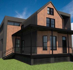
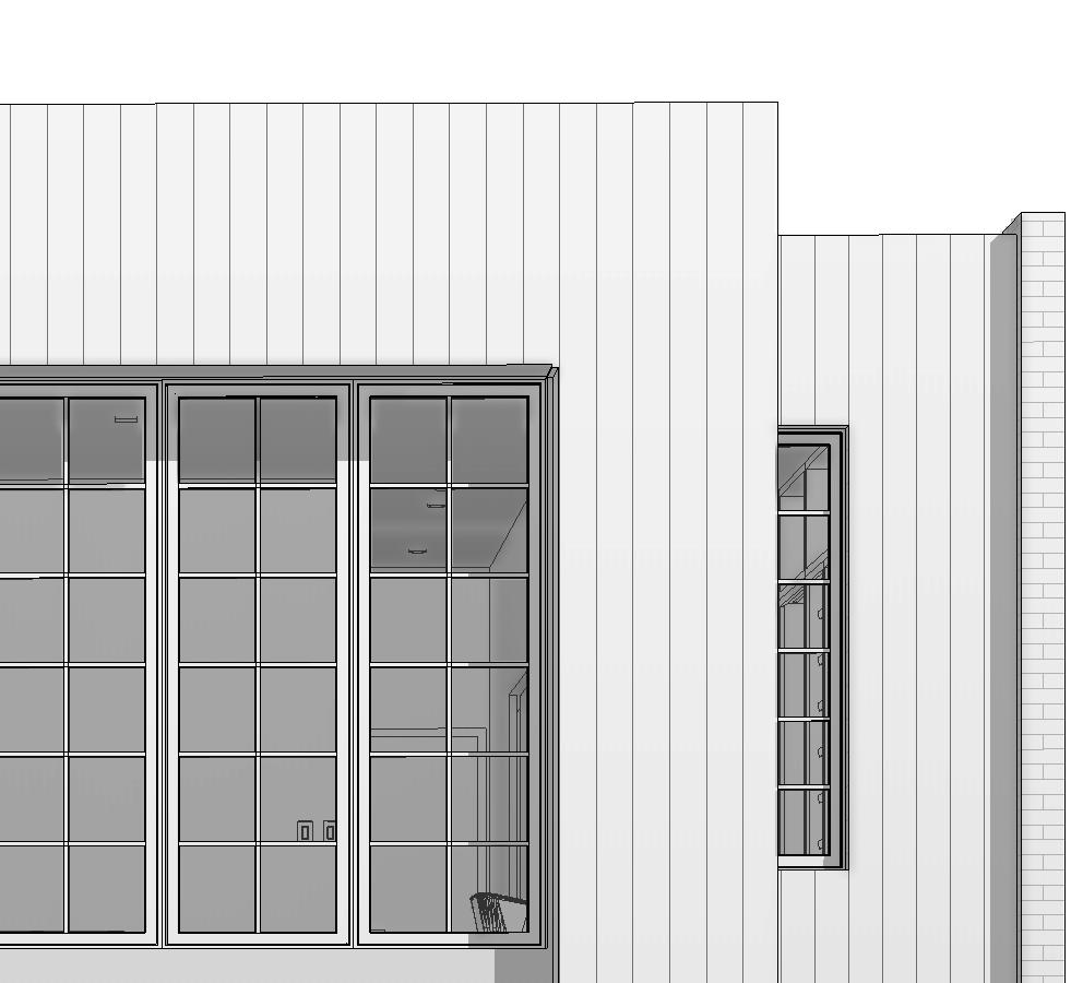
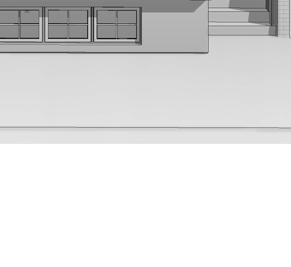
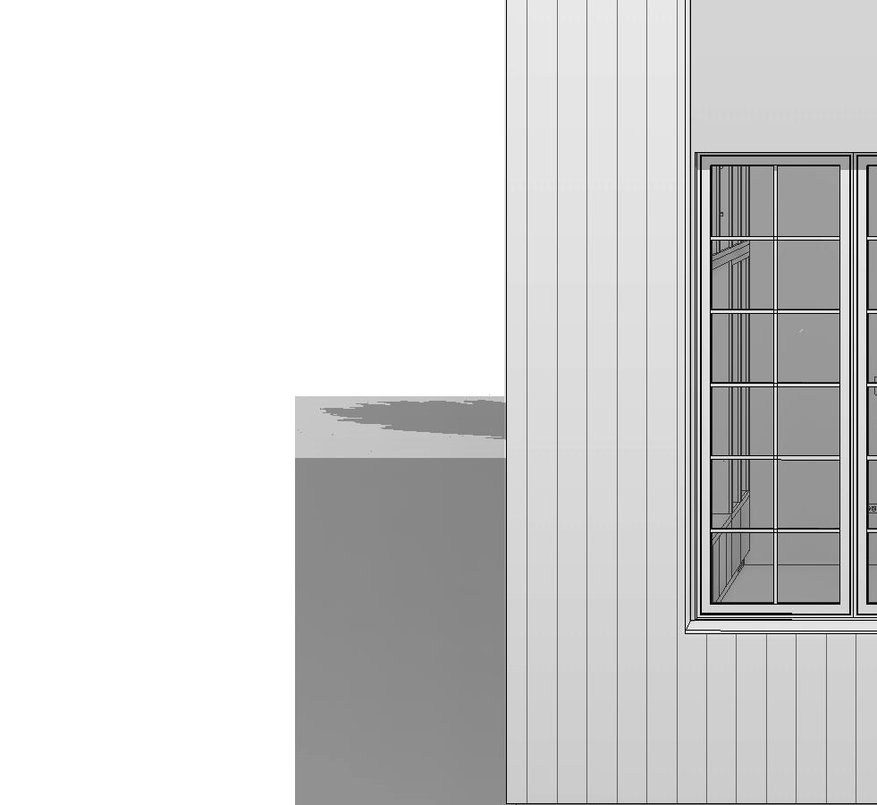
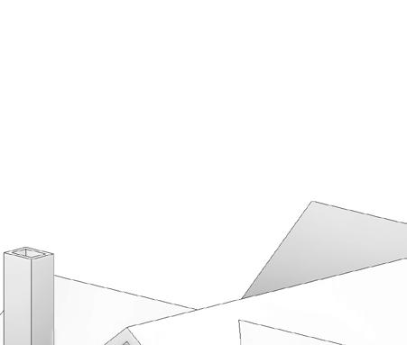
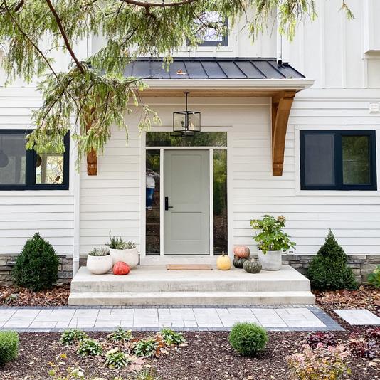
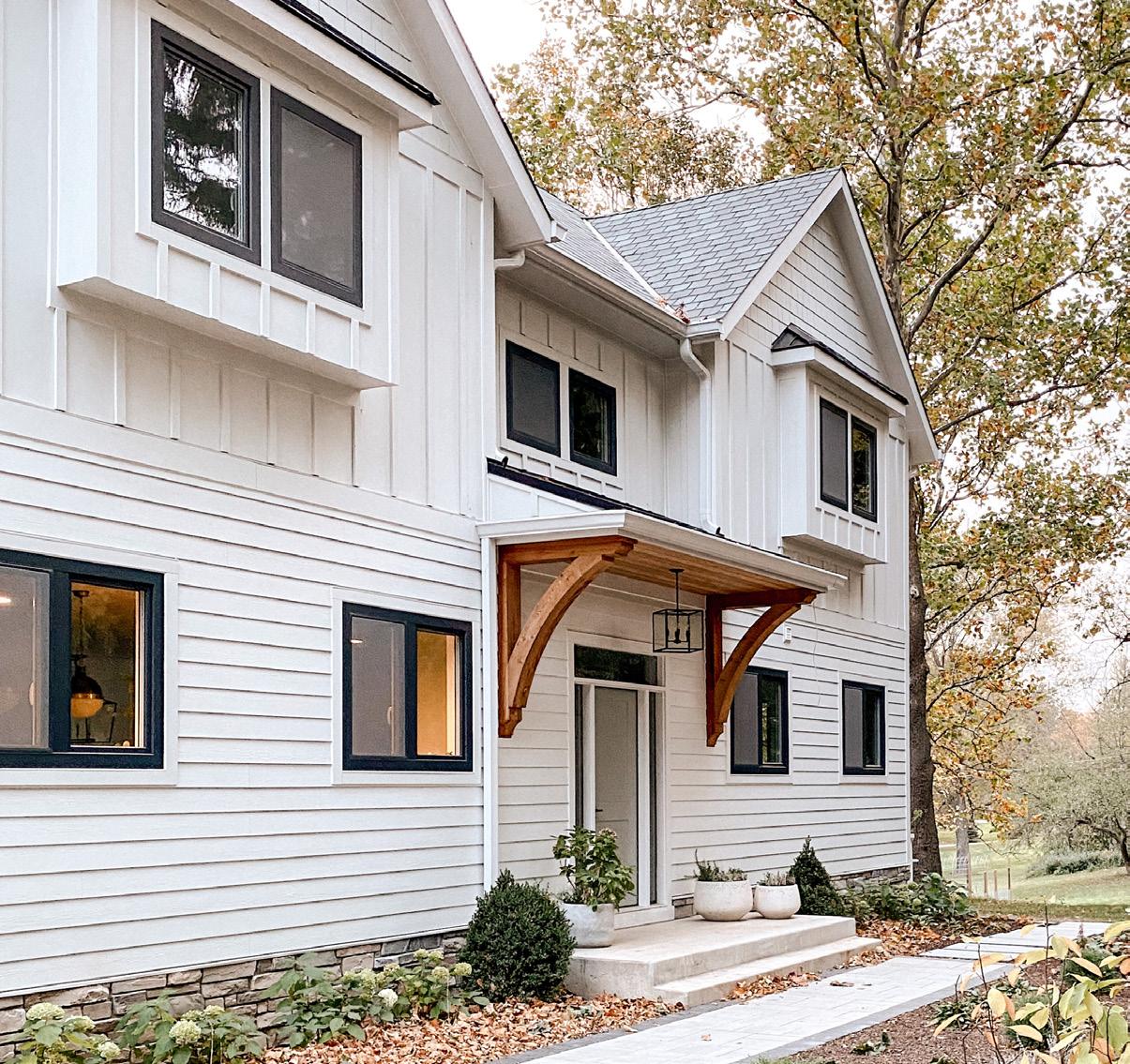
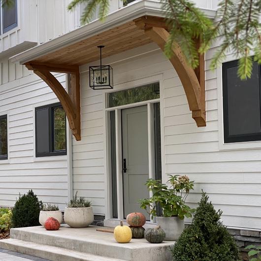
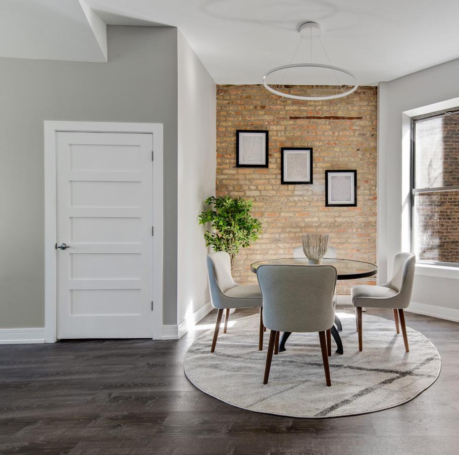
rear addition + adu
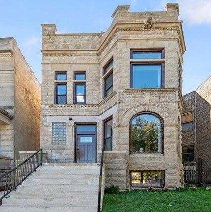
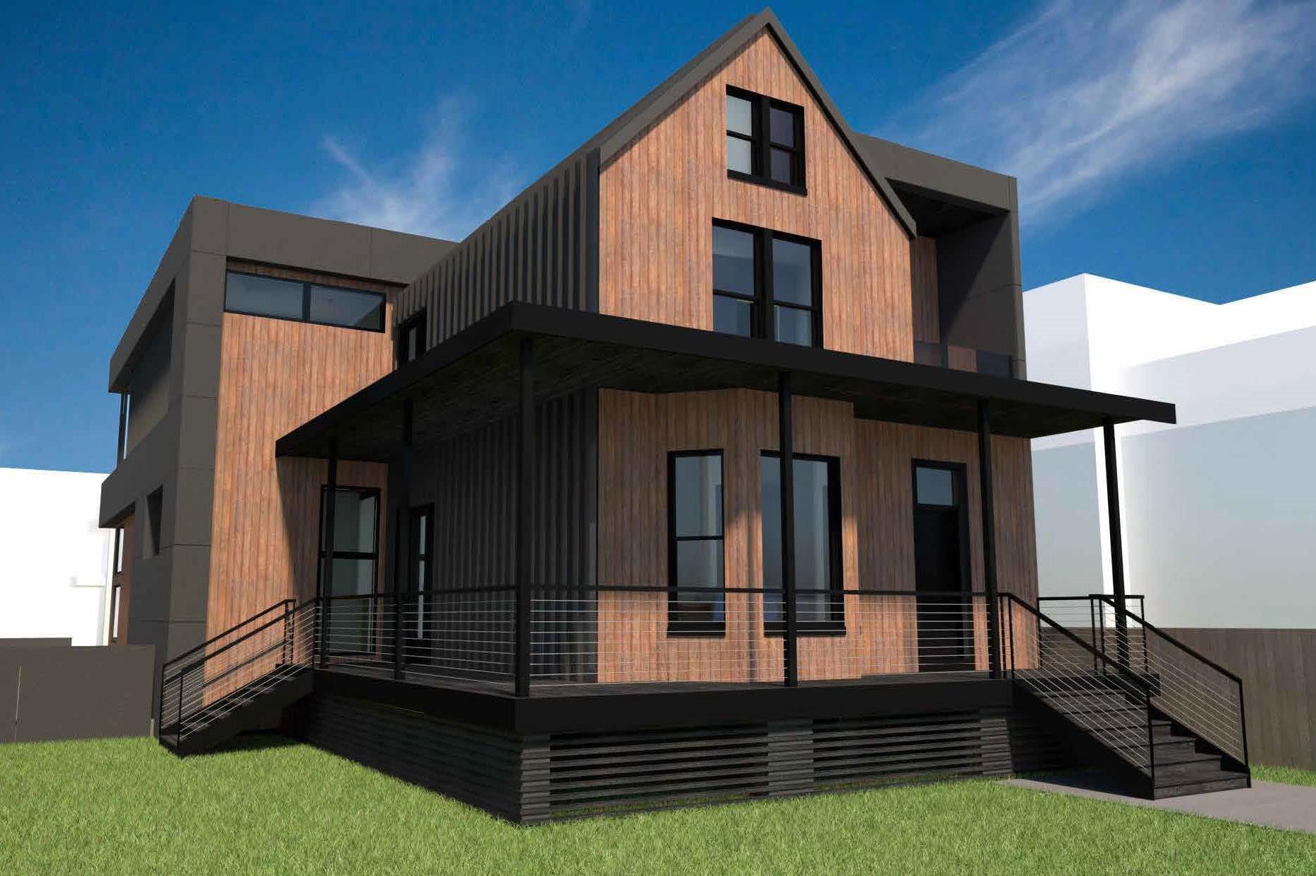
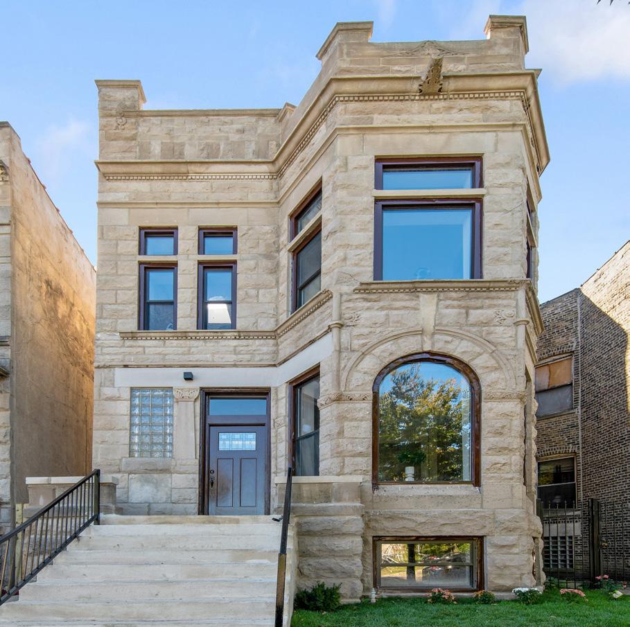
An old Victorian style home was given a new modern look with the use of new materials, and a large forty by forty feet addition. The site is a generous 50’x160’ which allowed to fit all of the programs requested by the owners. Existing vinyl siding was replaced with equitone panels, standing seam siding, and natural cedar - consistent throughout the entire building.
6 01
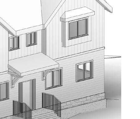
ravenswood residence
FRONT RENDERING
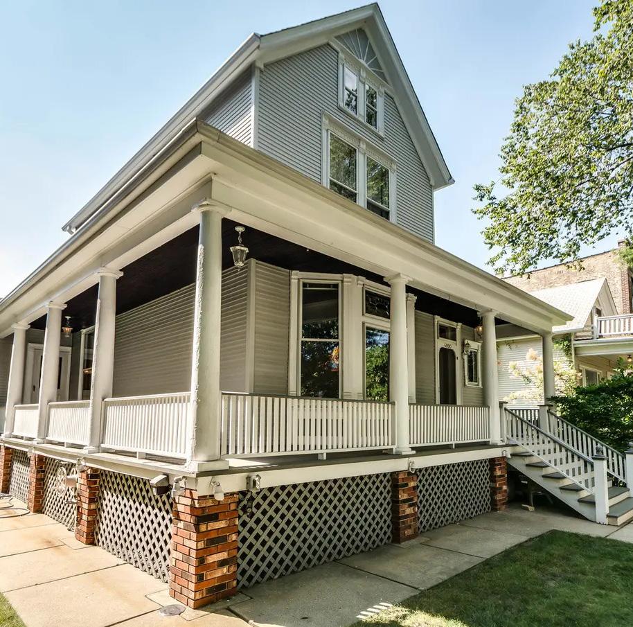
EXISTING BUILDING
The existing house was last renovated in the 1990’s. Front of the house will be maintained, while providing new insulation, cladding, replacing windows, and rebuilding the front porch.
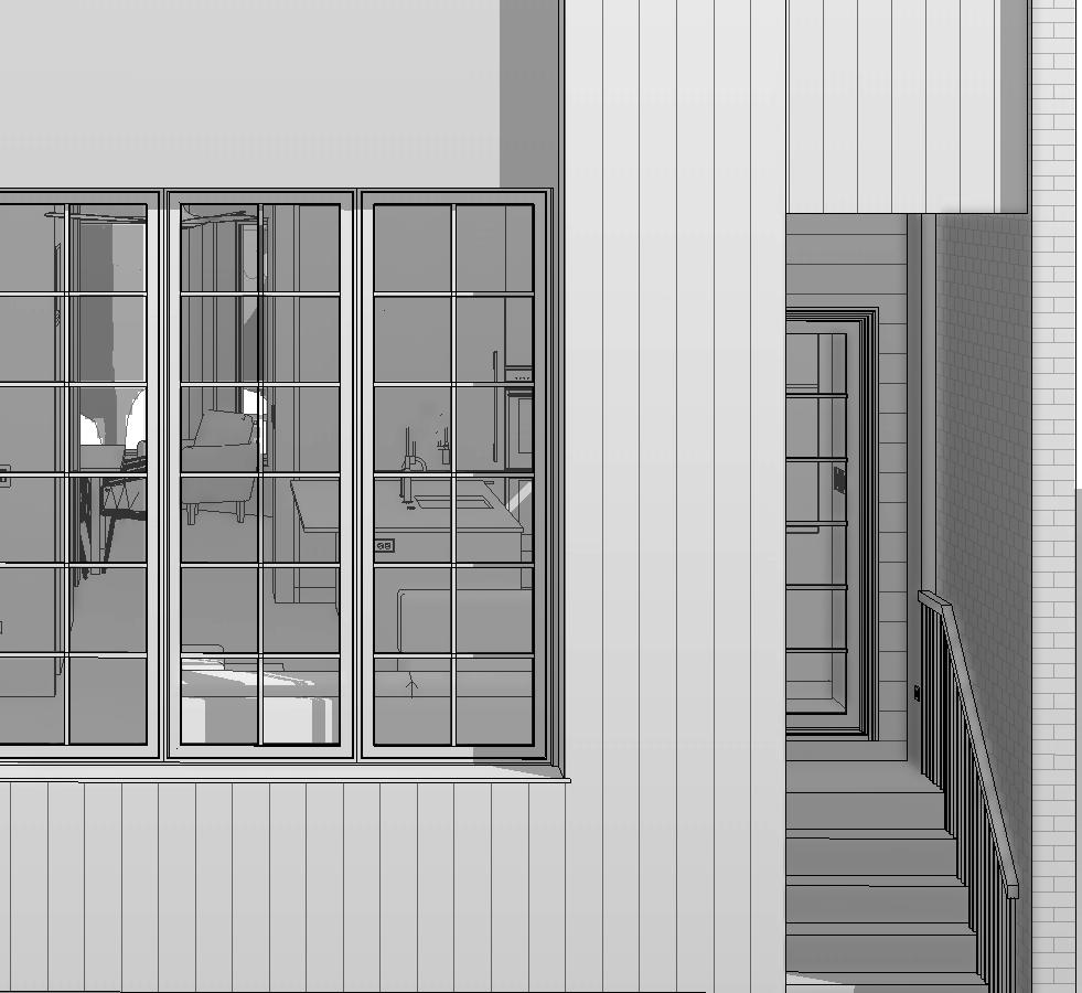
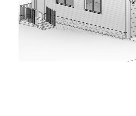
MODERN REAR ADDITION
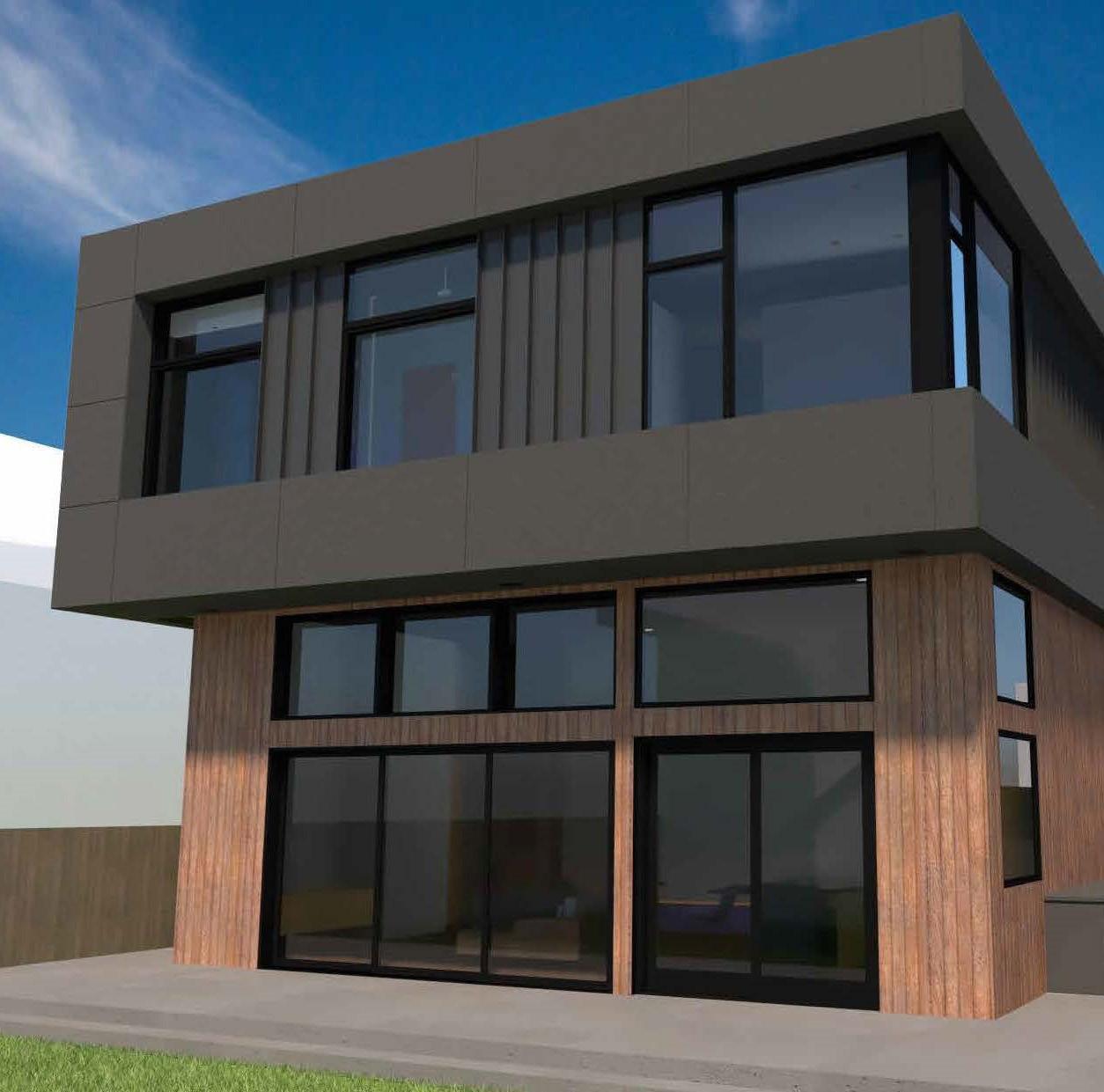
The rear of the existing building was removed, and an addition was placed on grade level, which allows for a better connection to the yard
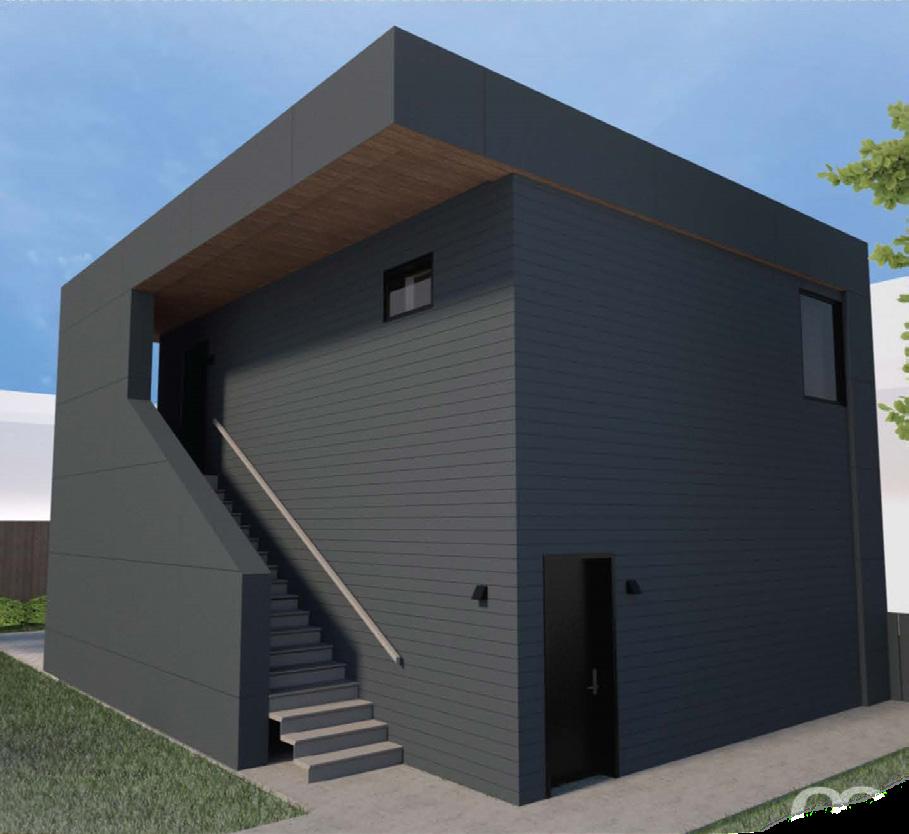
ADU + Garage
An ADU unit was also a part of this project. The studio unit on the second floor will be rented out, while the garage below will be housing the owners’ electric vehicles.
7 chicago, illinois | 2021
01
ravenswood residence floor plans + sections
LEVEL 1 FLOOR PLAN
The main living area is sunken down from the existing first floor level. The near forty by forty addition is a radiant slab on grade - giving a modern appearance as well as thermal comfort throughout the year.
8 DN DN DN 2 A 3.3 2 A 3.4 1 A 3.4 1 A 3.3 B.1 C 1 2 R 9 3/4" 29' 9 1/2" 9 3/4" 46' 11" 16' - 0" 7' - 10 1/4" 5' - 0" 5' 10 3/4" 5' 6 1/2" 40' - 7 3/4" Undercounter Beverage cooler 17' - 0 1/2" 3' - 1" F 5' 9" 6' - 3" 3' 4 1/2" 5'9" 2' 0" 9' - 0 1/4" A 3.2 2 A 3.1 2 A 3.1 1 374 SF Family Room 101 292 SF Kitchen 102 96 SF Coffee 103 191 SF Office Lounge 108 69 SF Mud Room 100 32 SF Powder 105 76 SF Butler 104 Closet 208 216 226 TYP. 226 E100 105 E101 E102 110 8 SF Closet 110 2' 6 1/4" E108 106b 10 20 14 15 15 16 23 261 262 a4 a4 a4 f6 a4 a4 e6 e6 e6 e6 e6 D E F 5 6 e6 Oven 9 3/4" 38' 1 1/2" 9 3/4" 6'2 1/2" 1' - 4 3/4" 3' 7 1/2" 2' 1' 10" 6' - 0" e4 68 SF SITTING 101a Fire Place 16' - 4" 6' 4 1/2" 6' - 1 3/4" 4' 1" 1' 8" a4 a4 3' 6" 19' 9 1/2" 4' 0" 262 262 31' 5" 15' 3 1/2" Closet 111 7' - 0" 6' 9" 3' 11 3/4" 111 3'6 1/4" 19' 4" 11' 7" 09 4' - 9 3/4" e6 a4 a4 262 26 R @ Std T@ 0' - 7 3/32" 6 0' - 10" R @ Std T@ 0' 6 25/32" 7 0' 11" 260 260 2' 8 1/2" bench 36" counter millwork console 36" counter 38" H Island 38" H counter 18" H stone counter 5' - 10 1/4" R @ Std T@ 0' 7 9/32" 14 0' 10" 19 R @ 0' - 7 Std T @ 0'New Hardwood flooring on plywood substrate, 3'4" 3'0 1/2" 268 11' 3 1/2" 4'0" 228 DEU2450BGL Exterior Soffit 17' - 10 3/4" a4 2 A 3.5 3' 0" 0 1' 0" 4' - 0"2' - 0" 269 2' - 5 1/2" 10 D.2 D.1 3 1/2" B East Face for New Foundation Wall CL of Foundation Wall & Columns CL of Column Exterior Face of Foundation & Sheathing CL of Column CL of Column Exterior Face of Sheathing (Level 2) Exterior Face of Foundation & Sheathing Exterior Face of Foundation & Sheathing Exterior Face of Sheathing (Level 2) Exterior Face of Foundation & Sheathing CL of Columns Exterior Face of Foundation & Sheathing P 12' -3" 22 22 15 15 16 100 A 3.6 1 A 3.6 4 A 3.6 3 2' -0" 3' 11" 1' 6" 1'10 1/2" 1' 0" step 7" 1' 6 1/4" shelves 263 6' 1 1/2" 6' 1 3/4" 255 211 partial top tread aligned to finished floor ø 3 ft 229 229 6"
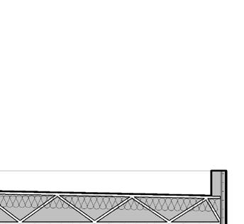
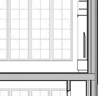
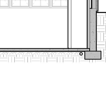
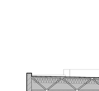
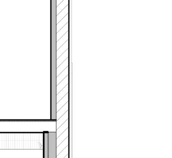
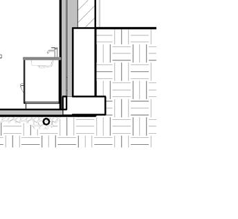
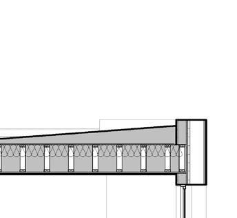
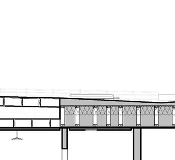
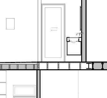
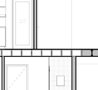
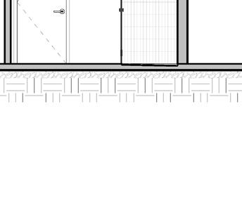
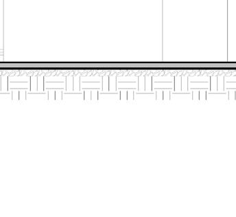
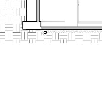
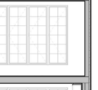
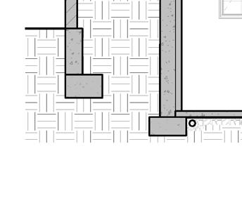
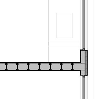
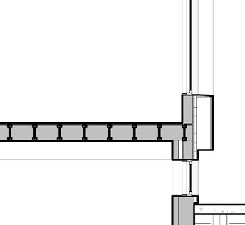
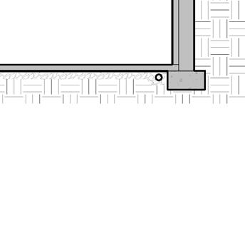
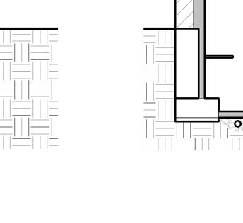
WALL SECTION AT
9 Cedar exterior ceiling soffit on PT furring 16" Open Web trusses at zero threshold showerrefer to structural New intermediate beam, refer to structural Steel beam, per structural 5/8" GWB on suspended ceiling system 4" Rigid insulation Prefinished Aluminum Coping 2x12 PT Exterior Soffit sloped aluminum window sill 2x12 PT Exterior soffit outriggers supporting exterior soffit - refer to structural Open web roof trusses with sloped top chord .060 TPO Roofing Membrane (UL Class A Rated) Plywood Sheathing 18" Open web floor trusses 5/8" GWB on resillient channel Foundation wall & footing, per structural Radiant slab on grade 13'0" A 3.6 8 Roof cant 3'2" 8'6" 4'0 1/4" 12' 9" 4" LED Strip lighting refer to Lighting plans sound attenuation batt insulation 2' 0" 4" concrete patio aluminum flashing on top of outrigger A 3.6 7 cellular shade housing Continuous recessed curtain track 1-1/2" Rigid insulation 5/8" Type x GWB Parapet 29' - 5 1/8" 7 6 Header at bottom of the truss Window Ceiling Exterior soffit, Provide 1-1/2" Rigid insulation at the entire perimeter Extend joists (beyond) Joist hanger Built-up saddle per roof plan Pre-finished Aluminum Coping Composite panel cladding Rigid insulation over plywood Parapet 29' 5 1/8" 7 6 Steel Beam Window Ceiling Joist hanger Built-up saddle per roof plan Exterior soffit, Provide 1-1/2" Rigid insulation at the entire perimeter Pre-finished Aluminum Coping Composite panel cladding Rigid insulation over plywood New curb mounted skylight Framing Header per structural 2x built up wood curb, per manufacturer's requirements TPO roofing membrane Continuous rigid insulation Open Cell Spray Foam Cavity Insulatiion Laminated safety glass unit T.O Roof Level 2 Ceiling 5/8" GWB refer to roof assembly 3/2/23 8:08:36 PM 3 Wall Section - West Exterior Wall Section Scale: 1/2" = 1'-0" 4 Header Section 1 Scale: 1/2" = 1'-0" 5 Header Section at Steel Beam 6 Curb Mount Skylight Section
A 23' - 5" 31' - 6 3/4" 6' 6" 13' - 0 1/4" 15' 3 1/2" 30' 2 1/2" A 3.2 1 219 SF Dining 109 205 SF Hallway 106 36 SF Vestibule 107 243 02 02 03 6'7" 24' - 10" 4" e4 e4 e4 3 217 217 217 4' 10 1/4" bench 262 262 262 262 217 7/16" 9" Hardwood existing substrate, typ. New Wood porch. Refer to Structural. New wood steps. Refer to Structural. New radiant concrete steps with stone paver treads Refer to Structural for footing 243 1 A 3.5 07 4' 0" 207 11" 237 201 UP carpet runner 9' 4" 5'6" 207 207 221 221 A D.2 4 106 107 8' 10" Date: Sheet: Drawn: Copyright 2023, moss Design, Inc. All ideas, designs, arrangements, and plans indicated or repres ented by these drawingsare owned by, and property of moss desig n, inc, and were created, evolved, and developed as instruments of service on, and connection with the specified project and site. None of these ideas, designs, a rrangements, or plans shall be used by or disclosed to any pers on, firm, or organization for any purpose whatsoever without wr itten permission of moss design, inc. 2855 W Diversey Avenue Chicago, Illinois 60647 773.857.5533 moss-design.com moss MaziarzRomero House 4890 North Hermitage Avenue Chicago, IL 60640 02.22.2023 A 2.1 Keynotes: 201New carpenter built stair with oak finish treads and risers. Provide carpet runner. 207Provide new cladding on existing exterior wall framing - refer to wall assemblies 208New carpenter built stair with capet finish 211New concrete stairs - refer to structural for reinfocement information 216New mechanical shaft 21736" handrail guardrail with cable infills at 4" o.c. (Typ) 221Composite decking - BOD: Trex Select Winchester Grey 226New radiant concrete slab - Refer to structural 228New 36" wall mounted handrail 229New 36" high steel handrail guardrail 237Scupper roof drain and downspout. Connect to existing municipal sewer line. 243New concealed aluminum, box type gutter and downspout to run along front of structural column. Provide metal fascia. Refer to detail on A 3.6 255Internal downspout in exterior soffit 260Exterior soffit with specified cladding (uninsulated where outside of drainage plane of insulated building envelope. 261New concrete patio with exposed aggregate finish. 262New column - refer to structural 263Edura Flap - double flap wall mount pet door (black) 268Remove existing grille, infill and patch opening 269Modify existing cased opening to accomodate a undercabinet pass through refer to detail on sheet A7.2 revision description date Issued for Construction 02.22.2023
ADDITION
01 ravenswood residence
floor plans
LEVEL 2 FLOOR PLAN
The upper level consists of 6 bedrooms, three of which were maintained from the existing. The west wall overhangs to creat more space.
10
DN 2 A 3.3 2 A 3.4 1 A 3.4 1 A 3.3 B.1 C 1 2 8' 5 1/2" 3' 4" 5' 8 1/4" 13'7 3/4" 9 1/4" 34'1 1/2" 10 3/4" 6' 0 1/2" 17' - 7 1/4" 9' 4" 9'11 3/4" 9' - 11 3/4" 7' -5 1/2" Shear wall 3' 6 1/2" 1' -2 3/4" 17' - 7 1/4" 10' - 11" A 3.2 2 A 3.1 2 A 3.1 1 35' 9 1/2" 176 SF Bedroom 5 214 52 SF Bath 3 215 158 SF Master Bath 211 336 SF M. Bedroom 209 44 SF Bath 4 212 115 SF Bedroom 2 203 96 SF East Hall 200 48 SF Bath 2 213 65 SF M. CL 210 10 5 SF CL 205 95 SF West Hall 208 211b 211c 214 209 215 213 12 13 18 17 28 27 3' - 6" e6 e6 e6 e6 f6 a4 a4 a6 a4 a6 a4 a6 a6 a4 a6 a4 a6 a4 D E F 5 7 6 5' 6 1/2" 14' - 11 3/4" 9 3/4" 1/4" 1'-0" 4' - 0" 10 1/4" 17' - 7 1/4" e4 210 180 SF Bedroom 4 217 6' 0" 5' 1 3/4" 7' - 6" Laundry 216 10' -6 3/4" 7' - 10 3/4" 3' - 6" 9' - 3" 2' 3' - 6" 11' - 5 3/4" 9' 1 1/2" 3'6" 5' -0" 1' -0" Fire Place Flue Shaft 6"2'0" 2' 22' - 0 3/4" 1' 9 1/2" 38' - 3" 62' 6 1/4" 11 3/4" 8' 8 3/4" 1' - 4" 11 29 29 8' - 10 3/4" 217 212 216 6' -6 3/4" 1' 8" 2' - 10"3 1/2"6' 7 1/2" 8' 8 1/4" 14' 0" 6' - 0 1/2" 6" 20 19 21 19 08 25 21 24 1' 3" 2' - 5" 2' 5" a4 2' -5 3/4" 4" 3' 0" a4 8" 2' - 9" 17' - 7 1/4" e6 2'5 3/4" 2'6" 2' 6" 4'2 1/2" 8' 9 1/2" 262 7' - 6" e6 260 260 closet closet frosted glass 262 1'0" 3' 6 1/4" 19' 4" 11' 7" 1' 0" New 36" Guardrail Tub Washer Dryer Slope A 7.9 2 38 38 37 37 201 203 266 267 2 A 3.5 Provide structural panels over existing stud wall. Refer to structural Provide structural panels over existing stud wall. Refer to structural Shear wall 0 20 2' - 3" 2' 3" 3' 11 1/2" D.2 D.1 B East Face for New Foundation Wall CL of Foundation Wall & Columns CL of Column Exterior Face of Foundation & Sheathing CL of Column CL of Column Exterior Face of Sheathing (Level 2) Exterior Face of Foundation & Sheathing Exterior Face of Foundation & Sheathing Exterior Face of Sheathing (Level 2) Exterior Face of Foundation & Sheathing CL of Columns Exterior Face of Foundation & Sheathing 13 30 3' - 1" 20 A 3.6 6 3 A 3.4 210 210 9 1/4" 13' 2 1/2" 9' 0" 214 4 A 3.3 8 3/4" 10' 4 1/4" 3' - 0 3/4" 220 220 3' - 2" bench 210 4' - 6" 9' -6" closet module by others 255 2' 7 1/4" Header condition A refer to A 3.4 Header condition A refer to A 3.4 Header condition B refer to A 3.4 Header condition C - refer to A 3.4 Header condition A refer to A 3.4 Header condition B refer to A 3.4 251 skylight skylight Master Bedroom Entry


11 A 8'0" 11' - 8" 8" 12' - 9 3/4" 1 196 SF Bedroom 3 202 88 SF Bedroom 1 201 18 SF CL 207 10 SF CL 206 241 243 1/4" 1'-0" e4 e4 e4 - 9 1/4" 2' 6"2 1/2" 11 1/4"5' - 3 1/4" 6' - 2 1/2" 3 24' - 3 3/4" 11 1/4" 28' - 5" 252 243 30' 11 3/4" 31' - 4 1/4" New Attic access hatch above for mechanical equipment access. 34 34 33 33 202 266 266 232 1 A 3.5 Extend exterior wall to proposed parapet level e4 3'0" 201b 9" 230 Balcony 224 a4 237 Black TPO Roofing Black TPO Roofing 4" 6 1/2" A 3.6 5 1/4" 1'-0" Roof curb over roof beam, refer to structural Copyright 2023, moss Design, Inc. All ideas, designs, arrangements, and plans indicated or repres ented by these drawingsare owned by, and property of moss desig n, inc, and were created, evolved, and developed as instruments the specified project and site. None of these ideas, designs, rrangements, or plans shall be used by or disclosed to any pers on, firm, or organization for any purpose whatsoever without wr 2855 W Diversey Avenue Chicago, Illinois 60647 773.857.5533 moss-design.com MaziarzRomero House A 2.2 Keynotes: 210Tile shower base with waterproof membrane pan. 214Zero Threshold shower refer to detail on A D.1 and structural drawings 220Standard Threshold shower refer to detail on A D.1 and structural drawings 224Extend existing wall to support new roof rafters above 230Retractable screen mounted to outside face of door frame 232New 36" tempered glass guardrail mounted to existing roof framing. 237Scupper roof drain and downspout. Connect to existing municipal sewer line. 241New Black TPO roofing over new roof framing refer to structural 243New concealed aluminum, box type gutter and downspout to run along front of structural column. Provide metal fascia. Refer to detail on A 3.6 251Furr out wall to align with adjacent 2x6 wall 252Trex composite decking on PT wood sleepers 255Internal downspout in exterior soffit 260Exterior soffit with specified cladding (uninsulated where outside of drainage plane of insulated building envelope. 262New column - refer to structural 266New wood door panel in existing casing. Refer to detail on sheet A D.2 267Remove and replace existing hardwood treads and risers on existing staircase 2'4'6'8' Issued for Construction 3/2/23 8:10:10 PM 1 SE Isometric 3 SW Perspective 4 NW Perspective Date: Sheet: Drawn: 2855 W Diversey Avenue Chicago, Illinois 60647 773.857.5533 moss-design.com moss MaziarzRomero House 4890 North Hermitage Avenue Chicago, IL 60640 02.22.2023 A 9.3 Perspectives not to scale 1 SE Isometric 2 SW Isometric 3 SW Perspective 5 SE Perspective revision description date Issued for Construction 02.22.2023
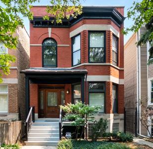
REAR ADDITION
The property for a young couple became a full interior renovation and a rear addition project. On a typical sized lot, a balance of the building and the yard space was considered. The footprint of the existing porch was realized, which allowed for a minimal depth and encroachment of the addition into the yard.
Keynotes:


12

13 chicago, illinois | 2022 2 2 2 / 2 3 1 0 5 1 2 3 A M
REAR BUILDING ISOMETRIC
FRONT BUILDING ISOMETRIC
lakeview residence floor plans
FRONT ELEVATION IS MAINTAINED
14
02
LEVEL 2 FLOOR PLAN
15 UP DN DN DN A 3.1 A 3.1 A 3.1 3 2 1 1 D A 3.1 4 C 4 1 A 3.2 2 A 3.2 3 A 3.2 2 B A 230 SF Dining / Sitting 102 68 SF Entry 101 247 SF Kitchen 106 268 SF Living Room 107 25 SF Pantry 105 23 SF Powder 104 28 SF Hall 103 19 SF Rear Entry 108 105 104 108 102 x12 x12 x12 e6 9' 5 1/2" 1' 8 3/4" 3/4" 4' 2 3/4" 9 3/4" 14'10" 1' 2 1/4" 17' 11" 9 1/4" 4' 6 1/2" 4' 0" 3' 5 1/2"2' 1" 6' - 5 1/4"4 3/4"2' - 0 1/2"4' 0" 10' - 11 1/2" 5' - 4 3/4" f4 a4 a4 a6 a4 a4 e6S e6 44' - 7 1/4" 7' - 4 1/4" 4' - 3 1/4" 240 241 5'1" 2' 8 3/4" 3' 5" Closet 3 24 24 A 7.1 2 5' - 6" 5' 4 3/4" a6 2' 1/4" 10' 8" 1' 10 3/4" f4 3' - 3 3/4" 23' 7 3/4" 11' 2 1/4" 7' 9 1/2" 1' 4 3/4" 17' - 9 1/4" 9 1/4" 22' 4 3/4" 1 1/4" 21' 5 1/2" 3" 5'1 1/2" 4' 9 1/2" 11' 6 1/2" 13' 3" 1' 8" 14' 1" 5' 1 3/4" 1-hr 1-hr 4' 3" 4' 7" R @ Std T@ 0' - 7 1/16" 7 0' - 11" 3' 6" 5' 6" f4 243 215 21 21 21 21 Shear Wall e6S Shear Wall 1-hr 211 2' - 0" 101a 230 2-hr 1-hr f4 1-hr 1-hr 1-hr R @ Std T@ 0' - 6 11/16" 16 0' - 10" 02 03 02 06 07 13 A D.1 a4 a4 1-hr New Floor Tile New Hardwood Floor (Typ) New Hardwood Floor (Typ) 36" wall mounted handrail Existing 36" Handrail and guradrail Paint Existing Wood steps and front porch 3 1/4" 4" 36" high Island 36" high counter Oven Referigerator shelves refer to Detail 1b/A 7.1 refer to Detail 1a/A 7.1 New 2-wythe Masonry wall niche f6 f4 25 25 04 04 2' 2"3' 6" 5' 1 3/4" 3' 0" 10' 10" 3' 0" 215 8' - 0" Exterior Face of New Masonry Wall Exterior Face of Sheathing Foundation CL of L2 Steel Beam & Basement Bearing Wall Exterior Face of Sheathing Foundation Exterior Face of Sheathing Foundation Exterior Face of Existing Masonry wall (Rear) Exterior Face of Existing Masonry wall (Front) Exterior Face of Sheathing (Level 2 Recessed Wall) 5 North Exterior Face of Existing Masonry Wall Millwork, by others cooktop (ex) A 3.3 6 248 248 C.5 Existing stair opening 7 A D.1 216 D C 4 2 A 3.2 3 A 3.2 B A 82 SF Mech 007 241 11' 9" 2' - 5 1/4" 15' - 9" 44' - 7 1/4" 11' 10" 10' 1 1/2" x8 x12 1 1/4" 3/4" 1' 7 1/2" 7' - 4 1/4" 4' - 3 1/4" 2-hr 15 T/F: +0' -6" Exterior Face of New Masonry Wall Exterior Face of Sheathing Foundation Exterior Face of Existing Masonry wall (Rear) Exterior Face of Existing Masonry wall (Front) Exterior Face of Sheathing (Level 2 Recessed Wall) 5 North Exterior Face of Existing Masonry Wall 248 C.5 Existing stair opening 8' - 0" LEVEL 1 FLOOR PLAN DN 1 1 A 3.2 273 16' 10" 30 272 1/4" / 1'-0" 274 36' - 5" existing roof framing to remain 272 3" 287 287 287 1/4" / 1'-0" New Aluminum coping New Aluminum Exterior Face of Sheathing Foundation 16' 4" A 3.1 A 3.1 A 3.1 3 2 1 1 D A 3.1 4 C 4 1 A 3.2 4 A 3.2 2 A 3.2 3 A 3.2 2 B A 211 SF Primary Bedroom 208 86 SF Hallway 201 134 SF Bedroom 1 202 127 SF Bedroom 2 204 59 SF Bath 206 109 SF Primary Bath 207 108 SF Primary Closet 209 58 SF Mech / Laundry 210 10 SF Closet 203 10 SF Closet 205 19' - 2" 25' - 5 1/4" 7' 4 1/4" 4' 3 1/4" 12' 1 3/4" 205 203 202 204 206 208 209a 209b 210 01 210 240 201 a6 e6 e6S e6 44' 7 1/4" 11' 7 1/2" 1' 0 1/4" 5' 1 1/2" 4' 1/2" 11' 6 1/2" 11' 9 1/4" align align align align 12' 6" 2' - 0" 5' 8 1/4" 3' 5" 4' 4" 1' 0" 1' - 0 3/4" 18' - 1 1/4" 5' 3/4" 10' 10" 3' 1" 12' 3 1/2" 10' 8 1/2" 2' - 6" 7' 1" 3' 1 3/4" 5' 0 1/4" 10' 5 1/4" 13' 11" 3 21 21 21 21 2' 3 1/4" 10' 8" 2' 3 1/4" a6 11' 10 1/2" 1 1/4" 21' 5 1/2" 3" 4' 10 1/2" 9 3/4" 15' 1/2" 9 3/4" a6 3' 6" x8 207 x8 a4 1-hr f4 f4 f4 f4 4' - 8 1/2" 6' - 0" 8' 7 3/4" 2' 1 3/4" 05 08 1' - 1 1/2" 64 SF Den 211 8' 3 1/2" existing stair opening 9' 9 3/4" 1-hr 5'2" 5' 2 1/2" a6 5' 0 3/4" a4 a4 a4 a4 a6 F-2 215 e6S 1-hr Shear Wall 1-hr Shear Wall e6S 1-hr 215 226 1-hr 2-hr 2-hr 1-hr 03 02 02 36" Guardrail W/D Fan Coil Skylight above 3' - 4"1' 5" 1' 9" 3'4" New Hardwood Floor (Typ) desk 22 10 1/4" 2' 1/4" 05 1' 2 1/4" 1' 2" f4 Kitchen exhaust riser, refer to mechanical floor drain New 2 wythe masonry wall 3' - 1 3/4" 5' - 4 1/2" 3' 0" 4' 0" 09 26 25 25 04 04 3' 10" 3'0" 10'10" 3'0" 19' 3" Exterior Face of New Masonry Wall Exterior Face of Sheathing Foundation CL of L2 Steel Beam & Basement Bearing Wall Exterior Face of Sheathing Foundation Exterior Face of Sheathing Foundation Exterior Face of Existing Masonry wall (Rear) Exterior Face of Existing Masonry wall (Front) Exterior Face of Sheathing (Level 2 Recessed Wall) 5 North Exterior Face of Existing Masonry Wall 11' 5 1/4" 1' 8" Millwork A 3.3 6 1' 3" 7' 9" 5' 0 1/4" 3' 8" C.5 Existing stair opening 3 1/4" 3 1/4" 6 A D.1 f4 align 7 3/4" 3 Roof
lakeview residence elevations and sections

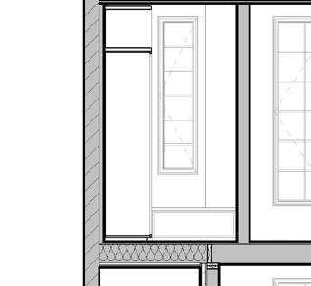
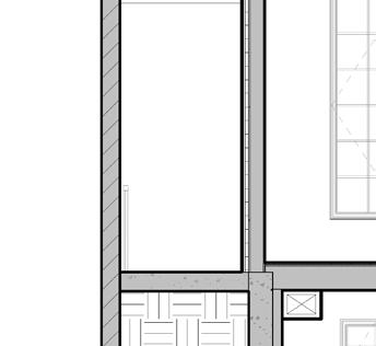
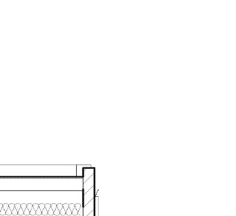
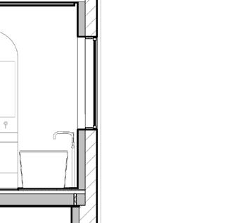


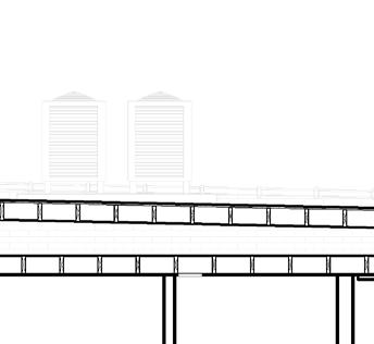
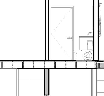
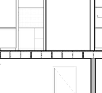
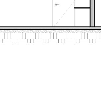
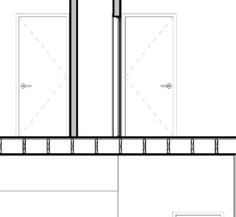
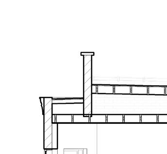

Building Sections
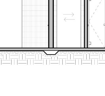
16 Level 1 4' - 5 1/4" D C Grade 0' - 0" Level 2 15' - 5" Basement -4' - 5 1/2" Roof 30' - 11" 4 A 3.2 2 A 3.2 3 A 3.2 Ex. Basement -3' - 5" B A Level 2 Ceiling 25' - 5" T/ Addition 28' - 5" Primary Bedroom 208 Primary Bath 207 Living Room 107 Guest Bedroom 004 Bath 003 Study Office 002 Family 001 Dining Sitting 102 Powder 104 Bath 206 Bedroom 2 204 Bedroom 1 202 Hall 103 e6S e6S e6S 10' 0" 10' 0 1/4" 7' 11 1/4" A 3.3 1 327 328 W10 W10 1-hr W9 1-hr 311 hsg sg W91-hr 1-hr R10 324 R16 1-hr Existing ceiling joists to remain align Existing floor joists to remain Existing floor joists to remain Existing roof rafters to remain Provide roof cricket and slope to drain New radiant concrete slab New floor joists New floor joists align New roof trusses 311 28' 5" Pantry 105 C.5 A D.1 15 10' 0" x8 x8 x12 313 324 2-hr 2-hr and ceiling joists Existing Floor Existing foundation Level 1 4' - 5 1/4" 1 Grade 0' - 0" Level 2 15' - 5" Basement -4' - 5 1/2" 2 Ex. Basement -3' - 5" 3 Level 2 Ceiling 25' - 5" T/ Addition 28' - 5" Primary Closet 209 Living Room 107 Primary Bedroom 208 Guest Bedroom 004 312 312 328 e6 e6 W10 W10 e6 1-hr 1-hr 1-hr 1-hr R16 1-hr New radiant concrete slab New floor joists New floor joists New roof trusses with sloped top chord 10'2 3/4" 28' 5" Flush LVL beam, refer to structural 318 Bedroom 1 202 Dining Sitting 102 Family 001 Steel beam, per structural 319
as noted 310New Masonry wall 311Exterior soffit with wood plank cladding 312New foundation wall and footing at new exterior 313Existing foundation wall to remain 318Mechanical ductwork soffit w/ 5/8" GWB 319Steel beam soffit w/ 5/8" GWB 323New concrete stairs and landing refer to structural 324Reframe portion of exisitng floor to accomodate 3255/8" Exterior Sheathing, 7/8" Resillient Channel, 326Provide R-30 Cavity Insulation 327New Steel beam to be recessed within exisitng 328New perimeter drain tile below new concrete Keynotes: 02 LONG SECTION
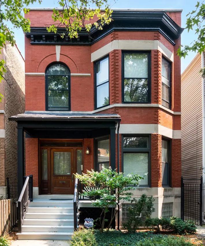
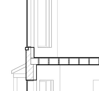
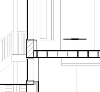
Level 1 4' - 5 1/4" C Grade 0' - 0" Level 2 15' - 5" Basement -4' - 5 1/2" Roof 30' - 11" 2 A 3.2 3 A 3.2 Ex. Basement -3' - 5" B A Level 2 Ceiling 25' - 5" T/ Addition 28' - 5" Primary Bedroom 208 Primary Bath 207 Living Room 107 Guest Bedroom 004 Bath 003 Study Office 002 Powder 104 Bath 206 Bedroom 2 204 Hall 103 e6S e6S e6S 10' 0" 10' 0 1/4" 7' 11 1/4" A 3.3 1 327 W10 W10 1-hr W9 1-hr 311 hsg sg 1-hr 324 R16 1-hr Existing ceiling joists to remain align Existing floor joists to remain Existing floor joists to remain Existing roof rafters to remain Provide roof cricket and slope to drain New radiant concrete slab New floor joists New floor joists align New roof trusses 311 28' 5" Pantry 105 C.5 A D.1 15 10' 0" 1 327 Pantry 105 x8 x12 313 Hallway 005 Bath 003 Primary Bath 207 324 Existing Floor joists to remain A D.1 15 Level 1 4' - 5 1/4" 1 4 Grade 0' - 0" Level 2 15' - 5" Basement -4' - 5 1/2" 2 Ex. Basement -3' - 5" 3 Level 2 Ceiling 25' - 5" T/ Addition 28' - 5" Primary Closet 209 Living Room 107 Primary Bedroom 208 Guest Bedroom 004 312 312 328 310 e6 e6 W10 W10 323 e6 1-hr 1-hr 1-hr 1-hr 1-hr R16 1-hr New Foundation Wall & Footing per structural New radiant concrete slab New floor joists New floor joists New roof trusses with sloped top chord x8 4' 1 1/4"4" 10' 2 3/4" 325 326 6" 27' 11" 28' 5" 5 Flush LVL beam, refer to structural 318 Date: Sheet: Drawn: Copyright 2023, moss Design, Inc. All ideas, designs, arrangements, and plans indicated or represented by these drawingsare owned by, and property of moss design, inc, and were created, evolved, and developed as instruments of service on, and connection with the specified project and site. None of these ideas, designs, arrangements, or plans shall be used by or disclosed to any person, firm, or organization for any purpose whatsoever without written permission of moss design, inc. 2855 W Diversey Avenue Chicago, Illinois 60647 773.857.5533 moss-design.com moss BenderGeraghty House 3527 North Hermitage Avenue Chicago, Illinois 60657 02.22.2023
as noted 310New Masonry wall 311Exterior soffit with wood plank cladding 312New foundation wall and footing at new exterior wall above refer to structural 313Existing foundation wall to remain 318Mechanical ductwork soffit w/ 5/8" GWB 319Steel beam soffit w/ 5/8" GWB 323New concrete stairs and landing refer to structural 324Reframe portion of exisitng floor to accomodate a zero threshold shower - refer to structural 3255/8" Exterior Sheathing, 7/8" Resillient Channel, and 3/4" PT wood soffit 326Provide R-30 Cavity Insulation 327New Steel beam to be recessed within exisitng floor cavity Refer to Structural 328New perimeter drain tile below new concrete slab Keynotes: e v s o n d e s c p t o n d a e s s u e d o C o n s u c o n 0 2 2 2 2 0 2 3
A 3.2 Building Sections
CROSS SECTION

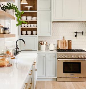
17 PRIMARY CLOSET MILLWORK Rift White Oak open open open open open open open Shoes Closet open open 1/2" recessed filler 10 1/2" 8' 0" 1' 9" 1' 6"1' 6" 3' 0" 3' 0" 3' 0" 2' 0" 2' 0" 1' 6" Hamper Hamper 10" 3' 2" 1' 1' 2" toekick Extend bench into open cabinet Extend bench into open cabinet 3' 0" 3' 0" 3' 0" 4' 0" 1' 6" open open 1' 4" 1' 4" 1' 4" 0" adj shelves adj shelves adj shelves hang rod 6" hang rod 1-1/2" Face Frame at Open Box, Typ. 1 A 7.8 3 A 7.8 2 A 7.8 3' 9" 3' 9" Shoes Closet hang rod hang rod hang rod open open open 6" 6" 1' 0" CN01 LED tape light at underside A 7.6 2 Primary Closet 209 A 7.6 8 7 A 7.6 4 1' 3" 3' 9 3/4" Green Marble Top Bench Bench 4' 9" 3' 0" 3' 0" 5' 0" 3' 6" 5' 3/4" 3 9 open 1' 1 1/2" 1' 1/2" 2" Extend Bench top into open cabinet Extend hang rod into open box 6" open open 3' 6" Typical for all conditions unless noted otherwise 1. Cabinet Boxes to be 3/4" prefinished maple plywood with dado and rabbet joint 2. Drawers to be dovetail, maple, clear coat 3. Blum or Salice soft close hardware for cabinet doors 4. Blum or Salice soft close flip up hardware 5. Hafele or Salice concealed undermount hardware or all drawer pull outs (unless weight requires side mount). 6. Clear maple cabinet interiors, unless noted otherwise 7. Physical samples for owner approval 8. Include shop drawings, delivery and installation Millworker Scope 0" Extend Bench top into open cabinet 6" CN08 6" 2' 0" 2' 6" 2x4 framing CN08 Turn down (miter) 2' 6" 3' 0" 6" 6" Turn down (miter) 0" fixed mirror 2' 0" (2) Sconce EQ EQ EQ EQ 4' 6" CN08 3' 6" 6" 0" Date: Sheet: Drawn: 2 3 0 5 0 A M BenderGeraghty House A Interior Elevations (L2) 5 Isometric -Primary Closet 209 2 Primary Closet 209 -North 1 Primary Closet 209 / Vanity 0' 1' 2' 3' 4' 2' Scale: 1/2"=1'-0" 4 Primary Closet 209 -West o e n a s u e d o C o s u o n 0 2 0 3 3 Primary Closet -East 6 Isometric -Primary Bed 208 Vanity Scale: 1" = 1'-0" 7 Primary Bed 208 -Vanity Section 8 Primary Bed 208 -Vanity 9 Primary Bed 208 -Vanity West A 7.3 1 4 2 2' 1/2" 4' 0" 1/2" 0 1/2" 0" 10' 11 1/2" A 7.3 3 A 7.3 7 A 7.3 8 1' 3/4" 2' 1/2" 15' 11 1/4" 2' 1" 1/2" 1/2" DW Kitchen 106 A 7.3 10 Rift White Oak Cabinets S01 1 1/2"2' 0" 2' 6" 3' 0" 3' 0" 3' 0" 2' 3" 3/4" end panel 2 A 7.7 painted drywall 1' 3 3/4" 4' 0" 3' 0" 3' 0" 3' 0" 1' 7 1/2" Fixed Panel Fixed Panel 12" Deep Shelf 12" Deep Shelf Fixed Panel niche & adjustable shelves (beyond) LED tape light and Plug mold at underside of shelf -refer to Lighting and Power Plan Tile backsplash Tile backsplash 2' 6" 0" Range Hood HP36ILTX1 Cooktop -CI365DTB4 1 A 7.7 Hafele Magic Corner W05 W05 S01 S01 2' 3" Fixed panel pantry 6" 3' 0" 2' 6" 2 1/2" filler 2' 0"1/2" 0" 2" 6" 2' 0" 1' 4" Fixed panel Fixed panel Extend Counter into Cabinet Apliance Garage Outlet in cabinet 1/2" OH 1' 0" Drawers Fisher & Paykel OB30DTEPX3 Fisher & Paykel OB30DTEPX3 Shelf S01 water shutoff located in cabinet 2' 7" 3"1' 4"3" R1/2 10' 11 1/2" 1' 3/4"1' 4 3/4" 1-1/4" ⌀ faucet hole below 1/2" OH 0" 0" 11 1/2" OH 1/2" OH Typical for all conditions unless noted otherwise 1. Cabinet Boxes to be 3/4" prefinished maple plywood with dado and rabbet joint 2. Drawers to be dovetail, maple, clear coat 3. Blum or Salice soft close hardware for cabinet doors 4. Blum or Salice soft close flip up hardware 5. Hafele or Salice concealed undermount hardware or all drawer pull outs (unless weight requires side mount). 6. Clear maple cabinet interiors, unless noted otherwise 7. Physical samples for owner approval 8. Include shop drawings, delivery and installation Millworker Scope Date: Sheet: Drawn: Copyright 2023, moss Design, Inc. All ideas, designs, arrangements, and plans indicat ed represented these drawingsare owned by, an property of moss design, inc, and were created, volved, and developed as instruments of service on, and connection with the specified project and site. None of these ideas designs, arrangements, or plans shall be used by or disclosed to any person, firm, or organization any purpose whatsoever without written permissio moss design, inc. 2855 W Diversey Avenue Chicago, Illinois 60647 773.857.5533 moss-design.com moss BenderGeraghty House 3527 North Hermitage Avenue Chicago, Illinois 60657 02.22.2023 A 7.3 Interior Elevations (L1 -Kitchen) 5 Enlarged Plan -Kitchen 106 9 Isometric -Kitchen 106 1 Kitchen 106 -South 2 Kitchen 106 -West 0' 1' 2' 3' 4' 2' Scale: 1/2"=1'-0" 6 Kitchen 106 -Island Plan o e n a s u e d o C o s u o n 0 2 0 3 A 7.3 1 4 2 2' 1/2" 4' 0" 3' 6 1/2" 2' 1/2" 10' 11 1/2" A 7.3 3 A 7.3 7 3/4" 2' 1/2" 15' 11 1/4" 1" 7' 3 1/2" 1/2" DW Kitchen 106 extend counter into cabinet Rift White Oak Cabinets S02 S01 1 1/2"2' 0" 2' 6" 3' 0" 3' 0" 2 A 7.7 painted drywall 3' 0" 3' 0" 3' 0" 1' 1/2" Fixed Panel 12" Deep Shelf LED tape light and Plug mold at underside of shelf -refer to Lighting and Power Plan Tile backsplash Range Hood HP36ILTX1 Cooktop -CI365DTB4 1 A 7.7 Hafele Magic Corner W05 Fixed panel pantry 1' 6" 3' 0" 2' 6" 2 1/2" filler 2' 0"1/2" 1 1/2" filler 1' 4 1/4" 2' 0" 4" 4" 0" 2" 1' 6" 2' 0" 4" Fixed panel Fixed panel Extend Counter into Cabinet Apliance Garage Outlet in cabinet Dashed line indicates required region of power & water connections behind appliance (4) roll out shelves Full clearance hinge adjustable shelves 1/2" OH 1' 0" Drawers Fisher & Paykel OB30DTEPX3 Fisher & Paykel OB30DTEPX3 3 A 7.7 Shelf S01 water shutoff located in cabinet 3/4"1' 3"1' 3"1' 3" 3' 3" Dishwasher 2' 0" 1' 9"3/4" 3/4" end panel 1/2" OH trash 0" water filter compost 4" 1 1/2" 1 1/2" Black Painted Cabinets Fisher Paykel DW24U6l1 Hafele Waste Bin Pull-Out 2" S02 2' 7" 3"1' 4"3" R1/2 10' 11 1/2" 0" 1' 4 3/4"1' 3/4" 1-1/4" ⌀ faucet hole cabinet below 1/2" OH 0" 1' 0" 11 1/2" OH 1/2" OH 1/2" OH 3/4" end panel1' 9" 2' 0" 3' 3" 2' 0" 1' 9"3/4" end panel 1/2" OH 1/2" OH 1" 2' 7" 4" 1/2" fixed panel Black Painted Cabinets S02 4' 0" 1/2" OH 11 1/2" OH 3/4" End Panel 1' 0"2' 0" 4" 7"1" 3' 0" Black Painted S02 3' 0" 2' 0"1' 0" 1" 7" 4" 1/2" OH 11 1/2" EQEQ 4' 0" 3/4" End Panel 14" Slot cut louver in toekick A 7.7 8 3' 1/4" 0" 3' 0" 3"9"3" Adjustable shelves open Slot cut louver in toekick 2 2 2 0 1 0 A M Enlarged 9 Isometric -Kitchen 106 2 Kitchen 106 -West 4 Kitchen Island -North 6 Kitchen 106 -Island Plan 3 Kitchen Island -South 8 Kitchen Island -East 7 Kitchen Island -West 10 Kitchen -East Niche KITCHEN MILLWORK
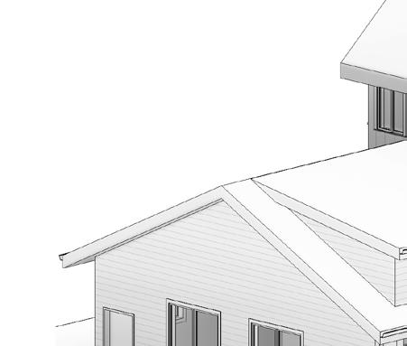


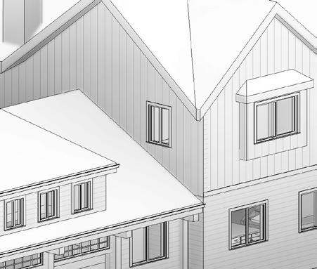

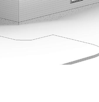
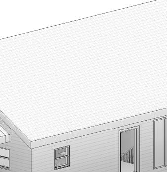


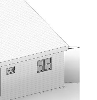

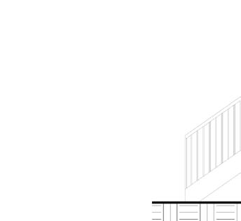
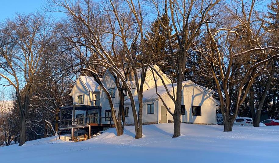
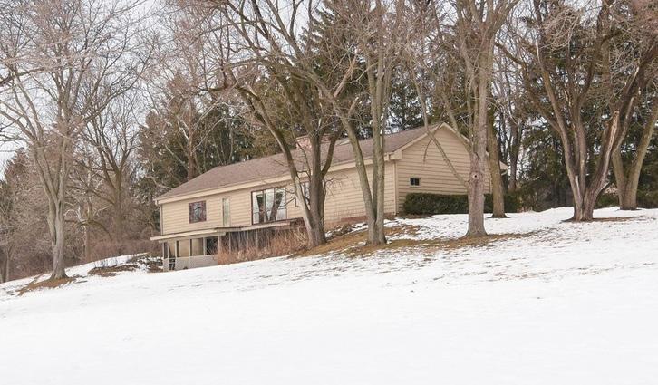
18 Existing SINGLE STORY Completed 2ND STORY ADDITION
The ranch style home that situated on the edge of a 2.5 acre property was given an entirely new floor above. Much of the existing exterior walls were taken down to the foundation wall, making the extent of this project nearly a new construction project.
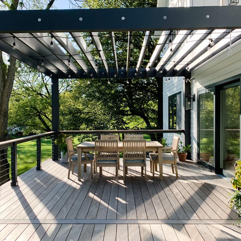
The owners desired a farm style home, with a symmetrical massing from the exterior. This became essential in the layout of the spaces and openings.
A large deck overlooking the property was placed at the middle of the plan. Below the deck becomes a covered walk out patio from the basement level.
19 03
residence 2nd story addition kildeer, illinois | 2018-2019
kildeer
20 LOT 6 2.532 ACRES 2 9 6 8 2 5 148 88 144 26 3 0 0 3 0 0 NEW FRONT PORCH BRICK NEW WOOD DECK/ SCREEN PORCH BELOW EXISTING 1-STORY FRAME RESIDENCE #21098 (PROPOSED 2ND FLOOR ADDITION) 5' UTILITY EASEMENT ASPHALT 3ASPHALT 801SF NORTH VALLEY ROAD 79.3' 30.2' 30.1' 1.9' 49.2' 32.1' LOT 5 85.67' 54 70' 93 46' 154 68' 2 6 7 .54' 462 93' 293 3 4 ' EDGE O F ASPHAL 3 0 0 0 3 0 0 CREEK CREEK CREEK OVERHANG WITH GUTTER 4.00' 34.00' PORCH/OVERHANG ENCROACHING S DE YARD SETBACK L NE 50 PROPOSED ENTRANCE EASEMENT FOR FUTURE STREET EASEMENT FOR FUTURE STREET TRUE NORTH 5.00' CONCRETE LANDING 4" BELOW GARAGE LEVEL STEPS TO CONCRETE LANDING RELOCATED ELECTRICAL AND WATER METER NEW STREET ADDRESS SIGN 4"-6" HIGH LETTERS PER SECTION R319 OF IRC 2009 15.00' description: c o n s u g e n e a Firmin S. SENGA ARCHITECTS 355 N Laflin Chicago C:773 fsengas@sengaarch.com NS, METHODS, TECHNIQUES SEQUENCING OR PROCEDURES, OR FOR THE SAFETY PRECAUTION ONSTRUCTION CONTRACT("WORK"). THE ARCHITECT SHALL NOT HAVE CONTROL OVER THE CHARGE OF ACTS OR OMISSIONS OF THE CONTRACTOR, SU -CTION DEFECTS, ERRORS OR OMISSIONS SHALL BE AGAINST THAT THE OWNERSHIP OF THE DRAWING AND ALL OTHER RIGHT, TITLE, AND INTEREST THEREIN, INCLUDING WITHOUT LIMITATION, ALL RIGHTS UNDER US COPYRIGHT ND OTHER INTELLECTUAL PROPERTY LAW, ARE RETAINED BY SENGAARCHITECTS (C) 2016 WWW.SENGAARCH.COM ISSUED Project Drawn by: Checked Project number: ILLINOIS LICENCE LIC. EXP.: 11.30. DESIGN FIRM LIC. EXP.: 04.30. SITE PLAN 8' 8'0 00 0 16' 16' 32' 16' SCALE: 1/16" = 1' SCALE: 1'--0" 0"0" ISSUED FOR SITE PLAN 03
kildeer residence SITE
21 kildeer, illinois | 2018-2019
COMPLETED ADDITION
EXISTING - REAR OF THE PROPERTY
03
kildeer residence floor plans
22 FD UP UP DN UP UP UP R @ 0' - 7" 14 4' 0" 246 SF MECHANICAL NEW WOOD FIREPLACE (BY OWNER) 11' 9" 25' 5 1/4" D001 132 SF GYM 949 SF BASEMENT 47 SF TLT E4 E1 E1 E1 2' 1/4" 7' 0" 23' 1 1/2" 29' 6 1/2" NEW FOUNDATION WALL 3 A-3.0 F1 REPAIR & REPLACE GYPSUM BOARD AS NECESSARY REPAIR & REPLACE GYPSUM BOARD AS NECESSARY F1 NEW 4" HSS COLUMN NEW 4" HSS COLUMN BAR AREA 6' 0" 23' 1 1/2" EXISTING FOUNDATION WALL (V.I.F.) 6 A-1.2 D002 15' 4" 1 A-3.0 6A 3A 6A 12' - 0 3/4" 30' 3" 3' 3" 6' 2" 1' - 10" NEW CARPENTER BUILT STAIRS TO RISE AND A 10" MINIMUM TREAD, INCLUDING 1" NOSING. STAIR TO -HIGH, A 42" HIGH GUARDRAIL WHEN STAIR IS OPEN TO AN ADJACENT BRICK PAVER PATIO 5' 5" 6' 0" 5' 5" 5' 5" 6' 0" 5' 5" 4' 1/2" 4' 9 1/2" 4' 9 1/2" 15' 1/2" 35' 4" 4' 9 1/2" 4' 9 1/2" 4' 1/2" 8' 7" 9' 9 3/4" ALIGN ALIGN 1' 0" 6" 2' 0" CONCRETE FOOTING 3' 6" 2' 3" 12' - 3" 3A WALL WITH VENEER FINISH BY OWNER 3A 3A D003 11' 11 1/4" 9' 0 1/4" 7' 8" 2' 7 3/4" 114 SF MUDROOM 62 SF PANTRY 84 SF BATH #1 113 SF OFFICE 10' - 3 3/4" 813 SF KITCHEN DINING LIVING 8' 0 3/4" 563 SF GARAGE 184 SF BEDROOM #1 NEW 8' GARAGE DOOR 37 SF POWDER R @ 0' - 7 1/2" 16 4' 0" 2' 5 3/4" 6' 2" 3' 9" 5' 1/4" 3' 6" 2' 10 3/4" 4' 3/4" DOG SHOWER 24" 24" 8' 0" 1' 6" 8' - 0" 11" A-2.0 1 9' 6" 9' 6" A-2.1 2 A-2.0 3 A-2.1 1 G104 D108 D112 D110 D111 D109 D105 D103 D104 D102 G103 W0 W10 W10 W10 W10 W10 W10 W2 W1 W1 W1 W1 W1 D107 G102 G101 24 SF CL 117 SF FOYER 9 SF CL 3' 2 1/2" 54 SF STORAGE 36" RANGE 2 A-3.0 6A 6A ALIGN ALIGN 3A 6A ALIGN 3A 6A 6A 3A 3A 3A 6A 63" NOOK BUILTIN W1 E1 3 A-3.0 E X S T N G 2 3N E W A D D T O N 60 3 A-1.2 4 A-1.2 1 A-8.0 NEW 4" HSS COLUMN NEW 4" HSS COLUMN NEW 4" HSS COLUMN W0 ALIGN 10' 0" 40 R @ 0' - 6" 3 50 4' 0" 5" CONCRETE SLAB ON GRADE 5 A-1.2 (INFILL EXISTING DOOR OPENING) (INFILL EXISTING DOOR OPENING) D117 A-5.0 2 3 A-5.0 4 EXPANSION JOINT 471 15' 4 3/4" 2' 4 3/4" 36 RANGE HOOD ABOVE 1 A-1.3 1 A-3.0 15 16' 10" 16' 10" 1' 1 1/2" 9' - 0" 15' 8 1/2" 4' - 2 3/4" 4' 2 3/4" 3' 2 1/2" 4' - 10 1/2" 4' - 10 1/2" 3' 8" 2' - 6" BUILT IN STORAGE UNIT 3' 1" 3' 0" 2' 1" 6 A-5.0 3/4" RISE AND 10" MINIMUM TREAD, INCLUDING 1" NOSING. -ONE SIDE AND A 42" HIGH GUARDRAIL WHEN STAIR IS OPE TO AN ADJACENT FLOOR. GARAGE SLAB 770.75 @ DOOR 31 0 5' 2" 5' 2" 10' 7 3/4" 5725 3 4 8' 0" 6' 1"2 D101 24 SF CL 565 1 4 5' - 3" 11' 0" 6' 6 3/4" 15' 8 1/4" 2' 0" 6" PRE-CAST DRAIN TRENCH NEW 5" CONCRETE SLAB ON GRADE DECKING BY OWNER CONTRACTOR TO PROVIDE DRAINING MEMBRANE AND GUTTER/FLASHING FOR A WATER-PROOFED DECK. 3A 3A 3A WALL WITH VENEER FINISH BY OWNER GAS W0 W0 14 1 4 5 3 4 3A INTERIOR WALL 1HR RATED TYPE "X" 1 LAYER ON EACH SIDE SCREW ATTACH TAPE 2x4 WOOD STUDS AT INSULATION IN BETWEEN WALLS (PROVIDE CEM F1 FURRING WALL 1HR RATED TYPE "X" 1 LAYER SCREW ATTACH TAPE 2x4 WOOD STUDS AT PROVIDE CEM BD AT (BLOWN INSULATION) 2 MIL NYLON FILM WATERPROOFING 6A INTERIOR WALL 1HR RATED TYPE "X" 1 LAYER ON EACH SIDE SCREW ATTACH TAPE 2x6 WOOD STUDS AT INSULATION IN BETWEEN (PROVIDE CEM BD AT WALL TYPE LEGEND E2 EXTERIOR WALL HORIZONTAL METAL FOR FIRST 24" NEW 5/8" GYPSUM NEW R-20 (BLOWN 2x6 WOOD STUD 3/4" PLYWOOD E1 FOUNDATION WALL 12" CONCRETE F1 FURRING WALL 1HR RATED TYPE "X" 1 LAYER SCREW ATTACH TAPE 2x6 WOOD STUDS AT PROVIDE CEM BD AT (BLOWN INSULATION) 2 MIL NYLON FILM WATERPROOFING 36 M N B E L O W G R A D E MIN 12" EXISTING FOUNDATION EXPANSION V FMIN 12" EXISTING FOUNDATION 1/2" EXPANSION JOINT #6 DOWEL @12" 12" EMBEDMENT EXISTING CONCRETE SLAB ON GRADE ARCHITECT'S NOTE: ARCHITECT ASSUMES NO RESPONSIBILITY FOR ANY DISCREPANCY BETWEEN THESE DRAWINGS AND HE CONSTRUCTION CONTRACT ARCHITECT SHALL NOT HAVE CONTROL OVER OR CHARGE OF AND SHALL NOT BE RESPONSIBLE FOR CONSTRUCTION MEANS, METHODS, TECHNIQUES SEQUENCING OR PROCEDURES, OR FOR THE SAFETY PRECAUTIONS AND PROGRAMS IN CONNECTION WITH THE WORK OF THE CONSTRUCTION CONTRACT("W ORK"). THE ARCHITECT SHALL NOT HAVE CONTROL OVER THE CHARGE OF ACTS OR OMISSIONS OF THE CONTRACTOR, SUB-CONTRACTOR OR CTION DEFECTS, ERRORS OR OMISSIONS SHALL BE AGAINST THAT THE OWNERSHIP OF THE DRAWING AND ALL OTHER RIGHT, TITLE, AND INTEREST THEREIN, INCLUDING WITHOUT LIMITATION, ALL RIGHTS UNDER US COPYRIGHT AND OTHER INTELLECTUAL PROPERTY LAW, ARE RETAINED BY SENGAARCHITECTS (C) 2016 Door Schedule MarkHeightWidthThicknessMaterialFinish LOWER LEVEL D0016' 8"2' 8"0' - 2" D0027' 0"2' 10"0' - 2" D0036' 6"6' 0"0' - 2" D0047' 0"2' 8"0' - 2" D0057' 0"2' 6"0' - 2" GRADE G1017' 6"8' 0"0' - 1 1/2" G1027' 6"8' 0"0' - 1 1/2" G1037' 0"3' 0"0' - 2" G1046' 8"2' 8"0' - 2" MAIN LEVEL (772.04) SCALE: 3/4" = 1'-0" A-1.2 THICKENED SLAB 3 SCALE: 3/4" = 1'-0" A-1.2 CONCRETE EXPANSION 5 UP UP DN UP UP UP R @ 0' - 7" 14 4' 0" 246 SF MECHANICAL NEW WOOD FIREPLACE (BY OWNER) 11' 9" 25' - 5 1/4" D001 132 SF GYM 949 SF BASEMENT 47 SF TLT E4 E1 E1 E1 2' 1 1/4" 7' 0" 23' 1 1/2" 29' 6 1/2" NEW FOUNDATION WALL 3 A-3.0 F1 REPAIR & REPLACE GYPSUM BOARD AS NECESSARY REPAIR & REPLACE GYPSUM BOARD AS NECESSARY F1 NEW 4" HSS COLUMN NEW 4" HSS COLUMN BAR AREA 6' 0" 23' 1 1/2" EXISTING FOUNDATION WALL (V.I.F.) 6 A-1.2 D002 15' 4" 1 A-3.0 6A 3A 6A 12' 0 3/4" 30' 3" 3' 3" 6' 2" 1' 10" FIRST FLOOR WITH MAXIMUM 7 3/4" RISE AND A 10" MINIMUM TREAD, HAVE HANDRAIL 2'-10" TO 3'-2" HIGH, 42" HIGH GUARDRAIL WHEN FLOOR. BRICK PAVER PATIO 5' 5" 6' 0" 5' 5" 5' 5" 6' 0" 5' 5" 4' 9 1/2" 4' 9 1/2" 4' 1/2" 15' 4 1/2" 35' 4" 4' 1/2" 4' 9 1/2" 4' 9 1/2" 8' - 7" 9' 3/4" ALIGN ALIGN 1' 0" 6" 2' 0" CONCRETE FOOTING 3' 6" 2' 3" 12' 3" 3A WALL WITH VENEER FINISH BY OWNER 3A 3A D003 11' 11 1/4" 9' 0 1/4" 7' 8" 2' 3/4" 114 SF MUDROOM 62 SF PANTRY 84 SF BATH #1 113 SF OFFICE 10' 3 3/4" 813 SF KITCHEN DINING LIVING 8' 3/4" 563 SF GARAGE 184 SF BEDROOM #1 NEW 8' GARAGE DOOR 37 SF POWDER R @ 0' - 7 1/2" 16 4' 0" 2' 5 3/4" 6' 2" 3' 9" 5' 7 1/4" 3' 6" 2' 10 3/4" 4' 4 3/4" DOG SHOWER 24" 24" 8' - 0" 1' - 6" 8' 0" 11" A-2.0 1 9' - 6" 9' 6" A-2.1 2 A-2.0 3 A-2.1 1 G104 D108 D112 D110 D111 D109 D105 D103 D104 D102 G103 W0 W10 W10 W10 W10 W10 W10 W2 W1 W1 W1 W1 W1 D107 G102 G101 24 SF CL 117 SF FOYER 9 SF CL 3' 2 1/2" 54 SF STORAGE 36" RANGE 2 A-3.0 6A 6A ALIGN ALIGN 3A 6A ALIGN 3A 6A 6A 3A 3A 3A 6A 63" BUILTIN W1 E1 3 A-3.0 E X S T N G 22 N E W A D D T O N3 A-1.2 4 A-1.2 1 A-8.0 NEW 4" HSS COLUMN NEW 4" HSS COLUMN NEW 4" HSS COLUMN W0 ALIGN 10' - 0" 4R @ 0' - 6" 3 50 4' - 0" 5" CONCRETE SLAB ON GRADE GARAGE SLAB 5 A-1.2 (INFILL EXISTING DOOR OPENING) (INFILL EXISTING DOOR OPENING) D117 A-5.0 2 3 A-5.0 435 4 15' - 4 3/4" 2' 4 3/4"RANGE HOOD ABOVE 1 A-1.3 1 A-3.0 15 16' 10" 16' 10" 1' - 1 1/2" 9' 0" 15' 8 1/2" 4' 2 3/4" 4' 2 3/4" 3' - 2 1/2" 4' 10 1/2" 4' 10 1/2" 3' - 8" 2' 6" BUILT IN STORAGE UNIT 3' 1" 3' - 0" 2' 1" 6 A-5.0 NEW CARPENTER BUILT STAIRS TO BASEMENT WITH MAXIMUM STAIR TO HAVE A HANDRAIL 2'-10" TO 3'-2" HIGH, MINIMUM ON ONE SIDE AND A 42" HIGH GUARDRAIL WHEN STAIR IS OPEN TO GARAGE SLAB 770.75 @ DOOR 31 5' 2" 5' 2" 10' - 7 3/4" 5420 65 3 4 8' - 0" 6' - 1" 22 D101 24 SF CL65 1 4 5' 3" 11' - 0" 6' 6 3/4" 15' - 8 1/4" 2' - 0" 6" PRE-CAST DRAIN TRENCH NEW 5" CONCRETE SLAB ON GRADE DECKING BY OWNER CONTRACTOR TO PROVIDE DRAINING MEMBRANE AND GUTTER/FLASHING FOR A WATER-PROOFED DECK. 3A 3A 3A WALL WITH VENEER FINISH BY OWNER FIREPLACE W0 W0 44 4 5 3 4 3A INTERIOR WALL 1HR RATED TYPE "X" 1 LAYER ON EACH SIDE SCREW ATTACH TAPE 2x4 WOOD STUDS AT INSULATION IN BETWEEN WALLS (PROVIDE CEM F1 FURRING WALL 1HR RATED TYPE "X" LAYER SCREW ATTACH TAPE 2x4 WOOD STUDS AT PROVIDE CEM BD AT (BLOWN INSULATION) 2 MIL NYLON FILM 6A INTERIOR WALL 1HR RATED TYPE "X" 1 LAYER ON EACH SIDE SCREW ATTACH TAPE 2x6 WOOD STUDS AT INSULATION IN BETWEEN (PROVIDE CEM BD AT WALL TYPE LEGEND E2 EXTERIOR WALL HORIZONTAL METAL FOR FIRST 24" NEW 5/8" GYPSUM NEW R-20 (BLOWN 2x6 WOOD STUD 3/4" PLYWOOD E1 FOUNDATION WALL 12" CONCRETE F1 FURRING WALL 1HR RATED TYPE "X" 1 LAYER SCREW ATTACH TAPE 2x6 WOOD STUDS AT PROVIDE CEM BD AT (BLOWN INSULATION) 2 MIL NYLON FILM WATERPROOFINGM N B E L O W G R A D MIN 12" EXISTING FOUNDATION EXPANSION V F 16 MIN 12" EXISTING FOUNDATION 1/2" EXPANSION JOINT #6 DOWEL @12" 12" EMBEDMENT EXISTING CONCRETE SLAB ON GRADE NS, METHODS, TECHNIQUES SEQUENCING OR PROCEDURES, OR FOR THE SAFETY PRECAUTION ONSTRUCTION CONTRACT("W ORK"). THE ARCHITECT SHALL NOT HAVE CONTROL OVER THE CHARGE OF ACTS OR OMISSIONS OF THE CONTRACTOR, SUILLINOIS STRUCTURAL ACT. THE ARCHITECT SHALL NOT BE HELD RESPONSIBLE FOR ERRORS AND/OR MISTAKES MADE DURING CONSTRUCTION BY THE CONTRACTOR. THE OWNERS' SOLE REMEDY FOR CONSTRUCTION DEFECTS, ERRORS OR OMISSIONS SHALL BE AGAINST THE CONTRACTOR.THIS DRAWING IS THE SOLE PROPERTY OF SENGAARCHITECTS AND IS PROTECTED UNDER US COPYRIGHT LAW AND ARCHITECTURAL WORKS PROTECTION ACT OF 1990.THE COPY OF THIS DRAWING AND OR DISTRIBUTION TO UNAUTHORIZED PERSONNEL OR CONSTRUCTION OF THE STRUCTURE DEPICTED HEREIN W Door Schedule MarkHeightWidthThicknessMaterialFinish LOWER LEVEL D0016' - 8"2' - 8"0' - 2" D0027' - 0"2' - 10"0' - 2" D0036' - 6"6' - 0"0' - 2" D0047' - 0"2' - 8"0' - 2" D0057' - 0"2' - 6"0' - 2" GRADE G1017' - 6"8' - 0"0' - 1 1/2" G1027' - 6"8' - 0"0' - 1 1/2" G1037' - 0"3' - 0"0' - 2" G1046' - 8"2' - 8"0' - 2" MAIN LEVEL (772.04) SCALE: 3/4" = 1'-0" A-1.2 THICKENED SLAB 3 SCALE: 3/4" = 1'-0" A-1.2 CONCRETE EXPANSION 5
LOWER LEVEL FIRST FLOOR
23 DN UP 100 SF BATH 170 SF BEDROOM #3 216 SF MASTER BEDROOM 10' 3/4" 6' 10 3/4" 113 SF WIC 184 SF BEDROOM #2 254 SF CORRIDOR 61 SF WIC 5' 8 3/4" 3' 0" 3' 0" 3' 4" 2' 4 3/4" 12' 8 1/2" 10' 10 1/2" 8' 8" 11' 8 3/4" 7' 10" 81 SF BALCONY 9' 2 1/4" D208 D209 D201 D202 D203 D204 D205 D206 D207 W3 W8 W8 W3 W12 W4 W4 W4 W4 W4 W4 W7 11 SF CL 11 SF CL BUILT IN SHELVING W7 WINDOW SEAT ROUGH OPENING ABOVE FOR WERNER ATTIC LADDER MODEL WH2508 BUILT-IN EQ EQ 2 A-3.0 18' 9" 12' 0 3/4" 18' - 9" 158 SF MASTER BATHROOM 54" 25" 3 A-3.0 14 SF LAUNDRY E1 3A 3A 3A ROOF LINE ROOF LINE 7' - 0" 10' - 10" 12' 7" 1 A-3.0 OPEN TO BELOW GARAGE ATTIC F1 F1 F1 F1 E1 E1 E1 14' 2 1/4" 7' 0" 12' 4" 15' 0" 4' 4" 8' 10 3/4" 19' 3 1/2" 5 A-5.0 3' 6" 6' 3" 3' 9" 2' 0" 6' 6 1/2" 3' 11 1/2" 4' 7 3/4" 8' 0 3/4" 4' 8 3/4" 3' 9 1/4" 5' - 1 1/2" 7' 2 1/4" 5' 1 1/2" 2' 8" 3' 6" 7' 8" 13' - 2" 12' 7" 5' 8 3/4" 3' - 0" 3' 0" 5' - 8 3/4" 3' 0" 7' 2 3/4" 3' - 0" 7' 2 1/2" 9' 5 1/4" 5' 0" 3' 0" R @ 0' - 7 1/2" 16 3' 6 3/4" 42" H GUARDRAIL STAIRS WITH MAXIMUM 7 3/4" TREAD, INCLUDING 1" NOSING. STAIR TO HAVE HANDRAIL - -2" HIGH, MINIMUM ON ONE SIDE AND A 42" HIGH GUARDRAIL WHEN STAIR IS BALCONY GUTTER DOWN SPOUT 3A WALL WITH VENEER FINISH BY OWNER GAS 3A 3A W6 W6 W6 3A INTERIOR WALL 1HR RATED TYPE "X" 5/8" GYPSUM WALL BOARD 1 LAYER ON EACH SIDE SCREW ATTACH TAPE & PAINT 2x4 WOOD STUDS AT 16" O.C. W/ SOUND INSULATION IN BETWEEN IN BATHROOM WALLS (PROVIDE CEM BD AT WET LOCATIONS) F1 FURRING WALL 1HR RATED TYPE "X" 5/8" GYPSUM BOARD 1 LAYER SCREW ATTACH TAPE & PAINT 2x4 WOOD STUDS AT 16" O.C. PROVIDE CEM BD AT WET LOCATIONS W/ R-15 (BLOWN INSULATION) 2 MIL NYLON FILM WATERPROOFING MEMBRANE 6A INTERIOR WALL 1HR RATED TYPE "X" 5/8" GYPSUM WALL BOARD 1 LAYER ON EACH SIDE SCREW ATTACH TAPE & PAINT 2x6 WOOD STUDS AT 16" O.C. W/ SOUND INSULATION IN BETWEEN (PROVIDE CEM BD AT WET LOCATIONS) WALL TYPE LEGEND E2 EXTERIOR WALL HORIZONTAL METAL SIDING. STONE VENEER FOR FIRST 24" ABOVE GRADE LEVEL NEW 5/8" GYPSUM WALL BOARD NEW R-20 (BLOWN INSULATION) 2x6 WOOD STUD @ 16" O.C (V.I.F.) 3/4" PLYWOOD SHEATHING E1 FOUNDATION WALL 12" CONCRETE FOUNDATION WALL. F1 FURRING WALL 1HR RATED TYPE "X" 5/8" GYPSUM BOARD 1 LAYER SCREW ATTACH TAPE & PAINT 2x6 WOOD STUDS AT 16" O.C. PROVIDE CEM BD AT WET LOCATIONS W/ R-15 (BLOWN INSULATION) 2 MIL NYLON FILM WATERPROOFING MEMBRANE TYP. 1HR A-5.0 3 15 3' 3' 3' 8' 0" 4' - 0" 31" 18" 18" 24" 24" 12" 12" ROUND TABLE BY OWNER BUILT-IN COFFEE MAKER 36" RANGE BY OWNER 4' 2" 3A 3A 3A O V E R H A N G 1 3 ARCHITECT'S NOTE: ARCHITECT ASSUMES NO RESPONSIBILITY FOR ANY DISCREPANCY BETWEEN THESE DRAWINGS AND HE CONSTRUCTION CONTRAC ARCHITECT SHALL NOT HAVE CONTROL OVER OR CHARGE OF AND SHALL NOT BE RESPONSIBLE FOR CONSTRUCTION MEANS, METHODS, TECHNIQUES SEQUENCING OR PROCEDURES, OR FOR THE SAFETY PRECAUTIONS AND PROGRAMS IN CONNECTION WITH THE WORK OF THE CONSTRUCTION CONTRACT("W ORK"). THE ARCHITECT SHALL NOT HAVE CONTROL OVER THE CHARGE OF ACTS OR OMISSIONS OF THE CONTRACTOR, SUB-CONTRACTOR OR THEIR AGENTS OR EMPLOYEES OR ANY OTHER PERSONS PERFORMING PORTIONS OF THE WORK. THE ILLINOIS STRUCTURAL ACT. THE ARCHITECT SHALL NOT BE HELD RESPONSIBLE FOR ERRORS AND/OR MISTAKES MADE DURING CONSTRUCTION BY THE CONTRACTOR. THE OWNERS' SOLE REMEDY FOR CONSTRUCTION DEFECTS, ERRORS OR OMISSIONS SHALL BE AGAINST THE CONTRACTOR.THIS DRAWING IS THE SOLE PROPERTY OF SENGAARCHITECTS AND IS PROTECTED UNDER US COPYRIGHT LAW AND ARCHITECTURAL WORKS PROTECTION ACT OF 1990.THE COPY OF THIS DRAWING AND OR DISTRIBUTION TO UNAUTHORIZED PERSONNEL OR CONSTRUCTION OF THE STRUCTURE DEPICTED HEREIN W ITHOUT EXPRESS WRITTEN CONSENT OF SENGAARCHITECTS WOULD CONSTITUTE INFRINGEMENT OF HT, TITLE, AND INTEREST THEREIN, INCLUDING WITHOUT LIMITATION, ALL RIGHTS UNDER US COPYRIGHT AND OTHER INTELLECTUAL PROPERTY LAW, ARE RETAINED BY SENGAARCHITECTS (C) 20 MarkHeightWidthThicknessMaterialFinish D2077' D2087' D2097' D2106' D2117' D2127' Door Schedule SECOND FLOOR MarkHeightWidthThicknessMaterialFinish 2ND FLOOR D2017' - 0"2' - 8"0' - 2" D2027' - 0"2' - 8"0' - 2" D2037' - 0"2' - 8"0' - 2" D2047' - 0"5' - 0"0' - 1 1/2" D2057' - 0"5' - 0"0' - 1 1/2" D2067' - 0"5' - 11"0' - 2" TOWEL WARMER SCALE: 1/2" = 1'-0" A-1.3 MAIN LEVEL -KITCHEN PLAN 1 Number LOWER LEVEL 135 MECHANICAL 139 GYM 140 BASEMENT 142 TLT MAIN LEVEL (772.04) 105 MUDROOM 106 PANTRY 107 BATH 109 OFFICE 122 KITCHEN 123 GARAGE 124 BEDROOM 126 POWDER 145 CL 146 FOYER 147 CL 151 STORAGE 2ND FLOOR 113 BATH 115 BEDROOM 116 MASTER 117 WIC 128 WIC 131 BEDROOM 132 CORRIDOR 138 BALCONY 149 CL 150 CL 152 MASTER 154 LAUNDRY SLOPE 1/8" PER FOOT FD 6" 12" 6" 12" 9" 12" 9" 12" 10" / 12" 10" 12" 10" 12" 10" 12" 10" 12" 10" / 12" 10" 12" 10" 12" DOWNSPOUT DOWNSPOUT DOWNSPOUT DOWNSPOUT DOWNSPOUT DOWNSPOUT 14' 1 1/4" 20' 11 3/4" CRICKET FLASHING PROVIDE METAL FLASHING GUTTER GUTTER SOFFIT VENT RIDGE VENT GUTTER GUTTER RIDGE VENT GUTTER GUTTER 36" OVERHANG WARM WALL LINE ICE & WATER SHIELD TO BE 36" INSIDE WALL WARM LINE PLUS OVERHANG (TYP.) 2" 12" 36" 48" ATTIC ACCESS 8' - 0" 8' 5" D213 F2 3A 3A 3A 3A E1 E1 E1 E1 E1 E1 NS, METHODS, TECHNIQUES SEQUENCING OR PROCEDURES, OR FOR THE SAFETY PRECAUTION ONSTRUCTION CONTRACT("W ORK"). THE ARCHITECT SHALL NOT HAVE CONTROL OVER THE CHARGE OF ACTS OR OMISSIONS OF THE CONTRACTOR, SUILLINOIS STRUCTURAL ACT. THE ARCHITECT SHALL NOT BE HELD RESPONSIBLE FOR ERRORS AND/OR MISTAKES MADE DURING CONSTRUCTION BY THE CONTRACTOR. THE OWNERS' SOLE REMEDY FOR CONSTRUCTION DEFECTS, ERRORS OR OMISSIONS SHALL BE AGAINST THE CONTRACTOR.THIS DRAWING IS THE SOLE PROPERTY OF SENGAARCHITECTS AND IS PROTECTED UNDER US COPYRIGHT LAW AND ARCHITECTURAL WORKS PROTECTION ACT OF 1990.THE COPY OF THIS DRAWING AND OR DISTRIBUTION TO UNAUTHORIZED PERSONNEL OR CONSTRUCTION OF THE STRUCTURE DEPICTED HEREIN W ITHOUT EXPRESS WRITTEN CONSENT OF SENGAARCHITECTS WOULD CONSTITUTE INFRINGEMENT OF THAT THE OWNERSHIP OF THE DRAWING AND ALL OTHER RIGHT, TITLE, AND INTEREST THEREIN, INCLUDING WITHOUT LIMITATION, ALL RIGHTS UNDER US COPYRIGHT ND OTHER INTELLECTUAL PROPERTY LAW, ARE RETAINED BY SENGAARCHITECTS (C) 20 SECOND FLOOR (ADDITION) ROOF PLAN
kildeer residence interior + exterior photos
24 03
KITCHEN LIVING LIVING + NEW STAIRS
25
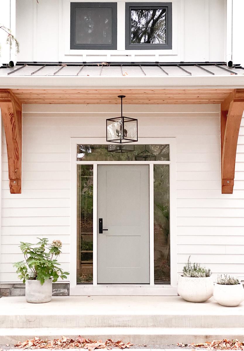
ENTRANCE ENTRANCE + DOG
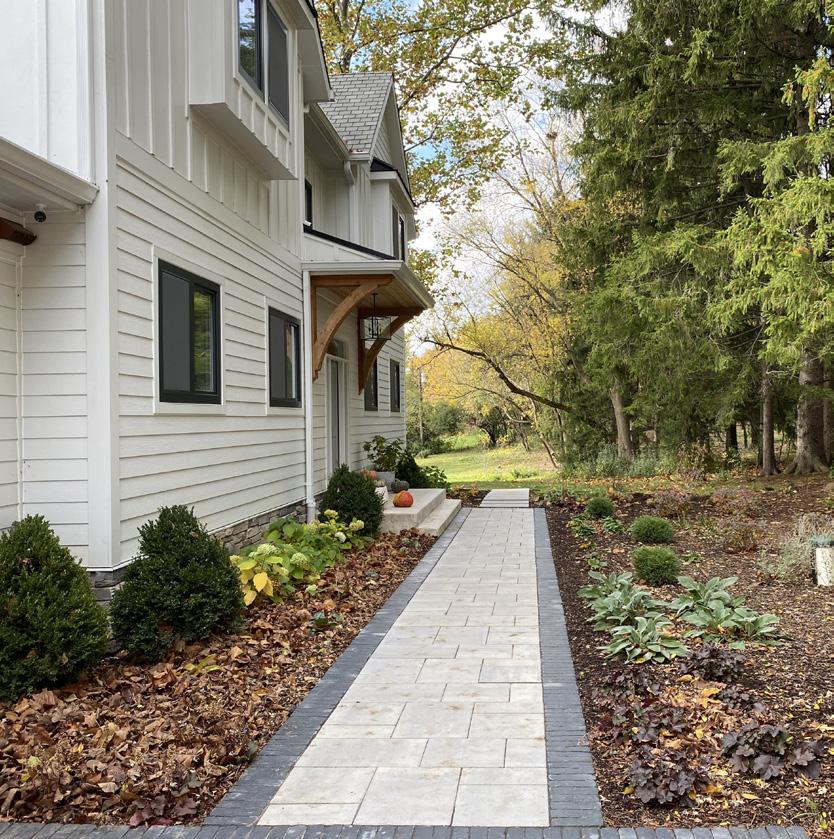
FRONT WALKWAY
REAR DECK
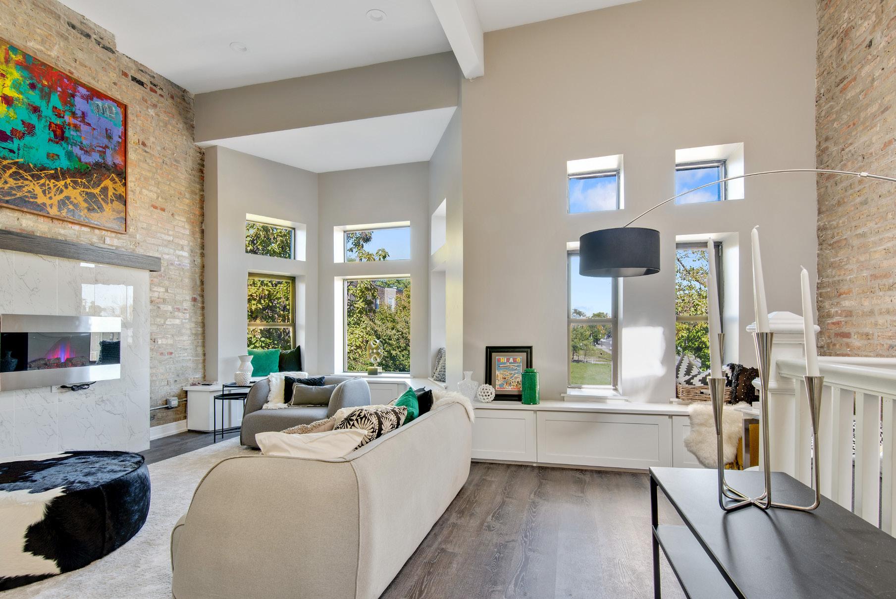
adams residence
interior alteration
An existing 2-flat building was converted in to a single family residence. After years of deterioration, the building needed an extensive amount of work.
first floor was opened up for a living, dining, kitchen space. two bedrooms in the rear.
second floor has 12 ft ceilings, with a open den area.
large primary suite in the rear, with 2 additional bedrooms.
basement was finished as an entertainment area + 1 additional bedroom.
26
04
SECOND FLOOR DEN / STUDY SPACE
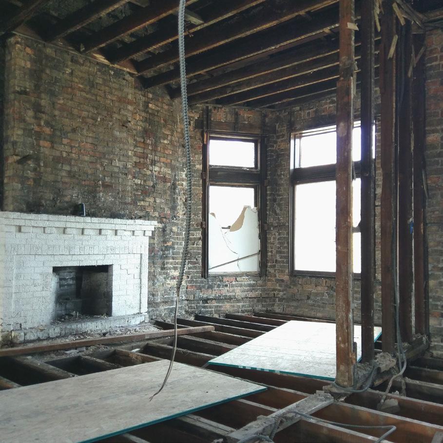
EXISTING CONDITION
Site visit during demolition. The interior was stripped down to the main structure.
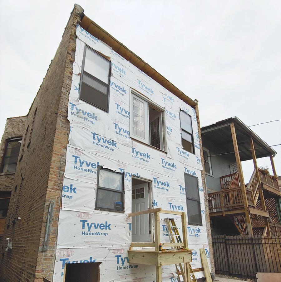
CONSTRUCTION PROGRESS
The existing rear wall was removed and rebuilt due to its deteriorated conditions.
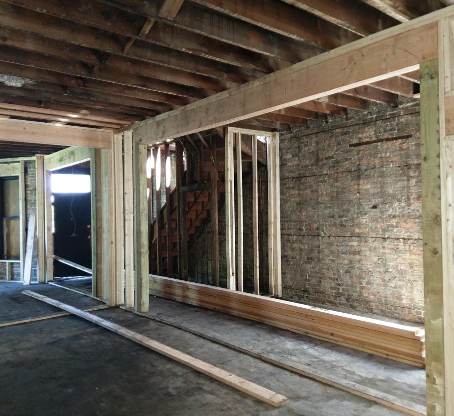
STRUCTURAL
New beams were introduced in place of the existing bearing walls to achieve the desired program and plan flow.
27 chicago, illinois | 2017-2018
04 adams residence interior
alteration
28
UP FD WH UP EXISTING 8" X 8.5" TIMBER BEAM (ABOVE) EXISTING FLOOR DRAIN 735 SF REC ROOM 19 SF CL 95 SF STORAGE 104 SF BATHROOM #1 37 SF MECH 149 SF BEDROOM #1 15 SF CL EXISTING STAIRCASE TO REMAIN F1 F1 F1 F1 3A 3A 3A EXISTIN TIMBER COLUMN EXISTIN TIMBER COLUMN F1 D008 D004 D005 D002 D003 D001 (3'-0" MIN) 3' 4" 163 SF CORRIDOR D006 2 A4 6' 2 1/4" 2' 6" 8' 0 1/4" 15'3 1/4" 4' - 5" 4'0" 12' 7 1/4" 19' 9" 37' 7 1/4" 14'1 3/4" 9' 4" 3' - 10" 6' 0 1/2" 4'0" 22' 6 1/2" PLAN NORTH description: c o n s u t a n t s : g e n e r a l n o t e s Firmin S. Senga SENGA ARCHITECTS 355 N Laflin Street #206 Chicago Illinois 60607 C:773 656 8946 fsengas@sengaarch.com CONTROL OVER THE CHARGE OF ACTS OR OMISSIONS OF THE CONTRACTOR, SUB-CONTRACTOR OR THEIR AGENTS OR EMPLOYEES OR ANY OTHER PERSONS PERFORMING PORTIONS OF THE WORK. THE ARCHITECT SHALL NOT BE "IN-CHARGE" OF THE WORK AS THE TERM IN DEFINED IN THE DISTRIBUTION TO UNAUTHORIZED PERSONNEL OR CONSTRUCTION OF THE STRUCTURE DEPICTED HEREIN W ITHOUT EXPRESS WRITTEN CONSENT OF SENGAARCHITECTS WOULD CONSTITUTE INFRINGEMENT OF SENGAARCHITECTS INC.THE RECIPIENT OF THIS DRAW ING ACKNOWLEDGES AND AGREES WWW.SENGAARCH.COM ISSUED FOR REVDATE Project Drawn by: Checked by: Project number: A2 PLANS 3403 W ADAMS ST, CHICAGO, IL 60624 SA.17.148 Author Checker SCALE: 1/4" = 1'-0" A2 BASEMENT -PLAN 1 ISSUED FOR PERMIT 102/09/2018 UP UP DN W EXISTING FIREPLACE 128 SF BEDROOM #2 90 SF MUDROOM 98 SF BEDROOM #3 375 SF KITCHEN 181 SF LIVING ROOM 123 SF DINING ROOM 65 SF TLT 10 SF CL 9 SF CL 8 SF CL DN 15 SF PANTRY DN 6A 3A 3A 6A E4 NEW EXTERIOR WALL F1 NEW RETURN SHAFT 3 A4 68 SF ENTRANCE D101 D102 D104 D103 D105 D108 D106 D107 9' - 1 3/4" 2' 0" 4' - 1 1/4" HEADER 9' 3" HEADER 9' - 11" HEADER 15'3" 14' 1" 8' - 4 1/2" 3' 5 1/4" 9' 7 1/4" 12' 11 3/4" 4' - 2 1/2" 4' - 4 1/2" 15' 1 1/2" 2'0" 9' - 1 3/4" 13' 11 3/4" 5' 0" 5' 8 1/4" 4'0" 7' 0" 4' 0" 2'1" 2' 1" 3' 6" 3' 0" 11' 7 1/4" 5' - 0" EXISTING FIREPLACE SKYLIGHT ABOVE 42 SF WIC 258 SF MASTER BEDROOM 19 SF CL 82 SF BATHROOM #3 20 SF CL 110 SF BEDROOM #5 112 SF BEDROOM #4 248 SF STUDY ROOM/LIBRARY 9 SF CL 115 SF MASTER BATHROOM 130 SF CORRIDOR WOOD PORCH BELOW FURNACE SHELVING BENCH SHELVING 59 SF OFFICE 6A 6A 3A 6A 3A 3A 3A 6A D201 D202 D204 D205 D203 D206 D207 D208 D209 D210 8'10" 19' - 8" 16'6 1/2" ALIGN ALIGN 2'0" 4' - 9 3/4" 7' - 11 1/2" 9' - 2 1/4" 12'4" 5' - 9 1/2" 3' 4 1/2" 9' - 2 1/4" 3' - 6" 6' 1 3/4" 3' - 4" 6' - 2 1/2" 11' 8 3/4" 7'2 1/2" 4' - 11" 8' 6 1/4" 3' 6" 11' 9 1/4" 3'0" 2' 5" 2' 10" SHELVING 19' - 3 3/4" JULIET BALCONY E4 NEW EXTERIOR WALL 8' 9 3/4" 13'6 1/4" 3' 6 1/4" 5' 4 1/2" ARCHITECT'S NOTE: ARCHITECT ASSUMES NO RESPONSIBILITY FOR ANY DISCREPANCY BETWEEN THESE DRAWINGS AND THE CONSTRUCTION CONTRACT ARCHITECT SHALL NOT HAVE CONTROL OVER OR CHARGE OF AND SHALL NOT BE RESPONSIBLE FOR CONSTRUCTION MEANS, METHODS, TECHNIQUES SEQUENCING OR PROCEDURES, OR FOR THE SAFETY PRECAUTIONS AND PROGRAMS IN CONNECTION WITH THE WORK OF THE CONSTRUCTION CONTRACT("WORK"). THE ARCHITECT SHALL NOT HAVE CONTROL OVER THE CHARGE OF ACTS OR OMISSIONS ILLINOIS STRUCTURAL ACT. THE ARCHITECT SHALL NOT BE HELD RESPONSIBLE FOR ERRORS AND/OR MISTAKES MADE DURING CONSTRUCTION BY THE CONTRACTOR. THE OWNERS' SOLE REMEDY FOR CONSTRUCTION DEFECTS, ERRORS OR OMISSIONS SHALL BE AGAINST THE CONTRACTOR.THIS DRAWING IS THE SOLE PROPERTY OF SENGAARCHITECTS AND IS PROTECTED UNDER US COPYRIGHT LAW AND ARCHITECTURAL WORKS PROTECTION ACT OF 1990.THE COPY OF THIS DRAWING AND OR DISTRIBUTION TO UNAUTHORIZED PERSONNEL OR CONSTRUCTION THAT THE OWNERSHIP OF THE DRAWING AND ALL OTHER RIGHT, TITLE, AND INTEREST THEREIN, INCLUDING WITHOUT LIMITATION, ALL RIGHTS UNDER US COPYRIGHT AND OTHER INTELLECTUAL PROPERTY LAW, ARE RETAINED BY SENGAARCHITECTS (C) 2016 SCALE: 1/4" = 1'-0" A2 FIRST FLOOR -PLAN 2 SCALE: 1/4" = 1'-0" A2 SECOND FLOOR -PLAN 3 BASEMENT - PLAN FIRST FLOOR - PLAN
29 DN W EXISTING FIREPLACE 3 A4 EXISTING FIREPLACE SKYLIGHT ABOVE 42 SF WIC 258 SF MASTER BEDROOM 19 SF CL 82 SF BATHROOM #3 20 SF CL 110 SF BEDROOM #5 112 SF BEDROOM #4 248 SF STUDY ROOM/LIBRARY 9 SF CL 115 SF MASTER BATHROOM 130 SF CORRIDOR WOOD PORCH BELOW FURNACE SHELVING BENCH SHELVING 59 SF OFFICE 6A 6A 3A 6A 3A 3A 3A 6A D201 D202 D204 D205 D203 D206 D207 D208 D209 D210 8'10" 19' 8" 16'6 1/2" ALIGN ALIGN 2'0" 4' - 9 3/4" 7' - 11 1/2" 9' - 2 1/4" 12'4" 5' 9 1/2" 3' 4 1/2" 9' - 2 1/4" 3' - 6" 6' 1 3/4" 3' - 4" 6' 2 1/2" 11' 8 3/4" 7'2 1/2" 4' 11" 8' 6 1/4" 3' - 6" 11' 9 1/4" 3'0" 2' 5" 2' 10" SHELVING 19' - 3 3/4" JULIET BALCONY E4 NEW EXTERIOR WALL 8' 9 3/4" 13'6 1/4" 3' 6 1/4" 5' 4 1/2" ARCHITECT ASSUMES NO RESPONSIBILITY FOR ANY DISCREPANCY BETWEEN THESE DRAWINGS AND THE CONSTRUCTION CONTRACT ARCHITECT SHALL NOT HAVE CONTROL OVER OR CHARGE OF AND SHALL NOT BE RESPONSIBLE FOR CONSTRUCTION MEANS, METHODS, TECHNIQUES SEQUENCING OR PROCEDURES, OR FOR THE SAFETY PRECAUTION E CHARGE OF ACTS OR OMISSIONS OF THE CONTRACTOR, SUB-CONTRACTOR OR THEIR AGENTS ACT. THE ARCHITECT SHALL NOT BE HELD RESPONSIBLE FOR ERRORS AND/OR MISTAKES MADE DURING CONSTRUCTION BY THE CONTRACTOR. THE OWNERS' SOLE REMEDY FOR CONSTRUCTION DEFECTS, ERRORS OR OMISSIONS SHALL BE AGAINST THE CONTRACTOR.THIS DRAWING IS THE SOLE PROPERTY OF SENGAARCHITECTS AND IS PROT UNAUTHORIZED PERSONNEL OR CONSTRUCTION OF THE STRUCTURE DEPICTED HEREIN W ITHOUT OF THE DRAWING AND ALL OTHER RIGHT, TITLE, AND INTEREST THEREIN, INCLUDING WITHOUT LIMITATION, ALL RIGHTS UNDER US COPYRIGHT AND OTHER INTELLECTUAL PROPERTY LAW, ARE RETAINED BY SENGAARCHITECTS (C) 2016 A2 1 SCALE: 1/4" = 1'-0" A2 SECOND FLOOR -PLAN 3 SECOND FLOOR - PLAN
05
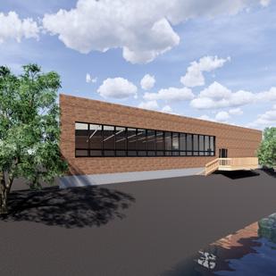
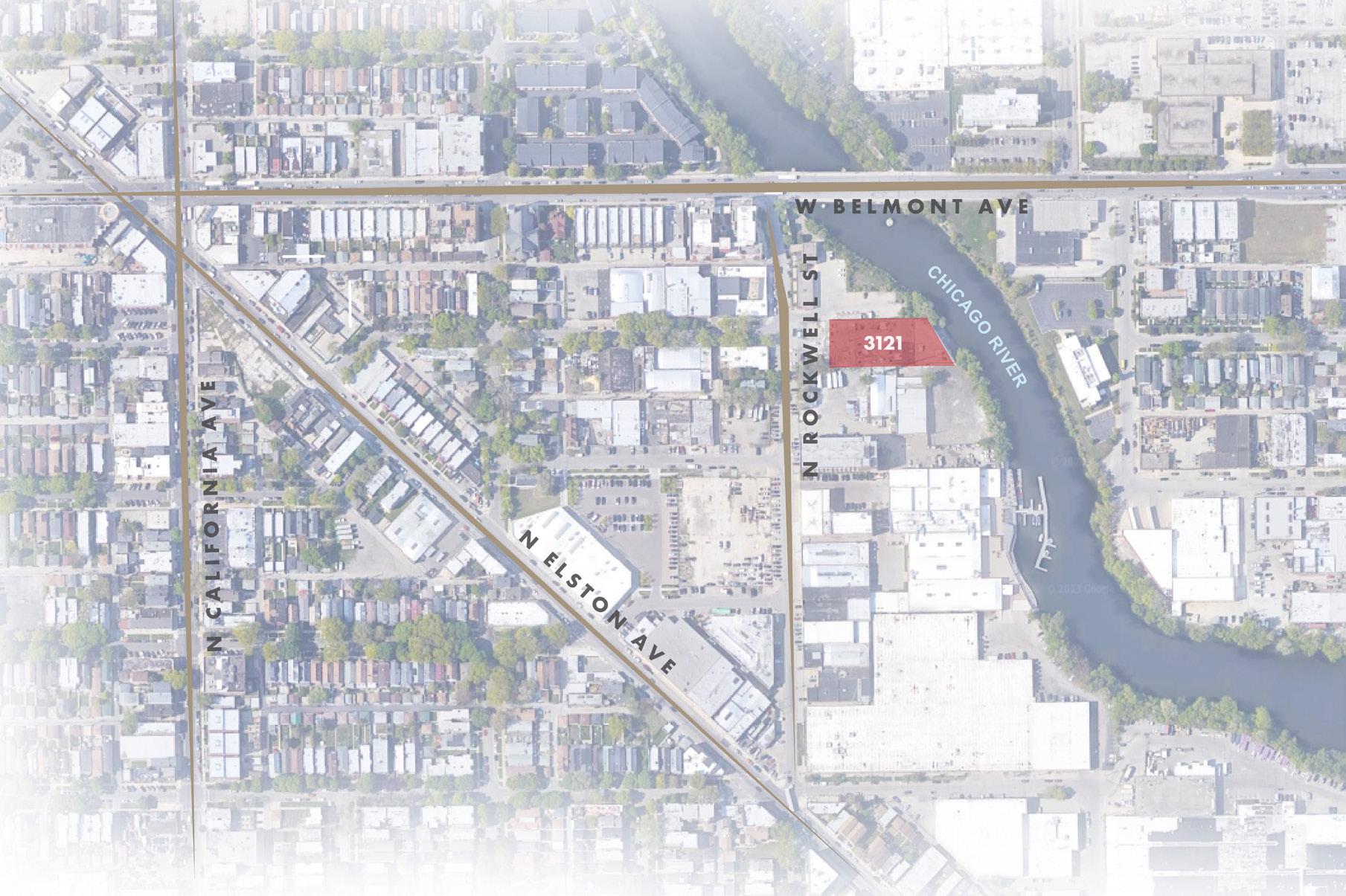
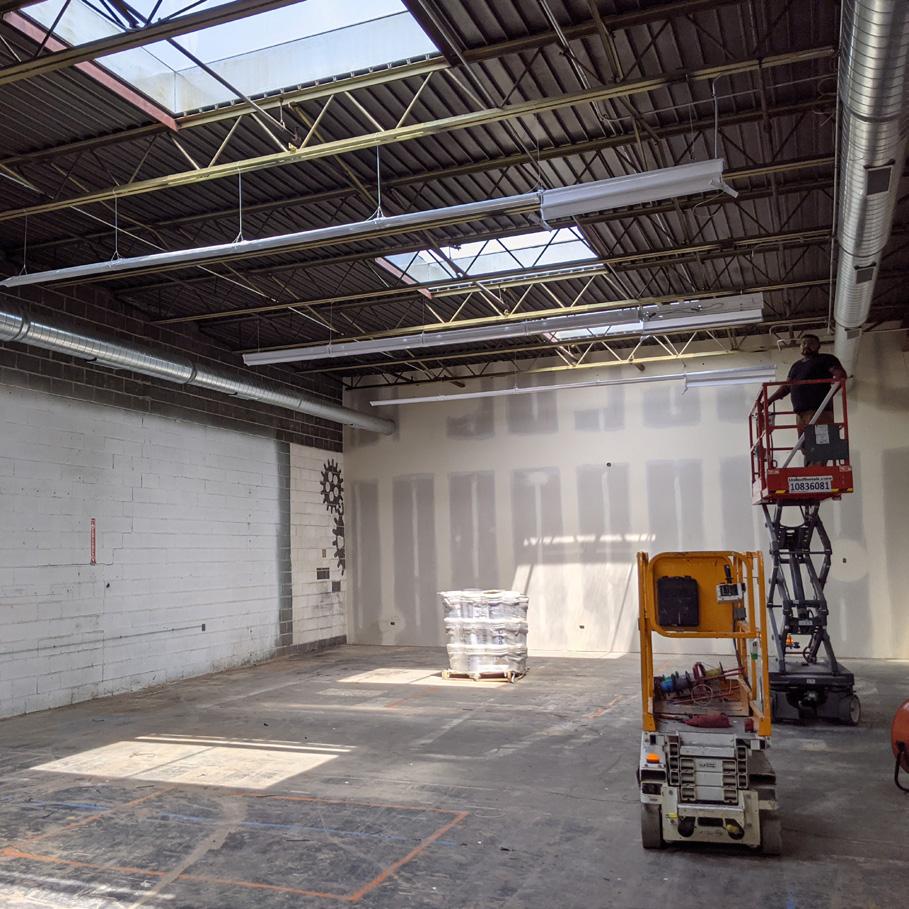
visceral dance studio warehouse conversion
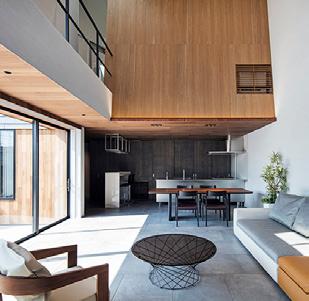
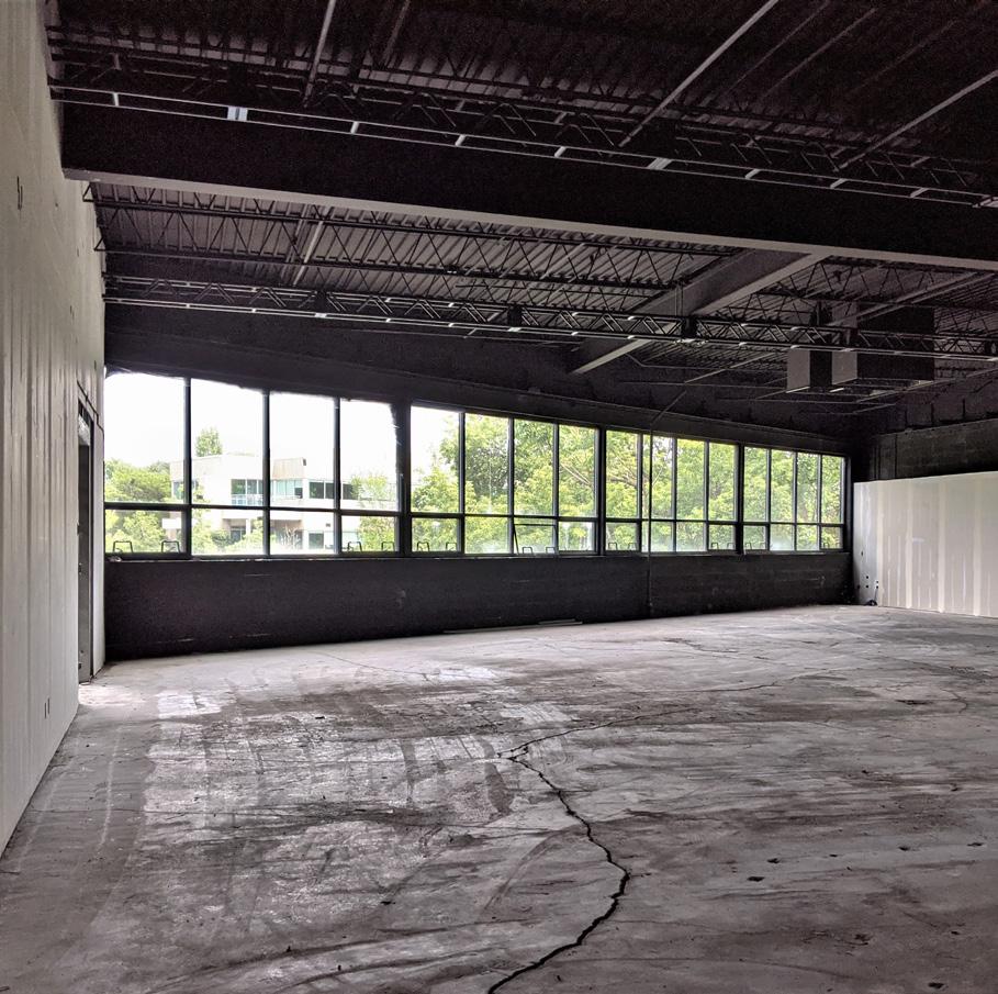
We closely worked with the founder of a Dance Studio on the design of their new location. The space was designed inside of an existing warehouse building along the north branch of the Chicago River.
His vision was to have the main space for performances and events, with large windows that look over the river. The main studio space would be one of the six total studios - an upgrade from his previous three studio space.
30
SITE PLAN
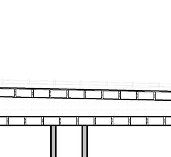
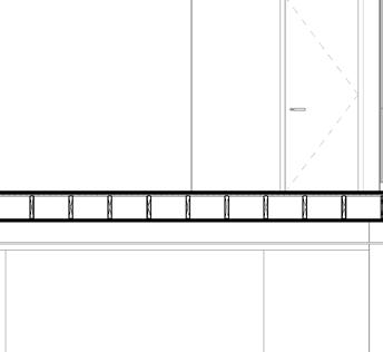
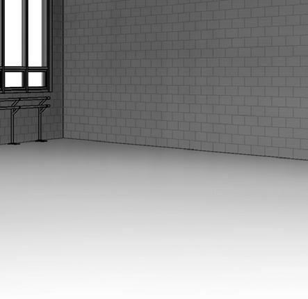
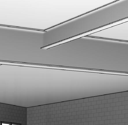
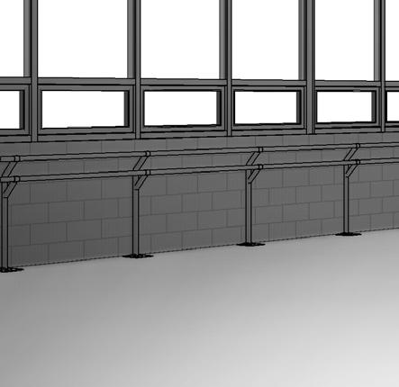
The rear exterior wall facing the Chicago River was rebuilt. New windows were placed that allowed for a panoramic view of the river.
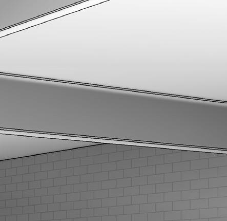
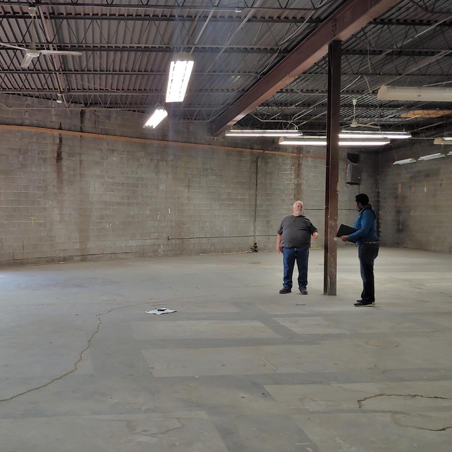
A single, obstructive column at midspan of the roof rafters was removed, with the introduction of a new steel beam. This solution ended up being more cost effective than re-framing a new roof over this portion of the building.


31 chicago, illinois | 2019
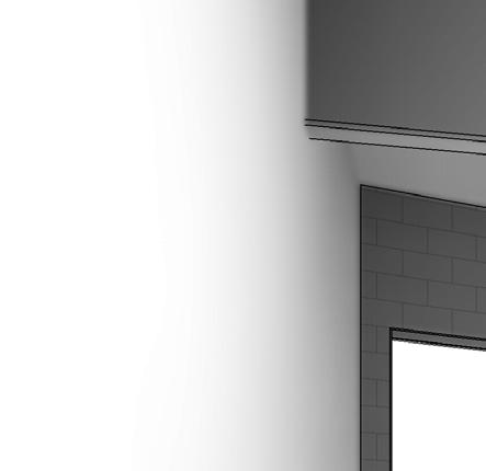
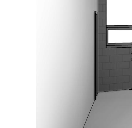
MAIN STUDIO - FACING THE RIVER
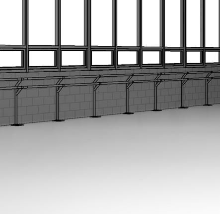
OBSTRUCTING COLUMN TO BE REMOVED
05 dance studio - chicago river warehouse renovation
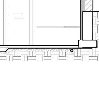
The existing column supported a W18 beam spanning E-W, which held up the existing roof structure.
With replacement of the roof structure out of question, a solution was reached to hang the existing beam on a new W33 beam that clear spans the building.
32
REF. 1142 SF STORAGE 108 67' 3" 2198 SF STUDIO #2 106 6' - 0" 28' 4" 55' 5 3/4" 31' 9" 34' 1 1/2" 10' 0" 18' 0" 38' 2" 37' 3/4" 2178 SF STUDIO #1 105 1572 SF STUDIO #3 119 1188 SF STUDIO #4 117 1882 SF STUDIO #5 116 463 SF STORAGE 112 477 SF STORAGE 111 61 SF STORAGE 107 427 CORRIDOR 718 SF LOUNGE 113 588 SF STRETCHING 118 2047 SF CORRIDOR 120 338 SF MEN LOCKER 104 582 SF WOMEN LOCKER 103 86 SF FURNACE 136 540 SF MECH ROOM 135 174 SF OFFICE 129 117 SF OFFICE 128 23 SF TLT 126 22 SF TLT 127 330 SF OFFICE 123 196 SF OFFICE 124 234 SF OPEN OFFICE 125 314 SF LOBBY 131 210 SF MEN 133 254 SF WOMEN 132 296 SF RETAIL 130 visceraldance LOGO ON THE WALL 55 SF AG TLT 102 NEW 80"X80" SKYLIGHT 59 SF AG TLT 115 34' 2 3/4" 12' 0" 4' - 1 1/2" 4' 3" 32' 9" 37' 9" 16' 4" 15' 10" 21' 7 1/2" A6 1 2 6' - 2" COL. COL. COL. 3' 11 1/2" 32' 1/4" COL. COL. 6' - 0" 29' 9" 33' 4 1/4" 43' - 5" 24' - 11" NEW DF 9' 1/2" 8' 0" 9' 3/4" STEP 4' 5 1/2" 8' 0 1/2" NEW STL 7' 5" 12' 0" 28' 4" 12' 0" 7' 6" 18' - 4 1/2" 11' 0" 27' 5" 29' 11 3/4" 25' 11" 2 A5 8A 9' 6 3/4" 6' 6" 9' 6 3/4" 28' 1 3/4" 57 SF STORAGE 114 REFER TO SHEET A6 FOR GLASS DOOR/WINDOW DETAILS, TYP. 8A 66' 7 1/2" BLACK MARLEY FLOOR BLACK MARLEY FLOOR BLACK MARLEY FLOOR BLACK MARLEY FLOOR BLACK MARLEY FLOOR DARK GRAY CARPET POLISHED CONCRETE BLACK MARLEY FLOOR POLISHED CONCRETE POLISHED CONCRETE POLISHED CONCRETE 6A2 ALIGN 11' - 7" 9" 3 A5 1' 5" 825 SF WAITING ROOM 101 1 A5 6A2 8 A5 7' 10 1/4" 3A 10' 9 1/2" 2' 1 1/2" 10' 1" 6A2 6A2 8A 6A2 6A2 6A2 6A 6A 6A 3A D102 D105 D106 D104 D107 D108 D109 D110 D111 D112 D116 D117 D118 D120 D119 10' 5 1/2" D121 D122 D125 D124 D126 D127 6' - 0" 2' - 0" 3' - 0" 12' 6" 3' - 10 1/2" 24' 0" 3' - 10 1/2" NEW STEEL STAIRS TO MECH. AREA (ABOVE STORAGE) 6A2 D031 237 SF COORRIDOR 137 2047 SF CORRIDOR 120 PROVIDE MIN 20% ACCESSIBLE LOCKER PROVIDE MIN 20% ACCESSIBLE LOCKER D135 D136 D137 E4 E4 3A E4 E4 E4 E4 E4 E4 E4 E4 E4 D139 231 SF CORR. 138 D100 D101 REFER TO SHEET A6 FOR GLASS DOOR/WINDOW DETAILS, TYP. REFER TO SHEET A6 FOR GLASS DOOR/WINDOW DETAILS, TYP. REFER TO SHEET A6 FOR GLASS DOOR/WINDOW DETAILS, TYP. NEW 80"X80" SKYLIGHT NEW 80"X80" SKYLIGHT NEW 80"X80" SKYLIGHT NEW 80"X80" SKYLIGHT 5' - 10 1/4" 12' 0" 26' - 0 3/4" 12' - 0" 10' 8 1/2" NEW 80"X80" SKYLIGHT NEW 80"X80" SKYLIGHT NEW 80"X80" SKYLIGHT NEW 80"X80" SKYLIGHT NEW 80"X80" SKYLIGHT NEW 80"X80" SKYLIGHT NEW 80"X80" SKYLIGHT NEW 80"X80" SKYLIGHT
FLOOR PLAN
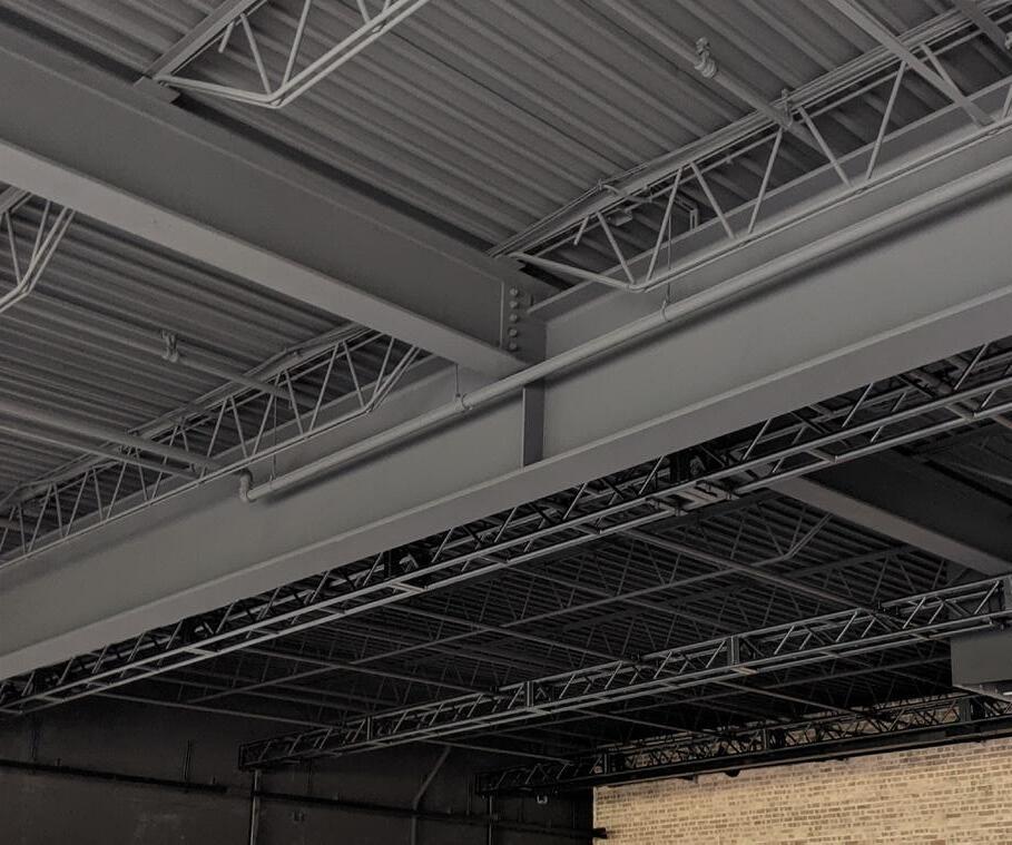
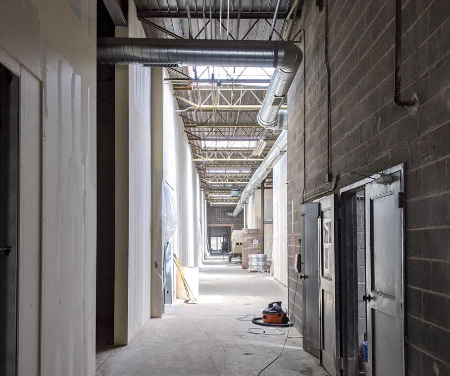
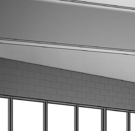
33 MAIN STUDIO NEW STEEL BEAM SKYLIGHTS IN STUDIO UP 8'5 1/4" 4057 SF STUDIO #6 110 427 SF CORRIDOR 109 NEW STEEL BEAM ABOVE A6 3 COL. 56' 6 1/2" 37' 1 3/4" 3' - 11 1/2" STL COLUMN DEMO EX. FOOTING, ENLARGE 64' 6" E1 6A2 D113 D114 A4 1 NEW MASONRY WALL NEWWNDOWS 640
34
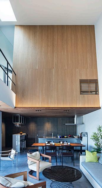
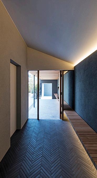
ROOM - KITCHEN
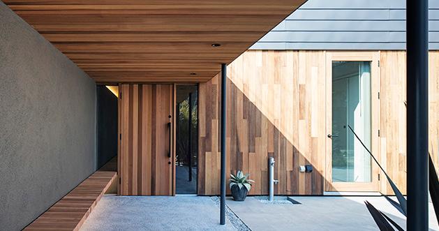
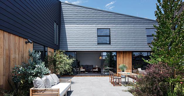
COVERED ENTRANCE LIVING
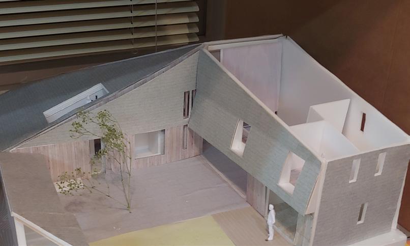
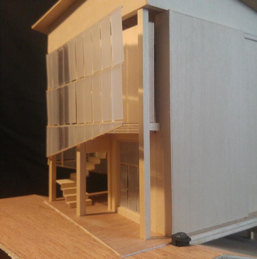
During the summer internship in Tokyo, good portion of the time was spent on fabricating physical models for client presentations. Working closely under the principal played an important role in communicating details and design intent. Through many iterations, it was a very critical experience to understand process of design development.
35 06 oo house model study | internship fukuoka, japan | 2016-2017
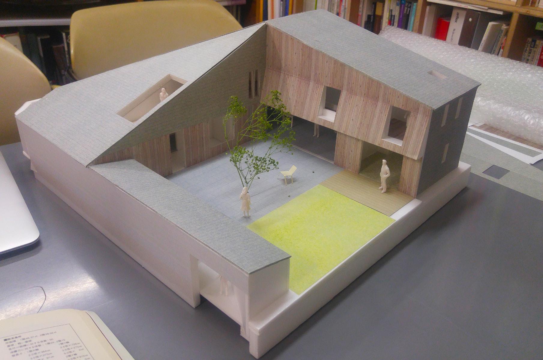
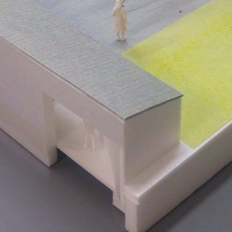
Exterior Entrance studied materiality and path to provide a scenic route to the entrance overlooking the courtyard
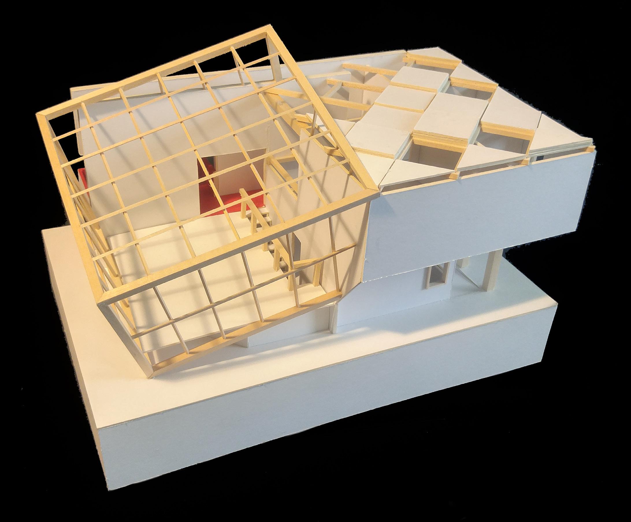
Material Study
composition of metal and wood exterior siding
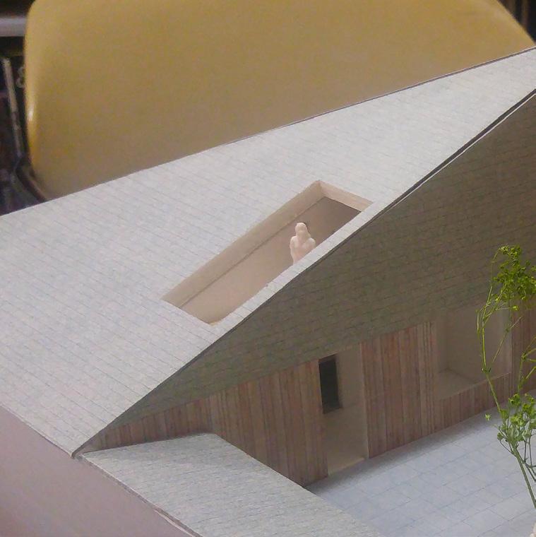
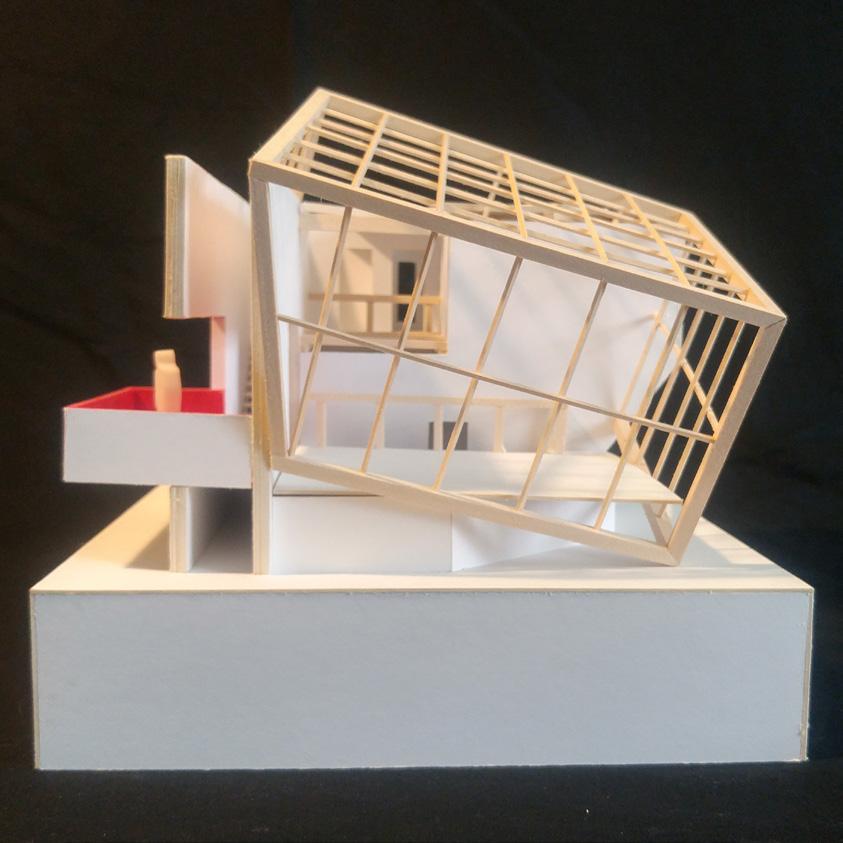
Detail
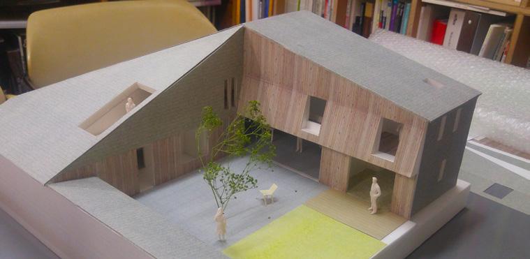
cutout created a small walk-out balcony without compromising on the roof profile.
36
COVERED ENTRANCE
37
COURTYARD
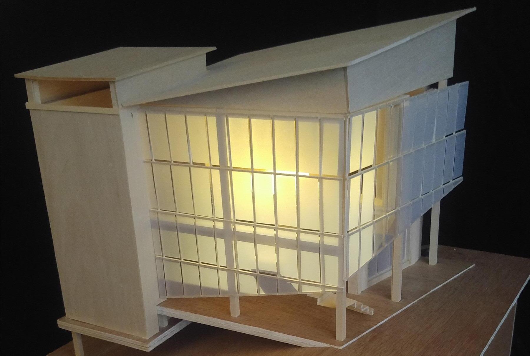
Univerity Project Models
Two residential proejcts that explores programming (Left) and massing + structural grid (right)
38 06
academic work model studies
39 2013-2017
projects
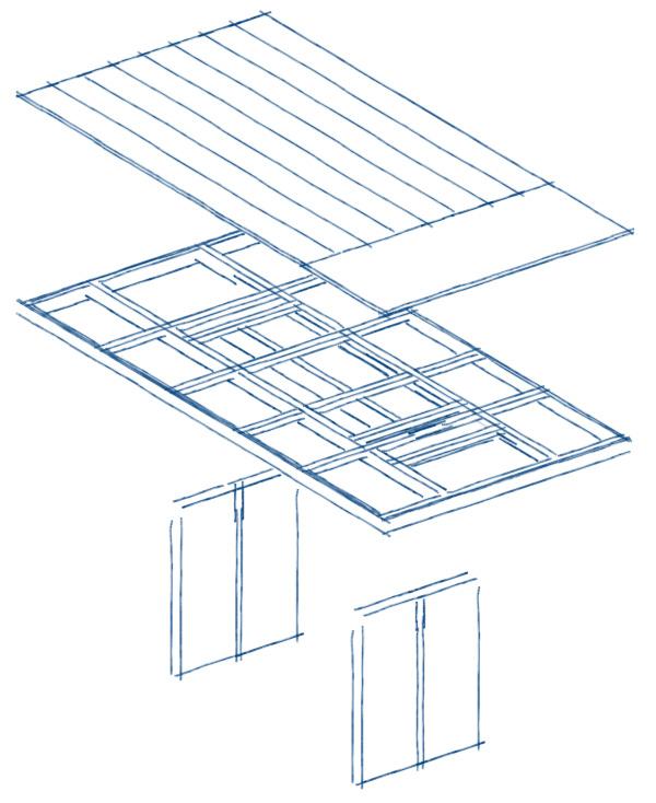
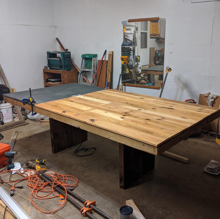
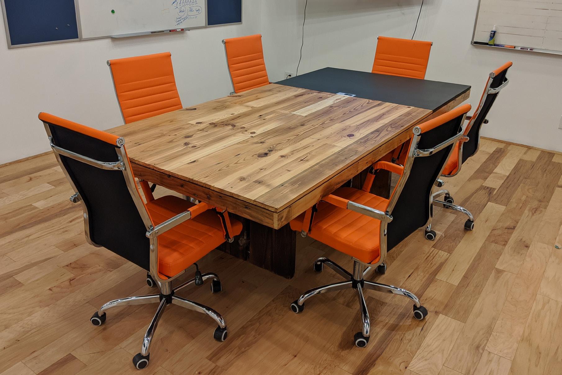
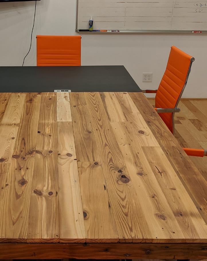
conference table
Once a part of a small architectural team, I was given the opportunity to design and build a 8 ft x 4 ft conference table for our new office space. To ensure ample legroom, two 6 ft steel angles reinforced the table top, allowing for additional overhang.
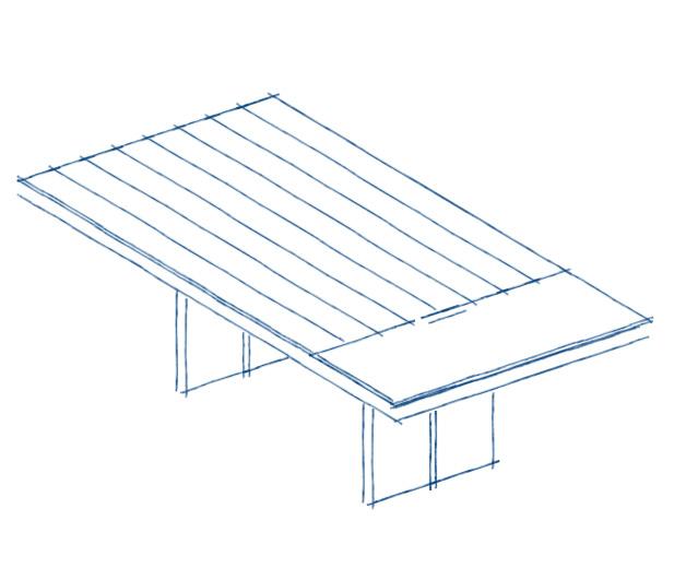
Materials: reclaimed wood +painted mdf
40
07 personal
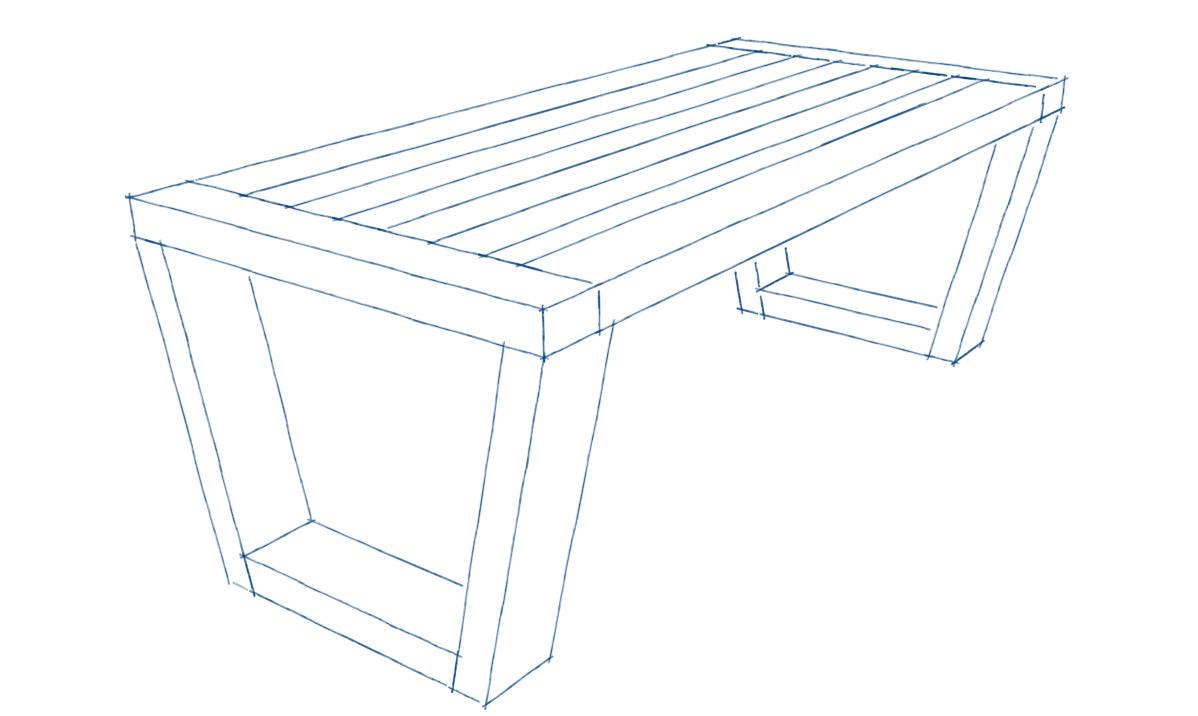
conference table EXPLODED PERSPECTIVE
41 2020
07 personal projects
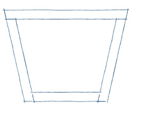
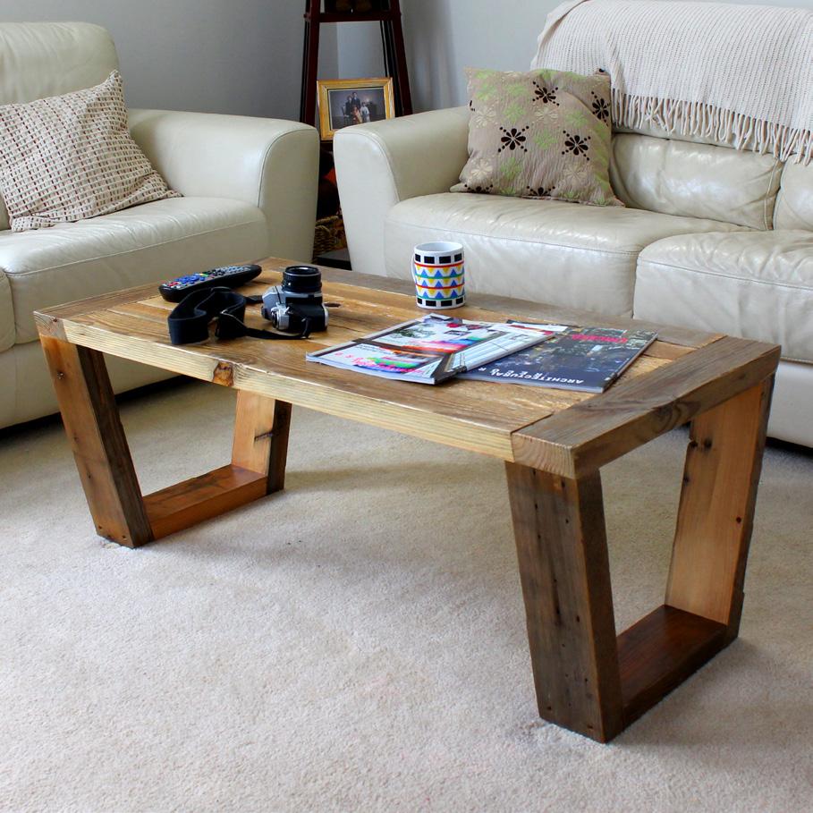
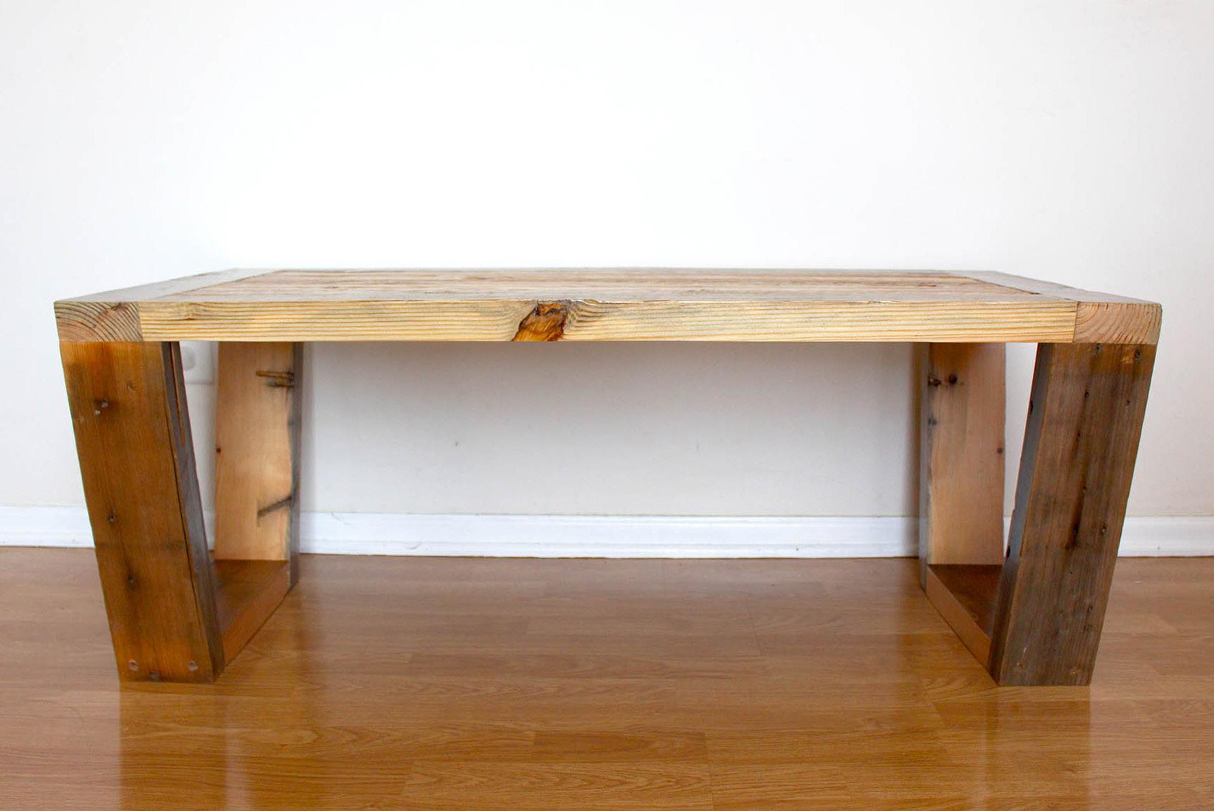
reclaimed wood coffee table
PERSPECTIVE
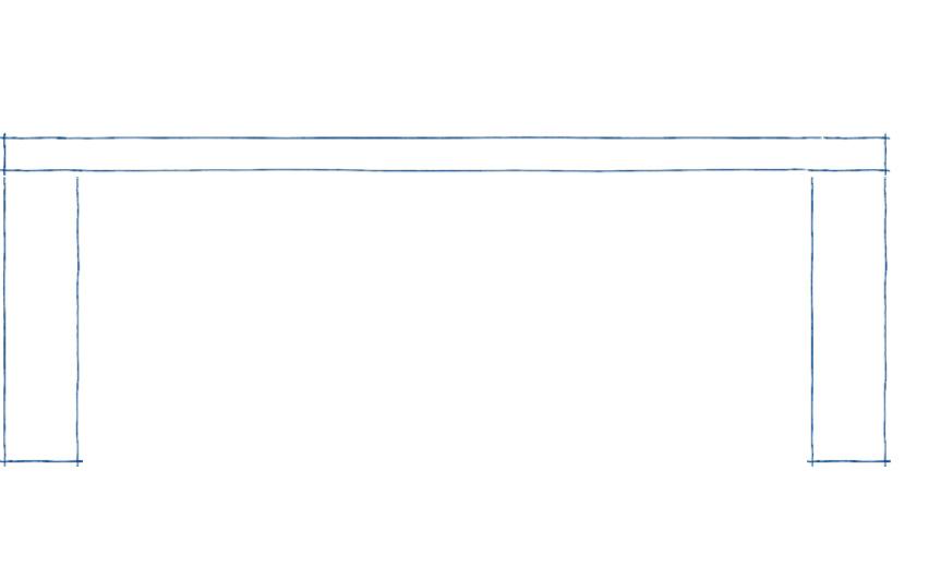
SIDE VIEW FRONT VIEW
42
table
Using scrap pieces of reclaimed lumber, this piece was designed to have a mid-century modern appearance. To give a light weight feel, the legs were given a reverse trapezoidal shape, with the table top edge following the same beveled angle.
43 2017
coffee
PERSPECTIVE
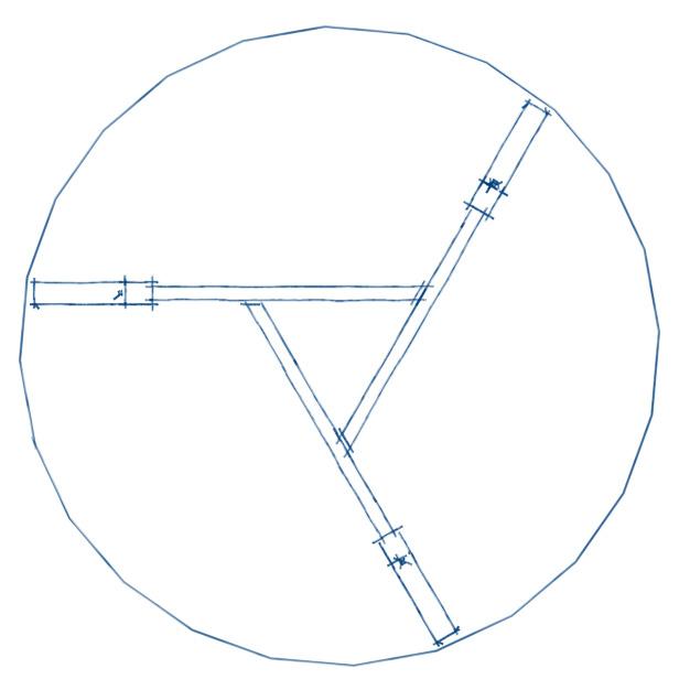
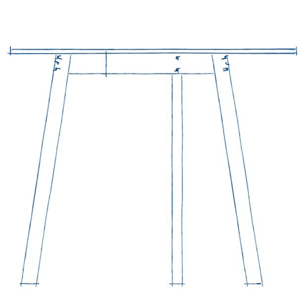
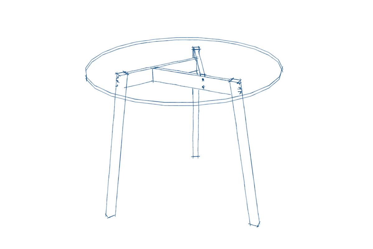
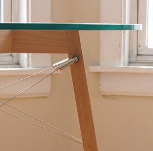
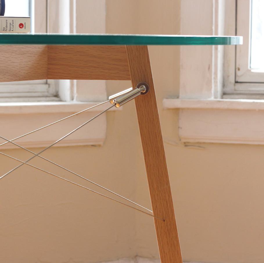
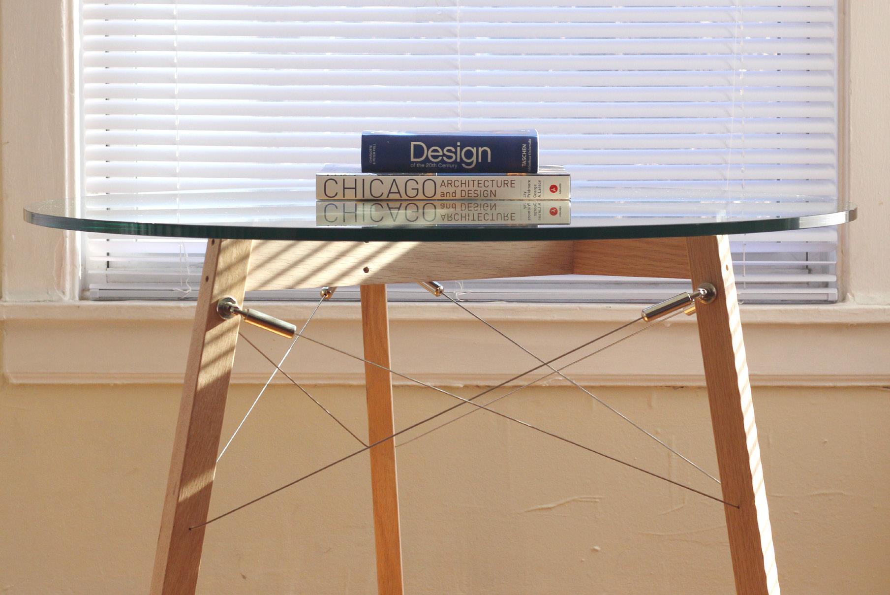
44 07 personal projects glass + oak table
SIDE VIEW TOP VIEW
glass + oak dining table
Having picked up a 36” glass top from an antique store, there was a need for a base for a table. My attempt to create a slender table base faced with challenges in the stability of bearing the heavy glass top. Stainless steel tension cables were added to brace the 3 legs + minimizing the torsion.
45 2021

RYO MIZUKI ARCHITECTURAL DESIGNER ryo_mizuki@yahoo.com (847)239-4535 Thank you!