
Ryan Helle // Assoc. AIA. // M.Arch // ryanhelle@gmail.com // 720-544-1021
EXPERIENCE Project Architect - Project Manager // Roth Sheppard Architects
5.5 years //June 2018 - December 2023 // Denver, CO
As Project Manager:
• Lead Construction Administration for three ground-up VA outpatient clinics across the country
• Lead a multi-faceted project team for the programmatic and schematic design of a 17,000sf Net-Zero Rescue Facility
• Lead all phases of design (SD-CA) for a multi-phased, highly technical Federal project (Project details under an NDA)
As Project Architect:
• Coordinated technical drawing efforts with consultants and engineers
• Drafted coherent, professional Contract Documents for 15+ projects
• Coordinated and selected materials for interior furnishings
• Designed, detailed, and coordinated exterior assemblies
• Coordinated complete design packages through multiple phases of design (Programming, SD, DD, CD)
• Performed comprehensive code analysis on a variety of project types and locales
• Lead sustainability accreditations for Green Globes projects
• Championed and led RSA's commitment to the AIA 2030 goal
• Robust experience in construction administration for projects of varying sizes, locations, and typologies
Research Assistant + Student // ColoradoBuildingWorkshop
June 2017 - December 2017 // Denver, CO
As a student:
• Collaborated with classmates to assemble a complete CD set, apply for permits, analyze local zoning and building code regulations
• Worked both on-site and off-site to prefabricate and construct a 2000 sq-ft canopy, set form-work, assisted pouring of a 40’ long concrete wall, as well as other construction tasks
As a Research Assistant:
• Assembled award submittal packages for Confluence Hall, producing professional publication drawings, diagrams, and overall graphic layout
Architectural Designer // Stantec ViBE
1.5 years //January 2015 - August 2016 // Boulder, CO
• Architectural Designer for a firm that specializes in commercial retail projects
• Understood client relationships, collaborated with consultants, and understood in-depth the SD-CD phases
RECOGNITION AIA Colorado // 2021 Firm of the Year - Roth Sheppard Architects
Modern In Denver, Winter 2020 Publication // Kaffe Landskap
Modern In Denver, Winter 2017 Publication // Confluence Hall
2018 ACSA Design Build Award // Confluence Hall
2017 AIA Utah Honor Award // Confluence Hall
ArcDaily Top Design Build Projects of 2017 // Confluence Hall
Special Honors Graduate // University of Colorado Boulder
AIAS CU Boulder // First Place in Fabrication and Senior Studio 2014
EDUCATION
Master of Architecture
University of Colorado Denver // Aug 2016-May 2018
G.P.A 3.9
Design Build Certificate // ColoradoBuildingWorkshop
Confluence Hall // Jan 2017-June 2017
Next Stage Collaborative Gallery // Oct 2016-Dec 2016
Bachelors of Environmental Design // Emphasis in Architecture
University of Colorado Boulder // Aug 2010-May 2014
Danish Institute for Study Abroad // Copenhagen, Denmark // Jan 2012-June 2012
G.P.A 3.8
SKILLS Technical
• Revit, AutoCAD, Adobe Suite (AI, PS, ID), Microsoft Office, Rhinoceros, Sketchup, Vray, Physical Modeling, Sketching, AI imaging platforms
• Technical accuracy of drafting, detail development, renderings, graphic design and layouts
• Ability to decipher and coordinate zoning, building, energy, accessibility, and all other relevant codes to a project
• A solid understanding of standard architectural principles, construction methods, and building systems
• Ability to properly incorporate new building science and sustainable construction methodologies into all projects
• Familiarity with local building codes, zoning regulations, and AIA contract requirements
• Ability to develop, review, and document Project Specifications
• Ability to effectively perform and document Construction Administration tasks
Management
• Proficiency in developing comprehensive project plans for small to medium-sized projects, including defining scope, schedule, budget, and resources
• Ability to lead small project teams and communicate expected firm standards
• Experience in Excel, Ajera, and other Project Management software
• Completed Project Management training (PSMJ Certification)
• Ability to perform QA/QC reviews on personal and peer work, understanding the importance of quality control throughout all documents
• Experience in compiling fee estimates, drafting proposals, and contracts
Personal
• Understands the critical importance of maintaining positive client relations in all facets of the work
• Strong written and verbal communication skills for project documentation, reports, and presentations
• Ability to anticipate potential challenges and proactively address them
REFERENCES Avik K. Guha AIA, NCARB, NOMA, CDT // Colleague, Mentor & former Project Manager
Caitlin Zemljak AIA, NCARB // Colleague & former Project Manager
Joy Spatz AIA, NCIDQ, LEED AP // Colleague & Senior Project Manager
Mark McClelland Retired Architect // Colleague & Mentor
Contact Information available upon request
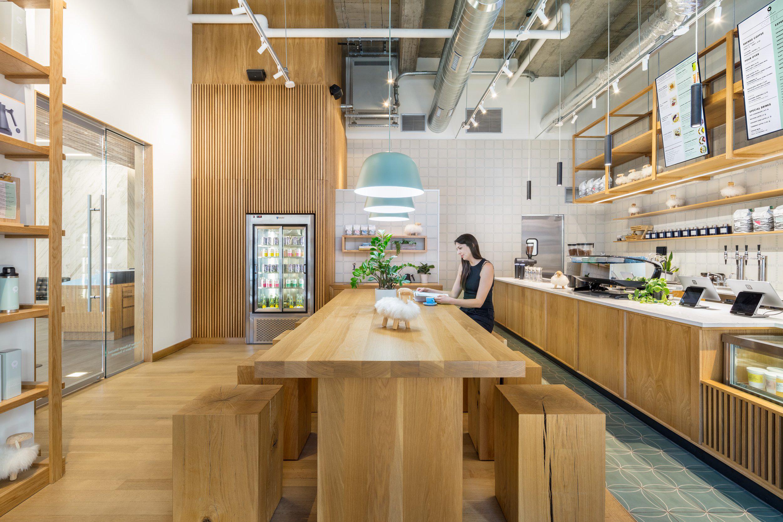
IKAFFE LANDSKAP
Proj. Type | Coffee and Bakery Retailer - Tenant Fit-Out // 944 SF
Location | 14th and Lawrence, Denver, CO
Date | December 2020
Lead Design | Adam Harding, Principal RSA
Professional Role | DD, CD, CA
Firm | Roth Sheppard Architects
Project Brief
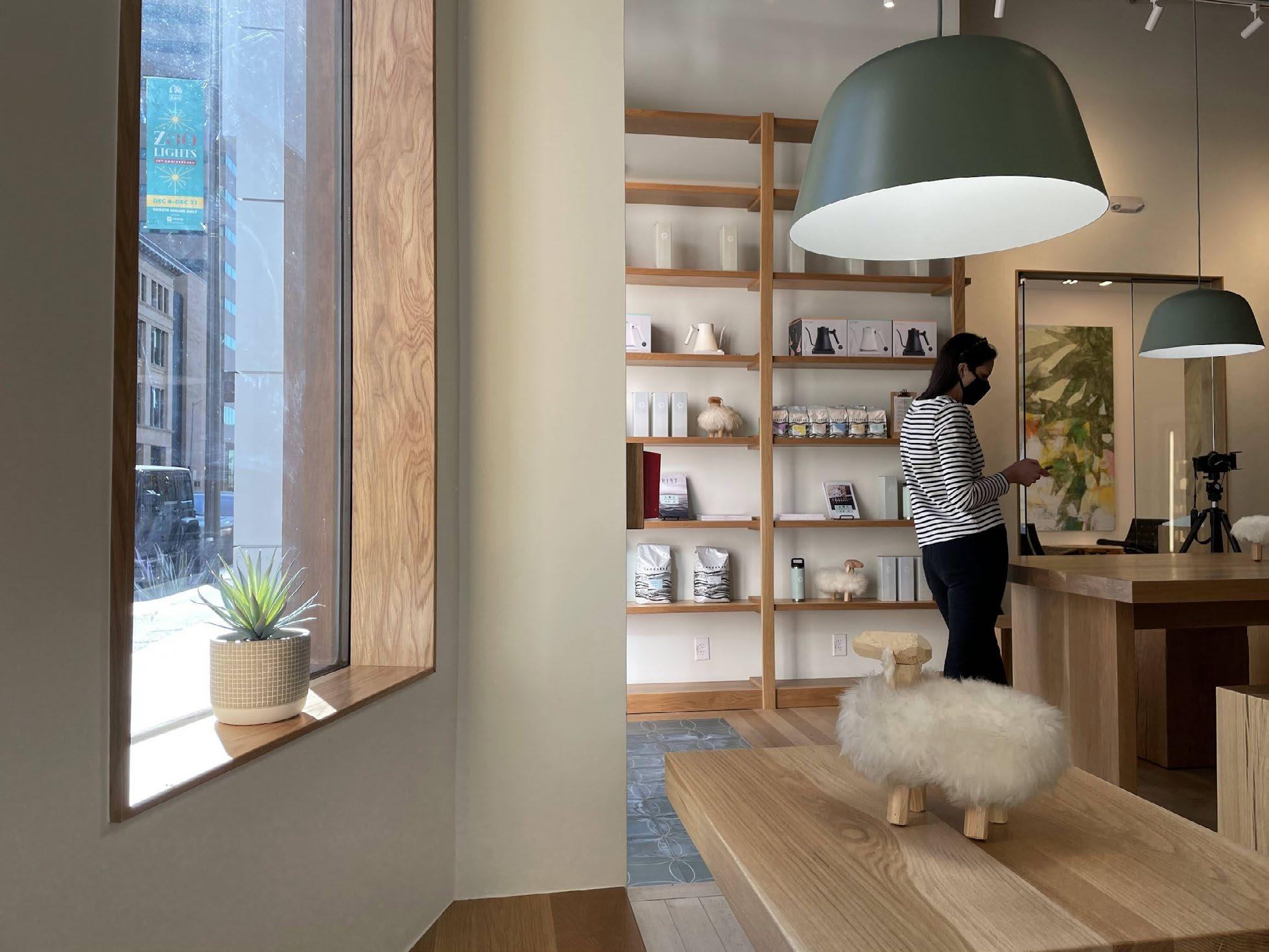
The Swedish words 'Kaffe' and 'Landskap' individually translate to 'coffee' and 'landscape.' Combined, they evoke the concept that this café is intricately linked to the surrounding environment. The ambiance at Kaffe Landskap embodies the spirit of Fika – a Swedish cultural ethos promoting moments of pause, enjoyment, and social interaction.
Kaffe Landskap's design aesthetic combines modern elements with a playful touch, employing a straightforward palette of materials to foster a feeling of warmth, comfort, and equilibrium—an ideal setting for Fika. The 1401 Lawrence location encapsulates the dynamic and cohesive urban environment, offering a distinctive space for respite.
The project was developed within a white-box space at the ground level of a Class A office tower. Custom detailing at the entrances and openings was incorporated to enhance thresholds and harmonize with the adjacent surroundings.
Individual Role
In my specific role, I was responsible for a variety of key tasks:
• Documenting a complete and coherent CD set
• Crafting custom details (threshold, trim, furniture) in collaboration with a local millworker
• Aiding in material selection
• Coordination with sub-consultants
• Overseeing the entirety of Construction Administration
• Negotiating detail choices between the Client and Owner of the Tenant space
Extensive on-site coordination with the GC and subcontractors was crucial to guarantee the meticulous execution of the details and to achieve material, furniture, and fixture alignments. Additionally, I played a role in the CA phase for the Flagship location at Union Station.
Coffee Bar
Oak Community Table
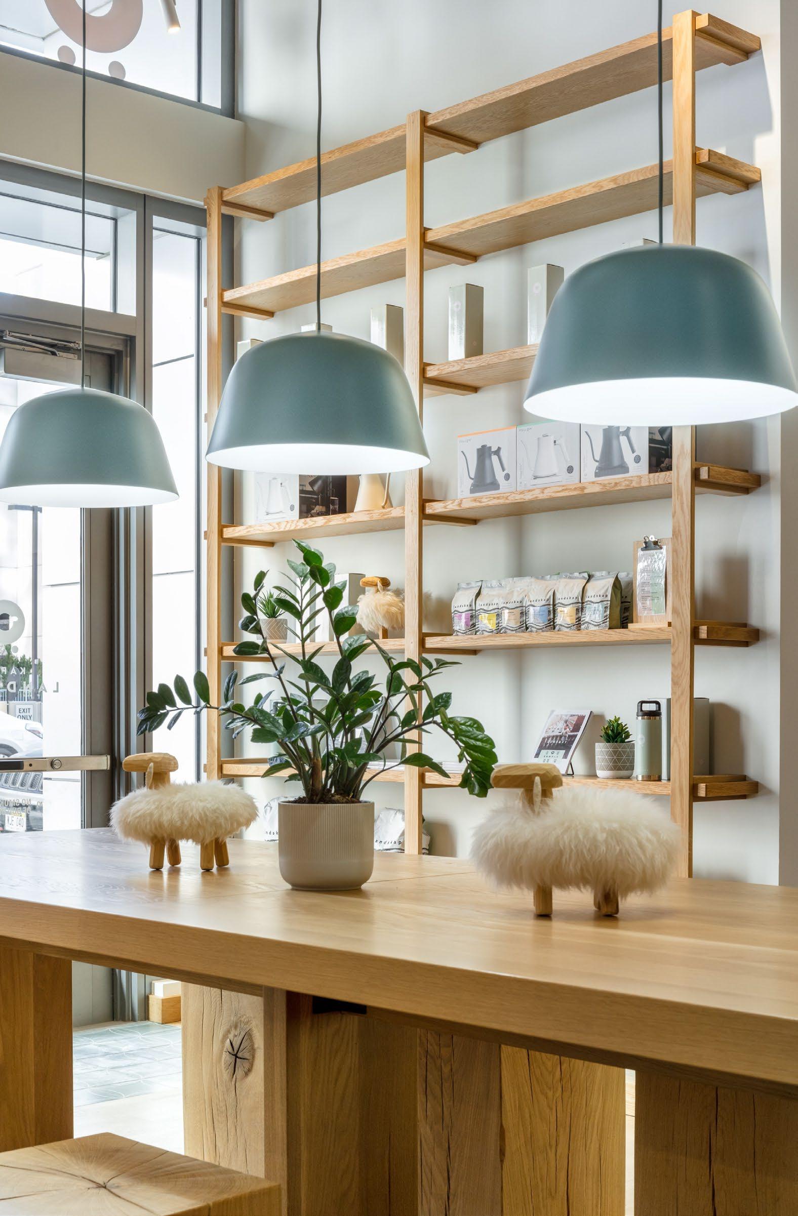
Millwork Window Bench & Oak Tables
Shelf
“Roth Sheppard Architects, made the core of what Landskap represents shine through. They found amazing wall/floor tile, they designed fantastically beautiful indoor/outdoor furniture, and they developed a bar layout that makes our baristas happy. We are grateful that we had them as partners for this project.”
-Thomas Tjarnberg, Owner, Kaffe Landskap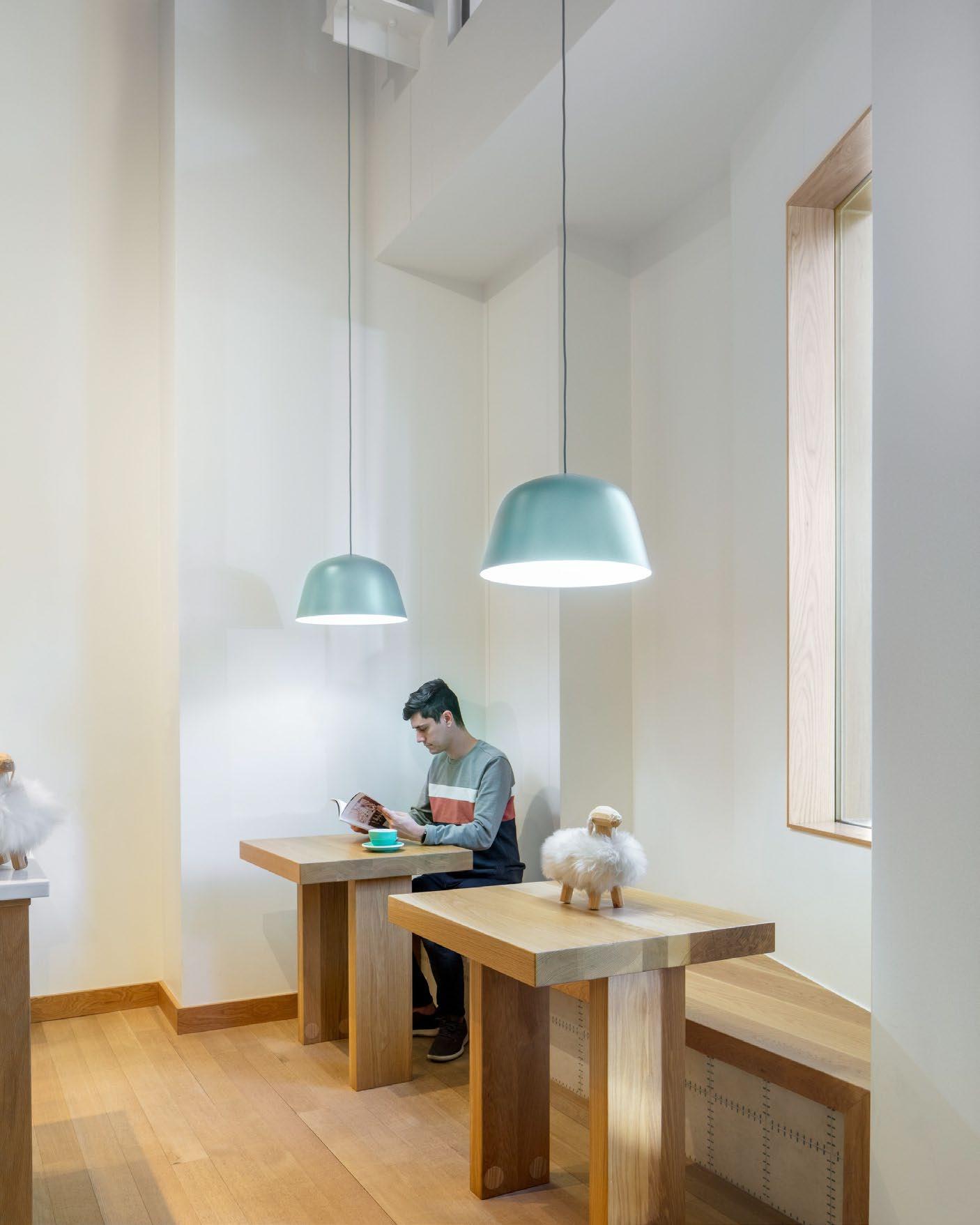
The Oak millwork was the prominent feature within the space. The grain pattern and wood tonality needed to be cohesive project-wide.
REJECTED!
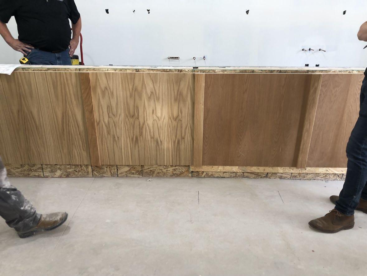
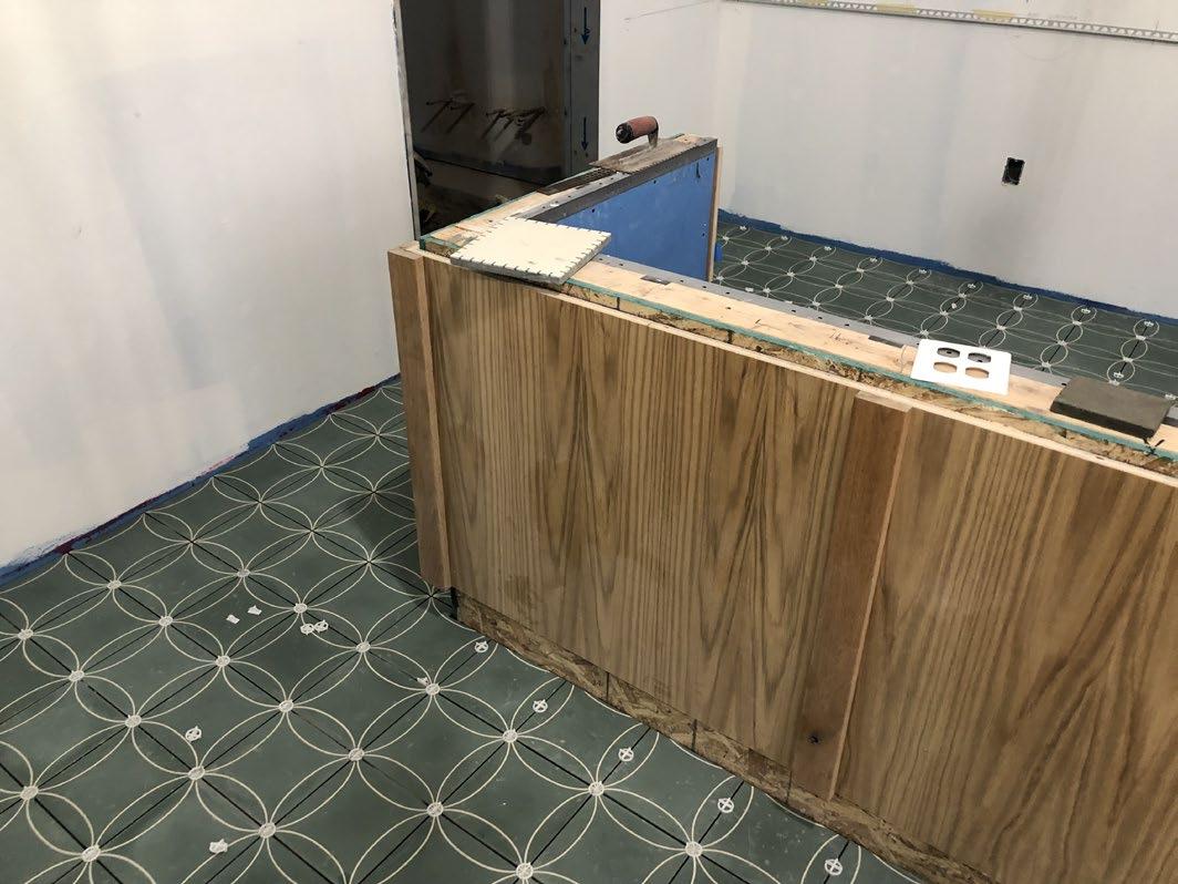
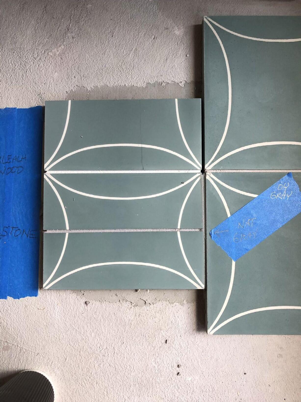
To ensure the concept was executed to the highest standard, I was meticulous about field testing all color choices: tile sealant, tile grout, millwork panels, and millwork finishes.
SECTION 1
Oak Coffee Bar
Punched Window With Steel Frame
Solid Oak Window Bench & Table
Suspended Solid Oak Shelf
Food & Beverage Storage / Prep
Swedish Tile Wall
The aperture pictured above was integrated into the shell building specifically for our Client. The custom detailed window trim and glazing splay warm light onto a private seating nook.
I played a key role in negotiating the overall design and details for openings within the Tenant shell walls, problem-solving the requirements of the Tenant Owner to also satisfy the concept of RSA's client, Kaffe Landskap.
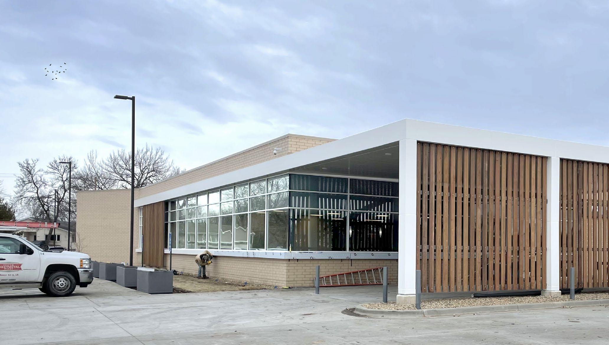
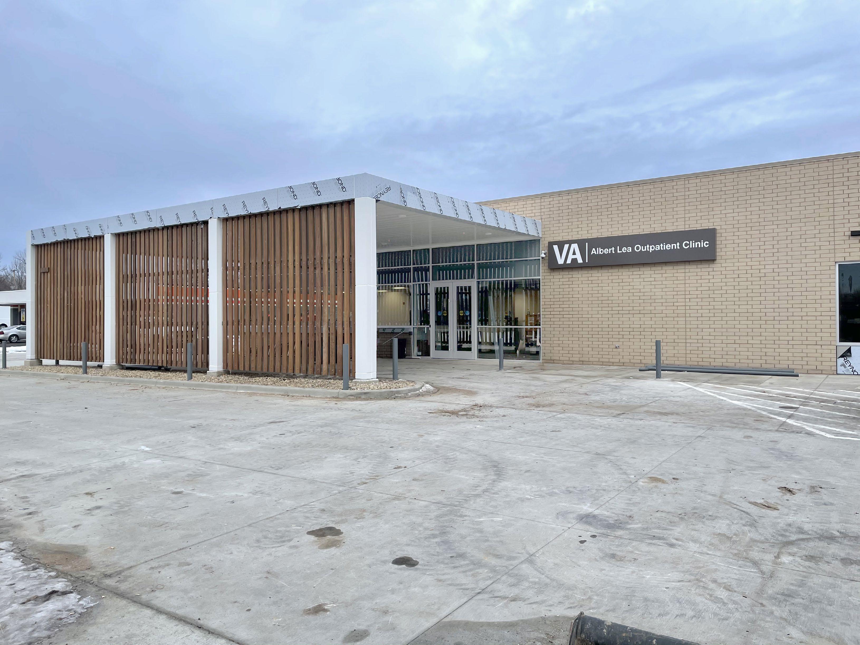
IVETERAN AFFAIR COMMUNITY CLINICS
ALBERT LEA | EVERETT | OWENSBORO
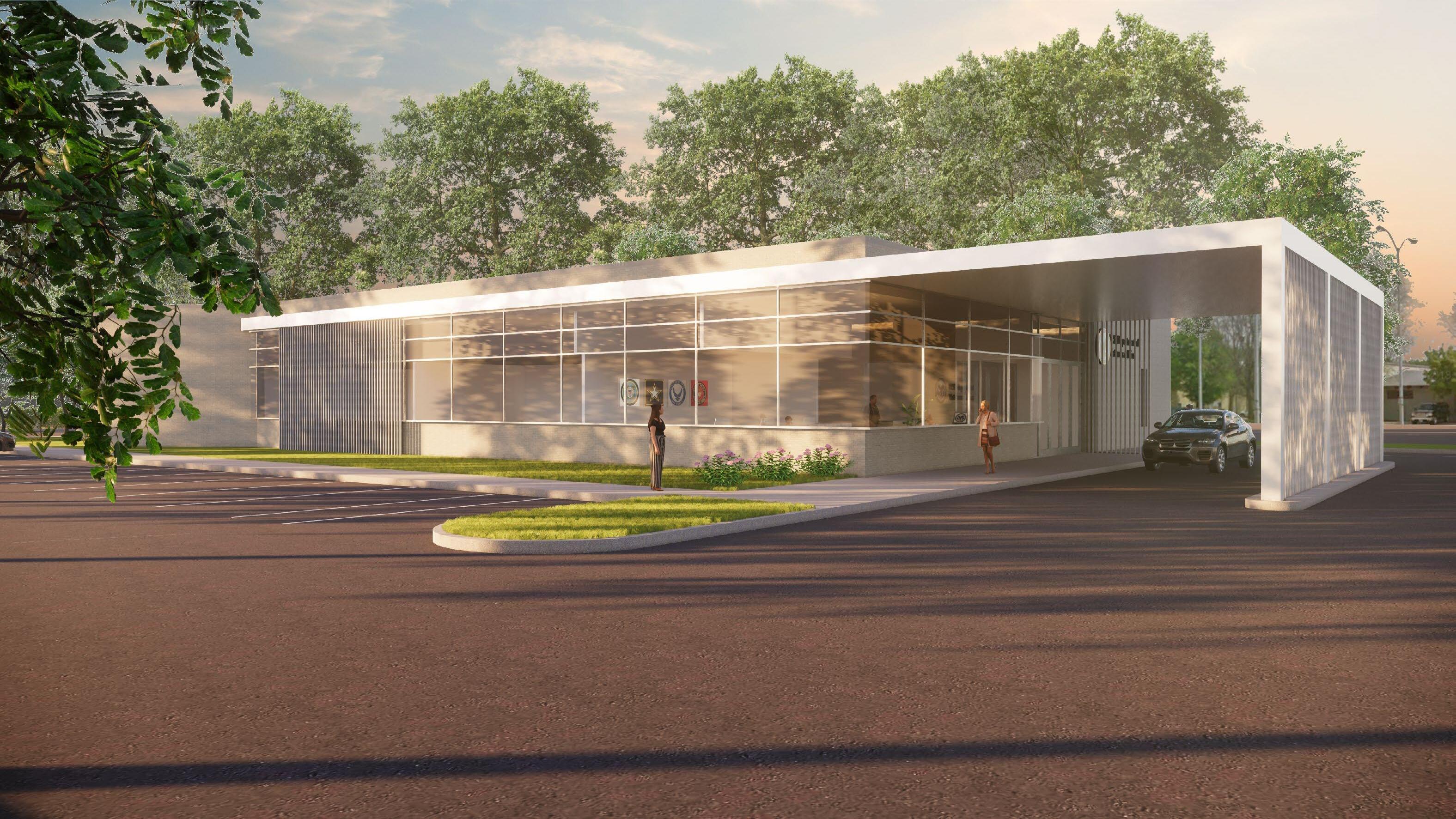
Proj. Type | VA Community Based Outpatient Clinics - New Construction
Location | Albert Lea, MN | Everett, WA | Owensboro, KY
Date | February 2020 - August 2023
Sustainability | 2 Green Globes
Lead Design | Natalie Siefiert, AIA, RSA
Professional Role | Arch II to Project Manager SD, DD, CD, CA
Firm | Roth Sheppard Architects
Project Brief
Over the course of 3.5 years, I participated in all phases of design for three ground-up Veteran Affair Community Outpatient clinics across the country. Each clinic was unique in its approach; through materiality, orientation, and opacity, the story of each community was told.
Individual Role
I served as the PA for all three clinics and took over as PM during the CA phase for each. My specific roles included:
• Documenting complete and coherent Document sets (SD-CD)
• Participation in Specification development
• Comprehensive code analysis and permit submission
• Coordinating with RSA’s client and the VA
• Traveling to the VA user groups for interviews and on-site design intent meetings
• Aiding in interior and exterior material selection
• Aiding in the design and layout of interior scope and exterior assemblies
• Coordination with sub-consultants
• Overseeing the entirety of Construction Administration
• Documenting project closeout
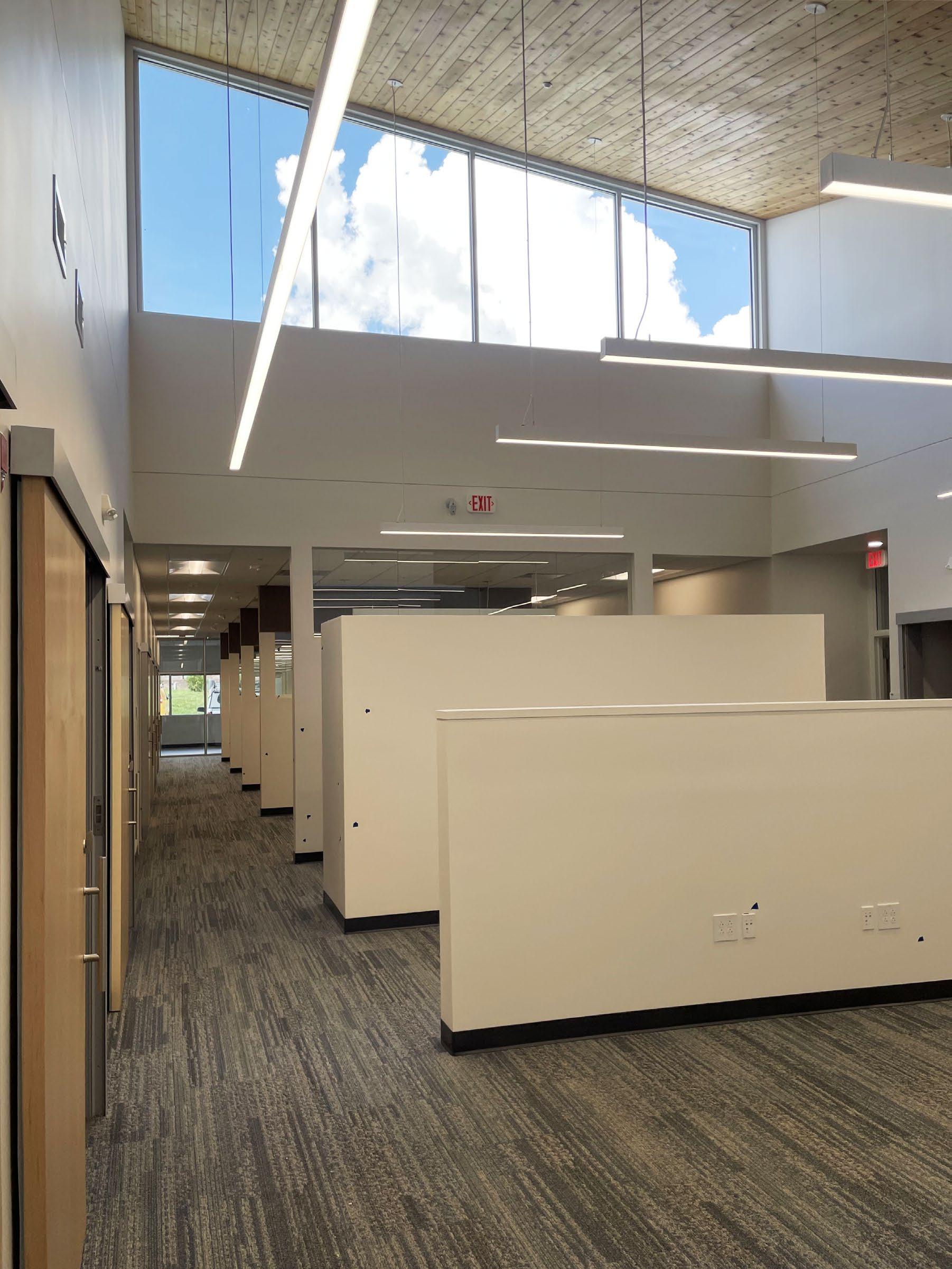
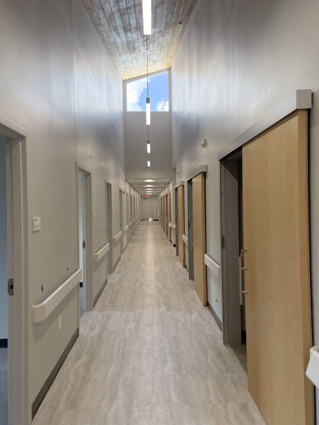
The internal layout of each clinic adheres to the PACT (Patient Oriented Care Team) diagram, facilitating efficient patient care while also establishing a clear separation between private and public functions. Following this approach, the VA care teams are centrally located within the core of the building, flanked by patient exam rooms.
.D3H&97'!&*1-"!$%&"711 -11&%)-97+5"&-+%&9)7''$+&.-'$)7-1&-DD$-)7+5&!$)$7+& -+%&.->&+('&/$&%2D17#-'$%0&2"$%&()&%7"#1("$%&97'!(2
/-#=$)&)(%&-+%&"$-1-+'0& /('!&"7%$"
51"3G *1-"!7+5&'(&#(+#$-1&')$-'$%& /1(#=7+50&/('!&"7%$"
"#!$%&2'717'>&/)7#=
44 $9-384<&51"3G&-'&D2+#!$%&(D$+7+5"
D
N@&9((%&"'2%&*)-.7+5& 9<&)34O&/-''&7+"21-'7(+
B<C@&D1>9((%&/-#=7+5 M-D()&D$).7-/1$&-7)&/-))7$)& :%-"!$%;
.D3H ?@&#(+'7+2(2"&)757%&7+"21-'7(+
/-#=$)&)(%&-+%&"$-1-+'0& /('!&"7%$"
B<C@&5>D&/(-)% *1-"!7+5&'(&#(+#$-1&')$-'$%& /1(#=7+50&/('!&"7%$"
-BAN?
"#-1$F &4&4<?@&R&4I38@
O '>D&$KD-+"7(+&,(7+'
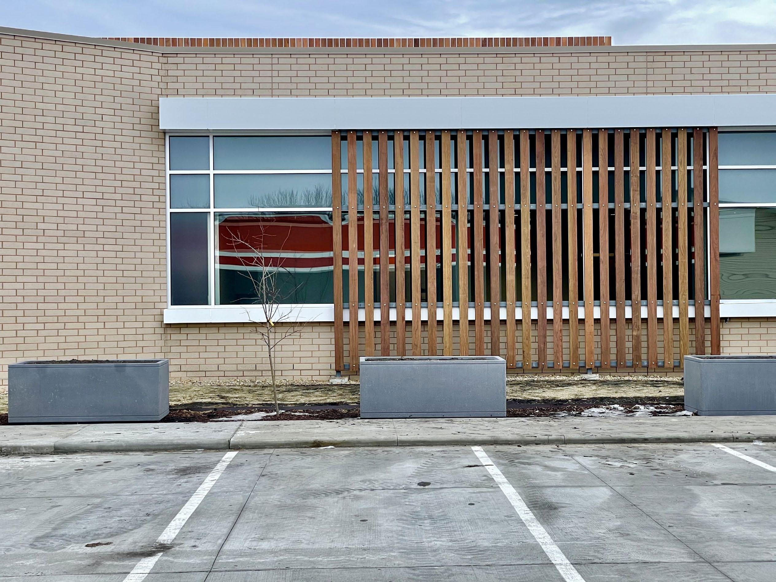
Specially designed bricks were designed and coordinated with the mason to achieve a seamless masonry layout around the entire perimeter of the building.
"#-1$F &4&4<?@&R&4I38@
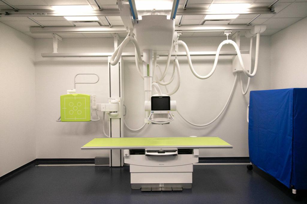
A high level of coordination between consultants, the user group (VA), the GC, and the subcontractors was required for the placement of imaging hardware throughout the clinic.
#2"'(.&.(1%$%&2'717'>&/)7#= #(+#-M$&.()'-)&,(7+'"0&'>D
"#!$%&2'717'>&/)7#=
?&4<C@&-7)&#-M7'> ?@&)757%&7+"21-'7(+ M-D()&D$).7-/1$&-7)& /-))7$)&:%-"!$%; B<C@&D1>9((%&"!$-'!7+5
-175+ ## !
B < C ' >
"#!$%&2'717'>&/)7#=
C #(2)"7+5&-'&+()'!&-+51$%&#()+$)
4 8@ H@
!&###%
B<C@&5>D"2.&9-11&/(-)%
N@&9((%&"'2%&*)-.7+5&9<&& /-''&7+"21-'7(+
B<C@&D1>9((%&"!$-'!7+5
M-D()&D$).7-/1$&-7)& /-))7$)&:%-"!$%;
?&4<C@&-7)&#-M7'> ?@&)757%&7+"21-'7(+
"#!$%&2'717'>&/)7#= #2"'(.&.(1%$%&2'717'>&/)7#= #(+#-M$&.()'-)&,(7+'"0&'>D
#(2)"$&-/(M$&<&/$1(9 #2"'(.&.(1%$%&2'717'>&/)7#=& -H //
P $9-384&)$'2)+&-'&9$"'&$+')>
"#-1$F &4&4<?@&R&4I38@ -BAN?
'::)..%&'()".%.0'""%1)%/)$6!6)+%6(%-0)%!6)"+% 36-0%-0)%'$:06-):-%&$6#$%-#%$#8*0 6(< 8(")..%#-0)$36.)%+6,)(.6#()+;%"#:'-)% +##$%#&)(6(*.%DE%!$#,%-0)%'+F':)(-%
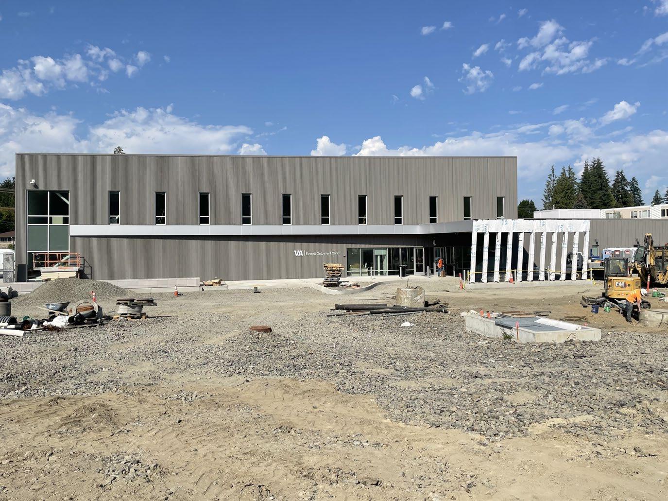
VA Everett serves a larger community and patient group compared to the Albert Lea and Owensboro clinics. To accommodate this, the PACT method was modified to achieve an efficient layout for Patients and care teams. The modification involves four individual PACT 'Pods,' allowing specialized teams to focus on their group of patients. Patient-oriented group functions and lab services are strategically placed along the perimeter of the building to facilitate easy navigation for patients.
The building's opaque nature emphasizes patient privacy. Dark, reflective glazing and a steel curtain not only provide a disguise for patients but also reflect the VA's commitment to privacy.
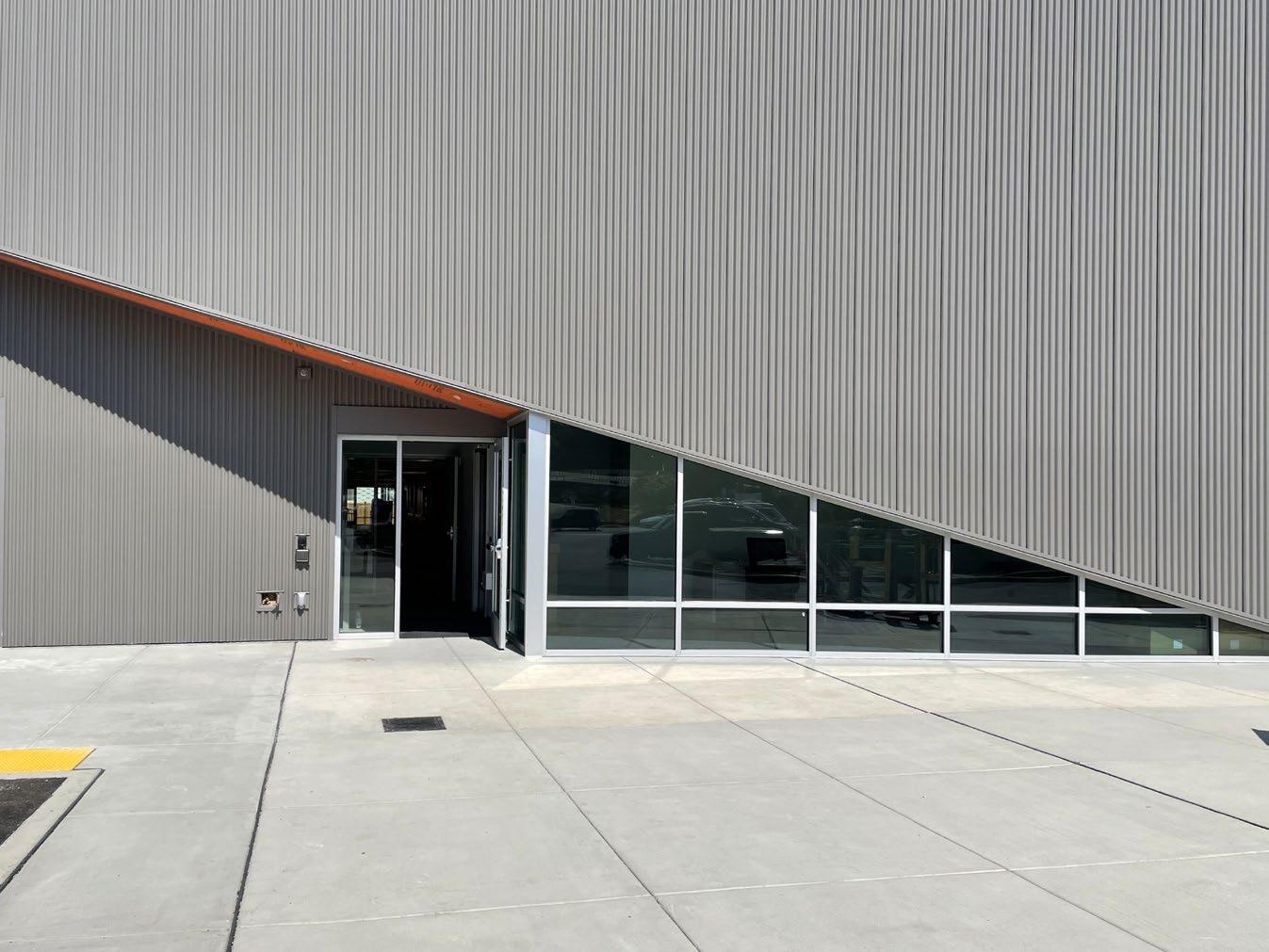
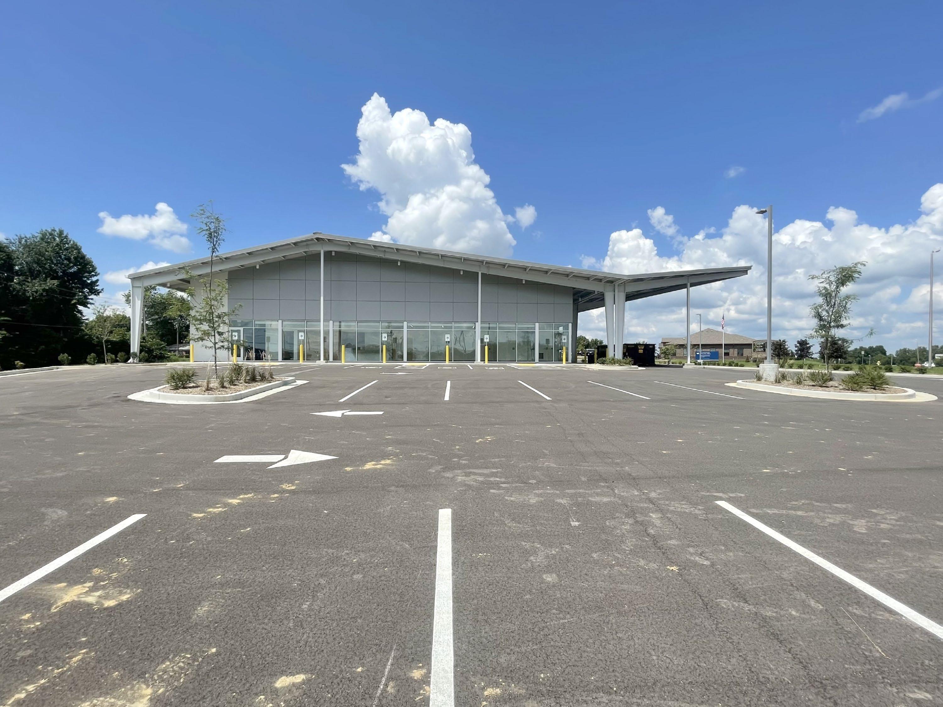
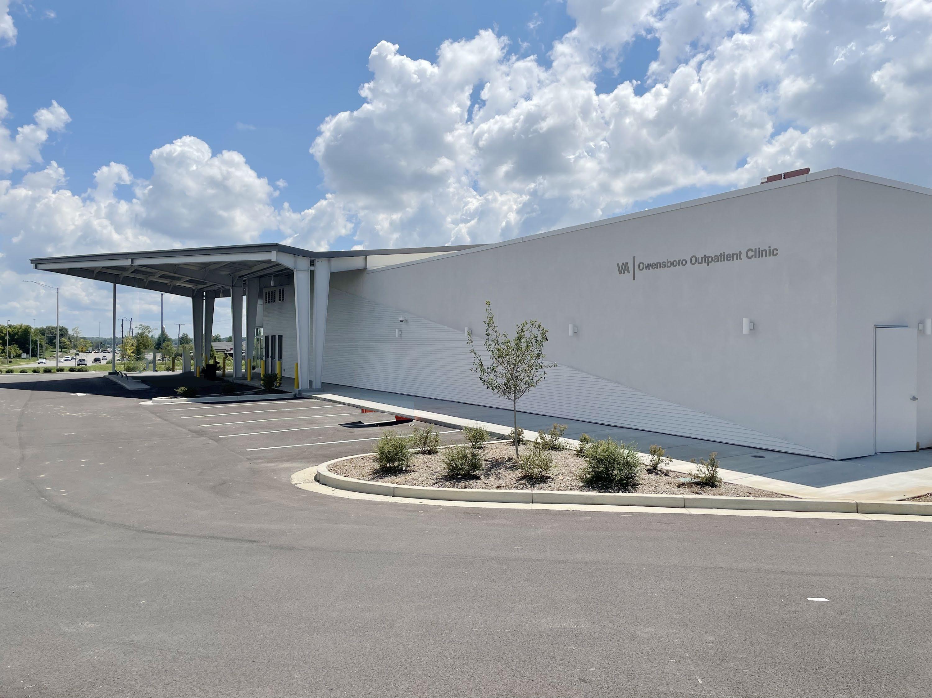
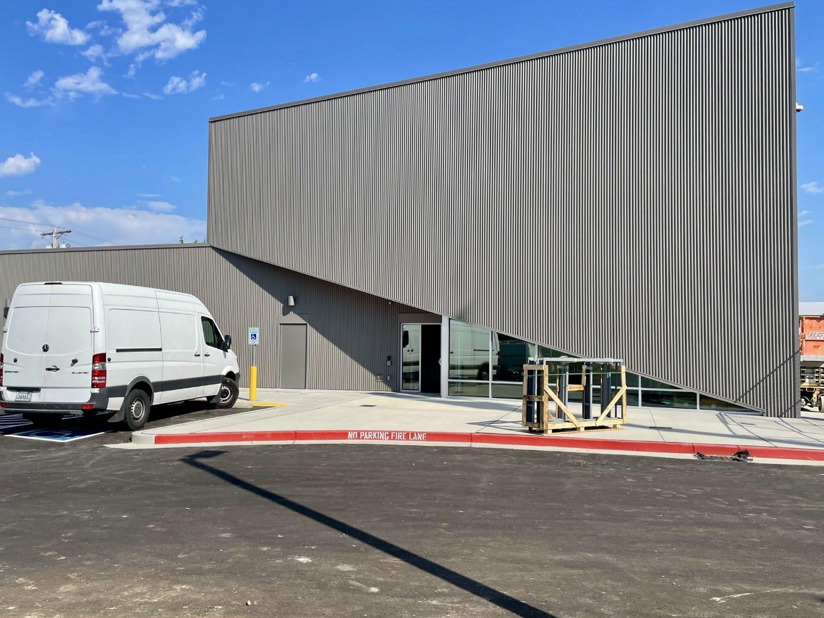
VA Owensboro serves a small Kentucky community located two hours away from the nearest major city. The Client necessitated an efficient and timely construction approach for this project, relying on regional contractors and materials. Two construction schemes were employed: prefabricated steel elements facilitated the efficient construction of the canopy, while a traditional wood-framed structure was seamlessly integrated below, enabling a swift build-out of the main clinic interiors.
At the intersection of the prefabricated steel element and the main structure, a skylight connects the volumes, offering ample natural light for staff and serving as a guiding element for visiting patients.
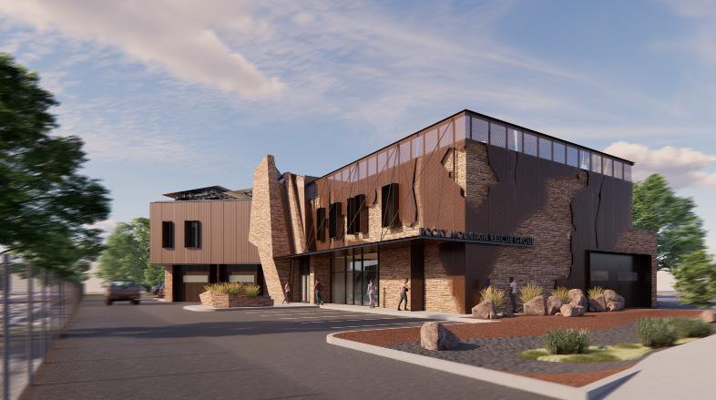
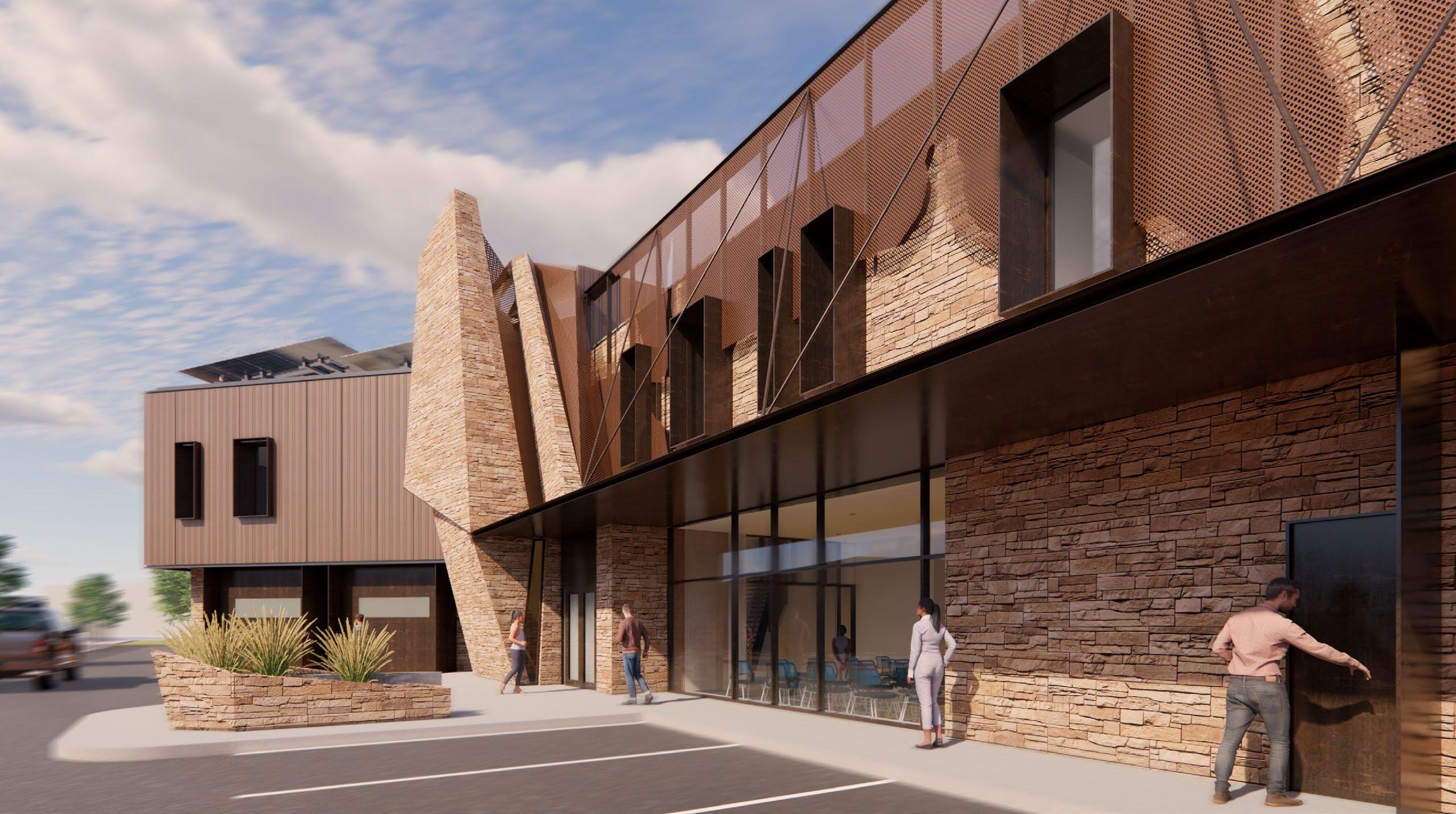
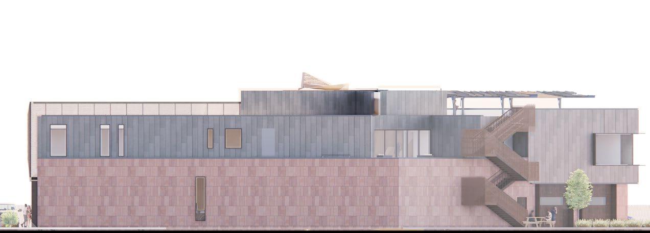
IROCKY MOUNTAIN RESCUE GROUP
Proj. Type | Rocky Mountain Search and Rescue Headquarters // 16,800 SF
Location | Boulder, CO
Date | April 2022 - January 2023
Sustainability | Net Zero
Lead Design | Ryan Helle, Adam Harding, Principal RSA
Professional Role | Project Manager, Lead Design
Project Phase | Schematic Design, Programing, Cost Estimation
Firm | Roth Sheppard Architects, Partnered with TCA Architects
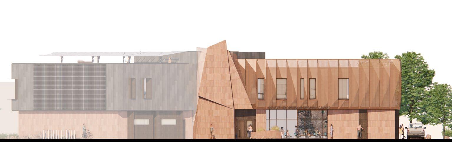
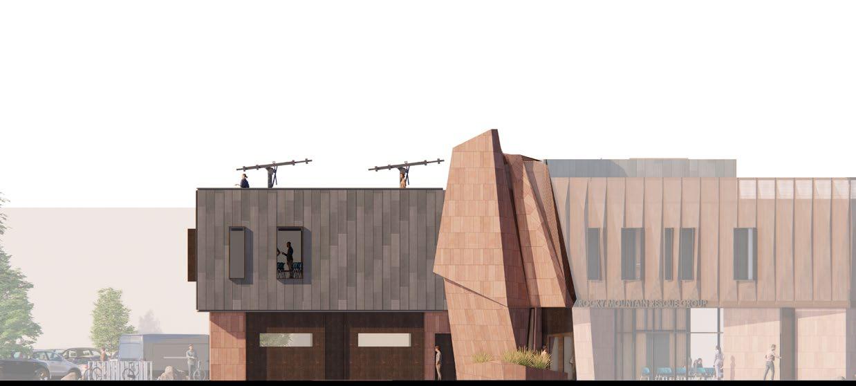
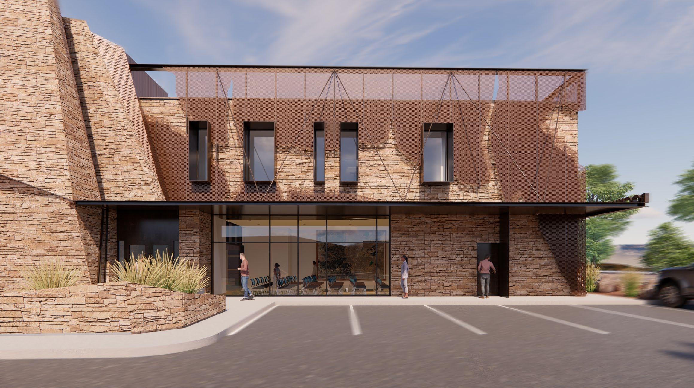
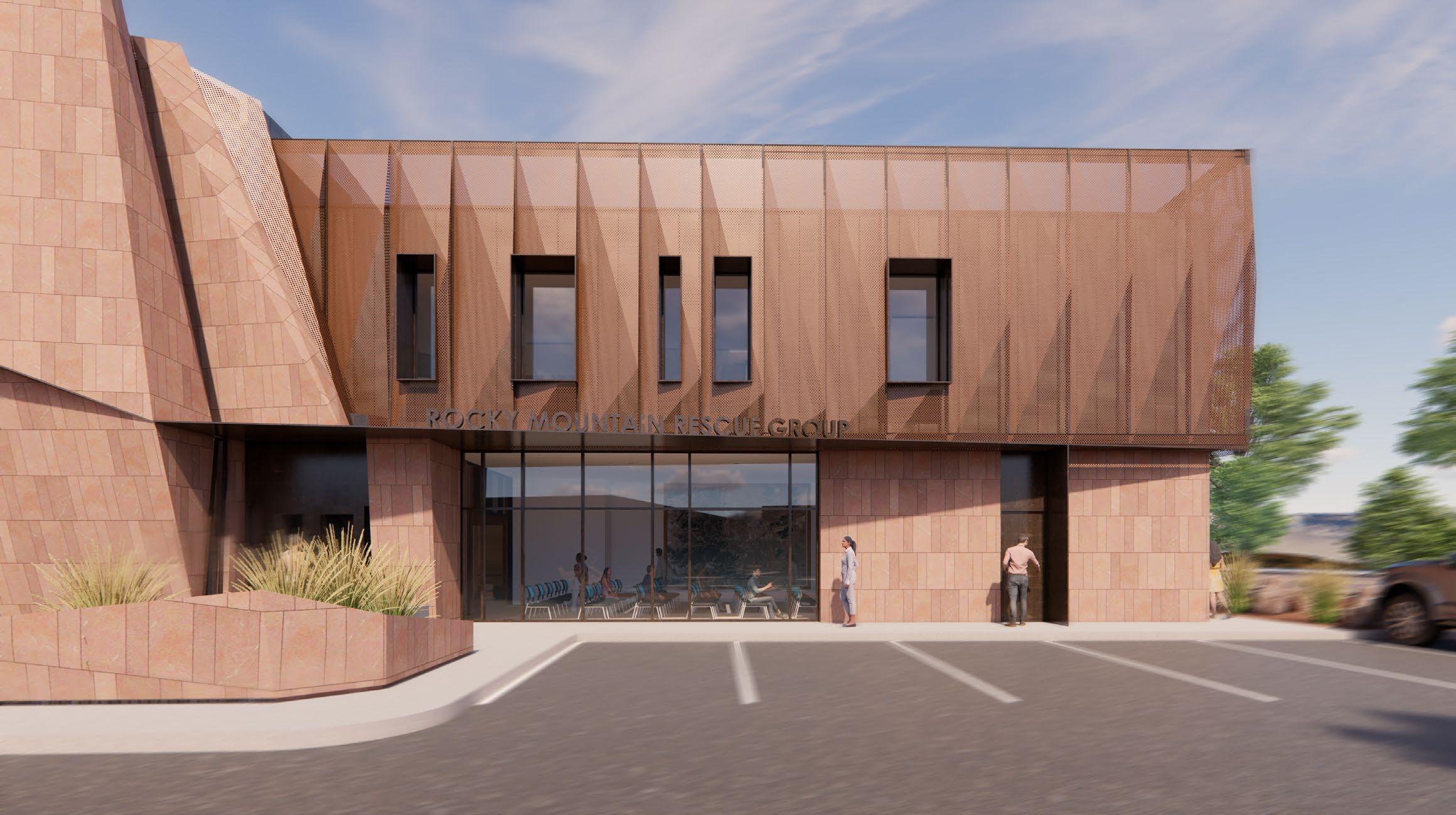
APPROACH FROM WALNUT ST - RESCUE MISSION SCREEN
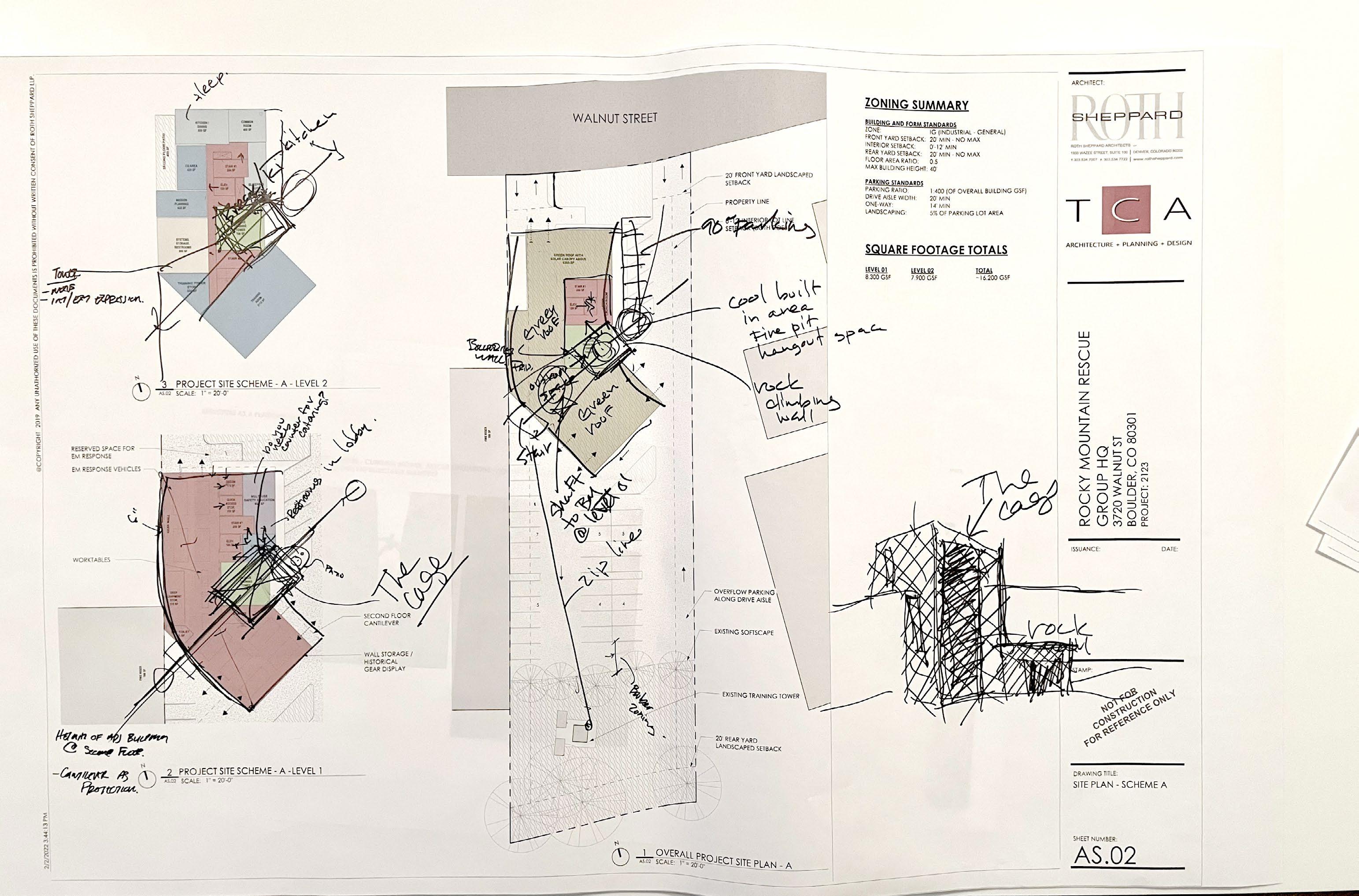
Rocky Mountain Rescue Group, dedicated to search and rescue operations in the Rocky Mountain region, engaged RSA ,in partnership with TCA, for a study on their new Headquarters. This collaborative team conducted a thorough analysis, including site assessment, programming, and cost evaluation of their existing property, ensuring the 17,000 sq. ft. building meets all future requirements. Simultaneously, RSA spearheaded the schematic design for the innovative net-zero
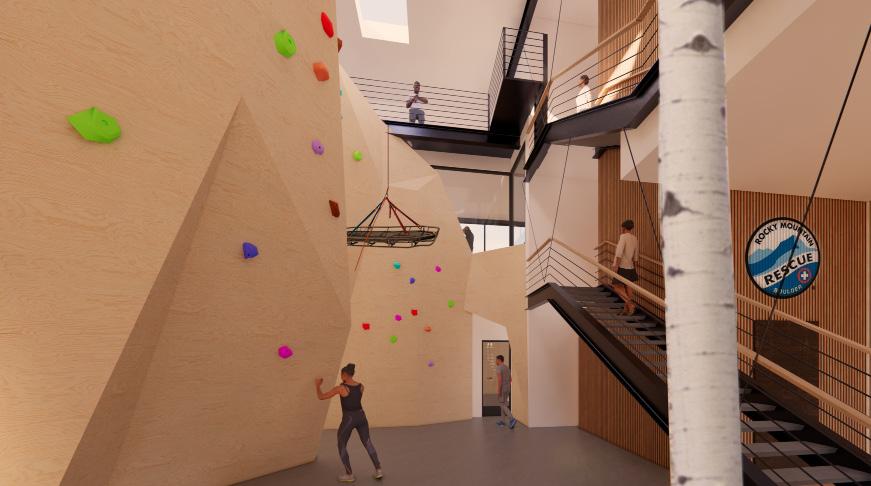
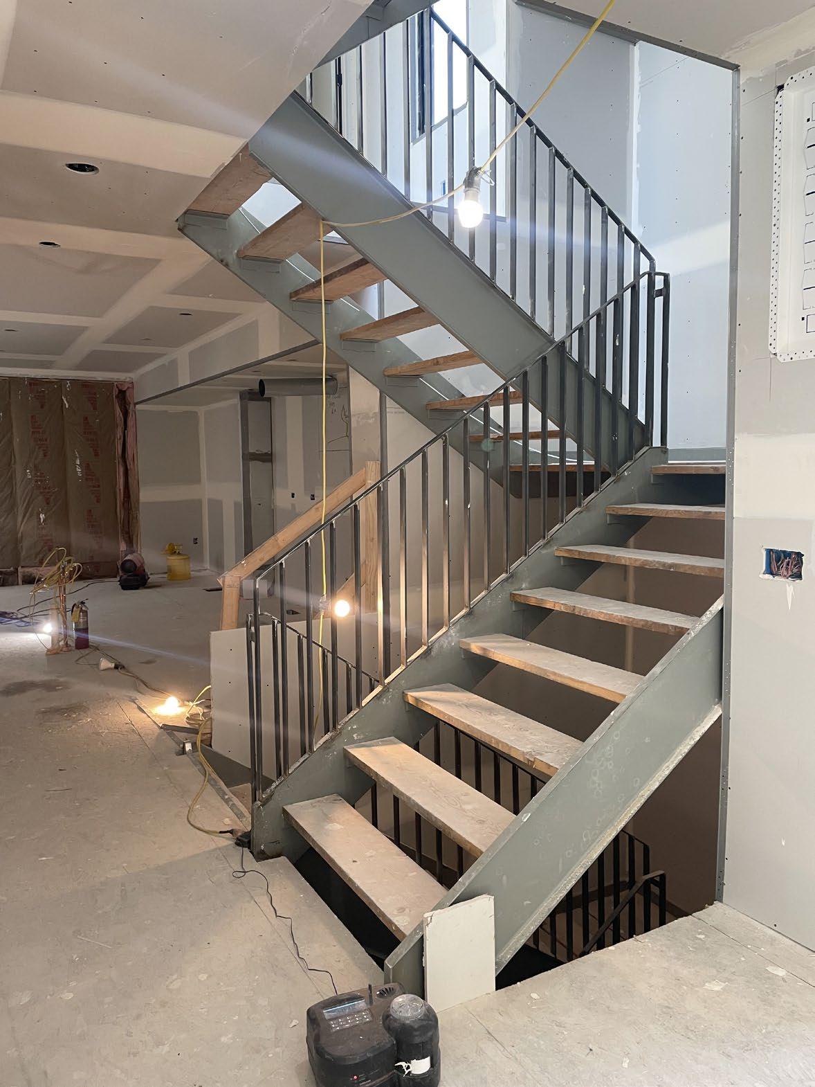
The "Cage," a training tower with historical significance for RMRG, acts as the central hub of the building, connecting ground-level rescue and training facilities with public spaces and second-level residences with private RMRG functions. The building's flexible structure accommodates various unforeseen uses, providing RMRG with a versatile training tool. A solar canopy array on the roof and a vertical
• Leading group wide discussions, design charettes, and project
• Leading project design
• Producing SD presentation renderings
• Documenting project closeout
To the right: The internal training tower, known as the "Cage," functions as the central hub for the entire building. It unites all floors and functions, offering crucial visual and activity cues that facilitate efficient communication, a necessity for rescue operations. Additionally, the tower can be opened for public presentations to showcase the Group's work.
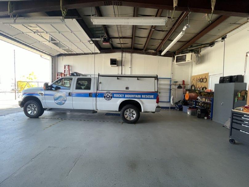
!"#$%!&%'($%)($*#!+$','-&../'0'#%1!"!"2'#&3$%'
!"#$%!&%'($%)($*#!+$','-&%.)#/#!&")0'12!*.')#&%/3$','4&&.!"3'!"#&'/(('5/6
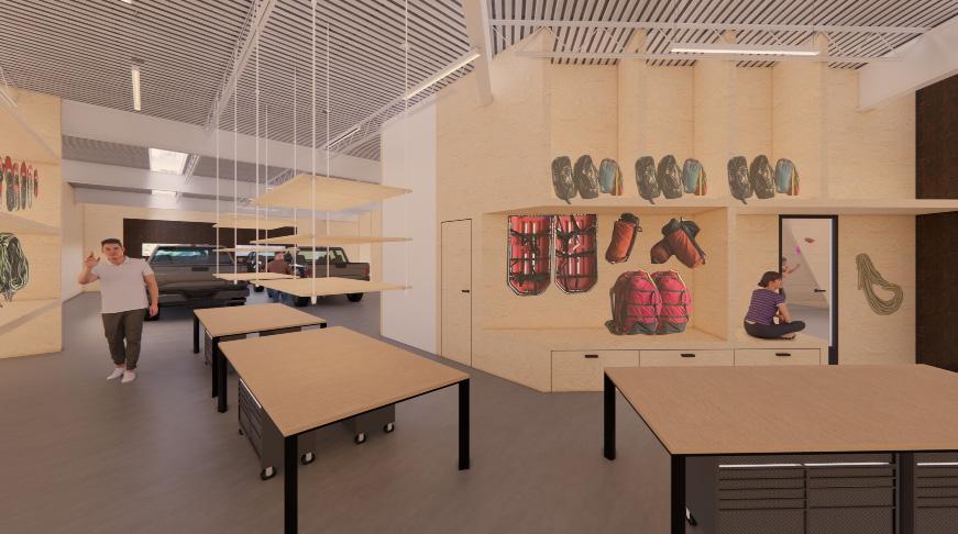
Above: RMRG takes pride in crafting unique tools that cater to their needs during rescue operations. Internal workspaces were incorporated to encourage collaborative work and facilitate swift communication between the two vehicle rescue bays.
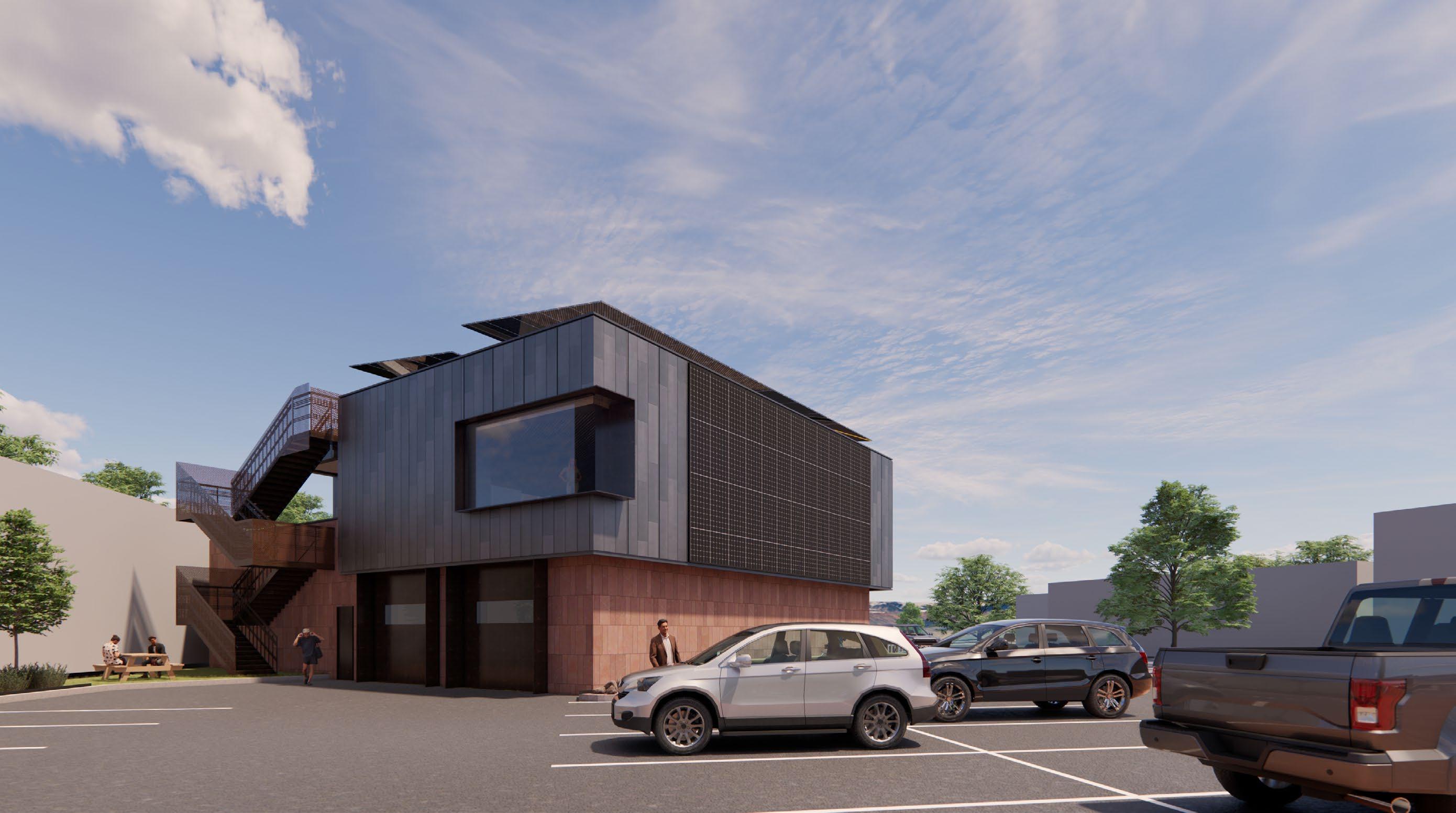
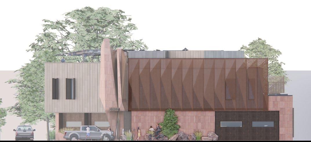
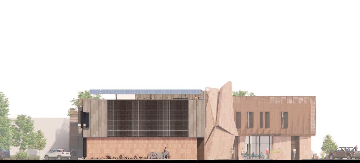
To the right: A south facing solar wall was designed to capture sufficient solar energy to provide 40% of the facility's energy requirements.
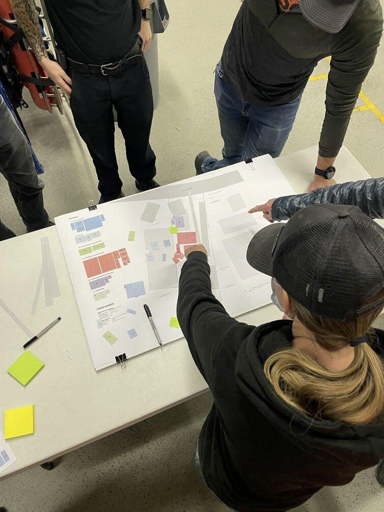
RSA conducted several site visits and meetings with RMRG to grasp the distinctive aspects of their work.
Securing buy-in from the entire RMRG committee was crucial to guarantee that the project would effectively meet their future requirements.
The image on the left is from a public charrette that I facilitated, providing smaller RMRG teams with an opportunity to offer feedback and showcase critical program connections. These smaller charrettes created a platform for everyone's voice to be heard.
 !"#$%&'"()*+,)&!-.#(-&/!"(0 ""!#$%&!"'"" !"#$%&'(")*$!(+,)-.$!$,'&'(/,)0)12
(+!$&()(*+$,"-&.&)+$(&+/$(0-""-
!"#$%&'!$('!)#*+!&,&-../*"0&1!(#
(+!$&()(*+$,"-&.&)+$(&+/$(0-""-
!"#$%&(+!$&()(*+$,"-&.&)+$(&+/$(0-""-
!"#$%&(+!$&()(*+$,"-&.&)+$(&+/$(0-""-
!"#$%&'(!$&()(*+$,"-&.&)+$(&+/$(0-""-
!"" #$%&'($)*")+,-."'&/".$-/.%,-&0"%1(-".%,-&"2&-&&'" 3(-(.1*".$-/4)$.%&/0".#,,%1"3$5& 6" #$%&'($)*"#,/7)$'"8&'3,'$%&/".%&&)"'$(-.5'&&3(-(.1*"'7.%&/".%&&)
9 #$%&'($)*".%,'&3',-%"#7))(,-.":"(-.7)$%&/";)$<(-; 3(-(.1*".%,'&3',-%0"4)$5="$-,/(<&/>";)$<(-;0"
!"#$%&'"()*+,)&!-.#(-&/!"(0 ""!#$%&!"'"" !"#$%&'(")*$!(+,)-.$!$,'&'(/,)0)1
-"0$%&()(*+$,"-&.&)+$(&+/$(0-""-
-"0$%&()(*+$,"-&.&)+$(&+/$(0-""-
!"#$%&()(*+$,"-&.&)+$(&+/$(0-""-
!"#$%&()(*+$,"-&.&)+$(&+/$(0-""-
'(!$&()(*+$,"-&.&)+$(&+/$(0-""-
? #$%&'($)*"'&5+5)&/"<(-5@$)7#(-7#".%$-/(-;".&$#"'$(-.5'&&-" 3(-(.1*"-$%7'$)
Lyons Red Sandstone, thin stone veneer
Finish: Sandblasted, Smooth Face
A #$%&'($)*".%'75%7'&0".%&&)>".%$('0".,)(/"#&%$)"5)$//(-; 3(-(.1*"'7.%&/
Modular Perforated Steel Rainscreen
Finish: Raw Steel, rusted
Storefront Mullions + Insulated Glazing
Finish: Black Anodized
!"#$%&'(!$&()(*+$,"-&.&)+$(&+/$(0-""-
1 2 3 4 5
Recycled Zinc-Aluminum Standing Seam Rainscreen
Finish: Natural
Steel Fascia
Finish: Raw Steel, rusted
!"" #$%&'($)*")+,-."'&/".$-/.%,-&0"%1(-".%,-&"2&-&&'" 3(-(.1*".$-/4)$.%&/0".#,,%1"3$5& 6" #$%&'($)*"#,/7)$'"8&'3,'$%&/".%&&)"'$(-.5'&&3(-(.1*"'7.%&/".%&&) 9 #$%&'($)*".%,'&3',-%"#7))(,-.":"(-.7)$%&/";)$<(-; 3(-(.1*".%,'&3',-%0"4)$5="$-,/(<&/>";)$<(-;0" ? #$%&'($)*"'&5+5)&/"<(-5@$)7#(-7#".%$-/(-;".&$#"'$(-.5'&&-" 3(-(.1*"-$%7'$) A #$%&'($)*".%'75%7'&0".%&&)>".%$('0".,)(/"#&%$)"5)$//(-; 3(-(.1*"'7.%&/
'(!$&()(*+$,"-&.&)+$(&+/$(0-""-
Exterior design options presented to the Client.
The choices in materiality reflect the robust nature of the group and the landscape in which they operate.
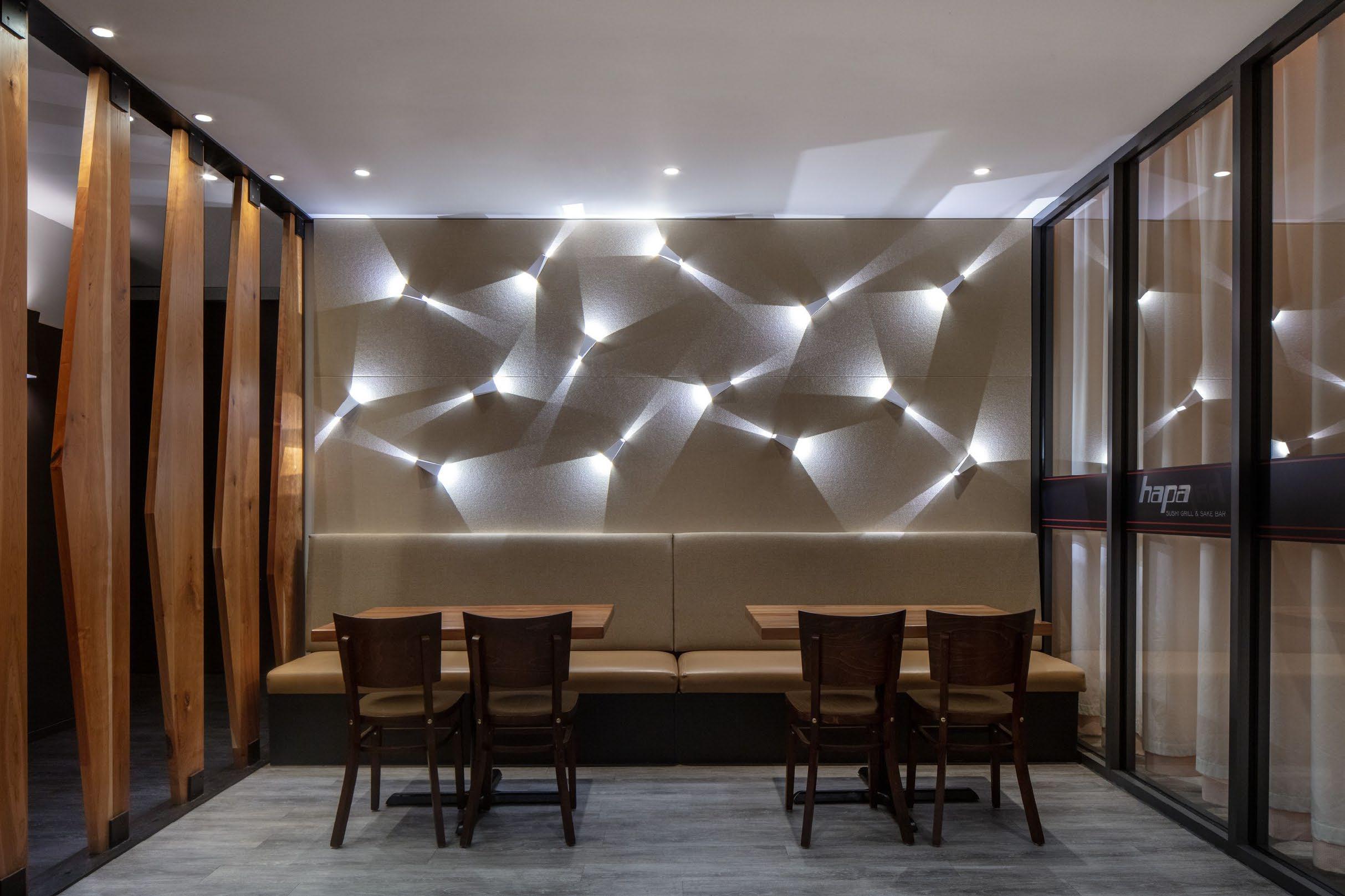
My tenure at RSA allowed me to contribute to a diverse range of projects. In addition to the professional projects showcased in this portfolio, these included, but were not limited to, a residential project in the Highlands, multiple Hapa Sushi restaurants, and a highly technical Federal project (subject to a non-disclosure agreement).
Throughout each assignment, I endeavored to uphold the design excellence and unwavering commitment to client satisfaction that characterized RSA's body of work. The experience provided me with substantial exposure to all phases of a project. I highly value this experience, as it reinforced my dedication to achieving excellence in design through documentation and within the field.
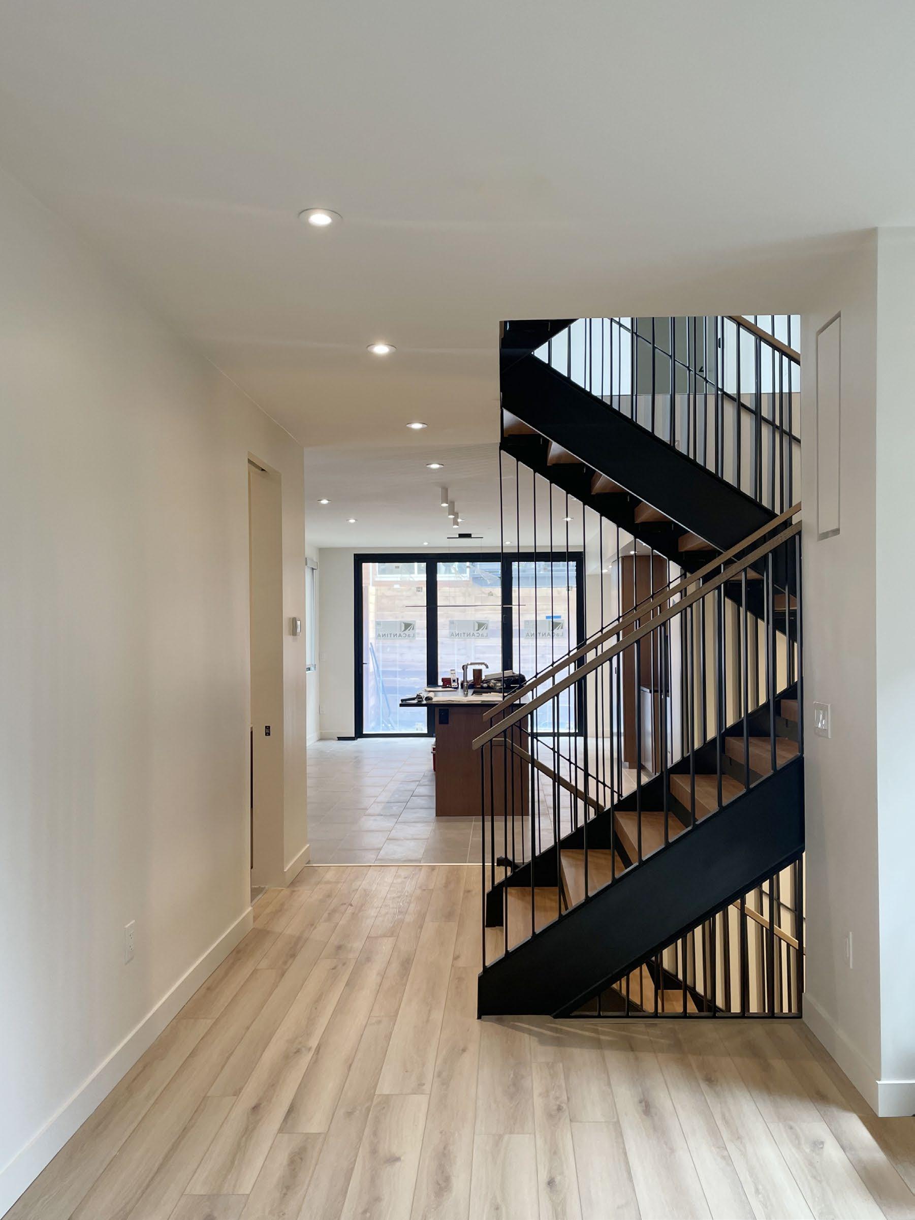
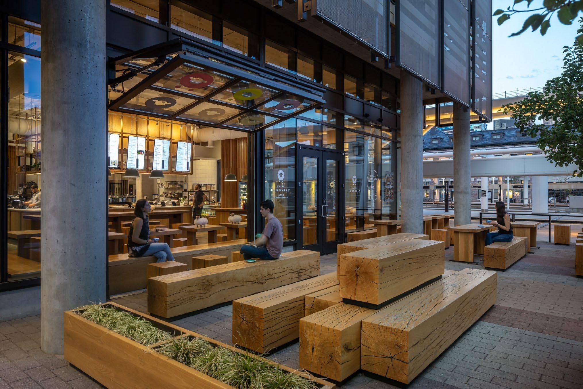
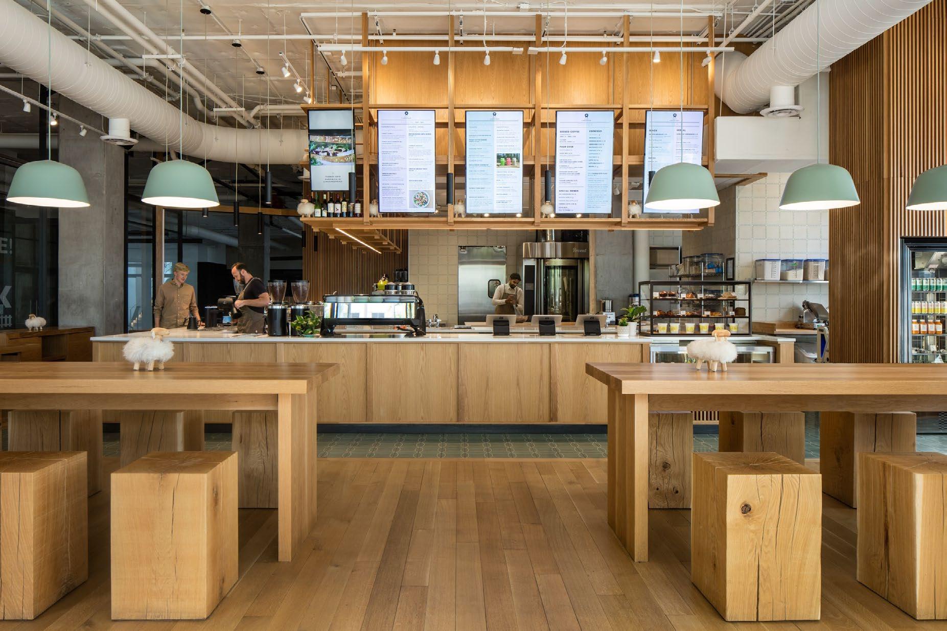
Situated at the core of Union Station, Kaffe Landskap's flagship location serves as a lively social hub within Denver's bustling district. Although my primary focus was on the 1401 project, I actively contributed to the coordination of design details and played a significant role throughout the entire construction administration phase.

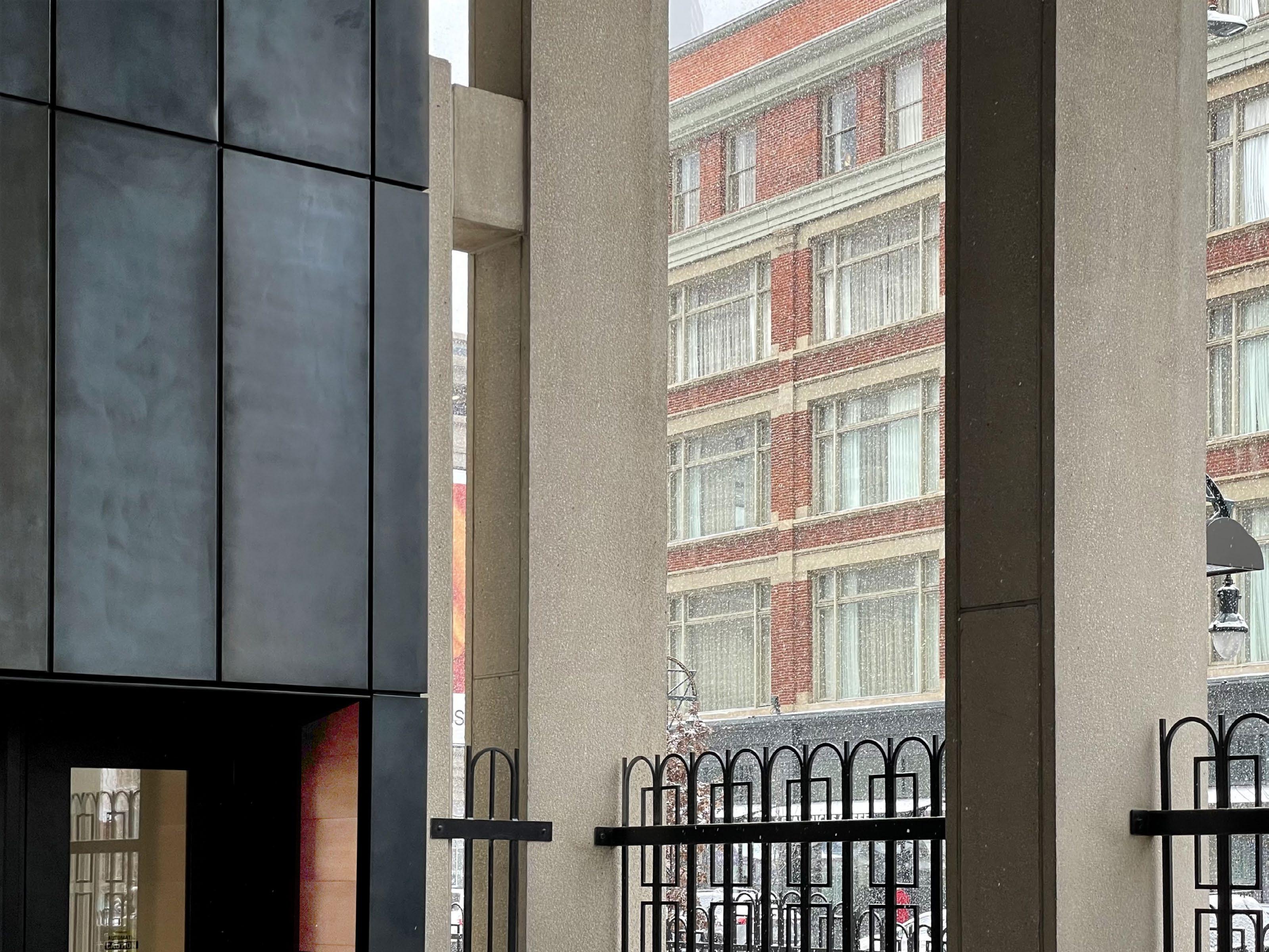
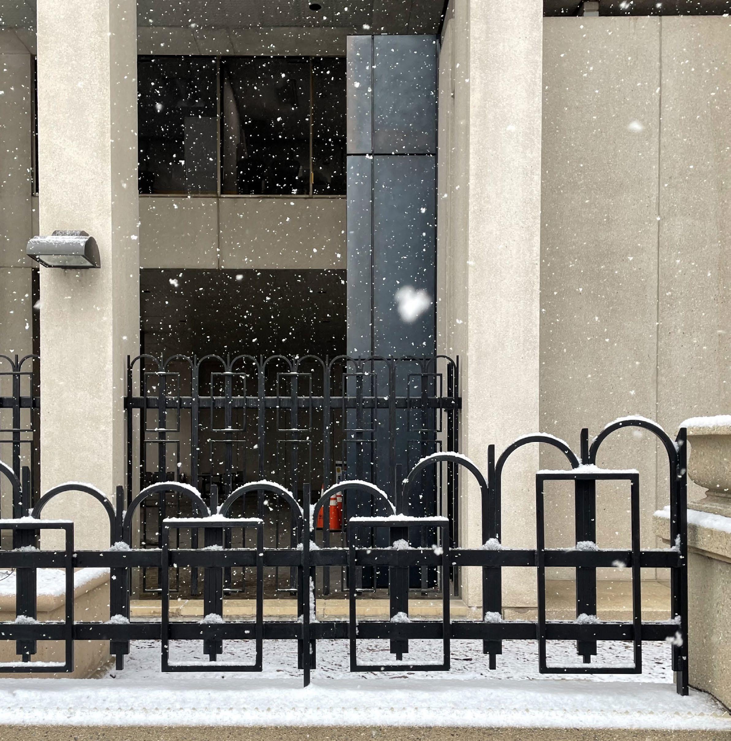
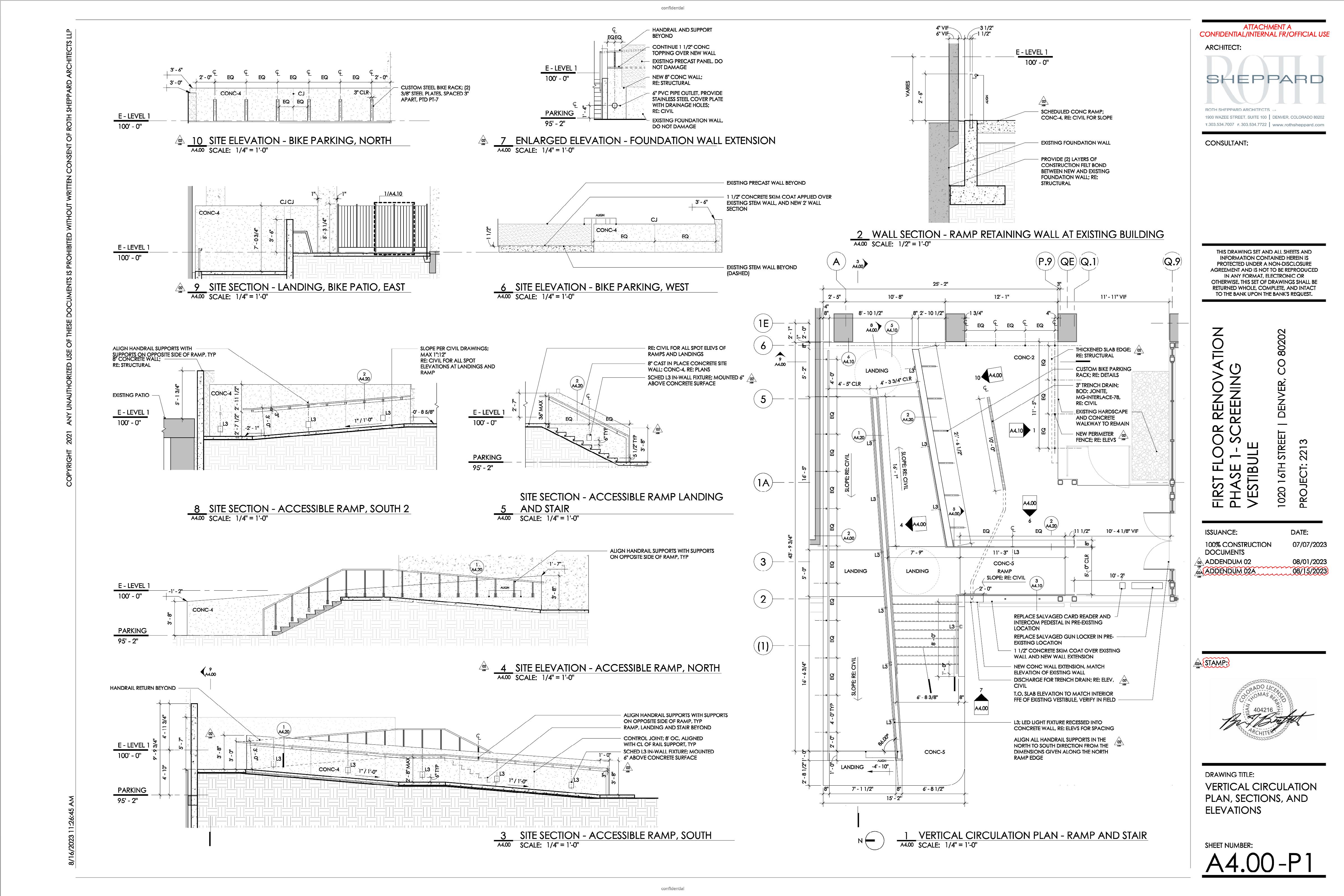
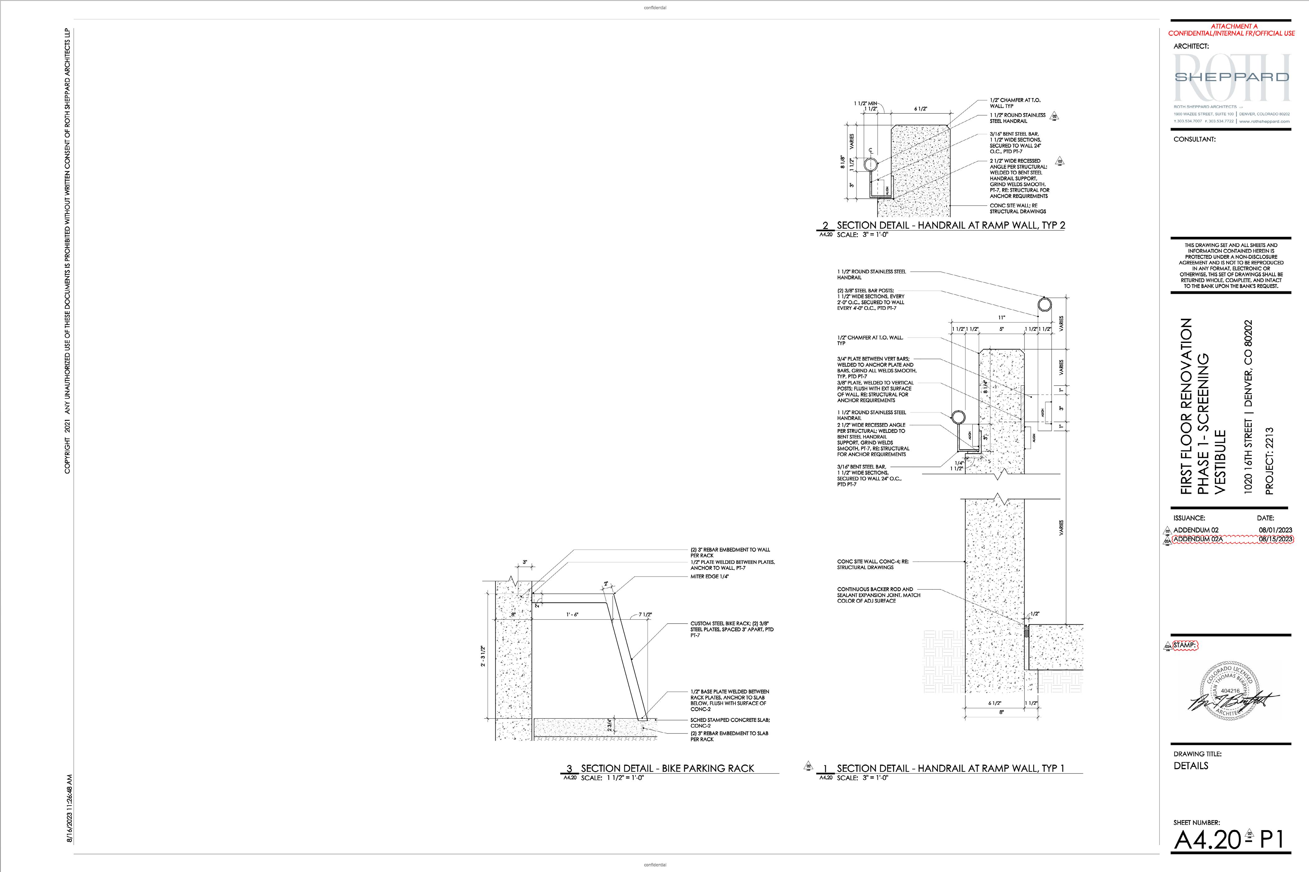
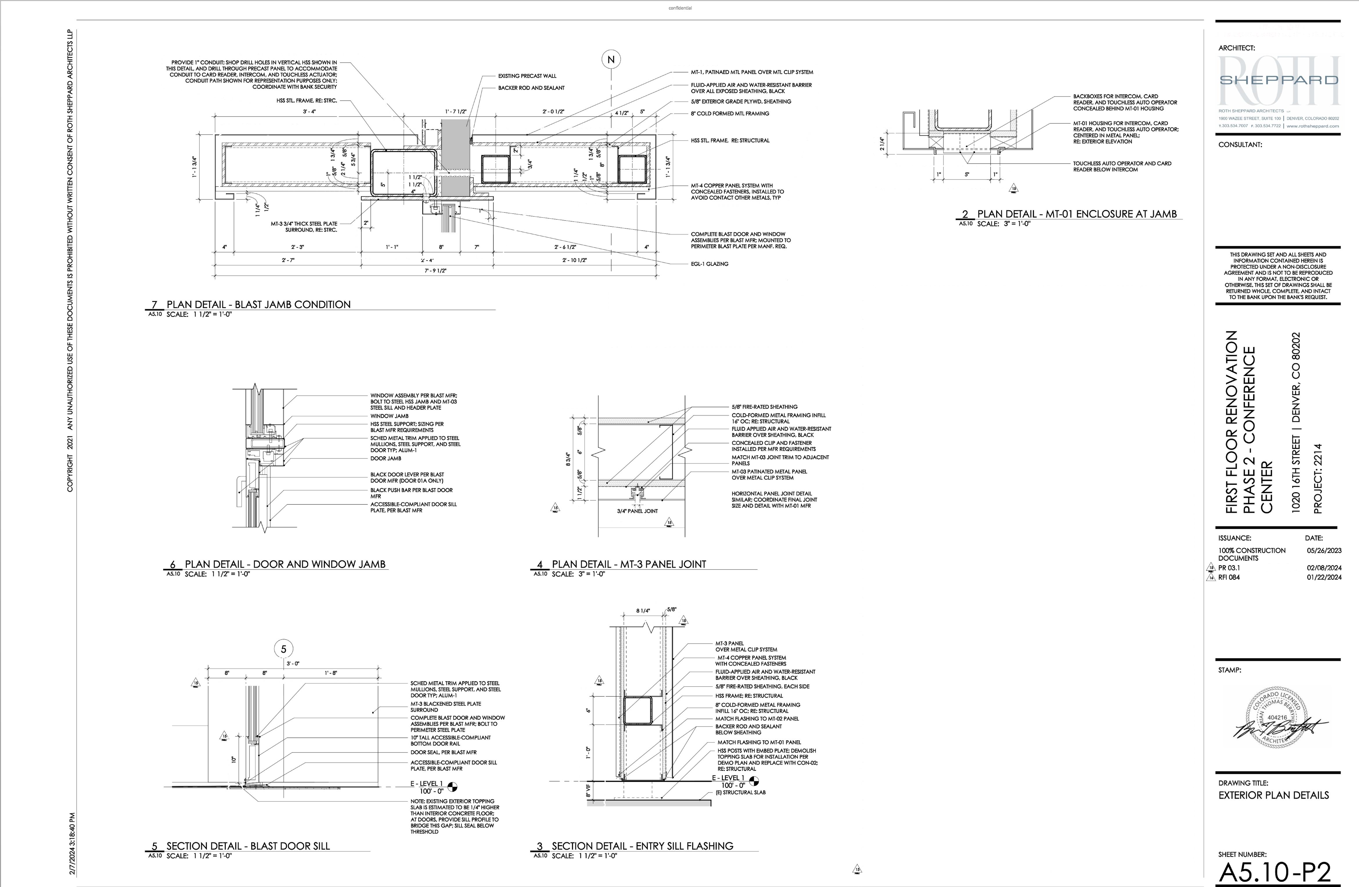
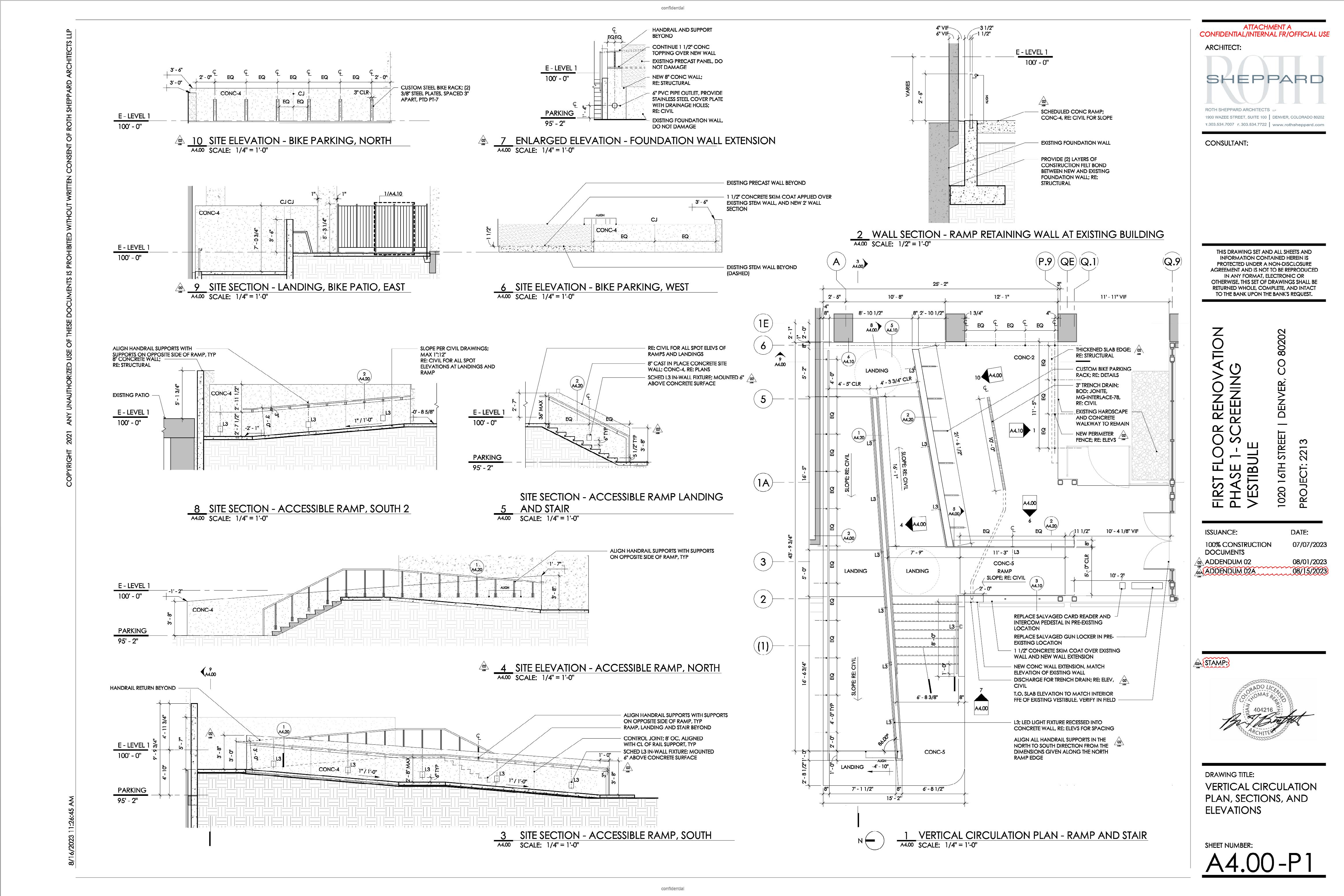
The technical drawings and details provided here are extracted from various projects I worked on during my time at RSA, all of which I was responsible for drafting. If you require a more comprehensive set of technical documentation, please feel free to contact me directly.
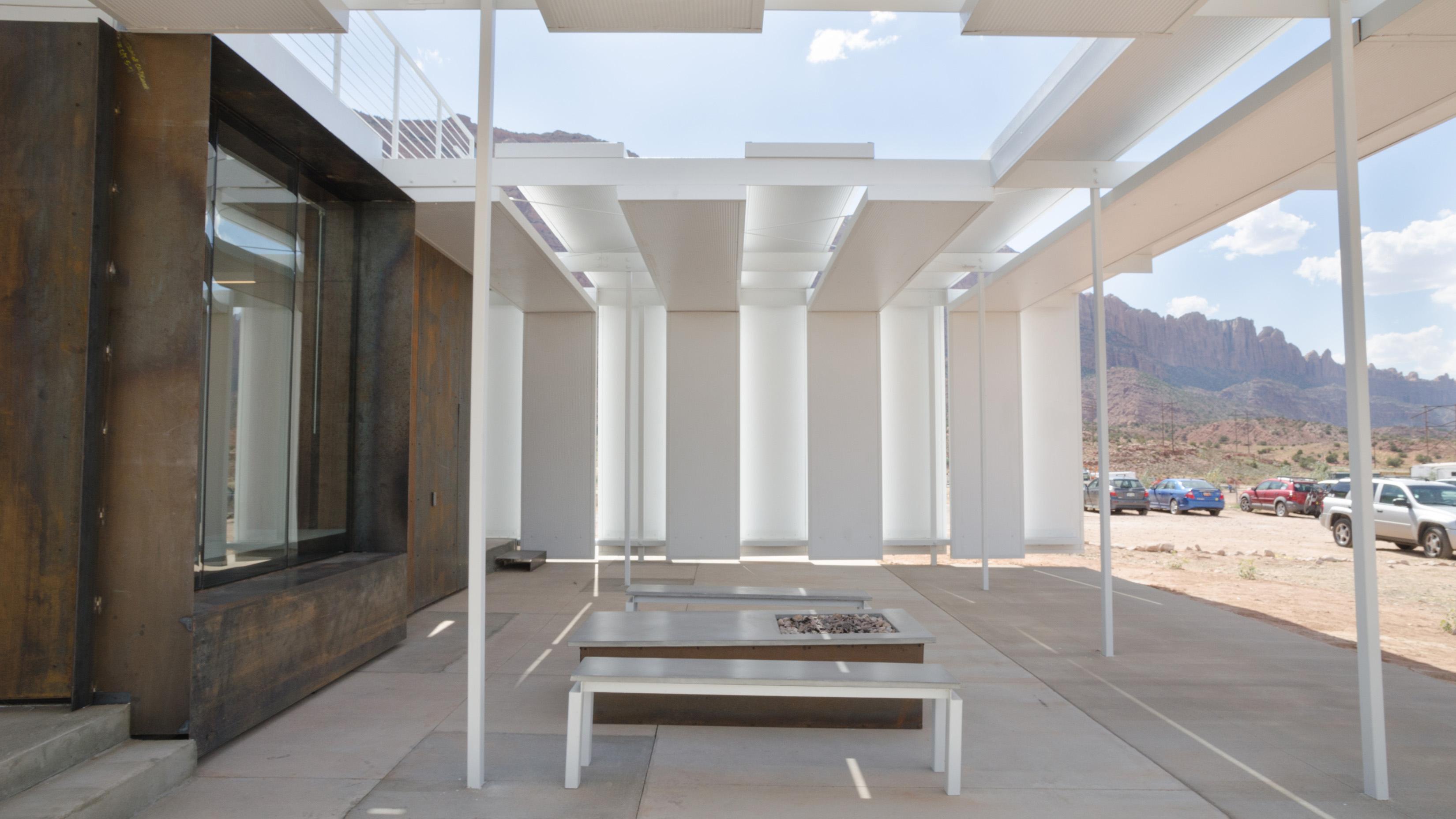
CONFLUENCE HALL
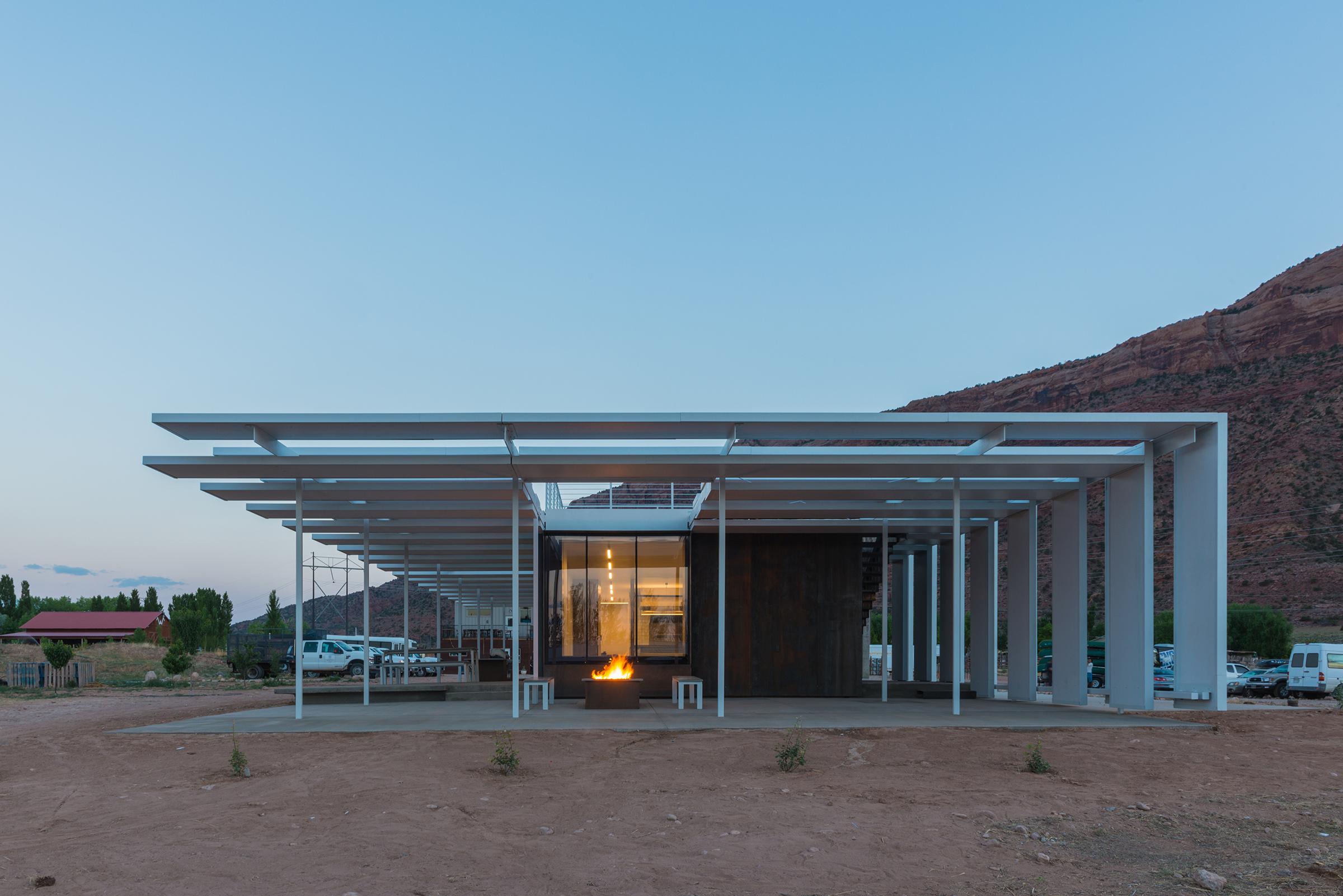
Proj. Type | Design Build, New Construction // 3,300 SF
Location | Moab, Utah
Date | January 2017 - May 2017
Instructors | Rick Sommerfeld, Will Koning, Andy Paddock
Student Role | Co-lead: West Wall Design & Construction | Lead: Client Communication
Professional Role | Assembled award submittals
Recognition | 2017 AIA Utah Honor Award
2018 ACSA Design Build Award
Published in Winter 2017 issue of ‘Modern In Denver’
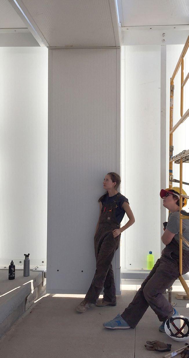
Myself, 25 other students & CBW instructors worked with the staff of Colorado Outward Bound to create a successful community space for their program. During the semester, design and prefabrication was done in Denver and onsite construction occurred during a week in March and a 3 week phase in May. My responsibilities included being a co-lead for the design and construction of the West Wall, which included both the 40’ long concrete wall, and the vertical continuation of the canopy panels.
Future
River
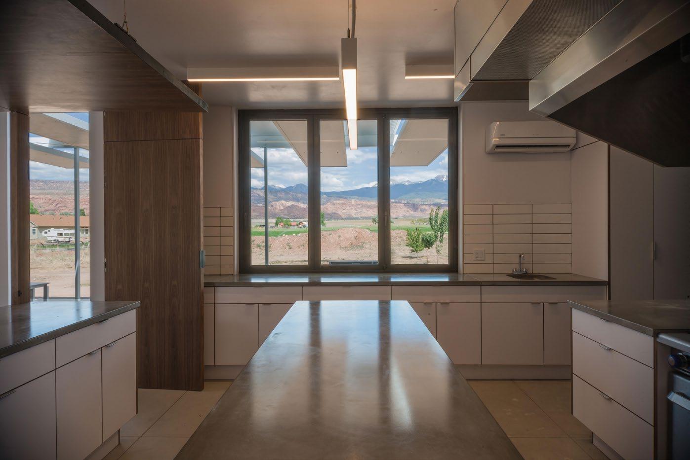
River Kitchen
Staff Housing
Staff/ Visitor Parking
Campus Entrance
Confluence
Garden
Compost
Orchard
Existing
2
3
4
5
6
7
8
9
10
11
12
WEST - BEHIND SCREEN WALL
WEST
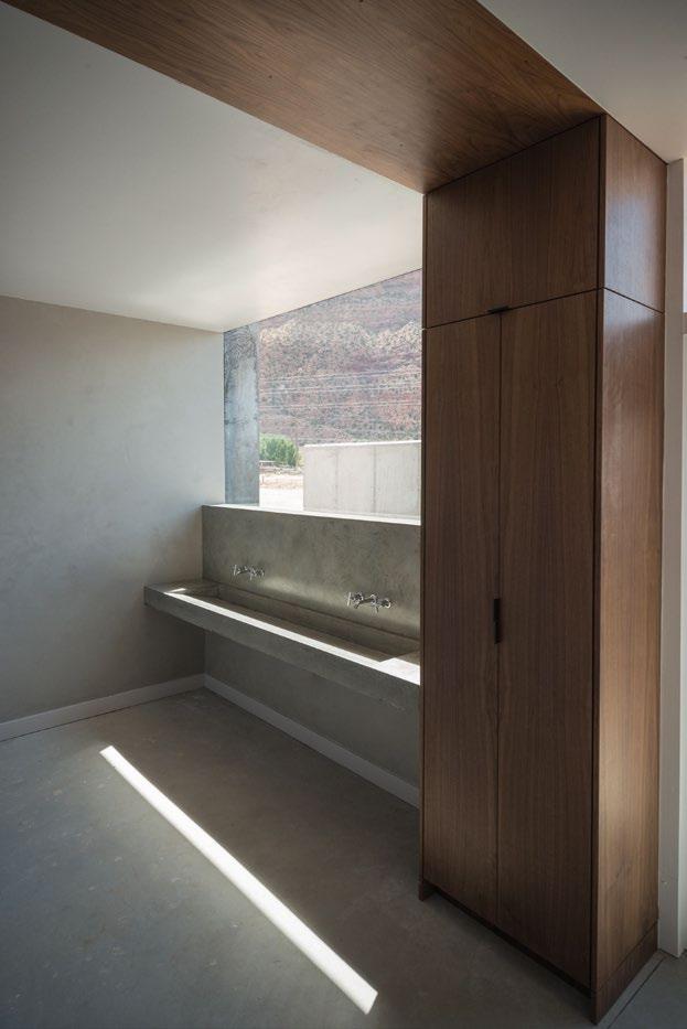
The program is organized from north to south into four zones: – exterior gathering, interior gathering, cooking, and “the spa.” The thresholds between each zone are divided by light and accented by walnut millwork.
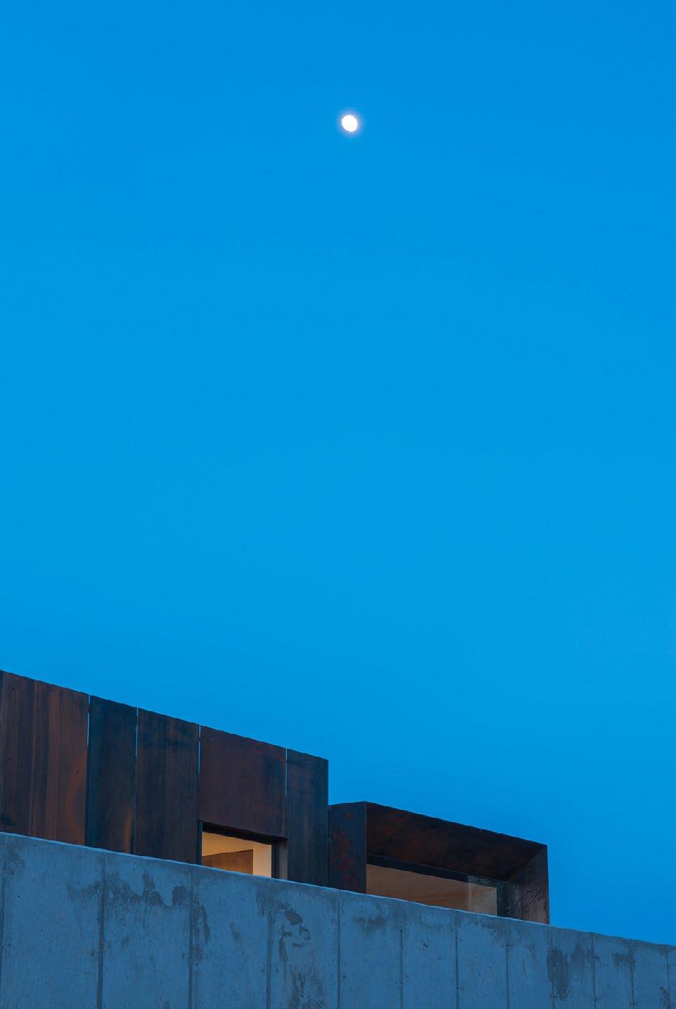
ROOFTOP DECK
A rooftop deck showcases the panoramic view of the La Sal Mountains to the east, and Moab’s Bluff’s to the west.
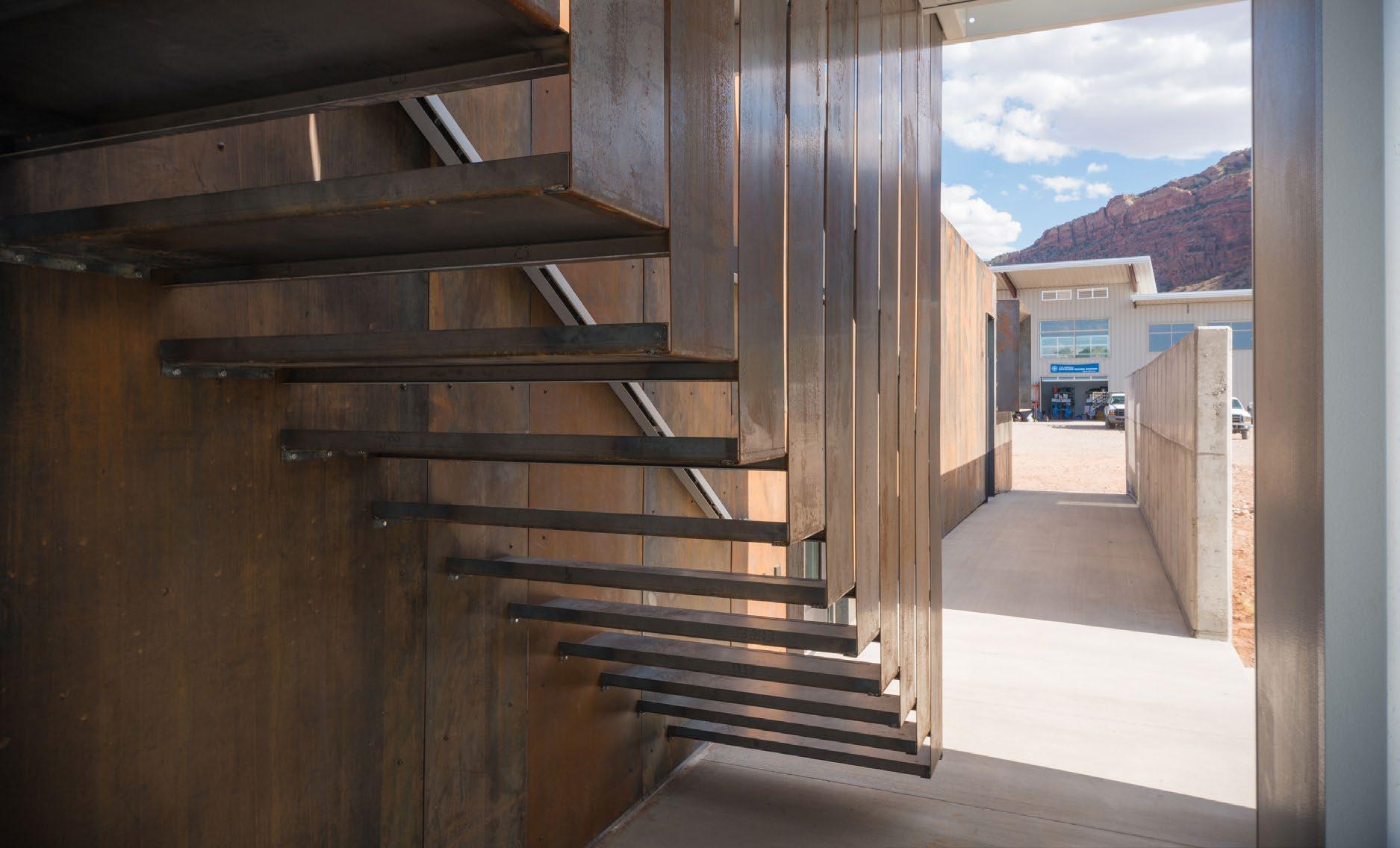
WEST WALL
A concrete wall serves as a barrier from the parking lot, creating a shaded walkway along the western edge of the building and directing views to the ridge.
CANOPY
Insulated metal panels were re-purposed using the leftovers from an unrelated project. The recycled material is utilized in creating a performative shade structure.
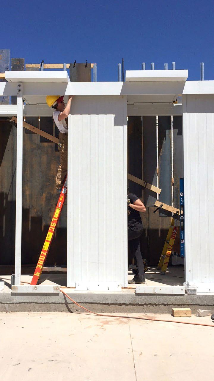
SIP WALL STRUCTURE
Structurally insulated panels allowed for speedy construction and desirable insulation properties.
STEEL CLADDING FOUNDATION
Rusted steel cladding relates the building to local context.
The foundation from the pre-existing trailer was utilized in the construction of the new building.
PRE-EXISTING TRAILER
A pre-existing double wide was sold to help finance the project.
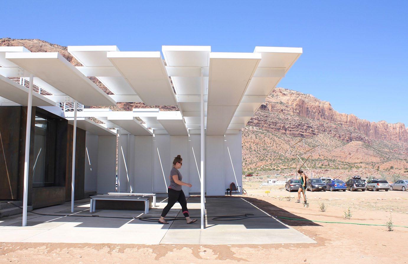
The canopy is constructed of four-inch thick insulated wall panels. The material was left over from a commercial building and scheduled to be discarded. The project recycles these panels, re-imagining them as large louvers for the patio opening to the eastern view of the La Salle Mountains. The inherent structural capacity of the panels is leveraged as a secondary structure to span large distances, minimizing the amount of steel sub-structure required. A grasshopper script was used to control the size of the structure, thickness and spacing of the panels, and the panel overlap - optimizing the canopy to allow for maximum sun penetration in the winter while restricting sun exposure in the summer.
DESIGN-BUILD TIMELINE
JANUARY, 2017
1
Removal of double-wide trailer.
2
Design of Confluence Hall begins.
FEBRUARY, 2017
3
Presentation of design ideas to client, and project approval.
MARCH-MAY 13
MARCH 18-25, 2017
Excavation of canopy support foundations.
Construction of main structure through SIP wall and roof panels.
Construction of concrete wall
Placement of glazing.
4 Prefabrication of building components.
CD’s to building department for approval.
5
MAY 13-JUNE 4, 2017
EXTERIOR INTERIOR
Erection of steel framework
Placement of canopy panels
Placement of vertical wall panels
Patio extensions poured
Installment of custom millwork and casework
Installment of rusted steel rainscreen
Construction of rooftop deck
Installment of electrical and plumbing fixtures
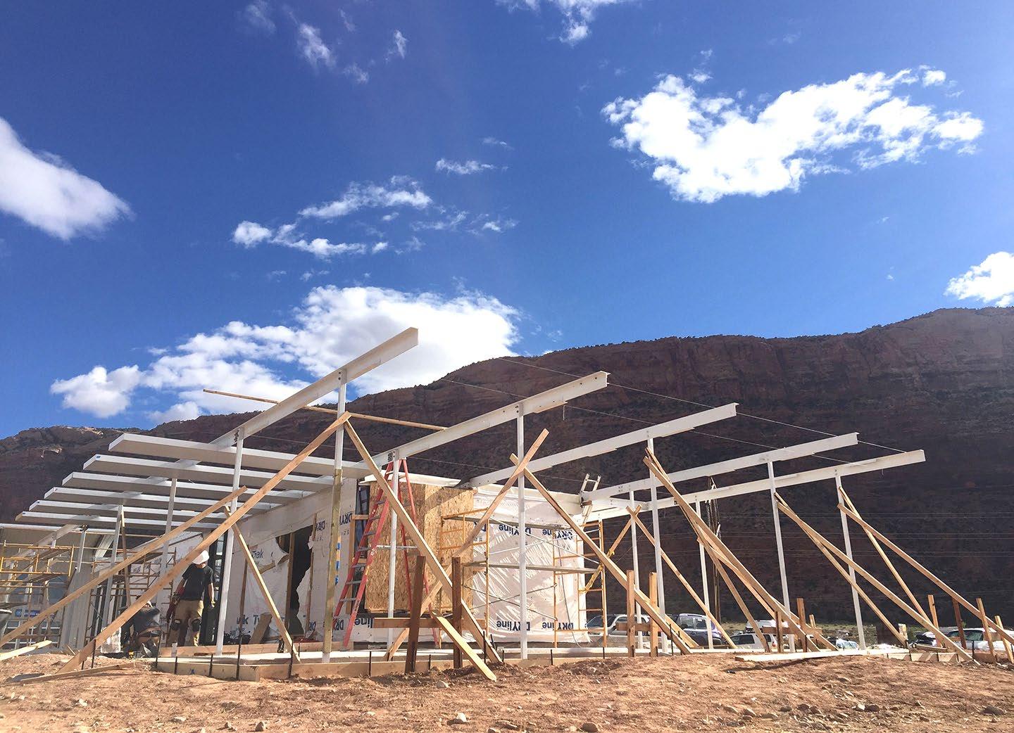
Framing of canopy structure & initial placement of metal panels.
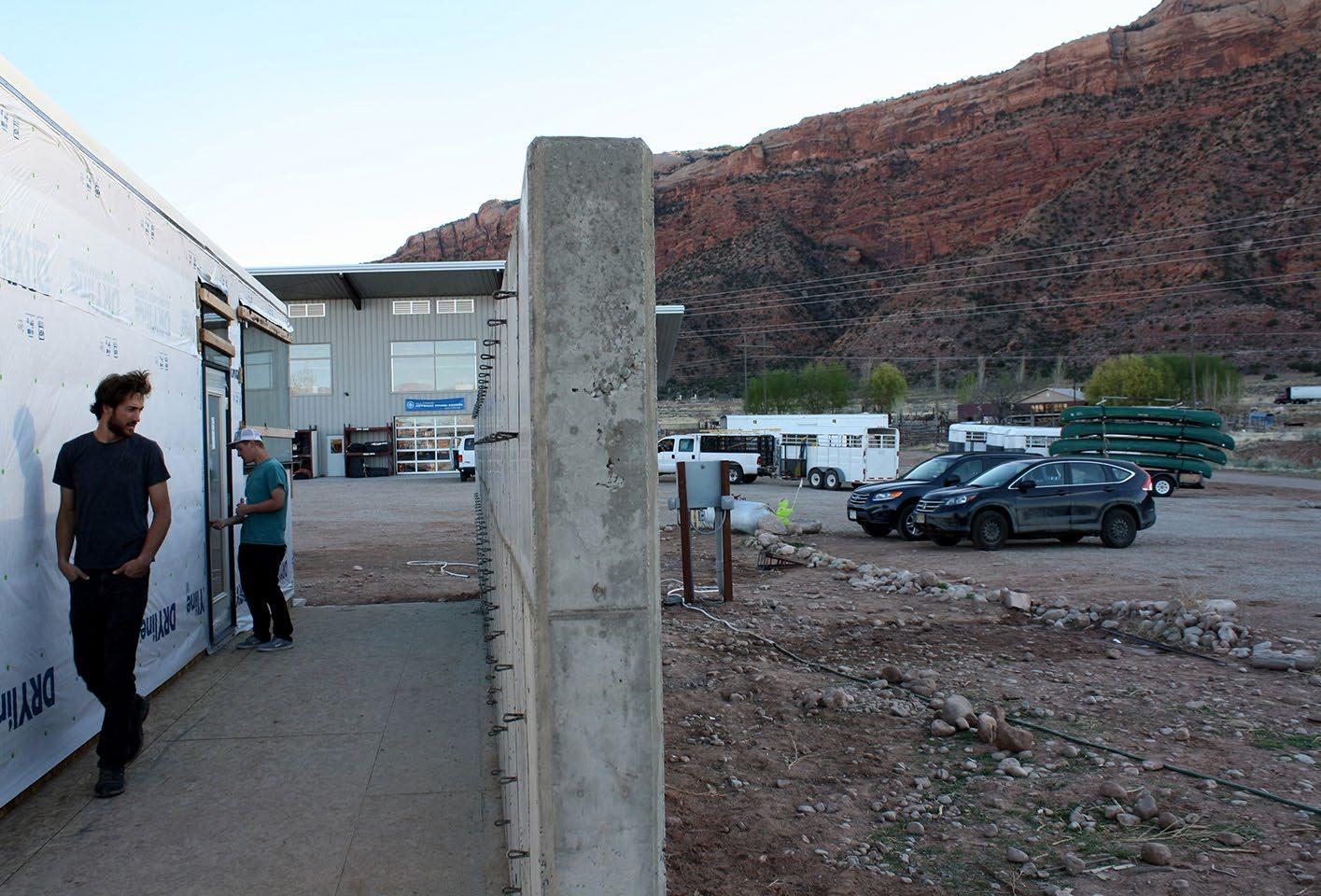
The concrete portion of the west wall accentuates the axis between confluence hall and the staff warehouse, while also acting as a separation between the hall and the parking lot.
Metal canopy panels turn vertically to shield the northern patio from the hot afternoon sun, and frame the main entry into confluence
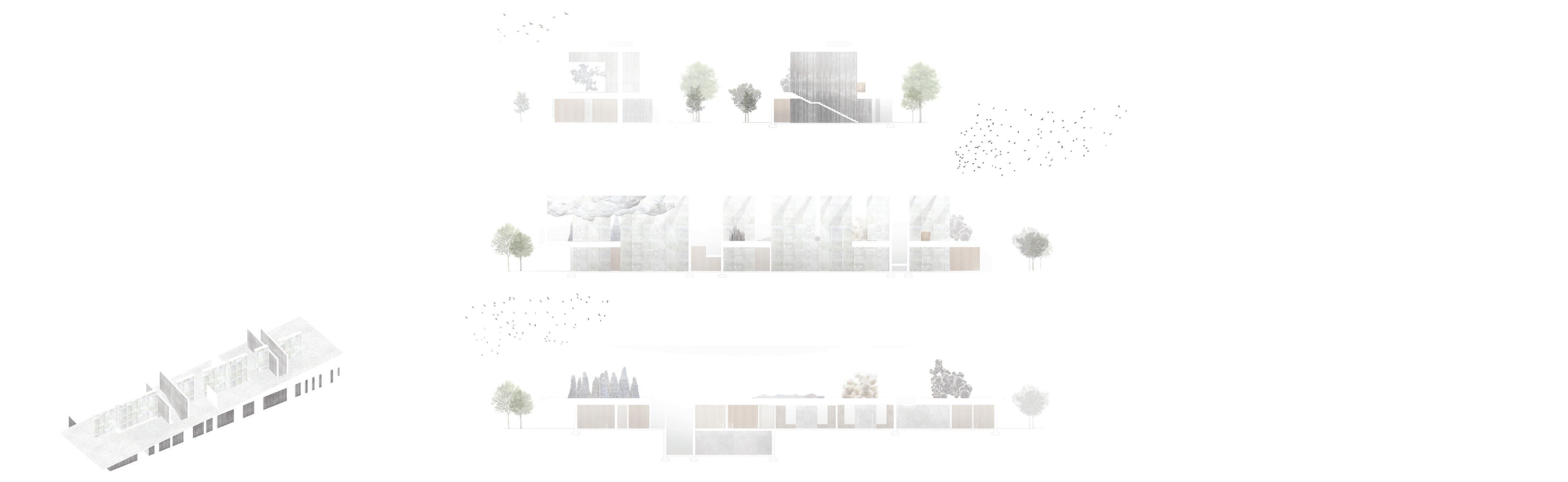
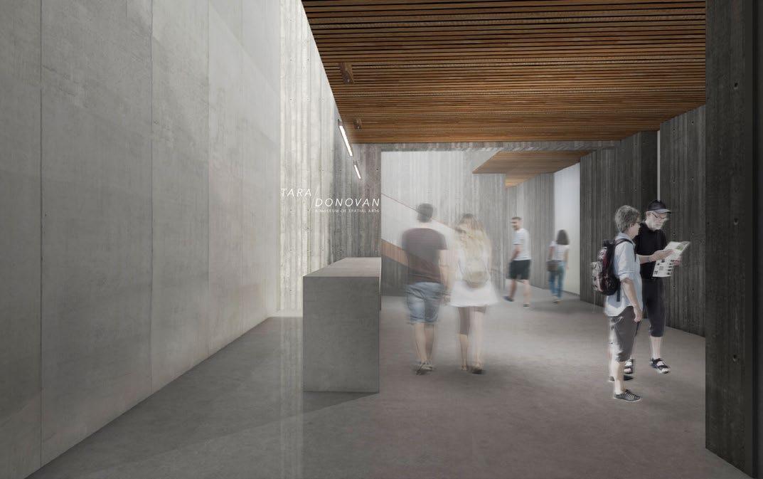
MUSEUM OF SPATIAL ART
Proj. Type | Tara Donovan Museum of Spatial Art
Location | Denver, CO
Date | Fall 2016
Instructor | Will Koning
Urban Figure Ground
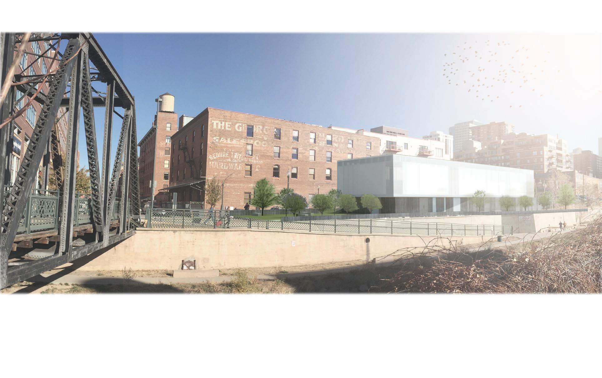
Lower Downtown Denver
Cherry Creek Edge
The site is situated along the Cherry Creek corridor, an active recreational path for the residents of Denver.
View Corridor Into & Out of City
The site is unique in its view corridor potentials both into and out of the site.
Bar Typology
Through a series of studies, a bar typology was chosen as the mass for the site, given its opportunities for the connection to context, and the sites physical constraints.
Program Separation & Siting
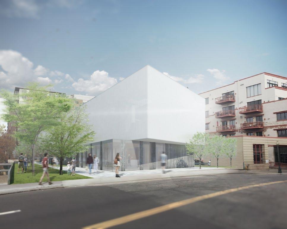
The bar was squeezed to allow for a main public entrance along Wynkoop. A gallery bar occupies the upper 2/3 of the structure, and is contrasted from the heavier base to highlight the program change.
Gallery Bar Rotation
The gallery bar is rotated slightly to provide cantilevered entrances while responding to the visual corridors into the city.
Datum Wall Addition
Within the structure, a heavy concrete datum wall was added to unite the upper and lower portions of the contrasting masses.
Transitional Space Subtractions Integration With Context & Landscape
To unite the interior and exterior program, two transitional spaces are subtracted from the mass to allow for circulation corridors.
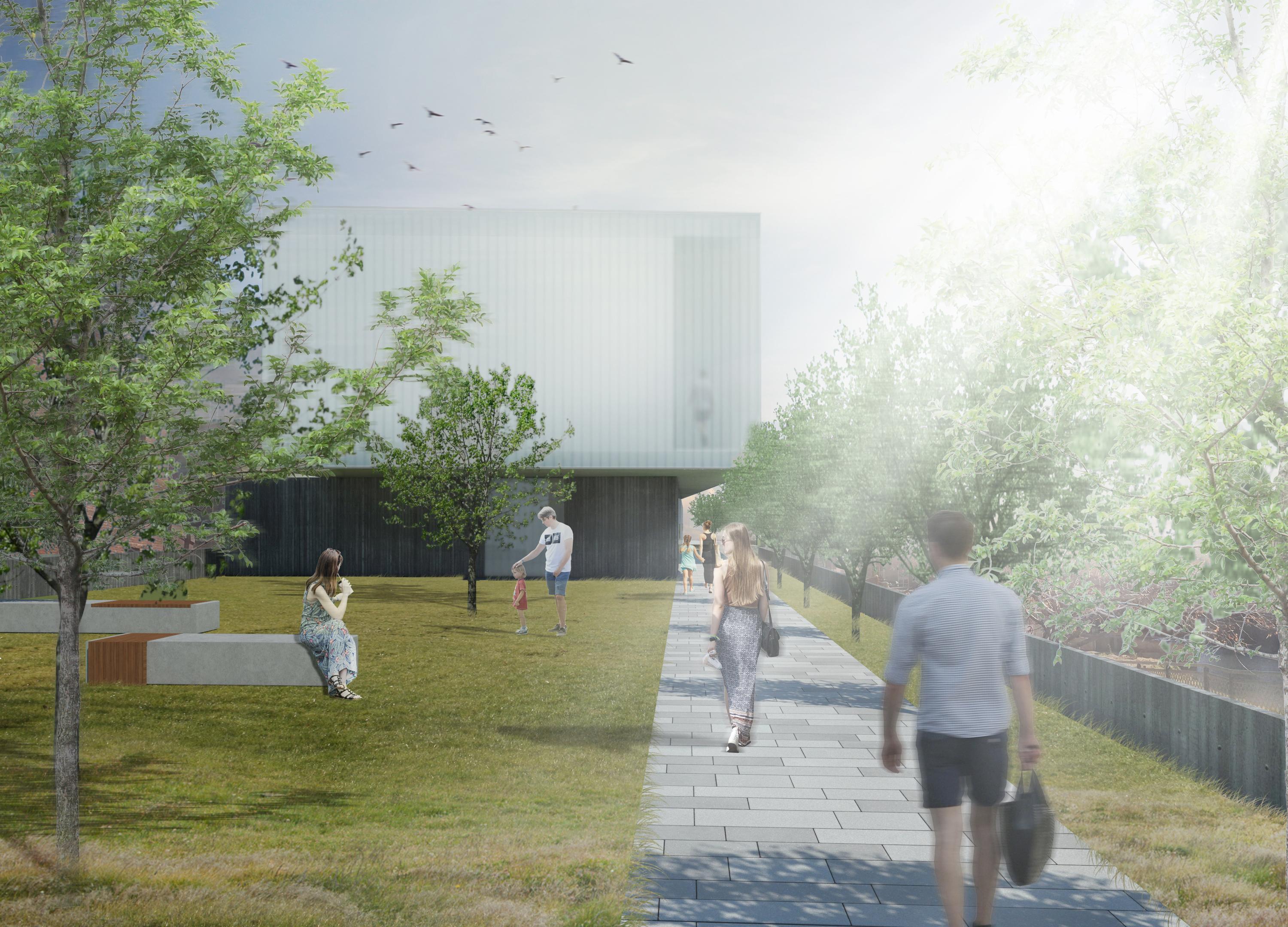
Two parklets are added, one placed along the main entrance to the museum, and the other along the south-western facade, adjacent to cherry creek.
1 Lobby
2 Gift Shop
3 Locker
4 Reception Office
5 Restrooms
6 Service Access
7 Reading Room
8 Workshop
9 Conference Room
10 Office
11 Community Room
12 Cafe
13 Kitchen 001
SECOND FLOOR SECTION
3
4
5
6
7
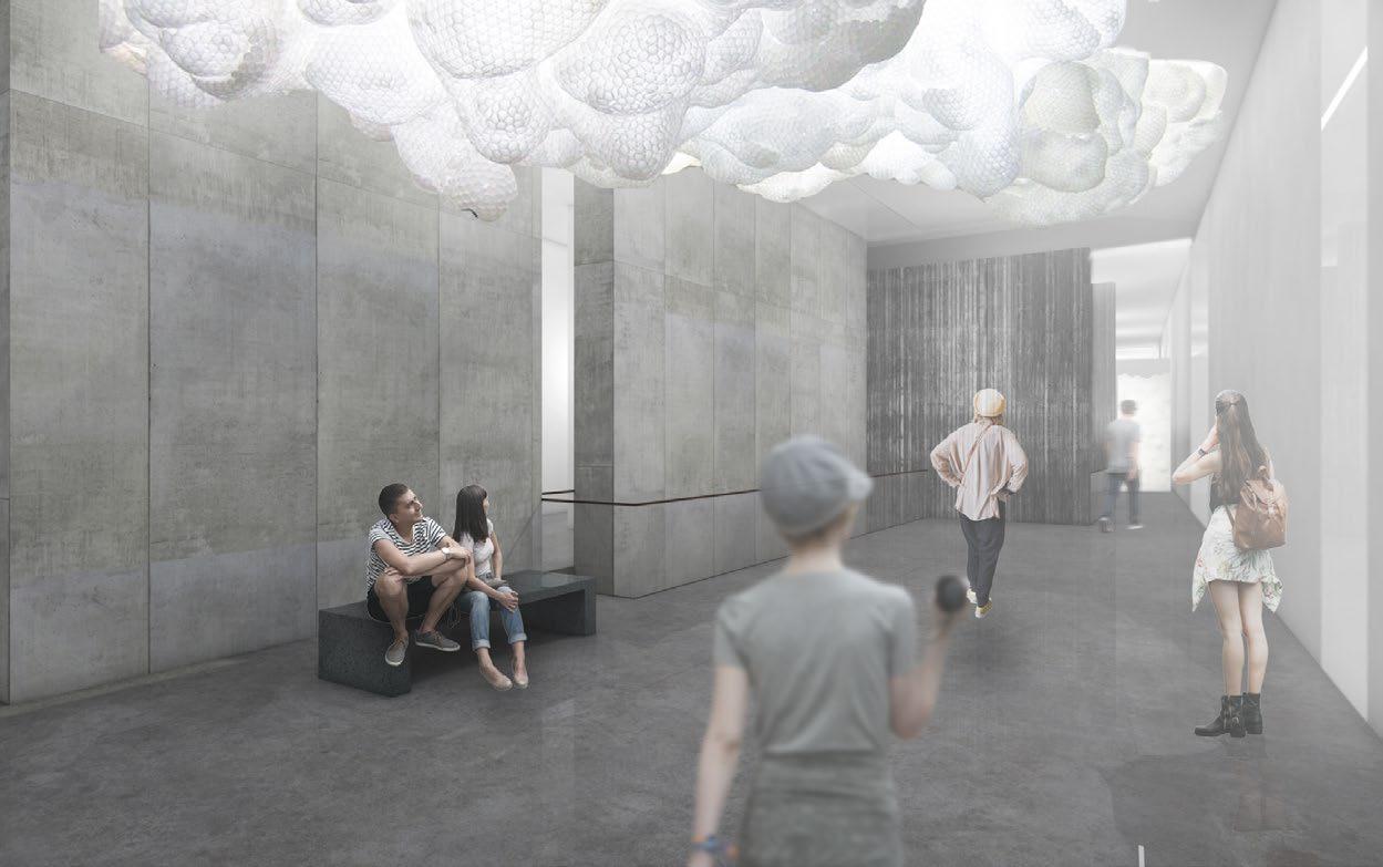
The Tara Donovan Museum of Spatial Art is meant to transpose the visitor into a unique environment for viewing art and to challenge ones understanding of space and context within their landscape. The building is set upon a unique site in the vibrant LoDo neighborhood of downtown Denver. Adjacent to the recreational corridor of Cherry Creek, the museum gives itself to the landscape as much as the interior, as a means to activate the public space and create a hub of social interaction within the neighborhood. The museum exists as a simple structure composed of two rectangular masses, slightly offset and rotated from each other, giving contrast and importance to the gallery space. Within the museum, the visitor experiences Donovan’s artwork within a light filled, bar. The gallery bar achieves its vibrant light through a double-skin facade, the outer-most layer composed of white channel glass, and the interior layer composed of polycarbonate panels. As the visitor moves through the gallery, they are undulating in and out of galleries of various sizes- while moving in between and around a concrete wall, anchoring the gallery box within the lower mass and the surrounding context.
Skylight System
14
15
Exterior Facade System
12
13
Interior Facade System
9
10
11
1
2
3
4
5
6
7
Gallery Organization
Cafe entry approach from Wazee st.
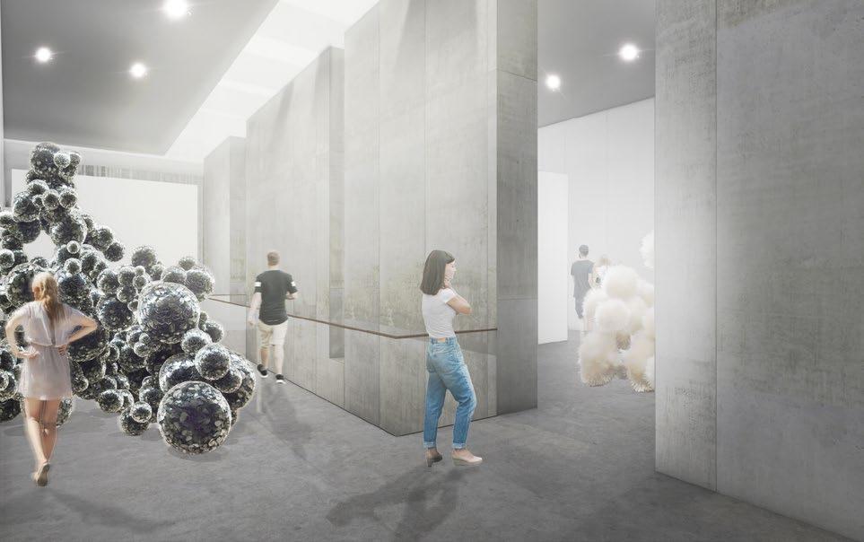
Gallery space

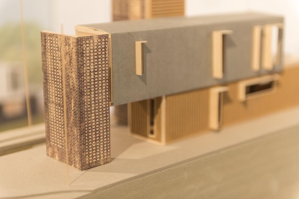
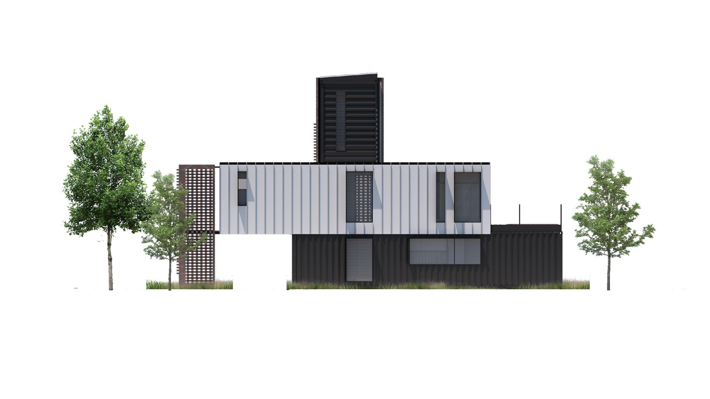
2523 16TH STREET
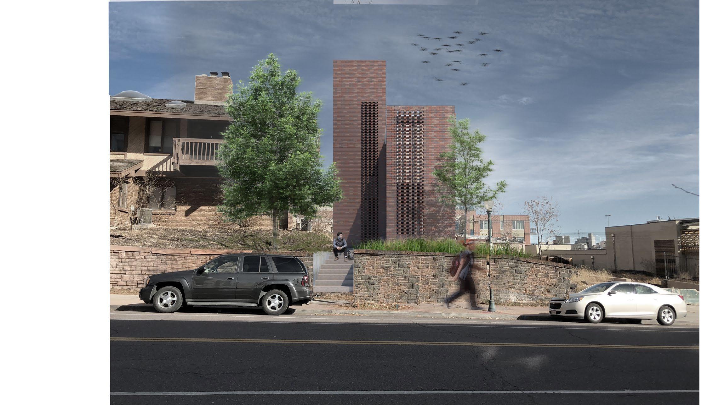
Proj. Type | Small Home Shipping Container
Location | Denver, CO
Date | Fall 2017
Instructor | Julee Herdt
1
2 3
4
Solar control in winter & summer months
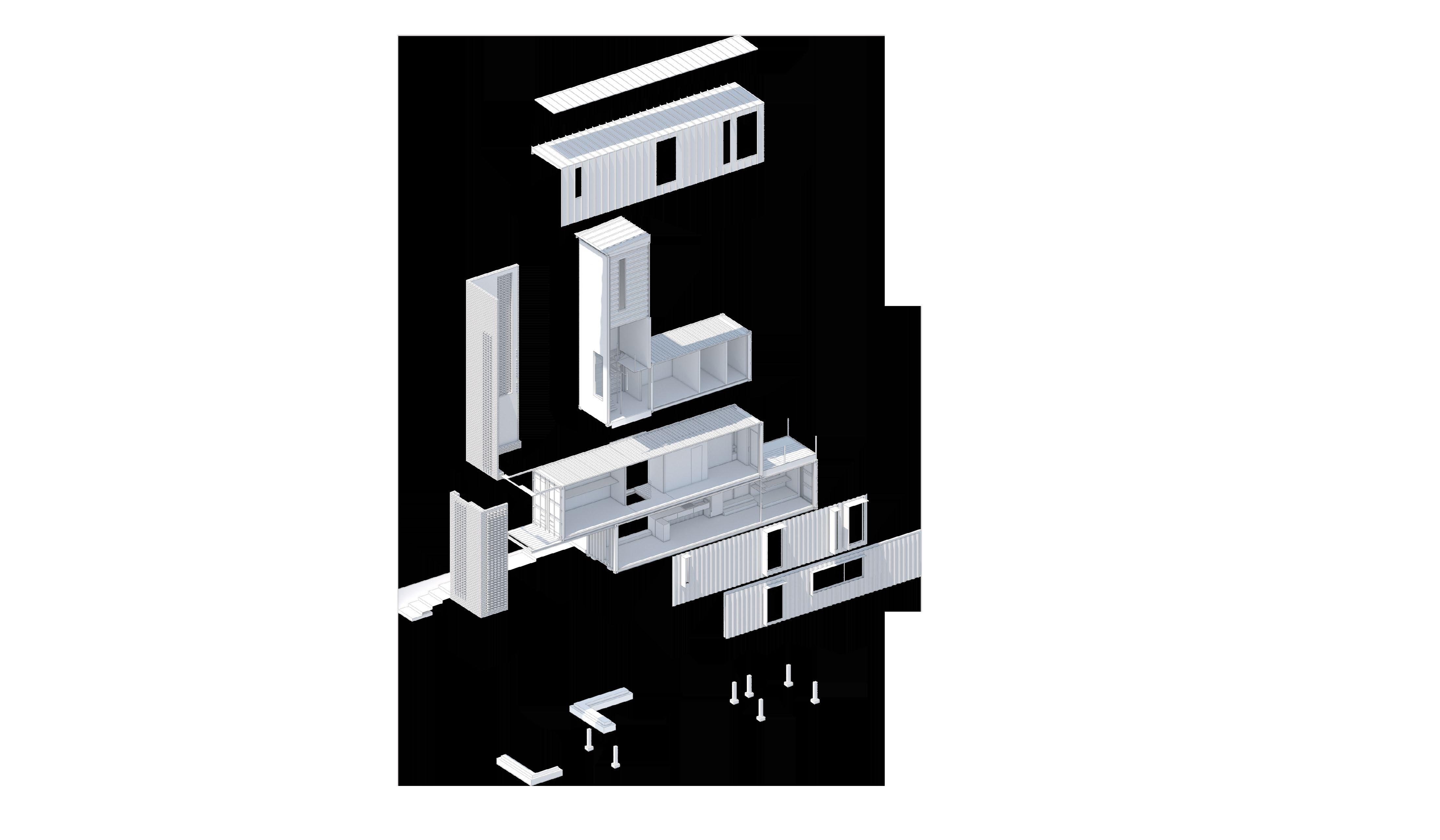
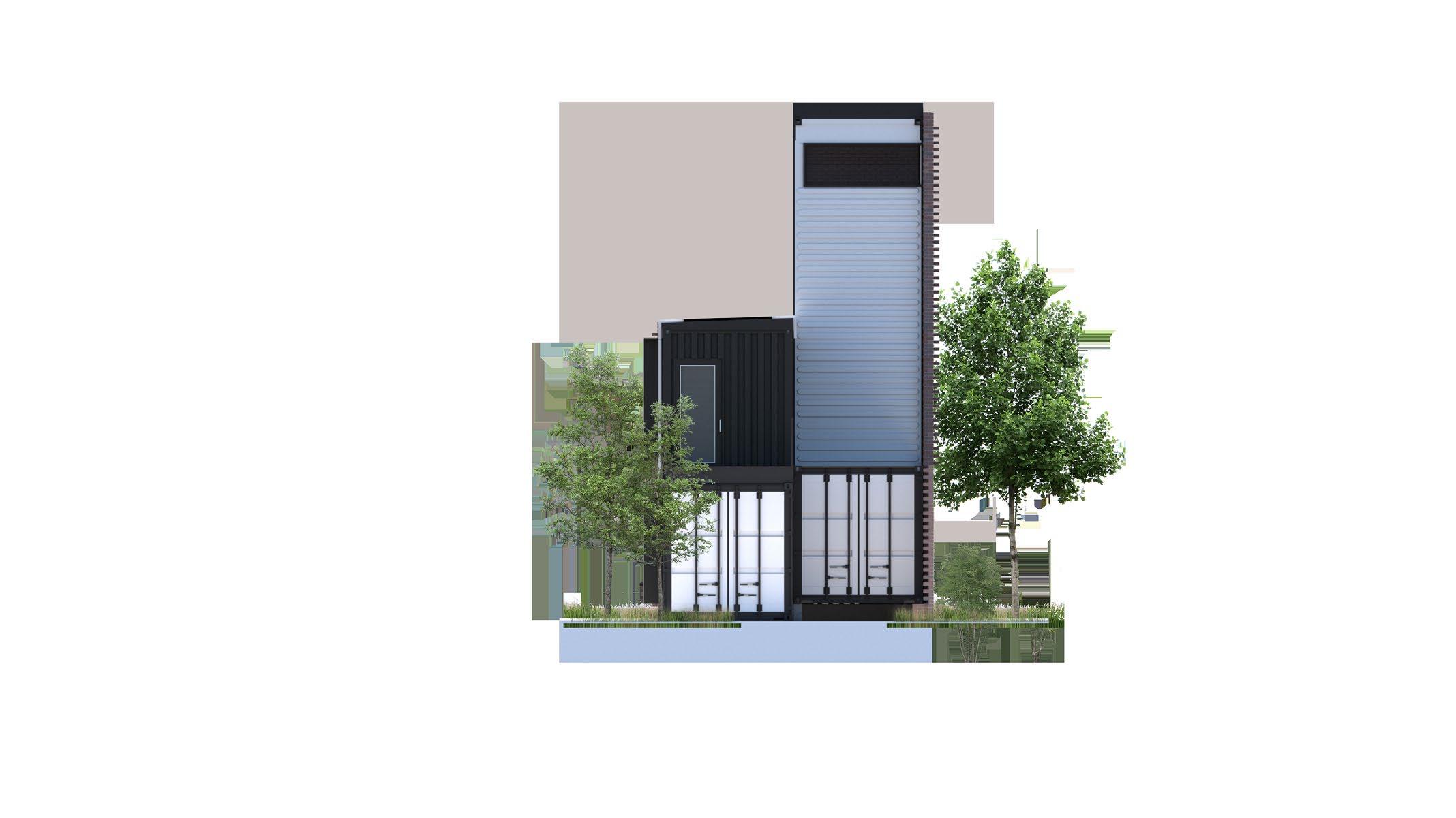
4 SHIPPING CONTAINERS
High mass & night ventilation
LOCATION
Walking & Biking to Downtown Platte River, Union Station
Walking & Biking to Highlands
Automotive Transportation
Views to Downtown Denver
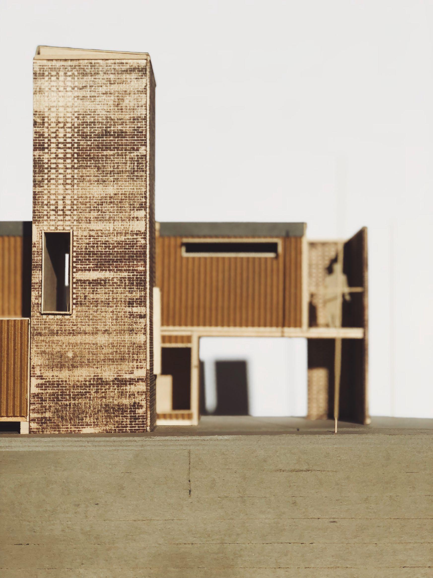
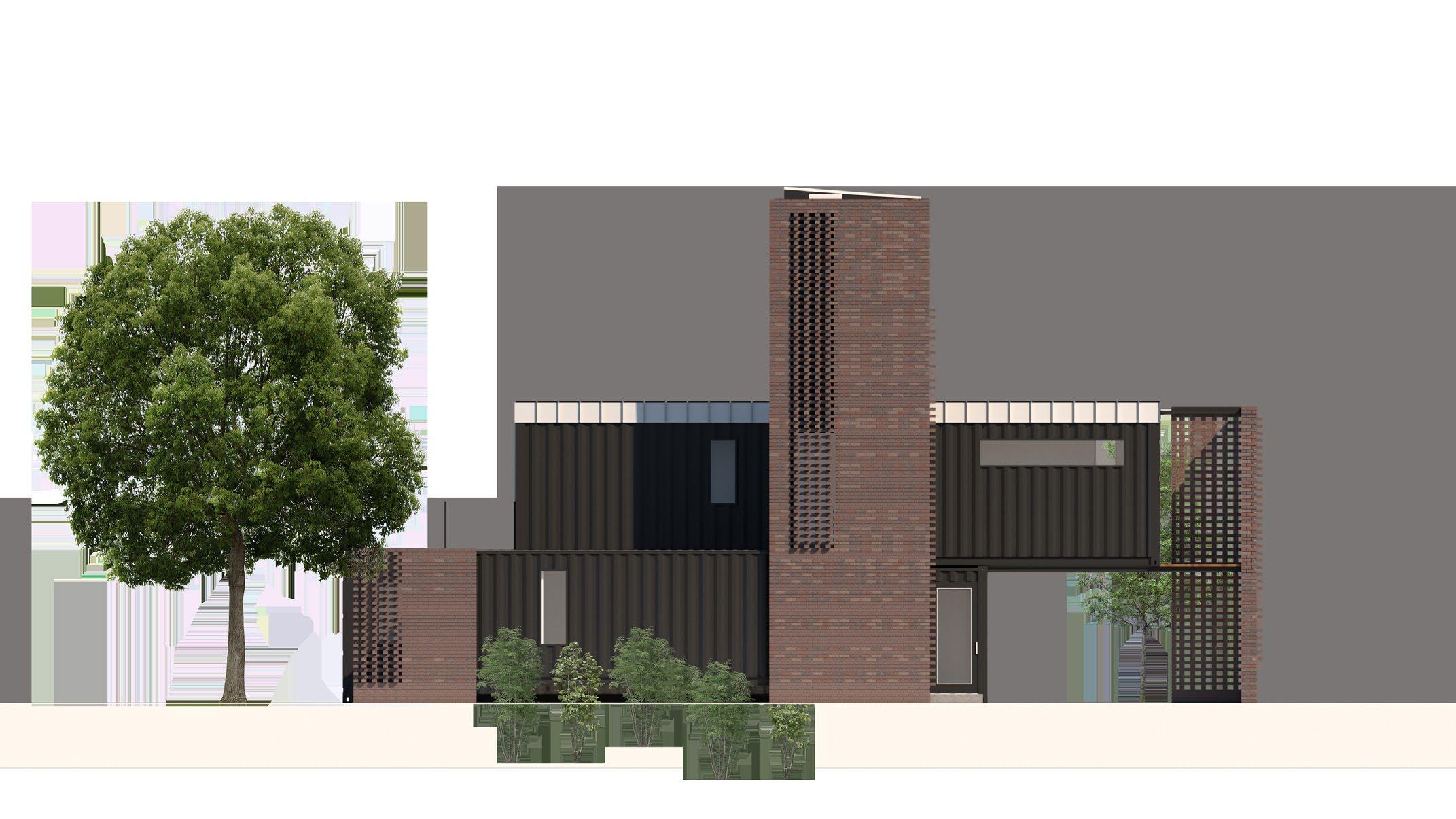
The home is designed as a small residence for an architect, 780 sqft max, 2-bed, 2-bath, energy efficient, using shipping containers as the main construction module combined with structural steel systems, a brick screen facade, and BioSIP’s.
The residence was designed around passive strategies for heat retention and natural ventilation. Night flushing through stack ventilation works in conjunction with solar control in summer months to achieve a design that is less reliant on mechanical systems.
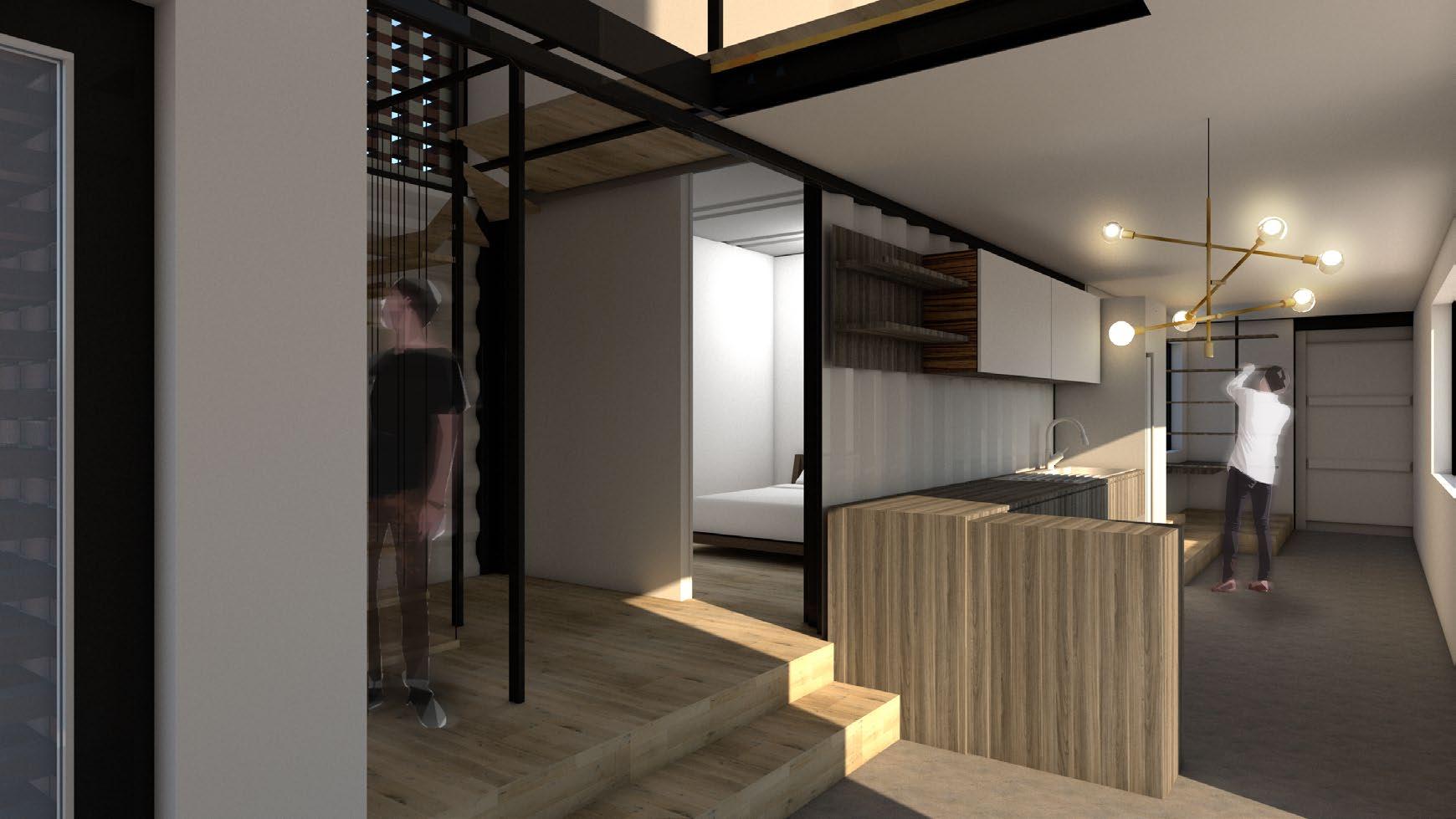
SECOND
1
A vertical 30’ shipping container serves the dual purpose of vertical circulation and providing stack ventilation, passively cooling the home.
As the top of the container is heated by the sun, the temperature gradient creates a pressure differential, forcing hot air out of the top window.
2
Studio lighting is accented through a north facing picture window. The studio is adjacent to a private screened terrace.
3
Second floor container is cantilevered between the lower container and a reinforced brick wall.
Warm-board is used as a modular radiant heating system. The radiant system will be zoned off into three sections; living/dining, bedroom, and studio.
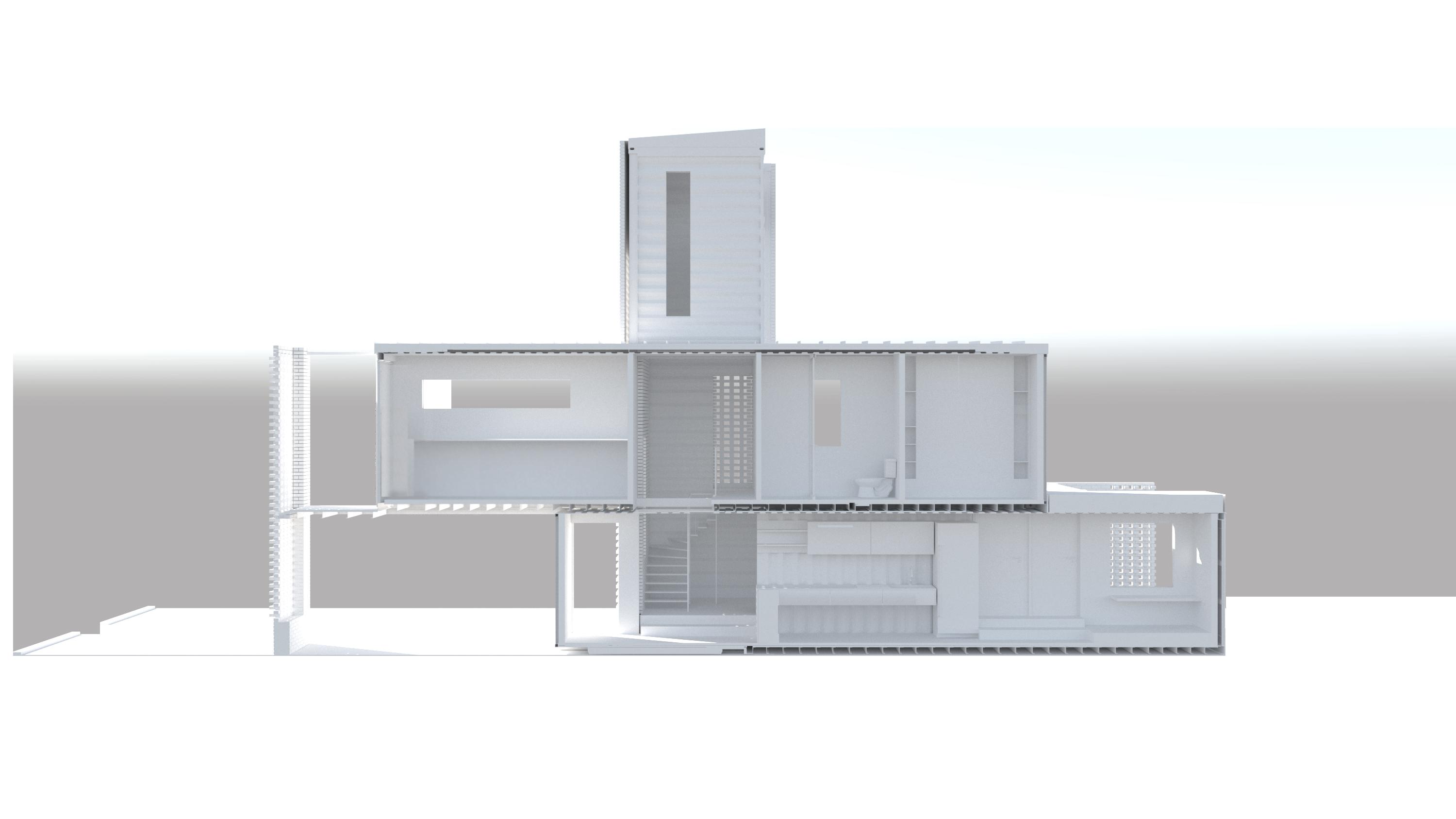
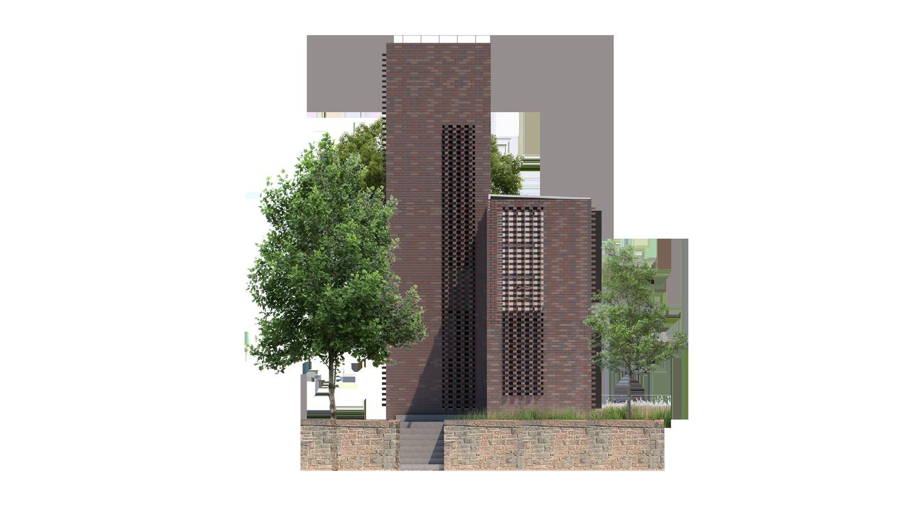
EAST SOUTH


 01 Foundation
04 On site construction of brick screens
05 Bio-Sip interior insulation
06 Standing seam rainscreen +shadow box installation
02 Installation of ground level containers
03 Installation of vertical and cantilevered containers
01 Foundation
04 On site construction of brick screens
05 Bio-Sip interior insulation
06 Standing seam rainscreen +shadow box installation
02 Installation of ground level containers
03 Installation of vertical and cantilevered containers

 Slip dowel rod through holes in connection tab


 Wall partition prototype


 2x2 x 6’ rusted steel angle
1/2”x1/2” Acrylic tube, frosted
voice controlled LED light
rusted wide flange
1”x1” vertical support angle
2x2 x 6’ rusted steel angle
1/2”x1/2” Acrylic tube, frosted
voice controlled LED light
rusted wide flange
1”x1” vertical support angle

