
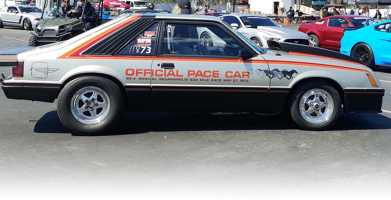

With Christmas and New Years behind us, it’s really just a few months before we will be racing again, and Project Pace Car Race Car has been moving along well. In the December issue of RPM, we introduced the parts we’d be using to wire the car, and over the past month or so we got down to business with the job. In this issue, we will discuss the ignition installation process and then outline the steps taken to fire the fresh engine up from a DIY standpoint. Most readers will be well versed on this, but for newcomers it’s as good a time as any to go over the basics as we all have to start somewhere.
After getting our budget engine build between the frame rails of the
Pace Car and installing all the supporting systems, we needed to wire the car’s electrical system. The easy way to do this is to separate each system that you will require.
1. Starting system, which consists of the ignition-on and crank.
2. The cooling system, which in our case, consisted of a water pump and cooling for engine and transmission.
3. The fuel system, which included two fuel pumps.
4. Transbrake.
5. Nitrous oxide activation.
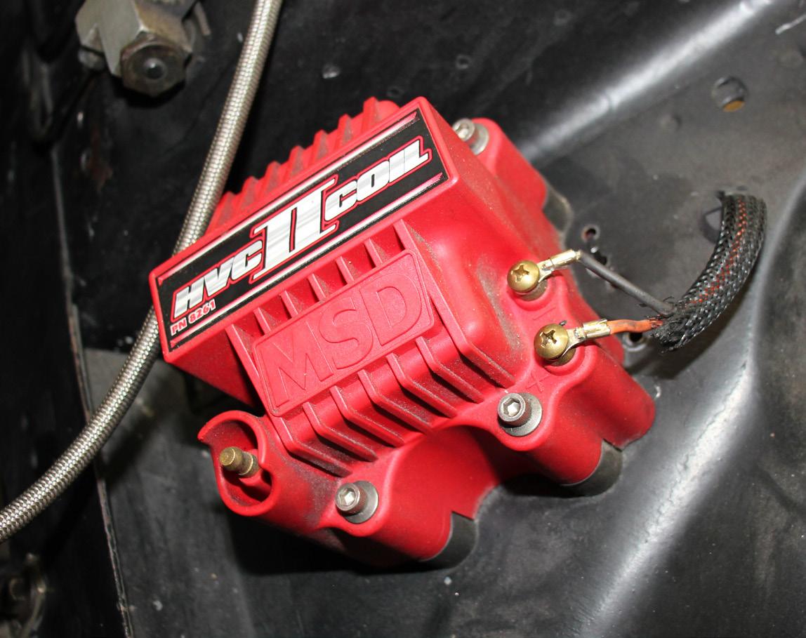
6. Ignition System - MSD Grid, supported by an MSD crank trigger and a golf tee (locked out) distributor.
BiroEach system draws a certain amount of power, so you need to match wire gauge size to each system’s requirements or draw. The use of breakers, fuses and relays will all make your decisions easier. We generally plan, then plot the electrical system on paper, gather all the required parts and then get to it. Remember, a race car sees a lot of vibration so every connection needs to be tight and solid. When using solder, make sure you use heat shrink, and always cover your positive connections with non-conductive shields. There are many wiring diagrams available from the parts manufacturers, so take advantage of them as they know their product requirements best.
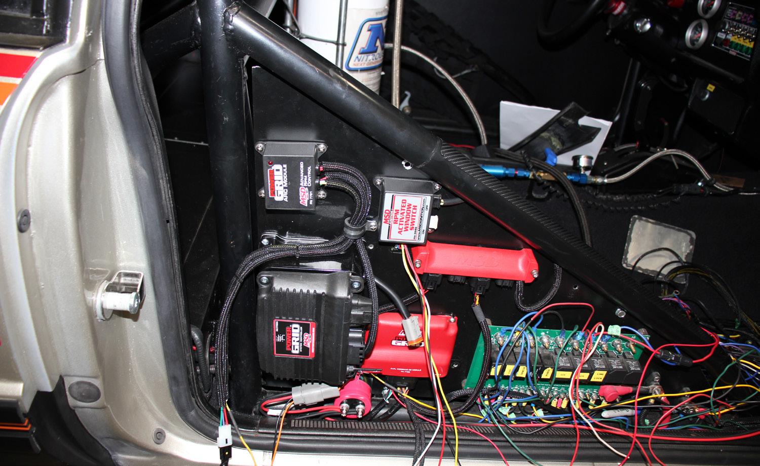
This was the PCRC interior before the MSD Power Grid install. As our ignition board was already laid out for another older version of MSD and fuel injection parts, we had to really think outside the box to physically install all of the new components. Making the ARC and dual wide band tuning modules fit on our board ensures easy tuning and maintenance and keeps everything neat and tidy in one location.
Using MSD ignition for so many years, it was honestly a no brainer that our ignition would be nothing but MSD. We chose their Power Grid system after researching the product and simply asking others who use in it in similar applications about their experiences with it. For us it was definitely the right choice. First, the total cost of our investment is affordable for most, even entry level racers. It also makes sense as it is a modular system, meaning it is expandable
by simply adding modules based on our future needs. I can hardly wait to use the ARC Module which should be the ticket for traction control with our small tire application, especially on some of the non-prepped surfaces we may visit.
That brings a story to mind. It was mid-October back in 2003 while sitting in the lanes in my small tire, small block, nitrous drag car that ran high 8s at the time. I was three cars away from my elimination run and there it
Once the old equipment was removed it’s a matter of pulling and collecting all the wires, making sure everything is sized correctly and rerouting as necessary. It’s a bit more complicated when you are working with an ex-street car that has so much original wiring left in it.

was, snow falling on my windshield. EEEK! Thoughts of doom started going through my head, man I wish I had an ARC system back then!
With the Power Grid, if you are accustomed to using an ignition “box”, get ready to enter a whole new world as it is so much more than “just” an ignition system. The data logging capabilities and expandability of the system are fantastic. Our setup is pretty basic, but we also added a
wideband 02 system module to monitor and tune our air / fuel ratios.
We ran through each part with a description in our last article and also discussed how we simply added modules to our Power Grid 77203 System Controller box to meet our needs and budget.
Next, we’ll recap each module that we added, factor in any associated equipment and provide a basic costing breakdown, as well.

Total Retail Cost from leading parts suppliers should be approximately$2854.15 plus distributor.
Part #7720
The Ignition ...................... $540.95
Part #7730
The Power Grid Controller $486.95
Part #7555
The Inductive Spark Plug Wire Pickup ................................. $117.95
Part #7761
ARC Module ...................... $661.95
Part #7766
Dual Wideband O2 Module
$559.95
Part #7740
CAN-bus hub .......................$89.45
Part #8640
Flying Magnet Crank Trigger
$396.95
Golf tee distributor (locked out)-swap meet .... $20-$50
In our case we had a used brand x Billet distributor $50.00
We might be a little high on our estimated cost, but we wanted to work from published retail. In the end, for an ignition system with this much flexibility and control, we are quite happy with the investment of under $3000. We should never need to upgrade, but at the same time have the

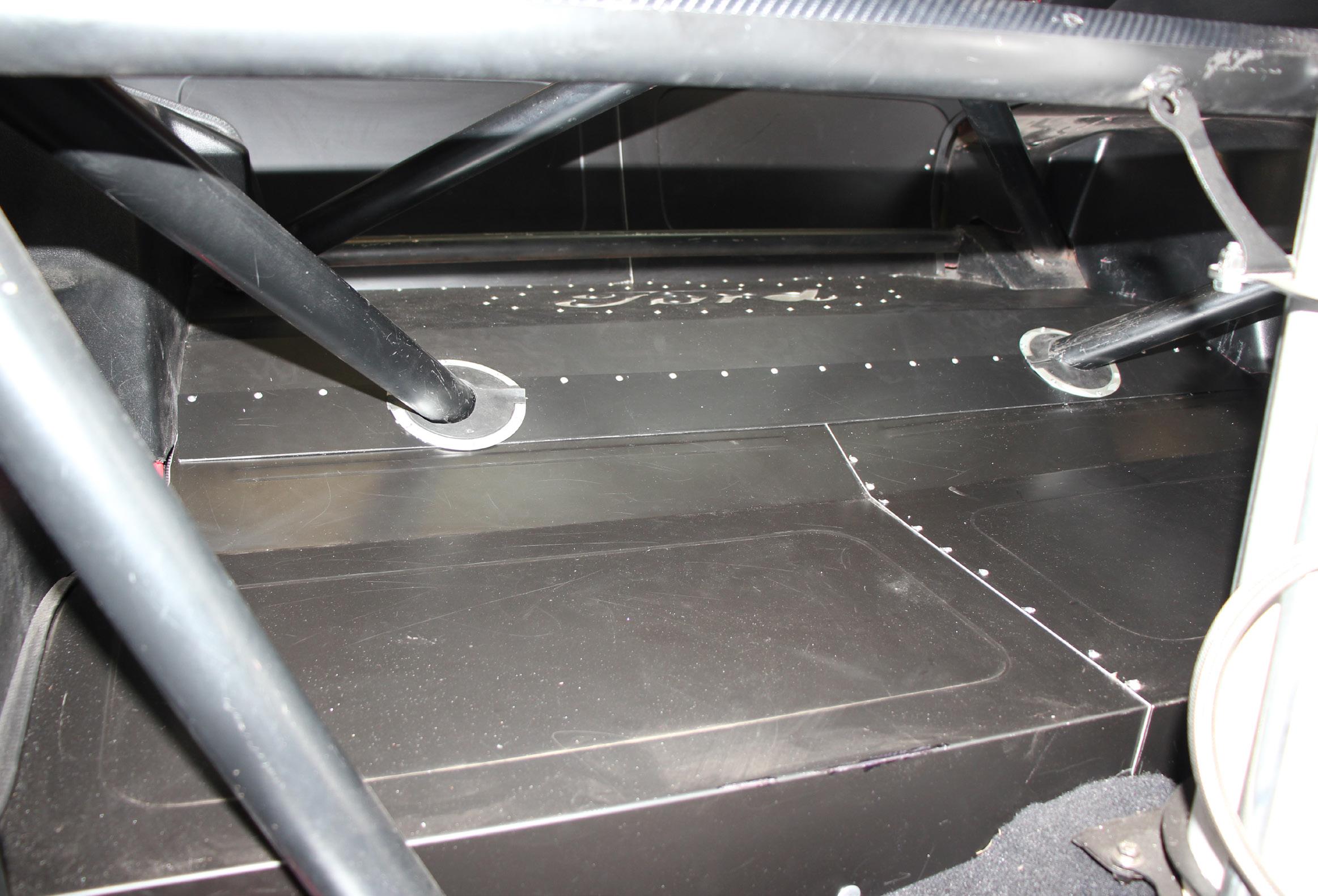
Finding places to run wires before you start is wise. In the PCRC, the back seat area had been modified and covered with tin work, an excellent place to run wires out of sight, but because it was permanently fastened in place, the wires had to be carefully fished through. Having a decent wire fish tape in your toolbox is always a good idea.
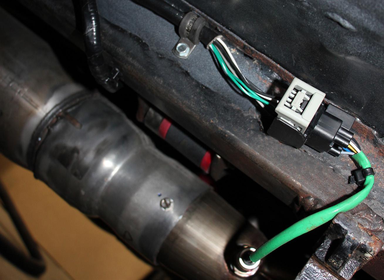


A wideband 02 using a weather tight connection was installed under the floor of the Pace Car. Be mindful of wiring harness placement due to the extreme heat of the exhaust. The pre-made harness from MSD made it easy to install the dual wide band system.


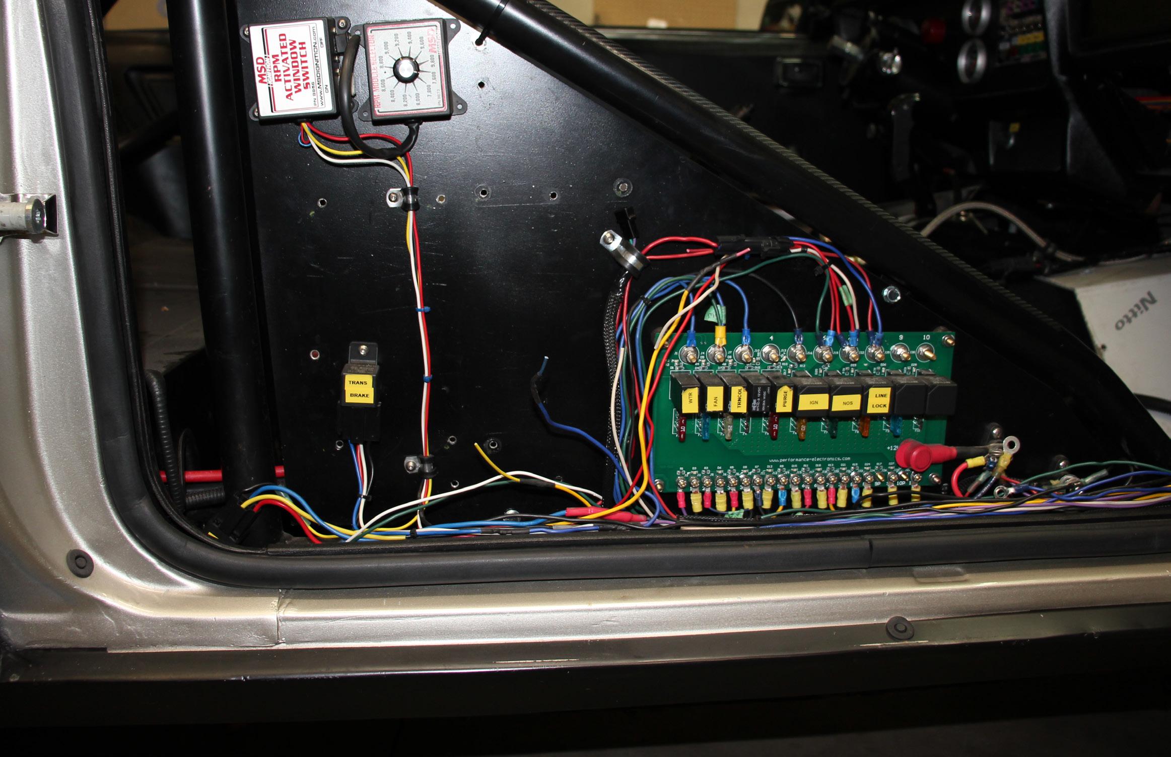
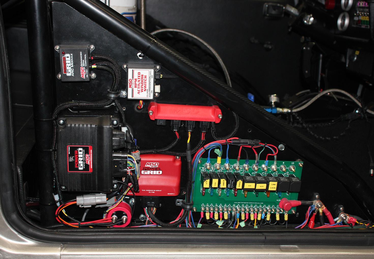
A nice clean finished product. It was tight but we made it all fit onto the existing board. Be sure to label everything and it doesn’t hurt to keep a map or schematic of your wiring in the car. Now we’ll move back under the hood to finish up there and soon be able fire this budget beast up.
When you see oil pressure, it is wise to rotate the engine by hand a couple of times to make sure the oil gets everywhere it should.
Making progress. The main components are installed, just need to route and clean up the wiring. The planning process is very important to wiring all components, as some may need to be wired to common connections. Components can share grounds and some, depending on draw, can share 12 V power supplies.
ability to add to the system’s capabilities through simply adding modules. After wiring was completed and tested, we pulled the rocker covers and set the valves for the first fire up. After the valves were set, we dropped some oil in the engine and hand primed it with a tool and drill. Be mindful of the direction your pump turns to pressurize the system. When you see oil pressure, it is wise to rotate the engine by hand a couple of times to make sure the oil gets everywhere it should. With the priming tool removed, it is now time to drop in the distributor.
First, be sure that the oil pump drive shaft is installed and centered. I am sure you are wondering why I called the distributor a golf tee earlier. Well, it’s because in this application, it is dead. Our crank trigger tells the ignition when we need spark. There is no ignition in our distributor. It is there to do one thing - distribute the spark. Establish which post on your distributor cap is going to be number one and mark it. At that post, drill a ½ -¾ inch hole through the top of a spare distributor cap, close to the number one post, inline with the cap coil connection post. The hole is to

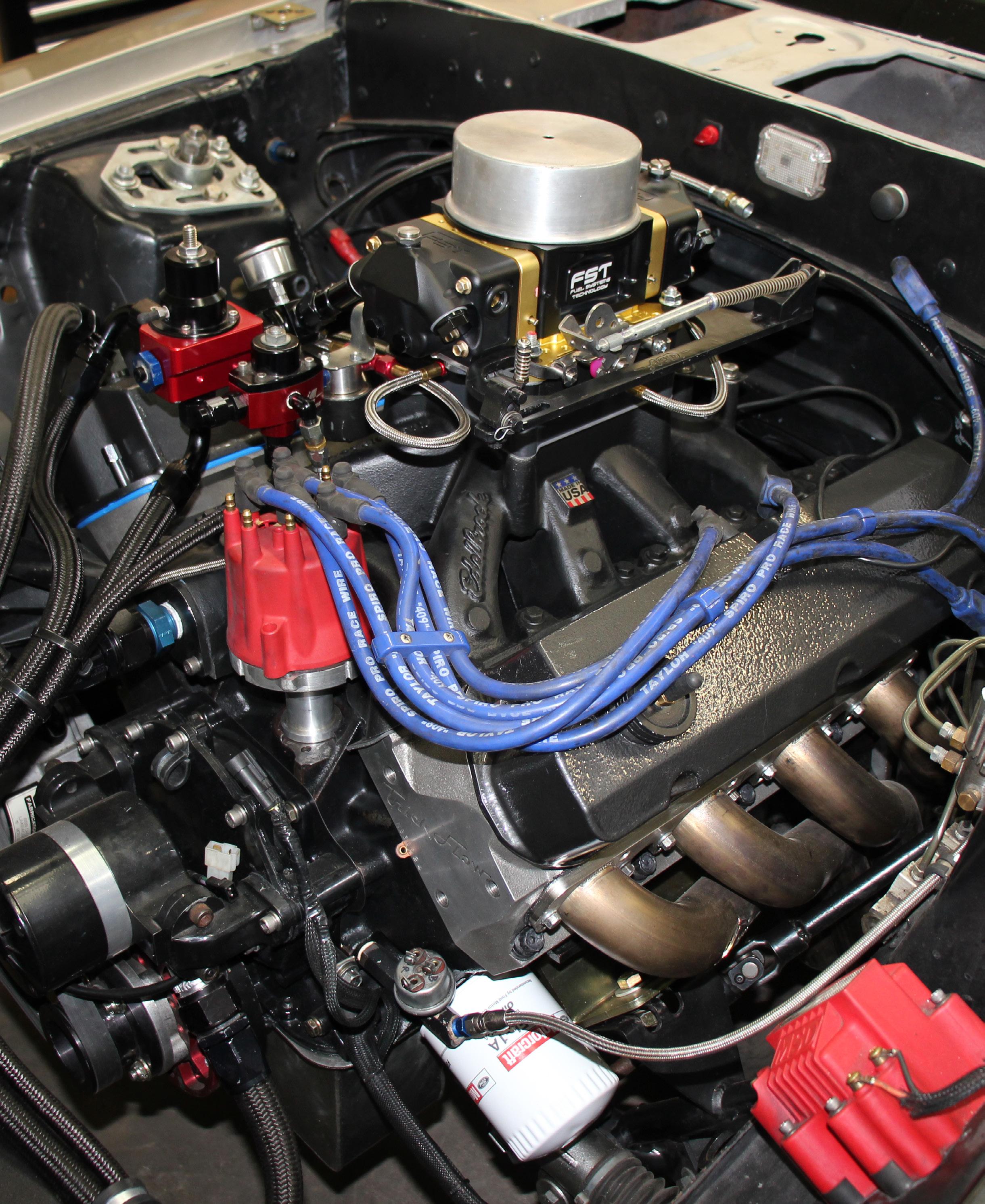
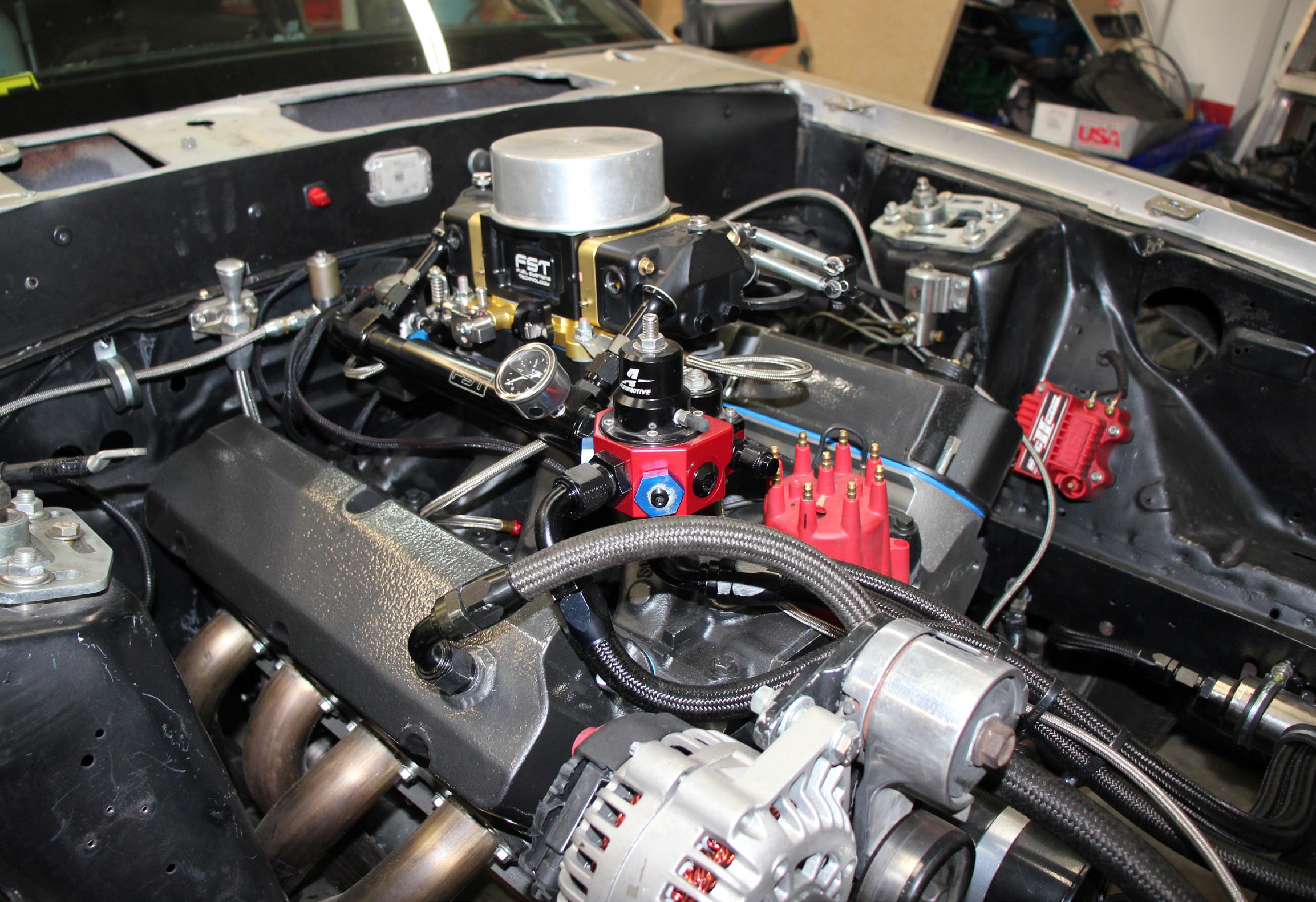
Moving back to the engine bay, with a few more wires to go we are almost ready to start the engine.
see the rotor spin under the cap while running. I like to place a white mark on the rotor and a white mark across the hole, the same way you would mark a timing mark on your crank damper/harmonic balancer. Rotate your engine to around 20 degrees before TDC (top dead center) on the compression stroke. The crank trigger pickup should be near a magnet, if not, adjust the crank trigger pickup. Be sure your trigger air gap is within specification. Drop the distributor in and align the rotor to the number
one post as you slide the distributor home, and be sure to engage the oil pump shaft. Your ignition timing is now roughed in.
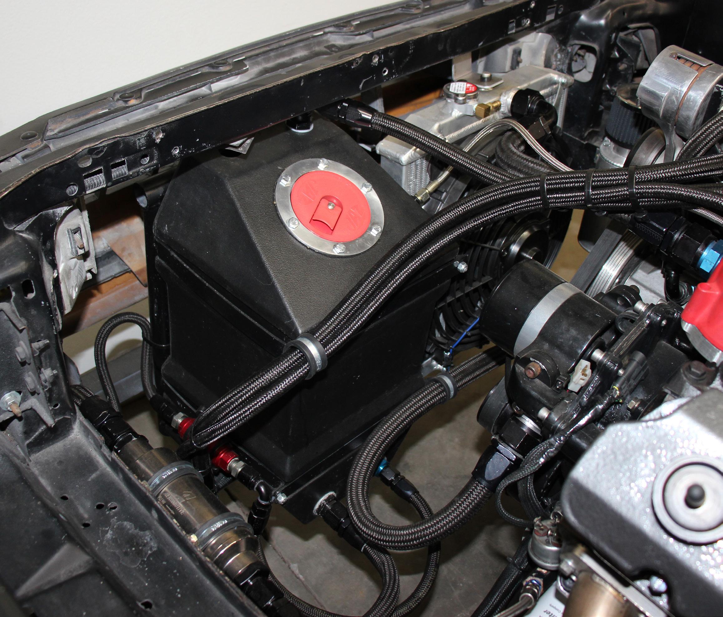
Next, we’ll move on to the fuel system. Be sure that you fill your tank with the correct fuel and it is essential to purge the system of any debris before the final installation onto your fuel log. Check for leaks.
Now, to the coolant system - fill and test for leaks. At this point, if you haven’t already done so, ensure that your battery has a full charge.
Turn on your electric water pump to purge the system of any air. If you are running a mechanical pump, keep the cap off for air to escape from the coolant system until you see a little heat in the engine. Top it up and cap it while running. Keep extra water nearby. Now double check your battery charge, hook up a timing light and you are ready to go!
With the fuel system primed, using quite a few shots of fuel, turn on the ignition and the engine should fire with the roll of the starter. After start
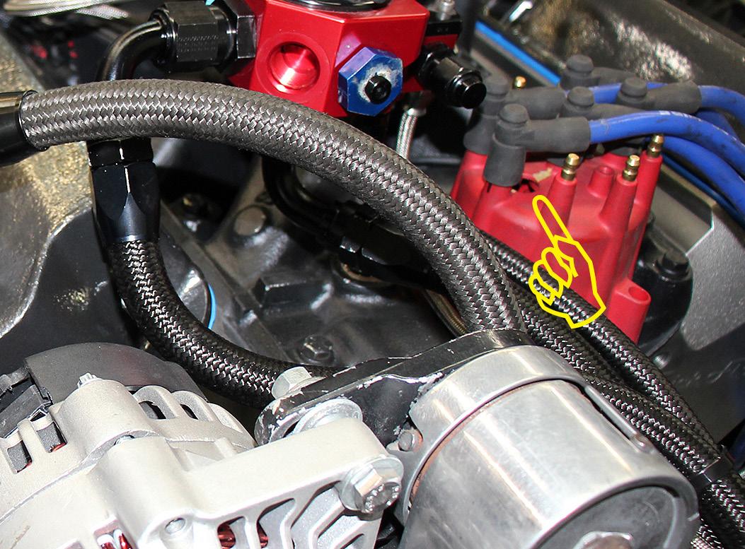
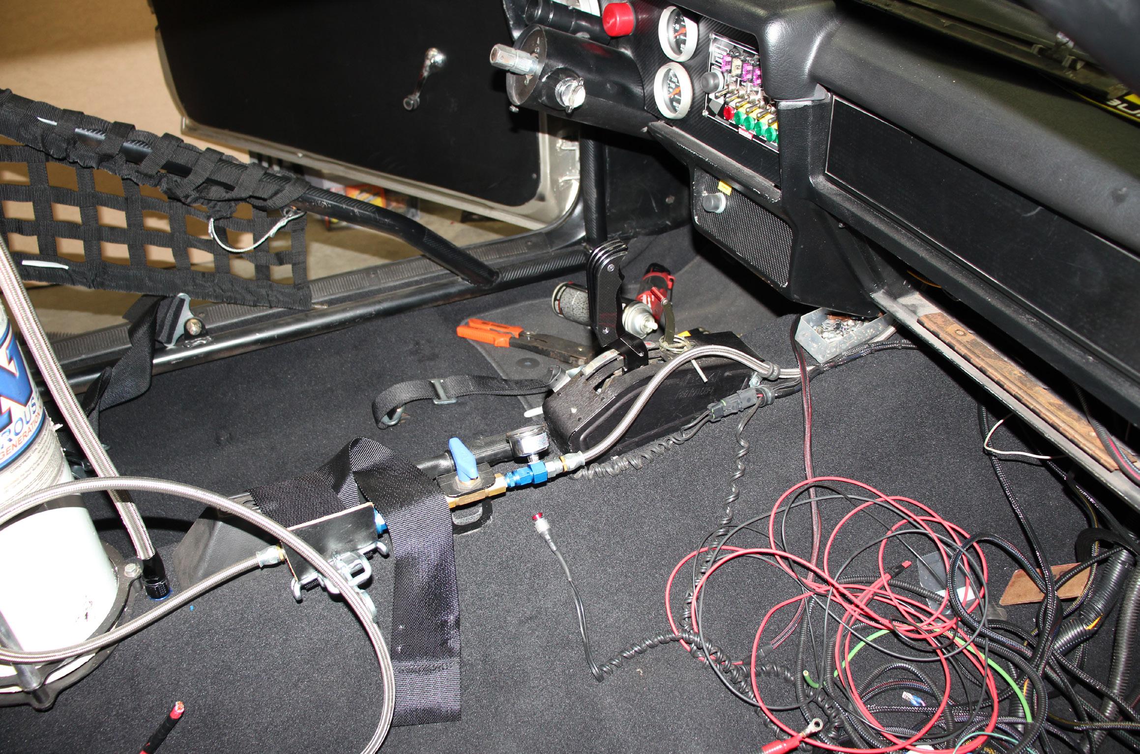
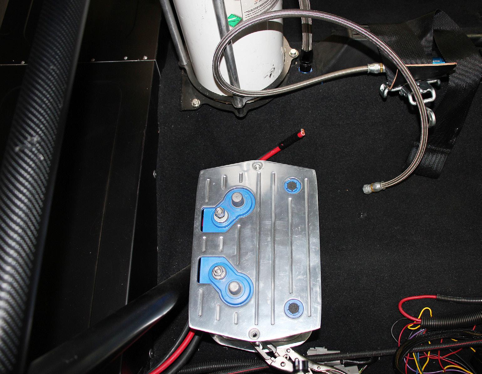
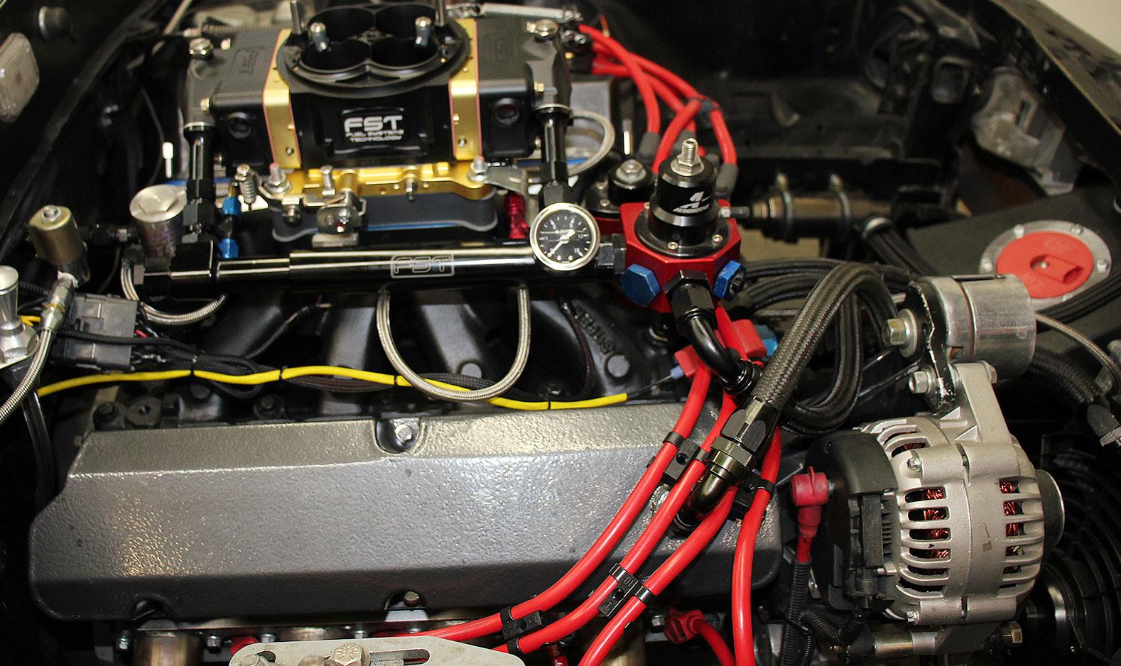
A close up of the nitrous oxide system wiring - It’s hard to see, but behind the fuel log is a cool nitrous micro switch mount. With the new FST carburetor installed, we found ourselves having to find a suitable micro switch mount location. The best option was to machine a bracket which securely mounted to the nitrous plate, thus ensuring we will be capable of inhaling massive amounts of juice at wide open throttle!
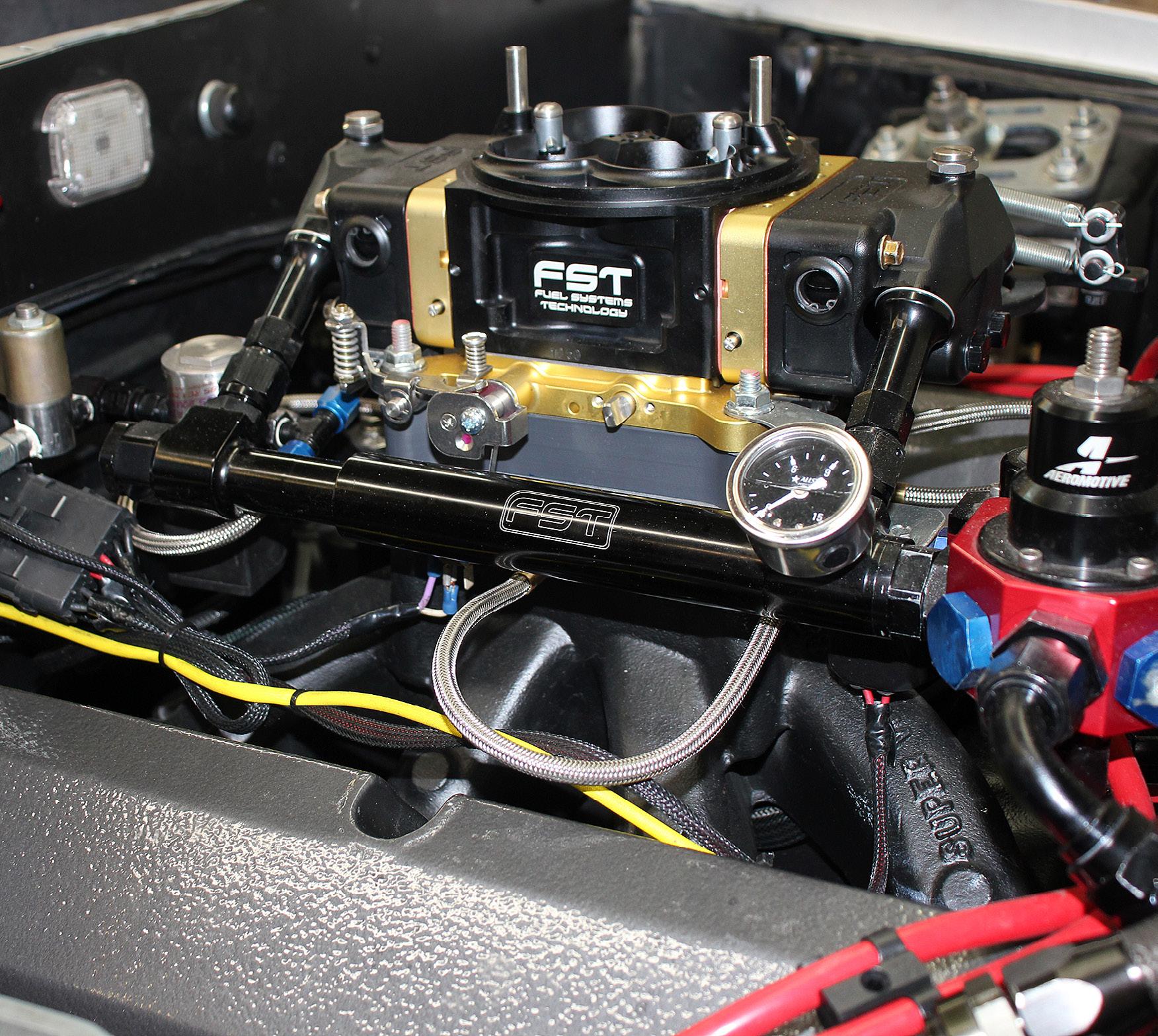
Wired, plumbed and ready to rock! Join us next time as we visit the dyno with Project PCRC and see how much HP we can squeak out of our budget built small block Ford.
up, verify timing and fine tune the timing with your crank trigger position using your timing light, adjust the trigger if required. Next, while the engine is running, ignite your tim-
ing light through the hole in the distributor and align the rotor with the number one post by rotating the distributor. This is called phasing your distributor. Keep in mind, if you ad-

vance or retard your timing from this point, you must re-phase your distributor. Phasing is a must to contain that spark and not let it scatter around the cap.
Since we are running a solid roller camshaft, camshaft break-in procedures do not apply. If you are not using a solid roller, refer to your cam manufacturer for break-in specs.
Next, tune your fuel and throttle blade opening for a consistent idle, and hit a couple thousand rpm. If everything goes well, no leaks (coolant, vacuum, fuel) and temperature is in the motor, shut her down. Next pull the rocker covers and set your valvetrain
again. Start it up and drive the car to seat the rings, if you haven’t already done so on the dyno. Get it up to temp and gradually run it down the road with varying rpm, allowing the rpm to pull the vehicle down in speed. After a couple miles, you should be ready for the dyno.
Stay tuned, next time we meet we’ll have the Pace Car Race Car on the dyno at Misener Motorsports! In the meantime, have a great time enjoying your family and building the cars you love.