(available from spring 2024) (in gradual transition to 3 THORNS and SELF-DRILLING) (available from spring 2024) tip
The complete replacement of the 3 THORNS and SELF-DRILLING tips will take place by 2026 For information on the availability of codes for screws with specific tips, please contact your Sales technician
Srl is not liable in any way for any errors in printing and/or typing. In the event of differences between the contents of the catalogue versions in the various languages, the Italian text is binding and takes precedence with respect to the translations. The latest version of the data sheets available can be found on the Rotho Blaas website.
Pictures are partially completed with accessories not included. Images are for illustration purposes only. The use of third party logos and trademarks in this catalogue is subject to the terms and conditions set out in the general conditions of purchase, unless otherwise agreed with the supplier. Packaged quantities may vary.
This document is private property of Rotho Blaas Srl and may not be copied, reproduced or published, totally or in part, without prior written consent. All violations will be prosecuted according to law. The general purchase and sale conditions of Rotho Blaas Srl are available on the website www.rothoblaas.com
SCREWS AND TIPS TRANSITION
PARTIALLY THREADED - COUNTERSUNK HEAD
PARTIALLY THREADED - FLANGE HEAD
PARTIAL THREAD - PLATE FASTENING
FULLY THREADED - CYLINDRICAL HEAD
FULLY THREADED - COUNTERSUNK HEAD
DOUBLE THREAD - CYLINDRICAL HEAD
MINIMUM DISTANCES FOR SHEAR LOADS | TIMBER
COMPARISON TIPS: SHARP 1 CUT, 3 THORNS and SELF-DRILLING
screws inserted WITHOUT pre-drilled hole
a1 12∙d 10∙d 12∙d a1 5∙d 5∙d 5∙d
a 2 5∙d 5∙d 5∙d a 2 5∙d 5∙d 5 d
a3,t 15∙d 15∙d 15∙d a3,t 10∙d 10∙d 10∙d
a3,c 10∙d 10∙d 10∙d
a4,t 5∙d 5∙d 5∙d
a4,c 5∙d 5∙d 5∙d
screws inserted WITHOUT pre-drilled hole
a3,c 10∙d 10∙d 10∙d
a4,t 10∙d 10∙d 10∙d
a4,c 5∙d 5∙d 5∙d
kg/m3
a1 15∙d 15∙d 15∙d a1 7∙d 5∙d 5∙d a 2 7∙d 7∙d 7∙d a 2 7∙d 5∙d 5∙d
a3,t 20∙d 20∙d 20∙d
a3,c 15∙d 15∙d 15∙d
a4,t 7∙d 7∙d 7∙d
a3,t 15∙d 10∙d 10∙d
a3,c 15∙d 10∙d 10∙d
a4,t 12∙d 10∙d 10∙d
a4,c 7∙d 7∙d 7∙d a4,c 7∙d 5∙d 5∙d
screws inserted WITH pre-drilled hole
a1 5∙d 5∙d 5∙d a1 4∙d 4∙d 4∙d a 2 3∙d 3∙d 3∙d a 2 4∙d 4∙d 4∙d
a3,t 12∙d 12∙d 12∙d
a3,c 7∙d 7∙d 7∙d
a4,t 3∙d 3∙d 3∙d
a3,t 7∙d 7∙d 7∙d
a3,c 7∙d 7∙d 7∙d
a4,t 7∙d 7∙d 7∙d
a4,c 3∙d 3∙d 3∙d a4,c 3∙d 3∙d 3∙d
NOTE: see page 5
LEGEND
(in gradual transition to 3 THORNS and SELF-DRILLING)
(available from spring 2024)
(available from spring 2024) tip
MINIMUM DISTANCES FOR SHEAR LOADS | STEEL-TO-TIMBER
COMPARISON TIPS: SHARP 1 CUT, 3 THORNS and SELF-DRILLING
screws inserted WITHOUT pre-drilled hole
a3,t 15∙d 15∙d 15∙d
a3,c 10∙d 10∙d 10∙d a3,c 10∙d 10∙d 10∙d
a4,t 5∙d 5∙d 5∙d a4,t 10∙d 10∙d 10∙d
a4,c 5∙d 5∙d 5∙d
screws inserted WITHOUT pre-drilled hole
5∙d 5∙d 5∙d
a 2 7 d 0,7 7 d 0,7 7 d 0,7
a3,t 20∙d 20∙d 20∙d
a3,c 15∙d 15∙d 15∙d
a4,t 7∙d 7∙d 7∙d
a4,c 7∙d 7∙d 7∙d
screws inserted WITH pre-drilled hole
a1 5 d 0,7 5 d 0,7 5 d 0,7
a3,t 15∙d 10∙d 10∙d
a3,c 15∙d 10∙d 10∙d
a4,t 12∙d 10∙d 10∙d
7∙d 5∙d 5∙d
a1 4 d 0,7 4 d 0,7 4 d 0,7
a 2 3 d 0,7 3 d 0,7 3 d 0,7 a 2 4 d 0,7 4 d 0,7 4 d 0,7
a3,t 12∙d 12∙d 12∙d
a3,c 7∙d 7∙d 7∙d
a4,t 3∙d 3∙d 3∙d
a4,c 3∙d 3∙d 3∙d
NOTES
• The minimum distances comply with the EN 1995:2014 standard in accordance with ETA-11/0030
• The minimum distances are valid for screws with d1 ≥ 5 mm
• The distances in the table refer to screws inserted in softwood elements (solid timber or glulam) For applications on different materials (e g CLT, LVL), please see ETA-11/0030
• The spacing a1 in the table for screws with 3 THORNS tip in timber-to-timber connections inserted without pre-drilling hole in timber elements with density ρ k ≤ 420 kg/m3 with minimum height and width equal to 10∙d and
a3,t 7∙d 7∙d 7∙d
a3,c 7∙d 7∙d 7∙d
a4,t 7∙d 7∙d 7∙d
a4,c 3∙d 3∙d 3∙d
load-to-grain angle α= 0° equal to 10∙d Alternatively, adopt 12∙d in accordance with EN 1995:2014
• The spacing a1 in the table for screws with SHARP 1 CUT/SELF-DRILLING tip inserted without pre-drilling hole in timber elements with density ρ k ≤ 420 kg/m3 and load-to-grain angle α= 0° was assumed to be 12∙d in accordance with EN 1995:2014
MINIMUM DISTANCES FOR SHEAR LOADS | TIMBER
PARTIAL THREAD SCREWS
screws inserted WITHOUT pre-drilled hole
- SHS AISI 410 - HBS
SHARP 1 CUT
a1 [mm] 10∙d 35 40 45 12∙d 60 72
a 2 [mm] 5∙d 18 20 23 5∙d
[mm]
a3,c [mm] 10∙d 35 40 45 10∙d 50
a4,t [mm] 5∙d 18 20 23 5∙d 25 30 40 50 60
a4,c [mm] 5∙d 18 20 23 5∙d 25 30 40 50 60
screws inserted WITHOUT pre-drilled hole
screws inserted WITH pre-drilled hole
a4,t [mm] 3∙d 11 12 14 3∙d 15 18 24 30 36
a4,c [mm] 3∙d 11 12 14 3∙d 15 18 24 30 36
α = load-to-grain angle
d = d1 = nominal screw diameter
NOTES
• The minimum distances comply with the EN 1995:2014 standard in accordance with ETA-11/0030
• The minimum spacing for all panel-to-timber connections (a1 , a2) can be multiplied by a coefficient of 0,85
• In the case of joints with elements in Douglas fir (Pseudotsuga menziesii), the minimum spacing and distances parallel to the grain must be multiplied by a coefficient of 1 5
• The distances in the table refer to screws with standard SHARP 1 CUT tip
• The distances in the table refer to screws inserted in softwood elements (solid timber or glulam) For applications on different materials (e g CLT, LVL), please see ETA-11/0030
MINIMUM DISTANCES FOR SHEAR LOADS | TIMBER
PARTIAL
THREAD SCREWS
SHS - SHS AISI 410 - HBS - HBS EVO TBS - TBS MAX - TBS EVO - TBS FRAME HBS PLATE - HBS PLATE EVO - KKF d1 [mm] 3,5 4 4,5 5 6
• The minimum distances comply with the EN 1995:2014 standard in accordance with ETA-11/0030
• The minimum spacing for all panel-to-timber connections (a1 , a2) can be multiplied by a coefficient of 0,85
• In the case of joints with elements in Douglas fir (Pseudotsuga menziesii), the minimum spacing and distances parallel to the grain must be multiplied by a coefficient of 1 5
• The distances in the table refer to screws with 3 THORNS tip
• The spacing a1 for screws inserted without pre-drilling hole in timber elements with density ρ k ≤ 420 kg/m3 with minimum height and width equal to 10∙d and load-to-grain angle α= 0° equal to 10∙d Alternatively, adopt 12∙d in accordance with EN 1995:2014
• The distances in the table refer to screws inserted in softwood elements (solid timber or glulam) For applications on different materials (e g CLT, LVL), please see ETA-11/0030
MINIMUM DISTANCES FOR SHEAR LOADS | STEEL-TO-TIMBER
PARTIAL THREAD SCREWS
screws inserted WITHOUT pre-drilled hole
screws inserted WITHOUT pre-drilled hole
HBS - HBS EVO
HBS PLATE - HBS PLATE EVO - KKF SHARP 1 CUT
screws inserted WITH pre-drilled hole
[mm]
α = load-to-grain angle
d = d1 = nominal screw diameter
NOTES
• The minimum distances comply with the EN 1995:2014 standard in accordance with ETA-11/0030
• In the case of joints with elements in Douglas fir (Pseudotsuga menziesii), the minimum spacing and distances parallel to the grain must be multiplied by a coefficient of 1 5
• The distances in the table refer to screws with standard SHARP 1 CUT tip
• The distances in the table refer to screws inserted in softwood elements (solid timber or glulam) For applications on different
LVL), please see ETA-11/0030
MINIMUM DISTANCES FOR SHEAR LOADS | STEEL-TO-TIMBER
PARTIAL THREAD SCREWS
screws inserted WITHOUT pre-drilled hole
[mm]
screws inserted WITHOUT pre-drilled hole
HBS - HBS EVO
HBS PLATE - HBS PLATE EVO - KKF 3 THORNS
screws inserted WITH pre-drilled hole
a1 [mm] 5 d 0,7 12 14 16 5 d 0,7 18 21 28 35
α = load-to-grain angle
d = d1 = nominal screw diameter
NOTES
• The minimum distances comply with the EN 1995:2014 standard in accordance with ETA-11/0030
• In the case of joints with elements in Douglas fir (Pseudotsuga menziesii), the minimum spacing and distances parallel to the grain must be multiplied by a coefficient of 1 5
• The distances in the table refer to screws with 3 THORNS tip
• The distances in the table refer to screws inserted in softwood elements (solid timber or glulam) For applications on different materials (e g CLT, LVL), please see ETA-11/0030
MINIMUM DISTANCES FOR SHEAR LOADS | TIMBER
FULLY THREADED SCREW
screws inserted WITHOUT pre-drilled hole
screws inserted WITHOUT pre-drilled hole
VGZ - VGZ EVO VGS - VGS EVO
SHARP 1 CUT SELF-DRILLING
screws inserted WITH pre-drilled hole
α = load-to-grain angle
d = d1 = nominal screw diameter
NOTES
• The minimum distances comply with the EN 1995:2014 standard in accordance with ETA-11/0030
• The minimum spacing for all panel-to-timber connections (a1 , a2) can be multiplied by a coefficient of 0,85
• In the case of joints with elements in Douglas fir (Pseudotsuga menziesii), the minimum spacing and distances parallel to the grain must be multiplied by a coefficient of 1 5
• The distances in the table refer to screws with standard SHARP 1 CUT/SELF-DRILLING tip
• The distances in the table refer to screws inserted in softwood elements (solid timber or glulam) For applications on different materials (e g CLT, LVL), please see ETA-11/0030
MINIMUM DISTANCES FOR SHEAR LOADS | TIMBER
FULLY THREADED SCREW
screws inserted WITHOUT pre-drilled hole
a 2 [mm]
screws inserted WITHOUT pre-drilled hole
VGZ - VGZ EVO VGS - VGS EVO
screws inserted WITH pre-drilled hole
α = load-to-grain angle
d = d1 = nominal screw diameter
NOTES
• The minimum distances comply with the EN 1995:2014 standard in accordance with ETA-11/0030
• The minimum spacing for all panel-to-timber connections (a1 , a2) can be multiplied by a coefficient of 0,85
• In the case of joints with elements in Douglas fir (Pseudotsuga menziesii), the minimum spacing and distances parallel to the grain must be multiplied by a coefficient of 1 5
• The distances in the table refer to screws with 3 THORNS tip
• The spacing a1 for screws inserted without pre-drilling hole in timber elements with density ρ k ≤ 420 kg/m3 with minimum height and width equal to 10∙d and load-to-grain angle α= 0° equal to 10∙d Alternatively, adopt 12∙d in accordance with EN 1995:2014
• The distances in the table refer to screws inserted in softwood elements (solid timber or glulam) For applications on different materials (e g CLT, LVL), please see ETA-11/0030
MINIMUM DISTANCES FOR AXIAL STRESSES | TIMBER
COMPARISON TIPS: SHARP 1 CUT, 3 THORNS and SELF-DRILLING
screws inserted WITH and WITHOUT pre-drilled hole
SCREWS UNDER TENSION INSERTED WITH AN ANGLE α WITH RESPECT TO THE GRAIN
a1,CG
NOTES
• The minimum distances comply with the EN 1995:2014 standard in accordance with ETA-11/0030
• The minimum distances are independent of the insertion angle of the connector and the angle of the force with respect to the grain
• The axial distance a2 can be reduced down to a2,LIM if for each connector a “joint surface” a1 a2 = 25 d1 is maintained
• For main beam-secondary beam joints with VGZ screws d = 7 mm inclined or crossed, inserted at an angle of 45° to the secondary beam head, with a minimum secondary beam height of 18 d, the minimum distance a1,CG can be assumed equal to 8∙d1 and the minimum distance a2,CG equal to 3∙d1
LEGEND
SCREWS INSERTED WITH α = 90° ANGLE WITH RESPECT TO THE GRAIN standard tip type RBN / RBN2 type RB3T type RBSD tip
(in gradual transition to 3 THORNS and SELF-DRILLING)
CROSSED SCREWS INSERTED WITH AN ANGLE α WITH RESPECT TO THE GRAIN
• The distances in the table refer to screws inserted in softwood elements (solid timber or glulam) For applications on different materials (e g CLT, LVL) please see ETA-11/0030
(available from spring 2024)
(available from spring 2024) tip
MINIMUM DISTANCES FOR AXIAL STRESSES | TIMBER
FULLY THREADED SCREW
VGZ - VGZ EVO VGS - VGS EVO
screws inserted WITH and WITHOUT pre-drilled hole
FULLY THREADED SCREW
VGZ - VGZ EVO VGS - VGS
screws inserted WITH and WITHOUT pre-drilled hole
FULLY THREADED SCREW
screws inserted WITH and WITHOUT pre-drilled hole
NOTES
• The minimum distances comply with the EN 1995:2014 standard in accordance with ETA-11/0030
• The minimum distances are independent of the insertion angle of the connector and the angle of the force with respect to the grain
• The axial distance a2 can be reduced down to a2,LIM if for each connector a “joint surface” a1 a2 = 25 d1 is maintained
• For main beam-secondary beam joints with VGZ screws d = 7 mm inclined or crossed, inserted at an angle of 45° to the secondary beam head, with a minimum secondary beam height of 18 d, the minimum distance a1,CG can be assumed equal to 8∙d1 and the minimum distance a2,CG equal to 3∙d1
SHARP 1 CUT
3 THORNS
SELF-DRILLING
• The distances in the table refer to screws inserted in softwood elements (solid timber or glulam) For applications on different materials (e g CLT, LVL), please see ETA-11/0030
• For the indication of distances and spacing, see the diagrams on page 12
MINIMUM DISTANCES FOR CROSSED CONNECTORS
COMPARISON TIPS: SHARP 1 CUT, 3 THORNS and SELF-DRILLING
screws inserted WITH and WITHOUT pre-drilled hole
plan - 1 PAIR
SECONDARY BEAM WIDTH
3
NOTES
• The minimum distances comply with the EN 1995:2014 standard in accordance with ETA-11/0030
• The minimum distances are independent of the insertion angle of the connector and the angle of the force with respect to the grain
• The axial distance a2 can be reduced down to a2,LIM if for each connector a “joint surface” a1 a2 = 25 d1 is maintained
• For main beam-secondary beam joints with VGZ screws d = 7 mm inclined or crossed, inserted at an angle of 45° to the secondary beam head, with a minimum secondary beam height of 18 d, the minimum distance a2,CG can be assumed equal to 3∙d1
plan - 2 OR MORE PAIRS section standard tip type RBN / RBN2 type RB3T type RBSD tip
• The distances in the table refer to screws inserted in softwood elements (solid timber or glulam) For applications on different materials (e g CLT, LVL), please see ETA-11/0030
MINIMUM DISTANCES FOR CROSSED CONNECTORS
FULLY THREADED SCREW
1
2
VGZ - VGZ EVO VGS - VGS EVO
screws inserted WITH and WITHOUT pre-drilled hole
FULLY THREADED SCREW
VGZ - VGZ EVO VGS - VGS EVO
screws inserted WITH and WITHOUT pre-drilled hole
2
3
FULLY THREADED SCREW
VGZ - VGZ EVO VGS - VGS EVO
screws inserted WITH and WITHOUT pre-drilled hole
d = d1 = nominal screw diameter
NOTES
• The minimum distances comply with the EN 1995:2014 standard in accordance with ETA-11/0030
• The distances in the table refer to screws inserted in softwood elements (solid timber or glulam) For applications on different materials (e g CLT, LVL), please see ETA-11/0030
SHARP 1 CUT
3 THORNS
SELF-DRILLING
For main beam-secondary beam joints with VGZ screws d = 7 mm inclined or crossed, inserted at an angle of 45° to the secondary beam head, with
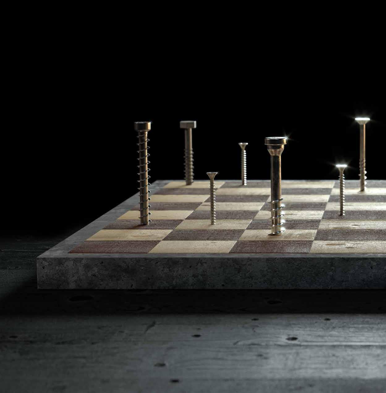
Where some yield, others resist.
Durable connectors, suitable for different materials and all kinds of environments, even the most aggressive Playing a game like this has endless new solutions that we
Set the rules of construction with us, browse the online catalogue!
How much do we know about screws?
Theory, practice, experimental campaigns: putting it all together on screws takes years of lectures, workshops and construction sites We make it available to you in 70 pages that are extra