Information Book


® RotaChock is a registered trademark of Chock Design B.V. © Chock Design B.V. 2022 The contents of this publication are the copyright of the publisher and may not be reproduced (even extracts) without prior written permission having been granted. Every care has been taken to ensure the accuracy of the information in this publication. Still, no liability can be accepted forany loss or damage, whether direct, indirect, or consequential, arising from using the information contained herein. Publication RotaChock® Information Book Edition 10/2022 info@rotachock.com www.rotachock.com FILL THE GAP WITH ROTACHOCK® BASICLINE Page 9 WHAT IS SOFT-FOOT? Page 2 FAST & EASY INSTALLATION OF RESILIENT MOUNTS Page 13 HOW TO INSTALL ROTACHOCK® Page 21 DESIGNER INSTRUCTIONS Page 18 ROTACHOCK® APPLICATIONS & INDUSTRIES Page 25


CONTENTS Understanding Soft-Foot Fill the gap RotaChock® Design Features 5 Production & Certification 7 RotaChock® BasicLine 9 RotaChock® SlimLine 11 RotaChock® Mounting Plate 13 Spherical Spacer 15 Selection & Design Instructions 17 Installation Instructions 21 RotaChock® Applications & Industries 25 Portfolio 27 Frequently Asked Questions 29 About us 35 Contact 36 1 3
UNDERSTANDING SOFT-FOOT

90% OF ALL ROTATING EQUIPMENT IN THE FIELD RUNS OUTSIDE THEIR RECOMMENDED ALIGNMENT TOLERANCES.

70%OF ALL ROTATING EQUIPMENT
FAILURES ARE CAUSED DIRECTLY BY SOFT-FOOT.
We have been highlighting the need for correct alignment in the sector over our entire history of more than 35 years in alignment services. As no one else does, we understand just how hard it can be to achieve an optimal alignment for your rotating equipment. Over the years, we constantly found our customers struggling to keep their alignment within acceptable tolerances. This results in a range of well-known mechanical and quality problems:
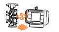
Noise & vibrations
Increased power consumption


Downtime of equipment
These problems with rotating equipment place an enormous cost burden on industries worldwide. When individual critical equipment fails, the entire operation malfunctions and brings production to a full stop. We have found innumerable installations struggling with the problems described above during these long years of experience in alignment services. Making corrections to the shaft alignment makes sense. The question that might appear is why to correct and solve an alignment problem when you can prevent it from happening in the first place and improve the output of your machine?
Our experience is that 70% of all rotating equipment failures are caused directly by a Soft-Foot problem. Realignment of the equipment without solving the Soft-Foot is a temporary solution because the installation will run out of its alignment tolerances again.
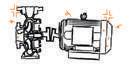
Reduced lifespan of coupling


Accelerated wear and tear
Reduced lifespan of bearings & seals
Your options for permanent and lasting solutions are limited, even if trained mechanics know how to address temporary misalignment problems. But you need an engineering approach to improve the installation and prevent Soft-Foot.
You need to address the root problem.
You need to address the Soft-Foot problem.
Because: why would you start off on the wrong foot?
1 ROTACHOCK ® INFORMATION BOOK
WHAT IS SOFT-FOOT?

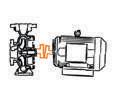
Soft-Foot can be compared to a washing machine that has one leg shorter than the other three. This unevenness and lack of contact with the floor will cause the washing machine to rock. That can also happen with all rotating equipment and may result in machine failure if not corrected.

WHAT’S CAUSING SOFT-FOOT?


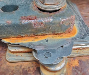
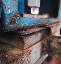
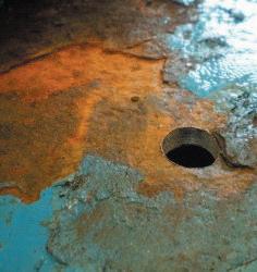
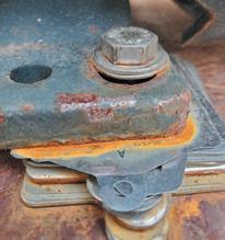
Several factors may cause a Soft-Foot. Maybe the underlying foundation is warped, bent, uneven, or damaged. The same may be true for the machine foot. The gap between the foot and the foundation may already be filled with compressed/bent or otherwise damaged shims. This condition may distort the machine’s frame as the foot is drawn down to the base by the foundation bolt’s tension. In our business, we call this a squishy foot. But also consider environmental factors like dirt and debris, which may have worked their way in-between. A more complex Soft-Foot is caused by forces external to the machine, like stress-induced forces created during any stage of the alignment process.
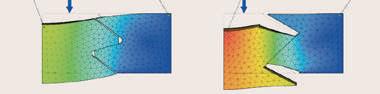
Parallel Soft-Foot; when the machine foot does not have contact with the foundation and creates an in-between gap.


Angular Soft-Foot; when the machine foot makes contact with the foundation on one side only, it bends, resulting in an intermediate angle.

To prevent Soft-Foot, you’ll need something to fill the gap, the space between the foundation and machine foot.

We call this a chock.
 What’s more likely is that you will find a combination of the above causing a Soft-Foot. The most common Soft-Foot situations are:
2
FILL THE GAP
WHAT IS A CHOCK?
A chock is the interface between the foundation and machine foot. All equipment is required by the manufacturer to be affixed to a structural base. There are several options for chocks in the sector, like the steel-fitted blocks, shims, and epoxy resins.
STEEL-FITTED BLOCKS
The use of steel-fitted blocks is a timeconsuming and specialist job. The procedure of measuring, correcting, trial-fitting, and machining needs to be repeated until the steel-fitted block provides a sufficient contact area with the machine foot. Machining these blocks is a considerable cost, even when done in-house.
GAP
an experienced and patient miller is needed
the trial and error procedure can be endless
the cost of milling machinery is considerable relatively easy for parallel Soft-Foot, hard to remedy an angular Soft-Foot


SHIMS
When cutting shims from stock, the sharp burrs may be a safety issue and create errors in stacking up the shims. Pre-cut shims save time, but a stack of them will still hammer in overtime. The angular Soft-Foot will still be there, causing an insufficient support area.
GAP
someone with little experience can do the job
fast when pre-cut cheap in the short term, but stacking is expensive in the long term almost impossible to remedy angular Soft-Foot
EPOXY RESINS

This solution consists of two-component resin and provides a permanent solution. The procedure of preparing, pouring, and waiting for the curing is a timeconsuming process. Whenever the equipment needs to be realigned, the epoxy has to be carved out. Certified personnel must do the material pouring, where there is no room for trial and error.
GAP
certified personnel required
time-consuming installation and curing time
material and cost of certified labour significant risk for installation mishaps
These methods have two primary goals: to create a flat mounting surface for the equipment and to transfer the reactive force from the machine feet to the foundation. Unfortunately, with the above chock methods, a high risk of a Soft-Foot remains. Our years of experience in alignment services taught us that down the line; all applications need realignment at some point. A lot can happen during transport, installation, or the application lifetime. In these situations, time is of the essence, money is at stake, and the equipment needs to be up and running again as soon as possible.
You need an adjustable solution.
3 ROTACHOCK ® INFORMATION BOOK
DEVELOPMENT OF ROTACHOCK®
All known techniques have two basic goals: creating a flat mounting surface and transferring forces from the machine feet to the foundation. However, our third goal was to design a solution to prevent Soft-Foot, which can still be adjusted later. That’s why we have blended technologies to evolve mechanical chocking, and we proudly present a technically superior gap filler to end Soft-Foot:
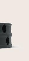
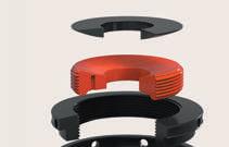
The RotaChock® is an adjustable, self-leveling, and reusable chock for mounting rotating equipment. The RotaChock® is a blend of engineering and years of field experience that has resulted in a robust, stiff, and elegant gap-filler to end machinery Soft-Foot. RotaChock® achieves the primary chock goals, plus our additional adjustability feature, which is unmatched in the industry.
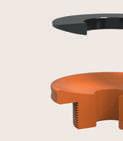
The threaded part enables adjustability of the chock which solves parallel Soft-Foot.
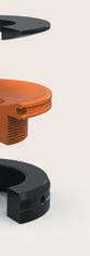
ROTACHOCK® CONSISTS OF 3 PARTS:


Top ring with a convex surface, resting in the concave middle ring.
Middle ring with a male thread and a concave cavity on top.
Bottom ring with a female thread.
The spherical top accommodates for angular differences up to 4° and solves angular Soft-Foot.
BENEFITS OF ROTACHOCK®
Primarily, we consider RotaChock® to be the best lifecycle solution for rotating equipment for the following reasons:
› RotaChock® eliminates Soft-Foot


› RotaChock® is adjustable, making alignment and realignment possible whenever needed
› RotaChock® saves time and money compared with other chocking options


The RotaChock® can be supplied in a variety of configurations to suit your application. In this information book, we keynote all available options and the applications that they suit best. All technical details, installation notes, and engineering tips & tricks will be explained in the following pages.

4
ROTACHOCK® DESIGN FEATURES


DESIGN PHILOSOPHY
The weakest link in any RotaChock® application is the foundation bolt that ties the machine foot to the foundation. As a failsafe, we used an effective design principle: geometry. The thread diameter of RotaChock® is at least two times the allowable foundation bolt diameter. As a result, the RotaChock® thread can’t be damaged by bolt tension.
THREAD DESIGN

The rotating equipment’s alignment tolerance is within a few hundredths of a millimeter (0,02–0,05 mm). It’s critical to have a perfect thread design to minimize trial and error during alignment.
RotaChock® uses a special thread type, called buttress thread. Unlike common thread types used in mechanical engineering, metric (M) and unified national (UNC, UNF), buttress thread has an asymmetric design comprising a 7° top angle and a 45° supporting flank.
Buttress thread Metric thread
Female thread Male thread Female thread Male thread
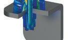
Because of this thread design, RotaChock® has a higher mechanical stiffness and a higher load-bearing capacity than a standard Metric thread of similar diameter and pitch using a 2x30° angle design. The buttress thread’s self-locking characteristics ensure no need for a mechanical locking device to prevent the RotaChock® from rotating under load.
Buttress thread design has standard terms and definitions for tolerance, following ISO 965-1. Per ISO-standard, clearance is created between interlocking threads. When the nut and bolt are manufactured, this is referred to as deviation.
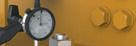
In our RotaChock® design philosophy, this was not enough. That’s why we have created a perfect matching clearance which we can constantly check in-house. We have developed special measurement techniques and calipers to check this during production. This method ensures a minimum deviation between threads and a final thread clearance with less than a 0,05 mm / 0,002” thread setting after tightening the foundation bolts.
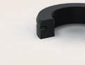
TOOL GROOVE DESIGN
Adjusting the RotaChock® is a simple task that can be accomplished using simple tools. The unique and practical tool groove design makes this possible. In some installations, RotaChock® is not visible because it’s in a tricky position. You can insert your tool in the groove and follow it to the next adjustment hole in these situations.
Buttress and metric thread displacement under load.
5 ROTACHOCK ® INFORMATION BOOK
Each type of RotaChock® has a dimension chart, and there are multiple sizes of RotaChock® available per type:
RC2-C 100 51 30
RC3-C 150 76 45
RC4-C 200 102 65
RC4.5-C 300 114 73 31
10/16 18 23 1.6 0.4
16/20 24 23 1.6 1.1
53 20/27 30 28 2.1 2.2
53 60 24/30 33 31 2.1 3.1
RC5-C 400 127 80 37 50 58 67 30/36 39 32 2.1 4.3
RC6-C 600 152 95 41 55 65 74 36/39 45 37 2.1 6.8
RC7-C 900 178 120 46 60 68 76 42/45 48 45 3.2 10.1
RC8-C 1200 203 135 54 70 81 91 48/52 56 50 3.2 15.3
RC9-C 1600 229 160 66 75 84 93 56/64 68 58 3.2 20.7
RC10-C 2000 254 180 74 80 89 98 64/72 76 63 4.2 27.3
Type
Type and size of RotaChock®. The outside diameter in inches is the same as the RC size. For example, RC2 is 2 inches in outside diameter.
Rated Load
The rated load that can be exerted on the RotaChock® and is approved by classification authorities.
Outside Ø
The largest outside diameter of the RotaChock®.
Thread Ø
The thread diameter of RotaChock® that should be fully underneath the machine foot.
Inside Ø
The diameter of the middle hole of the RotaChock® through which the foundation bolt will pass.
Minimum height
The height of the RotaChock® when it is fully screwed in.
Design height
The height that puts the RotaChock® exactly in the middle of its adjustable range.
Maximum height
Exceeding this height leaves too little engaged thread to carry the load safely.
Standard bolt size
The preferred foundation bolt diameter to be used in combination with RotaChock®.
Optional bolt size
Should you want to use a larger foundation bolt diameter than the hole in the RotaChock® permits, then it is also possible to enlarge the hole in the RotaChock®. Please see FAQ #7 on page 30 for further instructions on enlarging bolt holes.
Reduced minimum height
Should the RotaChock® be too high for the available space, then it’s possible to reduce the height of the RotaChock® on a lathe. Remember that for every mm you take off, you will also lose 1 mm of adjustment. Please see FAQ #6 on page 30 for further instructions on reducing height.
Pitch
The RotaChock® height increment after one complete revolution.
Weight
The weight of the RotaChock®
ROTACHOCK® DIMENSION CHART RotaChock ® BasicLine Rated load Outside ø Thread ø Inside ø Min. height Design height Max. height Standard bolt size Optional bolt size Reduced min. height Pitch Weight kN mm mm mm mm mm mm M M mm mm kg
17 30 34 38
21 35 40 45
28 40 47
45
6
PRODUCTION & CERTIFICATION
MATERIALS
The technical approach for developing RotaChock® was to create the highest load rating viable while using the lowest yield strength material required by the industry, 316 Stainless Steel, as per API guidance. The standard approach for RotaChock® uses carbon steel and alloy steel chocks, which have an even more significant margin of safety over the yield strength stated below. The standard and stocked range of RotaChock® are:
› RCx-C BasicLine Carbon Steel (DIN 1.0507
RCx-SS BasicLine Stainless Steel
RCx-AS BasicLine Alloy Steel
RCx-SL SlimLine Carbon Steel
threaded
of Alloy steel
MECHANICAL PROPERTIES
Young's modulus
Tensile strength
strength
Elongation
Fatigue
-
1.0507
standard go to design
maximum protection against rust
handling extreme machinery
repair and retrofitting market
-
ANTI-CORROSION ENHANCED
Another RotaChock® innovation is the research and implementation of a process to inhibit rusting in normal steel chocks. Stainless Steel 316L is an excellent and required material for highly corrosive applications, but it comes at a price. Therefore, we selected the molecular diffusion process for carbon steel and alloy steel chocks to offer more cost-effective corrosion protection.
This process enhances wear properties and significantly improves corrosion resistance. The process is a combination of various thermochemical process steps, including gas nitrocarburizing and oxidizing. Wear and corrosion-resistant layers are created, which show a black color and have negligible dimensional distortion.
We call the process Anti-Corrosion Enhanced – ACE! This process features the following characteristics:
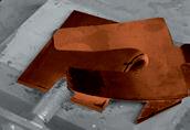
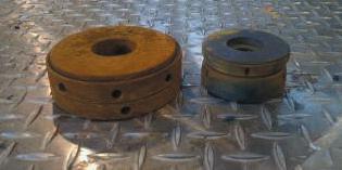
Comparisons through salt-spray testing show that stainless 316L marks at 480 hours and carbon steel that is
Anti-Corrosion Enhanced marks at 320 hours, whereas untreated carbon steel marks within 90 minutes.
An untreated and ACE-treated RotaChock® after salt spray test
Quantity Unit DIN1.0507/S355 DIN1.4404/AISI 316L DIN1.7225/42CrMo4
MPA 210.000 200.000 210.000
MPA 520
620 580 - 650 1000 - 1200 Yield
MPA 360 280 550 - 800
% 22 45 11
MPa 270 Impact strength J/cm 0.7
0.9 140 - 150
- S355) Anti-Corrosion Enhanced the
›
(DIN 1.4404 - 316L) for
›
(DIN 1.7225 - 42CrMo4) Anti-Corrosion Enhanced for
forces ›
&
(DIN
- S355) Anti-Corrosion Enhanced for
parts
(DIN 1.7225 - 42CrMo4) 1 High resistance to wear 2 Excellent scuffing and seizure resistance 3 Fatigue properties improved by up to 120% 4 Considerably improved corrosion resistance If there might be a requirement for other materials or treatments for specific applications, these can be supplied upon request. 5 Good surface finish 6 Negligible shape distortion 7 Predictable growth characteristics 8 Alloy substitution – Plain carbon steels replacing alloy steel 7 ROTACHOCK ® INFORMATION BOOK
PRODUCTION & QUALITY CONTROL
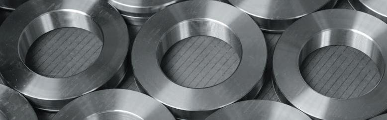
All RotaChock® are manufactured in ISO-certified machine shops. Modern CNC equipment and state-of-the-art measurement tools are used to guarantee a constant and high-quality level.

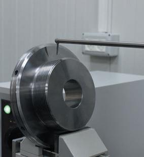
Production is assessed annually for approval by certification institutes, backed up by audits from RotaChock® users, who are industry leaders. With the quality systems in place, all markets can be served, from navy to nuclear.

The production process is constantly monitored using measurement techniques and calipers that were developed in-house. The final thread clearance checks are performed with a surface roughness/contour measuring system. This method ensures a minimum deviation between threads. The final clearance of less than 0,05 mm / 0,002” minimizes thread setting after tightening the foundation bolts.

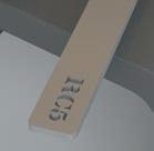
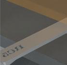
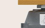
PRODUCT TRACEABILITY

RotaChock® is produced in batches, where every batch has a unique code engraved on the steel element and labeled on the packaging. The batch codes link to our production database containing material certificates and measurement reports which are available on request. These batch codes provide the following information:
RC4-C-220403

RC RotaChock®
RotaChock® size.
dimension chart,
RC4
C Material
Carbon steel


Stainless steel
Alloy steel
Year of production
Product type
BasicLine


SlimLine
RotaChock® size

dimension chart, 5 = RC5

Batch number of that year
TYPE APPROVALS


RotaChock® has been approved by various classification authorities, enabling the use of RotaChock® underneath propulsion machinery and auxiliary installations onboard ships without having to go through a lengthy plan approval application. RotaChock® have been “Type Approved” by all major classification societies, like:


4
Check
4 =
› C
› SS
› AS
22
0
› 0
› 1
4
See
03
8
ROTACHOCK® BASICLINE


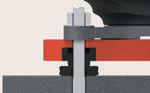
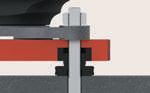
This type is the primary solution for new designs and applications being built. When the gap height is still on the drawing board, just put in the RotaChock® BasicLine. The foundation bolt runs through the center hole of the RotaChock®, clamping the machine foot, the RotaChock®, and the top plate of the foundation together securely. When your equipment’s realignment is required, just loosen the foundation bolts and adjust the RotaChock® BasicLine to meet your target alignment. This adjustability feature is unmatched in the industry and creates vital time benefits compared to other chocking solutions.
OPTIMUM CONTACT SURFACE
The RotaChock® has a spherical top part that ensures the best possible contact surface, even if the foundation and the machine foot are not parallel. The RotaChock® is also heightadjustable. The combination of these two features prevents Soft-Foot.
ANY DESIRED TORQUE
The RotaChock® behaves like a solid steel chock and allows the foundation bolt to be tensioned to any required torque. Epoxy resin chocks, in contrast, have a maximum load of 5 N/ mm2. This relatively low torque often results in almost loose foundation bolts.

SPEED
RotaChock® is installed quickly. A machine set up on a RotaChock® can generally be realigned and secured within an hour. In comparison: using epoxy resin can take days due to the long curing time. Measuring, production, and fitting of steel fitted blocks take even longer, and labor costs make that reasonably expensive.
HIGH LOADS
RotaChock® competitive edge is its large footprint: the surface area of the bottom ring in contact with the foundation is larger, so the pressure exerted on that surface is lower. RotaChock® also uses a buttress thread design. These features allow RotaChock® to carry greater loads.
9 ROTACHOCK ® INFORMATION BOOK
Spherical top ring for angular difference up to
between the machine foot and the foundation.
Tool groove and holes to aid installation with a wide range of tools.
Buttress thread design for maximum strength and stiffness.
The footprint is large and reduces surface pressure.
ROTACHOCK® BASICLINE DIMENSION CHART
Standard ACE finish: AntiCorrosion Enhanced for costeffective corrosion protection.
covering the full range of
The RotaChock® BasicLine
to
RC2-C
RC3-C
RC4-C
RC4.5-C
RC5-C
RC6-C
ROTACHOCK® BASICLINE CONFIGURATIONS

RotaChock® BasicLine can be supplied in a variety of materials. We advise the use of our standard RotaChock® BasicLine that is manufactured from S355 (DIN1.0570) and Anti-Corrosion Enhanced for regular applications. For maximum protection against corrosion in extreme environments, RotaChock® BasicLine can be supplied in stainless steel (316L). For maximum strength when handling extreme forces, RotaChock® BasicLine can be supplied in alloy steel (i.e.,
Please check page 7 for more information on the available
surface
Read
selection
instructions
check the
selection tool at www.rotachock.com
Read
installation
download all Type Approvals and RotaChock®
You
drawings in both
online at
You can find the frequently asked questions regarding RotaChock® BasicLine on page 29 or online at www.rotachock.com
with
selection of RotaChock® BasicLine.

34CrNiMo6).
materials and
treatments.
consists of 10 different sizes ranging from 51 mm to 254 mm outside diameter and
M12 up
M72 foundation bolts. The rated load of RotaChock® increases with the outer diameter.
4°
ROTACHOCK® BASICLINE DESIGN HAS THE FOLLOWING DESIGN FEATURES RotaChock ® BasicLine Rated load Outside ø Thread ø Inside ø Min. height Design height Max. height Standard bolt size Optional bolt size Reduced min. height Pitch Weight kN mm mm mm mm mm mm M M mm mm kg
100 51 30 17 30 34 38 10/16 18 23 1.6 0.4
150 76 45 21 35 40 45 16/20 24 23 1.6 1.1
200 102 65 28 40 47 53 20/27 30 28 2.1 2.2
300 114 73 31 45 53 60 24/30 33 31 2.1 3.1
400 127 80 37 50 58 67 30/36 39 32 2.1 4.3
600 152 95 41 55 65 74 36/39 45 37 2.1 6.8 RC7-C 900 178 120 46 60 68 76 42/45 48 45 3.2 10.1 RC8-C 1200 203 135 54 70 81 91 48/52 56 50 3.2 15.3 RC9-C 1600 229 160 66 75 84 93 56/64 68 58 3.2 20.7 RC10-C 2000 254 180 74 80 89 98 64/72 76 63 4.2 27.3
the
and design
on page 17 or
RotaChock®
to assist
your
the
instructions on page 21 or check the installation videos at www.rotachock.com to assist with your installation of RotaChock® BasicLine.
can
BasicLine
2D & 3D
www.rotachock.com
10
ROTACHOCK® SLIMLINE

If the RotaChock® BasicLine doesn’t fit the available space between the machine foot and the foundation, the RotaChock® SlimLine probably will.

With an overall height starting at only 20 mm, the RotaChock® SlimLine will suit most of the retrofit applications while still offering an adjustment range of 10 mm.

RotaChock® SlimLine is designed for retrofitting epoxy-grouted installations. Whenever the equipment needs to be realigned, this epoxy has to be carved out again. The design heights of epoxy resin chocks are in the range of 20 to 40 mm. That’s why the SlimLine range has been designed around these same heights. Now you can carve out the epoxy and replace it directly with RotaChock® SlimLine.
This design is not only intended for the retrofit and repair market: RotaChock® SlimLine can be used in all applications and every design. When there is insufficient space to fit the BasicLine, the SlimLine can do the same job but at a minimum height.
11 ROTACHOCK ® INFORMATION BOOK
footprint is large and reduces surface
ROTACHOCK® SLIMLINE DIMENSION CHART
groove and holes
installation with
range of tools.
Standard ACE finish: Anti-Corrosion Enhanced for cost-effective corrosion protection.
ROTACHOCK® SLIMLINE CONFIGURATIONS

RotaChock® SlimLine can be supplied in a variety of materials. For regular applications, we advise the use of our standard RotaChock® SlimLine. This one is manufactured from S355 (DIN1.0570), with the threaded parts made of alloy steel (42CrMo4), and is Anti-Corrosion Enhanced for cost-effective corrosion protection. For maximum protection against corrosion in extreme environments, RotaChock® SlimLine can be supplied in stainless steel (316L). For maximum strength when handling extreme forces, RotaChock® SlimLine can be supplied in alloy steel (i.e.34CrNiMo6). Please check page 7 for more information on the available materials and surface treatments.
Read the selection and design instructions on page 17 or check the RotaChock® selection tool at www.rotachock.com to assist with your selection of RotaChock® SlimLine.
Read the installation instructions on page 21 or check the installation videos at www.rotachock.com to assist with your installation of RotaChock® SlimLine.
You can download all Type Approvals and RotaChock® SlimLine drawings in both 2D & 3D online at www.rotachock.com
You can find the frequently asked questions regarding RotaChock® SlimLine on page 29 or online at www.rotachock.com
ROTACHOCK® SLIMLINE DESIGN HAS THE FOLLOWING DESIGN FEATURES RotaChock ® SlmLine Rated load Outside ø Thread ø Inside ø Min. height Design height Max. height Standard bolt size Pitch Weight kN mm mm mm mm mm mm M mm kg RC3-SL 250 76 55 28 20 25 30 16/27 1.6 0.6 RC4-SL 300 102 73 31 20 25 30 20/30 2.1 1.1 RC5-SL 600 127 95 41 25 30 35 30/39 2.1 2.0 RC6-SL 900 152 115 41 30 35 40 36/39 2.1 3.2 RC7-SL 1200 178 135 54 30 35 40 39/52 2.1 4.9
The RotaChock® SlimLine consists of 5 different-sized elements ranging from 76 mm to 178 mm. in outside diameter and covering the full range of M16 up to M52-sized foundation bolts. The rated load of RotaChock® increases with the outer diameter. Spherical top ring for angular difference up to 2° between the machine foot and the foundation. Tool
to aid
a wide
Buttress thread design for maximum strength and stiffness. The
pressure.
12
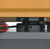
ROTACHOCK® MOUNTING PLATE


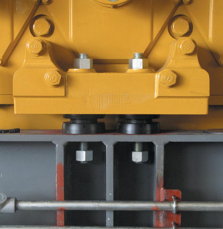
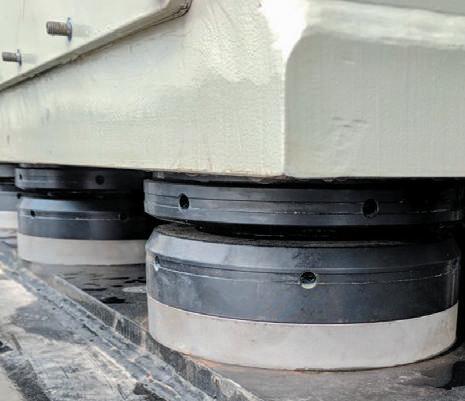
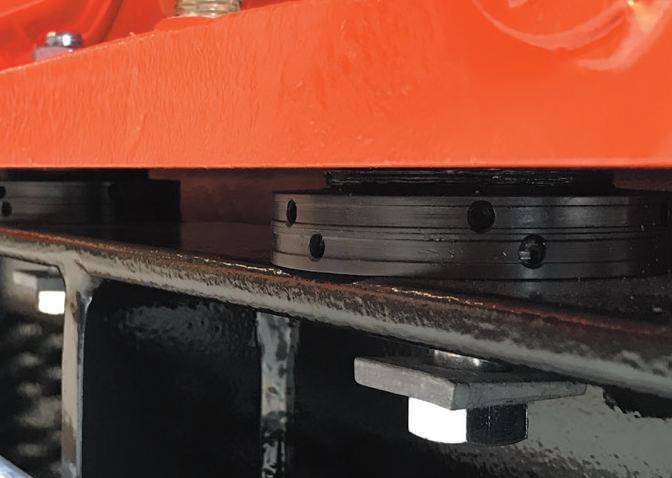
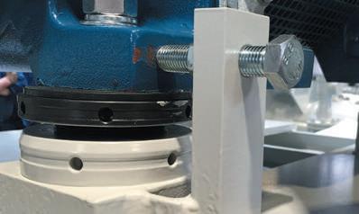
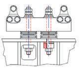
The installation of resilient mounts can be challenging. The rubber mount’s base plate must be aligned perfectly parallel to the machine foot to ensure optimal vibration damping. The traditional way to set up the resilient mount is to use the four adjustment bolts to eliminate any angle between the cap and the base plate and then to fill the gap between the base plate of the mount and the foundation with two-component epoxy resin or a tailor-made steel-fitted block.


The RotaChock® philosophy of eliminating Soft-Foot can also be used for quick and easy installation of these resilient mounts. That’s why the RotaChock® Mounting Plate was developed in close cooperation with leading developers of resilient mounts. We integrated four RotaChock® in the corners of a stiff Mounting Plate.
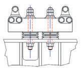
The RotaChock® Mounting Plate offers an economical alternative to epoxy resin or tailor-made steel-fitted blocks. The adjustment bolts in the RotaChock® Mounting Plate are used to eliminate any angle between the mount’s foundation and base plate. Now the four RotaChock® at the corners are adjusted to fill the gap. The base plate, RotaChock® Mounting Plate, and machine foundation are then tightened together securely with four foundation bolts.
The mounting system can be readjusted at any time if required. Just loosen the foundation bolts and adjust the RotaChock® Mounting Plate to meet your target alignment. The time needed to finish a typical resiliently mounted machine can be cut back from several days to only a few hours.
13 ROTACHOCK ® INFORMATION BOOK
Spherical top ring for angular difference

to
foot

groove and holes
aid installation with a wide range of


ADVANTAGES OF ROTACHOCK® MOUNTING PLATE


The benefits of the RotaChock® Mounting Plate in comparison with other chocking solutions like epoxy resin and steel-fitted blocks are:

› The main benefit of RotaChock® is the adjustability feature. Corrections and adjustments are always possible. When using epoxy resins or steel-fitted blocks, you need to cut out the epoxy resin or remove the steel block and redo the entire lengthy and costly process.
› Speed: RotaChock® is installed quickly. A machine set up on a RotaChock® can generally be realigned and secured within hours. When using epoxy resins, it takes at least three days for the machinery to function again due to the resin’s relatively long curing time of 36-48 hours. When using steelfitted blocks, measuring the gap, milling the steel chock, and the welding process will take several days.
› RotaChock® is user-friendly; no special skills are required for installation. Unlike epoxy resins, no certified people are needed for the installation job to retain a warranty. For the local procedure of measuring, correcting, blue-fitting, and machining steel-fitted blocks, experienced and patient millers are required.
ROTACHOCK® MOUNTING PLATE DIMENSION CHART


› Steel-fitted blocks need to be measured separately and machined for each resilient mount. The RotaChock® solution is a standard design with an adjustability range - one fit per resilient mount that can be height adjusted.
› No heating is required when using RotaChock®; heat could influence the alignment target negatively. Epoxy resins need to be heated to cure, and steel-fitted blocks need to be welded to the foundation.
› RotaChock® behaves like a solid steel chock, and RotaChock® allows the foundation bolt to be tensioned to any required torque. In contrast, epoxy resins have a maximum load of 5 N/mm2. This relatively low torque often results in almost loose foundation bolts.
› RotaChock® is eco-friendly; epoxy resins contain mixed and aggressive chemical components which are dangerous for the users.
Selection of RotaChock® Mounting Plate is easy: just check your resilient mount bolt pattern and match this with the table below.
The standard RotaChock® Mounting Plate is manufactured from S355 (DIN1.0570) and is Anti-Corrosion Enhanced for cost-effective corrosion protection. Please check page 7 for more information on the available materials and surface treatments.


RotaChock ® Mounting Plate Min. height Design height Max. height Bolt size Bolt pattern Compatible with mm mm mm M mm MP-RC2BT 40 43 48 16 190X140 T35/T60/RD3'S MP-RC3BT 45 49 58 20 205X150 T50/T90/RD2'S MP-RC4BT 50 55 63 27 310X240 T75/T130/T140/T170/RD1'S
up
4° between the machine
and the foundation. Tool
to
tools.
Buttress thread design for maximum
strength
and
stiffness.
Standard ACE finish: AntiCorrosion Enhanced for cost-effective
corrosion protection.
ROTACHOCK® MOUNTING PLATE DESIGN HAS THE FOLLOWING DESIGN FEATURES: 14
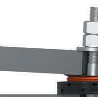
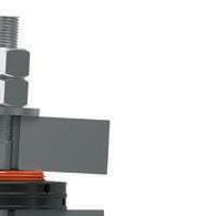
SPHERICAL SPACER


The purpose of chocking is to create a perfect coplanar mounting surface for the machine. RotaChock® fills the gap between the machine foot and its foundation and solves parallel and angular misalignment. But this doesn’t mean that a hardware misalignment can’t still occur. Whether using RotaChock®, epoxy resins, or steel-fitted blocks, inadequate bolt stretch through hardware misalignment means a loose foundation bolt. In some cases, there is a hardware misalignment, as shown below.


THE PROBLEM
In shipbuilding, classification authorities have required the underside of foundations to be spotfaced or counterbored so that the surfaces are parallel. In other industries, extra-long studs are specified. These long studs mitigate stress build-up but do not benefit the lifecycle. Why machine the foundation or mitigate the problem when you could solve it?
THE SOLUTION
The Spherical Spacers accomplish two functions: creating hardware planes and bolt elongation. This solution comprises two parts with a smooth concave and convex curvature, resulting in an angular offset angle of 4°, which creates the hardware plane. The standard heights elongate the bolt and create extra clamping length.
Most market-available spherical washers have a spherical x conical cross-section configuration. Due to the line contact between spherical and conical contours, these washers could prove problematic. I.eg. when your application is subject to high vibration loading, seismic shock, or marine application loading.

SPHERICAL SPACER DIMENSION CHART
Selecting a Spherical Spacer is easy; they are designed specifically for the foundation bolt used. Just check the bolt you are using and match this with the chart. The standard Spherical Spacers are manufactured from 42CrMo4 (DIN1.7225) and are Anti-Corrosion Enhanced for cost-effective corrosion protection. Please check page 7 for more information on the available materials and surface treatments.

Point
Spherical Spacer Outside ø Inside ø Height range Standard bolt size Reduced min. height Weight mm mm mm M mm kg SS16/18 37 19 50 16/18 20 0.2 SS20/22 46 23 50 20/22 20 0.4 SS24/27 56 28 60 24/27 28 0.7 SS30/33 67 34 60 30/33 28 1.0 SS36/39 80 40 70 36/39 34 1.7 SS42/45 93 46 70 42/45 34 2.3 Point contact Matched surfaces DIN 6319 with spherical x conical cross-section
contact Matched Spherical Spacer with smooth concave and convex curvature
15 ROTACHOCK ® INFORMATION BOOK
SPECIFIC DESIGN SOLUTIONS


As the market and technology leader, we have been developing, producing, and marketing innovative chocking solutions for all kinds of rotating equipment and chocking scenarios. If there isn’t a standard solution, our engineering team can provide a tailor-made RotaChock® solution for your application.
In the below overview, you can find RotaChock® solutions which are developed and being used in niche markets or unique situations:


ROTACHOCK® HEXLINE


Even for the smallest rotating equipment, an easy and fast alignment is possible with RotaChock® HexLine. These small-sized Hexagon RotaChock® are ideal for small equipment like pump sets where accurate alignment is still crucial. This solution has the same principle as all RotaChock®: an adjustable threaded center for parallel differences and a spherical top to overcome angular differences. Thanks to the hexagonal design, adjustment is performed with a simple wrench/spanner.

ROTACHOCK® TALLLINE


Shaft center line heights between the driver and the driven equipment usually differ. Most often, height pedestals are affixed to the skid to accommodate these differences. This solution is costly because additional craftsmanship is essential to fit up the steelwork. Our solution is a RotaChock® supplied with a taller height to suit your application. However, there are some considerations for using Tall Line configurations, i.e., when thrust or shear forces are involved.

ROTACHOCK® TALLER TOP RINGS
Some applications have configurations with only a slight difference between shaft center-line heights. Many times, the adjustment range of RotaChock® is sufficient to accommodate the differences. But if 5 to 25 mm in additional height is needed, then a taller top ring is more economical than other solutions. Stocking sets of Taller Top Rings can save you time during assembly when you find yourself slightly out of your designed gap height.


ROTACHOCK® ADJUSTMENT TOOLS
RotaChock® grooves and holes aid installation, and various types of tools can be used. Nevertheless, some technicians enjoy the feel of a spanner or wrench. A range of adjusting tools has been designed and are available for each RotaChock® size.
16
SELECTION & DESIGN INSTRUCTIONS
SELECT YOUR ROTACHOCK® BY BOLT SIZE AND GAP HEIGHT:
Select a RotaChock® based on the foundation bolt diameter size and available gap height:


Scan QR for selection tool.


› Match the foundation bolt diameter with the standard bolt diameter from the RotaChock® dimension chart. For example, M36 = RC5 or RC6
› Match your gap height with the design height from the RotaChock® dimension chart. For example, M36 and gap height of 28 mm, use RC5-SlimLine. M36 and gap height of 56 mm, use RC5-BasicLine

can
If the gap height is still on the drawing board, use the design heights of the RotaChock® BasicLine. This method is a quick and easy way of selecting the correct RotaChock® size. At www.rotachock.com, you can find the RotaChock® Selection Tool that can assist with your selection.

SELECTION BASED ON LOAD CALCULATION BY ROTACHOCK® DISTRIBUTOR
If you’re looking for a more detailed selection, please complete the RotaChock® Data Form and submit it to your local RotaChock® distributor. Given the details of your equipment, your local distributor can run the sizing calculation free of charge. Download this data form at www.rotachock.com Page 19 includes an in-depth explanation of the formulas we use for this calculation method.
PLAN APPROVALS OR COMPLEX INSTALLATIONS
Plan approvals are required for propulsion and auxiliary equipment in marine applications, which require classification approval. For these applications, a RotaChock® engineering proposal can be provided, including all calculations and a sketch of the chocking arrangement, to obtain plan approval from the appropriate classification authority.
When your machinery and the foundations are subject to more complex forces, our team can perform an in-depth structural analysis, including computer modeling and finite element analysis.
In any case, you can call on the services of our engineering team by submitting your completed data form (which can be downloaded from www.rotachock.com) with 2D/3D drawing files to engineering@rotachock.com
Check foundation bolt diameter Check gap height Select RotaChock® size ROTACHOCK® CAN BE SELECTED VIA THREE METHODS 1. 2. 3.
17 ROTACHOCK ® INFORMATION BOOK
60% - 70% of proof load
tightening torque.
limit
point
zone
stretch
zone
ΔL
FRICTIONAL LOSSES
10% converted to preload
50% at nut face
40% in theads
HOW TO SELECT BOLT SIZE
Each industry has its specifications for foundation bolting, and each manufacturer has its bolting preferences. RotaChock® is designed around the foundation bolt, so simply follow the designer’s initial bolting instructions. Any size, grade, and style of bolting can be used in combination with RotaChock®
In general, we advise following the manufacturer’s design instructions. Where an M24 foundation bolt is specified on the drawing, use this. If only the hole diameter is specified, select the appropriate foundation bolt from the table on page 20 following ISO 273.
If the bolt grade is not specified, we recommend using 8.8 graded bolts (yield strength 640 N/mm2) for RotaChock® applications. The foundation bolt must be tightened within the elastic range of the bolt material. When using 8.8-grade bolts (yield strength 640 N/mm2), we recommend a tension of 60% - 70% of the bolt material’s yield strength.
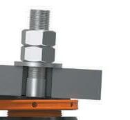
BOLT STRETCH
The left illustration shows what happens when torque is applied to a dry bolt. Only about 10% of the effort put into the spanner or wrench is converted to bolt preload. The resulting stretch is the only thing keeping the bolted connection tight.
As a direct result of the torque applied to the foundation bolt or nut during installation, this bolt stretch is critical for the machine’s lifecycle performance. The bolt stretch needs to be sufficient to accommodate a stretch loss due to flattening the nut, bolt head, foundation, and washers’ surface roughness.
Frictional Losses (dry steel bolt)
machine foot foundation
If the bolt stretch is insufficient, the fastener may not stay tight, and the connection may loosen and fail. We, therefore, recommend a minimum bolt stretch of 0,20 mm
CLAMPING LENGTH
If there is insufficient bolt elongation, the clamping length may be increased. To do so, we recommend our Spherical Spacer, which also creates a perfect mounting plane for the bolt head or nut. More information on the Spherical Spacer can be found on page 15.
The clamping length is the total distance between the bolt head and nut. In a typical RotaChock® mounting setup, this equals the sum of:
› top spacer height
machine foot thickness
RotaChock® design height
foundation thickness
bottom spacer height
8.8-grade bolts (yield strength 640 N/mm2) with tension in the range of 60% - 70% of the bolt material’s yield strength require a minimum clamping length of 95 mm to result in a minimum bolt stretch of 0,20 mm
›
›
›
›
recommended
Necking Plastic
Elastic
Tension load Elastic
Yield
Tensile strength Total failure F Elongation
18
The RotaChock® calculation tool has been developed in cooperation with OEMs and classification authorities. When provided with your application details, your local distributor can run the calculation for a sizing recommendation. Below you can find an explanation of the formulas used.
The following forces act on the RotaChock® during operation of the machine:
1 Static load (weight of the machine resting on the RotaChock®)
2 Torque reaction force
3 Thrust force (e.g. propeller thrust)
4 Bolt force
1
STATIC LOAD
FWEIGHT Force as a result of the machine’s weight acting within Earth’s gravity [N]
M Mass of the machine [kg.]
G Gravitation field strength = 9,81 m.s2
N Total number of RotaChock® installed
The following formulas are being used in our sizing recommendations:
5 In marine applications where classification authority rules apply: a C-factor is mandatory per class guidance. This C-factor is a combined and rounded value based on lubrication, friction, and thread design assumptions. When calculating under class rules, the use of this C-factor is mandatory.
6 In applications where classification rules are not applicable, bolt torque is calculated per ISO 16047. The coefficient of friction is defined when selecting specific bolt lubrication.
7 Stretch as a direct result of the torque applied to the bolt or nut during installation.
4
BOLT LOAD
FBOLT Force as a result of the bolt force [kN]
S Von Mises stress in bolt [N/mm2]
A Shank area [mm2]
2
BOLT TORQUE IN MARINE APPLICATIONS
PER CLASSIFICATION RULING:
T Bolt torque [Nm]
F Tension in the bolt [N]
D Bolt (major) diameter (mm)
C Classification authority C-factor


TORQUE REACTION LOAD
FTORQUE Load as a result of the torque reaction [N]
P Power of the machine [kW]
RPM Rotations per minute
A Foundation width from bolt hole to bolt hole [mm]
N Total number of RotaChock® installed
3
THRUST REACTION LOAD
FTHRUST REACTION Force as a result of the thrust reaction [N]
FVK Thrust force [N]
H Vertical offset between the center-line of the output shaft and the foundation top [mm]
L Length between the front and rear bolt holes [mm]
BOLT TORQUE PER ISO 16047
T Bolt torque [Nm]
F Tension in the bolt [N]
P Thread pitch [mm]
µTH Coefficient of friction in the thread

D2 Pitch diameter of the thread [mm]
µTH Coefficient of friction under bolt head/nut
D0 Diameter of head/nut friction surface [mm]
dh Diameter of the bolt hole [mm]
BOLT STRETCH:
Δi Bolt stretch [mm]
L Length of the bolt between bolt head & nut [mm]
F Tension in the bolt [N]
E Young’s modulus (210.000 for common steel grades) [MPa]
A Shank area [mm2]
5
6 7 19 ROTACHOCK ® INFORMATION BOOK
Whatever method was used to select RotaChock®, always check the following:


The bottom of the selected RotaChock® should be supported entirely by the foundation;
The minimum required bolt stretch is 0,20 mm When using 8.8-grade bolts (yield strength 640 N/mm2), the necessary clamping length can be found in the below table.
The table below shows the tightening torques and clamping lengths for 8.8-grade bolts lubricated with light machine oil, ISO metric screw thread, and coarse pitch.
Hole in machine foot Select 8.8-grade bolt per ISO 273 Recommended bolt torque (µTH = 0,15)
Required yield of bolt material Minimum clamping length required for 0,20 bolt stretch


Nm % mm
Ø12 M10 60 70 91
Ø14 M12 100 70 91
Ø16 M14 150 70 91
Ø18 M16 200 62 102
Ø20 M18 300 67 98
Ø22 M20 400 63 102
Ø25 M22 600 70 91
Ø27 M24 750 69 96
Ø30 M27 1.100 69 96
Ø33 M30 1.500 69,5 95
The thread diameter of the RotaChock® should be fully underneath the machine foot;
Ø36 M33 2.000 68 93
Ø40 M36 2.600 69 96
Ø43 M39 3.400 69,6 97
Ø46 M42 4.200 69,6 97
Ø50 M45 5.200 69 96
Ø53 M48 6.300 69,6 97


Ø58 M52 8.200 70 91
Check that the foundation bolt diameter selected matches the appropriate RotaChock®;
Ø62 M56 10.000 68,7 96
Ø66 M60 12.500 68,9 96
Ø70 M64 15.000 68,4 93
Ø74 M68 18.000 67,65 94
Ø78 M72 22.000 68,97 96
Ø82 M76 26.500 70,02 91
Check that the gap height is within the RotaChock® adjustment range;


CHECKLIST
20
CLEAN THE CHOCKING AREA


Visually inspect the lower surface of the machine foot and the upper surface of the mounting foundation. With a cloth, clean all the machine surfaces and foundation that will be in contact with RotaChock®. All areas should be free from oil, grease, burrs, slag, and other dirt or rust. A thin layer of shot primer is acceptable but no more than 0,05 mm / 0,002”. Thicker layers of paint are not recommended and negatively impact the clamping force of the foundation bolt.
2CHECK THE CHOCKING AREA


Determine precisely where RotaChock® will be positioned, and complete the following essential checks:


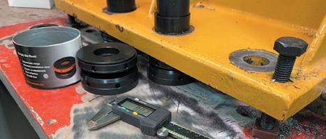
2.1 CHECK THE GAP HEIGHT AND BOLT HOLE AGAINST THE SELECTED ROTACHOCK®


Measure the available gap height of each position and measure the diameter of the bolt hole. The gap height should be within the adjustment range of the selected RotaChock®, and the foundation bolt diameter must fit through the selected RotaChock®
2.3 CHECK THAT THE ROTACHOCK® DOES NOT ROCK OR WOBBLE ON THE FOUNDATION

We call this the ‘rocker’ or ‘wobbling’ check. After positioning the RotaChock® in its final location, apply hand load to the top of the RotaChock®, and try to rock the RotaChock® from side to side. In case it rocks, investigate the cause and correct it. In most instances, surface preparation only involves some local sanding.
2.2 CHECK THAT THE ROTACHOCK® CONTACT AREA IS SUPPORTED


Ensure that the foundation width is equal to or larger than the RotaChock® diameter. The foundation must entirely support the RotaChock® bottom part. The machine foot should cover at least the thread diameter of the RotaChock® top part.
2.4 CHECK THAT THE ROTACHOCK® PASSES THE FEELER GAUGE TEST


Push down on the RotaChock® and use a feeler gauge blade of 0,05 mm / 0,002” around the circumference of the bottom part. The acceptable mounting surface check has succeeded if the feeler gauge blade does not pass entirely through the interface area.


1
1 2 3 4 5 6 TO INSTALL ROTACHOCK® YOU MUST COMPLETE FOLLOWING STEPS: Clean Check Alignment Fill the GAP Install foundation bolts Check final alignment
Scan QR
for the installation video INSTALLATION INSTRUCTIONS 21 ROTACHOCK ® INFORMATION BOOK
4


Ensure that alignment is within the machine target requirements for cold alignment, thermal growth, and crankshaft deflections using jacking devices. Because the RotaChock® is a mechanical device, align the unit 0,05 mm / 0,002” above the target. The 0,05 mm / 0,002” is a nominal dimension to accommodate the lubricant’s extrusion in the RotaChock® internal surfaces.
RotaChock® is a mounting chock, and we do not recommend using it as a lifting device for alignment.


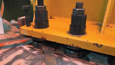
FILL THE GAP WITH ROTACHOCK® AND RELEASE THE VERTICAL JACKING BOLTS


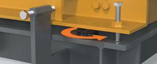
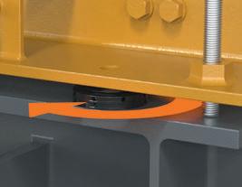
Unpack the RotaChock®; the unit is marked with a batch number for traceability purposes. Place the RotaChock® in position, generally concentrically with the bolt hole, and batch number facing outwards. Fit the RotaChock® by rotating it anticlockwise to fill the gap.

You can use your hand, RotaChock® Adjustment Tools, or your own set of tools for the adjustment.

The force required to tighten the RotaChock® in place within the gap is minimal (10 - 15 Nm.) The buttress thread’s self-locking characteristics ensure no need for a mechanical locking device to prevent the RotaChock® from rotating under load.
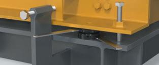
Once all RotaChock® are installed, take the load off the vertical jacking bolts.
3 ALIGNMENT
22
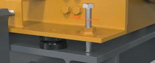
INSTALL FOUNDATION BOLTS

In the absence of any guidance, we prefer 70% of the foundation bolts’ proof strength. Check the design instruction on page 17 for further instructions regarding bolt selection. The table on the right shows the tightening torques and clamping lengths for 8.8-grade bolts lubricated with light machine oil, ISO metric screw thread, and coarse pitch.
Without OEM instructions for a tightening sequence: tighten the first bolt with the required torque. Then move directly criss-cross and continue the sequence until all the bolts have been tightened.


CHECK FINAL ALIGNMENT


After tightening all the foundation bolts to the required torque, check the final alignment. The alignment should be within the cold alignment target tolerances.


5
Install the foundation bolt, preferably from the bottom up, and tighten the foundation bolts per the recommended OEM sequence and tightening torque. Select 8.8-grade bolt per ISO 273 Recommended bolt torque (µTH = 0,15) Nm M10 60 M12 100 M14 150 M16 200 M18 300 M20 400 M22 600 M24 750 M27 1.100 M30 1.500 M33 2.000 M36 2.600 M39 3.400 M42 4.200 M45 5.200 M48 6.300 M52 8.200 M56 10.000 M60 12.500 M64 15.000 M68 18.000 M72 22.000 M76 26.500 1 3 4 2
23 ROTACHOCK ® INFORMATION BOOK
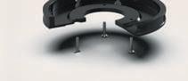
SLIMLINE INSTALLATION NOTES


RotaChock® SlimLine is made up of 5 parts:


Top ring with a convex surface,


Middle ring with a male thread and a concave cavity on top.
Drive ring with a female thread.
Base ring for fixing the drive pins.
Drive pins for locking the center ring while rotating the drive ring.
In contrast to the RotaChock® BasicLine, the RotaChock® SlimLine works clockwise. Just follow the steps shown on the previous pages, but in step 4, fit the RotaChock® SlimLine by rotating it clockwise to fill the gap. The correct installation must look like this:
Scan QR for installation video
ROTACHOCK® MOUNTING PLATE INSTALLATION NOTES


Installation of the RotaChock® Mounting Plate is straightforward, and the steps are the same as for other RotaChock® types. Just follow the installation instructions from your resilient mount supplier. When it is time to install the chocks, continue with the RotaChock® installation procedure.
In addition to the checks shown in step 2, check if your RotaChock® Mounting Plate matches the resilient mount’s bolt pattern.
Remember to fit the RotaChock® SlimLine by rotating it clockwise!
Scan QR for installation video


After releasing the jacking bolts and before tightening the foundation bolts, there should not be any gap between the RotaChock® Mounting Plate and the resilient mount’s bottom plate.
Remember always to check if no GAP remains between the RotaChock® Mounting Plate and the bottom plate of the resilient mount.

ROTACHOCK®
24
ROTACHOCK® APPLICATIONS & INDUSTRIES


RotaChock® is being used for mounting all types of rotating and critically aligned equipment. Every kind of installation has once been successfully mounted on RotaChock®. From wind, gas, and steam turbines to engines, cranes, winches, and rolling mills. The most frequently RotaChock® mounted applications are:
CHECK OUR COMPLETE PORTFOLIO OF APPLICATIONS AT WWW.ROTACHOCK.COM 25 ROTACHOCK ® INFORMATION BOOK
PACKAGERS


Packagers are builders of installations where a driver and driven component are installed on a frame skid. It can be a combination of the applications as shown on the left. Examples are an electric motor combined with a pump, serving as a pump set across industries ranging from public utilities to mining. Or a combustion engine/ generator combination, providing emergency power to a hospital.
World-leading OEMs like Caterpillar, GE, Wärtsilä, and Rolls Royce have standardized the use of adjustable chocks in their skid design. These installations require realignment on multiple occasions during their life cycle. Thanks to RotaChock®, these skids can be easily adjusted upon arrival at their final destination and during their entire service life.
MARINE
In marine applications, RotaChock® is the perfect mounting solution for propulsion installations. When realignment is necessary, the possibility to readjust the chock creates significant time saving for shipowners. RotaChock® significantly shortens their maintenance breaks and improves service life. But also, shipyards prefer RotaChock® when building new vessels. It allows for final alignment after the launch when the ship is already afloat.
RotaChock® mounted applications are seen in a broad range of industries. RotaChock® serves industries from power generation and offshore to marine and nuclear in prestigious projects like:
NUCLEAR


At a nuclear plant, RotaChock® are mounted under generators of 423.000 kilos producing over 1.350.000 kWh.

POWER GENERATION
Karadeniz Powerships are generating hundreds of MW’s of electricity with RotaChock® mounted gensets.

MARINE
The largest cruise ship built, Oasis of the Seas, serving 7.000 passengers, has RotaChock® mounted equipment.

OFFSHORE
Shell’s Appomattox is relying on RotaChock® mounted compressor sets in the Gulf of Mexico

CHECK OUR COMPLETE PORTFOLIO OF SUCCESS STORIES AT ROTACHOCK.COM
26
PORTFOLIO 27 ROTACHOCK ® INFORMATION BOOK
CHECK OUR COMPLETE PORTFOLIO AT ROTACHOCK.COM 28
F REQUENTLY A SKED Q UESTIONS
› 1. I need chocks with additional height
› 2. Can a shim/plate/spacer be added below the RotaChock®?
› 3. How to mount RotaChock® underneath a hollow/ U-shaped machine foot?
› 4. Is it possible to mount RotaChock® between aluminum machine foot or foundation?
› 5. I need an extended adjustment range, is there a limit to the adjustment height?
› 6. How to reduce the height of the RotaChock®?
› 7. How to enlarge the bolt hole of the RotaChock®?
› 8. How much support does the RotaChock® need?
› 9. What is the recommended foundation thickness?
› 10. What about i-Beams?
› 11. Can I tack weld the RotaChock® to the foundation?
› 12. How can we use fitted bolts in combination with RotaChock®?
› 13. How can we use dowel pins in combination with RotaChock®?
› 14. Can I install RotaChock® upside down?
› 15. Can I install the foundation bolt from the top?
› 16. Can I jack or align my machine with the RotaChock®?
› 17. Can I install the four corners first, then the other RotaChock®?
› 18. How do we prevent the chock from rotating, do i need to lock or secure the RotaChock®?
› 19. What is the most significant load in the installation?
› 20. How is it possible that my foundation bolts are loosening?
› 21. What is the difference between rigid & resilient mounting?
› 22. How does RotaChock® conduct sound compared to epoxy resin chocks, shims, or steel-fitted blocks?
› 23. What is your advice regarding corrosion protection?

› 24. Can we use a coating on the RotaChock®?
› 25. Do you use grease on RotaChock®?
› 26. What about lubricating the foundation bolts?
› 27. How to mount on concrete?
› 28. What to do if my RotaChock® is frozen or hard to turn?
› 29. Should I perform a Soft-Foot check after installing RotaChock®?
› 30. During service life, do I have to check the RotaChock®?
› 31. What is most cost-effective: epoxy resin, steel-fitted blocks, or RotaChock®?
› 32. What is the shelf life for RotaChock®?
› 33. Can we install the RotaChock® on top of a threaded block?
› 34. What bolt torque do we have to apply?
1. I NEED CHOCKS WITH ADDITIONAL HEIGHT
There are three options if additional height is required in your installation:
A TALL TOP RING
When additional height is required in the range of 5-25 mm, we can supply taller top rings for the RotaChock® BasicLine/SlimLine/Mounting plate. These can replace the ones originally supplied and provide additional height. We stock these taller top rings for the full range at several thicknesses for maximum flexibility.
B SPACER RING
If required, a spacer ring can be placed underneath the RotaChock® BasicLine & SlimLine and the foundation. We stock these Spacer Rings for the full range of several thicknesses for maximum flexibility.
C ROTACHOCK® TALL LINE
For specific applications, we recommend using the RotaChock® Tall Line, which has an extended bottom ring. However, there are some considerations for using Tall Line configurations, i.e., when thrust or shear forces are involved.
As a rule of thumb for all three options: the height of the chock should never exceed the diameter. For example, the maximum height of the RC4-BasicLine, which is 102 mm in diameter, should not exceed 102 mm.
Maximum height = 53, which means that the maximum allowable additional height is 49 mm. From a design viewpoint, the best option is A. The number of mating surfaces should be minimized because this influences the final clamping force.
29 ROTACHOCK ® INFORMATION BOOK
2. CAN A SHIM/PLATE/SPACER BE ADDED BELOW THE ROTACHOCK®?
Yes. However, some care must be taken during installation. Below are some scenarios that we have seen over the years:
4. IS IT POSSIBLE TO MOUNT ROTACHOCK® BETWEEN ALUMINUM MACHINE FOOT OR FOUNDATION?
Yes, it’s possible. But the surface pressure on aluminum needs to be at an acceptable level. Please contact our engineering team to calculate the allowable surface pressure for your aluminum application.
SINGLE SHIM/ 2 CHOCKS MULTIPLE SHIMS
5. I NEED AN EXTENDED ADJUSTMENT RANGE, IS THERE A LIMIT TO THE ADJUSTMENT HEIGHT?
BENT SHIMS WARPED FOUNDATION
There are two prominent design notes for the use of shims/ plates/spacers underneath RotaChock®:
› The foundation and additional plating need to be flat. Any deformation means the installation may warp/bend, resulting in Soft-Foot. Please beware of an increased risk of warping/twisting when one shim/plate is placed under multiple chocks. When torquing the first RotaChock® , the added plate may warp and twist. Note that this may also occur when welding in the immediate vicinity. Heat may deform the steel and result in Soft-Foot.
› The number of mating surfaces must be kept to a minimum because this influences the final clamping force. Adding more separate pieces in the clamping assembly should be avoided.
Please check FAQ #1 for our preferred solutions if you need increased height.
3. HOW TO MOUNT ROTACHOCK® UNDERNEATH A HOLLOW/U-SHAPED MACHINE FOOT?
RotaChock® can be mounted underneath any unevenly shaped machine foot by adding a steel plate between the foot and the RotaChock®. Below is an example of an E-motor with a U-foot:
We can offer the RotaChock® Extended Adjustment Range (EAR) when more adjustability is required. Like the RotaChock® Tall Line, it has an extended bottom ring, but the EAR also has an extended center ring. The EAR increases the package’s flexibility in the design of the installation or a system that changes during its lifecycle. Please contact your RotaChock® distributor for further details on this product range and its capabilities.
6. HOW TO REDUCE THE HEIGHT OF THE ROTACHOCK®?
RotaChock® BasicLine and Spherical Spacer can easily be machined in a lathe. First, install the assembled chock into the lathe’s chuck (only the bottom and center rings). Then remove material from the bottom of both rings simultaneously until you reach the required height. The procedure is part of the classification type approval, so no special permission is required. Note that the adjustment range is also reduced. For every mm you take off, you will lose one mm of adjustment range. At the minimum reduced height, only one mm of adjustment remains. The minimum reduced heights can be found in the RotaChock® dimension charts. If reducing the height is not enough, switch to the RotaChock® SlimLine.

7. HOW TO ENLARGE THE BOLT HOLE OF THE ROTACHOCK®?
You can find the optional foundation bolt size in the dimension charts; this is the maximum allowed bolt size for the RotaChock® when the bolt hole is enlarged. Rule of thumb: maximum enlargement is optional bolt size + 1 mm.
For example, RC2-BasicLine has an inside diameter of Ø17, and the optional bolt size is M18. When adding one mm, the inner diameter can be enlarged to a maximum of Ø19.
8. HOW MUCH SUPPORT DOES THE ROTACHOCK® NEED?
The bottom part should always be entirely supported; not having the base ring supported may distort the base’s thread. The thread diameter of the RotaChock® should be fully underneath the machine foot. Both diameters can be found in the dimension chart.
30
9. WHAT IS THE RECOMMENDED FOUNDATION THICKNESS?
A rule of thumb is to match the foundation bolt diameter; if the bolt diameter is 1”, then the foundation should be at least 1” thick. Also, ensure that gussets are used to tie the load path to the foundation. In case of a large engine mass, angle the gussets outwards to increase the foundation’s rigidity.
10. WHAT ABOUT I-BEAMS?
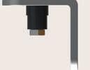
Some installations require cut-outs to be made in i-beam webs to install the foundation bolts; below an example.
Incorrect: the recess is too large for the chock’s diameter. The removed web material is too close to the mounting flange. The results are a significantly reduced beam strength and system that acts as though it has Soft-Foot.
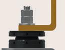
13. HOW CAN WE USE DOWEL PINS IN COMBINATION WITH ROTACHOCK®?

You can use a welded riser block or a nut and bolt method like below:
Welded riser block option
Nut and bolt option
When you have completed all the steps from the installation instruction, weld a steel block that is 1 mm lower than the gap near the chock, and drill a hole through the machine foot into the block and install a dowel pin.
14. CAN I INSTALL ROTACHOCK® UPSIDE DOWN?
Correct: this is is an improved access cut-out, which maintains the strength of the mounting flange. Add a spacer to access the nut for ease of maintenance for the lifecycle.
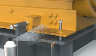
11. CAN I TACK WELD THE ROTACHOCK® TO THE FOUNDATION?
Do not weld anything to or around the RotaChock®. Also, avoid welding in the immediate vicinity, as heat may deform the steel structure and open the possibility of Soft-Foot. When welding is required, please ensure proper earthing.
12. HOW CAN WE USE FITTED BOLTS IN COMBINATION WITH ROTACHOCK®?
If fitted bolts are required per OEM instructions, we advise only to ream the machine foot and foundation. If a larger bolt hole in the chock is needed to fit the bolt, please check FAQ #7
That’s okay, and it’s a perfect solution if the foot or foundation’s design requires it.
15. CAN I INSTALL THE FOUNDATION BOLT FROM THE TOP?
Yes, that’s possible. But bear in mind that for installation, it’s easier to install the nuts from the top.
16. CAN I JACK OR ALIGN MY MACHINE WITH THE ROTACHOCK®?
RotaChock® is a gap filler, and we do not recommend using it as a lifting device for alignment. Use jacking bolts or other devices for alignment, and fill the remaining gap with RotaChock®
17. CAN I INSTALL THE FOUR CORNERS FIRST, THEN THE OTHER ROTACHOCK®?
Yes, for alignment purposes, but not for the final alignment. We recommend using the vertical jacking bolts when carrying out the final alignment and install RotaChock® as described in the installation instructions.
18. HOW DO WE PREVENT THE CHOCK FROM ROTATING, DO I NEED TO LOCK OR SECURE THE ROTACHOCK®?
When you release the vertical jacking bolts during installation, the weight of the machine compresses the chock.
The RotaChock® thread locks itself due to friction in the thread. No other locking methods are required.
19. WHAT IS THE MOST SIGNIFICANT LOAD IN THE INSTALLATION?
The bolt tension is by far the highest load in the installation. In general, around 90% of the total load on the RotaChock® is a result of bolt tension. All other loads, such as machine loads created by weight and torque, are less significant.
31 ROTACHOCK ® INFORMATION BOOK
20. HOW IS IT POSSIBLE THAT MY FOUNDATION BOLTS ARE LOOSENING?
The first two questions which we always ask back are: Is there enough stretch in your bolts? Are your bolts straight and not bending? See the design pages on 17 for further instructions. In the field, we experience a high spread on tensioners, in some cases over 40%. Bolt lubrication is also a significant factor. There are several reasons for bolts loosening; contact our engineering team for support.
21. WHAT IS THE DIFFERENCE BETWEEN RIGID & RESILIENT MOUNTING? RIGID MOUNTING
All equipment, especially rotating machinery, is required by the manufacturer to be affixed to a structural base. Rigid mounting means creating a solid steel plate (foundation) with a machined top surface, grouted to a concrete foundation or welded to a steel structure, and supporting and maintaining the equipment’s alignment. The gap between the foundation and its machine foot can be filled using several different processes and products. In the philosophy of RotaChock®, it’s our goal to create a rigid coplanar surface for the machine that exceeds the OEM requirements for Soft-Foot, and that must retain the equipment’s position after final alignment.
RESILIENT MOUNTING
Structure-borne noise and vibration are produced by an engine’s moving parts and the combustion process. These various forms of vibrations like noise, vibration, or shocks cause comfort disturbance onboard ships. Resilient mounts are the most effective option where noise and vibrations transmitted through to the vessel’s hull must be reduced to an absolute minimum. This reduction contributes significantly to crew and passenger comfort, especially on ferries, cruise liners, or yachts.
The installation of resilient mounts can be challenging. The rubber mount’s base plate must be aligned perfectly parallel to the machine foot to ensure optimal vibration damping. Fortunately, we have a solution to that problem. Please check page 13 for detailed information about our RotaChock® Mounting Plate.
22. HOW DOES ROTACHOCK® CONDUCT SOUND COMPARED TO EPOXY RESIN CHOCKS, SHIMS, OR STEEL-FITTED BLOCKS?
Since RotaChock® is a mechanically stiff steel chock, the sound propagation characteristics are comparable to those of resin chocks and steel-fitted blocks. However, the self-leveling top plate of the RotaChock® means the actual sound performance will often outclass fabricated steel-fitted blocks or shims.
23. WHAT IS YOUR ADVICE REGARDING CORROSION PROTECTION?
The standard RotaChock® types are Anti-Corrosion Enhanced. You will find more information on this process on page 7. We advise stainless steel (316L) for maximum protection against corrosion in extreme environments such as offshore and deck applications. In case of specific corrosion requirements, please contact our engineering team.
24. CAN WE USE A COATING ON THE ROTACHOCK®?
In some applications, the complete installation is coated, including RotaChock®. Please take caution during application since paint sprayed on the thread can prevent the RotaChock® from rotating.
25. DO YOU USE GREASE ON ROTACHOCK®?
All RotaChock® that are Anti-Corrosion Enhanced undergo a final dip in machine oil. They can still be oily when removed from the packaging. It does not harm the final installation and can be left on the RotaChock®. If preferred, it can be removed with a cloth.
All Stainless Steel RotaChock® have the threads and spherical top parts lubricated with Molykote® D Anti-Seize Paste or similar. This paste should not be removed since it prevents the parts from galling and seizing.
All non-treated (carbon) steel RotaChock® have the threads and spherical top part lubricated with Molykote® P-37 AntiSeize Paste or similar. It must remain on the RotaChock® when installed. The outer surfaces are coated with LPS 3® Premier Rust Inhibitor or similar. This should be cleaned off the top and base surface of the chock.
26. WHAT ABOUT LUBRICATING THE FOUNDATION BOLTS?
Many industries and manufacturers have their bolting and lubrication preferences. Changing the lubrication agent impacts the friction coefficient and the resulting tightening torque. No matter what lubrication is used, note that we recommend that the foundation bolt has a minimum bolt stretch of 0,20 mm.
27. HOW TO MOUNT ON CONCRETE?
Use a steel plate of sufficient surface and thickness so that the surface pressure on concrete is of an acceptable level. When mounting RotaChock® directly on concrete, first check the existing concrete’s allowable surface pressure.
28 . WHAT TO DO IF MY ROTACHOCK® IS FROZEN OR HARD TO TURN?
Dirt or debris may have infiltrated the thread of the RotaChock®. Disassemble the chock, inspect the threads, and clean it using a rag and WD-40 or similar. In most cases, this will solve the issue.
In cases where the chock is completely seized (e.g., because grease in the threads has solidified due to a reaction with cleaning solutions used to degrease the equipment), remove the chock and carefully apply heat (never exceed 250C/480F). Heat will cause the grease to liquefy. Thoroughly clean the threads and use a nickel-based anti-seize before reinstallation.
Spotted some damage to the thread? Obtain a set of working spares from your warehouse. Have ready access to a set of spares. Take out the old chock and replace it with a working set and finish the job. Back at the shop, refurbish the old chocks at your leisure and set them up for the next occasion.
32
29. SHOULD I PERFORM A SOFT-FOOT CHECK AFTER INSTALLING ROTACHOCK®?


If the design and installation instructions of RotaChock® are followed, a Soft-Foot should not be possible. However, if a final Soft-Foot check is preferred, these are the instructions:

1. After final alignment, when the bolts have been tightened to the final torque, install a dial indicator near bolt position #1 and set it to zero
2. When loosening the bolt, the indicator should not move more than 0,05 mm/0,002.”


3. If the indicator moves more than 0,05 mm/0,002”, repeat the alignment and recheck your bolting plan

32. WHAT IS THE SHELF LIFE FOR ROTACHOCK®?


People are often confused because they have experience with epoxy resins, where it’s essential to check the date of production before mixing. However, RotaChock is made of steel and will not lose its mechanical properties or deteriorate. Therefore, RotaChock® has no expiry date and has an unlimited shelf life. Carbon steel is the world’s most recycled material and can be reused indefinitely without loss of mechanical properties. Due to its durability, RotaChock® has a long service life and can be recycled and used in other products, saving resources in the process. Note: RotaChock should be stored under dry conditions and in its original packaging.
33. CAN WE INSTALL THE ROTACHOCK® ON TOP OF A THREADED BLOCK?
Yes, this is possible. However, the rule of thumb: the thread depth should be at least 1,5x the thread diameter. For example: a M30 bolt should have a 45 mm. thread engagement.


34. WHAT BOLT TORQUE DO WE HAVE TO APPLY?
The RotaChock® itself should be tightened hand-tight (10-15 Nm). For the foundation bolt you can find the recommended bolt torques on page 23.

30. DURING SERVICE LIFE, DO I HAVE TO CHECK THE ROTACHOCK®?
The RotaChock® itself does not have to be checked during service. We advise following the OEM maintenance instructions and guidelines for checking the mounting fasteners’ torque.
Without OEM guidelines, we recommend that the mounting fasteners’ torque is checked after 100 hours of normal load operations.
31. WHAT IS MOST COST-EFFECTIVE: EPOXY RESIN, STEEL-FITTED BLOCKS, OR ROTACHOCK®?


RotaChock® is the most cost-effective and the best lifecycle decision for rotating equipment. Soft-Foot is solved, and your equipment can be realigned at any required moment. Our engineering team has decades of experience with aligning and mounting machines and has worked with many other chocking products. If not convinced, we encourage you to sit down with us and prepare a cost comparison between epoxy resins, steel-fitted blocks, and RotaChock®
33 ROTACHOCK ® INFORMATION BOOK
34
ABOUT US


CHOCK DESIGN
As the name says, we design chocks – steel mounts for machinery foundations. Chock Design is a global powerhouse with a wealth of experience, expertise, and understanding of its markets. We do not only offer products: we also use our products to provide solutions. And we can do so, thanks to our many years of experience in a wide range of businesses worldwide. And maybe even more importantly, thanks to the fact that we design our products based on our own practical experience.
Chock Design revolutionized the chock market with its pragmatic approach and innovative product design. As the leader in the sector, we continue developing user-friendly and time-saving chock solutions.

GLOBAL COMPETENCE
RotaChock® is distributed worldwide via a network of multiskilled alignment and mounting experts. This global covering distributor network ensures access to a whole support team, from design engineers at the knowledge centers to service engineers in the field.


Distributors know and understand their local market, customers, and challenges. With this local presence, we offer fast response time and the availability of experienced engineers. They have the expertise and equipment to detect and fix problems quickly.


ADVANCED ENGINEERING SOLUTIONS

Our international team of mechanical designers and application engineers is ready and waiting for your challenge. Our team is the most reliable partner for chocking solutions from design and engineering to performance and support. Together, we can arrange the correct setup and alignment of your machinery.
Our team can perform an in-depth structural analysis for complex installations in which both the machinery and the foundations are subject to dynamic forces, including computer modeling and finite element analyses. These advanced engineering services are helpful for new installations and proved their worth in resolving problems in existing applications.
We help you to keep your machinery ready and running.
35 ROTACHOCK ® INFORMATION BOOK


PLEASE CONTACT US VIA THE BELOW ADDRESSES, AND YOU WILL BE PUT IN CONTACT WITH YOUR LOCAL DISTRIBUTOR. Documentation Videos Download center 2D/3D drawings RotaChock® Selection tool WhatsApp support Authorized distributors WWW.ROTACHOCK.COM +31 (0) 10 268 8018 INFO@ROTACHOCK.COM CONTACT ® RotaChock is a registered trademark of Chock Design B.V. © Chock Design B.V. 2022 The contents of this publication are the copyright of the publisher and may not be reproduced (even extracts) without prior written permission having been granted. Every care has been taken to ensure the accuracy of the information in this publication. Still, no liability can be accepted forany loss or damage, whether direct, indirect, or consequential, arising from using the information contained herein. Publication RotaChock® Information Book Edition 10/2022 info@rotachock.com www.rotachock.com 36


www.rotachock.com Edition: 10/2022
