The graphic illustrations in this manual are provided for purposes of better presentation of content, they are not necessarily true to scale and can deviate slightly from the actual version of the T-Series HA/DS T35/T60 _ T50/T90 _ T75/T140_T130/T170.
The position numbers used in the illustrations and action steps correspond to the position numbers of the drawings. This assembly manual satisfies the requirements of DIN 82079. It is subject to a permanent revision process. Subject to change without notice. Errors and omissions excepted.
1.2 EXPLANATION OF SYMBOLS
Safety instructions are indicated by symbols in this operating manual. The safety instructions are introduced by signal words that express the scope of the hazard.
The safety instructions must be strictly complied with, you must act prudently to prevent accidents, personal injury, and material damage.
SYMBOLS
WARNING!
indicates a possible dangerous situation that can result in death or serious injury if it is not avoided.
PROHIBITORY!
NOTE!
indicates useful tips and recommendations, as well as information for efficient and trouble-free operation.
1.3 LIMITATION OF LIABILITY
All information and instructions in this operating manual have been provided under due consideration of applicable guidelines, the current state of technology, as well as our many years of experience.
The manufacturer assumes no liability for damage due to:
› Failure to comply with the instructions in the operating manual
› Non-intended use
› Deployment of untrained personnel
› Unauthorized conversions
› Technical changes
› Use of non-approved spare parts
› Use in case of recognizable defects
The current scope of delivery can vary from the explanations and graphic representations provided in this manual in the case of special versions, if supplemental order options are desired, or on the basis of the latest technical changes. The agreed obligations in the delivery contract, the general terms and conditions, as well as delivery conditions of the manufacturer, and the statutory regulations valid at the time the contract was concluded, apply.
1.4 SPARE PARTS
Order spare parts via authorized dealers or directly from customer service. See section “Customer service” for the contact address.
Specify the following information when ordering spare parts:
› Order number or consignment number
› Drawing number
› Parts list number
1.5
CUSTOMER SERVICE
Our customer service organization is available for technical information. In addition our employees are always interested in new information and experiences associated with the application that could be valuable for the improvement of our products.
Incorrect or defective spare parts can cause damage, malfunction, or total failure; they can also impair safety.
Only use manufacturer’s original spare parts.
1.6
WARRANTY TERMS
The warranty terms are included in the manufacturer’s terms and conditions.
The responsible contact is always available at the following contact address:
Chock Design B.V. Beursplein 37 3011 AA Rotterdam The Netherlands
VULKAN Kupplungs- und Getriebebau
Bernhard Hackforth GmbH & Co. KG
Heerstrasse 66 44653 Herne Germany
2 SAFETY
2.1 RESPONSIBILITY OF THE OWNER
This section provides an overview of all the important safety aspects for optimal protection of personnel, as well as for safe and trouble-free operation.
Significant hazards can occur if the handling instructions and safety instructions in this manual are not complied with.
The T-Series HA/DS T35/T60 _ T50/T90 _ T75/T140_T130/ T170 is used in commercial operation. Consequently the owner of the T-Series HA/DS T35/T60 _ T50/T90 _ T75/T140_ T130/T170 is subject to legal industrial safety obligations.
In addition to the occupational health and safety instructions in this assembly manual, generally valid safety and accident protection guidelines, and environmental protection guidelines must be complied with for the area of implementation of the T-Series HA/DS T35/T60 _ T50/T90 _ T75/T140_T130/T170 resilient mount.
In this regard the following particularly applies:
› The owner must inform himself of applicable occupational health and safety regulations, and in a hazard analysis identify other hazards that may exist at the installation site of the resilient mounts due to the special work conditions. The owner must convert this information relative to hazards into operating instructions for operation of the resilient mounts.
› The owner must ensure during the entire implementation period of the resilient mounts that the operating instructions created by the owner correspond to the current state of legislation, and if necessary the owner must adapt these operating instructions.
› The owner must clearly regulate and specify responsibilities for installation, operation, maintenance, and cleaning.
› The owner must ensure that all employees who handle the resilient mounts have read and understood the assembly manual. In addition, the owner must train personnel and inform them of hazards at regular intervals.
› The owner must provide the required protective equipment for personnel.
Moreover, the owner is responsible for ensuring that the resilient mounts are always in technically faultless condition; consequently the following applies:
› The owner must ensure that the maintenance intervals described in this assembly manual are complied with.
› The owner must have all safety devices inspected regularly for function and for completeness.
2.2 INTENDED USE
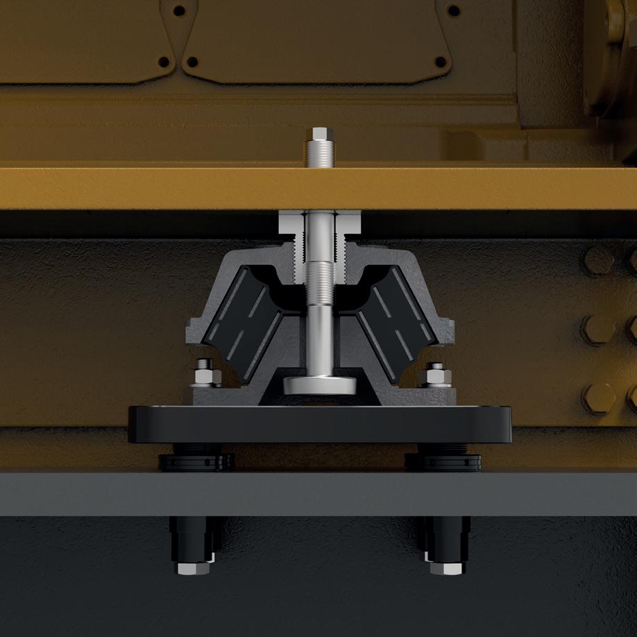
The highly elastic mounts of the T Series have been specifically developed to do justice to the most stringent requirements with respect to insulation and comfort.
At the same time they offer a high degree of safety with their versatile designs. The load is borne by rubber elements with the help of shear and compression strain.
Several rubber compounds are available, as a result of which optimal adjustment of the vibration response of the mounted machine can be ensured.
Several versions are available in order to meet the requirements of a given system and all mounts have a built-in centralised limiter that restricts the vertical and radial displacements.
The centralised limiter protects the important connections of the system against extreme displacements that occur owing to the ship’s movements
Claims of any type due to damage arising from non-intended use are excluded. The owner is solely liable for all damage in the case of non-intended use.
Any use that extends beyond intended use and/ or other use of the coupling can cause hazardous situations.
Therefore:
› Use the resilient mounts as intended.
› Strictly comply with all instructions in this operating manual.
› Use outside of the originally intended application case.
› Overloading the coupling by exceeding the limit values specified in the technical data.
› Use of a resilient mount that does not bear an Ex designation, and thus is not designed for use in explosive atmospheres, in the Ex area.
3 STRUCTURE AND FUNCTION
3.3 APPLICATIONS
The highly elastic mounts of the T series have been specifically developed to do justice to the most stringent requirements with respect to insulation and comfort. At the same time, they offer a
The load is borne by rubber elements with the help of shear and compression strain. Several rubber compounds are available, as a result of which optimal adjustment of the vibration response of the mounted machine can be ensured. Regarding the shape it has the ability to impact pressure and thrust load. The element is built from natural caoutchouc and can be dedicated from
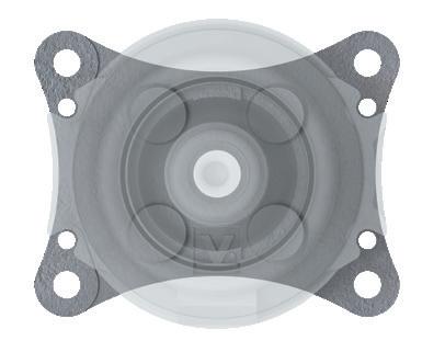
All mounts have a built-in centralized limiter that restricts the vertical and radial displacements. The centralized limiter protects the important connections of the system against extreme displacements that occur owing to the ship’s movements. The T-series is unique in it’s design thanks to it partible central limiter, this greatly improves installation and service life as the mount can be easily placed without jacking the application.
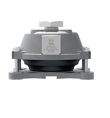
PRE-TENSIONED DESIGN
Pre-tensioned delivered mounts assure a parallel position of top to base casting and reduce creep deformations during the alignment process. This results in a predictable creep behavior, saving time during alignment. The main benefits are thanks to the use of high-grade materials with standard features to assure cost-efficient installation and lifetime of the mounts. In addition, it results in a low cost of ownership aside from the excellent vibration reduction properties. Thanks to this unique pre-tensioned design, it’s also possible to pre-tension the mount to meet a specific load for an application.
3.2 SYSTEM BENEFITS
› Built-in centralized limiter to protect the system in extreme situations.
› Selection of natural rubber compounds for optimal adjustment of the response to vibrations.
› The cast parts and screws made of high-strength materials have been designed with a high factor of safety with respect to the nominal load.
› Linear stiffness characteristic in the nominal load range.
› Savings in time for installation with the help of pre-stressed bolts.
› Type Approval by leading classification companies.
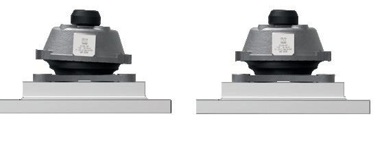
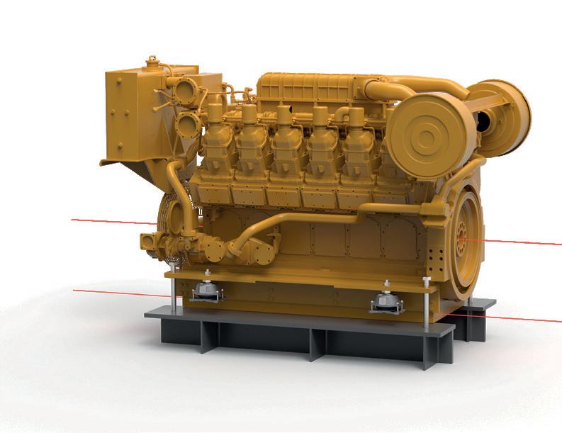
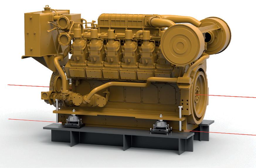
The VULKAN T-series can be used in serval applications and setups. A typical application can be drive motor mounts, Generator frame units or diesel-electric drive units.
These mounts can be used for all appliances that generate vibrations that must be isolated to the environment. Most of these mounts end us in single elastic suspension sets. But also, double suspensions are used to meet extremely high demands on vibration isolation at, for instance, mega yachts and research vessels.
These T-series are mainly used in marine applications thanks to the design with integrated displacement limiters and purposedesigned features like pre-tension devices and Type Approvals of all major classification societies.
3.4
CERTIFICATION
Both product lines are manufactured in ISO-certified machine shops, where modern CNC equipment and state of the aft measurement tools are used to guarantee a constant and highquality level. Production is assessed annually for approval by certification institutes and backed up by audits from users, who are industry leaders. With the quality systems in place, all markets can be served, from navy to nuclear.
The two independent product lines are been approved by various classification authorities, enabling the use underneath propulsion machinery and auxiliary installations onboard ships without having to go through a lengthy plan approval application.
The VULKAN T-series and RotaChock Mounting Plate have been “Type Approved” by all major classification societies, like:
4 EXPLODED DRAWING / SPARE PARTS LIST
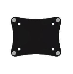
The Rotachock Mounting Plate was developed in close cooperation with leading developers of VULKAN T-series. For the full T-series range a standard design was made where we integrated four RotaChock in the corners of a stiff Mounting Plate. These designs are standardized and do not need any further engineering or selection. In table 1 you can find the compatibility.
5.3 PACKAGING ABOUT THE PACKAGING
We recommend not to destroy the original packaging and to remove it just prior to assembly. Deviant behaviour must not lead to premature product ageing, damage or restrictions in function and service life. The measures necessary for this must be realized effectively until the product is installed. Individual packed goods are packaged according to the expected transport conditions. Environmentally-friendly materials have been used exclusively for the packaging. Packaging should protect the specific components from transport damage, corrosion and other damage until assembly.
HANDLING PACKAGING MATERIALS
Dispose of packaging materials in accordance with the respectively valid statutory regulations and local guidelines.
6 INSTALLATION OPTIONS
A chock is the interface between the foundation and machine foot, or in this case, the resilient mount. You need to secure the flexible mounted machinery equipment to the foundation, and it must retain position after final alignment.
There are several options for chocks in the sector, like steel-fitted chocks, epoxy resin chocks or RotaChock.
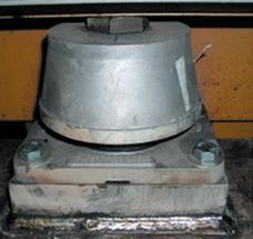
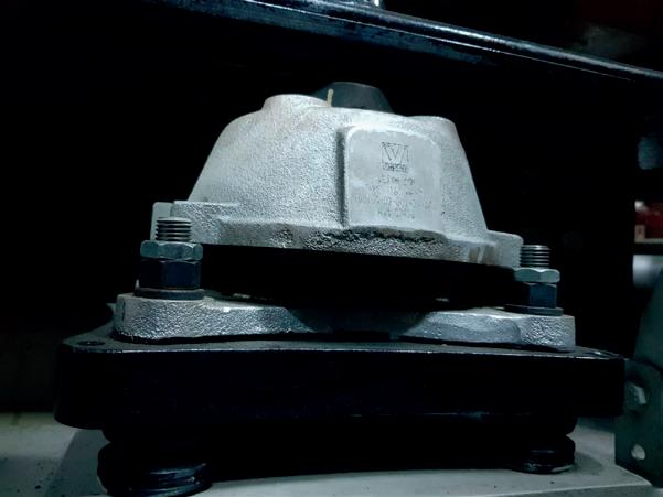
STEEL-FITTED CHOCKS
In addition, for resilient mounts is important that the rubber mount’s base plate must be aligned perfectly parallel to the machine foot to ensure optimal vibration damping.
After alignment, the height between VULKAN T-series and foundation is 3D measured, and a steel fitted block is produced in a high-end machine shop. After production, the steel fitted blocks are placed accurately between the resilient mount and foundation. You need to blue fit and adjust to have optimum contact surface because otherwise there is a high chance for Soft-Foot. After this lengthy and specialistic fitting process, the foundation’s bolts can be torqued, and installation finalized.
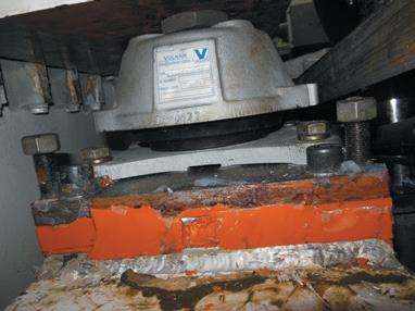
EPOXY RESIN CHOCKS
First you need to engineer and calculate the chocking plan to not overload the epoxy resin chock. After a fair amount of engineering work, you can start by bolting the VULKAN T-series to an pre-machined adapter plate. After alignment, the chocking area is dammed, and certified mechanics pour a two-component epoxy resin between the adapter plate and foundation. After the epoxy resin’s lengthy hardening process, the foundation’s bolts can be torqued, and installation finalized.
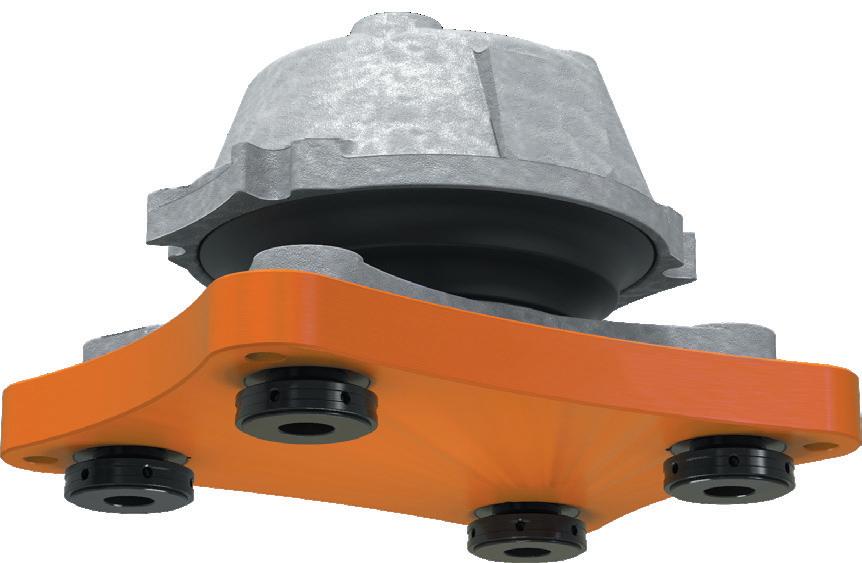
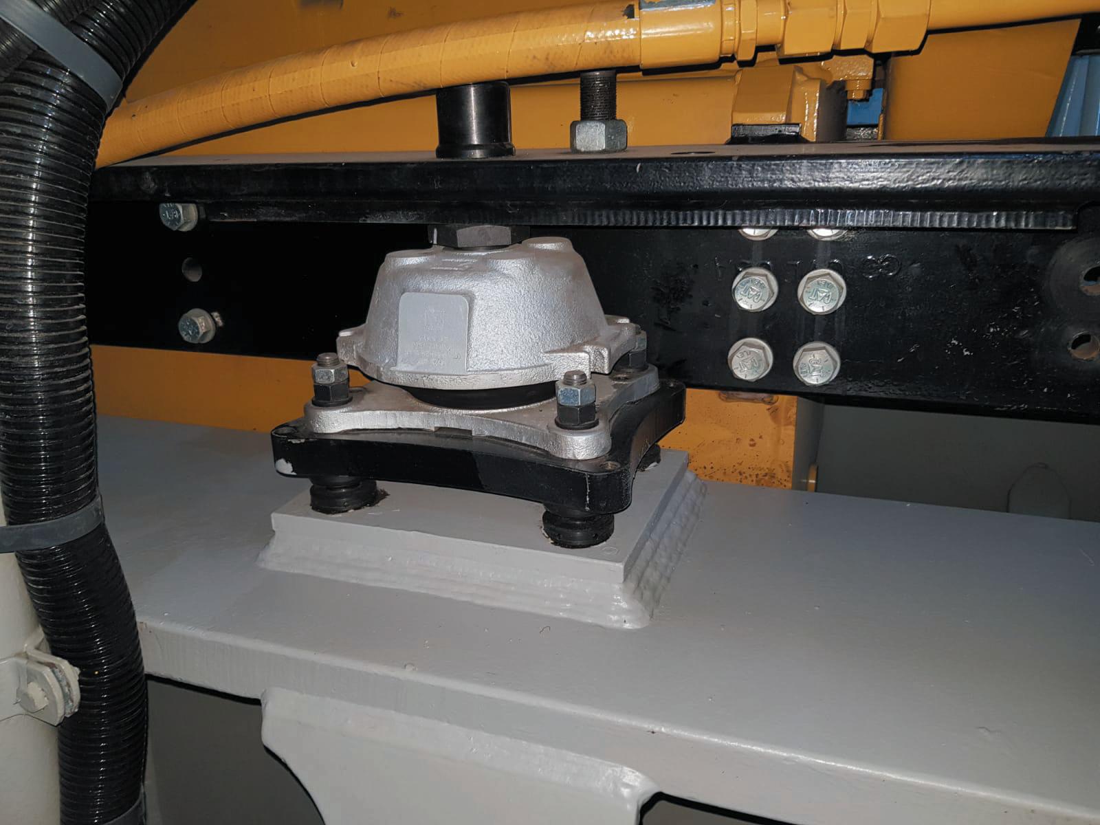
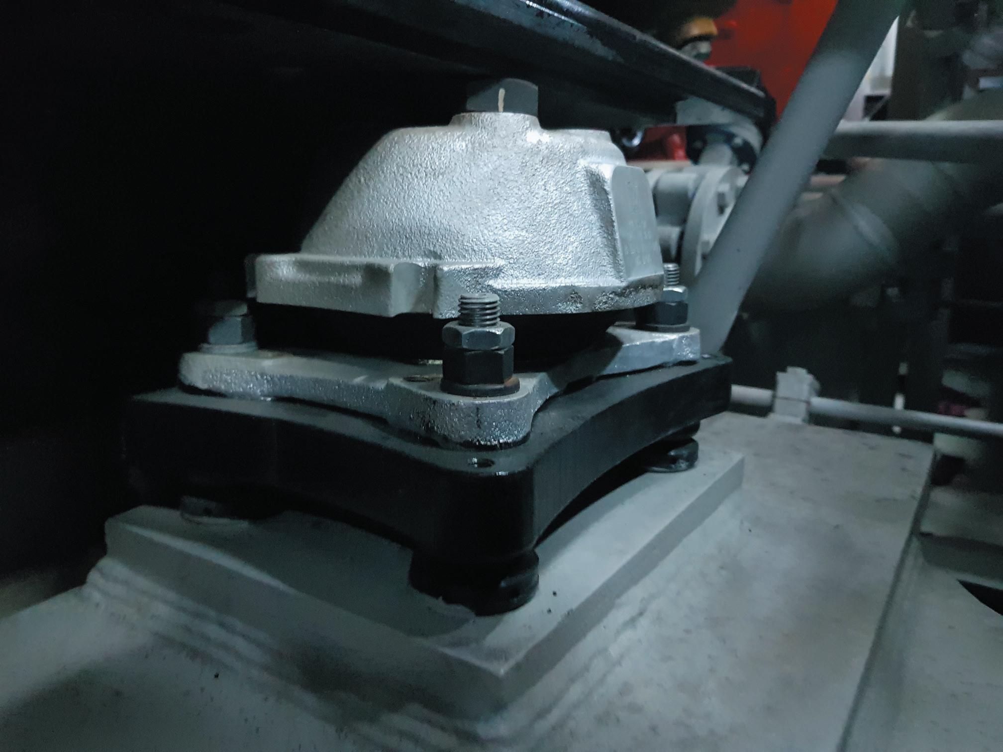
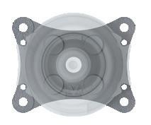
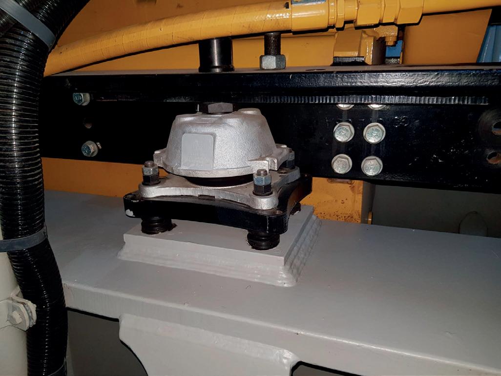
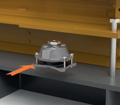
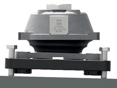
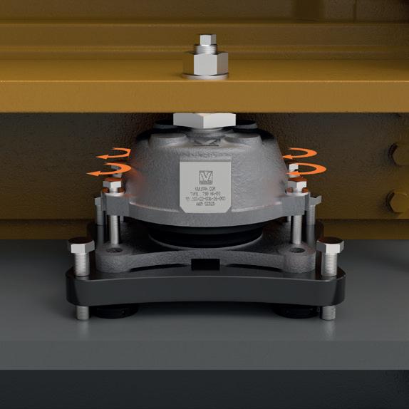
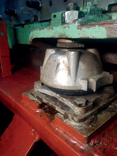
ROTACHOCK
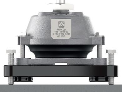
The RotaChock Mounting Plate offers an economical alternative to epoxy resin or tailor-made steel fitted blocks. First, the jacking bolts in the Mounting Plate are used to eliminate any angle between the VULKAN T-series base plate and foundation. After that, the four RotaChock at the corners are adjusted to fill the gap. The VULKAN base plate, RotaChock Mounting Plate, and machine foundation are securely tightened together with four foundation bolts.
Highly skilled craftsman are needed
Expensive equipment required for 3D machining
Blue fitting is a time-consuming process
There is no possibility to adjust after installation! Certified personnel are needed
Extensive and complex engineering
Time-consuming process and curing time
There is no possibility to adjust after installation!
No special skills or tools required
Plug and play solution, no engineering
Save time during installation
You can adjust during service life!
The selection of VULKAN T-series in combination with RotaChock Mounting Plate and it’s design option should already be made in preliminary design phase. You can download these standard design solutions in both 2D & 3D at www.rotachock. com or request them at customer service.
There are two standardized design options while using RotaChock Mounting Plates to install the VULKAN T-series.
› Option A Drilling holes through the foundation for the foundation bolts
› Option B Welding a threaded steel plate on top of the foundation
Again, this is up to the end-user to decide and should already be decided in preliminary phase. Each design options can have additional benefits when implementing the installation steps into the applications alignment procedure. Please contact the customer service to evaluate and possibly streamline your procedures together with our experienced team.
Starting in chapter 8 you can find the installation steps for Option A. The assembly manual for Option B can be downloaded at www.rotachock.com or request them at customer service. Please note that there are only minor changes in the visualization and below prescribed step 3. Both manuals are supported with installation videos that can be viewed by scanning the below QR-code or visiting the website.
In short, the installation steps for installing VULKAN T-series with RotaChock Mounting Plate are as following:
Assemble the T-mount and connect them to the unit
Preliminary alignment
Option A Drill the holes in the foundation
Option B Weld a threaded steel plate on top of the foundation
Position RotaChock Mounting Plate
Bring load into the T-mounts and wait at least 48 hours
6.2 ROTACHOCK OPTIONS
6.1 CHOCKING OPTIONS
7 DESIGN HEIGHTS
The rubber element must be aligned perfectly parallel to the machine foot to ensure optimal vibration damping and to reach its service life of 8 to 12 years. This can be monitored by checking the TB values as described in the assembly manual.
Both the T-mount and RotaChock Mounting Plate have the possibility to adjust in the parallel height. Only by adjusting the RotaChock Mounting Plate you can solve the angular gap.
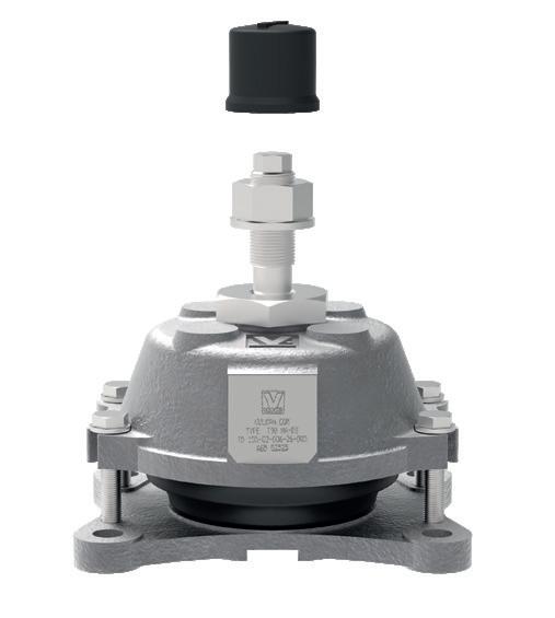
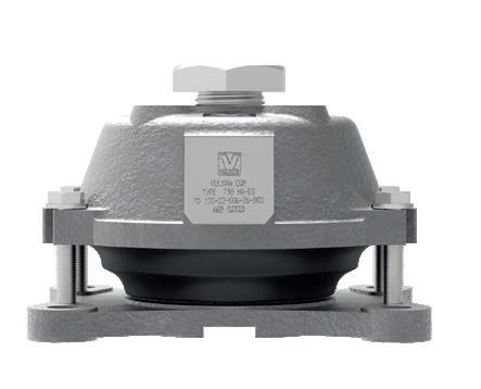
VULKAN T-SERIES
The VULKAN T-mount has an adjustment screw for parallel correction. Please check pos. 11 in the exploded drawing on page 5 for reference. In the below table 4 you can find the maximum adjustment of this screw and the resulting minimum and maximum build in height of each VULKAN T-series type. In the assembly manual, at installation step 3, we advise to adjust this screw with only 2-3 mm. We do so because the rubber elements will creep during it’s service life and you can use the maximum adjustment for corrections.
ROTACHOCK MOUNTING PLATE
While using RotaChock Mounting Plates you can correct both parallel and angular gap. Please check pos. 13, 14 & 15 in the exploded drawing on page 5 for reference. In this assembly manual we do all parallel/angular corrections by adjusting the jacking bolts (pos. 15) and fill the remaining parallel (pos. 13) and angular (pos. 14) gap with RotaChock.
Option A is preferred when there is access below the foundation for installing the foundation bolts. It’s also possible to predrill the foundation with bigger holes resulting in maximum flexibility during placement/alignment. One of the functions of the spherical spacer below the foundation is to overbridge this bigger bolt hole. Option B is preferred when there is no access below the foundation for installing the foundation bolts. It’s also possible to spotweld the welding plate on top of the foundation before the component’s placement. This still gives the possibility to move the welding plater after alignment.
8 ASSEMBLY
8.1 PREPARING RESILIENT MOUNTS FOR ASSEMBLY
PREPARING RESILIENT MOUNTS FOR ASSEMBLY
1. The connection surfaces for the mount must be free of oil, rust and contamination.
2. Ensure that the mount is properly dimensioned.
the motor per rough alignment target with appropriate hoists (e.g., hydraulic rams or jacking bolts).
8.2 ALIGNMENT ALIGNMENT - AGGREGATES
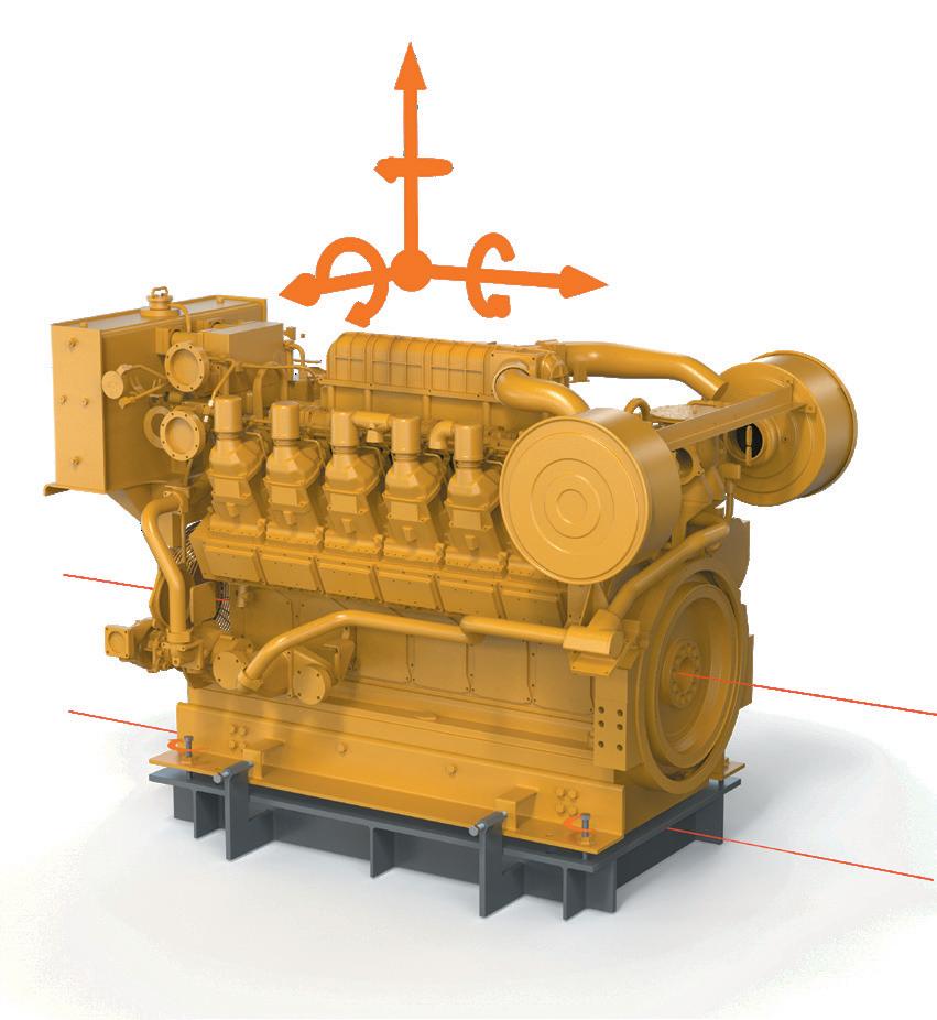
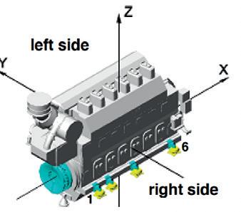
1. Before the resilient mounts can be mounted, an alignment in X,Y,Z - direction of the arrangement is required.
2. X - axis Longitudinal direction of aggregate
3. Y - axis Transversal direction of aggregate
4. Z - axis Vertical direction of aggregat
), and the upper part of the bolt (5 and keep them on hand.
Screw the upper parts of the bolt (5) in the lower part of the bolt (4) and connect the T-mounts and the motor with the fastening elements, washer (7) and nut (8) and tighten the nut hand tight (8).
The T-mounts are now hanging under the motor and are connected with the nut.
Now, the motor (driver) must be aligned to the unit (driven).
For the preliminary alignment of the unit, an allowance of 5 to 10 mm in the vertical direction (z-direction) must be taken into account relative to the driven machine.
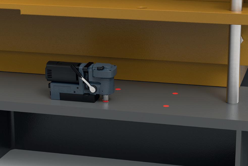
After motor alignment, while the motor is still on the jacking bolts, mark the foundation bolt holes through the T-mount bolt holes.
Remove the T-mount by removing the fastening elements, washer (7), and nut (8) and unscrewing the upper part of the bolt (5) out of the lower part of the bolt (4).
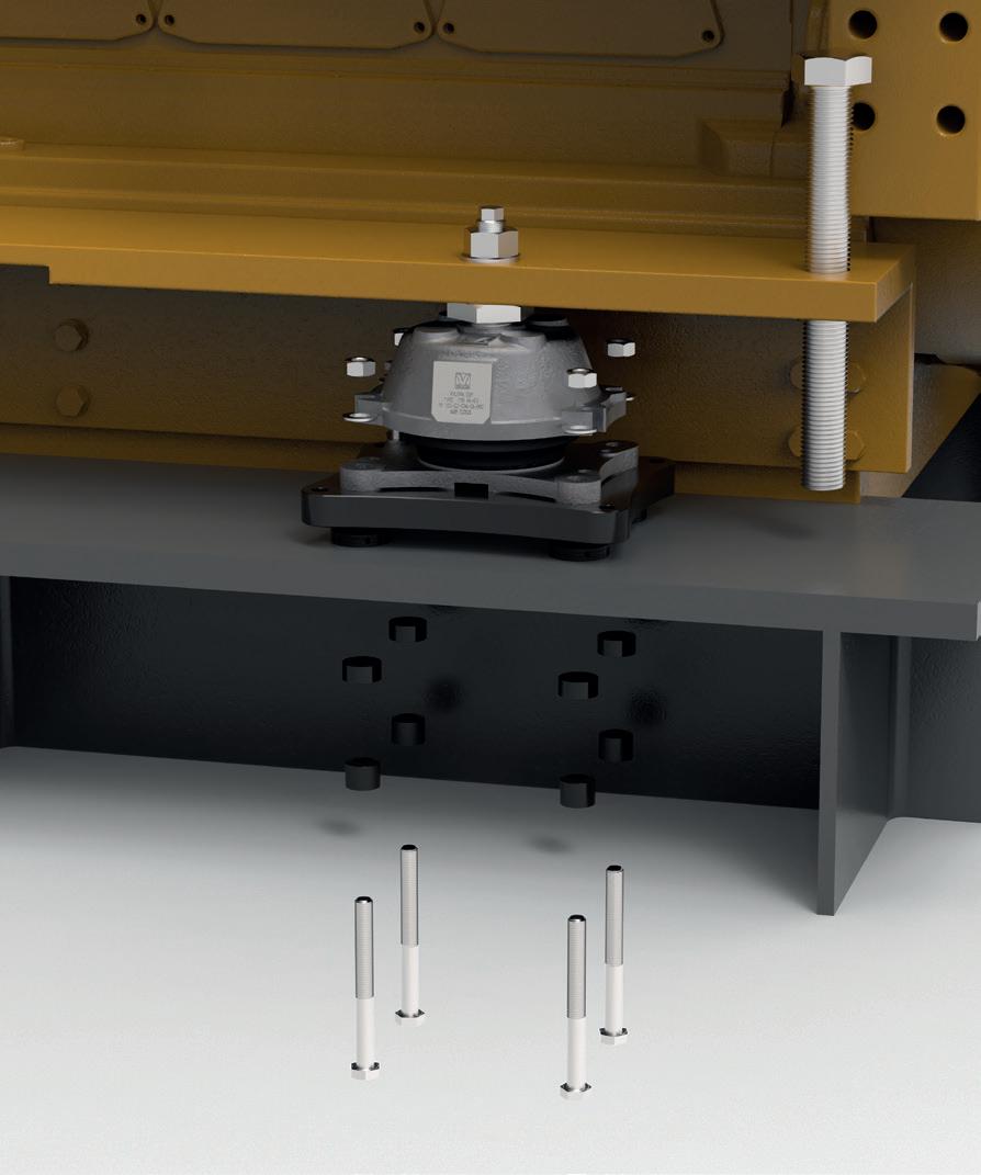
Drill the holes for the foundation bolts into the foundation.
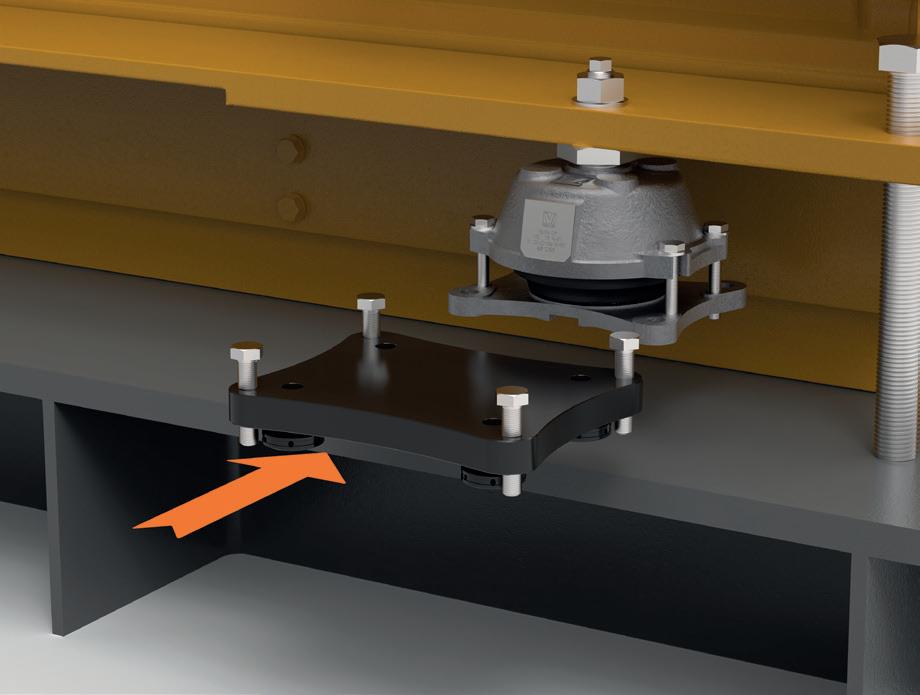
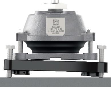
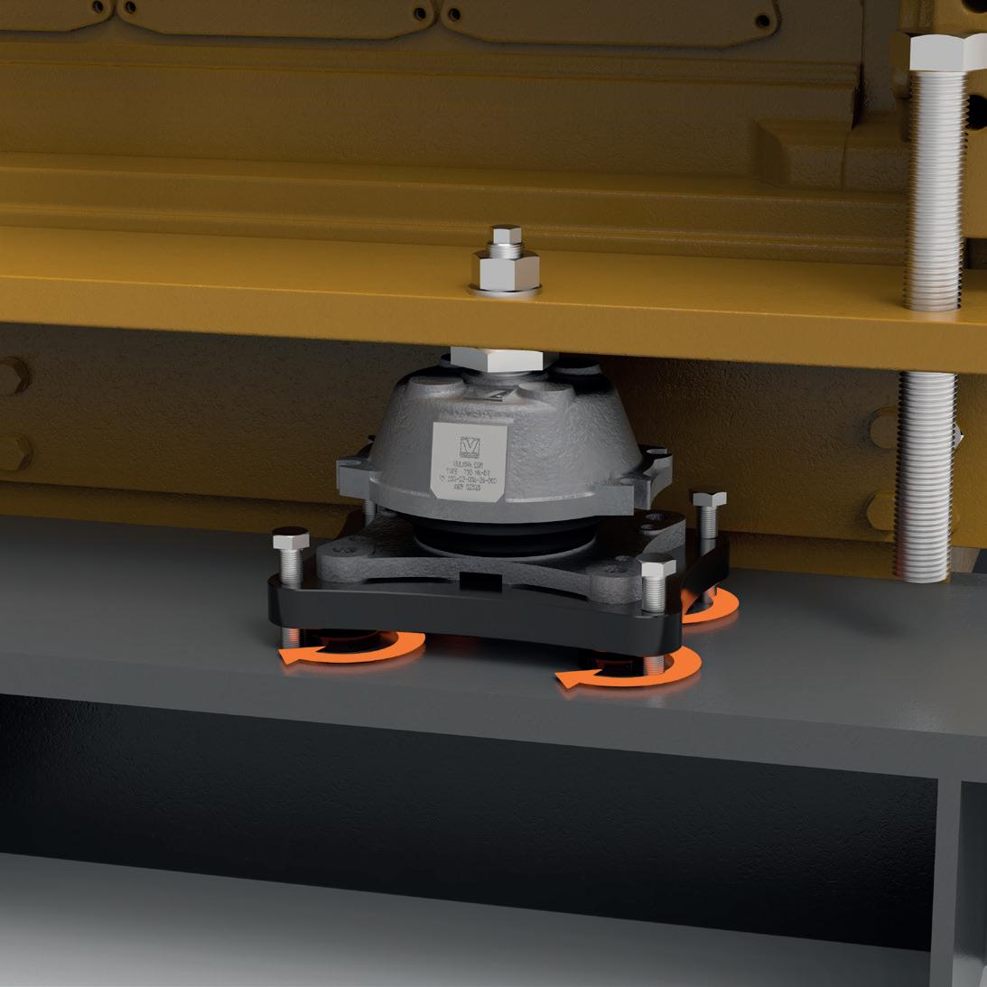
Place the RotaChock Mounting Plate between the T-mount and foundation.
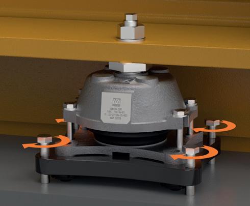
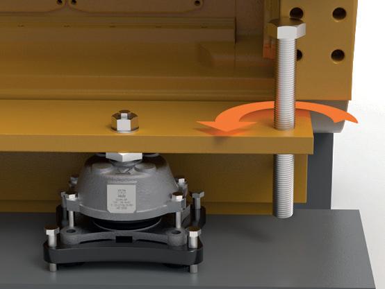
Screw down the jacking bolts in the RotaChock Mounting Plate until the top of the RotaChock Mounting Plate contacts the bottom plate of the T-mount.
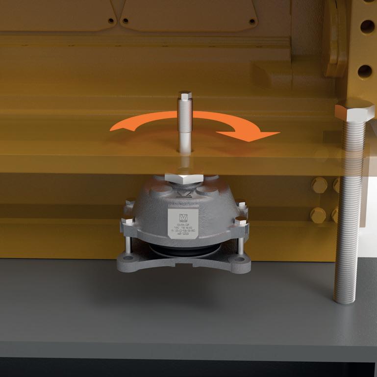
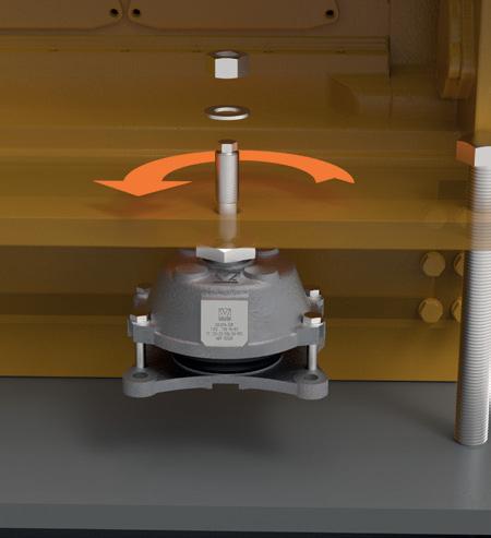
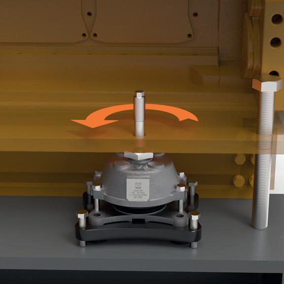
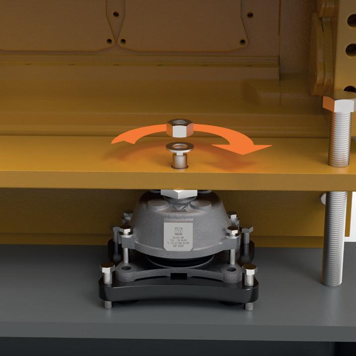
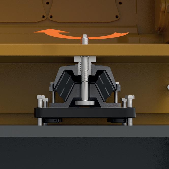
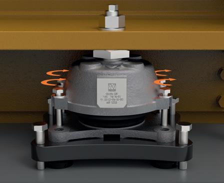
Turn the central limiter (4) + (5) counterclockwise according to below table.
Now, slowly and uniformly, bring the load onto the mounts. To do this, offload the hydraulic rams or jacking bolts of the motor.
The weights of the oil-fill quantity and waterfill quantities must be taken into account. The weights of additional fittings must be taken into account. Ensure that the applied load represents the later load in real operation.
Check limiter clearance and let the motor remain in this status for at least 48 hours; 1 week would be preferable.
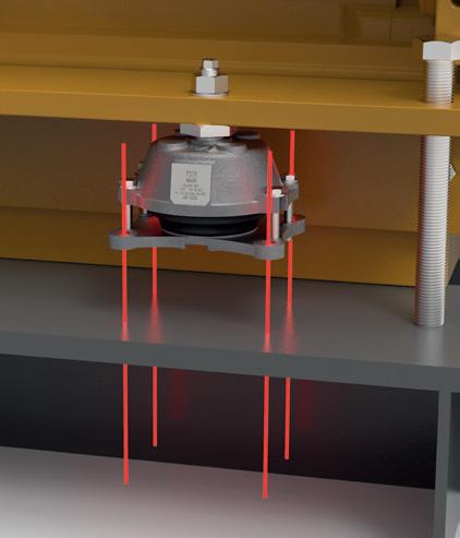
After 48 hours minimum, the load distribution over the individual T-mounts is checked via the positions TB1 to TB4.
Deviation of the averaged values (TB1, TB2, TB3, TB4 / 4) between the individual T-mounts must not exceed 3 mm. The maximum deviations within a T-mount are presented in the following table:
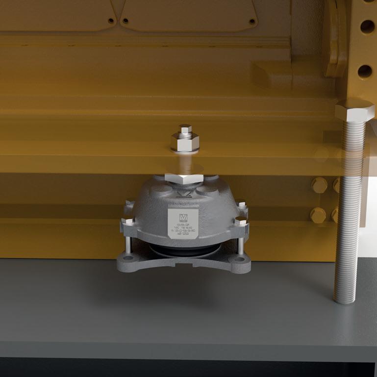
Tighten the pre-tensioning screws (6) hand tight in this position.
If the averaged deviation exceeds maximum deviation, correct with jacking bolts in RotaChock Mounting Plate
TB1
The vertical alignment of the motor can be done with the jacking bolts in the RotaChock
Plate or use motor hydraulics/ jacking bolts.
Mounting
Mounting Plate.
There should be no gap between the RotaChock Mounting Plate and bottom plate of the T-mount after alignment.
Unscrew and remove the pre-tensioning screws (6).
Enter the TB values in the attached measurement sheet on page 28
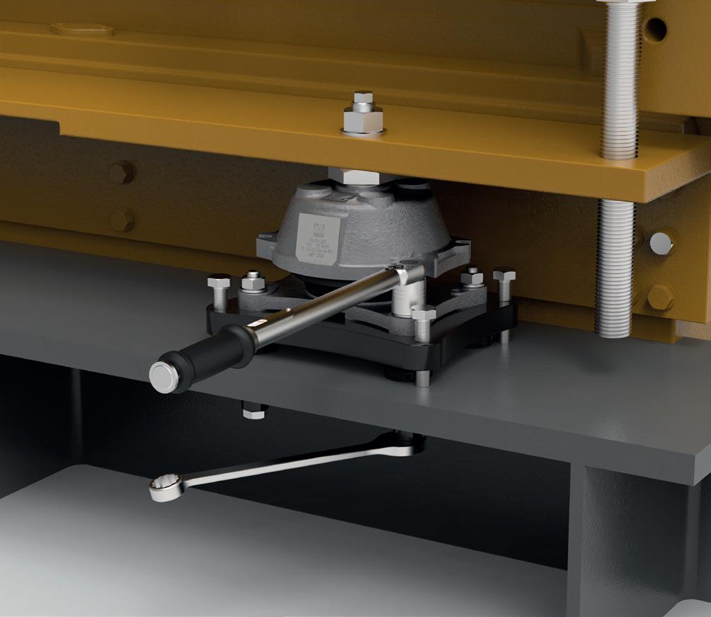
Mount the foundation bolt through the T-mount, the RotaChock Mounting Plate, and the foundation top plate, and torque.
The dimensions, screw qualities, and tightening torques are provided in the attached table.
The table values are reference values. The final values are determined by the application. Table 11
If the averaged deviation exceeds maximum deviation, correct by reinstalling jacking bolts (15) in RotaChock Mounting Plate or adjusting the 4 RotaChock Center Rings (13) in the Mounting Plate.
9 SERVICE LIFE
9.1 MAINTENANCE
The maintenance tasks that are required for optimal and trouble-free operation are described in this chapter. Under normal work conditions and with professional configuration of the mounts system, the rubber element has a realistic service life of 8 to 12 years. The actual service life is naturally influenced by the (dynamic) loads and the ambient conditions.
The max. working elasticity at nominal load, creep behavior and thermal load that the mount arrangement can still tolerate is specified in the table below, for each type and each composite individually. The values specified below must be measured at a rubber temperature of 20°C.
9.2 CLEANING THE INSTALLATION
The environmental influence on the wear can be minimised through visual inspection of the rubber element, in this process look for oil contamination and damage! Oil residues must be removed with an off-the-shelf, mild household cleaner. The rubber element should be cleaned as specified in DIN 7716, to ensure the optimal service life.
Do not – under any circumstances – clean the rubber element with solvents! If the surroundings of the rubber element are cleaned with these types of aggressive agents, the surroundings must then be re-cleaned again with a mild household cleaner.
Table 14
9.3 CHECKING THE INSTALLATION
Over time, the function of the T-mounts in implementation is influenced by various environmental conditions. If the assembly is executed as specified in this installation manual, only a periodic check is necessary, which must be logged.
Check criteria:
1 Identification number of the mounts
2 Temperatures of the mounts in implementation
3 Cleanliness of rubber surface (page 26)
4 Load distribution over the mounts (TB) (step 21 on page 18)
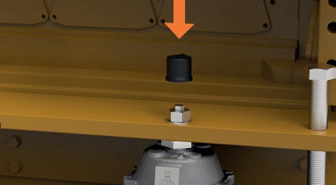
5 Play of the central limiter (step 31 on page 23)
6 Height of the height adjustment nut (step 3 on page 12)
7 Height of the adjustment of RotaChock (page 9)
Deviation of the averaged values (TB1, TB2,TB3, TB4 / 4) between the individual T-mounts must not exceed 3 mm. The maximum deviations 10 on
9.4 SHEET OF MEASUREMENT
Measurement ID:
Date:
Type of mount:
Amount of mounts installed:
Running hours:
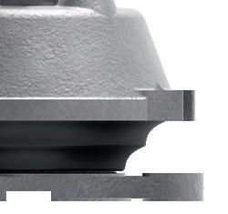
a Insert a feeler gauge through the slot of the base casting.
b Increase the thikness of the feeler gauge stepwise about 0,5mm to determine the measure (min. 2mm - warm condition)
9.5 ALIGNMENT AND CORRECTION
The rubber element must be aligned perfectly parallel to the machine foot to ensure optimal vibration damping and to reach its service life of 8 to 12 years. This can be monitored by checking the TB values as described in step 9.3 on page 27
VULKAN T-MOUNT
The VULKAN T-mount has an adjustment screw for height correction. Please check pos. 11 in the exploded drawing on page 5 for reference. In table 4 on page 9 you can find the maximum adjustment of this screw and the resulting minimum and maximum build-in height of each VULKAN T-series type.
In the assembly manual, at installation step 3, we advise adjusting this screw with only 2-3 mm. We do so because the rubber elements will creep during its service life, and you can use the maximum adjustment for corrections.
ROTACHOCK MOUNTING PLATE
While using RotaChock Mounting Plates you can correct both parallel and angular gap. Please check pos. 13, 14 & 15 in the exploded drawing on page 5 for reference. In this assembly manual, we do all parallel/angular corrections by adjusting the jacking bolt.
As described in paragraph 7 -Design heights, both the T-mount and RotaChock Mounting Plate have the possibility to adjust in the parallel height. Only by adjusting the RotaChock Mounting Plate, can you solve the angular gap and correct TB values within limits.
The rubber elements will creep during service life, and you need to check two alignment values.
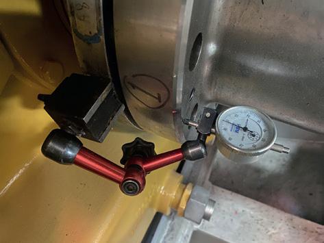
1. SHAFT / COUPLING ALIGNMENT
Due to creep, the centerline between components or alignment target will offset in time, and you need to correct it. You can do so by rotating the adjustment screw (pos. 11). Remember that the maximum allowed distance mentioned in table 4 on page 9 must not be exceeded.
When realignment needs to be done and results in an out-of-range height of the adjustment screw, the first correction of 3 – 5 millimeters can be done with the RotaChock Mounting plate by adjustment as described on the right.
2. TB VALUES
When TB values are outside their recommended values; you can correct them by following steps:
1 Loosen foundation bolts reverse step 29
2 Reinstall jacking bolts in the mounting plate
Correct TB values by adjusting jacking bolts
When corrected; fill the gap with RotaChock see step 27 see step 29
10.1 DISMANTLING
Before dismantling, make sure that the machinery equipment is fixed and unable to move.
1 Assemble the pre-tensioning screws (6) and lock the mount height.
2 Remove the cap (9), the nut (8) and the washer (7) and keep them on hand.
3 Turn the central limiter (4 + (5) counter clockwise, until the bolt rests on top of the base casting (1).
4 Unload the mounts slowly and evenly 2-5 mm using a hydraulic piston.
5 Remove the upper bolt (5).
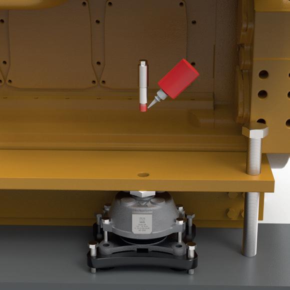
The upper bolt is fixed with Loctite to the lower part. We suggest heating the upper bolt to 100° C to soften the Loctite for easy disassembly.
6 Unscrew and remove the screws from the base casting (1).
7 Remove the mount.
10.2
DISPOSAL
If a return or disposal agreement has not been concluded, then recycle dismantled components:
› Dispose of rubber mixtures in accordance with governmental guidelines.
› Sort and dispose of remaining components in accordance with national regulations and with material condition.
› Remove fuels and auxiliary materials, as well as residual processing materials and dispose of these items in an environmentally responsible manner.
10 AFTER LIFE
10.3 REPLACEMENT
The system needs to be replaced when the maximum allowed adjustment is reached. First, you replace and dispose of the mount per the given instructions. Then, when RotaChock Mounting Plates are used, you can build back on the same system. This is thanks to the unique readjustment capability of RotaChock. When other chocking systems like steel fitted blocks or epoxy resins are used, these need to be replaced entirely. You must start again from scratch; otherwise, it will be impossible to correct the new TB values, and the resilient system won’t function properly.
Life-threatening danger due to incorrect dismantling! Incorrect dismantling can cause lifethreatening situations. Therefore:
• Strictly follow the dismantling sequence specified here.
Our global covering service network can assist with this servicing. Our global network ensures access to a whole support team, from design engineers at the knowledge centers to service engineers in the field. With his local presence, we offer fast response time and the availability of experienced engineers. We have the expertise and equipment to assist you with a quick and trouble-free replacement.