NANSIG SpinalSurgery Workshop Booklet


Tableof Contents
Authors: Rishabh Suvarna, Aalia Shajani, Joecelyn Kirani Tan
Editors: Saima Ahmed, Marwan Al-Munaer, Ashviniy Thalmimaran, Rishabh Suvarna
WelcomeMessage
Cervical&LumbarDecompression
TransforaminalInterbodyFusion
PosteriorInterbodyFusion
PedicleScrewFixation
Discectomy
Kyphoplasty&Vertebroplasty
Page 3
Pages 4-6
Page 7
Pages 8-9
Pages 10-11
Page 12
Pages 13-15
Welcome Message

A heartfelt welcome to the first NANSIG spinal workshop. It is with great pride and honour that we convene here in Glasgow, under the esteemed guidance of Mr. Mathieson, in a city renowned for its leading neurosurgical centre. Today’s workshop marks a departure from conventional NANSIG neurosurgical workshops by fully focusing in on the spinal perspective of neurosurgery, which is a foundational element of the specialty. This tailored workshop is aimed to equip delegates with both the theoretical foundations and practical skills necessary for mastering common spinal procedures. It will also be shedding light into the crucial skill of achieving intraoperative haemostasis. Your dedication for learning and spirited participation empower us at NANSIG to continue forging new paths in neurosurgical education and inspire us to broaden our reach to foster opportunities for brain and spine enthusiasts throughout the UK We trust that you will find this workshop to be an enriching experience, and hope that you utilise this opportunity to deepen your knowledge, connect with peers, and further ignite your passion for the path you are pursuing Always remember to enjoy the journey and the connections you make along the way
MarwanAl-Munaer NANSIGViceChairofEducation
I am honoured and delighted to welcome all attendees to the first-ever NANSIG Spinal Surgery Workshop hosted in Scotland. This workshop is a significant milestone in the pursuit of advancing spinal surgery education and training, and it is my privilege to lead this collective effort. Scotland's esteemed academic institutions and healthcare facilities, combined with its rich history, offer an ideal setting for fostering intellectual discourse and practical learning experiences. This workshop presents an invaluable opportunity for aspiring neurosurgeons to engage in comprehensive discussions, gain practical insights, and refine their skills under the guidance of experts in the field. Our objective is to offer participants a transformative educational experience that will equip them to excel in their future endeavours in neurosurgery. I encourage each attendee to approach this workshop with intellectual curiosity, determination, and scholarly rigour. May this workshop serve as a catalyst for inspiring excellence in spinal neurosurgery, both now and in the years to come
SaimaAhmed
NANSIGWorkshopLead
3
CERVICAL DECOMPRESSION

Indications
Radiculopathyormyelopathycausedbyeitheroneortwo levelsofanteriorcervicalcompression
Posterolateral soft disc herniations, foramina stenosis, or bonespur
Spinal canal due to ligament flavum hypertrophy or ossification,facetjointcyst,andligamentflavourcyst Patientspresentingwithacompressivelesioncausingarm weakness, paraesthesia and unremitting radicular pain withorwithoutlowerextremityhyperactivereflexes
Steps
Contraindications
Segmental instability, kyphotic deformity, multiple-level pathology.
Associated infection, tumour, and fracture in the region of thecervicalsegment.
Patients with myelopathy caused by anterior disc herniationand/orcalcification
1 AnaesthesiaandSkinIncision:General anaesthesiaisadministered,andthepatientis positionedproneonaradiolucenttablewiththe cervicalspinedelordosated Asmallskinincisionis madeverticallytowardsthe"V"pointofthefacet joint
3.
PreoperativePreparation:Imagingstudies includinganteroposterior,lateral,and flexion/extensionimagingofthecervicalspine,MRI, andCTscanareperformedtoassessthecondition andplanthesurgery
2 InsertionofEndoscope:Aworkingchannel, endoscope,andinstrumentsareplacedoverthe facetjointthroughtheskinincisionusingadilator Thenavigationsystemassistsintheplacement
4.
SurgicalProcedure:Softtissueiscleanedusing bipolarradiofrequencyandforceps Themarginsof thesuperiorandinferiorlaminaandV-pointare identified Keyholeforaminotomyisperformed usingadiamondburrtoremovethecephalic laminaanddecompressthenerveroot Ligamentumflavumisresected,andherniated fragmentsareremoved
5.
FinalCheckingPoint:Nerverootsandspinalcord aredecompressed,andfurtherdiscectomyor osteophyteresectionisperformedifnecessary The incisionisclosedwithouttheneedforadrain
Benefits
Reduced blood loss, muscle disruption, and bony removal, results in faster recovery and fewer postoperative complications
Lower risk of injury to oesophagus and laryngeal nerve comparedtoACDF
Motionpreservation
Minimallyinvasiveapproachresultsinmorerapidfunctional recovery,shorterinpatientstays,andearlierreturntowork
Endoscopic technique provides magnified view and limited bleedingundercoldlightandcontinuousirrigationsystems, enhancingsurgicalprecisionandreducecompliactionrisk
Better postoperative stability compared to open ACDF, particularlyduringrearprotrationandlateralflexion
Limitations
Steeplearningcurveandhighriskofspinalcordinjury. The initial cases may require longer operative times, contributing to a longer learning curve However, proficiency can be expected after approximately 22 cases
Endoscopehasanarrowsurgicalfield
Anatomical variability among individuals and the variability in the position setting of patients can make it challengingtoaccuratelyassessthekeyholesizearound theV-point
Risk of complications (although low): transient hypesthesia,woundcomplications
4
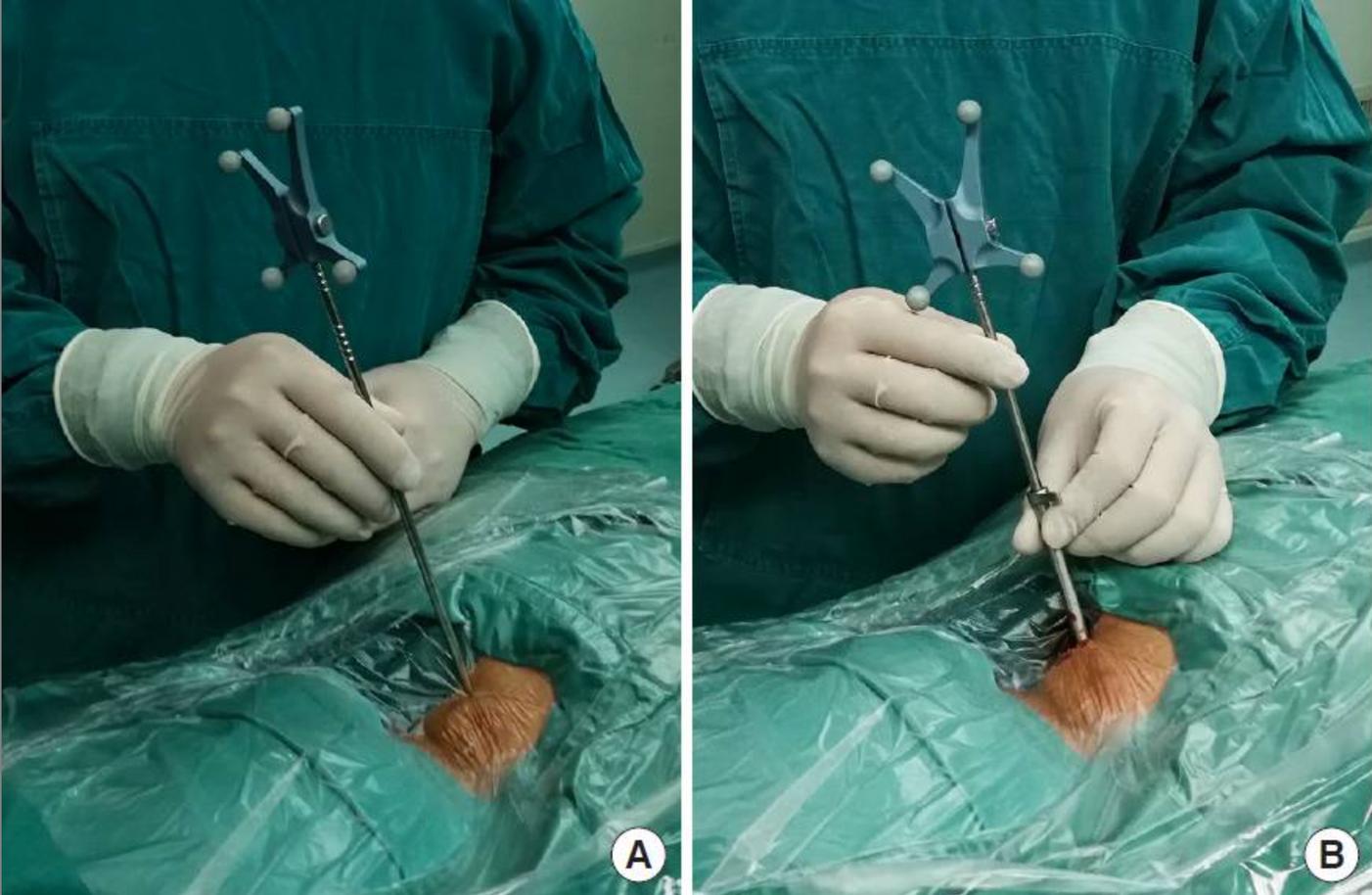
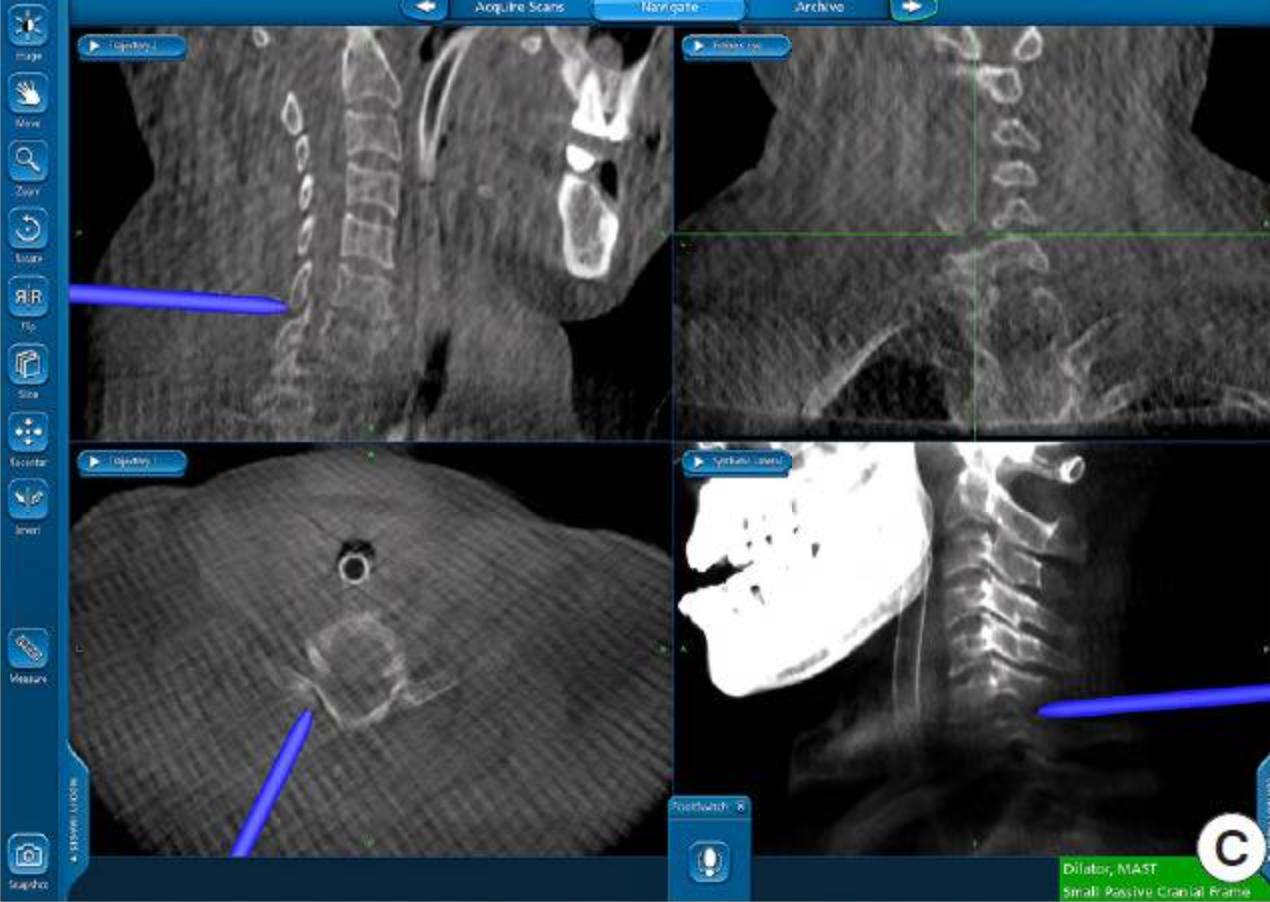
A B C
Figure 1: Illustrations of Cervical Decompression Procedure. Setting up the working tube and navigation: (A) The incision location was identified using a 3-dimensional navigation system (B) A 75-mm working tube was placed through the navigation probe,servingasabluntdilator (C)Thecorrectpositioningofthe workingtubewasconfirmedusingthenavigationsystem
LUMBAR DECOMPRESSION
Indications
Lumbar spinal stenosis, characterised by neurogenic claudication,foraminastenosisandlumbardischerniation.
Lateral stenosis with lateral recess height less than 2mm, depthlessthan2-3mm.
Ligamentum flavum hypertrophy (LFH) as the cause of stenosis(formildprocedure)
Symptomsstemmingfrommechanicalbackpainassociated withone-ortwo-leveldiscogenicissues
Steps
1
PreoperativeEvaluation:Carefulreviewofcross-sectional images(MRIorCT)toassesstheavailableepiduralspace, thicknessoftheligamentumflavum(LF),andpotential mechanicalimpedimentstoinstrumententry
2
Contraindications
Absolutecontraindications:
Priorspinesurgeryorinfectionpresenceattargetlevel
Relativecontraindications:
PresenceofhigherthangradeIIspondylolisthesis
Presenceofbleeding/diathesis/coagulationdisorder
Presenceofsystemicinfection
PatientPositioning:Placethepatientinapronepositionwith abolsterorpositioningaidtoreducelumbarlordosisatthe indexlevel,facilitatingtheentryoftheworkinginstruments.
EstablishSafetyBarrier:Useanepidurogramorbony landmarkstoguidetheprocedureandestablishaworking safetybarrier.
4.
3 FluoroscopicImaging:Obtainbaselinepreoperativeimages inallviews,includingthecontralateralobliqueview,to establishthefluoroscopicanglefortheprocedure
Arecommendedimaging techniqueforassessing theinterlaminarspace involvesobtainingan anteroposterior(AP) imagewherethe vertebralendplatesare squaredwiththe fluoroscopicbeam.
6.
5 Trocar/CannulaPlacement:Advancethemild trocar/cannulaalongthetrack,restingitontheinferior lamina Confirmplacementusingfluoroscopicimaging
7
AnaesthesiaandTrackInsertion:Usinglocalanaesthesia, insertaspinalneedleonthelamina,aligningitwiththe sagittalpitchoftheindexlaminaandlateraledgeofthe spinousprocessoftheinferiorlamina Anaesthetisethetrack andtreatmentarea
PortalStabilisation:Placeamildportalstabiliseronthe patienttopreventmigrationofoperatingdeviceswhile allowingformovementtosculpttheinterlaminarspace
Themildportalstabiliserpreventsthedownward movementoftheoperatingdeviceswhileenabling bothupwardanddownwardmotiontoshapethe interlaminarspace
8 LFDebulking:Useatissuesculptortoremovesmallsections ofLF,typicallyrequiringthreesetsofthreepassesforproper debulking Continueuntilthereisnolongermaterialto debulkandtheinstrument"fallsinthechannel"createdby decompression
10.
BoneRemoval:Useabonerongeurtoremovebiopsy-sized bonefragments,wideningtheinterlaminarspacetoallow furtheradvancementofthemildcannula.Continueselective removalofsmallamountsoflaminauntilinterlaminar accessisachieved
9 ProcedureCompletion:Performtheprocedureonthe oppositesideandotherlevelsifnecessary Oncecompleted, patientstypicallyresumenormalactivitywithin24hourswith norestrictionsandbeginprescribedphysicaltherapyat2 weekspost-procedure.
Benefits
Broad patient selection: suitable for neurogenic claudication with ligamentumflavumhypertrophy(ofmorethanorequalto25mm),evenin patients with comorbidities (No contraindications for patients with osteoporosis)
Lowestcomplicationrateandreoperationratesforlumbarspinalstenosis
Clinically significant long-term improvement in mobility and pain reduction Minimallyinvasivewithintactspinalanatomyandminimaltissuetrauma No implants are required; Steroid-free procedure, reducing immunosuppressionrisk.
Shortornohospitalstay,withresumptionofnormalactivitywithin24hwith norestrictions
Limitations
Risk of complication: Dysesthesia, untreated pain, dural tear, disc herniation, infection, incomplete decompression, epidural haematoma,andmotorweakness
Treats stenosis secondary to ligamentum flavumhypertrophyonly
Contraindicatedatthesiteofprevioussurgery
Someradiationexposuremayoccur
5 A B C
Figure 2: Illustrations of Lumbar Decompression Procedure. A) imaging technique for assessing the interlaminar space, B) Mild portal stabiliser for navigationintointerlaminarspaceandC)Bonerongeur andSculptor
PLAN YOUR DECOMPRESSIVE APPROACHES
6
TRANSFORAMINAL LUMBAR INTERBODY FUSION
Steps
Positioning:
1 aProne,supportareaspadded
b
. Withfusionhip:extendhipsforincreased lordosis
2 WiltseApproach:
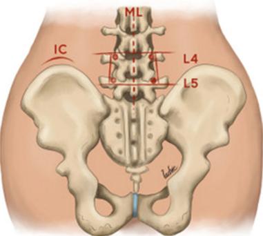
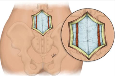
Incision: Posterior midline incision for subperiosteal exposure of spinous process, laminea, facets, transverse process (Figure 2a,2b)
3 aBilateralincisions(4.5cmfrommidline)
b.
c
. To access lower lumbar and sacral vertebrae
Landmark: natural cleavage plane (multifidus part of sacrospinalis and logissimus),bluntdissection
Indications
Alldegenerativepathologies
Broad-baseddiscprolapses, degeneratediscdisease, recurrentdischerniation Pseudoarthrosis
Symptomaticspondylosis
AnatomicalConsiderations
Contraindications
Extensiveepiduralscarring Arachnoiditis
Conjoinednerveroots (preventingaccesstodisc space)
Osteoporoticpatients
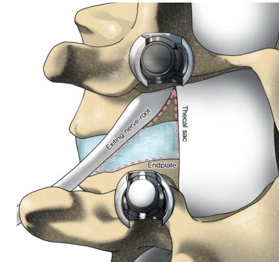
Kambin’sTriangle:Transforaminalcorridortointervertebraldisc (Figure1)
Medialborder:traversingnerveroot,thecalsac
Anteriorborder:exitingnerveroot
Inferiorborder:endplateofcaudalvertebrae
Accessusingaminimallyinvasivesurgicalapporachwith magnificationcanreducemuscleinjury,minimizebleeding
4
5.
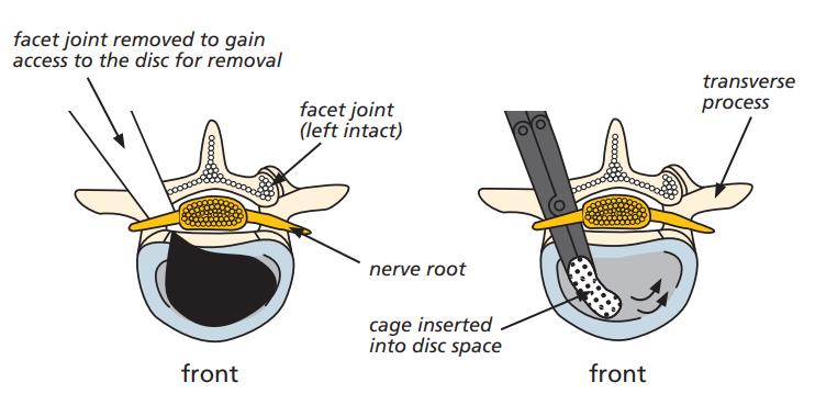
Identification of Pars interarticularis and resectedtoaccessintervertebralspace
Facetectomy of superior and inferior facets to be fused; provides access to kambin’s triangle
6
7.
Discectomy performed following retraction oftraversingnerverootmedially.
Endplate preparation and Intervertebral cage with morselized autologous or allogenic bone graft is placed within disc space
8.
PediclescrewsplacedbeforeorafterTLIF
Benefits
360degreesfusion;lateralitymeanslessretractionon neuralelements
Easieraccesstoposteriorstructures
Preservationofligamentousstructuresrequiredfor biomechanicalstability
Safelyconductedevenatupperlumbarsegments Lowerdurotomyrisk(comparedtoPLIF)
Lessdamageonposteriorligamentouscomplex, preservesbiomechanicalstability
TLIFusefulinrevisioncases
Reducedbloodloss,muscleinjury,earlyrecovery
Limitations
Considerableparaspinalmuscleinjurywithprolongedmuscle retraction
Impossibletocompletelyremovealldiscmaterial
SimilartoPLIF,associatedwithsignificantparaspinaliatrogenic injurywithprolongedmuscleretraction
Difficultendplatepreparationcomparedtoanteriorapproaches Difficulttocorrectcoronalimbalanceandlordosiswiththis technique
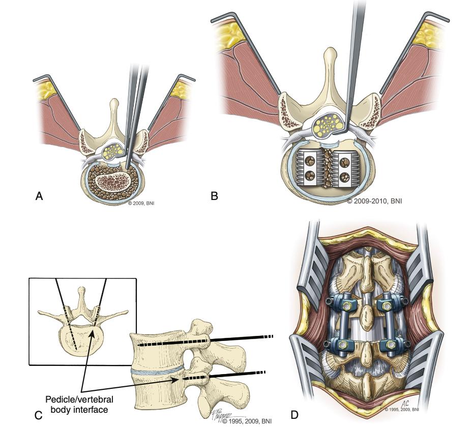
Figure 3: Kambin’s Triangle to expose intervertebral discforTransforaminalLumbarInterbodyFusion
7 A C B
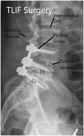
Figure4:IllustrationsofTLIFProcedure.A)IncisionviaWiltse’sApproach, B)facetectomyandEndplatepreparation,C)Postoperativeresult
POSTERIOR LUMBAR INTERBODY FUSION (PLIF)
Indications
severelowerbackpaincombinedwithneurologicalsymptomsof legpainthatpersistdespitenonsurgicaltreatmentsuchconditions include:
recurrentdischerniation spondylolisthesis bilateralmidlinedischerniation segmentalinstability degenerativediskdisease psuedoarthrosisduetofailedfusionfrompreviousspinalfusion surgery
OPEN POSTERIOR LUMBAR INTERBODY FUSION
Steps
1
Positioning:(a)Prone,(b) onaJacksontable
2
3.
OperativeLevelIdentification:using fluoroscopy
Incision:Posteriormidlineincisionforexposure ofanatomy(spinousprocess,lamina,facets, transverseprocess)
4.
Dissectionandexposure: (a)subcutaneous tissuedissected,(b)thoracolumbarfascia incised,(c)paraspinalmusclesdetached subperiosteallyfromspinousprocessand lamina,(d)facetsand transverseprocesses exposed(andserveasvitallandmarksfor fusion),(e)ligamentumflavumcompletely removedforeachtreatedlevel
5.
Creationofawidewindow: medialtwothirdsof superiorfacetandloweronethirdofinferior facetjointsareresectedtocreateawide windowandthuspreventingexcessivetraction onthespinalcordduringplacementofinter bodygraft
Contraindications
notrecommendedinpatientswithextensiveepidural scarring activeinfection arachnoiditis
AnatomicalLandmarkstolookoutfor Spinousprocesses illiaccrest posteriorsuperiorilliacspine(PSIS)
6 Discectomyperformed
Retraction:ofduralsacandnerverootmedially, formaximalexposureofinterbodyspace
7
8.
EndplatepreparationandIntervertebralcage: underdirectobservationofcranialandcaudal nerveroots,abonegraftspacerorcageis placedintotheinterbodyspace
9.
10
Bonegraftpackingisthenperformedto augmentfusion
Stabilisationwithinternalfixationusing screws/rodsoralternatively,plateconstruct,to aidinarthrodesis
Additionalpoints
Bone graft of choice is surgeon dependent Options include; threaded cages, titanium mesh cages, auto- and allograft +/- use of bonemorphogenicproteinBMP)
Newly introduced expandable inter body spacers; advantages - allow for insertion through a smaller corridor (less soft tissue dissection,boneremovalandneuralretraction),expandablefeatureusedtoincreaselumbarlordosisandreinstateforaminalheight
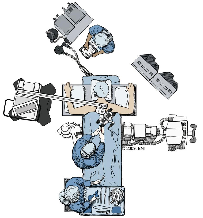
Figure5:IllustrationsofopenPLIFProcedure.A)Operatingtheatrewith patient lying prone, microscope and fluoroscope in place, B) midline incision over thoracolumbar spine, C) retraction of nerve roots, bilateral insertionofinterbodydevices,discspacedistractedusingpediclescrew, finalarthrodesisreinforcedwithscrew/rodconstruct,D)finalresult
D 8 C A B
POSTERIOR LUMBAR INTERBODY FUSION (PLIF)
MINIMALY INVASIVE POSTERIOR LUMBAR INTERBODY FUSION
Steps
Typically utilises endoscopic and microscopic tubular dilators,retractors,bed-mountedflexiblearm
1
2
Positioning:(a)Prone,(b) onaJacksontable
Operative Level Identification: following identification, a 2-4cm midline incision is made and a Steinmann pin is passed until the medial borderofthefacetjointisreached
3
Extension of incision: the skin incision is then extended 2-3cm above and below the Steinmann pin.
4
Visualisation: serial dilators are used to split muscle layers Once muscle layers are split and visualisation is sufficiently achieved, the final channelisfixedtotheflexiblearmretractor,which is mounted to the table side rail subsequently, dilatorsareremoved
5
Exposure, laminotomy, removal of ligamentum flavumperformed.
6 Interbodygraftispositionedintodiscspace
Distraction:small interbody distractor devices are insertedintothediscspaceandrotatedtodistract the disc space and restore intervertebral height Distractionofthecontralateralsideissubsequently performedinasimilarfashion
7
8
Bone graft is then packed anteriorly in the disc space and additionally packed around and within theremainingfacet
Whatthefutureholds
Spinalnavigationandsurgicalrobotics

Eg A dynamic reference frame fixed on the PSIS and 3D reconstructed images are created using intraoperative CT, connected to navigations A planar probe identifies the best entry point and trajectory Numerous stab incisions can be made or alternatively, a long paramedianincisioncanbeused Oncethenavigatedguideddrillisinplace,acannulaandhighspeeddrillareusedtocreateapathfor instrumentation.
Additionalpoints
APandlateralfluoroscopyhavebeenhistoricallyusedtovisualisethepedicle
Typically,ajamshidineedleisusedtopenetratethedorsolumbarfasciauntilthepedicleisreached
Theneedleisslowlyadvancedthroughthepediclespasttheposteriormarginofthevertebralbody.
Theobturatoristhenremovedfollowingconfirmationofthelocationoftheneedleintheposteriorpartofthecentrum,andalongKwireisexchangedthroughit ThisisdoneusingtheSeldingertechnique
The screw path is then defined using the sequential dilators and multiaxial pedicle screws are attached to the screw extender sleevesandpassedovertheK-wire pre-contouredrodsarematedontothescrewswhicharethensecuredinplaceusinglockingboltsonthescrews
Benefits
Possibletobeminimallyinvasive,withusing3Dnavigation androboticassistance(usefulincomplexcases,reduces radiationexposureandprovidesimprovedaccuracywith reducedoperationtime)
Roboticassistancecanalsofurtherimproveaccuracy, minimisetheneedforfluroscopyandisfavourableinpatients withunusualanatomicallandmarks
Theuseofexpandableinterbodyspacers,3D navigation/imageguidanceaswellasspinalroboticshave recentlyrevolutionisedtheprocedure evenloadsharingongraftandimprovedfusion/graft constructbloodsupply.
restoresinterbodydistanceandmaintainssegmentallordosis atthelevelwhichhasbeenfused decompressionofnerverootsandneuralforamina
Limitations
significantparaspinalmuscleinjurywithprolongedmuscle retraction
paraspinaliatrogenicinjuryasaresultofprolongedmuscle retraction considerabletractiononthecalsacandnerveroots associatedwithincreasedriskofnerverootinjuriesand incidentaldurotomy
Whenbeinginserted,theInterbodygraftisusuallyclosetothe nerverootthatexitsatthelevelabovethediskspace,which increasestheriskofnerverootinjuries adjacentleveldisease psuedoarthrosisincasesofinstrumentationwithPLIF graftretropulsion(rateofincidencedecreaseswithsurgeon experience)
Figure 6: Illustration of Minimally Invasive PLIF A) Entry points, B) dilatorsusedinmusclesplittingtechnique
9
A B
PEDICLE SCREW FIXATION
AnatomicalConsiderations
Entrypointsvarybasedonlocation
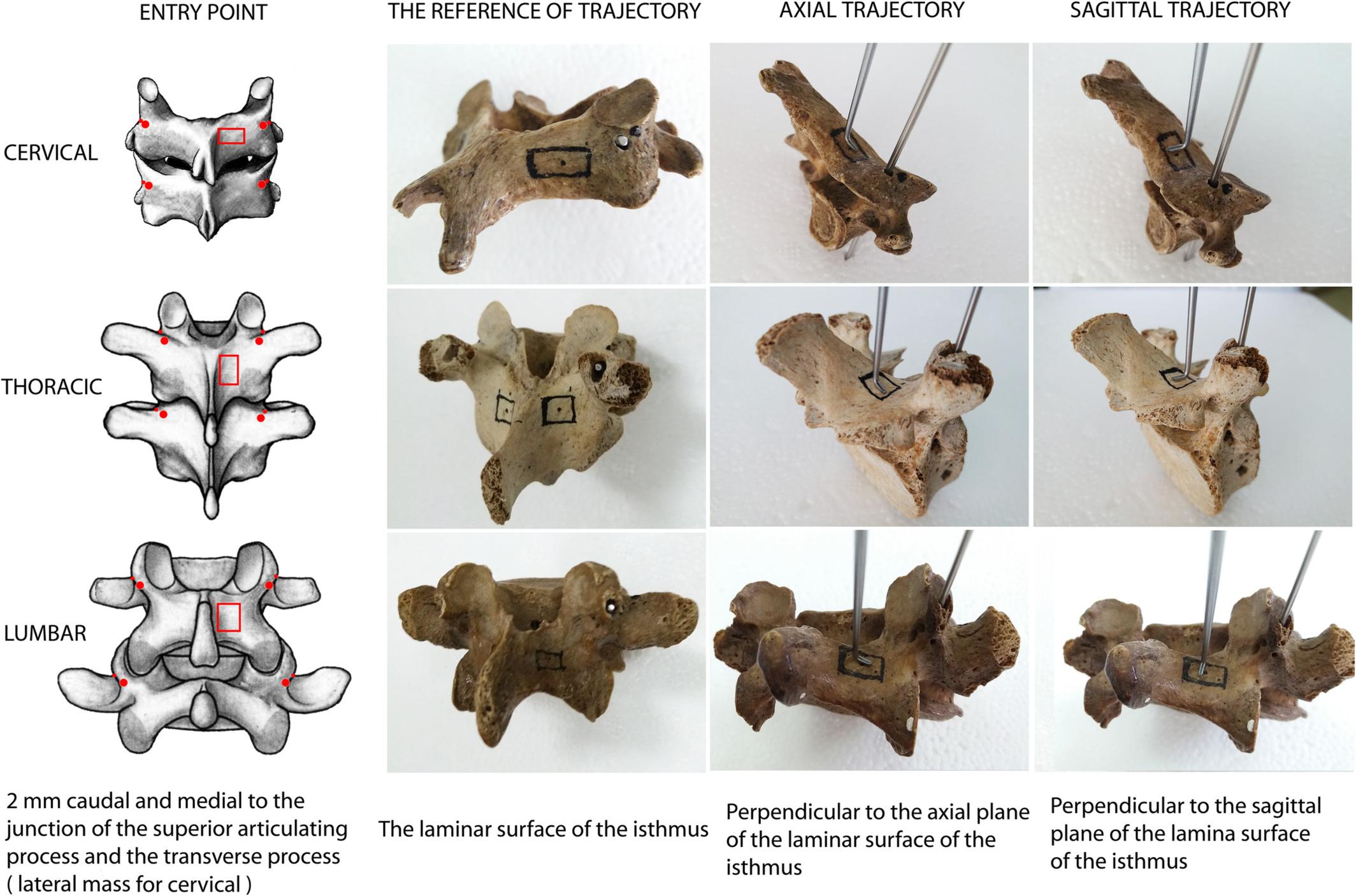
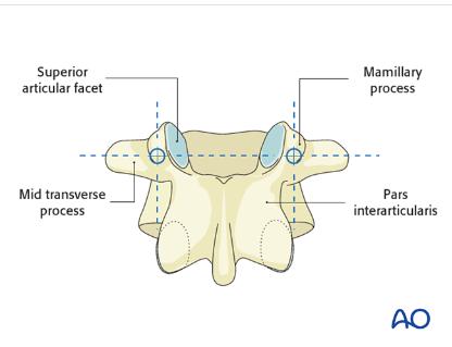
Lumbar: Confluenceofanyof:Parsinterarticularis,Mamillaryprocess,Lateralborderofsuperiorarticularfacet,Mid TransverseProcess
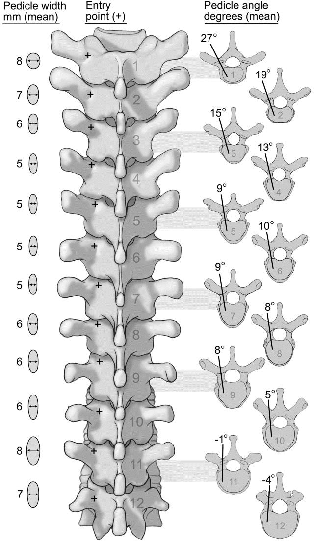
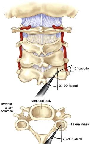
Thoracic: 2mm lateral and caudal to the intersection of the mid portion of facet joint and superior edge of transverseprocess.Movesmoresuperiorlywithhigherthoraciclevels
Cervical:2-3mmBelowinferioredgeofsuperiorfacet,5-6mmmedialtolateraledgeoflateralmass
B C D 10
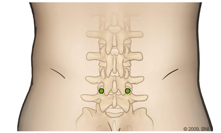
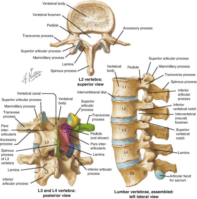
Figure 6: Anatomical Variations in Entry Points of Pedicle Screw Fixation. A) General Entry points for axial/sagittal trajectoriesateachspinallevel,B)LumbarSpineRelevantAnatomy(targetshighlightedinpurple/pink),C)OptimalAngles usedforThoracicSpinePedicleScrewFixation,D)CervicalSpinePedicleScrewFixationtrajectory
A
PEDICLE SCREW FIXATION
Indications
Internalthoracolumbarspinestabilisation
Standardprocedureforfractures,tumours,andmalunions Burstfractures,vertebralcompressivefracture
Degenerativedisease(spondylolisthesis,discherniation, spinalstenosis)
Kyphoticdeformities
Steps
1
Cortex Opening: Performed at respective entry points with a burr/rongeur Visualise cancellous bone of pedicle, advancing further with drill, gearshift, probe. The screw shouldtraverse80%ofthevertebralbody
Contraindications
Thoracicspine(unlesswithsenior):smallerpedicles,greater riskofcortexperforationandspinalcanalimpingement Congenitalsmallpedicles,parsdefect
Bilateralvertebralarteryinjuries
Difficultyinpronepositioning,trackerplacementornavigation Severespinaldeformitieswithaxialvertebralrotation Systemicdiseaseunabletowithstandanesthesia,surgery, radiationexposure
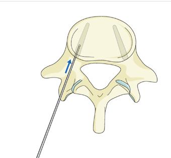
2 Medio-lateral inclination: Rotate to avoid medial penetration of spinal canal or anterior penetration of vertebral body cortex Screws should converge but remainentirelywithinpediclesandbody
4
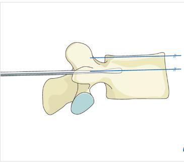
Cranial-Caudal Angulation: Pedicle probe to navigate down isthmus into vertebral body; Aim for contralateral transverse process to ensure parallelism with superior endplate At L1, horizontal angulation is 10-15 degrees but increasesby5degreesatlowerlevels
3 Screw Insertion: Pedicle sounding device with ball tip to palpate and confirm trajectory is complete. No breaches in pedicle wall apart from main trajectory should be detected A screw (monoaxial or polyaxial) of the right diameter measured by the device is inserted into the samepath.
AdditionalPoints
Depthcorrelateswithpulloutresistance,buttrade-off presentwithrisks(eg anteriorcortexrupture) Aimfor 80%pediclescrewinsertiontoprovidesafeandsufficient pulloutresistance
Morestraightforwardtrajectoriesandgreater convergencecanincreasepulloutresistance Pilotholetappingpriorscrewinsertionensurescorrect screwtrajectoryandensuresstabilityinpediclewalls Avoidoverdoing,whichmayweakentheimplant-bone interface
Undertapby1mm Avoidcreatingapilotholewiththe samesizescrew
FluoroscopyguidanceandRoboticarmsurgeryhave beendemonstratedtosignificantlyimproveaccuracy withreal-timeimaging,howeveratthecostofradiation exposureandlimitationswith2Dviews,on2planes
Benefits
Pedicleisthestrongestpartofposteriorspine-allowsfor stabilityandothercorrectiveprocedures(egderotation, translation) Canstable3columnsofDenis
Doesnotrequireintactlaminae,facetjointsorspinous processes
Providesappropriatereduction, adequatestabilisation,rapid spinalcorddecompressionandrapidimprovementin mobility
Fastrestorationofsagittal/coronalalignmentinkyphotic fractures
Limitations
Commonly results in late-onset discomfort/pain due to pseudoarthrosisorscrew-relatedissues
May cause nerve root irritation, superficial and deep wound infections
Misplacement,poorpositioningandbreachesarecommon
11 A B C D
Figure7:IllustrationofPedicleScrewFixation A) Entry Points, B) Cranial-CaudalAngulation,C)Medio-LateralInclination,D)Screw Insertion
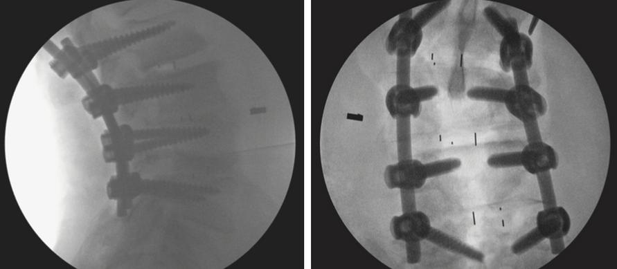
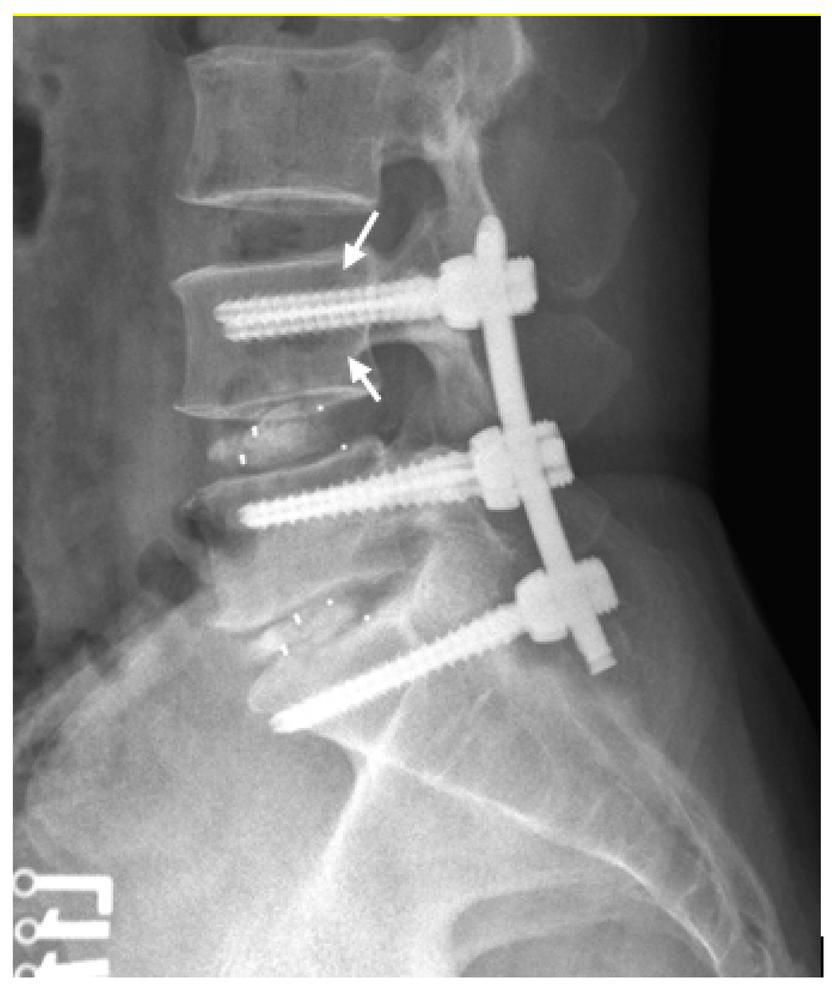
A B C D E
Figure8: Fluoroscopy-guided,RoboticPedicleScrewFixationA) Preoperativeplanningofentrypointsandtrajectory,B)-D)robot assistedpediclescrewplacement,E)Fluoroscopy-guidancing
DISCECTOMY
Indications
Emergencies:
Caudaequinasyndrome
Morphine-resistanthyperalgicsciatica Paralyzingsciatica(MRC<3),excludestoemuscles
Unremittingradicularsymptoms(confirmedbyMRI) softdischerniationsincervicalspine failureofmedicaltreatment
Alteredbowel/bladderfunction
Progressiveneurologicaldeficitsinlowerlimbs
AnatomicalConsiderations
EntryofSpinalRootrelativetovertebrae
Contraindications
Bonyspinalcanalstenosis
Overtsegmentalinstability
MalignantTumourswithDuralinvolvement
neurological/vascularpathologiessimilartodischerniations
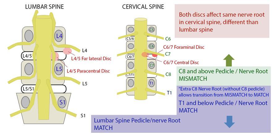
AboveC8,discherniationsalwaysaffectthenervebelowthelevel herniated(nervestravelsuperiortovertebrae)
BelowC8,discherniationsalwaysaffectnervesatthesamespinallevel (nervestravelinferiortovertebrae)
LocationofDiscProlapsealongspinallevel
Central:oftenbackpainonly,sometimesCaudaEquinaSyndrome
Posterolateral/paracentral:mostcommon,affectsrootbelow(eg L4-L5 prolapsehereaffectsL5)
Foraminal:leastcommon,affectsrootabove
Axillary:affectsboth
TypeofDiscPathology
Degeneration:Wearandtearofdisc;Generalisedbackpain
Prolapse:bulgewithinpulposus;localisedbackpain,muscleweakeness
Extrusion:pulposusthroughannulus;radiatingpain
Sequestration:discbreaksintospinalcanal;debilitatingradicularpain, lossofmusclepowerandurinary/boweldysfunction
Steps
1
Positioning:
Genupectoral;Freeabdomen,chestandeye protection a.
c
90°shoulderabductionandelbowflexion b Spineinkyphosistoexposeinterlaminarspace; Spineframe(WilsonorAllenBow)
2.
MarkingandIncision:Fluroscopy&Palpationof Sacrum,IliacCrests(Lumbar)orvertebra prominens/sternalnotch(Cervical);3to4-cm longitudinalincisiontoexposeinterspinousspace
Dissection:Electrocauterydissectionof subcutaneoustissue,revealslumbarfascia Blunt dissectionuntilfacetsarereached
3. Facetectomy/Laminectomy:Medialaspectofthe inferiorfacetofthesuperiorvertebramaybe resectedalongwithpartofthelaminatoallowfor exposure RemovalofLigamentumFlavumafterthis toexposehernia(LumbarRegion).
4. NerveRootconfirmationwithneuromonitoring
6
5. IncisionofPosteriorLongitudinalLigamentatthe pointofherniation
7.
DiscRemoval:Oncevisualised,pituitaryrongeurs areusedtoremovethediscinfragments
Benefits
Fasterpainreliefthannonsurgicaltreatment
Painrelieffromspinalcord
Enhancedmobilityandthereforebetterqualityoflife
Limitations
Wound/deepinfections(2-3%incidence)
AnteriorCervicalDiscectomypairedwithFusionenablesfor widerexposurewitheasieraccesstotheintervertebralspace reducespatientdiscomfort,andperioperative complicationratescomparedtoposteriorapproach
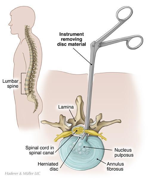
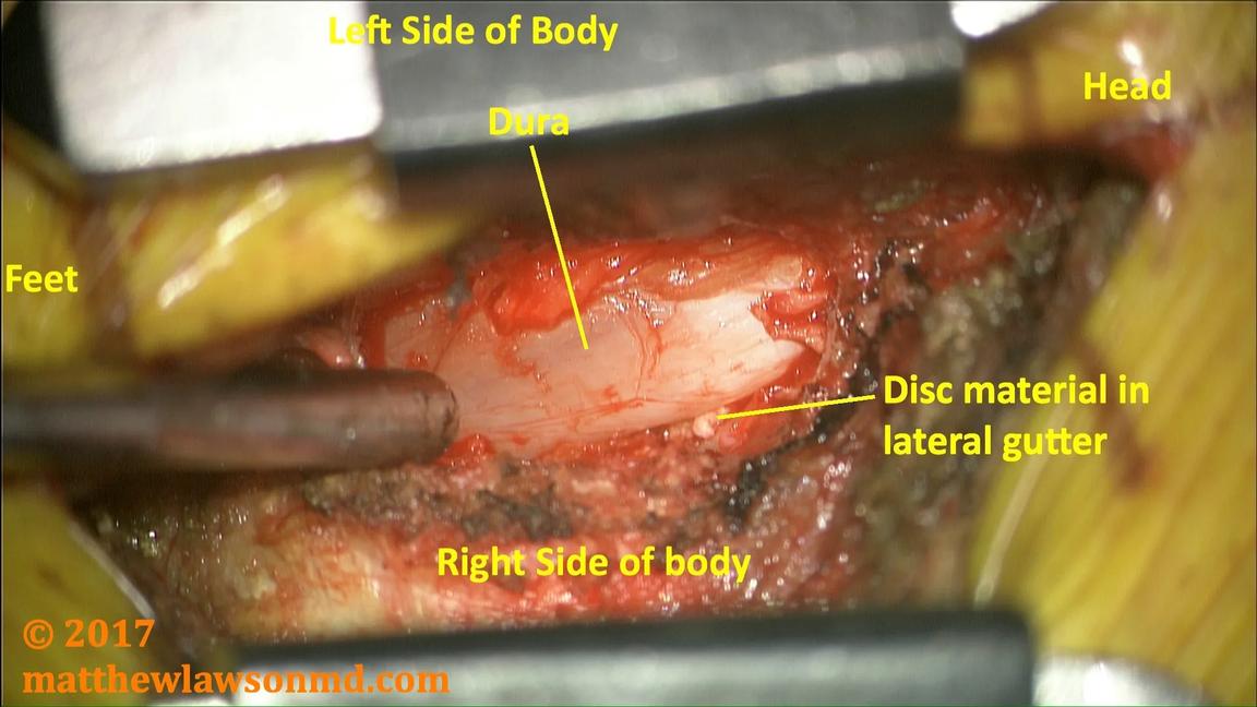
Illustrationofa Discectomy.
A)Positioningof Instrument,
B)Relevant Anatomy
C)Intraoperative viewofdiscectomy withpituitary rongeurs(right)
Intraoperativenerverootinjuryandincidentaldurotomypossible (1-6%)
canleadtoCSFleakpredisposingpatientstomeningitis Recurrenceofdiscprolapserangesfrom1-25%inLumbarregion, higheramongstmalesmokersandthoseunderheavylabour
Figure10:
12 A B C
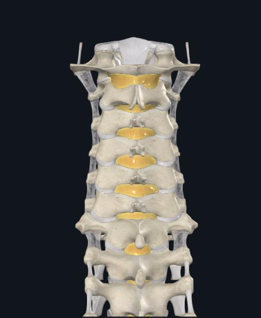
Figure9:EntryofSpinalRootsrelativetovertebrae
KYPHOPLASTY AND VERTEBROPLASTY
Indications
treatment of painful vertebral compression fractures secondary to osteoporosis refractory to conservative management treatment of painful vertebral compression fractures secondary to metastatic neoplasia, lymphoma, multiple myelomarefractorytoconservativemanagement patients with pain in the absence of a fracture, resulting from lytic metastatic neoplasm, or less commonly, symptomatichaemangioma
VertebralCompressionFractures(VCF)
Contraindications
Absolutecontraindications: activesystemicinfection insufficient cardiopulmonary health to undergo necessary anaesthesia(ASAscore)
epidural mass or posteriorly displaced bone compromising morethan50%ofthespinalcanal
Relativecontraindications: thrombocytopenia(requiresplatelettransfusionbeforehand) posteriorwalldehiscence(kyphoplastypreferred)
While compression fractures can occur anywhere in the spine, they typically occur in the thoracic spine, and less commonly,lumbarspine
fracturescanoccuratmorethanonelevel,resultinginheightlossandkyphosis
SymptomsofVCFinclude deeppain,midlinelocation,exacerbatedbymovement lateralradiationmaybepresentbutperistentradiationofpaininaradiculopathic fashionisrare.
whenthereissubstantialkyphosis;difficultybreathing,chestwallpainand gastrointestinaldiscomfortmayalsooccur
Aimsofkyphoplasty/vertebroplastyareto:
restorevertebralheight improvemobilityand functionaloutcomes relievepain-acutefracturewithpainclinicallyrespondingtothefracturedlevel respondsbest
Pre-ProcedureEvaluation
historyandphysicalexamination: symptoms as above physical examination should include palpation for focal areasoftendernessandcorrelationofsiteofpaintoanatomicallandmarks.Inchallengingcases,examinationof sitesofpainandtendernesscanbeperformedwithfluoroscopicassistance
Imaging:confirmspresenceandlocationoffracture(s),assessesdegreeofheightlossandkyphosis,andidentifies anatomicvariants Typically,radiographs(APandlateralviews),MRI(STIRsequence),andsometimesdualenergy CTscansforadditionalevaluation.
Benefits Risks and Complications
Dramaticincreaseinapatient’sfunctionalabilities;allowing themtoreturntopreviouslevelsofactivitywithouttheneedfor physiotherapy/rehabilitation
SuccessfulatalleviatingpaincausedbyVCFs;significantrelief almostimmediatelyafter Approximately75%ofpatientregainlostmobilityandprevious levelsofactivity,helpingimprovequalityoflifeandcombating conditionssuchasosteoporosis Usuallysafeandeffectiveprocedures. Nosurgicalincisionnecessary,nostitchesrequiredand thereforereducedriskofwoundsiteinfections
Leakageofcementoutsidethevertebralbodywhichcould causethermal(heat)damageandpressurecomplicationsin thespinalcanalincludingnerveinjury,andinseverecases, paralysis.. Cementsensitivitymayleadtoarrhythmiasincertainpatient groupsandcouldresultincardiacarrests.
Travellingofparticlesofcement,air,bonemarrowfator tumourintobloodvessels,causingemboli,whichmayresultin pulmonaryembolismsandstrokes
Hypothetically,increasedstrengthinvertebrafollowing kyphoplasty/vertebroplastymaymakeadjacentvertebrae moresusceptibletofracturesinthefuture
13
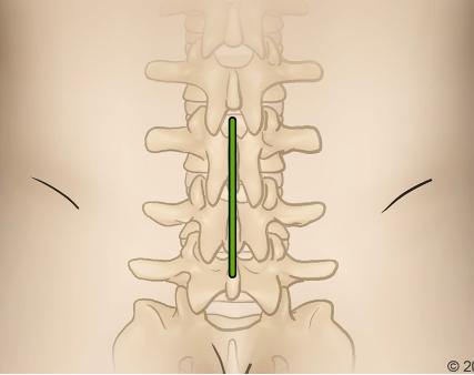
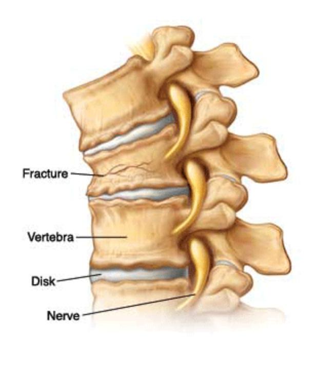
Figure11:IllustrationofaVertebral CompressionFracture
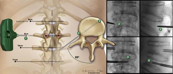
Figure12:EntrypointsandtrajectoriesoflowerthoracolumbarvertebralbodiesforPercutaneousVertebroplasty
VERTEBROPLASTY
Steps
2.
3
1. OperativeLevelIdentification:Identifytheoperative levelusingfluoroscopy.
PatientPositioning:Prone(thoracolumbar)forneedle placementfromeithersideandeasierpositioningofCarm Cushionstosupportheadandbody Adedicated biplanefluoroscopysuiteispreferred,butatleastone C-armunitisnecessary
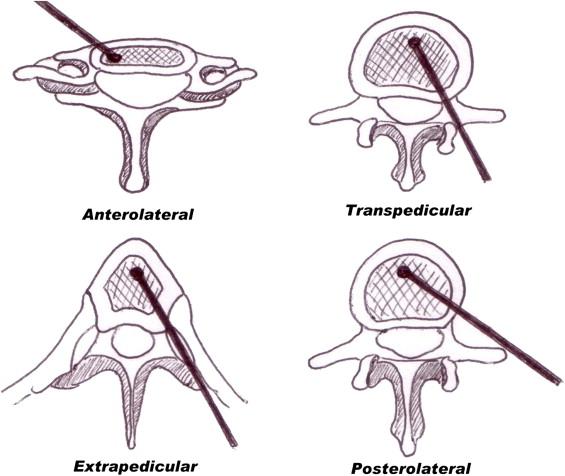
Needleplacement:
Transpedicular:needlethroughfulllengthofpedicle a
Parapedicular:needlealongthelateralcortexof pedicle b
TrajectorySafetyConsiderations
APviewsafetyconsiderations;(a)keeptomedialborderof pedicleinordertoavoidspinalcord/thecalsac,(b)don’t strayawayfromwithinpedicularborders,thiswillensure safetyofnervesandnerveroots lateralviewsafetyconsiderations;(a)cannulatipshouldbe seenattheposteriorbodywallinthelateralview,(b)the aorta/inferiorvenacavacanbedamagediftheanterior vertebralbodyispenetrated,(c)penetratingtheinferior pediclewallasaresultofimpropertrajectorycancause nervedamage
4.
Image-guidancestrategiesforatranspedicular approach:
a
b
Endontechnique:asdescribedbelowinthe kyphoplastyproceduredescription
APtechnique:craniocaudalangulationisadjusted sothattheendplatesareperpendiculartothe image.
i
Skinentrypoint1cmsuperolateraltopedicle’s centre,needleisadvancedanteriorly,medially andcaudally
iii
Needletipshouldinitiallyprojectovertheupper outercortexofthepedicle,needleisadvanced sotipprojectsovercentreofpedicleonAPand lateralviews
ii tipshouldbeoverthemedialpediclecortexas theneedlemovesacrosstheposteriorthirdof thevertebralbody.
Image-guidanceforaparapedicularapproach: Needleplacementissuperolateraltolateralpedicular cortex,entersthevertebralbodyatthejunctionofthe pedicleandvertebralbody
5. Cementplacement:fluoroscopicmonitoringis importanttoensurecementremainswithintheareaof target Lateralviewsaremoreimportantasitenables theevaluationoftheposteriorpositionofcement relativetospinalcanalandneuralforamina
7
6. ProcedureCompletion:postprocedureradiographsare takenandpatientismonitoredfor1-2hoursafter, includingneurologicassessment
AdditionalPoints
Needleshouldnotviolatethemedialcortexof pedicle
Trajectoryofneedlecannotbealteredmuchonce needlehaspassedintothepedicle
Avoidcannulacrossingmedialpedicularborder priorreachingposteriorwall(redline,Figure9A)to ensuresafetyandevendistributionofcement
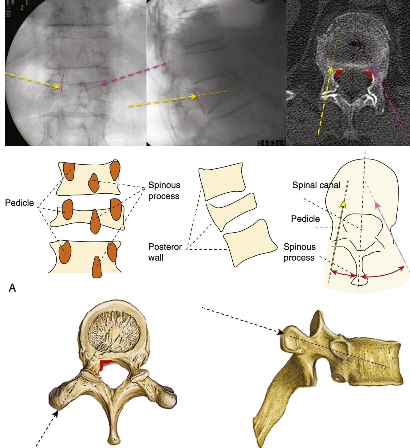
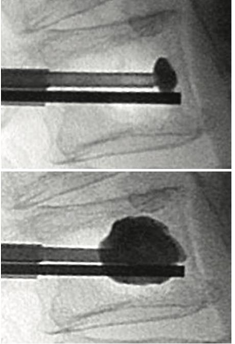
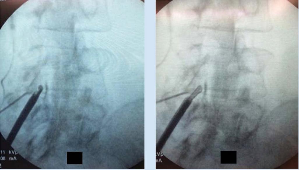
Figure13:Illustrationsof vertebroplasty.
A)Preoperativeplanningofentry pointsandtrajectory(yellow: bipedicularapproach;purple: unipedicularapproach;red:medial pedicularborder),
B)Simplifiedschematicsof relevantanatomicallandmarks andangulation
C)Approximatetrajectory, D)Lateralfluoroscopicviewof cementinjection
Benefits Limitations
smallerdeliverysystemhencelessinvasive fasterprocedure maybepossiblewhenkyphoplastyischallenging Transpedicular:longintraosseouspartwhichshieldsblood vesselsandnerverootsfromdirectinjury Transpedicular is commonly used and preferred, however the parapedicular approach can be used when there is difficulty in achieving the final needle tip position close to themidline
LesscontroloverPMMAdelivery(moreextravasation) Usuallylowervolumeinjections Thereisnoefforttoreducethefracture
14
A B C D
Steps
PatientPositioning:Prone,similartovertebroplasty
2
1. OperativeLevelIdentificationandimageguidance(using end-ontechniquedescribedpreviously):
a
APImaging:C-armadjustedtoaccommodate numerousanatomicallandmarks.Rotateobliquelyto positionpediclessymmetricallyandcenterspinous process Dependingoncase,rotatecraniocaudallyto squareupsuperiorandinferiorendplates,butnotalways possibleduetofracturenature.
b
LateralImaging:Superimposeanatomy,includingthe pediclesandendplates Asatisfactorylateralimagewill reflectclearvisualisationofthepedicleandforamenas wellasthesuperior,inferior,anteriorandposterior aspectsofthevertebralbody
4
3 Needleadvancement: Needlestartsatteno’clockmarkon theleftsideandtwoo’clockmarkontherightside(clockfaceanalogy) Theneedleisthenadvancedtothemedial borderofthepedicleandalateralfluoroscopicimageis obtained Oncethetipoftheneedleisconfirmedtobe anteriortotheposteriorvertebralmargin,itisfurther advancedintotheposteriorone-thirdofthevertebralbody Thisisrepeatedontheoppositeside.
SkinIncision:Incisionlateraltothelateralpedicularborder Whencontactwithboneismade,theneedleshouldbeatthe superolateralaspectofthepedicle.
5 Balloondeployment: ballooncathetersareinsertedthrough theaccesscannulasandsubsequentlydeployed Again, imagesaretakentoconfirmcorrectballoonplacement
7.
Confirmationofplacement:Onceaccessthroughthe pedicleshasbeenachieved,ahanddrillisusedocreatea channelforthesubsequentballoons APimageistakennow toconfirmplacement. Thisisrepeatedontheoppositeside.
6 Ballooninflationandcementinjection: Balloontampsare advancedbilaterally Eachballoontamp,attachedtoa lockingsyringewithadigitalmanometer,istheninflatedwith iodinatedcontrast APandlateralimagesareobtained duringinflationtoguaranteesafeandproperepansionand fracturereduction Onceexpansionisadequatelyperformed, balloonsaredeflatedand injectionofcementiscarriedout (cementcannulaisintroducedintoaccesscannulaforthis step). Enoughcementtofillvoidcreatedbyballoonsshould beinjected
8
Completionofprocedure:cementcannularemovedand styletneedleintroducedintoworkingcannula Oncecement hassecured,cannulais removedunderconstantimagingto detectanyposteriormigrationofcement
Benefits
BettercontrolofPMMAdelivery(cavitationcreation, balloondiversionandprotectionmeasures) potentialforfracturereduction flexibleinjectionoptions(forexample,creationofacavity linedbyPMMAwhichisallowedtohardenbeforetherestof thecementisinjected Thisensuresgreatercement deliverywithlowerriskofextravasation)
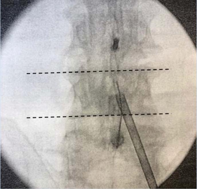
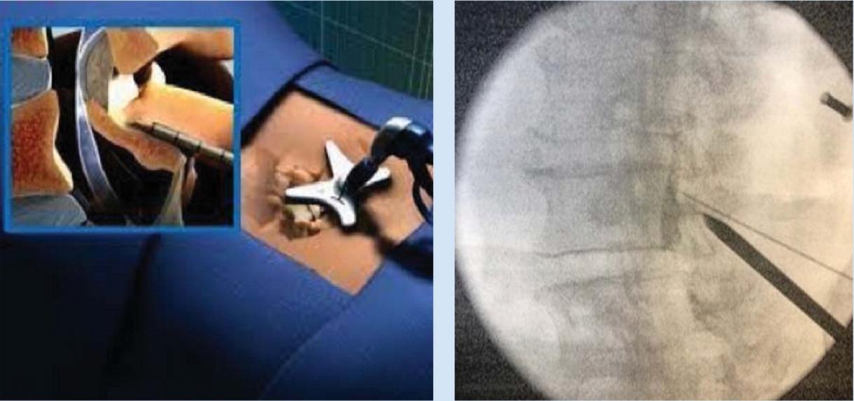
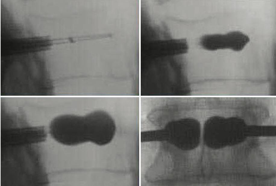
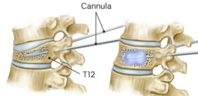
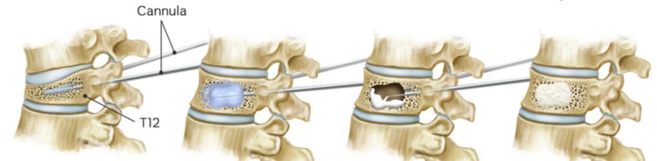
Figure14:IllustrationofKyphoplastyprocedure A)lateralfluoroscopicimagesofbonecementcannula insertion(topleft),ballooninflation(topright),bone cementevenlydistributedinvertebralbody(bottomleft), APviewofbilateralballoonkyphoplasty(bottomright) B)simplifiedillustrationofprocedure;needleadvanced intovertebralbody(topleft),ballooninflated(topright), balloondeflatedandcementinjected(bottomleft), cementin-situ(bottomright)
Limitations
Largerdeliverysystemrequired(usually8Gor10Gneedle) costofequipment trainingrequired
15 KYPHOPLASTY A B