Times Microwave Systems designs and manufactures high performance coaxial cables, connectors and cable assemblies for a broad range of RF transmission applications. For more than 50 years, Times has been the leader in the development of new cable technologies to meet the demands of evolving RF and microwave applications. This technological manufacturing and application leadership continues today.
Since its inception, Times has been dedicated to the improvement of coaxial cable technology and the development of new and innovative cable products to address the increasingly rigorous demands placed on RF transmission products.
The expertise that provided cable solutions for the demanding requirements of airborne electronic systems and led the way in the development of low smoke cables for shipboard applications is now yielding high performance cables to meet the needs of the wireless communications market with Times LMR low loss flexible coax cables.
Times has been instrumental in the development of commercial and military specifications, including MIL-C-17 for coaxial cables. Times is the leading source of MIL-C-17 qualified products, holding more QPL’s (Qualified Product Listings) than any other manufacturer in the world
Times applies its expertise to customer requirements through a staff of Field Application Engineers. Unlike other cable manufacturers with limited product lines who try to fit customer applications to their existing products, the philosophy of Times is to select or design the right product for each application.
This catalog serves as a guide to many of the products offered by Times and is a comprehensive technical reference with useful technical information on MIL-C-17 and RG cables.
(800)-TMS-COAX • www.timesmicrowave.com • (203)-949-8400 2
INTRODUCTION
(800)-TMS-COAX • www.timesmicrowave.com • (203)-949-8400 3 INDEX/TABLE OF CONTENTS Markets served ............................................................................................................................... 5 Complete reference data, interconnect system capability ........................................................... 6 HIGH PERFORMANCE CABLES M17 Select Cables .......... M17 type cables ............................................................................. 8 LSSB ................................ Low smoke cables ....................................................................... 10 LLSB ................................ Low loss, low smoke cable .......................................................... 12 StripFlex ........................... Flexible, low loss, strip braid ....................................................... 14 Strip Flex II ....................... Flexible, extra-low loss strip braid .............................................. 16 TCOM ............................... Low loss wireless communications cable................................... 18 TFlex ................................ Flexible, low loss alternate to semi-rigid cable .......................... 20 Coppersol ........................ Tubular copper and TFE dielectric .............................................. 22 Coppersol CLL ................ Tubular copper and expanded TFE dielectric ............................. 24
AND RG CABLES M17 cable descriptions .................................................................................................... 28-29 Attenuation and power tables ......................................................................................... 40-44 RG cable descriptions ...................................................................................................... 45-61 REFERENCE DATA AND APPLICATION NOTES Abbreviation key ..................................................................................................................... 64 Design equations and materials properties ..................................................................... 65,66 Application notes: A guide to the selection of RF coaxial cable .................................................................. 67-78
M17

(800)-TMS-COAX • www.timesmicrowave.com • (203)-949-8400 4
MARKETS SERVED

Military Aerospace
Times Microwave Systems coax cables are qualified for service on virtually every military aircraft platform for critical avionics and electronic warfare systems.

Military and Government Research
National research laboratories throughout the country rely on the engineering expertise of Times Microwave Systems for microwave, RF, high voltage and high power coax cables.


Commercial Aircraft
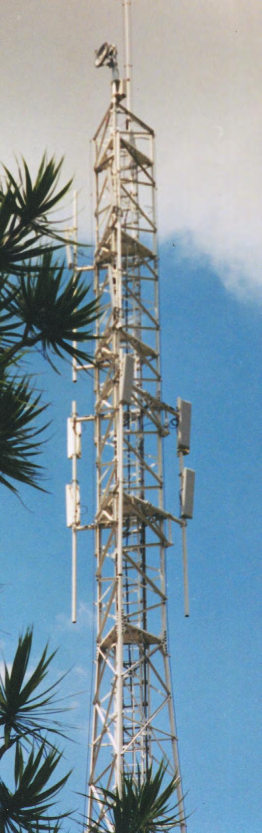
Military Ground-Based Communication Systems
Crucial radar and RF systems rely on high performance coax cables from Times Microwave Systems.
From navigational systems to TCAS (Traffic and Collision Avoidance Systems) and essentially every airborne avionics system, commercial passenger aircraft depend on coax cable from Times Microwave Systems
Wireless Telecommunications
Times Microwave Systems is a leader in providing flexible cabling solutions for the technological challenges of the rapidly evolving wireless industry.

Shipboard
Safety aboard military vessels is assured with Times Microwave Systems LLSB and LSSB fire retardant low-smoke generating coax cable.
(800)-TMS-COAX • www.timesmicrowave.com • (203)-949-8400 5
COMPLETE REFERENCE DATA
INTERCONNECT SYSTEM CAPABILITY
COMPLETE REFERENCE DATA
The correct selection of cable requires proper analysis of the electrical and physical parameters of the system. To assist you in this analysis, this catalog and handbook includes complete reference data enabling you to determine the characteristics of the cables presently available and also to evaluate how their characteristics may vary under various operating conditions. First, review the Application Notes section to determine the key characteristics which need to be considered. Then from the tabulations of M17, RG and Times high performance cables, the optimum cables may be selected.
COMPLETE INTERCONNECT SYSTEM CAPABILITY
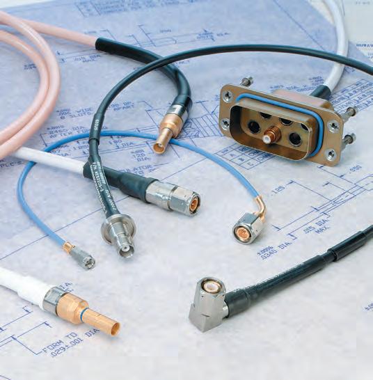
Since Times manufactures coax cable and connectors used in the entire RF transmission system, we are capable of taking full responsibility for the design and manufacture of all interconnections. Times maintains one of the largest and most modern stateof-the-art RF cable assembly facilities in the world, producing broadband coax cable assemblies to swept performance specifications. Times products are qualified and supplied on hundreds of critical system applications for commercial and military aerospace, electronic warfare (EW), shipboard and missile programs.
Products supplied by Times include:
• Flexible cables for shock-mounted applications.
• Lightweight and low-loss cables for air-frame equipment up to 40 GHz.
• Non-hosing cable to 1500 PSI for hull penetrations.
• Flexible coax cables for temperatures up to 250oC.
• High power applications.
• More than 10,000 coax cable designs! Times welcomes the opportunity to provide a solution to your most difficult RF transmission system problem, as well as your standard requirements.
(800)-TMS-COAX • www.timesmicrowave.com • (203)-949-8400 6
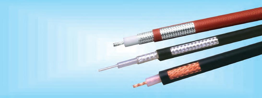
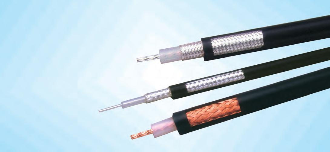
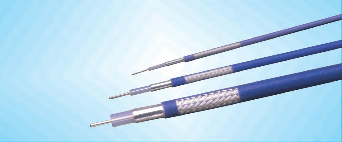
High Performance Coaxial Cables
M17 Select Cables, LSSB, LLSB®, StripFlex®, StripFlex® II, TCOM®, TFlex®, Coppersol, Coppersol Low Loss
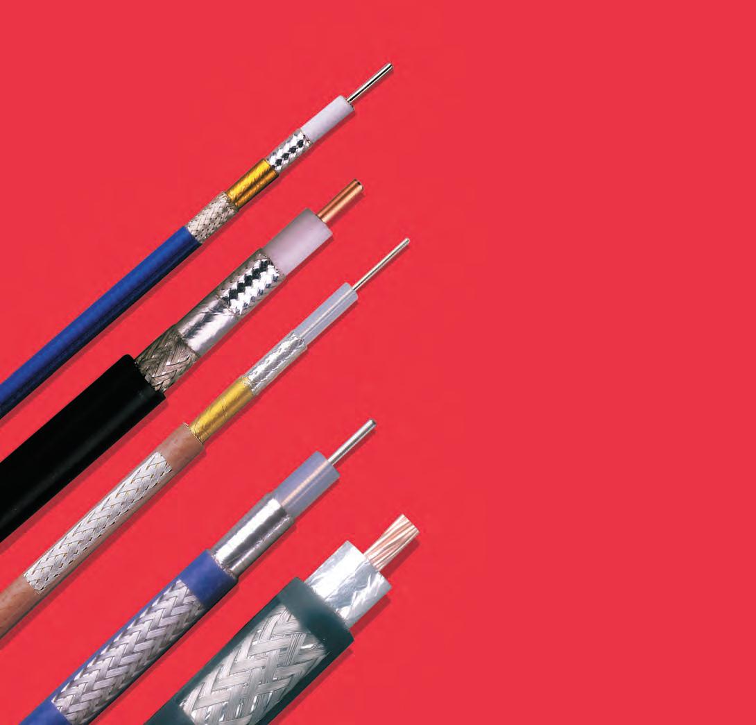
Special High Performance Coaxial Cables with Superior Electrical and Physical Characteristics compared to MIL-C-17 and RG Cables
(800)-TMS-COAX • www.timesmicrowave.com • (203)-949-8400 7
• Low Loss HF-UHF Interconnect
• Wireless Base Station Interconnect
‘Select’ Types and Sizes
Features & Benefits
• Meets all MIL-C-17 Requirements
• Good Shielding Effectiveness
• Low Passive Intermod (PIM)
• Readily available in Distribution
• Uses Standard Connectors
Attenuation (Loss) – again not the best by today’s standards but is usually acceptable at HF frequencies.
Attenuation Stability – silver plated outer conductor prevents oxidation of the conductors thereby minimizing attenuation change vs time. Conversely, bare copper outer conductors may oxidize quite rapidly precipitating loss increase which is only significant at frequencies > 500 MHz.
Power Handling – solid dielectric materials (high thermal conductivity) provides excellent power handling capability.
Temperature Range - broad operating temperature range.
Mechanical Properties – solid dielectric provides superior crush resistance and therefore is well suited for tactical applications.
M17/RG’s are traditional MIL Spec coax cables that were born 50-60 years ago. Originally created to support WWII military applications, these cables quickly became the products of choice for commercial wireless applications once they hit the surplus market, and continue to be used today.
M17/RG’s have been widely adopted for commercial and military applications. Their QPL stature insures a high quality product made to the same spec regardless of the manufacturer.
Some of the key characteristics of M17/RG’s are:
Shielding Effectiveness – in the 40 to 60 dB range and is acceptable for many lower frequency applications. Phase Stable – not the best for phase stability by today’s standards but can be optimized by appropriate preconditioning over the temp range of interest.
“Select” M17 Coaxial Cables
(800)-TMS-COAX • www.timesmicrowave.com • (203)-949-8400 8 M17/RG
M17 Conductor Dielectric Shields Jacket Weight Impedance Capacitance Oper. Temp. M17 Number inches inches inches inches lbs/foot ohms pF/foot Voltage Range Freq. (mm) (mm) (mm) (mm) (kg/m) Vp(%) (pF/m) Cent. Cond Shield kvrms F (C) Range M17/113-RG316 SCCS 7/.0067” PTFE 1:SC FEP-IX 0.012 50 +/- 2 29.4 83.3 8.5 1.2 -67 +392 .050.0201 0.060 0.078 0.098 3 (0.51) (1.52) (1.98) (2.49) (0.018) 69.5 (96.5) (273.3) (27.9) (-55 +200) GHz M17/84-RG223 SC PE 2:SC PVC-IIA 0.041 50 +/- 2 30.8 8.2 2.2 1.9 -40 +185 .040.0355 0.116 0.162 0.212 12.4 (0.90) (2.95) (4.11) (5.38) (0.061) 65.9 (101.1) (26.9)( 7.2) (-40 +85) GHz M17/60-RG142 SCCS PTFE 2:SC FEP-IX 0.043 50 +/- 2 29.4 19.1 2.2 1.9 -67 +392 .050.037 0.116 0.162 0.195 8 (0.94) (2.95) (4.11) (4.95) (0.064) 69.5 (96.5) (62.7) (7.2) (-55 +200) GHz M17/75-RG214 SC 7/.0296” PE 2:SC PVC-IIA 0.130 50 +/- 2 30.8 1.7 1.3 5.0 -40 +185 .050.0888 0.285 0.343 0.425 11 (2.26) (7.24) (8.71) (10.8) (0.194) 65.9 (101.1) (5.6) (4.3) (-40 +85) GHz M17/127-RG393 SC 7/.0312” PTFE 2:SC FEP-IX 0.175 50 +/- 2 29.4 1.5 1.3 5.0 -67 +392 .050.094 0.285 0.343 0.390 11 (2.39) (7.24) (8.71) (9.91) (0.261) 69.5 (96.5) (4.9) (4.3) (-55 +200) GHz
DC Resistance ohms/1kft (/km)
• Low Passive Intermod (silver plated types)
• Where MIL Spec Pedigree is Required
• Tactical Field Antenna Feeders

(800)-TMS-COAX • www.timesmicrowave.com • (203)-949-8400 9
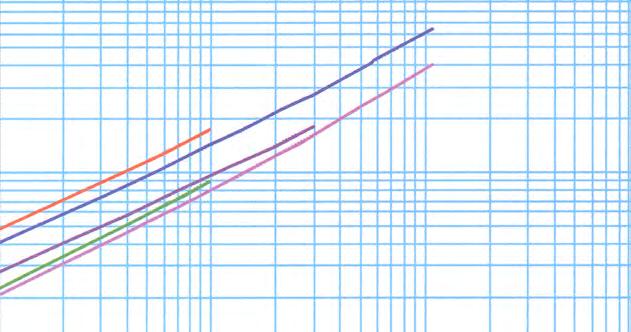
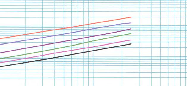
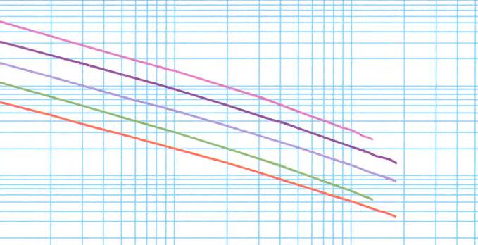
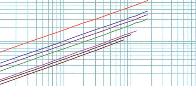
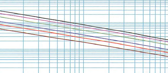
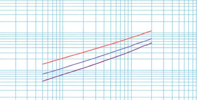
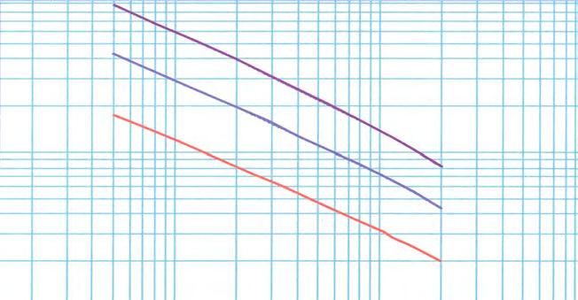
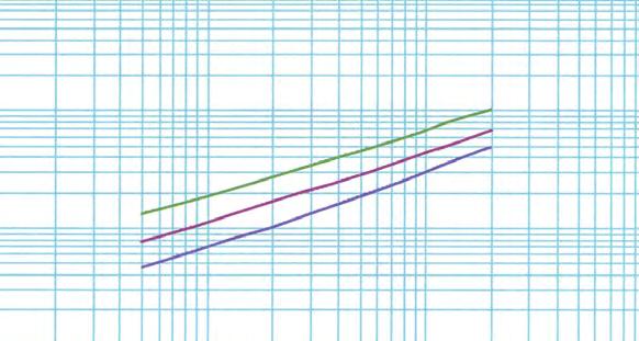
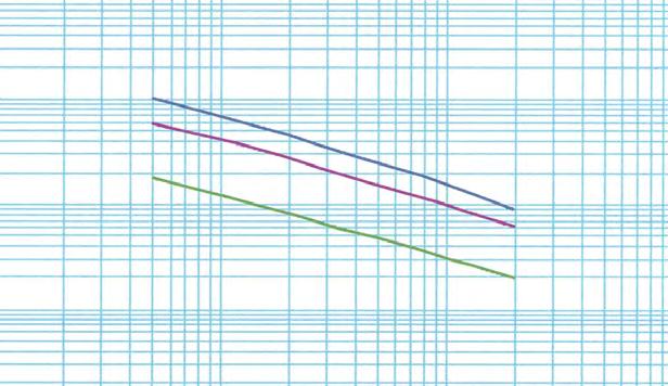
Frequency (MHz) 10 30 50 100 400 1,000 1,500 2,000 2,500 3,000 10,000 M17/RG-393 15141 8612 6604 4584 2156 1275 1000 838 729 649 286 M17/RG-142 5601 3206 2468 1726 831 504 401 340 298 267 125 M17/RG-214 3181 1808 1386 961 451 266 209 175 152 135 59 M17/RG-316 1869 1072 827 580 282 173 138 118 104 93M17/RG-223 1081 619 476 333 161 97 78 66 58 52 24 Watts; Sea Level; Ambient +40C; VSWR 1:1 Frequency (MHz) Power Handling vs. Frequency (Maximum) 10,000 1,000 100 10 100 1,000 10,000 Power (watts) M17/RG-393 M17/RG-142 M17/RG-214 M17/RG-316 M17/RG-223 Frequency (MHz) Frequency (MHz) 10 30 50 100 400 1,000 1,500 2,000 2,500 3,000 10,000 k1 k2 M17/RG-316 2.5 4.3 5.6 8 16 26 32 38 42 47 - 0.787 0.00120 M17/RG-223 1.2 2.1 2.8 4 8 13 17 20 22 25 51 0.384 0.00126 M17/RG-142 1.2 2.1 2.7 4 8 13 16 19 21 24 49 0.368 0.00120 M17/RG-214 0.7 1.2 1.6 2.2 4.7 7.9 10 11.9 13.7 15.3 37 0.210 0.00126 M17/RG-393 0.6 1.1 1.4 2.0 4 7 9 11 13 14 31 0.202 0.00120 Attenuation at Any Frequency = [ k1 x SQRT (Fmhz)] + [ k2 x Fmhz ]; dB per 100 feet
Frequency
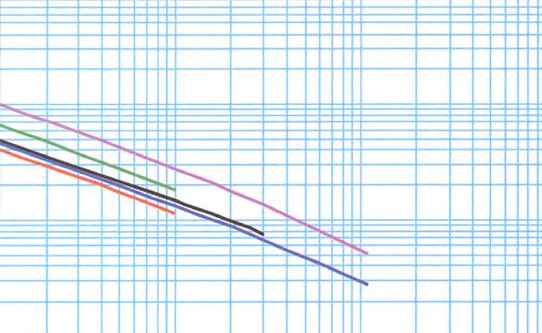
100 10 1 100 1,000 10,000 Attenuation (db per 100 feet) M17/RG-316 M17/RG-223 M17/RG-142 M17/RG-214 M17/RG-393
Attenuation vs.
(Typical)
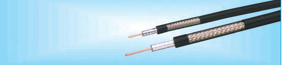
LSSB™
Low Smoke - Non-Halogen Military/Aerospace Coax
Features & Benefits
• Rugged Abrasion Resistant Jacket
• Excellent Shielding Effectiveness
• Fire Retardant (non-halogen)
• Light Weight
• Flexible for Ease of Deployment
• Excellent Connector Selection
• MIL-Spec Air Frame, Shipboard, Ground (Tactical)
• Flexible: With very tight minimum bend radius, LSSB cable can be easily routed into and through tight spaces. Ideal for tactical deployment and retrieval.
• Excellent Loss: LSSB has lower loss than other cables of the same size and and is significantly less than the M17 spec requirement.
• Fire Retardant: A black UV resistant non-halogen Low Smoke - Fire Retardant cross-linked polyethylene jacket makes the cable rugged and resistant to the full range of military/defense environments. LSSB cables easily achieve FAR 25, NES-711, NES-713 compliance.
• RF Shielding: High coverage (>95%) braids, result in >40-60 dB RF shielding (>80 dB - 120 dB crosstalk) and excellent interference immunity (ingress and egress).
• Connectors and Assemblies: A full range of connector interfaces is available in crimp or clamp styles. Custom pre-terminated and tested assemblies with phase matching, insertion loss matching, and other special electrical or marking requirements can also be provided.
LSSB Shipboard Coaxial Cables
See M17 tables for additional sizes and armored versions
(800)-TMS-COAX • www.timesmicrowave.com • (203)-949-8400 10
TMS & M17 Conductor Dielectric Shields Jacket Weight Impedance Capacitance Oper. Temp. Test Number inches inches inches inches lbs/foot ohms pF/foot Voltage Range Freq. (mm) (mm) (mm) (mm) (kg/m) Vp(%) (pF/m) Cent. Cond Shield (s) kvrms F (C) LSSB-RG6 CCS PE 34 SC: 34 BC XLPE 0.092 75 +/- 3 20.6 32.2 1.1 2.7 -22 +176 3 M17/180-00001 0.0285 0.185 0.243 0.332 GHz (0.72) (4.70) (6.17) (8.43) (0.137) 65.9 (67.6) (105.6) (3.6) (-30+80) LSSB-RG11 TC 7/.0159 PE 33 BC XLPE 0.142 75 +/-3 20.6 6.1 1.2 5.0 -22 +176 3 M17/181-00001 0.0477 0.285 0.318 0.405 GHz (1.21) (7.24) (8.08) (10.29) (0.212) 65.9 (67.6) (20.0) (3.9) (30+80) LSSB-RG58 TC 19/.0072 PE 36 BC XLPE 0.03 50 +/-2 30.8 10.9 4.1 1.9 -22 +176 0.05M17/183-00001 0.0355 0.116 0.139 0.195 1 (0.900) (2.95) (3.53) (4.95) (0.045) 65.9 (101.1) (35.8) (13.5) (-30 +80) GHz LSSB-RG214 SC 7/.0296 PE 34 SC:34 SC XLPE 0.154 50 +/-2 30.8 1.7 1.3 5.0 -22 +176 0.05M17/190-00001 0.089 0.285 0.343 0.425 11 (2.26) (7.24) (8.71) (10.80) (0.229) 65.9 (101.1) (5.6) (4.3) (-30 +80) GHz LSSB-RG223 SC PE 36 SC:36 SC XLPE 0.044 50 +/-2 30.8 8.2 2.2 1.9 -22 +176 0.05M17/194-00001 0.035 0.116 0.162 0.212 2.5 (0.889) (2.95) (4.11) (5.38) (0.066) 65.9 (101.1) (26.9) (7.2) (-30 +80) GHz
DC Resistance ohms/1kft (/km)
Interconnect (M17/180 –/200, /210–/218)
• Fire Retardant / Low Smoke (non-halogen)
• Flexible For Easy Deployment / Routing
(800)-TMS-COAX • www.timesmicrowave.com • (203)-949-8400 11
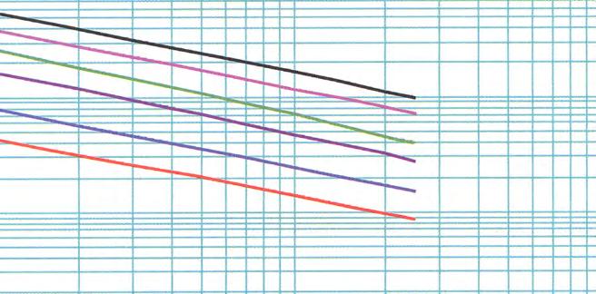
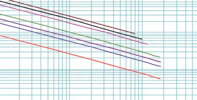
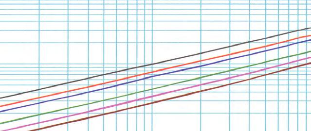
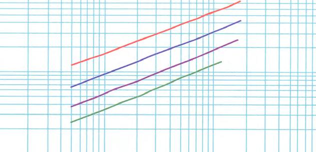
Frequency (MHz) 10 30 50 100 400 1,000 1,500 2,000 2,500 3,000 11,000 LSSB-RG214 3549 2003 1528 1051 481 276 213 177 152 134 51 LSSB-RG11 2430 1364 1037 709 318 179 - - - -LSSB-RG6 1678 957 736 513 244 146 116 97 85 76LSSB-RG223 1558 887 680 472 223 132 103 87 75 67 27 LSSB-RG58 1412 800 612 423 196 114 - - - -Watts; Sea Level; Ambient +40C; VSWR 1:1 Frequency (MHz) Power Handling vs. Frequency (Typical) 10,000 1,000 100 10 100 1,000 10,000 100,000 Power (watts) LSSB-RG214 LSSB-RG11 LSSB-RG6 LSSB-RG223 LSSB-RG58 Frequency (MHz) Frequency (MHz) 10 30 50 100 400 1,000 1,500 2,000 2,500 3,000 11,000 k1 k2 LSSB-RG58 1.4 2.5 3.3 4.6 10.2 17 - - - - - 0.444971 0.003370 LSSB-RG223 1.2 2.2 2.8 4.1 8.6 14 18 22 25 28 65 0.383488 0.002232 LSSB-RG6 0.8 1.5 1.9 2.7 5.7 9.6 12 14 16 18 - 0.262144 0.001264 LSSB-RG11 0.7 1.2 1.6 2.3 5.1 6.9 - - - - - 0.202970 0.002527 LSSB-RG214 0.6 1.1 1.4 2.1 4.6 7.9 10 12 14 16 41 0.191365 0.001895 Attenuation at Any Frequency = [ k1 x SQRT (Fmhz)] + [ k2 x Fmhz ]; dB per 100 feet
(Typical) 100 10 1 100 1,000 10,000 100,000 Attenuation ( db per 100 feet) LSSB-RG58 LSSB-RG223 LSSB-RG6 LSSB-RG11 LSSB-RG214
Attenuation vs. Frequency
LLSB®
Low Loss – Military/Aerospace Coax
Features & Benefits
• Low Loss
• Superior Shielding Effectiveness
• Fire Retardant (non-halogen)
• Light Weight
• Flexible for Ease of Deployment
• Excellent Connector Selection
• Low Loss Air Frame, Shipboard, Ground (Tactical) Interconnect
• Flexible: With very tight minimum bend radius, LLSB cable can be easily routed into and through tight spaces without kinking. The bonded-tape outer conductor provides superior flexibility and ease of bending compared to previous generation M17/RG type, corrugated copper, or smooth wall copper hard-line cables.
• Low Loss: LLSB has lower loss than other cables of the same size. This is achieved through the use of a high velocity dielectric and bonded aluminum tape outer conductor. The proprietary gas-injected closed cell foam dielectric prevents water migration through the cable and provides excellent crush resistance.
• Fire Retardant: A black UV resistant non-halogen Low Smoke - Fire Retardant cross-linked polyethylene jacket makes the cable rugged and resistant to the full range of military/defense environments. LLSB cables easily achieve FAR 25, NES-711, NES-
713 compliance.
• RF Shielding: The bonded aluminum tape outer conductor is overlapped to provide 100% coverage, resulting in >90 dB RF shielding (>180 dB crosstalk) and excellent interference immunity (ingress and egress).
• Phase Stability: The intimately bonded structure and foam dielectric of LLSB cables provide excellent phase stability over temperature and with bending. The high velocity dielectric results in superior phase stability as compared with solid and air-spaced dielectric cables.
• Connectors and Assemblies: A full range of connector interfaces is available in crimp or clamp styles in addition to supporting installation tools. Custom preterminated and tested assemblies with phase matching, insertion loss matching, and other special electrical or marking requirements can also be provided.
LLSB Shipboard Coaxial Cables
(800)-TMS-COAX • www.timesmicrowave.com • (203)-949-8400 12
TMS & M17 Conductor Dielectric Shields Jacket Weight Impedance Capacitance Oper. Temp. Test Number inches inches inches inches lbs/foot ohms pF/foot Voltage Range Freq. (mm) (mm) (mm) (mm) (kg/m) Vp(%) (pF/m) Cent. Cond Shield (s) kvrms F (C) LLSB-200 BC Foam PE Alum Tape; XLPE 0.037 50 +/- 2 24.5 5.4 4.9 1.0 -22 +185 0.05M17/220-00001 0.044 0.118 36 TC 0.195 2.5 (1.12) (2.95) 0.144 (3.66) (4.95) (0.055) 83 (80.4) (17.7) (16.1) (-30 +85) GHz LLSB-240 BC Foam PE Alum. Tape; XLPE 0.051 50 +/-2 24.2 3.2 3.9 1.5 -22 +185 0.05M17/221-00001 0.056 0.150 36 TC 0.242 2.5 (1.42) (3.81) 0.178 (4.52) (6.15) (0.076) 84 (79.4) (10.5) (12.8) (-30+85) GHz LLSB-400 BCCAI Foam PE Alum Tape; XLPE 0.114 50 +/-2 23.9 1.39 1.65 3.0 -22 +185 0.05M17/223-00001 0.108 0.285 34 TC 0.405 2.5 (2.74) (7.245) 0.320 (8.13) (10.29) (0.170) 85 (78.4) (4.6) (5.4) (-30 +85) GHz LLSB-600 BCCAI Foam PE Alum Tape; XLPE 0.168 50 +/-2 23.4 0.53 1.20 5.0 -22 +185 0.05M17/225-00001 0.176 0.455 33 TC 0.590 2.5 (4.47) (11.56) 0.490 (12.45) (14.99) (0.250) 87 (76.8) (1.74) (3.94) (-30 +85) GHz LLSB-900 BC Tube Foam PE Alum Tape; XLPE 0.375 50 +/-2 23.4 0.54 0.55 7.0 -22 +185 0.05M17/226-00001 0.262 0.680 30 TC 0.870 2.5 (6.65) (17.27) 0.732 (18.59) (22.108) (0.559) 87 (76.8) (1.78) (1.80) (-30 +85) GHz LLSB-1200 BC Tube Foam PE Alum Tape; XLPE 0.686 50 +/-2 23.1 0.32 0.37 8.0 -22+185 0.05M17/227-00001 0349 0.920 30 TC 1.200 2.5 (8.86) (23.37) 0.972 (24.69) 30.48 (1.022) 88 (75.8) (1.06) (1.21) (-30 +85) GHz See page 39 for additional sizes and armored versions DC Resistance ohms/1kft(/km)
• Fire Retardant / Low Smoke (non-halogen)
• Flexible For Easy Deployment / Routing
(800)-TMS-COAX • www.timesmicrowave.com • (203)-949-8400 13
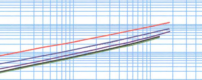
Frequency (MHz) 10 30 50 100 400 1,000 1,500 2,000 2,500 LLSB-1200 (M17/227) 18953 10835 8337 5823 2795 1689 1342 1137 998 LLSB-900 (M17/226) 13044 7477 5763 4038 1959 1197 958 815 718 LLSB-600 (M17/225) 9392 5291 4031 2767 1257 718 554 458 394 LLSB-400 (M17/223) 5720 3254 2495 1732 815 482 379 318 277 LLSB-240 (M17/221) 2592 1490 1150 809 397 245 198 169 150 LLSB-200 (M17/220) 1459 840 649 457 225 140 113 97 86 Watts; Sea Level; Ambient +40C; VSWR 1:1 Frequency (MHz) Power Handling vs. Frequency (Typical) 100 1,000 10,000 Power (watts) LLSB 1200 (M17/227) LLSB 900 (M17/226) LLSB 600 (M17/225) LLSB 400 (M17/223) LLSB 240 (M17/221) LLSB 200 (M17/220) Frequency (MHz) Frequency (MHz) 10 30 50 100 400 1,000 1,500 2,000 2,500 k1 k2 LLSB-200 (M17/220) 1.2 2.1 2.7 3.8 7.7 12 15 18 20 0.377530 0.000380 LLSB-240 (M17/221) 0.8 1.3 1.7 2.5 5.0 8 10 12 13 0.242084 0.000397 LLSB-400 (M17/223) 0.4 0.7 0.9 1.3 2.8 4.7 5.9 7.0 8.1 0.14387 0.00031 LLSB-600 (M17/225) 0.2 0.4 0.6 0.8 1.8 3.2 4.2 5.0 5.9 0.08888 0.00031 LLSB-900 (M17/226) 0.2 0.3 0.4 0.6 1.3 2.1 2.6 3.1 3.5 0.060910 0.000188 LLSB-1200 (M17/227) 0.1 0.2 0.3 0.5 1.0 1.6 2.0 2.3 2.7 0.043960 0.000188 Attenuation at Any Frequency = [ k1 x SQRT (Fmhz)] + [ k2 x Fmhz ]; dB per 100 feet
Frequency (Typical) 100.0 10.0 1.0 0.1 10,000 1000 100 10 100 1,000 10,000 Attenuation (db per 100 feet) LLSB 200 (M17/220) LLSB 240 (M17/221) LLSB 400 (M17/223) LLSB 600 (M17/225) LLSB 900 (M17/226) LLSB 1200 (M17/227)
Attenuation vs.
StripFlex®
Low Loss – High Performance Coax
Features
& Benefits
• Lower Loss than M17/RG Versions
• Superior Shielding Effectiveness
• Stable Loss & VSWR vs Flexing
• Readily Available RG Type Connectors
• Low Loss Microwave Interconnect
• Wireless Base Station Interconnect
StripFlex cables are identical in materials and construction to their M17/RG predecessors, with the exception of the outer conductor.
The StripFlex shielding system , pioneered by Times Microwave Systems in the mid-sixties, consists of an inner silver plated flat ribbon braid (FSC), a spirally applied and overlapped composite aluminum tape interlayer (Intl), and an overall silver plated round wire braid (SC). The StripFlex shield affords approximately 15% lower loss and >95 dB shielding compared with the typical M17/RG round wire braided shield (40 to 60 dB).
Standard M17/RG cables are shielded with high coverage single or double round wire braids. While these shields provide 40 dB and 60 dB shielding effectiveness respectively, they are not particularly
stable (loss & vswr) nor is the shielding adequate for today’s sensitive wireless communications and microwave military/defense applications.
VSWR is lower since the flat ribbons can be applied over the dielectric much more uniformly than multiend round wire braids. The VSWR and attenuation variation due to aging and flexure is substantially lower at all frequencies, and especially above 12 GHz. StripFlex cables are also available from Times that have been sweep tested for broadband VSWR and attenuation performance. Please contact the factory with your specific requirements.
Standard inexpensive connectors (crimp or clamp style) commonly used on the M17/RG counterparts can be used on StripFlex.
StripFlex Low Loss High Performance Coaxial Cables
(800)-TMS-COAX • www.timesmicrowave.com • (203)-949-8400 14
TMS Conductor Dielectric Shields Jacket Weight Impedance Capacitance Oper. Temp. Min. Bend Test Number inches inches inches inches lbs/foot ohms pF/foot Voltage Range Radius Freq. (mm) (mm) (mm) (mm) (kg/m) Vp(%) (pF/m) Cent. Cond Shield kvrms F (C) in (mm) SF-316 SCCS 7/.0067” PTFE FSC FEP-IX 0.013 50 +/- 1 29.4 83.3 4.4 1.2 -67 +392 0.5 .050.0201 0.060 Intl: SC 0.110 3 (0.51) (1.52) 0.093 (2.36) (2.79) (0.019) 69.5 (96.5) (273.3) (14.4) (-55 +200) (12.7) GHz SF-142B SCCS PTFE FSC FEP-IX 0.043 50 +/- 1 29.4 19.1 2.9 1.9 -67 +392 1 .050.037 0.116 Intl: SC 0.195 18 (0.94) (2.95) 0.154 (3.91) (4.95) (0.064) 69.5 (96.5) (62.7) (9.4) (-55 +200) (25.4) GHz SF-304 SCCS PTFE FSC FEP-IX 0.105 50 +/- 1 29.4 7.5 1.7 3.0 -67 +392 1.5 .050.059 0.185 Intl: SC 0.290 18 (1.50) (4.70) 0.231 (5.87) (7.37) (0.1564) 69.5 (96.5) (24.6) (5.4) (-55 +200) (38.1) GHz SF-214 SC 7/.0296” PE FSC PVC-IIA 0.116 50 +/- 1 30.8 1.71 1.36 5.0 -40 +176 2 .050.0888 0.285 Intl: SC 0.425 0.116 12 (2.26) (7.24) 0.330 (8.38) (10.8) (0.173) 65.9 (101) (5.6) (4.5) (-40 +80) (50.8) GHz SF-393SC 7/.0312” PTFE FSC: FEP-IX 0.188 50 +/- 1 29.4 1.54 1.08 5.0 -67 +392 2 .050.094 0.285 Intl: SC 0.390 12 (2.39) (7.24) 0.330 (8.38) (9.91) (0.280) 69.5 (96.5) (5.1) (3.5) (-55 +200) (50.8) GHz DC Resistance ohms/1kft (/km)
• Low Passive Intermod
(800)-TMS-COAX • www.timesmicrowave.com • (203)-949-8400 15 SF-316 SF-142 SF-304 SF-214 SF-393 Frequency (MHz) 100 400 1,000 2,000 3,000 5,000 10,000 12,000 13,500 16,000 18,000 SF-393 5303 2474 1450 946 729 517 315 274 251 - -SF-304 3192 1514 903 599 467 336 210 184 169 149 136 SF-142 1796 864 522 352 277 202 129 114 105 93 85 SF-214 1102 515 302 197 152 108 66 58 53 -SF-316 672 328 200 136 108 80 52 46 42 38 35 Watts; Sea Level; Ambient +40C; VSWR 1:1
•
•
Frequency (MHz) Frequency (MHz) 100 400 1,000 2,000 3,000 5,000 10,000 12,000 13,500 16,000 18,000 k1 k2 SF-316 7.2 15 24 34 42 56 83 92 98 109 117 0.708 0.00120 SF-142 3.6 7.4 12 18 23 31 47 53 57 63 68 0.348 0.00120 SF-304 2.4 5.1 8.5 13 16 22 35 40 43 48 53 0.231 0.00120 SF-214 1.8 3.9 6.7 10 13 18 30 34 37 - - 0.172 0.00126 SF-393 1.8 3.8 6.4 10 13 18 28 32 35 - - 0.164 0.00120 Attenuation at Any Frequency = [ k1 x SQRT (Fmhz ] + [ k2 x Fmhz ]; dB per 100 feet Frequency (MHz) Attenuation vs. Frequency (Typical) 1,000 100 10 1 Attenuation (db per 100 feet) 100 1,000 10,000 100,000 Power Handling vs. Frequency (Maximum) 10,000 1,000 100 10 100 1,000 10,000 100,000 Power (watts) SF-393 SF-304 SF-142 SF-214 SF-316
High Temperature /Low Temperature
High Power
StripFlex®-II (SFT)
Low Loss – High Performance Coax
Features & Benefits
• Lower Loss than SF Versions
• Superior Shielding Effectiveness
• Low Passive Intermod (-155 dBc)
• Stable Loss & VSWR vs. Flexing
• Excellent Connector Selection
• Lower Loss Microwave Interconnect
• Wireless Base Station Interconnect

StripFlex II cables provide the ultimate performance in a flexible cable. The low density PTFE tape dielectric provides the lowest dielectric loss of any practical dielectric and silver plated conductors make these the ideal choice for microwave and military interconnect systems
The high temperature dielectric and jacket enable their use in high ambient temperatures up to +200°C. They have losses slightly smaller than their low temperture TCOM counterparts as well as higher power handling capability.
The Shielding system, provided by times Microwave Systems in the mid-sixties, consists of an inner silver plated flat ribbon braid (FSC), a spirally applied and overlapped composite aluminum tape interlayer (Intl), and an overall silver plated round wire braid (SC). The flat ribbon shield affords approximately 30% lower loss and >95 dB shielding compared with the typical M17/ RG round wire braided shield (40 to 60 dB).
Standard M17/RG cables are shielded with high coverage single or double round wire braids. While these shields provide 40 dB and 60 dB shielding effectiveness respectively, they are not particularly stable (loss & vswr) nor is the shielding adequate for today’s sensitive wireless communications and microwave military/defense applications.
VSWR is lower since the flat ribbons can be applied over the dielectric much more uniformly than multi end round wire braids. The VSWR and attenuation variation due to aaging and flexure is substantially lower at all frequencies, and especially above 12 GHz. StripFlex II cables are also available from Times that have been sweep tested for broadband VSWR and attenuation performance. Please contact the factory with your specific requirements.
A good selection of interface connectors (crimp or clamp style) are available. SFT cables can be purchased in bulk reels or as predetermined and tested cable assemblies.
StripFlex II Low Loss High Performance Coaxial Cables
(800)-TMS-COAX • www.timesmicrowave.com • (203)-949-8400 16
TMS Conductor Dielectric Shields Jacket Weight Impedance Capacitance Oper. Temp. Min. Bend Test Number inches inches inches inches lbs/foot ohms pF/foot Voltage Range Radius Freq. (mm) (mm) (mm) (mm) (kg/m) Vp(%) (pF/m) Cent. Cond Shield (s) kvrms F (C) in (mm) SFT-316 SC LDPTFE FSC: Blue FEP 0.018 50 +/- 1 26.7 20.5 5.4 0.5 -67 +392 0.5 .050.0226 0.068 Intl: SC 0.120 18 (0.57) (1.73) 0.096 (2.44) (3.05) (0.027) 76 (87.6) (67.3) (17.7) (-55 +200) (12.7) GHz SFT-142 SC LDPTFE FSC: Blue FEP 0.036 50 +/- 1 26.7 6.5 3.3 1.0 -67 +392 1 .050.0403 0.121 Intl: SC 0.180 18 (1.02) (3.07) 0.160 (4.57) (4.57) (0.054) 76 (87.6) (21.3) (10.8) (-55 +200) (25.4) GHz SFT-205 SC LDPTFE FSC: Blue FEP 0.042 50 +/-1 26.7 4.1 4.8 1.0 -67 +392 1.5 .050.0508 0.154 Intl: SC 0.205 18 (1.29) (3.91) 0.187 (4.75) (5.21) (0.063) 76 (87.6) (13.5)( 15.6) (-55 +200) (38.1) GHz SFT-304 SC LDPTFE FSC: Blue FEP 0.067 50+/-1 26.7 2.7 2.1 2.0 -67+392 2 .050.062 0.185 Intl: SC 0.250 18 (1.57) (4.70) 0.227 (5.77) (6.35) (0.100) 76 (88) (8.9) (7.0) (-55+200) (50.8) GHz SFT-393 SC LDPTFE FSC: Blue FEP 0.126 50 +/- 1 26.7 1.2 1.1 2.5 -67 +392 2 .050.096 0.285 Intl: SC 0.390 12 (2.44) (7.24) 0.319 (8.10) (9.91) (0.188) 76 (87.8) (3.8) (3.5) (-55 +200) (50.8) GHz SFT-226 SC 7/.048 LDPTFE FSC: Blue FEP 0.235 50 +/- 1 26.7 0.68 1.04 3.0 -67 +392 2 .050.131 0.370 Intl: SC 0.485 10 (3.33) (9.40) 0.399 (10.13) (12.32) (0.350) 76 (87.6) (2.2) (3.4) (-55 +200) (50.8) GHz SFT-600 SC 7/.0535 LDPTFE FSC: Blue FEP 0.240 50+/-1 26.7 0.53 1.32 3.5 -67 +392 3 .050.160 0.455 Intl: SC 0.555 8 (4.08) (11.56) 0.500 (12.70) (14.10) (0.357) 76 (87.6) (1.73) (4.3) (-55 +200) (76.2) GHz
DC Resistance ohms/1kft (/km)
• Low Passive Intermod
• High Temperature
• High Power
(800)-TMS-COAX • www.timesmicrowave.com • (203)-949-8400 17
Frequency (MHz) Frequency (MHz)100 400 1,000 2,000 3,000 8,000 10,000 12,000 13,500 16,000 18,000 k1 k2 SFT-316 5.5 11.1 17.6 25 31 51 57 63 67 73 77 0.55168 0.00018 SFT-142 3.2 6.4 10.2 14 18 30 33 37 39 43 46 0.31533 0.00018 SFT-205 2.6 5.3 8.4 12 15 25 28 31 33 36 38 0.26098 0.00018 SFT-304 2.1 4.2 6.8 9.7 12 20 23 25 27 29 31 0.20810 0.00018 SFT-393 1.4 2.8 4.5 8.0 8 14 15 17 - - - 0.13593 0.00018 SFT-226 1.2 2.5 4.0 7.2 7 12 14 - - - - 0.12183 0.00018 SFT-600 1.1 2.21 3.5 5.1 6 11 - - - - - 0.10137 0.00018 Attenuation at Any Frequency = [ k1 x SQRT (Fmhz) ] + [ k2 x Fmhz ]; dB per 100 feet Attenuation vs. Frequency (Typical) 100 10 1 100 1,000 10,000 100,000 Attenuation (db per 100 feet) 100 1,000 10,000 100,000 Power Handling vs. Frequency (Maximum) 10,000 1,000 100 10 Power (watts) Frequency (MHz) 100 400 1,000 2,000 3,000 8,000 10,500 12,000 13,500 16,000 18,000 SFT-600 9325 4576 2833 1956 1569 904 - - - -SFT-226 7494 3685 2286 1582 1271 737 - - -SFT-393 5986 2947 1831 1269 1021 594 523 471 - -SFT-304 3309 1635 1020 710 572 336 297 268 251 227 212 SFT-205 2430 1201 750 523 422 248 220 198 186 168 157 SFT-142 1843 912 569 397 320 189 167 151 141 128 120 SFT-316 854 422 263 183 148 86 76 69 64 58 54 Watts; Sea Level; Ambient +40C; VSWR 1:1 Frequency (MHz) SFT-600 SFT-226 SFT-393 SFT-304 SFT-205 SFT-142 SFT-316 SFT-316 SFT-142 SFT-205 SFT-304 SFT-393 SFT-226 SFT-600
TCOM®
Low Loss – High Performance Coax
Features & Benefits
• Lower Loss than RG/SF Versions
• Superior Shielding Effectiveness
• Low Passive Intermod (-155 dBc)
• Stable Loss & VSWR vs Flexing
• Excellent Connector Selection
• Low Loss UHF/Microwave Interconnect
• Wireless Base Station Interconnect
• Low Passive Intermod
• Flexible For Easy Routing

TCOM cables provide the ultimate performance in a flexible cable. The high velocity gas injected foam polyethylene dielectric provides the lowest dielectric loss of any practical dielectric and silver plated flat ribbon braid make TCOM the ideal choice for uhf/microwave applications and all other commercial and military interconnect systems.
The TCOM design make them the ideal choice for jumper cables in commercial wireless (PCS, Cellular, Paging, LMR) and military systems.
The Shielding system, pioneered by Times Microwave Systems in the mid-sixties, consists of an inner silver plated flat ribbon braid (FSC), a spirally applied and overlapped composite aluminum tape interlayer (Intl), and an overall tin plated round wire braid (TC). The flat ribbon shield affords approximately 15% lower loss and >95 dB shielding when compared with the typical M17/RG round wire braided shield (40 to 60 dB).
Standard M17/RG cables are shielded with high
coverage single or double round wire braids. While these shields provide 40 dB and 60 dB shielding effectiveness respectively, they are not particularly stable (loss & vswr) nor is the shielding adequate for today’s sensitive wireless communications and microwave military/defense applications.
VSWR is lower since the flat ribbons can be applied over the dielectric much more uniformly than multiend round wire braids. The VSWR and attenuation variation due to aging and flexure is substantially lower at all frequencies, and especially above 12 GHz. TCOM cables are also available from Times that have been sweep tested for broadband VSWR and attenuation performance. Please contact the factory with your specific requirements.
A full range of standard interface connectors (crimp or clamp style) are available. TCOM cables can be purchased in bulk reels or as preterminated and tested cable assemblies.
TCOM Low Loss High Performance Coaxial Cables
(800)-TMS-COAX • www.timesmicrowave.com • (203)-949-8400 18
TMS Conductor Dielectric Shields Jacket Weight Impedance Capacitance Oper. Temp. Min, Bend Test Number inches inches inches inches lbs/foot ohms pF/foot Voltage Range Radius Freq. (mm) (mm) (mm) (mm) (kg/m) Vp(%) (pF/m) Cent. Cond Shield (s) kvrms F (C) in. (mm) TCOM-200 BC Foam PE FSC PE+lvs 0.040 50 +/- 1 24.5 5.4 3.54 1.0 -40 +185 0.5 .030.044 0.116 Intl: TC 0.195 10 (1.12) (2.95) 0.154 (3.91) (4.95) (0.060) 83 (80.4) (17.6) (10.7) (-40 +85) (12.7) GHz TCOM-240 BC Foam PE FSC PE+lvs 0.045 50 +/- 1 24.2 3.2 1.91 1.5 -40 +185 1 .030.058 0.150 Intl: TC 0.240 10 (1.42) (3.81) 0.188(4.78) (6.10) (0.067) 84 (79.4) (10.5) (6.26) (-40 +85) (25.4) GHz TCOM-300 BC Foam PE FSC PE+ lvs 0.055 50+/-1 23.9 2.1 1.96 2.0 -40+185 1.5 .030.070 0.190 Intl: TC 0.300 10 (1.78) (4.83) 0.225 (5.72) (7.62) (0.082) 85 (78.4) (7.0) (5.4) (_40+85) (38.1) GHz TCOM-400 BCCAI Foam PE FSC PE+lvs 0.080 50+/-1 23.9 1.4 1.37 2.5 -40+185 2 .030.108 0.285 Intl: TC 0.405 10 (2.74) (9.40) 0.330 (8.38) (10.29) (0.119) 85 (78) (4.6) (3.8) (-40+85) (50.8) GHz TCOM-500 BCCAI Foam PE FSC PE+lvs 0.120 50+/-1 23.6 0.81 1.21 3.0 -40+185 2.5 030.142 0.370 Intl: TC 0.500 10 (3.61) (9.40) 0.415 (10.54) (12.70) (0.179) 86 (77.4) (2.7) (4.3) (-40+85) (63.5) GHz TCOM-600 BCCAI Foam PE FSC PE+lvs 0.160 50+/-1 23.4 0.524 1.02 4.0 -40+185 3 .030.176 0.455 Intl: TC 0.590 10 (4.47) (11.56) 0.500 (12.70) (14.99) (0.238) 87 (76.8) (1.7) (3.7) (-40+85) (76.2) GHz DC Resistance ohms/1kft (/km)
(800)-TMS-COAX • www.timesmicrowave.com • (203)-949-8400 19 Frequency (MHz) Frequency (MHz) 30 50 150 450 900 2,000 3,000 4,000 5,000 8,000 10,000 k1 k2 TCOM-200 1.7 2.2 3.8 6.6 9 14 18 21 23 30 34 0.30367 0.00033 TCOM-240 1.3 1.6 2.9 5.0 7.2 11 14 16 18 23 26 0.22915 0.00033 TCOM-300 1.1 1.4 2.4 4.3 6.1 9.3 12 14 15 20 23 0.19434 0.00033 TCOM-400 0.7 0.9 1.5 2.9 4.2 6.4 7.9 9 11 14 16 0.13056 0.00026 TCOM-500 0.6 0.7 1.3 2.3 3.3 5.0 6 7 8 11 13 0.10097 0.00026 TCOM-600 0.4 0.6 1.0 1.8 2.6 4.1 5 6 7 9 11 0.08008 0.00026 Attenuation at Any Frequency = [ k1 x SQRT [fMHZ] + [ k2 x Fmhz ]; dB per 100 feet Frequency (MHz) 30 50 150 450 900 2,000 3,000 4,000 5,000 8,000 10,000 TCOM-600 5201 4008 2276 1277 879 564 448 378 332 249 217 TCOM-500 4225 3259 1856 1046 723 467 372 316 278 210 183 TCOM-400 3121 2409 1375 779 541 352 282 240 211 161 141 TCOM-300 2068 1597 913 518 360 235 188 161 142 108 95 TCOM-240 1575 1217 696 396 276 180 145 124 109 84 74 TCOM-200 1080 835 478 272 190 125 100 86 75 58 51 Watts; Sea Level; Ambient +40C; VSWR 1:1 Frequency (MHz)
vs. Frequency (Typical) 100 10 1 100 1,000 10,000 Attenuation (db per 100 feet) TCOM-200 TCOM-240 TCOM-300 TCOM-400 TCOM-500 TCOM-600 Power Handling vs. Frequency (Maximum) 10,000 1,000 100 10 100 1,000 10,000 Power (watts) TCOM-600 TCOM-500 TCOM-400 TCOM-300 TCOM-240 TCOM-200
Attenuation
TFlex®
Flexible alternative to Semirigid Coax
Features & Benefits
• Meets all MIL-C-17 Requirements
• Excellent Shielding Effectiveness
• Low Passive Intermod (PIM)
• Stable Loss, Phase, & VSWR vs Flexing
• Uses Standard Solder-on Semirigid Connectors
• Low Loss Microwave Interconnect
• Wireless Base Station Interconnect
TFlex employs a thin helical wrap of silver plated copper tape and overall braid sized such that standard solder-on connectors can be used.
TFlex was developed 10 years ago and have been widely adopted by the commercial and military OEM’s.
Some of the key characteristics of TFlex are: Passive Intermod – typically > -150dBc (2x 20 watt carriers)
Shielding Effectiveness – comparable to standard semirigid and like semirigid is beyond measurable limits.
Small/Lightweight – same size but lighter weight than standard CL semirigid coax.
Phase Stable – the helical tape outer conductor minimizes electrical length change with temperature to yield substantial improvement over equivalent
size flexible cables.
Low Loss – can achieve loss comparable to standard CL semirigid coax.
Attenuation Stability – silver plated outer conductor prevents oxidation of the conductors thereby minimizing attenuation change vs time.
Power Handling – comparable to standard CL semirigid.
Corrosion Resistance – jacketing of the cable with FEP provides excellent protection when cable is deployed in a corrosive environment.
Formability – the flexible nature of TFlex eliminates the need for hand or precision machine bending. TFlex is preterminated in it’s approximate desired length and just ‘plugged in’ using the most convenient/desirable routing.
Connectors (solder-on) – are available from a variety of sources to fit standard semirigid coax and TFlex.
TFlex Flexible Alternative to Semirigid Coaxial Cables
(800)-TMS-COAX • www.timesmicrowave.com • (203)-949-8400 20
TMS Conductor Dielectric Shields Jacket Weight Impedance Capacitance Oper. Temp. Min, Bend Test Number inches inches inches inches lbs/foot ohms pF/foot Voltage Range Radius Freq. (mm) (mm) (mm) (mm) (kg/m) Vp(%) (pF/m) Cent. Cond Shield (s) kvrms F (C) in. (mm) TFlex-405 SCCS PTFE SC Blue FEP 0.015 50+/-1 29.3 64.5 10.7 1.5 -85+267 0.250 0.50.0201 0.064 tape&braid 0.103 20 (0.51) (1.63) 0.085 (2.16) (2.64) (0.022) 69.5 (96.1) (212.6) (35.0) (-65+125) (6.4) GHz TFlex-402 SC PTFE SC Blue FEP 0.033 50+/-1 29.3 8.0 7.63 1.9 -85+257 0.500 0.50.036 0.118 tape&braid 0.160 20 (0.91) (3.00) 0.141 (3.58) (4.06) (0.049) 69.5 (96.1) (26.2) (25.0) (-65+125) (12.7) GHz TFlex-401 SC PTFE SC Blue FEP 0.095 50+/-1 29.3 2.6 2.09 3.0 -85+257 1.25 0.50.0641 0.208 tape&braid 0.270 20 (1.63) (5.28) 0.249 (6.32) (6.9) (0.142) 69.5 (96.1) (8.4) (6.9) (-65+125) (31.8) GHz DC Resistance ohms/1kft (/km)
• Low Passive Intermod
• Phase Stable
• All Semirigid Coax Applications
(800)-TMS-COAX • www.timesmicrowave.com • (203)-949-8400 21
Frequency (MHz) Frequency (MHz) 500 1,000 2,000 3,000 8,000 10,000 12,000 15,000 18,000 20,000 k1 k2 TFlex-405 14.7 21.1 30.6 38 66 76 83 99 106 113 0.630 0.00120 TFlex-402 8.0 11.6 17.2 22 39 45 51 61 66 71 0.330 0.00120 TFlex-401 5.3 7.8 11.8 15 28 33 37 46 50 54 0.210 0.00120 Attenuation at Any Frequency = [ k1 x SQRT (Fmhz ) + [ k2 x Fmhz ]; dB per 100 feet Attenuation vs. Frequency (Typical) 100 1,000 10,000 100,000 1,000 100 10 1 Attenuation (db per 100 feet) TFlex-405 TFlex-402 TFlex-401 Frequency (MHz) Frequency (MHz) 500 1,000 2,000 3,000 8,000 10,000 12,000 15,000 18,000 20,000 TFlex-401 885 595 394 306 160 136 120 97 88 81 TFlex-402 426 290 195 154 83 72 63 52 48 44 TFlex-405 173 119 81 65 36 31 28 23 21 20 Watts; Sea Level; Ambient +40C; VSWR 1:1 Power Handling vs. Frequency (Maximum) 1,000 100 10 100 1,000 10,000 100,000 Power (watts) TFlex-401 TFlex-402 TFlex-405
Coppersol®
Semirigid Coax
Features & Benefits
• Lower Loss than Flexible Cables
• Superior Shielding Effectiveness
• Low Passive Intermod (PIM)
• Stable Loss & VSWR vs Flexing
• Readily Available Connectors
• Low Loss Microwave Interconnect
• Wireless Base Station Interconnect
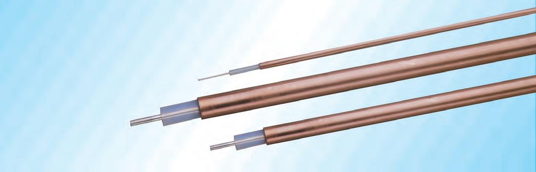
Coppersol employs a thin tubular copper outer conductor and solid PTFE dielectric which provides the lowest attenuation and highest shielding giving it significant performance advantages over flexible coax of similar size.
Coppersol was developed 30-40 years ago and was subsequently adopted by the military and MIL-C-17 specification sheets and QPL status were achieved.
Some of the key characteristics of Coppersol are:
Shielding Effectiveness – the highest achievable for any cable and is estimated at >165 db, well below measurable limits..
Small/Lightweight – much smaller and therefore lighter weight than flexible coax having similar electrical performance.
Phase Stable – the solid outer conductor minimizes electrical length change with temperature to substantially lower levels than flexible coax cables.
Low Loss – can achieve up to 50% less loss than flexible cable of the same size.
Attenuation Stability – impervious outer conductor prevents oxidation of the conductors thereby minimizing attenuation change vs. time.
Electrical Performance – has lowest VSWR and pulse reflection coefficient and exhibits very uniform characteristics to >20 GHz.
Corrosion Resistance – jacketing of the bare copper tube or plating with tin or silver is recommended when cable is deployed in a corrosive environment.
Formability – the solid copper tube enables the cable to be bent to any 3 dimensional configuration and have it retain its shape.
Connectors – standard inexpensive solder-on connectors are available from a variety of connector sources.
Coppersol Semirigid Coaxial Cables
(800)-TMS-COAX • www.timesmicrowave.com • (203)-949-8400 22
TMS Conductor Dielectric Shields Weight Impedance Capacitance Oper. Temp. Min, Bend Test Number inches inches inches lbs/foot ohms pF/foot Voltage Range Radius Freq. (mm) (mm) (mm) (kg/m) Vp(%) (pF/m) Cent. Cond Shield (s) kvrms F (C) in. (mm) CL-50086 SCCS PTFE BC Tube 0.0153 50+/-1.5 29.4 64.8 2.68 1.5 -40+194 0.125 0.5M17/133-RG405 0.0201 0.066 0.0865 20 (0.51) (1.68) (2.20) (0.023) 69.5 (96.5) (212.6) (8.86) (-40+125) (3.2) GHz CL-50141 SCCS PTFE BC Tube 0.0344 50+/-1 29.4 20.0 1.32 1.9 -40+194 0.250 0.5M17/130-RG402 0.0362 0.1175 0.141 20 (0.92) (2.98) (3.58) (0.051) 69.5 (96.5) (65.6) (4.3) (-40+125) (6.4) GHz CL-50250 SC PTFE BC Tube 0.105 50+/-0.5 29.4 2.6 0.45 3.0 -40+194 0.375 0.5M17/129-RG401 0.0641 0.209 0.250 20 (1.63) (5.31) (6.35) (0.156) 69.5 (96.5) (8.4) (1.5) (-40+125) (9.5) GHz DC Resistance ohms/1kft (/km)
• Low Passive Intermod
• High Temperature
• High Power
(800)-TMS-COAX • www.timesmicrowave.com • (203)-949-8400 23
Frequency (MHz) Frequency (MHz) 500 1,000 2,000 3,000 8,000 10,000 12,000 16,000 18,000 20,000 k1 k2 CL-50086 13.2 19.0 27.6 34 60 68 76 91 97 104 0.564 0.00120 CL-50142 7.7 11.3 16.6 21.0 38 44 49 59 64 69 0.318 0.00120 CL-50250 4.6 6.9 10.4 13.4 26 30 34 42 46 49 0.179 0.00120 Attenuation at Any Frequency = [ k1 x SQRT (Fmhz) ] + [ k2 x Fmhz ]; dB per 100 feet Attenuation vs. Frequency (Typical) 1000 100 10 1 100 1,000 10,000 100,000 Attenuation (db per 100 feet) CL-50086 CL-50141 CL-50250 Frequency (MHz) Frequency (MHz) 500 1,000 2,000 3,000 8,000 10,000 12,000 16,000 18,000 20,000 CL-50250 1024 685 449 347 179 152 133 107 97 90 CL-50141 592 403 271 213 115 99 87 71 65 60 CL-50086 174 120 82 65 36 31 28 23 21 20 Watts; Sea Level; Ambient +40C; VSWR 1:1; Outer Conductor +125C Power Handling vs. Frequency (Maximum) 10,000 1000 100 10 1 100 1,000 10,000 100,000 Power (watts) CL-50250 CL-50141 CL-50086
Coppersol® CLL
Low Loss Semirigid Coax

Features & Benefits
• Lower Loss than Standard Semi-rigid
• Excellent Shielding Effectiveness
• Low Passive Intermod (PIM)
• Stable Loss, Phase and VSWR
Coppersol-CLL employs a thin tubular copper outer conductor and low-density PTFE dielectric which provide the lowest loss and highest shielding giving it significant performance advantages over semirigid coax of similar size.
Coppersol-CLL was developed 25 years ago and have been widely adopted by the military OEM’s.
Some of the key characteristics of Coppersol-CLL are:
Shielding Effectiveness – the highest achievable for any cable and is estimated at > 165 dB, well below measurable limits.
Small/Lightweight – same size but lighter weight than standard CL semirigid coax.
Phase Stable – the solid outer conductor and low density PTFE minimizes electrical length change with temperature to yield 100 % improvement over
standard CL semirigid coax.
Low Loss – can achieve up to 30 % less loss than standard CL semirigid coax.
Attenuation Stability – impervious outer conductor prevents oxidation of the conductors thereby minimizing attenuation change vs time.
Power Handling – higher operating temperature provides 200% increase in power handling vs standard CL semirigid.
Corrosion Resistance – jacketing of the bare copper tube or plating with tin or silver is recommended when cable is deployed in a corrosive environment.
Formability – the solid copper tube enables the cable to be bent to any 3 dimensional configuration and have it retain its shape.
Connectors – are available from a variety of sources to fit Coppersol-CLL.
Coppersol CLL Low Loss Semirigid Coaxial Cables
(800)-TMS-COAX • www.timesmicrowave.com • (203)-949-8400 24
Loss Microwave Interconnect
• Low
Base Station Interconnect
• Wireless
TMS Conductor Dielectric Shields Weight Impedance Capacitance Oper. Temp. Min, Bend Test Number inches inches inches lbs/foot ohms pF/foot Voltage Range Radius Freq. (mm) (mm) (mm) (kg/m) Vp(%) (pF/m) Cent. Cond Shield (s) kvrms F (C) in. (mm) CLL-50086 SCCS LD PTFE BC Tube 0.0130 50+/-1.5 26.8 53.6 2.68 0.6 -85+482 0.25 0.50.022 0.066 0.0860 20 (0.56) (1.68) (2.18) (0.019) 76 (87.9) (175.9) (8.8) (-65+250) (6.4) GHz CLL-50141 SC LD PTFE BC Tube 0.0290 50+/-1 26.8 6.8 1.32 1.3 -85+482 0.50 0.50.039 0.1180 0.141 20 (0.99) (3.00) (3.58) (0.0431) 76 (87.9) (22.4) (4.3) (-65+250) (12.7) GHz CLL-50250 SC LD PTFE BC Tube 0.091 50+/-1 26.8 2.1 0.45 2.2 -85+482 2.0 0.50.0700 0.210 0.250 20 (1.78) (5.33) (6.35) (0.136) 76 (87.95) (7.0) (1.5) (-65+250) (50.8) GHz CLL-50375 SC LD PTFE BC Tube 0.187 50+/-1 26.8 0.83 0.365 3.0 -85+482 3.25 0.50.1120 0.335 0.375 12 (2.84) (8.51) (9.535) (0.279) 76 (87.9) (2.7) (1.2) (-65+250) (82.6) GHz Tinned and Silver Plated Outer Conductors Available on Request
DC Resistance ohms/1kft (/km)
• Low Passive Intermod
• High Temperature
• High Power
(800)-TMS-COAX • www.timesmicrowave.com • (203)-949-8400 25
Frequency (MHz) Frequency (MHz) 500 1,000 2,000 3,000 8,000 10,000 12,000 16,000 18,000 20,000 k1 k2 CLL-50086 11.8 16.8 23.9 29 48 54 60 69 74 78 0.525 0.00018 CLL-50141 6.7 9.5 13.5 16.6 28 31 34 40 43 45 0.293 0.00018 CLL-50250 3.8 5.4 7.8 9.6 16 18 20 24 25 27 0.165 0.00018 CLL-50375 2.4 3.5 5.0 6.2 11 12 14 - - - 0.104 0.00018 Attenuation at Any Frequency = [ k1 x SQRT (Fmhz) ] + [ k2 x Fmhz ]; dB per 100 feet Power Handling vs. Frequency (Maximum) 10,000 1,000 100 10 100 1,000 10,000 100,000 Power (watts) Frequency (MHz) Frequency (MHz) 500 1,000 2,000 3,000 8,000 10,000 12,000 16,000 18,000 20,000 CLL-50375 3633 2525 1743 1397 805 707 635 - -CLL-50250 1908 1332 925 745 436 384 347 294 274 257 CLL-50141 834 584 407 329 194 171 155 131 123 116 CCL-50086 363 254 177 143 84 74 67 56 53 50 Watts; Sea Level; Ambient +40C; VSWR 1:1; Outer Conductor +250C CLL-50375 CLL-50250 CLL-50141 CLL-50086 100 1,000 10,000 100,000 Attenuation vs. Frequency (Typical) 100 10 1 Attenuation (db per 100 feet) CLL-50086 CLL-50141 CLL-50250 CLL-50375
Mission Critical PERFORMANCE
EW System Interconnects from TIMES MICROWAVE SYSTEMS

Multi-Port Interconnects
•38999 size 8, 12; M8; P8; MMP Contacts
•Blind-Mating, ARINC, Rack & Panel, Custom Shells
•Easy Insertion/ Removal, Field Replaceable Contacts
•Rugged, Sealed, Extreme Environment Qualified
Vehicle Mounted/ Deployed Antenna
Feeder Cables
•Excellent Long-Term Electrical Performance
•Resists Harsh Treatment and Environments
•NBC Compliant Ruggedization Options
•Suited to COMM, COMMINT, IED, More
Military Low Smoke Cables
•Ideal for Shipboard, Vehicle, Manned Area Use
•Low Loss, Light Weight, Superior RF Shielding
•Fire Retardant (non-halogen), Flexible
•MIL-DTL-17H Qualified
Integrated Device Assemblies
•Flat, Equalized, Filtered, Attenuated, Amplified
•Platform-Independent System Design
•Dramatically Boosts System Performance
•Broadband Performance
PhaseTrack™ for Critical Phase Applications
•Superior Electrical Phase Stability (vs LD PTFE)
•<1.5 ppm/ °C
•TF4 Dielectric Technology (no PTFE “Knee”)
•Ruggedization Options Available
Blind Mate Antenna Solutions
•Convert Antennas to Blind Mate
•Improve Reliability, Maintainability and Serviceability
•Simplify Mission Equipment Role Changes
•Reduce Loss, Eliminate Cable Loop
SiO2 (Silicon Dioxide) Cable Assemblies
•Exceptional Phase Stability
•Temperature: -273°C to +600°C
•Hermetically Sealed to 10E-9
•Resistance to Harsh/Extreme Environments

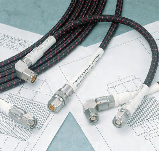
MilTech™ Microwave Transmission Lines
•Flexible, Hermetically Sealed Cables
•Low Loss to 20 dB/100 ft. at 18 GHz
•Replaceable Standard and Self-Locking Connectors
•Aircraft Qualified Worldwide
(800)-TMS-COAX • www.timesmicrowave.com • (203)-949-8400 26
M17
RG Cables
(800)-TMS-COAX • www.timesmicrowave.com • (203)-949-8400 27
and
MIL-C-17 and RG Coaxial Cable Reference Guide and Technical Information
MIL-C-17 COAXIAL CABLES
INTRODUCTION
MIL-C-17 is the government specification document used to standardize coaxial cables; it has been in use since the 1940’s. In the many revisions made to MIL-C-17 over the years, the familiar RG part numbers were superseded by M17 part numbers during the 1970s. The benefits of these more recent revisions are discussed under the following headlines. The most recent and therefore applicable revision to MIL-DTL-17 is Revision H.
Pages 29 through 39 contain a complete listing of all current M17 cables. For engineering reference, pages 45 through 61 contain the old RG tables. Attenuation and power handling characteristics tables are presented on pages 40 through 44.
BENEFITS IN USING MIL-C-17 COAXIAL CABLES
Revision E to MIL-C-17 was released in 1976 to better define the mechanical and electrical requirements for military coaxial cables. For 50-ohm cables, the most important changes were the addition of swept frequency measurements of both attenuation and structural return loss requirements (VSWR) to 22 different cables. Before this revision there were no VSWR requirements, and attenuation requirements were only given at two or three discrete frequencies. Other significant changes are described in the following paragraphs.
ADHESION REQUIREMENTS
MIL-C-17 specifications now contain the minimum and maximum adhesion requirements of the dielectric core to the center conductor. Prior to revision E, it was possible for a cable to have so little adhesion that the center conductor in shorter cables could be pulled out of the entire assembly during the stripping operation. Or there could be too much adhesion between the core and the conductor, causing the conductor to break before the dielectric core could be stripped off. With Revision E, a definite criterion has been specified.
DIMENSIONAL STABILITY
Revision E required that all cables be manufactured and tested to a specific maximum shrinkback allowance for the dielectric core and the jacket. Temperature extremes can cause shrinkback of the cable jacket which can create a poor termination.
ECCENTRICITY
Before Revision E was implemented, eccentricity requirements applied only to polyethylene dielectrics. Now eccentricity requirements have been identified for other kinds of dielectrics (e.g., PTFE). Cables that meet the eccentricity requirement facilitate the reliable assembly of connector parts and provide low VSWR ratios.
STRESS-CRACK RESISTANCE
MIL-C-17 now requires a stress-crack resistance test on all FEP (fluorinated ethylene propylene) and PFA (perfluoroalkoxy) jacketed cables. This test identifies cables with previously undetected residual stress that could result in jacket cracking.
CONTAMINATION
Although earlier MIL-C-17 specifications allowed the use of some Type I PVC (polyvinylchloride) for jackets, Revision F has completely replaced it with Type II PVC, a non-contaminating compound. The plasticizers in Type I PVC can penetrate the braided shield and migrate into the polyethylene dielectric core, causing a large increase in the dielectric loss portion of attenuation, especially at frequencies above 1 GHz. It should be noted that a cable with a type I PVC jacket can affect other cables in close contact, even if the other cables all have Type IIa jackets.
ATTENUATION AND STRUCTURAL RETURN LOSS
MIL-C-17 specifications require that attenuation and structural return loss (VSWR) be completely tested by sweeping 22 different 50-ohm cables over the frequency band for which their use is recommended. Variance in materials or in the manufacturing process can cause
periodic discontinuities along a length of coaxial cable which can introduce resonance peaks (spikes). These spikes occur when the discontinuities or changes in electrical characteristics are periodic and at half-wave distances.
When impedance changes occur periodically, there are frequencies in which all of the reflections are in phase, resulting in a large reflected signal or VSWR that is out of proportion to the normal VSWR of the cables and its connectors. Periodic reflections can also cause substantial increase in attenuation at the resonance peaks. In the past, it was very unusual to detect these narrow band, high attenuation spikes when cables were tested for attenuation using the older MIL-C-17D discrete frequency test procedure (generally at 400 MHz and 3 GHz, and also at 10 GHz for RG-214).
Now, however, M17/75-RG214 has continuous swept maximum VSWR and attenuation requirements from 50 MHz to 11 GHz. The maximum VSWR is 1.15:1 (23 dB SRL) at 100 MHz increasing to a maximum of 1.33:1 (17 dB structural return loss) at 11 GHz. The maximum attenuation is 1.7 dB/100 feet at 50 MHz increasing to 60 dB/100 feet at 11 GHz.
Coaxial cables that do not require “full band” swept frequency performance can be procured under separate part numbers in an unswept version. The specifications sheets for these unswept cables recommend that they not be used above 400 MHz. The user must decide which cables will best suit the situation based on cost, application and potential for system growth and improvements.
CABLE DESIGNATIONS
Cables that are manufactured to MIL-C-17 specifications no longer carry the RG designation. For example, RG-214 has been replaced by M17/75-RG214. In the future, any new cable design will be designated by an M17 part number only. In addition to the M17 number, all cables are marked with the manufacturer’s name and government identification number, for example, “M17/75-RG214, MIL-C-17, Times Microwave Systems, 68999 AA-3409” Cables that are not marked with this information are not qualified and there is no guarantee of their performance.
MIL-C-17 QPL LISTING
Only qualified cables should be used for military contracts. All manufacturers of MIL-C-17 cables must obtain qualification approval for their cables. The qualified products are then listed in QPL-17 which is updated periodically throughout the year. Please note that all RG numbered cables have been cancelled from MIL-C-17 and only cables with part numbers starting “MIL/17” should be used for new military contracts. Since there is no longer any control of “RG” specifications, many cables on the market with RG designations may be completely different in construction and performance. The RG tables listed in this catalog, when supplied by Times, are manufactured in accordance with the original specifications sheet released by the military.
SPECIAL DESIGNS
Although MIL-C-17 covers a broad range of cable types, Times can also provide technical assistance in designing specialized cables to meet specific system parameters that cannot be met with existing MILC-17 cables. Please contact our Marketing Department for assistance with your specialized need.
(800)-TMS-COAX • www.timesmicrowave.com • (203)-949-8400 28
M17/MIL-C-17 Coaxial Cable Specifications
(800)-TMS-COAX • www.timesmicrowave.com • (203)-949-8400 29
M17 M17 TMS Conductor Dielectric Shields Jacket Armor Weight Impedance Capacitance Max Oper. Temp. M17 Part QPL Part inches inches inches inches inches lb/ft ohms pF/ft Voltage Range Test Comments No. No. (mm) (mm) (mm) (mm) (mm) (kg/m) Vp (%) (pF/m) vrms F (C) Frequency M17/2-RG6 17-663-83 AA-3810 CCS PE 34SC-34BC PVC-IIA NA 0.082 75 +/-3 20.6 3,000 -40 +185 3 GHz Use M17/180-00001 0.0285 0.185 0.243 0.332 Unswept LS/LT Jacket (0.724) (4.70) (6.17) (8.43) (0.122) 66 (67.6) (-40 +85) M17/6-RG11 17-100-79 AA-3811 TC 7/.0159” PE 33BC PVC-IIA NA 0.098 75 +/-3 20.8 5,000 -40 +185 1GHz Use M17/181-00001 0.0477 0.285 0.318 0.405 Unswept LS/LT Jacket (1.21) (7.24) (8.08) (10.29) (0.146) 66 (67.6) (-40 +85) M 17/6-RG12 17-100-79 AA-3812 TC 7/.0159” PE 33BC PVC-IIA Alum.Braid 0.144 75 +/-3 20.6 5,000 -40+185 1 GHz Use M17/181-00002 0.0477 0.285 0.318 0.405 0.463 Unswept LS/LT Jacket (1.21) (7.24) (8.08) (10.29) (11.76) (0.200) 66 (67.6) (-40+85) M17/15-RG22 17-793-77 AA-3395 2-BC7/ .0152” PE 34TC:34TC PVC-IIA NA 0.134 95 +/- 5 16.0 1.000 -40+185 200 MHz Use M17/182-00001 0.0456 0.285 0.343 0.420 Unswept LS/LT Jacket (1.16) (7.24) (8.71) (10.67) (0.200) 66 (52.5) (-40 +85) M17/15-RG111 17-793-77 AA-3396 2-BC 7/.0152” PE 34TC:34TC PVC-IIA Alum. Braid 0.161 95 +/- 5 16.0 1,000 -40 +185 200MHz Use M17/182-00002 0.0456 0.285 0.343 0.420 0.478 Unswept LS/LT Jacket (1.16) (7.24) (8.71) (10.67) (12.14) (0.240) 66 (52.5) (-40 +85) M17/16-RG23 No AA-5160 2-BC 7/.0285” PE: 2 cores 34BC:34BC PVC-IIA NA 0.530 125 +/- 5 12.0 7,000 -40 +185 400 MHz Inactive for new design QPL’d 0.0855 0.380 .438 x .847 .650 x .945 Unswept Source (2.17) (9.65) (11.1 x 21.5) (16.5 x 24.0) (0.789) 66 (39.4) (-40 +85) M17/16-RG24 No AA-5161 2-BC 7/.0285” PE: 2 cores 34BC:34BC PVC-IIA Alum. Braid 0.730 125 +/-5 12.0 7,000 -40+185 400 MHz Inactive for new design QPL’d 0.0855 0.380 .438 x .847 .650 x .945 .708 x 1.003 Unswept Source (2.17) (9.65) (11.1 x 21.5) (16.5 x 24.0) (18.0 x 25.5) (1.087) 66 (39.4) (-40 +85) M17/19-RG25 No AA-5124 TC 19/.0117” Rubber-E 34TC-34TC Rubber-IV NA 0.225 48 +/-4 50.0 10,000 -67 +194 1 MHz Triaxial Pulse Cable QPL’d 0.0585 0.288 0.382 0.505 Unswept Source (1.49) (7.32) (9.70) (12.83) (0.335) 42 (164.1) (-55 +90) M17/21-RG26 No AA-5125 TC 19/.0117” Rubber-E 34TC Rubber-IV Alum. Braid 0.210 48 +/-4 50.0 10,000 -40 +185 1 MHz Coaxial Pulse Cable QPL’d 0.0585 0.288 0.317 0.425 0.505 Unswept Armored Source (1.49) (7.32) (8.05) (10.80) (12.83) (0.313) 42 (164.1) (-40 +85) M17/22-RG27 No AA-5163 TC 19/.0185” Rubber-D 34TC Rubber-IV Alum. Braid 0.330 48 +/-4 50.0 15,000 -40 +185 1 MHz Coaxial Pulse Cable QPL’d 0.0925 0.455 0.484 0.595 0.670 Unswept Armored Source (2.35) (11.56) (12.29) (15.11) (17.02) (0.492) 42 (164.1) (-40 +85) M17/22-00001 No AA-5162 TC 19/.0185” Rubber-D 34TC Rubber-IV NA 0.330 48 +/-4 50.0 15,000 -40 +185 1 MHz Coaxial Pulse Cable QPL’d 0.0925 0.455 0.484 0.595 Unswept Source (2.35) (11.56) (15.11) (15.11) (0.492) 42 (164.1) (-40 +85) M17/23-RG28 No AA-5164 TC 19/.0185” Rubber-D 34TC:34GS Rubber-IV NA 0.400 48 +/-4 50.0 15,000 -40 +185 1 MHz Triaxial Pulse Cable QPL’d 0.0925 0.455 0.559 0.735 Unswept Source (2.35) (11.58) (14.20) (18.67) (164.1) 42 (164.1) (-40 +85) M17/24-RG34 No AA-3813 TC 7/.0249” PE 33BC PVC-IIA NA 0.231 75 +/-3 22.0 6,500 -40+185 1 GHz QPL’d 0.0747 0.460 0.493 0.630 Unswept Source (1.90) (11.68) (12.52) (16.00) (0.344) 66 (72.2) (-40+85) M17/28-RG58 17-304-83 AA-3397 TC 19/.0072” PE 36TC PVC-IIA NA 0.026 50 +/-2 30.8 1,900 -40+185 .05 to 1 GHz Use: M17/183-00001 0.0355 0.116 0.139 0.195 Swept LS/LT Jacket (0.090) (2.95) (3.53) (4.95) (0.039) 66 (101.1) (-40+85) M17/29-RG59 17-102-79 AA-3797 CCS PE 34BC PVC-IIA NA 0.035 75 +/-3 20.6 2,300 -40+185 1 GHz Use: M17/184-00001 0.0226 0.146 0.175 0.242 Unswept LS/LT Jacket (0.57) (3.71) (4.45) (6.15) (0.052) 66 (67.6) (-40 +85) M17/30-RG62 17-795-77 AA-3398 CCS Airspaced PE 34BC PVC-IIA NA 0.038 93 +/-5 13.5 1,000 -40 +176 1 GHz Use: M17/185-00001 0.0253 0.146 0.175 0.242 Unswept LS/LT Jacket (0.64) (3.71) (4.45) (6.15) (0.057) 81 (44.3) (-40 +80) M17/31-RG63 17-103-79 AA-3815 CCS Airspaced PE 33BC PVC-IIA NA 0.138 125 +/-6 11.0 750 -40 +176 1 GHz Use: M17/218-00001 0.0253 0.285 0.318 0.405 Unswept LS/LT Jacket (0.64) (7.24) (8.08) (10.29) (0.206) 86 (36.1) (-40 +80) M17/31-RG79 17-103-79 AA-3816 CCS Airspaced PE 33BC PVC-IIA Alum. Braid 0.088 125 +/-5 10.0 1,000 -40 +175 1GHz Use: M17/218-00002 0.0253 0.285 0.318 0.405 0.475 Unswept LS/LT Jacket (0.64) (7.24) (8.08) (10.29) (12.07) (0.131) 81 (32.8) (-40 +80) M17/33-RG64 No AA-5126 TC 19/.0117” Rubber-E 34TC:34TC Rubber-IV NA 0.220 48 +/-4 55.0 10,000 -40 +185 1 MHz Coaxial Pulse Cable QLP’d 0.0585 0.288 0.346 0.450 Unswept Source (1.49) (7.32) (8.79) (11.68) (0.328) 42 (180.5) (-40 +85) M17/34-RG65 No AA-5165 .008” MW Helix PE 33BC PVC-IIA NA 0.110 950 +/-50 48.0 1,500 -40 +176 5 MHz Coaxial Delay Line QLP’d 0.1280 0.285 0.318 0.405 Unswept 0.15 uSec/foot Source (3.25) (7.24) (8.08) (10.29) (0.164) 2 (157.5) (-40 +85) M17/45-RG108 17-796-77 AA-3399 2:TC 7/.0126” PE (2 cores) 36TC PVC-IIA NA 0.035 78 +/-7 19.6 1,000 -40 +185 10 MHz Use: M17/186-00001 0.0378 0.079 0.181 0.235 Unswept LS/LT Jacket (0.96) (2.01) (4.60) (5.97) (0.052) 68 (64.3) (-40 +85) M17/47-RG114 Non- AA-3817 CCS Airspaced PE 34BC PVC-IIA NA 0.089 185 +/-10 6.5 1,000 -40 -176 1 GHz Use: M17/208-00001 QPL’d 0.007 0.285 0.314 0.405 Unswept LS/LT Jacket (0.18) (7.24) (7.98) (10.29) (1.33) 85 (21.3) (-40 +80)
M17/MIL-C-17 Coaxial Cable Specifications
(800)-TMS-COAX • www.timesmicrowave.com • (203)-949-8400 30 M17/52-RG119 17-749-85 AA-3818 BC PTFE 33BC:34BC FG Braid-V NA 0.228 50 +/-2 29.4 6,000 -67 +392 .05 - 1 GHz High Power Coax 0.1019 0.332 0.394 0.465 Swept (2.59) (8.43) (10.01) (11.81) (0.340) 69.5 (96.5) (-55 +200) M17/52-RG120 17-749-85 AA-3819 BC PTFE 33BC:34BC FG Braid-V Alum Braid 0.286 50 +/-2 29.4 6,000 -67 +392 .05 - 1GHz Armored 0.1019 0.332 0.394 0.465 0.525 Swept M17/52-RG119 (2.59) (8.43) (10.01) (11.81) (13.34) (0.426) 69.5 (96.5) (-55 +200) M17/52-00001 No NA BC PTFE 33SC:33SC FG Braid-V NA 0.228 50 +/-2 29.4 6,000 -67 +392 .05 - 3GHz High Frequency QPL’d 0.1019 0.332 0.394 0.465 Swept M17/52-RG119 Source (2.59) (8.43) (10.01) (11.81) (0.340) 69.5 (96.5) (-55 +200) M17/54-RG122 17-305-83 AA-3400 TC 27/.005” PE 36TC PVC-IIA NA 0.021 50 +/-2 30.8 1,900 -40 +185 .05 - 1 GHz Use M17/187-00001 0.0308 0.096 0.119 0.160 Swept LS/LT Jacket (0.78) (2.44) (3.02) (4.06) (0.031) 66 (101.1) (-40 +85) M17/56-RG130 No AA-5166 2: BC 7/.0285” PE 30TC PVC-IIA NA 0.300 95 +/-5 16.3 3,000 -40 +185 200 MHz Balanced QPL’d 0.0855 0.472 0.518 0.625 UnSwept Shielded Line Source (2.17) (11.99) (13.16) (15.88) (0.447) 66 (53.5) (-40 +85) M17/56-RG131 No AA-5187 2:BC 7/.0285” PE 30TC PVC-IIA Alum. Braid 0.400 95 +/5 16.3 3,000 -40 +185 200 MHz Armored QPL’d 0.0855 0.472 0.518 0.625 0.710 UnSwept M17/56-RG130 Source (2.17) (11.99) (13.16) (15.88) (18.03) (0.596) 66 (53.5) (-40 +85) M17/60-RG142 17-664-83 AA-3401 SCCS PTFE 36SC: 36SC FEP-IX NA 0.043 50 +/-2 29.4 1,900 -67 +392 .05 - 8 GHz 50 ohm Low Loss 0.037 0.116 0.162 0.195 Swept High Temperature (0.94) (2.95) (4.11) (4.95) (0.064) 69.5 (96.5) (-55 +200) Coax M17/62-RG144 17-750-85 AA-3820 SCCS 7/.0175” PTFE 34SC FG Braided-V NA 0.140 75 +/-3 19.5 5,000 -67 +392 3 GHz 75 ohm Low Loss 0.0525 0.285 0.314 0.410 UnSwept High Temperature (1.33) (7.24) (7.98) (10.41) (0.209) 69.5 (64.0) (-55 +200) Coax M17/64-RG35 No AA-3822 BC PE 30BC PVC-IIA Alum.Braid 0.545 75 +/- 3 20.6 10,000 -40 +185 1 GHz Armored QPL’d 0.1045 0.680 0.726 0.870 0.945 UnSwept M17/209-00001 Source (2.65) (17.27) (18.44) (22.10) (24.00) (0.812) 66 (67.6) (-40 +85) M17/64-RG164 No AA-3821 BC PE 30BC PVC-IIA NA 0.505 75 +/- 3 20.6 10,000 -40 +185 1 GHz Use: M17/209-0001 QPL’d 0.1045 0.680 0.726 0.870 UnSwept LS/LT Jacket Source (2.65) (17.27) (18.44) (22.10) (0.752) 66 (67.6) (-40 +185) M17/65-RG165 17-598-81 AA-3402 SC 7/.0315” PTFE 34SC FG Braid-V NA 0.142 50 +/- 2 29.4 2,500 -67 +482 0.05 - 3 GHz 0.094 0.285 0.314 0.410 Swept (2.39) (7.24) (7.98) (10.41) (0.212) 69.5 (96.5) (-55 +250) M17/65-RG166 17-598-81 AA-3403 SC 7/.0315” PTFE 34SC FG Braid-V Alum.Braid 0.189 50 +/- 2 29.4 2,500 -67 +482 0.05 - 3 GHz Armored 0.094 0.285 0.314 0.410 0.470 Swept M17/65-RG165 (2.39) (7.24) (7.98) (10.41) (11.94) (0.282) 69.5 (96.5) (55 +250) M17/67-RG177 17-1102-85 AA-3404 BC PE 34SC: 34SC PVC-IIA NA 0.520 50 +/- 2 30.8 11,000 -40 +185 0.05 - 3 GHz Use: M17/210-00001 0.195 0.680 0.738 0.895 Swept LS/LT Jacket (4.95) (17.27) (18.75) (22.73) (0.775) 66 (101.1) (-40 +85) M17/72-RG211 No AA-3405 BC PTFE 32BC FG Braid-V NA 0.516 50 +/- 2 29.4 7,000 -67 +482 0.05 - 3 GHz QPL’d 0.192 0.620 0.657 0.730 Swept Source (4.88) (15.75) (16.69) (18.54) (0.769) 69.5 (96.5) (-55 +250) M17/73-RG212 17-1104-85 AA-3406 SC PE 34SC:34SC PVC-IIA NA 0.089 50 +/- 2 30.8 3,000 -40 +185 0.05 - 3 GHz Use:M17/188-00001 0.0556 0.185 0.243 0.332 Swept LS/LT Jacket (1.41) (4.70) (6.17) (8.43) (0.133) 66 (101.1) (-40 +85) M17/74-RG213 17-804-77 AA-3408 BC 7/.0296” PE 33BC PVC-IIA NA 0.111 50 +/- 2 30.8 5,000 -40 +185 0.05 - 1 GHz Use M/17189-00001 0.0888 0.285 0.318 0.405 Swept LS/LT Jacket (2.26) (7.24) (8.08) (10.29) (0.165) 66 (101.1) (-40 +85) M17/74-RG215 17-804-77 AA-3407 BC 7/.0296” PE 33BC PVC-IIA Alum.Braid 0.138 50 +/- 2 30.8 5,000 -40 +185 0.05 - 11GHz Use M17/189-00002 0.0888 0.285 0.318 0.405 0.475 Swept LS/LT Jacket (2.26) (7.24) (8.08) (10.29) (12.07) (0.206) 66 (101.1) (-40 +85) M17/75-RG214 17-804-77 AA-3409 SC 7/.0296” PE 34SC:34SC PVC-IIA NA 0.130 50 +/- 2 30.8 5,000 -40 +185 0.05 - 11GHz Use M17/190-00001 0.0888 0.285 0.343 0.425 Swept LS/LT Jacket (2.26) (7.24) (8.71) (10.80) (0.194) 66 (101.1) (-40 +85) M17/75-RG365 17-984-85 AA-4761 SC 7/.0296” PE 34SC:34SC TPE NA 0.130 50 +/-2 30.8 5,000 -67 +185 0.05 - 11GHz 0.0888 0.285 0.343 0.425 Swept (2.26) (7.24) (8.71) (10.80) (0.194) 66 (101.1) (-55 +85) M17/77-RG216 17-108-79 AA-3823 TC 7/.0159” PE 34BC:34BC PVC-IIA NA 0.124 75 +/-3 20.6 5,000 -40 +185 3 GHz Use M17/191-00001 0.0477 0.285 0.343 0.425 UnSwept LS/LT Jacket (1.21) (7.24) (8.71) (10.80) (0.185) 66 (67.6) (-40 +85) M17/78-RG217 17-1102-85 AA-3410 BC PE 33BC:33BC PVC-IIA NA 0.225 50 +/-2 30.8 7,000 -40 +185 0.05 - 3GHz Use M17-192-00001 0.106 0.370 0.436 0.545 Swept LS/LT Jacket (2.69) (9.40) (11.07) (13.84) (0.335) 66 (101.1) (-40 +85)
M17 M17 TMS Conductor Dielectric Shields Jacket Armor Weight Impedance Capacitance Max Oper. Temp. M17 Part QPL Part inches inches inches inches inches lb/ft ohms pF/ft Voltage Range Test Comments No. No. (mm) (mm) (mm) (mm) (mm) (kg/m) Vp (%) (pF/m) vrms F (C) Frequency
M17/MIL-C-17 Coaxial Cable Specifications
(800)-TMS-COAX • www.timesmicrowave.com • (203)-949-8400 31 M17/78-00001 17-1102-85 AA-8212 BC PE 33BC:33BC PVC-IIA NA 0.225 50 +/-2 30.8 7,000 -40 +176 0.05 - 3GHz Temperature-cycled 0.106 0.370 0.436 0.545 Swept M17/78-RG217 (2.69) (9.40) (12.07) (13.84) (0.335) 66 (101.1) (-40 +85) M17/79-RG218 17-1102-85 AA-3411 BC PE 30BC PVC-IIA NA 0.510 50 +/-2 30.8 11,000 -40 +185 0.05 - 1GHz Use M17/193-00001 0.195 0.680 0.726 0.870 Swept LS/LT Jacket (4.95) (17.27) (18.44) (22.10) (0.760) 66 (101.1) (-40 +85) M17/79-RG219 17-1102-85 AA-3412 BC PE 30BC PVC-IIA Alum.Braid 0.550 50 +/-2 30.8 11,000 -40 +185 0.05 - 1GHz Use M17/193-00002 0.195 0.680 0.726 0.870 0.945 Swept LS/LT Jacket (4.95) (17.27) (18.44) (22.10) (24.00) (0.819) 66 (101.1) (-40 +85) M17/81-00001 17-354-88 AA-6002 BC PE 30BC PVC-IIA NA 0.820 50 +/-2 30.8 14,000 -40 +185 1 GHz 0.260 0.910 0.956 1.120 UnSwept (6.60) (23.11) (24.28) (28.45) (1.221) 66 (101.1) (-40 +85) M17/81-00002 17-354-88 AA-6003 BC PE 30BC PVC-IIA Alum.Braid 0.880 50 +/-2 30.8 14,000 -40 +185 1 GHz Armored 0.260 0.910 0.956 1.120 1.195 UnSwept M17/81-00001 (6.60) (23.11) (24.28) (28.45) (30.35) (1.311) 66 (101.1) (-40 +85) M17/84-RG223 17-303-83 AA-3413 SC PE 36SC:36SC PVC-IIA NA 0.041 50 +/-2 30.8 1,900 -40 +185 .04-12.4 GHz Use M17/194-00001 0.035 0.116 0.162 0.212 Swept LS/LT Jacket (0.89) (2.95) (4.11) (5.38) (0.061) 66 (101.1) (-40 +85) M17/86-00001 17-598-81 AA-5077 SC 7/.0312” PTFE 34SC:34SC FG Braid-V NA 0.195 50 +/-2 29.4 5,000 -67 +392 400 MHz 0.0936 0.285 0.343 0.430 UnSwept (2.38) (7.24) (8.71) (10.92) (0.290) 69.5 (96.5) (-55 +200) M17/86-00002 17-598-81 AA-5078 SC 7/.0312” PTFE 34SC:34SC FG Braid-V Alum.Braid 0.222 50 +/-2 29.4 5,000 -67 +392 400 MHz Armored 0.0936 0.285 0.343 0.430 0.490 UnSwept M17/86-00001 (2.38) (7.24) (8.71) (10.92) (12.45) (0.331) 69.5 (96.5) (-55 +200) M17/87-00001 17-355-88 AA-5168 SC 19/.0254” Taped PTFE 34BC:34SC FG Braid-V NA 0.448 50 +/-2 29.0 7,000 -67 +392 400 MHz 0.127 0.370 0.428 0.500 UnSwept (3.23) (9.40) (5.03) (12.70) (0.667) 71 (95.1) (-55 +200) M17/90-RG71 17-280-83 AA-4444 CCS Air-space PE 34BC:36TC PE-IIIA NA 0.050 93 +/-5 13.5 1,000 -67 +185 1GHz Use M17/195-00001 0.0253 0.146 0.198 0.245 UnSwept LS/LT Jacket (0.54) (3.71) (5.03) (6.22) (0.074) 81 (44.3) (-55 +85) M17/92-RG115 17-598-81 AA-3824 SC 7/.0280” Taped PTFE 34SC:34SC FG Braid-V NA 0.185 50 +/- 2 29.0 5,000 -67 +392 .05-12.4 GHz 0.084 0.255 0.313 0.415 Swept (2.13) (6.48) (7.95) (10.54) (0.276) 71 (95.1) (-55 +200) M17/92-00001 17-598-81 AA-5308 SC 7/.0280” Taped PTFE 34SC:34SC FEP-IX NA 0.185 50 +/- 2 29.0 5,000 -67 +392 .05-12.4 GHz 0.084 0.255 0.313 0.344 Swept (2.13) (6.48) (7.95) (8.74) (0.276) 71 (95.1) (-55 +200) M17/93-RG178 17-666-83 AA-3414 SCCS 7/.0040” PTFE 38SC FEP-IX NA 0.006 50 +/- 2 29.4 1,000 -67 +392 .05-3 GHz 0.012 0.033 0.051 0.071 Swept (0.30) (0.84) (1.30) (1.80) (0.009) 69.5 (96.5) (-55 +200) M17/93-00001 17-867-84 AA-4762 SCCS 7/.0040” PTFE 38SC PFA-XIII NA 0.006 50 +/- 2 29.4 1,000 -67 +446 .05-3 GHz 0.012 0.033 0.051 0.071 Swept (0.30) (0.84) (1.30) (1.80) (0.009) 69.5 (96.5) (-55 +230) M17/94-RG179 17-809-77 AA-3415 SCCS 7/.0040” PTFE 38SC FEP-IX NA 0.010 75 +/- 3 19.5 1,200 -67 +392 3 GHz 0.012 0.063 0.081 0.100 UnSwept (0.30) (1.60) (2.06) (2.54) (0.015) 69.5 (64.0) (-55 +200) M17/95-RG180 17-810-77 AA-3416 SCCS 7/.0040” PTFE 38SC FEP-IX NA 0.0198 95 +/-5 15.4 1,500 -67 +392 3 GHz 0.012 0.102 0.120 0.141 UnSwept (0.30) (2.59) (3.05) (3.58) (0.029) 69.5 (50.5) (-55 +200) M17/97-RG210 17-668-83 AA-4763 SCCS Air-space 34SC FG Braid-V NA 0.050 93 +/- 5 13.5 1,000 -67 +392 3 GHz 0.0253 PTFE 0.175 0.242 UnSwept (0.64) 0.146 (3.71) (4.45) (6.15) (0.074) 85 (44.3) (-55 +200) M17/100-RG133 No NA BC PE 33BC PVC-IIA NA 0.095 95 +/- 5 16.3 5,000 -40 +185 1 GHz QPL’d 0.0253 0.285 0.318 0.405 UnSwept Source (0.64) (7.24) (8.08) (10.29) (0.142) 66 (53.5) (-40 +85) M17/109-RG301 No NA HR 7/.0203” PTFE 36HR FEP-IX NA 0.056 50 +/- 2 29.4 3,000 -67 +392 3 GHz QPL’d 0.0609 0.185 0.208 0.245 UnSwept Source (1.55) (4.70) (5.28) (6.22) (0.083) 69.5 (96.5) (-55 +200) M17/110-RG302 17-425-84 AA-3826 SCCS PTFE 36SC FEP-IX NA 0.040 75 +/- 3 19.5 2,300 -67 +392 3 GHz 0.0253 0.146 0.169 0.202 UnSwept (0.64) (3.71) (4.29) (5.13) (0.060) 69.5 (64.0) (-55 +200) M17/111-RG303 17-811-77 AA-3417 SCCS PTFE 36SC FEP-IX NA 0.031 50 +/- 2 29.4 1,900 -67 +392 0.05-3 GHz 0.0370 0.116 0.139 0.170 Swept (0.94) (2.95) (3.53) (4.32) (0.046) 69.5 (96.5) (-55 +200)
M17 M17 TMS Conductor Dielectric Shields Jacket Armor Weight Impedance Capacitance Max Oper. Temp. M17 Part QPL Part inches inches inches inches inches lb/ft ohms pF/ft Voltage Range Test Comments No. No. (mm) (mm) (mm) (mm) (mm) (kg/m) Vp (%) (pF/m) vrms F (C) Frequency
M17/MIL-C-17 Coaxial Cable Specifications
(800)-TMS-COAX • www.timesmicrowave.com • (203)-949-8400 32
M17 M17 TMS Conductor Dielectric Shields Jacket Armor Weight Impedance Capacitance Max Oper. Temp. M17 Part QPL Part inches inches inches inches inches lb/ft ohms pF/ft Voltage Range Test Comments No. No. (mm) (mm) (mm) (mm) (mm) (kg/m) Vp (%) (pF/m) vrms F (C) Frequency M17/112-RG304 17-474-86 AA-5130 SCCS PTFE 34SC:34SC FEP-IX NA 0.094 50 +/- 2 29.4 3,000 -67 +392 0.05-8 GHz 0.0590 0.185 0.243 0.280 Swept (1.50) (4.70) (6.17) (7.11) (0.140) 69.5 (96.5) (-55 +200) M17/113-RG316 17-812-77 AA-3418 SCCS 7/.0067” PTFE 38SC FEP-IX NA 0.012 50 +/- 2 29.4 1,200 -67 +392 0.05-3 GHz 0.0201 0.060 0.078 0.098 Swept (0.51) (1.52) (1.98) (2.49) (0.018) 69.5 (96.5) (-55 +200) M17/116-RG307 17-482-84 AA-4346 SC 19/.0058” Foam PE 34SC- PE-IIIA NA 0.080 75 +/- 3 16.9 1,000 -67 +185 1 GHz 0.0290 0.146 PUR-34SC 0.265 UnSwept (0.74) (3.71) 0.234 (5.94) (6.73) (0.119) 81 (55.4) (-55 +80) M17/119-RG174 17-813-77 AA-3419 CCS 7/.0063” PE 38TC PVC-IIA NA 0.009 50 +/- 2 30.8 1,500 -40 +185 0.05-1 GHz Use M17/196-00001 0.0189 0.060 0.078 0.110 Swept LS/LT Jacket (0.48) (1.52) (1.98) (2.79) (0.013) 66 (101.1) (-40 +85) M17/124-RG328 No NA TC Braid Rubber H,J,H 30TC: Neoprene NA 1.600 25 +/- 2 85.0 15,000 -67 +185 1 GHz QPL’d 0.4850 1.065 33GS:30TC 1.460 UnSwept Source (12.32) (27.05) 1.251 (31.78) (37.08) (2.383) 48 (278.9) (-55 +85) M17/125-RG329 No NA TC19/.0117” Rubber H,J,H 30TC:33GS:30TC Neoprene NA 0.353 50 +/- 2 50.0 15,000 -67 +194 1 GHz QPL’d 0.0585 0.380 0.571 0.700 UnSwept Source (1.49) (9.65) (14.50) (17.78) (0.526) 43 (164.1) (-55 +90) M17/126-RG391 17-670-83 AA-4464 TC 7/.0159” CPE & PE 34TC PVC-IIA NA 0.100 72 +/-3 23.0 5,000 -40 +185 1 GHz Use: M17/211-00001 0.0477 0.295 0.324 0.405 UnSwept LS/LT Jacket (1.21) (7.49) (8.23) (10.29) (0.149) 64 (75.5) (-40 +85) M17/126-RG392 17-670-83 AA-4465 TC 7/.0159” CPE & PE 34TC PVC-IIA Alum.Braid 0.125 72 +/-3 23.0 5,000 -40 +185 1 GHz Armored 0.0477 0.295 0.324 0.405 0.475 UnSwept M17/211-00001 (1.21) (7.49) (8.23) (10.29) (12.07) (0.186) 64 (75.5) (-40 +85) M17/127-RG393 17-429-84 AA-3420 SC 7/.0312” PTFE 34SC:34SC FEP-IX NA 0.175 50 +/-2 29.4 5000 -67 +392 .05-11 GHz 0.094 0.285 0.343 0.390 Swept (2.39) (7.24) (8.71) (9.91) (0.261) 69.5 (96.5) (-55 +200) M17/128-RG400 17-671-83 AA-3827 SC 19/.0080” PTFE 36SC:36SC FEP-IX NA 0.050 50 +/-2 29.4 1,900 -67 +392 .05-12.4 GHz 0.0384 0.116 0.162 0.195 Swept (0.98) (2.95) (4.11) (4.95) (0.074) 69.5 (96.5) (-55 +200) M17/129-RG401 17-197-85 AA-5011 SC PTFE BC Tube None NA 0.105 50 +/-0.5 29.4 3,000 -40 +194 0.4-18 GHz 0.0641 0.209 0.250 Swept (1.63) (5.31) (6.35) (0.156) 69.5 (96.5) (-40 +90) M17/129-00001 17-197-85 AA-5012 SC PTFE TC Tube None 0.106 50 +/-0.5 29.4 3,000 -40 +194 0.4-18 GHz Tin Plated 0.0641 0.209 0.250 Swept M17/129-RG401 (1.63) (5.31) (6.35) (0.158) 69.5 (96.5) (-40 +90) M17/130-RG402 17-197-85 AA-5013 SCCS PTFE BC Tube None NA 0.0344 50 +/-2 29.4 1,900 -40 +257 0.5-20 GHz 0.0362 0.1175 0.141 Swept (0.92) (2.98) (3.58) (0.051) 69.5 (96.5) (-40 +125) M17/130-00001 17-197-85 AA-5014 SCCS PTFE TC Tube None NA 0.0351 50 +/-1 29.4 1,900 -40 +257 0.5-20 GHz Tin Plated 0.0362 0.1175 0.141 Swept M17/130-RG402 (0.92) (2.98) (3.58) (0.052) 69.5 (96.5) (-40 +125) M17/130-00002 17-197-85 AA-5015 SNCCS PTFE BC Tube None NA 0.0344 50 +/-1 29.4 1,900 -40 +257 0.5-20 GHz 0.0362 0.1175 0.141 Swept (0.92) (2.98) (3.58) (0.051) 69.5 (96.5) (-40 +125) M17/130-00003 17-197-85 AA-5016 SNCCS PTFE TC Tube None NA 0.0351 50 +/-1 29.4 1,900 -40 +257 0.5-20 GHz Tin Plated 0.0362 0.1175 0.141 Swept M17/130-00002 (0.92) (2.98) (3.58) (0.052) 69.5 (96.5) (-40 +125) M17130-00004 17-297-90 AA-5916 SCCS PTFE BC Tube None NA 0.0344 50 +/-1 29.4 1,900 -40 +257 0.5-20 GHz 0.0362 0.1175 0.141 Swept (0.92) (2.98) (3.58) (0.051) 69.5 (96.5) (-40 +125) M17/130-00005 17-297-90 AA-5917 SCCS PTFE TC Tube None NA 0.0351 50 +/-1 29.4 1,900 -40 +257 0.5-20 GHz Tin Plated 0.0362 0.1175 0.141 Swept M17/130-00004 (0.92) (2.98) (3.58) (0.052) 69.5 (96.5) (-40 +125) M17/130-00006 17-297-90 AA-5918 SNCCS PTFE BC Tube None NA 0.0344 50 +/-1 29.4 1,900 -40 +257 0.5-20 GHz 0.0362 0.1175 0.141 Swept (0.92) (2.98) (3.58) (0.051) 69.5 (96.5) (-40 +125) M17/130-00007 17-297-90 AA-5919 SNCCS PTFE TC Tube None NA 0.0351 50 +/- 1 29.4 1,900 -40 +257 0.5-20 GHz Tin Plated 0.0362 0.1175 0.141 Swept M17/130-00006 (0.92) (2.98) (3.58) (0.052) 69.5 (96.5) (-40 +125) M17/130-00008 Non- NA SCCS PTFE AL Tube None NA 0.0188 50 +/- 1 29.9 1,900 -40 +257 0.5-20 GHz QPL’d 0.0362 0.1175 0.141 Swept (0.92) (2.98) (3.58) (0.028) 69.5 (98.1) (-40 +125)
M17/MIL-C-17 Coaxial Cable Specifications
(800)-TMS-COAX • www.timesmicrowave.com • (203)-949-8400 33 M17/130-00009 Non- NA SCCS PTFE Tinned AL Tube None NA 0.0205 50 +/- 1 29.9 1,900 -40 +257 0.5-20 GHz Tin Plated QPL’d 0.0362 0.1175 0.141 Swept M17/130-00008 (0.92) (2.98) (3.58) (0.031) 69.5 (98.1) (-40 +125) M17/130-00010 No NA SNCCS PTFE AL Tube None NA 0.0188 50 +/- 1 29.9 1,900 -40 +257 0.5-20 GHz QPL’d 0.0362 0.1175 0.141 Swept Source (0.92) (2.98) (3.58) (0.028) 9.5 (98.1) (-40 +125) M17/130-00011 No NA SNCCS PTFE Tinned AL Tube None NA 0.0205 50 +/- 1 29.9 1,900 -40 +257 0.5-20 GHz Tin Plated QPL’d 0.0362 0.1175 0.141 Swept M17/130-00010 Source (0.92) (2.98) (3.58) (0.031) 69.5 (98.1) (-40 +125) M17/130-00012 Non- NA SCCS PTFE SC Tube None NA 0.0351 50 +/- 1 29.9 1,900 -40 +257 0.5-20 GHz Silver Plated QPL’d 0.0362 0.1175 0.141 Swept M17/130-00004 (0.92) (2.98) (3.58) (0.052) 69.5 (98.1) (-40 +125) M17/130-00013 No NA SNCCS PTFE SC Tube None NA 0.0351 50 +/- 1 29.9 1,900 -40 +257 0.5-20 GHz Silver Plated QPL’d 0.0362 0.1175 0.141 Swept M17/130-00006 Source (0.92) (2.98) (3.58) (0.052) 69.5 (98.1) (-40 +125) M17/130-00014 No NA SCCS PTFE TC Tube None NA 0.0351 50 +/- 1 29.9 1,900 -40 +257 0.5-20 GHz 90/10 Tin Plated QPL’d .0362 0.1175 0.141 300u” minimum Source (0.92) (2.98) (3.58) (0.052) 69.5 (98.1) (-40 +125) M17/130-00015 No NA SC PTFE TC Tube None NA 0.0351 50 +/- 1 29.9 1,900 -40 +257 0.5-20 GHz 90/10 Tin Plated QPL’d .0362 0.1175 0.141 300u” minimum Source (0.92) (2.98) (3.58) (0.052) 69.5 (98.1) (-40 +125) M17/131-RG403 17-244-90 AA-6511 SCCS 7/.004 PTFE 38SC-FEP-38SC FEP-IX NA 0.015 50 +/-2 29.4 1,000 -67 +392 0.05-10 GHz RG-178 Triax 0.0120 0.033 0.088 0.116 Swept (0.30) (0.84) (2.24) (2.95) (0.022) 69.5 (96.5) (-55 +200) M17/132-00001 17-245-90 AA-6512 SCCS 7/.004 PTFE 38SC FEP-IX NA 0.018 50 +/-2 30.4 1,000 -40 +392 1 GHz RG-178 Low Noise 0.0120 & CPT 0.054 0.071 UnSwept (0.30) 0.035 (0.91) (1.37) (1.80) (0.027) 68 (99.7) (-40 +200) M17/133-RG405 17-197-85 AA-5017 SCCS PTFE BC Tube None NA 0.0153 50 +/-1.5 29.4 1,500 -40 +257 0.5-20 GHz 0.0201 0.065 0.0865 Swept (0.51) (1.68) (2.20) (0.023) 69.5 (96.5) (-40 +125) M17/133-00001 17-197-85 AA-5018 SCCS PTFE TC Tube None NA 0.0158 50 +/-1.5 29.4 1,500 -40 +257 0.5-20GHz Tinplated 0.0201 0.066 0.0865 Swept M17/133-RG405 (0.51) (1.68) (2.20) (0.024) 69.5 (96.5) (-40 +125) M17/133-00002 17-298-90 AA-5019 SC PTFE BC Tube None NA 0.0152 50 +/-1.5 29.4 1,500 -40 +257 0.5-20GHz 0.0201 0.066 0.0865 Swept (0.51) (1.68) (2.20) (0.023) 69.5 (96.5) (-40 +125) M17/133-00003 17-298-90 AA-5020 SC PTFE TC Tube None NA 0.0157 50 +/-1.5 29.4 1,500 -40 +257 0.5-20GHz Tinplated 0.0201 0.066 0.0865 Swept M17/133-00002 (0.51) (1.68) (2.20) (0.023) 69.5 (96.5) (-40 +125) M17/133-00004 17-298-90 AA-5021 SNCCS PTFE BC Tube None NA 0.0154 50 +/-1.5 29.4 1,500 -40 +257 0.5-20 GHz 0.0201 0.066 0.0865 Swept (0.51) (1.68) (2.20) (0.023) 69.5 (96.5) (-40 +125) M17/133-00005 17-298-90 AA-5022 SNCCS PTFE TC Tube None NA 0.0159 50 +/-1.5 29.4 1,500 -40 +257 0.5-20 GHz Tinplated 0.0201 0.066 0.0865 Swept M17/133-00004 (0.51) (1.68) (2.20) (0.024) 69.5 (96.5) (-40 +125) M17-133-00006 17-298-90 AA-5920 SCCS PTFE BC Tube None NA 0.0153 50 +/-1.5 29.4 1,500 -40 +257 0.5-20 GHz 0.0201 0.066 0.0865 Swept (0.51) (1.68) (2.20) (0.023) 69.5 (96.5) (-40 +125) M17-133-00007 17-298-90 AA-5921 SCCS PTFE TC Tube None NA 0.0158 50 +/-1.5 29.4 1,500 -40 +257 0.5-20 GHz Tinplated 0.0201 0.066 0.0865 Swept M17/133-00006 (0.51) (1.68) (2.20) (0.024) 69.5 (96.5) (-40 +125) M17/133-00008 17-298-90 AA-5922 SC PTFE BC Tube None NA 0.0152 50 +/-1.5 29.4 1,500 -40 +257 0.5-20 GHz 0.0201 0.066 0.0865 Swept (0.51) (1.68) (2.20) (0.023) 69.5 (96.5) (-40 +125) M17/133-00009 17-298-90 AA-5923 SC PTFE TC Tube None NA 0.0157 50 +/-1.5 29.4 1,500 -40 +257 0.5-20 GHz Tinplated 0.0201 0.066 0.0865 Swept M17/133-00008 (0.51) (1.68) (2.20) (0.023) 69.5 (96.5) (-40 +125) M17/133-00010 17-298-90 AA-5924 SNCCS PTFE BC Tube None NA 0.0154 50 +/-1.5 29.4 1,500 -40 +257 0.5-20 GHz 0.0201 0.066 0.0865 Swept (0.51) (1.68) (2.20) (0.023) 69.5 (96.5) (-40 +125) M17/133-00011 17-298-90 AA-5925 SNCCS PTFE TC Tube None NA 0.0159 50 +/-1.5 29.4 1,500 -40 +257 0.5-20 GHz Tinplated 0.0202 0.066 0.0865 Swept M17/133-00010 (0.51) (1.68) (2.20) (0.024) 69.5 (96.5) (-40 +125)
M17 M17 TMS Conductor Dielectric Shields Jacket Armor Weight Impedance Capacitance Max Oper. Temp. M17 Part QPL Part inches inches inches inches inches lb/ft ohms pF/ft Voltage Range Test Comments No. No. (mm) (mm) (mm) (mm) (mm) (kg/m) Vp (%) (pF/m) vrms F (C) Frequency
M17/MIL-C-17 Coaxial Cable Specifications
(800)-TMS-COAX • www.timesmicrowave.com • (203)-949-8400 34
M17 M17 TMS Conductor Dielectric Shields Jacket Armor Weight Impedance Capacitance Max Oper. Temp. M17 Part QPL Part inches inches inches inches inches lb/ft ohms pF/ft Voltage Range Test Comments No. No. (mm) (mm) (mm) (mm) (mm) (kg/m) Vp (%) (pF/m) vrms F (C) Frequency M17/133-00012 Non- NA SCCS PTFE AL Tube None NA 0.0075 50 +/-1.5 29.9 1,500 -40 +257 0.5-20 GHz QPL’d 0.0201 0.066 0.066 Swept (0.51) (0.68) (2.20) (0.011) 69.5 (98.1) (-40 +125) M17/133-00013 Non- NA SCCS PTFE Tinned AL Tube None NA 0.008 50 +/-1.5 29.9 1,500 -40 +257 0.5-20 GHz Tinplated QPL’d 0.0201 0.066 0.0865 Swept M17/133-00012 (0.051) (1.68) (2.20) (0.012) 69.5 (98.1) (-40 +125) M17/133-00014 No NA SNCCS PTFE AL Tube None NA 0.0075 50 +/-1.5 29.9 1,500 -40 +257 0.5-20 GHz QPL’d 0.0201 0.066 0.0865 Swept Source (0.51) (1.68) (2.20) (0.011) 69.5 (98.1) (-40 +125) M17/133-00015 No NA SNCCS PTFE Tinned AL Tube None NA 0.008 50 +/-1.5 29.9 1,500 -40 +257 0.5-20 GHz Tinplated QPL’d 0.0201 0.066 0.0865 Swept M17/133-00014 Source (0.51) (1.68) (2.20) (0.012) 69.5 (98.1) (-40 +125) M17/133-00016 Non- NA SCCS PTFE SC Tube None NA 0.0158 50 +/-1.5 29.9 1,500 -40 +257 0.5-20 GHz Silver plated QLP’d 0.0201 0.066 0.0865 Swept M17/133-00006 (0.51) (1.68) (2.20) (0.024) 69.5 (98.1) (-40 +125) M17/133-00017 No NA SNCCS PTFE SC Tube None NA 0.0158 50 +/-1.5 29.9 1,500 -40 +257 0.5-20 GHz Silver plated QLP’d 0.0201 0.066 0.0865 Swept M17/133-00010 Source (0.51) (1.68) (2.20) (0.024) 69.5 (98.1) (-40 +125) M17/133-00018 No NA SC PTFE TC Tube NA NA .0157 50 +/-1.5 29.9 1,500 -40 +257 0.5-20 GHz 90/10 Tinplated QPL’d .0201 0.066 .0865 Swept 300u” (minimum) Source (0.51) (1.68) (2.20) (.023) 69.5 (98.1) (-40 +125) M17/134-00001 17-952-85 AA-5411 SC PE 36SC-PE-36SC PE-IIIA NA 0.045 50 +/-2 30.8 1,900 -40 +158 .05-3 GHz Water blocked 0.033 0.116 0.198 0.245 Swept Triax (0.84) (2.95) (5.03) (6.22) (0.067) 66 (101.1) (-40 +70) M17/134-00002 17-952-85 AA-4472 SC PE 36SC-PE-36SC PE-IIIA NA 0.045 50 +/-2 30.8 1,900 -40 +158 .05-3 GHz Non-water blocked 0.033 0.116 0.198 0.245 Swept M17/134-00001 (0.84) (2.95) (5.03) (6.22) (0.067) 66 (101.1) (-40 +70) M17/134-00003 17-952-85 AA-7557 SC PE 36SC-XLPE-36SC XLPE NA 0.050 50 +/-2 32.2 1,900 -22 +185 .05-3 GHz Non-halogen, 0.033 0.116 0.198 0.245 Swept Low Smoke (0.84) (2.95) (5.03) (6.22) (0.074) 66 (105.6) (-30 +85) M17/134-00001 M17/134-00004 17-952-85 AA-7558 SC PE 36SC-XLPE-36SC XLPE NA 0.050 50 +/-2 32.2 1,900 -22 +185 .05-3 GHz Non-halogen, 0.033 0.116 0.198 0.245 Swept Low smoke (0.84) (2.95) (5.03) (6.22) (0.074) 66 (105.6) (-30 +85) M17/134-00002 M17/135-00001 17-202-88 AA-3833 SC 7/.0296 PE 33SC-PE-33SC PUR NA 0.160 50 +/-2 30.8 5,000 -40 +158 .05-3 GHz Water blocked 0.089 0.285 0.398 0.500 Swept Triax (2.24) (7.24) (10.11) (12.70) (0.238) 66 (101.1) (-4 +70) M17/135-00002 17-202-88 AA-4473 SC 7/.0296 PE 33SC-PE-33SC PUR NA 0.160 50 +/-2 30.8 5,000 -40 +158 .05-3 GHz Non-water blocked 0.089 0.285 0.398 0.500 Swept M17/135-00001 (2.24) (7.24) (10.11) (12.70) (0.238) 66 (101.1) (-40 +70) M17/135-00003 17-202-88 AA-5926 SC PE 33SC-PE-33SC PE-IIIA NA 0.185 50 +/-2 30.8 5,000 -40 +158 .05-3 GHz Water blocked 0.081 0.285 0.398 0.500 Swept Triaxial (2.06) (7.24) (10.11) (12.70) (0.276) 66 (101.1) (-40 +70) M17/135-00004 17-202-88 AA-5927 SC PE 33SC-PE-33SC PE-IIIA NA 0.185 50 +/-2 30.8 5,000 -40 +158 .05-3 GHz Non-Water blocked 0.081 0.285 0.398 0.500 Swept M17/135-00003 (2.06) (7.24) (10.11) (12.70) (0.276) 66 (101.1) (-40 +70) M17/135-00005 17-202-88 AA-7559 SC PE 33SC-XLPE-33SC XLPE NA 0.185 50 +/-2 32.0 5,000 -22 +185 .05-3 GHz Water blocked 0.081 0.285 0.398 0.500 Swept Non-Halogen, Low smoke (2.06) (7.24) (10.11) (12.70) (0.276) 66 (105.0) (-30 +85) M17/135-00003 M17/135-00006 17-202-88 AA-7560 SC PE 33SC-XLPE-33SC XLPE NA 0.185 50 +/-2 32.0 5,000 -22 +185 .05-3 GHz Non-Water blocked 0.081 0.285 0.398 0.500 Swept Non-Halogen, Low smoke (2.06) (7.24) (10.11) (12.70) (0.276) 66 (105.0) (-30 +85) M17/135-00004 M17/136-00001 17-809-77 AA-3828 SCCS 7/.004 PTFE 38SC PFA-XIII NA 0.012 75 +/- 3 19.5 1,200 -67 +446 3 GHz High Temperature 0.0120 0.063 0.081 0.100 UnSwept M17/94-RG179 (0.30) (1.60) (2.06) (2.54) (0.018) 69.5 (64.0) (-55 +230) M17/137-00001 17-810-77 AA-3829 SCCS 7/.004 PTFE 38SC PFA-XIII NA 0.020 95 +/- 5 15.4 1,500 -67 +446 3 GHz High Temperature 0.0120 0.102 0.120 0.141 UnSwept M17/95-RG180 (0.30) (2.59) (3.05) (3.58) (0.030) 69.5 (50.5) (-55 +230) M17/138-00001 17-812-77 AA-3830 SCCS 7/.0067 PTFE 38SC PFA-XIII NA 0.0122 50 +/- 1.5 29.4 1,500 -67 +446 0.50-3 GHz High Temperature 0.0201 0.060 0.078 0.098 Swept M17/113-RG316 (0.51) (1.52) (1.98) (2.49) (0.018) 69.5 (96.5) (-55 +230) M17/139-00001 17-359-84 AA-3831 SCBeCu 7/.004 PTFE 38SC CadBr PFA-XIII NA 0.0194 95 +/- 5 15.4 1,500 -67 +446 3 GHz High Strength 0.0120 0.102 0.120 0.141 UnSwept M17/95-RG180 (0.30) (2.59) (3.05) (3.58) (0.029) 69.5 (50.5) (-55 +230)
M17/MIL-C-17 Coaxial Cable Specifications
(800)-TMS-COAX • www.timesmicrowave.com • (203)-949-8400 35 M17/151-00001 17-543-90 AA-5023 SCCS PTFE BC Tube None NA 0.0045 50 +/- 2.5 29.4 1,000 -40 +212 0.50-20 GHz .047” Semirigid 0.0113 0.037 0.047 Swept (0.29) (0.94) (1.19) (0.0067) 69.5 (96.5) (-40 +100) M17/151-00002 17-543-90 AA-5024 SCCS PTFE TC Tube None NA 0.0048 50 +/- 2.5 29.4 1,000 -40 +212 0.50-20 GHz Tinplated 0.0113 0.037 0.047 Swept M17/151-00001 (0.29) (0.94) (1.19) (0.007) 69.5 (96.5) (-40 +100) M17/152-00001 17-290-89 AA-4920 SCCS 7/.0067 PTFE 38SC:38SC FEP-IX NA 0.0185 50 +/- 2 29.4 1,200 -67 +392 .05-12.4 GHz Double Shielded 0.0201 0.060 0.096 0.114 Swept M17/113-RG316 (0.51) (1.52) (2.44) (2.90) (0.028) 69.5 (96.5) (-55 +200) M17/153-00001 No NA SCCS 7/.0063 PE 38SC:38SC PVC-IIA NA 0.0300 50 +/- 2 30.8 1,500 -40 +185 .05-12.4 GHz Canceled. Use QPL’d 0.0189 0.060 0.096 0.114 Swept M17/152-00001 Source (0.48) (1.52) (2.44) (2.90) (0.045) 66 (101.1) (-40 +85) M17/154-00001 17-544-90 AA-5025 SCCS PTFE BC Tube None NA 0.0026 50 +/- 3 29.4 750 -40 +212 0.50-20 GHz .034” Semirigid 0.0080 0.026 0.034 Swept (0.20) (0.66) (0.86) (0.0031) 69.5 (96.5) (-40 +100) M17/154-00002 17-544-90 AA-5026 SCCS PTFE TC Tube None NA 0.0028 50 +/- 2 29.4 750 -40 +212 0.50-20 GHz Tinplated 0.008 0.026 0.034 Swept M17/154-00001 (0.20) (0.66) (0.86) (0.0042) (96.5) (-40 +100) M17/155-00001 17-304-83 AA-4636 TC19/.0072 PE 36TC PVC-IIA NA 0.0260 50 +/- 2 30.8 1,900 -40 +185 400 MHz Use M17/197-00001 0.0355 0.116 0.139 0.195 UnSwept LS/LT Jacket (0.90) (2.95) (3.53) (4.95) (0.039) 66 (101.1) (-40 +85) M17/156-00001 17-749-85 AA-5606 BC PTFE 32BC:32BC FG Braid-V NA 0.2400 50 +/- 2 29.4 6,000 -67 +392 400 MHz Unswept 0.1019 0.332 0.394 0.465 UnSwept M17/52-RG119 (2.59) (8.43) (10.01) (11.81) (0.357) 69.5 (96.5) (-55 +200) M17/157-00001 17-305-83 AA-4638 TC 27/.005 PE 36TC PVC-IIA NA 0.0210 50 +/-2 30.8 1,900 -40 +185 400 MHz Use M17/19800001 0.0308 0.096 0.1190 0.160 UnSwept LS/LT Jacket (0.78) (2.44) (3.02) (4.06) (0.031) 66 (101.1) (-40 +85) M17/158-00001 17-664-83 AA-4639 SCCS PTFE 36SC:36SC FEP-IX NA 0.0560 50 +/-2 29.4 1,900 -67 +392 400 MHz Unswept 0.0370 0.116 0.162 0.195 UnSwept M17/60-RG142 (0.94) (2.95) (4.11) (4.95) (0.083) 69.5 (96.5) (-55 +200) M17/159-00001 17-598-81 AA-4640 SC 7/.0315 PTFE 34SC FG Braid-V NA 0.2180 50 +/- 2 29.4 2,500 -67 +482 400 MHz Unswept 0.0940 0.285 0.3140 0.410 UnSwept M17/65-RG165 (2.39) (7.24) (7.98) (10.41) (0.325) 69.5 (96.5) (-55 +250) M17/160-00001 17-1102-85 AA-4641 BC PE 34SC:34SC PVC-IIA NA 0.520 50 +/- 2 30.8 11,000 -40 +185 400 MHz Use: M17/212-00001 0.1950 0.680 0.738 0.895 UnSwept LS/LT Jacke (4.95) (17.27) (18.75) (22.73) (0.775) 66 (101.1) (-40 +85) M17/161-00001 No NA BC PTFE 32BC FG Braid-V NA 0.6500 50 +/-2 29.4 7,000 -67 +482 400 MHz Unswept QPL’d 0.192 0.620 0.657 0.730 UnSwept M17/72-RG211 Source (4.88) (15.75) (16.69) (18.54) (0.968) 69.5 (96.5) (-55 +250) M17/161-00002 No NA BC PTFE 32BC FG Braid-V Alum. Braid 0.650 50 +/- 2 29.4 7,000 -67 +482 400 MHz Armored QPL’d 0.192 0.620 0.657 0.730 0.795 UnSwept M17/161-00001 Source (4.88) (15.75) (16.69) (18.54) (20.19) (0.968) 69.5 (96.5) (-55 +250) M17/162-00001 17-1104-85 AA-4653 SC PE 34SC:34SC PVC-IIA NA 0.0890 50 +/- 2 30.8 3,000 -40 +185 400 MHz Use M17/19900001 .0556 0.185 0.243 0.332 UnSwept LS/LT Jacket (1.41) (4.70) (6.17) (8.43) (0.133) 66 (101.1) (-40 +85) M17/163-00001 17-804-77 AA-4643 BC 7/.0296 PE 33BC PVC-IIA NA 0.1110 50 +/- 2 30.8 5,000 -40 +185 400 MHz Unswept 0.0888 0.285 0.318 0.405 UnSwept M17/74-RG213 (2.26) (7.24) (8.08) (10.29) (0.165) 66 (101.1) (-40 +85) M17/164-00001 17-804-77 AA-4645 SC 7/.0296 PE 34SC:34SC PVC-IIA NA 0.140 50 +/- 2 30.8 5,000 -40 +185 400 MHz Use M17/214-00001 0.0888 0.2850 0.398 0.425 UnSwept LS/LT Jacket (2.26) (7.24) (10.11) (10.80) (0.209) 66 (101.1) (-40 +85) M17/164-00002 17-984-85 AA-4646 SC 7/.0296 PE 34SC:34SC TPE NA 0.140 50 +/- 2 30.8 5,000 -67 +185 400 MHz Unswept 0.0888 0.285 0.398 0.425 UnSwept M17/75-RG365 (2.26) (7.24) (10.11) (10.80) (0.209) 66 (101.1) (-55 +85) M17/165-00001 17-1102-85 AA-4647 BC PE 33BC:33BC PVC-IIA NA 0.225 50 +/- 2 30.8 7,000 -40 +185 400 MHz Use M17/215-00001 0.106 0.370 0.436 0.545 UnSwept LS/LT Jacket (2.69) (9.40) (11.07) (13.84) (0.335) 66 (101.1) (-40 +85) M17/165-00002 17-1102-85 AA-6544 BC PE 33BC:33BC PVC-IIA Alum. Braid 0.310 50 +/- 2 30.8 7,000 -40 +185 400 MHz Armored 0.106 0.370 0.436 0.545 0.615 UnSwept M17/215-00001 (2.69) (9.40) (11.07) (13.84) (15.62) (0.462) 66 (101.1) (-40 +85) M17/166-00001 17-1102-85 AA-4648 BC PE 30BC PVC-IIA NA 0.510 50 +/- 2 30.8 11,000 -40 +185 400 MHz Use M17/216-00001 0.195 0.680 0.726 0.870 UnSwept LS/LT Jacket (4.95) (17.27) (18.44) (22.10) (0.760) 66 (101.1) (-40 +85)
M17 M17 TMS Conductor Dielectric Shields Jacket Armor Weight Impedance Capacitance Max Oper. Temp. M17 Part QPL Part inches inches inches inches inches lb/ft ohms pF/ft Voltage Range Test Comments No. No. (mm) (mm) (mm) (mm) (mm) (kg/m) Vp (%) (pF/m) vrms F (C) Frequency
M17/MIL-C-17 Coaxial Cable Specifications
(800)-TMS-COAX • www.timesmicrowave.com • (203)-949-8400 36
M17 M17 TMS Conductor Dielectric Shields Jacket Armor Weight Impedance Capacitance Max Oper. Temp. M17 Part QPL Part inches inches inches inches inches lb/ft ohms pF/ft Voltage Range Test Comments No. No. (mm) (mm) (mm) (mm) (mm) (kg/m) Vp (%) (pF/m) vrms F (C) Frequency M17/167-00001 17-303-83 AA-4649 SC PE 36SC:36SC PVC-IIA NA 0.041 50 +/- 2 30.8 1,900 -40 +185 400 MHz Unswept 0.035 0.116 0.162 0.212 UnSwept M17/84-RG223 (0.89) (2.95) (4.11) (5.38) (0.061) 66 (101.1) (-40 +85) Use M17/200-00001 LS/LT Jacket M17/168-00001 17-598-81 AA-4650 SC 7/.028 Taped PTFE 34SC:34SC FG Braid-V NA 0.185 50 +/- 2 29.0 5,000 -67 +392 400 MHz Unswept 0.084 0.255 0.313 0.415 UnSwept M17/92-RG115 (2.13) (6.48) (7.95) (10.54) (0.276) 71 (95.1) (-55 +200) M17/168-00002 17-598-81 AA-6306 SC 7/.028 Taped PTFE 34SC:34SC FEP-IX NA 0.185 50 +/- 2 29.0 5,000 -67 +392 400 MHz FEP Jacketed 0.084 0.255 0.313 0.344 UnSwept Unswept (2.13) (6.48) (7.95) (8.74) (0.276) 71 (95.1) (-55 +200) M17/92-RG115 M17/169-00001 17-666-84 AA-4651 SCCS 7/.004 PTFE 38SC FEP-IX NA 0.006 50 +/- 2 29.4 1,000 -67 +392 400 MHz Unswept 0.012 0.033 0.051 0.071 UnSwept M17/93-RG178 (0.30) (0.84) (1.30) (1.80) (0.009) 69.5 (96.5) (-55 +200) M17/170-00001 17-811-77 AA-4652 SCCS PTFE 36SC FEP-IX NA 0.039 50 +/- 2 29.4 1,900 -67 +392 400 MHz Unswept 0.037 0.116 0.139 0.170 UnSwept M17/111-RG303 (0.94) (2.95) (3.53) (4.32) (0.058) 69.5 (96.5) (-55 +200) M17/171-00001 17-474-86 AA-4653 SCCS PTFE 34SC:34SC FEP-IX NA 0.092 50 +/-2 29.4 3,000 -67 +392 400 MHz Unswept 0.0590 0.185 0.243 0.280 UnSwept M17/112-RG304 (1.50) (4.70) (6.17) (7.11) (0.138) 69.5 (96.5) (-55 +200) M17/172-00001 17-812-77 AA-4654 SCCS 7/.0067 PTFE 38SC FEP-IX NA 0.012 50 +/-2 29.4 1,200 -67 +392 400 MHz Unswept 0.0201 0.060 0.078 0.098 UnSwept M17/113-RG316 (0.51) (1.52) (1.98) (2.49) (0.017) 69.5 (96.5) (-55 +200) M17/173-00001 17-813-77 AA-4655 CCS 7/.0063 PE 38TC PVC-IIA NA 0.0095 50 +/-2 30.8 1,500 -40 +185 400 MHz Use M17/217-00001 0.0189 0.060 0.078 0.110 UnSwept LS/LT Jacket (0.48) (1.52) (1.98) (2.79) (0.014) 66 (101.1) (-40 +85) M17/174-00001 17-429-84 AA-4656 SC 7/.0312 PTFE 34SC:34SC FEP-IX NA 0.175 50 +/-2 29.4 2,500 -67 +392 400 MHz Unswept 0.094 0.285 0.343 0.390 UnSwept M17/127-RG393 (2.39) (7.24) (8.71) (9.91) (0.261) 69.5 (96.5) (-55 +200) M17/175-00001 17-671-83 AA-4657 SC 19/.008 PTFE 36SC:36SC FEP-IX NA 0.050 50 +/-2 29.4 1,900 -67 +392 400 MHz Unswept 0.0384 0.116 0.162 0.195 UnSwept M17/128-RG400 (0.98) (2.95) (4.11) (4.95) (0.074) 69.5 (96.5) (-55 +200) M17/176-00002 Non- AA-5127 2C:SPA 19/.005 PTFE 38SCBeCu PFA-XIII NA 0.018 77 +/-3 24.0 1,000 -67 +392 10 MHz Use up to QLP’d 0.0235 0.042 0.102 0.129 UnSwept 10 MHz maximum (0.60) (1.07) (2.59) (3.28) (0.027) 71 (78.7) (-55 +200) M17/176-00003 No NA 2C:SPA 19/005 ETFE 38SCBeCu PFA,FEP, NA 0.016 77 +/-3 24.0 1,000 -67 +302 10 MHz Use up to QPL’d 0.0235 0.042 0.102 ETFE,ETCFE UnSwept 10 MHz maximum Source (0.60) (1.07) (2.59) 0.125 (3.18) (0.024) 78 (78.7) (-55 +150) M17/177-00001 17-246-90 AA-6513 SCCS 7/.004 PTFE 38SC-FEP- FEP-IX NA 0.034 95 +/-3 15.4 1,500 -67 +392 3 GHz Use up to 3000 0.012 0.102 38SC 0.184 UnSwept MHz maximum (0.30) (2.59) 0.159 (4.04) (4.67) (0.051) 69.5 (50.5) (-55 +200) M17/178-00001 No NA SCCS 7/.004 PTFE 38SC:34NC Polyester Braid NA 0.060 95 +/-5 15.4 1,500 -67 +302 3 GHz Use up to 3000 QPL’d 0.012 0.102 Composite .170” 0.270 UnSwept MHz maximum Source (0.30) (2.59) (4.32) (6.86) (0.089) 69.5 (50.5) (-55 +150) M17/179-00001 No NA SCCS 7/.004 PTFE 38SC:34NC Polyester Braid NA 0.036 75 +/-3 19.5 1,200 -67 +302 3 GHz Use up to 3000 QPL’d 0.012 0.063 Composite .123” 0.195 UnSwept MHz maximum Source (0.30) (1.60) (3.12) (4.95) (0.054) 69.5 (64.0) (-55 +150) M17/180-00001 17-05-92 AA-7276 CCS PE 34SC-34BC XLPE NA 0.092 75 +/-3 20.6 2,700 -22 +176 3 GHz Non-halogen 0.0285 0.185 0.243 0.332 UnSwept Low smoke (0.72) (4.70) (6.17) (8.43) (0.137) 66 (67.6) (-30 +80) M17/2-RG6 M17/181-00001 17-05-92 AA-7277 TC 7/.0159 PE 33BC XLPE NA 0.108 75 +/-3 20.6 5,000 -22 +176 1 GHz Non-halogen 0.0477 0.285 0.318 0.405 UnSwept Low smoke (1.21) (7.24) (8.08) (10.29) (0.161) 66 (67.6) (-30 +80) M17/6-RG11 M17/181-00002 17-05-92 AA-7278 TC 7/.0159 PE 34BC XLPE Alum. Braid 0.132 75 +/-3 20.6 5,000 -22 +176 1 GHz Armored 0.0477 0.285 0.318 0.405 0.475 UnSwept M17/181-00001 (1.21) (7.24) (8.08) (10.29) (12.07) (0.197) 66 (67.6) (-30 +80) M17/182-00001 17-05-92 AA-7279 2C:BC 7/.0152 PE 34TC:34TC XLPE NA 0.142 95 +/-5 16.3 1,000 -22 +176 200 MHz Non halogen 0.0456 0.285 0.343 0.405 UnSwept Low smoke (1.16) (7.24) (8.71) (10.67) (0.212) 66 (53.5) (-30 +80) M17/15-RG22 M17/182-00002 17-05-92 AA-7280 2C:BC 7/.0152 PE 34TC:34TC XLPE Alum. Braid 0.169 95 +/-5 16.3 1,000 -22 +176 200 MHz Armored 0.0456 0.285 0.343 0.420 0.490 UnSwept M17/182-00001 (1.16) (7.24) (8.71) (10.67) (12.45) (0.252) 66 (53.5) (-30 +80) M17/183-00001 17-05-92 AA-7281 TC 19/.0072 PE 36TC XLPE NA 0.030 50 +/-2 30.8 1,900 -22 +176 0.05-1 GHz Non-halogen 0.0355 0.116 0.139 0.195 Swept Low smoke (0.90) (2.95) (3.53) (4.95) (0.045) 66 (101.1) (-30 +80) M17/28-RG58
M17/MIL-C-17 Coaxial Cable Specifications
(800)-TMS-COAX • www.timesmicrowave.com • (203)-949-8400 37 M17/184-00001 17-05-92 AA-7282 CCS PE 34BC XLPE NA 0.043 75 +/-3 20.6 2,300 -22 +176 1 GHz Non-halogen 0.0226 0.146 0.175 0.242 UnSwept Low smoke (0.57) (3.71) (4.45) (6.15) (0.064) 66 (67.6) (-30 +80) M17/29-RG59 M17/185-00001 17-05-92 AA-7283 CCS Air spaced 34BC XLPE NA 0.042 93 +/-5 13.5 750 -22 +176 1 GHz Non-halogen 0.0253 PE 0.175 0.242 UnSwept Low smoke (0.64) 0.146 (3.71) (4.45) (6.15) (0.063) 81 (44.3) (-30 +80) M17/30-RG62 M17/186-00001 17-05-92 AA-7284 2C:TC 7/.0126 PE (each) 36TC XLPE NA 0.041 75 +/-3 19.6 1,000 -22 +176 10 MHz Non-halogen 0.0378 0.079 0.181 0.235 UnSwept Low smoke (0.96) (2.01) (4.60) (5.97) (0.061) 68 (64.3) (-30 +80) M17/45-RG108 M17/187-00001 17-05-92 AA-7285 TC 27/.005 PE 36TC XLPE NA 0.023 50 +/-2 30.8 1,900 -22 +176 0.05-1 GHz Non-halogen 0.0308 0.096 0.119 0.160 Swept Low smoke (0.78) (2.44) (3.02) (4.06) (0.034) 66 (101.1) (-30 +80) M17/54-RG122 M17/188-00001 17-05-92 AA-7286 SC PE 34SC:34SC XLPE NA 0.099 50 +/-2 30.8 3,000 -22 +176 0.05-11 GHz Non-halogen 0.0556 0.185 0.243 0.332 Swept Low smoke (1.41) (2.44) (6.17) (8.43) (0.147) 66 (101.1) (-30 +80) M17/73-RG212 M17/189-00001 17-05-92 AA-7287 BC 7/.0296 PE 33BC XLPE NA 0.121 50 +/-2 30.8 5,000 -22 +176 0.05-1GHz Non-halogen 0.0888 0.285 0.318 0.405 Swept Low smoke (2.26) (7.24) (8.08) (10.29) (0.180) 66 (101.1) (-30 +80) M17/74-RG213 M17/189-00002 17-05-92 AA-7288 BC 7/.0296 PE 33BC XLPE Alum. Braid 0.146 50 +/-2 30.8 5,000 -22 +176 0.05-1 GHz Armored 0.0888 0.285 0.318 0.405 0.475 Swept M17/189-00001 (2.26) (7.24) (8.08) (10.29) (12.07) (0.217) 66 (101.1) (-30 +80) M17/190-00001 17-05-92 AA-7289 SC 7/.0296 PE 34SC:34SC XLPE NA 0.154 50 +/-2 30.8 5,000 -22 +176 0.05-11 GHz Non-halogen 0.0888 0.285 0.343 0.425 Swept Low smoke (2.26) (7.24) (8.71) (10.80) (0.229) 66 (101.1) (-30 +80) M17/75-RG214 M17/191-00001 17-05-92 AA-7290 TC 7/.0159 PE 34BC:34BC XLPE NA 0.139 75 +/-3 20.6 5,000 -22 +176 3 GHz Non-halogen 0.0477 0.285 0.343 0.425 UnSwept Low smoke (1.21) (7.24) (8.71) (10.80) (0.207) 66 (67.6) (-30 +80) M17/77-RG216 M17/192-00001 17-05-92 AA-7291 BC PE 33BC:33BC XLPE NA 0.248 50 +/-2 30.8 7,000 -22 +176 0.05-3 GHz Non-halogen 0.106 0.370 0.436 0.545 Swept Low smoke (2.69) (9.40) (11.07) (13.84) (0.369) 66 (101.1) (-30 +80) M17/78-RG217 M17/192-00002 17-95-94 AA-8111 BC PE 33BC:33BC XLPE NA 0.248 50 +/-2 30.8 7,000 -22 +176 0.05-3 GHz M17/192-00001 0.106 0.370 0.436 0.545 Swept with temperature (2.69) (9.40) (11.07) (13.84) (0.369) 66 (101.1) (-30 +80) cycling M17/193-00001 17-05-92 AA-7292 BC PE 30BC XLPE NA 0.521 50 +/-2 30.8 11,000 -22 +176 0.05-1 GHz Non-halogen 0.195 0.680 0.726 0.870 Swept Low smoke (4.95) (17.27) (18.44) (22.10) (0.776) 66 (101.1) (-30 +80) M17/79-RG218 M17/193-00002 17-05-92 AA-7293 BC PE 30BC XLPE Alum. Braid 0.571 50 +/-2 30.8 11,000 -22 +176 0.05-1 GHz Armored 0.195 0.680 0.726 0.870 0.945 Swept M17/193-00001 (4.95) (17.27) (18.44) (22.10) (24.00) (0.851) 66 (101.1) (-30 +80) M17/194-00001 17-05-92 AA-7294 SC PE 36SC:36SC XLPE NA 0.044 50 +/-2 30.8 1,900 -22 +176 0.04-12.4 GHz Non-halogen 0.0350 0.116 0.160 0.212 Swept Low smoke (0.89) (2.95) (4.11) (5.38) (0.066) 66 (101.1) (-30 +80) M17/84-RG223 M17/195-00001 17-05-92 AA-7295 CCS Air Space 34BC:34TC XLPE NA 0.053 93 +/-5 13.5 750 -22 +176 1 GHz Non-halogen 0.0253 PE 0.198 0.245 UnSwept Low smoke (0.64) 0.146 (3.71) (5.03) (2.79) (0.079) 85 (44.3) (-30 +80) M17/90-RG71 M17/196-00001 17-05-92 AA7296 CCS 7/.0063 PE 38TC XLPE NA 0.009 50 +/-2 30.8 1,500 -22 +176 0.05-1 GHz Non-halogen 0.0189 0.060 0.078 0.110 Swept Low smoke (0.48) (1.52) (1.98) (2.79) (0.013) 66 (101.1) (-30 +80) M17/119-RG174 M17/197-00001 17-05-92 AA-7297 TC 19/.0072 PE 36TC XLPE NA 0.0310 50 +/-2 30.8 1,500 -22 +176 400 MHz Non-halogen 0.0355 0.116 0.139 0.195 UnSwept Low Smoke (0.90) (2.95) (3.53) (4.95) (0.046) 66 (101.1) (-30 +80) M17/155-00001 M17/198-00001 17-05-92 AA-7298 TC 27/.005 PE 36TC XLPE NA 0.024 50 +/-2 30.8 1,900 -22 +176 400 MHz Non-halogen 0.0308 0.096 0.119 0.160 UnSwept Low smoke (0.78) (2.44) (3.02) (4.06) (0.036) 66 (101.1) (-30 +80) M17/157-00001 M17/199-00001 17-05-92 AA-7299 SC PE 34SC:34SC XLPE NA 0.100 50 +/-2 30.8 3,000 -22 +176 400 MHz Non-halogen 0.0556 0.185 0.243 0.332 UnSwept Low smoke (1.41) (4.70) (6.17) (8.43) (0.149) 66 (101.1) (-30 +80) M17/162-00001 M17/200-00001 17-05-92 AA-7300 SC PE 36SC:36SC XLPE NA 0.044 50 +/-2 30.8 1,900 -22 +176 400 MHz Non-halogen 0.0350 0.116 0.162 0.212 UnSwept Low smoke ((0.89) (2.95) (4.11) (5.38) (0.066) 66 (101.1) (-30 +80) M17/167-00001 M17/201-00001 No NA 2C:SPA 19/.005 XLETFE 38TC XLETFE NA 0.0142 77 +/-5 30.0 600 -85 +302 1 MHz Single Shield QPL’d (0.0248) 0.052 0.070 0.137 UnSwept Data Bus Cable Source (0.63) (1.32) (1.78) (3.48) (0.021) 66 (98.4) (-65 +150)
M17 M17 TMS Conductor Dielectric Shields Jacket Armor Weight Impedance Capacitance Max Oper. Temp. M17 Part QPL Part inches inches inches inches inches lb/ft ohms pF/ft Voltage Range Test Comments No. No. (mm) (mm) (mm) (mm) (mm) (kg/m) Vp (%) (pF/m) vrms F (C) Frequency
M17/MIL-C-17 Coaxial Cable Specifications
(800)-TMS-COAX • www.timesmicrowave.com • (203)-949-8400 38
M17 M17 TMS Conductor Dielectric Shields Jacket Armor Weight Impedance Capacitance Max Oper. Temp. M17 Part QPL Part inches inches inches inches inches lb/ft ohms pF/ft Voltage Range Test Comments No. No. (mm) (mm) (mm) (mm) (mm) (kg/m) Vp (%) (pF/m) vrms F (C) Frequency M17/201-00002 No NA 2C:SPA 19/.0063 XLETFE 38TC XLETFE NA 0.0219 77 +/-5 30.0 600 -85 +302 1 MHz Single Shield QPL’d 0.0312 0.064 0.087 0.165 UnSwept Data Bus Cable Source (0.79) (1.63) (2.21) (4.19) (0.033) 66 (98.4) (-65+150) M17/201-00003 No NA 2C:SPA 19/.005 XLETFE 38TC XLETFE NA 0.0159 77 +/-5 30.0 600 -85 +302 1 MHz Single Shield QPL’d 0.0248 0.048 0.066 0.130 UnSwept Data Bus Cable Source (0.63) (1.22) (1.68) (3.30) (0.024) 66 (98.4) (-65+150) M17/202-00001 No NA 2C:SPA 19/.005 XLETFE 38TC: 38TC XLETFE NA 0.0262 77 +/-5 30.0 600 -85 +302 1 MHz Single Shield QPL’d 0.0248 0.048 0.084 0.147 UnSwept Data Bus Cable Source (0.63) (1.22) (2.13) (3.73) (0.039) 66 (98.4) (-65+150) M17/203-00001 No NA 2C:SPA 19/.005 XLETFE 38TC:38TC XLETFE NA 0.0291 77 +/-5 30.0 600 -85 +302 1 MHz Single Shield QPL’d 0.0248 0.048 Mu Metal Interlayer 0.161 UnSwept Data Bus Cable Source (0.63) (1.22) .140” (3.56) (4.09) (0.043) 66 (98.4) (-65+150) M17/205-00018 No NA SC LDTFE Helical SPC Tape PFA-XIII NA 0.015 50 +/-2 27.0 1,900 -67 +392 0.05-18 GHz Consider: QPL’d 0.0298 0.083 38SC: .109” 0.120 Swept TFlex 405 or Source (0.76) (2.11) (2.77) (3.05) (0.022) 82 (88.6) (-55 +200) TFlex 402 M17/205-00050 No NA SC LDTFE Helical SPC Tape PFA-XIII NA 0.015 50 +/-2 27.0 1,900 -67 +392 0.05-50 GHz Consider QPL’d 0.0298 Tape 38SC: .109” 0.120 Swept TFlex 405 or Source (0.76) 0.083 (2.11) (2.77) (3.05) (0.022) 82 (88.6) (-55 +200) TFlex 402 M17/206-00018 No NA SC PTFE SC Strip-Al Kptn FEP-IX NA 0.040 50 +/-2 32.0 1,900 -67 +392 0.05-18 GHz Consider: QPL’d 0.0365 0.117 38SC: .154” 0.169 Swept SF-142 Source (0.93) (2.97) (3.91) (4.29) (0.060) 69.5 (105.0) (-55 +200) M17/206-00030 No NA SC PTFE SC Strip-Al Kptn FEP-IX NA 0.040 50 +/-2 32.0 1,900 -67 +392 0.05-30 GHz Consider: QPL’d 0.0365 0.117 38SC: .154” 0.169 Swept SF-142 Source (0.93) (2.97) (3.91) (4.29) (0.060) 69.5 (105.0) (-55 +200) M17/208-00001 No NA BCCS Air Space 34BC XLPE NA 0.089 185 +/-10 7.2 1,000 -40 +176 1GHz Non halogen QPL’d 0.007 PE 0.314 0.405 UnSwept Low smoke Source (0.18) 0.285 (7.24) (7.98) (10.29) (0.133) 83 (23.6) (-40 +80) M17/47-RG114 M17/209-00001 No NA BCCS PE 30BC XLPE NA 0.505 75 +/-3 22.0 10,000 -40 +176 1GHz Non halogen QPL’d 0.1054 0.680 0.726 0.670 UnSwept Low smoke Source (2.68) (17.27) (18.44) (22.10) (0.752) 66 (72.2) (-40 +80) M17/64-RG164 M17/210-00001 17-05-92 AA-3404 BC PE 34SC:34SC XLPE NA 0.572 50 +/-2 32.2 11,000 -40 +176 1GHz Non halogen 0.195 0.680 0.738 0.895 UnSwept Low smoke (4.95) (17.27) (18.75) (22.73) (0.852) 66 (105.6) (-40 +80) M17/67-RG177 M17/211-00001 17-05-92 AA-8063 TC 7/.0159 CPE & PE 34TC XLPE NA 0.110 72 +/-3 24.0 5,000 -40 +176 1 GHz Non halogen 0.0477 0.295 0.324 0.405 UnSwept Low smoke (1.21) (7.49) (8.23) (10.29) (0.164) 63 (78.7) (-40 +80) M17/126-RG391 M17/211-00002 17-05-92 AA-8064 BC 7/.0159 CPE & PE 34 TC XLPE Alum. Braid 0.135 72 +/-3 24.0 5,000 -40 +176 1 GHz Armored 0.0477 0.295 0.324 0.405 0.475 UnSwept M17/211-00001 (1.21) (7.49) (8.23) (10.29) (12.07) (0.201) 63 (78.7) (-40 +80) M17/211-00003 QPL AA-9422 BC 7/.0159 CPE&PE 34TC XLPE 0.110 72 +/-3 24.0 5,000 -40 +176 1GHz Pending 0.0477 0.295 0.324 0.405 NA Unswept M17/211-00001 (1.21) (17.27) (8.23) (10.29) (0.201) 63 (78.7) (-40 +80) +IR Spec. M17/212-00001 17-05-92 AA-8065 BC PE 34SC:34SC XLPE NA 0.572 50 +/-2 32.2 11,000 -40 +176 400 MHz Non halogen 0.195 0.680 0.738 0.895 UnSwept Low smoke (4.95) (17.27) (18.75) (22.73) (0.852) 66 (105.6) (-40 +80) M17/160-00001 M17/213-00001 17-05-92 AA-8066 BC 7/.0296 PE 33BC XLPE NA 0.121 50 +/-2 32.2 5,000 -40 +176 400 MHz Non halogen 0.0888 0.285 0.318 0.405 UnSwept Low smoke (2.26) (7.24) (8.08) (10.29) (0.180) 66 (105.6) (-40 +80) M17/163-00001 M17/214-00001 17-05-92 AA-8067 SC 7/.0296 PE 34SC:34SC XLPE NA 0.154 50 +/-2 32.2 7,000 -40 +176 400 MHz Non halogen 0.888 0.285 0.343 0.425 UnSwept Low smoke (2.26) (7.24) (8.71) (10.80) (0.229) 66 (105.6) (-40 +80) M17/164-00001 M17/215-00001 17-05-92 AA-8068 BC PE 33BC:33BC XLPE NA 0.248 50 +/-2 32.2 7,000 -40 +176 400 MHz Non halogen 0.1060 0.370 0.403 0.545 UnSwept Low smoke (2.69) (9.40) (10.24) (13.84) (0.369) 66 (105.6) (-40 +80) M17/165-00001 M17/216-00001 17-05-92 AA-8069 BC PE 30BC XLPE NA 0.521 50 +/-2 32.2 11,000 -40 +176 400 MHz Non halogen 0.195 0.680 0.726 0.870 UnSwept Low smoke (4.95) (17.27) (18.44) (22.10) (0.776) 66 (105.6) (-40 +80) M17/166-00001 M17/217-00001 17-05-92 AA-8070 BCCS 7/.0063 PE 38TC XLPE NA 0.010 50 +/-2 32.2 1,500 -40 +176 400 MHz Non halogen 0.0189 0.060 0.078 0.110 UnSwept Low smoke (0.48) (1.52) (1.98) (2.79) (0.015) 66 (105.6) (-40 +80) M17/173-00001 M17/218-00001 17-05-92 AA-8071 BCCS Air Spaced PE 33BC XLPE NA 0.095 125 +/-6 11.0 750 -40 +176 1 GHz Non halogen 0.0253 0.285 0.318 0.405 UnSwept Low smoke (0.64) (7.24) (8.08) (10.29) (0.142) 86 (36.1) (-40 +80) M17/31-RG63
M17/MIL-C-17 Coaxial Cable Specifications
(800)-TMS-COAX • www.timesmicrowave.com • (203)-949-8400 39 M17/218-00002 17-05-92 AA-8072 BCCS Air Spaced PE 33BC XLPE Alum. Braid 0.138 125 +/-6 11.0 750 -40 +176 1 GHz Armored 0.0253 0.285 0.318 0.405 0.475 UnSwept M17/218-00001 (0.64) (7.24) (8.08) (10.29) (12.07) (.206) 86 (36.1) (-40 +80) M17/219-00001 Proposed NA SCCS PTFE BC Tube None NA 0.015 50 +/-1 32.0 1,700 -40 +257 0.50-50 GHz Proposed Spec Spec 0.0232 0.076 0.096 Swept (0.59) (1.93) (2.44) (0.022) 59.5 -105 (-40 +125) M17/220-00001 17-041-99 AA-8469 BC Foam PE 36TC: Al Tape XLPE NA 0.037 50 +/-2 24.5 1,000 -22 +185 0.05-2.5 GHz Non-halogen 0.044 0.116 0.144 0.195 Swept Low smoke (1.12) (2.95) (3.66) (4.95) (0.055) 83 (80.4) (-30 +85) Low loss M17/220-00002 17-041-99 AA-8897 BC Foam PE 36TC: Al Tape XLPE Alum. Braid 0.051 50 +/-2 24.5 1,000 -22 +185 0.05-2.5 GHz Armored 0.044 0.116 0.144 0.195 0.265 Swept M17/220-00001 (1.12) (2.95) (3.66) (4.95) (6.73) (0.076) 83 (80.4) (-30 +85) M17/221-00001 17-041-99 AA-8470 BC Foam PE 36TC: Al Tape XLPE NA 0.051 50 +/-2 24.2 1,500 -22 +185 0.05-2.5 GHz Non-halogen 0.056 0.150 0.178 0.242 Swept Low smoke (1.42) (3.81) (4.52) (6.15) (0.076) 84 (79.4) (-30 +85) Low loss M17/221-00002 17-041-99 AA-8898 BC Foam PE 36TC: Al Tape XLPE Alum. Braid 0.066 50 +/-2 24.2 1,500 -22 +185 0.05-2.5 GHz Armored 0.056 0.150 0.178 0.242 0.312 Swept M17/221-00001 (1.42) (3.81) (4.52) (6.15) (7.92) (0.098) 84 (79.4) (-30 +85) M17/222-00001 17-041-99 AA-8681 BC Foam PE 34TC: Al Tape XLPE NA 0.087 50 +/-2 24.1 2,000 -22 +185 0.05-2.5 GHz Non-halogen 0.070 0.190 0.225 0.300 Swept Low smoke (1.78) (4.83) (5.72) (7.62) (0.130) 85 (79.1) (-30 +85) Low loss M17/222-00002 17-041-99 AA-8899 BC Foam PE 34TC: Al Tape XLPE Alum. Braid 0.105 50 +/-2 24.1 2,000 -22 +185 0.05-2.5 GHz Armored 0.070 0.190 0.225 0.300 0.370 Swept M17/222-00001 (1.78) (4.83) (5.72) (7.62) (9.40) (0.158) 85 (79.1) (-30 +85) M17/223-00001 17-041-99 AA-8471 BCCAI Foam PE 34TC: Al Tape XLPE NA 0.114 50 +/-2 23.9 3,000 -22 +185 0.05-2.5 GHz Non-halogen 0.108 0.285 0.320 0.405 Swept Low smoke (2.74) (7.24) (8.13) (10.29) (0.170) 85 (78.4) (-30 +85) Low loss M17/223-00002 17-041-99 AA-8900 BCCAI Foam PE 34TC: Al Tape XLPE Alum. Braid 0.140 50 +/-2 23.9 3,000 -22 +185 0.05-2.5 GHz Armored 0.108 0.285 0.320 0.405 0.475 Swept M17/223-00001 (2.74) (7.24) (8.13) (10.29) (12.07) (0.209) 85 (78.4) (-30 +85) M17/224-00001 17-041-99 AA-8472 BCCAI Foam PE 30TC: Al Tape XLPE NA 0.132 50 +/-2 23.6 4,000 -22 +185 0.05-2.5 GHz Non-halogen 0.142 0.370 0.409 0.500 Swept Low smoke (3.61) (9.40) (10.39) (12.70) (0.197) 86 (77.4) (-30 +85) Low loss M17/224-00002 17-041-99 AA-8901 BCCAI Foam PE 34TC: Al Tape XLPE Alum. Braid 0.163 50 +/-2 23.6 4,000 -22 +185 0.05-2.5 GHz Armored 0.142 0.370 0.409 0.500 0.570 Swept M17/224-00001 (3.61) (9.40) (10.39) (12.70) (14.48) (0.243) 86 (77.4) (-30 +85) M17/225-00001 17-041-99 AA-8473 BCCAI Foam PE 34TC: Al Tape XLPE NA 0.168 50 +/-2 23.4 5,000 -22 +185 0.05-2.5 GHz Non-halogen 0.176 0.455 0.490 0.590 Swept Low smoke (4.47) (11.56) (12.45) (14.99) (0.250) 87 (76.8) (-30 +85) Low loss M17/225-00002 17-041-99 AA-8902 BCCAI Foam PE 34TC: Al Tape XLPE Alum. Braid 0.204 50 +/-2 23.4 5,000 -22 +185 0.05-2.5 GHz Armored 0.176 0.455 0.490 0.590 0.665 Swept M17/225-00001 (4.47) (11.56) (12.45) (14.99) (16.89) (0.304) 87 (76.8) (-30 +85) M17/226-00001 17-041-99 AA-8474 BC Tube Foam PE 30TC: Al Tape XLPE NA 0.375 50 +/-2 23.4 7,000 -22 +185 0.05-2.5 GHz Non-halogen 0.262 0.680 0.732 0.870 Swept Low smoke (6.65) (17.27) (18.59) (22.10) (0.559) 87 (76.8) (-30 +85) Low loss M17/226-00002 17-041-99 AA-8903 BC Tube Foam PE 30TC: Al Tape XLPE Alum. Braid 0.427 50 +/-2 23.4 7,000 -22 +185 0.05-2.5 GHz Armored 0.262 0.680 0.732 0.870 0.945 Swept M17/226-00001 (6.65) (17.27) (18.59) (22.10) (24.00) (0.636) 87 (76.8) (-30 +85) M17/227-00001 17-041-99 AA-8475 BC Tube Foam PE 30TC: Al Tape XLPE NA 0.686 50 +/-2 23.1 8,000 -22 +185 0.05-2.5 GHz Non-halogen 0.349 0.920 0.972 1.200 Swept Low smoke (8.86) (23.37) (24.69) (30.48) (1.022) 88 (75.8) (-30 +85) Low loss M17/227-00002 17-041-99 AA-8904 BC Tube Foam PE 30TC: Al Tape XLPE Alum. Braid 0.758 50 +/-2 23.1 8,000 -22 +185 0.05-2.5 GHz Armored 0.349 0.920 0.972 1.200 1.300 Swept M17/227-00001 (8.86) (23.37) (24.69) (30.48) (33.02) (1.129) 88 (75.8) (-30 +85) M17/228-00001 17-041-99 AA-8476 BC Tube Foam PE 30TC: Al Tape XLPE NA 1.05 50 +/-2 22.8 10,000 -22 +185 0.05-2.5 GHz Non-halogen 0.527 1.350 1.401 1.670 Swept Low smoke (13.39) (34.29) (35.59) (42.42) (1.564) 89 (74.8) (-30 +85) Low loss M17/228-00002 17-041-99 AA-8905 BC Tube Foam PE 30TC: Al Tape XLPE Alum. Braid 1.13 50 +/-2 22.8 10,000 -22 +185 0.05-2.5 GHz Armored 0.527 1.350 1.401 1.670 1.300 Swept M17/228-00001 (13.39) (34.29) (35.59) (42.42) (33.02) (1.683) 89 (74.8) (-30 +85) M17/233-0001 QPL AA-9600 BC 7/.0159 CPE & PE 34 TC XLPE Magnetic 0.235 72 +/-3 24.0 5,000 -40 +176 1 GHz Magnetic Shielded Pending 0.0477 0.295 0.324 0.405 Shield +XLPE UnSwept M17/211-00003 (1.21) (7.49) (8.23) (10.29) .560 (14.22) (0.350) 63 (78.7) (-40 +80)
M17 M17 TMS Conductor Dielectric Shields Jacket Armor Weight Impedance Capacitance Max Oper. Temp. M17 Part QPL Part inches inches inches inches inches lb/ft ohms pF/ft Voltage Range Test Comments No. No. (mm) (mm) (mm) (mm) (mm) (kg/m) Vp (%) (pF/m) vrms F (C) Frequency
MIL-C-17 Attenuation and Power Handling
40
M17/2-RG6 75 0.332 32.2 1.05 3000 0.256 0.00126 2.7 - 5.6 6.5 9.4 - 17.8 23.0 - - - -M17/6-RG11 75 0.405 6.10 1.18 1000 0.203 0.00126 2.2 - 4.6 5.2 7.7 9.4 - - - - - - 290 M17/6-RG12 75 0.463 6.10 1.18 1000 0.203 0.00126 2.2 - 4.6 5.2 7.7 9.4 - - - - - - 290 M17/15-RG22 95 0.420 6.50 0.83 200 0.214 0.00126 2.3 4.0 4.8 - 8.0 - - - - - - -M17/15-RG111 95 0.478 6.50 0.83 200 0.214 0.00126 2.3 4.0 4.8 - 8.0 - - - - - - -M17/16-RG23 125 0.945 1.84 1.06 400 0.150 0.00126 1.6 - 3.5 5.2 6.0 - - - - - - -M17/16-RG24 125 1.003 1.84 1.06 400 0.150 0.00126 1.6 - 3.5 5.2 6.0 - - - - - - -M17/24-RG34 75 0.630 2.47 1.24 400 0.131 0.00126 1.4 - 3.1 3.8 5.4 - - - - - - - 680 M17/28-RG58 50 0.195 10.90 4.11 1000 0.444 0.00126 4.6 6.5 9.4 17.0 15.3 28.0 - - - - - - 90 M17/29-RG59 75 0.242 51.3 2.57 1000 0.320 0.00126 3.3 - 6.9 9.0 11.4 16.0 - - - - - - 130 M17/30-RG62 93 0.242 40.9 2.57 1000 0.277 0.00074 2.8 - 5.8 8.0 9.5 13.0 - - - - - -M17/31-RG63 125 0.405 40.9 1.20 400 0.183 0.00075 1.9 - 4.0 5.5 6.5 - - - - - - -M17/31-RG79 125 0.475 40.9 1.20 400 0.183 0.00075 1.9 - 4.0 5.5 6.5 - - - - - - -M17/45-RG108 78 0.235 9.70 5.24 10 0.325 0.00126 3.4 - 7.0 - 11.5 - - - - - - -M17/47-RG114 185 0.405 534 1.52 400 0.342 0.00066 3.5 - 7.1 8.5 11.5 - - - - - - -M17/52-RG119 50 0.465 1.01 0.94 3000 0.136 0.00120 1.5 2.1 3.2 4.4 5.5 7.6 11.0 13.0 - - - - 2600 M17/52-RG120 50 0.525 1.01 0.94 3000 0.136 0.00120 1.5 2.1 3.2 4.4 5.5 7.6 11.0 13.0 - - - - 2600 M17/52-00001 50 0.465 1.01 0.94 1000 0.136 0.00120 1.5 2.1 3.2 4.4 5.5 7.6 11.0 13.0 - - - - 2600 M17/54-RG122 50 0.160 15.9 4.83 1000 0.498 0.00126 5.1 8.2 10.5 18.0 17.0 30.0 - - - - - - 62 M17/56-RG130 95 0.625 1.84 0.70 200 0.114 0.00126 1.3 - 2.8 8.8 4.9 - - - - - - -M17/56-RG131 95 0.710 1.84 0.70 200 0.114 0.00126 1.3 - 2.8 8.8 4.9 - - - - - - -M17/60-RG142 50 0.195 19.1 2.22 8000 0.368 0.00120 3.8 5.5 7.8 11.7 12.8 19.0 23.8 35.0 32.0 48.0 - - 1100 M17/62-RG144 75 0.410 12.2 1.64 3000 0.188 0.00120 2.0 - 4.2 4.5 7.1 - 13.9 18.0 - - - -M17/64-RG35 75 0.945 0.96 0.35 1000 0.071 0.00126 0.8 - 1.9 2.8 3.5 6.0 - - - - - -M17/64-RG164 75 0.870 0.96 0.35 1000 0.071 0.00126 0.8 - 1.9 2.8 3.5 6.0 - - - - - -M17/65-RG165 50 0.410 1.51 2.82 3000 0.182 0.00120 1.9 2.1 4.1 4.6 7.0 8.0 13.6 15.0 - - - - 2700 M17/65-RG166 50 0.470 1.51 2.82 3000 0.182 0.00120 1.9 2.1 4.1 4.6 7.0 8.0 13.6 15.0 - - - - 2700 M17/67-RG177 50 0.895 0.28 0.30 5600 0.074 0.00126 0.9 1.0 2.0 2.6 3.6 5.0 7.8 15.0 11.5 25.0 - - 1600 M17/72-RG211 50 0.730 0.28 0.47 1000 0.072 0.00120 0.8 0.85 1.9 2.3 3.5 4.5 - - - - - - 11000 M17/73-RG212 50 0.332 3.40 1.04 11000 0.250 0.00126 2.6 3.0 5.5 6.5 9.2 12.0 17.5 24.0 24.0 34.0 40.1 73.0 400 M17/74-RG213 50 0.405 1.71 1.20 1000 0.183 0.00126 2.0 2.3 4.2 4.8 7.1 9.0 - - - - - - 320 M17/74-RG215 50 0.475 1.71 1.20 1000 0.183 0.00126 2.0 2.3 4.2 4.8 7.1 9.0 - - - - - - 320 M17/75-RG214 50 0.425 1.71 1.31 11000 0.210 0.00126 2.2 2.6 4.7 6.8 7.3 12.0 15.3 28.0 21.2 35.0 35.9 60.0 330 M17/75-RG365 50 0.425 1.71 1.31 11000 0.210 0.00126 2.2 2.6 4.7 6.8 7.3 12.0 15.3 28.0 21.2 35.0 35.9 60.0 330 M17/77-RG216 75 0.425 6.10 0.77 3000 0.203 0.00126 2.2 - 4.6 6.5 7.7 - 14.9 23.0 - - - - 270 M17/78-RG217 50 0.545 0.93 0.60 3000 0.127 0.00126 1.4 1.6 3.0 3.7 5.3 7.0 10.7 14.0 - - - - 470 M17/78-00001 50 0.545 0.93 0.60 3000 0.127 0.00126 1.4 1.6 3.0 3.7 5.3 7.0 10.7 14.0 - - - - 470 M17/79-RG218 50 0.870 0.28 0.35 1000 0.069 0.00126 0.8 1.0 1.9 2.8 3.4 5.0 - - - - - - 1200 M17/79-RG219 50 0.945 0.28 0.35 1000 0.069 0.00126 0.8 1.0 1.9 2.8 3.4 5.0 - - - - - - 1200 M17/81-00001 50 1.120 0.15 0.27 400 0.052 0.00126 0.6 - 1.5 2.3 2.9 - - - - - - -M17/81-00002 50 1.195 0.15 0.27 400 0.052 0.00126 0.6 - 1.5 2.3 2.9 - - - - - - -M17/84-RG223 50 0.212 8.60 2.22 12400 0.384 0.00126 4.0 6.5 8.2 12.0 13.4 21.0 24.8 40.0 33.5 55.0 54.1 84.0 86 M17/86-00001 50 0.430 1.54 1.31 400 0.182 0.00120 1.9 - 4.1 5.0 7.0 - - - - - - -M17/86-00002 50 0.490 1.54 1.31 400 0.182 0.00120 1.9 - 4.1 5.0 7.0 - - - - - - -M17/87-00001 50 0.500 0.85 0.86 400 0.140 0.00120 1.5 - 3.3 3.8 5.6 - - - - - - -M17/90-RG71 93 0.245 40.9 1.54 1000 0.277 0.00074 2.8 - 5.8 8.0 9.5 - - - - - - -M17/92-RG115 50 0.344 1.91 1.34 12400 0.203 0.00120 2.2 2.5 4.5 5.7 7.6 9.8 14.7 23.0 20.4 34.0 34.5 58.0 2600 @12.4 GHz M17/92-00001 50 0.415 1.91 1.34 12400 0.203 0.00120 2.2 2.5 4.5 5.7 7.6 9.8 14.7 23.0 20.4 34.0 34.5 58.0 2600 @12.4 GHz M17/93-RG178 50 0.071 234 14.42 3000 1.365 0.00120 13.8 16.0 27.8 33.0 44.4 52.0 78.4 94.0 - - - - 110 M17/93-00001 50 0.071 234 14.42 3000 1.365 0.00120 13.8 16.0 27.8 33.0 44.4 52.0 78.4 94.0 - - - - 110 M17/94-RG179 75 0.100 234 8.49 400 0.800 0.00120 8.1 - 16.5 21.0 26.5 - - - - - - -M17/95-RG180 95 0.141 234 6.43 400 0.615 0.00120 6.3 - 12.8 17.0 20.6 - - - - - - -M17/97-RG210 93 0.242 40.9 2.57 400 0.277 0.00074 2.8 - 5.8 8.0 9.5 - - - - - - -M17/100-RG133 95 0.405 16.4 1.18 400 0.208 0.00126 2.2 - 4.7 5.7 7.8 - - - - - - -M17/109-RG301 50 0.245 8.00 3.00 3000 0.335 0.00120 3.5 - 7.2 - 11.8 70.0 - 116.0 - - - -M17/110-RG302 75 0.202 40.9 2.87 3000 0.305 0.00120 3.2 - 6.6 8.0 10.8 - 20.3 26.0 - - - -M17/111-RG303 50 0.170 19.1 4.17 3000 0.368 0.00120 3.8 3.9 7.8 8.6 12.8 15.0 23.8 28.0 - - - - 1100 M17/112-RG304 50 0.280 7.5 1.19 12000 0.241 0.00120 2.5 2.7 5.3 6.4 8.8 11.1 16.8 22.0 23.0 30.0 - - 1450 M17/113-RG316 50 0.098 83.3 8.46 3000 0.787 0.00120 8.0 10.5 16.2 21.0 26.1 38.0 46.7 58.0 - - - - 210 M17/116-RG307 75 0.265 0.66 1.24 400 0.3293 0.00050 2.7 - 5.4 7.5 8.7 - - - - - - -M17/119-RG174 50 0.110 94.3 10.93 1000 0.826 0.00126 8.4 10.0 17.0 25.0 27.4 45.0 - - - - - - 26 M17/126-RG391 72 0.405 6.10 2.47 400 0.219 0.00136 2.3 - 4.9 15.0 8.3 - - - - - - -M17/126-RG392 72 0.475 6.10 2.47 400 0.219 0.00136 2.3 - 4.9 15.0 8.3 - - - - - - -M17 Zo Overall DC Resist. M17 Max Loss Constants 100 MHz 400 MHz 1000 MHz 3000 MHz 5000 MHz 11000 MHz M17Max Part (ohms) Diam. (ohms/1000 ft ) Freq. Resistive Dielectric Loss (dB/100) Loss (dB/100) Loss (dB/100) Loss (dB/100) Loss (dB/100) Loss (dB/100) Power (w) Number (in.) Center Outer (MHz) k1 k2 Typical M17 Typical M17 Typical M17 Typical M17 Typical M17 Typical M17 400 MHz (max) (max) (max) (max) (max) (max)
MIL-C-17 Attenuation and Power Handling
(800)-TMS-COAX • www.timesmicrowave.com • (203)-949-8400 41
M17 Zo Overall DC Resist. M17 Max Loss Constants 100 MHz 400 MHz 1000 MHz 3000 MHz 5000 MHz 11000 MHz M17Max Part (ohms) Diam. (ohms/1000 ft ) Freq. Resistive Dielectric Loss (dB/100) Loss (dB/100) Loss (dB/100) Loss (dB/100) Loss (dB/100) Loss (dB/100) Power (w) Number (in.) Center Outer (MHz) k1 k2 Typical M17 Typical M17 Typical M17 Typical M17 Typical M17 Typical M17 400 MHz (max) (max) (max) (max) (max) (max) M17/127-RG393 50 0.390 1.54 1.31 11000 .202 0.00120 2.0 2.4 4.3 5.0 7.2 8.8 14.1 18.0 19.5 24.0 33.2 37.0 1900 M17/128-RG400 50 0.195 8.6 2.22 12400 0.426 0.00120 4.4 4.5 9.0 10.5 14.7 17.0 26.9 38.0 36.1 50.0 57.9 78.0 1050 M17/129-RG401 50 0.250 2.55 0.45 18000 0.178 0.00120 1.9 - 4.0 4.5 6.8 7.5 13.3 16.0 18.6 22.0 31.9 33.0 1900 M17/129-00001 50 0.250 2.55 0.45 18000 0.178 0.00120 1.9 - 4.0 4.5 6.8 7.5 13.3 16.0 18.6 22.0 31.9 33.0 1900 M17/130-RG402 50 0.141 20.00 1.32 20000 0.316 0.00120 3.3 - 6.8 8.0 11.2 12.0 20.9 21.0 28.3 29.0 46.3 45.0 660 @500 MHz @10 MHz M17/130-00001 50 0.141 20.00 1.32 20000 0.316 0.00120 3.3 - 6.8 8.0 11.2 12.0 20.9 21.0 28.3 29.0 46.3 45.0 660 @500 MHz @10 MHz M17/130-00002 50 0.141 20.00 1.32 20000 0.316 0.00120 3.3 - 11.9 14.0 17.7 19.0 30.9 31.0 38.0 39.0 53.8 52.0 660 @500 MHz @10 MHz M17/130-00003 50 0.141 20.00 1.32 20000 0.316 0.00120 3.3 - 11.9 14.0 17.7 19.0 30.9 31.0 38.0 39.0 53.8 52.0 660 @500 MHz @10 MHz M17/130-00004 50 0.141 20.00 1.32 20000 0.316 0.00120 3.3 - 6.8 8.0 11.2 12.0 20.9 21.0 28.3 29.0 46.3 45.0 660 @500 MHz @10 MHz M17/130-00005 50 0.141 20.00 1.32 20000 0.316 0.00120 3.3 - 6.8 8.0 11.2 12.0 20.9 21.0 28.3 29.0 46.3 45.0 660 @500 MHz @10 MHz M17/130-00006 50 0.141 20.00 1.32 20000 0.316 0.00120 3.3 - 11.9 14.0 17.7 19.0 30.9 31.0 38.0 39.0 53.8 52.0 660 @500 MHz @10 MHz M17/130-00007 50 0.141 20.00 1.32 20000 0.316 0.00120 3.3 - 11.9 14.0 17.7 19.0 30.9 31.0 38.0 39.0 53.8 52.0 660 @500 MHz @10 MHz M17/130-00008 50 0.141 20.00 1.32 20000 0.336 0.00120 3.5 - 7.2 8.0 11.8 12.0 22.0 21.0 NA 29.0 48.4 45.0 660 @500 MHz @10 MHz M17/130-00009 50 0.141 20.00 1.32 20000 0.336 0.00120 3.5 - 7.2 8.0 11.8 12.0 22.0 21.0 NA 29.0 48.4 45.0 660 @500 MHz @10 MHz M17/130-00010 50 0.141 20.00 1.32 20000 0.336 0.00120 3.5 - 12.6 14.0 18.7 19.0 32.6 31.0 39.9 39.0 56.2 52.0 660 @500 MHz @10 MHz M17/130-00011 50 0.141 20.00 1.32 20000 0.336 0.00120 3.5 - 12.6 14.0 18.7 19.0 32.6 31.0 39.9 39.0 56.2 52.0 660 @500 MHz @10 MHz M17/130-00012 50 0.141 20.00 1.32 20000 0.316 0.00120 3.3 - 6.8 8.0 11.2 12.0 20.9 21.0 28.3 29.0 46.3 45.0 660 @500 MHz @10 MHz M17/130-00013 50 0.141 20.00 1.32 20000 0.316 0.00120 3.3 - 11.9 14.0 17.7 19.0 30.9 31.0 38.0 39.0 53.8 52.0 660 @500 MHz @10 MHz M17/131-RG403 50 0.116 234 4.89 10000 1.365 0.00120 13.8 13.0 27.8 29.0 44.4 50.0 78.4 94.0 102.5 120.0 156.4 150.0 95 M17/132-00001 50 0.071 234 14.42 10000 1.365 0.00200 13.9 - 28.1 33.0 45.2 NA NA NA NA NA NA NA 90 M17/133-RG405 50 0.0865 64.8 2.68 20000 0.569 0.00120 5.8 - 11.9 15.0 19.2 22.0 34.8 37.0 46.2 50.0 72.9 80.0 210 @500 MHz @10 MHz M17/133-00001 50 0.0865 64.8 2.68 20000 0.569 0.00120 5.8 - 11.9 15.0 19.2 22.0 34.8 37.0 46.2 50.0 72.9 80.0 210 @500 MHz @10 MHz M17/133-00002 50 0.0865 64.8 2.68 20000 0.569 0.00120 5.8 - 11.9 15.0 19.2 22.0 34.8 37.0 46.2 50.0 72.9 80.0 210 @500 MHz @10 MHz M17/133-00003 50 0.0865 64.8 2.68 20000 0.569 0.00120 5.8 - 11.9 15.0 19.2 22.0 34.8 37.0 46.2 50.0 72.9 80.0 210 @500 MHz @10 MHz M17/133-00004 50 0.0865 64.8 2.68 20000 0.569 0.00120 5.8 - 19.8 25.0 29.6 34.0 46.9 50.0 60.1 65.0 72.9 90.0 210 @500 MHz @10 MHz M17/133-00005 50 0.0865 64.8 2.68 20000 0.569 0.00120 5.8 - 19.8 25.0 29.6 34.0 46.9 50.0 60.1 65.0 72.9 90.0 210 @500 MHz @10 MHz M17/133-00006 50 0.0865 64.8 2.68 20000 0.569 0.00120 5.8 - 11.9 15.0 19.2 22.0 34.8 37.0 46.2 50.0 72.9 80.0 210 @500 MHz @10 MHz M17/133-00007 50 0.0865 64.8 2.68 20000 0.569 0.00120 5.8 - 11.9 15.0 19.2 22.0 34.8 37.0 46.2 50.0 72.9 80.0 210 @500 MHz @10 MHz M17/133-00008 50 0.0865 64.8 2.68 20000 0.569 0.00120 5.8 - 11.9 15.0 19.2 22.0 34.8 37.0 46.2 50.0 72.9 80.0 210 @500 MHz @10 MHz M17/133-00009 50 0.0865 64.8 2.68 20000 0.569 0.00120 5.8 - 11.9 15.0 19.2 22.0 34.8 37.0 46.2 50.0 72.9 80.0 210 @500 MHz @10 MHz M17/133-00010 50 0.0865 64.8 2.68 20000 0.569 0.00120 5.8 - 19.8 25.0 29.6 34.0 46.9 50.0 60.1 65.0 72.9 90.0 210 @500 MHz @10 MHz M17/133-00011 50 0.0865 64.8 2.68 20000 0.569 0.00120 5.8 - 19.8 25.0 29.6 34.0 46.9 50.0 60.1 65.0 72.9 90.0 210 @500 MHz @10 MHz M17/133-00012 50 0.0865 64.8 2.68 20000 0.606 0.00120 6.2 - 12.6 15.0 20.4 22.0 49.7 37.0 63.5 50.0 76.8 80.0 210 @500 MHz @10 MHz M17/133-00013 50 0.0865 64.8 2.68 20000 0.606 0.00120 6.2 - 12.6 15.0 20.4 22.0 49.7 37.0 63.5 50.0 76.8 80.0 210 @500 MHz @10 MHz M17/133-00014 50 0.0865 64.8 2.68 20000 0.606 0.00120 6.2 - 21.0 25.0 31.4 34.0 49.7 50.0 63.5 65.0 76.8 90.0 210 @500 MHz @10 MHz
MIL-C-17 Attenuation and Power Handling
42
M17/133-00015 50 0.0865 64.8 2.68 20000 0.606 0.00120 6.2 - 21.0 25.0 31.4 34.0 49.7 50.0 63.5 65.0 76.8 90.0 210 @500 MHz @10 MHz M17/133-00016 50 0.0865 64.8 2.68 20000 0.569 0.00120 5.8 - 11.9 15.0 19.2 22.0 34.8 37.0 46.2 50.0 72.9 80.0 210 @500 MHz @10 MHz M17/133-00017 50 0.0865 64.8 2.68 20000 0.569 0.00120 5.8 - 19.8 25.0 29.6 34.0 46.9 50.0 60.1 65.0 72.9 90.0 210 @500 MHz @10 MHz M17/134-00001 50 0.245 9.6 2.78 3000 0.402 0.00126 4.1 6.0 8.6 15.0 14.0 26.0 25.8 60.0 - - 53.7 - 60 M17/134-00002 50 0.245 9.6 2.78 3000 0.402 0.00126 4.1 6.0 8.6 15.0 14.0 26.0 25.8 60.0 - - - - 60 M17/134-00003 50 0.245 9.6 2.78 3000 0.402 0.00126 4.1 6.0 8.6 15.0 14.0 26.0 25.8 60.0 - - - - 60 M17/134-00004 50 0.245 9.6 2.78 3000 0.402 0.00126 4.1 6.0 8.6 15.0 14.0 26.0 25.8 60.0 - - - - 60 M17/135-00001 50 0.500 1.71 0.66 3000 0.190 0.00126 2.0 2.5 4.3 6.0 7.3 11.0 14.2 22.0 - - - - 350 M17/135-00002 50 0.500 1.71 0.66 3000 0.190 0.00126 2.0 2.5 4.3 6.0 7.3 11.0 14.2 22.0 - - - - 350 M17/135-00003 50 0.500 1.60 0.66 3000 0.164 0.00126 1.8 2.5 3.8 6.0 6.5 11.0 12.8 22.0 - - - - 350 M17/135-00004 50 0.500 1.60 0.66 3000 0.164 0.00126 1.8 2.5 3.8 6.0 6.5 11.0 12.8 22.0 - - - - 350 M17/135-00005 50 0.500 1.60 0.66 3000 0.164 0.00126 1.8 2.5 3.8 6.0 6.5 11.0 12.8 22.0 - - - - 350 M17/135-00006 50 0.500 1.60 0.66 3000 0.164 0.00126 1.8 2.5 3.8 6.0 6.5 11.0 12.8 22.0 - - - - 350 M17/136-00001 75 0.100 234 8.49 400 0.800 0.00120 8.1 - 16.5 15.8 26.5 - - - - - - -M17/137-00001 95 0.141 234 6.43 400 0.615 0.00120 6.3 - 12.8 17.0 20.6 - - - - - - -M17/138-00001 50 0.098 83.3 8.46 3000 0.787 0.00120 8.0 11.0 16.2 21.0 26.1 38.0 46.7 58.0 - - - - 220 M17/139-00001 95 0.141 374 8.05 3000 0.615 0.00120 6.3 8.8 12.8 17.0 20.6 29.0 - - - - - -M17/151-00001 50 0.047 205 12.35 20000 1.014 0.00120 10.3 - 20.8 25.0 33.3 40.0 59.1 70.0 77.7 90.0 119.5 130.0 52 M17/151-00002 50 0.047 205 12.35 20000 1.014 0.00120 10.3 - 20.8 25.0 33.3 40.0 59.1 70.0 77.7 90.0 119.5 130.0 52 M17/152-00001 50 0.114 83.3 3.93 12400 0.787 0.00120 8.0 11.5 16.2 24.0 26.1 40.0 46.7 75.0 61.6 110.0 95.7 170.0 210 M17/153-00001 50 0.114 94.3 3.93 12400 0.787 0.00126 8.0 11.0 16.2 23.0 26.1 40.0 46.9 75.0 61.9 110.0 96.4 170.0 26 M17/154-00001 50 0.034 409 21.60 20000 1.444 0.00120 14.6 - 29.4 37.0 46.9 60.0 82.7 100.0 108.1 140.0 164.6 190.0 16 M17/154-00002 50 0.034 409 21.60 20000 1.444 0.00120 14.6 - 29.4 37.0 46.9 60.0 82.7 100.0 108.1 140.0 164.6 190.0 16 M17/155-00001 50 0.195 10.9 4.11 400 0.444 0.00126 4.6 - 9.4 17.0 15.3 - - - - - - - 90 M17/156-00001 50 0.465 1.01 0.94 400 0.131 0.00120 1.4 - 3.1 4.5 5.3 - - - - - - - 2600 M17/157-00001 50 0.160 15.9 4.11 400 0.498 0.00126 5.1 - 10.5 18.0 17.0 - - - - - - - 62 M17/158-00001 50 0.195 19.1 2.22 400 0.368 0.00120 3.8 - 7.8 9.5 12.8 - - - - - - - NA M17/159-00001 50 0.410 1.51 2.82 400 0.182 0.00120 1.9 - 4.1 4.6 7.0 - - - - - - - 2700 M17/160-00001 50 0.895 0.28 0.30 400 0.074 0.00126 0.9 - 2.0 2.7 3.6 - - - - - - - 1600 M17/161-00001 50 0.730 0.28 0.46 400 0.072 0.00120 0.8 - 1.9 2.0 3.5 - - - - - - - 11000 M17/161-00002 50 0.795 0.28 0.46 400 0.072 0.00120 0.8 - 1.9 2.0 3.5 - - - - - - - 11000 M17/162-00001 50 0.332 3.40 1.07 400 0.250 0.00126 2.6 - 5.5 6.5 9.2 - - - - - - - 400 M17/163-00001 50 0.405 1.71 1.20 400 0.183 0.00126 2.0 - 4.2 4.7 7.1 - - - - - - - NA M17/164-00001 50 0.425 1.71 1.31 400 0.210 0.00126 2.2 - 4.7 5.5 7.9 - - - - - - - 400 M17/164-00002 50 0.425 1.71 1.31 400 0.210 0.00126 2.2 - 4.7 5.5 7.9 - - - - - - - 400 M17/165-00001 50 0.615 0.93 0.60 400 0.127 0.00126 1.4 - 3.0 3.8 5.3 - - - - - - - 400 M17/165-00002 50 0.545 0.93 0.60 400 0.127 0.00126 1.4 - 3.0 3.8 5.3 - - - - - - - 400 M17/166-00001 50 0.870 0.28 0.35 400 0.069 0.00126 0.8 - 1.9 2.75 3.4 - - - - - - - 1200 M17/167-00001 50 0.212 8.60 2.22 400 0.384 0.00126 4.0 - 8.2 11.5 13.4 - - - - - - - 86 M17/168-00001 50 0.415 1.91 1.34 400 0.203 0.00120 2.2 - 4.5 5.2 7.6 - - - - - - - 2600 M17/168-00002 50 0.344 1.91 1.34 400 0.203 0.00120 2.2 - 4.5 5.2 7.6 - - - - - - - 2600 M17/169-00001 50 0.071 234 14.42 400 1.365 0.00120 13.8 - 27.8 29.0 44.4 - - - - - - - 110 M17/170-00001 50 0.170 19.1 4.17 400 0.368 0.00120 3.8 - 7.8 8.6 12.8 - - - - - - - 1100 M17/171-00001 50 0.280 7.50 1.19 400 0.241 0.00120 2.5 - 5.3 6.4 8.8 - - - - - - - 1450 M17/172-00001 50 0.098 83.3 8.46 400 0.787 0.00120 8.0 - 16.2 21.0 26.1 - - - - - - - 220 M17/173-00001 50 0.110 94.3 10.93 400 0.826 0.00126 8.4 - 17.0 25.0 27.4 - - - - - - - 26 M17/174-00001 50 0.390 1.54 1.31 400 0.191 0.00120 2.0 - 4.3 5.0 7.2 - - - - - - - 1900 M17/175-00001 50 0.195 8.60 2.22 400 0.426 0.00120 4.4 - 9.0 10.5 14.7 - - - - - - - 1050 M17/176-00002 77 0.129 275 14.50 10 0.550 0.00120 0.6 1.4 NA - NA - - - - - - -@1 MHz M17/176-00003 77 0.125 275 14.50 10 0.550 0.00230 0.6 1.4 NA - NA - - - - - - -@1 MHz M17/177-00001 95 0.184 234 3.27 400 0.615 0.00120 6.3 - 12.8 17.0 20.6 - - - - - - -M17/178-00001 95 0.270 234 1.85 400 0.615 0.00120 6.3 - 12.8 17.0 20.6 - - - - - - -M17/179-00001 75 0.195 234 2.79 400 0.800 0.00120 8.1 - 16.5 21.0 26.5 - - - - - - -M17/180-00001 75 0.332 32.2 1.05 3000 0.256 0.00126 2.7 - 5.6 6.5 9.4 - 17.8 23.0 - - - -M17/181-00001 75 0.405 6.10 1.18 1000 0.203 0.00126 2.2 - 4.6 5.2 7.7 - - - - - - -M17/181-00002 75 0.475 6.10 1.18 1000 0.203 0.00126 2.2 - 4.6 5.2 7.7 9.4 - - - - - -M17/182-00001 95 0.420 6.50 0.83 200 0.214 0.00126 2.3 4.0 4.8 6.0 8.0 - - - - - - -@200MHz M17/182-00002 95 0.490 6.50 0.83 200 0.214 0.00126 2.3 4.0 4.8 - 8.0 - - - - - - -M17 Zo Overall DC Resist. M17 Max Loss Constants 100 MHz 400 MHz 1000 MHz 3000 MHz 5000 MHz 11000 MHz M17Max Part (ohms) Diam. (ohms/1000 ft ) Freq. Resistive Dielectric Loss (dB/100) Loss (dB/100) Loss (dB/100) Loss (dB/100) Loss (dB/100) Loss (dB/100) Power (w) Number (in.) Center Outer (MHz) k1 k2 Typical M17 Typical M17 Typical M17 Typical M17 Typical M17 Typical M17 400 MHz (max) (max) (max) (max) (max) (max)
MIL-C-17 Attenuation and Power Handling
(800)-TMS-COAX • www.timesmicrowave.com • (203)-949-8400 43
M17/183-00001 50 0.195 10.9 4.11 1000 0.444 0.00126 4.6 6.5 9.4 17.0 15.3 28.0 - - - - - - 90 M17/184-00001 75 0.242 51.3 2.57 1000 0.320 0.00126 3.3 - 6.9 9.0 11.4 16.0 - - - - - - 130 M17/185-00001 93 0.242 40.9 2.57 1000 0.277 0.00074 2.8 - 5.8 8.0 9.5 13.0 - - - - - -M17/186-00001 78 0.235 9.70 5.24 10 0.325 0.00126 3.4 - 7.0 2.8 11.5 - - - - - - -M17/187-00001 50 0.160 15.9 4.83 1000 0.498 0.00126 5.1 8.0 10.5 18.0 17.0 30.0 - - - - - - 62 M17/188-00001 50 0.332 3.40 1.04 11000 0.250 0.00126 2.6 3.0 5.5 6.5 9.2 12.0 17.5 24.0 24.0 34.0 40.1 54.0 400 M17/189-00001 50 0.405 1.71 1.20 1000 0.183 0.00126 2.0 2.3 4.2 4.8 7.1 9.0 - - - - - - 320 M17/189-00002 50 0.475 1.71 1.20 1000 0.183 0.00126 2.0 2.3 4.2 4.8 7.1 9.0 - - - - - - 320 M17/190-00001 50 0.425 1.71 1.31 11000 0.210 0.00126 2.2 2.6 4.7 6.8 7.9 12.0 15.3 28.0 21.2 35.0 35.9 60 0 400 M17/191-00001 75 0.425 6.10 0.77 3000 0.203 0.00126 2.2 - 4.6 6.5 7.7 - 14.9 23.0 - - - - 270 M17/192-00001 50 0.545 0.93 0.60 3000 0.127 0.00126 1.4 1.6 3.0 3.7 5.3 7.0 10.7 14.0 - - - - 400 M17/192-00002 50 0.615 0.93 0.60 3000 0.127 0.00126 1.4 1.6 3.0 3.7 5.3 7.0 10.7 14.0 - - - - 400 M17/193-00001 50 0.870 0.28 0.35 1000 0.069 0.00126 0.8 1.0 1.9 2.8 3.4 5.0 - - - - - - 1200 M17/193-00002 50 0.945 0.28 0.35 1000 0.069 0.00126 0.8 1.0 1.9 2.8 3.4 5.0 - - - - - - 1200 M17/194-00001 50 0.212 8.60 2.22 12400 0.384 0.00126 4.0 6.5 8.2 12.0 13.4 21.0 24.8 40.0 33.5 55.0 54.1 84.0 86 M17/195-00001 93 0.240 40.9 1.54 400 0.277 0.00074 2.8 - 5.8 8.0 9.5 - - - - - - - 135 M17/196-00001 50 0.110 94.3 10.93 1000 0.826 0.00126 8.4 10.0 17.0 25.0 27.4 45.0 - - - - - - 26 M17/197-00001 50 0.195 10.9 4.11 400 0.444 0.00126 4.6 - 9.4 17.0 15.3 - - - - - - - 90 M17/198-00001 50 0.160 15.9 4.83 400 0.496 0.00126 5.1 - 10.4 18.0 16.9 - - - - - - - 62 M17/199-00001 50 0.332 3.40 1.19 400 0.250 0.00126 2.6 - 5.5 6.5 9.2 - - - - - - - 400 M17/200-00001 50 0.212 8.60 2.22 400 0.384 0.00126 4.0 - 8.2 11.5 13.4 - - - - - - - 86 M17/201-00001 77 0.137 27.00 6.61 1 0.120 0.00230 1.4 1.4 3.3 - 6.1 - - - - - - -@ 1 MHz M17/201-00002 77 0.165 15.10 6.91 1 0.080 0.00230 1.0 1.0 2.5 - 4.8 - - - - - - -@ 1 MHz M17/201-00003 77 0.130 27.00 6.54 1 0.120 0.00230 1.4 1.4 3.3 - 6.1 - - - - - - -@ 1 MHz M17/202-00001 77 0.147 27.00 4.91 1 0.120 0.00230 1.4 1.4 3.3 - 6.1 - - - - - - -@ 1 MHz M17/203-00001 77 0.161 27.00 4.91 1 0.120 0.00230 1.4 1.4 3.3 - 6.1 - - - - - - -@ 1 MHz M17/205-00018 50 0.120 11.8 9.30 18000 0.404 0.00017 4.1 4.1 8.1 8.2 12.9 13.0 22.6 22.9 29.4 31.0 44.2 45.1M17/205-00050 50 0.120 11.8 9.30 50000 0.404 0.00017 4.1 4.1 8.1 8.2 12.9 13.0 22.6 22.9 29.4 31.0 44.2 45.1M17/206-00018 50 0.169 7.9 2.85 18000 0.355 0.00120 3.7 4.3 7.6 9.0 12.4 17.0 23.0 27.0 31.1 38.0 50.4 59.0M17/206-00030 50 0.169 7.9 2.85 30000 0.355 0.00120 3.7 4.3 7.6 9.0 12.4 17.0 23.0 27.0 31.1 38.0 50.4 59.0M17/208-00001 185 0.405 534 1.52 1000 0.342 0.00066 3.5 - 7.1 8.5 11.5 - - - - - - -M17/209-00001 75 0.870 2.36 0.35 1000 0.071 0.00126 0.8 - 1.9 2.8 3.5 6.0 - - - - - -M17/209-00002 75 0.945 2.36 0.35 1000 0.071 0.00126 0.8 - 1.9 2.8 3.5 6.0 - - - - - -M17/210-00001 50 0.895 0.28 0.35 5600 0.074 0.00126 0.9 1.0 2.0 2.8 3.6 5.0 7.8 16.0 12.6 28.0 NA NA 1600 @5.6 MHz M17/211-00001 72 0.405 6.1 2.47 1000 0.219 0.00136 2.3 - 4.9 15.0 8.3 - - - - - - -M17/211-00002 72 0.475 6.1 2.47 1000 0.219 0.00136 2.3 - 4.9 15.0 8.3 - - - - - - -M17/212-00001 50 0.895 0.28 0.30 400 0.074 0.00126 0.9 - 2.0 2.7 3.6 - - - - - - - 1600 M17/213-00001 50 0.405 1.71 1.20 400 0.183 0.00126 2.0 - 4.2 4.7 7.1 - - - - - - - 320 M17/214-00001 50 0.425 1.71 1.31 400 0.210 0.00126 2.2 - 4.7 5.5 7.9 - - - - - - - 400 M17/215-00001 50 0.545 0.93 0.60 400 0.127 0.00126 1.4 - 3.0 3.8 5.3 - - - - - - - 400 M17/216-00001 50 0.870 0.28 0.35 400 0.069 0.00126 0.8 - 1.9 2.8 3.4 - - - - - - - 1200 M17/217-00001 50 0.110 94.3 4.11 400 0.826 0.00126 8.4 - 17.0 25.0 27.4 - - - - - - - 26 M17/218-00001 125 0.405 40.9 1.20 1000 0.183 0.00075 1.9 - 4.0 5.5 6.5 - - - - - - -M17/218-00002 125 0.475 40.9 1.20 1000 0.183 0.00075 1.9 - 4.0 5.5 6.5 - - - - - - -M17/219-00001 50 0.096 48.7 3.02 50000 0.494 0.00120 5.1 5.2 10.4 10.5 16.8 17.0 30.7 31.0 40.9 40.0 65.0 62.0 M17/220-00001 50 0.195 5.40 4.90 2500 0.37753 0.00039 3.8 4.3 7.7 8.7 12.3 14.0 21.8 22.4 - - - - 233 @2.5 GHz M17/220-00002 50 0.265 5.40 4.90 2500 0.37753 0.00039 3.8 4.3 7.7 8.7 12.3 14.0 21.8 22.4 - - - - 233 @2.5 GHz M17/221-00001 50 0.242 3.30 3.89 2500 0.28480 0.00039 2.9 3.3 5.9 6.6 9.4 10.7 16.8 17.1 - - - - 337 @ 2.5 GHz M17/221-00002 50 0.312 3.30 3.89 2500 0.28480 0.00039 2.9 3.3 5.9 6.6 9.4 10.7 16.8 17.1 - - - - 337 @2.5 GHz M17/222-00001 50 0.300 2.14 2.21 2500 0.22580 0.00044 2.3 2.6 4.7 5.2 7.6 8.4 13.7 13.8 - - - - 471 @ 2.5 GHz M17/222-00002 50 0.370 2.14 2.21 2500 0.22580 0.00044 2.3 2.6 4.7 5.2 7.6 8.4 13.7 13.8 - - - - 471 @2.5 GHz M17/223-00001 50 0.405 1.39 1.65 2500 0.14387 0.00031 1.5 1.7 3.0 3.5 4.9 5.7 8.8 9.4 - - - - 750 @2.5 GHz M17 Zo Overall DC Resist. M17 Max Loss Constants 100 MHz 400 MHz 1000 MHz 3000 MHz 5000 MHz 11000 MHz M17Max Part (ohms) Diam. (ohms/1000 ft ) Freq. Resistive Dielectric Loss (dB/100) Loss (dB/100) Loss (dB/100) Loss (dB/100) Loss (dB/100) Loss (dB/100) Power (w) Number (in.) Center Outer (MHz) k1 k2 Typical M17 Typical M17 Typical M17 Typical M17 Typical M17 Typical M17 400 MHz (max) (max) (max) (max) (max) (max)
Part (ohms) Diam. (ohms/1000 ft )
MIL-C-17 Attenuation and Power Handling
Notes:
Attenuation (typical) at any Frequency = k1 x SqRt (Fmhz) + k2 (Fmhz)
BC shielded cables used up to 1 GHz maximum due to braid oxidation over time.
TC shielded cables used up to 1 GHz maximum due to high loss of Tin Plating.
SPC shielded cables may be used up to their Cutoff Frequency.
Maximum Frequency listed in Table is as specified by MIL-C-17.
Cutoff frequency may be higher than M17 max frequency.
Power Data Given for 50 ohm Cables Only.
Power Data for SPC/PTFE based on +250C center conductor.
Power Data for PE dielectrics based on +80C center conductor.
Power Data for foam PE dielectrics based on +100C center conductor.
DC resistance of outer conductor includes all shield layers in parallel.
Consult Factory for not listed.
44
M17/223-00002 50 0.475 1.39 1.65 2500 0.14387 0.00031 1.5 1.7 3.0 3.5 4.9 5.7 8.8 9.4 - - - - 750 @2.5 GHz M17/224-00001 50 0.500 0.81 1.27 2500 0.11364 0.00031 1.2 1.4 2.4 2.8 3.9 4.6 7.1 7.6 - - - - 987 @2.5 GHz M17/224-00002 50 0.570 0.81 1.27 2500 0.11364 0.00031 1.2 1.4 2.4 2.8 3.9 4.6 7.1 7.6 - - - - 987 @2.5 GHz M17/225-00001 50 0.590 .524 1.20 2500 0.08888 0.00031 0.9 1.1 1.9 2.2 3.1 3.7 5.8 6.1 - - - - 1219 @2.5 GHz M17/225-00002 50 0.665 .524 1.20 2500 0.08888 0.00031 0.9 1.1 1.9 2.2 3.1 3.7 5.8 6.1 - - - - 1219 @2.5 GHz M17/226-00001 50 0.870 .541 0.55 2500 0.06091 0.00019 0.6 0.7 1.3 1.4 2.1 2.4 3.9 3.9 - - - - 1979 @2.5 GHz M17/226-00002 50 0.945 .541 0.55 2500 0.06091 0.00019 0.6 0.7 1.3 1.4 2.1 2.4 3.9 3.9 - - - - 1979 @2.5 GHz M17/227-00001 50 1.200 .323 0.37 2500 0.04396 0.00019 0.5 0.5 1.0 1.1 1.6 1.8 3.0 3.1 - - - - 2768 @2.5 GHz M17/227-00002 50 1.300 .323 0.37 2500 0.04396 0.00019 0.5 0.5 1.0 1.1 1.6 1.8 3.0 3.1 - - - - 2768 @2.5 GHz M17/228-00001 50 1.670 .209 0.27 2500 0.03113 0.00019 0.3 0.4 0.7 0.9 1.2 1.4 2.3 2.6 - - - - 3950 @2.5 GHz M17/228-00002 50 1.770 .209 0.27 2500 0.03113 0.00019 0.3 0.4 0.7 0.9 1.2 1.4 2.3 2.6 - - - - 3950 @2.5 GHz
M17 Zo Overall DC Resist. M17 Max Loss Constants 100 MHz 400 MHz 1000 MHz 3000 MHz 5000 MHz 11000 MHz M17Max
Resistive Dielectric Loss (dB/100) Loss (dB/100) Loss (dB/100) Loss (dB/100) Loss (dB/100) Loss (dB/100) Power (w) Number (in.) Center Outer (MHz) k1 k2 Typical M17 Typical M17 Typical M17 Typical M17 Typical M17 Typical M17 400 MHz (max) (max) (max) (max) (max) (max)
Freq.
RG Cable Descriptions
(800)-TMS-COAX • www.timesmicrowave.com • (203)-949-8400 45
1-3 WAVEGUIDE Times Does Not Suply 4 BC PE 2:BC PVC-I NA 0.025 50 30.8 1,900 -40 +80 Use: M17/28-RG58 0.032 0.116 0.226 5 BC PE 2:BC PVC-I NA 0.088 52.5 28.5 3,000 -40 +80 Use: M17/73-RG212 0.0508 0.185 0.332 5A SC PE 2:SC PVC-II NA 0.088 50 30.8 3,000 -40 +80 Use: M17/73-RG212 0.0508 0.181 0.328 5B SC PE 2:SC PVC-IIA NA 0.087 50 30.8 3,000 -40 +80 Use: M17/73-RG212 0.0508 0.181 0.328 6 CCS PE 2:SC,BC PVC-II NA 0.081 76 20.0 2,700 -40 +80 Use: M17/2-RG6 0.0285 0.185 0.332 6A CCS PE 2:SC,BC PVC-IIA NA 0.082 75 20.6 2,700 -40 +80 Use: M17/2-RG6 0.0285 0.185 0.332 7 BC Air-space PE 1:BC PVC-I NA 0.080 95 13.5 1,000 -40 +80 Use: M17/31-RG63 0.0359 0.250 0.370 8 7/.0285 BC PE 1:BC PVC-I NA 0.106 52 29.6 4,000 -40 +80 Use: M17/74-RG213 0.0855 0.285 0.405 8A 7/.0285 BC PE 1:BC PVC-IIA NA 0.106 52 29.6 5,000 -40 +80 Use: M17/74-RG213 0.0855 0.285 0.405 9 7/.0285 SC PE 2:SC,BC PVC-II NA 0.140 51 30.2 4,000 -40 +80 Use: M17/75-RG214 0.0855 0.280 0.420 9A 7/.0285 SC PE 2:SC PVC-II NA 0.140 51 30.2 4,000 -40 +80 Use: M17/75-RG214 0.0855 0.280 0.420 9B 7/.0285 SC PE 2:SC PVC-IIA NA 0.150 50 30.8 5,000 -40 +80 Use: M17/75-RG214 0.0855 0.280 0.420 10 7/.0285 BC PE 1:BC PVC-II Alum. Braid 0.146 52 29.6 4,000 -40 +80 Use: M17/74-RG215 0.0855 0.285 0.405 0.463 10A 7/.0285 BC PE 1:BC PVC-IIA Alum. Braid 0.146 52 29.6 5,000 -40 +80 Use: M17/74-RG215 0.0855 0.285 0.405 0.463 11 7/.0159 TC PE 1:BC PVC-I NA 0.096 75 20.6 4,000 -40 +80 Use: M17/6-RG11 0.0477 0.285 0.405 11A 7/.0159 TC PE 1:BC PVC-IIA NA 0.096 75 20.6 5,000 -40 +80 Use: M17/6-RG11 0.0477 0.285 0.405 12 7/.0159 TC PE 1:BC PVC-II Alum. Braid 0.141 75 20.6 4,000 -40 +80 Use: M17/6-RG12 0.0477 0.285 0.405 0.463 12A 7/.0159 TC PE 1:BC PVC-IIA Alum. Braid 0.141 75 20.6 5,000 -40 +80 Use: M17/6-RG12 0.0477 0.285 0.405 0.463 13 7/.0159 TC PE 2:BC PVC-I NA 0.126 74 20.8 4,000 -40 +80 Use: M17/77-RG216 0.0477 0.280 0.420 13A 7/.0159 TC PE 2:BC PVC-IIA NA 0.126 74 20.8 5,000 -40 +80 Use: M17/77-RG216 0.0477 0.370 0.420 14 BC PE 2:BC PVC-II NA 0.216 52 29.6 5,500 -40 +80 Use: M17/78-RG217 0.102 0.370 0.545 14A BC PE 2:BC PVC-IIA NA 0.216 52 29.6 7,000 -40 +80 Use: M17/78-RG217 0.102 0.370 0.545
Conductor Dielectric Shields Jacket Armor Weight Impedance Capacitance Max Oper. Temperature Number inches inches inches inches lbs/foot ohms pF/foot Voltage vms Range oC Comments
RG-/U
RG Cable Descriptions
17B CANCELLED, REASSIGNED NEW NOMENCLATURE RG177
46 15 CCS PE 2:BC PVC-I NA 0.197 76 20.0 5,000 -40 +80 0.0571 0.370 0.545 16 BC tube PE 1:BC PVC-I NA 0.254 52 29.6 6,000 -40 +80 0.125 0.460 0.630 17 BC PE 1:BC PVC-II NA 0.460 52 29.6 11,000 -40 +80 Use: M17/79-RG218 0.188 0.680 0.870 17A BC PE 1:BC PVC-IIA NA 0.460 52 29.6 11,000 -40 +80 Use: M17/79-RG218 0.188 0.680 0.870
18 BC PE 1:BC PVC-II Alum. Braid 0.585 52 29.6 11,000 -40 +80 Use: M17/79-RG219 0.188 0.680 0.870 0.925 18A BC PE 1:BC PVC-IIA Alum. Braid 0.585 52 29.6 11,000 -40 +80 Use: M17/79-RG219 0.188 0.680 0.870 0.928 19 BC PE 1:BC PVC-II NA 0.740 52 29.6 14,000 -40 +80 Use: M17/81-00001 0.25 0.91 1.120 19A BC PE 1:BC PVC-IIA NA 0.740 52 29.6 14,000 -40 +80 Use: M17/81-00001 0.25 0.91 1.120 20 BC PE 1:BC PVC-II Al. Braid 0.925 52 29.6 14,000 -40 +80 Use: M17/81-00002 0.25 0.91 1.120 1.178 20A BC PE 1:BC PVC-IIA Al. Braid 0.925 52 29.6 14,000 -40 +80 Use: M17/81-00002 0.25 0.91 1.12 1.178 21 HR PE 2:SC PVC-II NA 0.087 53 29.0 2,700 -40 +80 0.0508 0.185 0.332 21A HR PE 2:SC PVC-IIA NA 0.087 53 29.0 2,700 -40 +80 0.0508 0.185 0.332 22 2 : BC 7/.0152 PE 1:TC PVC-I NA 0.105 95 16.3 1,000 -40 +80 Use: M17/15-RG22 0.0456 0.285 0.405 22A 2 : BC 7/.0152 PE 2:TC PVC-II NA 0.151 95 16.3 1,000 -40 +80 Use: M17/15-RG22 0.0456 0.285 0.420 22B 2 : BC 7/.0152 PE 2:TC PVC-IIA NA 0.151 95 16.3 1,000 -40 +80 Use: M17/15-RG22 0.0456 0.285 0.420 23 2 : BC 7/.0285 PE, 2cores 2:BC PVC-I NA 0.490 125 12.0 3,000 -40 +80 Use: M17/16-RG23 0.0855 0.380 0.650x0.945 23A 2 : BC 7/.0285 PE, 2cores 2:BC PVC-IIA NA 0.490 125 12.0 3,000 -40 +80 Use: M17/16-RG23 0.0855 0.380 0.650x0.945 24 2 : BC 7/.0285 PE, 2 cores 2:BC PVC-IIA Al. Braid 0.670 125 12.0 3,000 -40 +80 Use: M17/16-RG24 0.0855 0.380 0.650x0.945 0.708x1.003 24A 2 : BC 7/.0285 PE, 2 cores 2:BC PVC-II Al. Braid 0.670 125 12.0 3,000 -40 +80 Use: M17/16-RG24 0.0855 0.380 0.650x0.945 0.708x1.003 25A TC 19/.0117 Rubber-E 2:TC Rubber-IV 0.205 48 50.0 10,000 -40 +80 Times does not supply 0.0585 0.288 0.505 26A TC 19/.0117 Rubber-E 1:TC Rubber-IV Al. Braid 0.189 48 50.0 10,000 -40 +80 Times does not supply 0.0585 0.288 0.483 27A TC 19/.0185 Rubber-D 1:TC Rubber-IV Al. Braid 0.304 48 50.0 15,000 -40 +80 Times does not supply 0.0925 0.455 0.653
RG-/U Conductor Dielectric Shields Jacket Armor Weight Impedance Capacitance Max Oper. Temperature Number inches inches inches inches lbs/foot ohms pF/foot Voltage vms Range oC Comments
RG Cable Descriptions
(800)-TMS-COAX • www.timesmicrowave.com • (203)-949-8400 47 28B TC 19/.0185 Rubber-D 2:TC, GS Rubber-IV NA 0.370 48 50.0 15,000 -40 +80 Times does not supply 0.0925 0.455 0.750 29 BC PE 1:TC PE-III NA 0.021 53.5 28.8 1,900 -55 +80 Use: M17/28-RG58 0.032 0.116 0.184 30 BC 7/.0159 PIB 1:BC PVC-I NA 0.044 50 27.0 1,500 -40 +80 Use: M17/73-RG212 0.0477 0.185 0.250 31 BC 7/.0285 PIB 1:BC PVC-I NA 0.106 51 31.0 2,000 -40 +80 Use: M17/74-RG213 0.0855 0.285 0.405 32 BC 7/.0285 PIB 1:BC PVC-I Al. Braid 0.141 51 29.0 2,000 -40 +80 Use: M17/74-RG215 0.0855 0.285 0.405 0.465 33 BC PE None Lead NA 0.390 51 30.2 6,000 -55 +80 Times does not supply 0.1019 0.370 0.470 34 BC 7/.0285 PE 1:BC PVC-I NA 0.224 71 21.7 5,200 -40 +80 Use: M17/24-RG34 0.0855 0.455 0.625 34A BC 7/.0249 PE 1:BC PVC-IIA NA 0.224 75 20.6 6,500 -40 +80 Use: M17/24-RG34 0.0747 0.460 0.630 34B BC 7/.0249 PE 1:BC PVC-IIA NA 0.224 75 20.6 6,500 -40 +80 Use: M17/24-RG34 0.0747 0.460 0.630 35 BC PE 1:BC PVC-II Al. Braid 0.525 71 21.7 10,000 -40 +80 Use: M17/64-RG35 0.1144 0.680 0.870 0.928 35A BC PE 1:BC PVC-IIA Al. Braid 0.525 75 20.6 10,000 -40 +80 Use: M17/64-RG35 0.1045 0.680 0.870 0.928 35B BC PE 1:BC PVC-IIA Al. Braid 0.525 75 20.6 10,000 -40 +80 Use: M17/64-RG35 0.1045 0.680 0.870 0.928 36 BC PE 1:BC PVC-I Al. Braid 0.805 69 22.3 13,000 -40 +80 0.162 0.910 1.120 1.180 37 TC Rubber-C 1:TC PE-III NA 0.040 52.5 38.0 750 -55 +80 Times does not supply 0.032 0.140 0.210 38 TC Rubber-C 2:TC PE-III NA 0.110 52.5 38.0 1,000 -55 +80 Times does not supply 0.0453 0.196 0.312 39 CCS Rubber-C 2:TC PE-III NA 0.100 72.5 28.6 1,000 -55 +80 Times does not supply 0.0253 0.196 0.312 40 CCS Rubber-C 2:TC Rubber-IV NA 0.150 72.5 28.0 1,000 -40 +80 Times does not supply 0.0253 0.196 0.420 41 TC 16/.010 Rubber-C 1:TC Rubber-IV NA 0.150 67.5 27.6 3,000 -40 +80 Times does not supply 0.049 0.250 0.425 42 Resistance wire PE 2:SC PVC-II NA 0.050 78 19.7 2,700 -40 +80 Use: M17/2-RG6 0.0285 0.196 0.342 43 2:BC 7/.0285 Rubber-B 1:BC PVC-I NA 95 17.6 1,500 -40 +80 Use: M17/56-RG131 0.0855 0.472 0.617 44-47 STUD SUPPORTED RIGID LINES Times does not supply See MIL-HDBK 216, Para. 5.5 48-53 RECTANGULAR WAVE GUIDE COVERED BY MIL-W-85 Times does not supply See MIL-HDBK 216, Para. 623 54 BC 7/.0159 PE 1:BC PVC-I NA 0.045 58 26.5 2,500 -40 +80 Use: M17/73-RG212 0.0477 0.185 0.275
RG-/U Conductor Dielectric Shields Jacket Armor Weight Impedance Capacitance Max Oper. Temperature Number inches inches inches inches lbs/foot ohms pF/foot Voltage vms Range oC Comments
RG Cable Descriptions
48 54A BC 7/.0152 PE 1:TC PE-III NA 0.041 58 26.5 3,000 -55 +80 Use: M17/73-RG212 0.0456 0.178 0.245 55 BC PE 2:TC PE-III NA 0.032 53.5 28.8 1,900 -55 +80 Use: M17/84-RG223 0.0320 0.116 0.200 55A SC PE 2:SC PVC-IIA NA 0.034 50 30.8 1,900 -40 +80 Use: M17/84-RG223 0.0350 0.116 0.200 55B SC PE 2:TC PVC-IIA NA 0.033 53.5 28.8 1,900 -55 +80 Use: M17/84-RG223 0.0320 0.116 0.200 56 TC 19/.0117 Rubber-D 2:BC PVC-I NA 0.243 48 50.0 8,000 -40 +80 Times does not supply 0.0585 0.308 0.535 57 2:BC 7/.0285 PE 1:TC PVC-I NA 0.225 95 16.3 3,000 -40 +80 Use: M17/56-RG130 0.0855 0.472 0.625 57A 2:BC 7/.0285 PE 1:TC PVC-IIA NA 0.225 95 16.3 3,000 -40 +80 Use: M17/56-RG130 0.0855 0.472 0.625 58 BC PE 1:TC PVC-I NA 0.029 53.5 28.8 1,900 -40 +80 Use: M17/28-RG58 0.0320 0.116 0.195 58A TC 19/.0071 PE 1:TC PVC-I NA 0.029 52 29.6 1,900 -40 +80 Use: M17/28-RG58 0.0355 0.116 0.195 58B BC PE 1:TC PVC-IIA NA 0.029 53.5 28.8 1,900 -40 +80 Use: M17/28-RG58 0.0320 0.116 0.195 58C TC 19/.0071 PE 1:TC PVC-IIA NA 0.029 50 30.8 1,900 -40 +80 Use: M17/28-RG58 0.0355 0.116 0.195 59 CCS PE 1:BC PVC-I NA 0.032 73 21.1 2,300 -40 +80 Use: M17/29-RG59 0.0253 0.146 0.242 59A CCS PE 1:BC PVC-IIA NA 0.032 73 21.1 2,300 -40 +80 Use: M17/29-RG59 0.0253 0.146 0.242 59B CCS PE 1:BC PVC-IIA NA 0.032 75 20.6 2,300 -40 +80 Use: M17/29-RG59 0.0230 0.146 0.242 60 Str. C Rubber-C 1:BC Rubber-IV NA 0.150 50 39.0 1,100 -40 +80 Times does not supply 0.0508 0.250 0.425 61 SPECIAL 500 OHM LINE Times does not supply 62 CCS Air Space PE 1:BC PVC-I NA 0.038 93 13.5 750 -40 +80 Use: M17/30-RG62 0.0253 0.146 0.242 62A CCS Air Space PE 1:BC PVC-IIA NA 0.038 93 13.5 750 -40 +80 Use: M17/30-RG62 0.0253 0.146 0.242 62B CCS 7/.0080 Air Space PE 1:BC PVC-IIA NA 0.038 93 13.5 750 -40 +80 Use: M17/30-RG62 0.0240 0.146 0.242 63 CCS Air Space PE 1:BC PVC-I NA 0.083 125 10.0 1,000 -40 +80 Use: M17/31-RG63 0.0253 0.285 0.405 63A BC Air Space PE 1:BC PVC-I NA 0.083 125 10.0 1,000 -40 +80 Use: M17/31-RG63 0.0253 0.285 0.405 63B CCS Air-space PE 1:BC PVC-IIA NA 0.083 125 10.0 1,000 -40 +80 Use: M17/31-RG63 0.0253 0.285 0.405 64 TC 19/.0117 Rubber-D 2:TC Rubber-IV NA 0.225 48 60.0 10,000 -40 +80 Times does not supply 0.0585 0.308 0.495
RG-/U Conductor Dielectric Shields Jacket Armor Weight Impedance Capacitance Max Oper. Temperature Number inches inches inches inches lbs/foot ohms pF/foot Voltage vms Range oC Comments
RG Cable Descriptions
(800)-TMS-COAX • www.timesmicrowave.com • (203)-949-8400 49
RG-/U Conductor Dielectric Shields Jacket Armor Weight Impedance Capacitance Max Oper. Temperature Number inches inches inches inches lbs/foot ohms pF/foot Voltage vms Range oC Comments 64A TC 19/.0117 Rubber-E 2:TC Rubber-IV NA 0.205 48 50.0 10,000 -40 +80 Times does not supply 0.0585 0.288 0.460 65 0.008 Formex-F PE 1:BC PVC-I NA 0.096 950 44.0 1,000 -40 +80 Use: M17/34-RG65 0.1280 dia Helix 0.285 0.405 65A 0.008 Formex-F PE 1:BC PVC-IIA NA 0.096 950 44.0 1,000 -40 +80 Use: M17/34-RG65 0.1280 dia Helix 0.285 0.405 66-69 RECTANGULAR WAVE GUIDE COVERED BY MIL-W-25 Times does not supply See Mil HDBK 216, Para. 6.17 -6.23 71 CCS Air-Space PE 2:TC PVC-I 0.046 93 13.5 750 -40 +80 Use: M17/90-RG71 0.0253 0.146 0.245 71A CCS Air-Space PE 2:TC PE-III 0.046 93 13.5 750 -55 +80 Use: M17/90-RG71 0.0253 0.146 0.245 71B CCS Air-Space PE 2:TC PE-IIIA NA 0.046 93 13.5 750 -55 +80 Use: M17/90-RG71 0.0253 0.146 0.245 72 CCS Air-Space PE 1:BC PVC-I NA 0.169 150 7.8 750 -40 +80 Low Capacitance 0.0253 0.460 0.630 73 BC PE 2:BC Copper Braid NA 0.031 25 61.6 1,000 -55 +80 Low Impedence 0.0650 0.116 0.175 74 BC PE 2:BC PVC-II Al.Braid 0.310 52 29.6 5,500 -40 +80 Use: M17/165-00002 0.1020 0.370 0.545 0.603 74A BC PE 2:BC PVC-IIA Al.braid 0.310 52 29.6 7,000 -40 +80 Use: M17/165-00002 0.1020 0.370 0.545 0.603 75 RECTANGULAR WAVE GUIDE COVERED BY MIL-W-25 Times does not supply See Mil HDBK 216, Para. 6.17 -6.21 76 STUD SUPPORTED RIGID LINE NA Times does not supply See Mil HDBK 216, Para. 5.5 77A TC 19/.0117 Rubber-E 2:TC PVC-IIA NA 0.195 48 50.0 8,000 -40 +80 Times does not supply 0.0585 0.288 0.450 peak 78A TC 19/.0117 Rubber-E 1:TC PVC-IIA NA 0.149 48 50.0 8,000 -40 +80 Times does not supply 0.0585 0.288 0.420 peak 79 CCS Air-space PE 1:BC PVC-I Al. Braid 0.136 125 10.0 1,000 -40 +80 Use: M17/31-RG79 0.0253 0.285 0.405 0.463 79A CCS Air-space PE 1:BC PVC-I Al. Braid 0.130 125 10.0 1,000 -40 +80 Use: M17/31-RG79 0.0253 0.285 0.405 0.463 79B CCS Air-space PE 1:BC PVC-IIA Al. Braid 0.136 125 10.0 1,000 -40 +80 Use: M17/31-RG79 0.0253 0.285 0.405 0.463 80 RIGID LINE See Mil HDBK 216 para 5.2 Times does not supply 81 BC MGO-G None Copper Tube NA 0.172 50 37.0 3,000 >250 Times does not supply 0.0625 0.321 .325 82 BC MGO-G None Copper Tube NA 0.698 50 36.0 5,000 >250 Times does not supply 0.1250 0.650 .750 83 BC PE 1:BC PVC-I NA 0.120 35 44.0 2,000 -40 +80 Low Impedance 0.102 0.240 0.405 84A BC PE 1:BC PVC-IIA Lead 1.325 75 20.6 10,000 -40 +80 Times does not supply 0.1045 0.680 1.000
RG Cable Descriptions
50 85A BC PE 1:BC PVC-IIA Lead 2.910 75 20.6 10,000 -40 +80 Times does not supply 0.1045 0.680 1.565 86 7/.0285 -2 Cond.BC PE None None NA 0.100 200 7.8 10,000 -55 +80 Twin Lead 0.0855 .300 x .650 87A SC 7/.032 PTFE 2:SC FG Braid-V NA 0.180 50 29.4 5,000 -55 +250 Use: M17/127-RG393 0.0960 0.280 0.425 88 TC 19/.0117 Rubber-E 4:TC PVC-I NA 0.211 48 50.0 10,000 -40 +80 Times does not supply 0.0585 0.288 0.515 88A TC 19/.0117 Rubber-E 4:TC PVC-IIA NA 0.211 48 50.0 10,000 -40 +80 Times does not supply 0.0585 0.288 0.515 88B TC 19/.0117 Rubber-E 4:TC Rubber-IV NA 0.238 48 50.0 10,000 -40 +80 Times does not supply 0.0585 0.288 0.565 89 CCS Air-Space PE 1:BC PVC-I NA 0.195 125 10.0 1,000 -40 +80 Use: M17/31-RG63 0.0253 0.285 0.632 90 SC 7/.0201 PE 3:SC, GC, SC PVC-IIA NA 50 30.8 3,000 -40 +80 Excellent Shielding 0.0603 0.195 0.425 91 RECTANGULAR WAVE GUIDE COVERED BY MIL-W-85 Times does not supply See MIL HDBK 216, Para . 6.17 -6.23 92 RIGID COAXIAL LINE, See MIL HDBK 216 para. 5.2 Times does not supply 93 BC 19/.0400 Taped PTFE 1:BC FG Braid-V NA 0.475 50 29.0 10,000 -55 +250 Use: M17/72-RG211 0.2000 0.573 0.710 94 SC 19/.0225 Taped PTFE 2:BC FG Braid-V 0.270 50 29.0 7,000 -55 +250 Use: M17/87-00001 0.1125 0.292 0.445 94A SC 19/.0254 Taped PTFE 2:BC FG Braid-V 0.445 50 29.0 7,000 -55 +250 Use: M17/87-00001 0.1270 0.370 0.500 95-99 RECTANGULAR WAVE GUIDE COVERED BY MIL-W-85 Times does not supply See Mil HDBK 216, Para 6.17 -6.23 100 BC 19/.0147 PE 1:BC PVC-I NA 0.046 35 44.0 2,000 -40 +80 Use up to 1000 MHz 0.0735 0.146 0.242 101 BC Rubber 1:TC NA NA 75 Times does not supply 0.0641 .588 102 2:BC Rubber 1:TC NA NA 140 Times does not supply 0.0808 1.088 103-107 RECTANGULAR WAVE GUIDECOVERED BY MIL-W-85 Times does not supply See MIL HDBK 216, Para. 6.17 -6.23 108 2:TC 7/.0126 PE (each) 1:TC PVC-II NA 0.032 78 19.7 1,000 -40 +80 Use: M17/45-RG108 0.0378 0.079 0.235 108A 2:TC 7/.0126 PE (each) 1:TC PVC-IIA NA 0.032 78 19.7 1,000 -40 +80 Use: M17/45-RG108 0.0378 0.079 0.235 109-110 RECTANGULARWAVE GUIDECOVERED BY MIL-W-85 Times does not supply See MIL HDBK 216, Para. 6.17 -6.23 111 2:BC 7/.0152 PE 2:TC PVC-II Al. Braid 0.146 95 16.3 1,000 -40 +80 Use: M17/15-RG111 0.0456 0.285 0.478 111A 2:BC 7/.0152 PE 2:TC PVC-IIA Al. Braid 0.146 95 16.3 1,000 -40 +80 Use: M17/15-RG111 0.0456 0.285 0.478
RG-/U Conductor Dielectric Shields Jacket Armor Weight Impedance Capacitance Max Oper. Temperature Number inches inches inches inches lbs/foot ohms pF/foot Voltage vms Range oC Comments
112-113
RG Cable Descriptions
RECTANGULARWAVE GUIDECOVERED BY MIL-W-85
(800)-TMS-COAX • www.timesmicrowave.com • (203)-949-8400 51
Times does not supply See MIL HDBK 216, Para 6.17 -6.23 114 CCS Air-space PE 1:BC PVC-IIA NA 0.087 185 6.5 1,000 -40 +80 Use: M17/47-RG114 0.0070 0.285 0.405 114A CCS Air-space PE 1:BC PVC-I NA 0.087 185 6.5 1,000 -40 +80 Use: M17/47-RG114 0.0070 0.285 0.405 115 SC 7/.0280 Taped PTFE 2:SC FG Braid-V NA 0.148 50 29.0 5,000 -55 +250 Use: M17/168-00001 0.0840 0.250 0.375 115A SC 7/.0280 Taped PTFE 2:SC FG Braid-V NA 0.180 50 29.0 5,000 -55 +250 Use: M17/168-00001 0.0840 0.255 0.415 116 SC 7/.0320 PTFE 2:SC FG Braid-V Al. Braid 0.198 50 29.4 5,000 -55 +250 Use: M17/86-00002 0.0960 0.280 0.475 117 BC PTFE 1:BC FG Braid-V NA 0.641 50 29.4 7,000 -55 +250 Use: M17/72-RG211 0.1880 0.620 .730 117A BC PTFE 1:BC FG Braid-V NA 0.641 50 29.4 7,000 -55 +250 Use: M17/72-RG211 0.1880 0.620 118 BC PTFE 1:BC FG Braid-V Al. Braid 0.682 50 29.4 7,000 -55 +250 Use: M17/161-00002 0.1880 0.620 0.780 118A BC PTFE 1:BC FG Braid-V Al. Braid 0.682 50 29.4 7,000 -55 +250 Use: M17/161-00002 0.1880 0.620 0.780 119 BC PTFE 2:BC FG Braid-V NA 0.225 50 29.4 6,000 -55 +250 Use: M17/52-RG119 0.1020 0.332 0.465 120 BC PTFE 2:BC FG Braid-V Al. Braid 0.282 50 29.4 6,000 -55 +250 Use: M17/52-RG120 0.1020 0.332 0.523 121 RECTANGULAR WAVE GUIDE COVERED BY MIL-W-85 Times does not supply See MIL HDBK 216, Para 17 -6.23 122 TC 27/.0050 PE 1:TC PVC-IIA NA 0.016 50 30.8 1,900 -40 +80 Use: M17/54-RG122 0.0300 0.096 0.160 124 TCCS Taped PTFE 1:TC FG Braid-V NA 0.210 73 19.9 2,300 -55 +250 Use: M17/110-RG302 0.0253 0.135 0.240 125 CCS Air-space PE 1:BC PVC-IIA NA 0.180 150 7.8 2,000 -40 +80 Low Capacitance 0.0159 0.46 0.600 126 HR 7/.0203 PTFE 1:HR FG Braid-V NA 0.070 50 29.4 3,000 -55 +250 Use: M17/109-RG301 0.0609 0.185 0.280 127 RECTANGULAR WAVE GUIDE COVERED BY MIL-W-85 Times does not supply See MIL HDBK 216, Para. 6.17 -6.23 128 RIGID LINE See MIL HDBK 216, Para. 5.2 Times does not supply 129 RECTANGULAR WAVE GUIDE COVERED BY MIL-W-85 Times does not supply See MIL HDBK 216, Para. 6.17 -6.23 130 2:BC 7/.0285 PE 1:TC PVC-I NA 0.220 95 17.0 3,000 -40 +80 Use: M17/56-RG130 0.0855 0.472 0.625 131 2:BC 7/.0285 PE 1:TC PVC-I Al. Braid 0.290 95 17.0 3,000 -40 +80 Use: M17/56-RG131 0.0855 0.472 0.625 0.683 132 RECTANGULAR WAVE GUIDE COVERED BY MIL-W-85 Times does not supply See MIL HDBK 216, Para. 6.17 -6.23
RG-/U Conductor Dielectric Shields Jacket Armor Weight Impedance Capacitance Max Oper. Temperature Number inches inches inches inches lbs/foot ohms pF/foot Voltage vms Range oC Comments
RG Cable Descriptions
52 133 BC PE 1:BC PVC-I NA 0.094 95 16.3 4,000 -40 +80 Use: M17/100-RG133 0.0285 0.285 0.405 133A BC PE 1:TC PVC-IIA NA 0.094 95 16.3 4,000 -40 +80 Use: M17/100-RG133 0.0253 0.285 0.405 134 RIGID LINE See MIL HDBK 216, Para. 5.2 Times does not supply 135-139 RECTANGULARWAVE GUIDECOVERED
MIL-W-85 Times does not supply See MIL HDBK 216, Para. 6.17 -6.23 140 SCCS PTFE 1:SC FG Braid-V NA 0.056 75 19.5 2,300 -55 +250 Use: M17/110-RG302 0.0250 0.146 0.233 141 SCCS PTFE 1:SC FG Braid-V NA 0.036 50 29.4 1,900 -55 +250 Use: M17/111-RG303 0.0359 0.116 0.190 141A SCCS PTFE 1:SC FG Braid-V NA 0.036 50 29.4 1,900 -55 +250 Use: M17/111-RG303 0.0390 0.116 0.190 142 SCCS PTFE 2:SC FG Braid-V NA 0.047 50 29.4 1,900 -55 +250 Use: M17/60-RG142 0.0359 0.116 0.195 142A SCCS PTFE 2:SC FG Braid-V NA 0.047 50 29.4 1,900 -55 +250 Use: M17/60-RG142 0.0390 0.116 0.195 142B SCCS PTFE 2:SC FEP NA 0.050 50 29.4 1,900 -55 +250 Use: M17/60-RG142 0.0390 0.116 0.195 143 SCCS PTFE 2:SC FG Braid-V NA 0.114 50 29.4 3,000 -55 +250 Use: M17/112-RG304 0.0570 0.185 0.325 143A SCCS PTFE 2:SC FG Braid-V NA 0.109 50 29.4 3,000 -55 +250 Use: M17/112-RG304 0.0590 0.185 0.325 144 SCCS 7/.0179 PTFE 1:SC FG Braid-V NA 0.137 75 19.5 5,000 -55 +250 Use: M17/62-RG144 0.0537 0.285 0.410 145 2:BC Air-space PE BC Tube Lead/tar NA 75 14.6 Times does not supply 0.0720 146 CCS Air-space PTFE 1:BC FG Braid-V NA 0.108 190 6.0 1,000 -55 +200 Low capacitance 0.0070 0.285 0.375 147 BC PE 1:BC PVC-I Al. Braid 52 29.6 14,000 -40 +80 Use: M17/81-00002 0.2500 0.910 1.120 1.937 148 BC 7/.0285 PE 1:BC PVC-I Al. Braid 52 29.6 4,000 -40 +80 Use: M17/74-RG213 0.0855 0.285 0.405 0.800 149 TC 7/.0159 PE 1:BC PVC-IIA NA 0.105 75 20.6 5,000 -40 +80 Use: M17/126-RG391 0.0480 0.285 0.405 150 TC 7/.0159 PE 1:BC PVC-IIA Al. Braid 0.112 75 20.6 5,000 -40 +80 Use: M17/126-RG392 0.0480 0.285 0.405 0.463 151-155 RIGID
BY MIL-L-3890. Times does not supply See MIL HDBK216,
5.4 156 TC 7/.0285 PE & CPE 3:TC,GS,TC PVC-IIA NA 0.211 50 32.8 10,000 -40 +80 Triaxial Pulse Cable 0.0855 0.285 0.540 157 TC 19/.0201 PE & CPE 3:TC,GS,TC PVC-IIA NA 0.317 50 32.8 15,000 -40 +80 Triaxial Pulse Cable 0.1005 0.455 0.725 158 TC 37/.0284 PE & C PE 3:TC,GS,TC PVC-IIA NA 0.380 25 65.5 15,000 -40 +80 Triaxial Pulse Cable 0.1988 0.455 0.725
BY
LINES COVERED
para.
RG-/U Conductor Dielectric Shields Jacket Armor Weight Impedance Capacitance Max Oper. Temperature Number inches inches inches inches lbs/foot ohms pF/foot Voltage vms Range oC Comments
RG Cable Descriptions
(800)-TMS-COAX • www.timesmicrowave.com • (203)-949-8400 53 159 SC Taped PTFE 1:SC FG NA 0.035 50 29.0 1,900 -55 +250 Use: M17/111-RG303 0.0320 0.116 Braid-V 0.195 160 2:TC,2:BC 19/.0142 PE 1:BC PVC-I NA 125 12.0 3,000 - 40 +80 4 conductor balanced line 0.071 0.322 1.055 161 S Cad.BR 7/.004 PTFE 1:SC Nylon NA 0.015 70 20.9 1,000 -60 +120 0.012 0.057 0.082 162 RIGID LINE See MIL HDBK 216, Para. 5.2 Times does not supply 163 RECTANGULAR WAVE GUIDE COVERED BY MIL-W-85 Times does not supply See MIL HDBK 216, para. 6.17 - 6.23 164 BC PE 1:BC PVC-IIA NA 0.490 75 20.6 10,000 -40 +80 Use: M17/64-RG164 0.1045 0.680 0.870 165 SC 7/.0320 PTFE 1:SC FG Braid-V NA 0.121 50 29.4 5,000 -55 +250 Use: M17/65-RG165 0.0960 0.285 0.410 166 SC 7/.0320 PTFE 1:SC FG Braid-V Al. Braid 0.144 50 29.4 5,000 -55 +250 Use: M17/65-RG166 0.0960 0.285 0.410 0.460 167- RECTANGULAR WAVE GUIDE COVERED BY MIL-W-85 Times does not supply 173 See MIL HDBK216, para. 6.17 - 6.23 174 CCS 7/.0063 PE 1:TC PVC-I NA 0.008 50 30.8 1,500 -40 +80 Use: M17/119-RG174 0.0189 0.060 0.100 174A CCS 7/.0063 PE 1:TC PVC-IIA NA 0.008 50 30.8 1,500 -40 +80 Use: M17/119-RG174 0.0189 0.060 0.100 175 RIGID LINE Times does not supply 176 Helix over magnetic PE 1:Magnet PVC-I NA 0.120 2240 49.0 5,000 -40 +80 Times does not supply core 0.135 0.285 wire 0.405 177 BC PE 2:SC PVC-IIA NA 0.470 50 30.8 11,000 -40 +80 Use: M17/67-RG177 0.1950 0.680 0.895 178 SCCS 7/.0040 PTFE 1:SC KEL-F NA 0.0054 50 29.4 1,000 -40 +150 Use: M17/93-RG178 0.0120 0.036 0.072 178A SCCS 7/.0040 PTFE 1:SC KEL-F NA 0.005 50 29.4 1,000 -40 +150 Use: M17/93-RG178 0.0120 0.034 0.072 178B SCCS 7/.0040 PTFE 1:SC FEP-IX NA 0.0054 50 29.4 1,000 -55 +200 Use: M17/93-RG178 0.0120 0.034 0.072 179 SCCS 7/.0040 PTFE 1:SC KEL-F NA 0.010 70 20.9 1,200 -55 +150 Use: M17/94-RG179 0.0120 0.057 0.100 179A SCCS 7/.0040 PTFE 1:SC KEL-F NA 0.010 75 19.5 1,200 -40 +150 Use: M17/94-RG179 0.0120 0.063 0.100 179B SCCS 7/.0040 PTFE 1:SC FEP-IX NA 0.010 75 19.5 1,200 -55 +200 Use: M17/94-RG179 0.0120 0.063 0.100 180 SCCS 7/.0040 PTFE 1:SC KEL-F NA 0.019 93 15.4 1,500 -40 +150 Use: M17/95-RG180 0.0120 0.103 0.140 180A SCCS 7/.0040 PTFE 1:SC KEL-F NA 0.019 95 15.4 1,500 -40 +150 Use: M17/95-RG180 0.0120 0.102 0.140 180B SCCS 7/.0040 PTFE 1:SC FEP-IX NA 0.019 95 15.4 1,500 -55 +200 Use: M17/95-RG180 0.0120 0.102 0.140
RG-/U Conductor Dielectric Shields Jacket Armor Weight Impedance Capacitance Max Oper. Temperature Number inches inches inches inches lbs/foot ohms pF/foot Voltage vms Range oC Comments
RG Cable Descriptions
WAVE GUIDE (MIL-W-18988 [ships]; canceled 20 March, 1961)
54
181 2:BC 7/.0159 PE 2:BC PVC-IIA NA 0.198 125 12.0 3,500 -40 +80 Balanced line 0.0477 0.210 0.640 182 2BC 19/.0142 PE 4 cores 2:BC PVC-IIAea/ NA 125 12.0 2,300 -40 +80 4 conductor coax 2TC 19/.0066 2/.332-2/.146 PVC-I1.055 183 BC PS Helix Al. Tube None NA 0.380 50 23.0 1,800 -40 +80 Use Times M17/226-00001 0.251 0.632 .750 184 RECTANGULAR
Times
185 Mag wire Helix on Air-space PE MW PVC-IIA NA 2000 -40 +80 Delay line cable PE core 0.0031 0.188 0.282 186 TFE Helix over core Air-space PE MW PVC-IIA NA 1000 -40 +80 Delay line cable 0.008 0.292 0.405 187 SCCS 7/.0040 PTFE 1:SC PTFE NA 0.010 75 19.5 1,200 -55 +250 Use: M17/136-00001 0.0120 0.060 0.105 187A SCCS 7/.0040 PTFE 1:SC PTFE NA 0.010 75 19.5 1,200 -55 +250 Use: M17/136-00001 0.0120 0.060 0.105 188 SCCS 7/.0067 PTFE 1:SC PTFE NA 0.011 50 29.4 1,200 -55 +250 Use: M17/138-00001 0.0201 0.060 0.105 188A SCCS 7/.0067 PTFE 1:SC PTFE NA 0.011 50 29.4 1,200 -55 +250 Use: M17/138-00001 0.0201 0.060 0.105 189 BC PS Helix 2:SC PE-IIIA NA 0.570 50 23.0 3,500 -55 +80 Use RG389 0.2510 0.632 0.875 190 TC 19/.0117 Rubber H,J 3:TC,GS,TC Neoprene VIII NA 0.353 50 50.0 15,000 -55 +80 Times does not supply 0.0585 0.380 0.700 191 TC Braid Rubber H,J,H 3:TC,GS,TCNeoprene VIII NA 1.469 25 85.0 15,000 -55 +80 Times does not supply 0.485 1.065 1.460 peak 192 GS Tube TC Braid Butyl Rubber3:TC,GS,TC Rubber NA 12.5 175.0 15,000 -55 +80 Times does not supply 1.055 2.200 peak 193 GS Tube TC Braid Silicon 3:TC,GS,TC Rubber NA 12.5 159.0 30,000 -55 +80 Times does not supply 1.055 Rubber 2.100 peak 194 GS Tube TC Braid Silicon 3:TC,GS,TC Rubber Al. Ar mor 12.5 159.0 30,000 -55 +80 Times does not supply 1.055 Rubber 1.945 peak 195 SCCS 7/.004 PTFE 1:SC PTFE NA 0.020 95 15.4 1,500 -55 +250 Use: M17/137-00001 0.012 0.102 0.145 195A SCCS 7/.004 PTFE 1:SC PTFE NA 0.020 95 15.4 1,500 -55 +250 Use: M17/137-00001 0.012 0.102 0.145 196 SCCS 7/.004 PTFE 1:SC PTFE NA 0.006 50 29.4 1,000 -55 +250 Use: M17/93-00001 0.012 0.034 0.072 196A SCCS 7/.004 PTFE 1:SC PTFE NA 0.006 50 29.4 1,000 -55 +250 Use: M17/93-00001 0.012 0.034 0.072 197 BC PS Helix Al. Tube None NA 0.500 50 22.0 2,400 -55 +80 Use Times M17/22700001 0.300 0.758 .875 peak 198 BC PS Helix Al. Tube PE NA 0.155 70 16.0 1,300 -55 +80 Times does not supply 0.114 0.421 .500’ 0.600 peak 199 BC PS Helix Al. Tube PE NA 0.435 70 16.0 2,400 -55 +80 Times does not supply 0.209 0.758 .875 1.015 peak RG-/U Conductor Dielectric Shields Jacket Armor Weight Impedance Capacitance Max Oper. Temperature Number inches inches inches inches lbs/foot ohms pF/foot Voltage vms Range oC Comments
does not supply
RG Cable Descriptions
(800)-TMS-COAX • www.timesmicrowave.com • (203)-949-8400 55 200 BC Tube PS Helix Al. Tube PE NA 0.900 70 16.0 4,600 -55 +250 Times does not supply .301 id/ .405 od 1.472 1.765 peak 201-208 RECTANGULAR
GUIDE
BY MIL - W- 85. Times does not supply See MIL HDBK 216, para. 6.17 - 6.23 209 SC 19/.0378 Air-space 2:SC SR & PolyesterVI NA 0.432 50 25.0 3,200 -55 +150 Low loss RG211A 0.189 PTFE 0.500 0.725 210 SCCS Air-space 1:SC FG Braid-V NA 0.040 93 13.5 750 -55 +250 Use: M17/97-RG210 0.0253 PTFE 0.146 0.242 211 BC PTFE 1:BC FG Braid-V NA 0.641 50 29.4 7,000 -55 +250 Use: M17/72-RG211 0.1900 0.620 0.730 211A BC PTFE 1:BC FG Braid-V NA 0.641 50 29.4 7,000 -55 +250 Use: M17/72-RG211 0.1900 0.620 0.730 212 SC PE 2SC PVC-IIA NA 0.083 50 29.4 3,000 -40 +80 Use: M17/73-RG212 0.0556 0.185 0.332 213 BC 7/.0296 PE 1:BC PVC-IIA NA 0.099 50 30.8 5,000 -40 +80 Use: M17/74-RG213 0.0888 0.285 0.405 214 SC 7/.0296 PE 2:SC PVC-IIA NA 0.126 50 30.8 5,000 -40 +80 Use: M17/75-RG214 0.0888 0.285 0.425 215 BC 7/.0296 PE 1:BC PVC-IIA Al. Braid 0.121 50 30.8 5,000 -40 +80 Use: M17/74-RG215 0.0888 0.285 0.425 0.463 216 TC 7/.0159 PE 2:BC PVC-IIA NA 0.114 75 20.6 5,000 -40 +80 Use: M17/77-RG216 0.0477 0.285 0.425 217 BC PE 2:BC PVC-IIA NA 0.201 50 30.8 7,000 -40 +80 Use: M17/78-RG217 0.106 0.370 0.545 218 BC PE 1:BC PVC-IIA NA 0.460 50 30.8 11,000 -40 +80) Use: M17/79-RG218 0.195 0.680 0.870 219 BC PE 1:BC PVC-IIA Al. Braid 0.585 50 30.8 11,000 -40 +80 Use: M17/79-RG219 0.195 0.680 0.870 0.928 220 BC PE 1:BC PVC-IIA NA 0.740 50 30.8 14,000 -40 +80 Use: M17/81-00001 0.260 0.910 1.120 221 BC PE 1:BC PVC-IIA Al. Braid 0.925 50 30.8 14,000 -40 +80 Use: M17/81-00002 0.260 0.910 1.120 1.178 222 HR PE 2:SC PVC-IIA NA 0.087 50 30.8 3,000 -40 +80 Use: M17/162-00001 0.0556 0.185 0.332 223 SC PE 2:SC PVC-IIA NA 0.034 50 30.8 1,900 -40 +80 Use: M17/84-RG223 0.0350 0.116 0.211 224 BC PE 2:BC PVC-IIA Al. Braid 0.310 50 30.8 7,000 -40 +80 Use: M17/165-00002 0.106 0.370 0.545 0.603 225 SC 7/.0312 PTFE 2:SC FG Braid-V NA 0.180 50 29.4 5,000 -55 +250 Use: M17/86-00001 0.0936 0.285 0.430 226 SC 19/.0254 Taped PTFE 2:BC FG Braid-V NA 0.445 50 29.4 7,000 -55 +250 Use: M17/87-00001 0.127 0.370 0.500 227 SC 7/.0312 PTFE 2:SC FG Braid-V Al. Braid 0.198 50 29.4 5,000 -55 +250 Use: M17/86-00002 0.0936 0.285 0.430 0.488 228 BC PTFE 1:BC FG Braid-V Al. Braid 0.682 50 29.4 7,000 -55 +250 Use: M17/161-00002 0.1900 0.620 0.730 0.788
WAVE
COVERED
RG-/U Conductor Dielectric Shields Jacket Armor Weight Impedance Capacitance Max Oper. Temperature Number inches inches inches inches lbs/foot ohms pF/foot Voltage vms Range oC Comments
RG Cable Descriptions
56 228A BC PTFE 1:BC FG Braid-V Al. Braid 0.682 50 29.4 7,000 -55 +250 Use: M17/161-00002 0.1900 0.620 0.730 0.788 229 SC 7/.032 PTFE 1:SC FG Braid-V Al. Braid 0.144 50 29.4 5,000 -55 +250 Use: M17/65-RG166 0.096 0.285 0.430 0.460 230 TC 37/.0284 Rubber-D 3:TC,GS,GS Rubber-IV NA 25 100.0 15,000 -40 +80 Times does not supply 0.1988 0.455 0.740 231 BC Tube Foam PE Al. Tube None NA 0.118 50 25.0 5,000 -55 +80 Per MIL-C-23806/IA 0.162 0.450 peak 231A BC Foam PE Al. Tube None NA 0.156 50 25.0 5,000 -55 +80 Per MIL-C-23806/IB 0.162 0.45 peak +Amendment 1 232 BC PE Helix Al. Tube PE-IIIA NA 0.570 50 22.0 2,400 -55 +80 0.300 0.758 .875” 1.015 peak 233 BC Tube PS Helix Al. Tube PE-IIIA NA 1.050 50 22.0 4,700 -55 +80 Times does not supply .481/.591 1.472 1.765 peak 234 BC Tube PS Helix Al. Tube PE-IIIA NA 3.110 50 22.0 8,700 -55 +80 Times does not supply 1.015 /1.570 2.775 3.295 peak 235 SC 7/.0284 Taped PTFE 2:SC SIL/DAC/VI 0.160 50 29.5 5,000 -55 +80 Use M17/168-00001 0.0852 0.255 0.450 236 BC PS Helix Al. Tube None NA 0.165 50 24.0 1,300 -55 +80 0.162 0.421 .500 peak 237 BC PS Helix Al. Tube PE-IIIA NA 0.195 50 24.0 1,300 -55 +80 0.162 0.421 .500 0.600 peak 238 CANCELLED REPLACE WITH RG197/U 239 CANCELLED REPLACE WITH RG232/U 240 BC Tube PS Helix Al. Tube None NA 0.930 50 22.0 4,700 -55 +80 Times does not supply .481/.591 1.420 1.625 peak 241 CANCELLED REPLACE WITH RG233 242 BC Tube PS Helix Al. Tube None NA 2.700 50 22.0 8,700 -55 +80 Times does not supply 1.036 2.850 3.125 peak 243 CANCELLED REPLACE WITH RG234 244 BC PS Helix Al. Tube None NA 0.118 75 15.5 1,200 -55 +80 Times does not supply 0.102 0.421 .500 peak 245 BC PS Helix Al. Tube PE-IIIA NA 0.148 75 15.5 1,200 -55 +80 Times does not supply 0.102 0.421 .500 0.600 peak 246 BC PS Helix Al. Tube None NA 0.348 75 15.2 2,200 -55 +80 Times does not supply 0.1880 0.758 0.875 peak 247 BC PS Helix Al. Tube PE-IIIA NA 0.418 75 15.2 2,200 -55 +80 Times does not supply 0.1880 0.758 0.875 1.015 peak 248 BC Tube PS Helix Al. Tube None NA 0.948 75 15.0 4,300 -55 +80 Times does not supply 274/.374 1.472 1.625 peak 249 BC Tube PS Helix Al. Tube PE-IIIA NA 1.068 75 15.0 4,300 -55 +80 Times does not supply .274/.374 1.472 1.625 1.765 peak 250 BC Tube PS Helix Al. Tube None NA 2.395 75 15.0 8,500 -55 +80 Times does not supply .632/.732 2.850 3.125 peak
RG-/U Conductor Dielectric Shields Jacket Armor Weight Impedance Capacitance Max Oper. Temperature Number inches inches inches inches lbs/foot ohms pF/foot Voltage vms Range oC Comments
RG Cable Descriptions
(800)-TMS-COAX • www.timesmicrowave.com • (203)-949-8400 57
RG-/U Conductor Dielectric Shields Jacket Armor Weight Impedance Capacitance Max Oper. Temperature Number inches inches inches inches lbs/foot ohms pF/foot Voltage vms Range oC Comments 251 BC Tube PS Helix Al. Tube PE-IIIA NA 2.805 75 15.0 8,500 -55 +80 Times does not supply .632/ .732 2.850 3.125 3.295 peak 252 BC PE Tubes Al. Tube None NA 0.175 50 24.0 1,000 -55 +80 Use Times M17/225-00001 0.1670 0.456 0.530 253 BC PE Tubes Al. Tube PE NA 0.225 50 24.0 1,000 -55 +80 Use Times M17/225-00001 0.1670 0.456 0.530 0.655 254 SC 7/.0312 PE Tubes Al. Tube PE NA 0.655 50 24.0 1,860 -55 +80 Use Times M17/227-00001 0.3110 0.833 .953 1.100 255 BC PE Tubes Al. Tube None NA 0.555 50 24.0 1,860 -55 +80 Use Times M17/227-00001 0.3110 0.833 .953 256 SC Tube PTFE Tubes Al. Tube None NA 0.550 50 24.0 1,860 -55 +80 Times does not supply .255/.311 0.833 .953 257 BC Tube PS Tubes Al. Tube None NA 1.200 50 24.0 3,640 -55 +80 Times does not supply .486/.606 1.622 1.786 258 BC Tube PE Tubes Al. Tube PE NA 1.380 50 24.0 3,640 -55 +80 Times does not supply .486 /.606 1.622 1.786 1.926 259 BC Tube PTFE Tubes Al. Tube None NA 0.100 50 24.0 697 -55 +80 Use Times M17/223-00001 0.1150 0.318 .390 260 BC Tube PE Tubes Al. Tube PE-IIIA NA 0.140 50 24.0 697 -55 +80 Use Times M17/223-00001 0.1150 0.318 .390 0.450 263 BC Air-space Al. Tube None NA 0.170 50 21.5 1,300 (-40 +250 Use Times M17/225-00001 0.1720 PTFE 0.421 .500 peak 264 2:TC,2:BC 19/.0142 PE (ea core) 2:TC,2:BC,(BC) PVC-IIA NA 0.336 36.8 41.0 2,000 -40 +80 Use RG264C/U 0.068 0.176 0.750 264A 2:TC,2:BC 19/.0142 PE (ea core) 2:TC,2:BC,(BC) PUR NA 0.327 36.8 41.0 2,000 -40 +80 Use RG264C/U 0.068 0.176 0.750 264C 2:TC,2:BC PE (ea core) 2:TC,2:BC,(BC) PUR NA 0.327 40 38.4 2,000 -40 +80 Water tight per 0.068 0.186 0.765 MIL-C-23020 265 BC Tube PE Helix CCS. Tube PE-IIIA NA 50 22.3 145 KW -40 +80 Times does not supply 0.677 1.578 2.070 peak 266 Cond. ovr Mag.core PE 75 Spiral PVC-I NA 0.120 1530 53.0 5,000 -40 +80 Delay Line Cable 0.0113 over 0.144 0.285 wound wires 0.400 DC 267 BC Tube PS Helix Corr. CCS PE-IIIA NA 50 22.2 44 KW -40 +80 Times does not supply 0.355 Tube 1.190 peak 268 BC PE Helix Corr. BC None NA 0.234 50 23.0 10 KW -55 +80 0.161 0.350 Tube .350 peak 269 BC Tube PE Helix Corr. BC None NA 0.430 50 22.2 44 KW -55 +80 .287/.358 0.795 Tube .795 peak 269A BC Tube PE Helix Corr. BC None NA 0.430 50 22.2 44 KW -55 +80 .287/.358 0.795 Tube .795 peak 270 BC Tube PE Helix Corr. BC None NA 0.875 50 22.3 145 KW -55 +80 Times does not supply .588/.688 1.578 Tube 1.830 peak 270A BC Tube PE Helix Corr. BC None NA 0.875 50 22.3 145 KW -55 +80 Times does not supply .588/.688 1.578 Tube 1.830 peak 271-278 RECTANGULAR WAVE GUIDES COVERED BY MIL-W-85 Times does not supply See MIL HDBK216, para 6.17 - 6.23
RG Cable Descriptions
58
RG-/U Conductor Dielectric Shields Jacket Armor Weight Impedance Capacitance Max Oper. Temperature Number inches inches inches inches lbs/foot ohms pF/foot Voltage vms Range oC Comments 279 SCCS 19/.0050 Air-space 1:SC FG Braid-V NA 0.125 75 16.9 1,000 -55 +250 Extra flexible high temp. 0.025 PTFE 0.110 0.145 280 BC Taped PTFE 2:SC FEP-IX NA 0.200 50 25.4 3,000 -55 +200 Low Loss High frequency 0.1144 0.327 0.468 281 SC 19/ .0378 Taped PTFE 2:SC Sil/DAC-VI NA 0.400 50 25.4 4,000 -55 +150 Low Loss High Power 0.1890 0.500 0.720 282 SC Irradiated PE 2:SC FEP NA 0.031 54.5 28.2 4,500 -40 +150 Times does not supply 0.0253 0.099 0.200 283 SC 19/ .0117 Rubber-D 2:SC Rubber-IV NA 0.145 46 50.0 8,000 -55 +150 Times does not supply 0.0585 0.288 0.475 284A BC PE Helix Corr. BC None NA 0.410 75 15.0 29 KW -55 +80 Times does not supply 0.2200 0.795 1.005 peak 285A BC PTFE Helix Corr. BC None NA 0.430 100 13.0 22 KW -55 +200 Times does not supply 0.1140 0.795 1.005 peak 286 BC Tube PE Helix Corr. BC None NA 0.720 75 15.1 100 KW -55 +80 Times does not supply .360/.430 1.570 1.830 peak 287 BC PE Helix Corr. BC None NA 0.750 100 13.5 73 KW -55 +80 Times does not supply 0.1970 1.570 1.830 peak 288 BC Tube PE Helix CCS None NA 3.000 50 21.6 440 KW -40 +80 Times does not supply 1.2221 /1.3330 2.960 3.75 peak 289 CCS Tube PE Helix CCS None NA 3.000 75 14.7 290 KW -40 +80 Times does not supply 0.740/0.820 2.960 3.75 peak 290-291 RECTANGULAR WAVE GUDES COVERED BY MIL-W-85 Times does not supply See MIL HDBK 216, para. 6.17 - 6.23. 292 BC Tube PE Helix Corr. BC PE NA 1.040 75 15.1 100 KW -55 +80 Times does not supply 0.4300 1.570 1.830 2.000 peak 293 BC PE 1:SC PE-IIIA NA 0.160 50 30.8 7,000 -55 +80 Water tight cable per 0.1060 0.375 0.545 Mil-C-23020 293A BC PE 1:SC PE-IIIA NA 0.160 50 30.8 7,000 -55 +80 Water tight cable per 0.1060 0.370 0.545 Mil-C-23020 294 1:BC, 1:TC (2cond) PE 1:TC PE-IIIA NA 0.205 95 16.3 3,000 -55 +80 Water tight cable per 0.0808 0.472 0.630 Mil-C-23020 294A 1:BC, 1:TC (2cond) PE 1:SC PE-IIIA NA 0.205 95 16.3 3,000 -55 +80 Water tight cable per 0.0808 0.472 0.630 Mil-C-23020 295 BC PE 1:SC PE-IIIA NA 0.420 50 30.8 11,000 -55 +80 Water tight cable per 0.195 0.680 0.895 Mil-C-23020 296 SC 37/.0336 Silicone Rubber 1:SC Neoprene NA 50 36.4 13,800 -55 +80 Times does not supply 0.2352 0.906 1.190 297 BC Tube PTFE Helix Corr. BC None NA 50 21.4 44 KW -55 +200 0.287/0.355 0.795 Tube peak 298 CCS 7/.0201 PE None Foam PE NA 0.090 -55 +80 Buoyant Cable per 0.0603 0.115 .650 Mil-C-22667 299-300 RECTANGULAR WAVE GUIDE Times does not supply 301 HR 7/.0203 PTFE 1:HR FEP.IX NA 0.056 50 29.4 3,000 -55 +200 Use M17/109-RG301 0.0609 0.185 .245 302 SCCS PTFE 1:SC FEP.IX NA 0.031 75 19.5 2,300 -55 +200 Use M17/110-RG302 0.025 0.146 .201
RG Cable Descriptions
(800)-TMS-COAX • www.timesmicrowave.com • (203)-949-8400 59 303 SCCS PTFE 1:SC FEP-IX NA 0.030 50 29.4 1,900 -55 +200 Use M17/111-RG303 0.039 0.116 .170 304 SCCS PTFE 2:SC FEP-IX NA 0.088 50 29.4 3,000 -55 +200 Use M17/112-RG304 0.059 0.185 .280 305 BC Tube FEP BC Tube PE-IIIA NA 75 19.5 2,720 -55 +80 Times does not supply .360/.430 1.570 1.830 1.990 306A BC Foam PE Al.Tube PE-IIIA NA 0.545 75 16.9 5,700 -55 +80 Per Mil-C-23806 0.173 0.801 .875 1.015 307 SC 19/.0058 Foam PE 2:SC PE-111A NA 0.070 75 16.9 1,000 -55 +80 Use M17/116-RG307 0.029 0.146 PUR Int 0.270 307A BC 19/.0058 Foam PE 2:SC PE-111A NA 0.070 75 16.9 1,000 -55 +80 Use M17/116-RG307 0.029 0.146 PUR Int 0.270 308-315 BEAD SUPPORTED RIGID LINES, See MIL-R-9671 Times does not supply 316 SCCS 7/.0067 PTFE 1:SC FEP-IX NA 0.012 50 29.4 1,200 -55 +80 Use M17/113-RG316 0.0201 0.060 0.102 317 2: BC 7/.0290 FEP 1:TC Neprene NA 95 15.4 10,000 -55 +80 Water blocked 0.0870 0.446 0.710 318 BC Tube PE Helix Corr. BC PE-IIIA NA 0.530 50 22.0 44KW -55 +80 .287/.358 0.795 1.005 1.125 peak 319 BC Tube PE Helix Corr. BC PE-IIIA NA 1.040 50 22.0 145 KW -55 +80 Times does not supply .588/.688 1.570 1.830 2.000 peak 320 WAVE GUIDE -55 +80 Times does not supply 321 Corr. BC Tube PE Helix Corr. BC None NA 1.210 50 21.7 320 KW -55 +80 Times does not supply 1.1400 peak 322 Corr. BC PE Helix Corr. BC PE NA 1.780 50 21.7 320 KW -55 +80 Times does not supply 1.1400 3.040 peak 323 BC Tube Foam PE Corr. BC PE NA 0.420 50 25.4 1,480 -55 +80 Use Times M17/227-00001 .312 0.3120 1.060 324 BC Tube Foam PE Corr. BC None NA 0.320 50 25.4 1,480 -55 +80 Use Times M17/227-00001 .312 0.3120 325 SCC Al. 19/0.020 PE Spline 2:SC PUR NA 0.100 50 26.3 750 -55 +80 Low loss 0.1000 0.260 Strip 0.350 326 SCC Al. 19/0.040 PE Spline 2:SC PUR NA 0.240 50 26.3 1,700 -55 +80 Low loss 0.2000 0.550 Strip 0.697 327 SCC Al. 19/0.064 PE Spline 2:SC PUR NA 0.550 50 26.3 2,500 -55 +80 Low loss 0.3200 0.840 Strip 1.010 328 TC Braid Rubber H,J,H3: TC,GS,TC Neoprene NA 1.469 25 85.0 20,000 -55 +80 Times does not supply 0.4850 1.065 1.460 329 TC 19/.0117 Rubber H,J,H3: TC,GS,TC Neoprene NA 0.353 50 50.0 15,000 -55 +80 Times does not supply 0.0585 0.380 0.700 330 SC Foam PE 1:SC NA 50 25.0 Times does not supply 331 CCA Foam PE Al. Tube PE-IIIA NA 0.187 50 25.4 2,500 -55 +80 Use Times 0.1620 0.450 .500 0.600 M17/225-00001 332 BC Foam PE Al. Tube None NA 0.466 50 25.4 4,500 -55 +80 Use Times 0.280 0.801 .875 M17/227-00001
RG-/U Conductor Dielectric Shields Jacket Armor Weight Impedance Capacitance Max Oper. Temperature Number inches inches inches inches lbs/foot ohms pF/foot Voltage vms Range oC Comments
RG Cable Descriptions
60 333 CCA Foam PE Al. Tube PE-IIIA NA 0.548 50 25.4 4,500 -55 +80 Use Times 0.2880 0.801 .875 1.015 M17/227-00001 334 BC Foam PE Al. Tube None NA 0.109 75 16.9 2,500 -55 +80 Per MIL-C-23806 0.098 0.450 .500 335 BC Foam PE Al. Tube PE-IIIA NA 0.143 75 16.9 2,500 -55 +80 Jacketed RG334/U 0.098 0.450 .500 0.625 336 BC Foam PE Al. Tube None NA 0.315 75 16.9 4,000 -55 +80 Per MIL-C-23806 0.173 0.801 .875 337-359 RECTANGULAR WAVE GUIDES COVERED BY MIL-W-85. Times does not supply See MIL HDBK 216, Para 6.17 - 6.23 360 BC Foam PE Al. Tube PE-IIIA NA 0.397 50 25.4 4,000 -55 +80 Per MIL-C-23806 0.243 0.676 .750 0.825 361-365 DATA NOT AVAILABLE 366 BC Foam PE Corr. BC PE-IIIA NA 50 25.4 4,000 -55 +80 Use Times M17/225-00001 0.1600 0.540 0.620 367 Corr. BC PE Helix Corr. BC PE-IIIA NA 4.590 50 21.7 830KW -55 +80 Times does not supply 5.200 PEAK 369 BC PE Tubes Al.Tube PE-IIIA NA 0.140 50 24.0 700 -55 +80 Use Times M17/2230.117 0.318 .390 0.470 00001 370 BC PE Tubes Al.Tube None NA 0.100 50 24.0 700 -40 +80 Use Times M17/2230.117 0.318 .390 00001 372-373 EXPERIMENTAL BUOYANT COAXIAL TRANSMISSION LINE 374 BC PE None Foam PE NA 0.097 -55 +80 Buyoant Antenna 0.0285 0.160 0.650 375 RECTANGULAR WAVE GUIDE Times does not supply 376 BC Tube Foam PE Corr. Al. PE-IIIA NA 0.390 50 25.4 6,000 -55 +80 Use Times M17/2270.3120 Tube 1.060 00001 377 SC Tube PTFE Tubes Al.Tube None NA 0.170 50 24.0 1,000 -55 +250 0.1650 .530 378 BC Tube PE Helix Corr. Al. PE-IIIA NA 0.620 50 22.1 145 KW -55 +80 Times does not supply 0.7130 Tube 2.000 peak 379-381 ELLIPTICAL WAVE GUIDES Times does not supply 382 RIGID LINE Times does not supply 383 2: (2000 pound break) PE None Foam PE NA 100 -55 +80 Buoyant Twisted pair 0.0403 0.650 384 BC PE 1: BC Strip Foam PE NA 50 30.8 -55 +80 Buoyant Antenna 0.0508 0.650 385 SC Semi-solid Corr. Al Optional NA 0.178 50 25.4 1,500 -55 +250 Low loss cable 0.1530 PTFE 0.425 Tube 0.660 per MIL-C-22931 386 CCS PE Non-hosing Foam PE NA -55 +80 Buoyant Antenna Cable 0.0508 0.650 387 DATA NOT AVAILABLE
RG-/U Conductor Dielectric Shields Jacket Armor Weight Impedance Capacitance Max Oper. Temperature Number inches inches inches inches lbs/foot ohms pF/foot Voltage vms Range oC Comments
RG Cable Descriptions
(800)-TMS-COAX • www.timesmicrowave.com • (203)-949-8400 61 388 SC PE SC PE-IIIA NA 50 30.8 -55 +80 Water tight Cable 0.545 389 BCCAl PE Spline 2:SC PE-IIIA NA 0.366 50 22.8 2,000 -55 +80 Low loss RG189/U 0.2500 0.635 0.875 390 DATA NOT AVAILABLE 391 TC 7/.0159 CPE & PE 1:TC PVC-IIA NA 0.092 72 23.0 5,000 -55 +80 Use M17/126-RG391 0.0480 0.285 0.405 392 TC 7/.0159 CPE & PE 1:TC PVC-IIA Al. braid 0.114 72 23.0 5,000 -55 +80 Use M17/126-RG392 0.0480 0.285 0.405 0.475 393 SC 7/.0312 PTFE 2:SC FEP-IX NA 0.165 50 29.4 5,000 -55 +200 Use M17/127-RG393 0.0936 0.285 0.390 397 SC 7/.032 Air-space 2:SC FEP-IX NA 0.125 50 25.4 2,000 -55 +200 Low loss RG393/U 0.0960 PTFE 0.270 0.350 400 SC 19/.0077 PTFE 2:SC FEP-IX NA 0.050 50 29.4 1,900 -55 +200 Use M17/128-RG400 0.0384 0.116 0.195 401 SC PTFE BC. Tube None NA 0.081 50 29.4 3,000 -55 +90 Use M17/129-RG401 0.0645 0.215 .250 402 SCCS PTFE BC. Tube None NA 0.0320 50 29.4 2,500 -55 +100 Use M17/130-RG402 0.036 0.119 .141 403 SC 7/.004 PTFE 2:SC, FEP-IX NA 0.0075 50 29.4 1,000 -55 +200 Use M17/131-RG403 0.012 0.034 FEP Int.Lay 0.116 404 SC 7/.004 PTFE & CPT 1:SC FEP-IX NA 0.0054 50 31.5 2,000 -55 +200 Use M17/132-00001 0.012 0.034 0.072 405 SCCS PTFE BC Tube None NA 0.0150 50 29.4 1,500 -55 +100 Use M17/133-RG405 0.0201 0.066 .0865
RG-/U Conductor Dielectric Shields Jacket Armor Weight Impedance Capacitance Max Oper. Temperature Number inches inches inches inches lbs/foot ohms pF/foot Voltage vms Range oC Comments
62 Notes
Reference Data and Application Notes
α = Attenuation in dB/100 feet dB/100 feet
ε = Dielectric constant
Γ = Reflection coefficient
φ = Electrical length degrees
C = capacitance pF/foot
L = Inductance uH/foot
Zo = Impedance ohms
Vp = Velocity of propagation %
df = Dissipation factor
Td = Time delay nS/foot
F = Frequency MHz
PTC = Phase temperature coefficient ppm/C
∆T = Change in temperature (t2 t0 t1) C
LTH = Length feet
∆φ = Change in electrical length (t1 to t2)degrees
D = dielectric diameter inches
ds = Braid wire size inches
Fbd = Braid factor
Useful Design Equations, Materials Properties, Abbreviation Key and Critical Characteristics to Consider when Selecting or Designing Coaxial Cables
C = Braid carriers
N = Braid ends per carrier
t = Flat strip thickness inches
dB
w = Flat strip width inches
SRL = Return loss
VSWR = Voltage standing wave ratio
FWD = Forward power
RFL = Reflected power
dB
dB
(800)-TMS-COAX • www.timesmicrowave.com • (203)-949-8400 63
MATERIALS ABBREVIATIONS LEGEND
CONDUCTORS & BRAID MATERIALS
AL Aluminum
BC Bare Copper
BeCu Beryllium-Copper Alloy 172
BCCAI Bare Copper Clad Aluminum
CCS Bare Copper Clad Steel
GS Galvanized Steel
HR High Resistance Wire
MW Magnet Wire
NC Nickel Covered Copper
SA Silver Covered Alloy
SC Silver Covered Copper
SCBeCu Silver Covered Beryllium Copper
SCCadBr Silver Covered Cadmium Bronze
SCCAl Silver Covered Copper Clad Aluminum
SCCS Silver Covered Copper Clad Steel
SNCCS Silver Covered Nickel Covered Copper Clad
Steel
SCS Silver Covered Copper Strip
TC Tinned Copper
DIELECTRIC MATERIALS
PE Solid Low Density Polyethylene
PTFE Solid Polytetrafluoroethylene
LDTFE Low Density PTFE
Foam PE Gas Injected Foam PE
FEP Solid Fluorinated Ethylene Propylene
CPT Conductive PTFE
CPE Conductive Polyethylene (Type A-5 per MILC-17)
Rubber per MIL-C-17 (obsolete)
INTERLAYER MATERIALS
PE Solid Polyethylene
PTFE Solid Polytetrafluoroethylene
MY Polyester
KP Polyimide
ALMY Aluminum-Polyester Laminate
ALKP Aluminum-Polyimide Laminate
CPC Copper-Polyester-Copper Laminate
JACKET MATERIALS
E-CTFE Ethylene Chlorotrifluoroethylene
Type XI per MIL-C-17
ETFE Ethylene Tetrafluoroethylene Copolymer
Type X per MIL-C-17
FEP Fluorinated Ethylene Propylene
Type IX per MIN-C-17
FG Braid Fiberglass; Impregnated
Type V per MIL-C-17
PE Clear Polyethylene
Type III per MIL-C-17
LS/LT Low Smoke/Low Toxicity (XLPE)
PE Polyethylene, black HMW
Type IIIA per MIL-C-17
PFA Perfluoroalkoxy
Type XIII per MIL-C-17
PTFE Polytetrafluoroethylene
Type VIIA per MIL-C-17
PUR Polyurethane, black
Type XII per MIL-C-17
PVC-I Polyvinyl Chloride, black (contaminating)
Type 1 per MIL-C-17
PVC-II Polyvinyl Chloride, grey (non-contaminating)
Type II per MIL-C-17
PVC-IIA Polyvinyl Chloride, black (non-contaminating)
Type IIA per MIL-C-17
Rubber Per MIL-C-17 (obsolete)
SIL/DAC Dacron Braid over Silicone Rubber
Type VI per MIL-C-17
TPE Thermo Plastic Elastomer
XLPE Crosslinked Polyolefin
Type XIV per MIL-C-17
COAXIAL CABLE EQUATIONS LEGEND
Symbol Definition Units
α = Attenuation in dB/100 feet dB/100 feet
ε = Dielectric constant
Γ = Reflection coefficient
φ = Electrical length degrees
C = capacitance pF/foot
L = Inductance uH/foot
Zo = Impedance ohms
Vp = Velocity of propagation %
df = Dissipation factor
Td = Time delay nS/foot
F = Frequency MHz
PTC = Phase temperature coefficient ppm/C
∆T = Change in temperature (t2 t0 t1) C
LTH = Length feet
∆φ = Change in electrical length (t1 to t2)degrees
D = dielectric diameter inches
d = center conductor diameter inches
ds = Braid wire size inches
Fbd = Braid factor
Symbol Definition
Units
Fco = Cutoff frequency GHz
C = Braid carriers
N = Braid ends per carrier
t = Flat strip thickness inches
w = Flat strip width inches
SRL = Return loss dB
VSWR = Voltage standing wave ratio
FWD = Forward power dB
RFL = Reflected power dB
MML = Mismatch loss dB
ME = Match efficiency %
ks = 1.0 for solid center conductor = 0.939 for 7 strand center conductor = 0.97 for 19 strand center conductor
log = logarithm to base 10
In = logarithm to base e
k1 = resistive loss constant
k2 = dielectric loss constant
64
IMPEDANCE (ohms)
Table 1
Coax Cable Design Equations
ELECTRICAL LENGTH (degrees)
Zo = 138 Vp log (d • ks) = 60 Vp In (d • ks)
D
Zo = 138 log (d • ks) = 60 In (d • ks)
Zo = L/C
ε D
VELOCITY OF PROPAGATION (%) AND DIELECTRIC CONSTANT
TIME DELAY (nS/foot)
Td = 1.016 = 1.016 ε Vp
CAPACITANCE (pF/foot)
C = 7.36ε = 16.95ε In (d • ks) D log (d • ks) D
φ = 360 • F • LTH 984 • Vp 100
φ = 360 • F • LTH
984
PHASE TEMPERATURE COEFFICIENT (ppm/
PTC = ∆φ • 1 x 10⁶ φ • ∆T
PHASE STABILITY (degrees)
∆φ = PTC • φ • ∆T 1 x 10⁶
RETURN LOSS (dB)
RL = -20 log Γ
RL = -20 log VSWR-1
RL = -10 log RFL VSWR+1 FWD ε Vp = 1 ε = Vp2 1
C = 7.36 = 16.95 Vp2 log (d • ks) D Vp2 ln (d • ks) D
C = 1016 Zo
• Vp
INDUCTANCE (uH/foot)
L = .140 log (d • ks) = .0606 In (d • ks) D D
L = Zo
• C 1 x 10⁶ 2
ATTENUATION (dB/100 feet)
α = .4343 [ d • ks + Fbd] F + 2.78 • df • F D Zo • D Vp
α = k1 F + k2 F
BRAID FACTOR
Round Wire Braid: Flat Strip Braid: Solid Tube: C • W Fbd = 8D + 16ds C • N • ds
Fbd = 2π (D +2t)
Fbd = 1.0
CUTOFF FREQUENCY
Fco = 7.5 • Vp (D + (d•ks))
Fco = 7.5
ε (D + (d•ks))
VSWR
VSWR = 1 + 1Γ Γ
VSWR = 1 + 10(RL/20) 1 - 10(RL/20)
VSWR = 1 + RFL/FWD 1 - RFL/FWD
REFLECTION COEFFICIENT
Γ = 10 -RL/20
Γ = VSWR -1 VSWR +1
Γ = RFL/FWD
MATCH EFFICIENCY (%)
ME = (1 - Γ2) • 100 VSWR +1
ME = (FWD-REL) • 100 FWD
MISMATCH LOSS (dB)
MML = -10 log (1 - Γ2)
ME = [1 - ( VSWR -1 ) ] • 100 2 2
MML = -10 log [1 -( VSWR-1 ) VSWR+1
MML = -10 log (1- RFL ) FWD
(800)-TMS-COAX • www.timesmicrowave.com • (203)-949-8400 65
• ε
D D
ε
GENERAL ELECTRICAL PROPERTIES
PROPERTIES OF WIRE AND CABLE INSULATING MATERIALS
66
Cable Type Impedance Capacitane Velocity Dielecrtic Time Delay (ohms) (p/F/foot) (%) Constant (nS/foot) Solid Polyethylene 50 30.8 65.9 2.30 1.54 Foam PE 50 24.5 83.0 1.45 1.22 Foam PE 50 24.2 84.0 1.42 1.21 Foam PE 50 23.9 85.0 1.38 1.20 Foam PE 50 23.6 86.0 1.35 1.18 Foam PE 50 23.3 87.0 1.32 1.17 Foam PE 50 23.1 88.0 1.29 1.16 Solid PTFE 50 29.2 69.5 2.07 1.46 Tape PTFE 50 28.6 71.0 1.98 1.43 Low Density PTFE 50 26.7 76.0 1.73 1.34 Low Density PTFE 50 25.4 80.0 1.56 1.27 Solid Polyethylene 75 20.6 65.9 2.30 1.54 Foam PE 75 16.3 83.0 1.45 1.22 Foam PE 75 16.1 84.0 1.42 1.21 Foam PE 75 15.9 85.0 1.38 1.20 Foam PE 75 15.8 86.0 1.35 1.18 Foam PE 75 15.6 87.0 1.32 1.17 Foam PE 75 15.4 88.0 1.29 1.16 Solid PTFE 75 19.5 69.5 2.07 1.46 Low Density PTFE 75 17.8 76.0 1.73 1.34 Low Density PTFE 75 16.9 80.0 1.56 1.27 Solid Polyethylene 95 16.2 65.9 2.30 1.54 Foam PE 95 12.6 85.0 1.38 1.20 Air Spaced PE 95 12.6 85.0 1.38 1.20 Solid PTFE 95 15.4 69.5 2.07 1.46 Air Spaced PE 125 09.6 85.0 1.38 1.20 Air Spaced PE 185 06.5 85.0 1.38 1.20 Material Dielectric Dissipation Volume- Operating Constant Factor Resistivity Temperature (ohm-cm) (Range oC) PTFE 2.07 0.0003 1019th -75 to +250 Polyethylene 2.3 0.0003 1016th -65 to +80 Foam Polyethylene 1.29 - 1.64 0.0001 1012th -65 to +100 Polyvinylchloride 3.0 - 8.0 0.07 - 0.16 2 x 10¹²th -50 to +105 Polyamide 3.5 - 4.6 0.03 - 0.4 4 x 10¹⁴th -60 to +120 Silicone Rubber 2.1 - 3.5 0.007 - 0.016 1013th -70 to +250 Ethylene Propylene 2.24 0.00046 1017th -40 to +105 FEP 2.1 0.0007 1018th -70 to +200 Low Density PTFE 1.38 - 1.73 0.00005 1019th -75 to +250 Foam FEP 1.45 0.0007 1018th -75 to +200 Polyimide 3.0 - 3.5 0.002 - 0.003 1013th -75 to +300 PFA 2.1 0.001 1016th -75 to +260 ETFE 2.6 0.005 1016th -75 to +150 ECTFE 2.5 0.0015 1016th -65 to +150 PVDF 7.8 0.02 1014th -75 to +125 50
75
MISC
OHM
OHM
APPLICATION NOTES
A guide to the selection of RF coaxial cable
Choosing the best coaxial cable for a new application requires an understanding of the application and of the range of cables to choose from. The best choice can only be arrived at by a careful evaluation of the performance and cost trade-offs. Our in-depth expertise in all aspects of coaxial cable technology can help you to arrive at the best choice for your application.
Times Microwave Systems offers the broadest range of coaxial cables of any manufacturer. We also have the expertise to design and produce custom cables if there is no design available for your application.
In choosing the best coaxial cable for an application, the cable characteristics listed below should be considered. The following sections provide detailed discussions of each characteristic.
A: Characteristic Impedance
B: VSWR & Impedance Uniformity
C: Attenuation
Attenuation Uniformity
Attenuation Stability
D: Power Rating
E: Operating Voltage
F: Shielding
G: Capacitance
H: Velocity of Propagation
I: Electrical Length Stability
J: Cut-Off Frequency
K: Pulse Response
L: Self-Generated Cable Noise
M: Operating Temperature Range
N: Flexibility
O: Environmental Resistance
P: Cable Strength
Q: Qualification & U L Approval
Table 1 provides various formulae describing cable characteristics.
A. CHARACTERISTIC IMPEDANCE
The characteristic impedance of a coaxial cable is determined by the ratio of the diameter of the outer conductor to the inner conductor and the dielectric constant of the insulating material between the conductors. Because the RF energy in the cable travels on the surface of the conductors, the important diameters are the outside diameter of
Fig. 1
VSWR vs. Frequency
the center conductor and the inside diameter of the outer conductor. Impedance is selected to match the system requirements.
The most common coaxial cables impedances are 50, 75, and 95 ohm. Other impedances from 35 to 185 ohms are sometimes used. Fifty ohm cables are used in microwave and wireless communications applications. Seventy-five ohm cables are typically used in cable television applications and video applications. Ninety-five ohm cables are typically used for data transmission applications.
For best system performance, the cable must be selected to match the impedance of the other components in the system. Of the most commonly used coaxial cables, 75 ohms impedance provides the lowest attenuation and 35 ohms impedance provides the best power handling. For practical cables with non-ideal dielectrics and conductors, these differences are small. The availability of required components and cables with the appropriate characteristic impedance is usually the prime factor in selecting a given system impedance.
B. SIGNAL REFLECTION:
VSWR, RETURN LOSS, REFLECTION FACTOR & IMPEDANCE UNIFORMITY
There are three things that happen to RF energy input into a coaxial cable assembly:
(800)-TMS-COAX • www.timesmicrowave.com • (203)-949-8400 67
·
·
APPLICATION NOTES
A guide to the selection of RF coaxial cable (continued)
1. It is transmitted to the other end of the cable, as is usually desired.
2. It is lost along the length of the cable either by being transformed into heat or by leaking out of the cable.
3. It is reflected back towards the input end of the cable.
Reflections back towards the input end of the cable are caused by variations in impedance along the length of the cable assembly. This includes differences in impedance between the cable and the devices to which it is attached. Typically the connectors and the interface between the connectors and the cable will be major contributors to the reflection. The cable itself can also contribute to the reflections. One source of cable reflections is periodic variations in impedance which result from the manufacturing process and add up at a specific frequency. When viewed in a sweep over a range of frequencies this will show up as a spike. An example of a spike is shown in Figure 1.
The magnitude of a reflection can be expressed in several ways. Perhaps the most familiar is VSWR or Voltage Standing Wave Ratio. A value of 1.0:1 or just 1.0 indicates no reflected power or a perfect cable. Alternatively, the reflection can be expressed as return loss—the ratio of the reflected power to the input power usually expressed in decibels. Table 1 gives the formulas to convert between VSWR, return loss and reflection coefficient. A tabulation of the equivalent values of all three measures is also provided in Table 2.
The lack of reflected power (or low VSWR) is often used as a figure of merit for coaxial components, including cables, connectors and cable assemblies. It is indicative of how well the uniformity of the cable is maintained along its length, whether the connectors are properly designed and attached and how well the transitions between line sizes are compensated for in the connectors. It is generally a function of frequency, with reflections generally getting higher as the frequency increases.
In many applications, low reflected power is critical for proper system performance. In these cases, it is essential that this be considered in the selection of the cable and connectors. In addition, care must be taken to properly attach the connectors to the cable in order to achieve the proper results. Purchase of
completed, factory assembled and tested cable assemblies should be considered for VSWR critical applications.
Note that actual input impedance at a particular frequency may be quite different from the characteristic impedance of the cable due to reflections in the line. The Voltage Standing Wave Ratio (or VSWR) of a particular length of cable is an indicator of the difference between the actual input impedance of the cable and its average characteristic impedance. The impedance of long lengths of cable will exhibit very little change over their operating temperature
Table 2 VSWR Conversions
68
VSWR Return Reflection Mismatch Match (:1) Loss (dB) Coefficient Loss (dB) Efficiency (%) 1.011 45 0.006 0.000 100.00 1.020 40 0.010 0.000 99.99 1.036 35 0.018 0.001 99.97 1.065 30 0.032 0.004 99.90 1.074 29 0.035 0.005 99.87 1.08 28 0.400 0.007 99.84 1.09 27 0.045 0.009 99.80 1.11 26 0.050 0.011 99.75 1.12 25 0.056 0.014 99.68 1.13 24 0.063 0.017 99.60 1.15 23 0.071 0.022 99.50 1.17 22 0.079 0.027 99.37 1.20 21 0.089 0.035 99.21 1.22 20 0.100 0.044 99.00 1.25 19 0.112 0.055 98.74 1.29 18 0.126 0.069 98.42 1.33 17 0.141 0.088 98.00 1.38 16 0.158 0.110 97.49 1.43 15 0.178 0.140 96.84 1.50 14 0.200 0.176 96.02 1.58 13 0.224 0.223 94.99 1.67 12 0.251 0.283 93.69 1.78 11 0.282 0.359 92.06 1.92 10 0.316 0.458 90.00 2.10 9 0.355 0.584 87.41 2.32 8 0.398 0.749 84.15 2.61 7 0.447 0.967 80.05 3.01 6 0.501 1.256 74.88 3.57 5 0.562 1.651 68.38 4.42 4 0.631 2.205 60.19 5.85 3 0.708 3.021 49.88 Match efficiency - e.g. 100 Watts Forward Power at 1.33:1 VSWR yields 98 Watts Output (i.e. 2 Watts Reflected)
ranges - less than 2%.
It is possible to fabricate cables having a charac teristic impedance that varies through the length of the cable for matching purposes. Thus a coaxial cable can be used as a broadband impedance transformer to match differing source and load impedances. The transforming action is related to cable length and the minimum operating frequency, and the cable must be designed for the specific application.
C. ATTENUATION
Attenuation is the loss of signal along the length of a cable. As the RF signal passes through the cable, a portion of the signal is converted to heat and a portion of the signal leaks out of the cable through the outer conductor. This loss of signal is usually expressed in decibels per unit of length at a specific frequency, since attenuation increases with frequency.
For most applications, the objective is to minimize the losses in the cable runs or to stay within a loss budget. Minimum loss corresponds to an attenuation of 0 dB or a ratio of 1 to 1 between input and output power. Because cable losses decrease with increasing cable diameter for the same type of construction, minimizing cable loss means maximizing cable size.
Attenuation is determined by the conductive and dielectric losses of the cable. Larger cables have lower conductor losses, reducing attenuation. Dielectric loss is independent of size. Dielectric losses increase linearly with frequency, while conductor losses increase with the square root of frequency. Therefore, dielectric losses become a larger proportion of the total cable loss as frequency increases. Attenuation must be modified by a correction factor for the ambient temperature (see Figure 2). Elevated temperature increases cable attenuation by increasing the resistance of the conductors and by increasing the power factor of the dielectric (see Figure 6 for correction factors).
To select a cable construction for a particular application, determine the desired attenuation at the highest frequency from system requirements. Determine the corrected attenuation by dividing the desired attenuation by the temperature correction factor. Choose the smallest cable meeting the cor-
Fig. 2
Attenuation Temperature Correction Factor
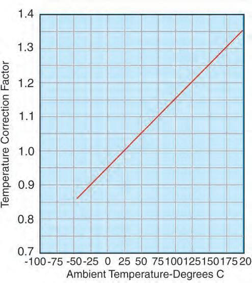
rected attenuation value from the tables.
For cables with low attenuation for their size,see the LMR, StripFlex, SFT, and CLL families of cables.
Attenuation Uniformity
The attenuation of any cable may not change uniformly as the frequency changes. Random and periodic impedance variations give rise to random and periodic attenuation responses. Narrow-band attenuation “spikes” such as that shown in Figure 3 can occur. If required, cables can be procured in various lengths where a maximum attenuation variation from nominal is specified over a customer defined frequency range.
Attenuation Stability
The attenuation of braided cables can increase with time and flexure. The change with time can be caused by corrosion of the braided shield, by contamination of the primary insulation due to jacket plasticizers, and by moisture penetration through the jacket. These effects can be essentially eliminated by encapsulating the braid with an appropriate flooding compound, as is done in the DB versions of the LMR cables.
(800)-TMS-COAX • www.timesmicrowave.com • (203)-949-8400 69
APPLICATION NOTES
A guide to the selection of RF coaxial cable
(continued)
Fig. 3
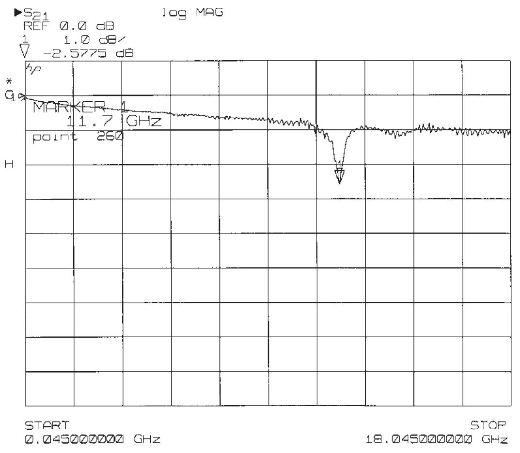
(Vapor penetration occurs at differing rates through all plastic and elastomeric materials.) Attenuation degradation is more pronounced at frequencies above 1 GHz. Cables
having bare copper and tinned copper braids exhibit far greater attenuation degradation than cables with silver plated braids. These effects are illustrated in Figure 5.
The following guidelines apply:
a. Tin plated braids: Below 1 GHz, cables manufactured with tin plated braids have 15-20% more attenuation than bare copper braids in the “as manufactured” condition, but are more stable than bare copper braided cables.
b. Foam polyethylene: Flexible braided cables with foam polyethylene dielectrics have approximately 15 to 40% lower attenuation than solid polyethylene cables of the same core size and impedance. However, some polyethylene foams can absorb moisture causing attenuation increases. LMR cables utilize a closed cell, non-hydroscopic foam composition and are not subject to this problem.
See LMR cables.
c. If PVC jackets are used, a Type IIA, non-contaminating PVC should be specified for applications where attenuation uniformity over time is important. Type I PVC’s contain plasticizers which can leach into the dielectric over time causing an increase in
attenuation.
d. The ultimate in attenuation stability can be achieved by specifying hermetically-sealed cable assemblies. These will preclude the ingress of con
taminants of any sort into the cable and result in the best stability, such as MilTech assemblies. Contact Times Microwave for more information on this type of assembly.
For flexible cables in extreme environmental conditions, a protected braid (e.g. LMR-DB) is recommended.
D. AVERAGE POWER RATING
Electrical losses in a coaxial cable result in the generation of heat in the center and outer conductors, as well as in the dielectric core. The power handling capability of a cable is related to the ability of the cable to dissipate this heat. The ultimate limiting factor in power handling is the maximum allowable operating temperature of the materials used in the cable, especially the dielectric. This is because most of the heat is generated at the center conductor of the cable. In general, the power handling capability of a given cable is inversely proportional to its at-
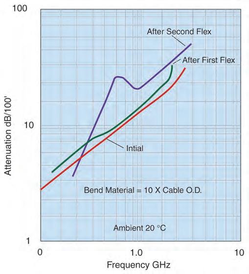
70
Attenuation vs. Frequency
Fig. 4
Attenuation vs. Flexure
Fig. 5
Attenuation Stability
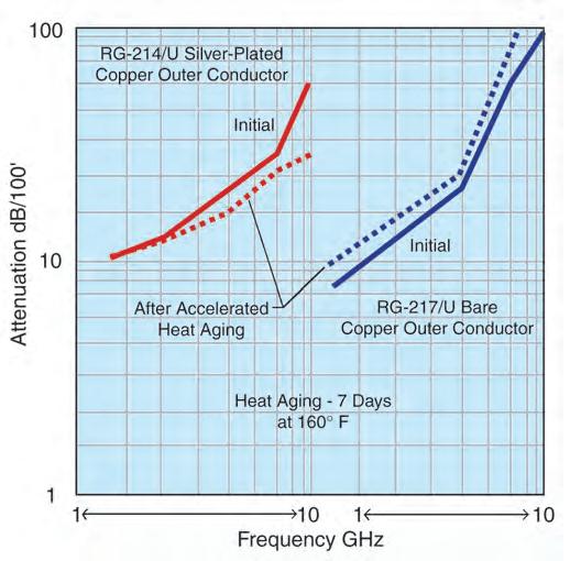
tenuation, and directly related to its size. The other factor is the heat transfer properties of the cable, especially the dielectric.
Cable power ratings must be derated by correction factors for the ambient temperature, altitude and VSWR encountered in a particular application. High ambient temperature and high altitude reduce the power rating of a cable by impeding heat transfer out of the cable. VSWR reduces power rating by causing localized hot spots in the cable.
To select the cable construction for a particular requirement, determine the average input power at the highest frequency from system requirements. Then determine the effective average input power as follows:
Effective Power = Average Power x (VSWR correction)
(Temp. correction) x (Alt. correction)
Temperature and altitude corrections are shown on Figures 6 and 7.
VSWR correction factor = 1 1
1/2 (VSWR + VSWR) + 1/2 k1 (VSWR - VSWR)
Where k, is shown in Figure 8. Select a cable
from the Attenuation and Power charts rated at this effective power level.
Note that the peak power handling capability of a cable is related to the maximum operating voltage rating. See Section E, below.
E. MAXIMUM OPERATING VOLTAGE
Care must be taken to ensure that the continuous voltage (and the peak voltage related to pulsed power conditions) applied to a cable is held below its maximum voltage rating. Note that there are two separate voltage ratings for a cable: Corona Voltage and Dielectric Withstanding Voltage:
1. Corona is a voltage related ionization phenomenon which causes noise generation, long term dielectric damage, and eventual breakdown of the cable. Thus, a cable cannot operate continuously with corona, and the maximum operating voltage must be less than the corona extinction level (extinction voltage) of the cable. The determination of corona voltages requires sensitive instrumentation capable of detecting the voltage induced ionization noise generation.
Fig. 6
Power Temperature Correction Factor
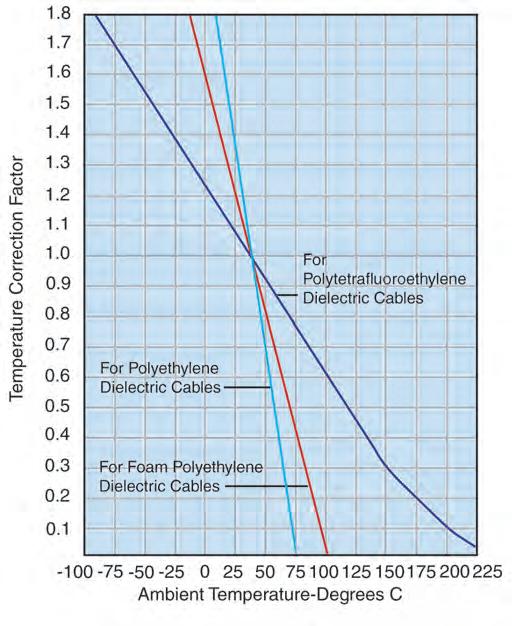
(800)-TMS-COAX • www.timesmicrowave.com • (203)-949-8400 71
APPLICATION NOTES
A guide to the selection of RF coaxial cable
Fig. 7
Power Altitude Correction Factor
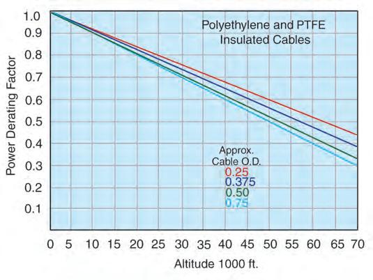
2. The Dielectric Withstanding Voltage, or dielectric strength of the cable, is a measure of the voltage level required to abruptly break down the dielectric employed in a cable. DWV testing requires less sensitive instrumentation, and is a test measurement where a voltage is applied to the cable for a limited time only, and monitored for current flow.
Maximum operating A.C. (RMS) voltage levels or peak voltage are given for each construction in the Cable Data Section of this catalog. The maximum permissible D.C. voltage level is conservatively 3 times the A.C. level.
To select a cable for a particular application, determine the actual RMS (peak /l.4) , RMS voltage = (peak voltage value) 1.4
or actual peak voltage = (RMS x value 1.4) from system requirements. Then determine the effective input voltage by multiplying the actual input voltage by the square root of the VSWR: Effective voltage = Actual voltage x (VSWR)1/2
Then select a cable with a maximum operating voltage greater than the effective RMS voltage. Maximum operating voltages are listed in the cable data section.
As the altitude where a cable is being used increases, the maximum operating voltage of a completed cable assembly is reduced due to the reduction in dielectric strength of the lower pressure air in the
(continued)
termination area.
F. SHIELDING AND CROSS-TALK (OR ISOLATION)
1. The shielding efficiency of a coaxial cable depends on the construction of its outer conductor. The most common constructions available are:
Single Braid: Consisting of bare, tinned, or silver plated round copper wires (70 to 95% coverage).
Double Braid: Consisting of two single braids as described above with no insulation between them.
Triaxial: Consisting of two single braids as described above with a layer of insulation between them.
Strip Braids: Consists of flat strips of copper rather than round wires (90% coverage).
Strip Outer Conductors/Spiral Flat Strips: Exhibiting @ 100% coverage.
Solid Sheath: Consisting of aluminum or copper tubing ( 100% coverage).
2. The relative shielding effectiveness of these constructions are illustrated in Figure 9 over the frequency range from 10 MHz to 8 GHz. This graph shows the level of signal which leaks through the outer shield of a one foot sample of each construction. The curves describing the performance of the flexible cables, i.e., the triax braid, double braid, and single braid construction are based on measured data.
8
Second VSWR Correction Factor Multiplier K
72
Fig.
G. CAPACITANCE
Capacitance in a cable is related to the dielectric material and the characteristic impedance. Typical capacitance values are shown in the General Electrical Properties on page 66 for some common coaxial lines.
As seen in the table, the higher impedance cables provide lower “capacitance per foot” values, resulting in reduced loading for data communications applications.
H. VELOCITY OF PROPAGATION
The velocity of propagation in a coaxial cable is determined primarily by the dielectric constant of the insulating material between the inner and outer conductors. This property is usually expressed as a percentage of the velocity of light in free space, and is typically noted as Vg or Vp.
The General Electrical Properties on page 66 shows the velocity of propagation and time delay of cables insulated with commonly used dielectrics.
Delay lines made from coaxial cable can sometimes benefit from using lower velocity cables, thus providing maximum delay in the shortest length. But, the difference in loss between the lower and higher velocity cables must also be taken into account.
I. ELECTRICAL LENGTH STABILITY
Applications such as antenna feed systems may require many cable assemblies that are trimmed to a specific electrical length. In these applications, the change of the electrical length of the cable with temperature, flexure, tension and other environmental factors is critical. The variation of electrical length with temperature for standard flexible cables is shown in Figure 10.
For polyethylene insulated cables:-100 to -250 parts per million/oC.
For TFE insulated cables:-50 to -100 parts/million/ oC.
The variation of electrical length with temperature for the standard foam dielectric semiflexible cables is -20 to -30 parts/million/oC.
Times has special flexible and semiflexible cable designs with improved electrical length versus temperature characteristics. Semiflexible cables
Fig. 9 Shielding Effectiveness
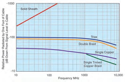
To estimate the total leakage in cables under 1100 ft. long, add 20 log L to the figure read from the graph (where L is the cable length in feet). The curve showing the typical performance of the semi-flexible (or solid sheath) cables is based on theory. In practice the shielding efficiency of interconnections made using semi-flexible (solid sheath) cables is limited by the leakage at the connectors.
3. The isolation (or cross talk) between two coax cable runs is the sum of the isolation factors of the two cables and the isolation due to the “coupling factor” between the runs. This coupling factor will depend on the relative spacing, positioning and environment of the cable runs and on the grounding practices employed. The coupling factor will substantially affect the isolation between the cable runs.
4. Measurements show that the RF(1 -30 MHz) cross talk between two single braided coaxes over a 20 foot run length is approximately 80 db down from the signal level inside the cables. The coaxes were laid side-by-side over the 20 foot test length. (This test data illustrates the affect of the “coupling factor” noted above.)
5. Special Constructions that provide enhanced shielding characteristics are available. These cables include the LMR, RD, and RDT families of cables, and the StripFlex, SFT, and TFlex cables.
(800)-TMS-COAX • www.timesmicrowave.com • (203)-949-8400 73
APPLICATION NOTES
A guide to the selection of RF coaxial cable
having an electrical length change with temperature as low as five parts/million per degree centigrade are available. See SFT and Coppersol Low Loss CLL cables.
J. CUT-OFF FREOUENCY
The cut-off frequency of a coaxial cable is that frequency at which modes of energy transmission other than the Tranverse Electro-Magnetic (TEM) mode can be generated. It does not mean that the TEM mode becomes highly attenuated. This frequency is a function of the mean diameter of
the conductors and the velocity of propagation of the cable. The higher modes are only generated at impedance discontinuities and in many situations
the cable can be operated above the cut-off frequency without substantial VSWR or insertion loss increase. However, it is recommended that cables not be operated above their cut-off frequency.
K. PULSE RESPONSE OF COAXIAL CABLES
1. The following characteristics must be considered when analyzing the Time Domain response of cable to pulses or step functions:
a: Impedance and Reflection;
b: Rise Time;
c: Amplitude;
d: Overshoot or Preshoot;
e: Pulse Echoes.
a: Impedance and Reflection
1. Select impedance to match system requirements.
2. The impedance will vary along the length of cable. Variations of +5% are not uncommon. Cables can
Phase Stability
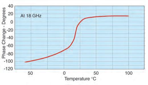
(continued)
Fig. 11 Pulse Distortion
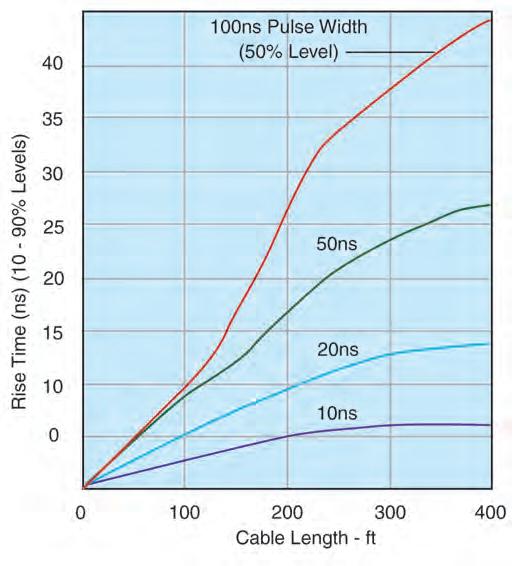
be produced to tolerances of 2%. Tighter tolerances are not recommended.
b: & c: Rise Time and Amplitude
1. The output rise time is a function of input rise time, pulse width and cable attenuation. A typical pulse response is shown in Figures 11 and 12, while a typical step response is shown in Figure 13. Increased cable temperature causes an increase in rise time and decrease in amplitude.
d: Overshoot or Preshoot
1. Figure 13 shows the overshoot which can be encountered with a 0.1 ns input pulse rise time in cables due to finite reflections. Such overshoot is not common in cables with longitudinally extruded
dielectrics.
2. Preshoot is encountered in some balanced delay lines and can be minimized by cable design.
e: Pulse Echoes
When a narrow pulse is placed on a cable, the distortions noted above will occur. In addition, a small pulse of energy may emerge after the initial pulse has arrived. This pulse echo is caused by finite periodic reflections within the cable. Normally the echo level can be neglected.
74
Fig. 10
L. SELF-GENERATED CABLE NOISE
A noted cable phenomenon, is the generation of accoustical and electrical noise when flexed. The acoustical noise is a function of mechanical motion within the cable. Such noise (and the associated mechanical and frictional force) is minimized by proper cable design. Electrical noise generation is attributed to an electrostatic effect, which in testing has exhibited more than 500 millivolts in RG cable. This noise voltage can be minimized by preventing motion between dielectrics and conductors or dissipating electrostatic charges between conductors and dielectrics with semiconducting layers. Low noise constructions must take into account the life expectancy and environmental conditions to which they are subjected. Times manufactures low noise cables for special applications.
M. OPERATING TEMPERATURE RANGE
1. The operating temperature range of flexible coaxial cable is determined primarily by the operating temperature range of the dielectric and jacketing materials. Note that only silver plated conductors are suitable for long term use at temperatures over
Pulse Amplitude vs. Length
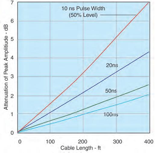
80 degrees C.
2. Operating temperature limits of the most commonly used dielectrics and jacket types are given in the following table:
MATERIAL Temperature
Range
Polytetrafluoroethylene
(PTFE) -75°C to + 250°C
Polyethylene -40°C to + 85°C
Foamed Polyethylene - 40°C to + 100°C
Foamed or Solid Ethylene
Propylene Jackets - 40°C to + l05°C
Fluorinated Ethylene
Propylene (FEP) -70°C to +200°C
Polyvinylchloride (PVC) - 50°C to + 85°C
Ethylene Chloro
Trifluoroethylene (ECTFE) - 65°C to + l50°C
Polyurethane -100°C to + 125°C
Perfluoroalkoxy (PFA) -65°C to + 260°C
Nylon -60°C to + 120°C
Ethylene Propylene - 40°C to + l05°C
High Molecular Weight
Polyethylene - 55°C to + 85°C
Crosslinked Polyolefin - 40°C to + 85°C
Silicone Rubber -70° to + 200°C
Silicone Impregnated
Fiberglass - 70°C to + 250°C
High Temperature Nylon
Fiber - 100°C to + 250°C
Fig. 13
Step Response (Output Amplitude vs. Time)
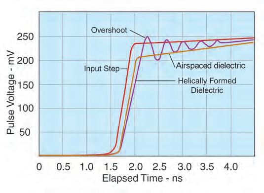
(800)-TMS-COAX • www.timesmicrowave.com • (203)-949-8400 75
Fig. 12
APPLICATION NOTES
A guide to the selection of RF coaxial cable (continued)
N. FLEXIBILITY
Coaxial cables with stranded center conductor and braided outer conductors are intended for use in those applications where the cable must flex repeatedly while in service. Cables with stranded center conductors will exhibit higher attenuation compared to cables with solid center conductors. In general, the higher the number of strands, the better the flexibility and the higher the attenuation. Standard braided outer conductor constructions will withstand over 1000 flexes through 180° if bent over a radius 20 times the diameter of the cable. Flexible cables may be stored, and are normally shipped, on reels with a hub radius greater than 10 times the diameter of the cable. If a flexible cable is to be installed in a fixed, bent configuration, the minimum bend radius recommended is 5 times the cable diameter. Tighter bends can be made. Special braid designs are available for improved flex-life.
Coaxial cables with a tubular aluminum or copper outer conductors, commonly referred to as semiflexible or semi-rigid cables, will not withstand more than ten 180° bends over a bend radius equal to 20 times the diameter of the cable. Semi-flex cables are normally shipped on reels having a hub radius of 20 times the O.D. of the cable. Semi-flex cables may be field bent for installation. The minimum recommended bend radius is equal to 10 times the O.D. of the cable. Cables bent on a bend radius of 5 times the O.D. of the cable may exhibit mechanical and electrical degradation.
O. ENVIRONMENTAL RESISTANCE
The life of a coaxial cable depends on many factors. The effects of ultra-violet exposure, high humidity, galvanic action, salt-water and corrosive vapors on the materials used are prime causes of cable failure. Resistance to flame must also be considered. The following guidelines apply:
a. Sunlight:For low temperature cables exposed to sunlight (ultra-violet), the use of high molecular weight polyethylene, with a specific carbon black particle size, % by weight and particle distribution, is recommended for maximum life expectancy. Polyvinylchloride jackets exhibit a life expectancy of less than 1/2 that of properly compounded polyethylene.
b. Humidity or water vapor can enter flexible cables through pin-holes in the jacket, at the con
nector, or by vapor transmission through the jacket. All materials exhibit a finite vapor transmission rate. For example, a ten foot length of cable with a polymer outer jacket exhibits a helium leak rate of approximately 10 -4 cc/sec/ft. Even the least porous thermoplastics, such as FEP, do not offer a significant improvement. In airborne applications, the combination of finite vapor transmission rates and large temperature extremes cause condensation in cables. The moisture can collect in low areas causing corrosion or shorting of a connector. One method of preventing moisture accumulation in cables is to fill all voids with a moisture-proofing compound which will not harden with age. See LMRDB and Imperveon Cables for additional data. Times also supplies hermetically sealed cable assemblies with leak rates of less than 10-5 cc/sec/ft.
c. Salt-water Immersion-The electrical characteristics of cable will be rapidly affected if the conductors are exposed to salt-water. Unless an immersion test is performed on the jacket, there is a good possibility of one pinhole per 1000 feet. Even if sufficient tests could be performed, damage during installation or damage from rodents normally will cause leakage. Pressure-tight, non-hosing cables capable of withstanding the pressure at the required cable depth can be recommended.
d. Corrosive Vapors: The use of tin and silver coatings does afford some protection against corrosive vapors. However, such protection is short-lived. For installation near salt-water or chemical plants, a filled cable such as LMR-DB or Imperveon is recommended.
e. Underground Burial & Galvanic Action: Underground moisture which comes in contact with any cable metals, will cause rapid corrosion. Tubular aluminum outer conductors have been almost destroyed in 90 days. Therefore, any cables installed underground should have pinhole-free jackets. Since jacket damage due to installation techniques and rodents can occur, cables filled with a flooding compound should be used. For maximum reliability against rodents, a steel tape armor with overjacketing is recommended.
f. Flame Resistance: Cables have different degrees of flame resistance depending on the jacket and dielectric material. “Flame retardant” cables are cables having limited flame spread (propagation).
76
PVC jackets offer some flame retardance, depending on the compound selected.
Flame retardant jackets, which are actually within the flame, will burn. If the flame is removed, they will self-extinguish. PVC jackets will not drip burning material. However, if the dielectric is polyethylene, the dielectric may drip ignited materials. PTFE and FEP will not support combustion, drip or burn. TMS has a series of Low Smoke / Low Toxicity cables to provide the utmost in protection. These cables utilize a proprietary TMS compound which is nonhalogenated and produces combustion products that are low smoke and low toxicity. See the LSSB/ LLSB, LMR-FR and M17 qualified cable lines.
P. CABLE STRENGTH
The break strength of the cable depends primarily on the strength of the outer conductor. The cables will normally achieve at least 70% of the break strength of the outer conductor, if the center conductor will stretch up to 10% before breakage. Caution must be taken with cables with coppercovered steel or alloy center conductors where breakage would occur with only 1 to 10% elongation. Conductor sizes less than 26 AWG can easily be broken during assembly operations. Special alloy conductors are available which can achieve a tensile strength of 110,000 psi and 10% elongation.
Q. QUALIFICATION APPROVAL
Often, cables must be qualified to certain standards to allow usage in particular applications. Typical examples of necessary qualifications are:
Military: Most military applications require that cable conform to particular specifications. Many of these specifications require the manufacturer to qualify product by conducting a series of tests on a length of cable with a military representative present as a witness. MIL-C-17, the basic specification for most coaxial cables, requires a Qualified Products List (QPL). TMS maintains numerous MIL-C-17 qualifications.
Commercial (UL) Approval: The building codes of many cities require that cables installed in their buildings be approved by the Underwriters Laboratories (UL). With UL service, the cable is subjected to a clearly defined series of tests and examinations, and has met the quality and safety standards
imposed by Underwriters Laboratories. Approval of new designs meeting UL standards normally can be made in a relatively short period of time. A large variety of TMS products are UL approved.
New York State Requirements: Article 15, Part 1120 of the New York State Uniform Fire Prevention and Building Code requires that materials used in some buildings and transit systems be tested and registered with The New York Department of State. For theTMS products tested, the fire/gas/toxicity data is found in: DOS file number 16120-9312034001.
London Underground Limited: TMS has gained LUL approval on a series of low-smoke cable constructions. These cables were tested for smoke emission, toxic fume emission, and flammability assessment against the requirements of the London Underground Code of Practice for fire safety.
Contact your TMS representative for more information regarding TMS product qualifications.
(800)-TMS-COAX • www.timesmicrowave.com • (203)-949-8400 77
Other catalogs available from Times Microwave
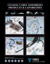

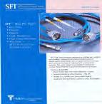
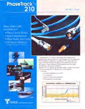
Coaxial Cable Assemblies, Products & Capabilities
High performance microwave cable assemblies for military electronic warfare systems, commercial aircraft, shipboard and ground based communications systems.
High Power RF Cables & Assemblies
Broad range of high power coax cables and assemblies for medical (MRI), semiconductor manufacturing equipment, lasers, particle physics experimentation and industrial applications.
Field Deployable Antenna Feeder Cables
LMR®, T-Com® and QEAMTM
cables are suited for the rigors of any mobile, portable or temporary field antenna deployment.


SFT® Coax Connectors & Assemblies
Professional grade test cables and adaptors for testing portable and mobile radios.

PhaseTrack® 210 Test Cables & Connectors
Thermally stable test cables with removable, interchangeable connectors that experience the lowest phase change with temperature fluctuations.

Tactical Field Deployable Antenna Cables
T-Com®, QEAMTM, and LLSBTM cables suitable for the harshest mobile, portable or temporary military field deployed antenna applications.
Broadband Wireless Cable Assemblies
Purchasing and technical information for 50 ohm coaxial cables assemblies and jumperslicensed and unlicensed bands.
SiO2 Silicon Dioxide
Coaxial Cable Assemblies
Crack-free, low loss glass dielectric and laser welded technology combine to provide unequaled low VSWR and hermetic sealing performance.
Shipboard Low Smoke
Coaxial Cables
Low-loss, low smoke coaxial cables for military and commercial shipboard applications.
Blind Mate Antenna Applications
Unique interconnect systems for quick avionics and electronic warfare system antenna connect/ disconnect.
78
Order at www.timesmicrowave.com


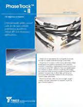
LMR® Flexible Communications Coax Times LMR coax cables- the industry standard for the utmost in low loss flexible 50 ohm coax cable for every type of wireless communications system.
Silverline®
Test Cables
Durable, cost effective, high performance cable assemblies designed for use in a broad range of test and interconnect applications.
Silverline® TuffGrip®
Test Cables
For wireless system testing, make connections with just one wrench!
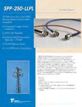
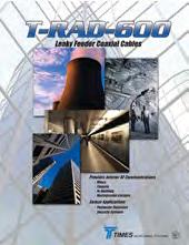

SilverLine VNA™
Precision test cables with excellent loss, VSWR and phase/flexure stability.
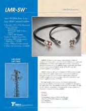
PhaseTrack®-II
PhaseTrack®- II is based on the unique, thermally stable Times Microwave Systems proprietary TF5™ Dielectric material making it the most stable dielectric material available.

SPP-250-LLPL SPP-250LLPL50 Ohm low loss plenum rated coaxial cable assemblies employ a flexible corrugated copper tube outer conductor over a tape wrapped low density PTFE dielectric core which results in an exceptional combination of low loss, light weight and flexibility.
T-RAD®-600
T-RAD 50 Ohm, leaky feeder coax radiating cable provide cost effective radio frequency coverage in enclosed or underground areas, where single point source antennas are not practical.
SilverLine®-LP™
SilverLine-LP is flexible test cable specifically designed for low passive intermodulation performance and to withstand the physical abuse of field work.
LMR®-SW™
LMR-SW 50 Ohm low loss coaxial cables employ a thin wall, seamless aluminum outer conductor which results in an exceptional combination of low loss, light weight and flexibilty.
Times-Protect®
An innovative line of grounding and lightning protection for wireless networks. These unique surge protection devices address applications throughout the entire useful RF frequency range from DC with capability up to and including 6 GHz.
(800)-TMS-COAX • www.timesmicrowave.com • (203)-949-8400 79

An Amphenol Company Catalog TL-16 (11/17) Printed in U.S.A. © Times Microwave Systems 2017 TIMES MICROWAVE SYSTEMS An Amphenol Company USA 358 Hall Ave., Wallingford, CT 06492-5039 USA Phone: 203-949-8400 Fax: 203-949-8423 800-TMS-COAX • www.timesmicrowave.com
