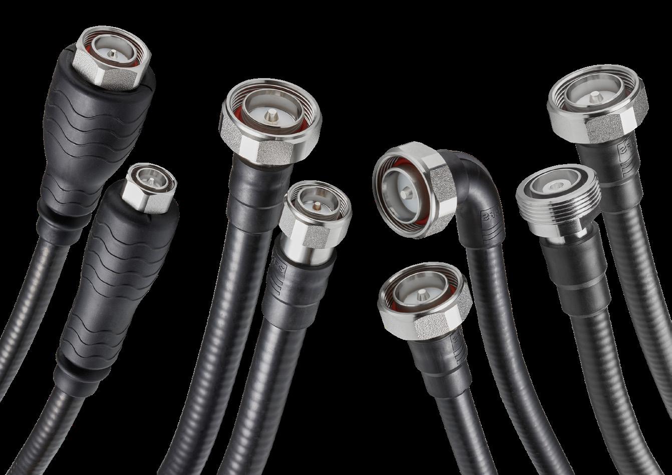
OMNI FIT™ CONNECTORS FOR EVERY APPLICATION AND BUDGET
OMNI FIT connectors are known throughout the industry for their precisionengineered performance, ease of installation and long life in the field. They can be used with copper and aluminum cables, and are the perfect complement to our CELLFLEX® and CELLFLEX Lite communications cables in any scenario:
• Tower and rooftop deployments
• Small cell deployments in dense urban environments
• Indoor and underground deployments
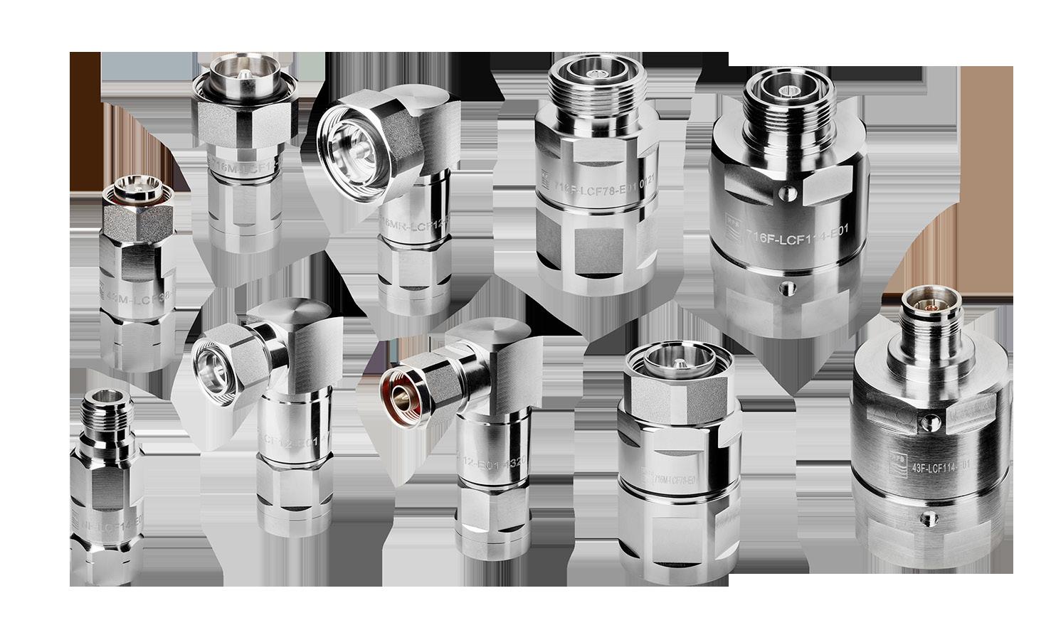
A COMPLETE PORTFOLIO TO CHOOSE FROM
Simply choose the OMNI FIT connectors that match your requirements:
OMNI FIT Premium E01 series connectors are fully optimized to deliver the ultimate combination of electrical performance, simplicity, durability and cost.
OMNI FIT Standard C03 series connectors deliver a first-class feature set at a very cost-effective price point.
Our complete portfolio of OMNI FIT Premium and OMNI FIT Standard connectors is available with spacing-saving 4.3-10 interfaces as well as traditional Type-N and 7-16 DIN interfaces in all interface combinations, versions and variants.
DESIGNED FOR FUTUREPROOF EVOLUTION TO 5G
OMNI FIT connectors support all frequencies up to 6 GHz, making them the perfect choice for smooth evolution to 5G globally.
You can take advantage of newly available spectrum such as Citizens Broadband Radio Service (CBRS), C-Band and License Assisted Access (LAA) today, then seamlessly switch to different frequencies tomorrow.
IDEAL FOR RETROFITS AND UPGRADES
Because OMNI FIT connectors are backwards compatible with so many installed cables, they’re a very cost-effective way to instantly gain access to the fully frequency range supported by existing cables.
Simply replace legacy, frequency-limited connectors with OMNI FIT connectors to extend the life of current installations, reduce upgrade costs and gain higher returns on previous investments.
OMNI FIT™ CONNECTORS FOR EVERY APPLICATION AND BUDGET
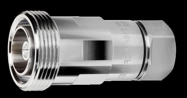
OMNI FIT PREMIUM: MAXIMUM VALUE FOR THE PRICE
OMNI FIT Premium connectors are tested and proven to deliver outstanding PIM and VSWR performance at all frequencies up to 6 GHz. They feature an ultra-compact, lightweight and extremely robust two-piece design that simplifies installations and avoids the need for additional parts that can complicate installations or be lost.
To ensure watertight durability, OMNI FIT Premium E01 series connectors include a built-in seal against the outer conductor and against the cable jacket so there’s no need for external sealing. They can be installed using the same tools and following the same principles as the previous generation D01 connectors.
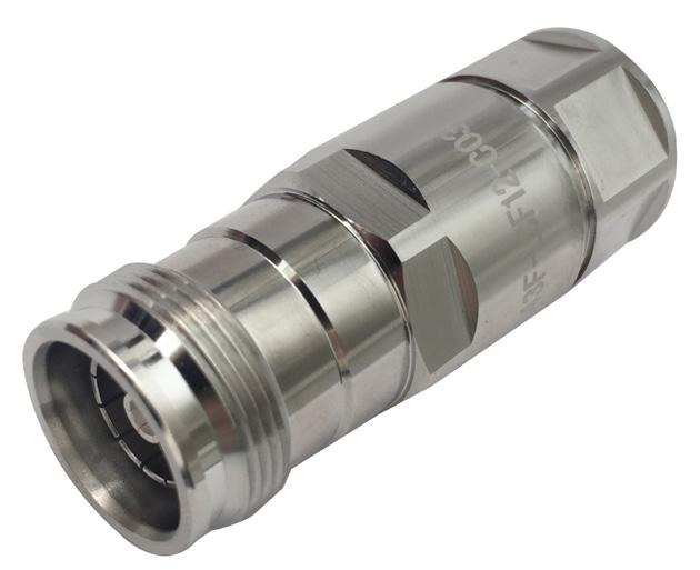
OMNI FIT STANDARD: COST-EFFECTIVE CONNECTORS WITH NO COMPROMISES
OMNI FIT Standard connectors provide key performance and design features that help you squeeze every last bit of performance out of infrastructure at a very appealing price point.
The high-performance C03 series connectors provide excellent PIM and VSWR ratings that help to maintain signal quality and system performance end-to-end. They also feature a lightweight design that simplifies installation and minimizes weight burdens.
With three attachment options to choose from — push-pull, hand-screw and hex-head — OMNI FIT Standard connectors are easy to install in any environment.
Accelerate Installations
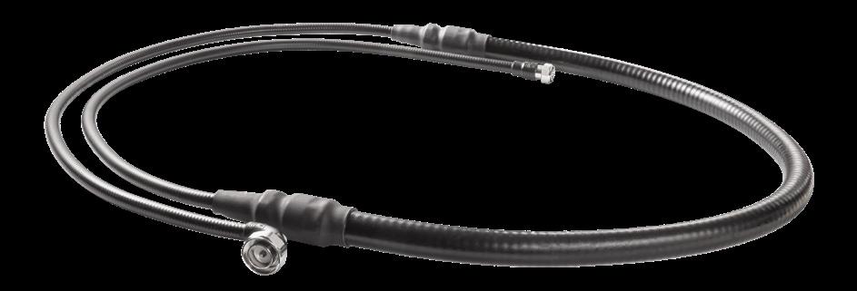
CELLFLEX MultiFlex cabling solutions feature 1-meter (3-ft) CELLFLEX jumpers connected to each end of a CELLFLEX feeder cable of any length with OMNI FIT™ connectors. You choose the jumper, cable and connector combination you need, and we take care of assembly.
With a pre-assembled CELLFLEX MultiFlex solution, you’ll save time and effort across indoor and
outdoor installations. And you’ll have the ultimate combination: The flexibility of jumpers, the outstanding performance of larger feeder cables and the reliability of factory-installed connectors.
All CELLFLEX MultiFlex solutions support frequencies up to 6 GHz to get you to 5G faster anywhere in the world.
® MULTIFLEX
CELLFLEX
ALL-IN-ONE SOLUTION
NEWPRODUCT 4 5 Transmission Line Solutions Transmission Line Solutions
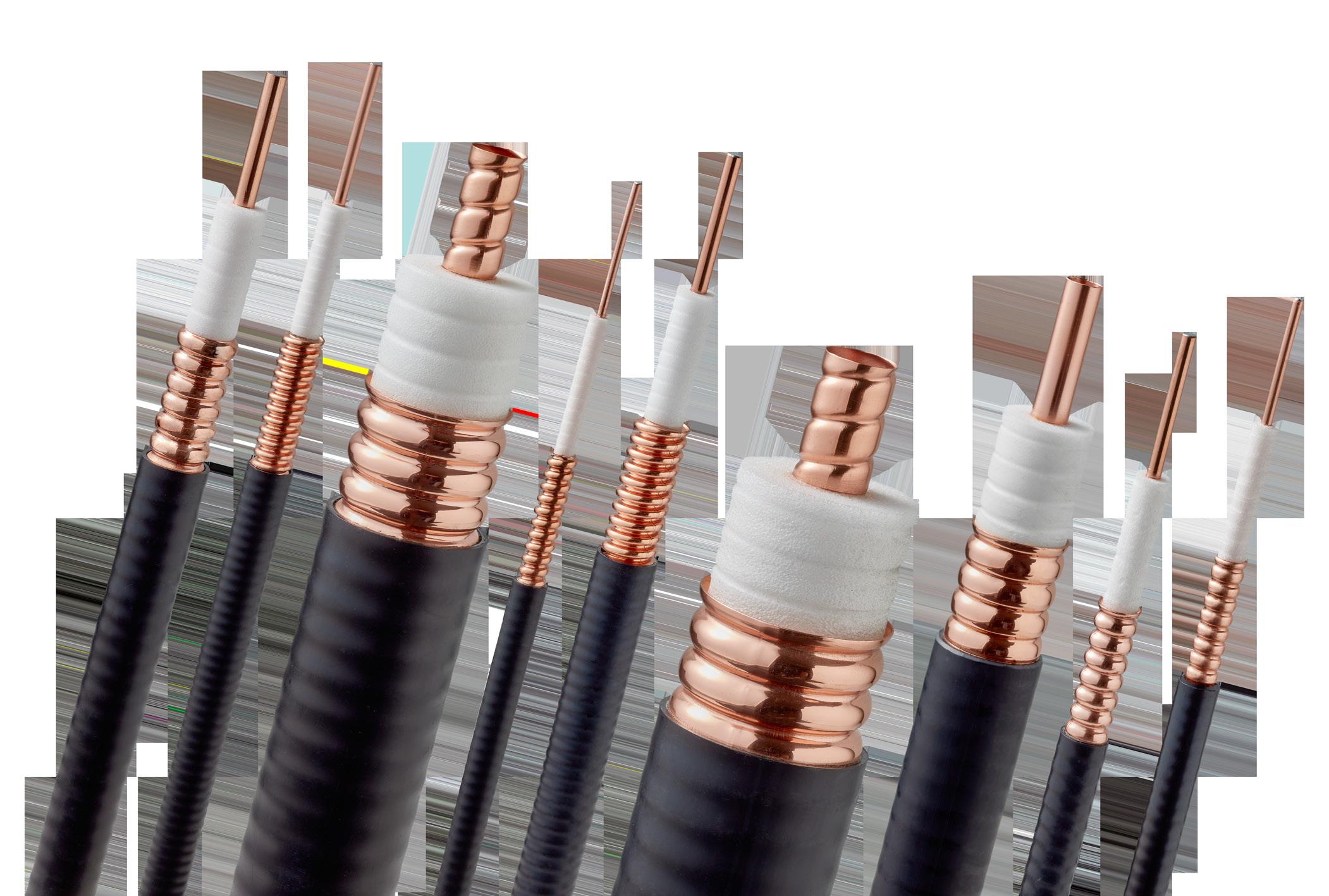
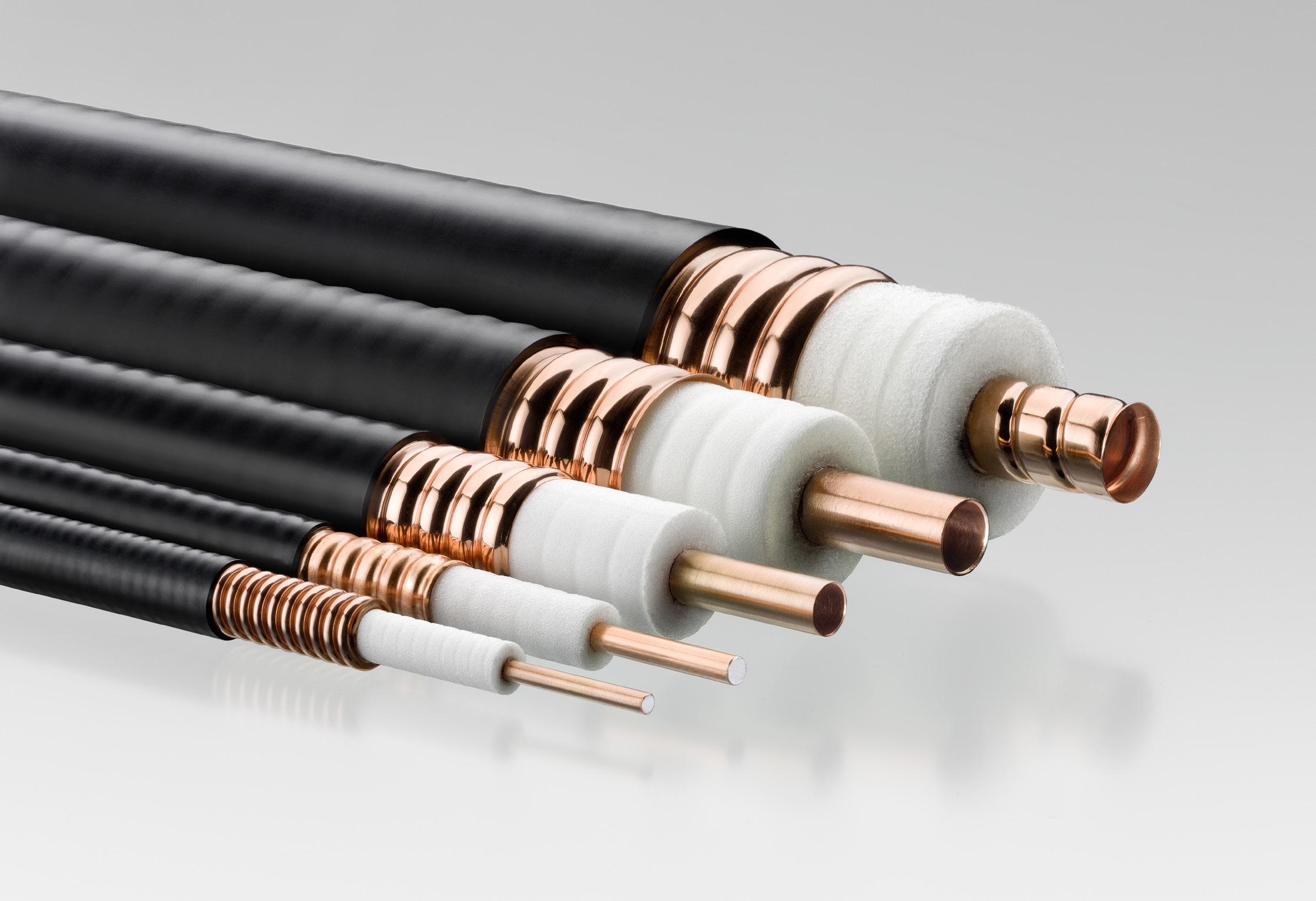
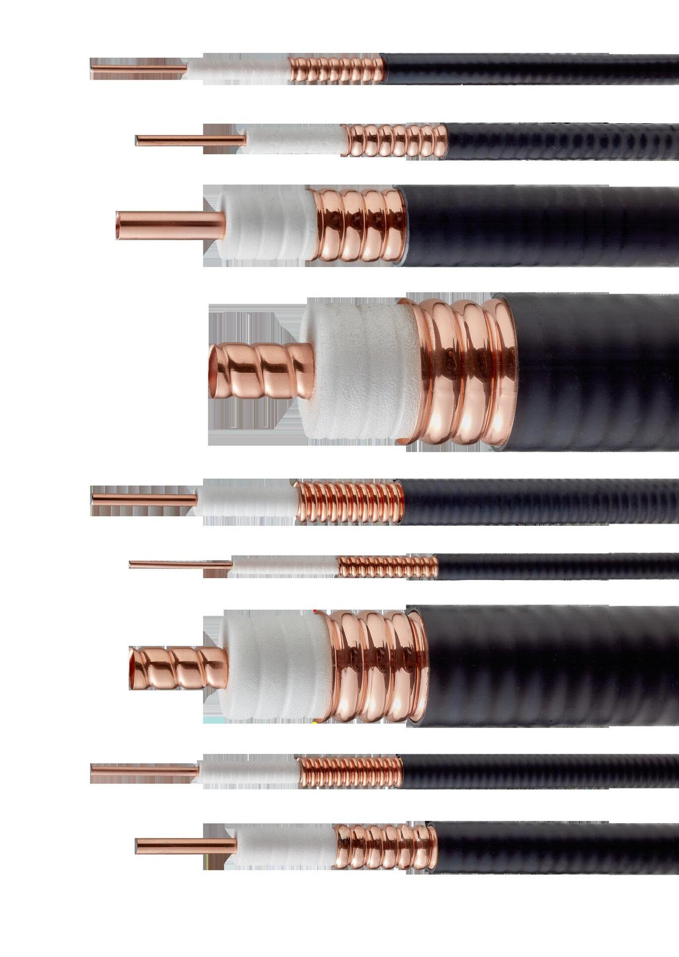
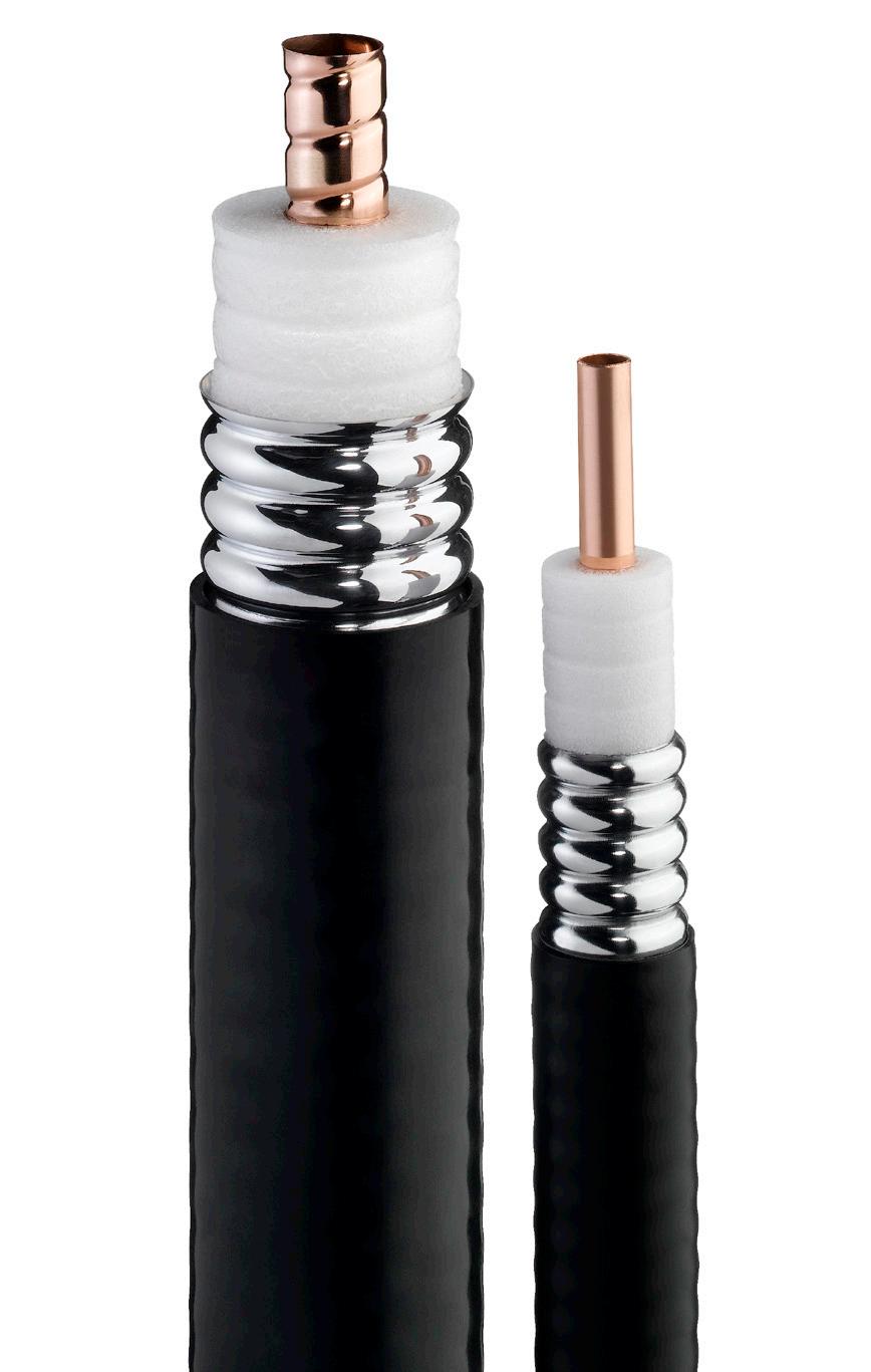
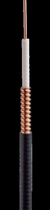
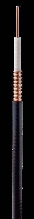
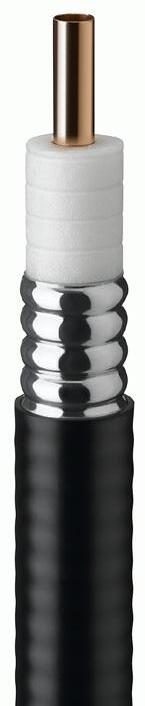
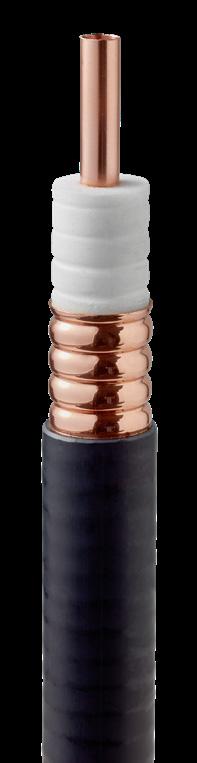
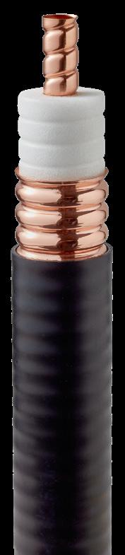
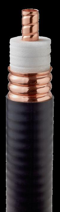
CELLFLEX LOW-LOSS FOAM-DIELECTRIC COAXIAL CABLE
ORDERING INFORMATION
SCF14 Series: 20.4 GHz
flame retardant:
PRODUCT SPECIFICATIONS
GENERAL SPECIFICATIONS
Dimensions Over Jacket mm (in) 7.8 (0.307)
Min. Bending Radius, Repeated mm (in) 25 (0.984)
Jacket Type Polyethylene, PE Bending Moment Nm (lb-ft) 0.7 (0.5)
Tensile Strength N (lb) 600 (135)
Recommended/Maximum Clamp
m (ft) 0.2 / 0.2 (0.67 / 0.67)
SCF14-50J
SCF14-50JFN
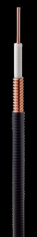
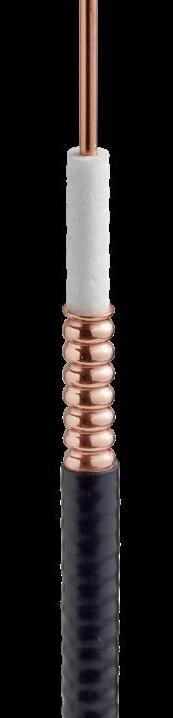
CELLFLEX LOW-LOSS FOAM-DIELECTRIC COAXIAL CABLE
ORDERING INFORMATION
SCF38 Series: 13.4 GHz
Jacketing Options Standard Attenuation Cable Model Numbers
Outdoor standard: SCF38-50J
Indoor flame retardant: SCF38-50JFN
PRODUCT SPECIFICATIONS
GENERAL SPECIFICATIONS
Dimensions Over Jacket mm (in) 10.2 (0.402)
Min. Bending Radius, Repeated mm (in) 25 (0.984)
Jacket Type Polyethylene, PE
Bending Moment Nm (lb-ft) 1.4 (1)
Tensile Strength N (lb) 600 (135)
Recommended/Maximum Clamp
Spacing m (ft) 0.25 / 0.25 (0.8 / 0.8)
TEMPERATURE SPECIFICATIONS
(°F) -40 to 60 (-40 to 140) Installation - JFNA
Operation
RELATED PRODUCTS
(°F) -25 to 60 (-13 to 140)
(°F) -70 to 85 (-94 to 185)
(°F) -50 to 85 (-58 to 185)
4.3-10 Male Right Angle
4.3-10 Male
for Series E01 TRIM-SET-S14-D01 Universal Trimming Tool TRIM-IS14-D01 Univ. Trimming Tool Insert
(°F) -40 to 60 (-40 to 140)
Installation - JFNA °C (°F) -25 to 60 (-13 to 140)
(°F) -70 to 85 (-94 to 185)
(°F) -50 to 85 (-58 to 185)
RELATED PRODUCTS
Premium Connector Series E01
Model Number Type
NM-SCF38-E01 N Type Male
NF-SCF38-E01 N Type Female
43M-SCF38-E01 4.3-10 Male
Tools for Series E01
TRIM-SET-S38-D01 Universal Trimming Tool
TRIM-IS38-D01 Univ. Trimming Tool Insert
Accessories
Model Number Type
RSB-S38/L14 Stainless Steel Clamp
TRIM-T01 Hand Tool Kit
Jacketing Options Standard Attenuation Cable Model Numbers Outdoor
standard:
Indoor
ELECTRICAL
Operating Frequency Band GHz 20.4 Max. VSWR / Return Loss dB (VSWR) Standard 20 (1.222) Premium 23 (1.152) Premium 24 (1.135) ATTENUATION Frequency, MHz dB per 100 m dB per 100 ft Power, kW 800 17.30 5.27 0.38 1800 26.90 8.20 0.25 2400 31.30 9.60 0.21 3500 39.10 11.90 0.17 5000 48.00 14.60 0.14 6000 53.40 16.30 0.12 8000 63.40 19.30 0.10 10000 72.60 22.10 0.09 12000 81.00 24.80 0.08 16000 97.00 29.60 0.07 18000 105.00 31.90 0.06 20400 113.00 34.60 0.06
Spacing
SPECIFICATIONS
Premium Connector Series E01 Model Number Type 716M-SCF14-E01 7-16 Male NM-SCF14-E01 N Type Male NF-SCF14-E01 N Type Female 43MR-SCF14-E01
43M-SCF14-E01
Tools
Accessories Model
TRIM-T01
Kit
°C
°C
°C
Number Type
Hand Tool
TEMPERATURE SPECIFICATIONS Installation
Storage
°C
ELECTRICAL SPECIFICATIONS Operating Frequency Band GHz 13.4 Max. VSWR / Return Loss dB (VSWR) Standard 20 (1.222) Premium 23 (1.152) Premium 24 (1.135) ATTENUATION Frequency, MHz dB per 100 m dB per 100 ft Power, kW 800 12.73 3.88 0.62 1800 20.05 6.11 0.39 2400 23.70 7.21 0.33 3500 29.50 9.01 0.27 5000 36.60 11.16 0.22 6000 41.00 12.48 0.19 8000 49.00 14.94 0.16 10000 56.50 17.21 0.14 12000 63.50 19.37 0.12 13400 68.30 20.82 0.12
°C
Installation
°C
Operation °C
6 7 Transmission Line Solutions Transmission Line Solutions
Storage
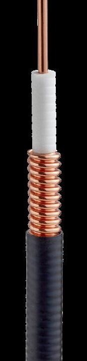
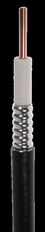
CELLFLEX LOW-LOSS FOAM-DIELECTRIC COAXIAL CABLE
ORDERING INFORMATION
Outdoor standard:
Indoor flame retardant:
PRODUCT SPECIFICATIONS
GENERAL SPECIFICATIONS
SCF12 Series: 10.6 GHz
SCF12-50J
SCF12-50JFN
Dimensions Over Jacket mm (in) 13.7 (0.539)
Min. Bending Radius, Repeated mm (in) 32 (1.3)
Jacket Type Polyethylene, PE
Bending Moment Nm (lb-ft) 2.5 (1.84)
Tensile Strength N (lb) 650 (146)
Recommended/Maximum Clamp Spacing m (ft) 0.3 / 0.5 (1 / 1.64)
RELATED PRODUCTS
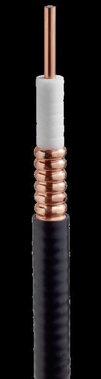
CELLFLEX LOW-LOSS FOAM-DIELECTRIC COAXIAL CABLE
ORDERING INFORMATION
LCF14 Series: 15.8 GHz
Outdoor standard: LCF14-50J
Indoor flame retardant: LCF14-50JFN
PRODUCT SPECIFICATIONS
GENERAL SPECIFICATIONS
Dimensions Over Jacket mm (in) 10 (0.394)
Min. Bending Radius, Single mm (in) 40 (1.575)
Min. Bending Radius, Repeated mm (in) 85 (3.346)
Jacket Type Polyethylene, PE
Bending Moment Nm (lb-ft) 1.9 (1.4)
Tensile Strength N (lb) 890 (200)
Recommended/Maximum Clamp
Spacing m (ft) 0.5 / 1 (1.75 / 3.25)
RELATED PRODUCTS
7-16 Male Right Angle
4.3-10 Male Right Angle
for Series C03
TRIM-SET-S12-C02 Universal Trimming Tool Premium Connector Series E01
7-16 Male
716F-SCF12-E01 7-16 Female 43M-SCF12-E01 4.3-10 Male 43F-SCF12-E01 4.3-10 Female
NM-SCF12-E01 N Type Male
NF-SCF12-E01 N Type Female
716MR-SCF12-E01 7-16 Male Right Angle
43MR-SCF12-E01 4.3-10 Male Right Angle
NMR-SCF12-E01 N Type Male Right Angle
Tools for Series E01
TRIM-SET-S12-D01 Universal Trimming Tool
TRIM-IS12-D01 Univ. Trimming Tool Insert Accessories
Number Type
Stainless Steel Clamp
RSB-S12/78 Stainless Steel Clamp TRIM-T01 Hand Tool Kit
Premium Connector Series E01/D01
Model Number Type
43M-LCF14-E01 4.3-10 Male
NM-LCF14-E01 N Type Male
NF-LCF14-E01 N Type Female
NMR-LCF14-E01 N Type Male Right Angle
Tools for Series D01
TRIM-SET-L14-D01 Universal Trimming Tool
TRIM-IL14-D01 Univ. Trimming Tool Insert
Accessories Model Number Type
RSB-S38/L14 Stainless Steel Clamp
GKSPEED20-14C Grounding Kit, CCA Wire
GKSPEED20-14P Grounding Kit, Premium
TRIM-T01 Hand Tool Kit
Standard Attenuation Cable Model Numbers
Jacketing Options
ELECTRICAL SPECIFICATIONS Operating Frequency Band GHz 15.8 Max. VSWR / Return Loss dB (VSWR) Standard 20 (1.222) Premium 23 (1.152) Premium 24 (1.135) ATTENUATION Frequency, MHz dB per 100 m dB per 100 ft Power, kW 800 12.40 3.77 0.59 1800 19.10 5.82 0.38 2400 22.30 6.81 0.33 3500 27.50 8.39 0.27 5000 33.70 10.30 0.22 6000 37.40 11.40 0.20 8000 44.10 13.50 0.17 10000 50.30 15.30 0.15 12000 56.10 17.10 0.13 15800 66.20 20.20 0.11
TEMPERATURE SPECIFICATIONS Installation °C (°F) -40 to 60 (-40 to 140) Installation - JFNA °C (°F) -25 to 60 (-13 to 140) Storage °C (°F) -70 to 85 (-94 to 185) Operation °C (°F) -50 to 85 (-58 to 185) Jacketing Options Standard Attenuation Cable Model Numbers
ELECTRICAL SPECIFICATIONS Operating Frequency Band GHz 10.6 Max. VSWR / Return Loss dB (VSWR) Standard 20 (1.222) Premium 23 (1.152) Premium 24 (1.135) ATTENUATION Frequency, MHz dB per 100 m dB per 100 ft Power, kW 800 9.57 2.92 0.74 1800 14.90 4.55 0.47 2400 17.50 5.35 0.40 3500 21.80 6.63 0.32 5000 26.80 8.16 0.26 6000 29.80 9.09 0.24 8000 35.50 10.80 0.20 10000 40.60 12.40 0.17
Standard Connectors Model Number Type 716M-SCF12-C03 7-16 Male 716F-SCF12-C03 7-16 Female 43M-SCF12-C03 4.3-10 Male 43MH-SCF12-C03 4.3-10 Male, Hand Screw 43MP-SCF12-C03 4.3-10 Male, Push-Pull 43F-SCF12-C03 4.3-10 Female NM-SCF12-C03 N Type Male NF-SCF12-C03 N Type Female 716MR-SCF12-C03
43MR-SCF12-C03
Tools
Model
716M-SCF12-E01
Number Type
Model
RSB-S12
SPECIFICATIONS Installation °C (°F) -40 to 60 (-40 to 140) Installation - JFNA °C (°F) -25 to 60 (-13 to 140) Storage °C (°F) -70 to 85 (-94 to 185) Operation °C (°F) -50 to 85 (-58 to 185) 8 9 Transmission Line Solutions Transmission Line Solutions
TEMPERATURE
CELLFLEX LOW-LOSS FOAM-DIELECTRIC COAXIAL CABLE
ORDERING INFORMATION
LCF38 Series: 13.5 GHz
PRODUCT SPECIFICATIONS
GENERAL SPECIFICATIONS
Dimensions Over Jacket mm (in) 11.2 (0.441)
Min. Bending Radius, Single mm (in) 50 (2)
Min. Bending Radius, Repeated mm (in) 95 (4)
Jacket Type Polyethylene, PE
Bending Moment Nm (lb-ft) 1.9 (1.4)
Tensile Strength N (lb) 530 (119)
Recommended/Maximum Clamp Spacing m (ft) 0.5 / 1 (1.75 / 3.25)
Connectors
Number Type NM-LCF38-070 N Type Male NF-LCF38-070 N Type Female
NMR-LCF38-071 N Type Male Right Angle Tools for Series C03
TRIM-38-L03 Combination Prep Tool
Connector Series E01
Number Type 43M-LCF38-E01 4.3-10 Male
NM-LCF38-E01 N Type Male
NF-LCF38-E01 N Type Female
NMR-LCF38-E01 N Type Male Right Angle Tools for Series E01
TRIM-SET-L38-E01 Universal Trimming Tool
TRIM-IL38-E01 Univ. Trimming Tool Insert
RSB Clamp Lining
Hand Tool Kit
CELLFLEX LOW-LOSS FOAM-DIELECTRIC COAXIAL CABLE
ORDERING INFORMATION
LCF12 Series: 8.8 GHz
PRODUCT SPECIFICATIONS
GENERAL SPECIFICATIONS
Dimensions Over Jacket mm (in) 15.9 (0.62)
Min. Bending Radius, Single mm (in) 70 (3)
Min. Bending Radius, Repeated mm (in) 125 (5)
Jacket Type Polyethylene, PE
Bending Moment Nm (lb-ft) 6.5 (4.8)
Tensile
(ft) 0.6 / 1 (2 / 3.25)
TEMPERATURE SPECIFICATIONS
to
(-40 to 140)
to 185)
RELATED PRODUCTS
Standard Connector Series C03
Model Number Type
716M-LCF12-C03 7/16 Male
716F-LCF12-C03 7/16 Female
43M-LCF12-C03 4.3-10 Male
43MH-LCF12-C03 4.3-10 Male, Hand Screw
43MP-LCF12-C03 4.3-10 Male, Push-Pull
43F-LCF12-C03 4.3-10 Female
NM-LCF12-C03 N Type Male
NF-LCF12-C03 N Type Female
716MR-LCF12-C03 7/16 Male Right Angle
43MR-LCF12-C03 4.3-10 Male Right Angle
NMR-LCF12-C02 N Type Male Right Angle
Tools for Series C03
TRIM-SET-L12-C02 Universal Trimming Tool
TRIM-IL12-C02 Trimming Tool Insert
Premium Connector Series E01
7/16 Male
7/16 Female
4.3-10 Male
4.3-10 Female NM-LCF12-E01 N Type Male
for Series E01
N Type Male Right Angle
TRIM-SET-L12-D01 Universal Trimming Tool
TRIM-IL12-D01 Univ. Trimming Tool Insert
TRIM-LCF12-D01-A Automatic Trimming Tool
TRIM-B13 Blades for Automatic Tool
Accessories
Model Number Type
HOIST1-12L Hoisting Grip
GKSPEED20-12C Grounding Kit, CCA Wire
GKSPEED20-12P
BOOT-CP-12 Cushion Plug
RSB-12 Stainless Steel Clamp
TRIM-T01 Hand Tool Kit Multi-Block Hangers MBH12-2-F 2 per layer, 1 layer, 2 runs
2 per layer, 3 layers, 6 runs
1 per layer, 1 layer, 1 run
1 per layer, 2 layers, 2 runs
1 per layer, 3 layers, 3 runs
Jacketing Options Premium Attenuation Cable Model Numbers Lite Low-Loss Cable Model Numbers Outdoor standard: LCF12-50J LCF12-50JL Indoor
LCF12-50JFNL
flame retardant: LCF12-50JFN
Spacing
ELECTRICAL SPECIFICATIONS Operating Frequency Band GHz 8.8 Max. VSWR / Return Loss dB (VSWR) Standard 20 (1.222) Premium 23 (1.152) Premium 24 (1.135) ATTENUATION Frequency, MHz dB per 100 m dB per 100 ft Power, kW Version JA JL JA JL JA JL 800 6.48 6.94 1.98 2.12 1.16 1.28 1800 10.10 10.70 3.07 3.26 0.75 0.83 2200 11.30 11.90 3.44 3.63 0.67 0.75 2600 12.40 13.10 3.78 3.98 0.61 0.68 3500 14.70 15.40 4.47 4.69 0.51 0.58 5000 18.00 18.80 5.50 5.72 0.42 0.47 6000 20.70 20.80 6.30 6.34 0.37 0.43 8000 23.80 24.50 7.26 7.47 0.32 0.36 8800 25.20 25.90 7.69 7.90 0.30 0.34
Strength N (lb) Copper 1050 (236) Aluminum 800 (180) Recommended/Maximum Clamp
m
Model
716M-LCF12-E01
NF-LCF12-E01 N
Female 716MR-LCF12-E01
43MR-LCF12-E01
NMR-LCF12-E01
Tools
Number Type
716F-LCF12-E01
43M-LCF12-E01
43F-LCF12-E01
Type
7/16 Male Right Angle
4.3-10 Male Right Angle
Installation °C (°F) -40
Installation
°C
Storage °C (°F) -70
85
Operation °C
60
- JFNA
(°F) -25 to 60 (-13 to 140)
to
(-94 to 185)
(°F) -50 to 85 (-58
GKSPEED20-12S
GKSPEED60-12S
JSTRIP-12-3
CEAR-12
BOOT4-12-4
Grounding Kit, Premium
Grounding Kit, Standard
Grounding Kit, High Speed
Jacket Stripping Tool
Connector Grounding Kit
Feed Through Assembly
MBH12-6-F
MBHS12-2-F
MBHS12-3-F
Jacketing Options Standard Attenuation Cable Model Numbers Outdoor standard: LCF38-50J Indoor flame retardant: LCF38-50JFN
MBHS12-1-F
ELECTRICAL SPECIFICATIONS Operating Frequency Band GHz 13.5 Max. VSWR / Return Loss dB (VSWR) Standard 20 (1.222) Premium 23 (1.152) Premium 24 (1.135) ATTENUATION Frequency, MHz dB per 100 m dB per 100 ft Power, kW 800 10.10 3.07 0.72 1800 15.50 4.74 0.47 2400 18.20 5.54 0.40 3500 22.40 6.82 0.32 5000 27.40 8.34 0.27 6000 30.30 9.25 0.24 8000 35.80 10.90 0.20 10000 40.80 12.40 0.18 12000 45.50 13.90 0.16 13500 48.80 14.90 0.15 RELATED
Standard
Model
PRODUCTS
Premium
Model
Accessories Model Number
RSB-38/12
RSB-12
TRIM-T01
TEMPERATURE SPECIFICATIONS Installation °C (°F) -40 to 60 (-40 to 140) Installation - JFNA °C (°F) -25 to 60 (-13 to 140) Storage °C (°F) -70 to 85 (-94 to 185) Operation °C (°F) -50 to 85 (-58 to 185) 10 11 Transmission Line Solutions Transmission Line Solutions
Type
RSB Clip (in Combination)
CELLFLEX LOW-LOSS FOAM-DIELECTRIC COAXIAL CABLE
ORDERING INFORMATION
LCF78 Series: 5 GHz
PRODUCT SPECIFICATIONS
Tensile
Recommended/Maximum
RELATED PRODUCTS
TRIM-SET-L78-D01 Universal Trimming Tool
TRIM-IL78-D01 Univ. Trimming Tool Insert
TRIM-LCF78-D01-A Automatic Trimming Tool
TRIM-FL78 Flaring Tool
Accessories Model Number Type
HOIST1-78L Hoisting Grip
GKSPEED20-78C Grounding Kit, CCA Wire
GKSPEED20-78P Grounding Kit, Premium
GKSPEED20-78S Grounding Kit, Standard
GKSPEED60-78S Grounding Kit, High Speed
JSTRIP-78-2 Jacket Stripping Tool
CEAR-78 Connector Grounding Kit
BOOT4-78-4 Feed Through Assembly
BOOT-CP-78 Cushion Plug
RSB-78 Stainless Steel Clamp
TRIM-T01 Hand Tool Kit
Multi-Block Hangers
MBH78-2-F 2 per layer, 1 layer, 2 runs
MBH78-6-F 2 per layer, 3 layers, 6 runs
MBHS78-1-F 1 per layer, 1 layer, 1 run
MBHS78-2-F 1 per layer, 2 layers, 2 runs
per layer, 3 layers, 3 runs
CELLFLEX LOW-LOSS FOAM-DIELECTRIC COAXIAL CABLE
ORDERING INFORMATION
LCFS114 Series: 3.7 GHz
PRODUCT SPECIFICATIONS
TEMPERATURE
RELATED PRODUCTS
Standard Connector Series C02 Model Number Type
716M-LCF114-C02 7/16 Male
716F-LCF114-C02 7/16 Female
NM-LCF114-C02 N Type Male
NF-LCF114-C02 N Type Female
Tools for Series C02
TRIM-SET-L114-C02 Universal Trimming Tool
TRIM-IL114-C02 Trimming Tool Insert
Premium Connector Series E01
Model Number Type
716M-LCF114-E01 7/16 Male
716F-LCF114-E01 7/16 Female
43M-LCF114-E01 4.3-10 Male
43F-LCF114-E01 4.3-10 Female
NM-LCF114-E01 N Type Male
NF-LCF114-E01 N Type Female Tools for Series E01
TRIM-SET-L114-D01 Universal Trimming Tool
TRIM-IL114-D01 Univ. Trimming Tool Insert
Accessories
Model Number Type
HOIST1-114L Hoisting Grip
GKSPEED20-114C Grounding Kit, CCA Wire
GKSPEED20-114P Grounding Kit, Premium
GKSPEED60-114S Grounding Kit, High Speed
JSTRIP-114-2 Jacket Stripping Tool
CEAR-114 Connector Grounding Kit
RSB-114 Stainless Steel Clamp
TRIM-T01 Hand Tool Kit Multi-Block Hangers
MBHS114-1-F 1 per layer, 1 layer, 1 run
MBHS114-2-F 1 per layer, 2 layers, 2 runs
MBHS114-3-F 1 per layer, 3 layers, 3 runs
Jacketing Options Premium Attenuation Cable Model Numbers Lite Low-Loss Cable Model Numbers Outdoor standard: LCF78-50JA LCF78-50JL Indoor flame retardant: LCF78-50JFNA LCF78-50JFNL
GENERAL SPECIFICATIONS
Over Jacket mm (in) 27.8
Min. Bending Radius, Single mm (in) 120 (5) Min. Bending Radius, Repeated mm (in) 250 (10)
Type Polyethylene, PE Bending Moment Nm (lb-ft) 13
Dimensions
(1.094)
Jacket
(10)
Strength N (lb) 1440
(324)
Clamp Spacing m (ft) 0.8 / 1
ELECTRICAL SPECIFICATIONS Operating Frequency Band GHz 5 Max. VSWR / Return Loss dB (VSWR) Standard 20 (1.222) Premium 23 (1.152) Premium 24 (1.135) ATTENUATION Frequency, MHz dB per 100 m dB per 100 ft Power, kW Version JA JL JA JL JA JL 800 3.48 3.72 1.06 1.13 2.41 2.85 1800 5.44 5.76 1.66 1.76 1.54 1.84 2200 6.09 6.43 1.86 1.96 1.38 1,65 2600 6.70 7.05 2.04 2.15 1.25 1.50 3600 8.30 8.47 2.53 2.58 1.03 1.25 4000 8.60 8.98 2.62 2.74 0.97 1.18 5000 9.81 10.20 2.99 3.11 0.85 1.04
(2.75 / 3.25)
Standard Connector Series C03 Model Number Type 716M-LCF78-C03 7/16 Male 716F-LCF78-C03 7/16 Female 43M-LCF78-C03 4.3-10 Male 43MH-LCF78-C03 4.3-10 Male, Hand Screw 43MP-LCF78-C03 4.3-10 Male, Push-Pull 43F-LCF78-C03 4.3-10 Female NM-LCF78-C03 N Type Male NF-LCF78-C03 N Type Female Tools for Series C03 TRIM-SET-L78-C02 Universal Trimming Tool TRIM-IL78-C02 Trimming Tool Insert TRIM-FL78 Flaring Tool Premium Connector Series E01 Model Number Type 716M-LCF78-E01 7/16 Male 716F-LCF78-E01 7/16 Female 43M-LCF78-E01 4.3-10 Male 43F-LCF78-E01 4.3-10 Female NM-LCF78-E01 N Type Male NF-LCF78-E01
Female Tools
N Type
for Series E01
MBHS78-3-F
Jacketing Options Premium Attenuation Cable Model Numbers Outdoor standard: LCFS114-50JA Indoor flame retardant: LCFS114-50JFNA Indoor CPR certified LCFS114-50CPR
1
Jacket mm (in) 39
Min. Bending Radius, Single mm (in) 200 (8) Min. Bending Radius, Repeated mm (in) 380 (15) Jacket Type Polyethylene, PE Bending Moment Nm (lb-ft) Copper 43 (32) Aluminum 22 (16.2) Tensile Strength N (lb) Copper 2490 (560) Aluminum 1850 (416) Recommended/Maximum Clamp Spacing m (ft) 1 / 1.2 (3.25 / 4) ELECTRICAL SPECIFICATIONS Operating Frequency Band GHz 3.7 Max. VSWR / Return Loss dB (VSWR) Standard 20 (1.222) Premium 23 (1.152) Premium 24 (1.135) ATTENUATION Frequency, MHz dB per 100 m dB per 100 ft Power, kW 800 2.47 0.75 4.45 1900 4.00 1.22 2.75 2200 4.35 1.33 2.53 2600 4.80 1.46 2.29 2700 4.90 1.49 2.24 3000 5.21 1.59 2.11 3300 5.51 1.68 2.00 3600 5.80 1.77 1.90 3700 5.90 1.80 1.86
GENERAL SPECIFICATIONS Dimensions Over
(1.54)
SPECIFICATIONS Installation °C (°F) -40 to 60 (-40 to 140) Installation - JFNA °C (°F) -25 to 60 (-13 to 140) Storage °C (°F) -70 to 85 (-94 to 185) Operation °C (°F) -50 to 85 (-58 to 185)
TEMPERATURE
SPECIFICATIONS Installation °C (°F) -40 to 60 (-40 to 140) Installation - JFNA °C (°F) -25 to 60 (-13 to 140) Storage °C (°F) -70 to 85 (-94 to 185) Operation °C (°F) -50 to 85 (-58 to 185)
12 13 Transmission Line Solutions Transmission Line Solutions
CELLFLEX LOW-LOSS FOAM-DIELECTRIC COAXIAL CABLE
ORDERING INFORMATION PRODUCT SPECIFICATIONS
LCF158 Series: 2.75 GHz
CELLFLEX LOW-LOSS FOAM-DIELECTRIC COAXIAL CABLE
LCF158 J Series: 2.75 GHz
RELATED PRODUCTS
Universal Trimming Tool
TRIM-IL158-D01 Univ. Trimming Tool Insert
RELATED PRODUCTS
Standard Connector Series C02 Model Number Type
716M-LCF158-C02
GKSPEED20-158C Grounding Kit, CCA Wire
GKSPEED20-158P Grounding Kit, Premium
GKSPEED60-158S Grounding Kit, High Speed JSTRIP-158-2 Jacket Stripping Tool
Connector Grounding Kit
BOOT4-158-1 Feed Through Assembly RSB-158 Stainless Steel Clamp
TRIM-T01 Hand Tool Kit
Hangers
TRIM-SET-L158-C02 Universal Trimming Tool
TRIM-IL158-C02 Trimming Tool Insert
Premium Connector Series E01 Model Number Type
716M-LCF158-E01 7/16 Male
716F-LCF158-E01 7/16 Female
43M-LCF158-E01 4.3-10 Male
4.3-10 Female
N Type Male
N Type Female Tools for Series E01
TRIM-SET-L158-D01 Universal Trimming Tool
TRIM-IL158-D01 Univ. Trimming Tool Insert
Number Type HOIST1-158L Hoisting Grip
Grounding Kit, CCA Wire
Grounding Kit, Premium GKSPEED60-158S Grounding Kit, High Speed JSTRIP-158-2 Jacket Stripping Tool
Connector Grounding Kit BOOT4-158-1 Feed Through Assembly
Stainless Steel Clamp TRIM-T01 Hand Tool Kit Multi-Block Hangers
2 per layer, 1 layer, 2 runs
1 per layer, 1 layer, 1 run
1 per layer, 2 layers, 2 runs
Jacketing Options Premium Attenuation Cable Model Numbers Outdoor standard: LCF158-50JA Indoor flame retardant:
Indoor flame retardant: LCF158-50CPR
LCF158-50JFNA
GENERAL
Over Jacket mm (in) 50.2 (1.98)
Bending Radius, Single mm (in) 200 (8)
Bending Radius, Repeated mm (in) 500 (20) Jacket Type Polyethylene, PE Bending Moment Nm (lb-ft) 42 (31) Tensile Strength N (lb) 2500 (562) Recommended/Maximum Clamp Spacing m (ft) 1.2 / 1.5 (4 / 5) TEMPERATURE SPECIFICATIONS Installation °C (°F) -40 to 60 (-40 to 140) Installation - JFNA °C (°F) -25 to 60 (-13 to 140) Storage °C (°F) -70 to 85 (-94 to 185) Operation °C (°F) -50 to 85 (-58 to 185) ELECTRICAL SPECIFICATIONS Operating Frequency Band GHz 2.75 Max. VSWR / Return Loss dB (VSWR) Standard 20 (1.222) Premium 23 (1.152) Premium 24 (1.135) ATTENUATION Frequency, MHz dB per 100 m dB per 100 ft Power, kW 800 1.98 0.60 5.66 1700 3.06 0.93 3.66 2000 3.36 1.03 3.34 2200 3.56 1.08 3.15 2400 3.75 1.14 2.99 2600 3.93 1.20 2.85 2700 4.02 1.23 2.79 2750 4.07 1.24 2.75 Standard Connector Series C02 Model Number Type 716M-LCF158-C02 7/16 Male 716F-LCF158-C02 7/16 Female NM-LCF158-C02 N Type Male NF-LCF158-C02 N Type Female Tools for Series C02 TRIM-SET-L158-C02 Universal Trimming Tool TRIM-IL158-C02 Trimming Tool Insert Premium Connector Series E01 Model Number Type 716M-LCF158-E01 7/16 Male 716F-LCF158-E01 7/16 Female 43M-LCF158-E01 4.3-10 Male 43F-LCF158-E01 4.3-10 Female NM-LCF158-E01 N Type Male NF-LCF158-E01 N Type Female Tools for Series E01 TRIM-SET-L158-D01
SPECIFICATIONS Dimensions
Min.
Min.
Accessories Model Number
Type HOIST1-158L Hoisting Grip
CEAR-158
Multi-Block
MBH158-2-F 2
MBH158-6-F 2 per layer, 3 layers, 6 runs MBHS158-1-F 1 per layer, 1 layer, 1 run MBHS158-2-F 1
per layer, 1 layer, 2 runs
per layer, 2 layers, 2 runs
Jacketing Options Lite Low-Loss Cable Model Numbers Outdoor standard: LCF158-50JL Indoor flame retardant: LCF158-50JFNL
GENERAL SPECIFICATIONS Dimensions Over Jacket mm (in) 50.2 (1.98) Min. Bending Radius, Single mm (in) 200 (8) Min. Bending Radius, Repeated mm (in) 500 (20) Jacket Type Polyethylene, PE Bending Moment Nm (lb-ft) 40.7 (30.7) Tensile Strength N (lb) 1800 (405) Recommended/Maximum Clamp Spacing m (ft) 1.2 / 1.5
5) TEMPERATURE SPECIFICATIONS Installation °C (°F) -40 to 60 (-40 to 140) Installation - JFNL °C (°F) -25 to 60 (-13 to 140) Storage °C (°F) -70 to 85 (-94 to 185) Operation °C (°F) -50 to 85 (-58 to 185) ELECTRICAL SPECIFICATIONS Operating Frequency Band GHz 2.75 Max. VSWR / Return Loss dB (VSWR) Standard 20 (1.222) Premium 23 (1.152) Premium 24 (1.135) ATTENUATION Frequency, MHz dB per 100 m dB per 100 ft Power, kW 800 2.17 0.66 5.39 1700 3.33 1.02 3.51 2000 3.67 1.12 3.19 2200 3.88 1.18 3.02 2400 4.08 1.24 2.87 2600 4.28 1.31 2.73 2700 4.38 1.34 2.67 2750 4.43 1.35 2.64
ORDERING INFORMATION PRODUCT SPECIFICATIONS
(4 /
7/16 Male 716F-LCF158-C02 7/16 Female NM-LCF158-C02 N Type Male NF-LCF158-C02 N Type Female Tools for Series C02
43F-LCF158-E01
NM-LCF158-E01
NF-LCF158-E01
Model
MBH158-2-F
MBH158-6-F
MBHS158-1-F
MBHS158-2-F
Accessories
GKSPEED20-158C
GKSPEED20-158P
CEAR-158
RSB-158
2 per layer, 3 layers, 6 runs
14 15 Transmission Line Solutions Transmission Line Solutions
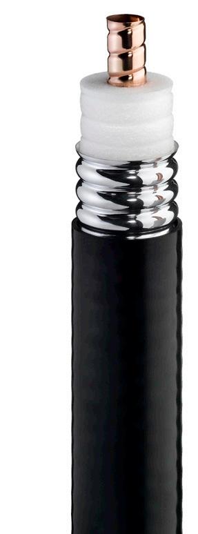
CLEARFILL ® LINE PLENUM-RATED CABLES
RFS ClearFill®Line plenum-rated wideband cables deliver outstanding electrical and mechanical performance, and operate in frequencies from 380 MHz to 6 GHz to support all in-building wireless technologies and applications. These air dielectric coaxial cables are thoroughly tested for safe use within the “environmental air handling space” in ceilings as well as in more traditional plenum applications. They’re available in copper or lighter weight aluminum models to meet any installation requirements.
IMPROVE IN-BUILDING WIRELESS NETWORK PERFORMANCE
ClearFill®Line plenum-rated cables provide low attenuation and excellent return loss.
FREQUENCY
They also feature robust construction that reduces the risk of performance issues:
• A continuous, star-shaped dielectric provides complete support for the inner conductor to eliminate electrical and mechanical problems in tight bending areas.
• The solid outer conductor creates a continuous RFI/EMI shield that minimizes system interference.
LEVERAGE NEW SPECTRUM
With wideband spectrum support up to 6 GHz, ClearFillLine plenum-rated cables make it easy to take advantage of newly available Citizens Broadband Radio Service (CBRS) spectrum in the 3.5 GHz band and LTE License Assisted Access (LAA) spectrum in the unlicensed 5 GHz band.
ORDERING INFORMATION
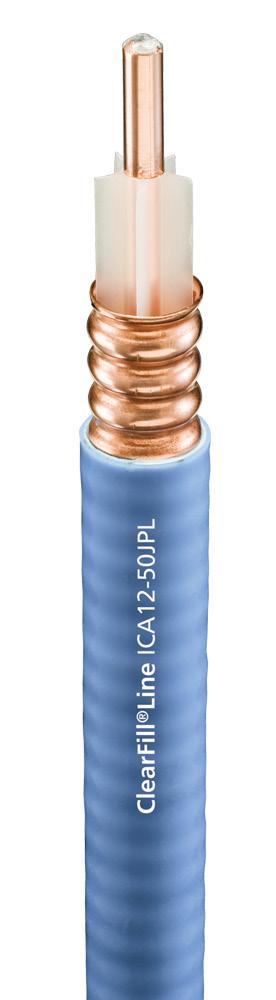
CLEARFILL ® LINE PLENUM-RATED CABLES
ICA12 Series: 6 GHz
PRODUCT SPECIFICATIONS
549 (150)
Clamp Spacing m (ft) 0.5 / 0.9 (1.8 / 3)
TEMPERATURE SPECIFICATIONS
-40 to 85 (-40 to 185)
(°F) -40 to 85 (-40 to 185)
RELATED PRODUCTS
Wideband operation
Support technologies and applications in bands ranging from 380MHz up to 6GHz
(MHz) RETURN LOSS (dB) VSWR 698-960 24 1.13 1395-1432 24 1.13 1700-2155 24 1.13 2300-2700 20 1.22 3550-4200 18 1.29 5150-6000 18 1.29
RANGE
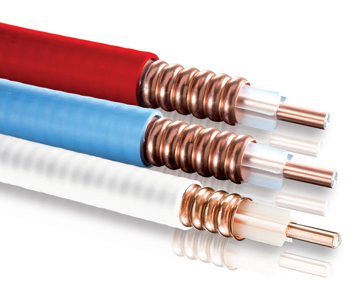
1/2” Plenum-Rated Cables Jacket Color Wideband Copper Cables Model Numbers Wideband Aluminum Cables Model Numbers Blue ICA12-50JPL ICA12-50JPLL Red ICA12-50JPLR ICA12-50JPLLR Black ICA12-50JPLB ICA12-50JPLLB White ICA12-50JPLW ICA12-50JPLLW
SPECIFICATIONS Dimensions Over Jacket mm (in) 15.93 (0.627) Min. Bending Radius, Single mm (in) 76 (3) Min. Bending Radius, Repeated mm (in) 127 (5) Jacket Type PVC,
ASTM
Bending
Nm
Copper
Aluminum
Copper
Aluminum
GENERAL
Plenum Rated, UV rated to
G155, Water-resistant
Moment
(lb-ft)
4.1 (3)
5.4 (4) Tensile Strength N (lb)
1112 (250)
Recommended/Maximum
Installation °C (°F) -20 to
Storage °C (°F)
Operation °C
ELECTRICAL SPECIFICATIONS Operating Frequency Band GHz 6 Max. VSWR / Return Loss dB (VSWR) 24 (1.13) @ 698-960 MHz 24 (1.13) @ 1395-1432 MHz 24 (1.13) @ 1700-2155 MHz 20 (1.22) @ 2300-2700 MHz 18 (1.29) @ 3550-4200 MHz 18 (1.29) @ 5150-6000 MHz ATTENUATION Frequency, MHz dB per 100 m dB per 100 ft Power, kW Version JPL JPLL JPL JPLL JPL JPLL 800 6.64 7.28 2.02 2.22 1.09 1.06 1800 10.50 11.5 3.2 3.49 0.69 0.67 2200 11.80 12.80 3.59 3.92 0.62 0.61 2600 13.00 14.2 3.96 4.31 0.56 0.55 3600 15.80 17.10 4.81 5.22 0.47 0.46 4000 16.80 18.30 5.13 5.56 0.44 0.43 5000 19.30 20.90 5.88 6.36 0.38 0.38 6000 21.6 23.3 6.58 7.11 0.34 0.34 Standard Connector
Model Number Type 716M-LCF12-C03 7/16 Male 716F-LCF12-C03 7/16 Female 43M-LCF12-C03 4.3-10 Male 43F-LCF12-C03 4.3-10 Female NM-LCF12-C02-6 N Type Male NF-LCF12-C02-6 N Type Female NM-LCF12-C03 N Type Male NF-LCF12-C03 N Type Female Tools for Series C03/C02 TRIM-ICA12-C02 Universal Trimming Tool Premium Connector Series E01 Model Number Type 716M-LCF12-E01 7/16 Male 716F-LCF12-E01 7/16 Female 43M-LCF12-E01 4.3-10 Male 43F-LCF12-E01 4.3-10 Female NM-LCF12-E01 N Type Male NF-LCF12-E01 N Type Female Tools for Series E01
60 (-4 to 140)
Series C03/C02
TRIM-SET-L12-D01 Universal Trimming Tool
Accessories Model Number Type HOIST1-12L
GKSPEED20-12C
Kit, CCA
GKSPEED20-12P
Kit,
GKSPEED20-12S
Kit,
GKSPEED60-12S
JSTRIP-12-3
CEAR-12
BOOT4-12-4
BOOT-CP-12
RSB-12
TRIM-T01
Multi-Block
MBH12-2-F 2 per layer, 1 layer, 2 runs MBH12-6-F 2 per layer, 3 layers, 6 runs MBHS12-1-F 1 per layer, 1 layer, 1 run MBHS12-2-F 1 per layer, 2 layers, 2 runs MBHS12-3-F 1 per layer, 3 layers, 3 runs 17 Transmission Line Solutions 16 Transmission Line Solutions
Hoisting Grip
Grounding
Wire
Grounding
Premium
Grounding
Standard
Grounding Kit, High Speed
Jacket Stripping Tool
Connector Grounding Kit
Feed Through Assembly
Cushion Plug
Stainless Steel Clamp
Hand Tool Kit
Hangers
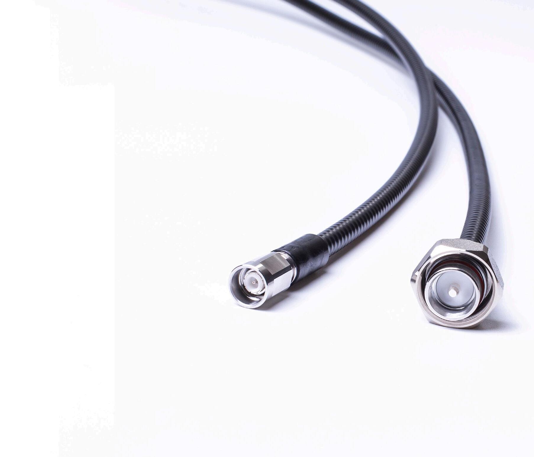
GET HIGH-PERFORMANCE JUMPER CABLES FOR ANY APPLICATION, ANY SIZE
RFS is a global leader in RF jumper cables and offers a completes portfolio of jumper cables that meet any requirements.
CELLFLEX Factory-Fit Jumpers are ideal for indoor environments and other locations where jumper connectors do not require weatherproofing.
CELLFLEX SecureFit Booted Jumpers are ideal for outdoor environments and other locations where jumper connectors need to be protected from the elements.
All of our CELLFLEX jumper cables support frequencies up to 6 GHz to simplify your network evolution and protect your investment.
CHOOSE FROM SUPER-FLEXIBLE AND LOW-LOSS JUMPER CABLES
CELLFLEX Factory-Fit Jumpers and CELLFLEX SecureFit Booted Jumpers are designed for seamless connection to our renowned CELLFLEX foam dielectric coaxial cables:
CELLFLEX super-flexible jumper cables combine outstanding bending characteristics and electrical performance to improve quality and efficiency in the most challenging deployment scenarios.
CELLFLEX low-loss jumper cables deliver extremely low attenuation that increases the efficiency of signal transfers in any RF system.
MIX AND MATCH JUMPER CABLE CONFIGURATIONS AND FEATURES TO MEET APPLICATION AND SITE REQUIREMENTS
We offer a variety of features and configuration options for each jumper cable type and size. Options include:
• Jacket type: Standard or flame-retardant
• Connector type for each endpoint: NEX10, 4.3-10, N-Type or 7-16 DIN right-angled or straight connectors
• Performance: UltraPIM or Premium PIM
• Length: 1 m to 20 m or 3 ft to 50 ft
We manufacture and stock the most popular combinations and can deliver custom lengths when required.
SIMPLIFY 4G, 5G AND SMALL CELL DEPLOYMENTS IN CROWDED URBAN ENVIRONMENTS
As you upgrade and add network technologies to already-crowded sites, the ability to make more coaxial cable connections in smaller spaces is crucial.
CELLFLEX super-flexible 1/4-inch jumpers with miniaturized NEX10 and 4.3-10 connectors make urban installations faster and easier. They’re ideal for installations in highly constrained spaces, such as street poles, and for short-distance connections. To ensure optimal attenuation over longer distances, rely on our low-loss 1/2-inch jumper cables.
GET HIGH-PERFORMANCE JUMPER CABLES FOR ANY APPLICATION, ANY SIZE
MAINTAIN ULTRA-HIGH PERFORMANCE END-TO-END
You can’t afford to compromise on performance. Jumper cables that provide the ultimate in electrical performance are essential to guarantee end-to-end transmission line performance and support the next generations of applications.
CELLFLEX jumper cables feature our industry-leading UltraPIM performance, and we guarantee the performance specifications for every jumper cable.
All of our jumpers are fully tested for PIM, VSWR (return loss) and interface performance. Test results are available online for products sold globally.
GET MORE VALUE FROM EXISTING EQUIPMENT
We understand your need to extract maximum value from the investments you’ve already made in network equipment.
While some jumper cable vendors are discontinuing older connector types, such as N-Type and 7-16 DIN, we continue to offer the interfaces.
BRING US YOUR TOUGHEST DEPLOYMENT CHALLENGES
We have the expertise and experience needed to adapt our jumper designs and deliver innovative, custom jumper cables that are designed to meet your unique requirements and resolve the most difficult installation challenges.
One of our recent innovations includes jumper cables with shortened, molded boots that fit within the available space on a specific outdoor small cell radio while still allowing a plastic cover to close over the end of the jumper.
SUPPORT DEPLOYMENTS ANYWHERE IN THE WORLD

We understand your need to extract maximum value from the investments you’ve already made in network equipment While some jumper cable vendors are discontinuing older connector types, such as N-Type and 7-16 DIN, we continue to offer the interfaces.
CLUSTER CONNECTORS
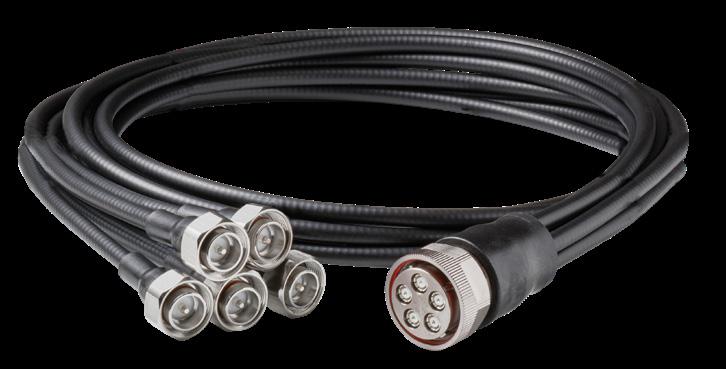
Make More Jumper Connections in Less Space
Our innovative new jumper cables with RF cluster connectors are ideal for connecting to highly integrated antennas that have a large number of RF ports in a very compact footprint.
Each cluster connector supports connections to multiple RF ports to enable
connections to more than 20 multiband 4T4R and 8T8R ports within the space of a typical antenna end cap.
Simplify your next deployment using cluster jumpers with MQ4/MQ5 connectors or M-LOC systems.
SCF Jumpers Low-Loss LCF Jumpers SCF38 SCF14 SCF12 LCF38 LCF12
RFS CELLFLEX Jumpers
Super-flexible
LEARN MORE
18 19 Transmission Line Solutions Transmission Line Solutions
PROTECT CRITICAL CONNECTIONS WITH THE ULTIMATE WEATHERPROOFING BOOT
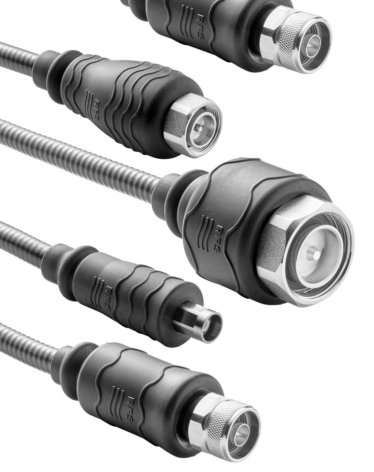
RFS CELLFLEX SecureFit Booted Jumpers feature specially designed, injection-molded weatherproof boots that protect jumper connections from all forms of moisture — from rain to snow and ice — as well as salt, sand, dust and other contaminants that can corrode connectors, degrade connection quality and reduce connector lifespan.
CELLFLEX SecureFit Booted Jumpers are available in a wide variety of RFS jumper cables sizes, for all RFS-supported connector types and in all RFS jumper configurations. In 2022, RFS has added smaller cable sizes and more models with right-angle and NEX10 connectors to the product portfolio.
With the addition of the new jumper models, RFS’ SecureFit Booted Jumper portfolio now includes the following jumper sizes and factoryinstalled connectors:
• 1/4-inch and 3/8-inch jumpers with 4.3-10 or NEX10 connectors
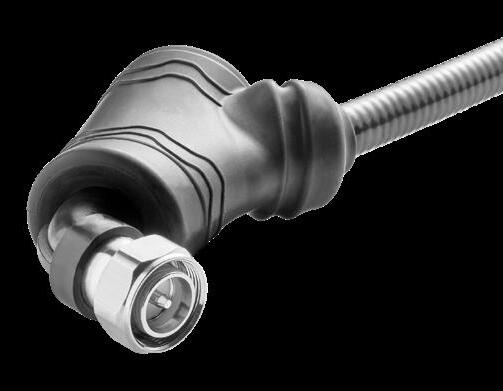
• 1/2-inch jumpers with right-angle connectors
• 1/2-inch jumpers with NEX10 connectors
The boot’s sleek, close-fitting design results in a small footprint that’s ideal to protect any connection, including connections to multi-port equipment with tight connector spacing.
UPGRADE TO FASTER, EASIER WEATHERPROOFING WITH CELLFLEX SECUREFIT BOOTED JUMPERS
With CELLFLEX SecureFit Booted Jumpers, you can quickly and easily add an additional level of sealing and strain relief to any connection with no need for installers to waste time and effort applying and removing sealing tape.
Installers can connect and disconnect our SecureFit Booted Jumpers far faster and easier than they can when sealing tape is used to protect connections. And no waste is generated, so installers never have to worry about garbage removal or clutter while they’re working high on towers. There’s also no that risk that jumper cables can be damaged or installers injured as is the case when a knife is used to remove sealing tape from connections.
ENSURE CONSISTENT AND RELIABLE WEATHERPROOFING ON ALL CONNECTIONS
The SecureFit boot design is the same no matter which connector type you’re using or which equipment you’re connecting to.
The ergonomic boot design allows installers to use a single hand to easily slide the boot into place over the connection and to remove the boot when needed. Installers quickly master the technique and can apply consistent and reliable weatherproofing across all connections with minimal training.
The lead time for CELLFLEX SecureFit Booted Jumpers is the same as our CELLFLEX Factory-Fit Jumpers, so there are no delays when booted jumpers are required.
Protect your network investment and maintain premium performance with a reliable and exceptionally easy weatherproofing solution from RFS

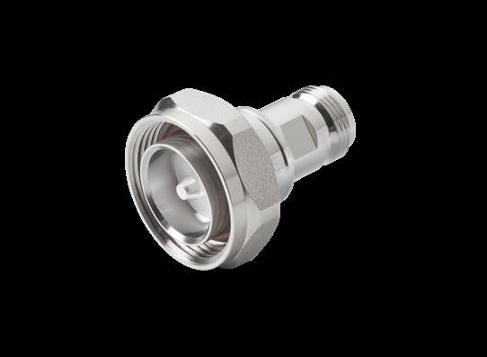
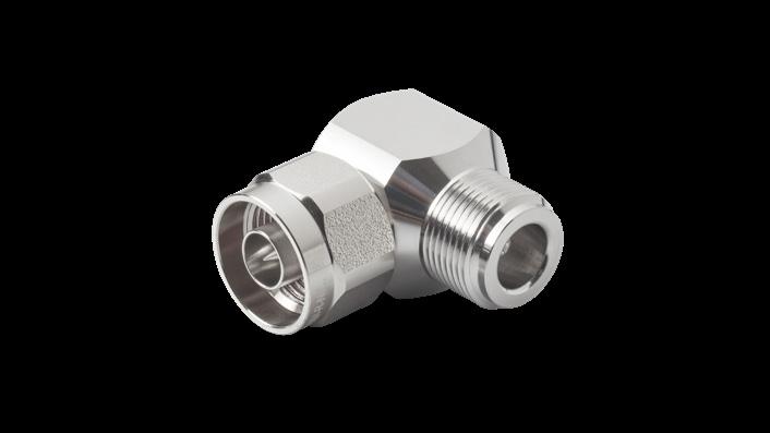
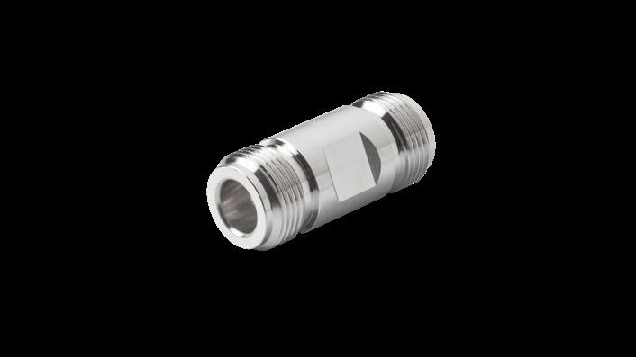
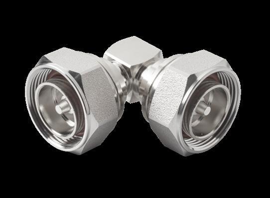
UNLIMITED CONNECTIONS WITH THE RFS ADAPTER SERIES
CONNECTIONS IN THE FIELD JUST GOT EASIER
RFS' new coaxial adapter series provides a fast, easy and cost-effective solution for jumper connections. With a large selection of both straight and right angle adapters, there is a model for every network requirement. Passive intermodulation specifications for all RFS adapters is < -163 dBc.
RFS offers a wide range of videos to make installation fast and easy:
• Install premium and standard connectors on CELLFLEX® cables of all sizes
• Install connectors onto RADIAFLEX® cables
• DragonSkin™ premium and standard connector installation
• Watch these and more on the RFS YouTube channel

MODEL NUMBER (STRAIGHT) MODEL NUMBER (RIGHT ANGLE) 716M-716F 716M-R-716F 716F-43F 716M-R-716M 716M-716M 43M-R-43F 716M-43M NM-R-NM 716M-43F NM-R-NF 716M-NM 716F-R-716F 716M-NF 716F-R-43M 43F-43F 716F-R-43F 43F-NM 716F-R-NM 43F-NF 716F-R-NF 43M-43M 716M-R-43M 43M-NM 716M-R-43F 43M-NF 716M-R-NM NM-NM 716M-R-NF NM-NF 43F-R-43F NF-NF 43F-R-NM 716F-716F 43F-R-NF 716F-43M 43M-R-43M 716F-NM 43M-R-NM 716F-NF 43M-R-NF 43M-43F NF-R-NF
20 21 Transmission Line Solutions Transmission Line Solutions