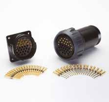
BAYONET CONNECTORS FOR RAILWAY APPLICATIONS
Bayonet Connectors with insert in Thermoplastic Resin
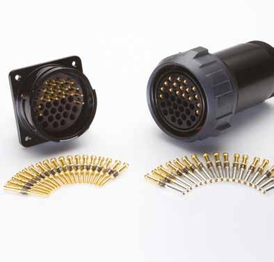
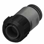
KVBS
Bayonet Connectors with insert in Thermoplastic Resin
Since 1952, Radiall Sa have been enabling the future through collaboration with our customers. The results are a range of innovative and award-winning products that customers trust for unrivaled repeatability and performance.
Radiall Sa are a global company with facilities around the world that specializes in manufacturing the highest quality interconnect components to support the most demanding applications.
At Radiall, you can rely on us to be the industry’s global market leader.
VanSystem was a company founded in Lombardy - Italy, which has been operating since 1985 in the industrial market. Since 2015 VanSystem is a Radiall company.
Besides connectors with screw or bayonet coupling complying with the Mil-DTL-5015 standard, we designs and manufactures non-standard products for special applications.
One of our’s strong points is an agile and dynamic organizational structure which enables direct and constant interaction with customers in order to meet all their requirements and build solid, long-term partnerships. Our team’s professionalism, skill and commitment are at your service to help you achieve the solution you are looking for.
Radiall Italia S.r.l. Quality System is qualified according to ISO 9001:2015 and ISO/TS 22163:2017
Advantages
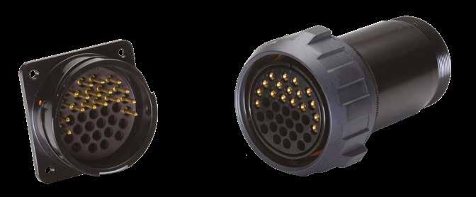
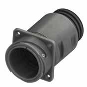
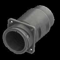
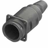
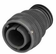
KVBS connector series derives from the RF CVBS one and it is based on Mil-DTL-5015 and VG95234 specs.
The most important advantage is the simpler and faster cable assembly.
Components materials have been chosen in order match railways vehicles requirements.
Key characteristics
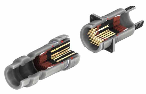
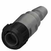
• 3 ramps reverse bayonet
• Thermoplastic contact holder and insulator
• Contacts retained by a high elasticity clip
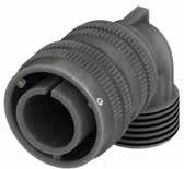
• Front grommet
• Rear side grommet supplied with holes closed by a flash of rubber and equipped with side gasket
• Reliable mating even under vibrations, shock and sealing requirements
• Simpler and faster cable assembly
• More reliable contact retention inside the insulator
• When mated guarantee a better sealing and creepage distance between the contacts
• The connector can resist to axial pressure shock, the characteristics are mantained even when it is not fileld with all the contacts
• The size 16 contact cavity has a wider internal diameter able to accept flame retardant cableup to 2.5mm2
Material and plating *
Shells
Alluminium alloy - can be protected against corrosion with the following plating process: Black epoxy varnish (not conductive) (RoHS compliance) CCF - Black passivation - conductive (RoHS compliance)
Insulators Thermoplastic resin according to UL 94 V0, flame retardant according to EN 45545-2 HL3 R22/23 (Meets NF F 16-101/NF F 16-102 standards)
Grommet and Interfacial Seal Flame retardant rubber
Contacts Copper alloy - silver or gold plated
* Different materials and platings can be used on application request.
General characteristics
Working temperature -40°C ÷ +125°C (+ 100°C according NF F 61-030)
Insulation resistance > 5.000 MΩ
IP protection degree up to IP68 (waterproof to 10 meters - 12 hours) (when mated connectors with adequate accessories)
Insulation according to NFF 61030 ***
*** Values are related to mated connectors
KVBS
- Insulating material - Thermoplastic resin
KVBS Series Code
KVBS Bayonet Connector
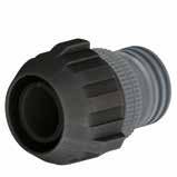
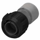
KVBSG Bayonet Connector with external insulated coating
303 Shell Material - Aluminum 303 Stainless Steel 303 316 Stainless Steel 316L
030 Shell Type xx With ramp/threaded or with nut
DA Connector Class xx With backshell
T With plastic caps
T Connector Modification**
FF Receptacle connector with threaded holes (to specify for 00/02/05 shell only)
FP Receptacle connector with through holes (to specify for 03 shell only)
GG Rubber covered nut (bayonet version only)
24-10 Insert Arrangement xx-xx Size - Arrangement
S Contact Gender
X Polarization Code**
M32 Backshell Conduits size or internal thread
LC Contact Termination
- Contact Plating
F7 Shell finishes
G Panel Gasket
N101 Modification Code**
** If required
S Socket contacts
P Pin contacts
- No rotation W,X,Y,Z,Q Rotation
- Without internal thread xx Conduits size or internal thread
- Crimp contacts (pages 100/101)
LC Less contacts
- Silver plating
CD5 Gold plating
CDN Gold plating NPGR
F7 Black epoxy varnish (RoHS compliance)
F12 Black Hard Deep Anodization (not conductive) high treatment thickness (RoHS compliance)
F16 CCF - Black passivation - conductive (RoHS compliance)
F26 Black Hard Anodization (RoHS compliance)
F30 colorless passivation for stainless steel (RoHS compliance)
- Without gasket
G With waterproof panel gasket
G3 With waterproof shielded panel gasket
Nxx Contacts and hole plugs (Consult our sales office)
Sxx Customization (Consult our sales office)
FF FP FS
Shell Type with ramp
Shell 030 Rear mounting receptacle connector with thread to accept backshells
- - - Shell 01 In-line receptacle able to accept rear accessories.
9 1
Shell Type with coupling nut
Shell 06 Plug connector, for straight backshell
Shell 61 Plug connector, for straight backshell, coupling nut rubber covered (short version)
Shell 06GG Plug connector, for straight backshell with rubber covered coupling nut
Shell 96 Plug connector, provided with grounding finger - with straight backshell
Shell 96GG Plug connector, provided with grounding finger - with straight backshell - with rubber covered coupling nut
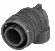
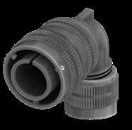
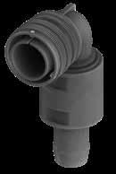
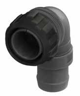
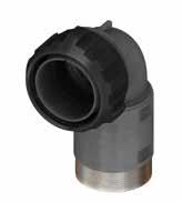
Shell 08 Plug connector, with 90° elbow
Shell 81 Plug connector, with 90° elbow, coupling nut rubber covered (short version)
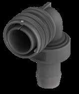
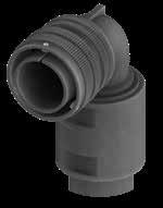
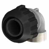
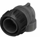
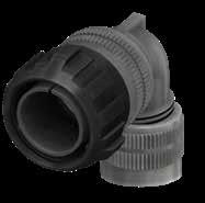
Shell 08GG Plug connector, with 90° elbow with rubber covered coupling nut
Shell 98 Plug connector, with 90° elbow, with grounding finger
Shell 98GG Plug connector, with 90° elbow, with grounding finger with rubber covered coupling nut
Shell 961 Plug connector, provided with grounding finger - with straight backshell, coupling nut rubber covered (short version)
Shell 981 Plug connector, provided with grounding finger - with 90° elbow, coupling nut rubber covered (short version)
Avalaible 9 = with grounding finger 1 = rubber covered coupling nut, short version
With waterproof O-ring and Grommet Connector
Without O-ring and Grommet (non-watertight)
With waterproof O-ring
1 2 3
Connector Class - backshell
- A DA RA Backshell having an external thread suitable for MS3057…A or C type cable-clamps
- SA SDA SRA Short Backshell having an external thread suitable for MS3057…A or C type cable-clamps
DA..M RA..M Provided with an internal Metric thread
- R Suitable to connect single wires (when strain relief is not necessary)
- AST ST Backshell with internal cable retention system (on request ST1/ST2 with clamps for cable diameter reduction) with an external unef thread
- AST..M ST..M Backshell with internal cable retention system (on request ST1/ST2 with clamps for cable diameter reduction) with an internal Metric thread
- AST..FS ST..FS Backshell with internal cable retention system (on request ST1/ST2 with clamps for cable diameter reduction) with a special adapter for UNI4883 rubber conduits
- DA..FS RA..FS Provided with a special adapter for UNI4883 rubber conduits
VanSystem is able to offer connectors with 11 Arrangements manufactured in Thermoplastic material.
The connectors is supplied with inferfacial seal to guarantee fhe sealing of mating over the entire area of the Interface and around each contact.
Available in several versions suitable for all applications and manufactured in different materials and finishes:
• Aluminum alloy with different types of protection finishes according to RoHS directives.
• Stainless steel, brass nickel plated and other materials to be chosen according to the application
• Coupling nut in bayonet version
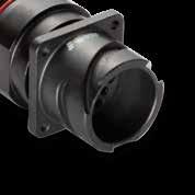
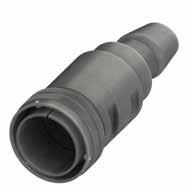
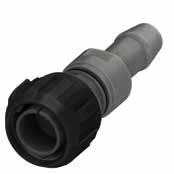
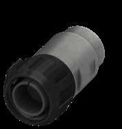
The bayonet connectors provide faster coupling and anti-vibration resistance.
In the KVBS serie the coupling system is composed of 3 bayonet ramps machined on the external side of the receptacle connector and 3 stainless steel studs mounted inside the plug connector’s coupling nut.
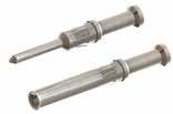
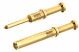
Available in crimp, machined copper alloys and finished with gold or silver platings.
All contacts are manufactured in order to guarantee optimum connection properties and to provide resistance to vibration and continuous mating and unmating cycles.
This series, deriving from Mil-DTL-5015 and VG95234 specs, has become a popular standard among railway connection applications. The coupling point at the end of the ramp is protected by a stainless steel roller able to increase the number of mating cycles.
Main characteristics:
• Fast and reliable coupling (coupling-nut rotation of 120° only and mating is audible, visible and tactile)
• Vibration and impact resistance
• Manufactured in several shell versions as panel connectors (with front or rear mounting) or plug connectors (with straight backshell or 90°)
• Accessories for all types of cables and shielding protection hoses are also available
• Crimp contacts are suitable for wires of many sections
Advantages:
• Faster coupling, continuous and reliable service in the harshest use conditions
• Wave washer installed under the plug connector coupling nut
• IP68 waterproof protection (when connectors are mated and harnessed by using the correct accessories)

• MIL-DTL-5015: Connectors, Electrical, Circular threaded, an type, general specification for
• SAE AS 39029: Contacts, Electrical Connectors, general specification for
• VG 95234: Electrical connectors with bayonet coupling pressure-water tight, up to 245A
• EN 50124-1: Railway applications - Insulation coordination
• IEC 60077-1: Railway applications - Electric equipment for rolling stock
• EN 45545-2: Railway applications - Fire protection on railway vehicles
• NFPA 130 (ASTM E 162, ASTM E 662): Standard for Fixed Guideway Transit and Passenger Rail Systems
• UNI CEI 11170-3 : Guidelines for railway vehicle protection for tramways and with guided rail
• NFF 16-102: Railway Rolling Stock - Fire Behavior
• EN 50467: Railway applications - Rolling stock - Electrical connectors, requirements and test methods
• IEC 61373: Railway applications. Rolling stock equipment. Shock and vibration tests
• IEC 60529: Degrees of protection provided by enclosures (IP Code)
• European Directive 2011/65: RoHS complying
Features and Benefits
Robust Connection
• Fully protected connectors: no risk to damage the contacts thanks the robust shell
• Supplied with grounding finger, conductive plating and the proper rear accessory
• Suitable for polarizations to prevent un-correct coupling
Easy installation
• Fast and reliable coupling
• Backshell and accessories for fastening cable/conduit fixation
Suitable for harsh environments (adapted for outdoor use)
• Waterproof connection
• Dust proof
• Corrosion resistant
High level of performance
• Working temperature -40°C ÷ 125°C (according to the inserts material)
• EMI protection with grounding finger
• Power connection up to 73A
APPLICATIONS
• Railway
• Energy
• Naval
• Industrial
Plug connectors with grounding finger (type 96 - 98 - 96GG - 98GG) when mated with receptacle connectors (type 030) and provided with rear accessories for shielded cables have shielding characteristics according to VG95234 specs.
F16 Shell Finishes is recommended for electrical conductivity from receptacle to plug.
VG95234 specs: Shielding effectiveness data over frequency range (with conductive shells)
Shells
They are manufactured in aluminum alloy or stainless steel and can be protected against corrosion by the following finishes (Halogen-free):
• F7 : Black epoxy varnish (not conductive) - complies RoHS directives(*)
• F12 : Black Hard Deep Anodization (not conductive) - complies RoHS directives(*)
• F16 : CCF-Black passivation (conductive) - complies RoHS directives(*)
• F26 : Hard anodization (RoHS compliance)
• F30 : Colorless passivation for stainless steel (for AISI 303 and AISI 304. Without passivation for AISI 316L)
(*) Restriction of Hazardous Substances Directives of the European Parliamentn°2002/95/ECissued on 27 January 2003 Alternative materials and finishes are available to suit specific requirements.
Surface Treatment Code
Shell-material Aluminium alloy Stainless Steel
Surface finish epoxypolyurethan Hard Deep anodization CCF cadmiun free Hard anodization Colorless
Type of surface varnished passivated passivated passivated passivated
Surface colour black black black black -
Rohs
Electrical conductivity non-conductive non-conductive good non-conductive good
Shock and vibrations tests according EN 61373 Cat. 1 body mounted Cat. 2 bogie mounted Cat. 2 bogie mounted Cat. 2 bogie mounted Cat. 2 bogie mounted
IP protection degree (EN 60529) IP54, IP67, IP68 (waterproof to 10 meters - 12 hours) when used with proper backshell or accessories
** Consult our sales office
*** 200h in case of components, panel and screws in stainless steel (galvanic corrosion)
Mechanical Characteristics
Coupling mechanism
Reverse Bayonet Connector Mating endurance (IEC 61300-2-2)
Shock and vibrations tests (EN 61373)
500 mating cycles minimum (for use up to 2000 mating cycles, consult our commercial office)
Category 1 body mounted Category 2 bogie mounted
The values mentioned below are valid for usage at 20°C ambient temperature. Let us remind you that:
• when temperatures rise, the conductivity of the contacts and therefore the value of the applicable current decreases
• at the operating current and 20°C ambient temperature the connection temperature increases anyway
• in consequence to all of the above, the current applicable to a given temperature and a determined contact size must be carefully considered
The material of the insert must be chosen to comply with both room temperature and the one produced by the electrical connection.
If in doubt we suggest you consult our Sales Office.
Rated current with one contact loaded in a contact arrangement.
* Valid for ambient temperature at 20°C.
** Test according to SAE AS39029 with silver plated wire.
*** Valid for ambient temperature at 80°C.
The values of the following table:
• are valid for usage at sea level
• refer to a clean environment of application. The pollution due to metallic or other impurities has to be taken into consideration.
• concern contacts with standard termination, solder or crimping, with size suitable for AWG section wires matching the relevant contact size. It is therefore necessary to pay attention when using contacts with crimp termination bigger than the nominal AWG size.
* The connectors do not show any sign of breakdown when the voltage indicated in the table is applied for one minute between the two closest contacts and between the shell and the contact closest to the shell.
Caution : When nominal operating voltage exceeds 50V towards earth, the appropriate safety measures have to be adopted as described by CEI 23, IEC 309-1, BS 2618, VDE 0100 specs. The data shown on the above table are applicable only when the above mentioned safety rules are fulfilled.
**** according MIL-DTL-5015 spec
assembly instructions.
Recommended current according to the temperature.
Rated current with one contact loaded in a contact arrangement.
Electrical design and production parameters of threaded or bayonet coupling connectors are derived from Mil-DTL-5015 and VG 95234 standards. All circular connectors are produced and tested in accordance of VG 95234 standards.
They are machined in high conductivity copper alloy in order to guarantee optimum connection properties and to provide resistance to vibration and continuous mating and unmating cycles.
They are protected by a silver (standard production) or gold finish with varying plating thickness on request.
As for connector codes to be supplied with specific finish contacts please consult the section referring to the P/N explanations on page 4.
Contacts for particular applications, alternative termination types and with special finishes are available to suit specific requirements.
Engagement and disengagement force between contacts
* Acc. To NF F 61-030. Max heating allowed: 50°C Single Contact: loaded into insulator. - Grouped Contacts: fully populated insulator,all contacts loaded.
* Test according to SAE AS39029
The following table lists the possible available positions for each arrangement.
When more than one connector with the same arrangement is mounted on the same panel, it is advisable to orientate the connector This means to rotate the insert with respect to the polarization key so that the connector can only be mated with the correct mating half.
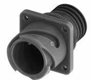
KVBS - Bayonet Connector with protected mating ramps
Rear Mounting Receptacle (030) with Backshell Class (A - DA - RA)
Connector with backshell provided with an external thread suitable for MS3057…A or C type cable-clamps (to be ordered separately).
Dimension “L” can be different from the value indicated according to backshells accessories, wires size and some special insert configurations. Dimensions in mm
Series Code Shell Type Connector Class Shell finish
Insulating material - Thermoplastic resin
KVBS Series Code KVBS Bayonet Connector with protected mating ramps
Shell Material - Aluminum
S Contact Gender S Socket contacts P Pin contacts X Polarization Code** Page 14
LC Contact Termination LC Less contactsContact Plating - Silver plating
non watertight
030 Shell Type 030 Rear mounting Receptacle DA Connector Class
with waterproof O-ring (IP67***)
with waterproof O-ring and grommet (IP67***)
T Connector Modification**
With plastic capsReceptacle connector with threaded holes
Receptacle connector with through holes
24-10 Insert Arrangement Page 14
CD5 Gold plating F7 Shell finish
F7 Black epoxy varnish (*)
F16
CCF - Black passivation (*) - conductive
F26 hard anodization (*) G Panel Gasket
Without gasket G With waterproof panel gasket
G3 With waterproof shielded panel gasket
Modification Code**
degree: IP 67 (only in the mating area with mated connectors) according to EN 60529
Consult our sales office
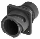
KVBS - Bayonet Connector with protected mating ramps
Rear Mounting Receptacle (030) with Backshell Class (SA - SDA - SRA)
Connector with short backshell provided with an external thread suitable for MS3057…A or C type cable-clamps (to be ordered separately).
cut out
Consult our sales office
Dimension “L” can be different from the value indicated according to backshells accessories, wires size and some special insert configurations.
Series Code Shell Type Connector Class Shell finish
Insulating material - Thermoplastic resin
KVBS Series Code KVBS Bayonet Connector with protected mating ramps
Shell Material - Aluminum
030 Shell Type 030 Rear mounting Receptacle
SA non watertight
SDA Connector Class
T Connector Modification**
SDA with waterproof O-ring (IP67***)
SRA with waterproof O-ring and grommet (IP67***)
T With plastic caps
Receptacle connector with threaded holes
FP Receptacle connector with through holes
24-10 Insert Arrangement Page 14
S Contact Gender S Socket contacts P Pin contacts
X Polarization Code** Page 14
LC Contact Termination
Contact Plating
LC Less contacts
- Silver plating
CD5 Gold plating F7 Shell finish
F7 Black epoxy varnish (*)
F16
G Panel Gasket
CCF - Black passivation (*) - conductive
F26 hard anodization (*)
- Without gasket
G With waterproof panel gasket
G3 With waterproof shielded panel gasket N Modification Code**
Protection degree: IP 67 (only in the mating area with mated connectors) according to EN
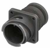
KVBS - Bayonet Connector with protected mating ramps
Rear Mounting Receptacle (030) with Backshell Class (DA..M - RA..M)
Connector with backshell provided with an internal Metric thread suitable for cable glands or conduit adapters.
On Request
“L” can be different from the value indicated according to backshells accessories, wires size and some special insert configurations.
Series Code Shell Type Connector Class Shell finish
Backshell internal thread
Grommet cone (RA..M Class only)
Grommet (RA..M Class only) Gasket
Insulating material - Thermoplastic resin
KVBS Series Code KVBS Bayonet Connector with protected mating ramps
Shell Material - Aluminum
030 Shell Type 030 Rear mounting Receptacle
DA Connector Class DA with waterproof O-ring (IP67***) RA with waterproof O-ring and grommet (IP67***)
T Connector Modification** T With plastic capsReceptacle connector with threaded holes FP Receptacle connector with through holes
24-10 Insert Arrangement Page 14
S Contact Gender S Socket contacts P Pin contacts
P/N
X Polarization Code** Page 14
M20 Backshell internal thread Mxx Provided with an internal Metric thread
LC Contact Termination
Contact Plating
F7 Shell finish
LC Less contacts
- Silver plating
CD5 Gold plating
F7 Black epoxy varnish (*)
F16
CCF - Black passivation (*) - conductive
F26 hard anodization (*)
G Panel Gasket - Without gasket G With waterproof panel gasket
G3 With waterproof shielded panel gasket
N Modification Code** N Consult our sales office S
KVBS - Bayonet Connector with protected mating ramps Rear Mounting Receptacle (030) with Backshell Class (DA...FS - RA...FS)
Connector with special adapter for UNI4883 rubber conduits. Conduit’s size must be specified adding the diameter dimensions in the P/N (i.e.: KVBS 030DA…FS5040…).
Panel cut out
* For installation with backshell mounted, consult our sales office.
Rubber Conduit not included
Consult our sales office
Dimensions
Dimension “L” can be different from the value indicated according to backshells accessories, wires size and some special insert configurations.
Series Code Shell Type Connector Class Shell finish
The accessories for this class are not always available in stock for all sizes; we suggest you consult our Sales Office for availability Insulating material - Thermoplastic resin
KVBS Series Code KVBS Bayonet Connector with protected mating ramps
030 Shell Type
DA Connector Class
Rear mounting Receptacle
with waterproof O-ring (IP67***)
with waterproof O-ring and grommet (IP67***) T Connector Modification**
With plastic capsReceptacle connector with threaded holes
Receptacle connector with through holes
24-10 Insert Arrangement Page 14
S Contact Gender S Socket contacts P Pin contacts X Polarization Code** Page 14 FS.. Backshell Conduits size
Provided with a special adapter for UNI4883 rubber conduits
LC Contact Termination
Less contactsContact Plating
Silver plating CD5 Gold plating F7 Shell finish
F7 Black epoxy varnish (*)
F16 CCF - Black passivation (*) - conductive
F26 hard anodization (*) G Panel Gasket - Without gasket G With waterproof panel gasket G3 With waterproof shielded panel gasket N Modification Code**
Consult our sales office
KVBS - Bayonet Connector with protected mating ramps
Rear Mounting Receptacle (030) with Backshell Class (R)
This class is suitable to connect single wires when strain relief is not necessary and small longitudinal overall dimensions are needed. As watertightness is guaranteed by the grommet only, it is necessary to make sure the wire diameter matches the grommet sealing range.
Series Code Shell Type Connector Class Shell finish
The accessories for this class are not always available in stock for all sizes; we suggest you consult our Sales Office for availability Backshell Grommet cone Grommet Gasket
Insulating material - Thermoplastic resin
KVBS Series Code KVBS Bayonet Connector with protected mating ramps
Shell Material - Aluminum
030 Shell Type 030 Rear mounting Receptacle
R Connector Class R With O-ring and grommet
T With plastic caps
T Connector Modification**
Receptacle connector with threaded holes
FP Receptacle connector with through holes
24-10 Insert Arrangement Page 14
S Contact Gender
S Socket contacts
P Pin contacts
X Polarization Code** Page 14
LC Contact Termination
Contact Plating
F7 Shell finish
G Panel Gasket
LC Less contacts
- Silver plating
CD5 Gold plating
F7 Black epoxy varnish (*)
F16
CCF - Black passivation (*) - conductive
F26 hard anodization (*)
- Without gasket
G With waterproof panel gasket
G3 With waterproof shielded panel gasket
N Modification Code** N
Consult our sales office S
(*) RoHS compliance (**) If required
KVBS - Bayonet Connector with protected mating ramps
Rear Mounting Receptacle (030) with Backshell Class (AST - ST)
Connector with backshell with internal cable retention system (on request ST1/ST2 with clamps for cable diameter reduction) with an external unef thread
Series Code Shell Type Connector Class Shell finish
Adapter (AST1 - ST1 - AST2 -ST2 Class only)
KVBS 030 ST 24-10 S X LC F7 G N T Metal Adapter
Grommet cone (ST - ST1 - ST2 Class only)
Insulating material - Thermoplastic resin
KVBS Series Code KVBS Bayonet Connector with protected mating ramps
Shell Material - Aluminum
030 Shell Type 030 Rear mounting Receptacle
AST with waterproof O-ring (IP67***)
ST with waterproof O-ring and grommet (IP67***)
ST Connector Class
T Connector Modification**
AST1 with waterproof O-ring (IP67***)
ST1 with waterproof O-ring and grommet (IP67***)
AST2 with waterproof O-ring (IP67***)
ST2 with waterproof O-ring and grommet (IP67***)
T With plastic caps
Receptacle connector with threaded holes
FP Receptacle connector with through holes
24-10 Insert Arrangement Page 14
S Contact Gender S Socket contacts P Pin contacts
X Polarization Code** Page 14
LC Contact Termination
Contact Plating
F7 Shell finish
G Panel Gasket
LC Less contacts
- Silver plating
CD5 Gold plating
F7 Black epoxy varnish (*)
F16 CCF - Black passivation (*) conductive
F26 hard anodization (*)
- Without gasket
G With waterproof panel gasket
G3 With waterproof shielded panel gasket
N Modification Code** N
*** Protection degree: IP 67 (only in the mating area with mated connectors) according to EN 60529
Grommet (ST - ST1 - ST2 Class only) Gasket (*) RoHS compliance (**) If required
Consult our sales office S
P/N Sample: KVBS 030STT 24-10SX LC F7 G N
KVBS - Bayonet Connector with protected mating ramps
Rear Mounting Receptacle (030) with Backshell Class (AST..M - ST..M)
Connector with backshell with internal cable retention system (on request ST1/ST2 with clamps for cable diameter reduction) with an internal Metric thread
Series
Backshell internal thread
Adapter (AST1 - ST1 - AST2 -ST2 Class only)
Grommet (ST - ST1 - ST2 Class only) Gasket
Grommet cone (ST - ST1 - ST2 Class only)
Insulating material - Thermoplastic resin
KVBS Series Code KVBS Bayonet Connector with protected mating ramps
Shell Material - Aluminum
030 Shell Type 030 Rear mounting Receptacle
AST with waterproof O-ring (IP67***)
ST with waterproof O-ring and grommet (IP67***)
ST Connector Class
T Connector Modification**
AST1 with waterproof O-ring (IP67***)
ST1 with waterproof O-ring and grommet (IP67***)
AST2 with waterproof O-ring (IP67***)
ST2 with waterproof O-ring and grommet (IP67***)
T With plastic capsReceptacle connector with threaded holes
FP Receptacle connector with through holes
P/N Sample: KVBS 030STT 24-10SX M20 LC F7 G N
24-10 Insert Arrangement
Metal Adapter
Page 14
S Contact Gender S Socket contacts P Pin contacts X Polarization Code** Page 14
M20 Backshell internal thread Mxx Provided with an internal Metric thread
LC Contact Termination LC Less contacts
Contact Plating - Silver plating
F7 Shell finish
G Panel Gasket
CD5 Gold plating
F7 Black epoxy varnish (*)
F16
CCF - Black passivation (*) conductive
F26 hard anodization (*)
- Without gasket
G With waterproof panel gasket
G3 With waterproof shielded panel gasket
N Modification Code** N
Consult our sales office S
KVBS - Bayonet Connector with protected mating ramps
Rear Mounting Receptacle (030) with Backshell Class (AST..FS - ST..FS)
Connector with backshell with internal cable retention system (on request ST1/ST2 with clamps for cable diameter reduction) with a special adapter for UNI4883 rubber conduits
cut out * On request (please consult our Sales Office) Rubber Conduit not included
Please consult our Sales Office for further details about this dimension and according to conduit size.
Series Code Shell Type Connector Class
Adapter (AST1 - ST1 - AST2 -ST2 Class only)
Backshell Conduits size Shell finish
Grommet (ST - ST1 - ST2 Class only)
Grommet cone (ST - ST1 - ST2 Class only)
Insulating material - Thermoplastic resin
KVBS Series Code KVBS Bayonet Connector with protected mating ramps
Shell Material - Aluminum
030 Shell Type
030 Rear mounting Receptacle
AST with waterproof O-ring (IP67***)
ST with waterproof O-ring and grommet (IP67***)
ST Connector Class
T Connector Modification**
AST1 with waterproof O-ring (IP67***)
ST1 with waterproof O-ring and grommet (IP67***)
AST2 with waterproof O-ring (IP67***)
ST2 with waterproof O-ring and grommet (IP67***)
T With plastic caps
Receptacle connector with threaded holes
FP Receptacle connector with through holes
24-10 Insert Arrangement Page 14
S Contact Gender
adapter
S Socket contacts
P Pin contacts
X Polarization Code** Page 14
FS Backshell Conduits size
FS
Provided with a special adapter for UNI4883 rubber conduits xxxx Conduit Size xxxx ØA1ØA2
LC Contact Termination
LC Less contactsContact Plating - Silver plating
CD5 Gold plating
F7 Shell finish
G Panel Gasket
RoHS compliance (**) If required *** Protection degree: IP 67 (only in the mating area with mated connectors) according to EN 60529 Gasket
P/N Sample: KVBS 030STT 24-10SX
F7 Black epoxy varnish (*)
F16 CCF - Black passivation (*) conductive
F26 hard anodization (*)
- Without gasket
G With waterproof panel gasket
G3 With waterproof shielded panel gasket
N Modification Code** N
Consult our sales office S
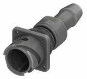
KVBS - Bayonet Connector with protected mating ramps
Plug Connector (06/96) with Backshell Class (A - DA - RA)
Connector with backshell provided with an external thread suitable for MS3057…A or C type cable-clamps (to be ordered separately).
Grounding finger for Shell 96
Dimension “L” can be different from the value indicated according to backshells accessories, wires size and some special insert configurations. Dimensions
Backshell Grommet cone (RA Class only) Grommet (RA Class only)
(DA-RA Class only)
Insulating material - Thermoplastic resin
KVBS Series Code KVBS Bayonet Connector with protected mating ramps
Shell Material - Aluminum 06 Shell Type 06 Plug Connector without grounding finger 96 Plug Connector with grounding finger DA Connector Class
non watertight
with waterproof O-ring (IP67***)
with waterproof O-ring and grommet (IP67***)
T Connector Modification** T With plastic caps
P/N Sample: KVBS 06DAT 24-10SX LC F7 N
24-10 Insert Arrangement Page 14 S Contact Gender S Socket contacts P Pin contacts X Polarization Code** Page 14
LC Contact Termination LC Less contactsContact Plating - Silver plating
CD5 Gold plating
F7 Black epoxy varnish (*)
F7 Shell finish
F16
CCF - Black passivation (*) - conductive
F26 hard anodization (*) N Modification Code**
Consult our sales office
KVBS - Bayonet Connector with protected mating ramps
Plug Connector (06/96) with Backshell Class (SA - SDA - SRA)
Connector with short backshell provided with an external thread suitable for MS3057…A or C type cable-clamps (to be ordered separately).
Dimensions in mm
Grounding finger for Shell 96 * On request (please consult our Sales Office)
Dimension “L” can be different from the value indicated according to backshells accessories, wires size and some special insert configurations.
Series Code Shell Type Connector Class Shell finish
Backshell Grommet cone (RA Class only) Grommet (RA Class only)
(DA-RA Class only)
Insulating material - Thermoplastic resin
KVBS Series Code KVBS Bayonet Connector with protected mating ramps
Shell Material - Aluminum
06 Shell Type 06 Plug Connector without grounding finger 96 Plug Connector with grounding finger
SDA Connector Class SA non watertight SDA with waterproof O-ring (IP67***) SRA with waterproof O-ring and grommet (IP67***)
T Connector Modification** T With plastic caps
P/N Sample: KVBS 06SDAT 24-10SX LC F7 N
24-10 Insert Arrangement Page 14
S Contact Gender S Socket contacts P Pin contacts X Polarization Code** Page 14
LC Contact Termination LC Less contactsContact Plating - Silver plating
CD5 Gold plating
F7 Black epoxy varnish (*)
F7 Shell finish
F16
CCF - Black passivation (*) - conductive
F26 hard anodization (*)
N Modification Code** N Consult our sales office S
KVBS - Bayonet Connector with protected mating ramps
Plug Connector (06/96) with Backshell Class (DA..M - RA..M)
Connector with backshell provided with an internal Metric thread suitable for cable glands or conduit adapters.
Grounding finger for Shell 96
Dimension “L” can be different from the value indicated according to backshells accessories, wires size and some special insert configurations.
Code Shell Type Connector Class
Grommet cone (RA..M Class only) Grommet (RA..M Class only)
Insulating material - Thermoplastic resin
KVBS Series Code KVBS Bayonet Connector with protected mating ramps
Shell Type
Plug Connector without grounding finger
Plug Connector with grounding finger
contacts
Pin contacts
Polarization Code** Page 14
Backshell internal thread
Provided with an internal Metric thread LC Contact Termination
Contact Plating
Less contacts
plating
plating
F7 Black epoxy varnish (*) F16 CCF - Black passivation (*) - conductive
F26 hard anodization (*)
KVBS - Bayonet Connector with protected mating ramps
Plug Connector (06/96) with Backshell Class (DA..FS - RA..FS)
Connector with special adapter for UNI4883 rubber conduits. Conduit’s size must be specified adding the diameter dimensions in the P/N (i.e.: KVBS 06DA…FS5040…).
Grounding finger for Shell 96
Rubber Conduit not included
Please consult our Sales Office for further details about this dimension and according to conduit size.
* On request (please consult our Sales Office)
3328
Series Code Shell Type Connector Class
Backshell Conduits size Shell finish
Grommet (RA..FS Class only)
Backshell Grommet cone (RA..FS Class only)
Gasket Metal Adapter Gasket
The accessories for this class are not always available in stock for all sizes; we suggest you consult our Sales Office for availability
Insulating material - Thermoplastic resin
KVBS Series Code KVBS Bayonet Connector with protected mating ramps
Shell Material - Aluminum 06 Shell Type 06 Plug Connector without grounding finger 96 Plug Connector with grounding finger
DA Connector Class DA with waterproof O-ring (IP67***)
RA with waterproof O-ring and grommet (IP67***)
T Connector Modification** T With plastic caps
24-10 Insert Arrangement Page 14
S Contact Gender S Socket contacts
P Pin contacts
X Polarization Code** Page 14
FS Backshell Conduits size FS
Provided with a special adapter for UNI4883 rubber conduits 3328 Conduit Size xxxx ØA1ØA2
LC Contact Termination LC Less contactsContact Plating - Silver plating
F7 Shell finish
CD5 Gold plating
F7 Black epoxy varnish (*)
F16
CCF - Black passivation (*) conductive
F26 hard anodization (*) N Modification Code** N
Consult our sales office S
RoHS compliance (**) If required *** Protection degree: IP 67 (only in the mating area with mated connectors) according to EN 60529
Sample:
This class is suitable to connect single wires when strain relief is not necessary and small longitudinal overall dimensions are needed. As watertightness is guaranteed by the grommet only, it is necessary to make sure the wire diameter matches the grommet sealing range. Grounding finger for Shell 96
Dimensions in mm
Dimension “L” can be different from the value indicated according to backshells accessories, wires size and some special insert configurations.
Series Code Shell Type Connector Class Shell finish
The accessories for this class are not always available in stock for all sizes; we suggest you consult our Sales Office for availability Backshell Grommet cone Grommet Gasket
Insulating material - Thermoplastic resin
KVBS Series Code KVBS Bayonet Connector with protected mating ramps
Shell Material - Aluminum 06 Shell Type 06 Plug Connector without grounding finger 96 Plug Connector with grounding finger
R Connector Class R With O-ring and grommet
T Connector Modification** T With plastic caps
24-10 Insert Arrangement Page 14 S Contact Gender S Socket contacts P Pin contacts X Polarization Code** Page 14 LC Contact Termination LC Less contacts
Contact Plating
Silver plating CD5 Gold plating F7 Shell finish
F7 Black epoxy varnish (*) F16 CCF - Black passivation (*) - conductive F26 hard anodization (*) N Modification Code** N Consult our sales office S
KVBS - Bayonet Connector with protected mating ramps
Plug Connector (06/96) with Backshell Class (AST - ST)
Connector with backshell with internal cable retention system (on request ST1/ST2 with clamps for cable diameter reduction) with an external unef thread
Grounding finger for Shell 96
“L”
Series Code
Adapter (AST1 - ST1 - AST2 -ST2 Class only)
Grommet (ST - ST1 - ST2 Class only)
Grommet cone (ST - ST1 - ST2 Class only)
Insulating material - Thermoplastic resin
KVBS Series Code KVBS Bayonet Connector with protected mating ramps Shell Material - Aluminum 06 Shell Type 06 Plug Connector without grounding finger
96 Plug Connector with grounding finger
AST with waterproof O-ring (IP67***)
ST with waterproof O-ring and grommet (IP67***)
ST Connector Class
AST1 with waterproof O-ring (IP67***)
ST1 with waterproof O-ring and grommet (IP67***)
AST2 with waterproof O-ring (IP67***)
ST2 with waterproof O-ring and grommet (IP67***)
T Connector Modification** T With plastic caps
P/N Sample: KVBS 06STT 24-10SX LC F7 N
24-10 Insert Arrangement Page 14 S Contact Gender S Socket contacts P Pin contacts X Polarization Code** Page 14 LC Contact Termination LC Less contactsContact Plating - Silver plating
CD5 Gold plating
F7 Black epoxy varnish (*)
F7 Shell finish
F16 CCF - Black passivation (*) conductive
F26 hard anodization (*) N Modification Code** N Consult our sales office S
KVBS - Bayonet Connector with protected mating ramps
Plug Connector (06/96) with Backshell Class (AST..M - ST..M)
Connector with backshell with internal cable retention system (on request ST1/ST2 with clamps for cable diameter reduction) with an internal Metric thread
Grounding finger for Shell 96
Adapter (AST1 - ST1 - AST2 -ST2 Class only)
Grommet (ST - ST1 - ST2 Class only)
Grommet cone (ST - ST1 - ST2 Class only)
Insulating material - Thermoplastic resin
KVBS Series Code KVBS Bayonet Connector with protected mating ramps
Shell Material - Aluminum 06 Shell Type 06 Plug Connector without grounding finger 96 Plug Connector with grounding finger
AST with waterproof O-ring (IP67***)
ST with waterproof O-ring and grommet (IP67***)
AST1 with waterproof O-ring (IP67***)
ST Connector Class
P/N Sample: KVBS 06STT 24-10SX M20 LC F7 N KVBS 06 ST 24-10 S
ST1 with waterproof O-ring and grommet (IP67***)
AST2 with waterproof O-ring (IP67***)
ST2 with waterproof O-ring and grommet (IP67***)
T Connector Modification** T With plastic caps
Backshell internal thread Metal Adapter
24-10 Insert Arrangement Page 14 S Contact Gender S Socket contacts
Pin contacts
Polarization Code** Page 14 M20 Backshell internal thread
Provided with an internal Metric thread LC Contact Termination LC Less contacts - Contact Plating - Silver plating
CD5 Gold plating F7 Shell finish
F7 Black epoxy varnish (*)
F16
CCF - Black passivation (*) conductive
F26 hard anodization (*) N Modification Code** N
Consult our sales office
KVBS - Bayonet Connector with protected mating ramps
Plug Connector (06/96) with Backshell Class (AST..FS - ST..FS)
Connector with backshell with internal cable retention system (on request ST1/ST2 with clamps for cable diameter reduction) with a special adapter for UNI4883 rubber conduits
Grounding finger for Shell 96
Please consult our Sales Office for further details about this dimension and according to conduit size.
On
“L” can be different from the value indicated according to backshells accessories, wires size and some special insert configurations.
KVBS 06 ST 24-10 S X LC F7 N T
Series Code Shell Type Connector Class
Adapter (AST1 - ST1 - AST2 -ST2 Class only)
Grommet (ST - ST1 - ST2 Class only)
Grommet cone (ST - ST1 - ST2 Class only)
Insulating material - Thermoplastic resin
KVBS Series Code KVBS Bayonet Connector with protected mating ramps
Shell Material - Aluminum
06 Shell Type 06 Plug Connector without grounding finger 96 Plug Connector with grounding finger
AST with waterproof O-ring (IP67***)
ST with waterproof O-ring and grommet (IP67***)
ST Connector Class
AST1 with waterproof O-ring (IP67***)
ST1 with waterproof O-ring and grommet (IP67***)
AST2 with waterproof O-ring (IP67***)
ST2 with waterproof O-ring and grommet (IP67***)
T Connector Modification** T With plastic caps
xxxx
Backshell Conduits size Shell finish
Metal adapter
24-10 Insert Arrangement Page 14 S Contact Gender S Socket contacts P Pin contacts
X Polarization Code** Page 14
FS Backshell Conduits size FS
xxxx Conduit Size xxxx ØA1ØA2
LC Contact Termination LC Less contacts
- Contact Plating - Silver plating
F7 Shell finish
Gasket (*) RoHS compliance (**) If required *** Protection degree: IP 67 (only in the mating area with mated connectors) according to EN 60529 Gasket
P/N Sample: KVBS 06STT 24-10SX FS2015 LC F7 N
Provided with a special adapter for UNI4883 rubber conduits
CD5 Gold plating
F7 Black epoxy varnish (*)
F16 CCF - Black passivation (*) conductive
F26 hard anodization (*)
N Modification Code** N Consult our sales office S
Plug Connector with rubber covered coupling nut (06..GG - 61..GG - 96..GG - 961..GG) with Backshell Class (A - DA - RA)
Connector with backshell provided with an external thread suitable for MS3057…A or C type cable-clamps (to be ordered separately). Rubber covered coupling nut able to protect against dust and impact.
Grounding finger for Shell 96/961
Dimension “L” can be different from the value indicated according to backshells accessories, wires size and some special insert configurations. Dimensions
Insulating material - Thermoplastic resin
KVBS Series Code KVBS Bayonet Connector with protected mating ramps
Shell Material - Aluminum 06 Shell Type 06
Plug Connector without grounding finger 96
Plug Connector with grounding finger 61
Plug Connector without grounding finger
Rubber covered coupling nut (short version) 961
Plug Connector
Rubber covered coupling nut (short version) with grounding finger DA Connector Class
non watertight
with waterproof O-ring (IP67***)
with waterproof O-ring and grommet (IP67***)
Coupling Nut Type
Rubber Covered T Connector Modification** T With plastic caps
24-10 Insert Arrangement Page 14 S Contact Gender S Socket contacts P Pin contacts X Polarization Code** Page 14 LC Contact Termination LC Less contactsContact Plating - Silver plating
CD5 Gold plating F7 Shell finish
F7 Black epoxy varnish (*) F16 CCF - Black passivation (*)conductive F26 hard anodization (*)
Modification Code**
Consult our sales office
Plug Connector with rubber covered coupling nut (06..GG - 61..GG - 96..GG - 961..GG) with Backshell Class (SA - SDA - SRA)
Connector with SHORT backshell provided with an external thread suitable for MS3057…A or C type cable-clamps (to be ordered separately). Rubber covered coupling nut able to protect against dust and impact.
Grounding finger for Shell 96/961 * On request (please consult our Sales Office)
Dimension “L” can be different from the value indicated according to backshells accessories, wires size and some special insert configurations.
Series Code Shell Type Connector Class
Insulating material - Thermoplastic resin
KVBS Series Code KVBS Bayonet Connector with protected mating ramps
Shell Material - Aluminum
06
96
06 Shell Type
61
961
SDA Connector Class
Plug Connector without grounding finger
Plug Connector with grounding finger
Plug Connector without grounding finger
Rubber covered coupling nut (short version)
Plug Connector
Rubber covered coupling nut (short version) with grounding finger
SA non watertight
SDA with waterproof O-ring (IP67***)
SRA with waterproof O-ring and grommet (IP67***)
P/N Sample: KVBS 06SDAGGT 24-10SX LC F7 N
GG Coupling Nut Type GG Rubber Covered
T Connector Modification** T With plastic caps
24-10 Insert Arrangement Page 14
S Contact Gender S Socket contacts P Pin contacts
X Polarization Code** Page 14
LC Contact Termination
Contact Plating
F7 Shell finish
LC Less contacts
- Silver plating
CD5 Gold plating
F7 Black epoxy varnish (*)
F16 CCF - Black passivation (*)conductive
F26 hard anodization (*) N Modification Code** N
Consult our sales office S
- Bayonet Connector with protected mating ramps
Plug Connector with rubber covered coupling nut (06..GG - 61..GG - 96..GG - 961..GG) with Backshell Class (DA..M - RA..M)
Connector with backshell provided with an internal Metric thread suitable for cable glands or conduit adapters. Rubber covered coupling nut able to protect against dust and impact.
On Request
Series Code Shell Type Connector Class Shell finish
Grommet (RA..M RA..PG Class only)
Grommet cone (RA..M RA..PG Class only)
Insulating material - Thermoplastic resin
KVBS Series Code KVBS Bayonet Connector with protected mating ramps
Shell Material - Aluminum
06 Shell Type 06 Plug Connector without grounding finger 96
Plug Connector with grounding finger 61
Plug Connector without grounding finger Rubber covered coupling nut (short version) 961
Plug Connector Rubber covered coupling nut (short version) with grounding finger
DA Connector Class DA with waterproof O-ring (IP67***)
with waterproof O-ring and grommet (IP67***)
GG Coupling Nut Type GG Rubber Covered
Backshell internal thread
T Connector Modification** T With plastic caps
24-10 Insert Arrangement Page 14
S Contact Gender S Socket contacts P Pin contacts
X Polarization Code** Page 14
M20 Backshell internal thread Mxx Provided with an internal Metric thread
LC Contact Termination
LC Less contacts
Contact Plating - Silver plating
F7 Shell finish
CD5 Gold plating
F7 Black epoxy varnish (*)
F16 CCF - Black passivation (*)conductive F26 hard anodization (*)
N Modification Code** N Consult our sales office S
RoHS compliance (**) If required *** Protection degree: IP 67 (only in the mating area with mated connectors) according to EN 60529
KVBS - Bayonet Connector with protected mating ramps
Plug Connector with rubber covered coupling nut (06..GG - 61..GG - 96..GG - 961..GG) with Backshell Class (DA..FS - RA..FS)
Connector with special adapter for UNI4883 rubber conduits.
Conduit’s size must be specified adding the diameter dimensions in the P/N (i.e.: KVBS 06DA…FS5040…).
Grounding finger for Shell 96/961
Rubber Conduit not included
Please consult our Sales Office for further details about this dimension and according to conduit size.
* On request (please consult our Sales Office)
Dimension “L” can be different from the value indicated according to backshells accessories, wires size and some special insert configurations. Dimensions in
KVBS Series Code
Bayonet Connector with protected mating ramps
Connector Modification**
With plastic caps 24-10 Insert Arrangement
Contact Gender
finger
finger
Connector without grounding finger
covered coupling nut (short version)
Plug Connector
covered coupling nut (short version) with grounding finger
with waterproof O-ring (IP67***)
with waterproof O-ring and grommet (IP67***) # GG Coupling Nut
Covered
Contact Plating
14
Socket contacts
contacts
Provided with a special adapter for UNI4883 rubber conduits
Less contacts
Silver plating
Gold plating
Shell finish F7 Black epoxy varnish (*) F16 CCF - Black passivation (*) conductive
Modification Code**
F26 hard anodization (*)
Consult our sales office
Plug Connector with rubber covered coupling nut (06..GG - 61..GG - 96..GG - 961..GG) with Backshell Class (AST - ST)
Connector with backshell with internal cable retention system (on request ST1/ST2 with clamps for cable diameter reduction) with an external unef thread. Rubber covered coupling nut able to protect against dust and impact.
Dimensions in mm
Grounding finger for Shell 96/961
* On request (please consult our Sales Office)
Dimension “L” can be different from the value indicated according to backshells accessories, wires size and some special insert configurations.
Adapter (AST1 - ST1 - AST2 -ST2 Class only)
Grommet (ST - ST1 - ST2 Class only) Gasket
Grommet cone (ST - ST1 - ST2 Class only)
Insulating material - Thermoplastic resin
KVBS Series Code KVBS Bayonet Connector with protected mating ramps
Shell Material - Aluminum
06 Shell Type
ST Connector Class
06 Plug Connector without grounding finger
96 Plug Connector with grounding finger
61 Plug Connector without grounding finger Rubber covered coupling nut (short version)
961 Plug Connector Rubber covered coupling nut (short version) with grounding finger
AST with waterproof O-ring (IP67***)
ST with waterproof O-ring and grommet (IP67***)
AST1 with waterproof O-ring (IP67***)
ST1 with waterproof O-ring and grommet (IP67***)
AST2 with waterproof O-ring (IP67***)
ST2 with waterproof O-ring and grommet (IP67***) GG Coupling Nut Type GG Rubber Covered
P/N Sample: KVBS 06STT 24-10SX LC F7 N
T Connector Modification** T With plastic caps
24-10 Insert Arrangement Page 14
S Contact Gender S Socket contacts P Pin contacts
X Polarization Code** Page 14
LC Contact Termination LC Less contacts
Contact Plating - Silver plating
F7 Shell finish
CD5 Gold plating
F7 Black epoxy varnish (*)
F16
CCF - Black passivation (*) conductive
F26 hard anodization (*)
N Modification Code** N
Consult our sales office S
Plug Connector with rubber covered coupling nut (06..GG - 61..GG - 96..GG - 961..GG) with Backshell Class (AST..M - ST..M)
Connector with backshell with internal cable retention system (on request ST1/ST2 with clamps for cable diameter reduction) with an internal Metric thread. Rubber covered coupling nut able to protect against dust and impact.
Grounding finger for Shell 96/961
Dimension “L” can be different from the value indicated according to backshells accessories, wires size and some special insert configurations. Dimensions
* On request (please consult our Sales Office)
Series
Adapter (AST1 - ST1 - AST2 -ST2 Class only)
Grommet (ST - ST1 - ST2 Class only)
Grommet cone (ST - ST1 - ST2 Class only)
Insulating material - Thermoplastic resin
KVBS Series Code KVBS Bayonet Connector with protected mating ramps
Shell Material - Aluminum
Type 06 Plug Connector without grounding finger 96 Plug Connector with grounding finger 61 Plug Connector without grounding finger Rubber covered coupling nut (short version)
961 Plug Connector Rubber covered coupling nut (short version) with grounding finger
Backshell internal thread Metal Adapter
24-10 Insert Arrangement Page 14
S Contact Gender S Socket contacts P Pin contacts X Polarization Code** Page 14
M20 Backshell internal thread Mxx Provided with an internal Metric thread
LC Contact Termination LC Less contacts
ST with waterproof O-ring and grommet (IP67***)
AST1 with waterproof O-ring (IP67***)
ST Connector Class AST with waterproof O-ring (IP67***)
ST1 with waterproof O-ring and grommet (IP67***)
AST2 with waterproof O-ring (IP67***)
ST2 with waterproof O-ring and grommet (IP67***) GG Coupling Nut Type GG Rubber Covered T Connector Modification** T With plastic caps
- Contact Plating - Silver plating
CD5 Gold plating
F7 Black epoxy varnish (*)
F7 Shell finish
F16 CCF - Black passivation (*) conductive
F26 hard anodization (*)
N Modification Code** N Consult our sales office S
Plug Connector with rubber covered coupling nut (06..GG - 61..GG - 96..GG - 961..GG) with Backshell Class (AST..FS - ST..FS)
Connector with backshell with internal cable retention system (on request ST1/ST2 with clamps for cable diameter reduction) with a special adapter for UNI4883 rubber conduits
Grounding finger for Shell 96/961 GG
Please consult our Sales Office for further details about this dimension and according to conduit size.
Dimensions in mm
* On request (please consult our Sales Office)
Dimension “L” can be different from the value indicated according to backshells accessories, wires size and some special insert configurations.
Series Code Shell Type Connector Class
Adapter (AST1 - ST1 - AST2 -ST2 Class only)
Backshell Conduits size Shell finish
Grommet (ST - ST1 - ST2 Class only)
Grommet cone (ST - ST1 - ST2 Class only)
Insulating material - Thermoplastic resin
KVBS Series Code KVBS Bayonet Connector with protected mating ramps Shell Material - Aluminum
06 Plug Connector without grounding finger
96 Plug Connector with grounding finger 61 Plug Connector without grounding finger Rubber covered coupling nut (short version)
961 Plug Connector Rubber covered coupling nut (short version) with grounding finger
Metal adapter
T Connector Modification** T With plastic caps
24-10 Insert Arrangement Page 14
S Contact Gender S Socket contacts P Pin contacts
X Polarization Code** Page 14
FS Backshell Conduits size FS
Provided with a special adapter for UNI4883 rubber conduits xxxx Conduit Size xxxx ØA1ØA2
ST Connector Class AST with waterproof O-ring (IP67***)
ST with waterproof O-ring and grommet (IP67***)
AST1 with waterproof O-ring (IP67***)
ST1 with waterproof O-ring and grommet (IP67***)
AST2 with waterproof O-ring (IP67***)
ST2 with waterproof O-ring and grommet (IP67***)
GG Coupling Nut Type
Rubber Covered
LC Contact Termination LC Less contactsContact Plating - Silver plating
CD5 Gold plating
F7 Black epoxy varnish (*)
F7 Shell finish
F16 CCF - Black passivation (*) conductive
F26 hard anodization (*)
N Modification Code** N
Consult our sales office S
KVBS - Bayonet Connector with protected mating ramps
Plug Connector (08/98) with 90° Elbow Class (A - DA - RA)
Connector with 90° elbow provided with an external thread suitable for MS3057…A or C type cable-clamps (to be ordered separately).
Grounding finger for Shell 98
Dimension “L” can be different from the value indicated according to backshells accessories, wires size and some special insert configurations.
Series Code Shell Type Connector Class
Gasket (DA-RA Class only)
Grommet (RA Class only)
Insulating material - Thermoplastic resin
KVBS Series Code KVBS Bayonet Connector with protected mating ramps
Shell Material - Aluminum 08 Shell Type 08 Plug Connector with 90° elbow without grounding finger 98 Plug Connector with 90° elbow with grounding finger DA Connector Class
non watertight
with waterproof O-ring (IP67***)
with waterproof O-ring and grommet (IP67***)#
T Connector Modification** T With plastic caps
Grommet cone (RA Class only) (#)
Elbow
24-10 Insert Arrangement Page 14
S Contact Gender S Socket contacts P Pin contacts X Polarization Code** Page 14
LC Contact Termination
LC Less contacts
Contact Plating - Silver plating
CD5 Gold plating F7 Shell finish
F7 Black epoxy varnish (*)
F16 CCF - Black passivation (*) - conductive
F26 hard anodization (*)
N Modification Code**
Consult our sales office
RoHS compliance (**) If required
Protection degree: IP 67 (only in the mating area with mated connectors) according to EN 60529 (#) In some sizes the grommet cone is not needed
KVBS - Bayonet Connector with protected mating ramps
Plug Connector (08/98) with 90° Elbow Class (DA...M - RA...M)
Connector with 90° elbow provided with an internal Metric thread suitable for cable glands or conduit adapters.
Grounding finger for Shell 98
Some version can be supplied with internal threading without adaptor. Some version can be supplied with adaptor.
Dimensions in mm
Dimension “L” can be different from the value indicated according to backshells accessories, wires size and some special insert configurations.
Series Code Shell Type Connector Class
Grommet (RA..M RA..PG Class only)
Grommet cone (RA..M RA..PG Class only)
Insulating material - Thermoplastic resin
KVBS Series Code KVBS Bayonet Connector with protected mating ramps
Adapter
Some version can be supplied with internal threading without adaptor.
Some version can be supplied with adaptor.
24-10 Insert Arrangement Page 14 S Contact Gender S Socket contacts P Pin contacts
Plug Connector with 90° elbow without grounding finger
Plug Connector with 90° elbow with grounding finger DA Connector Class
with waterproof O-ring (IP67***)
with waterproof O-ring and grommet (IP67***)# T Connector Modification** T With plastic caps
Polarization Code** Page 14
Provided with an internal Metric thread
LC Contact Termination LC Less contactsContact Plating
Silver plating CD5 Gold plating F7 Shell finish
F7 Black epoxy varnish (*)
F16 CCF - Black passivation (*) - conductive
F26 hard anodization (*)
Modification Code**
Consult our sales office
RoHS compliance (**) If required
(#) In some sizes the grommet cone is not needed
KVBS - Bayonet Connector with protected mating ramps
Plug Connector (08/98) with 90° Elbow Class (DA..FS - RA..FS)
Connector with special adapter for UNI4883 rubber conduits.
Conduit’s size must be specified adding the diameter dimensions in the P/N (i.e.: KVBS 06DA…FS5040…).
Please consult our Sales Office for further details about this dimension and according to conduit size.
On request (please consult our Sales Office)
Series Code Shell Type Connector Class
Grommet (RA..FS Class only)
Grommet cone (RA..FS Class only)
Elbow
The accessories for this class are not always available in stock for all sizes; we suggest you consult our Sales Office for availability
Insulating material - Thermoplastic resin
KVBS Series Code KVBS Bayonet Connector with protected mating ramps Shell Material - Aluminum 08 Shell Type
Plug Connector with 90° elbow without grounding finger 98 Plug Connector with 90° elbow with grounding finger
DA Connector Class DA with waterproof O-ring (IP67***) RA with waterproof O-ring and grommet (IP67***) #
T Connector Modification** T With plastic caps
24-10 Insert Arrangement Page 14 S Contact Gender S Socket contacts P Pin contacts X Polarization Code** Page 14
FS Backshell Conduits size FS
P/N Sample: KVBS 08DAT 24-10SX FS3328 LC F7 N KVBS 08 DA
Provided with a special adapter for UNI4883 rubber conduits 3328 Conduit Size xxxx ØA1ØA2
LC Contact Termination
LC Less contactsContact Plating - Silver plating
CD5 Gold plating
F7 Shell finish
F7 Black epoxy varnish (*)
F26 hard anodization (*) N Modification Code** N
Backshell Conduits size Shell finish (#) In some sizes the grommet cone is not needed
F16 CCF - Black passivation (*) conductive
Consult our sales office S
(*) RoHS compliance (**) If required *** Protection degree: IP 67 (only in the mating area with mated connectors) according to EN 60529
Plug Connector (08/98) with 90° Elbow Class (AST - ST)
Connector with backshell with internal cable retention system (on request ST1/ST2 with clamps for cable diameter reduction) with an external unef thread.
Grounding finger for Shell 98
* On request (please consult our Sales Office)
“L” can be different from the value indicated according to backshells
Series
Grommet (ST - ST1 - ST2 Class only)
Grommet cone (ST - ST1 - ST2 Class only)
Adapter (AST1 - ST1 - AST2 -ST2 Class only)
(#) In some sizes the grommet cone is not needed Metal Adapter
Insulating material - Thermoplastic resin
KVBS Series Code KVBS Bayonet Connector with protected mating ramps
Shell Material - Aluminum 08 Shell Type
Plug Connector with 90° elbow without grounding finger
98 Plug Connector with 90° elbow with grounding finger
Connector Modification** T With plastic caps 24-10 Insert Arrangement Page 14
Contact Gender S Socket contacts P Pin contacts
Polarization Code** Page 14
ST Connector Class AST with waterproof O-ring (IP67***)
ST with waterproof O-ring and grommet (IP67***)
AST1 with waterproof O-ring (IP67***)
ST1 with waterproof O-ring and grommet (IP67***)
AST2 with waterproof O-ring (IP67***)
ST2 with waterproof O-ring and grommet (IP67***)
LC Contact Termination LC Less contactsContact Plating - Silver plating
CD5 Gold plating
F7 Black epoxy varnish (*)
F7 Shell finish
F16 CCF - Black passivation (*) conductive
F26 hard anodization (*) N Modification Code** N Consult our sales office S
RoHS compliance (**) If required *** Protection degree: IP 67 (only in the mating area with mated connectors) according to EN 60529
Plug Connector (08/98) with 90° Elbow Class (AST..M - ST..M)
Connector with backshell with internal cable retention system (on request ST1/ST2 with clamps for cable diameter reduction) with an internal Metric thread
Grounding finger for Shell 98
* On request (please consult our Sales Office)
Series Code Shell Type Connector Class Shell finish
KVBS 08 ST 24-10 S X LC F7 N T Backshell internal thread
Grommet (ST - ST1 - ST2 Class only)
Grommet cone (ST - ST1 - ST2 Class only)
Adapter (AST1 - ST1 - AST2 -ST2 Class only)
(#) In some sizes the grommet cone is not needed Metal Adapter
Insulating material - Thermoplastic resin
KVBS Series Code KVBS Bayonet Connector with protected mating ramps
Shell Material - Aluminum
08 Shell Type 08 Plug Connector with 90° elbow without grounding finger
98 Plug Connector with 90° elbow with grounding finger
AST with waterproof O-ring (IP67***)
ST with waterproof O-ring and grommet (IP67***)
ST Connector Class
AST1 with waterproof O-ring (IP67***)
ST1 with waterproof O-ring and grommet (IP67***)
AST2 with waterproof O-ring (IP67***)
ST2 with waterproof O-ring and grommet (IP67***)
T Connector Modification** T With plastic caps
24-10 Insert Arrangement Page 14
S Contact Gender S Socket contacts P Pin contacts X Polarization Code** Page 14 M20 Backshell internal thread Mxx Provided with an internal Metric thread
LC Contact Termination LC Less contactsContact Plating - Silver plating
F7 Shell finish
CD5 Gold plating
F7 Black epoxy varnish (*)
F16 CCF - Black passivation (*) conductive
F26 hard anodization (*)
N Modification Code** N Consult our sales office S
*** Protection degree: IP 67 (only in the mating area with mated connectors) according to EN 60529
P/N Sample: KVBS 08STT 24-10SX M20 LC F7 N
(*) RoHS compliance (**) If required
KVBS - Bayonet Connector with protected mating ramps
Plug Connector (08/98) with 90° Elbow Class (AST..FS - ST..FS)
Connector with backshell with internal cable retention system (on request ST1/ST2 with clamps for cable diameter reduction) with a special adapter for UNI4883 rubber conduits
Grounding finger for Shell 98
Please consult our Sales Office for further details about this dimension and according to conduit size.
Series Code Shell Type Connector Class Shell finish
Grommet (ST - ST1 - ST2 Class only)
Grommet cone (ST - ST1 - ST2 Class only)
Insulating material - Thermoplastic resin
KVBS Series Code KVBS Bayonet Connector with protected mating ramps Shell Material - Aluminum
08 Plug Connector with 90° elbow without grounding finger
Backshell Conduits size
Adapter (AST1 - ST1 - AST2 -ST2 Class only)
(#) In some sizes the grommet cone is not needed Metal adapter
08 Shell Type
24-10 Insert Arrangement Page 14 S Contact Gender S Socket contacts P Pin contacts X Polarization Code** Page 14
ST Connector Class
98 Plug Connector with 90° elbow with grounding finger
AST with waterproof O-ring (IP67***)
ST with waterproof O-ring and grommet (IP67***)
AST1 with waterproof O-ring (IP67***)
ST1 with waterproof O-ring and grommet (IP67***)
AST2 with waterproof O-ring (IP67***)
ST2 with waterproof O-ring and grommet (IP67***)
T Connector Modification** T With plastic caps
P/N Sample: KVBS 08STT 24-10SX FS5040 LC F7 N
FS Backshell Conduits size FS Provided with a special adapter for UNI4883 rubber conduits
xxxx Conduit Size xxxx ØA1ØA2
LC Contact Termination LC Less contacts
Contact Plating - Silver plating
F7 Shell finish
CD5 Gold plating
F7 Black epoxy varnish (*)
F16 CCF - Black passivation (*) conductive
F26 hard anodization (*) N Modification Code** N Consult our sales office S
(*) RoHS compliance (**) If required *** Protection degree: IP 67 (only in the mating area with mated connectors) according to EN 60529
Plug Connector with rubber covered coupling nut (08..GG - 81..GG - 98..GG - 981..GG) with 90° Elbow Class (A - DA - RA)
Connector with 90° elbow provided with an external thread suitable for MS3057…A or C type cable-clamps (to be ordered separately). Rubber covered coupling nut able to protect against dust and impact.
Grounding finger for Shell 98/981 GG
Dimension “L” can be different from the value indicated according to backshells accessories, wires size and some special insert configurations. Dimensions in mm
Series Code Shell Type Connector Class
Insulating material - Thermoplastic resin
KVBS Series Code KVBS Bayonet Connector with protected mating ramps
Shell Material - Aluminum 08 Shell Type 08
Plug Connector with 90° elbow without grounding finger 98
Plug Connector with 90° elbow with grounding finger 81
Plug Connector with 90° elbow without grounding finger
Rubber covered coupling nut (short version)
Plug Connector with 90° elbow
981
Rubber covered coupling nut (short version) with grounding finger DA Connector Class
non watertight DA with waterproof O-ring (IP67***)
with waterproof O-ring and grommet (IP67***)
Coupling Nut Type GG Rubber Covered T Connector Modification** T With plastic caps 24-10 Insert Arrangement Page 14 S Contact Gender S Socket contacts P Pin contacts
Polarization Code** Page 14 LC Contact Termination LC Less contactsContact Plating - Silver plating
CD5 Gold plating
F7 Black epoxy varnish (*)
F7 Shell finish
F16 CCF - Black passivation (*)conductive F26 hard anodization (*) N Modification Code** N Consult our sales office S
Protection degree: IP 67 (only in the mating area with mated connectors) according to EN 60529
RoHS compliance (**) If required
KVBS - Bayonet Connector with protected mating ramps
Plug Connector with rubber covered coupling nut (08..GG - 81..GG - 98..GG - 981..GG) with 90° Elbow Class (DA...M - RA...M)
Connector with 90° elbow provided with an internal Metric thread suitable for cable glands or conduit adapters.
Grounding finger for Shell 98/981
Some version can be supplied with internal threading without adaptor. Some version can be supplied with adaptor.
Dimensions
Dimension “L” can be different from the value indicated according to backshells accessories, wires size and some special insert configurations.
Backshell internal thread
KVBS Series Code KVBS Bayonet Connector with protected mating ramps
Connector Class
Plug Connector with 90° elbow without grounding finger
Plug Connector with 90° elbow with grounding finger
Plug Connector with 90° elbow without grounding finger
Rubber covered coupling nut (short version)
Plug Connector with 90° elbow
Rubber covered coupling nut (short version) with grounding finger
with waterproof O-ring (IP67***)
with waterproof O-ring and grommet (IP67***)#
Adapter
Some version can be supplied with internal threading without adaptor.
Some version can be supplied with adaptor.
Connector Modification** T With plastic caps 24-10 Insert Arrangement Page 14 S Contact Gender S Socket contacts P Pin contacts
Polarization Code** Page 14 M20 Backshell internal thread Mxx Provided with an internal Metric thread
LC Contact Termination LC Less contacts
Contact Plating - Silver plating
CD5 Gold plating
F7 Black epoxy varnish (*)
F16 CCF - Black passivation (*)conductive
F26 hard anodization (*) N Modification Code**
Consult our sales office
(#) In some sizes the grommet cone is not needed
Plug Connector with rubber covered coupling nut (08..GG - 81..GG - 98..GG - 981..GG) with 90° Elbow Class (DA..FS - RA..FS)
Connector with special adapter for UNI4883 rubber conduits. Conduit’s size must be specified adding the diameter dimensions in the P/N (i.e.: KVBS 08DA…FS5040…). Rubber covered coupling nut able to protect against dust and impact.
Grounding finger for Shell 98/981
Please consult our Sales Office for further details about this dimension and according to conduit size.
Dimension “L” can be different from the value indicated according to backshells accessories, wires size and some special insert configurations.
KVBS 08 DA 24-10 S X LC F7 N T
Series Code Shell Type Connector Class
Backshell Conduits size Shell finish
Grommet (RA..FS Class only)
Grommet cone (RA..FS Class only) #
The accessories for this class are not always available in stock for all sizes; we suggest you consult our Sales Office for availability
Insulating material - Thermoplastic resin
KVBS Series Code KVBS Bayonet Connector with protected mating ramps
Shell Material - Aluminum
08
98
08 Shell Type
81
981
DA Connector Class
Plug Connector with 90° elbow without grounding finger
Plug Connector with 90° elbow with grounding finger
Plug Connector with 90° elbow without grounding finger
Rubber covered coupling nut (short version)
Plug Connector with 90° elbow
Rubber covered coupling nut (short version) with grounding finger
DA with waterproof O-ring (IP67***)
RA with waterproof O-ring and grommet (IP67***) #
T Connector Modification** T With plastic caps
24-10 Insert Arrangement Page 14
S Contact Gender S Socket contacts P Pin contacts
X Polarization Code** Page 14
FS Backshell Conduits size
FS
Provided with a special adapter for UNI4883 rubber conduits
xxxx Conduit Size xxxx ØA1ØA2
LC Contact Termination
LC Less contacts
Contact Plating - Silver plating
F7 Shell finish
CD5 Gold plating
F7 Black epoxy varnish (*)
F16 CCF - Black passivation (*) conductive
F26 hard anodization (*)
N Modification Code** N Consult our sales office S
*** Protection degree: IP 67 (only in the mating area with mated connectors) according to EN 60529
P/N Sample: KVBS 08DAT 24-10SX FS2015 LC F7 N
(*) RoHS compliance (**) If required
(#) In some sizes the grommet cone is not needed
Plug Connector with rubber covered coupling nut (08..GG - 81..GG - 98..GG - 981..GG) with 90° Elbow Class (AST - ST)
Connector with backshell with internal cable retention system (on request ST1/ST2 with clamps for cable diameter reduction) with an external unef thread. Rubber covered coupling nut able to protect against dust and impact.
Grounding finger for Shell 98/981
Dimension “L” can be different from the value indicated according to backshells accessories, wires size and some special insert configurations. Dimensions
* On request (please consult our Sales Office)
Series Code Shell Type Connector Class Shell finish
Grommet (ST - ST1 - ST2 Class only)
Adapter (AST1 - ST1 - AST2 -ST2 Class only)
Grommet cone (ST - ST1 - ST2 Class only)
Insulating material - Thermoplastic resin
KVBS Series Code KVBS Bayonet Connector with protected mating ramps
Shell Material - Aluminum
08
08 Shell Type
ST Connector Class
Plug Connector with 90° elbow without grounding finger
98 Plug Connector with 90° elbow with grounding finger
81 Plug Connector with 90° elbow without grounding finger Rubber covered coupling nut (short version)
981 Plug Connector with 90° elbow Rubber covered coupling nut (short version) with grounding finger
AST with waterproof O-ring (IP67***)
ST with waterproof O-ring and grommet (IP67***)
AST1 with waterproof O-ring (IP67***)
ST1 with waterproof O-ring and grommet (IP67***)
AST2 with waterproof O-ring (IP67***)
ST2 with waterproof O-ring and grommet (IP67***)
*** Protection degree: IP 67 (only in the mating area with mated connectors) according to EN 60529
P/N Sample: KVBS 08STGGT 24-10SX LC F7 N
Metal Adapter
T Connector Modification** T With plastic caps
GG Coupling Nut Type GG Rubber Covered
24-10 Insert Arrangement Page 14
S Contact Gender S Socket contacts P Pin contacts
X Polarization Code** Page 14
LC Contact Termination LC Less contacts
Contact Plating - Silver plating
F7 Shell finish
CD5 Gold plating
F7 Black epoxy varnish (*)
F16 CCF - Black passivation (*) conductive
F26 hard anodization (*)
N Modification Code** N Consult our sales office S
(#) In some sizes the grommet cone is not needed
(*) RoHS compliance (**) If required
Plug Connector with rubber covered coupling nut (08..GG - 81..GG - 98..GG - 981..GG) with 90° Elbow Class (AST..M - ST..M)
Connector with backshell with internal cable retention system (on request ST1/ST2 with clamps for cable diameter reduction) with an internal Metric thread. Rubber covered coupling nut able to protect against dust and impact.
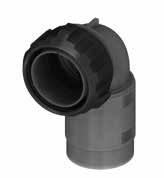
Grounding finger for Shell 98/981
“L” can be different from the value indicated according to backshells accessories, wires size and some special insert configurations.
P/N Sample: KVBS 08STGGT 24-10SX M20 LC F7 N KVBS 08 ST
Series Code Shell Type Connector Class Shell finish
Grommet (ST - ST1 - ST2 Class only)
Grommet cone (ST - ST1 - ST2 Class only)
Backshell internal thread
Adapter (AST1 - ST1 - AST2 -ST2 Class only)
(#) In some sizes the grommet cone is not needed Metal Adapter
Insulating material - Thermoplastic resin
KVBS Series Code KVBS Bayonet Connector with protected mating ramps
Shell Material - Aluminum
08 Plug Connector with 90° elbow without grounding finger
98 Plug Connector with 90° elbow with grounding finger
08 Shell Type
ST Connector Class
81 Plug Connector with 90° elbow without grounding finger Rubber covered coupling nut (short version)
981 Plug Connector with 90° elbow Rubber covered coupling nut (short version) with grounding finger
AST with waterproof O-ring (IP67***)
ST with waterproof O-ring and grommet (IP67***)
AST1 with waterproof O-ring (IP67***)
ST1 with waterproof O-ring and grommet (IP67***)
AST2 with waterproof O-ring (IP67***)
ST2 with waterproof O-ring and grommet (IP67***)
*** Protection degree: IP 67 (only in the mating area with mated connectors) according to EN 60529
T Connector Modification** T With plastic caps
GG Coupling Nut Type GG Rubber Covered
24-10 Insert Arrangement Page 14
S Contact Gender S Socket contacts P Pin contacts
X Polarization Code** Page 14
M20 Backshell internal thread Mxx Provided with an internal Metric thread
LC Contact Termination LC Less contacts
Contact Plating - Silver plating
F7 Shell finish
CD5 Gold plating
F7 Black epoxy varnish (*)
F16 CCF - Black passivation (*) conductive
F26 hard anodization (*)
N Modification Code** N Consult our sales office S
(*) RoHS compliance (**) If required
Plug Connector with rubber covered coupling nut (08..GG - 81..GG - 98..GG - 981..GG) with 90° Elbow Class (AST..FS - ST..FS)
Connector with backshell with internal cable retention system (on request ST1/ST2 with clamps for cable diameter reduction) with a special adapter for UNI4883 rubber conduits. Rubber covered coupling nut able to protect against dust and impact.
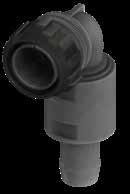
Grounding finger for Shell 98/981
Please consult our Sales Office for further details about this
and according to conduit size.
Series Code Shell Type Connector Class Shell finish
Grommet (ST - ST1 - ST2 Class only)
Backshell Conduits size
Adapter (AST1 - ST1 - AST2 -ST2 Class only)
Grommet cone (ST - ST1 - ST2 Class only)
Insulating material - Thermoplastic resin
KVBS Series Code KVBS Bayonet Connector with protected mating ramps
Shell Material - Aluminum 08 Shell Type
08 Plug Connector with 90° elbow without grounding finger
98 Plug Connector with 90° elbow with grounding finger
81 Plug Connector with 90° elbow without grounding finger Rubber covered coupling nut (short version)
981 Plug Connector with 90° elbow Rubber covered coupling nut (short version) with grounding finger
AST with waterproof O-ring (IP67***)
ST with waterproof O-ring and grommet (IP67***)
AST1 with waterproof O-ring (IP67***)
ST Connector Class
ST1 with waterproof O-ring and grommet (IP67***)
AST2 with waterproof O-ring (IP67***)
ST2 with waterproof O-ring and grommet (IP67***)
(#) In some sizes the grommet cone is not needed
P/N Sample: KVBS 08STGGT 24-10SX FS5040 LC F7 N
24-10 Insert Arrangement
S Contact Gender
X Polarization Code**
T Connector Modification** T With plastic caps GG Coupling Nut Type
Page 14
S Socket contacts P Pin contacts
Page 14
FS Backshell Conduits size FS
Provided with a special adapter for UNI4883 rubber conduits
xxxx Conduit Size xxxx ØA1ØA2
LC Contact Termination
LC Less contactsContact Plating - Silver plating
F7 Shell finish
CD5 Gold plating
F7 Black epoxy varnish (*)
F16
CCF - Black passivation (*) conductive
F26 hard anodization (*)
N Modification Code** N
Consult our sales office S
*** Protection degree: IP 67 (only in the mating area with mated connectors) according to EN 60529
(*) RoHS compliance (**) If required
Connector with backshell provided with an internal Metric thread suitable for cable glands or conduit adapters.
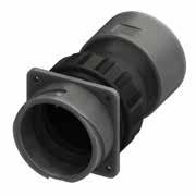
KVBSG - Bayonet Connector with external insulated coating Rear Mounting Receptacle (030) with Backshell Class (DA...M - RA...M) Dimension “L” can be
* For installation with backshell mounted, consult our sales office.
** For use with no rubber covered nut For use with shell type GG coupling nut rubber covered (or shell type 61 or 81), please consult our sales office. *** On request (please consult our Sales Office)
from the value indicated according to backshells accessories, wires size and some special insert configurations.
Series Code Shell Type Connector Class Shell finish
Backshell internal thread
Grommet cone (RA Class only) Grommet (RA Class only)
Backshell
Gasket Isulated Adapter Gasket
The accessories for this class are not always available in stock for all sizes; we suggest you consult our Sales Office for availability
Insulating material - Thermoplastic resin
KVBSG Series Code KVBSG Bayonet Connector with external insulated coating
Shell Material - Aluminum
030 Shell Type 030 Rear mounting Receptacle
DA Connector Class DA with waterproof O-ring (IP67***) RA with waterproof O-ring and grommet (IP67***)
T Connector Modification** T With plastic capsReceptacle connector with threaded holes FP Receptacle connector with through holes
24-10 Insert Arrangement Page 14
LC Contact Termination LC Less contactsContact Plating - Silver plating
CD5 Gold plating
F7 Shell finish
F16
F7 Black epoxy varnish (*)
CCF - Black passivation (*) - conductive
F26 hard anodization (*)
S Contact Gender S Socket contacts P Pin contacts X Polarization Code** Page 14 M20 Backshell internal thread Mxx Provided with an internal Metric thread
G Panel Gasket - Without gasket G With waterproof panel gasket
G3 With waterproof shielded panel gasket N Modification Code** N Consult our sales office S
RoHS compliance (**) If required *** Protection degree: IP 67 (only in the mating area with mated connectors) according to EN 60529
KVBSG - Bayonet Connector with external insulated coating Rear Mounting Receptacle (030) with Backshell Class (DA...FS - RA...FS)
Connector with special adapter for UNI4883 rubber conduits. Conduit’s size must be specified adding the diameter dimensions in the P/N (i.e.: KVBSG 030DA…FS5040…). Rubber covered coupling nut able to protect against dust and impact.
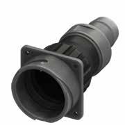
Panel cut out
* For installation with backshell mounted, consult our sales office.
Dimension “L” can be different from the value indicated according to backshells accessories, wires size and some special insert configurations.
for data sheets & assembly instructions.
Series Code Shell Type Connector Class
Backshell Conduits size
(RA..FS Class only)
Grommet cone (RA..FS Class only)
The accessories for this class are not always available in stock for all sizes; we suggest you consult our Sales Office for availability
Insulating material - Thermoplastic resin
KVBSG Series Code KVBSG Bayonet Connector with external insulated coating
Shell Material - Aluminum
030 Shell Type 030 Rear mounting Receptacle
DA Connector Class DA with waterproof O-ring (IP67***) RA with waterproof O-ring and grommet (IP67***)
T Connector Modification** T With plastic capsReceptacle connector with threaded holes FP Receptacle connector with through holes
24-10 Insert Arrangement Page 14
S Contact Gender S Socket contacts P Pin contacts X Polarization Code** Page 14 FS.. Backshell Conduits size
Provided with a special adapter for UNI4883 rubber conduits
LC Contact Termination
Less contactsContact Plating - Silver plating
CD5 Gold plating
F7 Black epoxy varnish (*)
F7 Shell finish
F16
CCF - Black passivation (*) - conductive
F26 hard anodization (*)
G Panel Gasket - Without gasket G With waterproof panel gasket
G3 With waterproof shielded panel gasket
N Modification Code** N
Consult our sales office S
RoHS compliance (**) If required *** Protection degree: IP 67 (only in the mating area with mated connectors) according to EN 60529
Plug Connector (06 - 61 - 96 - 961) with Backshell Class (DA..M - RA..M)
Connector with backshell provided with an internal Metric thread suitable for cable glands or conduit adapters. Rubber covered coupling nut able to protect against dust and impact. KVBSG - Bayonet Connector with external insulated coating
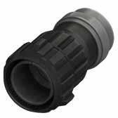
Grounding finger for Shell 96/961
On request (please consult our Sales Office)
Grommet (RA..M RA..PG Class only)
Grommet cone (RA..M RA..PG Class only)
Gasket The accessories for this class are not always available in stock for all sizes; we suggest you consult our Sales Office for availability Isulated
Backshell internal thread Insulating material - Thermoplastic resin
Connector with external insulated coating
Contact
Connector with grounding finger
Plug Connector without grounding finger
covered coupling nut (short version)
Connector
covered coupling nut (short version) with grounding finger
with waterproof O-ring (IP67***)
with waterproof O-ring and grommet (IP67***)
Connector Modification** T With plastic caps
Backshell internal thread
Contact Termination
Contact Plating
with an internal Metric thread
Silver plating
Gold plating
Black epoxy varnish (*)
- Black passivation (*) - conductive
hard anodization (*)
Modification Code**
KVBSG - Bayonet Connector with external insulated coating
Plug Connector (06 - 61 - 96 - 961) with Backshell Class (DA..FS - RA..FS)
Connector with special adapter for UNI4883 rubber conduits.
Conduit’s size must be specified adding the diameter dimensions in the P/N (i.e.: KVBSG 06DA…FS5040…).
Rubber covered coupling nut able to protect against dust and impact.
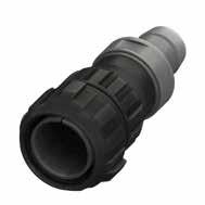
Grounding finger for Shell 96/961
Rubber Conduit not included
Please consult our Sales Office for further details about this dimension and according to conduit size.
Series Code Shell Type Connector Class
Backshell Conduits size Shell finish
(RA..FS Class only)
The accessories for this class are not always available in stock for all sizes; we suggest you consult our Sales Office for availability
Insulating material - Thermoplastic resin
KVBSG Series Code KVBSG Bayonet Connector with external insulated coating Shell Material - Aluminum 06 Shell Type 06 Plug Connector without grounding finger 96 Plug Connector with grounding finger 61 Plug Connector without grounding finger Rubber covered coupling nut (short version) 961 Plug Connector Rubber covered coupling nut (short version) with grounding finger
DA Connector Class DA with waterproof O-ring (IP67***) RA with waterproof O-ring and grommet (IP67***) #
T Connector Modification** T With plastic caps
P/N Sample: KVBSG 06DAT 24-10SX FS2015 LC F7 N
24-10 Insert Arrangement Page 14
S Contact Gender S Socket contacts P Pin contacts X Polarization Code** Page 14 FS Backshell Conduits size
Provided with a special adapter for UNI4883 rubber conduits
Size
LC Contact Termination LC Less contactsContact Plating - Silver plating
F7 Shell finish
CD5 Gold plating
F7 Black epoxy varnish (*)
F16 CCF - Black passivation (*) conductive
F26 hard anodization (*)
N Modification Code** N
Consult our sales office S
KVBSG - Bayonet Connector with external insulated coating
Plug Connector (08 - 81 - 98 - 981) with 90° Elbow Class (DA..M - RA..M) Dimension “L”
Connector with backshell provided with an internal Metric thread suitable for cable glands or conduit adapters. Rubber covered coupling nut able to protect against dust and impact.
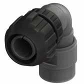
Grounding finger for Shell 98/981
On request (please consult our Sales Office)
Grommet cone (RA..M RA..PG Class only) # Grommet (RA..M RA..PG Class only)
Insulating material - Thermoplastic resin
KVBSG Series Code KVBSG Bayonet Connector with external insulated coating
Shell Material - Aluminum
08 Shell Type 08 Plug Connector with 90° elbow without grounding finger
98 Plug Connector with 90° elbow with grounding finger
81 Plug Connector with 90° elbow without grounding finger Rubber covered coupling nut (short version)
981 Plug Connector with 90° elbow Rubber covered coupling nut (short version) with grounding finger
DA Connector Class DA with waterproof O-ring (IP67***) RA with waterproof O-ring and grommet (IP67***)
T Connector Modification** T With plastic caps
P/N Sample: KVBSG 08DAT 24-10SX M20 LC F7 N KVBSG 08 DA 24-10 S X
*** Protection degree: IP 67 (only in the mating area with mated connectors) according to EN 60529 M20
Backshell internal thread
The accessories for this class are not always available in stock for all sizes; we suggest you consult our Sales Office for availability
24-10 Insert Arrangement Page 14
S Contact Gender S Socket contacts P Pin contacts X Polarization Code** Page 14 M20 Backshell internal thread Mxx Provided with an internal Metric thread
LC Contact Termination LC Less contacts
Contact Plating - Silver plating
F7 Shell finish
CD5 Gold plating
F7 Black epoxy varnish (*)
F16
CCF - Black passivation (*) - conductive
F26 hard anodization (*)
N Modification Code** N
Consult our sales office S
(*) RoHS compliance (**) If required
(#) In some sizes the grommet cone is not needed
Plug Connector (08 - 81 - 98 - 981) with 90° Elbow Class (DA..FS - RA..FS)
Connector with special adapter for UNI4883 rubber conduits. Conduit’s size must be specified adding the diameter dimensions in the P/N (i.e.: KVBSG 08DA…FS5040…).
Rubber covered coupling nut able to protect against dust and impact.
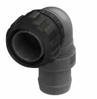
Grounding finger for Shell 98/981
Dimension “L” can be different from the value indicated according to backshells accessories, wires size and some special insert configurations.
KVBSG - Bayonet Connector with external insulated coating
KVBSG 08 DA 24-10 S X
Series Code Shell Type Connector Class
Grommet cone (RA..FS Class only) #
xxxx
Backshell Conduits size Shell finish
Grommet (RA..FS Class only)
Insulating material - Thermoplastic resin
KVBSG Series Code KVBSG Bayonet Connector with external insulated coating
Shell Material - Aluminum 08 Shell Type 08 Plug Connector with 90° elbow without grounding finger
98 Plug Connector with 90° elbow with grounding finger 81 Plug Connector with 90° elbow without grounding finger Rubber covered coupling nut (short version) 981 Plug Connector with 90° elbow Rubber covered coupling nut (short version) with grounding finger
DA Connector Class DA with waterproof O-ring (IP67***) RA with waterproof O-ring and grommet (IP67***) #
T Connector Modification** T With plastic caps 24-10 Insert Arrangement Page 14 S Contact Gender S Socket contacts P Pin contacts X Polarization Code** Page 14 FS Backshell Conduits size FS
Provided with a special adapter for UNI4883 rubber conduits xxxx Conduit Size xxxx ØA1ØA2
LC Contact Termination LC Less contactsContact Plating - Silver plating
F7 Shell finish
CD5 Gold plating
F7 Black epoxy varnish (*)
F16 CCF - Black passivation (*) conductive
F26 hard anodization (*) N Modification Code** N Consult our sales office S
RoHS compliance (**) If required *** Protection degree: IP 67 (only in the mating area with mated connectors) according to EN 60529
P/N Sample: KVBSG 08DAT 24-10SX FS2015 LC F7 N
The accessories for this class are not always available in stock for all sizes; we suggest you consult our Sales Office for availability (#) In some sizes the grommet cone is not needed 90° Elbow
The rear mounting panel connectors can be also supplied with different mounting holes. Please refer to the dimensional tables below. Dimensions
* M5 front mounting panel, M4 Real mounting panel Shell size
Accessories For Connectors
Caps with chain for connectors version: shell type with ramp Provided with sealing gasket. Chain and lugs are in stainless steel. Protection degree: IP 67 (mated to the connector) according to EN 60529.
Finishes : F7 Black epoxy varnish (RoHS compliance)
Finishes : F16 CCF - Black passivation (RoHS compliance) - conductive
Caps with chain for connector version: shell type with coupling nut These caps have no sealing gasket because mated with connectors generally provided with front gasket. Chain and lugs are in stainless steel. Protection degree: IP 67 (mated to the connector) according to EN 60529.
These caps are used to protect connectors against dust. They are not included in the connectors and have to be ordered separately.
The drawings are indicative only and they could be change according to the size
Caps for connectors version: shell type with ramp
Caps for connector version: shell type with coupling nut
Caps for connector version: shell type with rubber covered coupling nut
042-18
042-20
042-22
042-24
PCVBSG 042-28
PCVBSG 042-36
PCVBSG 042-40
** On request (please consult our Sales Office)
These cable-clamps keep the cable in the connector axial position and guarantee an excellent mechanical strain relief. MS 3420 or RF 3420 Bushing are not waterproof and are generally supplied separately except for classes AF,F,LAF and LF connectors.
Finishes : F7 Black epoxy varnish (RoHS compliance)
Finishes : F16 CCF - Black passivation (RoHS compliance) - conductive
MS 3420 - … - RF 3420 - … Bushing
They are made of elastomeric rubber and used with cable Clamp MS3057 - ...A to protect the cable.
In the same cable-clamp it is possible to assemble more than one bushing (inside each other) so to achieve diameters much smaller than the nominal.
Available in two versions:
• MS 3420 - … in neoprene rubber.
• RF 3420 - … in flame resistant rubber.
MS 3057 - ...C - RF 3057 - ...C water tight Cable Clamp
Besides guaranteeing an excellent mechanical strain relief keeping the cable in the centre of the connector, these cable-clamps are provided with an internal conical rubber bushing ensuring waterproof protection. The screws in stainless steel have elastic rose-cut antivibration head.
Available in two versions:
• MS 3057 - …C with gasket in neoprene rubber.
Finishes : F7 Black epoxy varnish (RoHS compliance)
20 - 22
24 - 28
F7
F7
F7
36 VS705258 MS 3057-24C F7
F7
Finishes : F16 CCF - Black passivation (RoHS compliance) - conductive
- 22
- 28
• RF 3057 - …C with gasket in flame resistant rubber. Gasket on request: V = Fluoride Rubber - S = Silicone Rubber
F16
F16
F16
F16
F7
F7
F7
F7
F16
F16
F16
Accessories For Connectors
MS 3420 - ...A - RF 3420 - ...A Bushing
They are made of elastomeric rubber and used with cable clamp MS 3057 - ...C to protect the cable. They allow using cables with diameter smaller than the nominal.
Available in two versions:
• MS 3420 - …A in neoprene rubber.
• RF 3420 - …A in flame resistant rubber (on request).
Accessories For Connectors
These gaskets are used to make panel connectors water resistant.
Gaskets for rear mounting panel connectors (03 - 030 - 038 connectors)
Gasket C216: non conductive chloroprene rubber gasket (IP67 protection)
Gaskets C216G3: conductive silicone gaskets with embedded metal screen. These gaskets guarantee watertightness and RFI shielding
• Elastomer binder: Silicone
• Conductive filler: Nickel Graphite
• Color: Gray
• Operating Temperature range: -60 °C ÷ +220 °C
• Flammability Rating: UL 94-V0
• Salt spray test > 96 h ( consult our sales office for details)
• IP67 protection (EN 60529)
Part Number
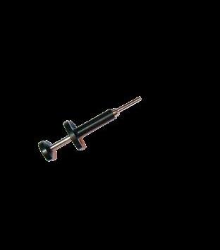
VS610016
VS610042
VS610041
VS610040
VS610043
VS610056
For the instructions concerning assembly and crimping of contacts please consult the appropriate manuals.
We recommend to respect the following general rules:
• always use the tools recommended by Van-System’s catalogue or manuals
• apply the suggested norms for tool maintenance and calibration
• always use tool to close retention spring when crimping the contacts size 12
DO NOT USE ALTERNATIVE GREASES OR OILS which could damage the insert and affect the functionality of the connector.
Short Description
Crimping Die
LOC-KVBS-784 Locator
KTES-784-8
KTES-784-12
KTES-784-16
KTRS-784-12
CDI-VS61138
Removal Tool
Removal Tool
Removal Tool
Tool To Close Retention Spring
Locator for contacts KT 8-38
To use the connectors described in this catalogue according to the necessary safety requirements we suggest you apply the following criteria:
• use the connectors and connected cables within their electrical and environmental limits
• follow the characteristics of each version (shell, class and type of strain relief) and carefully choose the appropriate connector for the required use
• make sure to respect the procedures regarding the correct assembly of connectors and the crimping of contacts
• any connector damaged during shipment, storage, assembly or use should be replaced
• never uncouple the connectors when under power
• always protect the parts against shock when the circuit is under power
• always check the circuit before putting it under power
• consult Radiall Italia Srl if in doubt
• the user must take final responsibility for electrical safety Radiall Italia Srl reserves the right to amend the specifications of this catalogue without issuing prior notice.
For the instructions concerning assembly and crimping of contacts please consult the appropriate tools manuals.
We recommend to respect the following general rules:
• to be used always the tools recommended by Radiall Italia Srl’s catalogue or manuals
• to be applied the suggested norms for tool maintenance and calibration
DO NOT USE ALTERNATIVE GREASES OR OILS which could damage the insert and affect the functionality of the connector. Radiall Italia Srl reserves the right to amend the specifications of this catalogue without issuing prior notice.
The data defined in this document are given as an indication. In the effort to improve our products, we reserve the right to make any change judged necessary.
www.radiall.com FRANCE RADIALL S.A. Tel +33149353535 info@radiall.com 2022 EDITION 06.2022
www.vansystem.eu