
CIRCULAR CONNECTORS CVBS - CVBR - CVBSG - GVJ
For Railway applications
GENERAL CATALOG
About Us
Since 1952, Radiall Sa have been enabling the future through collaboration with our customers. The results are a range of innovative and award-winning products that customers trust for unrivaled repeatability and performance.
Radiall Sa are a global company with facilities around the world that specializes in manufacturing the highest quality interconnect components to support the most demanding applications.
At Radiall, you can rely on us to be the industry’s global market leader.
VanSystem was a company founded in Lombardy - Italy, which has been operating since 1985 in the industrial market. Since 2015 VanSystem is a Radiall company.
Besides connectors with screw or bayonet coupling complying with the Mil-DTL-5015 standard, we designs and manufactures non-standard products for special applications.
One of our’s strong points is an agile and dynamic organizational structure which enables direct and constant interaction with customers in order to meet all their requirements and build solid, long-term partnerships. Our team’s professionalism, skill and commitment are at your service to help you achieve the solution you are looking for.
Radiall Italia S.r.l. Quality System is qualified according to ISO 9001:2015 and ISO/TS 22163:2017
2 Go online for data sheets & assembly instructions. Visit www.radiall.com/vansystem and enter the part number.
Product Selection Guide - Index
Find your connector in 4 steps!
Connector Components
What do you need? Make your choice
What is your Application? Define the insulating material.

INSERTS
CONTACTS
What are the electrical characteristics? Choose the Arrangement
you need internal electrical insulation?
you need an alternative Insert Position?
What contact do you need? Check the wire section/AWG
What is your application? Define the contact type.
What is your Application? Define the Shell.
SHELLS
Do you need CVBS Bayonet Connectors?
or Thermoplastic type
or GVJ Oversize Bayonet Connectors?
ACCESSORIES and CRIMP TOOLS Do you need accessories or crimp tools?
Contacts
with connectors
or Special Contacts
Receptacle Connectors (Shell Type 01)
Nut Receptacles (Shell Type 07 070)
(Shell Type 06 08)
Grounding Finger Connectors (Shell Type 96 98)
Connector (Shell Type TB)
Connectors (Shell Type 00 020 02)
Connectors (Shell Type 06 08)
3 Go online for data sheets & assembly instructions. Visit www.radiall.com/vansystem and enter the part number.
1 2 3 3
Let’s go to page n°...
Rubber
Page 18
Number of contacts Page 24 Insert size Page 50 Voltage (Service Rating) Page 50 Current Rating Page 50
Grommet Page 50 Do
Polarization Code Page 60
Do
Standard
Page 22 Standard
Page 347
supplied
supplied separately
Contact Plating Page 347 Crimp Adapters Page 362 Coaxial Contact Page 363 Thermocouple Contact Page 364
Shell
Page 17 Shell type
Page 66
finishes
- Connector Class
Receptacle
Page 70 In-Line
Page 128 Jam
EMI
Page 200/228
Page 268
Page 270
Page 318 Plug
Page 332
Metal
Page 370 Plastic
Page 374 Panel
Page 376 Cable gland Page 378 Contact hole
Page 384 Crimp
Page 385 Part number explanation Pages 4-7 Detailed Index Page 396
Connectors (Shell Type 00 020 02 030 03)
Page 162 Plug Connectors
Page 166
Through-Bulkhead
Dummy Receptacle Connectors (Shell Type 05)
Receptacle
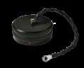
Caps
caps
Gaskets
plugs
Tools
Part number explanation

4 Go online for data sheets & assembly instructions. Visit www.radiall.com/vansystem and enter the part number.
Flange
Coupling Nut Connector class Accessories for connectors
Insulating inserts Contacts
Plug Shells
Grommet Backshell
Compression Ring Cable Clamp
Part number explanation
RF Insulating material
CVS Series Code
- Chloroprene rubber
V Fluoride rubber (Aggressive environments)
S Silicone rubber (-55°C ÷ 200°C)
RF Fire resistant rubber (EN45545 R22- R23 / HL3)
CVS Threaded Connector
CVB Bayonet Connector
CVBS Bayonet Connector with protected mating ramps
CVBSG Bayonet Connector with external insulated coating
CVBR Bayonet Connector roller studs - for harsh applications
GVJ Oversize Bayonet Connector
303 Shell Material - Aluminum
303 Stainless Steel 303 (CVS - CVB)
316 Stainless Steel 316L (CVB)
00 Shell Type xx Flange/Plug Shell with ramp/threaded or with nut
DA Connector Class xx With backshell /Cable clamp
T With plastic caps
FF Receptacle connector with threaded holes (to specify for 00/02/05 shell only)
T Connector Modification**
FP Receptacle connector with through holes (to specify for 03 shell only)
FS Receptacle connector with countersunk holes
GG Rubber covered nut (CVBS and CVBR version only)
V Insert and contacts sealed (solder only)
20-27 Insert Arrangement xx-xx Size - Arrangement
S Contact Gender
S Socket contacts P Pin contacts
X Polarization Code** - No rotation W,X,Y,Z,Q Rotation
PG16 Backshell Conduits size or internal thread - Without internal thread xx Conduits size or internal thread
- Solder contacts
CR Crimp contacts
LC Less contacts
CR Contact Termination
DS PCB contacts
CLT* Longer contacts for grounding solder termination (CLT CR with crimp contacts)
LT* Grounding contact connected to the shell (LT CR with crimp contacts)
CD5 Contact Plating - Silver plating
F7 Shell finishes
CD5 Gold plating
CD15 Gold plating heavy
F4
CCF - Green passivation - conductive
F5 Electroless nickel (RoHS compliance)
F7 Black epoxy varnish (RoHS compliance)
F12 Black Hard Deep Anodization - not conductive (RoHS compliance)
F16 CCF - Black passivation - conductive (RoHS compliance)
F26 Black Hard Anodization (RoHS compliance)
F30 colorless passivation for stainless steel (RoHS compliance)
G Panel Gasket - Without gasket
G With waterproof panel gasket
G2 With shielded panel gasket
G3 With waterproof shielded panel gasket
Nxx Contacts and hole plugs (Consult our sales office)
N101 Modification Code**
Sxx
Customization (Consult our sales office)
** If required * Consult our sales office
5 Go online for data sheets &
instructions. Visit www.radiall.com/vansystem and enter the part number. RF CVS 00 DA 20-27 S X PG16 CR CD5 F7 G N101 P/N
RF
303 00DAT 20-27SX PG16 CR CD5 F7 G N101
assembly
Sample:
CVS
303
T
Part number explanation - Shell type
FF FP FS Flange - Shell Type with ramp or threaded
Shell 00 Front mounting receptacle connector able to accept rear accessories (ordered with accessories)
Shell 020 Front mounting receptacle connector able to accept rear accessories (ordered without accessories)
Shell 02 Front mounting receptacle connector unable to accept rear accessories (standard version)
Shell 02A Front mounting receptacle connector non enviromental (equivalent MS3102A threaded version or MS3102A..B bayonet version)
Shell 02R Front mounting receptacle connector enviromental seal (unable to accept rear accessories)
Shell 03 Rear mounting receptacle connector unable to accept rear accessories
Shell 03A Rear mounting receptacle connector non enviromental (equivalent MS3103A threaded version or MS3103A..B bayonet version)
Shell 03R Rear mounting receptacle connector enviromental seal (unable to accept rear accessories)
Shell 030 Rear mounting receptacle connector with thread to accept backshells
Shell 038 Rear mounting receptacle connector with thread to accept backshells, with 90° elbow
- - - Shell 07 Rear mounting Jam Nut receptacle connector unable to accept rear accessories. Mounting is made by a front fixing-nut
- - - Shell 07R Rear mounting Jam Nut receptacle connector enviromental seal, unable to accept rear accessories. Mounting is made by a front fixing-nut
- - - Shell 070 Rear mounting Jam Nut receptacle connector with thread to accept backshells. Mounting is made by a hexagonal fixing-nut
- - - Shell 078 Rear mounting Jam Nut receptacle connector with thread to accept back shells with 90° elbow. Mounting is made by a hexagonal fixing-nut
- - - Shell 01 In-line receptacle able to accept rear accessories.
Shell TB Through-Bulkhead connector
Shell 05 Dummy receptacle connector
1 GG Plug - Shell Type with coupling nut
Shell 06 Plug connector, for straight backshell
Shell 61 Plug connector, for straight backshell, coupling nut rubber covered (short version)
Shell 96 Plug connector, provided with grounding finger - with straight backshell
Shell 08 Plug connector, with 90° elbow
Shell 81 Plug connector, with 90° elbow, coupling nut rubber covered (short version)
Shell 98 Plug connector, with 90° elbow, with grounding finger
Shell 26 Front mounting receptacle connector
Shell 65 Plug connector, for straight backshell with heavy duty coupling nut
Shell 965 Plug connector, provided with grounding finger - with straight backshell and heavy duty coupling nut
Shell 265 Front mounting receptacle connector with heavy duty coupling nut
Shell 961 Plug connector, provided with grounding finger - with straight backshell, coupling nut rubber covered (short version)
Shell 981 Plug connector, provided with grounding finger - with 90° elbow, coupling nut rubber covered (short version)
6 Go online for data sheets & assembly instructions. Visit www.radiall.com/vansystem and enter the part number.
grounding finger 1 = rubber
GG = could be supplied
rubber
coupling
Avalaible 9
= with
covered coupling nut, short version
with
covered
nut
9
Flange Plug
00
Standard version On request FF = threaded holes FP = through holes FS = countersunk holes
Connector class - Backshell
Part number explanation - Connector Class - backshell
Without O-ring and Grommet (non-watertight)
With waterproof O-ring
With waterproof O-ring and Grommet
1 2 3
- A DA RA
- - LA LDA LRA
Connector Class - backshell
Backshell having an external thread suitable for MS3057…A or C type cable-clamps
Long backshell having an external thread suitable for MS3057…A or C type cable-clamps
- - AF F With backshell, MS 3057...A type cable-clamps and bushing MS 3420 (for single wire)
- - LAF LF With long backshell, MS 3057...A type cable-clamps and bushing MS 3420 (for single wire)
- AC ACF With backshell and MS 3057...C type cable-clamps (for jacketed cable)
- - ACB ACFB With backshell, MS 3057...C type cable-clamps and bushing MS 3420A (for jacketed cable)
- - LAC LACF With long backshell and MS 3057...C type cable-clamps (for jacketed cable)
- - AB ABF With backshell and MS 3057...B type cable-clamps (for jacketed cable)
- - AS ASF With backshell and MS 3057...A type cable-clamps (for single wire)
DA..PG RA..PG With an internal PG thread
DA..M RA..M With an internal Metric thread
- DA..PH RA..PH With a PG thread metal cable glands
- DA..MH RA..MH With a Metric thread metal cable glands
- DA..FS RA..FS With a special adapter for UNI4883 rubber conduits
- DA..MTG RA..MTG With a special adapter for UNI4883 rubber conduits, with nut
- - - - - DAM RAM
- - AR R
- - AG G
- - AG2 G2
- - ASB1 SB1
With rubber coated backshell and strain relief (CVBSG series only)
Suitable to connect single wires (when strain relief is not necessary)
Suitable for heat shrink tubing applications
Suitable for heat shrink tubing applications, with nut
Backshell for multicore jacketed shielded cables, provided with MS 3057…C type cableclamps (for jacketed cable)
- - AGV GV With backshell for shield hose and heat shrink tubing termination
- - SB With backshell for shield hose and heat shrink tubing termination, with nut
- AMK MK
- AWN WN
- - FA FM
- - P
- - AST ST
- - AST..M ST..M
- - AST..FS ST..FS
With gasket and an iris spring connected to one another by an internal ring. The iris spring is used to connect multicore jacketed cables or jacketed hoses
With gasket and an iris spring connected to one another, to guarantee an excellent mechanical strain relief and water tightness
With backshell, MS 3057...A type cable-clamps and front gasket (for single wire)
Backshell for potting
Backshell with internal cable retention system (on request ST1/ST2 with clamps for cable diameter reduction) with an external unef thread
Backshell with internal cable retention system (on request ST1/ST2 with clamps for cable diameter reduction) with an internal Metric thread
Backshell with internal cable retention system (on request ST1/ST2 with clamps for cable diameter reduction) with a special adapter for UNI4883 rubber conduits
- - - DA..PHM RA..PHM With quick-assembly strain relief.
- - - DA..PHM..E RA..PHM..E With quick-assembly strain relief and device for connecting a shielded braid to connector shell.
7 Go online for data sheets & assembly instructions. Visit www.radiall.com/vansystem and enter the part number. CVS CVB CVBS CVBSG CVBR GVJ
Avalaible DA On request 1 3 2
General Characteristics
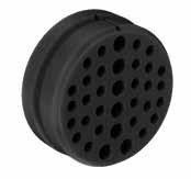
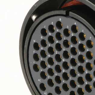
INSERTS
VanSystem is able to offer connectors with insulators suitable for low or high voltage with layout from 1 to 201 contacts.
They are manufactured with the following compound:
• Chloroprene rubber
• Fluoride rubber
• Silicone rubber
• Fire resistant rubber
• Thermoplastic
The inserts could be supplied with materials in accordance with EN 45545-2 specification.
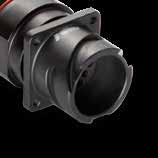
SHELLS
Available in several versions suitable for all applications and manufactured in different materials and finishes:
• Aluminum alloy with different types of protection finishes according to RoHS directives.
• Stainless steel, brass nickel plated and other materials to be chosen according to the application
• Coupling nut threaded or bayonet version
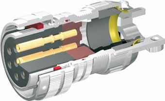
The bayonet connectors are derived from the threaded series to provide faster coupling and anti-vibration resistance.
In the CVB, CVBS and CVBR series the coupling system is composed of 3 bayonet ramps machined on the external side of the receptacle connector and 3 stainless steel studs mounted inside the plug connector’s coupling nut.
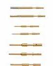
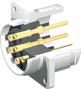
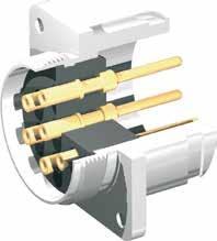
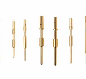
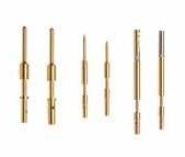
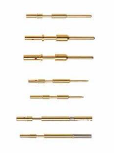
CONTACTS
Available in solder or crimp contacts, terminations for wave soldering or printed circuit board, machined from copper alloys and finished with gold or silver platings.
All contacts are manufactured in order to guarantee optimum connection properties and to provide resistance to vibration and continuous mating and unmating cycles.
Contacts for particular applications, alternative termination types and with special finishes are available to suit specific requirements.
8 Go online for data sheets & assembly instructions. Visit www.radiall.com/vansystem and enter the part number.
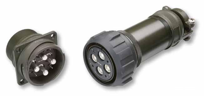
CVS - General Characteristics
THREADED CIRCULAR CONNECTORS
This series is according to Mil-DTL-5015 specification, which concerns the electrical connectors usually called “MS”. These connectors were designed for aviation applications and they has been used for many industrial applications thanks to their versatility, reliability and ease of supply.

MAIN Characteristics:
• Used in industrial applications thanks to their versatility
• 12 different shell sizes with a wide range of back shells and strain relief options for any cable requirement
• Insulating inserts and grommets are manufactured with synthetic, highly insulated, rubber compounds
• Contacts available in crimp, solder and PCB terminal

9 Go online for data sheets & assembly instructions. Visit www.radiall.com/vansystem and enter the part number.
CVB - General Characteristics
BAYONET CIRCULAR CONNECTORS
This is the basic series. The front seal has a double function: it is used to supply the elastic return during the coupling and to guarantee waterproof protection.The locking is obtained by a ramp end drop of 0.15 mm. The series is compatible with all connectors in accordance with VG95234 specification.
Main characteristics:
• Coupling-nut rotation of 120° only to mate connectors
CVB Ramp detail
• Audible, visible and tactile mating
• Interfacial seal between the two halves of the connector
• The bayonet ramps are resistant to damage
Advantages against the threaded version:
• Fast coupling and uncoupling
• The security of coupling is guaranteed and therefore its reliability is improved
• Resistance to loosening of the coupling nut also in vibration or impact condition
• IP67 waterproof protection when connectors are mated
• High number of mating cycles

10 Go online for data sheets & assembly instructions. Visit www.radiall.com/vansystem and enter the part number.
0,15 mm
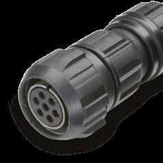
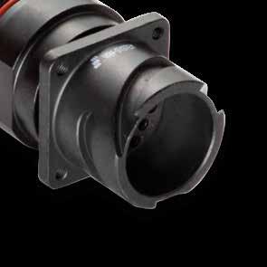
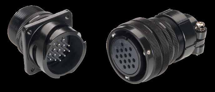
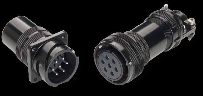
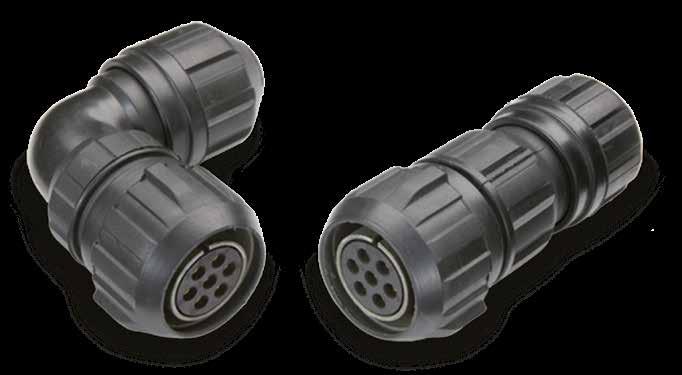
CVBS - General Characteristics
BAYONET CONNECTORS PROTECTED BY A STAINLESS STEEL STUD
This series, deriving from Mil-DTL-5015 and VG95234 specs, has become a popular standard among railway connection applications. Its success is mainly due to the bayonet coupling system composed of three ramps machined on the external side of the receptacle connector and 3 stainless steel studs mounted inside the plug connector’s coupling nut. The coupling point at the end of the ramp is protected by a stainless steel roller able to increase the number of mating cycles.
CVBS Ramp detail
Main characteristics:
• Fast and reliable coupling (coupling-nut rotation of 120° only and mating is audible, visible and tactile)
• Vibration and impact resistance
• Manufactured in several shell versions as panel connectors (with front or rear mounting) or plug connectors (with straight backshell or 90°) and a wide range of insulators (with combination of different size contacts) from 1 to 201 poles
• Accessories for all types of cables and shielding protection hoses are also available
• Crimp contacts are suitable for wires of all sectionsì
Advantages:
• Faster coupling, continuous and reliable service in the harshest use conditions
• Wave washer installed under the plug connector coupling nut
• IP68 waterproof protection (when connectors are mated and harnessed by using the correct accessories)

11 Go online for data sheets & assembly instructions. Visit www.radiall.com/vansystem and enter the part number.
0,4 mm
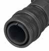
CVBSG - General Characteristics
BAYONET CONNECTORS WITH RUBBER COVERED PLUG SHELL
CVBSG series has been modified to design safety connectors. The shells of plug connectors have been rubber jacketed. Accessories in rubber material or with rubber protection are also available for cable retention.
Main characteristics:
• These connectors are particularly suitable for applications with mechanical shock
• Rubber jacket and insulating parts are in accordance with EN 45545-2 standards
• Standard panel receptacle supplied with countersunk holes for easy mating with rubber jacketed nuts
• Accessories made of rubber material or with rubber protection are also available for cable retention

12 Go online for data sheets & assembly instructions. Visit www.radiall.com/vansystem and enter the part number.
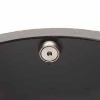
CVBR - General Characteristics
BAYONET CONNECTORS PROTECTED BY A STAINLESS ROLLER STUD
Designed to build a product even more suitable for the harshest application. The studs of the plug connector coupling and a higher number of operations due to a lower wear of the coupling ramps. CVBR series can be supplied from size 18 to size 40.
Main characteristics:
• Suitable for higher number of operations
• The roller-stud guarantees an easier coupling due to a lower wear of the coupling ramps

13 Go online for data sheets & assembly instructions. Visit www.radiall.com/vansystem and enter the part number.
Roller Stud
GG version: with rubber covered coupling nut
GVJ - General Characteristics
OVERSIZE SHELL BAYONET CONNECTOR
This series benefits of the bayonet coupling itself suitable for the harsh conditions typical in railway applications and of more robust and reliable features obtained by the following modifications.
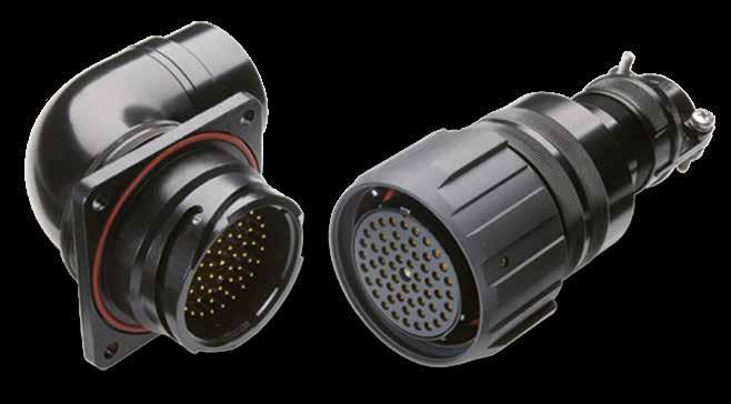
Main characteristics:
• Bigger shell thicknesses to guarantee resistance against impact and harsh environment.
• Rubber-jacketed coupling nut also in the standard series. The roller studs make the coupling easier and allow a bigger number of operations due to a lower wear of the coupling ramps.
• Five key polarization system (a big key and four smaller).
• Increased dimensions to install insulators with bigger number of contacts (on equal service rating) or bigger contact sizes (for higher voltage).
• Wide range of rear accessories and adapters for all types of cables and protections available.

14 Go online for data sheets & assembly instructions. Visit www.radiall.com/vansystem and enter the part number.
Circular Connectors
International Standard Document Compliance
• MIL-DTL-5015: Connectors, Electrical, Circular threaded, an type, general specification for
• SAE AS 39029: Contacts, Electrical Connectors, general specification for
• VG 95234: Electrical connectors with bayonet coupling pressure-water tight, up to 245A
• EN 50124-1: Railway applications - Insulation coordination
• IEC 60077-1: Railway applications - Electric equipment for rolling stock
• EN 45545-2: Railway applications - Fire protection on railway vehicles
• NFPA 130 (ASTM E 162, ASTM E 662): Standard for Fixed Guideway Transit and Passenger Rail Systems
• UNI CEI 11170-3 : Guidelines for railway vehicle protection for tramways and with guided rail
• NFF 16-102: Railway Rolling Stock - Fire Behavior
• EN 50467: Railway applications - Rolling stock - Electrical connectors, requirements and test methods
• IEC 61373: Railway applications. Rolling stock equipment. Shock and vibration tests
• IEC 60529: Degrees of protection provided by enclosures (IP Code)
• European Directive 2011/65: RoHS complying
Features and Benefits
Robust Connection
• Fully protected connectors: no risk to damage the contacts thanks the robust shell
• Supplied with grounding finger, conductive plating and the proper rear accessory
• Suitable for polarizations to prevent un-correct coupling
Easy installation
• Fast and reliable coupling
• Backshell and accessories for fastening cable/conduit fixation
Suitable for harsh environments (adapted for outdoor use)
• Waterproof connection
• Dust proof
• Corrosion resistant
High level of performance
• Working temperature -55°C ÷ 200°C (according to the inserts material)
• EMI protection with grounding finger
• Power connection up to 350A
APPLICATIONS
• Railway
• Energy
• Naval
• Industrial
15 Go online for data sheets & assembly instructions. Visit www.radiall.com/vansystem and enter the part number.
General Characteristics - Shells - Shielding characteristics
Plug connectors with grounding finger (type 96 - 98 - 96GG - 98GG - 965) when mated with receptacle connectors (type 02 - 02000 - 01 - 030 - 038 - 070 - 078) and provided with rear accessories for shielded cables have shielding characteristics according to VG95234 specs.
F16 or F4 Shell Finishes are recommended for electrical conductivity from receptacle to plug.
VG95234 specs: Shielding effectiveness data over frequency range (with conductive shells)
16 Go online for data sheets & assembly instructions. Visit www.radiall.com/vansystem and enter the part number. 0.01 0.1 1 10 100 MHz MHz 20 40 60 70 80 dB 20 40 60 70 80 dB attenuation frequency
Grounding finger
General Characteristics - Shells - Material and Finish
Shells
They are manufactured in aluminum alloy or stainless steel and can be protected against corrosion by the following finishes (Halogen-free):
• F4 : CCF-Green passivation (conductive)
• F5 : Electroless Nickel (conductive) - RoHS (*)
• F7 : Black epoxy varnish (not conductive) - RoHS (*)
• F12 : Black Hard Deep Anodization (not conductive) - RoHS (*)
• F16 : CCF-Black passivation (conductive) - RoHS (*)
• F26 : Black Hard Anodization - RoHS (*)
• F30 : Colorless passivation for stainless steel ( for AISI 303 or AISI 304 - without passivation AISI 316L) - RoHS (*)
(*) Restriction of Hazardous Substances Directives of the European Parliament n°2002/95/EC issued on 27 January 2003 Alternative materials and finishes are available to suit specific requirements.
Surface Treatment Code
Shell-material
Surface finish CCF cadmiun free electroless nickel epoxypolyurethan Hard Deep Anodizing CCF cadmiun free Anodizing Colorless
Type of surface passivated - varnished passivated passivated passivated passivated
Surface colour green grey black black black blackRohs conformity no yes yes yes yes yes yes
Corrosion resistance 500 h *** 48 h 500 h 2000 h 500 h *** 1000 h >2000 h
Operat. Temperature -55°C ÷
Electrical conductivity good good non-conductive non-conductive good non-conductive good
* For use from 125°C to 200°C, consult our Commercial Office
*** 200 h in case of use with components, panel and screws, in stainless steel (galvanic corrosion)
Coupling mechanism
Mating endurance (IEC 61300-2-2)
Shock and vibrations tests (EN 61373)
IP protection degree (EN 60529)
Threaded Connector (CVS serie)
Reverse Bayonet Connector (CVB/CVBS/CVBSG/CVBR/GVJ Series)
500 mating cycles minimum (for use up to 2000 mating cycles, consult our commercial office)
Category 1 body mounted (CVB/CVBS/CVBSG/CVBR/GVJ Series)
Category 2 bogie mounted (CVBS/CVBSG/CVBR/GVJ Series)
IP54, IP67, CVB/CVBS: IP68 (waterproof to 10 meters - 12 hours) when used with adequate backshell or accessories
& assembly instructions.
17 Go online
sheets
Visit www.radiall.com/vansystem and enter the part number.
for data
F4 F5 F7 F12 F16 F26 F30
Aluminium alloy Stainless Steel
+ 125°C -55°C
+ 200°C* -55°C ÷ + 200°C* -55°C ÷ + 125°C -55°C ÷ + 125°C -55°C ÷ + 125°C -55°C ÷ + 200°C*
÷
General Characteristics - Inserts

Insulating inserts and grommets
They are manufactured with the following synthetic, highly insulated, rubber compounds:
• - : Chloroprene rubber - for non heavy applications. Good resistance to ageing, oils and gasoline. Rated temperature: -55° to 125°C.
• V : Fluoride rubber - for high temperature applications. Excellent resistance to ageing, atmospheric agents, hydraulic fluids and oils. Rated temperature: -25° to 205°C.
• S : Silicone rubber - for high and low temperature applications. Excellent resistance to ageing, nuclear radiations and ozone. Rated temperature: -55° to 200°C.
• RF : Fire resistant rubber - halogen free - employed when no flame propagation, low opacity and non smoke toxicity is requested. Rated temperature: -35° to 180°C.
• GVJ : Thermoplastic resin UL94V0, flame retardant according to EN 45545-2.
Material-Code (Halogen-free)
18 Go online for data sheets & assembly instructions. Visit www.radiall.com/vansystem and enter the part number.
- (standard) V S RF/GVJ GVJ
chloroprene fluoride silicone fire resistant thermoplastic Operat. Temperature -55 ÷ +125°C -25 ÷ +200°C -55 ÷ +200°C -55 ÷ +150°C -25 ÷ +125°C Fire protection class UL94 V0 V0 V0 V0 V0 Fire protection class EN45545-2 - - - HL3 / R22 - R23 HL3 / R22 - R23
Material
General Characteristics - Rated Current and Rated Voltage
The values mentioned below are valid for usage at 20°C ambient temperature. Let us remind you that:
• when temperatures rise, the conductivity of the contacts and therefore the value of the applicable current decreases
• at the operating current and 20°C ambient temperature the connection temperature increases anyway
• in consequence to all of the above, the current applicable to a given temperature and a determined contact size must be carefully considered
The material of the insert must be chosen to comply with both room temperature and the one produced by the electrical connection.
If in doubt we suggest you consult our Sales Office.
Rated current with one contact loaded in a contact arrangement.
* Valid for ambient temperature at 20°C.
** Test according to SAE AS39029 with silver plated wire.
*** Valid for ambient temperature at 80°C.
INSULATING CHARACTERISTICS AND RATED VOLTAGE
The values of the following table:
• are valid for usage at sea level.
**** Available contacts with louver.
• refer to a clean environment of application. The pollution due to metallic or other impurities has to be taken into consideration.
• concern contacts with standard termination, solder or crimping, with size suitable for AWG section wires matching the relevant contact size. It is therefore necessary to pay attention when using contacts with crimp termination bigger than the nominal AWG size.
• Minimum Insulating Resistance ≥ 5GΩ.
MIL-DTL-5015
MIL-DTL-5015
* The connectors do not show any sign of breakdown when the voltage indicated in the table is applied for one minute between the two closest contacts and between the shell and the contact closest to the shell.
Caution : When nominal operating voltage exceeds 50V towards earth, the appropriate safety measures have to be adopted as described by CEI 23, IEC 309-1, BS 2618, VDE 0100 specs. The data shown on the above table are applicable only when the above mentioned safety rules are fulfilled.
19 Go online for data sheets &
Visit www.radiall.com/vansystem and enter the part number.
assembly instructions.
Contact size Maximum current* Rated current*** Maximum voltage drop** Test current Max Contact Resistance 20 7.5A 7.5A 55mV 7.5A <12.0mΩ 18 10A 7.5A 55mV 7.5A <12.0mΩ 16 - 16S 22A 13A 49mV 13A <6.0mΩ 12 41A 23A 42mV 23A <3.0mΩ 8**** 73A 46A 26mV 46A <1.0mΩ 4 135A 80A 23mV 80A <0.5mΩ 0**** 245A 150A 21mV 150A <0.3mΩ 4/0**** 350A 225A 21mV 225A <0.2mΩ
Service code Operating Voltage Vdc Operating Voltage Vac RMS* Test Voltage Vac RMS* I (instruments) 250 200 1000 A 700 500 2000 D 1250 900 2800 E 1750 1250 3500 B 2450 1750 4500 C 4200 3000 7000
General Characteristics - Contacts - electrical characteristics
RATED CURRENT
Recommended current according to the temperature.
Rated current with one contact loaded in a contact arrangement.
Electrical design and production parameters of threaded or bayonet coupling connectors are derived from Mil-DTL-5015 and VG 95234 standards. All circular connectors are produced and tested in accordance of VG 95234 standards.
RATED CURRENT CONTACTS WITH LOUVER**
Also available special contacts for high current.
Contact size 0
** Not included in Mil or Sae Specs
Contact
Contact
20 Go online for data sheets & assembly instructions. Visit www.radiall.com/vansystem and enter the part number.
Temperature
(°C)
(A)
Current
Contact size 4
size 8
size 12
size 16 - 16S
size 18-20
size 4/0 0 20 30 40 50 60 70 80 90 100 110 120 130 20 30 40 50 60 70 80 90 100 110 120 130 10 140 150 160 170 180 190 200 210 220 230 240 250 400 260 270 280 290 300 310 320 330 340 350 360 370 380 390
Contact
Contact
Contact
Contact Size Maximum current Rated Current 8L 90A 56A 0L 300A 200A 4/0L 450A 300A
ø D ø D
General Characteristics
Contacts They are machined in high conductivity copper alloy in order to guarantee optimum connection properties and to provide resistance to vibration and continuous mating and unmating cycles.
They are protected by a silver (standard production) or gold finish with varying plating thickness on request.
As for connector codes to be supplied with specific finish contacts please consult the section referring to the P/N explanations.
Contacts for particular applications, alternative termination types and with special finishes are available to suit specific requirements.
Engagement and disengagement force between contacts
** Not included in Mil or Sae Specs
* Test according to SAE AS39029
21 Go online for data sheets & assembly instructions. Visit www.radiall.com/vansystem and enter the part number.
Contact size Engagement *
Max Disengagement
Max 20 1.8 0.19 18 2.4 0.19 16 - 16S 5 0.56 12 7.5 0.83 8 15 1.39 4 20 2.78 0 42.5 4.17 4/0 ** 42.5 4.17
in N.
* in N.
Contacts - Part number explanation
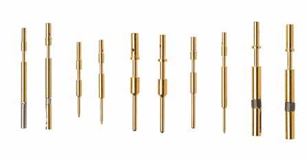
These are available in solder or crimp version.
Solder contacts are normally supplied already installed in the connector.
Crimp contacts instead are supplied loose in a bag inside the connector packing or separately.
Crimp contacts machined from copper alloys and finished with gold or silver platings.
Special power contacts, for signal or shielding are also available. Crimp contacts are commonly used in railways applications.
They can be supplied loose in a bag inside the connector packing or separately.
Contacts material is copper alloy and they are protected by a silver (standard production) or gold finish with varying plating thickness on request.
All contacts are machined in order to guarantee optimum connection properties and to provide resistance to vibration and continuous mating and unmating cycles.
Contacts for particular applications, alternative termination types and with special finishes are available to suit specific requirements.
22 Go online for data sheets & assembly instructions. Visit www.radiall.com/vansystem and enter the part number.
Contact Size Wire section (mm2) AWG cable size 20 0.15÷0.3 26÷22 18 0.15÷0.6 26÷20 16 - 16S 1÷1.5 18÷16 12 3 12 8 - 8 4 22 4 0 53 0 4/0 107÷120 4/0 Standard Crimp Contacts (specify CR in the Part Number) RF CVS 00 DA 20-27 S X PG16 CR CD5 F7 G N 303 T
S Contact Gender S Socket contacts P Pin contacts CR Contact Termination - Solder contacts CR Crimp contacts DS PCB contacts LC Less contacts (To be purchased separately) CD5 Contact Plating - Silver plating CD5 Gold plating N Modification Code N Non standard Contacts and hole plugs (Consult our sales office)
Insulating Inserts And Grommets - Part number explanation
VanSystem is able to offer connectors with insulators suitable for low or high voltage with lay-out from 1 to 201 contacts.
Insulating inserts and grommets are manufactured with synthetic, highly insulated, rubber compounds.
V Fluoride rubber
RF Insulating material - Chloroprene rubber
S Silicone rubber
RF Fire resistant rubber
For non heavy applications. Good resistance to ageing, oils and gasoline.
Rated temperature: -55° to +125°C*
Excellent resistance to ageing, atmospheric agents, hydraulic fluids and oils.
Rated temperature: -25° to +200°C*
For high and low temperature applications. Excellent resistance to ageing, nuclear radiations and ozone.
Rated temperature: -55° to +200°C*
Halogen free
Employed when no flame propagation, low opacity and non smoke toxicity are requested.
Qualified according to:
• EN 45545-2 HL3 R22/R23
• NFPA 130
Rated temperature: -55° to +150°C* 20-27 Size and Insert Arrangement
Size - Arrangement
Inserts and grommets arrangements
List by shell size
List by contacts total quantity X Polarization Code - No rotation W,X,Y,Z,Q Rotation
Alternate insert position
* Temperature range can be changed according to shell finishes.
23 Go online for data sheets &
instructions. Visit www.radiall.com/vansystem and enter the part number. INSERTS
assembly
RF CVS 00 DA 20-27 S X PG16 CR CD5 F7 G N 303 T
xx-xx
1 CONTACT
1 CONTACT
2 CONTACTS
24 Go online for data sheets & assembly instructions. Visit www.radiall.com/vansystem and enter the part number. INSERTS Front view Pin contacts insert Insulating Inserts and Grommets - List by contacts total quantity
Inserts
ST Contacts size legend 20 18 16 12 8 4 0 4/0 20 18 16 12 8 4 0 Grommet Available ** On request (please consult our Sales Office) (L) Long Insert (S) Short Insert (NS) Non Standard Shell Type 4/0
CVS-CVB-CVBS-CVBSG-CVBR -
Arrangement
16-2 1 12 E ** 16-12 1 4 A 18-6 1 4 D 18-16 1 12 C 20-2 1 0 D Insert Arrangement 16-2** 16-12 18-6 18-16** 20-2 N° of Contacts 1 1 1 1 1 Contact Size/ Current rating 12 (23A) 4 (80A) 4 (80A) 12 (23A) 0 (150A) Service Rating E 1750 Vdc 1250 Vac A 700 Vdc 500 Vac D 1250 Vdc 900 Vac C 4200 Vdc 3000 Vac D 1250 Vdc 900 Vac Grommet - - - - -
16 A B A 10SL-4 2 14S-9 2 16 A B A 16S-4 2 16 D B A 16-11 12 A B A 2 18-3 2 12 D B A 18-14 2 1-4, 1-16 A A B Insert Arrangement 10SL-4 14S-9 16S-4 16-11** 18-3 18-14** N° of Contacts 2 2 2 2 2 2 Contact Size/ Current rating 16S (13A) 16S (13A) 16S (13A) 12 (23A) 12 (23A) n° 1- 4 (80A) n° 1-16 (13A) Service Rating A 700 Vdc 500 Vac A 700 Vdc 500 Vac D 1250 Vdc 900 Vac A 700 Vdc 500 Vac D 1250 Vdc 900 Vac A 700 Vdc 500 Vac Grommet - -NEW NEW NEW
22-7 1 0 E Insert Arrangement 22-7** 22A1 (L) 28A1 (L) N° of Contacts 1 1 1 Contact Size/ Current rating 0 (150A) 0 (150A) 4/0 ( 225A) Service Rating E 1750 Vdc 1250 Vac 750V (according to APTA SS-E-001-98) 750V OV4 PD4 Grommet -NEW NEW
CVS-CVB-CVBS-CVBSG-CVBR - Inserts Arrangement
2 CONTACTS
2 CONTACTS
25 Go online for data sheets & assembly instructions. Visit www.radiall.com/vansystem and enter the part number. INSERTS Insulating
contacts total quantity
Front view Pin contacts insert ST Contacts size legend 20 18 16 12 8 4 0 4/0 20 18 16 12 8 4 0 Grommet Available ** On request (please consult our Sales Office) (L) Long Insert (S) Short Insert (NS) Non Standard Shell Type 4/0
Inserts and Grommets - List by
20-23 2 2-8 A A B 22-1 2 2-8 D A B 22-8 2 2-12 E B A 22-11 2 2-16 B B A Insert Arrangement 20-23** 22-1 22-8** 22-11** N° of Contacts 2 2 2 2 Contact Size/ Current rating 8 (46A) 8 (46A) 12 (23A) 16 (13A) Service Rating A 700 Vdc 500 Vac D 1250 Vdc 900 Vac E 1750 Vdc 1250 Vac B 2450 Vdc 1750 Vac Grommet - - -
24-9 2 2-4 A B A 32-5 2 2-0 D B A Insert Arrangement 24-9 32-5 N° of Contacts 2 2 Contact Size/ Current rating 4 (80A) 0 (150A) Service Rating A 700 Vdc 500 Vac D 1250 Vdc 900 Vac Grommet
CONTACTS 3 3-16 A C B A 10SL-3 3 3-16 A C B A 14S-1 14S-7 3-16 A C A B 3 16S-5 3 3-16 C B A ** A 3 1-8, 2-16 AB C A 16-7 3 3-12 C B A A 16-10 Insert Arrangement 10SL-3 14S-1*** 14S-7 16S-5 16-7** 16-10 N° of Contacts 3 3 3 3 3 3 Contact Size/ Current rating 16S (13A) 16S (13A) 16S (13A) 16S (13A) n° 1-8 (46A) n° 2-16 (13A) 12 (23A) Service Rating A 700 Vdc 500 Vac A 700 Vdc 500 Vac A 700 Vdc 500 Vac A 700 Vdc 500 Vac A 700 Vdc 500 Vac A 700 Vdc 500 Vac Grommet -*** Same as
is different from MIL-STD-1651 specs)
3
14S-7S (it
3 CONTACTS
3 CONTACTS
3 CONTACTS
26 Go online for data sheets & assembly instructions. Visit www.radiall.com/vansystem and enter the part number. INSERTS Front view Pin contacts insert Insulating Inserts and Grommets - List by contacts total quantity
Inserts
ST Contacts size legend 20 18 16 12 8 4 0 4/0 20 18 16 12 8 4 0 Grommet Available ** On request (please consult our Sales Office) (L) Long Insert (S) Short Insert (NS) Non Standard Shell Type 4/0
CVS-CVB-CVBS-CVBSG-CVBR -
Arrangement
22-6 2-8, 1-16 A C B D 3 22-9 3-12 A C B 3 E 22-21 1-0, 2-16 B A C 3 A 22A-3 3 3-12 * 1 2 3 C A D E B Insert Arrangement 22-6** 22-9** 22-21 22A3 (L) 24-12/1 N° of Contacts 3 3 3 3 3 Contact Size/ Current rating n° 2-8 (46A) n° 1-16 (13A) 12 (23A) n° 1-0 (150A) n° 2 -16 (13A) 12 (23A) 8 (46A) Service Rating D 1250 Vdc 900 Vac E 1750 Vdc 1250 Vac A 700 Vdc 500 Vac B 2450 Vdc 1750 Vac A 700 Vdc 500 Vac Grommet -
28-3 3-8 A C B 3 E 28-6 3 3-4 D C A B 28A-3 3 3-8 * 3 2 1 Insert Arrangement 28-3 28-6 28A3 (L) N° of Contacts 3 3 3 Contact Size/ Current rating 8 (46A) 4 (80A) 8 (46A) Service Rating E 1750 Vdc 1250 Vac D 1250 Vdc 900 Vac B 2450 Vdc 1750 Vac Grommet NEW NEW
18-5 3 2-12, 1-16 D C B A 18-22 3 3-16 D A B C 20-3 3 3-12 D A B C 20-19 3 3-8 A A B C 3 3-8 D C B A 22-2 Insert Arrangement 18-5 18-22 20-3 20-19 22-2 (NS) N° of Contacts 3 3 3 3 3 Contact Size/ Current rating n° 2-12 (23A) n° 1-16 (13A) 16 (13A) 12 (23A) 8 (46A) 8 (46A) Service Rating D 1250 Vdc 900 Vac D 1250 Vdc 900 Vac D 1250 Vdc 900 Vac A 700 Vdc 500 Vac D 1250 Vdc 900 Vac GrommetNEW
CVS-CVB-CVBS-CVBSG-CVBR - Inserts Arrangement
3 CONTACTS
3 CONTACTS
4 CONTACTS
27 Go online for data sheets & assembly instructions. Visit www.radiall.com/vansystem and enter the part number. INSERTS Insulating Inserts
contacts total quantity
Front view Pin contacts insert ST Contacts size legend 20 18 16 12 8 4 0 4/0 20 18 16 12 8 4 0 Grommet Available ** On request (please consult our Sales Office) (L) Long Insert (S) Short Insert (NS) Non Standard Shell Type 4/0
and Grommets - List by
32A3 3 3-4 * A B C 3 3-0 A:D B/C:A 36-4 C B A Insert Arrangement 32A3 (L) 36-4 N° of Contacts 3 3 Contact Size/ Current rating 4 (80A) 0 (150A) Service Rating E 1750 Vdc 1250 Vac A=D - B/C=A Grommet NEW NEW
14S-2 4 4-16 I C D A B 16-9 4 2-12, 2-16 IA C A D B 18-4 4 4-16 D D C B A 18-10 4 4-12 A C B D A 18-13 4 1-8, 3-12 A C B A D 20-4 4 4-12 D A B C D Insert Arrangement 14S-2 16-9 18-4 18-10 18-13** 20-4 N° of Contacts 4 4 4 4 4 4 Contact Size/ Current rating 16S (13A) n° 2-12 (23A) n° 2- 16 (13A) 16 (13A) 12 (23A) n° 1-8 (46A) n° 3-12 (23A) 12 (23A) Service Rating I 250 Vdc 200 Vac A 700 Vdc 500 Vac D 1250 Vdc 900 Vac A 700 Vdc 500 Vac A 700 Vdc 500 Vac D 1250 Vdc 900 Vac Grommet - -
40A-3 3 3-4 E 3 1 2 40C3 3 3-0 * WV U A B C Insert Arrangement 40A3 (L) 40C3** (L) 40D3 N° of Contacts 3 3 3 Contact Size/ Current rating 4 (80A) 0 (150A) 4/0 ( 225A) Service Rating E 1750 Vdc 1250 Vac B 2450 Vdc 1750 Vac A 700 Vdc 500 Vac Grommet -NEW
4 CONTACTS
4 CONTACTS
5 CONTACTS
28 Go online for data sheets & assembly instructions. Visit www.radiall.com/vansystem and enter the part number. INSERTS Front view Pin contacts insert Insulating Inserts and Grommets - List by contacts total quantity
Inserts
ST Contacts size legend 20 18 16 12 8 4 0 4/0 20 18 16 12 8 4 0 Grommet Available ** On request (please consult our Sales Office) (L) Long Insert (S) Short Insert (NS) Non Standard Shell Type 4/0
CVS-CVB-CVBS-CVBSG-CVBR -
Arrangement
5 5-16 I D E A C B 14S-5 16S-8 5 5-16 A D C A B E 16A-5 5 2-12, 3-16 * C E D A B 18-11 5 5-12 A C B D E A 18-20 5 5-16 A D E A C B 18A-5 5 5-16 (*) D E B C A ** Insert Arrangement 14S-5 16S-8 16A5 18-11 18-20 18A5 (L) N° of Contacts 5 5 5 5 5 5 Contact Size/ Current rating 16S (13A) 16S (13A) n° 2-12 (23A) n° 3- 16 (13A) 12 (23A) 16 (13A) 16 (13A) Service Rating I 250 Vdc 200 Vac A 700 Vdc 500 Vac A 700 Vdc 500 Vac A 700 Vdc 500 Vac A 700 Vdc 500 Vac D 1250 Vdc 900 Vac Grommet - - -
20-24 4 2-8, 2-16 A A B C D 22-4 4 2-8, 2-12 A D A B C 22-22 4 4-8 A D C B A 24-22 4 4-8 D C B D A Insert Arrangement 20-24 22-4** 22-22 24-22 N° of Contacts 4 4 4 4 Contact Size/ Current rating n° 2-8 (46A) n° 2-16 (13A) n° 2-8 (46A) n° 2-12 (23A) 4-8 (46A) 4-8 (46A) Service Rating A 700 Vdc 500 Vac A 700 Vdc 500 Vac A 700 Vdc 500 Vac D 1250 Vdc 900 Vac Grommet - -
32-17 4 4-4 D C D B A 36-5 4 4-0 A D A C B 40A-4 4 4-0 E 3 4 2 1 Insert Arrangement 32-17 36-5 40A4 (L) N° of Contacts 4 4 4 Contact Size/ Current rating 4 (80A) 0 (150A) 0 (150A) Service Rating D 1250 Vdc 900 Vac A 700 Vdc 500 Vac E 1750 Vdc 1250 Vac Grommet - - -
5 CONTACTS
5 CONTACTS
29 Go online for data sheets & assembly instructions. Visit www.radiall.com/vansystem and enter the part number. INSERTS Insulating
by contacts total quantity
Front view Pin contacts insert ST Contacts size legend 20 18 16 12 8 4 0 4/0 20 18 16 12 8 4 0 Grommet Available ** On request (please consult our Sales Office) (L) Long Insert (S) Short Insert (NS) Non Standard Shell Type 4/0
Inserts and Grommets - List
CVS-CVB-CVBS-CVBSG-CVBR - Inserts Arrangement
22-12 5 2-8, 3-16 D E DC B A 24-12 5 2-4, 3-12 C A D E B A 28-5 5 2-4, 1-12, 2-16 D E A C B D 32-1 5 2-0, 3-12 C D B E A A=E - Bal.=D Insert Arrangement 22-12** (NS) 24-12 28-5 32-1 N° of Contacts 5 5 5 5 Contact Size/ Current rating n° 2-8 (46A) n° 3-16 (13A) n° 2-4 (80A) n° 3-12 (23A) n° 2-4(80A) n° 1-12(23A) n° 2-16(13A) n° 2-0 (150A) n° 3-12 (23A) Service Rating D 1250 Vdc 900 Vac A 700 Vdc 500 Vac D 1250 Vdc 900 Vac A=E - Bal.=D Grommet - - -
5 CONTACTS
32-2 5 3-4, 2-16 E A D E C B 32-79 5 4-4, 1-8 * E A D B C 32A-5 5 5-4 (*) C G N B A Insert Arrangement 32-2** 32-79 32A5 (L) N° of Contacts 5 5 5 Contact Size/ Current rating n° 3-4 (80A) n° 2-16 (13A) n° 4-4 (80A) n° 1-8 (46A) 4 (80A) Service Rating E 1750 Vdc 1250 Vac D 1250 Vdc 900 Vac D 1250 Vdc 900 Vac Grommet -NEW
40A-5 5 5-0 (*) C N A G B ** 40B-3 5 3-0, 2-12 A ** B S2 A R1 N Insert Arrangement 40A5 40B3 (L) N° of Contacts 5 5 Contact Size/ Current rating 0 (150A) n° 3-0 (150A) n° 2-12 (23A) Service Rating A 700 Vdc 500 Vac A 700 Vdc 500 Vac Grommet - -
6 CONTACTS
6 CONTACTS
6 CONTACTS
30 Go online for data sheets & assembly instructions. Visit www.radiall.com/vansystem and enter the part number. INSERTS Front view Pin contacts insert Insulating Inserts and Grommets - List by contacts total quantity
- Inserts Arrangement ST Contacts size legend 20 18 16 12 8 4 0 4/0 20 18 16 12 8 4 0 Grommet Available ** On request (please consult our Sales Office) (L) Long Insert (S) Short Insert (NS) Non Standard Shell Type 4/0
CVS-CVB-CVBS-CVBSG-CVBR
22-5 6 2-12, 4-16 D F D E A B C 22-15 6 5-12, 1-16 D=E - Bal.=A E F D C B A 24-06 6 4-8, 2-16 D C D F E B A ** 28-22 6 3-4, 3-16 D E F B C D A Insert Arrangement 22-5** 22-15** 24-06** 28-22 N° of Contacts 6 6 6 6 Contact Size/ Current rating n° 2-12 (23A) n° 4-16 (13A) n° 5-12 (23A) n° 1-16 (13A) n° 4-8 (46A) n° 4-16 (13A) n° 3-4 (80A) n° 3-16 (13A) Service Rating D 1250 Vdc 900 Vac D=E - Bal.=A D 1250 Vdc 900 Vac D 1250 Vdc 900 Vac Grommet - - - -
14S-6 6 6-16 I E F D C B A A B C D E F 18-12 6 6-16 A D B C E F A 20-8 6 2-8, 4-16 I A B C D E F 20-17 6 5-12, 1-16 A A B C D E F 20-22 6 3-8, 3-16 A A B C D E F Insert Arrangement 14S-6 18-06 18-12 20-8** (NS) 20-17** 20-22** N° of Contacts 6 6 6 6 6 6 Contact Size/ Current rating 16S (13A) n° 4-12 (23A) n° 2-16 (13A) 16 (13A) n° 2-8 (46A) n° 4-16 (13A) n° 5-12 (23A) n° 1-16 (13A) n° 3-8 (46A) n° 3-16 (13A) Service Rating I 250 Vdc 200 Vac A 700 Vdc 500 Vac A 700 Vdc 500 Vac I 250 Vdc 200 Vac A 700 Vdc 500 Vac A 700 Vdc 500 Vac Grommet - - -NEW
36-3 6 3-0, 3-12 D A D E F C B 36-6 6 2-0, 4-4 A F E D C B A ** Insert Arrangement 36-3 36-6** N° of Contacts 6 6 Contact Size/ Current rating n° 3-0 (150A) n° 3-12 (23A) n° 2-0 (150A) n° 4-4 (80A) Service Rating D 1250 Vdc 900 Vac A 700 Vdc 500 Vac Grommet -
6 CONTACTS
7 CONTACTS
7 CONTACTS
31 Go online for data sheets & assembly instructions. Visit www.radiall.com/vansystem and enter the part number. INSERTS Insulating Inserts and Grommets
List by contacts total quantity
Front view Pin contacts insert ST Contacts size legend 20 18 16 12 8 4 0 4/0 20 18 16 12 8 4 0 Grommet Available ** On request (please consult our Sales Office) (L) Long Insert (S) Short Insert (NS) Non Standard Shell Type 4/0
-
CVS-CVB-CVBS-CVBSG-CVBR - Inserts Arrangement
40C6 6 3-0, 3-12 * W V U 6 5 4 A B G D C N Insert Arrangement 40C6 (L) 40B6 N° of Contacts 6 6 Contact Size/ Current rating n° 3-0 (150A) n° 3-12 (23A) n° 5-0 (150A) n° 1-4 (80A) Service Rating B 2450 Vdc 1750 Vac A 700 Vdc 500 Vac GrommetNEW
24-2 7 7-12 D C D E F G B A 24-10 7 7-8 A F E D C G A B 24-27 7 7-16 E E D F G A C B ** 24A-7 7 7-12 D 5 4 3 6 7 1 2 ** Insert Arrangement 24-2 24-10 24-27 24A7** N° of Contacts 7 7 7 7 Contact Size/ Current rating 12 (23A) 8 (46A) 16 (13A) 12 (23A) Service Rating D 1250 Vdc 900 Vac A 700 Vdc 500 Vac E 1750 Vdc 1250 Vac D 1250 Vdc 900 Vac Grommet -
14SA-7 7 7-16 I G E F D A C B 16S-1 7 7-16 A D F E G C A B 18-9 7 2-12, 5-16 I D A G E F C B ** 20-15 7 7-12 A A B C D E F G ** 22-28 7 7-12 A C D F E G B A ** Insert Arrangement 14SA7 16S-1 18-9 20-15 22-28** N° of Contacts 7 7 7 7 7 Contact Size/ Current rating 16S (13A) 16S (13A) n° 2-12 (23A) n° 5-16 (13A) 12 (23A) 12 (23A) Service Rating I 250 Vdc 200 Vac A 700 Vdc 500 Vac I 250 Vdc 200 Vac A 700 Vdc 500 Vac A 700 Vdc 500 Vac Grommet -NEW
7 CONTACTS
8 CONTACTS
8 CONTACTS
32 Go online for data sheets & assembly instructions. Visit www.radiall.com/vansystem and enter the part number. INSERTS Front view Pin contacts insert Insulating Inserts and Grommets - List by contacts total quantity
Inserts
ST Contacts size legend 20 18 16 12 8 4 0 4/0 20 18 16 12 8 4 0 Grommet Available ** On request (please consult our Sales Office) (L) Long Insert (S) Short Insert (NS) Non Standard Shell Type 4/0
CVS-CVB-CVBS-CVBSG-CVBR -
Arrangement
28-10 7 2-4, 2-8, 3-12 G=D, Bal.=A D E F C G A B 7 7-4 D 36-77 E C B A F D G 7 7-4 * 36A7 4 2 1 6 5 3 7 Insert Arrangement 28-10 36-77 36A7 (L) N° of Contacts 7 7 7 Contact Size/ Current rating n° 2-4(80A) n° 2-8(46A) n° 3-12(23A) 4 (80A) 4 (80A) Service Rating G=D - Bal.=A D 1250 Vdc 900 Vac B 2450 Vdc 1750 Vac GrommetNEW NEW
18-8 8 1-12, 7-16 A C A F D E H G B ** 20-7 8 8-16 A,B,H,G=D - Bal.=A A B C D E F G H 20B-8 8 4-12, 4-16 * 4 8 7 6 5 3 1 2 ** 22-18 8 8-16 A,B,F,G,H=D - Bal.=A G E F H D A C B Insert Arrangement 18-8 20-7 20B8 22-18 N° of Contacts 8 8 8 8 Contact Size/ Current rating n° 1-12(23A) n° 7-16 (13A) 16 (13A) n° 4-12(23A) n° 4-16 (13A) 16 (13A) Service Rating A 700 Vdc 500 Vac A,B,H,G=D - Bal.=A A 700 Vdc 500 Vac A 700 Vdc 500 Vac Grommet - -
22-23 8 8-12 H=D - Bal.=A G E F D H C B A 24-6 8 8-12 A,G,H=D - Bal.=A E F D G A C B H 1 2 3 4 5 6 7 8 32-15 8 2-0, 6-12 D G B F D H E C A Insert Arrangement 22-23 24-6** 28B8 (L) 32-15 N° of Contacts 8 8 8 8 Contact Size/ Current rating 12(23A) 12(23A) 12(23A) n° 2-0 (150A) n° 6-12(23A) Service Rating H=D - Bal.=A A,G,H=D - Bal.=A 750V (according to APTA SS-E-001-98) D 1250 Vdc 900 Vac Grommet -NEW
8 CONTACTS
9 CONTACTS
33 Go online for data sheets & assembly instructions. Visit www.radiall.com/vansystem and enter the part number. INSERTS Insulating Inserts and Grommets - List by contacts total quantity CVS-CVB-CVBS-CVBSG-CVBR - Inserts Arrangement Front view Pin contacts insert ST Contacts size legend 20 18 16 12 8 4 0 4/0 20 18 16 12 8 4 0 Grommet Available ** On request (please consult our Sales Office) (L) Long Insert (S) Short Insert (NS) Non Standard Shell Type 4/0
40A-8 8 4-0, 4-16 E G F H E D C A B 40A-10 8 4-4, 4-16 D N S W G K P T 2 3 4 5 1 6 7 8 Insert Arrangement 40A8 40A10 40B7 (L) N° of Contacts 8 8 8 Contact Size/ Current rating n° 4-0 (150A) n° 4-16 (13A) n° 4-4 (80A) n° 4-16 (13A) n° 1-4 (80A) n° 7-8 (46A) Service Rating E 1750 Vdc 1250 Vac D 1250 Vdc 900 Vac 750V (according to APTA SS-E-001-98) Grommet
28-1 9 3-8, 6-12 A,J,E=D - Bal.=A H B A F G E D J C 28A-9 9 4-4, 5-16 A E D G J B C A F H 32A-9 9 3-4, 6-16 A E C P N R J D B A ** Insert Arrangement 28-1 28A9 32A9 N° of Contacts 9 9 9 Contact Size/ Current rating n° 3-8 (46A) n° 6-12 (23A) n° 4-4 (80A) n° 5-16 (13A) n° 3-4 (80A) n° 6-16 (13A) Service Rating A,J,E=D - Bal.=A A 700 Vdc 500 Vac A 700 Vdc 500 Vac Grommet - -
20-16 9 2-12, 7-16 A A B C D E F G H I 20-18 9 3-12, 6-16 A A B C D E F G H I 20-21 9 1-12, 8-16 A A B C D E F G H I 22-17 9 1-12, 8-16 A=D - Bal.=I F G H A C E D J B 24-11 9 3-8, 6-12 A C B A G H I D E F Insert Arrangement 20-16** 20-18 20-21** 22-17** 24-11 N° of Contacts 9 9 9 9 9 Contact Size/ Current rating n° 2-12 (23A) n° 7-16 (13A) n° 3-12 (23A) n° 6-16 (13A) n° 1-12 (23A) n° 8-16 (13A) n° 1-12 (23A) n° 8-16 (13A) n° 3-8 (46A) n° 6-12 (23A) Service Rating A 700 Vdc 500 Vac A 700 Vdc 500 Vac A 700 Vdc 500 Vac A=D - Bal.=A A 700 Vdc 500 Vac Grommet - -NEW
9 CONTACTS
10
CONTACTS
11 CONTACTS
34 Go online for data sheets & assembly instructions. Visit www.radiall.com/vansystem and enter the part number. INSERTS Front view Pin contacts insert Insulating Inserts and Grommets - List by contacts total quantity
- Inserts Arrangement ST Contacts size legend 20 18 16 12 8 4 0 4/0 20 18 16 12 8 4 0 Grommet Available ** On request (please consult our Sales Office) (L) Long Insert (S) Short Insert (NS) Non Standard Shell Type 4/0 10 CONTACTS 28-19 10 6-16, 4-12 H,M=B - A,B=D Bal.=A J K H M L A B G E C 10 2-4, 8-8 * 36A10 J K C L D B E A F H 3 4 5 6 2 1 7 8 9 10 Insert Arrangement 28-19** 36A10 (L) 40B10 N° of Contacts 10 10 10 Contact Size/ Current rating n° 4-12 (23A) n° 6-16 (13A) n° 2-4 (80A) n° 8-8 (46A) 4 (80A) Service Rating H,M=B A,B=D - Bal.=A A 700 Vdc 500 Vac A 700 Vdc 500 Vac Grommet - -
CVS-CVB-CVBS-CVBSG-CVBR
16A-10 10 10-18 A G E F J K H D B C A 18-1 10 10-16 B,C,F,G=A - Bal.=I F G E J I H D B C A 18-19 10 10-16 A H D B A K F E C J G 22A-10 10 10-16 A 7 5 6 9 8 2 4 10 3 1 24-21 10 9-16, 1-8 D A F G E J H K B D C Insert Arrangement 16A10** 18-1 18-19 22A10 24-21** N° of Contacts 10 10 10 10 10 Contact Size/ Current rating 18 (7.5A) 16 (13A) 16 (13A) 16 (13A) n° 1-8 (46A) n° 9-16 (13A) Service Rating A 700 Vdc 500 Vac B,C,F,G=A - Bal.=I A 700 Vdc 500 Vac A 700 Vdc 500 Vac D 1250 Vdc 900 Vac Grommet -NEW
20-33 11 11-16 A B C D E F H J K L M A 24-20 11 2-12, 9-16 D A B H G F E K J L C D 5-0, 6-12 40A11 11 N S2 A B R1 T3 Insert Arrangement 20-33 24-20 40A11 (L) N° of Contacts 11 11 11 Contact Size/ Current rating 16 (13A) n° 2-12 (23A) n° 9-16 (13A) n° 5-0 (150A) n° 6-12 (23A) Service Rating A 700 Vdc 500 Vac D 1250 Vdc 900 Vac B,N,T3,S2,R1, 5-0, 6-12 40A11 11 N S2 A B R1 T3 =D - Bal.=A GrommetNEW NEW
35 Go online for data sheets & assembly instructions. Visit www.radiall.com/vansystem and enter the part number. INSERTS Insulating Inserts and Grommets - List by contacts total quantity CVS-CVB-CVBS-CVBSG-CVBR
Front view Pin contacts insert ST Contacts size legend 20 18 16 12 8 4 0 4/0 20 18 16 12 8 4 0 Grommet Available ** On request (please consult our Sales Office) (L) Long Insert (S) Short Insert (NS) Non Standard Shell Type 4/0 12 CONTACTS 24-19 12 12-16 A H J F E K L M N D C A B ** 28-9 12 6-12, 6-16 D J H A E D M F G L K C B 28-18 12 12-16 M=C - A,B=A - G,H,J,K,L=D - Bal.=I G J H K L D F E B M C A 28-51 12 12-12 D N E F J H L D M C A K B ** Insert Arrangement 24-19 28-9** 28-18 28-51 (L) N° of Contacts 12 12 12 12 Contact Size/ Current rating 16 (13A) n° 6-12 (23A) n° 6-16 (13A) 16 (13A) 12 (23A) Service Rating A 700 Vdc 500 Vac D 1250 Vdc 900 Vac M=C - A,B=A - G,H,J,K,L=D - Bal.=I D 1250 Vdc 900 Vac Grommet13 CONTACTS 20-11 13 13-16 I A B C D E F G L K H J N M 32A-13 13 13-12 D 4 3 7 5 13 9 8 10 6 12 11 1 2 13 12 32B-13 13 13-8 (*) 11 7 8 6 5 13 12 4 3 2 9 10 1 ** Insert Arrangement 20-11 32A13 32B13** N° of Contacts 13 13 13 Contact Size/ Current rating 16 (13A) 12 (23A) 8 (46A) Service Rating I 250 Vdc 200 Vac D 1250 Vdc 900 Vac A 700 Vdc 500 Vac Grommet14 CONTACTS 20-27 14 14-16 A A B C D E F G H I J K L N M 22-19 14 14-16 A K J H G P F N E M L B A D C 28-2 14 2-12, 12-16 D K A G F H J P N L D E M C B 28-20 14 10-12, 4-16 A G H L F M E D C N P J K B A Insert Arrangement 20-27 22-19** (NS) 28-2 28-20** N° of Contacts 14 14 14 14 Contact Size/ Current rating 16 (13A) 16 (13A) n° 2-12 (23A) n° 12-16 (13A) n° 10-12 (23A) n° 4-16 (13A) Service Rating A 700 Vdc 500 Vac A 700 Vdc 500 Vac D 1250 Vdc 900 Vac A 700 Vdc 500 Vac Grommet - -
- Inserts Arrangement
36 Go online for data sheets & assembly instructions. Visit www.radiall.com/vansystem and enter the part number. INSERTS Front view Pin contacts insert Insulating Inserts and Grommets - List by contacts total quantity
- Inserts Arrangement ST Contacts size legend 20 18 16 12 8 4 0 4/0 20 18 16 12 8 4 0 Grommet Available ** On request (please consult our Sales Office) (L) Long Insert (S) Short Insert (NS) Non Standard Shell Type 4/0 14 CONTACTS 28A-14 14 14-12 D 8 7 14 12 3 13 6 4 5 11 10 1 9 2 14 10-8, 4-16 * 36D78 1 2 3 11 14 13 4 5 10 9 8 12 7 6 40A-14 14 8-4, 6-12 A 6 3 12 5 4 11 7 13 14 9 8 10 1 2 Insert Arrangement 28A14 36D78 40A14 N° of Contacts 14 14 14 Contact Size/ Current rating 12 (23A) n° 10-8 (46A) n° 4-16 (13A) n° 8-4 (80A) n° 6-12 (23A) Service Rating A 700 Vdc 500 Vac D 1250 Vdc 900 Vac A 700 Vdc 500 Vac GrommetNEW 15 CONTACTS 28-17 15 15-16 M,N,P=D - R=B - Bal.=A M R P N B A G H C J L D K E F Insert Arrangement 28-17** N° of Contacts 15 Contact Size/ Current rating 16 (13A) Service Rating M,N,P=D - R=B - Bal.=A Grommet16 CONTACTS 24-5 16 16-16 A R E B A P S J L D F K M G C N H 24-7 16 2-12, 14-16 A F L B I J O H G P K M N A D E C 24A-16 16 16-16 (*) D F E N M L H P O G J I A C K B ** Insert Arrangement 24-5 24-7 24A16 (L) N° of Contacts 16 16 16 Contact Size/ Current rating 16 (13A) n° 2-12 (23A) n° 14-16 (13A) 16 (13A) Service Rating A 700 Vdc 500 Vac A 700 Vdc 500 Vac D 1250 Vdc 900 Vac Grommet -
CVS-CVB-CVBS-CVBSG-CVBR
CONTACTS
37 Go online for data sheets & assembly instructions. Visit www.radiall.com/vansystem and enter the part number. INSERTS Insulating Inserts and Grommets - List by contacts total quantity CVS-CVB-CVBS-CVBSG-CVBR
Front view Pin contacts insert ST Contacts size legend 20 18 16 12 8 4 0 4/0 20 18 16 12 8 4 0 Grommet Available ** On request (please consult our Sales Office) (L) Long Insert (S) Short Insert (NS) Non Standard Shell Type 4/0 16 CONTACTS 28A-16 16 2-8, 14-12 * 1 3 4 5 6 7 8 9 10 11 12 13 14 15 16 2 32-68 16 4-4, 12-16 A E C Q N F GH R J D K P L M A B Insert Arrangement 28A16 32-68 N° of Contacts 16 16 Contact Size/ Current rating n° 2-8 (46A) n° 14-12 (23A) n° 4-4 (80A) n° 12-16 (13A) Service Rating A 700 Vdc 500 Vac A 700 Vdc 500 Vac GrommetNEW 17 CONTACTS 20-29 17 17-16 A A B C D E G J K L M N P R S T F H 32A17 17 10-8 , 7-20 * 1 3 2 45 6 7 8 9 10 11 17 12 13 14 15 16 Insert Arrangement 20-29 32A17** N° of Contacts 17 17 Contact Size/ Current rating 16 (13A) n° 10-8 (46A) n° 7-20 (7.5A) Service Rating A 700 Vdc 500 Vac A 700 Vdc 500 Vac Grommet -
20A-48 19 19-16 I A B C D E G H J K L M U T S V N P R F 22-14 19 19-16 A L G H J K A RS F T U V N E D P C B M R S 24-67 19 19-12 A E T S G F H D R C N P V U B K M L A 32-76 19 19-12 A 19 17 18 9 8 13 14 4 5 1 12 11 10 15 16 6 2 3 7 ** Insert Arrangement 20A48 22-14 24-67 32-76** N° of Contacts 19 19 19 19 Contact Size/ Current rating 16 (13A) 16 (13A) 12 (23A) 12 (23A) Service Rating I 250 Vdc 200 Vac A 700 Vdc 500 Vac A 700 Vdc 500 Vac A 700 Vdc 500 Vac Grommet - -
- Inserts Arrangement
19
CONTACTS

38 Go online for data sheets & assembly instructions. Visit www.radiall.com/vansystem and enter the part number. INSERTS Front view Pin contacts insert Insulating Inserts and Grommets - List by contacts total quantity
ST Contacts size legend 20 18 16 12 8 4 0 4/0 20 18 16 12 8 4 0 Grommet Available ** On request (please consult our Sales Office) (L) Long Insert (S) Short Insert (NS) Non Standard Shell Type 4/0 20 CONTACTS 28-16 20 20-16 A R H F G Q S J T L V K A P E D M U N C B 20 2-8, 18-12 14 10 9 12 11 13 17 18 8 6 7 16 20 19 15 1 2 5 4 3 40A-20 A Insert Arrangement 28-16 40A20 N° of Contacts 20 20 Contact Size/ Current rating 16 (13A) n° 2-8 (46A) n° 18-12 (23A) Service Rating A 700 Vdc 500 Vac D 1250 Vdc 900 Vac Grommet 22 CONTACTS 28-11 22 4-12, 18-16 A S H T X M W V U P K F RG L N J I D C B A E 32A-22 22 22-12 (*) 9 6 8 7 17 13 12 10 11 19 20 18 22 21 14 15 16 1 3 5 4 2 ( 36A-22 22 22-12 D 18 9 10 8 7 6 14 12 11 19 20 13 15 22 17 16 21 1 5 4 3 2 ** Insert Arrangement 28-11 32A22 36A22 N° of Contacts 22 22 22 Contact Size/ Current rating n° 4-12 (23A) n° 18-16 (13A) 12 (23A) 12 (23A) Service Rating A 700 Vdc 500 Vac A 700 Vdc 500 Vac D 1250 Vdc 900 Vac Grommet -
32-6 23 2-4, 3-8, 2-12, 16-16 A S F E D U P O K I T WX V L G M H R J N C B A 32-13 23 5-12, 18-16 D G H F Z Y P X L W K J V U M N R T S D E C A B ** Insert Arrangement 32-6** 32-13 N° of Contacts 23 23 Contact Size/ Current rating n° 3-4 (80A) - n° 2-8 (46A) n° 2-12 (23A) - n° 16-16 (13A) n° 5-12 (23A) n° 18-16 (13A) Service Rating A 700 Vdc 500 Vac D 1250 Vdc 900 Vac Grommet -
CVS-CVB-CVBS-CVBSG-CVBR - Inserts Arrangement
23
CONTACTS
39 Go online for data sheets & assembly instructions. Visit www.radiall.com/vansystem and enter the part number. INSERTS Insulating Inserts and Grommets - List by contacts total quantity CVS-CVB-CVBS-CVBSG-CVBR
Front view Pin contacts insert ST Contacts size legend 20 18 16 12 8 4 0 4/0 20 18 16 12 8 4 0 Grommet Available ** On request (please consult our Sales Office) (L) Long Insert (S) Short Insert (NS) Non Standard Shell Type 4/0 24 CONTACTS 22A-24 24 3-12, 21-20 (*) K J H N V W R T A D F L M I X Y U P S O C B G E 24-28 24 24-16 I D R K W X Y L S M A E B F T N U P C G H Z V Q J Insert Arrangement 22A24 24-28 N° of Contacts 24 24 Contact Size/ Current rating n° 3-12 (23A) n° 21-20 (7.5A) 16 (13A) Service Rating A 700 Vdc 500 Vac I 250 Vdc 200 Vac Grommet25
24A-25 25 25-16 I D R K W X Y M F E L S A B G H T N U P C V Z J Q ** M F E G H J Q 32A25 25 25-12 * 1 2 3 10 4 5 6 7 8 9 11 12 13 14 15 16 17 18 19 20 21 22 23 24 25 32B25 25 25-12 ???? A B C D E F G O P Q R S X Y N M L J I H K W V U T Insert Arrangement 24A25 32A25 32B25 N° of Contacts 25 25 25 Contact Size/ Current rating 16 (13A) 12 (23A) 12 (23A) Service Rating I 250 Vdc 200 Vac A 700 Vdc 500 Vac A 700 Vdc 500 Vac GrommetNEW NEW 25
- Inserts Arrangement
CONTACTS
40A-25 25 1-4, 24-12 A 19 12 18 14 15 17 24 13 16 25 8 3 20 11 10 21 23 9 22 6 1 2 7 4 5 26 CONTACTS 28-12 26 26-16 A M L X W H J K G F S Z Y d P N R b V U T A B C E D Insert Arrangement 40A25 28-12 N° of Contacts 25 26 Contact Size/ Current rating n° 1-4 (80A) n° 24-12 (23A) 16 (13A) Service Rating A 700 Vdc 500 Vac A 700 Vdc 500 Vac Grommet
40 Go online for data sheets & assembly instructions. Visit www.radiall.com/vansystem and enter the part number. INSERTS Front view Pin contacts insert Insulating Inserts and Grommets - List by contacts total quantity
- Inserts Arrangement ST Contacts size legend 20 18 16 12 8 4 0 4/0 20 18 16 12 8 4 0 Grommet Available ** On request (please consult our Sales Office) (L) Long Insert (S) Short Insert (NS) Non Standard Shell Type 4/0 28 CONTACTS 24A-28 28 28-16 I 18 13 12 22 19 11 10 21 9 8 7 20 14 28 23 27 15 24 16 25 26 17 1 5 6 3 4 2 19 9 8 24 Insert Arrangement 24A28 N° of Contacts 28 Contact Size/ Current rating 16 (13A) Service Rating I 250 Vdc 200 Vac Grommet 30 CONTACTS 32-8 30 6-12, 24-16 A b R G X S L J c U I d V a e W Z K P O Y T M N H A B F C E D 32A-30 30 10-12, 20-16 A 12 3 4 5 6 7 8 9 10 27 28 29 30 11 26 25 24 23 22 21 20 19 18 17 16 15 14 13 12 Insert Arrangement 32-8 32A30 N° of Contacts 30 30 Contact Size/ Current rating n° 6-12 (23A) n° 24-16 (13A) n° 10-12 (23A) n° 20-16 (13A) Service Rating A 700 Vdc 500 Vac A 700 Vdc 500 Vac Grommet 29
40-10 29 4-4, 9-8, 16-16 A E S V M R I Y Z N J c W O T F B C G D A L b X P K U Q H A B D C 1 2 3 6 4 5 7 8 25 12 9 10 11 13 14 15 18 16 17 19 20 21 22 23 24 Insert Arrangement 40-10 40B25 N° of Contacts 29 29 Contact Size/ Current rating n° 4-4 (80A) - n° 9-8 (46A) n° 16-16 (13A) n° 4-0 (150A) n° 25-16 (13A) Service Rating A 700 Vdc 500 Vac A 700 Vdc 500 Vac Grommet NEW
CVS-CVB-CVBS-CVBSG-CVBR
CONTACTS

41 Go online for data sheets & assembly instructions. Visit www.radiall.com/vansystem and enter the part number. INSERTS Insulating Inserts and Grommets - List by contacts total quantity CVS-CVB-CVBS-CVBSG-CVBR - Inserts Arrangement Front view Pin contacts insert ST Contacts size legend 20 18 16 12 8 4 0 4/0 20 18 16 12 8 4 0 Grommet Available ** On request (please consult our Sales Office) (L) Long Insert (S) Short Insert (NS) Non Standard Shell Type 4/0 31 CONTACTS 28A-31 31 25-20, 6-8 A 1 6 4 2 8 10 11 12 13 14 15 16 17 18 19 20 21 22 23 24 25 26 27 29 28 30 31 3 5 7 9 32-31 31 31-16 A 9 10 8 22 29 31 27 17 12 11 13 24 23 30 15 14 25 26 16 21 7 20 28 6 5 4 3 18 19 2 Insert Arrangement 28A31 (L) 32-31 N° of Contacts 31 31 Contact Size/ Current rating n° 6-8 (46A) n° 25-20 (7.5A) 16 (13A) Service Rating A 700 Vdc 500 Vac A 700 Vdc 500 Vac Grommet -31 CONTACTS 36-9 31 1-4, 2-8, 14-12, 14-16 A T b c f e Y X W Z d V U S N K R L F G H C B J P O M E A D 40A-31 31 31-12 D 17 15 29 24 20 12 9 10 21 8 22 23 11 7 6 28 19 31 30 13 27 18 26 25 14 1 3 16 5 2 4 ** 13 Insert Arrangement 36-9** 40A31 N° of Contacts 31 31 Contact Size/ Current rating n° 1-4 (80A) - n° 2-8 (46A) n° 14-12 (23A) - n° 14-16 (13A) 12 (23A) Service Rating A 700 Vdc 500 Vac D 1250 Vdc 900 Vac Grommet34
32A34 34 3-8, 4-12, 27-18 * 1 2 567 32A-34 3 4 32 33 34 23 24 25 13 12 11 31 30 29 8 9 10 26 27 28 14 15 16 17 19 22 21 20 18 Insert Arrangement 32A34 N° of Contacts 34 Contact Size/ Current rating n° 3-8 (46A) n° 4-12 (23A) - n° 27-18 (7.5A) Service Rating 1,2,3,4=A - Bal.=I GrommetNEW
CONTACTS
42 Go online for data sheets & assembly instructions. Visit www.radiall.com/vansystem and enter the part number. INSERTS Front view Pin contacts insert Insulating Inserts and Grommets - List by contacts total quantity
- Inserts Arrangement ST Contacts size legend 20 18 16 12 8 4 0 4/0 20 18 16 12 8 4 0 Grommet Available ** On request (please consult our Sales Office) (L) Long Insert (S) Short Insert (NS) Non Standard Shell Type 4/0 35 CONTACTS 28-15 35 35-16 A S A d j X P Y R C H D lm k h Z T a b U E K F L M B W c V N G e f g 61 62 63 64 65 66 67 68 69 70 71 72 73 75 74 76 77 78 79 80 81 82 83 84 85 86 87 88 89 90 91 92 93 94 95 Insert Arrangement 28-15 28A35 N° of Contacts 35 35 Contact Size/ Current rating 16 (13A) 16 (13A) Service Rating A 700 Vdc 500 Vac A 700 Vdc 500 Vac Grommet 35 CONTACTS 32-7 35 7-12, 28-16 A,B,h,j=I - Bal.=A G F W b f k g j d h V a O U N Y Z X R L T M H S K P C D B A E 36-15 35 35-16 M=D - Bal.=A C N a M L b K H J g Y Z h X G f W Q P R e d k S T A U V B F E D 40A-35 35 35-12 D 25 27 15 12 13 11 10 26 14 22 30 18 8 9 24 33 28 34 16 23 35 17 29 1 7 20 19 2 4 5 6 3 Insert Arrangement 32-7 36-15 40A35 N° of Contacts 35 35 35 Contact Size/ Current rating n° 7-12 (23A) n° 28-16 (13A) 16 (13A) 12 (23A) Service Rating A,B,h,j=I - Bal.=A M=D - Bal.=A D 1250 Vdc 900 Vac Grommet 37 CONTACTS 28-21 37 37-16 A a S n p g h bc K F T E U L M A B m r kj de f Z H G VW N X P C D R M kj VW 40B-37 37 37-12 A 28 26 17 16 15 14 13 12 27 29 20 4 33 32 36 25 11 35 24 10 37 34 31 22 21 23 9 8 7 6 5 30 18 1 19 3 2 Insert Arrangement 28-21 40B37 N° of Contacts 37 37 Contact Size/ Current rating 16 (13A) 12 (23A) Service Rating A 700 Vdc 500 Vac A 700 Vdc 500 Vac GrommetNEW
CVS-CVB-CVBS-CVBSG-CVBR
43 Go online for data sheets & assembly instructions. Visit www.radiall.com/vansystem and enter the part number. INSERTS Insulating Inserts and Grommets
List by contacts total quantity CVS-CVB-CVBS-CVBSG-CVBR
Front view Pin contacts insert ST Contacts size legend 20 18 16 12 8 4 0 4/0 20 18 16 12 8 4 0 Grommet Available ** On request (please consult our Sales Office) (L) Long Insert (S) Short Insert (NS) Non Standard Shell Type 4/0 39 CONTACTS 39 8-8, 31-16 * 36B39 A B C D E F H J K L M N P R S T U V W X Y Z k s i m n p q r a b c d f g h Insert Arrangement 36B39 N° of Contacts 39 Contact Size/ Current rating n° 8-8 (46A) n° 31-16 (13A) Service Rating A 700 Vdc 500 Vac Grommet NEW 42 CONTACTS 32-59 42 2-8, 40-16 A 18 4 14 15 16 17 10 13 12 11 32 31 30 33 39 40 29 28 42 37 8 9 26 27 7 38 25 6 5 36 34 20 19 35 21 23 41 22 1 2 3 24 Insert Arrangement 32-59 N° of Contacts 42 Contact Size/ Current rating n° 2-8 (46A) n° 40-16 (13A) Service Rating A 700 Vdc 500 Vac Grommet 38 CONTACTS 40A38 38 38-12 * 1 2 3 4 5 6 7 8 9 10 11 12 13 14 15 16 17 18 19 20 21 22 23 24 25 26 27 28 29 30 31 32 33 34 35 36 37 38 Insert Arrangement 40A38 N° of Contacts 38 Contact Size/ Current rating 12 (23A) Service Rating A 700 Vdc 500 Vac Grommet NEW
-
- Inserts Arrangement
CONTACTS
CONTACTS
44 Go online for data sheets & assembly instructions. Visit www.radiall.com/vansystem and enter the part number. INSERTS Front view Pin contacts insert Insulating Inserts and Grommets - List by contacts total quantity CVS-CVB-CVBS-CVBSG-CVBR - Inserts Arrangement ST Contacts size legend 20 18 16 12 8 4 0 4/0 20 18 16 12 8 4 0 Grommet Available ** On request (please consult our Sales Office) (L) Long Insert (S) Short Insert (NS) Non Standard Shell Type 4/0 47 CONTACTS 36-7 47 7-12, 40-16 A p g X N C x u h r n O Y P d U Z K H z w t s y v k R V L F I S W b M G J A D B E T c 36-8 47 1-12, 46-16 A r e V L x W m b f g X y z n v c k Y p w t d h Z N G S O B F T J M D A H U K P E C R Insert Arrangement 36-7 36-8** N° of Contacts 47 47 Contact Size/ Current rating n° 7-12 (23A) n° 40-16 (13A) n° 1-12 (23A) n° 46-16 (13A) Service Rating A 700 Vdc 500 Vac A 700 Vdc 500 Vac Grommet47
40-9 47 1-8, 22-12, 24-16 A A G H j b U M c V N r k d W O C J I t p P q n X f Q g Y R o h Z S T i D B E F L F K 40A-47 47 1-8, 22-12, 24-16 A 46 42 38 31 16 9 4 36 28 22 13 21 29 14 37 44 23 30 15 7 3 8 1 45 32 24 40 39 47 43 17 25 33 18 27 41 35 34 26 19 20 10 2 5 11 6 12 ** Insert Arrangement 40-9 40A47 N° of Contacts 47 47 Contact Size/ Current rating n° 1-8 (46A) n° 22-12 (23A) n° 24-16 (13A) n° 1-8 (46A) n° 22-12 (23A) n° 24-16 (13A) Service Rating A 700 Vdc 500 Vac A 700 Vdc 500 Vac Grommet
32A48 48 48-16 * k p h v q U X R d Y F P J E D B C A i r S Z H K s T a L m t V b M n u W c N g w x y z AA BB CC 36-10 48 48-16 A d O V a yz t m n e W f X p q g Y h Z s x r b jk M P H Q C D R K S L E A F B N T U G Insert Arrangement 32A48 36-10 N° of Contacts 48 48 Contact Size/ Current rating 16 (13A) 16 (13A) Service Rating I 250 Vdc 200 Vac A 700 Vdc 500 Vac Grommet NEW
48
45 Go online for data sheets & assembly instructions. Visit www.radiall.com/vansystem and enter the part number. INSERTS Insulating Inserts and Grommets - List by contacts total quantity CVS-CVB-CVBS-CVBSG-CVBR - Inserts Arrangement Front view Pin contacts insert ST Contacts size legend 20 18 16 12 8 4 0 4/0 20 18 16 12 8 4 0 Grommet Available ** On request (please consult our Sales Office) (L) Long Insert (S) Short Insert (NS) Non Standard Shell Type 4/0 51 CONTACTS 40-951 41 25-12, 16-16 A A B I M R Y Z X Q L H ED C G O W P F K N S T U V 40-951 AA AB AC AD AE AF AG AH AN AO AT AU AX AY AM AV AP AW AI AJ AK AL AR AQ AS 54 CONTACTS 32-22 54 54-16 A R k a x AB AF AD AG AA AE y F b m g X S N M L c h t O Y T e d p q U Z P V G K C A D H B J E v AC f W AB g M e q V H Insert Arrangement 40-951 32-22 N° of Contacts 51 54 Contact Size/ Current rating n° 25-12 (23A) n° 26-16 (13A) 16 (13A) Service Rating A 700 Vdc 500 Vac A 700 Vdc 500 Vac Grommet 55 CONTACTS 24A-55 55 55-20 I 17 35 26 46 44 45 47 51 54 48 52 53 55 49 50 19 18 31 40 36 22 27 32 41 37 23 28 6 13 10 3 7 14 11 1 4 20 38 29 33 42 24 34 43 25 12 5 8 15 2 9 16 21 39 30 32A-55 55 55-16 A S b z AD AF AH AG AE Y Z X t AB s g h n c x AA p d A G F N O T K C H U L P D B E v AC y k q e r f J R V M W ** 56 CONTACTS 56 4-12, 52-16 A 36-66 A B C D E F G J H K L M N P SR T U V W aZ YX b c d e h g f k m n ts rp u v w AA z y x AB AH AG AK AJ AC AF AD AE Insert Arrangement 24A55 (S) 32A55 36-66 N° of Contacts 55 55 56 Contact Size/ Current rating 20 (7.5A) 16 (13A) n° 4-12 (23A) n° 52-16 (13A) Service Rating I 250 Vdc 200 Vac A 700 Vdc 500 Vac A 700 Vdc 500 Vac Grommet60 CONTACTS 40-62 60 60-16 * 1 2 3 4 5 6 7 8 25 26 27 28 43 44 45 29 55 56 46 30 57 47 31 58 48 32 10 49 33 11 34 12 9 13 24 23 22 21 20 19 18 42 41 40 54 53 39 60 52 38 59 51 37 50 36 16 35 15 14 17 40A-60 60 60-16 A 46 43 14 17 18 20 19 15 16 36 40 38 37 39 52 51 53 49 13 35 34 50 59 54 60 58 55 12 33 11 32 57 48 56 44 47 45 23 22 21 41 24 42 25 26 1 2 27 6 7 10 9 29 30 31 28 8 5 3 4 Insert Arrangement 40-62 40A60** N° of Contacts 60 60 Contact Size/ Current rating 16 (13A) 16 (13A) Service Rating A 700 Vdc 500 Vac A 700 Vdc 500 Vac Grommet NEW NEW
46 Go online for data sheets & assembly instructions. Visit www.radiall.com/vansystem and enter the part number. INSERTS Front view Pin contacts insert Insulating Inserts and Grommets - List by contacts total quantity CVS-CVB-CVBS-CVBSG-CVBR - Inserts Arrangement ST Contacts size legend 20 18 16 12 8 4 0 4/0 20 18 16 12 8 4 0 Grommet Available ** On request (please consult our Sales Office) (L) Long Insert (S) Short Insert (NS) Non Standard Shell Type 4/0 61 CONTACTS 40-63 61 61-16 A 50 35 17 16 36 37 15 14 31 10 13 12 49 34 11 48 33 32 9 8 42 39 38 20 19 18 21 52 41 40 51 53 22 23 28 60 59 54 61 58 55 43 24 25 1 26 47 45 57 56 44 46 27 2 3 30 29 4 7 6 5 ** 40A61 61 1-0, 1-8, 59-16 ???? 8 60 3 4 14 9 1 7 15 13 19 20 21 30 26 29 25 31 36 35 37 42 41 43 44 50 49 51 52 56 57 11 6 5 17 10 2 12 16 18 24 23 22 33 27 34 28 32 39 40 38 47 48 46 45 54 55 53 59 58 61 Insert Arrangement 40-63 40A61 N° of Contacts 61 61 Contact Size/ Current rating 16 (13A) n° 1-0 (150A) - n° 1-8 (46A) n° 59-16 (13A) Service Rating A 700 Vdc 500 Vac A 700 Vdc 500 Vac Grommet 62 CONTACTS 40A-62 62 2-8, 60-16 A AL AF AD p c J u h T AE v AN w r d K j UV C AV AJ AU AH AP x AR y M W L kl X AK AS z AT AA N Y P Z D A E B FH AM AB AC e s R a f t S b 65 CONTACTS 40A65 65 65-16 A 18 19 20 21 22 23 1 2 3 4 5 6 7 17 16 38 39 40 41 42 24 37 53 52 54 55 43 25 8 26 15 36 51 62 63 56 44 64 65 9 14 35 60 50 59 58 45 27 34 49 48 47 46 28 29 30 31 32 33 10 11 12 13 57 61 Insert Arrangement 40A62 40A65 N° of Contacts 62 65 Contact Size/ Current rating n° 2-8 (46A) n° 60-16 (13A) 16 (13A) Service Rating A 700 Vdc 500 Vac A 700 Vdc 500 Vac Grommet70 CONTACTS 40A70 70 70-16 ???? 1 2 3 4 5 6 7 8 9 10 11 12 13 14 28 29 31 32 30 33 34 35 36 37 38 48 49 50 51 52 53 54 55 62 63 64 65 66 70 27 26 25 24 23 22 21 20 19 18 17 16 15 47 45 44 46 43 42 41 40 39 61 60 59 58 57 56 69 68 67 72 CONTACTS 28-72 72 72-20 I 64 56 47 26 17 29 25 24 54 39 9 50 6 63 66 70 67 55 46 36 50 45 40 30 35 51 41 31 15 2 1 16 8 11 20 4 12 21 5 9 34 28 27 58 1 62 6 72 68 65 69 48 52 57 42 32 37 53 49 43 33 38 1 3 13 22 18 6 10 14 23 19 7 71 Insert Arrangement 40A70 28-72 (S) N° of Contacts 70 72 Contact Size/ Current rating 16 (13A) 20 (7.5A) Service Rating A 700 Vdc 500 Vac I 250 Vdc 200 Vac GrommetNEW NEW NEW
47 Go online for data sheets & assembly instructions. Visit www.radiall.com/vansystem and enter the part number. INSERTS Insulating Inserts and Grommets - List by contacts total quantity CVS-CVB-CVBS-CVBSG-CVBR - Inserts Arrangement Front view Pin contacts insert ST Contacts size legend 20 18 16 12 8 4 0 4/0 20 18 16 12 8 4 0 Grommet Available ** On request (please consult our Sales Office) (L) Long Insert (S) Short Insert (NS) Non Standard Shell Type 4/0 85 CONTACTS 40-56 85 85-16 A BK AS Z F P N AP t X AC h BJ AZ BA AR Y AD AE j E W V U T S R BP AW BM AU BL BS BB BT BC AT AF k AH m a BN BU BD BV BE AV AJ b n AK y c p BF BR BH AX AL d q AM AA f r AY AB AN g s H A B J C K D L M BK AS Z F P N AP t X AC h BJ AZ BA AR Y AD i AE E W V U T S R BP AW BM AU BL BS BB BT BC AT AF k AH m a BN BU BD BV BE AV AJ b n AK y c p BF BR BH AX AL d q AM AA f r AY AB AN g s H A B C K D L M 71 6 8 9 80 74 8 72 73 82 90 83 84 85 86 87 88 89 91 92 93 94 95 96 97 98 99 100 101 102 103 104 105 106 107 108 109 110 111 112 113 114 115 116 117 153 154 128 129 130 131 132 133 134 135 136 137 138 139 140 141 142 143 144 145 146 147 148 149 150 151 155 152 Insert Arrangement 40-56 40A56 N° of Contacts 85 85 Contact Size/ Current rating 16 (13A) 16 (13A) Service Rating A 700 Vdc 500 Vac A 700 Vdc 500 Vac Grommet 100 CONTACTS 40A-100 100 100-18 A 92 74 95 79 59 77 6 57 5 67 78 94 58 86 68 87 69 96 80 60 88 70 81 89 97 71 61 82 90 98 72 62 83 99 91 63 73 76 93 75 84 100 64 85 65 66 53 32 14 38 18 36 16 35 46 25 37 17 47 26 8 48 27 9 12 49 28 39 10 19 3 29 50 40 11 20 4 51 30 41 12 21 5 42 52 31 22 13 6 55 34 54 33 15 43 23 7 44 24 45 101 CONTACTS 32A-101 101 20 I ** 43 16 46 2 19 69 96 98 89 87 70 20 21 49 72 23 51 4 25 53 74 26 28 55 76 31 30 6 13 11 40 63 38 37 62 36 61 60 35 80 81 64 41 42 65 14 15 44 17 1 18 45 67 66 84 68 85 95 83 94 82 93 99 91 92 78 79 59 58 33 8 32 9 77 34 3 747 86 90 57 48 71 75 56 22 50 54 29 24 27 97 88 73 52 5 Insert Arrangement 40A100 32A101 (S) N° of Contacts 100 101 Contact Size/ Current rating 18 (7.5A) 20 (7.5A) Service Rating A 700 Vdc 500 Vac I 250 Vdc 200 Vac Grommet -150 CONTACTS 40A-150 150 150-18 I 138 141 107 109 131 130 108 140 132 70 69 71 142 143 145 144 137 73 74 75 12 3 4 139 117 118 201 CONTACTS 40A-201 201 201-20 (*) G2 G3 G5 G6 G7 G1 G15 F2 D1 E1 F1 C1 C3 C4 C5 A1 A2 A3 B1 B2 B3 B4 E2 E4 E5 E6 D2 D3 D4 D5 D6 F3 F4 F5 F6 F7 3 F14 S1 P2 M2 H2 G1 H1 L1 L2 M1 N1 N2 P1 R1 H3 H4 H5 H6 H7 L6 L3 L5 M3 M4 M5 L7 M6 M7 H14 L15 M14 N6 N3 N5 P3 P4 P5 N7 P6 P7 R5 R2 R4 S2 S3 S4 R6 S5 S6 N15 P14 3 U2 U3 U4 T4 T1 T3 U1 T5 V1 V2 V3 ** Insert Arrangement 40A150 40A201 N° of Contacts 150 201 Contact Size/ Current rating 18 (7.5A) 20 (7.5A) Service Rating I 250 Vdc 200 Vac I 250 Vdc 200 Vac Grommet -NEW
48 Go online for data sheets & assembly instructions. Visit www.radiall.com/vansystem and enter the part number. INSERTS Insulating Inserts and Grommets - List by contacts total quantity GVJ - Inserts Arrangement 4
AB DC 4 4/0 D L 48A-4 * plastica Insert Arrangement 48A4* N° of Contacts 4 Contact Size/ Current rating/ Contact Type 4/0 ( 225A) - KT Contacts Service Rating D 1250 Vdc 900 Vac Grommet
48-6 6 3-12, 3-4/0 L ??? A C B D E F 48A7 6 2-8, 4-4/0 L ??? plastica 12 43 5 6 Insert Arrangement 48-6 (L) 48A7* N° of Contacts 6 6 Contact Size/ Current rating/ Contact Type n°3-4/0 ( 225A) - ST Contacts n°3-12 ( 23A) - ST Contacts n°4-4/0 ( 225A) - KT Contacts n°2-8 ( 46A) - KT Contacts Service Rating A 700 Vdc 500 Vac A 700 Vdc 500 Vac Front view Pin contacts insert Contacts size legend 20 18 16 12 8 4 0 4/0 20 18 16 12 8 4 0 * Thermoplastic material NEW NEW 4/0 ST Contacts for rubber inserts KT Contacts for thermoplastic inserts Grommet Available (L) Long Insert
CONTACTS
6 CONTACTS
49 Go online for data sheets & assembly instructions. Visit www.radiall.com/vansystem and enter the part number. INSERTS Insulating Inserts and Grommets - List by contacts total quantity GVJ - Inserts Arrangement 9 CONTACTS 48A-9 9 3-4/0L, 2-0, 4-12 ??? nome de nire 1 2 6 3 7 4 8 5 Insert Arrangement 48A9 (L)S N° of Contacts 9 Contact Size/ Current rating/ Contact Type n°3-4/0 ( 225A) - ST Contacts n°2-0 ( 150A) - ST Contacts n°4-12 ( 23A) - ST Contacts Rating Voltage (PD4 OV3) 400V 58 CONTACTS 48A-58 57-12, 1-8 ** 58 A 55 56 54 53 57 28 26 51 25 52 27 29 30 58 31 32 33 10 11 34 9 3 2 1 8 7 6 4 5 22 23 24 47 21 20 18 19 16 17 15 14 43 44 12 13 35 36 37 38 39 40 41 42 45 46 48 49 50 101 CONTACTS 48A101 101 101-16 ??? 2345 6 7 89 10 11 12 13 1 14 15 17 18 19 20 21 22 23 24 25 16 28 29 30 31 32 33 34 35 36 39 40 41 42 43 44 45 46 38 27 26 37 48 49 50 51 52 53 54 55 56 47 59 60 61 62 63 64 65 66 67 70 71 72 73 74 75 76 77 69 58 68 57 78 79 80 81 82 83 84 85 86 87 88 89 90 91 92 93 94 95 96 97 98 99 100101 Insert Arrangement 48A58 48A101 N° of Contacts 58 101 Contact Size/ Current rating/ Contact Type n°1-8 ( 46A) - ST Contacts n°57-12 ( 23A) - ST Contacts 16 ( 13A) - ST Contacts Service Rating A 700 Vdc 500 Vac A 700 Vdc 500 Vac NEW NEW 20 18 16 12 8 4 0 4/0 20 18 16 12 8 4 0 4/0 Front view Pin contacts insert Contacts size legend * Thermoplastic material ST Contacts for rubber inserts KT Contacts for thermoplastic inserts (L) Long Insert
Insulating Inserts and Grommets - List by Shell size
CVS-CVB-CVBS-CVBSG-CVBR - Inserts Arrangement (L) Long Insert ** On request (please consult our Sales Office) (S) Short Insert (NS) Non Standard Shell Type
New insert * To be used with 16S contacts size
Grommet Available
*** Same as 14S-7S (it is different from MIL-STD-1651 specs)
50 Go online for data sheets & assembly instructions. Visit www.radiall.com/vansystem and enter the part number. INSERTS Grommet Inserts Arrangement N° of Contacts Contacts Size/Current Rating Service Rating 4/0 225A 0 150A 4 80A 8 46A 12 23A 16 13A 18 7.5A 20 7.5A 10SL-3 * 3 3 A (700 Vdc - 500 Vac) 10SL-4 * 2 2 A (700 Vdc - 500 Vac) *** 14S-1 * 3 3 A (700 Vdc - 500 Vac) 14S-2 * 4 4 I (250 Vdc - 200 Vac) 14S-5 * 5 5 I (250 Vdc - 200 Vac) 14S-6 * 6 6 I (250 Vdc - 200 Vac) 14S-7 * 3 3 A (700 Vdc - 500 Vac) 14S-9 * 2 2 A (700 Vdc - 500 Vac) 14SA7 * 7 7 I (250 Vdc - 200 Vac) 16S-1 * 7 7 A (700 Vdc - 500 Vac) 16S-4 * 2 2 D (1250 Vdc - 900 Vac) 16S-5 * 3 3 A (700 Vdc - 500 Vac) 16S-8 * 5 5 A (700 Vdc - 500 Vac) ** 16-2 1 1 E (1750 Vdc - 1250 Vac) ** 16-7 3 1 2 A (700 Vdc - 500 Vac) 16-9 4 2 2 A (700 Vdc - 500 Vac) 16-10 3 3 A (700 Vdc - 500 Vac) ** 16-11 2 2 A (700 Vdc - 500 Vac) 16-12 1 1 A (700 Vdc - 500 Vac) 16A5 5 2 3 A (700 Vdc - 500 Vac) ** 16A10 10 10 A (700 Vdc - 500 Vac) 18-1 10 10 B,C,F,G=A - Bal.=i 18-3 2 2 D (1250 Vdc - 900 Vac) 18-4 4 4 D (1250 Vdc - 900 Vac) 18-5 3 2 1 D (1250 Vdc - 900 Vac) 18-06 6 4 2 A (700 Vdc - 500 Vac) 18-6 1 1 D (1250 Vdc - 900 Vac) 18-8 8 1 7 A (700 Vdc - 500 Vac) 18-9 7 2 5 I (250 Vdc - 200 Vac) 18-10 4 4 A (700 Vdc - 500 Vac) 18-11 5 5 A (700 Vdc - 500 Vac) 18-12 6 6 A (700 Vdc - 500 Vac) ** 18-13 4 1 3 A (700 Vdc - 500 Vac) ** 18-14 2 1 1 A (700 Vdc - 500 Vac) ** 18-16 1 1 C (4200 Vdc - 3000 Vac) 18-19 10 10 A (700 Vdc - 500 Vac) 18-20 5 5 A (700 Vdc - 500 Vac) 18-22 3 3 D (1250 Vdc - 900 Vac) L 18A5 5 5 D (1250 Vdc - 900 Vac) 20-2 1 1 D (1250 Vdc - 900 Vac) 20-3 3 3 D (1250 Vdc - 900 Vac) 20-4 4 4 D (1250 Vdc - 900 Vac) 20-7 8 8 A,B,H,G=D - Bal.=A ** NS 20-8 6 2 4 I (250 Vdc - 200 Vac) 20-11 13 13 I (250 Vdc - 200 Vac)
Insulating Inserts and Grommets - List by Shell size
51 Go online for data sheets & assembly instructions. Visit www.radiall.com/vansystem and enter the part number. INSERTS Grommet Inserts Arrangement N° of Contacts Contacts Size/Current Rating Service Rating 4/0 225A 0 150A 4 80A 8 46A 12 23A 16 13A 18 7.5A 20 7.5A 20-15 7 7 A (700 Vdc - 500 Vac) ** 20-16 9 2 7 A (700 Vdc - 500 Vac) ** 20-17 6 5 1 A (700 Vdc - 500 Vac) 20-18 9 3 6 A (700 Vdc - 500 Vac) 20-19 3 3 A (700 Vdc - 500 Vac) 20-21 9 1 8 A (700 Vdc - 500 Vac) ** 20-22 6 3 3 A (700 Vdc - 500 Vac) ** 20-23 2 2 A (700 Vdc - 500 Vac) 20-24 4 2 2 A (700 Vdc - 500 Vac) 20-27 14 14 A (700 Vdc - 500 Vac) 20-29 17 17 A (700 Vdc - 500 Vac) 20-33 11 11 A (700 Vdc - 500 Vac) 20A48 19 19 I (250 Vdc - 200 Vac) 20B8 8 4 4 A (700 Vdc - 500 Vac) 22-1 2 2 D (1250 Vdc - 900 Vac) NS 22-2 3 3 D (1250 Vdc - 900 Vac) ** 22-4 4 2 2 A (700 Vdc - 500 Vac) ** 22-5 6 2 4 D (1250 Vdc - 900 Vac) ** 22-6 3 2 1 D (1250 Vdc - 900 Vac) ** 22-7 1 1 E (1750 Vdc - 1250 Vac) ** 22-8 2 2 E (1750 Vdc - 1250 Vac) ** 22-9 3 3 E (1750 Vdc - 1250 Vac) ** 22-11 2 2 B (2450 Vdc - 1750 Vac) ** NS 22-12 5 2 3 D (1250 Vdc - 900 Vac) 22-14 19 19 A (700 Vdc - 500 Vac) ** 22-15 6 5 1 D=E - Bal.=A ** 22-17 9 1 8 A=D - Bal.=A 22-18 8 8 A,B,F,G,H=D - Bal.=A ** NS 22-19 14 14 A (700 Vdc - 500 Vac) 22-21 3 1 2 A (700 Vdc - 500 Vac) 22-22 4 4 A (700 Vdc - 500 Vac) 22-23 8 8 H=D - Bal.=A ** 22-28 7 7 A (700 Vdc - 500 Vac) L 22A1 1 1 750V (according to APTA SS-E-001-98) L 22A3 3 3 B (2450 Vdc - 1750 Vac) 22A10 10 10 A (700 Vdc - 500 Vac) 22A24 24 3 21 A (700 Vdc - 500 Vac) 24-2 7 7 D (1250 Vdc - 900 Vac) 24-5 16 16 A (700 Vdc - 500 Vac) ** 24-6 8 8 A,G,H=D - Bal.=A 24-7 16 2 14 A (700 Vdc - 500 Vac) 24-9 2 2 A (700 Vdc - 500 Vac) 24-10 7 7 A (700 Vdc - 500 Vac) 24-11 9 3 6 A (700 Vdc - 500 Vac) 24-12/1 3 3 A (700 Vdc - 500 Vac)
CVS-CVB-CVBS-CVBSG-CVBR
New insert Grommet Available (L) Long Insert ** On request (please consult our Sales Office) (S) Short Insert (NS) Non Standard Shell Type
- Inserts Arrangement
Insulating Inserts and Grommets - List by Shell size
Arrangement
52 Go online for data sheets & assembly instructions. Visit www.radiall.com/vansystem and enter the part number. INSERTS Grommet Inserts Arrangement N° of Contacts Contacts Size/Current Rating Service Rating 4/0 225A 0 150A 4 80A 8 46A 12 23A 16 13A 18 7.5A 20 7.5A 24-12 5 2 3 A (700 Vdc - 500 Vac) 24-19 12 12 A (700 Vdc - 500 Vac) 24-20 11 2 9 D (1250 Vdc - 900 Vac) ** 24-21 10 1 9 D (1250 Vdc - 900 Vac) 24-22 4 4 D (1250 Vdc - 900 Vac) 24-27 7 7 E (1750 Vdc - 1250 Vac) 24-28 24 24 I (250 Vdc - 200 Vac) ** 24-06 6 4 2 D (1250 Vdc - 900 Vac) 24-67 19 19 A (700 Vdc - 500 Vac) ** 24A7 7 7 D (1250 Vdc - 900 Vac) L 24A16 16 16 D (1250 Vdc - 900 Vac) 24A25 25 25 I (250 Vdc - 200 Vac) 24A28 28 28 I (250 Vdc - 200 Vac) S 24A55 55 55 I (250 Vdc - 200 Vac) 28-1 9 3 6 A,J,E=D - Bal.=A 28-2 14 2 12 D (1250 Vdc - 900 Vac) 28-3 3 3 E (1750 Vdc - 1250 Vac) 28-5 5 2 1 2 D (1250 Vdc - 900 Vac) 28-6 3 3 D (1250 Vdc - 900 Vac) ** 28-9 12 6 6 D (1250 Vdc - 900 Vac) 28-10 7 2 2 3 G=D - Bal.=A 28-11 22 4 18 A (700 Vdc - 500 Vac) 28-12 26 26 A (700 Vdc - 500 Vac) 28-15 35 35 A (700 Vdc - 500 Vac) 28-16 20 20 A (700 Vdc - 500 Vac) ** 28-17 15 15 M,N,P=D - R=B - Bal.=A 28-18 12 12 M=C - A,B=A - G,H,J,K,L=D - Bal.=I ** 28-19 10 4 6 H,M=B - A,B=D - Bal.=A ** 28-20 14 10 4 A (700 Vdc - 500 Vac) 28-21 37 37 A (700 Vdc - 500 Vac) 28-22 6 3 3 D (1250 Vdc - 900 Vac) L 28-51 12 12 D (1250 Vdc - 900 Vac) S 28-72 72 72 I (250 Vdc - 200 Vac) L 28A1 1 1 750V OV4 PD4 L 28A3 3 3 B (2450 Vdc - 1750 Vac) 28A9 9 4 5 A (700 Vdc - 500 Vac) 28A14 14 14 D (1250 Vdc - 900 Vac) 28A16 16 2 14 A (700 Vdc - 500 Vac) L 28A31 31 6 25 A (700 Vdc - 500 Vac) 28A35 35 35 A (700 Vdc - 500 Vac) L 28B8 8 8 750V (according to APTA SS-E-001-98) 32-1 5 2 3 A=E - Bal.=D ** 32-2 5 3 2 E (1750 Vdc - 1250 Vac) 32-5 2 2 D (1250 Vdc - 900 Vac) ** 32-6 23 2 3 2 16 A (700 Vdc - 500 Vac)
CVS-CVB-CVBS-CVBSG-CVBR -
New insert Grommet Available (L) Long Insert ** On request (please consult our Sales Office) (S) Short Insert (NS) Non Standard Shell Type
Inserts
Insulating Inserts and Grommets - List by Shell size
CVS-CVB-CVBS-CVBSG-CVBR - Inserts Arrangement
53 Go online for data sheets & assembly instructions. Visit www.radiall.com/vansystem and enter the part number. INSERTS Grommet Inserts Arrangement N° of Contacts Contacts Size/Current Rating Service Rating 4/0 225A 0 150A 4 80A 8 46A 12 23A 16 13A 18 7.5A 20 7.5A 32-7 35 7 28 A,B,h,j=I - Bal.=A 32-8 30 6 24 A (700 Vdc - 500 Vac) 32-13 23 5 18 D (1250 Vdc - 900 Vac) 32-15 8 2 6 D (1250 Vdc - 900 Vac) 32-17 4 4 D (1250 Vdc - 900 Vac) 32-22 54 54 A (700 Vdc - 500 Vac) 32-31 31 31 A (700 Vdc - 500 Vac) 32-59 42 2 40 A (700 Vdc - 500 Vac) 32-68 16 4 12 A (700 Vdc - 500 Vac) ** 32-76 19 19 A (700 Vdc - 500 Vac) 32-79 5 4 1 D (1250 Vdc - 900 Vac) L 32A3 3 3 E (1750 Vdc - 1250 Vac) L 32A5 5 5 D (1250 Vdc - 900 Vac) 32A9 9 3 6 A (700 Vdc - 500 Vac) 32A13 13 13 D (1250 Vdc - 900 Vac) ** 32A17 17 10 7 A (700 Vdc - 500 Vac) 32A22 22 22 A (700 Vdc - 500 Vac) 32A25 25 25 A (700 Vdc - 500 Vac) 32A30 30 10 20 A (700 Vdc - 500 Vac) 32A34 34 3 4 27 1,2,3,4=A - Bal.=I 32A48 48 48 I (250 Vdc - 200 Vac) 32A55 55 55 A (700 Vdc - 500 Vac) S 32A101 101 101 I (250 Vdc - 200 Vac) ** 32B13 13 13 A (700 Vdc - 500 Vac) 32B25 25 25 A (700 Vdc - 500 Vac) 36-3 6 3 3 D (1250 Vdc - 900 Vac) 36-4 3 3 A=D - B/C=A 36-5 4 4 A (700 Vdc - 500 Vac) ** 36-6 6 2 4 A (700 Vdc - 500 Vac) 36-7 47 7 40 A (700 Vdc - 500 Vac) ** 36-8 47 1 46 A (700 Vdc - 500 Vac) ** 36-9 31 1 2 14 14 A (700 Vdc - 500 Vac) 36-10 48 48 A (700 Vdc - 500 Vac) 36-15 35 35 M=D - Bal.=A 36-66 56 4 52 A (700 Vdc - 500 Vac) 36-77 7 7 D (1250 Vdc - 900 Vac) L 36A7 7 7 B (2450 Vdc - 1750 Vac) L 36A10 10 2 8 A (700 Vdc - 500 Vac) 36A22 22 22 D (1250 Vdc - 900 Vac) 36B39 39 8 31 A (700 Vdc - 500 Vac) 36D78 14 10 4 D (1250 Vdc - 900 Vac) 40-9 47 1 22 24 A (700 Vdc - 500 Vac) 40-10 29 4 9 16 A (700 Vdc - 500 Vac) 40-56 85 85 A (700 Vdc - 500 Vac) 40-62 60 60 A (700 Vdc - 500 Vac)
New insert Grommet Available (L) Long Insert ** On request (please consult our Sales Office) (S) Short Insert (NS) Non Standard Shell Type
Insulating Inserts and Grommets - List
GVJ - Inserts Arrangement
54 Go online for data sheets & assembly instructions. Visit www.radiall.com/vansystem and enter the part number. INSERTS Grommet Inserts Arrangement N° of Contacts Contacts Size/Current Rating Service Rating 4/0 225A 0 150A 4 80A 8 46A 12 23A 16 13A 18 7.5A 20 7.5A 40-63 61 61 A (700 Vdc - 500 Vac) 40-951 51 25 26 A (700 Vdc - 500 Vac) L 40A3 3 3 E (1750 Vdc - 1250 Vac) L 40A4 4 4 E (1750 Vdc - 1250 Vac) 40A5 5 5 A (700 Vdc - 500 Vac) 40A8 8 4 4 E (1750 Vdc - 1250 Vac) 40A10 8 4 4 D (1250 Vdc - 900 Vac) L 40A11 11 5 6 B,N,T3,S2,R1, 5-0, 6-12 40A11 11 N S2 A B R1 T3 =D - Bal.=A 40A14 14 8 6 A (700 Vdc - 500 Vac) 40A20 20 2 18 D (1250 Vdc - 900 Vac) 40A25 25 1 24 A (700 Vdc - 500 Vac) 40A31 31 31 D (1250 Vdc - 900 Vac) 40A35 35 35 D (1250 Vdc - 900 Vac) 40A38 38 38 A (700 Vdc - 500 Vac) 40A47 47 1 22 24 A (700 Vdc - 500 Vac) 40A56 85 85 A (700 Vdc - 500 Vac) ** 40A60 60 60 A (700 Vdc - 500 Vac) 40A61 61 1 1 59 A (700 Vdc - 500 Vac) 40A62 62 2 60 A (700 Vdc - 500 Vac) 40A65 65 65 A (700 Vdc - 500 Vac) 40A70 70 70 A (700 Vdc - 500 Vac) 40A100 100 100 A (700 Vdc - 500 Vac) 40A150 150 150 I (250 Vdc - 200 Vac) 40A201 201 201 I (250 Vdc - 200 Vac) L 40B3 5 3 2 A (700 Vdc - 500 Vac) 40B6 6 5 1 A (700 Vdc - 500 Vac) L 40B7 8 1 7 750V (according to APTA SS-E-001-98) 40B10 10 10 A (700 Vdc - 500 Vac) 40B25 29 4 25 A (700 Vdc - 500 Vac) 40B37 37 37 A (700 Vdc - 500 Vac) ** L 40C3 3 3 B (2450 Vdc - 1750 Vac) L 40C6 6 3 3 B (2450 Vdc - 1750 Vac) 40D3 3 3 A (700 Vdc - 500 Vac) * Thermoplastic material Grommet Inserts Arrangement N. Total / Contacts Type Contacts Size/Current Rating Service Rating Code 4/0 225A 0 150A 4 80A 8 46A 12 23A 16 13A 18 7.5A 20 7.5A L 48-6 6 / ST 3 3 A (700 Vdc - 500 Vac) 48A4 * 4 / KT 4 D (1250 Vdc - 900 Vac) 48A7 * 6 / KT 4 2 A (700 Vdc - 500 Vac) L 48A9 9 / ST 3 2 4 (PD4 OV3) 400V 48A58 58 / ST 1 57 A (700 Vdc - 500 Vac) 48A101 101 / ST 101 A (700 Vdc - 500 Vac)
KT Contacts for thermoplastic inserts
size CVS-CVB-CVBS-CVBSG-CVBR - Inserts Arrangement New insert Grommet Available (L) Long Insert ** On request (please consult our Sales Office) (S) Short Insert (NS) Non Standard Shell Type ST Contacts for rubber inserts
by Shell
Insulating Inserts and Grommets - List by contacts total quantity
CVS-CVB-CVBS-CVBSG-CVBR - Inserts Arrangement
55 Go online for data sheets & assembly
Visit www.radiall.com/vansystem and enter the part number. INSERTS Grommet Inserts Arrangement N° of Contacts Contacts Size/Current Rating Service Rating 4/0 225A 0 150A 4 80A 8 46A 12 23A 16 13A 18 7.5A 20 7.5A ** 16-2 1 1 E (1750 Vdc - 1250 Vac) 16-12 1 1 A (700 Vdc - 500 Vac) 18-6 1 1 D (1250 Vdc - 900 Vac) ** 18-16 1 1 C (4200 Vdc - 3000 Vac) 20-2 1 1 D (1250 Vdc - 900 Vac) ** 22-7 1 1 E (1750 Vdc - 1250 Vac) L 22A1 1 1 750V (according to APTA SS-E-001-98) L 28A1 1 1 750V OV4 PD4 10SL-4 * 2 2 A (700 Vdc - 500 Vac) 14S-9 * 2 2 A (700 Vdc - 500 Vac) 16S-4 * 2 2 D (1250 Vdc - 900 Vac) ** 16-11 2 2 A (700 Vdc - 500 Vac) 18-3 2 2 D (1250 Vdc - 900 Vac) ** 18-14 2 1 1 A (700 Vdc - 500 Vac) ** 20-23 2 2 A (700 Vdc - 500 Vac) 22-1 2 2 D (1250 Vdc - 900 Vac) ** 22-8 2 2 E (1750 Vdc - 1250 Vac) ** 22-11 2 2 B (2450 Vdc - 1750 Vac) 24-9 2 2 A (700 Vdc - 500 Vac) 32-5 2 2 D (1250 Vdc - 900 Vac) 10SL-3 * 3 3 A (700 Vdc - 500 Vac) *** 14S-1 * 3 3 A (700 Vdc - 500 Vac) 14S-7 * 3 3 A (700 Vdc - 500 Vac) 16S-5 * 3 3 A (700 Vdc - 500 Vac) ** 16-7 3 1 2 A (700 Vdc - 500 Vac) 16-10 3 3 A (700 Vdc - 500 Vac) 18-5 3 2 1 D (1250 Vdc - 900 Vac) 18-22 3 3 D (1250 Vdc - 900 Vac) 20-3 3 3 D (1250 Vdc - 900 Vac) 20-19 3 3 A (700 Vdc - 500 Vac) NS 22-2 3 3 D (1250 Vdc - 900 Vac) ** 22-6 3 2 1 D (1250 Vdc - 900 Vac) ** 22-9 3 3 E (1750 Vdc - 1250 Vac) 22-21 3 1 2 A (700 Vdc - 500 Vac) L 22A3 3 3 B (2450 Vdc - 1750 Vac) 24-12/1 3 3 A (700 Vdc - 500 Vac) 28-3 3 3 E (1750 Vdc - 1250 Vac) 28-6 3 3 D (1250 Vdc - 900 Vac) L 28A3 3 3 B (2450 Vdc - 1750 Vac) L 32A3 3 3 E (1750 Vdc - 1250 Vac) 36-4 3 3 A =D - B/C=A L 40A3 3 3 E (1750 Vdc - 1250 Vac) ** L 40C3 3 3 B (2450 Vdc - 1750 Vac) 40D3 3 3 A (700 Vdc - 500 Vac) 14S-2 * 4 4 I (250 Vdc - 200 Vac)
instructions.
New insert Grommet Available (L) Long Insert ** On request (please consult our Sales Office) (S) Short Insert (NS) Non Standard Shell Type * To be used with 16S contacts size *** Same as 14S-7S (it is different from MIL-STD-1651 specs)
Insulating Inserts and Grommets - List by contacts total quantity
Inserts Arrangement
To be used with 16S contacts size
56 Go online for data sheets & assembly instructions. Visit www.radiall.com/vansystem and enter the part number. INSERTS Grommet Inserts Arrangement N° of Contacts Contacts Size/Current Rating Service Rating 4/0 225A 0 150A 4 80A 8 46A 12 23A 16 13A 18 7.5A 20 7.5A 16-9 4 2 2 A (700 Vdc - 500 Vac) 18-4 4 4 D (1250 Vdc - 900 Vac) 18-10 4 4 A (700 Vdc - 500 Vac) ** 18-13 4 1 3 A (700 Vdc - 500 Vac) 20-4 4 4 D (1250 Vdc - 900 Vac) 20-24 4 2 2 A (700 Vdc - 500 Vac) ** 22-4 4 2 2 A (700 Vdc - 500 Vac) 22-22 4 4 A (700 Vdc - 500 Vac) 24-22 4 4 D (1250 Vdc - 900 Vac) 32-17 4 4 D (1250 Vdc - 900 Vac) 36-5 4 4 A (700 Vdc - 500 Vac) L 40A4 4 4 E (1750 Vdc - 1250 Vac) 14S-5 * 5 5 I (250 Vdc - 200 Vac) 16S-8 * 5 5 A (700 Vdc - 500 Vac) 16A5 5 2 3 A (700 Vdc - 500 Vac) 18-11 5 5 A (700 Vdc - 500 Vac) 18-20 5 5 A (700 Vdc - 500 Vac) L 18A5 5 5 D (1250 Vdc - 900 Vac) ** NS 22-12 5 2 3 D (1250 Vdc - 900 Vac) 24-12 5 2 3 A (700 Vdc - 500 Vac) 28-5 5 2 1 2 D (1250 Vdc - 900 Vac) 32-1 5 2 3 A =E - Bal.=D ** 32-2 5 3 2 E (1750 Vdc - 1250 Vac) 32-79 5 4 1 D (1250 Vdc - 900 Vac) L 32A5 5 5 D (1250 Vdc - 900 Vac) 40A5 5 5 A (700 Vdc - 500 Vac) L 40B3 5 3 2 A (700 Vdc - 500 Vac) 14S-6 * 6 6 I (250 Vdc - 200 Vac) 18-06 6 4 2 A (700 Vdc - 500 Vac) 18-12 6 6 A (700 Vdc - 500 Vac) ** NS 20-8 6 2 4 I (250 Vdc - 200 Vac) ** 20-17 6 5 1 A (700 Vdc - 500 Vac) ** 20-22 6 3 3 A (700 Vdc - 500 Vac) ** 22-5 6 2 4 D (1250 Vdc - 900 Vac) ** 22-15 6 5 1 D=E - Bal.=A ** 24-06 6 4 2 D (1250 Vdc - 900 Vac) 28-22 6 3 3 D (1250 Vdc - 900 Vac) 36-3 6 3 3 D (1250 Vdc - 900 Vac) ** 36-6 6 2 4 A (700 Vdc - 500 Vac) 40B6 6 5 1 A (700 Vdc - 500 Vac) L 40C6 6 3 3 B (2450 Vdc - 1750 Vac) 14SA7 * 7 7 I (250 Vdc - 200 Vac) 16S-1 * 7 7 A (700 Vdc - 500 Vac) 18-9 7 2 5 I (250 Vdc - 200 Vac) 20-15 7 7 A (700 Vdc - 500 Vac) *
CVS-CVB-CVBS-CVBSG-CVBR -
New insert Grommet Available (L) Long Insert ** On request (please consult our Sales Office) (S) Short Insert (NS) Non Standard Shell Type
Insulating Inserts and Grommets - List by contacts total quantity
57 Go online for data sheets & assembly instructions. Visit www.radiall.com/vansystem and enter the part number. INSERTS Grommet Inserts Arrangement N° of Contacts Contacts Size/Current Rating Service Rating 4/0 225A 0 150A 4 80A 8 46A 12 23A 16 13A 18 7.5A 20 7.5A ** 22-28 7 7 A (700 Vdc - 500 Vac) 24-2 7 7 D (1250 Vdc - 900 Vac) 24-10 7 7 A (700 Vdc - 500 Vac) 24-27 7 7 E (1750 Vdc - 1250 Vac) ** 24A7 7 7 D (1250 Vdc - 900 Vac) 28-10 7 2 2 3 G=D - Bal.=A 36-77 7 7 D (1250 Vdc - 900 Vac) L 36A7 7 7 B (2450 Vdc - 1750 Vac) 18-8 8 1 7 A (700 Vdc - 500 Vac) 20-7 8 8 A B,H,G=D - Bal.=A 20B8 8 4 4 A (700 Vdc - 500 Vac) 22-18 8 8 A,B,F,G,H=D - Bal.=A 22-23 8 8 H=D - Bal.=A ** 24-6 8 8 A,G,H=D - Bal.=A L 28B8 8 8 750V (according to APTA SS-E-001-98) 32-15 8 2 6 D (1250 Vdc - 900 Vac) 40A8 8 4 4 E (1750 Vdc - 1250 Vac) 40A10 8 4 4 D (1250 Vdc - 900 Vac) L 40B7 8 1 7 750V (according to APTA SS-E-001-98) ** 20-16 9 2 7 A (700 Vdc - 500 Vac) 20-18 9 3 6 A (700 Vdc - 500 Vac) ** 20-21 9 1 8 A (700 Vdc - 500 Vac) ** 22-17 9 1 8 A=D - Bal.=A 24-11 9 3 6 A (700 Vdc - 500 Vac) 28-1 9 3 6 A,J,E=D - Bal.=A 28A9 9 4 5 A (700 Vdc - 500 Vac) 32A9 9 3 6 A (700 Vdc - 500 Vac) ** 16A10 10 10 A (700 Vdc - 500 Vac) 18-1 10 10 B,C,F,G=A - Bal.=i 18-19 10 10 A (700 Vdc - 500 Vac) 22A10 10 10 A (700 Vdc - 500 Vac) ** 24-21 10 1 9 D (1250 Vdc - 900 Vac) ** 28-19 10 4 6 H,M=B - A,B=D - Bal.=A L 36A10 10 2 8 A (700 Vdc - 500 Vac) 40B10 10 10 A (700 Vdc - 500 Vac) 20-33 11 11 A (700 Vdc - 500 Vac) 24-20 11 2 9 D (1250 Vdc - 900 Vac) L 40A11 11 5 6 B,N,T3,S2,R1, 5-0, 6-12 40A11 11 N S2 A B R1 T3 =D - Bal.=A 24-19 12 12 A (700 Vdc - 500 Vac) ** 28-9 12 6 6 D (1250 Vdc - 900 Vac) 28-18 12 12 M=C - A,B=A - G,H,J,K,L=D - Bal.=I L 28-51 12 12 D (1250 Vdc - 900 Vac) 20-11 13 13 I (250 Vdc - 200 Vac) 32A13 13 13 D (1250 Vdc - 900 Vac) ** 32B13 13 13 A (700 Vdc - 500 Vac)
CVS-CVB-CVBS-CVBSG-CVBR -
New insert Grommet Available (L) Long Insert ** On request (please consult our Sales Office) (S) Short Insert (NS) Non Standard Shell Type
Inserts Arrangement
Insulating Inserts and Grommets - List by contacts total quantity
CVS-CVB-CVBS-CVBSG-CVBR - Inserts Arrangement
58 Go online for data sheets & assembly instructions. Visit www.radiall.com/vansystem and enter the part number. INSERTS Grommet Inserts Arrangement N° of Contacts Contacts Size/Current Rating Service Rating 4/0 225A 0 150A 4 80A 8 46A 12 23A 16 13A 18 7.5A 20 7.5A 20-27 14 14 A (700 Vdc - 500 Vac) ** NS 22-19 14 14 A (700 Vdc - 500 Vac) 28-2 14 2 12 D (1250 Vdc - 900 Vac) ** 28-20 14 10 4 A (700 Vdc - 500 Vac) 28A14 14 14 D (1250 Vdc - 900 Vac) 36D78 14 10 4 D (1250 Vdc - 900 Vac) 40A14 14 8 6 A (700 Vdc - 500 Vac) ** 28-17 15 15 M,N,P=D - R=B - Bal.=A 24-5 16 16 A (700 Vdc - 500 Vac) 24-7 16 2 14 A (700 Vdc - 500 Vac) L 24A16 16 16 D (1250 Vdc - 900 Vac) 28A16 16 2 14 A (700 Vdc - 500 Vac) 32-68 16 4 12 A (700 Vdc - 500 Vac) 20-29 17 17 A (700 Vdc - 500 Vac) ** 32A17 17 10 7 A (700 Vdc - 500 Vac) 20A48 19 19 I (250 Vdc - 200 Vac) 22-14 19 19 A (700 Vdc - 500 Vac) 24-67 19 19 A (700 Vdc - 500 Vac) ** 32-76 19 19 A (700 Vdc - 500 Vac) 28-16 20 20 A (700 Vdc - 500 Vac) 40A20 20 2 18 D (1250 Vdc - 900 Vac) 28-11 22 4 18 A (700 Vdc - 500 Vac) 32A22 22 22 A (700 Vdc - 500 Vac) 36A22 22 22 D (1250 Vdc - 900 Vac) ** 32-6 23 2 3 2 16 A (700 Vdc - 500 Vac) 32-13 23 5 18 D (1250 Vdc - 900 Vac) 22A24 24 3 21 A (700 Vdc - 500 Vac) 24-28 24 24 I (250 Vdc - 200 Vac) 24A25 25 25 I (250 Vdc - 200 Vac) 32A25 25 25 A (700 Vdc - 500 Vac) 32B25 25 25 A (700 Vdc - 500 Vac) 40A25 25 1 24 A (700 Vdc - 500 Vac) 28-12 26 26 A (700 Vdc - 500 Vac) 24A28 28 28 I (250 Vdc - 200 Vac) 40-10 29 4 9 16 A (700 Vdc - 500 Vac) 40B25 29 4 25 A (700 Vdc - 500 Vac) 32-8 30 6 24 A (700 Vdc - 500 Vac) 32A30 30 10 20 A (700 Vdc - 500 Vac) L 28A31 31 6 25 A (700 Vdc - 500 Vac) 32-31 31 31 A (700 Vdc - 500 Vac) ** 36-9 31 1 2 14 14 A (700 Vdc - 500 Vac) 40A31 31 31 D (1250 Vdc - 900 Vac) 32A34 34 3 4 27 1,2,3,4=A - Bal.=I 28-15 35 35 A (700 Vdc - 500 Vac) 28A35 35 35 A (700 Vdc - 500 Vac)
New insert Grommet Available (L) Long Insert ** On request (please consult our Sales Office) (S) Short Insert (NS) Non Standard Shell Type
Insulating Inserts and Grommets - List by contacts total quantity
CVS-CVB-CVBS-CVBSG-CVBR - Inserts Arrangement
GVJ - Inserts Arrangement
59 Go online for data sheets & assembly instructions. Visit www.radiall.com/vansystem and enter the part number. INSERTS Grommet Inserts Arrangement N° of Contacts Contacts Size/Current Rating Service Rating 4/0 225A 0 150A 4 80A 8 46A 12 23A 16 13A 18 7.5A 20 7.5A 32-7 35 7 28 A,B,h,j=I - Bal.=A 36-15 35 35 M=D - Bal.=A 40A35 35 35 D (1250 Vdc - 900 Vac) 28-21 37 37 A (700 Vdc - 500 Vac) 40B37 37 37 A (700 Vdc - 500 Vac) 40A38 38 38 A (700 Vdc - 500 Vac) 36B39 39 8 31 A (700 Vdc - 500 Vac) 32-59 42 2 40 A (700 Vdc - 500 Vac) 36-7 47 7 40 A (700 Vdc - 500 Vac) ** 36-8 47 1 46 A (700 Vdc - 500 Vac) 40-9 47 1 22 24 A (700 Vdc - 500 Vac) 40A47 47 1 22 24 A (700 Vdc - 500 Vac) 32A48 48 48 I (250 Vdc - 200 Vac) 36-10 48 48 A (700 Vdc - 500 Vac) 40-951 51 25 26 A (700 Vdc - 500 Vac) 32-22 54 54 A (700 Vdc - 500 Vac) S 24A55 55 55 I (250 Vdc - 200 Vac) 32A55 55 55 A (700 Vdc - 500 Vac) 36-66 56 4 52 A (700 Vdc - 500 Vac) 40-62 60 60 A (700 Vdc - 500 Vac) ** 40A60 60 60 A (700 Vdc - 500 Vac) 40-63 61 61 A (700 Vdc - 500 Vac) 40A61 61 1 1 59 A (700 Vdc - 500 Vac) 40A62 62 2 60 A (700 Vdc - 500 Vac) 40A65 65 65 A (700 Vdc - 500 Vac) 40A70 70 70 A (700 Vdc - 500 Vac) S 28-72 72 72 I (250 Vdc - 200 Vac) 40-56 85 85 A (700 Vdc - 500 Vac) 40A56 85 85 A (700 Vdc - 500 Vac) 40A100 100 100 A (700 Vdc - 500 Vac) S 32A101 101 101 I (250 Vdc - 200 Vac) 40A150 150 150 I (250 Vdc - 200 Vac) 40A201 201 201 I (250 Vdc - 200 Vac) Grommet Inserts Arrangement N. Total/ Contacts Type Contacts Size/Current Rating Service Rating Code 4/0 225A 0 150A 4 80A 8 46A 12 23A 16 13A 18 7.5A 20 7.5A 48A4 * 4 / KT 4 D (1250 Vdc - 900 Vac) L 48-6 6 / ST 3 3 A (700 Vdc - 500 Vac) 48A7 * 6 / KT 4 2 A (700 Vdc - 500 Vac) L 48A9 9 / ST 3 2 4 (PD4 OV3) 400V 48A58 58 / ST 1 57 A (700 Vdc - 500 Vac) 48A101 101 / ST 101 A (700 Vdc - 500 Vac)
* Thermoplastic material KT Contacts for thermoplastic inserts New insert Grommet Available (L) Long Insert ** On request (please consult our Sales Office) (S) Short Insert (NS) Non Standard Shell Type ST Contacts for rubber inserts
Alternate Insert Positions
CVS-CVB-CVBS-CVBSG-CVBR - INSERTS ARRANGEMENT
When more than one connector with the same arrangement is mounted on the same panel, it is advisable to orientate the connector. This means to rotate the insert with respect to the polarization key so that the connector can only be mated with the correct mating half. Front
60 Go online for data sheets & assembly instructions. Visit www.radiall.com/vansystem and enter the part number. INSERTS
view mating side Pin insert Insert rotation
view mating side Socket insert Insert rotation Y X° X Y Y° MASCHIO FEMMINA X° Y° W Z W° W° Z ° Z° BA B A BA B A B A B A BA B A B A B A
Front
Z X° X Y° X° Y° W Z W° W° Z ° Z° Q° Q Q ° BA B A BA B A B A B A BA B A B A B A B A B A Q X° X Y Y° X° Y° W Z W° W° Z ° Z° Q° Q Q ° BA B A B A B A BA B A B A B A B A B A X W X° X Y Y° MASCHIO FEMMINA X° Y° W Z W° W° Z ° Z° BA B A BA B A B A B A BA A B A B A X° X Y° X° Y° W Z W° W° Z ° Z° Q° Q Q ° BA B A B A B A BA B A B A B A B A B A
Alternate Insert Positions - List by shell size
CVS-CVB-CVBS-CVBSG-CVBR - INSERTS ARRANGEMENT
The following table lists the possible available positions for each arrangement.
61 Go online for data sheets & assembly instructions. Visit www.radiall.com/vansystem and enter the part number. INSERTS
Inserts Arrangement Degrees for alternate positions W X Y Z Q 10SL-3 - - - - 180 10SL-4 - - - -14S-1 - - - -14S-2 - 120 240 -14S-5 - 110 - -14S-6 90 - - -14S-7 90 180 270 -14SA7 - - - -14S-9 70 145 215 29016S-1 80 - - 28016S-4 35 110 250 32516S-5 70 145 215 29016S-8 - 170 265 -16-2 - - - -16-7 80 110 250 28016-9 35 110 250 32516-10 90 180 270 -16A10 35 112 235 31516-11 35 110 250 32516-12 - - - -16A5 - - - -18-1 70 145 215 29018-3 35 110 250 32518-4 35 110 250 32518-5 80 110 250 28018A5 - - - -18-6 - - - -18-8 70 - - 29018-9 80 110 250 28018-10 - 120 240 -18-11 - 170 265 -18-12 80 - - 28018-13 80 110 250 28018-14 80 110 250 28018-16 - - - -18-19 - 120 240 -18-20 90 180 270 -18-22 70 145 215 29020-2 - - - -20-3 70 145 215 29020-4 45 110 250 - -
Alternate Insert Positions - List by shell size
CVS-CVB-CVBS-CVBSG-CVBR - INSERTS
ARRANGEMENT
62 Go online for data sheets & assembly instructions. Visit www.radiall.com/vansystem and enter the part number. INSERTS Inserts Arrangement Degrees for alternate positions W X Y Z Q 20-7 80 110 250 28020-8 80 110 250 28020B8 - - - -20-11 - - - -20-15 80 - - 28020-16 80 110 250 28020-17 90 180 270 -20-18 35 110 250 32520-19 90 180 270 -20-21 35 110 250 32520-22 80 110 250 28020-23 35 110 250 32520-24 35 110 250 32520-27 35 110 250 32520-29 80 - - 28020-33 - - - 28020A48 30 80 280 -22-1 35 110 250 32522-2 70 145 215 29022-4 35 110 250 32522-5 35 110 250 32522-6 80 110 250 28022-7 - - - -22-8 35 110 250 32522-9 70 145 215 29022-11 35 110 250 32522-12 80 110 250 28022-14 80 110 250 28022-15 80 110 250 28022-17 80 110 250 28022-18 80 110 250 28022-19 80 110 250 28022-21 80 110 250 28022-22 - 110 250 -22-23 35 - 250 -22-28 80 - - 28022A3 - - - -22A10 - 120 240 -22A24 - - - -24-2 80 - - 28024-5 80 110 250 28024-06 40 - - 320 -
Alternate Insert Positions - List by shell size
CVS-CVB-CVBS-CVBSG-CVBR - INSERTS ARRANGEMENT
63 Go online for data sheets & assembly instructions. Visit www.radiall.com/vansystem and enter the part number. INSERTS Inserts Arrangement Degrees for alternate positions W X Y Z Q 24-6 80 110 250 28024-7 80 110 250 28024-9 35 110 250 32524-10 80 - - 28024-11 35 110 250 32524-12 80 110 250 28024-19 - - - -24-20 80 110 250 28024-21 80 110 250 28024-22 45 110 250 -24-27 80 - - 28024-28 80 110 250 28024-67 80 - - 33524A7 80 - - 28024A16 - - - -24A25 80 110 250 28024A28 65 146 235 -24A55 80 110 250 28028-1 80 110 250 28028-2 35 110 250 32528-3 70 145 215 29028-5 35 110 250 32528-6 70 145 215 29028-9 80 110 250 28028-10 80 110 250 28028-11 80 110 250 28028-12 90 180 270 -28-15 80 110 250 28028-16 80 110 250 28028-17 80 110 250 28028-18 70 145 215 29028-19 80 110 250 28028-20 80 110 250 28028-21 80 110 250 28028-22 70 145 215 29028-51 80 135 195 - 23 28-72 72 144 216 28828A1 - - - -28A3 - - - -28A9 110 250 260 28028A14 35 90 - -28A16 - - - - -
Alternate Insert Positions - List by shell size
CVS-CVB-CVBS-CVBSG-CVBR - INSERTS ARRANGEMENT
64 Go online for data sheets & assembly instructions. Visit www.radiall.com/vansystem and enter the part number. INSERTS Inserts Arrangement Degrees for alternate positions W X Y Z Q 28A31 35 - 260 31028B8 25 - - -32-1 80 110 250 28032-2 70 145 215 29032-5 35 110 250 325 90 32-6 80 110 250 28032-7 80 125 235 28032-8 80 125 235 28032-13 80 110 250 28032-15 35 110 250 280 80 32-17 45 110 250 -32-22 80 110 250 28032-31 80 125 215 28032-59 36 108 252 32432-68 65 135 225 27532-76 80 110 250 28032-79 - - - -32A3 22 44 76 9832A5 90 180 270 -32A9 65 135 225 27532A13 65 130 230 29532A17 - - - -32A22 55 135 230 29532A25 60 120 - -32A30 65 - - -32A34 - - - -32A48 80 130 - -32A55 80 110 250 28032A101 - - - -32B13 - - - -32B25 - - - -36-3 70 145 215 29036-4 70 145 215 29036-5 45 120 240 -36-6 35 110 250 32536-7 80 110 250 28036-8 80 110 250 28036-9 80 125 235 28036-10 80 125 235 28036-15 60 125 245 30536-66 110 250 260 280 -
Alternate Insert Positions - List by shell size
65 Go online for data sheets & assembly instructions. Visit www.radiall.com/vansystem and enter the part number. INSERTS Inserts Arrangement Degrees for alternate positions W X Y Z Q 36-77 - 90 - -36A7 - - - -36A10 45 110 250 31536A22 80 110 250 28036B39 - - - -36D78 35 106 254 32540-9 65 125 225 31040-10 60 125 225 31040-56 72 144 216 288 150 40-62 30 130 220 29040-63 80 110 250 28040-951 - - - -40A3 70 145 215 29040A4 45 110 15540A5 33 - - 27040A8 35 110 250 32540A10 60 125 225 31040A11 24 48 - -40A14 80 135 195 -40A20 80 110 250 28040A25 50 130 260 28040A31 80 110 250 28040A35 70 130 230 29040A38 37 74 285 32240A47 65 125 225 31040A60 80 110 250 28040A61 - - - -40A62 80 130 230 28040A65 - - - -40A70 80 110 250 28040A100 30 105 230 31540A150 - - - -40A201 - - - -40B3 - - - -40B37 30 135 - -40B6 33 - - 27040C3 - - - -40C6 - - - -48A58 80 110 250 28048A101 30 105 230 315CVS-CVB-CVBS-CVBSG-CVBR - INSERTS ARRANGEMENT
Connector - Shell
COMPATIBILITY TABLE
Connector Class Backshell
Shell Type with ramp
Shell 00
Shell 020
Shell 030
Shell 038
Shell 070
Shell 078
Shell 02
Shell 02A
Shell 02R
Shell 03
Shell 03A
Shell 03R
Shell 07
Shell 07R Shell TB Shell 05
Connector Class Backshell
Shell 01
Shell Type with coupling nut
Shell 06
Shell 96
Shell 61
Shell 961
Shell 65
Shell 965
Shell 08
Shell 98
Shell 81
Shell 981
Shell 26
Shell 265
66 Go online for data sheets & assembly instructions. Visit www.radiall.com/vansystem and enter the part number. SHELL
Connector - Backshell
67 Go online for data sheets & assembly instructions. Visit www.radiall.com/vansystem and enter the part number.
SHELL
COMPATIBILITY
Class - Backshell Class A DA RA Class LA LDA LRA Class AF F Class LAF LF Class AC ACF Class LAC LACF Class ACB Class AB Class AS Class FA FM Class DA..PG RA..PG DA..M RA..M Class DA..PH RA..PH DA..MH RA..MH Class AR R Class AG G Class P Class A DA RA Class AF F Class AC ACF Class ACB Class DA..PG RA..PG DA..M RA..M Class DA..FS RA..FS Class DA..MTG RA..MTG Class AG2 G2 Class ASB1 SB1 Class AGV GV Class SB Class AMK MK AWN WN
TABLE Connector
Class AST ST Class AST..M ST..M Class AST..FS ST..FS Class DA...PHM RA...PHM DA...PHM..E RA...PHM..E
Connector Class - Elbow
Connector Class - Backshell Characteristics
Connector Class Grommet
(1) The information refers to a simple cable assembly of multicore cables with rear waterproof Cable-Clamp.
(2) Strain relief to be ordered separately.
(3) For multicore cables, watertightness is guaranteed only when this class is used with MS3057…C type Cable-Clamps.
(4) Non-waterproof.
(5) For single wires, watertightness is guaranteed only if the wire diameter matches the sealing range of the grommet.
(6) When used with multicore cable, the watertightness is guaranteed only if its single wires diameter matches the sealing range of the grommet or if a MS3057…C type Cable-Clamp is used.
(7) When used with multicore cable, the watertightness is guaranteed only if its single wires diameter matches the sealing range of the grommet.
(8) To guarantee watertightness, always use PG/metric adapters with IP67 protection.
(9) When used with a suitable conduit and conduit adapter.
68 Go online for data sheets & assembly instructions. Visit www.radiall.com/vansystem and enter the part number. SHELL
Watertight Strain relief Suggested for crimp contacts 1 Suggested for single wires Suggested for multicore cable Suggested for heat shrink Suggested for shielded connection Suggested for jacketed conduit A 2 4 DA 3 2 4 RA 5 / 6 2 LA 2 4 LDA 3 2 4 LRA 5 / 6 2 AF F 5 / 7 LAF LF 5 / 7 AC ACF ACB LAC LACF AB AS DA..PG 8 2 9 9 9 RA..PG 7/8 2 9 9 DA..M 8 2 9 9 9 RA..M 7/8 2 9 9 DA..PH RA..PH DA..MH RA..MH DA..FS RA..FS DA..MTG RA..MTG DAM RAM R 5 AG G 5 G2 5 ASB1 SB1 AGV GV SB AMK MK AWN WN FA FM P ST
Available Available, see notes
CVBS - Bayonet Connector with protected mating ramps - Shell - Backshell
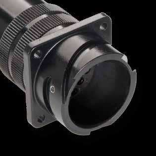
CVBS Series Code
Available in several versions suitable for all applications and manufactured in different materials and finishes:
• Aluminum alloy with different types of protection finishes according to RoHS directives.
CVBS Bayonet Connector with protected mating ramps
Shell Material - Aluminum
00 Shell Type xx
Flange/Plug Shell with ramp/threaded or with nut
DA Connector Class xx With backshell
T With plastic caps
FF
T Connector Modification**
Receptacle connector with threaded holes (to specify for 00/02/05 shell only)
FP Receptacle connector with through holes (to specify for 03 shell only)
FS Receptacle connector with countersunk holes
V Insert and contacts sealed (solder only)
PG16 Backshell Conduits size or internal thread - Without internal thread xx Conduits size or internal thread
F4 CCF - Green passivation - conductive
F5 Electroless nickel (RoHS compliance)
F7 Shell finish
F7 Black epoxy varnish (RoHS compliance)
F16 CCF - Black passivation - conductive (RoHS compliance)
F26 Hard anodization (RoHS compliance)
G Panel Gasket - Without gasket
G With waterproof panel gasket
G2 With shielded panel gasket
G3 With waterproof shielded panel gasket
N Contacts and hole plugs (Consult our sales office)
N Modification Code**
S Customization (Consult our sales office)
69 Go online for data sheets & assembly instructions. Visit www.radiall.com/vansystem and enter the part number.
CVBS SHELL
RF CVBS 00 DA 20-27 S X PG16 CR CD5 F7 G N T
CVBS - Bayonet Connector with protected mating ramps
Front Mounting Receptacle (00) with Backshell Class (A - DA - RA)
Connector with backshell provided with an external thread suitable for MS3057…A or C type Cable-Clamps (to be ordered separately).
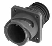
Panel cut out
For installation with backshell mounted, consult our sales office.
Dimension “L” can be different from the value indicated according to backshells accessories, wires size and some special
70 Go online for data sheets & assembly instructions. Visit www.radiall.com/vansystem and enter the part number. CVBS SHELL
ØB N T S R K M ØD L Shell size ØD +0 -0.15 ØB ±0.2 L M ±0.2 K ±0.2 N Backshell Thread in inches R ±0.1 S ±0.3 ØT ±0.2 ØT1 Through holes ØC* ±0.2 10SL 18.2 20 41 14.2 2.8 5/8”-24 UNEF 18.2 25.4 3.1 3.4 17 14S 24.6 24 42.5 14.5 3.2 3/4”-20 UNEF 23 30.2 3.1 3.4 20 16S 27.4 27 42.5 14.2 3.2 7/8”-20 UNEF 24.6 32.5 3.1 3.4 23 16 27.4 27 50 19 3.2 7/8”-20 UNEF 24.6 32.5 3.1 3.4 23 18 30.8 30 52 19 4 1”-20 UNEF 27 34.9 3.1 3.4 26.5 20 34.2 32 51 19 4 1” 3/16-18 UNEF 29.4 38.1 3.1 3.4 30 22 37.4 37 54 19.7 4 1” 3/16-18 UNEF 31.8 41 3.1 3.4 33 24 40.9 40 54 20.6 4 1” 7/16-18 UNEF 34.9 44.5 3.7 3.9 36 28 46.7 45 62 20.6 4 1” 7/16-18 UNEF 39.7 50.8 3.7 3.9 42 32 53.4 52 63 22.2 4 1” 3/4-18 UNS 44.5 57 4.4 4.5 48.5 36 59.6 58 63 22.2 4 2”-18 UNS 49.2 63.5 4.4 4.5 55 40 65.5 63.2 63 22.2 4 2”1/4-16 UN 55.6 69.8 4.4 4.5 61
Dimensions in mm R ØC ØT 1
*
insert configurations.
*
CVBS - Bayonet Connector with protected mating ramps
RF Insulating material
CVBS Series Code
- Chloroprene rubber
V Fluoride rubber
S Silicone rubber
RF Fire resistant rubber
Bayonet Connector with protected mating ramps Shell Material - Aluminum
DA Connector Class
T Connector Modification**
non watertight DA with waterproof O-ring (IP67***) RA with waterproof O-ring and grommet (IP67***)
T With plastic caps
FF Receptacle connector with threaded holes
Receptacle connector with through holes
FS Receptacle connector with countersunk holes
20-27 Insert Arrangement Size - Type
S Contact Gender S Socket contacts
P Pin contacts
X Polarization Code** Alternate Positions
CR Contact Termination
CD5 Contact Plating
F7 Shell finish
- Solder contacts
CR Crimp contacts
LC Less contacts
- Silver plating
CD5 Gold plating
F5 Electroless nickel (*)
F7 Black epoxy varnish (*)
F16
G Panel Gasket
CCF - Black passivation (*) - conductive
F26 hard anodization (*)
- Without gasket
G With waterproof panel gasket
G2 With shielded panel gasket
G3 With waterproof shielded panel gasket
N Modification Code** N
Consult our sales office S
71 Go online for data sheets & assembly instructions. Visit www.radiall.com/vansystem and enter the part number. CVBS SHELL
Shell
ØB N
Series Code Shell Type Connector Class
finish
Backshell Grommet cone (RA Class only) Grommet (RA Class only) Gasket (DA-RA Class only) P/N Sample: RF CVBS 00DAT 20-27SX CR CD5 F7 G N RF CVBS 00 DA 20-27 S X CR CD5 F7 G N T
(*) RoHS compliance (**) If required ***
60529
Shell Material
Protection degree: IP 67 (only in the mating area with mated connectors) according to EN
Type 00
CVBS
00 Shell
Front mounting Receptacle
A
CVBS - Bayonet Connector with protected mating ramps
Front Mounting Receptacle (00) with Backshell Class (LA - LDA - LRA)
Connector with long backshell provided with an external thread suitable for MS3057…A or C type Cable-Clamps (to be ordered separately).
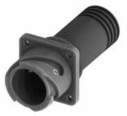
cut out
For installation with backshell mounted, consult our sales office.
72 Go online for data sheets & assembly instructions. Visit www.radiall.com/vansystem and enter the part number. CVBS SHELL
ØB N T K M ØD S R L Shell size ØD +0 -0.15 ØB ±0.2 L M ±0.2 K ±0.2 N Backshell Thread in inches R ±0.1 S ±0.3 ØT ±0.2 ØT1 Through holes ØC* ±0.2 10SL 18.2 20 67 14.2 2.8 5/8”-24 UNEF 18.2 25.4 3.1 3.4 17 14S 24.6 24 67 14.5 3.2 3/4”-20 UNEF 23 30.2 3.1 3.4 20 16S 27.4 27 67 14.2 3.2 7/8”-20 UNEF 24.6 32.5 3.1 3.4 23 16 27.4 27 77 19 3.2 7/8”-20 UNEF 24.6 32.5 3.1 3.4 23 18 30.8 30 77.5 19 4 1”-20 UNEF 27 34.9 3.1 3.4 26.5 20 34.2 32 78 19 4 1” 3/16-18 UNEF 29.4 38.1 3.1 3.4 30 22 37.4 37 79 19.7 4 1” 3/16-18 UNEF 31.8 41 3.1 3.4 33 24 40.9 40 81 20.6 4 1” 7/16-18 UNEF 34.9 44.5 3.7 3.9 36 28 46.7 45 81 20.6 4 1” 7/16-18 UNEF 39.7 50.8 3.7 3.9 42 32 53.4 52 95.5 22.2 4 1” 3/4-18 UNS 44.5 57 4.4 4.5 48.5 36 59.6 58 95.5 22.2 4 2”-18 UNS 49.2 63.5 4.4 4.5 55 40 65.5 63.2 95.5 22.2 4 2”1/4-16 UN 55.6 69.8 4.4 4.5 61
insert
Dimensions in mm R ØC ØT 1
* *
Dimension “L” can be different from the value indicated according to backshells accessories, wires size and some special
configurations.
Panel
CVBS - Bayonet Connector with protected mating ramps
RF Insulating material
- Chloroprene rubber V Fluoride rubber S Silicone rubber
RF Fire resistant rubber CVBS Series Code
with protected mating ramps Shell Material
LDA Connector Class LA non watertight
LDA with waterproof O-ring (IP67***)
LRA with waterproof O-ring and grommet (IP67***)
T With plastic caps
FF Receptacle connector with threaded holes
T Connector Modification**
Receptacle connector with through holes
FS Receptacle connector with countersunk holes
CD5 Contact Plating
F7 Shell finish
- Solder contacts
CR Crimp contacts
LC Less contacts
- Silver plating
CD5 Gold plating
F5 Electroless nickel (*)
F7 Black epoxy varnish (*)
F16
20-27 Insert Arrangement Size - Type S Contact Gender S Socket contacts P Pin contacts X Polarization Code** Alternate Positions CR Contact Termination
CCF - Black passivation (*) - conductive
F26 hard anodization (*)
G Panel Gasket - Without gasket
G With waterproof panel gasket
G2 With shielded panel gasket
G3 With waterproof shielded panel gasket N Modification Code** N Consult our sales office S
73 Go online for data sheets & assembly instructions. Visit www.radiall.com/vansystem and enter the part number.
SHELL ØB N
CVBS
Grommet
only) Grommet
only) Gasket (LDA-LRA Class only)
Backshell
cone (LRA Class
(LRA Class
CVBS 00LDAT 20-27SX CR CD5 F7 G N
Shell Type Connector Class Shell finish RF CVBS 00 LDA 20-27 S X CR CD5 F7 G N T Shell Material (*)
required ***
P/N Sample: RF
Series Code
RoHS compliance (**) If
Protection degree: IP 67 (only in the mating area with mated connectors) according to EN 60529
00
CVBS Bayonet Connector
- Aluminum 00 Shell Type
Front mounting Receptacle
CVBS - Bayonet Connector with protected mating ramps
Front Mounting Receptacle (00) with Backshell Class (AF - F)
Connector provided with backshell, MS3057...A type Cable-Clamp and bushing MS3420... (for single wire)
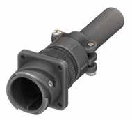
Panel cut out
* For installation with backshell mounted, consult our
Dimension “L” can be different from the value indicated according to backshells accessories, wires size and some special insert configurations.
74 Go online for data sheets & assembly instructions. Visit www.radiall.com/vansystem and enter the part number. CVBS SHELL
A F Ø T S R ØB K M L D Shell size ØD +0 -0.15 ØB ±0.2 L M ±0.2 K ±0.2 A max ØF cable max dimension R ±0.1 S ±0.3 ØT ±0.2 ØT1 Through holes ØC* ±0.2 10SL 18.2 20 51 14.2 2.8 22.5 5.6 18.2 25.4 3.1 3.4 17 14S 24.6 24 54.5 14.5 3.2 28 7.9 23 30.2 3.1 3.4 20 16S 27.4 27 56 14.2 3.2 30 11 24.6 32.5 3.1 3.4 23 16 27.4 27 63.5 19 3.2 30 11 24.6 32.5 3.1 3.4 23 18 30.8 30 66.5 19 4 31.7 14.2 27 34.9 3.1 3.4 26.5 20 34.2 32 66.5 19 4 37.5 15.8 29.4 38.1 3.1 3.4 30 22 37.4 37 69.5 19.7 4 37.5 15.8 31.8 41 3.1 3.4 33 24 40.9 40 69.5 20.6 4 43.5 19 34.9 44.5 3.7 3.9 36 28 46.7 45 77.5 20.6 4 43.5 19 39.7 50.8 3.7 3.9 42 32 53.4 52 78.5 22.2 4 51.7 23.8 44.5 57 4.4 4.5 48.5 36 59.6 58 78.5 22.2 4 58.5 31.7 49.2 63.5 4.4 4.5 55 40 65.5 63.2 92 22.2 4 68.5 34.9 55.6 69.8 4.4 4.5 61
R ØC ØT 1
Dimensions in mm
IP54 *
sales office.
CVBS - Bayonet Connector with protected mating ramps
Grommet (F Class only) Gasket
Grommet cone (F Class only)
V Fluoride rubber
RF Insulating material - Chloroprene rubber
S Silicone rubber
RF Fire resistant rubber CVBS Series Code CVBS Bayonet Connector with protected mating ramps
AF Connector Class F with waterproof O-ring and grommet (IP54)
AF with waterproof O-ring (IP54)
T With plastic caps
FF Receptacle connector with threaded holes
T Connector Modification**
Receptacle connector with through holes
FS Receptacle connector with countersunk holes
P Pin contacts
X Polarization Code** Alternate Positions
CR Contact Termination
CD5 Contact Plating
G Panel Gasket
- Solder contacts
CR Crimp contacts
LC Less contacts
- Silver plating
CD5 Gold plating F7 Shell finish
F5
F16
20-27 Insert Arrangement Size - Type S Contact Gender S Socket contacts
Electroless nickel (*)
F7 Black epoxy varnish (*)
CCF - Black passivation (*) - conductive
F26 hard anodization (*)
- Without gasket
G With waterproof panel gasket
G2 With shielded panel gasket
G3 With waterproof shielded panel gasket
N Modification Code** N
Consult our sales office S
75 Go online for data sheets & assembly instructions. Visit www.radiall.com/vansystem and enter the part number.
SHELL
CVBS
Backshell
(*) RoHS compliance
RF CVBS 00AFT 20-27SX CR CD5 F7 G N H A F Ø ØB ØB A F Ø
P/N Sample:
Class Shell finish RF CVBS 00 AF 20-27 S X CR CD5 F7 G N T
Cable-Clamp
MS3057...A bushing MS3420 Series Code Shell Type Connector
Shell Material (**) If required
00
Shell Material - Aluminum 00 Shell Type
Front mounting Receptacle
CVBS - Bayonet Connector with protected mating ramps
Front Mounting Receptacle (00) with Backshell Class (LAF - LF)
Connector provided with long backshell, MS3057...A type Cable-Clamp and bushing MS3420... (for single wire)
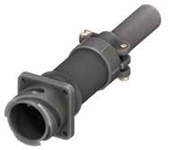
Panel cut out
For installation with backshell mounted,
Dimension “L” can be different from the value indicated according to backshells accessories, wires size and some special insert configurations. Dimensions in
76 Go online for data sheets & assembly instructions. Visit www.radiall.com/vansystem and enter the part number. CVBS SHELL
K M L D A F Ø T S R ØB Shell size ØD +0 -0.15 ØB ±0.2 L M ±0.2 K ±0.2 A max ØF cable max dimension R ±0.1 S ±0.3 ØT ±0.2 ØT1 Through holes ØC* ±0.2 10SL 18.2 20 77 14.2 2.8 22.5 5.6 18.2 25.4 3.1 3.4 17 14S 24.6 24 79 14.5 3.2 28 7.9 23 30.2 3.1 3.4 20 16S 27.4 27 80.5 14.2 3.2 30 11 24.6 32.5 3.1 3.4 23 16 27.4 27 90.5 19 3.2 30 11 24.6 32.5 3.1 3.4 23 18 30.8 30 93 19 4 31.7 14.2 27 34.9 3.1 3.4 26.5 20 34.2 32 93.5 19 4 37.5 15.8 29.4 38.1 3.1 3.4 30 22 37.4 37 94.5 19.7 4 37.5 15.8 31.8 41 3.1 3.4 33 24 40.9 40 96.5 20.6 4 43.5 19 34.9 44.5 3.7 3.9 36 28 46.7 45 96.5 20.6 4 43.5 19 39.7 50.8 3.7 3.9 42 32 53.4 52 111 22.2 4 51.7 23.8 44.5 57 4.4 4.5 48.5 36 59.6 58 111 22.2 4 58.5 31.7 49.2 63.5 4.4 4.5 55 40 65.5 63.2 124.5 22.2 4 68.5 34.9 55.6 69.8 4.4 4.5 61
R ØC ØT 1
mm
IP54 *
consult our sales office.
*
CVBS - Bayonet Connector with protected mating ramps
RF Insulating material - Chloroprene rubber
V Fluoride rubber
S Silicone rubber
RF Fire resistant rubber
CVBS Series Code CVBS Bayonet Connector with protected mating ramps
LAF Connector Class
T Connector Modification**
LF with waterproof O-ring and grommet (IP54) LAF with waterproof O-ring (IP54)
T With plastic caps
FF Receptacle connector with threaded holes
Receptacle connector with through holes
FS Receptacle connector with countersunk holes
20-27 Insert Arrangement Size - Type
S Contact Gender S Socket contacts P Pin contacts
X Polarization Code** Alternate Positions
CR Contact Termination
CD5 Contact Plating
- Solder contacts
CR Crimp contacts
LC Less contacts
- Silver plating
CD5 Gold plating F7 Shell finish
F5
Electroless nickel (*)
F7 Black epoxy varnish (*)
F16
G Panel Gasket
CCF - Black passivation (*) - conductive
F26 hard anodization (*)
- Without gasket
G With waterproof panel gasket
G2 With shielded panel gasket
G3 With waterproof shielded panel gasket
N Modification Code** N
Consult our sales office S
77 Go online for data sheets & assembly instructions. Visit www.radiall.com/vansystem and enter the part number.
SHELL
CVBS
Grommet
Gasket (*) RoHS compliance
Backshell
Grommet cone (LF Class only)
(LF Class only)
RF CVBS 00LAFT 20-27SX CR CD5 F7 G N
bushing MS3420
P/N Sample:
Cable-Clamp MS3057...A
Shell finish RF CVBS 00 LAF 20-27 S X CR CD5 F7 G N T
required
Series Code Shell Type Connector Class
Shell Material (**) If
00
Shell Material - Aluminum 00 Shell Type
Front mounting Receptacle
CVBS - Bayonet Connector with protected mating ramps
Front Mounting Receptacle (00) with Backshell Class (AC - ACF)
Connector provided with backshell, MS3057...C type Cable-Clamp (for jacketed cable)
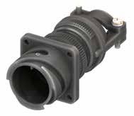
Dimension “L” can be different from the value indicated according to backshells accessories, wires size and some special insert configurations.
78 Go online for data sheets & assembly instructions. Visit www.radiall.com/vansystem and enter the part number. CVBS SHELL
A Ø F T S R K M D L ØB Shell size ØD +0 -0.15 ØB ±0.2 L K ±0.2 M ±0.2 A ±0.2 ØF cable dimension R ±0.1 S ±0.3 ØT ±0.2 ØT1 Through holes ØC* ±0.2 Min Max 10SL 18.2 20 65 2.8 14.2 23 2.4 7.9 18.2 25.4 3.1 3.4 17 14S 24.6 24 66.5 3.2 14.5 26 5.8 11.2 23 30.2 3.1 3.4 20 16S 27.4 27 67.5 3.2 14.2 28.5 8 13.5 24.6 32.5 3.1 3.4 23 16 27.4 27 75 3.2 19 28.5 8 13.5 24.6 32.5 3.1 3.4 23 18 30.8 30 78.5 4 19 32 9.6 15.9 27 34.9 3.1 3.4 26.5 20 34.2 32 77.5 4 19 37.5 11.3 19 29.4 38.1 3.1 3.4 30 22 37.4 37 80.5 4 19.7 37.5 11.3 19 31.8 41 3.1 3.4 33 24 40.9 40 87.5 4 20.6 43.5 15.5 23.8 34.9 44.5 3.7 3.9 36 28 46.7 45 95.5 4 20.6 43.5 15.5 23.8 39.7 50.8 3.7 3.9 42 32 53.4 52 101 4 22.2 54 23.4 31.8 44.5 57 4.4 4.5 48.5 36 59.6 58 105.5 4 22.2 58 25.4 35 49.2 63.5 4.4 4.5 55 40 65.5 63.2 107 4 22.2 63.5 30 41.3 55.6 69.8 4.4 4.5 61
Dimensions in mm R ØC ØT 1 Panel
IP67 * *
consult our sales office.
cut out
For installation with backshell mounted,
CVBS - Bayonet Connector with protected mating ramps
Grommet cone (ACF Class only)
Grommet (ACF Class only) Gasket
Backshell
RF Insulating material - Chloroprene rubber
V Fluoride rubber
S Silicone rubber
RF Fire resistant rubber
CVBS Series Code CVBS Bayonet Connector with protected mating ramps
AC Connector Class
T Connector Modification**
ACF with waterproof O-ring and grommet (IP67)
AC with waterproof O-ring (IP67)
T With plastic caps
FF Receptacle connector with threaded holes
Receptacle connector with through holes
FS Receptacle connector with countersunk holes
20-27 Insert Arrangement Size - Type
S Contact Gender S Socket contacts P Pin contacts
X Polarization Code** Alternate Positions
CR Contact Termination
CD5 Contact Plating
- Solder contacts
CR Crimp contacts
LC Less contacts
- Silver plating
CD5 Gold plating F7 Shell finish
F5
Electroless nickel (*)
F7 Black epoxy varnish (*)
F16
G Panel Gasket
CCF - Black passivation (*) - conductive
F26 hard anodization (*)
- Without gasket
G With waterproof panel gasket
G2 With shielded panel gasket
G3 With waterproof shielded panel gasket
N Modification Code** N
Consult our sales office S
79 Go online for data sheets & assembly instructions. Visit www.radiall.com/vansystem and enter the part number.
SHELL
CVBS
(*) RoHS compliance
RF CVBS 00ACT 20-27SX CR CD5 F7 G N A Ø F ØB H
P/N Sample:
Cable-Clamp MS3057...C
Shell finish RF CVBS 00 AC 20-27 S X CR CD5 F7 G N T
Series Code Shell Type Connector Class
Shell Material (**) If required
Shell Material - Aluminum 00 Shell Type 00 Front mounting Receptacle
CVBS - Bayonet Connector with protected mating ramps
Front Mounting Receptacle (00) with Backshell Class (ACB)
Connector provided with backshell, MS3057...C type Cable-Clamp and bushing MS 3420A (for jacketed cable)
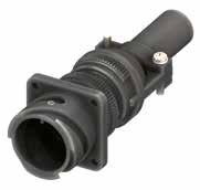
Panel cut out
* For installation with backshell mounted,
Dimension “L” can be different from the value indicated according to backshells accessories, wires size and some special insert configurations.
80 Go online for data sheets & assembly instructions. Visit www.radiall.com/vansystem and enter the part number. CVBS SHELL
L ØB A F Ø K M D T S R Shell size ØD +0 -0.15 ØB ±0.2 L K ±0.2 M ±0.2 A ±0.2 ØF max cable size R ±0.1 S ±0.3 ØT ±0.2 ØT1 Through holes ØC* ±0.2 10SL 18.2 20 65 2.8 14.2 23 5.6 18.2 25.4 3.1 3.4 17 14S 24.6 24 66.5 3.2 14.5 26 7.9 23 30.2 3.1 3.4 20 16S 27.4 27 67.5 3.2 14.2 28.5 11.1 24.6 32.5 3.1 3.4 23 16 27.4 27 75 3.2 19 28.5 11.1 24.6 32.5 3.1 3.4 23 18 30.8 30 78.5 4 19 32 11.1 27 34.9 3.1 3.4 26.5 20 34.2 32 77.5 4 19 37.5 13.7 29.4 38.1 3.1 3.4 30 22 37.4 37 80.5 4 19.7 37.5 13.7 31.8 41 3.1 3.4 33 24 40.9 40 87.5 4 20.6 43.5 19 34.9 44.5 3.7 3.9 36 28 46.7 45 95.5 4 20.6 43.5 19 39.7 50.8 3.7 3.9 42 32 53.4 52 101 4 22.2 54 23.8 44.5 57 4.4 4.5 48.5 36 59.6 58 105.5 4 22.2 58 28.5 49.2 63.5 4.4 4.5 55 40 65.5 63.2 107 4 22.2 63.5 31.8 55.6 69.8 4.4 4.5 61
R ØC ØT 1
Dimensions in mm
*
consult our sales office.
CVBS - Bayonet Connector with protected mating ramps
RF Insulating material
Backshell Gasket
- Chloroprene rubber
V Fluoride rubber
S Silicone rubber
RF Fire resistant rubber
CVBS Series Code CVBS Bayonet Connector with protected mating ramps
Shell Material - Aluminum 00 Shell Type
ACB Connector Class ACB with waterproof O-ring
T With plastic caps
FF Receptacle connector with threaded holes
S Contact Gender S Socket contacts P Pin contacts
X Polarization Code**
CR Contact Termination
CD5 Contact Plating
F7 Shell finish
Alternate Positions
- Solder contacts
CR Crimp contacts
LC Less contacts
- Silver plating
CD5 Gold plating
F5 Electroless nickel (*)
F7 Black epoxy varnish (*)
F16
T Connector Modification**
Receptacle connector with through holes
FS Receptacle connector with countersunk holes
20-27 Insert Arrangement Size - Type
P/N Sample:
G Panel Gasket
N Modification Code**
CCF - Black passivation (*) - conductive
F26 hard anodization (*)
- Without gasket
G With waterproof panel gasket
G2 With shielded panel gasket
G3 With waterproof shielded panel gasket
Consult our sales office
(**) If required
81 Go online for data sheets & assembly instructions. Visit www.radiall.com/vansystem and enter the part number.
SHELL
CVBS
(*)
RoHS compliance
RF CVBS 00ACBT 20-27SX CR CD5 F7 G N ØB A F Ø Cable-Clamp MS3057...C
RF CVBS 00 ACB 20-27 S X CR CD5 F7 G N T
Series Code Shell Type Connector Class Shell finish
Shell Material bushing MS3420A
00 Front mounting Receptacle
N
S
CVBS - Bayonet Connector with protected mating ramps
Front Mounting Receptacle (00) with Backshell Class (LAC - LACF)
Connector provided with long backshell, MS3057...C type Cable-Clamp (for jacketed cable)
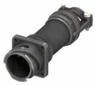
Panel cut out
For installation with backshell mounted, consult
Dimension “L” can be different from the value indicated according to backshells accessories, wires size and some special insert configurations.
82 Go online for data sheets & assembly instructions. Visit www.radiall.com/vansystem and enter the part number. CVBS SHELL
K M D L ØB A Ø F T S R Shell size ØD +0 -0.15 ØB ±0.2 K ±0.2 L M ±0.2 A ±0.2 ØF cable dimension R ±0.1 S ±0.3 ØT ±0.2 ØT1 Through holes ØC* ±0.2 Min Max 10SL 18.2 20 2.8 91 14.2 23 2.4 7.9 18.2 25.4 3.1 3.4 17 14S 24.6 24 3.2 91 14.5 26 5.8 11.2 23 30.2 3.1 3.4 20 16S 27.4 27 3.2 92 14.2 28.5 8 13.5 24.6 32.5 3.1 3.4 23 16 27.4 27 3.2 102 19 28.5 8 13.5 24.6 32.5 3.1 3.4 23 18 30.8 30 4 105 19 32 9.6 15.9 27 34.9 3.1 3.4 26.5 20 34.2 32 4 105 19 37.5 11.3 19 29.4 38.1 3.1 3.4 30 22 37.4 37 4 106 19.7 37.5 11.3 19 31.8 41 3.1 3.4 33 24 40.9 40 4 114.5 20.6 43.5 15.5 23.8 34.9 44.5 3.7 3.9 36 28 46.7 45 4 114.5 20.6 43.5 15.5 23.8 39.7 50.8 3.7 3.9 42 32 53.4 52 4 133.5 22.2 54 23.4 31.8 44.5 57 4.4 4.5 48.5 36 59.6 58 4 138 22.2 58 25.4 35 49.2 63.5 4.4 4.5 55 40 65.5 63.2 4 139.5 22.2 63.5 30 41.3 55.6 69.8 4.4 4.5 61
mm R ØC ØT 1
IP67 * *
office.
Dimensions in
our sales
CVBS - Bayonet Connector with protected mating ramps
Backshell Grommet cone (LACF Class only) Grommet (LACF Class only) Gasket
RF Insulating material
- Chloroprene rubber
V Fluoride rubber
S Silicone rubber
RF Fire resistant rubber
CVBS Series Code CVBS Bayonet Connector with protected mating ramps
Shell Material - Aluminum
00 Shell Type 00 Front mounting Receptacle
LAC Connector Class
T Connector Modification**
LACF with waterproof O-ring and grommet (IP67)
LAC with waterproof O-ring (IP67)
T With plastic caps
FF Receptacle connector with threaded holes
Receptacle connector with through holes
FS Receptacle connector with countersunk holes
X Polarization Code**
CR Contact Termination
CD5 Contact Plating
G Panel Gasket
Alternate Positions
- Solder contacts
CR Crimp contacts
LC Less contacts
- Silver plating
CD5 Gold plating F7 Shell finish
F5 Electroless nickel (*)
F7 Black epoxy varnish (*)
F16
20-27 Insert Arrangement Size - Type S Contact Gender S Socket contacts P Pin contacts
CCF - Black passivation (*) - conductive
F26 hard anodization (*)
- Without gasket
G With waterproof panel gasket
G2 With shielded panel gasket
G3 With waterproof shielded panel gasket
N Modification Code** N Consult our sales office S
83 Go online for data sheets & assembly instructions. Visit www.radiall.com/vansystem and enter the part number.
SHELL
CVBS
(*) RoHS compliance
RF CVBS 00LACT 20-27SX CR CD5 F7 G N A Ø F ØB
MS3057...C
Class Shell finish RF CVBS 00 LAC 20-27 S X CR CD5 F7 G N T Shell Material
P/N Sample:
Cable-Clamp
Series Code Shell Type Connector
(**) If required
CVBS - Bayonet Connector with protected mating ramps
Front Mounting Receptacle (00) with Backshell Class (AB)
Connector provided with backshell, MS3057...B type Cable-Clamp (for jacketed cable)
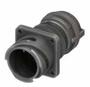
Panel cut out
For installation with backshell mounted, consult our sales office.
Dimension “L” can be different from the value indicated according to backshells accessories, wires size and some special insert configurations.
84 Go online for data sheets & assembly instructions. Visit www.radiall.com/vansystem and enter the part number. CVBS SHELL
L ØB A Ø F K M D T S R Shell size ØD +0 -0.15 ØB ±0.2 L K ±0.2 M ±0.2 A ±0.2 ØF cable dimension R ±0.1 S ±0.3 ØT ±0.2 ØT1 Through holes ØC* ±0.2 Min Max 10SL 18.2 20 48.4 2.8 14.2 23 2.4 7.9 18.2 25.4 3.1 3.4 17 14S 24.6 24 56.1 3.2 14.5 26 5.8 11.2 23 30.2 3.1 3.4 20 16S 27.4 27 57.3 3.2 14.2 28.5 8 13.5 24.6 32.5 3.1 3.4 23 16 27.4 27 63.3 3.2 19 28.5 8 13.5 24.6 32.5 3.1 3.4 23 18 30.8 30 68 4 19 32 9.6 15.9 27 34.9 3.1 3.4 26.5 20 34.2 32 69.2 4 19 37.5 11.3 19 29.4 38.1 3.1 3.4 30 22 37.4 37 71.2 4 19.7 37.5 11.3 19 31.8 41 3.1 3.4 33 24 40.9 40 76.3 4 20.6 43.5 15.5 23.8 34.9 44.5 3.7 3.9 36 28 46.7 45 83.3 4 20.6 43.5 15.5 23.8 39.7 50.8 3.7 3.9 42 32 53.4 52 85.1 4 22.2 54 23.4 31.8 44.5 57 4.4 4.5 48.5 36 59.6 58 88.2 4 22.2 58 25.4 35 49.2 63.5 4.4 4.5 55 40 65.5 63.2 91.5 4 22.2 63.5 30 41.3 55.6 69.8 4.4 4.5 61
Dimensions in mm R ØC ØT 1
* *
CVBS - Bayonet Connector with protected mating ramps
Shell Material
RF Insulating material
Backshell Gasket
- Chloroprene rubber
V Fluoride rubber
S Silicone rubber
RF Fire resistant rubber
CVBS Series Code CVBS Bayonet Connector with protected mating ramps
Shell Material - Aluminum
00 Shell Type 00
Front mounting Receptacle
AB Connector Class AB with waterproof O-ring
T With plastic caps
FF Receptacle connector with threaded holes
S Contact Gender S Socket contacts P Pin contacts
X Polarization Code**
CR Contact Termination
CD5 Contact Plating
F7 Shell finish
Alternate Positions
- Solder contacts
CR Crimp contacts
LC Less contacts
- Silver plating
CD5 Gold plating
F5 Electroless nickel (*)
F7 Black epoxy varnish (*)
F16
T Connector Modification**
Receptacle connector with through holes
FS Receptacle connector with countersunk holes
20-27 Insert Arrangement Size - Type
P/N Sample:
G Panel Gasket
N Modification Code**
CCF - Black passivation (*) - conductive
F26 hard anodization (*)
- Without gasket
G With waterproof panel gasket
G2 With shielded panel gasket
G3 With waterproof shielded panel gasket
Consult our sales office
(**) If required
85 Go online for data sheets & assembly instructions. Visit www.radiall.com/vansystem and enter the part number.
SHELL
CVBS
(*) RoHS compliance
RF CVBS 00ABT 20-27SX CR CD5 F7 G N A Ø F ØB
Cable-Clamp MS3057..B
RF CVBS 00 AB 20-27 S X CR CD5 F7 G N T
Series Code Shell Type Connector Class Shell finish
N
S
CVBS - Bayonet Connector with protected mating ramps
Front Mounting Receptacle (00) with Backshell Class (ASF)
Connector provided with backshell, MS3057...A type Cable-Clamp (for single wire)
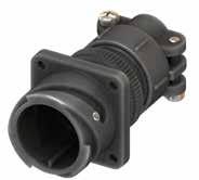
Panel cut out
* For installation with backshell mounted, consult our sales office.
Dimension “L” can be different from the value indicated according to backshells accessories, wires size and some special insert configurations.
86 Go online for data sheets & assembly instructions. Visit www.radiall.com/vansystem and enter the part number. CVBS SHELL
L ØB A F Ø K M D T S R Shell size ØD +0 -0.15 ØB ±0.2 L K ±0.2 M ±0.2 A max ØF cable max dimension R ±0.1 S ±0.3 ØT ±0.2 ØT1 Through holes ØC* ±0.2 10SL 18.2 20 51 2.8 14.2 22.5 8 18.2 25.4 3.1 3.4 17 14S 24.6 24 54.5 3.2 14.5 28 11 23 30.2 3.1 3.4 20 16S 27.4 27 56 3.2 14.2 30 14.2 24.6 32.5 3.1 3.4 23 16 27.4 27 63.5 3.2 19 30 14.2 24.6 32.5 3.1 3.4 23 18 30.8 30 66.5 4 19 31.7 15.8 27 34.9 3.1 3.4 26.5 20 34.2 32 66.5 4 19 37.5 19 29.4 38.1 3.1 3.4 30 22 37.4 37 69.5 4 19.7 37.5 19 31.8 41 3.1 3.4 33 24 40.9 40 69.5 4 20.6 43.5 23.8 34.9 44.5 3.7 3.9 36 28 46.7 45 77.5 4 20.6 43.5 23.8 39.7 50.8 3.7 3.9 42 32 53.4 52 78.5 4 22.2 51.7 31.7 44.5 57 4.4 4.5 48.5 36 59.6 58 78.5 4 22.2 58.5 35 49.2 63.5 4.4 4.5 55 40 65.5 63.2 92 4 22.2 68.5 41.2 55.6 69.8 4.4 4.5 61
Dimensions in mm R ØC ØT 1
*
CVBS - Bayonet Connector with protected mating ramps
Series Code Shell Type Connector Class Shell finish
RF Insulating material
- Chloroprene rubber
V Fluoride rubber
S Silicone rubber
RF Fire resistant rubber
CVBS Series Code CVBS Bayonet Connector with protected mating ramps
Shell Material - Aluminum
00 Shell Type 00 Front mounting Receptacle
ASF Connector Class ASF with waterproof O-ring and grommet
T With plastic caps
FF Receptacle connector with threaded holes
T Connector Modification**
Receptacle connector with through holes
FS Receptacle connector with countersunk holes
20-27 Insert Arrangement Size - Type
P/N Sample: RF CVBS 00ASFT 20-27SX CR CD5 F7 G N
Shell Material (**) If required
S Contact Gender S Socket contacts P Pin contacts X Polarization Code**
CR Contact Termination
CD5 Contact Plating
F7 Shell finish
G Panel Gasket
Alternate Positions
- Solder contacts
CR Crimp contacts
LC Less contacts
- Silver plating
CD5 Gold plating
F5 Electroless nickel (*)
F7 Black epoxy varnish (*)
F16
CCF - Black passivation (*) - conductive
F26 hard anodization (*)
- Without gasket
G With waterproof panel gasket
G2 With shielded panel gasket
G3 With waterproof shielded panel gasket N Modification Code** N Consult our sales office
(*) RoHS compliance
87 Go online for data sheets &
Visit www.radiall.com/vansystem and enter the part number.
assembly instructions.
SHELL
CVBS
ASF 20-27 S X CR CD5 F7 G N T
RF CVBS 00
S
ØB A F Ø
Backshell
Cable-Clamp MS3057...A Grommet cone Grommet Gasket
CVBS - Bayonet Connector with protected mating ramps
Front Mounting Receptacle (00) with Backshell Class (DA..M - RA..M DA..PG - RA..PG)
Connector with backshell provided with an internal Metric or PG thread suitable for Cable Glands or conduit adapters.
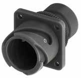
Panel cut out
* For installation with backshell mounted, consult our sales office.
Dimensions “L1 and L2” can be different from the value indicated according to backshells accessories, wires size and some special insert configurations.
(...) The threads in parentheses are versions on request with non standard backshell length (the dimensions L2 and Z are different from this page indication). Please consult our sales office for the specific dimensions.
88 Go online for data sheets & assembly instructions. Visit www.radiall.com/vansystem and enter the part number. CVBS SHELL
ØB N T K M ØD S R Z L2 L1 Shell size ØD +0 -0.15 ØB ±0.2 M ±0.2 K ±0.2 Z min L1 N Backshell Metric thread L2 M N Backshell PG Thread L2 PG R ±0.1 S ±0.3 ØT ±0.2 ØT1 Through holes ØC* ±0.2 10SL 18.2 20 14.2 2.8 8 18,2 M12 - M16 32 (PG9) - PG13.5 26 18.2 25.4 3.1 3.4 17 14S 24.6 24 14.5 3.2 9 19,3 M12 - M16 - (M20) - (M25) 30 (PG9) - PG11 - PG13.5 - (PG16) 30 23 30.2 3.1 3.4 20 16S 27.4 27 14.2 3.2 9 18,5 (M16) - M20 40 PG13.5 - (PG16) 38 24.6 32.5 3.1 3.4 23 16 27.4 27 19 3.2 9 24,4 M20 45 - 40 24.6 32.5 3.1 3.4 23 18 30.8 30 19 4 9 24 M20 - M25 50 (PG11) - (PG13.5) - PG16 - PG21 50 27 34.9 3.1 3.4 26.5 20 34.2 32 19 4 9 24,2 M16 - M20 - M25 - (M32) 50 PG11-PG13.5-PG16-PG21-PG29 50 29.4 38.1 3.1 3.4 30 22 37.4 37 19.7 4 10 24,5 M16 - M20 - M25 - M32 50 PG13.5 - (PG16) - (PG29) 50 31.8 41 3.1 3.4 33 24 40.9 40 20.6 4 10 25,7 M20 - M25 - M32 - M40 50 PG16 - PG21 - PG29 50 34.9 44.5 3.7 3.9 36 28 46.7 45 20.6 4 10 26,1 (M25) - M32 - M40 63 PG21 - PG29 - PG36 60 39.7 50.8 3.7 3.9 42 32 53.4 52 22.2 4 10 27,9 (M25) - (M32) - M40 55 PG21 - (PG29) - PG36 60 44.5 57 4.4 4.5 48.5 36 59.6 58 22.2 4 13 28,7 M40 - M50 56 PG29 - (PG36) - (PG42) 65 49.2 63.5 4.4 4.5 55 40 65.5 63.2 22.2 4 13 28 M40 - (M50) - M63 65 PG29 - (PG36) - (PG42) - (PG48) 65 55.6 69.8 4.4 4.5 61
R ØC ØT 1
Dimensions in mm
*
CVBS - Bayonet Connector with protected mating ramps
RF Insulating material
Chloroprene rubber
Fluoride rubber
Silicone rubber RF Fire resistant rubber
DA Connector Class DA with waterproof O-ring (IP67***) RA with waterproof O-ring and grommet (IP67***) T Connector Modification** T With plastic caps
FF Receptacle connector with threaded holesReceptacle connector with through holes
FS Receptacle connector with countersunk holes 20-27 Insert Arrangement
Polarization
Positions M12 Backshell internal thread
Provided with an internal Metric thread
PG Provided with an internal PG thread CR Contact Termination
- Solder contacts CR Crimp contacts
LC Less contacts CD5 Contact Plating
- Silver plating
CD5 Gold plating F7 Shell finish
F5 Electroless nickel (*)
F7 Black epoxy varnish (*)
F16 CCF - Black passivation (*) - conductive
F26 hard anodization (*) G Panel Gasket
- Without gasket
G With waterproof panel gasket
G2 With shielded panel gasket
G3 With waterproof shielded panel gasket
89 Go online for data sheets & assembly instructions. Visit www.radiall.com/vansystem and enter the part number.
SHELL
Shell
Shell finish B Ø Z H Z *1 *1 *2
CVBS
Series Code
Type Connector Class
Backshell Grommet cone (RA..M RA..PG Class only) Grommet (RA..M RA..PG Class only) Gasket P/N Sample: RF CVBS 00DAT 20-27SX M12 CR CD5 F7 G N RF CVBS 00 DA 20-27 S X M12 CR CD5 F7 G N T
(*) RoHS compliance (**) If required *** Protection degree: IP 67 (only in the mating area with mated connectors) according to EN 60529
Series Code CVBS
Shell
-
00 Shell Type 00 Front
Shell Material Backshell internal thread
-
V
S
CVBS
Bayonet Connector with protected mating ramps
Material
Aluminum
mounting Receptacle
S Socket
P
X
Size - Type S Contact Gender
contacts
Pin contacts
Code** Alternate
M
N
N
S
Modification Code**
Consult our sales office
CVBS - Bayonet Connector with protected mating ramps
Front Mounting Receptacle (00) with Backshell Class (DA..MH - RA..MH DA..PH - RA..PH)
Connector with backshell provided with a Metric or PG thread metal Cable Glands.
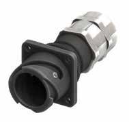
“L” can be different from the value indicated according to backshells accessories, wires size and some special insert configurations.
90 Go online for data sheets & assembly instructions. Visit www.radiall.com/vansystem and enter the part number. CVBS SHELL
ØB T K M ØD S R L N Shell size ØD +0 -0.15 ØB ±0.2 L max K ±0.2 M ±0.2 Backshell Metric Thread ØN Clamping range R ±0.1 S ±0.3 ØT ±0.2 ØT1 Through holes ØC* ±0.2 10SL 18.2 20 87 2.8 14.2 M12 3.5-7 18.2 25.4 3.1 3.4 17 14S 24.6 24 93 3.2 14.5 M16 4.5-10 23 30.2 3.1 3.4 20 16S 27.4 27 96.5 3.2 14.2 M20 7-13 24.6 32.5 3.1 3.4 23 16 27.4 27 103.5 3.2 19 M20 7-13 24.6 32.5 3.1 3.4 23 18 30.8 30 103.5 4 19 M20 7-13 27 34.9 3.1 3.4 26.5 20 34.2 32 104.5 4 19 M25 9-17 29.4 38.1 3.1 3.4 30 22 37.4 37 110.5 4 19.7 M32 11-21 31.8 41 3.1 3.4 33 24 40.9 40 112.5 4 20.6 M32 11-21 34.9 44.5 3.7 3.9 36 28 46.7 45 122.5 4 20.6 M32 11-21 39.7 50.8 3.7 3.9 42 32 53.4 52 127 4 22.2 M40 19-28 44.5 57 4.4 4.5 48.5 36 59.6 58 132 4 22.2 M40 19-28 49.2 63.5 4.4 4.5 55 40 65.5 63.2 138 4 22.2 M40 19-28 55.6 69.8 4.4 4.5 61
Dimensions in mm R ØC ØT 1 Panel
out IP67 * *
Dimension
cut
For installation with backshell mounted, consult our sales office.
CVBS - Bayonet Connector with protected mating ramps
Shell Material
Series Code Shell Type Connector Class Shell finish
internal thread
Grommet (RA..MH RA..PH Class only) Gasket
RF Insulating material
Grommet cone (RA..MH RA..PH Class only)
- Chloroprene rubber
V Fluoride rubber
S Silicone rubber
RF Fire resistant rubber
CVBS Series Code CVBS Bayonet Connector with protected mating ramps
Shell Material - Aluminum
00 Shell Type 00 Front mounting Receptacle
DA Connector Class
T Connector Modification**
DA with waterproof O-ring (IP67)
RA with waterproof O-ring and grommet (IP67)
T With plastic caps
FF Receptacle connector with threaded holes
Receptacle connector with through holes
FS Receptacle connector with countersunk holes
20-27 Insert Arrangement Size - Type
Backshell
MH12 Backshell internal thread
CR Contact Termination
Glands
S Contact Gender S Socket contacts P Pin contacts X Polarization Code** Alternate Positions
MH Provided with a Metric thread Cable Glands
PH Provided with a PG thread Cable Glands***
- Solder contacts
CR Crimp contacts
LC Less contacts
CD5 Contact Plating - Silver plating
F7 Shell finish
CD5 Gold plating
F5 Electroless nickel (*)
F7 Black epoxy varnish (*)
F16
CCF - Black passivation (*) - conductive
F26 hard anodization (*)
G Panel Gasket - Without gasket
G With waterproof panel gasket
G2 With shielded panel gasket
G3 With waterproof shielded panel gasket N Modification Code** N Consult our sales office S
91 Go online for data sheets & assembly instructions. Visit www.radiall.com/vansystem and enter the part number.
SHELL
CVBS
(*) RoHS compliance P/N Sample: RF CVBS 00DAT 20-27SX MH12 CR CD5 F7 G N RF CVBS 00 DA 20-27 S X MH12 CR CD5 F7 G N T
Backshell
Metal Cable
(**) If required *** Consult our sales office
This class is suitable to connect single wires when strain relief is not necessary and small longitudinal overall dimensions are needed. As watertightness is guaranteed by the grommet only, it is necessary to make sure the wire diameter matches the grommet sealing range.
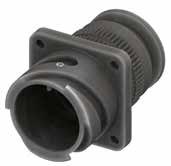
Panel cut out
* For installation with backshell mounted, consult our sales office.
Dimension “L” can be different from the value indicated according to backshells accessories, wires size and some special insert configurations. Dimensions
92 Go online for data sheets & assembly instructions. Visit www.radiall.com/vansystem and enter the part number. CVBS SHELL CVBS
N T S R L K M D ØB Shell size ØD +0 -0.15 ØB ±0.2 L K ±0.2 M ±0.2 N max cable dimension R ±0.1 S ±0.3 ØT ±0.2 ØT1 Through holes ØC* ±0.2 10SL 18.2 20 35 2.8 14.2 10 18.2 25.4 3.1 3.4 17 14S 24.6 24 35.5 3.2 14.5 13.5 23 30.2 3.1 3.4 20 16S 27.4 27 39 3.2 14.2 16.1 24.6 32.5 3.1 3.4 23 16 27.4 27 48.5 3.2 19 16.5 24.6 32.5 3.1 3.4 23 18 30.8 29.4 50 4 19 19 27 34.9 3.1 3.4 26.5 20 34.2 32 50 4 19 22.2 29.4 38.1 3.1 3.4 30 22 37.4 37 52 4 19.7 24.5 31.8 41 3.1 3.4 33 24 40.9 40 55.6 4 20.6 28 34.9 44.5 3.7 3.9 36 28 46.7 45 56 4 20.6 32.6 39.7 50.8 3.7 3.9 42 32 53.4 52 58 4 22.2 38 44.5 57 4.4 4.5 48.5 36 59.6 58 61.5 4 22.2 45 49.2 63.5 4.4 4.5 55 40 65.5 63.2 59 4 22.2 51.3 55.6 69.8 4.4 4.5 61
- Bayonet Connector with protected mating ramps Front Mounting Receptacle (00) with Backshell Class (AR - R)
in mm R ØC ØT 1
*
CVBS - Bayonet Connector with protected mating ramps
The accessories for this class are not always available in stock for all sizes; we suggest you consult our Sales Office for availability
RF Insulating material
- Chloroprene rubber
V Fluoride rubber S Silicone rubber
RF Fire resistant rubber CVBS Series Code
R Connector Class
non watertight R With O-ring and grommet
T Connector Modification** T With plastic caps
FF Receptacle connector with threaded holesReceptacle connector with through holes
FS Receptacle connector with countersunk holes 20-27 Insert Arrangement
S Contact Gender S Socket contacts P Pin contacts
X Polarization Code**
CR Contact Termination
CD5 Contact Plating
Alternate Positions
- Solder contacts
CR Crimp contacts
LC Less contacts
- Silver plating
CD5 Gold plating
F5
Electroless nickel (*)
F7 Black epoxy varnish (*)
F16
CCF - Black passivation (*) - conductive
F26 hard anodization (*) G Panel Gasket - Without gasket
G With waterproof panel gasket
G2 With shielded panel gasket
G3 With waterproof shielded panel gasket N Modification Code** N Consult our sales office S
93 Go online for data sheets & assembly instructions. Visit www.radiall.com/vansystem and enter the part number.
SHELL
ØB
CVBS
Series Code Shell Type Connector Class Shell finish
Grommet cone (R Class only) Grommet (R Class only) Gasket (R Class only) (*) RoHS compliance P/N Sample: RF CVBS 00RT 20-27SX CR CD5 F7 G N RF CVBS 00 R 20-27 S X CR CD5 F7 G N T Shell
Backshell
Material (**) If required
00
Type 00 Front mounting Receptacle
CVBS Bayonet Connector with protected mating ramps Shell Material - Aluminum
Shell
AR
Size - Type
F7 Shell finish
CVBS - Bayonet Connector with protected mating ramps
Front Mounting Receptacle (00) with Backshell Class (AG - G)
These classes of connectors are all suitable for heat shrink tubing applications.
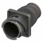
Panel cut out
* For installation with backshell mounted, consult our sales office.
Dimension “L” can be different from the value indicated according to backshells accessories, wires size and some special insert configurations.
94 Go online for data sheets & assembly instructions. Visit www.radiall.com/vansystem and enter the part number. CVBS SHELL
ØD3 L1 L2 ØD2 ØB ØD4 K M D L T S R ØD1 Shell size ØD +0 -0.15 ØB ±0.2 ØD1 ±0.2 ØD2 ±0.2 ØD3 ±0.2 ØD4 ±0.2 L L1 ±0.2 L2 ±0.2 K ±0.2 M ±0.2 R ±0.1 S ±0.3 ØT ±0.2 ØT1 Through holes ØC* ±0.2 10SL 18.2 20 17 15.5 13.3 7.9 48 11.7 3.5 2.8 14.2 18.2 25.4 3.1 3.4 17 14S 24.6 24 20.1 19.1 17 13.5 48 11.7 3.5 3.2 14.5 23 30.2 3.1 3.4 20 16S 27.4 27 23.5 23.9 21.9 13.7 48 11.7 3.5 3.2 14.2 24.6 32.5 3.1 3.4 23 16 27.4 27 23.5 23.9 21.9 16.1 60 11.5 3.5 3.2 19 24.6 32.5 3.1 3.4 23 18 30.8 30 26.5 23.9 21.9 19 65 11.5 3.5 4 19 27 34.9 3.1 3.4 26.5 20 34.2 33 30.2 29.6 26.2 22.2 65 12.4 3.5 4 19 29.4 38.1 3.1 3.4 30 22 37.4 37 33.6 29.6 26.2 22 65 12.7 3.5 4 19.7 31.8 41 3.1 3.4 33 24 40.9 40 36.1 37.8 34.5 28 65 12.7 3.5 4 20.6 34.9 44.5 3.7 3.9 36 28 46.7 45 41.4 37.8 34.5 29 65 12.7 3.5 4 20.6 39.7 50.8 3.7 3.9 42 32 53.4 52 50 47.8 43.4 35.2 70 15.2 3.5 4 22.2 44.5 57 4.4 4.5 48.5 36 59.6 57.2 56 47.7 43.4 40 75 15.2 3.5 4 22.2 49.2 63.5 4.4 4.5 55 40 65.5 63.6 62.4 57.6 52.4 48 77 15.2 3.5 4 22.2 55.6 69.8 4.4 4.5 61
in mm R ØC ØT 1
Dimensions
*
CVBS - Bayonet Connector with protected mating ramps
The accessories for this class are not always available in stock for all sizes; we suggest you consult our Sales Office for availability
RF Insulating material - Chloroprene rubber V Fluoride rubber S Silicone rubber
RF Fire resistant rubber
CVBS Series Code CVBS Bayonet Connector with protected mating ramps
Shell Material - Aluminum
00 Shell Type
AG Connector Class AG With waterproof O-ring (IP67***)
G With waterproof O-ring and grommet (IP67***)
T With plastic caps
FF Receptacle connector with threaded holes
T Connector Modification**
Receptacle connector with through holes
FS Receptacle connector with countersunk holes
CR Contact Termination
CD5 Contact Plating
F7 Shell finish
G Panel Gasket
Alternate Positions
- Solder contacts
CR Crimp contacts
LC Less contacts
- Silver plating
CD5 Gold plating
F5 Electroless nickel (*)
F7 Black epoxy varnish (*)
F16 CCF - Black passivation (*) - conductive
F26 hard anodization (*)
- Without gasket
20-27 Insert Arrangement Size - Type S Contact Gender S Socket contacts P Pin contacts X Polarization Code**
G With waterproof panel gasket
G2 With shielded panel gasket
G3 With waterproof shielded panel gasket N Modification Code** N
Consult our sales office S
95 Go online for data sheets &
Visit www.radiall.com/vansystem and enter the part number.
SHELL
assembly instructions.
CVBS
ØD3 L1 L2 ØD2 ØB ØD1 ØD4
Series Code Shell Type Connector Class Shell finish
Grommet
Grommet
Gasket
RF CVBS 00AGT 20-27SX CR CD5 F7 G N RF CVBS 00 AG 20-27 S X CR CD5 F7 G N T
Backshell
cone (G Class only)
(G Class only)
P/N Sample:
Shell Material (*) RoHS compliance (**) If required *** Protection degree: IP 67 (only in the mating area with mated connectors) according to EN 60529
00 Front mounting Receptacle
CVBS - Bayonet Connector with protected mating ramps
Front Mounting Receptacle (00) with Backshell Class (AG2 - G2)
These classes of connectors are all suitable for heat shrink tubing applications. Two piece backshell includes nut for shell tightening. Internal serration prevents backshell rotation and allows easy assembling after contacts are inserted.
cut out
* For installation with backshell mounted, consult our sales office.
96 Go online for data sheets & assembly instructions. Visit www.radiall.com/vansystem and enter the part number. CVBS SHELL
K M D L T S R ØD1 ØD3 ØB L1 L2 ØD2 ØD4 Shell size ØD +0 -0.15 ØB ±0.2 ØD1 ±0.2 ØD2 ±0.2 ØD3 ±0.2 ØD4 ±0.2 L L1 ±0.2 L2 ±0.2 K ±0.2 M ±0.2 R ±0.1 S ±0.3 ØT ±0.2 ØT1 Through holes ØC* ±0.2 10SL 18.2 22.5 17 15.5 13.3 8.6 51 11.7 3.5 2.8 14.2 18.2 25.4 3.1 3.4 17 14S 24.6 26 20.1 19.1 17 10.8 51 11.7 3.5 3.2 14.5 23 30.2 3.1 3.4 20 16S 27.4 29 23.5 23.9 21.9 14 51 11.7 3.5 3.2 14.2 24.6 32.5 3.1 3.4 23 16 27.4 29 23.5 23.9 21.9 14 62 11.5 3.5 3.2 19 24.6 32.5 3.1 3.4 23 18 30.8 33.4 26.5 23.9 21.9 14.8 63 11.5 3.5 4 19 27 34.9 3.1 3.4 26.5 20 34.2 37 30.2 29.6 26.2 19.3 63 12.4 3.5 4 19 29.4 38.1 3.1 3.4 30 22 37.4 41 33.6 29.6 26.2 22.5 63 12.7 3.5 4 19.7 31.8 41 3.1 3.4 33 24 40.9 45.9 36.1 37.8 34.5 28 64 12.7 3.5 4 20.6 34.9 44.5 3.7 3.9 36 28 46.7 51 41.4 37.8 34.5 28 66 12.7 3.5 4 20.6 39.7 50.8 3.7 3.9 42 32 53.4 58 50 47.8 43.4 34.8 67 15.2 3.5 4 22.2 44.5 57 4.4 4.5 48.5 36 59.6 60.5 56 47.7 43.4 38.7 67 15.2 3.5 4 22.2 49.2 63.5 4.4 4.5 55 40 65.5 69 62.4 57.6 52.4 48.2 68 15.2 3.5 4 22.2 55.6 69.8 4.4 4.5 61 Dimension “L” can be different from the value indicated
size
insert configurations. Dimensions in mm R ØC ØT 1 Panel
*
according to backshells accessories, wires
and some special
CVBS - Bayonet Connector with protected mating ramps
Shell Material
Series Code Shell Type Connector Class Shell finish
The accessories for this class are not always available in stock for all sizes; we suggest you consult our Sales Office for availability
RF Insulating material - Chloroprene rubber V Fluoride rubber S Silicone rubber RF Fire resistant rubber
with protected mating ramps Shell Material - Aluminum 00 Shell
AG2 With waterproof O-ring (IP67***)
G2 Connector Class
T Connector Modification**
G2 With waterproof O-ring and grommet (IP67***)#
T With plastic caps
FF Receptacle connector with threaded holes
Receptacle connector with through holes
FS Receptacle connector with countersunk holes
Polarization Code** Alternate Positions CR Contact Termination
- Solder contacts
CR Crimp contacts
LC Less contacts
CD5 Contact Plating - Silver plating
F7 Shell finish
CD5 Gold plating
F5 Electroless nickel (*)
F7 Black epoxy varnish (*)
F16
20-27 Insert Arrangement Size - Type S Contact Gender S Socket contacts P Pin contacts
CCF - Black passivation (*) - conductive
F26 hard anodization (*)
G Panel Gasket - Without gasket
G With waterproof panel gasket
G2 With shielded panel gasket
G3 With waterproof shielded panel gasket
Modification Code**
Protection degree: IP 67 (only in the mating area with mated connectors) according to EN 60529
Consult our sales office
RoHS compliance (**) If required
97 Go online for data sheets & assembly instructions. Visit www.radiall.com/vansystem and enter the part number.
SHELL
CVBS
G2
Two piece
Grommet
Gasket
RF CVBS 00G2T 20-27SX CR CD5 F7 G N RF CVBS 00 G2 20-27 S X CR CD5 F7 G N T
(*)
backshell Grommet cone (G2 Class only)
(G2 Class only)
P/N Sample:
***
(#) In some sizes the grommet cone is not needed
00
CVBS Series Code CVBS Bayonet Connector
Type
Front mounting Receptacle
X
N
N
S
CVBS - Bayonet Connector with protected mating ramps
Front Mounting Receptacle (00) with Backshell Class (ASB1 - SB1)
Backshell for multicore jacketed shielded cables, provided with MS 3057…C type Cable-Clamp. (for jacketed cable) Also available versions for over/under dimensioned cables.
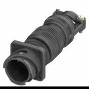
Dimension “L” can be different from the value indicated according to backshells accessories, wires size and some special insert configurations.
98 Go online for data sheets & assembly instructions. Visit www.radiall.com/vansystem and enter the part number. CVBS SHELL
K M Ø D L ØB A Ø F T S R Shell size ØD +0 -0.15 ØB ±0.2 K ±0.2 L M ±0.2 A ±0.2 ØF cable dimension R ±0.1 S ±0.3 ØT ±0.2 ØT1 Through holes ØC* ±0.2 Min Max 10SL 18.2 20 2.8 99 14.2 23 2.4 7.9 18.2 25.4 3.1 3.4 17 14S 24.6 24 3.2 99 14.5 26 5.8 11.2 23 30.2 3.1 3.4 20 16S 27.4 27 3.2 100 14.2 28.5 8 13.5 24.6 32.5 3.1 3.4 23 16 27.4 27 3.2 118 19 28.5 8 13.5 24.6 32.5 3.1 3.4 23 18 30.8 32 4 124 19 32 9.6 15.9 27 34.9 3.1 3.4 26.5 20 34.2 35 4 124 19 37.5 11.3 19 29.4 38.1 3.1 3.4 30 22 37.4 37 4 124 19.7 37.5 11.3 19 31.8 41 3.1 3.4 33 24 40.9 42 4 135 20.6 43.5 15.5 23.8 34.9 44.5 3.7 3.9 36 28 46.7 45 4 138 20.6 43.5 15.5 23.8 39.7 50.8 3.7 3.9 42 32 53.4 50 4 146 22.2 54 23.4 31.8 44.5 57 4.4 4.5 48.5 36 59.6 58 4 150 22.2 58 25.4 35 49.2 63.5 4.4 4.5 55 40 65.5 63.8 4 154 22.2 63.5 30 41.3 55.6 69.8 4.4 4.5 61
Dimensions in mm R ØC ØT 1
IP67 * *
Panel cut out
For installation with backshell mounted, consult our sales office.
CVBS - Bayonet Connector with protected mating ramps
with waterproof
ASB1 Connector
(IP67) SB1 with waterproof O-ring and grommet (IP67)# T Connector Modification**
With plastic caps FF Receptacle connector with threaded holesReceptacle connector with through holes FS Receptacle connector with countersunk holes
CD5 Contact Plating
Solder contacts CR Crimp contacts
LC Less contacts
- Silver plating
CD5 Gold plating
F5 Electroless nickel (*)
F7 Black epoxy varnish (*)
F16 CCF - Black passivation (*) - conductive
F26 hard anodization (*)
- Without gasket G With waterproof panel gasket
G2 With shielded panel gasket
G3 With waterproof shielded panel gasket
99 Go online for data sheets & assembly instructions. Visit www.radiall.com/vansystem and enter the part number.
SHELL
CVBS
Backshell Grommet
Gasket (*) RoHS compliance
Sample: RF CVBS 00SB1T 20-27SX CR CD5 F7 G N
MS3057...C Series Code Shell Type Connector Class Shell finish RF CVBS 00 ASB1 20-27 S X CR CD5 F7 G N T Shell Material (**)
required
all
we suggest you consult our Sales Office for availability Shielding Ring Backshell Gasket (#)
sizes the grommet
is not needed
V
S
CVBS Series Code CVBS Bayonet Connector
mating ramps Shell Material - Aluminum 00 Shell Type 00 Front mounting Receptacle
Size
Type S
X
cone (SB1 Class only) Grommet (SB1 Class only)
P/N
Cable-Clamp
If
The accessories for this class are not always available in stock for
sizes;
In some
cone
RF Insulating material - Chloroprene rubber
Fluoride rubber
Silicone rubber RF Fire resistant rubber
with protected
Class ASB1
O-ring
T
20-27 Insert Arrangement
-
Contact Gender S Socket contacts P Pin contacts
Polarization Code** Alternate Positions CR Contact Termination -
F7 Shell finish
G Panel Gasket
N
N
S
Modification Code**
Consult our sales office
CVBS - Bayonet Connector with protected mating ramps
Front Mounting Receptacle (00) with Backshell Class (AGV - GV)
These classes of connectors are provided with backshell for shield hose and heat shrink tubing termination. It comes complete with conical protection spring, also suitable for thin shield braid.
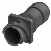
Panel cut out
* For installation with backshell mounted, consult our sales office.
“L” can be different from the value indicated according to backshells accessories, wires size and some special insert configurations.
100 Go online for data sheets & assembly instructions. Visit www.radiall.com/vansystem and enter the part number. CVBS SHELL
K M D L ØB T S R Ø D1 Ø D2 ØD3 L2 3.5 Shell size ØD +0 -0.15 ØB ±0.2 ØD1 ±0.2 ØD2 ±0.2 ØD3 ±0.2 L L2 ±0.2 K ±0.2 M ±0.2 R ±0.1 S ±0.3 ØT ±0.2 ØT1 Through holes ØC* ±0.2 10SL 18.2 20 8.6 18.5 16.3 65 18 2.8 14.2 18.2 25.4 3.1 3.4 17 14S 24.6 24 10.6 22 20 65 17.6 3.2 14.5 23 30.2 3.1 3.4 20 16S 27.4 27 10.4 25 23 65 20.7 3.2 14.2 24.6 32.5 3.1 3.4 23 16 27.4 27 13.5 25 23 74 20.8 3.2 19 24.6 32.5 3.1 3.4 23 18 30.8 30 14.5 28 24.5 75 20.8 4 19 27 34.9 3.1 3.4 26.5 20 34.2 32 18.4 32 28.5 75 20.8 4 19 29.4 38.1 3.1 3.4 30 22 37.4 37 20.7 34 30.5 75 20.8 4 19.7 31.8 41 3.1 3.4 33 24 40.9 40 24.6 38.5 34.5 81 20.7 4 20.6 34.9 44.5 3.7 3.9 36 28 46.7 46 25 40 36 81 21.8 4 20.6 39.7 50.8 3.7 3.9 42 32 53.4 52 33.3 48 44 83 20.7 4 22.2 44.5 57 4.4 4.5 48.5 36 59.6 58 38.5 55 51 83 20.7 4 22.2 49.2 63.5 4.4 4.5 55 40 65.5 63.8 46 62 58 83 21.8 4 22.2 55.6 69.8 4.4 4.5 61
Dimensions in mm R ØC ØT 1
*
Dimension
CVBS - Bayonet Connector with protected mating ramps
RF Insulating material - Chloroprene rubber
resistant rubber CVBS
GV Connector Class AGV With waterproof O-ring (IP67***) GV with waterproof O-ring and grommet (IP67***) T Connector Modification** T With plastic caps
FF Receptacle connector with threaded holesReceptacle connector with through holes
FS Receptacle connector with countersunk holes 20-27 Insert Arrangement
CR Contact Termination
CD5 Contact Plating
contacts
Alternate Positions
- Solder contacts
CR Crimp contacts
LC Less contacts
- Silver plating
CD5 Gold plating F7 Shell finish
F5
Electroless nickel (*)
F7 Black epoxy varnish (*)
F16 CCF - Black passivation (*) - conductive
F26 hard anodization (*) G Panel Gasket - Without gasket
G With waterproof panel gasket
G2 With shielded panel gasket
G3 With waterproof shielded panel gasket N Modification Code**
101 Go online for data sheets & assembly instructions. Visit www.radiall.com/vansystem and enter the part number.
SHELL Series
Shell Type Connector Class Shell finish
CVBS
Code
suggest you consult our Sales Office for availability P/N Sample: RF CVBS 00GVT 20-27SX CR CD5 F7 G N RF CVBS 00 GV 20-27 S X CR CD5 F7 G N T Shell Material (*) RoHS compliance (**) If required *** Protection degree: IP 67 (only in the mating area with mated connectors) according to EN 60529 GV Backshell Gasket Rear Nut Conical Ring Grommet cone (GV Class only) Grommet (GV Class only)
The accessories for this class are not always available in stock for all sizes; we
Series Code CVBS Bayonet
Shell Material - Aluminum 00 Shell Type 00 Front mounting Receptacle
V Fluoride rubber S Silicone rubber RF Fire
Connector with protected mating ramps
Size - Type S Contact Gender S Socket
P Pin contacts X Polarization Code**
S
N Consult our sales office
- Bayonet Connector with protected mating ramps Front Mounting Receptacle (00) with Backshell Class (SB)
These classes of connectors are provided with backshell for shield hose and heat shrink tubing termination. It comes complete with conical protection spring, also suitable for thin shield braid. Two piece backshell includes nut for shell tightening. Internal serration prevents backshell rotation and allows easy assembling after contacts are inserted.
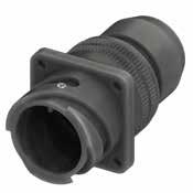
For installation with backshell mounted, consult our sales office.
102 Go online for data sheets & assembly instructions. Visit www.radiall.com/vansystem and enter the part number. CVBS SHELL
K M D L ØB T S R Ø D1 Ø D2 ØD3 L2 3.5 Shell size ØD +0 -0.15 ØB ±0.2 ØD1 ±0.2 ØD2 ±0.2 ØD3 ±0.2 L L2 ±0.2 K ±0.2 M ±0.2 R ±0.1 S ±0.3 ØT ±0.2 ØT1 Through holes ØC* ±0.2 10SL 18.2 22.5 8.6 18.5 16.3 60 18 2.8 14.2 18.2 25.4 3.1 3.4 17 14S 24.6 26.1 10.6 22 20 60 17.6 3.2 14.5 23 30.2 3.1 3.4 20 16S 27.4 29 10.4 25 23 60 20.7 3.2 14.2 24.6 32.5 3.1 3.4 23 16 27.4 29 13.5 25 23 65 20.8 3.2 19 24.6 32.5 3.1 3.4 23 18 30.8 33.5 14.5 28 24.5 69 20.8 4 19 27 34.9 3.1 3.4 26.5 20 34.2 37 18.4 32 28.5 70 20.8 4 19 29.4 38.1 3.1 3.4 30 22 37.4 41 20.7 34 30.5 70 20.8 4 19.7 31.8 41 3.1 3.4 33 24 40.9 46 24.6 38.5 34.5 73 20.7 4 20.6 34.9 44.5 3.7 3.9 36 28 46.7 51 25 40 36 74 21.8 4 20.6 39.7 50.8 3.7 3.9 42 32 53.4 58 33.3 48 44 75 20.7 4 22.2 44.5 57 4.4 4.5 48.5 36 59.6 61 38.5 55 51 75 20.7 4 22.2 49.2 63.5 4.4 4.5 55 40 65.5 69 46 62 58 75 21.8 4 22.2 55.6 69.8 4.4 4.5 61 Dimension
Dimensions in mm R ØC ØT 1 Panel
out * *
CVBS
“L” can be different from the value indicated according to backshells accessories, wires size and some special insert configurations.
cut
CVBS - Bayonet Connector with protected mating ramps
RF Insulating material - Chloroprene rubber V Fluoride rubber S Silicone rubber
RF Fire resistant rubber
SB Connector Class
T Connector Modification**
With waterproof O-ring and grommet (IP67***)#
T With plastic caps
FF Receptacle connector with threaded holesReceptacle connector with through holes
FS Receptacle connector with countersunk holes
CR Contact Termination
- Solder contacts
CR Crimp contacts
LC Less contacts
CD5 Contact Plating - Silver plating
F7 Shell finish
CD5 Gold plating
F5 Electroless nickel (*)
F7 Black epoxy varnish (*)
F16
20-27 Insert Arrangement Size - Type S Contact Gender S Socket contacts P Pin contacts X Polarization Code** Alternate Positions
CCF - Black passivation (*) - conductive
F26 hard anodization (*)
G Panel Gasket - Without gasket
G With waterproof panel gasket
G2 With shielded panel gasket
G3 With waterproof shielded panel gasket N Modification Code** N
Consult our sales office S
103 Go online for data sheets & assembly instructions. Visit www.radiall.com/vansystem and enter the part number.
SHELL
Shell
CVBS
Series Code Shell Type Connector Class
finish
RF CVBS 00SBT 20-27SX CR CD5 F7 G N RF CVBS 00 SB 20-27 S X CR CD5 F7 G N T Shell Material (*)
compliance
required *** Protection degree: IP 67
mating area
mated connectors) according to EN 60529 GV Two piece backshell Gasket Rear Nut Conical Ring Grommet cone Grommet (#)
needed
The accessories for this class are not always available in stock for all sizes; we suggest you consult our Sales Office for availability P/N Sample:
RoHS
(**) If
(only in the
with
In some sizes the grommet cone is not
Shell Material - Aluminum
Type 00
CVBS Series Code CVBS Bayonet Connector with protected mating ramps
00 Shell
Front mounting Receptacle
SB
CVBS - Bayonet Connector with protected mating ramps
Front Mounting Receptacle (020) without Accessories (To be purchased separately)
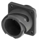
104 Go online for data sheets & assembly instructions. Visit www.radiall.com/vansystem and enter the part number. CVBS SHELL
Shell size ØD +0 -0.15 L K ±0.2 M ±0.2 ØN Thread in inches R ±0.1 S ±0.3 ØT ±0.2 ØT1 Through holes ØC ±0.2 10SL 18.2 24.6 2.8 14.2 5/8”-24 UNEF 18.2 25.4 3.1 3.4 17 14S 24.6 24.6 3.2 14.5 3/4”-20 UNEF 23 30.2 3.1 3.4 20 16S 27.4 24.6 3.2 14.2 7/8”-20 UNEF 24.6 32.5 3.1 3.4 23 16 27.4 34.1 3.2 19 7/8”-20 UNEF 24.6 32.5 3.1 3.4 23 18 30.8 34.1 4 19 1”-20 UNEF 27 34.9 3.1 3.4 26.5 20 34.2 34.3 4 19 1” 1/8-18 UNEF 29.4 38.1 3.1 3.4 30 22 37.4 34.3 4 19.7 1” 1/4-18 UNEF 31.8 41 3.1 3.4 33 24 40.9 35.8 4 20.6 1” 3/8-18 UNEF 34.9 44.5 3.7 3.9 36 28 46.7 35.8 4 20.6 1” 5/8-18 UNEF 39.7 50.8 3.7 3.9 42 32 53.4 37.6 4 22.2 1” 7/8-16 UN 44.5 57 4.4 4.5 48.5 36 59.6 37.6 4 22.2 2” 1/16-16 UNS 49.2 63.5 4.4 4.5 55 40 65.5 37.6 4 22.2 2” 5/16-16 UNS 55.6 69.8 4.4 4.5 61 Dimension “L” can be different from the value indicated according to wires size and some special insert configurations. Dimensions in mm R ØC ØT 1 Panel cut out T S R K M L ØD ØN
CVBS - Bayonet Connector with protected mating ramps
RF Insulating material
T Connector Modification** T With plastic caps
FF Receptacle connector with threaded holes - Receptacle connector with through holes
FS Receptacle connector with countersunk holes
20-27 Insert Arrangement Size - Type
Socket contacts
S Contact Gender
Pin contacts X Polarization Code** Alternate Positions CR Contact Termination
Solder contacts
Crimp contacts LC Less contacts
CD5 Contact Plating
F7 Shell finish
Silver plating CD5 Gold plating
F5 Electroless nickel (*)
F7 Black epoxy varnish (*)
F16
CCF - Black passivation (*) - conductive
F26 hard anodization (*)
G Panel Gasket - Without gasket G With waterproof panel gasket
G2 With shielded panel gasket
G3 With waterproof shielded panel gasket
N Modification Code**
105 Go online for data sheets & assembly instructions. Visit www.radiall.com/vansystem and enter the part number.
Shell
Shell finish
CVBS SHELL Series Code
Type
(*)
RF CVBS 020T 20-27SX CR CD5 F7 G N RF CVBS 020 20-27 S X CR CD5 F7 G N T
required
-
V
CVBS Series Code CVBS Bayonet Connector with protected mating ramps
-
RoHS compliance P/N Sample:
Shell Material (**) If
Chloroprene rubber
Fluoride rubber S Silicone rubber RF Fire resistant rubber
Shell Material
Aluminum 020 Shell Type 020 Front mounting Receptacle
S
P
-
CR
-
N
S
Consult our sales office
CVBS - Bayonet Connector with protected mating ramps
Front Mounting Receptacle (02 - 02A - 02R) unable to Accept Rear Accessories
106 Go online for data sheets & assembly instructions. Visit www.radiall.com/vansystem and enter the part number. CVBS SHELL
T S R K M L ØD ØN Shell size ØD +0 -0.15 L K ±0.2 M ±0.2 ØN Max R ±0.1 S ±0.3 ØT ±0.2 ØT1 Through holes ØC ±0.2 10SL 18.2 24.6 2.8 14.2 16.1 18.2 25.4 3.1 3.4 17 14S 24.6 24.6 3.2 14.5 19.2 23 30.2 3.1 3.4 20 16S 27.4 24.6 3.2 14.2 22.5 24.6 32.5 3.1 3.4 23 16 27.4 34.1 3.2 19 22.4 24.6 32.5 3.1 3.4 23 18 30.8 34.1 4 19 25.6 27 34.9 3.1 3.4 26.5 20 34.2 34.3 4 19 28.8 29.4 38.1 3.1 3.4 30 22 37.4 34.3 4 19.7 32.2 31.8 41 3.1 3.4 33 24 40.9 35.8 4 20.6 35.3 34.9 44.5 3.7 3.9 36 28 46.7 35.8 4 20.6 41.5 39.7 50.8 3.7 3.9 42 32 53.4 37.6 4 22.2 47.8 44.5 57 4.4 4.5 48.5 36 59.6 37.6 4 22.2 52.6 49.2 63.5 4.4 4.5 55 40 65.5 37.6 4 22.2 59.2 55.6 69.8 4.4 4.5 61 Dimension
can
different
value
wires size
some special insert configurations. Dimensions in mm R ØC ØT 1
“L”
be
from the
indicated according to
and
Panel cut out
CVBS - Bayonet Connector with protected mating ramps
Connector Modification**
Front mounting receptacle connector unable to accept rear accessories (standard version)
Front mounting receptacle connector non enviromental (equivalent MS3102A..B bayonet version)
Front mounting receptacle connector enviromental seal (unable to accept rear accessories)
Receptacle connector with threaded holes
Receptacle connector with through holes
Receptacle connector with countersunk holes
CR Contact Termination
Solder contacts
contacts
contacts
contacts CD5 Contact Plating
plating
107 Go online for data sheets & assembly instructions. Visit www.radiall.com/vansystem and enter the part number.
SHELL Series Code Shell Type Shell finish
CVBS
(*) RoHS compliance P/N Sample: RF CVBS 02T 20-27SX CR CD5 F7 G N RF CVBS 02 20-27 S X CR CD5 F7 G N T Shell Material (**) If required RF
- Chloroprene rubber V Fluoride rubber S Silicone rubber RF Fire resistant rubber CVBS Series Code CVBS Bayonet Connector with protected mating ramps Shell Material - Aluminum 02 Shell Type 02
02A
02R
T
T
FF
-
FS
20-27
Size - Type S Contact Gender S Socket contacts P Pin contacts X
Code** Alternate Positions
-
CR Crimp
LC Less
DS PCB
-
Electroless
F7 Black
F16 CCF
F26 hard
-
G With waterproof
G2 With
G3 With
N Modification Code** N Consult our sales office S
Insulating material
With plastic caps
Insert Arrangement
Polarization
Silver
CD5 Gold plating F7 Shell finish F5
nickel (*)
epoxy varnish (*)
- Black passivation (*) - conductive
anodization (*) G Panel Gasket
Without gasket
panel gasket
shielded panel gasket
waterproof shielded panel gasket
CVBS - Bayonet Connector with protected mating ramps
Rear Mounting Receptacle (030) without Accessories (To be purchased separately)
108 Go online for data sheets & assembly instructions. Visit www.radiall.com/vansystem and enter the part number. SHELL
value
wires
some special insert
Dimensions in mm R ØC ØT 1 Panel
out T S R P K M L ØD ØN Shell size ØD +0 -0.15 L K ±0.2 M ±0.2 N Thread in inches R ±0.1 S ±0.3 ØT ±0.2 ØT1 Threaded holes ØC ±0.2 P Panel Thickness Max 10SL 18.2 30 2.8 18.2 5/8”-24 UNEF 18.2 25.4 M4 4.5 19.1 6 14S 24.6 30 3.2 18.6 3/4”-20 UNEF 23 30.2 M4 4.5 25.5 7.2 16S 27.4 30 3.2 18.6 7/8”-20 UNEF 24.6 32.5 M4 4.5 28.3 7.2 16 27.4 38.8 3.2 23.05 7/8”-20 UNEF 24.6 32.5 M4 4.5 28.3 5.35 18 30.8 38.5 4 23.4 1”-20 UNEF 27 34.9 M4 4.5 31.7 7.25 20 34.2 39.1 4 23.4 1” 1/8-18 UNEF 29.4 38.1 M4 4.5 35 7.3 22 37.4 39.3 4 23.4 1” 1/4-18 UNEF 31.8 41 M4 4.5 38.3 7.3 24 40.9 38.8 4 23.4 1” 3/8-18 UNEF 34.9 44.5 M4 4.5 41.8 6.85 28 46.7 39.1 4 24.4 1” 5/8-18 UNEF 39.7 50.8 M5 5.5 47.6 7.8 32 53.4 38.4 4 24.4 1” 7/8-16 UN 44.5 57 M5 5.5 54.3 7.5 36 59.6 39.9 4 24.4 2” 1/16-16 UNS 49.2 63.5 M5 5.5 60.5 7.5 40 65.5 38.5 4 24.4 2” 5/16-16 UNS 55.6 69.8 M5 5.5 66.4 7.5
Dimension “L” can be different from the
indicated according to
size and
configurations.
cut
CVBS - Bayonet Connector with protected mating ramps
RF Insulating material
T Connector Modification**
20-27 Insert Arrangement
rubber RF Fire resistant rubber
Rear mounting Receptacle
T With plastic caps - Receptacle connector with threaded holes
FP Receptacle connector with through holes
FS Receptacle connector with countersunk holes
Size - Type
S Contact Gender S Socket contacts
Polarization Code** Alternate Positions
CR Contact Termination
Solder contacts CR Crimp contacts LC Less contacts
CD5 Contact Plating - Silver plating
CD5 Gold plating
F5 Electroless nickel (*)
F7 Black epoxy varnish (*)
F7 Shell finish
F16
CCF - Black passivation (*) - conductive
F26 hard anodization (*)
G Panel Gasket - Without gasket G With waterproof panel gasket
G2 With shielded panel gasket
G3 With waterproof shielded panel gasket
N Modification Code**
109 Go online for data sheets & assembly instructions. Visit www.radiall.com/vansystem and enter the part number.
Shell
SHELL Series Code Shell Type
finish
(*)
Sample: RF CVBS 020T 20-27SX CR CD5 F7 G N RF CVBS 030 20-27 S X CR CD5 F7 G N T
If required
RoHS compliance P/N
Shell Material (**)
CVBS Series Code CVBS Bayonet Connector with protected mating ramps
-
030
030
- Chloroprene rubber V Fluoride rubber S Silicone
Shell Material
Aluminum
Shell Type
P Pin contacts X
-
N
Consult our sales office S
CVBS - Bayonet Connector with protected mating ramps
Rear Mounting Receptacle (030) with Backshell Class (A - DA - RA)
Connector with backshell provided with an external thread suitable for MS3057…A or C type Cable-Clamps (to be ordered separately).
cut out
Dimension “L” can be different from the value indicated according to backshells accessories, wires size and some special insert configurations.
110 Go online for data sheets & assembly instructions. Visit www.radiall.com/vansystem and enter the part number. CVBS SHELL
ØB N T S R K M ØD L P Shell size ØD +0 -0.15 ØB ±0.2 L M ±0.2 K ±0.2 N Backshell Thread in inches R ±0.1 S ±0.3 ØT ØT1 ØC ±0.2 P Panel Thickness Max 10SL 18.2 20 46 18.2 2.8 5/8”-24 UNEF 18.2 25.4 M4 4.5 19.1 6 14S 24.6 24 47.5 18.6 3.2 3/4”-20 UNEF 23 30.2 M4 4.5 25.5 7.2 16S 27.4 27 47.5 18.6 3.2 7/8”-20 UNEF 24.6 32.5 M4 4.5 28.3 7.2 16 27.4 27 54.5 23.05 3.2 7/8”-20 UNEF 24.6 32.5 M4 4.5 28.3 5.35 18 30.8 30 55.5 23.4 4 1”-20 UNEF 27 34.9 M4 4.5 31.7 7.25 20 34.2 32 55.5 23.4 4 1” 3/16-18 UNEF 29.4 38.1 M4 4.5 35 7.3 22 37.4 37 58 23.4 4 1” 3/16-18 UNEF 31.8 41 M4 4.5 38.3 7.3 24 40.9 40 58 23.4 4 1” 7/16-18 UNEF 34.9 44.5 M4 4.5 41.8 6.85 28 46.7 45 65 24.4 4 1” 7/16-18 UNEF 39.7 50.8 M5 5.5 47.6 7.8 32 53.4 52 65 24.4 4 1” 3/4-18 UNS 44.5 57 M5 5.5 54.3 7.5 36 59.6 58 65 24.4 4 2”-18 UNS 49.2 63.5 M5 5.5 60.5 7.5 40 65.5 63.2 65 24.4 4 2”1/4-16 UN 55.6 69.8 M5 5.5 66.4 7.5
mm R ØC ØT 1
Dimensions in
Panel
CVBS - Bayonet Connector with protected mating ramps
RF Insulating material
- Chloroprene rubber
V Fluoride rubber
S Silicone rubber
RF Fire resistant rubber CVBS Series Code CVBS Bayonet Connector with protected mating ramps Shell Material - Aluminum
030 Shell Type 030 Rear mounting Receptacle
A non watertight
DA Connector Class
DA with waterproof O-ring (IP67***)
RA with waterproof O-ring and grommet (IP67***)
T With plastic caps
Receptacle connector with threaded holes
S Contact Gender
X Polarization Code**
CR Contact Termination
CD5 Contact Plating
F7 Shell finish
S Socket contacts
P Pin contacts
Alternate Positions
- Solder contacts
CR Crimp contacts
LC Less contacts
- Silver plating
CD5 Gold plating
F5 Electroless nickel (*)
F7 Black epoxy varnish (*)
F16
T Connector Modification**
FP Receptacle connector with through holes
FS Receptacle connector with countersunk holes
20-27 Insert Arrangement Size - Type
G Panel Gasket
CCF - Black passivation (*) - conductive
F26 hard anodization (*)
- Without gasket
G With waterproof panel gasket
G2 With shielded panel gasket
G3 With waterproof shielded panel gasket
N Modification Code** N
Consult our sales office S
Protection degree: IP 67 (only in the mating area with mated connectors) according to EN 60529
RoHS compliance (**) If required
111 Go online for data sheets & assembly instructions. Visit www.radiall.com/vansystem and enter the part number.
SHELL
CVBS
Shell
ØB N
Series Code Shell Type Connector Class
finish
Backshell Grommet cone (RA Class only) Grommet (RA Class only) Gasket (DA-RA Class only) P/N Sample: RF CVBS 030DAT 20-27SX CR CD5 F7 G N RF CVBS 030 DA 20-27 S X CR CD5 F7 G N T
(*)
Shell Material
***
CVBS - Bayonet Connector with protected mating ramps
Rear Mounting Receptacle (030) with Backshell Class (AF - F)
Connector provided with backshell, MS3057...A type Cable-Clamp and bushing MS3420... (for single wire)
112 Go online for data sheets & assembly instructions. Visit www.radiall.com/vansystem and enter the part number. CVBS SHELL
A F Ø T S R ØB K M ØD L P Shell size ØD +0 -0.15 ØB ±0.2 L M ±0.2 K ±0.2 A max ØF cable max dimension R ±0.1 S ±0.3 ØT ØT1 ØC ±0.2 P Panel Thickness Max 10SL 18.2 20 56 18.2 2.8 22.5 5.6 18.2 25.4 M4 4.5 19.1 6 14S 24.6 24 59.5 18.6 3.2 28 7.9 23 30.2 M4 4.5 25.5 7.2 16S 27.4 27 61 18.6 3.2 30 11 24.6 32.5 M4 4.5 28.3 7.2 16 27.4 27 68 23.05 3.2 30 11 24.6 32.5 M4 4.5 28.3 5.35 18 30.8 30 71 23.4 4 31.7 14.2 27 34.9 M4 4.5 31.7 7.25 20 34.2 32 71 23.4 4 37.5 15.8 29.4 38.1 M4 4.5 35 7.3 22 37.4 37 73.5 23.4 4 37.5 15.8 31.8 41 M4 4.5 38.3 7.3 24 40.9 40 73.5 23.4 4 43.5 19 34.9 44.5 M4 4.5 41.8 6.85 28 46.7 45 80.5 24.4 4 43.5 19 39.7 50.8 M5 5.5 47.6 7.8 32 53.4 52 80.5 24.4 4 51.7 23.8 44.5 57 M5 5.5 54.3 7.5 36 59.6 58 81 24.4 4 58.5 31.7 49.2 63.5 M5 5.5 60.5 7.5 40 65.5 63.2 94 24.4 4 68.5 34.9 55.6 69.8 M5 5.5 66.4 7.5 Dimension
different
value
according to backshells accessories, wires size and some special insert configurations. Dimensions in mm R ØC ØT 1
“L” can be
from the
indicated
IP54
Panel cut out
CVBS - Bayonet Connector with protected mating ramps
Grommet cone (F Class only) Grommet (F Class only) Gasket
RF Insulating material
- Chloroprene rubber
V Fluoride rubber
S Silicone rubber
RF Fire resistant rubber
CVBS Series Code CVBS Bayonet Connector with protected mating ramps
Shell Material - Aluminum
030 Shell Type 030 Rear mounting Receptacle
AF Connector Class
X Polarization Code**
CR Contact Termination
CD5 Contact Plating
F with waterproof O-ring and grommet (IP54)
AF with waterproof O-ring (IP54)
T With plastic caps
Receptacle connector with threaded holes
T Connector Modification**
FP Receptacle connector with through holes
FS Receptacle connector with countersunk holes
G Panel Gasket
P Pin contacts
Alternate Positions
- Solder contacts
CR Crimp contacts
LC Less contacts
- Silver plating
CD5 Gold plating
F5 Electroless nickel (*)
F7 Black epoxy varnish (*)
F16
20-27 Insert Arrangement Size - Type S Contact Gender S Socket contacts
CCF - Black passivation (*) - conductive
F26 hard anodization (*)
- Without gasket
G With waterproof panel gasket
G2 With shielded panel gasket
G3 With waterproof shielded panel gasket
N Modification Code** N
Consult our sales office S
113 Go online for data sheets & assembly instructions. Visit www.radiall.com/vansystem and enter the part number.
SHELL
CVBS
(*) RoHS compliance
RF CVBS 030AFT 20-27SX CR CD5 F7 G N H A F Ø ØB ØB A F Ø Cable-Clamp MS3057...A bushing MS3420
Shell finish RF CVBS 030 AF 20-27 S X CR CD5 F7 G N T Shell Material
Backshell
P/N Sample:
Series Code Shell Type Connector Class
(**) If required
F7 Shell finish
CVBS - Bayonet Connector with protected mating ramps
Rear Mounting Receptacle (030) with Backshell Class (AC - ACF)
Connector provided with backshell, MS3057...C type Cable-Clamp (for jacketed cable)
“L” can be different from the value indicated according to backshells accessories, wires size and some special insert configurations.
114 Go online for data sheets & assembly instructions. Visit www.radiall.com/vansystem and enter the part number. CVBS SHELL
K M ØD L P A Ø F T S R Shell size ØD +0 -0.15 ØB ±0.2 L K ±0.2 M ±0.2 A ±0.2 ØF cable dimension R ±0.1 S ±0.3 ØT ØT1 ØC ±0.2 P Panel Thickness Max Min Max 10SL 18.2 20 70 2.8 18.2 23 2.4 7.9 18.2 25.4 M4 4.5 19.1 6 14S 24.6 24 71.5 3.2 18.6 26 5.8 11.2 23 30.2 M4 4.5 25.5 7.2 16S 27.4 27 72.5 3.2 18.6 28.5 8 13.5 24.6 32.5 M4 4.5 28.3 7.2 16 27.4 27 79.5 3.2 23.05 28.5 8 13.5 24.6 32.5 M4 4.5 28.3 5.35 18 30.8 30 83 4 23.4 32 9.6 15.9 27 34.9 M4 4.5 31.7 7.25 20 34.2 32 83 4 23.4 37.5 11.3 19 29.4 38.1 M4 4.5 35 7.3 22 37.4 37 84.5 4 23.4 37.5 11.3 19 31.8 41 M4 4.5 38.3 7.3 24 40.9 40 91.5 4 23.4 43.5 15.5 23.8 34.9 44.5 M4 4.5 41.8 6.85 28 46.7 45 98.5 4 24.4 43.5 15.5 23.8 39.7 50.8 M5 5.5 47.6 7.8 32 53.4 52 103 4 24.4 54 23.4 31.8 44.5 57 M5 5.5 54.3 7.5 36 59.6 58 107.5 4 24.4 58 25.4 35 49.2 63.5 M5 5.5 60.5 7.5 40 65.5 63.2 109 4 24.4 63.5 30 41.3 55.6 69.8 M5 5.5 66.4 7.5
Dimensions
mm R ØC ØT 1 Panel cut out IP67
Dimension
in
CVBS - Bayonet Connector with protected mating ramps
Series Code Shell Type Connector Class
Grommet cone (ACF Class only)
Grommet (ACF Class only) Gasket
Backshell
RF Insulating material - Chloroprene rubber
V Fluoride rubber
S Silicone rubber
RF Fire resistant rubber
CVBS Series Code CVBS Bayonet Connector with protected mating ramps
Shell Material - Aluminum
030 Shell Type 030 Rear mounting Receptacle
AC Connector Class
T Connector Modification**
ACF with waterproof O-ring and grommet (IP67)
AC with waterproof O-ring (IP67)
T With plastic caps
Receptacle connector with threaded holes
FP Receptacle connector with through holes
FS Receptacle connector with countersunk holes
X Polarization Code** Alternate Positions
CR Contact Termination
CD5 Contact Plating
G Panel Gasket
- Solder contacts
CR Crimp contacts
LC Less contacts
- Silver plating
CD5 Gold plating F7 Shell finish
F5 Electroless nickel (*)
F7 Black epoxy varnish (*)
F16
20-27 Insert Arrangement Size - Type S Contact Gender S Socket contacts P Pin contacts
CCF - Black passivation (*) - conductive
F26 hard anodization (*)
- Without gasket
G With waterproof panel gasket
G2 With shielded panel gasket
G3 With waterproof shielded panel gasket
N Modification Code** N
Consult our sales office S
P/N Sample:
115 Go online for data sheets & assembly instructions. Visit www.radiall.com/vansystem and enter the part number.
SHELL
CVBS
(*) RoHS compliance
RF CVBS 030ACT 20-27SX CR CD5 F7 G N A Ø F ØB H
MS3057...C
Cable-Clamp
Shell finish RF CVBS 030 AC 20-27 S X CR CD5 F7 G N T
Shell Material (**) If required
CVBS - Bayonet Connector with protected mating ramps
Rear Mounting Receptacle (030) with Backshell Class (DA..M - RA..M)
Connector with backshell provided with an internal Metric thread suitable for Cable Glands or conduit adapters.
Dimensions “L1 and L2” can be different from the value indicated according to backshells accessories, wires size and some special insert configurations.
Dimensions in mm * (...) The threads in parentheses are versions on request with non standard backshell length (the dimensions L2 and Z are different from this page indication). Please consult our sales office for the specific dimensions.
116 Go online for data sheets & assembly instructions. Visit www.radiall.com/vansystem and enter the part number. CVBS SHELL ØB N T S R K M ØD P Z L2 L1 Shell size ØD +0 -0.15 ØB ±0.2 M ±0.2 K ±0.2 Z min L1 N Backshell Metric thread L2 M R ±0.1 S ±0.3 ØT ØT1 ØC ±0.2 P Panel Thickness Max 10SL 18.2 20 18.2 2.8 8 23,3 M12 - M16 32 18.2 25.4 M4 4.5 19.1 6 14S 24.6 24 18.6 3.2 9 24,3 M12 - M16 - (M20) - (M25) 30 23 30.2 M4 4.5 25.5 7.2 16S 27.4 27 18.6 3.2 9 23,9 (M16) - M20 40 24.6 32.5 M4 4.5 28.3 7.2 16 27.4 27 23.05 3.2 9 19,4 M20 45 24.6 32.5 M4 4.5 28.3 5.35 18 30.8 30 23.4 4 9 28,2 M20 - M25 50 27 34.9 M4 4.5 31.7 7.25 20 34.2 32 23.4 4 9 29,05 M16 - M20 - M25 - (M32) 50 29.4 38.1 M4 4.5 35 7.3 22 37.4 37 23.4 4 10 29,45 M16 - M20 - M25 - M32 50 31.8 41 M4 4.5 38.3 7.3 24 40.9 40 23.4 4 10 28,6 M20 - M25 - M32 - M40 50 34.9 44.5 M4 4.5 41.8 6.85 28 46.7 45 24.4 4 10 29,3 (M25) - M32 - M40 63 39.7 50.8 M5 5.5 47.6 7.8 32 53.4 52 24.4 4 10 28,7 (M25) - (M32) - M40 55 44.5 57 M5 5.5 54.3 7.5 36 59.6 58 24.4 4 13 31 M40 - M50 56 49.2 63.5 M5 5.5 60.5 7.5 40 65.5 63.2 24.4 4 13 28,6 M40 - (M50) - M63 65 55.6 69.8 M5 5.5 66.4 7.5
R ØC ØT 1
Panel cut out
CVBS - Bayonet Connector with protected mating ramps
RF Insulating material
- Chloroprene rubber V Fluoride rubber S Silicone rubber
RF Fire resistant rubber
CVBS Series Code CVBS Bayonet Connector with protected mating ramps Shell Material - Aluminum
030 Shell Type 030 Rear mounting Receptacle
DA Connector Class
T Connector Modification**
DA with waterproof O-ring (IP67***)
RA with waterproof O-ring and grommet (IP67***)
T With plastic caps
Receptacle connector with threaded holes FP Receptacle connector with through holes
FS Receptacle connector with countersunk holes
CR Contact Termination
CD5 Contact Plating
Alternate Positions
M12 Backshell internal thread M Provided with an internal Metric thread
- Solder contacts
CR Crimp contacts
LC Less contacts
- Silver plating
CD5 Gold plating F7 Shell finish
G Panel Gasket
20-27 Insert Arrangement Size - Type S Contact Gender S Socket contacts P Pin contacts X Polarization Code**
F5 Electroless nickel (*)
F7 Black epoxy varnish (*)
F16 CCF - Black passivation (*) - conductive
F26 hard anodization (*)
- Without gasket
G With waterproof panel gasket
G2 With shielded panel gasket
G3 With waterproof shielded panel gasket N Modification Code** N
Consult our sales office
117 Go online for data sheets & assembly instructions. Visit www.radiall.com/vansystem and enter the part number.
SHELL
CVBS
Shell
B Ø Z H Z *1 *1 *2 Backshell Grommet cone (RA..M Class only) Grommet (RA..M Class only) Gasket P/N Sample: RF CVBS 030DAT 20-27SX M12 CR CD5 F7 G N RF CVBS 030 DA 20-27 S X M12 CR CD5 F7 G N T
internal
(*) RoHS compliance (**) If required *** Protection degree: IP 67 (only in the mating area with mated connectors) according to EN 60529
Series Code Shell Type Connector Class
finish
Shell Material Backshell
thread
S
- Bayonet Connector with protected mating ramps Rear Mounting Receptacle (030) with Backshell Class (AR - R)
This class is suitable to connect single wires when strain relief is not necessary and small longitudinal overall dimensions are needed. As watertightness is guaranteed by the grommet only, it is necessary to make sure the wire diameter matches the grommet sealing range.
cut out
118 Go online for data sheets & assembly instructions. Visit www.radiall.com/vansystem and enter the part number. CVBS SHELL
N T S R ØB K M ØD L P Shell size ØD +0 -0.15 ØB ±0.2 L K ±0.2 M ±0.2 N max cable dimension R ±0.1 S ±0.3 ØT ØT1 ØC ±0.2 P Panel Thickness Max 10SL 18.2 20 46 2.8 18.2 10 18.2 25.4 M4 4.5 19.1 6 14S 24.6 24 47 3.2 18.6 13.5 23 30.2 M4 4.5 25.5 7.2 16S 27.4 27 47 3.2 18.6 16.1 24.6 32.5 M4 4.5 28.3 7.2 16 27.4 27 54 3.2 23.05 16.5 24.6 32.5 M4 4.5 28.3 5.35 18 30.8 29.4 55 4 23.4 19 27 34.9 M4 4.5 31.7 7.25 20 34.2 32 55 4 23.4 22.2 29.4 38.1 M4 4.5 35 7.3 22 37.4 37 57 4 23.4 24.5 31.8 41 M4 4.5 38.3 7.3 24 40.9 40 57 4 23.4 28 34.9 44.5 M4 4.5 41.8 6.85 28 46.7 45 64 4 24.4 32.6 39.7 50.8 M5 5.5 47.6 7.8 32 53.4 52 64 4 24.4 38 44.5 57 M5 5.5 54.3 7.5 36 59.6 58 64 4 24.4 45 49.2 63.5 M5 5.5 60.5 7.5 40 65.5 63.2 64 4 24.4 51.3 55.6 69.8 M5 5.5 66.4 7.5 Dimension “L” can
different
value
Dimensions in mm R ØC ØT 1
CVBS
be
from the
indicated according to backshells accessories, wires size and some special insert configurations.
Panel
CVBS - Bayonet Connector with protected mating ramps
The accessories for this class are not always available in stock for all sizes; we suggest you consult our Sales Office for availability
- Chloroprene rubber
RF Insulating material
V Fluoride rubber S Silicone rubber
RF Fire resistant rubber CVBS Series Code CVBS Bayonet Connector with protected mating ramps
Shell Material - Aluminum
030 Shell Type 030 Rear mounting Receptacle
R Connector Class AR non watertight R With O-ring and grommet
T Connector Modification** T With plastic caps
Receptacle connector with threaded holes
FP Receptacle connector with through holes
FS Receptacle connector with countersunk holes
X Polarization Code** Alternate Positions
CR Contact Termination
CD5 Contact Plating
- Solder contacts
CR Crimp contacts
LC Less contacts
- Silver plating
CD5 Gold plating F7 Shell finish
F5 Electroless nickel (*)
F7 Black epoxy varnish (*)
F16
20-27 Insert Arrangement Size - Type S Contact Gender S Socket contacts P Pin contacts
CCF - Black passivation (*) - conductive
F26 hard anodization (*) G Panel Gasket
- Without gasket
G With waterproof panel gasket
G2 With shielded panel gasket
G3 With waterproof shielded panel gasket N Modification Code** N Consult our sales office S
119 Go online for data sheets & assembly instructions. Visit www.radiall.com/vansystem and enter the part number. CVBS SHELL
ØB
Series Code Shell Type Connector Class Shell finish
Grommet cone
only) Grommet (R Class only) Gasket (R Class only) (*) RoHS compliance P/N Sample: RF CVBS 030RT 20-27SX CR CD5 F7 G N RF CVBS 030 R 20-27 S X CR CD5 F7 G N T Shell
Backshell
(R Class
Material (**) If required
CVBS - Bayonet Connector with protected mating ramps
Rear Mounting Receptacle (030) with Backshell Class (AG - G)
These classes of connectors are all suitable for heat shrink tubing applications.
120 Go online for data sheets & assembly instructions. Visit www.radiall.com/vansystem and enter the part number. CVBS SHELL
ØD3 L1 L2 ØD2 ØB ØD4 T S R K M ØD L P Shell size ØD +0 -0.15 ØB ±0.2 ØD2 ±0.2 ØD3 ±0.2 ØD4 ±0.2 L L1 ±0.2 L2 ±0.2 K ±0.2 M ±0.2 R ±0.1 S ±0.3 ØT ØT1 ØC ±0.2 P Panel Thickness Max 10SL 18.2 20 15.5 13.3 7.9 48 11.7 3.5 2.8 18.2 18.2 25.4 M4 4.5 19.1 6 14S 24.6 24 19.1 17 13.5 48 11.7 3.5 3.2 18.6 23 30.2 M4 4.5 25.5 7.2 16S 27.4 27 23.9 21.9 13.7 48 11.7 3.5 3.2 18.6 24.6 32.5 M4 4.5 28.3 7.2 16 27.4 27 23.9 21.9 16.1 60 11.5 3.5 3.2 23.05 24.6 32.5 M4 4.5 28.3 5.35 18 30.8 30 23.9 21.9 19 65 11.5 3.5 4 23.4 27 34.9 M4 4.5 31.7 7.25 20 34.2 33 29.6 26.2 22.2 65 12.4 3.5 4 23.4 29.4 38.1 M4 4.5 35 7.3 22 37.4 37 29.6 26.2 22 65 12.7 3.5 4 23.4 31.8 41 M4 4.5 38.3 7.3 24 40.9 40 37.8 34.5 28 65 12.7 3.5 4 23.4 34.9 44.5 M4 4.5 41.8 6.85 28 46.7 45 37.8 34.5 29 65 12.7 3.5 4 24.4 39.7 50.8 M5 5.5 47.6 7.8 32 53.4 52 47.8 43.4 35.2 70 15.2 3.5 4 24.4 44.5 57 M5 5.5 54.3 7.5 36 59.6 57.2 47.7 43.4 40 75 15.2 3.5 4 24.4 49.2 63.5 M5 5.5 60.5 7.5 40 65.5 63.6 57.6 52.4 48 77 15.2 3.5 4 24.4 55.6 69.8 M5 5.5 66.4 7.5
Dimensions in mm R ØC ØT 1
Dimension “L” can be different from the value indicated according to backshells accessories, wires size and some special insert configurations.
Panel cut out
CVBS - Bayonet Connector with protected mating ramps
Series Code Shell Type Connector Class Shell finish
(G Class only)
cone (G Class only)
The accessories for this class are not always available in stock for all sizes; we suggest you consult our Sales Office for availability
- Chloroprene rubber
RF Insulating material
V Fluoride rubber S Silicone rubber
RF Fire resistant rubber CVBS Series Code
Bayonet Connector with protected mating ramps
Shell Material - Aluminum
030 Shell Type 030 Rear mounting Receptacle
AG Connector Class AG With waterproof O-ring (IP67***) G With waterproof O-ring and grommet (IP67***)
T With plastic caps
Receptacle connector with threaded holes
T Connector Modification**
FP Receptacle connector with through holes
X Polarization Code**
CR Contact Termination
CD5 Contact Plating
F7 Shell finish
G Panel Gasket
Shell Material (*) RoHS compliance (**) If required *** Protection degree: IP 67 (only in the mating area with mated connectors) according to EN 60529
Alternate Positions
- Solder contacts
CR Crimp contacts
LC Less contacts
- Silver plating
CD5 Gold plating
F5 Electroless nickel (*)
F7 Black epoxy varnish (*)
F16
FS Receptacle connector with countersunk holes 20-27 Insert Arrangement Size - Type S Contact Gender S Socket contacts P Pin contacts
CCF - Black passivation (*) - conductive
F26 hard anodization (*)
- Without gasket
G With waterproof panel gasket
G2 With shielded panel gasket
G3 With waterproof shielded panel gasket N Modification Code** N Consult our sales office S
121 Go online for data sheets & assembly
Visit www.radiall.com/vansystem and enter the part number.
SHELL
instructions.
CVBS
ØD3 L1 L2 ØD2 ØB ØD1 ØD4
Grommet
Grommet
Gasket
CVBS 030AGT
CR CD5 F7 G N
20-27 S X CR CD5 F7 G N T
Backshell
P/N Sample: RF
20-27SX
RF CVBS 030 AG
CVBS
CVBS - Bayonet Connector with protected mating ramps
Rear Mounting Receptacle (030) with Backshell Class (AST - ST)
Connector with backshell with internal cable retention system (on request ST1/ST2 with clamps for cable diameter reduction) with an external unef thread
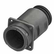
Panel cut out * On request (please consult our Sales Office)
Dimension “L” can be different from the value indicated according to backshells accessories, wires size and some special insert configurations. Dimensions in
122 Go online for data sheets & assembly instructions. Visit www.radiall.com/vansystem and enter the part number. CVBS SHELL
T S R K M ØD L P ØB N Shell size ØD +0 -0.15 ØB ±0.2 L M ±0.2 K ±0.2 N Backshell Thread in inches R ±0.1 S ±0.3 ØT ØT1 ØC ±0.2 P Panel Thickness Max Cable Range ST ST1 ST2 18 30.8 30 95 23.4 4 1”-20 UNEF 27 34.9 M4 4.5 31.7 7.25 14-9 9-4 * 20 34.2 32 95 23.4 4 1” 3/16-18 UNEF 29.4 38.1 M4 4.5 35 7.3 19-14 14-9 * 22 37.4 38 95 23.4 4 1” 3/16-18 UNEF 31.8 41 M4 4.5 38.3 7.3 19-14 14-9 * 24 40.9 45 100 23.4 4 1” 7/16-18 UNEF 34.9 44.5 M4 4.5 41.8 6.85 23-18 18-13 * 28 46.7 48 100 24.4 4 1” 7/16-18 UNEF 39.7 50.8 M5 5.5 47.6 7.8 23-18 18-13 * 32 53.4 55 105 24.4 4 1” 3/4-18 UNS 44.5 57 M5 5.5 54.3 7.5 31-25 25-19 19-13 36 59.6 58 115 24.4 4 2”-18 UNS 49.2 63.5 M5 5.5 60.5 7.5 33-25 25-18 * 40 65.5 65 115 24.4 4 2”1/4-16 UN 55.6 69.8 M5 5.5 66.4 7.5 39-31 31-24 24-16
R ØC ØT 1
mm
CVBS - Bayonet Connector with protected mating ramps
Adapter (AST1 - ST1 - AST2 - ST2 Class only)
Grommet (ST - ST1 - ST2 Class only)
Grommet cone (ST - ST1 - ST2 Class only)
RF Insulating material - Chloroprene rubber
V Fluoride rubber
S Silicone rubber
RF Fire resistant rubber CVBS Series
Bayonet Connector with protected mating ramps Shell Material
030 Shell Type
ST Connector Class
Rear mounting Receptacle
AST with waterproof O-ring (IP67***)
ST with waterproof O-ring and grommet (IP67***)
AST1 with waterproof O-ring (IP67***)
ST1 with waterproof O-ring and grommet (IP67***)
AST2 with waterproof O-ring (IP67***)
ST2 with waterproof O-ring and grommet (IP67***)
T With plastic caps
Receptacle connector with threaded holes
T Connector Modification**
FP Receptacle connector with through holes
FS Receptacle connector with countersunk holes
20-27 Insert Arrangement
S Contact Gender
X Polarization Code**
CR Contact Termination
CD5 Contact Plating
Backshell
Size - Type
S Socket contacts
P Pin contacts
Alternate Positions
- Solder contacts
CR Crimp contacts
LC Less contacts
- Silver plating
CD5 Gold plating F7 Shell finish
F5
Electroless nickel (*)
F7 Black epoxy varnish (*)
F16
CCF - Black passivation (*) - conductive
F26 hard anodization (*)
- Without gasket
G With waterproof panel gasket
G2 With shielded panel gasket
G3 With waterproof shielded panel gasket
N Modification Code** N
Consult our sales office S
123 Go online for data sheets & assembly instructions. Visit www.radiall.com/vansystem and enter the part number.
SHELL
CVBS
Shell
Series Code Shell Type Connector Class
finish
P/N Sample: RF CVBS 030STT 20-27SX CR CD5 F7 G N RF CVBS 030 ST 20-27 S X CR CD5 F7 G N T
(*) RoHS compliance (**) If required *** Protection
IP 67
in the mating area
mated connectors) according to EN 60529 Gasket
Gasket
Shell Material
degree:
(only
with
Backshell
CVBS
- Aluminum
Code
030
G Panel Gasket
CVBS - Bayonet Connector with protected mating ramps
Rear Mounting Receptacle (030) with Backshell Class (AST..M - ST..M)
Connector with backshell with internal cable retention system (on request ST1/ST2 with clamps for cable diameter reduction) with an internal Metric thread
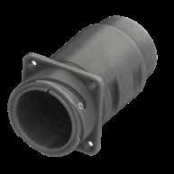
On request (please consult our Sales Office)
Dimension “L” can be different from the value indicated according to backshells accessories, wires size and some special insert configurations.
124 Go online
Visit www.radiall.com/vansystem and enter the part number. CVBS SHELL
for data sheets & assembly instructions.
T S R K M ØD L P ØB N Shell size ØD +0 -0.15 ØB ±0.2 L M ±0.2 K ±0.2 N Backshell Thread Metric R ±0.1 S ±0.3 ØT ØT1 ØC ±0.2 P Panel Thickness Max Cable Range ST ST1 ST2 18 30.8 30 95 23.4 4 M16 - M20 27 34.9 M4 4.5 31.7 7.25 14-9 9-4 * 20 34.2 32 95 23.4 4 M20 29.4 38.1 M4 4.5 35 7.3 19-14 14-9 * 22 37.4 38 95 23.4 4 M20 31.8 41 M4 4.5 38.3 7.3 19-14 14-9 * 24 40.9 45 100 23.4 4 M25 34.9 44.5 M4 4.5 41.8 6.85 23-18 18-13 * 28 46.7 48 100 24.4 4 M25 39.7 50.8 M5 5.5 47.6 7.8 23-18 18-13 * 32 53.4 55 105 24.4 4 M32 - M40 44.5 57 M5 5.5 54.3 7.5 31-25 25-19 19-13 36 59.6 58 120 24.4 4 M32 - M40 49.2 63.5 M5 5.5 60.5 7.5 33-25 25-18 * 40 65.5 65 120 24.4 4 M40 - M50 55.6 69.8 M5 5.5 66.4 7.5 39-31 31-24 24-16
in
R ØC ØT 1
*
Dimensions
mm
Panel cut out
CVBS - Bayonet Connector with protected mating ramps
Grommet (ST - ST1 - ST2 Class only)
RF Insulating material
Grommet cone (ST - ST1 - ST2 Class only)
- Chloroprene rubber V Fluoride rubber
S Silicone rubber
RF Fire resistant rubber
with protected mating ramps
mounting Receptacle ST Connector Class
AST with waterproof O-ring (IP67***)
ST with waterproof O-ring and grommet (IP67***)
AST1 with waterproof O-ring (IP67***)
ST1 with waterproof O-ring and grommet (IP67***)
AST2 with waterproof O-ring (IP67***)
ST2 with waterproof O-ring and grommet (IP67***)
T With plastic caps
Receptacle connector with threaded holes
S Contact Gender
X Polarization Code**
M Backshell internal thread
CR Contact Termination
CD5 Contact Plating
F7 Shell finish
T Connector Modification**
FP Receptacle connector with through holes
FS Receptacle connector with countersunk holes
20-27 Insert Arrangement Size - Type
G Panel Gasket
N Modification Code**
Backshell
S Socket contacts
P Pin contacts
Alternate Positions
M Provided with an internal Metric thread
- Solder contacts
CR Crimp contacts
LC Less contacts
- Silver plating
CD5 Gold plating
F5
Electroless nickel (*)
F7 Black epoxy varnish (*)
F16 CCF - Black passivation (*) - conductive
F26 hard anodization (*)
- Without gasket
G With waterproof panel gasket
G2 With shielded panel gasket
G3 With waterproof shielded panel gasket
N
Consult our sales office S
125 Go online for data sheets &
Visit www.radiall.com/vansystem and enter the part number. CVBS SHELL
Shell finish
assembly instructions.
Series Code Shell Type Connector Class
Gasket P/N Sample: RF CVBS 030STT 20-27SX M CR CD5 F7 G N RF CVBS 030 ST 20-27 S X CR CD5 F7 G N T Shell Material (*) RoHS compliance (**) If required *** Protection degree: IP 67 (only in the mating area with mated connectors) according to EN 60529 Gasket Backshell
AST2
M
Adapter (AST1 - ST1 -
- ST2 Class only)
CVBS Series Code CVBS
Shell Material - Aluminum
Bayonet Connector
030 Shell Type 030 Rear
CVBS - Bayonet Connector with protected mating ramps
Rear Mounting Receptacle (030) with Backshell Class (AST..FS - ST..FS)
Connector with backshell with internal cable retention system (on request ST1/ST2 with clamps for cable diameter reduction) with a special adapter for rubber conduits
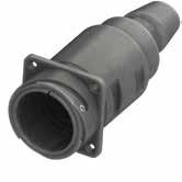
Please consult our Sales Office for further details about this dimension and according to conduit size.
126 Go online
data sheets
Visit www.radiall.com/vansystem and enter the part number. CVBS SHELL
for
& assembly instructions.
T S R K M ØD L P ØB Ø 1 A Ø 2 A Shell size ØD +0 -0.15 ØB ±0.2 L M ±0.2 K ±0.2 R ±0.1 S ±0.3 ØT ØT1 ØC ±0.2 P Panel Thickness Max Cable Range ST ST1 ST2 18 30.8 30 110 23.4 4 27 34.9 M4 4.5 31.7 7.25 14-9 9-4 * 20 34.2 32 110 23.4 4 29.4 38.1 M4 4.5 35 7.3 19-14 14-9 * 22 37.4 38 110 23.4 4 31.8 41 M4 4.5 38.3 7.3 19-14 14-9 * 24 40.9 45 115 23.4 4 34.9 44.5 M4 4.5 41.8 6.85 23-18 18-13 * 28 46.7 48 115 24.4 4 39.7 50.8 M5 5.5 47.6 7.8 23-18 18-13 * 32 53.4 55 120 24.4 4 44.5 57 M5 5.5 54.3 7.5 31-25 25-19 19-13 36 59.6 58 135 24.4 4 49.2 63.5 M5 5.5 60.5 7.5 33-25 25-18 * 40 65.5 65 135 24.4 4 55.6 69.8 M5 5.5 66.4 7.5 39-31 31-24 24-16 Dimension “L” can be different from the value indicated according to backshells accessories, wires size and some special insert configurations. Dimensions in mm R ØC ØT 1 Panel cut out *
request
* * Rubber Conduit not included
Backshell Conduit Size ØA1* ØA2* FS2015 20 15 FS2520 25 20 FS2722 27 22 FS3328 33 28 FS3530 35 30 FS4035 40 35 FS4540 45 40 FS5045 50 45 FS5945 59 45
On
(please consult our Sales Office)
CVBS - Bayonet Connector with protected mating ramps
Shell Material
Backshell Conduits size
RF Insulating material
Grommet cone (ST - ST1 - ST2 Class only)
- Chloroprene rubber
V Fluoride rubber
S Silicone rubber
RF Fire resistant rubber
CVBS Series Code CVBS Bayonet Connector with protected mating ramps
Shell Material - Aluminum
030 Shell Type 030 Rear mounting Receptacle
ST Connector Class
T Connector Modification**
Grommet (ST - ST1 - ST2 Class only) Gasket P/N Sample:
AST with waterproof O-ring (IP67***)
ST with waterproof O-ring and grommet (IP67***)
AST1 with waterproof O-ring (IP67***)
ST1 with waterproof O-ring and grommet (IP67***)
AST2 with waterproof O-ring (IP67***)
ST2 with waterproof O-ring and grommet (IP67***)
T With plastic caps
Receptacle connector with threaded holes
FP Receptacle connector with through holes
FS Receptacle connector with countersunk holes
20-27 Insert Arrangement Size - Type
S Contact Gender
X Polarization Code**
FS Backshell Conduits size
Backshell
S Socket contacts
P Pin contacts
Alternate Positions
FS
Provided with a special adapter for rubber conduits
xxxx Conduit Size xxxx ØA1/ØA2
CR Contact Termination
CD5 Contact Plating
F7 Shell finish
- Solder contacts
CR Crimp contacts
LC Less contacts
- Silver plating
CD5 Gold plating
F5
Electroless nickel (*)
F7 Black epoxy varnish (*)
F16
G Panel Gasket
N Modification Code**
CCF - Black passivation (*) - conductive
F26 hard anodization (*)
- Without gasket
G With waterproof panel gasket
G2 With shielded panel gasket
G3 With waterproof shielded panel gasket
N
S
Consult our sales office
127 Go online for data sheets
Visit www.radiall.com/vansystem and enter the part number.
SHELL
& assembly instructions.
CVBS
RF
030STT 20-27SX FSxxxx CR CD5 F7 G N (*) RoHS compliance (**) If required *** Protection degree: IP 67 (only in the mating area with mated connectors) according to EN 60529 Gasket Backshell Adapter (AST1 - ST1 - AST2 - ST2 Class only)
Shell
RF
030 ST 20-27 S X CR CD5 F7 G N T
CVBS
Series Code Shell Type Connector Class
finish
CVBS
FS
xxxx
CVBS - Bayonet Connector with protected mating ramps
Rear Mounting Receptacle (03 - 03A - 03R) unable to accept Rear Accessories
128 Go online for data sheets & assembly instructions. Visit www.radiall.com/vansystem and enter the part number. CVBS SHELL
T S R P K M L ØD ØN Shell size ØD +0 -0.15 L K ±0.2 M ±0.2 ØN Max R ±0.1 S ±0.3 ØT ØT1 ØC ±0.2 P Panel Thickness Max 10SL 18.2 30 2.8 18.2 16.1 18.2 25.4 M4 4.5 19.1 6 14S 24.6 30 3.2 18.6 19.2 23 30.2 M4 4.5 25.5 7.2 16S 27.4 30 3.2 18.6 22.5 24.6 32.5 M4 4.5 28.3 7.2 16 27.4 38.8 3.2 23.05 22.4 24.6 32.5 M4 4.5 28.3 5.35 18 30.8 38.5 4 23.4 25.6 27 34.9 M4 4.5 31.7 7.25 20 34.2 39.1 4 23.4 28.8 29.4 38.1 M4 4.5 35 7.3 22 37.4 39.3 4 23.4 32.2 31.8 41 M4 4.5 38.3 7.3 24 40.9 38.8 4 23.4 35.3 34.9 44.5 M4 4.5 41.8 6.85 28 46.7 39.1 4 24.4 41.5 39.7 50.8 M5 5.5 47.6 7.8 32 53.4 38.4 4 24.4 47.8 44.5 57 M5 5.5 54.3 7.5 36 59.6 39.9 4 24.4 52.6 49.2 63.5 M5 5.5 60.5 7.5 40 65.5 38.5 4 24.4 59.2 55.6 69.8 M5 5.5 66.4 7.5 Dimension
different
the value indicated according to wires size
some special insert configurations. Dimensions in mm R ØC ØT 1
“L” can be
from
and
Panel cut out
CVBS - Bayonet Connector with protected mating ramps
Plating
Rear mounting receptacle connector unable to accept rear accessories
Rear mounting receptacle connector non enviromental (equivalent MS3103A..B bayonet version)
Rear mounting receptacle connector enviromental seal (unable to accept rear accessories)
connector with threaded holes
Receptacle connector with through holes
connector with countersunk holes
129 Go online for data sheets & assembly instructions. Visit www.radiall.com/vansystem and enter the part number.
SHELL Series Code Shell Type Shell finish
CVBS
(*) RoHS compliance P/N Sample: RF CVBS 03T 20-27SX CR CD5 F7 G N RF CVBS 03 20-27 S X CR CD5 F7 G N T Shell Material (**) If required RF
- Chloroprene rubber V Fluoride rubber S Silicone rubber RF Fire resistant rubber CVBS Series Code CVBS Bayonet Connector with protected mating ramps Shell Material - Aluminum 03 Shell Type 03
03A
03R
T
T With plastic caps -
FP
FS
20-27 Insert Arrangement Size - Type S
S Socket contacts P Pin contacts X
Code** Alternate Positions CR
- Solder
CR Crimp contacts LC Less contacts DS PCB
- Silver
CD5 Gold
F5 Electroless
(*) F7 Black
(*) F16 CCF
F26 hard anodization (*) G
- Without gasket G With waterproof panel gasket G2 With shielded panel gasket G3 With waterproof shielded panel gasket N Modification Code** N Consult our sales office S
Insulating material
Connector Modification**
Receptacle
Receptacle
Contact Gender
Polarization
Contact Termination
contacts
contacts CD5 Contact
plating
plating F7 Shell finish
nickel
epoxy varnish
- Black passivation (*) - conductive
Panel Gasket
CVBS - Bayonet Connector with protected mating ramps
In-Line Receptacle (01) with Backshell Class (A - DA - RA)
Connector with backshell provided with an external thread suitable for MS3057…A or C type Cable-Clamps (to be ordered separately).
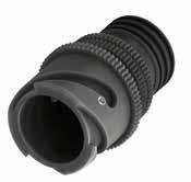
Dimensions in mm
Dimension “L” can be different from the value indicated according to backshells accessories, wires size and some special insert configurations.
130 Go online for data sheets & assembly instructions. Visit www.radiall.com/vansystem and enter the part number. CVBS SHELL
L ØB N K M ØD ØQ Shell size ØD +0 -0.15 ØQ Max ØB ±0.2 L K ±0.2 M ±0.2 N Backshell Thread in inches 10SL 18.2 22 20 41 2.8 14.2 5/8”-24 UNEF 14S 24.6 29 24 42.5 3.2 14.5 3/4”-20 UNEF 16S 27.4 31 27 42.5 3.2 14.2 7/8”-20 UNEF 16 27.4 31 27 50 3.2 19 7/8”-20 UNEF 18 30.8 34 30 52 4 19 1”-20 UNEF 20 34.2 37 32 51 4 19 1” 3/16-18 UNEF 22 37.4 40 37 54 4 19.7 1” 3/16-18 UNEF 24 40.9 44 40 54 4 20.6 1” 7/16-18 UNEF 28 46.7 49.5 45 62 4 20.6 1” 7/16-18 UNEF 32 53.4 56 52 63 4 22.2 1” 3/4-18 UNS 36 59.6 62.5 58 63 4 22.2 2”-18 UNS 40 65.5 68.5 63.2 63 4 22.2 2”1/4-16 UN
CVBS - Bayonet Connector with protected mating ramps
RF Insulating material - Chloroprene rubber
Silicone rubber
resistant rubber
Contact Gender
Connector Class
Socket contacts
Pin contacts
Polarization Code** Alternate Positions CR Contact Termination
- Solder contacts CR Crimp contacts
LC Less contacts CD5 Contact Plating - Silver plating
CD5 Gold plating
F5 Electroless nickel (*) F7 Black epoxy varnish (*)
F16 CCF - Black passivation (*) - conductive
F26 hard anodization (*)
Consult our sales office
131 Go online for data sheets & assembly instructions. Visit www.radiall.com/vansystem and enter the part number.
SHELL
CVBS
Shell
ØB N
Series Code Shell Type Connector Class
finish
Gasket (DA-RA
P/N Sample: RF CVBS 01DAT 20-27SX CR CD5 F7 N RF CVBS 01 DA 20-27 S X CR CD5 F7 N T Shell Material (*) RoHS compliance
required ***
60529
S
Code CVBS Bayonet
Shell Material - Aluminum 01 Shell Type 01 In-line receptacle DA
A non watertight DA with waterproof O-ring (IP67***) RA with
O-ring
grommet
T With
caps
Size - Type S
S
X
Backshell Grommet cone (RA Class only) Grommet (RA Class only)
Class only)
(**) If
Protection degree: IP 67 (only in the mating area with mated connectors) according to EN
V Fluoride rubber
RF Fire
CVBS Series
Connector with protected mating ramps
waterproof
and
(IP67***) T Connector Modification**
plastic
20-27 Insert Arrangement
P
F7
finish
Shell
N
N
S
Modification Code**
CVBS - Bayonet Connector with protected mating ramps
In-Line Receptacle (01) with Backshell Class (LA - LDA - LRA)
Connector with long backshell provided with an external thread suitable for MS3057…A or C type Cable-Clamps (to be ordered separately).
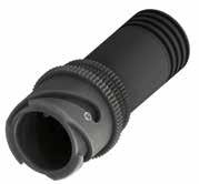
Dimensions in mm
Dimension “L” can be different from the value indicated according to backshells accessories, wires size and some special insert configurations.
132 Go online for data sheets & assembly instructions. Visit www.radiall.com/vansystem and enter the part number. CVBS SHELL
L ØB N K M ØD ØQ Shell size ØD +0 -0.15 ØQ Max ØB ±0.2 L K ±0.2 M ±0.2 N Backshell Thread in inches 10SL 18.2 22 20 67 2.8 14.2 5/8”-24 UNEF 14S 24.6 29 24 67 3.2 14.5 3/4”-20 UNEF 16S 27.4 31 27 67 3.2 14.2 7/8”-20 UNEF 16 27.4 31 27 77 3.2 19 7/8”-20 UNEF 18 30.8 34 30 77.5 4 19 1”-20 UNEF 20 34.2 37 32 78 4 19 1” 3/16-18 UNEF 22 37.4 40 37 79 4 19.7 1” 3/16-18 UNEF 24 40.9 44 40 81 4 20.6 1” 7/16-18 UNEF 28 46.7 49.5 45 81 4 20.6 1” 7/16-18 UNEF 32 53.4 56 52 95.5 4 22.2 1” 3/4-18 UNS 36 59.6 62.5 58 95.5 4 22.2 2”-18 UNS 40 65.5 68.5 63.2 95.5 4 22.2 2”1/4-16 UN
CVBS - Bayonet Connector with protected mating ramps
Series Code Shell Type Connector Class Shell finish
Grommet (LRA Class only)
Grommet cone (LRA Class only)
(LDA-LRA Class only)
RF Insulating material - Chloroprene rubber V Fluoride rubber S Silicone rubber RF Fire resistant rubber
CVBS Series Code CVBS Bayonet Connector with protected mating ramps
CR Contact Termination
LDA Connector Class LA non watertight LDA with waterproof O-ring (IP67***) LRA with waterproof O-ring and grommet (IP67***)
T Connector Modification** T With plastic caps
20-27 Insert Arrangement Size - Type S Contact Gender S Socket contacts P Pin contacts X Polarization Code** Alternate Positions
- Solder contacts
CR Crimp contacts
LC Less contacts
CD5 Contact Plating - Silver plating
Modification Code**
CD5 Gold plating
F5 Electroless nickel (*)
F7 Black epoxy varnish (*)
F16
CCF - Black passivation (*) - conductive
F26 hard anodization (*)
Consult our sales office
RoHS compliance (**) If required *** Protection degree: IP 67 (only in the mating area with mated connectors) according to EN 60529
P/N Sample:
133 Go online for data sheets & assembly instructions. Visit www.radiall.com/vansystem and enter the part number.
SHELL
CVBS
RF CVBS 01 LDA 20-27 S X CR CD5 F7 N T Shell
ØB N
RF CVBS 01LDAT 20-27SX CR CD5 F7 N
Material
Backshell
Gasket
(*)
01
01
Shell Material - Aluminum
Shell Type
In-line receptacle
F7 Shell finish
N
N
S
CVBS - Bayonet Connector with protected mating ramps
In-Line Receptacle (01) with Backshell Class (AF - F)
Connector provided with backshell, MS3057...A type Cable-Clamp and bushing MS3420...(for single wire)
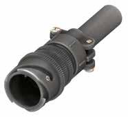
134 Go online for data sheets & assembly instructions. Visit www.radiall.com/vansystem and enter the part number. CVBS SHELL
L ØB A F Ø K M ØD ØQ Shell size ØD +0 -0.15 ØQ Max ØB ±0.2 L K ±0.2 M ±0.2 A max ØF cable max dimension 10SL 18.2 22 20 51 2.8 14.2 22.5 5.6 14S 24.6 29 24 54.5 3.2 14.5 28 7.9 16S 27.4 31 27 56 3.2 14.2 30 11 16 27.4 31 27 63.5 3.2 19 30 11 18 30.8 34 30 66.5 4 19 31.7 14.2 20 34.2 37 32 66.5 4 19 37.5 15.8 22 37.4 40 37 69.5 4 19.7 37.5 15.8 24 40.9 44 40 69.5 4 20.6 43.5 19 28 46.7 49.5 45 77.5 4 20.6 43.5 19 32 53.4 56 52 78.5 4 22.2 51.7 23.8 36 59.6 62.5 58 78.5 4 22.2 58.5 31.7 40 65.5 68.5 63.2 92 4 22.2 68.5 34.9 Dimension
can be different
value indicated according
backshells accessories, wires size
some special insert configurations. Dimensions in mm IP54
“L”
from the
to
and
CVBS - Bayonet Connector with protected mating ramps
Fluoride rubber
Silicone rubber RF Fire resistant rubber
Contact Gender
Socket contacts P Pin contacts X Polarization Code** Alternate Positions CR Contact Termination - Solder contacts CR Crimp contacts
LC Less contacts
CD5 Gold plating
Cable-Clamp MS3057...A bushing MS3420 (**) If required RF Insulating material - Chloroprene rubber
CD5 Contact Plating - Silver plating
F5 Electroless nickel (*)
F7 Black epoxy varnish (*)
F16
CCF - Black passivation (*) - conductive
F26 hard anodization (*)
135 Go online for data sheets & assembly instructions. Visit www.radiall.com/vansystem and enter the part number.
SHELL
CVBS
Series Code Shell Type Connector Class Shell finish
RF CVBS 01AFT 20-27SX CR CD5 F7 N RF CVBS 01 AF 20-27 S X CR CD5 F7 N T
Grommet cone
Grommet
only) Gasket H A F Ø ØB ØB A F Ø
CVBS Series Code CVBS Bayonet
protected mating ramps Shell Material - Aluminum 01 Shell Type 01 In-line receptacle
F with waterproof O-ring
grommet (IP54) AF with waterproof O-ring (IP54)
Modification** T With plastic caps
Size - Type
(*) RoHS compliance P/N Sample:
Shell Material Backshell
(F Class only)
(F Class
V
S
Connector with
AF Connector Class
and
T Connector
20-27 Insert Arrangement
S
S
F7 Shell finish
N
N
S
Modification Code**
Consult our sales office
CVBS - Bayonet Connector with protected mating ramps
In-Line Receptacle (01) with Backshell Class (LAF - LF)
Connector provided with long backshell, MS3057...A type Cable-Clamp and bushing MS3420... (for single wire)
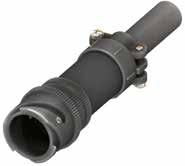
Dimension “L” can be different from the value indicated according to backshells accessories, wires size and some special insert configurations.
136 Go online for data sheets & assembly instructions. Visit www.radiall.com/vansystem and enter the part number. CVBS SHELL
L ØB A F Ø K M ØD ØQ Shell size ØD +0 -0.15 ØQ Max ØB ±0.2 L K ±0.2 M ±0.2 A max ØF cable max dimension 10SL 18.2 22 20 77 2.8 14.2 22.5 5.6 14S 24.6 29 24 79 3.2 14.5 28 7.9 16S 27.4 31 27 80.5 3.2 14.2 30 11 16 27.4 31 27 90.5 3.2 19 30 11 18 30.8 34 30 93 4 19 31.7 14.2 20 34.2 37 32 93.5 4 19 37.5 15.8 22 37.4 40 37 94.5 4 19.7 37.5 15.8 24 40.9 44 40 96.5 4 20.6 43.5 19 28 46.7 49.5 45 96.5 4 20.6 43.5 19 32 53.4 56 52 111 4 22.2 51.7 23.8 36 59.6 62.5 58 111 4 22.2 58.5 31.7 40 65.5 68.5 63.2 124.5 4 22.2 68.5 34.9
Dimensions in mm IP54
CVBS - Bayonet Connector with protected mating ramps
Shell Material
Series Code Shell Type Connector Class Shell finish
Grommet (LF Class only)
RF Insulating material
Grommet cone (LF Class only)
Backshell
- Chloroprene rubber V Fluoride rubber S Silicone rubber RF Fire resistant rubber
CVBS Series Code CVBS Bayonet Connector with protected mating ramps
Shell Material - Aluminum
LAF Connector Class
Connector
20-27 Insert Arrangement
CR Contact Termination
F7 Shell finish
X Polarization Code** Alternate Positions
- Solder contacts
LC Less contacts
CD5 Contact Plating - Silver plating
CD5 Gold plating
Cable-Clamp MS3057...A bushing MS3420 (**) If required
CR Crimp contacts
- Type S Contact Gender S Socket contacts P Pin contacts
F5 Electroless nickel (*)
F7 Black epoxy varnish (*)
F16
CCF - Black passivation (*) - conductive
F26 hard anodization (*)
Consult our sales office
137 Go online for data sheets & assembly instructions. Visit www.radiall.com/vansystem and enter the part number.
SHELL
CVBS
(*) RoHS compliance
RF CVBS 01 LAF 20-27 S X CR CD5 F7 N T
P/N Sample: RF CVBS 01LAFT 20-27SX CR CD5 F7 N
Gasket
01
01
Shell Type
In-line receptacle
LAF
LF with waterproof O-ring and grommet (IP54)
with waterproof O-ring (IP54) T
Modification** T With plastic caps
Size
N Modification Code** N
S
CVBS - Bayonet Connector with protected mating ramps
In-Line Receptacle (01) with Backshell Class (AC - ACF)
Connector provided with backshell, MS3057...C type Cable-Clamp (for jacketed cable)
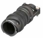
Dimension “L” can be different from the value indicated according to backshells accessories, wires size and some special insert configurations.
138 Go online for data sheets & assembly instructions. Visit www.radiall.com/vansystem and enter the part number. CVBS SHELL
L ØB A Ø F K M ØD ØQ Shell size ØD +0 -0.15 ØQ Max ØB ±0.2 L K ±0.2 M ±0.2 A max ØF cable dimension Min Max 10SL 18.2 22 20 65 2.8 14.2 23 2.4 7.9 14S 24.6 29 24 66.5 3.2 14.5 26 5.8 11.2 16S 27.4 31 27 67.5 3.2 14.2 28.5 8 13.5 16 27.4 31 27 75 3.2 19 28.5 8 13.5 18 30.8 34 30 78.5 4 19 32 9.6 15.9 20 34.2 37 32 77.5 4 19 37.5 11.3 19 22 37.4 40 37 80.5 4 19.7 37.5 11.3 19 24 40.9 44 40 87.5 4 20.6 43.5 15.5 23.8 28 46.7 49.5 45 95.5 4 20.6 43.5 15.5 23.8 32 53.4 56 52 101 4 22.2 54 23.4 31.8 36 59.6 62.5 58 105.5 4 22.2 58 25.4 35 40 65.5 68.5 63.2 107 4 22.2 63.5 30 41.3
Dimensions in mm IP67
CVBS - Bayonet Connector with protected mating ramps
Grommet cone (ACF Class only) Grommet (ACF Class only)
RF Insulating material - Chloroprene rubber
Fluoride rubber
Silicone rubber
Fire resistant rubber CVBS Series Code
Polarization
Alternate Positions
Contact Termination - Solder contacts
Crimp contacts
LC Less contacts CD5 Contact Plating - Silver plating
CD5 Gold plating F7 Shell finish
F5 Electroless nickel (*)
F7 Black epoxy varnish (*)
F16
CCF - Black passivation (*) - conductive
F26 hard anodization (*)
139 Go online for data sheets & assembly instructions. Visit www.radiall.com/vansystem and enter the part number.
SHELL
CVBS
A Ø F ØB H Cable-Clamp MS3057...C
Type
Shell finish
Backshell
Gasket
Series Code Shell
Connector Class
(*) RoHS compliance P/N Sample: RF CVBS 01ACT 20-27SX CR CD5 F7 N RF CVBS 01 AC 20-27 S X CR CD5 F7 N T Shell Material (**)
required
V
S
CVBS
01
Type 01 In-line receptacle
AC
ACF
Modification** T
caps
Size - Type S
X
If
RF
Bayonet Connector with protected mating ramps Shell Material - Aluminum
Shell
AC Connector Class
with waterproof O-ring (IP67)
with waterproof O-ring and grommet (IP67) T Connector
With plastic
20-27 Insert Arrangement
Contact Gender S Socket contacts P Pin contacts
Code**
CR
CR
N
N
S
Modification Code**
Consult our sales office
CVBS - Bayonet Connector with protected mating ramps
In-Line Receptacle (01) with Backshell Class (ACB)
Connector provided with backshell, MS3057...C type Cable-Clamp and bushing MS 3420A (for jacketed cable)
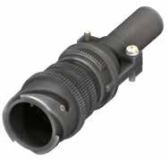
140 Go online for data sheets & assembly instructions. Visit www.radiall.com/vansystem and enter the part number. CVBS SHELL
L ØB A F Ø K M ØD ØQ Shell size ØD +0 -0.15 ØQ Max ØB ±0.2 L K ±0.2 M ±0.2 A max ØF max cable size 10SL 18.2 22 20 65 2.8 14.2 23 5.6 14S 24.6 29 24 66.5 3.2 14.5 26 7.9 16S 27.4 31 27 67.5 3.2 14.2 28.5 11.1 16 27.4 31 27 75 3.2 19 28.5 11.1 18 30.8 34 30 78.5 4 19 32 11.1 20 34.2 37 32 77.5 4 19 37.5 13.7 22 37.4 40 37 80.5 4 19.7 37.5 13.7 24 40.9 44 40 87.5 4 20.6 43.5 19 28 46.7 49.5 45 95.5 4 20.6 43.5 19 32 53.4 56 52 101 4 22.2 54 23.8 36 59.6 62.5 58 105.5 4 22.2 58 28.5 40 65.5 68.5 63.2 107 4 22.2 63.5 31.8 Dimension “L” can be different from the value indicated according to backshells accessories, wires size and some special insert configurations. Dimensions in mm
CVBS - Bayonet Connector with protected mating ramps
Series Code Shell Type Connector Class Shell finish
RF Insulating material - Chloroprene rubber V Fluoride rubber S Silicone rubber RF Fire resistant rubber
CVBS Series Code CVBS Bayonet Connector with protected mating ramps
Shell Material - Aluminum 01 Shell Type 01 In-line receptacle
ACB Connector Class ACB with waterproof O-ring
T Connector Modification** T With plastic caps 20-27 Insert Arrangement Size - Type S Contact Gender S Socket contacts P Pin contacts X Polarization Code** Alternate Positions
CR Contact Termination - Solder contacts CR Crimp contacts
LC Less contacts
CD5 Contact Plating - Silver plating
F7 Shell finish
CD5 Gold plating
F5 Electroless nickel (*)
F7 Black epoxy varnish (*)
F16
CCF - Black passivation (*) - conductive
F26 hard anodization (*) N Modification Code** N
Consult our sales office S
(*) RoHS compliance
(**) If required
141 Go online for data sheets & assembly instructions. Visit www.radiall.com/vansystem and enter the part number.
SHELL
CVBS
RF CVBS 01
20-27
X CR CD5 F7 N T
Gasket ØB A F Ø
MS3057...C bushing MS3420A
P/N Sample: RF CVBS 01ACBT 20-27SX CR CD5 F7 N
ACB
S
Shell Material Backshell
Cable-Clamp
CVBS - Bayonet Connector with protected mating ramps
In-Line Receptacle (01) with Backshell Class (LAC - LACF)
Connector provided with long backshell, MS3057...C type Cable-Clamp (for jacketed cable)
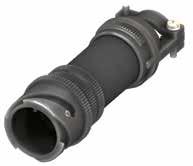
142 Go online for data sheets & assembly instructions. Visit www.radiall.com/vansystem and enter the part number. CVBS SHELL
L ØB A Ø F K M ØD ØQ Shell size ØD +0 -0.15 ØQ Max ØB ±0.2 L K ±0.2 M ±0.2 A max ØF cable dimension Min Max 10SL 18.2 22 20 91 2.8 14.2 23 2.4 7.9 14S 24.6 29 24 91 3.2 14.5 26 5.8 11.2 16S 27.4 31 27 92 3.2 14.2 28.5 8 13.5 16 27.4 31 27 102 3.2 19 28.5 8 13.5 18 30.8 34 30 105 4 19 32 9.6 15.9 20 34.2 37 32 105 4 19 37.5 11.3 19 22 37.4 40 37 106 4 19.7 37.5 11.3 19 24 40.9 44 40 114.5 4 20.6 43.5 15.5 23.8 28 46.7 49.5 45 114.5 4 20.6 43.5 15.5 23.8 32 53.4 56 52 133.5 4 22.2 54 23.4 31.8 36 59.6 62.5 58 138 4 22.2 58 25.4 35 40 65.5 68.5 63.2 139.5 4 22.2 63.5 30 41.3 Dimension
Dimensions in mm IP67
“L” can be different from the value indicated according to backshells accessories, wires size and some special insert configurations.
CVBS - Bayonet Connector with protected mating ramps
Shell Material
Series Code Shell Type Connector Class Shell finish
Grommet (LACF Class only)
Grommet cone (LACF Class only)
Backshell
RF Insulating material - Chloroprene rubber V Fluoride rubber S Silicone rubber RF Fire resistant rubber
CVBS Series Code CVBS Bayonet Connector with protected mating ramps
Shell Material - Aluminum
Connector
X Polarization Code** Alternate Positions
CR Contact Termination - Solder contacts
LC Less contacts
CD5 Contact Plating - Silver plating
CD5 Gold plating F7 Shell finish
T Connector Modification** T With plastic caps 20-27 Insert Arrangement Size - Type S Contact Gender S Socket contacts P Pin contacts
CR Crimp contacts
F5 Electroless nickel (*)
F7 Black epoxy varnish (*)
F16 CCF - Black passivation (*) - conductive
F26 hard anodization (*) N Modification Code**
Consult our sales office
(*) RoHS compliance
143 Go online for data sheets & assembly
Visit www.radiall.com/vansystem and enter the part number.
SHELL
instructions.
CVBS
RF CVBS 01 LAC 20-27 S X CR CD5 F7 N T
P/N Sample: RF CVBS 01LACT 20-27SX CR CD5 F7 N
A Ø F ØB
Gasket
Cable-Clamp MS3057...C (**) If required
01
Type 01 In-line receptacle
Shell
LAC
Class LAC with waterproof O-ring (IP67) LACF with waterproof O-ring and grommet (IP67)
N
S
CVBS - Bayonet Connector with protected mating ramps
In-Line Receptacle (01) with Backshell Class (AB)
Connector provided with backshell, MS3057...B type Cable-Clamp (for jacketed cable)
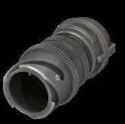
Dimension “L” can be different from the value indicated according to backshells accessories, wires size and some special insert configurations.
144 Go online for data sheets & assembly instructions. Visit www.radiall.com/vansystem and enter the part number. CVBS SHELL
L ØB A Ø F K M ØD ØQ Shell size ØD +0 -0.15 ØQ Max ØB ±0.2 L K ±0.2 M ±0.2 A max ØF cable dimension Min Max 10SL 18.2 22 20 48.4 2.8 14.2 23 2.4 7.9 14S 24.6 29 24 56.1 3.2 14.5 26 5.8 11.2 16S 27.4 31 27 57.3 3.2 14.2 28.5 8 13.5 16 27.4 31 27 63.3 3.2 19 28.5 8 13.5 18 30.8 34 30 68 4 19 32 9.6 15.9 20 34.2 37 32 69.2 4 19 37.5 11.3 19 22 37.4 40 37 71.2 4 19.7 37.5 11.3 19 24 40.9 44 40 76.3 4 20.6 43.5 15.5 23.8 28 46.7 49.5 45 83.3 4 20.6 43.5 15.5 23.8 32 53.4 56 52 85.1 4 22.2 54 23.4 31.8 36 59.6 62.5 58 88.2 4 22.2 58 25.4 35 40 65.5 68.5 63.2 91.5 4 22.2 63.5 30 41.3
Dimensions in mm
CVBS - Bayonet Connector with protected mating ramps
Series Code Shell Type Connector Class Shell finish
Shell Material Backshell Gasket
RF Insulating material - Chloroprene rubber V Fluoride rubber S Silicone rubber RF Fire resistant rubber
CVBS Series Code CVBS Bayonet Connector with protected mating ramps
Shell Material - Aluminum 01 Shell Type 01 In-line receptacle
AB Connector Class AB with waterproof O-ring
T Connector Modification** T With plastic caps
20-27 Insert Arrangement Size - Type S Contact Gender S Socket contacts P Pin contacts X Polarization Code** Alternate Positions
CR Contact Termination
- Solder contacts CR Crimp contacts
LC Less contacts
CD5 Contact Plating - Silver plating
CD5 Gold plating F7 Shell finish
F5 Electroless nickel (*)
F7 Black epoxy varnish (*)
F16 CCF - Black passivation (*) - conductive
F26 hard anodization (*) N Modification Code** N
Consult our sales office S
(*) RoHS compliance
(**) If required
145 Go online for data sheets &
Visit www.radiall.com/vansystem and enter the part number.
SHELL
assembly instructions.
CVBS
RF CVBS 01 AB 20-27
X CR CD5 F7 N T
A Ø F ØB
P/N Sample: RF CVBS 01ABT 20-27SX CR CD5 F7 N
S
Cable-Clamp MS3057..B
CVBS - Bayonet Connector with protected mating ramps
In-Line Receptacle (01) with Backshell Class (ASF)
Connector provided with backshell, MS3057...A type Cable-Clamp (for single wire)
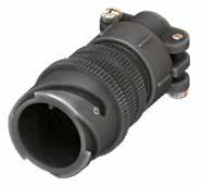
146 Go online for data sheets & assembly instructions. Visit www.radiall.com/vansystem and enter the part number. CVBS SHELL
L ØB A F Ø K M ØD ØQ Shell size ØD +0 -0.15 ØQ Max ØB ±0.2 L K ±0.2 M ±0.2 A max ØF cable max dimension 10SL 18.2 22 20 51 2.8 14.2 22.5 8 14S 24.6 29 24 54.5 3.2 14.5 28 11 16S 27.4 31 27 56 3.2 14.2 30 14.2 16 27.4 31 27 63.5 3.2 19 30 14.2 18 30.8 34 30 66.5 4 19 31.7 15.8 20 34.2 37 32 66.5 4 19 37.5 19 22 37.4 40 37 69.5 4 19.7 37.5 19 24 40.9 44 40 69.5 4 20.6 43.5 23.8 28 46.7 49.5 45 77.5 4 20.6 43.5 23.8 32 53.4 56 52 78.5 4 22.2 51.7 31.7 36 59.6 62.5 58 78.5 4 22.2 58.5 35 40 65.5 68.5 63.2 92 4 22.2 68.5 41.2 Dimension
can be different
value
size
special
Dimensions in mm
“L”
from the
indicated according to backshells accessories, wires
and some
insert configurations.
CVBS - Bayonet Connector with protected mating ramps
Series Code Shell Type Connector Class
Cable-Clamp MS3057...A Grommet cone Grommet Gasket
RF Insulating material
- Chloroprene rubber V Fluoride rubber S Silicone rubber RF Fire resistant rubber
ASF Connector Class ASF with waterproof O-ring and grommet
T Connector Modification** T With plastic caps
20-27 Insert Arrangement Size - Type
S Contact Gender S Socket contacts
P Pin contacts
X Polarization Code** Alternate Positions
CR Contact Termination
CD5 Contact Plating
- Solder contacts
CR Crimp contacts
LC Less contacts
- Silver plating
CD5 Gold plating F7 Shell finish
F5 Electroless nickel (*)
F7 Black epoxy varnish (*)
F16
CCF - Black passivation (*) - conductive
F26 hard anodization (*) N Modification Code** N
Consult our sales office S
(*) RoHS compliance
147 Go online for data sheets & assembly instructions. Visit www.radiall.com/vansystem and enter the part number.
SHELL
CVBS
Shell finish
RF CVBS 01 ASF 20-27 S X CR CD5 F7 N T
P/N Sample: RF CVBS 01ASFT 20-27SX CR CD5 F7 N
Shell Material (**) If required
CVBS
CVBS Series Code
Bayonet Connector with protected mating ramps Shell Material - Aluminum 01 Shell Type 01 In-line receptacle
ØB A F Ø
Backshell
CVBS - Bayonet Connector with protected mating ramps
In-Line Receptacle (01) with Backshell Class (DA...M - RA...M - DA...PG - RA...PG)
Connector with backshell provided with an internal Metric or PG thread suitable for Cable Glands or conduit adapters.
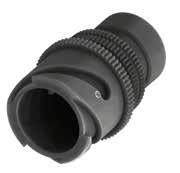
Dimensions “L1 and L2” can be different from the value indicated according to backshells accessories, wires size and some special insert configurations.
Dimensions in mm (...) The threads in parentheses are versions on request with non standard backshell length (the dimensions L2 and Z are different from this page indication). Please consult our sales office for the specific dimensions.
148 Go online for data sheets & assembly instructions. Visit www.radiall.com/vansystem and enter the part number. CVBS SHELL
K M ØD ØQ L2 L1 ØB N Z Shell size ØD +0 -0.15 ØQ Max ØB ±0.2 M ±0.2 K ±0.2 Z min L1 N Backshell Metric thread L2 M N Backshell PG Thread L2 PG 10SL 18.2 22 20 14.2 2.8 8 18,2 M12 - M16 32 (PG9) - PG13.5 26 14S 24.6 29 24 14.5 3.2 9 19,3 M12 - M16 - (M20) - (M25) 30 (PG9) - PG11 - PG13.5 - (PG16) 30 16S 27.4 31 27 14.2 3.2 9 18,5 (M16) - M20 40 PG13.5 - (PG16) 38 16 27.4 31 27 19 3.2 9 24,4 M20 45 - 40 18 30.8 34 30 19 4 9 24 M20 - M25 50 (PG11) - (PG13.5) - PG16 - PG21 50 20 34.2 37 32 19 4 9 24,2 M16 - M20 - M25 - (M32) 50 PG11-PG13.5-PG16-PG21-PG29 50 22 37.4 40 37 19.7 4 10 24,5 M16 - M20 - M25 - M32 50 PG13.5 - (PG16) - (PG29) 50 24 40.9 44 40 20.6 4 10 25,7 M20 - M25 - M32 - M40 50 PG16 - PG21 - PG29 50 28 46.7 49.5 45 20.6 4 10 26,1 (M25) - M32 - M40 63 PG21 - PG29 - PG36 60 32 53.4 56 52 22.2 4 10 27,9 (M25) - (M32) - M40 55 PG21 - (PG29) - PG36 60 36 59.6 62.5 58 22.2 4 13 28,7 M40 - M50 56 PG29 - (PG36) - (PG42) 65 40 65.5 68.5 63.2 22.2 4 13 28 M40 - (M50) - M63 65 PG29 - (PG36) - (PG42) - (PG48) 65
CVBS - Bayonet Connector with protected mating ramps
Provided with an internal PG thread
Solder contacts
Crimp contacts LC Less contacts CD5 Contact Plating
CD5 Gold plating
F5 Electroless nickel (*) F7 Black epoxy varnish (*)
F16 CCF - Black passivation (*) - conductive F26 hard anodization (*)
149 Go online for data sheets & assembly instructions. Visit www.radiall.com/vansystem and enter the part number.
SHELL Series
Shell Type
Shell finish
CVBS
Code
Connector Class
RF CVBS 01DAT 20-27SX M12 CR CD5 F7 N RF CVBS 01 DA 20-27 S X M12 CR CD5 F7 N T Shell Material B Ø Z H Z *1 *1 *2
Grommet cone
RA..PG Class only) Grommet (RA..M RA..PG Class only) Gasket Backshell
(*) RoHS compliance (**) If required *** Protection degree: IP 67 (only in the mating area with mated connectors) according to EN 60529 RF
material -
rubber V Fluoride rubber S
rubber RF Fire resistant rubber CVBS Series Code CVBS Bayonet Connector with protected mating ramps Shell Material - Aluminum 01 Shell Type 01 In-line receptacle DA
Class DA with waterproof O-ring (IP67***) RA with waterproof O-ring and grommet (IP67***)
T
Size
P
X
M12
M
PG
CR
P/N Sample:
Backshell
(RA..M
internal thread
Insulating
Chloroprene
Silicone
Connector
T Connector Modification**
With plastic caps 20-27 Insert Arrangement
- Type S Contact Gender S Socket contacts
Pin contacts
Polarization Code** Alternate Positions
Backshell internal thread
Provided with an internal Metric thread
CR Contact Termination -
- Silver plating
F7 Shell finish
N
N
S
Modification Code**
Consult our sales office
CVBS - Bayonet Connector with protected mating ramps
In-Line Receptacle (01) with Backshell Class (DA...MH - RA...MH - DA...PH - RA...PH)
Connector with backshell provided with a Metric or PG thread metal Cable Glands.
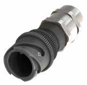
Dimension “L” can be different from the value indicated according to backshells accessories, wires size and some special insert configurations.
150 Go online for data sheets & assembly instructions. Visit www.radiall.com/vansystem and enter the part number. CVBS SHELL
L ØB N K M ØD ØQ Shell size ØD +0 -0.15 ØQ Max ØB ±0.2 L max K ±0.2 M ±0.2 Backshell Metric Thread ØN Clamping range 10SL 18.2 22 20 87 2.8 14.2 M12 3.5-7 14S 24.6 29 24 93 3.2 14.5 M16 4.5-10 16S 27.4 31 27 96.5 3.2 14.2 M20 7-13 16 27.4 31 27 103.5 3.2 19 M20 7-13 18 30.8 34 30 103.5 4 19 M20 7-13 20 34.2 37 32 104.5 4 19 M25 9-17 22 37.4 40 37 110.5 4 19.7 M32 11-21 24 40.9 44 40 112.5 4 20.6 M32 11-21 28 46.7 49.5 45 122.5 4 20.6 M32 11-21 32 53.4 56 52 127 4 22.2 M40 19-28 36 59.6 62.5 58 132 4 22.2 M40 19-28 40 65.5 68.5 63.2 138 4 22.2 M40 19-28
in mm IP67
Dimensions
CVBS - Bayonet Connector with protected mating ramps
Shell Material Backshell internal thread
Grommet (RA..MH RA..PH Class only)
Grommet cone (RA..MH RA..PH Class only)
Chloroprene
RF Insulating material
Backshell
Provided with a Metric thread Cable Glands PH Provided with a PG thread Cable Glands*** CR Contact Termination
CD5 Contact Plating
- Solder contacts
CR Crimp contacts
LC Less contacts
Silver plating
CD5 Gold plating
F5 Electroless nickel (*)
F7 Black epoxy varnish (*)
F16 CCF - Black passivation (*) - conductive
F26 hard anodization (*)
151 Go online for data sheets & assembly instructions. Visit www.radiall.com/vansystem and enter the part number.
SHELL
Shell finish
CVBS
Series Code Shell Type Connector Class
(*)
compliance
RF CVBS 01DAT 20-27SX MH12 CR CD5 F7 N RF CVBS 01 DA 20-27 S X MH12 CR CD5 F7 N T
RoHS
P/N Sample:
Gasket
(**) If required *** Consult our sales office
CVBS Series Code CVBS
Shell Material - Aluminum 01 Shell Type 01 In-line receptacle DA
DA
O-ring
RA
T
Size
Type
S
P
MH
Metal Cable Glands
-
rubber V Fluoride rubber S Silicone rubber RF Fire resistant rubber
Bayonet Connector with protected mating ramps
Connector Class
with waterproof
(IP67)
with waterproof O-ring and grommet (IP67) T Connector Modification**
With plastic caps 20-27 Insert Arrangement
-
S Contact Gender
Socket contacts
Pin contacts X Polarization Code** Alternate Positions MH12 Backshell internal thread
-
F7 Shell finish
N
N
S
Modification Code**
Consult our sales office
- Bayonet Connector with protected mating
In-Line Receptacle (01) with Backshell Class (AR - R)
This class is suitable to connect single wires when strain relief is not necessary and small longitudinal overall dimensions are needed. As watertightness is guaranteed by the grommet only, it is necessary to make sure the wire diameter matches the grommet sealing range.
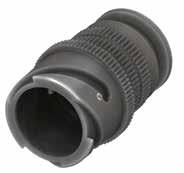
Dimensions in mm
Dimension “L” can be different from the value indicated according to backshells accessories, wires size and some special insert configurations.
152 Go online for data sheets & assembly instructions. Visit www.radiall.com/vansystem and enter the part number. CVBS SHELL CVBS
L ØB N K M ØD ØQ Shell size ØD +0 -0.15 ØQ Max ØB ±0.2 L K ±0.2 M ±0.2 N max cable dimension 10SL 18.2 22 20 41 2.8 14.2 10 14S 24.6 29 24 42 3.2 14.5 13.5 16S 27.4 31 27 42 3.2 14.2 16.1 16 27.4 31 27 49 3.2 19 16.5 18 30.8 34 30 50 4 19 19 20 34.2 37 32 50 4 19 22.2 22 37.4 40 37 53 4 19.7 24.5 24 40.9 44 40 53 4 20.6 28 28 46.7 49.5 45 61 4 20.6 32.6 32 53.4 56 52 62 4 22.2 38 36 59.6 62.5 58 62 4 22.2 45 40 65.5 68.5 63.2 62 4 22.2 51.3
ramps
CVBS - Bayonet Connector with protected mating ramps
The accessories for this class are not always available in stock for all sizes; we suggest you consult our Sales Office for availability
RF Insulating material - Chloroprene rubber
Fluoride rubber
Silicone rubber
Fire resistant rubber
S Contact Gender S Socket contacts P Pin contacts X Polarization Code** Alternate Positions CR Contact Termination - Solder contacts CR Crimp contacts LC Less contacts
CD5 Contact Plating - Silver plating
CD5 Gold plating
F5 Electroless nickel (*)
F7 Black epoxy varnish (*)
F16 CCF - Black passivation (*) - conductive
F26 hard anodization (*)
If
153 Go online for data sheets & assembly instructions. Visit www.radiall.com/vansystem and enter the part number.
SHELL ØB
CVBS
Backshell Grommet
Grommet
Gasket
Shell
cone (R Class only)
(R Class only)
(R Class only) Series Code Shell Type Connector Class
finish
(*) RoHS compliance P/N Sample: RF CVBS 01RT 20-27SX CR CD5 F7 N RF CVBS 01 R 20-27 S X CR CD5 F7 N T Shell
(**)
CVBS
Code CVBS Bayonet
- Aluminum 01 Shell Type 01 In-line receptacle R
AR non watertight R with waterproof O-ring and grommet
T
20-27
Size - Type
Material
required
V
S
RF
Series
Connector with protected mating ramps Shell Material
Connector Class
T Connector Modification**
With plastic caps
Insert Arrangement
F7
Shell finish
N
N
our sales
S
Modification Code**
Consult
office
- Bayonet Connector with protected mating ramps In-Line Receptacle (01) with Backshell Class (AG - G)
These classes of connectors are all suitable for heat shrink tubing applications.
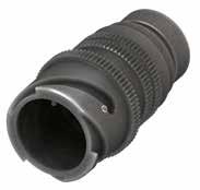
Dimensions
Dimension “L” can be different from the value indicated according to backshells accessories, wires size and some special insert configurations.
154 Go online for data sheets & assembly instructions. Visit www.radiall.com/vansystem and enter the part number. CVBS SHELL
L ØD3 L1 L2 ØD2 ØB ØD1 ØD4 K M ØD ØQ Shell size ØD +0 -0.15 ØQ Max ØB ±0.2 ØD1 ±0.2 ØD2 ±0.2 ØD3 ±0.2 ØD4 ±0.2 L L1 ±0.2 L2 ±0.2 K ±0.2 M ±0.2 10SL 18.2 22 20 17 15.5 13.3 7.9 48 11.7 3.5 2.8 14.2 14S 24.6 29 24 20.1 19.1 17 13.5 48 11.7 3.5 3.2 14.5 16S 27.4 31 27 23.5 23.9 21.9 13.7 48 11.7 3.5 3.2 14.2 16 27.4 31 27 23.5 23.9 21.9 16.1 60 11.5 3.5 3.2 19 18 30.8 34 30 26.5 23.9 21.9 19 65 11.5 3.5 4 19 20 34.2 37 32 30.2 29.6 26.2 22.2 65 12.4 3.5 4 19 22 37.4 40 37 33.6 29.6 26.2 22 65 12.7 3.5 4 19.7 24 40.9 44 40 36.1 37.8 34.5 28 65 12.7 3.5 4 20.6 28 46.7 49.5 45 41.4 37.8 34.5 29 65 12.7 3.5 4 20.6 32 53.4 56 52 50 47.8 43.4 35.2 70 15.2 3.5 4 22.2 36 59.6 62.5 58 56 47.7 43.4 40 75 15.2 3.5 4 22.2 40 65.5 68.5 63.2 62.4 57.6 52.4 48 77 15.2 3.5 4 22.2
CVBS
in mm
CVBS - Bayonet Connector with protected mating ramps
Grommet cone (G Class only)
The accessories for this class are not always available in stock for all sizes; we suggest you consult our Sales Office for availability Backshell
RF Insulating material - Chloroprene rubber V Fluoride rubber
AG Connector Class AG with waterproof O-ring (IP67***) G with waterproof O-ring and grommet (IP67***)
T Connector Modification** T With plastic caps
20-27 Insert Arrangement Size - Type
Grommet (G Class only) Gasket (*) RoHS compliance (**) If required *** Protection degree: IP 67 (only in the mating area with mated connectors) according to EN 60529
P/N
S Contact Gender S Socket contacts
P Pin contacts
X Polarization Code** Alternate Positions
CR Contact Termination - Solder contacts
CR Crimp contacts
LC Less contacts
CD5 Contact Plating - Silver plating
F7 Shell finish
CD5 Gold plating
F5 Electroless nickel (*)
F7 Black epoxy varnish (*)
F16
CCF - Black passivation (*) - conductive
F26 hard anodization (*)
N Modification Code** N
Consult our sales office S
155 Go online for data sheets & assembly instructions. Visit www.radiall.com/vansystem and enter the part number.
SHELL
CVBS
Series Code Shell Type Connector Class Shell finish
RF CVBS 01 AG 20-27 S X CR CD5 F7 N T Shell
ØD3 L1 L2 ØD2 ØB ØD1 ØD4
Sample: RF CVBS 01AGT 20-27SX CR CD5 F7 N
Material
S Silicone rubber RF Fire resistant rubber
CVBS
- Aluminum 01 Shell Type 01 In-line receptacle
CVBS Series Code
Bayonet Connector with protected mating ramps Shell Material
- Bayonet Connector with protected mating ramps In-Line Receptacle (01) with Backshell Class (AG2 - G2)
These classes of connectors are all suitable for heat shrink tubing applications. Two piece backshell includes nut for shell tightening. Internal serration prevents backshell rotation and allows easy assembling after contacts are inserted.
Dimension “L” can be different from the value indicated according to backshells accessories, wires size and some special insert configurations.
156 Go online for data sheets & assembly instructions. Visit www.radiall.com/vansystem and enter the part number. CVBS SHELL CVBS
Shell size ØD +0 -0.15 ØQ Max ØB ±0.2 ØD1 ±0.2 ØD2 ±0.2 ØD3 ±0.2 ØD4 ±0.2 L L1 ±0.2 L2 ±0.2 K ±0.2 M ±0.2 10SL 18.2 22 22.5 17 15.5 13.3 8.6 48 11.7 3.5 2.8 14.2 14S 24.6 29 26 20.1 19.1 17 10.8 48 11.7 3.5 3.2 14.5 16S 27.4 31 29 23.5 23.9 21.9 14 48 11.7 3.5 3.2 14.2 16 27.4 31 29 23.5 23.9 21.9 14 60 11.5 3.5 3.2 19 18 30.8 34 33.4 26.5 23.9 21.9 14.8 65 11.5 3.5 4 19 20 34.2 37 37 30.2 29.6 26.2 19.3 65 12.4 3.5 4 19 22 37.4 40 41 33.6 29.6 26.2 22.5 65 12.7 3.5 4 19.7 24 40.9 44 45.9 36.1 37.8 34.5 28 65 12.7 3.5 4 20.6 28 46.7 49.5 51 41.4 37.8 34.5 28 65 12.7 3.5 4 20.6 32 53.4 56 58 50 47.8 43.4 34.8 70 15.2 3.5 4 22.2 36 59.6 62.5 60.5 56 47.7 43.4 38.7 75 15.2 3.5 4 22.2 40 65.5 68.5 69 62.4 57.6 52.4 48.2 77 15.2 3.5 4 22.2 M L ØD1 ØD3 ØB L1 L2 ØD2 ØD4 K ØD ØQ
Dimensions in mm
CVBS - Bayonet Connector with protected mating ramps
The accessories for this class are not always available in stock for all sizes; we suggest you consult our Sales Office for availability
With waterproof O-ring (IP67***)
With waterproof O-ring and grommet (IP67***)# T Connector Modification** T With plastic caps
Insert Arrangement Size - Type
Contact Gender
Socket contacts P Pin contacts
Polarization Code** Alternate Positions
Contact Termination - Solder contacts CR Crimp contacts LC Less contacts CD5 Contact Plating - Silver plating
CD5 Gold plating
F5 Electroless nickel (*) F7 Black epoxy varnish (*)
F16
CCF - Black passivation (*) - conductive F26 hard anodization (*)
Consult our sales office
157 Go online for data sheets & assembly instructions. Visit www.radiall.com/vansystem and enter the part number. CVBS SHELL
G2
Series Code Shell Type Connector Class Shell finish
Backshell Grommet cone (G2 Class only) Grommet (G2 Class only) Gasket P/N
RF CVBS 01G2T 20-27SX CR CD5 F7 N RF CVBS 01 G2 20-27 S X CR CD5 F7 N T Shell Material (*)
***
Nut
V
S
RF
CVBS
Shell Material - Aluminum 01 Shell Type 01 In-line receptacle
AG2
Sample:
RoHS compliance (**) If required
Protection degree: IP 67 (only in the mating area with mated connectors) according to EN 60529
RF Insulating material - Chloroprene rubber
Fluoride rubber
Silicone rubber
Fire resistant rubber CVBS Series Code
Bayonet Connector with protected mating ramps
G2 Connector Class
G2
20-27
S
S
X
CR
F7
finish
Shell
N
S
N Modification Code**
(#) In some sizes the grommet cone is not needed
CVBS - Bayonet Connector with protected mating ramps
In-Line Receptacle (01) with Backshell Class (ASB1 - SB1)
Backshell for multicore jacketed shielded cables, provided with MS 3057…C type Cable-Clamp. (for jacketed cable) Also available versions for over/under dimensioned cables.
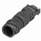
Dimensions
Dimension “L” can be different from the value indicated according to backshells accessories, wires size and some special insert configurations.
158 Go online for data sheets & assembly instructions. Visit www.radiall.com/vansystem and enter the part number. CVBS SHELL
K M Ø D L ØB A Ø F ØQ Shell size ØD +0 -0.15 ØQ Max ØB ±0.2 K ±0.2 L M ±0.2 A ±0.2 ØF cable dimension Min Max 10SL 18.2 22 20 2.8 99 14.2 23 2.4 7.9 14S 24.6 29 24 3.2 99 14.5 26 5.8 11.2 16S 27.4 31 27 3.2 100 14.2 28.5 8 13.5 16 27.4 31 27 3.2 118 19 28.5 8 13.5 18 30.8 34 32 4 124 19 32 9.6 15.9 20 34.2 37 35 4 124 19 37.5 11.3 19 22 37.4 40 37 4 124 19.7 37.5 11.3 19 24 40.9 44 42 4 135 20.6 43.5 15.5 23.8 28 46.7 49.5 45 4 138 20.6 43.5 15.5 23.8 32 53.4 56 50 4 146 22.2 54 23.4 31.8 36 59.6 62.5 58 4 150 22.2 58 25.4 35 40 65.5 68.5 63.8 4 154 22.2 63.5 30 41.3
in mm IP67
CVBS - Bayonet Connector with protected mating ramps
Contact Termination - Solder contacts
Crimp contacts LC Less contacts
varnish (*) F16 CCF - Black passivation
anodization (*)
Insert Arrangement
159 Go online for data sheets & assembly instructions. Visit www.radiall.com/vansystem and enter the part number.
SHELL
CVBS
Backshell Grommet
Gasket (*) RoHS compliance P/N Sample: RF CVBS 01SB1T 20-27SX CR CD5 F7 N
MS3057...C Series Code Shell Type Connector Class Shell finish RF CVBS 01 ASB1 20-27 S X CR CD5 F7 N T Shell Material (**) If required
are not always
stock for all sizes; we suggest you consult our Sales
for availability Shielding Ring Backshell Gasket RF
- Chloroprene rubber V Fluoride rubber S Silicone rubber RF Fire resistant rubber CVBS Series Code CVBS Bayonet Connector with protected mating ramps Shell Material - Aluminum 01 Shell Type 01 In-line receptacle ASB1
Class ASB1 with waterproof O-ring (IP67) SB1 with waterproof O-ring and grommet (IP67)# T
T With plastic caps 20-27
Size - Type S Contact Gender S
P
X
CR
CD5
-
F7 Shell finish
N
Code** N
our
S (#)
needed
cone (SB1 Class only) Grommet (SB1 Class only)
Cable-Clamp
The accessories for this class
available in
Office
Insulating material
Connector
Connector Modification**
Socket contacts
Pin contacts
Polarization Code** Alternate Positions
CR
Contact Plating
Silver plating CD5 Gold plating
F5 Electroless nickel (*) F7 Black epoxy
(*) - conductive F26 hard
Modification
Consult
sales office
In some sizes the grommet cone is not
CVBS - Bayonet Connector with protected mating ramps
In-Line Receptacle (01) with Backshell Class (AGV - GV)
These classes of connectors are provided with backshell for shield hose and heat shrink tubing termination. It comes complete with conical protection spring, also suitable for thin shield braid.
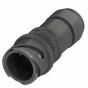
Dimensions in mm
Dimension “L” can be different from the value indicated according to backshells accessories, wires size and some special insert configurations.
160 Go online for data sheets & assembly instructions. Visit www.radiall.com/vansystem and enter the part number. CVBS SHELL
K M D L ØB Ø D1 Ø D2 ØD3 L2 3.5 ØQ Shell size ØD +0 -0.15 ØQ Max ØB ±0.2 ØD1 ±0.2 ØD2 ±0.2 ØD3 ±0.2 L L2 ±0.2 K ±0.2 M ±0.2 10SL 18.2 22 20 8.6 18.5 16.3 65 18 2.8 14.2 14S 24.6 29 24 10.6 22 20 65 17.6 3.2 14.5 16S 27.4 31 27 10.4 25 23 65 20.7 3.2 14.2 16 27.4 31 27 13.5 25 23 74 20.8 3.2 19 18 30.8 34 30 14.5 28 24.5 75 20.8 4 19 20 34.2 37 32 18.4 32 28.5 75 20.8 4 19 22 37.4 40 37 20.7 34 30.5 75 20.8 4 19.7 24 40.9 44 40 24.6 38.5 34.5 81 20.7 4 20.6 28 46.7 49.5 46 25 40 36 81 21.8 4 20.6 32 53.4 56 52 33.3 48 44 83 20.7 4 22.2 36 59.6 62.5 58 38.5 55 51 83 20.7 4 22.2 40 65.5 68.5 63.8 46 62 58 83 21.8 4 22.2
CVBS - Bayonet Connector with protected mating ramps
The accessories for this class are not always available in stock for all sizes; we suggest you consult our Sales Office for availability
T Connector Modification** T With plastic caps 20-27 Insert Arrangement Size - Type
Contact Gender S Socket contacts P Pin contacts X Polarization Code** Alternate Positions CR Contact Termination
- Solder contacts CR Crimp contacts
LC Less contacts
CD5 Contact Plating - Silver plating
CD5 Gold plating
F5 Electroless nickel (*) F7 Black epoxy varnish (*)
F16 CCF - Black passivation (*) - conductive F26 hard anodization (*)
161 Go online for data sheets & assembly instructions. Visit www.radiall.com/vansystem and enter the part number.
SHELL
Type
Shell finish
CVBS
Series Code Shell
Connector Class
RF CVBS 01GVT 20-27SX CR CD5 F7 N RF CVBS 01 GV 20-27 S X CR CD5 F7 N T Shell Material (*) RoHS compliance (**) If required *** Protection degree: IP 67
mating area
mated connectors) according to EN 60529 GV
Gasket Rear Nut Conical Ring Grommet cone
Series Code CVBS
mating
Shell Material - Aluminum 01 Shell Type 01 In-line receptacle
P/N Sample:
(only in the
with
Backshell
(GV Class only) Grommet (GV Class only) RF Insulating material - Chloroprene rubber V Fluoride rubber S Silicone rubber RF Fire resistant rubber CVBS
Bayonet Connector with protected
ramps
GV Connector Class AGV With waterproof O-ring (IP67***) GV with waterproof O-ring and grommet (IP67***)
S
F7 Shell finish
N Modification Code** N Consult our sales office S
- Bayonet Connector with protected mating ramps
In-Line Receptacle (01) with Backshell Class (SB)
These classes of connectors are provided with backshell for shield hose and heat shrink tubing termination. It comes complete with conical protection spring, also suitable for thin shield braid. Two piece backshell includes nut for shell tightening. Internal serration prevents backshell rotation and allows easy assembling after contacts are inserted.
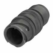
Dimensions in mm
Dimension “L” can be different from the value indicated according to backshells accessories, wires size and some special insert configurations.
162 Go online for data sheets & assembly instructions. Visit www.radiall.com/vansystem and enter the part number. CVBS SHELL
CVBS
K M Ø D L ØB Ø D1 Ø D2 ØD3 L2 3.5 ØQ Shell size ØD +0 -0.15 ØQ Max ØB ±0.2 ØD1 ±0.2 ØD2 ±0.2 ØD3 ±0.2 L L2 ±0.2 K ±0.2 M ±0.2 10SL 18.2 22 22.5 8.6 18.5 16.3 60 18 2.8 14.2 14S 24.6 29 26.1 10.6 22 20 60 17.6 3.2 14.5 16S 27.4 31 29 10.4 25 23 60 20.7 3.2 14.2 16 27.4 31 29 13.5 25 23 65 20.8 3.2 19 18 30.8 34 33.5 14.5 28 24.5 69 20.8 4 19 20 34.2 37 37 18.4 32 28.5 70 20.8 4 19 22 37.4 40 41 20.7 34 30.5 70 20.8 4 19.7 24 40.9 44 46 24.6 38.5 34.5 73 20.7 4 20.6 28 46.7 49.5 51 25 40 36 74 21.8 4 20.6 32 53.4 56 58 33.3 48 44 75 20.7 4 22.2 36 59.6 62.5 61 38.5 55 51 75 20.7 4 22.2 40 65.5 68.5 69 46 62 58 75 21.8 4 22.2
CVBS - Bayonet Connector with protected mating ramps
RF Insulating material - Chloroprene rubber
resistant
The accessories for this class are not always available in stock for all sizes; we suggest you consult our Sales Office for availability P/N Sample:
SB Connector Class
S Contact Gender
Socket contacts P Pin contacts X Polarization Code** Alternate Positions CR Contact Termination - Solder contacts CR Crimp contacts
LC Less contacts
CD5 Contact Plating - Silver plating
CD5 Gold plating
F5 Electroless nickel (*)
F7 Black epoxy varnish (*)
F16 CCF - Black passivation (*) - conductive
F26 hard anodization (*)
Consult our sales office
(#) In some sizes the grommet cone is not needed
163 Go online for data sheets & assembly instructions. Visit www.radiall.com/vansystem and enter the part number.
SHELL
Shell
CVBS
Series Code Shell Type Connector Class
finish
RF CVBS 01SBT 20-27SX CR CD5 F7 N RF CVBS 01 SB 20-27 S X CR CD5 F7 N T Shell Material (*)
***
GV Two piece backshell Gasket Rear Nut Conical Ring Grommet cone Grommet
V
Shell
- Aluminum 01 Shell Type 01 In-line receptacle
RoHS compliance (**) If required
Protection degree: IP 67 (only in the mating area with mated connectors) according to EN 60529
Fluoride rubber S Silicone rubber RF Fire
rubber CVBS Series Code CVBS Bayonet Connector with protected mating ramps
Material
SB
20-27
Size
Type
With waterproof O-ring and grommet (IP67***)# T Connector Modification** T With plastic caps
Insert Arrangement
-
S
F7
Shell finish
N
N
S
Modification Code**
CVBS - Bayonet Connector with protected mating ramps
Rear Mounting Receptacle (07/07R) unable to accept Rear Accessories
Mounting is made by a hexagonal coupling nut. It is supplied with sealing gasket to guarantee waterproof protection. ** On request (please consult our Sales Office)
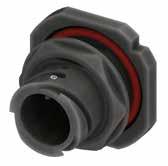
required the nut can be lock with optional screws
164 Go online for data sheets & assembly instructions. Visit www.radiall.com/vansystem and enter the part number. CVBS SHELL Dimension
can be different from the value indicated according to backshells accessories, wires size
some special insert configurations. Dimensions in mm Panel cut out K M ØD P R S T T L ØC A Shell size ØD K ±0.1 M ±0.2 L R ±0.1 S ±0.25 T ±0.1 P Panel Thickness ØC - 0 + 0.25 A ±0.2 Min Max 10SL** 18.2 4 24.5 28.5 27 31.8 11.2 2.4 5.2 22.4 21 14S 24.6 4.8 26.8 31.6 33 41.3 14.6 2.4 7.5 28.75 27.4 16S 27.4 4.8 26.8 31.6 38 44.4 15.7 2.4 7.5 31.95 30.95 16** 27.4 4.8 32.1 36.9 38 44.4 15.7 2.4 7.5 31.95 30.95 18 30.8 4.8 33.7 38.5 39.7 47.6 16.8 2.4 9 35.1 33.75 20 34.2 4.8 33.7 38.5 44 50.8 18 2.4 8.1 38.3 36.85 22 37.4 4.8 33.7 38.5 46 54.2 20.2 2.4 9.1 41.45 40.05 24 40.9 4.8 33.7 38.5 50.8 57.2 20.2 2.4 9.1 44.65 43.35 28 46.7 5.6 35.2 40.8 55 63.5 22.5 2.4 8.5 51 49.55 32 53.4 5.6 35.2 40.8 62 69.8 24.7 2.4 6.5 57.35 55.95 36 59.6 5.6 35.2 40.8 71 76.2 26.9 2.4 8.3 63.7 62.35 40 65.5 5.6 35.2 40.8 75 83.5 29.6 2.4 8.3 70.05 68.55
“L”
and
If
CVBS - Bayonet Connector with protected mating ramps
RF Insulating material - Chloroprene rubber
V Fluoride rubber
S Silicone rubber
RF Fire resistant rubber CVBS
Rear mounting Receptacle, unable to accept rear accessories. Mounting is made by a hexagonal coupling nut. It is supplied with sealing gasket to guarantee waterproof protection.
Rear mounting Receptacle connector enviromental seal, unable to accept rear accessories. Mounting is made by a hexagonal coupling nut. It is supplied with sealing gasket to guarantee waterproof protection.
T Connector Modification** T With plastic caps 20-27 Insert Arrangement
S Contact Gender
Socket contacts
contacts
CR Contact Termination - Solder contacts
CD5 Contact Plating
F7 Shell finish
N Modification Code**
CR Crimp contacts
LC Less contacts
- Silver plating
CD5 Gold plating
F5 Electroless nickel (*)
F7 Black epoxy varnish (*)
F16 CCF - Black passivation (*) - conductive
F26 hard anodization (*)
165 Go online for data sheets & assembly instructions. Visit www.radiall.com/vansystem and enter the part number.
SHELL
Shell Type Shell finish
CVBS
Series Code
(*) RoHS compliance
Sample: RF CVBS 07T 20-27SX CR CD5 F7 N RF CVBS 07 20-27 S X CR CD5 F7 N T Shell
(**) If required
P/N
Material
Series Code
Bayonet Connector with protected mating ramps Shell Material - Aluminum 07 Shell Type 07
CVBS
07R
Size
Type
-
S
P Pin
X Polarization Code** Alternate Positions
S
N Consult our sales office
CVBS - Bayonet Connector with protected mating ramps
Rear Mounting Receptacle (070) without Accessories (To be purchased separately)
Mounting is made by a hexagonal coupling nut. It is supplied with sealing gasket to guarantee waterproof protection. ** On request (please consult our Sales Office)
If required the nut can be lock with optional screws
166 Go online for data sheets & assembly instructions. Visit www.radiall.com/vansystem and enter the part number. CVBS SHELL Dimension “L” can be different from the value indicated according to backshells accessories, wires size and some special insert configurations. Dimensions in mm Panel cut out K M ØD P R S T T L ØN ØC A Shell size ØD K ±0.1 M ±0.2 L N Backshell Thread in inches R ±0.1 S ±0.25 T ±0.1 P Panel Thickness ØC - 0 + 0.25 A ±0.2 Min Max 10SL** 18.2 4 24.5 36.2 5/8”-24 UNEF 27 31.8 11.2 2.4 5.2 22.4 21 14S 24.6 4.8 26.8 39.8 3/4”-20 UNEF 33 41.3 14.6 2.4 7.5 28.75 27.4 16S 27.4 4.8 26.8 40.1 7/8”-20 UNEF 38 44.4 15.7 2.4 7.5 31.95 30.95 16** 27.4 4.8 32.1 48.9 7/8”-20 UNEF 38 44.4 15.7 2.4 7.5 31.95 30.95 18 30.8 4.8 33.7 49.3 1”-20 UNEF 39.7 47.6 16.8 2.4 9 35.1 33.75 20 34.2 4.8 33.7 50.2 1” 1/8-18 UNEF 44 50.8 18 2.4 8.1 38.3 36.85 22 37.4 4.8 33.7 50.5 1” 1/4-18 UNEF 46 54.2 20.2 2.4 9.1 41.45 40.05 24 40.9 4.8 33.7 49.3 1” 3/8-18 UNEF 50.8 57.2 20.2 2.4 9.1 44.65 43.35 28 46.7 5.6 35.2 51.9 1” 5/8-18 UNEF 55 63.5 22.5 2.4 8.5 51 49.55 32 53.4 5.6 35.2 51.9 1” 7/8-16 UN 62 69.8 24.7 2.4 6.5 57.35 55.95 36 59.6 5.6 35.2 51.9 2” 1/16-16 UN 71 76.2 26.9 2.4 8.3 63.7 62.35 40 65.5 5.6 35.2 51.9 2” 5/16-16 UNS 75 83.5 29.6 2.4 8.3 70.05 68.55
CVBS - Bayonet Connector with protected mating ramps
RF Insulating material
CVBS Series Code
CVBS Bayonet Connector with protected mating ramps
Shell Material - Aluminum
070 Shell Type 070
Rear mounting Receptacle, without accessories. Mounting is made by a hexagonal coupling nut. It is supplied with sealing gasket to guarantee waterproof protection. T Connector Modification** T With plastic caps
20-27 Insert Arrangement Size - Type S Contact Gender
Pin contacts X Polarization Code** Alternate Positions CR Contact Termination
Solder contacts
Crimp contacts
Less contacts
Silver plating
CD5 Contact Plating
F7 Shell finish
CD5 Gold plating
F5 Electroless nickel (*)
F7 Black epoxy varnish (*)
F16 CCF - Black passivation (*) - conductive
F26 hard anodization (*)
N Modification Code** N Consult our sales office
167 Go online for data sheets & assembly instructions. Visit www.radiall.com/vansystem and enter the part number.
SHELL
CVBS
Series Code Shell Type Shell finish
(*)
RF CVBS 070T 20-27SX CR CD5 F7 N RF CVBS 070 20-27 S X CR CD5 F7 N T
(**)
required
-
V
S
RF
RoHS compliance P/N Sample:
Shell Material
If
Chloroprene rubber
Fluoride rubber
Silicone rubber
Fire resistant rubber
S
P
-
CR
Socket contacts
LC
-
S
CVBS - Bayonet Connector with protected mating ramps
Plug Connector (06) with Backshell Class (A - DA - RA)
Connector with backshell provided with an external thread suitable for MS3057…A or C type Cable-Clamps (to be ordered separately).
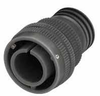
Dimensions in mm
Dimension “L” can be different from the value indicated according to backshells accessories, wires size and some special insert configurations.
168 Go online for data sheets & assembly instructions. Visit www.radiall.com/vansystem and enter the part number. CVBS SHELL
L ØB N ØQ Shell size ØQ ±0.2 ØB ±0.2 L max N Backshell Thread in inches 10SL 23.3 20 36 5/8”-24 UNEF 14S 29.5 24 43 3/4”-20 UNEF 16S 33 27 43 7/8”-20 UNEF 16 33 27 49 7/8”-20 UNEF 18 37 30 52 1”-20 UNEF 20 41 32 52.5 1” 3/16-18 UNEF 22 43 37 55 1” 3/16-18 UNEF 24 48 40 55 1” 7/16-18 UNEF 28 53 45 62 1” 7/16-18 UNEF 32 60 52 62 1” 3/4-18 UNS 36 66.2 58 62 2”-18 UNS 40 72.4 63.8 64 2”1/4-16 UN
CVBS - Bayonet Connector with protected mating ramps
Grommet cone (RA Class only) Grommet (RA Class only)
RF Insulating material - Chloroprene rubber V Fluoride rubber S Silicone rubber RF Fire resistant rubber CVBS Series Code
(DA-RA Class only)
Connector Class
Connector
with waterproof O-ring (IP67***)
with waterproof O-ring and grommet (IP67***)
S Contact Gender S Socket contacts P Pin contacts X Polarization Code** Alternate Positions
CR Contact Termination - Solder contacts
CR Crimp contacts
LC Less contacts
CD5 Contact Plating - Silver plating
CD5 Gold plating
F5 Electroless nickel (*)
F7 Black epoxy varnish (*)
F16
CCF - Black passivation (*) - conductive
F26 hard anodization (*) N Modification Code**
Consult our sales office
169 Go online for data sheets & assembly instructions. Visit www.radiall.com/vansystem and enter the part number.
SHELL
CVBS
Shell finish RF CVBS 06 DA 20-27 S X CR CD5 F7 N T Shell Material ØB N
P/N Sample: RF CVBS 06DAT 20-27SX CR CD5 F7 N Series Code Shell Type Connector Class
Backshell
Gasket
(*)
RoHS compliance (**) If required *** Protection degree: IP 67 (only in the mating area with mated connectors) according to EN 60529
06
06
A
DA
RA
CVBS Bayonet Connector with protected mating ramps Shell Material - Aluminum
Shell Type
Plug Connector DA
non watertight
T
Modification** T With plastic caps 20-27 Insert Arrangement Size - Type
F7
Shell finish
N
S
CVBS - Bayonet Connector with protected mating ramps
Plug Connector (06) with Backshell Class (LA - LDA - LRA)
Connector with Llong backshell provided with an external thread suitable for MS3057…A or C type Cable-Clamps (to be ordered separately).
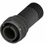
“L”
170 Go online for data sheets & assembly instructions. Visit www.radiall.com/vansystem and enter the part number. CVBS SHELL
L ØQ ØB N Shell size ØQ ±0.2 ØB ±0.2 L max N Backshell Thread in inches 10SL 23.3 20 68 5/8”-24 UNEF 14S 29.5 24 68 3/4”-20 UNEF 16S 33 27 68 7/8”-20 UNEF 16 33 27 78.5 7/8”-20 UNEF 18 37 30 78.5 1”-20 UNEF 20 41 32 79 1” 3/16-18 UNEF 22 43 37 80.5 1” 3/16-18 UNEF 24 48 40 81 1” 7/16-18 UNEF 28 53 45 81 1” 7/16-18 UNEF 32 60 52 95.5 1” 3/4-18 UNS 36 66.2 58 95.5 2”-18 UNS 40 72.4 63.8 96.5 2”1/4-16 UN
special insert
Dimension
can be different from the value indicated according to backshells accessories, wires size and some
configurations.
Dimensions in mm
CVBS - Bayonet Connector with protected mating ramps
RF Insulating material - Chloroprene rubber V Fluoride rubber S Silicone rubber RF Fire resistant rubber CVBS Series Code CVBS Bayonet Connector with protected mating ramps
S Contact Gender S Socket contacts P Pin contacts
X Polarization Code** Alternate Positions
CR Contact Termination
LDA Connector Class LA non watertight LDA with waterproof O-ring (IP67***) LRA with waterproof O-ring and grommet (IP67***)
T Connector Modification** T With plastic caps 20-27 Insert Arrangement Size - Type
P/N
- Solder contacts
CR Crimp contacts
LC Less contacts
CD5 Contact Plating - Silver plating
CD5 Gold plating
F5 Electroless nickel (*)
F7 Black epoxy varnish (*)
F16 CCF - Black passivation (*) - conductive
F26 hard anodization (*) N Modification Code**
Consult our sales office
171 Go online for data sheets & assembly
Visit www.radiall.com/vansystem and enter the part number.
SHELL
instructions.
CVBS
Shell finish RF CVBS 06 LDA 20-27 S X CR CD5 F7 N T Shell Material ØB N
Sample: RF CVBS 06LDAT 20-27SX CR CD5 F7 N Series Code Shell Type Connector Class
Gasket
Backshell
Grommet cone (LRA Class only) Grommet (LRA Class only)
(LDA-LRA Class only) (*) RoHS compliance (**) If required *** Protection degree: IP 67 (only in the mating area with mated connectors) according to EN 60529
Shell Material - Aluminum 06 Shell Type 06 Plug Connector
F7 Shell finish
N
S
CVBS - Bayonet Connector with protected mating ramps
Plug Connector (06) with Backshell Class (AF - F)
Connector provided with backshell, MS3057...A type Cable-Clamp and bushing MS3420... (for single wire)
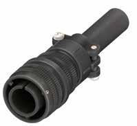
Dimension “L” can be different from the value indicated according to backshells accessories, wires size and some special insert configurations.
172 Go online for data sheets
Visit www.radiall.com/vansystem and enter the part number. CVBS SHELL
& assembly instructions.
ØQ L ØB A F Ø Shell size ØQ ±0.2 L max ØB ±0.2 A max ØF cable max dimension 10SL 23.3 46 20 22.5 5.6 14S 29.5 55 24 28 7.9 16S 33 56.5 27 30 11 16 33 62.5 27 30 11 18 37 67.5 30 31.7 14.2 20 41 68 32 37.5 15.8 22 43 70.5 37 37.5 15.8 24 48 70.5 40 43.5 19 28 53 77.5 45 43.5 19 32 60 77.5 52 51.7 23.8 36 66.2 77.5 58 58.5 31.7 40 72.4 93 63.8 68.5 34.9
in mm IP54
Dimensions
CVBS - Bayonet Connector with protected mating ramps
RF Insulating material - Chloroprene rubber V Fluoride rubber S Silicone rubber RF Fire resistant rubber
Contact Termination
- Solder contacts CR Crimp contacts
LC Less contacts
CD5 Contact Plating - Silver plating
CD5 Gold plating
F5 Electroless nickel (*)
F7 Black epoxy varnish (*)
F16 CCF - Black passivation (*) - conductive
F26 hard anodization (*)
If
173 Go online for data sheets & assembly instructions. Visit www.radiall.com/vansystem and enter the part number.
SHELL
CVBS
(*)
RF CVBS 06AFT 20-27SX CR CD5 F7 N
Type
Class Shell finish RF CVBS 06 AF 20-27 S X CR CD5 F7 N T Shell
Gasket H A F Ø ØB ØB A F Ø
CVBS Series Code CVBS
Shell Material - Aluminum 06 Shell Type 06 Plug Connector
AF
F
T
Size - Type S
S
RoHS compliance P/N Sample:
Series Code Shell
Connector
Material Backshell Grommet cone (F Class only) Grommet (F Class only)
Cable-Clamp MS3057...A bushing MS3420 (**)
required
Bayonet Connector with protected mating ramps
AF Connector Class
with waterproof O-ring (IP54)
with waterproof O-ring and grommet (IP54) T Connector Modification**
With plastic caps 20-27 Insert Arrangement
Contact Gender
Socket contacts P Pin contacts X Polarization Code** Alternate Positions CR
F7 Shell finish
N
N
S
Modification Code**
Consult our sales office
CVBS - Bayonet Connector with protected mating ramps
Plug Connector (06) with Backshell Class (LAF - LF)
Connector provided with long backshell, MS3057...A type Cable-Clamp and bushing MS3420... (for single wire)
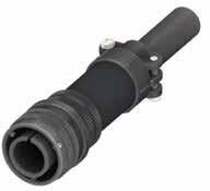
Dimension “L” can be different from the value indicated according to backshells accessories, wires size and some special insert configurations.
174 Go online for data sheets
Visit www.radiall.com/vansystem and enter the part number. CVBS SHELL
& assembly instructions.
ØQ L ØB A F Ø Shell size ØQ ±0.2 L max ØB ±0.2 A max ØF cable max dimension 10SL 23.3 78 20 22.5 5.6 14S 29.5 80 24 28 7.9 16S 33 81.5 27 30 11 16 33 92 27 30 11 18 37 94 30 31.7 14.2 20 41 94.5 32 37.5 15.8 22 43 96 37 37.5 15.8 24 48 96.5 40 43.5 19 28 53 96.5 45 43.5 19 32 60 111 52 51.7 23.8 36 66.2 111 58 58.5 31.7 40 72.4 125.5 63.8 68.5 34.9
in mm IP54
Dimensions
CVBS - Bayonet Connector with protected mating ramps
Series Code Shell Type Connector Class
Grommet (LF Class only)
Grommet cone (LF Class only)
RF Insulating material - Chloroprene rubber V Fluoride rubber S Silicone rubber RF Fire resistant rubber
CVBS Series Code CVBS Bayonet Connector with protected mating ramps
Material
20-27 Insert Arrangement Size - Type S Contact Gender S Socket contacts P Pin contacts X Polarization Code** Alternate Positions
Aluminum
LAF Connector Class LAF with waterproof O-ring (IP54) LF with waterproof O-ring and grommet (IP54)
T Connector Modification** T With plastic caps
P/N Sample: RF CVBS 06LAFT 20-27SX CR CD5 F7 N
CR Contact Termination
- Solder contacts
CR Crimp contacts
LC Less contacts
CD5 Contact Plating - Silver plating
F7 Shell finish
CD5 Gold plating
F5 Electroless nickel (*)
F7 Black epoxy varnish (*)
F16
CCF - Black passivation (*) - conductive
F26 hard anodization (*) N Modification Code**
Consult our sales office
(*) RoHS compliance
(**) If required
175 Go online for data sheets & assembly instructions. Visit www.radiall.com/vansystem and enter the part number.
SHELL
CVBS
RF CVBS 06 LAF 20-27 S X CR CD5 F7 N T
Shell finish
Shell Material Backshell
Gasket
Cable-Clamp MS3057...A bushing MS3420
Shell
-
06 Shell Type 06 Plug Connector
N
S
CVBS - Bayonet Connector with protected mating ramps
Plug Connector (06) with Backshell Class (AC - ACF)
Connector provided with backshell, MS3057...C type Cable-Clamp (for jacketed cable)
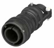
176 Go online for data sheets & assembly instructions. Visit www.radiall.com/vansystem and enter the part number. CVBS SHELL
ØQ L ØB A Ø F Shell size ØQ ±0.2 L max ØB ±0.2 A max ØF cable dimension Min Max 10SL 23.3 60 20 23 2.4 7.9 14S 29.5 67 24 26 5.8 11.2 16S 33 68 27 28.5 8 13.5 16 33 74 27 28.5 8 13.5 18 37 79.5 30 32 9.6 15.9 20 41 79.5 32 37.5 11.3 19 22 43 81.5 37 37.5 11.3 19 24 48 88.5 40 43.5 15.5 23.8 28 53 95.5 45 43.5 15.5 23.8 32 60 100 52 54 23.4 31.8 36 66.2 104.5 58 58 25.4 35 40 72.4 108 63.8 63.5 30 41.3 Dimension
Dimensions in mm IP67
“L” can be different from the value indicated according to backshells accessories, wires size and some special insert configurations.
CVBS - Bayonet Connector with protected mating ramps
RF Insulating material - Chloroprene rubber V Fluoride rubber S Silicone rubber RF Fire resistant rubber
ACF Connector Class
with waterproof O-ring and grommet (IP67) T Connector Modification** T With plastic caps 20-27 Insert Arrangement
-
S Contact Gender S Socket contacts P Pin contacts X Polarization Code**
Alternate Positions CR Contact Termination
- Solder contacts CR Crimp contacts
LC Less contacts
CD5 Contact Plating - Silver plating
CD5 Gold plating F7 Shell finish
F5 Electroless nickel (*)
F7 Black epoxy varnish (*)
F16
CCF - Black passivation (*) - conductive
F26 hard anodization (*)
Consult our sales office
177 Go online for data sheets & assembly instructions. Visit www.radiall.com/vansystem and enter the part number.
SHELL
CVBS
(*) RoHS compliance
Shell finish RF CVBS 06 ACF 20-27 S X CR CD5 F7 N T
Gasket A Ø F ØB H
MS3057...C
P/N Sample: RF CVBS 06ACFT 20-27SX CR CD5 F7 N Series Code Shell Type Connector Class
Shell Material Backshell Grommet cone (ACF Class only) Grommet (ACF Class only)
Cable-Clamp
(**) If required
06
Type 06 Plug Connector
CVBS Series Code CVBS Bayonet Connector with protected mating ramps Shell Material - Aluminum
Shell
ACF
AC with waterproof O-ring (IP67)
Size
Type
N
S
N Modification Code**
CVBS - Bayonet Connector with protected mating ramps
Plug Connector (06) with Backshell Class (ACB)
Connector provided with backshell, MS3057...C type Cable-Clamp and bushing MS 3420A (for jacketed cable)
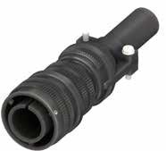
Dimension “L” can be different from the value indicated according to backshells accessories, wires size and some special insert configurations. Dimensions
178 Go online for data
Visit www.radiall.com/vansystem and enter the part number. CVBS SHELL
sheets & assembly instructions.
ØQ L ØB A F Ø Shell size ØQ ±0.2 L max ØB ±0.2 A max ØF max cable size 10SL 23.3 60 20 23 5.6 14S 29.5 67 24 26 7.9 16S 33 68 27 28.5 11.1 16 33 74 27 28.5 11.1 18 37 79.5 30 32 11.1 20 41 79.5 32 37.5 13.7 22 43 81.5 37 37.5 13.7 24 48 88.5 40 43.5 19 28 53 95.5 45 43.5 19 32 60 100 52 54 23.8 36 66.2 104.5 58 58 28.5 40 72.4 108 63.8 63.5 31.8
in mm
CVBS - Bayonet Connector with protected mating ramps
RF Insulating material - Chloroprene rubber V Fluoride rubber S Silicone rubber RF Fire resistant rubber
CVBS Series Code CVBS Bayonet Connector with protected mating ramps
Shell Material - Aluminum 06 Shell Type 06 Plug Connector
ACB Connector Class ACB with waterproof O-ring
T Connector Modification** T With plastic caps 20-27 Insert Arrangement Size - Type S Contact Gender S Socket contacts P Pin contacts X Polarization Code** Alternate Positions CR Contact Termination - Solder contacts
CR Crimp contacts
LC Less contacts
P/N
CD5 Contact Plating - Silver plating
F7 Shell finish
CD5 Gold plating
F5 Electroless nickel (*)
F7 Black epoxy varnish (*)
F16
CCF - Black passivation (*) - conductive
F26 hard anodization (*) N Modification Code** N Consult our sales office S
(*) RoHS compliance
(**) If required
179 Go online for data sheets &
Visit www.radiall.com/vansystem and enter the part number.
assembly instructions.
SHELL
CVBS
Sample: RF CVBS 06ACBT 20-27SX CR CD5 F7 N
RF
06 ACB 20-27 S X CR CD5 F7 N T
Backshell Gasket ØB A F Ø
MS3057...C bushing MS3420A
Series Code Shell Type Connector Class Shell finish
CVBS
Shell Material
Cable-Clamp
CVBS - Bayonet Connector with protected mating ramps
Plug Connector (06) with Backshell Class (LAC - LACF)
Connector provided with long backshell, MS3057...C type Cable-Clamp (for jacketed cable)
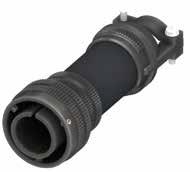
180 Go online for data sheets & assembly instructions. Visit www.radiall.com/vansystem and enter the part number. CVBS SHELL
ØQ L ØB A Ø F Shell size ØQ ±0.2 L max ØB ±0.2 A max ØF cable dimension Min Max 10SL 23.3 92 20 23 2.4 7.9 14S 29.5 92 24 26 5.8 11.2 16S 33 93 27 28.5 8 13.5 16 33 103.5 27 28.5 8 13.5 18 37 106 30 32 9.6 15.9 20 41 106 32 37.5 11.3 19 22 43 107 37 37.5 11.3 19 24 48 114.5 40 43.5 15.5 23.8 28 53 114.5 45 43.5 15.5 23.8 32 60 133.5 52 54 23.4 31.8 36 66.2 138 58 58 25.4 35 40 72.4 140.5 63.8 63.5 30 41.3 Dimension
can
different
value
accessories,
size
insert configurations. Dimensions in mm IP67
“L”
be
from the
indicated according to backshells
wires
and some special
CVBS - Bayonet Connector with protected mating ramps
Grommet cone (LACF Class only) Grommet (LACF Class only)
RF Insulating material - Chloroprene rubber V Fluoride rubber S Silicone rubber RF Fire resistant rubber
CVBS Series Code CVBS Bayonet Connector with protected mating ramps Shell Material - Aluminum
S Contact Gender
Socket contacts P Pin contacts X Polarization Code** Alternate Positions
CR Contact Termination
LACF Connector Class LAC with waterproof O-ring (IP67) LACF with waterproof O-ring and grommet (IP67)
T Connector Modification** T With plastic caps 20-27 Insert Arrangement
-
- Solder contacts CR Crimp contacts
LC Less contacts
CD5 Contact Plating - Silver plating
CD5 Gold plating F7 Shell finish
F5 Electroless nickel (*)
F7 Black epoxy varnish (*)
F16 CCF - Black passivation (*) - conductive
F26 hard anodization (*) N Modification Code**
Consult our sales office
(*) RoHS compliance
(**) If required
181 Go online for data sheets & assembly instructions. Visit www.radiall.com/vansystem and enter the part number.
SHELL
CVBS
P/N Sample: RF CVBS 06LACFT 20-27SX CR CD5 F7 N
Shell finish RF CVBS 06 LACF 20-27 S X CR CD5 F7 N T
Series Code Shell Type Connector Class
Shell Material Backshell
Gasket A Ø F ØB
MS3057...C
Cable-Clamp
06
Type 06 Plug
Shell
Connector
Size
Type
S
N
S
CVBS - Bayonet Connector with protected mating ramps
Plug Connector (06) with Backshell Class (AB)
Connector provided with backshell, MS3057...B type Cable-Clamp (for jacketed cable)
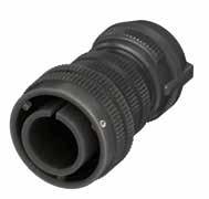
“L” can be different from the value indicated according to backshells accessories, wires size and some special insert configurations.
182 Go online for data sheets & assembly instructions. Visit www.radiall.com/vansystem and enter the part number. CVBS SHELL
ØQ L ØB A Ø F Shell size ØQ ±0.2 L ØB ±0.2 A max ØF cable dimension Min Max 10SL 23.3 48.4 20 23 2.4 7.9 14S 29.5 56.1 24 26 5.8 11.2 16S 33 57.3 27 28.5 8 13.5 16 33 63.3 27 28.5 8 13.5 18 37 68 30 32 9.6 15.9 20 41 69.2 32 37.5 11.3 19 22 43 71.2 37 37.5 11.3 19 24 48 76.3 40 43.5 15.5 23.8 28 53 83.3 45 43.5 15.5 23.8 32 60 85.1 52 54 23.4 31.8 36 66.2 88.2 58 58 25.4 35 40 72.4 91.5 63.8 63.5 30 41.3
Dimensions in mm
Dimension
CVBS - Bayonet Connector with protected mating ramps
Shell Material
Backshell Gasket
RF Insulating material - Chloroprene rubber V Fluoride rubber S Silicone rubber RF Fire resistant rubber
CVBS Series Code CVBS Bayonet Connector with protected mating ramps Shell Material - Aluminum 06 Shell Type 06 Plug Connector
AB Connector Class AB with waterproof O-ring
T Connector Modification** T With plastic caps
Cable-Clamp MS3057..B
CR Contact Termination
CD5 Contact Plating
20-27 Insert Arrangement Size - Type S Contact Gender S Socket contacts P Pin contacts X Polarization Code** Alternate Positions
P/N Sample:
- Solder contacts
CR Crimp contacts
LC Less contacts
- Silver plating
CD5 Gold plating
F5 Electroless nickel (*)
F7 Black epoxy varnish (*)
F16 CCF - Black passivation (*) - conductive
F26 hard anodization (*) N Modification Code** N
Consult our sales office S
(*) RoHS compliance
(**) If required
183 Go online for data sheets &
Visit www.radiall.com/vansystem and enter the part number.
SHELL
assembly instructions.
CVBS
RF CVBS 06ABT 20-27SX CR CD5 F7 N
AB 20-27
X CR CD5 F7 N T
Series Code Shell Type Connector Class Shell finish RF CVBS 06
S
A Ø F ØB
F7 Shell finish
CVBS - Bayonet Connector with protected mating ramps
Plug Connector (06) with Backshell Class (ASF)
Connector provided with backshell, MS3057...A type Cable-Clamp (for single wire)
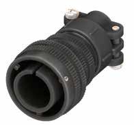
184 Go online for data sheets & assembly instructions. Visit www.radiall.com/vansystem and enter the part number. CVBS SHELL
L ØQ ØB A F Ø Shell size ØQ ±0.2 L max ØB ±0.2 A max ØF cable max dimension 10SL 23.3 46 20 22.5 8 14S 29.5 55 24 28 11 16S 33 56.5 27 30 14.2 16 33 62.5 27 30 14.2 18 37 67.5 30 31.7 15.8 20 41 68 32 37.5 19 22 43 70.5 37 37.5 19 24 48 70.5 40 43.5 23.8 28 53 77.5 45 43.5 23.8 32 60 77.5 52 51.7 31.7 36 66.2 77.5 58 58.5 35 40 72.4 93 63.8 68.5 41.2 Dimension “L” can be different from the value indicated according to backshells accessories, wires size and some special insert configurations. Dimensions in mm
CVBS - Bayonet Connector with protected mating ramps
RF Insulating material
- Chloroprene rubber V Fluoride rubber S Silicone rubber RF Fire resistant rubber CVBS
ASF Connector Class ASF with waterproof O-ring and grommet
T Connector Modification** T With plastic caps 20-27 Insert Arrangement Size - Type
S Contact Gender S Socket contacts P Pin contacts
X Polarization Code** Alternate Positions
CR Contact Termination
- Solder contacts
CR Crimp contacts
LC Less contacts
CD5 Contact Plating - Silver plating
CD5 Gold plating
F5 Electroless nickel (*)
F7 Black epoxy varnish (*)
F16
CCF - Black passivation (*) - conductive
F26 hard anodization (*) N Modification Code** N Consult our sales office S
185 Go online for data sheets & assembly instructions. Visit www.radiall.com/vansystem and enter the part number.
SHELL
CVBS
(*) RoHS compliance
06ASFT
CR CD5
Shell
RF CVBS 06 ASF 20-27 S X CR CD5 F7 N T Shell
P/N Sample: RF CVBS
20-27SX
F7 N Series Code Shell Type Connector Class
finish
Material (**) If required
Series Code CVBS Bayonet
Shell
-
06 Shell
06 Plug
Connector with protected mating ramps
Material
Aluminum
Type
Connector
F7 Shell finish
ØB A F Ø Cable-Clamp
Backshell
MS3057...A Grommet cone Grommet Gasket
CVBS - Bayonet Connector with protected mating ramps
Plug Connector (06) with Backshell Class (DA..M - RA..M DA..PG - RA..PG)
Connector with backshell provided with an internal Metric or PG thread suitable for Cable Glands or conduit adapters.
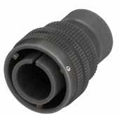
Dimensions “L1 and L2” can be different from the value indicated according to backshells accessories, wires size and some special insert configurations.
Dimensions in mm (...) The threads in parentheses are versions on request with non standard backshell length (the dimensions L2 and Z are different from this page indication). Please consult our sales office for the specific dimensions.
186 Go online for data sheets & assembly instructions. Visit www.radiall.com/vansystem and enter the part number. CVBS SHELL
ØB N Z ØQ L2 L1 Shell size ØQ ±0.2 ØB ±0.2 Z min L1 N Backshell Metric thread L2 M N Backshell PG Thread L2 PG 10SL 23.3 20 8 18,8 M12 - M16 32 (PG9) - PG13.5 26 14S 29.5 24 9 19,6 M12 - M16 - (M20) - (M25) 30 (PG9) - PG11 - PG13.5 - (PG16) 30 16S 33 27 9 19,6 (M16) - M20 40 PG13.5 - (PG16) 38 16 33 27 9 25,6 M20 45 - 40 18 37 30 9 24,9 M20 - M25 50 (PG11) - (PG13.5) - PG16 - PG21 50 20 41 32 9 25,3 M16 - M20 - M25 - (M32) 50 PG11-PG13.5-PG16-PG21-PG29 50 22 43 37 10 25,7 M16 - M20 - M25 - M32 50 PG13.5 - (PG16) - (PG29) 50 24 48 40 10 25,4 M20 - M25 - M32 - M40 50 PG16 - PG21 - PG29 50 28 53 45 10 25,8 (M25) - M32 - M40 63 PG21 - PG29 - PG36 60 32 60 52 10 28,3 (M25) - (M32) - M40 55 PG21 - (PG29) - PG36 60 36 66.2 58 13 28,1 M40 - M50 56 PG29 - (PG36) - (PG42) 65 40 72.4 63.8 13 28,6 M40 - (M50) - M63 65 PG29 - (PG36) - (PG42) - (PG48) 65
CVBS - Bayonet Connector with protected mating ramps
contacts
Crimp contacts LC Less contacts
F5 Electroless nickel (*)
F7 Black epoxy varnish (*)
F16
CCF - Black passivation (*) - conductive F26 hard anodization (*)
187 Go online for data sheets & assembly instructions. Visit www.radiall.com/vansystem and enter the part number.
SHELL
CVBS
P/N Sample: RF CVBS 06DAT 20-27SX M12 CR CD5 F7 N Series Code Shell Type Connector Class Shell finish RF CVBS 06 DA 20-27 S X CR CD5 F7 N T Shell Material B Ø Z H Z *1 *1 *2 Backshell Grommet cone (RA..M RA..PG Class only) Grommet (RA..M RA..PG Class only) Gasket M12 Backshell internal thread (*) RoHS compliance (**) If required *** Protection degree: IP 67 (only in the mating area with mated connectors) according to EN 60529 RF Insulating material - Chloroprene rubber V Fluoride rubber S Silicone rubber RF Fire resistant rubber CVBS Series Code CVBS Bayonet Connector with protected mating ramps Shell Material - Aluminum 06 Shell Type 06 Plug Connector DA Connector Class DA with waterproof O-ring (IP67***) RA with waterproof O-ring and grommet (IP67***) T Connector Modification** T With plastic caps 20-27
Arrangement Size - Type S
S Socket
P
X Polarization Code** Alternate
M12 Backshell internal thread M Provided
PG Provided
CD5 Contact
-
F7 Shell finish
Insert
Contact Gender
contacts
Pin contacts
Positions
with an internal Metric thread
with an internal PG thread CR Contact Termination - Solder
CR
Plating
Silver plating CD5 Gold plating
N
N Consult
S
Modification Code**
our sales office
CVBS - Bayonet Connector with protected mating ramps
Plug Connector (06) with Backshell Class (DA..MH - RA..MH DA..PH - RA..PH)
Connector with backshell provided with a Metric or PG thread metal Cable Glands.
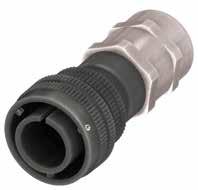
Dimension “L” can be different from the value indicated according to backshells accessories, wires size and some special insert configurations.
188 Go online for data sheets & assembly
Visit www.radiall.com/vansystem and enter the part number. CVBS SHELL
instructions.
L ØB N ØQ Shell size ØQ ±0.2 L max ØB ±0.2 Backshell Metric Thread ØN Clamping range 10SL 23.3 88 20 M12 3.5-7 14S 29.5 94 24 M16 4.5-10 16S 33 97.5 27 M20 7-13 16 33 105.5 27 M20 7-13 18 37 105.5 30 M20 7-13 20 41 106.5 32 M25 9-17 22 43 112.5 37 M32 11-21 24 48 112.5 40 M32 11-21 28 53 122.5 45 M32 11-21 32 60 126 52 M40 19-28 36 66.2 131 58 M40 19-28 40 72.4 139 63.8 M40 19-28
mm IP67
Dimensions in
CVBS - Bayonet Connector with protected mating ramps
Grommet (RA..MH RA..PH Class only)
Grommet cone (RA..MH RA..PH Class only)
RF Insulating material - Chloroprene rubber
Fluoride rubber S Silicone rubber
Fire resistant rubber
CR Contact Termination
Provided with a Metric thread Cable Glands
Provided with a PG thread Cable Glands**
- Solder contacts
CR Crimp contacts
LC Less contacts CD5 Contact Plating - Silver plating
CD5 Gold plating
F5 Electroless nickel (*)
F7 Black epoxy varnish (*)
F16
CCF - Black passivation (*) - conductive
F26 hard anodization (*)
189 Go online for data sheets & assembly instructions. Visit www.radiall.com/vansystem and enter the part number.
SHELL
CVBS
(*)
RF CVBS 06DAT 20-27SX MH12 CR CD5 F7 N Series Code Shell Type Connector Class Shell finish RF CVBS 06 DA 20-27 S X CR CD5 F7 N T
MH12
RoHS compliance P/N Sample:
Shell Material
Backshell internal thread
Backshell
Gasket
(**)
required ***
our
CVBS Series Code CVBS Bayonet
Shell Material - Aluminum 06 Shell Type 06 Plug Connector DA
Class DA with waterproof O-ring (IP67) RA with waterproof O-ring and grommet (IP67)
Modification** T With
caps 20-27
Size - Type
Gender S Socket contacts P Pin contacts
MH
Metal Cable Glands
If
Consult
sales office
V
RF
Connector with protected mating ramps
Connector
T Connector
plastic
Insert Arrangement
S Contact
X Polarization Code** Alternate Positions MH12 Backshell internal thread
PH
F7 Shell finish
N
Code** N Consult our
S
Modification
sales office
- Bayonet Connector with protected mating ramps Plug Connector (06) with Backshell Class (AR - R)
This class is suitable to connect single wires when strain relief is not necessary and small longitudinal overall dimensions are needed. As watertightness is guaranteed by the grommet only, it is necessary to make sure the wire diameter matches the grommet sealing range.
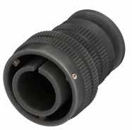
Dimensions in mm
Dimension “L” can be different from the value indicated according to backshells accessories, wires size and some special insert configurations.
190 Go online for data sheets & assembly instructions. Visit www.radiall.com/vansystem and enter the part number. CVBS SHELL
L ØB N ØQ Shell size ØQ ±0.2 ØB ±0.2 L max N max cable dimension 10SL 23.3 20 36 10 14S 29.5 24 42 13.5 16S 33 27 42 16.1 16 33 27 48 16.5 18 37 30 51 19 20 41 32 51 22.2 22 43 37 54 24.5 24 48 40 54 28 28 53 45 61 32.6 32 60 52 61 38 36 66.2 58 61 45 40 72.4 63.8 63 51.3
CVBS
CVBS - Bayonet Connector with protected mating ramps
The accessories for this class are not always available in stock for all sizes; we suggest you consult our Sales Office for availability
Contact Gender
Polarization
Socket contacts
contacts
Alternate Positions CR Contact Termination - Solder contacts CR Crimp contacts
LC Less contacts
CD5 Contact Plating - Silver plating
CD5 Gold plating
F5 Electroless nickel (*)
F7 Black epoxy varnish (*)
F16
CCF - Black passivation (*) - conductive
F26 hard anodization (*)
191 Go online for data sheets & assembly instructions. Visit www.radiall.com/vansystem and enter the part number.
SHELL
CVBS
(*)
RF CVBS 06RT 20-27SX CR CD5 F7 N Series Code Shell Type
Class Shell finish RF CVBS 06 R 20-27 S X CR CD5 F7 N T Shell Material ØB
RoHS compliance P/N Sample:
Connector
Gasket (R
RF
-
V Fluoride
S
RF
CVBS Series Code CVBS Bayonet Connector with protected mating ramps Shell Material - Aluminum 06 Shell Type 06 Plug Connector R Connector Class AR non watertight R with waterproof O-ring and grommet T
Modification** T With plastic caps 20-27 Insert Arrangement Size - Type S
X
Backshell Grommet cone (R Class only) Grommet (R Class only)
Class only) (**) If required
Insulating material
Chloroprene rubber
rubber
Silicone rubber
Fire resistant rubber
Connector
S
P Pin
Code**
F7
Shell finish
N
Code** N
S
Modification
Consult our sales office
CVBS - Bayonet Connector with protected mating ramps
Plug Connector (06) with Backshell Class (AG - G)
These classes of connectors are all suitable for heat shrink tubing applications.
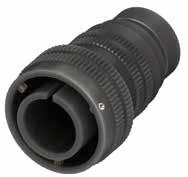
Dimensions in mm
Dimension “L” can be different from the value indicated according to backshells accessories, wires size and some special insert configurations.
192 Go online for data sheets & assembly instructions. Visit www.radiall.com/vansystem and enter the part number. CVBS SHELL
L ØD3 L1 L2 ØD2 ØB ØD1 ØD4 ØQ Shell size ØQ ±0.2 ØB ±0.2 ØD1 ±0.2 ØD2 ±0.2 ØD3 ±0.2 ØD4 ±0.2 L L1 ±0.2 L2 ±0.2 10SL 23.3 20 17 15.5 13.3 7.9 49 11.7 3.5 14S 29.5 24 20.1 19.1 17 13.5 49 11.7 3.5 16S 33 27 23.5 23.9 21.9 13.7 49 11.7 3.5 16 33 27 23.5 23.9 21.9 16.1 60 11.5 3.5 18 37 30 26.5 23.9 21.9 19 64 11.5 3.5 20 41 32 30.2 29.6 26.2 22.2 64 12.4 3.5 22 43 37 33.6 29.6 26.2 22 64 12.7 3.5 24 48 40 36.1 37.8 34.5 28 64 12.7 3.5 28 53 45 41.4 37.8 34.5 29 64 12.7 3.5 32 60 52 50 47.8 43.4 35.2 70 15.2 3.5 36 66.2 58 56 47.7 43.4 40 75 15.2 3.5 40 72.4 63.8 62.4 57.6 52.4 48 78 15.2 3.5
CVBS - Bayonet Connector with protected mating ramps
Series Code Shell Type Connector Class
Backshell Grommet cone (G Class only) Grommet (G Class only) Gasket
The accessories for this class are not always available in stock for all sizes; we suggest you consult our Sales Office for availability
RF Insulating material - Chloroprene rubber V Fluoride rubber S Silicone rubber RF Fire resistant rubber
CVBS Series Code CVBS Bayonet Connector with protected mating ramps
Shell Material - Aluminum 06 Shell Type 06 Plug Connector
AG Connector Class AG with waterproof O-ring (IP67***) G with waterproof O-ring and grommet (IP67***)
T Connector Modification** T With plastic caps
20-27 Insert Arrangement Size - Type
S Contact Gender S Socket contacts
P Pin contacts
X Polarization Code** Alternate Positions
CR Contact Termination
- Solder contacts
CR Crimp contacts
LC Less contacts
CD5 Contact Plating - Silver plating
F7 Shell finish
CD5 Gold plating
F5 Electroless nickel (*)
F7 Black epoxy varnish (*)
F16
CCF - Black passivation (*) - conductive
F26 hard anodization (*)
N Modification Code** N
Consult our sales office S
*** Protection degree: IP 67 (only in the mating area with mated connectors) according to EN 60529
P/N Sample: RF CVBS 06AGT 20-27SX CR CD5 F7 N
(*) RoHS compliance (**) If required
193 Go online for data sheets
Visit www.radiall.com/vansystem and enter the part number.
& assembly instructions.
SHELL
CVBS
finish RF CVBS 06 AG 20-27 S X CR CD5 F7 N T Shell
L1 L2 ØD2 ØB ØD1 ØD4
Shell
Material ØD3
CVBS - Bayonet Connector with protected mating ramps
Plug Connector (06) with Backshell Class (DA..FS - RA..FS)
Connector with special adapter for rubber conduits.
Conduit’s size must be specified adding the diameter dimensions in the P/N (i.e.: CVBS 06DA…FS5040…).
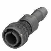
Please consult our Sales Office for further details about this dimension and according to conduit size.
194 Go online for data sheets & assembly instructions. Visit www.radiall.com/vansystem and enter the part number. CVBS SHELL
ØQ L ØB Ø 1 A Ø 2 A Shell size ØQ ±0.2 L max ØB max 18 37 103 30 20 41 103 32 22 43 103 37 24 48 105 40 28 53 111 45 32 60 117 52 36 66.2 122 58 40 72.4 122 63.8 Dimension “L” can be different from the value indicated according to backshells accessories, wires size and some special insert configurations. Dimensions in mm
* * Rubber Conduit not included Backshell Conduit Size ØA1* ØA2* FS1712 17 12 FS1813 18 13 FS2015 20 15 FS2318 23 18 FS2520 25 20 FS2618 26 18 FS2620 26 20 FS2722 27 22 FS2820 28 20 FS3328 33 28 Backshell Conduit Size ØA1* ØA2* FS3530 35 30 FS4030 40 30 FS4035 40 35 FS4236 42 36 FS4540 45 40 FS4843 48 43 FS5040 50 40 FS5045 50 45 FS5550 55 50 FS5945 59 45
CVBS - Bayonet Connector with protected mating ramps
The accessories for this class are not always available in stock for all sizes; we suggest you consult our Sales Office for availability
with waterproof O-ring and grommet (IP67***) #
Connector Modification**
Contact Gender
CR Contact Termination
Provided with a special adapter for rubber conduits
- Solder contacts
Crimp contacts
Less contacts
CD5 Contact Plating - Silver plating
CD5 Gold plating
F5 Electroless nickel (*)
F7 Black epoxy varnish (*)
F16
CCF - Black passivation (*) - conductive
F26 hard anodization (*)
Consult our sales office
195 Go online for data sheets & assembly instructions. Visit www.radiall.com/vansystem and enter the part number. CVBS SHELL
Sample: RF CVBS 06DAT 20-27SX FS5040 CR CD5 F7 N Series Code Shell Type Connector Class Shell finish RF CVBS 06 DA 20-27 S X CR CD5 F7 N T Shell Material FS.. (*) RoHS compliance (**) If required *** Protection degree: IP 67 (only in the mating area with mated connectors) according to EN 60529 Backshell Grommet cone
Grommet
Gasket Adapter Gasket
(#) In some sizes the grommet cone is not needed Backshell
size xxxx RF
-
V Fluoride
S Silicone rubber RF Fire
CVBS Series Code CVBS Bayonet Connector with protected mating ramps Shell Material - Aluminum 06 Shell Type 06 Plug Connector
DA
RA
Size
P/N
(RA..FS Class only)
(RA..FS Class only)
Conduits
Insulating material
Chloroprene rubber
rubber
resistant rubber
DA Connector Class
with waterproof O-ring (IP67***)
T
T With plastic caps 20-27 Insert Arrangement
- Type
FS
xxxx Conduit Size xxxx ØA1ØA2
S
S Socket contacts P Pin contacts X Polarization Code** Alternate Positions FS.. Backshell Conduits size
CR
LC
F7
finish
Shell
N
N Modification Code**
S
CVBS - Bayonet Connector with protected mating ramps
Plug Connector (06) with Backshell Class (DA..MTG - RA..MTG)
Connector with a special adapter for clamping and retaining rubber conduits, with nut. Conduit’s size must be specified adding the diameter dimensions in the P/N (i.e.: CVBS 06DA…MTG2025…).
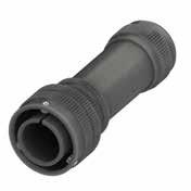
196 Go online for data sheets & assembly instructions. Visit www.radiall.com/vansystem and enter the part number. CVBS SHELL
ØQ L Ø 1 A Ø 2 A ØB Shell size ØQ ±0.2 L max ØB max 18 37 101 30 20 41 101 32 22 43 101 37 24 48 107 40 28 53 110 45 32 60 114 52 36 66.2 120 58 40 72.4 121 63.8 Dimension “L” can be different from the value indicated according to backshells accessories, wires size and some special insert configurations. Dimensions in mm * * Rubber Conduit not included * Dimensions ØA1 and ØA2 are determined by conduit size. Backshell Conduit Size ØA1* ØA2* Shell size MTG1712 17 12 18 MTG2015 20 15 18-24 MTG2318 23 18 24-32 MTG2520 25 20 28 MTG2924 29 24 28 MTG3328 33 28 36-32 MTG3530 35 30 36 MTG3628 36 28 36 MTG3833 38 33 40 MTG4035 40 35 40 MTG4237 42 37 40 MTG4238 42 38 40 MTG4840 48 40 40
CVBS - Bayonet Connector with protected mating ramps
Backshell Conduits size or internal thread
(RA..MTG Class only)
cone (RA..MTG Class only)
Backshell
The accessories for this class are not always available in stock for all sizes; we suggest you consult our Sales Office for availability
resistant rubber
with waterproof O-ring and grommet (IP67***) # T Connector Modification**
With plastic caps
Insert Arrangement
Backshell Conduits size or internal thread
Provided with a special adapter for rubber conduits, with nut.
CR Contact Termination - Solder contacts
Crimp contacts LC Less contacts
CD5 Contact Plating - Silver plating
CD5 Gold plating F7 Shell finish
F5 Electroless nickel (*)
F7 Black epoxy varnish (*)
F16
CCF - Black passivation (*) - conductive
F26 hard anodization (*)
197 Go online for data sheets & assembly instructions. Visit www.radiall.com/vansystem and enter the part number. CVBS SHELL
Sample: RF CVBS 06DAT 20-27SX MTG2025 CR CD5 F7 N (*) RoHS compliance (**) If required *** Protection degree: IP 67 (only in the mating area with mated connectors) according to EN 60529
Retention System
P/N
Grommet
Grommet
Gasket
(#)
Gasket Clamping Nut Series Code Shell Type Connector Class Shell finish RF CVBS 06 DA 20-27 S X CR CD5 F7 N T Shell Material MTG
2520 Conduit
-
V Fluoride
S
RF Fire
CVBS Series Code CVBS Bayonet Connector with protected mating ramps Shell Material - Aluminum 06 Shell Type 06 Plug Connector
DA
RA
20-27
Size
S Socket
P Pin contacts X
Code** Alternate Positions MTG
MTG
In some sizes the grommet cone is not needed
Size RF Insulating material
Chloroprene rubber
rubber
Silicone rubber
DA Connector Class
with waterproof O-ring (IP67***)
T
- Type S Contact Gender
contacts
Polarization
2520 Conduit Size xxxx ØA1ØA2
CR
N
Code** N
our
S
Modification
Consult
sales office
CVBS - Bayonet Connector with protected mating ramps
Plug Connector (06) with Backshell Class (AG2 - G2)
These classes of connectors are all suitable for heat shrink tubing applications. Two piece backshell includes nut for shell tightening. Internal serration prevents backshell rotation and allows easy assembling after contacts are inserted.
Dimensions in mm
Dimension “L” can be different from the value indicated according to backshells accessories, wires size and some special insert configurations.
198 Go online for data sheets & assembly instructions. Visit www.radiall.com/vansystem and enter the part number. CVBS SHELL
L ØD1 ØD3 ØB L1 L2 ØD2 ØD4 ØQ Shell size ØQ ØB ±0.2 ØD1 ±0.2 ØD2 ±0.2 ØD3 ±0.2 ØD4 ±0.2 L L1 ±0.2 L2 ±0.2 10SL 23.3 22.5 17 15.5 13.3 8.6 51 11.7 3.5 14S 29.5 26 20.1 19.1 17 10.8 52 11.7 3.5 16S 33 29 23.5 23.9 21.9 14 53.5 11.7 3.5 16 33 29 23.5 23.9 21.9 14 62 11.5 3.5 18 37 33.4 26.5 23.9 21.9 14.8 61.5 11.5 3.5 20 41 37 30.2 29.6 26.2 19.3 62.5 12.4 3.5 22 43 41 33.6 29.6 26.2 22.5 62.5 12.7 3.5 24 48 45.9 36.1 37.8 34.5 28 63 12.7 3.5 28 53 51 41.4 37.8 34.5 28 65 12.7 3.5 32 60 58 50 47.8 43.4 34.8 67 15.2 3.5 36 66.2 60.5 56 47.7 43.4 38.7 67 15.2 3.5 40 72.4 69 62.4 57.6 52.4 48.2 68.5 15.2 3.5
CVBS - Bayonet Connector with protected mating ramps
The accessories for this class are not always available in stock for all sizes; we suggest you consult our Sales Office for availability
Insulating
With waterproof O-ring and grommet (IP67***)# T Connector Modification** T With plastic caps 20-27 Insert Arrangement Size - Type S Contact Gender S Socket contacts P Pin contacts
G2 Connector Class
With waterproof O-ring (IP67***)
Polarization Code** Alternate Positions CR Contact Termination - Solder contacts CR Crimp contacts
LC Less contacts
CD5 Contact Plating - Silver plating
Protection degree: IP 67 (only in the mating area with mated connectors) according to EN 60529
CD5 Gold plating
F5 Electroless nickel (*)
F7 Black epoxy varnish (*)
F16
CCF - Black passivation (*) - conductive
F26 hard anodization (*)
office S
RoHS compliance (**) If required
199 Go online for data sheets & assembly instructions. Visit www.radiall.com/vansystem and enter the part number.
SHELL
Shell finish G2
CVBS
Series Code Shell Type Connector Class
Two piece backshell Grommet cone (G2 Class only) Grommet (G2 Class only) Gasket P/N Sample: RF CVBS 06G2T 20-27SX CR CD5 F7 N RF CVBS 06 G2 20-27 S X CR CD5 F7 N T Shell Material
***
(*)
(#) In some sizes the grommet cone is not needed
CVBS Series Code CVBS Bayonet
mating
Shell Material - Aluminum 06 Shell Type 06 Plug Connector
RF
material - Chloroprene rubber V Fluoride rubber S Silicone rubber RF Fire resistant rubber
Connector with protected
ramps
AG2
G2
X
F7 Shell finish
N Modification Code** N Consult our sales
CVBS - Bayonet Connector with protected mating ramps
Plug Connector (06) with Backshell Class (AWN - WN)
Connectors is provided with gasket and iris spring connected to one another by an internal ring. When screwing the rear oupling nut, the gasket and the spring tighten around the cable or the hose, so to guarantee an excellent mechanical strain relief and watertightness. Clamping range on the dimension table has to be chosen according to the cable size and its shielding and specified in the connector P/N.
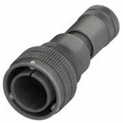
Dimension “L” can be different from the value indicated according to backshells accessories, wires size and some special insert configurations.
*** On request
* Must be specified in the connector
** Clamping range to be verified with cable section. Please consult our Sales Office.
200 Go online for data sheets & assembly instructions. Visit www.radiall.com/vansystem and enter the part number. CVBS SHELL
L ØQ ØB Shell size ØQ ØB L 10SL 23.3 20 *** 14S 29.5 24 *** 16S 33 27 *** 16 33 27 *** 18 37 30 *** 20 41 32 100 22 43 37 *** 24 48 40 *** 28 53 45 *** 32 60 52 *** 36 66.2 58 *** 40 72.4 63.8 ***
Dimensions in mm
Size * Clamping Range ** max min 01 6 3 02 9.5 5 03 13 8.5 04 16.5 12 05 20 15.5 06 23.5 19 07 27 22.5 08 30.5 26 09 34 29.5 10 37.5 33 11 41 36.5 12 44.5 40 13 48 43.5 14 51.5 47
CVBS - Bayonet Connector with protected mating ramps
201 Go online for data sheets & assembly instructions. Visit www.radiall.com/vansystem and enter the part number. CVBS SHELL Series Code Shell Type Connector Class Shell finish
The accessories for this class are not always available in stock for all sizes; we suggest you consult our Sales Office for availability Backshell Grommet cone (WN Class only) Grommet (WN Class only) Gasket P/N Sample: RF CVBS 06WNT01 20-27SX CR CD5 F7 N RF CVBS 06 WN 20-27 S X CR CD5 F7 N T Shell Material (*) RoHS compliance (**) If required *** Protection degree: IP 67 (only in the mating area with mated connectors) according to EN 60529 (#) In some sizes the grommet cone is not needed Gasket Internal Ring 01 Clamping Range Type Iris Spring Rear Nut RF Insulating material - Chloroprene rubber V Fluoride rubber S Silicone rubber RF Fire resistant rubber CVBS Series Code CVBS Bayonet Connector with protected mating ramps Shell Material - Aluminum 06 Shell Type 06 Plug Connector WN Connector Class AWN with waterproof O-ring (IP67***) WN With waterproof O-ring and grommet (IP67***)# T Connector Modification** T With plastic caps 01 Clamping Size xx Clamping Range 20-27 Insert Arrangement Size - Type S Contact Gender S Socket contacts P Pin contacts X Polarization Code** Alternate Positions CR Contact Termination - Solder contacts CR Crimp
LC Less
CD5 Contact
- Silver
CD5
F7 Shell finish F5 Electroless
F7
F16 CCF
(*)
F26 hard
N Modification Code** N Consult our sales office S
contacts
contacts
Plating
plating
Gold plating
nickel (*)
Black epoxy varnish (*)
- Black passivation
- conductive
anodization (*)
CVBS - Bayonet Connector with protected mating ramps
Plug Connector (96) with Backshell Class (AC - ACF)
Connector provided with grounding finger to guarantee shielding; with backshell, MS3057...C type Cable-Clamp (for jacketed cable)
Grounding finger
202 Go online for data sheets
Visit www.radiall.com/vansystem and enter the part number. CVBS SHELL
& assembly instructions.
ØQ L ØB A Ø F Shell size ØQ ±0.2 L max ØB ±0.2 A max ØF cable dimension Min Max 10SL 23.3 60 20 23 2.4 7.9 14S 29.5 67 24 26 5.8 11.2 16S 33 68 27 28.5 8 13.5 16 33 74 27 28.5 8 13.5 18 37 79.5 30 32 9.6 15.9 20 41 79.5 32 37.5 11.3 19 22 43 81.5 37 37.5 11.3 19 24 48 88.5 40 43.5 15.5 23.8 28 53 95.5 45 43.5 15.5 23.8 32 60 100 52 54 23.4 31.8 36 66.2 104.5 58 58 25.4 35 40 72.4 108 63.8 63.5 30 41.3 Dimension
value
Dimensions in mm IP67
“L” can be different from the
indicated according to backshells accessories, wires size and some special insert configurations.
CVBS - Bayonet Connector with protected mating ramps
RF Insulating material - Chloroprene rubber V Fluoride rubber S Silicone rubber
RF Fire resistant rubber
CVBS Series Code CVBS Bayonet Connector with protected mating ramps
Shell Material - Aluminum
ACF Connector Class AC with waterproof O-ring (IP67) ACF with waterproof O-ring and grommet (IP67)
T Connector Modification** T With plastic caps
P/N
20-27 Insert Arrangement
Size - Type
S Contact Gender S Socket contacts P Pin contacts X Polarization Code** Alternate Positions
CR Contact Termination - Solder contacts
CR Crimp contacts
LC Less contacts
CD5 Contact Plating - Silver plating
CD5 Gold plating
F16 Shell finish F16
CCF - Black passivation (*) - conductive N Modification Code** N
Consult our sales office S
(*) RoHS compliance
203 Go online for data sheets &
Visit www.radiall.com/vansystem and enter the part number.
SHELL
assembly instructions.
CVBS
Sample: RF CVBS 96ACFT 20-27SX CR CD5 F16 N
Shell finish RF CVBS 96 ACF 20-27 S X CR CD5 F16 N T
Gasket A Ø F ØB H
MS3057...C
Series Code Shell Type Connector Class
Shell Material Backshell Grommet cone (ACF Class only) Grommet (ACF Class only)
Cable-Clamp
(**) If required
96 Shell Type 96 Plug Connector with grounding finger
CVBS - Bayonet Connector with protected mating ramps
Plug Connector (96) with Backshell Class (DA..M - RA..M DA..PG - RA..PG)
Connector provided with grounding finger to guarantee shielding; with backshell provided with an internal Metric or PG thread suitable for Cable Glands or conduit adapters.
Dimensions in
Dimensions “L1 and L2” can be different from the value indicated according to backshells accessories, wires size and some special insert configurations.
(...) The threads in parentheses are versions on request with non standard backshell length (the dimensions L2 and Z are different from this page indication). Please consult our sales office for the specific dimensions.
204 Go online for data sheets & assembly instructions. Visit www.radiall.com/vansystem and enter the part number. CVBS SHELL
ØB N Z ØQ L2 L1 Grounding finger Shell size ØQ ±0.2 ØB ±0.2 Z min L1 N Backshell Metric thread L2 M N Backshell PG Thread L2 PG 10SL 23.3 20 8 18,8 M12 - M16 32 (PG9) - PG13.5 26 14S 29.5 24 9 19,6 M12 - M16 - (M20) - (M25) 30 (PG9) - PG11 - PG13.5 - (PG16) 30 16S 33 27 9 19,6 (M16) - M20 40 PG13.5 - (PG16) 38 16 33 27 9 25,6 M20 45 - 40 18 37 30 9 24,9 M20 - M25 50 (PG11) - (PG13.5) - PG16 - PG21 50 20 41 32 9 25,3 M16 - M20 - M25 - (M32) 50 PG11-PG13.5-PG16-PG21-PG29 50 22 43 37 10 25,7 M16 - M20 - M25 - M32 50 PG13.5 - (PG16) - (PG29) 50 24 48 40 10 25,4 M20 - M25 - M32 - M40 50 PG16 - PG21 - PG29 50 28 53 45 10 25,8 (M25) - M32 - M40 63 PG21 - PG29 - PG36 60 32 60 52 10 28,3 (M25) - (M32) - M40 55 PG21 - (PG29) - PG36 60 36 66.2 58 13 28,1 M40 - M50 56 PG29 - (PG36) - (PG42) 65 40 72.4 63.8 13 28,6 M40 - (M50) - M63 65 PG29 - (PG36) - (PG42) - (PG48) 65
mm
CVBS - Bayonet Connector with protected mating ramps
Contact Gender
Socket contacts
Pin contacts
Polarization Code** Alternate Positions
with an internal Metric thread
Provided with an internal PG thread
Solder contacts
Contact Termination
Crimp contacts
Less contacts
With plastic caps
Insert Arrangement
205 Go online for data sheets & assembly instructions. Visit www.radiall.com/vansystem and enter the part number.
SHELL
CVBS
RF CVBS 96DAT 20-27SX M12 CR CD5 F16 N Series
Type
Class Shell finish RF CVBS 96 DA 20-27 S X CR CD5 F16 N T B Ø Z H Z *1 *1 *2
RA..PG
RA..PG
Gasket M12
(*)
***
Shell
-
V
S
RF
CVBS Series Code CVBS Bayonet Connector with protected mating
Shell Material - Aluminum 96 Shell Type 96 Plug Connector with grounding finger DA
DA with
RA
T
Size
S
S
P
X
M12
M
PG
CR
CR
CD5
-
CD5
F16 Shell finish F16 CCF
(*)
N
N
S
P/N Sample:
Code Shell
Connector
Backshell Grommet cone (RA..M
Class only) Grommet (RA..M
Class only)
Backshell internal thread
RoHS compliance (**) If required
Protection degree: IP 67 (only in the mating area with mated connectors) according to EN 60529
Material RF Insulating material
Chloroprene rubber
Fluoride rubber
Silicone rubber
Fire resistant rubber
ramps
Connector Class
waterproof O-ring (IP67***)
with waterproof O-ring and grommet (IP67***) T Connector Modification**
20-27
- Type
Backshell internal thread
Provided
-
LC
Contact Plating
Silver plating
Gold plating
- Black passivation
- conductive
Modification Code**
Consult our sales office
CVBS - Bayonet Connector with protected mating ramps
Plug Connector (96) with Backshell Class (DA..FS - RA..FS)
Connector provided with grounding finger to guarantee shielding; with special adapter for rubber conduits. Conduit’s size must be specified adding the diameter dimensions in the P/N (i.e.: CVBS 06DA…FS5040…).
Please consult our Sales Office for further details about this dimension and according to conduit size.
206 Go online for data sheets & assembly instructions. Visit www.radiall.com/vansystem and enter the part number. CVBS SHELL
ØQ L ØB Ø 1 A Ø 2 A Shell size ØQ ±0.2 L max ØB max 18 37 103 30 20 41 103 32 22 43 103 37 24 48 105 40 28 53 111 45 32 60 117 52 36 66.2 122 58 40 72.4 122 63.8 Dimension “L” can be different from the value indicated according to backshells accessories, wires size and some special insert configurations. Dimensions in mm
Grounding finger * * Rubber Conduit not included Backshell Conduit Size ØA1* ØA2* FS1712 17 12 FS1813 18 13 FS2015 20 15 FS2318 23 18 FS2520 25 20 FS2618 26 18 FS2620 26 20 FS2722 27 22
28 20 FS3328 33 28 Backshell Conduit Size ØA1* ØA2* FS3530 35 30 FS4030 40 30 FS4035 40 35 FS4236 42 36 FS4540 45 40 FS4843 48 43 FS5040 50 40 FS5045 50 45 FS5550 55 50 FS5945 59 45
FS2820
CVBS - Bayonet Connector with protected mating ramps
(RA..FS Class only)
The accessories for this class are not always available in stock for all sizes; we suggest you consult our Sales Office for availability
Connector Class
with waterproof O-ring (IP67***)
with waterproof O-ring and grommet (IP67***) # T Connector Modification** T With plastic caps 20-27 Insert Arrangement Size - Type S Contact Gender
contacts
Contact Termination
Provided with a special adapter for rubber conduits
- Solder contacts CR Crimp contacts LC Less contacts
CD5 Contact Plating - Silver plating
CD5 Gold plating
F5 Electroless nickel (*)
F7 Black epoxy varnish (*)
F16
CCF - Black passivation (*) - conductive
F26 hard anodization (*)
Consult our sales office
207 Go online for data sheets & assembly instructions. Visit www.radiall.com/vansystem and enter the part number. CVBS SHELL
RF CVBS 96DAT 20-27SX FS5040 CR CD5 F7 N
Type
Class Shell finish RF CVBS 96 DA 20-27 S X CR CD5 F7 N T Shell Material FS.. (*) RoHS compliance
required *** Protection degree: IP 67
in
mating area
mated connectors) according to EN 60529
Grommet
Gasket Adapter
P/N Sample:
Series Code Shell
Connector
(**) If
(only
the
with
Backshell Grommet cone (RA..FS Class only)
Gasket
(#)
not needed Backshell
xxxx
V
S
RF
CVBS
-
96 Shell Type 96 Plug Connector
grounding
DA
RA
X
FS
In some sizes the grommet cone is
Conduits size
RF Insulating material - Chloroprene rubber
Fluoride rubber
Silicone rubber
Fire resistant rubber CVBS Series Code
Bayonet Connector with protected mating ramps Shell Material
Aluminum
with
finger DA
S Socket
P Pin contacts
Polarization Code** Alternate Positions FS.. Backshell Conduits size
xxxx
Conduit Size xxxx ØA1ØA2 CR
F7
Shell finish
N
N Modification Code**
S
CVBS - Bayonet Connector with protected mating ramps
Plug Connector (96) with Backshell Class (DA..MTG - RA..MTG)
Connector provided with grounding finger to guarantee shielding; with a special adapter for clamping and retaining rubber conduits, with nut.
Conduit’s size must be specified adding the diameter dimensions in the P/N (i.e.: CVBS 96DA…MTG2520…).
Grounding
208 Go online for data sheets & assembly instructions. Visit www.radiall.com/vansystem and enter the part number. CVBS SHELL
ØQ L Ø 1 A Ø 2 A ØB * * Rubber Conduit not included
Shell size ØQ ±0.2 L max ØB max 18 37 101 30 20 41 101 32 22 43 101 37 24 48 107 40 28 53 110 45 32 60 114 52 36 66.2 120 58 40 72.4 121 63.8 Dimension “L” can be different from the value indicated according to backshells accessories, wires size and some special insert configurations. Dimensions in mm * Dimensions ØA1 and ØA2 are determined by conduit size. Backshell Conduit Size ØA1* ØA2* Shell size MTG1712 17 12 18 MTG2015 20 15 18-24 MTG2318 23 18 24-32 MTG2520 25 20 28 MTG2924 29 24 28 MTG3328 33 28 36-32 MTG3530 35 30 36 MTG3628 36 28 36 MTG3833 38 33 40 MTG4035 40 35 40 MTG4237 42 37 40 MTG4238 42 38 40 MTG4840 48 40 40
finger
CVBS - Bayonet Connector with protected mating ramps
Backshell Conduits size or internal thread
Backshell Grommet cone (RA..MTG Class only) Grommet (RA..MTG Class only) Gasket
The accessories for this class are not always available in stock for all sizes; we suggest you consult our Sales Office for availability
RF Insulating material - Chloroprene rubber
rubber
rubber
resistant rubber CVBS
DA Connector Class
with waterproof O-ring (IP67***)
with waterproof O-ring and grommet (IP67***) #
T Connector Modification** T With plastic caps 20-27 Insert Arrangement Size - Type
S Contact Gender
contacts P Pin contacts
Backshell Conduits size or internal thread
Provided with a special adapter for rubber conduits, with nut.
CR Contact Termination - Solder contacts
Crimp contacts LC Less contacts
CD5 Contact Plating - Silver plating
CD5 Gold plating F7 Shell finish
F5 Electroless nickel (*)
F7 Black epoxy varnish (*)
F16
CCF - Black passivation (*) - conductive
F26 hard anodization (*)
209 Go online for data sheets & assembly instructions. Visit www.radiall.com/vansystem and enter the part number. CVBS SHELL
RF CVBS 96DAT 20-27SX MTG2520 CR CD5 F7 N
Type
Class Shell finish RF CVBS 96 DA 20-27 S X CR CD5 F7 N T
MTG
P/N Sample:
Series Code Shell
Connector
Shell Material
(*) RoHS compliance (**) If required *** Protection degree: IP 67 (only
mating area
mated connectors) according to EN 60529
Retention
in the
with
System
(#) In some sizes the grommet cone is not needed Gasket Clamping Nut 2520
Conduit Size
CVBS
96 Shell Type 96 Plug
V Fluoride
S Silicone
RF Fire
Series Code
Bayonet Connector with protected mating ramps Shell Material - Aluminum
Connector with grounding finger
DA
RA
X
MTG
S Socket
Polarization Code** Alternate Positions
MTG
2520 Conduit Size xxxx ØA1ØA2
CR
N
N
S
Modification Code**
Consult our sales office
CVBS - Bayonet Connector with protected mating ramps
Plug Connector (96) with Backshell Class (AG2 - G2)
Connector provided with grounding finger to guarantee shielding; These classes of connectors are all suitable for heat shrink tubing applications. Two piece backshell includes nut for shell tightening. Internal serration prevents backshell rotation and allows easy assembling after contacts are inserted.
Grounding finger
Dimensions in mm
Dimension “L” can be different from the value indicated according to backshells accessories, wires size and some special insert configurations.
210 Go online for data sheets & assembly instructions. Visit www.radiall.com/vansystem and enter the part number. CVBS SHELL
L ØD1 ØD3 ØB L1 L2 ØD2 ØD4 ØQ Shell size ØQ ØB ±0.2 ØD1 ±0.2 ØD2 ±0.2 ØD3 ±0.2 ØD4 ±0.2 L L1 ±0.2 L2 ±0.2 10SL 23.3 22.5 17 15.5 13.3 8.6 51 11.7 3.5 14S 29.5 26 20.1 19.1 17 10.8 52 11.7 3.5 16S 33 29 23.5 23.9 21.9 14 53.5 11.7 3.5 16 33 29 23.5 23.9 21.9 14 62 11.5 3.5 18 37 33.4 26.5 23.9 21.9 14.8 61.5 11.5 3.5 20 41 37 30.2 29.6 26.2 19.3 62.5 12.4 3.5 22 43 41 33.6 29.6 26.2 22.5 62.5 12.7 3.5 24 48 45.9 36.1 37.8 34.5 28 63 12.7 3.5 28 53 51 41.4 37.8 34.5 28 65 12.7 3.5 32 60 58 50 47.8 43.4 34.8 67 15.2 3.5 36 66.2 60.5 56 47.7 43.4 38.7 67 15.2 3.5 40 72.4 69 62.4 57.6 52.4 48.2 68.5 15.2 3.5
CVBS - Bayonet Connector with protected mating ramps
Material
The accessories for this class are not always available in stock for all sizes; we suggest you consult our Sales Office for availability
RF Insulating material - Chloroprene rubber V Fluoride rubber S Silicone rubber RF Fire resistant rubber CVBS
20-27 Insert Arrangement Size - Type S Contact Gender S Socket contacts P Pin contacts X Polarization Code** Alternate Positions CR Contact Termination - Solder contacts CR Crimp contacts
Plug Connector with grounding finger
With waterproof O-ring (IP67***)
G2 Connector Class
With waterproof O-ring and grommet (IP67***)# T Connector Modification** T With plastic caps
LC Less contacts
CD5 Contact Plating - Silver plating
CD5 Gold plating
F5 Electroless nickel (*)
F7 Black epoxy varnish (*)
F16
CCF - Black passivation (*) - conductive
F26 hard anodization (*) N Modification Code**
Consult our sales office S
RoHS compliance (**) If required
Protection degree: IP 67 (only in the mating area with mated connectors) according to EN 60529 (#) In some sizes the grommet cone is not needed
211 Go online for data sheets &
Visit www.radiall.com/vansystem and enter the part number.
SHELL
G2
assembly instructions.
CVBS
Series Code Shell Type Connector Class Shell finish
piece
Grommet cone (G2 Class only) Grommet (G2 Class only) Gasket
RF CVBS 96G2T 20-27SX CR CD5 F7 N RF CVBS 96 G2 20-27 S X CR CD5 F7 N T Shell
Two
backshell
P/N Sample:
(*)
***
CVBS
-
96
Series Code
Bayonet Connector with protected mating ramps Shell Material
Aluminum 96 Shell Type
AG2
G2
F7
Shell finish
N
CVBS - Bayonet Connector with protected mating ramps
Plug Connector (96) with Backshell Class (ASB1 - SB1)
Connector provided with grounding finger to guarantee shielding; Backshell for multicore jacketed shielded cables, provided with MS 3057…C type Cable-Clamp. (for jacketed cable) Also available versions for over/under dimensioned cables.
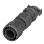
212 Go online for data sheets & assembly instructions. Visit www.radiall.com/vansystem and enter the part number. CVBS SHELL
L ØB A Ø F ØQ Shell size ØQ Max ØB ±0.2 L A ±0.2 ØF cable dimension Min Max 10SL 23.3 20 100 23 2.4 7.9 14S 29.5 24 100 26 5.8 11.2 16S 33 27 101 28.5 8 13.5 16 33 27 120 28.5 8 13.5 18 37 32 125 32 9.6 15.9 20 41 35 125 37.5 11.3 19 22 43 37 126 37.5 11.3 19 24 48 42 135 43.5 15.5 23.8 28 53 45 138 43.5 15.5 23.8 32 60 50 145 54 23.4 31.8 36 66.2 58 150 58 25.4 35 40 72.4 63.8 155 63.5 30 41.3 Dimension “L” can be different from the value indicated according to backshells accessories, wires size and some special insert configurations. Dimensions in mm IP67
Grounding finger
CVBS - Bayonet Connector with protected mating ramps
cone (SB1 Class only) Grommet (SB1 Class only) Gasket
The accessories for this class are not always available in stock for all sizes; we suggest you consult our Sales Office for availability
Solder contacts
Crimp contacts LC Less contacts CD5 Contact Plating
F5 Electroless nickel (*)
Black epoxy varnish (*) F16 CCF - Black passivation (*) - conductive F26 hard anodization (*)
Insert Arrangement
213 Go online for data sheets & assembly instructions. Visit www.radiall.com/vansystem and enter the part number.
SHELL
CVBS
Backshell
(*) RoHS compliance P/N Sample: RF CVBS 96SB1T 20-27SX CR CD5 F7 N
MS3057...C Series Code Shell Type Connector Class Shell finish RF CVBS 96 ASB1 20-27 S X CR CD5 F7 N T Shell Material (**)
required
Grommet
Cable-Clamp
If
Shielding Ring
Gasket (#)
grommet
needed RF
-
rubber V Fluoride rubber S Silicone rubber RF Fire resistant rubber CVBS Series Code CVBS Bayonet Connector with protected mating ramps Shell Material - Aluminum 96 Shell Type 96 Plug Connector with grounding finger
Class ASB1
O-ring
SB1
O-ring
grommet
Size - Type S
X
CR
-
CR
-
F7 Shell finish
N
N
S
Backshell
In some sizes the
cone is not
Insulating material
Chloroprene
ASB1 Connector
with waterproof
(IP67)
with waterproof
and
(IP67)# T Connector Modification** T With plastic caps 20-27
Contact Gender S Socket contacts P Pin contacts
Polarization Code** Alternate Positions
Contact Termination
Silver plating CD5 Gold plating
F7
Modification Code**
Consult our sales office
CVBS - Bayonet Connector with protected mating ramps
Plug Connector (96) with Backshell Class (AGV - GV)
Connector provided with grounding finger to guarantee shielding; These classes of connectors are provided with backshell for shield hose and heat shrink tubing termination. It comes complete with conical protection spring, also suitable for thin shield braid.
Grounding finger
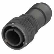
Dimensions
Dimension “L” can be different from the value indicated according to backshells accessories, wires size and some special insert configurations.
214 Go online for data sheets & assembly instructions. Visit www.radiall.com/vansystem and enter the part number. CVBS SHELL
L ØB Ø D1 Ø D2 ØD3 L2 3.5 ØQ Shell size ØQ Max ØB ±0.2 ØD1 ±0.2 ØD2 ±0.2 ØD3 ±0.2 L L2 ±0.2 10SL 23.3 20 8.6 18.5 16.3 66 18 14S 29.5 24 10.6 22 20 66 17.6 16S 33 27 10.4 25 23 66 20.7 16 33 27 13.5 25 23 75.5 20.8 18 37 30 14.5 28 24.5 75.5 20.8 20 41 32 18.4 32 28.5 75.5 20.8 22 43 37 20.7 34 30.5 75.5 20.8 24 48 40 24.6 38.5 34.5 81 20.7 28 53 46 25 40 36 81 21.8 32 60 52 33.3 48 44 82 20.7 36 66.2 58 38.5 55 51 82 20.7 40 72.4 63.8 46 62 58 83 21.8
in mm
CVBS - Bayonet Connector with protected mating ramps
The accessories for this class are not always available in stock for all sizes; we suggest you consult our Sales Office for availability
Contact Gender
GV Connector Class
With waterproof O-ring (IP67***)
with waterproof O-ring and grommet (IP67***) T Connector Modification** T With plastic caps 20-27 Insert Arrangement Size - Type
Socket contacts
Pin contacts
Polarization Code** Alternate Positions CR Contact Termination
Solder contacts
Crimp contacts LC Less contacts CD5 Contact Plating
Silver plating CD5 Gold plating
F5 Electroless nickel (*) F7 Black epoxy varnish (*)
F16 CCF - Black passivation (*) - conductive F26 hard anodization (*)
Modification Code**
215 Go online for data sheets & assembly instructions. Visit www.radiall.com/vansystem and enter the part number.
SHELL
Shell
CVBS
Series Code Shell Type Connector Class
finish
RF CVBS 96GVT 20-27SX CR CD5 F7 N RF CVBS 96 GV 20-27 S X CR CD5 F7 N T Shell Material (*) RoHS compliance (**) If required ***
67
EN 60529 GV
P/N Sample:
Protection degree: IP
(only in the mating area with mated connectors) according to
-
V
S
RF
Code CVBS
Shell
- Aluminum 96 Shell Type 96 Plug
grounding finger
Backshell Gasket Rear Nut Conical Ring Grommet cone (GV Class only) Grommet (GV Class only) RF Insulating material
Chloroprene rubber
Fluoride rubber
Silicone rubber
Fire resistant rubber CVBS Series
Bayonet Connector with protected mating ramps
Material
Connector with
AGV
F7 Shell finish
GV
S
S
P
X
-
CR
-
N
N
S
Consult our sales office
CVBS - Bayonet Connector with protected mating ramps
Plug Connector (96) with Backshell Class (SB)
Connector provided with grounding finger to guarantee shielding; These classes of connectors are provided with backshell for shield hose and heat shrink tubing termination. It comes complete with conical protection spring, also suitable for thin shield braid. Two piece backshell includes nut for shell tightening. Internal serration prevents backshell rotation and allows easy assembling after contacts are inserted.
Grounding finger
Dimensions in mm
Dimension “L” can be different from the value indicated according to backshells accessories, wires size and some special insert configurations.
216 Go online for data sheets & assembly instructions. Visit www.radiall.com/vansystem and enter the part number. CVBS SHELL
L ØB Ø D1 Ø D2 ØD3 L2 3.5 ØQ Shell size ØQ Max ØB ±0.2 ØD1 ±0.2 ØD2 ±0.2 ØD3 ±0.2 L L2 ±0.2 10SL 23.3 22.5 8.6 18.5 16.3 56 18 14S 29.5 26.1 10.6 22 20 56 17.6 16S 33 29 10.4 25 23 56 20.7 16 33 29 13.5 25 23 69 20.8 18 37 33.5 14.5 28 24.5 70 20.8 20 41 37 18.4 32 28.5 71 20.8 22 43 41 20.7 34 30.5 71 20.8 24 48 46 24.6 38.5 34.5 73 20.7 28 53 51 25 40 36 75 21.8 32 60 58 33.3 48 44 75 20.7 36 66.2 61 38.5 55 51 75 20.7 40 72.4 69 46 62 58 76 21.8
CVBS - Bayonet Connector with protected mating ramps
The accessories for this class are not always available in stock for all sizes; we suggest you consult our Sales Office for availability
Contact Termination
Solder contacts CR Crimp contacts LC Less contacts CD5 Contact Plating
F5 Electroless nickel (*)
Black epoxy varnish (*) F16 CCF - Black passivation (*) - conductive F26 hard anodization (*)
217 Go online for data sheets & assembly instructions. Visit www.radiall.com/vansystem and enter the part number.
SHELL
Shell finish
CVBS
Series Code Shell Type Connector Class
RF CVBS 96SBT 20-27SX CR CD5 F7 N RF CVBS 96 SB 20-27 S X CR CD5 F7 N T Shell Material
***
GV Two piece backshell Gasket Rear Nut Conical Ring Grommet cone Grommet (#)
-
rubber V
rubber S
rubber RF Fire
rubber
Code CVBS Bayonet
Shell
- Aluminum 96 Shell Type 96 Plug Connector with grounding finger
SB
T
20-27
Size
S
S
P
X
CR
F7 Shell finish
N
N
S
P/N Sample:
(*) RoHS compliance (**) If required
Protection degree: IP 67 (only in the mating area with mated connectors) according to EN 60529
In some sizes the grommet cone is not needed RF Insulating material
Chloroprene
Fluoride
Silicone
resistant
CVBS Series
Connector with protected mating ramps
Material
SB Connector Class
With waterproof O-ring and grommet (IP67***)# T Connector Modification**
With plastic caps
Insert Arrangement
- Type
Contact Gender
Socket contacts
Pin contacts
Polarization Code** Alternate Positions
-
- Silver plating CD5 Gold plating
F7
Modification Code**
Consult our sales office
CVBS
- Bayonet Connector with protected mating ramps
Plug Connector (96) with Backshell Class (AMK - MK)
Connector provided with grounding finger to guarantee shielding; Connectors provided with gasket and iris spring connected to one another by an internal ring. The iris spring is used to connect multicore jacketed cables or jacketed hoses. An additional gasket added outside of the central body guarantees the complete watertightness. Clamping range on the dimension table has to be chosen according to the cable size and its shielding and specified in the connector P/N.
Dimension “L” can be different from the value indicated according to backshells accessories, wires size and some special insert configurations.
* Must be specified in the connector ** Clamping range to be verified with cable section. Please consult our Sales Office.
218 Go online for data sheets & assembly instructions. Visit www.radiall.com/vansystem and enter the part number. CVBS SHELL
L ØQ ØB Shell size ØQ ØB L 10SL 23.3 20 116 14S 29.5 24 116 16S 33 27 116 16 33 27 148 18 37 30 151 20 41 32 151 22 43 37 151 24 48 40 154 28 53 45 154 32 60 52 158 36 66.2 58 162 40 72.4 63.8 167
Dimensions in mm
Type * Clamping Range ** max min 01 6 3 02 9.5 5 03 13 8.5 04 16.5 12 05 20 15.5 06 23.5 19 07 27 22.5 08 30.5 26 09 34 29.5 10 37.5 33 11 41 36.5 12 44.5 40 13 48 43.5 14 51.5 47 Grounding finger
CVBS - Bayonet Connector with protected mating ramps
Clamping Range
Connector
Contact Termination
Solder contacts
Crimp contacts
Less contacts CD5 Contact Plating
Silver plating CD5 Gold plating
F5 Electroless nickel (*)
Black epoxy varnish (*) F16 CCF - Black passivation (*) - conductive
hard anodization (*)
219 Go online for data sheets & assembly instructions. Visit www.radiall.com/vansystem and enter the part number.
SHELL Series Code Shell Type Shell finish
CVBS
The
for this class are not always available in stock for all sizes; we suggest you consult our Sales Office for availability Backshell Grommet cone (MK Class only) Grommet (MK Class only) Gasket P/N Sample: RF CVBS 96MKT01 20-27SX CR CD5 F7 N RF CVBS 96 MK 20-27 S X CR CD5 F7 N T (*)
required ***
(#)
the
needed Gasket Internal Ring xx Clamping Range Iris Spring Rear Nut Gasket RF
-
rubber V Fluoride rubber S
RF Fire
rubber CVBS Series Code CVBS Bayonet Connector
protected mating
Shell Material - Aluminum 96 Shell Type 96 Plug
MK
AMK
MK
xx
xx
T
Modification** T
20-27
Size
S
S
P
X
CR
-
CR
F7 Shell finish
accessories
RoHS compliance (**) If
Protection degree: IP 67 (only in the mating area with mated connectors) according to EN 60529
In some sizes
grommet cone is not
Insulating material
Chloroprene
Silicone rubber
resistant
with
ramps
Connector with grounding finger
Connector Class
with waterproof O-ring (IP67***)
With waterproof O-ring and grommet (IP67***)#
Type
With plastic caps
Insert Arrangement
- Type
Contact Gender
Socket contacts
Pin contacts
Polarization Code** Alternate Positions
LC
-
N
N
S
F7
F26
Modification Code**
Consult our sales office
CVBS - Bayonet Connector with protected mating ramps
Plug Connector (08) with 90° Elbow Class (A - DA - RA)
Connector with 90° elbow provided with an external thread suitable for MS3057…A or C type Cable-Clamps (to be ordered separately).
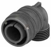
Dimensions in mm
Dimension “L” can be different from the value indicated according to backshells accessories, wires size and some special insert configurations.
220 Go online for data sheets
Visit www.radiall.com/vansystem and enter the part number. CVBS SHELL
& assembly instructions.
ØQ L N H2 H1 Shell size ØQ ±0.2 L max H1 max H2 max N Backshell Thread in inches 10SL 23.3 45.5 27 38.7 5/8”-24 UNEF 14S 29.5 45.5 27 41.3 3/4”-20 UNEF 16S 33 47 29 44.9 7/8”-20 UNEF 16 33 56.5 29 44.9 7/8”-20 UNEF 18 37 57.5 31 48.1 1”-20 UNEF 20 41 60 33 51.7 1” 3/16-18 UNEF 22 43 62.5 35 55.3 1” 3/16-18 UNEF 24 48 65.5 38 59.8 1” 7/16-18 UNEF 28 53 65.5 40 65 1” 7/16-18 UNEF 32 60 70 46 74.1 1” 3/4-18 UNS 36 66.2 73.5 49 80.3 2”-18 UNS 40 72.4 78.5 53 87.6 2”1/4-16 UN
CVBS - Bayonet Connector with protected mating ramps
Elbow Grommet cone (RA Class only) (#) Grommet (RA Class only) Gasket (DA-RA Class only)
RF Insulating material - Chloroprene rubber
Fluoride rubber
Silicone rubber
Fire resistant rubber
CVBS Series Code CVBS Bayonet Connector with protected mating ramps
20-27 Insert Arrangement Size - Type S Contact Gender S Socket contacts P Pin contacts X Polarization Code** Alternate Positions CR Contact Termination
non watertight
with waterproof O-ring (IP67***)
with waterproof O-ring and grommet (IP67***)
T Connector Modification** T With plastic caps
- Solder contacts CR Crimp contacts
LC Less contacts
CD5 Contact Plating - Silver plating
Modification Code**
CD5 Gold plating
F5 Electroless nickel (*)
F7 Black epoxy varnish (*)
F16 CCF - Black passivation (*)conductive
Consult our sales office
RoHS compliance (**) If required *** Protection degree: IP 67 (only in the mating area with mated connectors) according to EN 60529
221 Go online for data sheets & assembly instructions. Visit www.radiall.com/vansystem and enter the part number.
SHELL N N
CVBS
(#)
some sizes the grommet cone
not needed
RF CVBS 08DAT 20-27SX CR CD5 F7 N
Shell Type
Class Shell finish RF CVBS 08 DA 20-27 S X CR CD5 F7 N T
90°
In
is
P/N Sample:
Series Code
Connector
(*)
V
S
RF
08
A
DA
RA
Shell Material - Aluminum 08 Shell Type
Plug Connector with 90° elbow DA Connector Class
(#)
F7
Shell finish
N
S
N
CVBS - Bayonet Connector with protected mating ramps
Plug Connector (08) with 90° Elbow Class (AF - F)
Connector with 90° elbow provided with MS3057...A type Cable-Clamp and bushing MS3420... (for single wire)
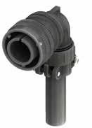
Dimension “L” can be different from the value indicated according to backshells accessories, wires size and some special insert configurations. Dimensions
222 Go online for data sheets & assembly instructions. Visit www.radiall.com/vansystem and enter the part number. CVBS SHELL
L H2 H1 A F Ø ØQ Shell size ØQ ±0.2 L max H1 max H2 max A max ØF cable max dimension 10SL 23.3 45.5 39 50.7 22.5 5.6 14S 29.5 45.5 39 53.3 28 7.9 16S 33 47 42.5 58.4 30 11 16 33 56.5 42.5 58.4 30 11 18 37 57.5 47 64.1 31.7 14.2 20 41 60 47.5 66.2 37.5 15.8 22 43 62.5 49.5 69.8 37.5 15.8 24 48 65.5 53.5 75.3 43.5 19 28 53 65.5 55.5 80.5 43.5 19 32 60 70 61.5 89.6 51.7 23.8 36 66.2 73.5 64.5 95.8 58.5 31.7 40 72.4 78.5 82 116.6 68.5 34.9
in mm
IP54
CVBS - Bayonet Connector with protected mating ramps
Insulating material - Chloroprene rubber
Fluoride rubber
Silicone rubber
resistant rubber
Contact Gender S Socket contacts P Pin contacts X Polarization Code** Alternate Positions CR Contact Termination
- Solder contacts CR Crimp contacts
LC Less contacts
CD5 Contact Plating - Silver plating
CD5 Gold plating
F5 Electroless nickel (*) F7 Black epoxy varnish (*)
F16 CCF - Black passivation (*) - conductive
Consult our sales office
223 Go online for data sheets & assembly instructions. Visit www.radiall.com/vansystem and enter the part number.
SHELL H A F Ø A F Ø
CVBS
(#)
RF CVBS 08AFT 20-27SX CR CD5 F7 N Series Code Shell Type Connector Class Shell finish RF CVBS 08 AF 20-27 S X CR CD5 F7 N T
V
S
Series Code CVBS Bayonet Connector
protected mating ramps Shell Material - Aluminum 08 Shell Type 08 Plug Connector with 90° elbow AF
Class AF with waterproof O-ring
F with waterproof O-ring and grommet
(#)
T With
caps
Size - Type
(*) RoHS compliance
In some sizes the grommet cone is not needed P/N Sample:
Grommet cone (F Class only) Grommet (F Class only) Gasket Cable-Clamp MS3057...A bushing MS3420 (**) If required 90° Elbow RF
RF Fire
CVBS
with
Connector
(IP54)
(IP54)
T Connector Modification**
plastic
20-27 Insert Arrangement
S
F7
finish
Shell
N
N
S
Modification Code**
CVBS - Bayonet Connector with protected mating ramps
Plug Connector (08) with 90° Elbow Class (AC - ACF)
Connector with 90° elbow provided with MS3057...C type Cable-Clamp (for jacketed cable)
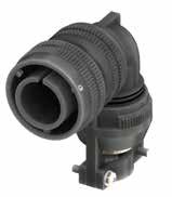
224 Go online for data sheets & assembly instructions. Visit www.radiall.com/vansystem and enter the part number. CVBS SHELL
L H2 H1 A Ø F ØQ Shell size ØQ ±0.2 L max H1 max H2 max A max ØF max cable dimension Min Max 10SL 23.3 45.5 51 62.7 23 2.4 7.9 14S 29.5 45.5 51 65.3 26 5.8 11.2 16S 33 47 54 69.9 28.5 8 13.5 16 33 56.5 54 69.9 28.5 8 13.5 18 37 57.5 58.5 75.6 32 9.6 15.9 20 41 60 59.5 78.2 37.5 11.3 19 22 43 62.5 61.5 81.8 37.5 11.3 19 24 48 65.5 71.5 93.3 43.5 15.5 23.8 28 53 65.5 73.5 98.5 43.5 15.5 23.8 32 60 70 84 112.1 54 23.4 31.8 36 66.2 73.5 91.5 122.8 58 25.4 35 40 72.4 78.5 98 132.6 63.5 30 41.3 Dimension
Dimensions in mm IP67
“L” can be different from the value indicated according to backshells accessories, wires size and some special insert configurations.
CVBS - Bayonet Connector with protected mating ramps
RF Insulating material - Chloroprene rubber V Fluoride rubber S Silicone rubber RF Fire resistant rubber
CVBS Series Code CVBS Bayonet Connector with protected mating ramps Shell Material - Aluminum
Connector with 90° elbow
ACF Connector Class AC with waterproof O-ring (IP67)
with waterproof O-ring and grommet (IP67) (#)
T Connector Modification** T With plastic caps 20-27 Insert Arrangement
S Contact Gender S Socket contacts P Pin contacts X Polarization Code** Alternate Positions
CR Contact Termination
- Solder contacts
CR Crimp contacts
LC Less contacts
CD5 Contact Plating - Silver plating
CD5 Gold plating F7 Shell finish
F5 Electroless nickel (*)
F7 Black epoxy varnish (*)
F16 CCF - Black passivation (*) - conductive N Modification Code**
Consult our sales office
225 Go online for data sheets &
Visit www.radiall.com/vansystem and enter the part number.
SHELL
assembly instructions.
CVBS
(*) RoHS compliance (#) In some sizes the grommet cone is not needed
08ACFT
CR CD5
N
Shell Type
Class Shell finish RF CVBS 08 ACF 20-27 S X CR CD5 F7 N T (**) If required H Grommet cone
Grommet
Gasket Cable-Clamp MS3057...C 90° Elbow
P/N Sample: RF CVBS
20-27SX
F7
Series Code
Connector
(ACF Class only)
(ACF Class only)
08 Shell Type 08 Plug
ACF
Type
Size -
N
S
CVBS - Bayonet Connector with protected mating ramps
Plug Connector (08) with 90° Elbow Class (ACB)
Connector with 90° elbow provided with MS3057...C type Cable-Clamp and bushing MS 3420A (for jacketed cable)
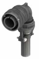
226 Go online for data sheets & assembly instructions. Visit www.radiall.com/vansystem and enter the part number. CVBS SHELL
L H2 H1 A F Ø ØQ Shell size ØQ ±0.2 L max H1 max H2 max A max ØF max cable dimension 10SL 23.3 45.5 51 62.3 23 5.6 14S 29.5 45.5 51 65.3 26 7.9 16S 33 47 54 69.9 28.5 11.1 16 33 56.5 54 69.9 28.5 11.1 18 37 57.5 58.5 75.6 32 11.1 20 41 60 59.5 78.2 37.5 13.7 22 43 62.5 61.5 81.8 37.5 13.7 24 48 65.5 71.5 93.3 43.5 19 28 53 65.5 73.5 98.5 43.5 19 32 60 70 84 112.1 54 23.8 36 66.2 73.5 91.5 122.8 58 28.5 40 72.4 78.5 98 132.6 63.5 31.8 Dimension
can be different from the value indicated according to backshells accessories, wires size
some special insert configurations. Dimensions in mm
“L”
and
CVBS - Bayonet Connector with protected mating ramps
Series Code Shell Type Connector Class Shell finish RF CVBS 08 ACB
Gasket
RF Insulating material - Chloroprene rubber
V Fluoride rubber S Silicone rubber RF Fire resistant rubber
CVBS Series Code CVBS Bayonet Connector with protected mating ramps
Shell Material - Aluminum
08 Shell Type 08 Plug Connector with 90° elbow
ACB Connector Class ACB with waterproof O-ring
T Connector Modification** T With plastic caps
20-27 Insert Arrangement Size - Type
P/N Sample: RF CVBS 08ACBT 20-27SX CR CD5 F7 N
Cable-Clamp MS3057...C bushing MS3420A 90° Elbow
S Contact Gender S Socket contacts P Pin contacts
X Polarization Code** Alternate Positions
CR Contact Termination
- Solder contacts
CR Crimp contacts
LC Less contacts
CD5 Contact Plating - Silver plating
F7 Shell finish
CD5 Gold plating
F5 Electroless nickel (*)
F7 Black epoxy varnish (*)
F16
N Modification Code** N
CCF - Black passivation (*) - conductive
Consult our sales office S
(*) RoHS compliance
(**) If required
227 Go online for data
Visit www.radiall.com/vansystem and enter the part number.
SHELL
sheets & assembly instructions.
CVBS
CR CD5
N
20-27 S X
F7
T
CVBS - Bayonet Connector with protected mating ramps
Plug Connector (08) with 90° Elbow Class (DA...M - RA...M - DA...PG - RA...PG)
Connector with 90° elbow provided with an internal Metric or PG thread suitable for Cable Glands or conduit adapters.
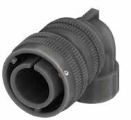
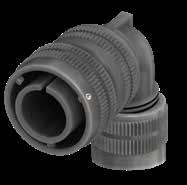
228 Go online for data sheets
assembly instructions. Visit www.radiall.com/vansystem and enter the part number. CVBS SHELL
&
L N H2 H1 N H2 H1 Z Z ØQ Dimension
can be different from the value indicated according to backshells accessories, wires size and some special insert configurations. Dimensions in mm Without adapter With adapter Shell size ØQ ±0.2 L max Z min H1 max H2 max N Backshell Thread Z min H1 max H2 max N Thread Metric PG Metric PG 10SL 23.3 45.5 7 26 40.3 M16 PG9 12 56 68 M12-M20 PG7-PG11-PG16 14S 29.5 45.5 7 26 40.3 M16 PG9 12 56 70.3 M12-M20 PG7-PG11-PG16 16S 33 47 - - - - - 6.5 58 73.9 M16 PG11-PG13,5-PG16 16 33 56.5 - - - - - 6.5 58 73.9 M16 PG11-PG13,5-PG16 18 37 57.5 7 31 48.1 M20 PG16 12 60 75.2 M25 PG13.5-PG21 20 41 60 7 33 51.7 M25 - 12 62 80.7 M16-M20-M32 PG13.5-PG16-PG21-PG29 22 43 62.5 7 35 55.3 M25 PG21 12 65 85.3 M16-M20-M32 PG13.5-PG16-PG29 24 48 65.5 7 38 59.8 M32 PG21 15 69 90.8 M20-M25-M40 PG13.5-PG16-PG29 28 53 65.5 7 40 65 M32 PG21 15 72 97 M20-M25-M40 PG29-PG36 32 60 70 - - - - - 15 78 106.1 M25-M32-M40 PG21-PG29-PG36 36 66.2 73.5 - - - - - 15 81 112.3 M32-M40 PG21-PG29-PG36 40 72.4 78.5 - - - - - 15 85 119.6 M32-M40-M50 PG29-PG36-PG42
“L”
CVBS - Bayonet Connector with protected mating ramps
Backshell internal thread
RF Insulating material - Chloroprene rubber
Fluoride rubber
Silicone rubber
Fire resistant rubber
ramps
Plug Connector with 90° elbow DA Connector Class
with waterproof O-ring (IP67***) RA with waterproof O-ring and grommet (IP67***) (#)
T Connector Modification** T With plastic caps
20-27 Insert Arrangement Size - Type
S Contact Gender S Socket contacts P Pin contacts
Alternate Positions
M12 Backshell internal thread M Provided with an internal Metric thread
PG Provided with an internal PG thread CR Contact Termination - Solder contacts
CR Crimp contacts
LC Less contacts
CD5 Contact Plating - Silver plating
CD5 Gold plating
F5 Electroless nickel (*)
F7 Black epoxy varnish (*)
F16 CCF - Black passivation (*)conductive
Modification Code** N Consult our sales office S
In some sizes the grommet cone is not needed
229 Go online for data sheets & assembly instructions. Visit www.radiall.com/vansystem and enter the part number.
SHELL
CVBS
(#)
Shell finish RF CVBS 08 DA 20-27 S X CR CD5 F7 N T M12 B Ø Z *2
90°
P/N Sample: RF CVBS 08DAT 20-27SX M12 CR CD5 F7 N Series Code Shell Type Connector Class
Elbow Grommet cone (RA..M RA..PG Class only) (#)
Grommet (RA..M RA..PG Class only) Gasket Adapter (if specified) Gasket (*) RoHS compliance (**) If required *** Protection degree: IP 67 (only in the mating area with mated connectors) according to EN 60529
V
S
RF
08
08
CVBS Series Code CVBS Bayonet Connector with protected mating
Shell Material - Aluminum
Shell Type
DA
X Polarization Code**
F7 Shell finish
N
CVBS - Bayonet Connector with protected mating ramps
Plug Connector (98) with 90° Elbow Class (AC - ACF)
Connector provided with grounding finger to guarantee shielding; with 90° elbow provided with MS3057...C type Cable-Clamp (for jacketed cable)
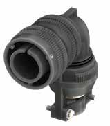
230 Go online for data sheets & assembly instructions. Visit www.radiall.com/vansystem and enter the part number. CVBS SHELL
L H2 H1 A Ø F ØQ Dimension “L” can be different from the value indicated according to backshells accessories, wires size and some special insert configurations. Dimensions in mm IP67
Shell size ØQ ±0.2 L max H1 max H2 max A max ØF max cable dimension Min Max 10SL 23.3 45.5 51 62.7 23 2.4 7.9 14S 29.5 45.5 51 65.3 26 5.8 11.2 16S 33 47 54 69.9 28.5 8 13.5 16 33 56.5 54 69.9 28.5 8 13.5 18 37 57.5 58.5 75.6 32 9.6 15.9 20 41 60 59.5 78.2 37.5 11.3 19 22 43 62.5 61.5 81.8 37.5 11.3 19 24 48 65.5 71.5 93.3 43.5 15.5 23.8 28 53 65.5 73.5 98.5 43.5 15.5 23.8 32 60 70 84 112.1 54 23.4 31.8 36 66.2 73.5 91.5 122.8 58 25.4 35 40 72.4 78.5 98 132.6 63.5 30 41.3
Grounding finger
CVBS - Bayonet Connector with protected mating ramps
RF Insulating material
CVBS Series Code
- Chloroprene rubber V Fluoride rubber S Silicone rubber RF Fire resistant rubber
Bayonet Connector with protected mating ramps
Connector
ACF Connector Class AC with waterproof O-ring (IP67) ACF with waterproof O-ring and grommet (IP67) (#)
T Connector Modification** T With plastic caps 20-27 Insert Arrangement
Size - Type
S Contact Gender S Socket contacts
P Pin contacts
X Polarization Code** Alternate Positions
CR Contact Termination
- Solder contacts
CR Crimp contacts
LC Less contacts
CD5 Contact Plating - Silver plating
CD5 Gold plating F16 Shell finish F16
CCF - Black passivation (*) - conductive N Modification Code** N Consult our sales office S
In some sizes the grommet cone is not needed
(*) RoHS compliance
231 Go online for data sheets & assembly instructions. Visit www.radiall.com/vansystem and enter the part number.
SHELL
CVBS
(#)
CVBS 98ACFT 20-27SX CR CD5 F16 N
Shell Type
Class Shell finish RF CVBS 98 ACF 20-27 S X CR CD5 F16 N T (**) If required H
cone
Class only) Grommet
Gasket
90°
P/N Sample: RF
Series Code
Connector
Grommet
(ACF
(ACF Class only)
Cable-Clamp MS3057...C
Elbow
98
98
CVBS
Shell Material - Aluminum
Shell Type
Plug
with grounding finger with 90° elbow
CVBS - Bayonet Connector with protected mating ramps
Plug Connector (98) with 90° Elbow Class (DA...M - RA...M - DA...PG - RA...PG)
Connector provided with grounding finger to guarantee shielding; with 90° elbow provided with an internal Metric or PG thread suitable for Cable Glands or conduit adapters.
Grounding finger
232 Go online for data sheets
assembly instructions. Visit www.radiall.com/vansystem and enter the part number. CVBS SHELL
&
L N H2 H1 N H2 H1 Z Z ØQ Without adapter With adapter Shell size ØQ ±0.2 L max Z min H1 max H2 max N Backshell Thread Z min H1 max H2 max N Thread Metric PG Metric PG 10SL 23.3 45.5 7 26 40.3 M16 PG9 12 56 68 M12-M20 PG7-PG11-PG16 14S 29.5 45.5 7 26 40.3 M16 PG9 12 56 70.3 M12-M20 PG7-PG11-PG16 16S 33 47 - - - - - 6.5 58 73.9 M16 PG11-PG13,5-PG16 16 33 56.5 - - - - - 6.5 58 73.9 M16 PG11-PG13,5-PG16 18 37 57.5 7 31 48.1 M20 PG16 12 60 75.2 M25 PG13.5-PG21 20 41 60 7 33 51.7 M25 - 12 62 80.7 M16-M20-M32 PG13.5-PG16-PG21-PG29 22 43 62.5 7 35 55.3 M25 PG21 12 65 85.3 M16-M20-M32 PG13.5-PG16-PG29 24 48 65.5 7 38 59.8 M32 PG21 15 69 90.8 M20-M25-M40 PG13.5-PG16-PG29 28 53 65.5 7 40 65 M32 PG21 15 72 97 M20-M25-M40 PG29-PG36 32 60 70 - - - - - 15 78 106.1 M25-M32-M40 PG21-PG29-PG36 36 66.2 73.5 - - - - - 15 81 112.3 M32-M40 PG21-PG29-PG36 40 72.4 78.5 - - - - - 15 85 119.6 M32-M40-M50 PG29-PG36-PG42 Dimension
different
value
backshells accessories, wires size
some special insert configurations.
in mm
“L” can be
from the
indicated according to
and
Dimensions
CVBS - Bayonet Connector with protected mating ramps
Insert
contacts
with an internal Metric thread PG Provided with an internal PG thread
Solder contacts
contacts
contacts
plating
Consult our sales office
233 Go online for data sheets & assembly instructions. Visit www.radiall.com/vansystem and enter the part number.
SHELL
CVBS
(#)
RF CVBS 98DAT
CR CD5 F16 N Series
Shell Type
Class Shell finish RF CVBS 98 DA 20-27 S X CR CD5 F16 N T M12 B Ø Z *2
90° Elbow
cone (RA..M RA..PG Class only) (#)
RA..PG Class only) Gasket Adapter
Gasket (*)
-
rubber V Fluoride
S Silicone rubber RF
CVBS Bayonet
Shell Material - Aluminum 98 Shell Type 98 Plug Connector with
90° elbow
DA
RA
M12
M
F16 CCF
N
In some sizes the grommet cone is not needed P/N Sample:
20-27SX M12
Code
Connector
Backshell internal thread
Grommet
Grommet (RA..M
(if specified)
RoHS compliance (**) If required *** Protection degree: IP 67 (only in the mating area with mated connectors) according to EN 60529 RF Insulating material
Chloroprene
rubber
Fire resistant rubber CVBS Series Code
Connector with protected mating ramps
grounding finger with
DA Connector Class
with waterproof O-ring (IP67***)
with waterproof O-ring and grommet (IP67***) (#) T Connector Modification** T With plastic caps 20-27
Arrangement Size - Type S Contact Gender S Socket
P Pin contacts X Polarization Code** Alternate Positions
Backshell internal thread
Provided
CR Contact Termination -
CR Crimp
LC Less
CD5 Contact Plating - Silver plating CD5 Gold
F16 Shell finish
- Black passivation (*)conductive N Modification Code**
S
CVBS - Bayonet Connector with protected mating ramps
Plug Connector with heavy duty coupling nut (65) with Backshell Class (A - DA - RA)
Connector with backshell provided with an external thread suitable for MS3057…A or C type Cable-Clamps (to be ordered separately).
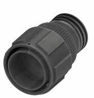
234 Go online for data sheets
Visit www.radiall.com/vansystem and enter the part number. CVBS SHELL
& assembly instructions.
L ØB N ØG1 ØG2 Shell size ØG1 ±0.5 ØG2 ±0.5 L max ØB ±0.2 N Backshell Thread in inches 24 53 47.4 55 40 1” 7/16-18 UNEF 28 60.3 54.8 62 45 1” 7/16-18 UNEF 32 67.1 61.8 62 52 1” 3/4-18 UNS 40 79.1 73.6 64 63.8 2”1/4-16 UN
in mm (*)
availability
this size HEAVY DUTY
Dimension “L” can be different from the value indicated according to backshells accessories, wires size and some special insert configurations. Dimensions
Consult our Sales Office for the
of
CVBS - Bayonet Connector with protected mating ramps
Series Code Shell Type Connector Class
Grommet cone (RA Class only) Grommet (RA Class only)
RF Insulating material - Chloroprene rubber
V Fluoride rubber S Silicone rubber
RF Fire resistant rubber
(DA-RA Class only)
CVBS Series Code CVBS Bayonet Connector with protected mating ramps
Shell Material - Aluminum 65 Shell Type 65 Plug Connector with heavy duty coupling nut
non watertight
DA Connector Class
with waterproof O-ring (IP67***)
with waterproof O-ring and grommet (IP67***)
T Connector Modification** T With plastic caps
20-27 Insert Arrangement Size - Type
S Contact Gender S Socket contacts P Pin contacts X Polarization Code** Alternate Positions
CR Contact Termination
- Solder contacts
CR Crimp contacts
LC Less contacts
CD5 Contact Plating - Silver plating
CD5 Gold plating F7 Shell finish
F5 Electroless nickel (*)
F7 Black epoxy varnish (*)
F16
CCF - Black passivation (*) - conductive
F26 hard anodization (*) N Modification Code**
Consult our sales office
*** Protection degree: IP 67 (only in the mating area with mated connectors) according to EN 60529
P/N Sample: RF CVBS 65DAT 20-27SX CR CD5 F7 N
RoHS compliance (**) If required
235 Go online for data sheets
Visit www.radiall.com/vansystem and enter the part number.
SHELL
& assembly instructions.
CVBS
Shell finish RF CVBS 65 DA 20-27 S X CR CD5 F7 N T
ØB N
Shell Material
Backshell
Gasket
(*)
A
DA
RA
N
S
CVBS - Bayonet Connector with protected mating ramps
Plug Connector with rubber covered coupling nut (06..GG) with Backshell Class (A - DA - RA)
Connector with backshell provided with an external thread suitable for MS3057…A or C type Cable-Clamps (to be ordered separately). Rubber covered coupling nut able to protect against dust and impact.
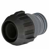
Dimension “L” can be different from the value indicated according to backshells accessories, wires size and some special insert configurations.
236 Go online for data sheets & assembly instructions. Visit www.radiall.com/vansystem and enter the part number. CVBS SHELL
L ØB N ØG1 ØG2
Dimensions in mm Shell size ØG1 ØG2 ØB ±0.2 L max N Backshell
in inches 10SL 33.5 28.5 20 38.5 5/8”-24 UNEF 14S 40.2 34.7 24 45.5 3/4”-20 UNEF 16S 44.4 41.35 27 47.2 7/8”-20 UNEF 16 - - -18 49 43.5 30 56 1”-20 UNEF 20 51.5 46 32 56.5 1” 3/16-18 UNEF 22 56 50.5 37 59 1” 3/16-18 UNEF 24 60 54 40 59 1” 7/16-18 UNEF 28 67 61 45 66 1” 7/16-18 UNEF 32 76 69 52 66 1” 3/4-18 UNS 36 82 73.5 58 66 2”-18 UNS 40 88 80 63.8 68 2”1/4-16 UN GG
Thread
CVBS - Bayonet Connector with protected mating ramps
T Connector Modification**
plastic caps 20-27 Insert Arrangement
- Type S Contact Gender
Socket contacts P Pin contacts X Polarization Code** Alternate Positions CR Contact Termination - Solder contacts CR Crimp contacts
LC Less contacts CD5 Contact Plating
Silver plating
CD5 Gold plating
F5 Electroless nickel (*)
F7 Black epoxy varnish (*)
F16
CCF - Black passivation (*) - conductive
F26 hard anodization (*)
Consult our sales office
237 Go online for data sheets & assembly instructions. Visit www.radiall.com/vansystem and enter the part number.
SHELL
CVBS
RF CVBS 06DAGGT 20-27SX CR CD5 F7 N Series Code Shell Type Connector Class Shell finish RF CVBS 06 DA 20-27 S X CR CD5 F7 N T ØB N
P/N Sample:
cone
Grommet
Class only) Gasket (DA-RA Class only) (*) RoHS compliance (**) If required *** Protection
67
mating
EN 60529 GG
-
V
S
CVBS Series Code CVBS Bayonet Connector
Shell Material - Aluminum 06 Shell Type 06 Plug Connector DA
A non
DA with
O-ring
RA with
GG Rubber
Backshell
Grommet
(RA Class only)
(RA
degree: IP
(only in the
area with mated connectors) according to
RF Insulating material
Chloroprene rubber
Fluoride rubber
Silicone rubber RF Fire resistant rubber
with protected mating ramps
Connector Class
watertight
waterproof
(IP67***)
waterproof O-ring and grommet (IP67***) GG Coupling Nut Type
Covered
T With
Size
S
-
F7 Shell finish
N
N
S
Modification Code**
CVBS - Bayonet Connector with protected mating ramps
Plug Connector with rubber covered coupling nut (06..GG) with Backshell Class (AC - ACF)
Connector provided with backshell, MS3057...C type Cable-Clamp. (for jacketed cable) Rubber covered coupling nut able to protect against dust and impact.
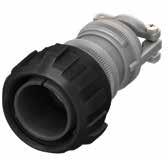
238 Go online for data sheets & assembly instructions. Visit www.radiall.com/vansystem and enter the part number. CVBS SHELL
L ØB A Ø F ØG1 ØG2 Shell size ØG1 ØG2 L max ØB ±0.2 A max ØF cable dimension Min Max 10SL 33.5 28.5 62.5 20 23 2.4 7.9 14S 40.2 34.7 69.5 24 26 5.8 11.2 16S 44.4 41.35 72.2 27 28.5 8 13.5 16 - - - - - -18 49 43.5 83.5 30 32 9.6 15.9 20 51.5 46 83.5 32 37.5 11.3 19 22 56 50.5 85.5 37 37.5 11.3 19 24 60 54 92.5 40 43.5 15.5 23.8 28 67 61 99.5 45 43.5 15.5 23.8 32 76 69 104 52 54 23.4 31.8 36 82 73.5 108.5 58 58 25.4 35 40 88 80 112 63.2 63.5 30 41.3 Dimension “L” can be different from the value indicated according to backshells accessories, wires size and some special insert configurations. Dimensions in mm IP67 GG
CVBS - Bayonet Connector with protected mating ramps
Silicone rubber
contacts
Polarization Code** Alternate Positions CR Contact Termination - Solder contacts CR Crimp contacts LC Less contacts
CD5 Contact Plating - Silver plating
CD5 Gold plating
F5 Electroless nickel (*)
F7 Black epoxy varnish (*)
F16
CCF - Black passivation (*) - conductive F26 hard anodization (*)
239 Go online for data sheets & assembly instructions. Visit www.radiall.com/vansystem and enter the part number.
SHELL
CVBS
(*)
RF CVBS 06ACFGGT 20-27SX CR CD5 F7 N
Type
Class Shell finish RF CVBS 06 ACF 20-27 S X CR CD5 F7 N T
Gasket A Ø F ØB H Cable-Clamp MS3057...C (**) If required GG
V
S
RF
CVBS
Shell
06
Type 06 Plug Connector
AC
ACF
GG
Nut Type GG Rubber
T
Modification** T With plastic caps
Size - Type
X
RoHS compliance P/N Sample:
Series Code Shell
Connector
Backshell Grommet cone (ACF Class only) Grommet (ACF Class only)
RF Insulating material - Chloroprene rubber
Fluoride rubber
Fire resistant rubber CVBS Series Code
Bayonet Connector with protected mating ramps
Material - Aluminum
Shell
ACF Connector Class
with waterproof O-ring (IP67)
with waterproof O-ring and grommet (IP67)
Coupling
Covered
Connector
20-27 Insert Arrangement
S Contact Gender S Socket
P Pin contacts
F7
Shell finish
N
N
S
Modification Code**
Consult our sales office
CVBS - Bayonet Connector with protected mating ramps
Plug Connector with rubber covered coupling nut (06..GG) with Backshell Class (DA..M - RA..M DA..PG - RA..PG)
Connector with backshell provided with an internal Metric or PG thread suitable for Cable Glands or conduit adapters. Rubber covered coupling nut able to protect against dust and impact.
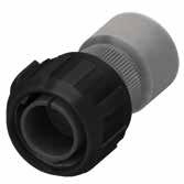
Dimensions in
Dimensions “L1 and L2” can be different from the value indicated according to backshells accessories, wires size and some special insert configurations.
(...) The threads in parentheses are versions on request with
(the
from this
indication). Please consult our sales office for the specific dimensions.
240 Go online for data sheets & assembly instructions. Visit www.radiall.com/vansystem and enter the part number. CVBS SHELL
ØB ØG1 ØG2 N Z L2 L1 Shell size ØG1 ØG2 ØB ±0.2 Z min L1 N Backshell Metric thread L2 M N Backshell PG Thread L2 PG 10SL 33.5 28.5 20 8 22 M12 - M16 32 (PG9) - PG13.5 26 14S 40.2 34.7 24 9 23 M12 - M16 - (M20) - (M25) 30 (PG9) - PG11 - PG13.5 - (PG16) 30 16S 44.4 41.35 27 9 24 (M16) - M20 40 PG13.5 - (PG16) 38 16 - - - - - - - -18 49 43.5 30 9 29 M20 - M25 50 (PG11) - (PG13.5) - PG16 - PG21 50 20 51.5 46 32 9 29 M16 - M20 - M25 - (M32) 50 PG11-PG13.5-PG16-PG21-PG29 50 22 56 50.5 37 10 30 M16 - M20 - M25 - M32 50 PG13.5 - (PG16) - (PG29) 50 24 60 54 40 10 30 M20 - M25 - M32 - M40 50 PG16 - PG21 - PG29 50 28 67 61 45 10 30 (M25) - M32 - M40 63 PG21 - PG29 - PG36 60 32 76 69 52 10 32 (M25) - (M32) - M40 55 PG21 - (PG29) - PG36 60 36 82 73.5 58 13 32 M40 - M50 56 PG29 - (PG36) - (PG42) 65 40 88 80 63.8 13 33 M40 - (M50) - M63 65 PG29 - (PG36) - (PG42) - (PG48) 65 GG
standard
dimensions
Z
different
mm
non
backshell length
L2 and
are
page
CVBS - Bayonet Connector with protected mating ramps
Socket contacts
with an internal Metric thread
with an internal PG thread
Contact Termination - Solder contacts
Crimp contacts
Less contacts
Silver plating CD5 Gold plating
F5 Electroless nickel (*) F7 Black epoxy varnish (*) F16
- Black passivation (*) - conductive
hard anodization (*)
241 Go online for data sheets & assembly instructions. Visit www.radiall.com/vansystem and enter the part number.
SHELL
CVBS
P/N Sample: RF CVBS 06DAGGT 20-27SX M12 CR CD5 F7 N Series Code Shell Type Connector Class Shell finish RF CVBS 06 DA 20-27 S X CR CD5 F7 N T B Ø Z H Z *1 *1 *2 Backshell Grommet cone (RA..M RA..PG Class only) Grommet (RA..M RA..PG Class only) Gasket M12 Backshell internal thread (*) RoHS compliance (**) If required *** Protection degree: IP 67 (only in the mating area
to EN 60529 GG RF
material - Chloroprene rubber V Fluoride rubber S Silicone rubber RF Fire resistant rubber CVBS Series Code CVBS Bayonet Connector with protected mating ramps Shell Material - Aluminum 06 Shell Type 06 Plug Connector DA Connector Class DA with waterproof O-ring (IP67***) RA with waterproof O-ring and grommet (IP67***) GG Coupling Nut Type GG Rubber Covered T
Modification** T With plastic caps 20-27
Size - Type S
S
P
X
M12
M Provided
CR
CR
Contact
-
F7 Shell finish
with mated connectors) according
Insulating
Connector
Insert Arrangement
Contact Gender
Pin contacts
Polarization Code** Alternate Positions
Backshell internal thread
PG Provided
LC
CD5
Plating
N
N
S
CCF
F26
Modification Code**
Consult our sales office
CVBS - Bayonet Connector with protected mating ramps
Plug Connector with rubber covered coupling nut (96..GG) with Backshell Class (A - DA - RA)
Connector provided with grounding finger to guarantee shielding; backshell provided with an external thread suitable for MS3057…A or C type Cable-Clamps (to be ordered separately). Rubber covered coupling nut able to protect against dust and impact.
Grounding finger
Dimension “L” can be different from the value indicated according to backshells accessories, wires size and some special insert configurations.
242 Go online for data sheets & assembly instructions. Visit www.radiall.com/vansystem and enter the part number. CVBS SHELL
L ØB N ØG1 ØG2
Dimensions in mm Shell size ØG1 ØG2 ØB ±0.2 L max N Backshell Thread in inches 10SL 33.5 28.5 20 38.5 5/8”-24 UNEF 14S 40.2 34.7 24 45.5 3/4”-20 UNEF 16S 44.4 41.35 27 47.2 7/8”-20 UNEF 16 - - -18 49 43.5 30 56 1”-20 UNEF 20 51.5 46 32 56.5 1” 3/16-18 UNEF 22 56 50.5 37 59 1” 3/16-18 UNEF 24 60 54 40 59 1” 7/16-18 UNEF 28 67 61 45 66 1” 7/16-18 UNEF 32 76 69 52 66 1” 3/4-18 UNS 36 82 73.5 58 66 2”-18 UNS 40 88 80 63.8 68 2”1/4-16 UN
GG
CVBS - Bayonet Connector with protected mating ramps
RF Insulating material
Covered T Connector Modification** T With plastic caps 20-27 Insert Arrangement Size - Type S Contact Gender S Socket contacts P Pin contacts
resistant rubber
Polarization Code** Alternate Positions CR Contact Termination - Solder contacts CR Crimp contacts
LC Less contacts CD5 Contact Plating
Silver plating
CD5 Gold plating
F5 Electroless nickel (*)
F7 Black epoxy varnish (*)
F16
CCF - Black passivation (*) - conductive
F26 hard anodization (*)
Consult our sales office
243 Go online for data sheets & assembly instructions. Visit www.radiall.com/vansystem and enter the part number.
SHELL
CVBS
RF CVBS 96DAGGT 20-27SX CR CD5 F7 N Series Code
Type Connector Class Shell finish RF CVBS 96 DA 20-27 S X CR CD5 F7 N T ØB N
P/N Sample:
Shell
Grommet
Gasket (DA-RA Class only) (*) RoHS compliance (**)
required ***
60529 GG
V
Code CVBS
Shell Material - Aluminum 96 Shell Type 96 Plug Connector with grounding finger DA
Class A non watertight DA
O-ring
RA
GG Rubber
Backshell
Grommet cone (RA Class only)
(RA Class only)
If
Protection degree: IP 67 (only in the mating area with mated connectors) according to EN
- Chloroprene rubber
Fluoride rubber S Silicone rubber RF Fire
CVBS Series
Bayonet Connector with protected mating ramps
Connector
with waterproof
(IP67***)
with waterproof O-ring and grommet (IP67***) GG Coupling Nut Type
X
-
F7
finish
Shell
N
N
S
Modification Code**
CVBS - Bayonet Connector with protected mating ramps
Plug Connector with rubber covered coupling nut (08..GG) with 90° Elbow Class (A - DA - RA)
Connector with 90° elbow provided with an external thread suitable for MS3057…A or C type Cable-Clamps (to be ordered separately). Rubber covered coupling nut able to protect against dust and impact.
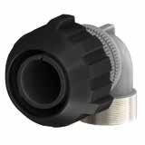
Dimension “L” can be different from the value indicated according to backshells accessories, wires size and some special insert configurations. Dimensions
244 Go online for data sheets
assembly
Visit www.radiall.com/vansystem and enter the part number. CVBS SHELL
&
instructions.
L N H2 H1 ØG1 ØG2 Shell size ØG1 ØG2 L max H1 max H2 max N Backshell Thread in inches 10SL 33.5 28.5 48 27 43.8 5/8”-24 UNEF 14S 40.2 34.7 48 27 47.1 3/4”-20 UNEF 16S 44.4 41.35 51.2 29 51.2 7/8”-20 UNEF 16 - - - - -18 49 43.5 61.5 31 55.5 1”-20 UNEF 20 51.5 46 63.5 33 58.8 1” 3/16-18 UNEF 22 56 50.5 65.5 35 63 1” 3/16-18 UNEF 24 60 54 69 38 68 1” 7/16-18 UNEF 28 67 61 69 40 73.5 1” 7/16-18 UNEF 32 76 69 74 46 84 1” 3/4-18 UNS 36 82 73.5 77.5 49 90 2”-18 UNS 40 88 80 82.5 53 97 2”1/4-16 UN
in mm GG
CVBS - Bayonet Connector with protected mating ramps
Elbow Grommet cone (RA Class only) (#) Grommet (RA Class only) Gasket (DA-RA Class only)
RF Insulating material - Chloroprene rubber V Fluoride rubber S Silicone rubber RF Fire resistant rubber
CVBS Series Code CVBS Bayonet Connector with protected mating ramps Shell Material - Aluminum
DA Connector Class
non watertight
with waterproof O-ring (IP67***)
with waterproof O-ring and grommet (IP67***) (#)
GG Coupling Nut Type GG Rubber Covered
T Connector Modification** T With plastic caps
20-27 Insert Arrangement Size - Type S Contact Gender S Socket contacts P Pin contacts X Polarization Code** Alternate Positions
CR Contact Termination - Solder contacts CR Crimp contacts
LC Less contacts
CD5 Contact Plating - Silver plating
CD5 Gold plating
F5 Electroless nickel (*)
F7 Black epoxy varnish (*)
F16 CCF - Black passivation (*)conductive N Modification Code** N Consult our sales office S
Protection degree: IP 67 (only in the mating area with mated connectors) according to EN 60529
RoHS compliance (**) If required
245 Go online for data sheets & assembly
Visit www.radiall.com/vansystem and enter the part number. CVBS SHELL N N
instructions.
(#)
some sizes the grommet cone is not needed
RF CVBS 08DAGGT 20-27SX CR CD5 F7 N
Type Connector Class Shell finish RF CVBS 08 DA 20-27 S X CR CD5 F7 N T
GG
90°
In
P/N Sample:
Series Code Shell
(*)
***
08 Shell Type 08 Plug Connector with 90° elbow
A
DA
RA
F7 Shell finish
CVBS - Bayonet Connector with protected mating ramps
Plug Connector with rubber covered coupling nut (08..GG) with 90° Elbow Class (AC - ACF)
Connector with 90° elbow provided with MS3057...C type Cable-Clamp (for jacketed cable)
Rubber covered coupling nut able to protect against dust and impact.
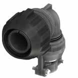
246 Go online for data sheets & assembly instructions. Visit www.radiall.com/vansystem and enter the part number. CVBS SHELL H L B F H1 A ØG1 ØG2
Shell size ØG1 ØG2 L max H1 max H max ØB max A max ØF max cable dimension Min Max 10SL 33.5 28.5 58.5 51 67.8 20 23 2.4 7.9 14S 40.2 34.7 58.5 51 75.1 24 26 5.8 11.2 16S 44.4 41.35 51.2 54 76.2 27 28.5 8 13.5 16 - - - - - - - -18 49 43.5 73.5 58.5 86.5 30 32 9.6 15.9 20 51.5 46 78.8 59.5 90.8 32 37.5 11.3 19 22 56 50.5 81.3 61.5 95 37 37.5 11.3 19 24 60 54 87.3 71.5 103 40 43.5 15.5 23.8 28 67 61 87.3 73.5 108.5 45 43.5 15.5 23.8 32 76 69 97 84 123 52 54 23.4 31.8 36 82 73.5 102.5 91.5 136 58 58 25.4 35 40 88 80 110.3 98 142 63.2 63.5 30 41.3 Dimension
can be different
value indicated according
backshells accessories, wires size
special insert configurations. Dimensions in mm IP67 GG
“L”
from the
to
and some
CVBS - Bayonet Connector with protected mating ramps
RF Insulating material
(ACF Class only)
- Chloroprene rubber
V Fluoride rubber
S Silicone rubber
RF Fire resistant rubber
CVBS Series Code CVBS Bayonet Connector with protected mating ramps Shell Material - Aluminum 08 Shell Type 08 Plug Connector with 90° elbow
ACF Connector Class AC with waterproof O-ring (IP67) ACF with waterproof O-ring and grommet (IP67) (#)
GG Coupling Nut Type GG Rubber Covered
T Connector Modification** T With plastic caps
P/N Sample:
20-27 Insert Arrangement
Size - Type
S Contact Gender S Socket contacts P Pin contacts
X Polarization Code** Alternate Positions
CR Contact Termination
- Solder contacts
CR Crimp contacts
LC Less contacts
CD5 Contact Plating - Silver plating
CD5 Gold plating F7 Shell finish
F5 Electroless nickel (*)
F7 Black epoxy varnish (*)
F16
N Modification Code** N
CCF - Black passivation (*) - conductive
Consult our sales office S
(#) In some sizes the grommet cone is not needed
(*) RoHS compliance
247 Go online for data sheets &
instructions. Visit www.radiall.com/vansystem and enter the part number.
SHELL
assembly
CVBS
CR
N
Code Shell Type
Class Shell finish RF CVBS 08 ACF 20-27 S X CR CD5 F7 N T (**)
required H
Grommet
Gasket Cable-Clamp MS3057...C 90° Elbow GG
RF CVBS 08ACFGGT 20-27SX
CD5 F7
Series
Connector
If
Grommet cone (ACF Class only)
CVBS - Bayonet Connector with protected mating ramps
Plug Connector with rubber covered coupling nut (98..GG) with 90° Elbow Class (A - DA - RA)
Connector with 90° elbow provided with an external thread suitable for MS3057…A or C type Cable-Clamps (to be ordered separately).
Connector provided with grounding finger to guarantee shielding; Rubber covered coupling nut able to protect against dust and impact.
Grounding finger
Dimension “L” can be different from the value indicated according to backshells accessories, wires size and some special insert configurations.
248 Go online for data sheets & assembly instructions. Visit www.radiall.com/vansystem and enter the part number. CVBS SHELL
L N H2 H1 ØG1 ØG2 Shell size ØG1 ØG2 L max H1 max H2 max N Backshell Thread in inches 10SL 33.5 28.5 48 27 43.8 5/8”-24 UNEF 14S 40.2 34.7 48 27 47.1 3/4”-20 UNEF 16S 44.4 41.35 51.2 29 51.2 7/8”-20 UNEF 16 - - - - -18 49 43.5 61.5 31 55.5 1”-20 UNEF 20 51.5 46 63.5 33 58.8 1” 3/16-18 UNEF 22 56 50.5 65.5 35 63 1” 3/16-18 UNEF 24 60 54 69 38 68 1” 7/16-18 UNEF 28 67 61 69 40 73.5 1” 7/16-18 UNEF 32 76 69 74 46 84 1” 3/4-18 UNS 36 82 73.5 77.5 49 90 2”-18 UNS 40 88 80 82.5 53 97 2”1/4-16 UN
Dimensions in mm
GG
CVBS - Bayonet Connector with protected mating ramps
90° Elbow Grommet cone (RA Class only) (#) Grommet (RA Class only) Gasket (DA-RA Class only)
RF Insulating material - Chloroprene rubber V Fluoride rubber S Silicone rubber RF Fire resistant rubber
CVBS Series Code CVBS Bayonet Connector with protected mating ramps Shell Material - Aluminum 98 Shell Type 98 Plug Connector with grounding finger with 90° elbow
DA Connector Class A non watertight DA with waterproof O-ring (IP67***) RA with waterproof O-ring and grommet (IP67***) (#)
GG Coupling Nut Type GG Rubber Covered
T Connector Modification** T With plastic caps
20-27 Insert Arrangement Size - Type S Contact Gender S Socket contacts P Pin contacts X Polarization Code** Alternate Positions
CR Contact Termination
- Solder contacts
CR Crimp contacts
LC Less contacts
CD5 Contact Plating - Silver plating
CD5 Gold plating F7 Shell finish
F5 Electroless nickel (*)
F7 Black epoxy varnish (*)
F16 CCF - Black passivation (*)conductive
N Modification Code** N Consult our sales office S
Protection degree: IP 67 (only in the mating area with mated connectors) according to EN 60529
RoHS
(**) If required
249 Go online for data sheets &
Visit www.radiall.com/vansystem and enter the part number. CVBS SHELL N N
assembly instructions.
(#)
some sizes the grommet cone is not needed
RF CVBS 08DAGGT 20-27SX CR CD5 F7 N
Type
Class Shell finish RF CVBS 98 DA 20-27 S X CR CD5 F7 N T (*)
GG
In
P/N Sample:
Series Code Shell
Connector
compliance
***
CVBS - Bayonet Connector with protected mating ramps
Plug Connector with rubber covered coupling nut (short version) (61..GG) with Backshell Class (A - DA - RA)
Connector with backshell provided with an external thread suitable for MS3057…A or C type Cable-Clamps (to be ordered separately). Rubber covered coupling nut (short version) able to protect against dust and impact.
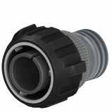
Dimension “L” can be different from the value indicated according to backshells accessories, wires size and some special insert configurations.
250 Go online for data sheets & assembly instructions. Visit www.radiall.com/vansystem and enter the part number. CVBS SHELL
L ØB N ØG1 ØG2
Dimensions in mm Shell size ØG1 ØG2 ØB ±0.2 L max N Backshell Thread in inches 10SL 33.5 28.5 20 38.5 5/8”-24 UNEF 14S 40.2 34.7 24 45.5 3/4”-20 UNEF 16S 44.4 41.35 27 47.2 7/8”-20 UNEF 16 - - -18 49 43.5 30 56 1”-20 UNEF 20 51.5 46 32 56.5 1” 3/16-18 UNEF 22 56 50.5 37 59 1” 3/16-18 UNEF 24 60 54 40 59 1” 7/16-18 UNEF 28 67 61 45 66 1” 7/16-18 UNEF 32 76 69 52 66 1” 3/4-18 UNS 36 82 73.5 58 66 2”-18 UNS 40 88 80 63.8 68 2”1/4-16 UN 61
CVBS - Bayonet Connector with protected mating ramps
resistant
20-27 Insert Arrangement
- Type S Contact Gender S Socket contacts P Pin contacts
Polarization Code** Alternate Positions CR Contact Termination
CD5 Contact Plating
- Solder contacts
Crimp contacts
LC Less contacts
Silver plating
CD5 Gold plating
F5 Electroless nickel (*)
F7 Black epoxy varnish (*)
F16
CCF - Black passivation (*) - conductive
F26 hard anodization (*)
251 Go online for data sheets & assembly instructions. Visit www.radiall.com/vansystem and enter the part number.
SHELL
CVBS
RF CVBS 61DAGGT 20-27SX CR CD5 F7 N Series Code Shell Type Connector Class Shell finish RF CVBS 61 DA 20-27 S X CR CD5 F7 N T ØB N
P/N Sample:
cone
Grommet (RA
only) Gasket (DA-RA Class only) (*) RoHS compliance (**) If required *** Protection
67
EN 60529 GG
-
V
S
RF
CVBS Bayonet
Shell Material - Aluminum 61 Shell Type 61 Plug Connector Rubber
nut
DA
Class A non
DA with
RA
GG
GG Rubber
Backshell
Grommet
(RA Class only)
Class
degree: IP
(only in the mating area with mated connectors) according to
RF Insulating material
Chloroprene rubber
Fluoride rubber
Silicone rubber
Fire
rubber CVBS Series Code
Connector with protected mating ramps
covered coupling
(short version)
Connector
watertight
waterproof O-ring (IP67***)
with waterproof O-ring and grommet (IP67***)
Coupling Nut Type
Covered T Connector Modification** T With plastic caps
Size
X
CR
-
F7 Shell finish
N
N
S
Modification Code**
Consult our sales office
CVBS - Bayonet Connector with protected mating ramps
Plug Connector with rubber covered coupling nut (short version) (61..GG) with Backshell Class (AC - ACF)
Connector provided with backshell, MS3057...C type Cable-Clamp. (for jacketed cable) Rubber covered coupling nut (short version) able to protect against dust and impact.
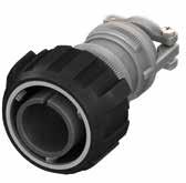
252 Go online for data sheets & assembly instructions. Visit www.radiall.com/vansystem and enter the part number. CVBS SHELL
L ØB A Ø F ØG1 ØG2 Shell size ØG1 ØG2 L max ØB ±0.2 A max ØF cable dimension Min Max 10SL 33.5 28.5 62.5 20 23 2.4 7.9 14S 40.2 34.7 69.5 24 26 5.8 11.2 16S 44.4 41.35 72.2 27 28.5 8 13.5 16 - - - - - -18 49 43.5 83.5 30 32 9.6 15.9 20 51.5 46 83.5 32 37.5 11.3 19 22 56 50.5 85.5 37 37.5 11.3 19 24 60 54 92.5 40 43.5 15.5 23.8 28 67 61 99.5 45 43.5 15.5 23.8 32 76 69 104 52 54 23.4 31.8 36 82 73.5 108.5 58 58 25.4 35 40 88 80 112 63.2 63.5 30 41.3 Dimension
can be different from the value indicated according to backshells accessories,
size
some special insert configurations. Dimensions in mm IP67 61
“L”
wires
and
CVBS - Bayonet Connector with protected mating ramps
Grommet (ACF Class only)
Grommet cone (ACF Class only)
RF Insulating material - Chloroprene rubber V Fluoride rubber S Silicone rubber
RF Fire resistant rubber
Backshell
CVBS Series Code CVBS Bayonet Connector with protected mating ramps
Shell Material - Aluminum 61 Shell Type 61 Plug Connector Rubber covered coupling nut (short version)
ACF Connector Class AC with waterproof O-ring (IP67) ACF with waterproof O-ring and grommet (IP67)
GG Coupling Nut Type GG Rubber Covered
T Connector Modification** T With plastic caps
P/N
20-27 Insert Arrangement Size - Type
S Contact Gender S Socket contacts P Pin contacts
X Polarization Code** Alternate Positions
CR Contact Termination - Solder contacts
CR Crimp contacts
LC Less contacts
CD5 Contact Plating - Silver plating
CD5 Gold plating F7 Shell finish
F5 Electroless nickel (*)
F7 Black epoxy varnish (*)
F16
CCF - Black passivation (*) - conductive
F26 hard anodization (*) N Modification Code** N
Consult our sales office S
(*) RoHS compliance
253 Go online for data sheets &
Visit www.radiall.com/vansystem and enter the part number.
assembly instructions.
SHELL
CVBS
Sample: RF CVBS 61ACFGGT 20-27SX CR CD5 F7 N
Shell finish RF CVBS 61 ACF 20-27 S X CR CD5 F7 N T
Series Code Shell Type Connector Class
Gasket A Ø F ØB H Cable-Clamp MS3057...C (**)
required GG
If
CVBS - Bayonet Connector with protected mating ramps
Plug Connector with rubber covered coupling nut (short version) (61..GG) with Backshell Class (DA..M - RA..M DA..PG - RA..PG)
Connector with backshell provided with an internal Metric or PG thread suitable for Cable Glands or conduit adapters. Rubber covered coupling nut (short version) able to protect against dust and impact.
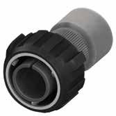
Dimensions “L1 and L2” can be different from the value indicated according to backshells accessories, wires size and some special insert configurations.
Dimensions in mm (...) The threads in parentheses are versions on request with non standard backshell length (the dimensions L2 and Z are different from this page indication). Please consult our sales office for the specific dimensions.
254 Go online for data sheets & assembly instructions. Visit www.radiall.com/vansystem and enter the part number. CVBS SHELL
L2 L1 ØB ØG1 ØG2 N Z 61 Shell size ØG1 ØG2 ØB ±0.2 Z min L1 N Backshell Metric thread L2 M N Backshell PG Thread L2 PG 10SL 33.5 28.5 20 8 21 M12 - M16 32 (PG9) - PG13.5 26 14S 40.2 34.7 24 9 22 M12 - M16 - (M20) - (M25) 30 (PG9) - PG11 - PG13.5 - (PG16) 30 16S 44.4 41.35 27 9 23 (M16) - M20 40 PG13.5 - (PG16) 38 16 - - - - - - - -18 49 43.5 30 9 28 M20 - M25 50 (PG11) - (PG13.5) - PG16 - PG21 50 20 51.5 46 32 9 28 M16 - M20 - M25 - (M32) 50 PG11-PG13.5-PG16-PG21-PG29 50 22 56 50.5 37 10 29 M16 - M20 - M25 - M32 50 PG13.5 - (PG16) - (PG29) 50 24 60 54 40 10 29 M20 - M25 - M32 - M40 50 PG16 - PG21 - PG29 50 28 67 61 45 10 29 (M25) - M32 - M40 63 PG21 - PG29 - PG36 60 32 76 69 52 10 31 (M25) - (M32) - M40 55 PG21 - (PG29) - PG36 60 36 82 73.5 58 13 31 M40 - M50 56 PG29 - (PG36) - (PG42) 65 40 88 80 63.8 13 32 M40 - (M50) - M63 65 PG29 - (PG36) - (PG42) - (PG48) 65
CVBS - Bayonet Connector with protected mating ramps
Backshell internal thread
Grommet cone (RA..M RA..PG Class only) Grommet (RA..M RA..PG Class only)
RF Insulating material - Chloroprene rubber V Fluoride rubber S Silicone rubber RF Fire resistant rubber
CVBS Series Code CVBS Bayonet Connector with protected mating ramps
Material
Aluminum 61 Shell Type 61 Plug Connector Rubber covered coupling nut (short version)
DA Connector Class DA with waterproof O-ring (IP67***) RA with waterproof O-ring and grommet (IP67***) GG Coupling Nut Type GG Rubber Covered T Connector Modification** T With plastic caps 20-27 Insert Arrangement Size - Type S Contact Gender S Socket contacts P Pin contacts X Polarization Code** Alternate Positions M12 Backshell internal thread M Provided with an internal Metric thread
PG Provided with an internal PG thread CR Contact Termination - Solder contacts CR Crimp contacts
LC Less contacts
CD5 Contact Plating - Silver plating
CD5 Gold plating F7 Shell finish
F5 Electroless nickel (*)
F7 Black epoxy varnish (*)
F16 CCF - Black passivation (*) - conductive
F26 hard anodization (*) N Modification Code** N Consult our sales office S
255 Go online for data sheets & assembly
Visit www.radiall.com/vansystem and enter the part number.
SHELL
instructions.
CVBS
CR CD5
N
Shell finish RF CVBS 61 DA 20-27 S X CR CD5 F7 N T B Ø Z H Z *1 *1 *2
P/N Sample: RF CVBS 61DAGGT 20-27SX M12
F7
Series Code Shell Type Connector Class
Backshell
Gasket M12
(*)
***
GG
RoHS compliance (**) If required
Protection degree: IP 67 (only in the mating area with mated connectors) according to EN 60529
Shell
-
CVBS - Bayonet Connector with protected mating ramps
Plug Connector with rubber covered coupling nut (short version) (61..GG) with Backshell Class (AST - ST)
Connector with backshell with internal cable retention system (on request ST1/ST2 with clamps for cable diameter reduction) with an external unef thread. Rubber covered coupling nut (short version) able to protect against dust and impact.
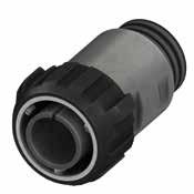
256 Go online for data sheets & assembly instructions. Visit www.radiall.com/vansystem and enter the part number. CVBS SHELL
L ØB N ØG1 ØG2 Shell size ØG1 ØG2 ØB ±0.2 L N Backshell Thread in inches Cable Range ST ST1 ST2 18 49 43.5 30 90 1”-20 UNEF 14-9 9-4 * 20 51.5 46 32 90 1” 3/16-18 UNEF 19-14 14-9 * 22 56 50.5 38 90 1” 3/16-18 UNEF 19-14 14-9 * 24 60 54 45 100 1” 7/16-18 UNEF 23-18 18-13 * 28 67 61 48 100 1” 7/16-18 UNEF 23-18 18-13 * 32 76 69 55 110 1” 3/4-18 UNS 31-25 25-19 19-13 36 82 73.5 58 115 2”-18 UNS 33-25 25-18 * 40 88 80 65 115 2”1/4-16 UN 39-31 31-24 24-16 Dimension
Dimensions in mm * On request (please consult our Sales Office) 61
“L” can be different from the value indicated according to backshells accessories, wires size and some special insert configurations.
CVBS - Bayonet Connector with protected mating ramps
Series Code Shell Type Connector Class Shell finish
Adapter (AST1 - ST1 - AST2 -ST2 Class only)
Grommet (ST - ST1 - ST2 Class only) Gasket
Grommet cone (ST - ST1 - ST2 Class only)
RF Insulating material - Chloroprene rubber V Fluoride rubber S Silicone rubber RF Fire resistant rubber
CVBS Series Code CVBS Bayonet Connector with protected mating ramps
Shell Material - Aluminum
61 Shell Type 61
ST Connector Class
GG Coupling Nut Type GG Rubber Covered T Connector Modification** T With plastic caps
Plug Connector Rubber covered coupling nut (short version)
AST with waterproof O-ring (IP67***)
ST with waterproof O-ring and grommet (IP67***)
AST1 with waterproof O-ring (IP67***)
ST1 with waterproof O-ring and grommet (IP67***)
AST2 with waterproof O-ring (IP67***)
ST2 with waterproof O-ring and grommet (IP67***)
20-27 Insert Arrangement
Size - Type
S Contact Gender S Socket contacts P Pin contacts X Polarization Code** Alternate Positions
CR Contact Termination - Solder contacts
CR Crimp contacts
LC Less contacts
CD5 Contact Plating - Silver plating
F7 Shell finish
CD5 Gold plating
F5 Electroless nickel (*)
F7 Black epoxy varnish (*)
F16
CCF - Black passivation (*) - conductive
F26 hard anodization (*) N Modification Code** N
Consult our sales office S
257 Go online for data sheets & assembly instructions. Visit www.radiall.com/vansystem and enter the part number. CVBS SHELL
Backshell
P/N Sample: RF CVBS 61STGGT 20-27SX CR CD5 F7 N RF CVBS 61 ST 20-27 S X CR CD5 F7 N T (*) RoHS compliance (**) If required *** Protection degree: IP 67
in the mating area with mated connectors) according to EN 60529
(only
Gasket
Backshell
GG
CVBS - Bayonet Connector with protected mating ramps
Plug Connector with rubber covered coupling nut (short version) (61..GG) with Backshell Class (AST..M - ST..M)
Connector with backshell with internal cable retention system (on request ST1/ST2 with clamps for cable diameter reduction) with an internal Metric thread. Rubber covered coupling nut (short version) able to protect against dust and impact.
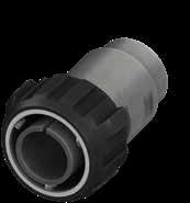
* On request (please consult our Sales Office)
Dimension “L” can be different from the value indicated according to backshells accessories, wires size and some special insert configurations.
258 Go online for data sheets & assembly instructions. Visit www.radiall.com/vansystem and enter the part number. CVBS SHELL
L ØB N ØG1 ØG2
Dimensions in mm
Shell size ØG1 ØG1 ØB ±0.2 L N Backshell Thread Metric Cable Range ST ST1 ST2 18 49 43.5 30 90 M16 - M20 14-9 9-4 * 20 51.5 46 32 90 M20 19-14 14-9 * 22 56 50.5 38 90 M20 19-14 14-9 * 24 60 54 45 100 M25 23-18 18-13 * 28 67 61 48 100 M25 23-18 18-13 * 32 76 69 55 110 M32 - M40 31-25 25-19 19-13 36 82 73.5 58 115 M32 - M40 33-25 25-18 * 40 88 80 65 115 M40 - M50 39-31 31-24 24-16 61
CVBS - Bayonet Connector with protected mating ramps
Series Code Shell Type Connector Class
Adapter (AST1 - ST1 - AST2 -ST2 Class only)
Grommet (ST - ST1 - ST2 Class only) Gasket
Grommet cone (ST - ST1 - ST2 Class only)
RF Insulating material - Chloroprene rubber V Fluoride rubber S Silicone rubber RF Fire resistant rubber
CVBS Series Code
61 Shell Type
ST Connector Class
Bayonet Connector with protected mating ramps
Plug Connector Rubber covered coupling nut (short version)
AST with waterproof O-ring (IP67***)
ST with waterproof O-ring and grommet (IP67***)
AST1 with waterproof O-ring (IP67***)
ST1 with waterproof O-ring and grommet (IP67***)
AST2 with waterproof O-ring (IP67***)
ST2 with waterproof O-ring and grommet (IP67***)
GG Coupling Nut Type GG Rubber Covered T Connector Modification**
20-27 Insert Arrangement
Backshell
Size - Type S Contact Gender S Socket contacts P Pin contacts
Polarization Code** Alternate Positions M Backshell internal thread M Provided with an internal Metric thread
CR Contact Termination - Solder contacts CR Crimp contacts LC Less contacts
CD5 Contact Plating - Silver plating
CD5 Gold plating F7 Shell finish
F5 Electroless nickel (*)
F7 Black epoxy varnish (*)
F16
CCF - Black passivation (*) - conductive
F26 hard anodization (*) N Modification Code** N Consult our sales office
259 Go online for data sheets & assembly instructions. Visit www.radiall.com/vansystem and enter the part number. CVBS SHELL
Shell
finish
P/N Sample: RF CVBS 61STGGT 20-27SX M CR CD5 F7 N RF CVBS 61 ST 20-27 S X CR CD5 F7 N T (*) RoHS compliance (**) If required ***
60529
Protection degree: IP 67 (only in the mating area with mated connectors) according to EN
Gasket
Backshell
M GG
CVBS
Shell Material - Aluminum
61
T With plastic caps
X
S
CVBS - Bayonet Connector with protected mating ramps
Plug Connector with rubber covered coupling nut (short version) (61..GG) with Backshell Class (AST..FS - ST..FS)
Connector with backshell with internal cable retention system (on request ST1/ST2 with clamps for cable diameter reduction) with a special adapter for rubber conduits. Rubber covered coupling nut (short version) able to protect against dust and impact.
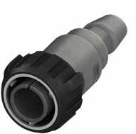
“L” can be different from the value indicated according to backshells accessories, wires size and some special insert configurations.
260 Go online for data sheets & assembly instructions. Visit www.radiall.com/vansystem and enter the part number. CVBS SHELL
ØB Ø 1 A Ø 2 A ØG1 ØG2 L Shell size ØG1 ØG1 ØB ±0.2 L Cable Range ST ST1 ST2 18 49 43.5 30 120 14-9 9-4 * 20 51.5 46 32 120 19-14 14-9 * 22 56 50.5 38 120 19-14 14-9 * 24 60 54 45 125 23-18 18-13 * 28 67 61 48 125 23-18 18-13 * 32 76 69 55 139 31-25 25-19 19-13 36 82 73.5 58 139 33-25 25-18 * 40 88 80 65 139 39-31 31-24 24-16 Dimension
Dimensions
mm *
consult
Office
further details about this dimension
according to conduit size. * * Rubber Conduit not included Backshell Conduit Size ØA1* ØA2* FS2015 20 15 FS2520 25 20 FS2722 27 22 FS3328 33 28 FS3530 35 30 FS4035 40 35 FS4540 45 40 FS5045 50 45 FS5945 59 45
in
On request (please consult our Sales Office) Please
our Sales
for
and
CVBS - Bayonet Connector with protected mating ramps
RF Insulating material
resistant rubber
Connector with protected mating ramps Shell Material
61 Shell Type
Plug Connector Rubber covered coupling nut (short version) ST Connector Class
AST with waterproof O-ring (IP67***)
ST with waterproof O-ring and grommet (IP67***)
AST1 with waterproof O-ring (IP67***)
ST1 with waterproof O-ring and grommet (IP67***)
AST2 with waterproof O-ring (IP67***)
ST2 with waterproof O-ring and grommet (IP67***) T Connector Modification**
Contact Gender
FS Backshell Conduits size
Conduit Size
Socket contacts
Pin contacts
Positions
Provided with a special adapter for rubber conduits
ØA1/ØA2 CR Contact Termination - Solder contacts
CR Crimp contacts
LC Less contacts
CD5 Contact Plating - Silver plating
CD5 Gold plating F7 Shell finish
F5 Electroless nickel (*)
F7 Black epoxy varnish (*)
F16 CCF - Black passivation (*)conductive
F26 hard anodization (*)
Consult our sales office
261 Go online for data sheets & assembly instructions. Visit www.radiall.com/vansystem and enter the part number. CVBS SHELL
Backshell Grommet cone (ST - ST1 - ST2 Class only)
Gasket P/N Sample: RF CVBS 61STGGT 20-27SX FS2015 CR CD5 F7 N (*) RoHS compliance (**) If required *** Protection degree: IP 67 (only in the mating area with mated connectors) according to EN 60529 Gasket
Adapter (AST1 - ST1 - AST2 - ST2 Class only) Series Code Shell Type Connector Class Shell finish RF CVBS 61 ST 20-27 S X CR CD5 F7 N T FS
size 2015 GG
Grommet (ST - ST1 - ST2 Class only)
Backshell
Backshell Conduits
-
V
S
Series
CVBS
-
Chloroprene rubber
Fluoride rubber
Silicone rubber RF Fire
CVBS
Code
Bayonet
Aluminum
61
T With
GG
Nut Type GG Rubber
S
P
X
plastic caps
Coupling
Covered 20-27 Insert Arrangement Size - Type
S
Polarization Code** Alternate
FS
2015
xxxx
N
N
S
Modification Code**
CVBS - Bayonet Connector with protected mating ramps
Plug Connector with rubber covered coupling nut (short version) (81..GG) with 90° Elbow Class (A - DA - RA)
Connector with 90° elbow provided with an external thread suitable for MS3057…A or C type Cable-Clamps (to be ordered separately). Rubber covered coupling nut (short version) able to protect against dust and impact.
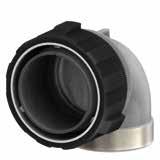
262 Go online for data sheets & assembly instructions. Visit www.radiall.com/vansystem and enter the part number. CVBS SHELL
L N H2 H1 ØG1 ØG2 Shell size ØG1 ØG2 L max H1 max H2 max N Backshell Thread in inches 18 49 43.5 61.5 31 55.5 1”-20 UNEF 20 51.5 46 63.5 33 58.8 1” 3/16-18 UNEF 22 56 50.5 65.5 35 63 1” 3/16-18 UNEF 24 60 54 69 38 68 1” 7/16-18 UNEF 28 67 61 69 40 73.5 1” 7/16-18 UNEF 32 76 69 74 46 84 1” 3/4-18 UNS 36 82 73.5 77.5 49 90 2”-18 UNS 40 88 80 82.5 53 97 2”1/4-16 UN Dimension “L” can be different from the value indicated according to backshells accessories, wires size and some special insert configurations. Dimensions in mm 81
CVBS - Bayonet Connector with protected mating ramps
Elbow Grommet cone (RA Class only) (#) Grommet (RA Class only) Gasket (DA-RA Class only)
RF Insulating material - Chloroprene rubber
Fluoride rubber S Silicone rubber RF Fire resistant rubber
CVBS Series Code CVBS Bayonet Connector with protected mating ramps Shell Material - Aluminum 81 Shell Type 81
Plug Connector with 90° elbow Rubber covered coupling nut (short version)
DA Connector Class A non watertight
with waterproof O-ring (IP67***)
with waterproof O-ring and grommet (IP67***) (#)
GG Coupling Nut Type GG Rubber Covered
T Connector Modification** T With plastic caps
20-27 Insert Arrangement Size - Type S Contact Gender S Socket contacts P Pin contacts X Polarization Code** Alternate Positions
CR Contact Termination
- Solder contacts CR Crimp contacts
LC Less contacts
CD5 Contact Plating - Silver plating
F7 Shell finish
CD5 Gold plating
F5 Electroless nickel (*)
F7 Black epoxy varnish (*)
F16 CCF - Black passivation (*)conductive N Modification Code** N Consult our sales office S
Protection degree: IP 67 (only in the mating area with mated connectors) according to EN 60529
RoHS
(**) If
263 Go online for data sheets & assembly instructions. Visit www.radiall.com/vansystem and enter the part number.
SHELL N N
CVBS
(#) In some sizes the grommet cone is not needed
RF CVBS 81DAGGT 20-27SX CR CD5 F7 N
Type Connector Class Shell finish RF CVBS 81 DA 20-27 S X CR CD5 F7 N T (*)
GG
90°
P/N Sample:
Series Code Shell
compliance
required ***
V
DA
RA
CVBS - Bayonet Connector with protected mating ramps
Plug Connector with rubber covered coupling nut (short version) (81..GG) with 90° Elbow Class (AST..M - ST..M)
Connector with backshell with internal cable retention system (on request ST1/ST2 with clamps for cable diameter reduction) with an internal Metric thread. Rubber covered coupling nut (short version) able to protect against dust and impact.
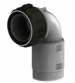
“L”
264 Go online for data sheets & assembly instructions. Visit www.radiall.com/vansystem and enter the part number. CVBS SHELL
L H2 H1 ØG1 ØG2 ØB N Dimension
special
Dimensions in mm * On request (please consult our Sales Office) Shell size ØG1 ØG2 ØB ±0.2 L max H1 H2 N Backshell Thread Metric Cable Range ST ST1 ST2 18 49 43.5 30 61.5 * * M16 - M20 14-9 9-4 * 20 51.5 46 32 63.5 93 119 M20 - M32 19-14 14-9 * 22 56 50.5 38 65.5 * * M20 19-14 14-9 * 24 60 54 45 69 * * M25 23-18 18-13 * 28 67 61 48 69 * * M25 23-18 18-13 * 32 76 69 55 74 * * M32 - M40 31-25 25-19 19-13 36 82 73.5 58 78 120 162 M32 - M40 33-25 25-18 * 40 88 80 65 82 135 180 M40 - M50 39-31 31-24 24-16 81
can be different from the value indicated according to backshells accessories, wires size and some
insert configurations.
CVBS - Bayonet Connector with protected mating ramps
Grommet
ST Connector Class
Grommet
Chloroprene rubber
resistant
Bayonet Connector with protected mating ramps
Plug Connector with 90° elbow Rubber covered coupling nut (short version)
AST with waterproof O-ring (IP67***)
ST with waterproof O-ring and grommet (IP67***)
AST1 with waterproof O-ring (IP67***)
ST1 with waterproof O-ring and grommet (IP67***)
AST2 with waterproof O-ring (IP67***)
ST2 with waterproof O-ring and grommet (IP67***)
20-27 Insert Arrangement
Contact Gender
Socket contacts
Polarization Code** Alternate Positions
Backshell internal thread
Provided with an internal Metric thread
CR Contact Termination - Solder contacts
CR Crimp contacts
LC Less contacts
CD5 Contact Plating - Silver plating
CD5 Gold plating
F5 Electroless nickel (*)
F7 Black epoxy varnish (*)
F16 CCF - Black passivation (*)conductive
F26 hard anodization (*)
Consult our sales office
265 Go online for data sheets & assembly instructions. Visit www.radiall.com/vansystem and enter the part number. CVBS SHELL
Type
Class Shell finish
Series Code Shell
Connector
P/N Sample: RF CVBS 81STGGT 20-27SX M CR CD5 F7 N RF CVBS 81 ST 20-27 S X CR CD5 F7 N T (*) RoHS compliance (**) If required *** Protection degree: IP 67 (only in the mating area with mated connectors) according to EN 60529
ST1
AST2
only) M GG Backshell
Adapter (AST1 -
-
-ST2 Class
cone (ST - ST1 - ST2 Class only)
Gasket Gasket Backshell 90° Elbow Gasket
-
V
S
CVBS
Shell Material - Aluminum
Type 81
(ST - ST1 - ST2 Class only)
RF Insulating material
Fluoride rubber
Silicone rubber RF Fire
rubber CVBS Series Code
81 Shell
GG
Nut Type GG Rubber Covered T
T With plastic caps
Size -
S
S
P
X
M
Coupling
Connector Modification**
Type
Pin contacts
M
F7 Shell finish
N
N
Modification Code**
S
CVBS - Bayonet Connector with protected mating ramps Front Mounting Receptacle (26) unable to Accept Rear Accessories
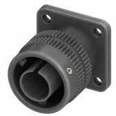
266 Go online for data sheets & assembly instructions. Visit www.radiall.com/vansystem and enter the part number. CVBS SHELL
S L K ØQ L R ØT ØG2 ØG1 S R ØT Shell size L K ±0.2 ØQ R ±0.1 S ±0.3 ØT ±0.2 ØT1 Through holes ØC ±0.2 10SL 37 2.8 23.2 18.2 25.4 3.1 3.4 17 14S 37.2 3.2 29.5 23 30.2 3.1 3.4 20 16S 37.2 3.2 33 24.6 32.5 3.1 3.4 23 16 38.3 3.2 33.6 24.6 32.5 3.1 3.4 23 18 38.3 4 37 27 34.9 3.1 3.4 26.5 20 38.3 4 41 29.4 38.1 3.1 3.4 30 22 38.3 4 43 31.8 41 3.1 3.4 33 24 40.8 4 48 34.9 44.5 3.7 3.9 36 28 41 4 53 39.7 50.8 3.7 3.9 42 32 43.9 4 60 44.5 57 4.4 4.5 48.5 36 45 4 66.2 49.2 63.5 4.4 4.5 55 40 45 4 72.4 55.6 69.8 4.4 4.5 61 Dimension “L” can be different from the value indicated according to wires size and some special insert configurations. Dimensions in mm R ØC ØT 1 Panel cut out
CVBS - Bayonet Connector with protected mating ramps
Insulating material
Front mounting receptacle connector with coupling nut, unable to accept rear accessories T Connector Modification**
With plastic caps
Receptacle connector with threaded holes
Receptacle connector with through holes
Receptacle connector with countersunk holes
Insert Arrangement
Contact Gender
CR Contact Termination
CD5 Contact Plating
Silver plating
Gold plating F7 Shell finish
nickel (*)
Black epoxy varnish (*) F16 CCF - Black passivation (*) - conductive F26 hard anodization (*) G Panel Gasket
Without gasket
With waterproof panel gasket
267 Go online for data sheets & assembly instructions. Visit www.radiall.com/vansystem and enter the part number.
SHELL Series Code Shell Type Shell finish
CVBS
(*) RoHS compliance P/N Sample: RF CVBS 26T 20-27SX CR CD5 F7 G N RF CVBS 26 20-27 S X CR CD5 F7 G N T Shell Material (**) If required RF
- Chloroprene rubber V Fluoride rubber S Silicone rubber RF Fire resistant rubber CVBS Series Code CVBS Bayonet Connector with protected mating ramps Shell
- Aluminum 26
26
T
FF
-
FS
Size
Type
S Socket contacts P Pin contacts X
Code** Alternate
-
CR Crimp
LC Less
DS PCB
Material
Shell Type
20-27
-
S
Polarization
Positions
Solder contacts
contacts
contacts
contacts
-
CD5
-
G
G2
N Consult our sales office S
F5 Electroless
F7
With shielded panel gasket G3 With waterproof shielded panel gasket N Modification Code**
CVBS - Bayonet Connector with protected mating ramps
Front Mounting Receptacle, heavy duty coupling nut (265) unable to Accept Rear Accessories
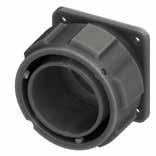
(*) Consult our Sales Office for the availability of this size
268 Go online for data sheets & assembly instructions. Visit www.radiall.com/vansystem and enter the part number. CVBS SHELL
S ØT ØG2 L K L R ØT L ØG1 ØG2 ØG1 S R ØT Shell size L ØG1 ±0.5 ØG2 ±0.5 R ±0.1 S ±0.3 ØT ±0.2 ØT1 Through holes ØC ±0.2 20 * 38.3 46.4 40.9 29.4 38.1 3.1 3.4 30 24 40.8 53 47.4 34.9 44.5 3.7 3.9 36 28 41 60.3 54.8 39.7 50.8 3.7 3.9 42 32 43.9 67.1 61.8 44.5 57 4.4 4.5 48.5 40 45 79.1 73.6 55.6 69.8 4.4 4.5 61 Dimension
can be different
value indicated according
wires size
some special insert configurations. Dimensions in mm R ØC ØT 1 Panel cut out
HEAVY DUTY
“L”
from the
to
and
CVBS - Bayonet Connector with protected mating ramps
Insulating material
T Connector Modification**
20-27 Insert Arrangement
mounting receptacle connector with heavy duty coupling nut, unable to accept rear accessories
With plastic caps
Receptacle connector with threaded holes
Receptacle connector with through holes
Receptacle connector with countersunk holes
- Type S Contact Gender
CR Contact Termination
CD5 Contact Plating
F7 Shell finish
G Panel Gasket
Silver plating
plating
F5 Electroless nickel (*)
F7 Black epoxy varnish (*)
F16
CCF - Black passivation (*) - conductive
F26 hard anodization (*)
Without gasket
With waterproof panel gasket G2 With shielded panel gasket G3 With waterproof shielded panel gasket N Modification Code**
269 Go online for data sheets & assembly instructions. Visit www.radiall.com/vansystem and enter the part number.
SHELL
Shell Type Shell finish
CVBS
Series Code
(*) RoHS compliance
Sample: RF CVBS 265T 20-27SX CR CD5 F7 G N RF CVBS 265 20-27 S X CR CD5 F7 G N T Shell Material (**) If required
- Chloroprene rubber V Fluoride rubber S Silicone
RF Fire
rubber CVBS Series Code CVBS Bayonet Connector with protected mating ramps Shell
Aluminum 265
265
P/N
RF
rubber
resistant
Material -
Shell Type
Front
T
FF
-
FS
S
P Pin contacts X
Size
Socket contacts
Polarization Code** Alternate Positions
-
CR
LC
DS PCB
Solder contacts
Crimp contacts
Less contacts
contacts
-
CD5 Gold
-
G
N
S
Consult our sales office
CVBS - Bayonet Connector with protected mating ramps
Through-Bulkhead Connector (TB)
Available in the following versions: pin-socket contacts, pin-pin or socket-socket contacts.
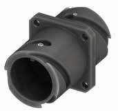
Panel cut out In case of PS contact gender, Socket in Front side. Front side
Dimensions in mm
Dimension “L” can be different from the value indicated according to wires size and some special insert configurations.
270 Go online for data sheets & assembly instructions. Visit www.radiall.com/vansystem and enter the part number. CVBS SHELL
S Ø D M K L R T Ø D P Shell size ØD +0 -0.15 L K ±0.2 M ±0.2 R ±0.1 S ±0.3 ØT ±0.2 ØT1 Threaded holes ØC ±0.2 P Panel Thickness Max Through bulkhead, gasket side mounting connectors 10SL 18.2 37.5 2.8 14.2 18.2 25.4 M4 4.5 19.1 10 14S 24.6 37.5 3.2 14.2 23 30.2 M4 4.5 25.5 9.6 16S 27.4 37.5 3.2 14.2 24.6 32.5 M4 4.5 28.3 9.6 16 27.4 51.4 3.2 19 24.6 32.5 M4 4.5 28.3 13.8 18 30.8 51.4 4 19 27 34.9 M4 4.5 31.7 13 20 34.2 51.6 4 19 29.4 38.1 M4 4.5 35 13 22 37.4 51.4 4 19 31.8 41 M4 4.5 38.3 12.25 24 40.9 51.4 4 20.6 34.9 44.5 M4 4.5 41.8 11.25 28 46.7 51.4 4 20.6 39.7 50.8 M5 5.5 47.6 12.4 32 53.4 51.4 4 22.2 44.5 57 M5 5.5 54.3 9 36 59.6 51.4 4 22.2 49.2 63.5 M5 5.5 60.5 8.3 40 65.5 51.4 4 22.2 55.6 69.8 M5 5.5 66.4 9
R ØC ØT 1
CVBS - Bayonet Connector with protected mating ramps
Connector Modification**
With plastic caps
Receptacle connector with threaded holes
Receptacle connector with through holes
Receptacle connector with countersunk holes 20-27 Insert Arrangement Size - Type PS Contact Gender
CD5 Contact Plating
F7 Shell finish F5 Electroless nickel (*) F7 Black epoxy varnish (*)
F16 CCF - Black passivation (*) - conductive F26 hard anodization (*) G Panel Gasket
Without gasket
With waterproof panel gasket
G2 With shielded panel gasket
G3 With waterproof shielded panel gasket
271 Go online for data sheets & assembly instructions. Visit www.radiall.com/vansystem and enter the part number.
SHELL
Shell
CVBS
Series Code Shell Type
finish
(*)
compliance
Sample: RF CVBS TBT 20-27PSX CD5 F7 G N RF CVBS TB 20-27 PS X CD5 F7 G N T Shell
(**) If required *** On request
-
V Fluoride
S Silicone
RF Fire
CVBS Series Code CVBS Bayonet Connector with protected mating ramps
- Aluminum TB Shell Type TB Through-bulkhead
T
-
RoHS
P/N
Material
RF Insulating material
Chloroprene rubber
rubber
rubber
resistant rubber
Shell Material
connector. T
FP
SS***
X
FS
PS Pin + Socket contacts
Socket + Socket contacts PP Pin + Pin contacts
Polarization Code** Alternate Positions
-
Silver plating CD5 Gold plating
-
G
N
S
N Modification Code**
Consult our sales office
CVBS - Bayonet Connector with protected mating ramps
Dummy Receptacle Connector (05)
Useful to hold the plug connectors when not in use.
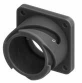
272 Go online for data sheets & assembly instructions. Visit www.radiall.com/vansystem and enter the part number. CVBS SHELL
T K M L ØD S R Dimension
different
value
size
special insert configurations. Dimensions in mm ØT 1 Panel cut out Shell size ØD +0 -0.15 L K ±0.2 M ±0.2 R ±0.1 S ±0.3 ØT ±0.2 ØT1 Through holes 10SL 18.2 17 2.8 14.2 18.2 25.4 3.1 3.4 14S 24.6 17.7 3.2 14.5 23 30.2 3.1 3.4 16S 27.4 17.4 3.2 14.2 24.6 32.5 3.1 3.4 16 27.4 22.2 3.2 19 24.6 32.5 3.1 3.4 18 30.8 23 4 19 27 34.9 3.1 3.4 20 34.2 23 4 19 29.4 38.1 3.1 3.4 22 37.4 23.7 4 19.7 31.8 41 3.1 3.4 24 40.9 24.6 4 20.6 34.9 44.5 3.7 3.9 28 46.7 24.6 4 20.6 39.7 50.8 3.7 3.9 32 53.4 26.2 4 22.2 44.5 57 4.4 4.5 36 59.6 26.2 4 22.2 49.2 63.5 4.4 4.5 40 65.5 26.2 4 22.2 55.6 69.8 4.4 4.5
“L” can be
from the
indicated according to wires
and some
CVBS - Bayonet Connector with protected mating ramps
273 Go online for data sheets & assembly instructions. Visit www.radiall.com/vansystem and enter the part number.
SHELL
CVBS
Series Code Shell Type Shell finish
CVBS
Shell
-
05
05 Dummy
T
T With plastic caps FF
holes - Receptacle
FS
20
CVBS Series Code
Bayonet Connector with protected mating ramps
Material
Aluminum
Shell Type
Receptacle Connector
Connector Modification**
Receptacle connector with threaded
connector with through holes
Receptacle connector with countersunk holes
Shell size
F5 Electroless
(*) F7 Black
CCF
F26
S
(*)
P/N Sample: CVBS 05T 20 F7 N CVBS 05 20 F7 S T Shell Material (**)
required
F7 Shell finish
nickel
epoxy varnish (*) F16
- Black passivation (*) - conductive
hard anodization (*)
Modification Code** S Consult our sales office
RoHS compliance
If
274 Go online for data sheets & assembly instructions. Visit www.radiall.com/vansystem and enter the part number. SHELL
CVBSG - Bayonet Connector with external insulated coating - Shell - Backshell
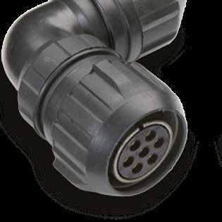
CVBSG series has been modified to design safety connectors. The shells of plug connectors have been rubber jacketed. Accessories in rubber material or with rubber protection are also available for cable retention.
Main characteristics:
• These connectors are particularly suitable for applications with mechanical shock
• Rubber jacket and insulating parts are in accordance with EN 45545-2 standards
• Standard panel receptacle supplied with countersunk holes for easy mating with rubber jacketed nuts
• Accessories made of rubber material or with rubber protection are also available for cable retention
Available in several versions suitable for all applications and manufactured in different materials and finishes:
• Aluminum alloy with different types of protection finishes according to RoHS directives.
connector with threaded holes (to specify for 00/02/05 shell only)
Receptacle connector with through holes (to specify for 03 shell only)
connector with countersunk holes
(Consult our sales office)
275 Go online for data sheets & assembly instructions. Visit www.radiall.com/vansystem and enter the part number.
SHELL
CVBSG
RF CVBSG 00 DA 20-27 S X PG16 CR CD5 F7 G N T
Series Code CVBSG Bayonet Connector with external insulated coating Shell Material - Aluminum 00 Shell Type xx Flange/Plug Shell with ramp/threaded or with nut DA Connector Class xx With backshell T Connector Modification** T With plastic caps FF
FP
FS
PG16 Backshell Conduits size or internal thread - Without internal thread xx Conduits size or internal thread F7 Shell finish F7 Black epoxy varnish (RoHS compliance) F16 CCF - Black passivation - conductive (RoHS compliance) F26 Hard anodization (RoHS compliance) G Panel Gasket - Without gasket G With waterproof panel
G2 With shielded
G3 With waterproof
N Modification Code** N
S Customization
CVBSG
Receptacle
Receptacle
gasket
panel gasket
shielded panel gasket
Contacts and hole plugs (Consult our sales office)
CVBSG - Bayonet Connector with external insulated coating Front Mounting Receptacle (00) with Backshell Class (DA...M - RA...M)
Connector with backshell provided with an internal Metric or PG thread suitable for Cable Glands or conduit adapters.
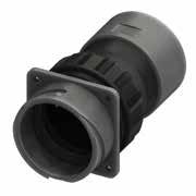
* For installation with backshell mounted, consult our sales office.
Dimension “L” can be different from the value indicated according to backshells accessories, wires size and some special insert configurations.
276 Go online
data sheets
Visit www.radiall.com/vansystem and enter the part number. CVBSG SHELL
for
& assembly instructions.
Dimensions in mm R ØC ØT1
*
Shell size ØD +0 -0.15 L max M ±0.2 K ±0.2 ØB ±0.3 Z min N Backshell Metric Thread R ±0.1 S ±0.3 ØT ±0.2 ØT2 ØT1 ØC* ±0.2 18 30.8 99 19 4 37 12 M20 27 34.9 6.5 3.1 3.4 26.5 20 34.2 116 19 4 42 15 M25 29.4 38.1 6.5 3.1 3.4 30 22 37.4 116 19.7 4 45 15 M25 31.8 41 6.5 3.1 3.4 33 24 40.9 136 20.6 4 47.8 16 M32 34.9 44.5 7.5 3.7 3.9 36 28 46.7 136 20.6 4 54.6 16 M32 39.7 50.8 7.5 3.7 3.9 42 32 53.4 140 22.2 4 61.8 16 M32 44.5 57 8 4.4 4.5 48.5 36 59.6 148 22.2 4 65.6 16 M32 49.2 63.5 8.5 4.4 4.5 55 40 65.5 151 22.2 4 74 16 M32 55.6 69.8 8.5 4.4 4.5 61 L ØB N Z T S R K M D T 0.1 T2 90° T T1 T
Panel cut out
CVBSG - Bayonet Connector with external insulated coating
Shell Material
Backshell internal thread
Series Code Shell Type Connector Class Shell finish
Gasket
Grommet (RA Class only)
Grommet cone (RA Class only)
Insulated Adapter Gasket
The accessories for this class are not always available in stock for all sizes; we suggest you consult our Sales Office for availability
RF Insulating material RF Fire resistant rubber
CVBSG Series Code CVBSG Bayonet Connector with external insulated coating
Shell Material - Aluminum
00 Shell Type 00 Front mounting Receptacle
DA Connector Class DA with waterproof O-ring (IP67***) RA with waterproof O-ring and grommet (IP67***)
T Connector Modification** T With plastic capsReceptacle connector with through holes
20-4 Insert Arrangement Size - Type
S Contact Gender S Socket contacts P Pin contacts
X Polarization Code**
M12 Backshell internal thread M
Alternate Positions
Provided with an internal Metric thread
PG Provided with an internal PG thread
CR Contact Termination - Solder contacts
CR Crimp contacts
LC Less contacts
CD5 Contact Plating - Silver plating
F7 Shell finish
CD5 Gold plating
F7 Black epoxy varnish (*)
F16 CCF - Black passivation (*) - conductive
F26 hard anodization (*)
G Panel Gasket - Without gasket
G With waterproof panel gasket
G2 With shielded panel gasket
G3 With waterproof shielded panel gasket
N Modification Code** N
Consult our sales office S
RoHS compliance (**) If required *** Protection degree: IP 67 (only in the mating area with mated connectors) according to EN 60529
P/N Sample:
277 Go online for data sheets &
Visit www.radiall.com/vansystem and enter the part number. CVBSG SHELL ØG1 N Z
assembly instructions.
RF CVBSG 00 DA 20-4 S X CR CD5 F7 G N T
M12
RF CVBSG 00DAT 20-4SX M12 CR CD5 F7 G N
(*)
Backshell
CVBSG - Bayonet Connector with external insulated coating Rear Mounting Receptacle (030) with Backshell Class (DA...M - RA...M)
Connector with backshell provided with an internal Metric or PG thread suitable for Cable Glands or conduit adapters.
* For installation with backshell mounted, consult our sales office.
Dimension “L” can be
from the value indicated according to backshells accessories, wires size and some special insert configurations.
278 Go
Visit www.radiall.com/vansystem and enter the part number. CVBSG SHELL
online for data sheets & assembly instructions.
Dimensions in mm R ØC ØT1
*
Shell size ØD +0 -0.15 L max M ±0.2 K ±0.2 ØB ±0.3 Z min N Backshell Metric Thread R ±0.1 S ±0.3 ØT ØT1 P Panel Thickness Max ØC* ±0.2 18 30.8 103 23.4 4 37 12 M20 27 34.9 M4 4.5 7.25 31.7 20 34.2 120 23.4 4 42 15 M25 29.4 38.1 M4 4.5 7.3 35 22 37.4 120 23.4 4 45 15 M25 31.8 41 M4 4.5 7.3 38.3 24 40.9 139 23.4 4 47.8 16 M32 34.9 44.5 M4 4.5 6.85 41.8 28 46.7 140 24.4 4 54.6 16 M32 39.7 50.8 M5 5.5 7.8 47.6 32 53.4 143 24.4 4 61.8 16 M32 44.5 57 M5 5.5 7.5 54.3 36 59.6 151 24.4 4 65.6 16 M32 49.2 63.5 M5 5.5 7.5 60.5 40 65.5 154 24.4 4 74 16 M32 55.6 69.8 M5 5.5 7.5 66.4 L N Z T S R K M D P ØB
different
Panel cut out
CVBSG - Bayonet Connector with external insulated coating
Series Code Shell Type Connector Class Shell finish
Grommet cone (RA Class only)
Backshell internal thread Backshell
Grommet (RA Class only) Gasket Insulated Adapter Gasket
The accessories for this class are not always available in stock for all sizes; we suggest you consult our Sales Office for availability RF Insulating material
DA Connector Class DA with waterproof O-ring (IP67***) RA with waterproof O-ring and grommet (IP67***)
T Connector Modification** T With plastic capsReceptacle connector with threaded holes FP Receptacle connector with through holes
20-4 Insert Arrangement Size - Type S Contact Gender S Socket contacts P Pin contacts X Polarization Code**
M12 Backshell internal thread M
Alternate Positions
Provided with an internal Metric thread PG
Provided with an internal PG thread
CR Contact Termination - Solder contacts
CR Crimp contacts
LC Less contacts
CD5 Contact Plating - Silver plating
F7 Shell finish
G Panel Gasket
CD5 Gold plating
F7 Black epoxy varnish (*)
F16
CCF - Black passivation (*) - conductive
F26 hard anodization (*)
- Without gasket
G With waterproof panel gasket
G2 With shielded panel gasket
G3 With waterproof shielded panel gasket N Modification Code** N
Protection degree: IP 67 (only in the mating area with mated connectors) according to EN
Consult our sales office S
279 Go online for data sheets & assembly instructions. Visit www.radiall.com/vansystem and enter the part number. CVBSG SHELL ØG1 N Z
CR CD5 F7 G N RF CVBSG 030 DA 20-4 S X CR CD5 F7 G N T
(*)
***
M12
P/N Sample: RF CVBSG 030DAT 20-4SX M12
Shell Material
RoHS compliance (**) If required
60529
RF
Fire resistant rubber
CVBSG Series Code CVBSG Bayonet Connector with external insulated coating Shell Material - Aluminum
030 Shell Type 030 Rear mounting Receptacle
CVBSG - Bayonet Connector with external insulated coating Rear Mounting Receptacle (030) with Backshell Class (DA...FS - RA...FS)
Connector with special adapter for rubber conduits.
Conduit’s size must be specified adding the diameter dimensions in the P/N (i.e.: CVBSG 030DA…FS5040…).
Rubber covered coupling nut able to protect against dust and impact.
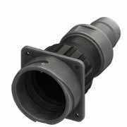
Panel cut out
* For installation with backshell mounted, consult our sales office.
Dimension “L” can be different from the value indicated according to backshells accessories, wires size and some special insert configurations.
& assembly instructions.
280 Go online
data sheets
Visit www.radiall.com/vansystem and enter the part number. CVBSG SHELL
for
Dimensions in mm R ØC ØT1
*
Shell size ØD +0 -0.15 L max M ±0.2 K ±0.2 ØB ±0.3 R ±0.1 S ±0.3 ØT ØT1 P Panel Thickness Max ØC* ±0.2 18 30.8 119 23.4 4 37 27 34.9 M4 4.5 7.25 31.7 20 34.2 132 23.4 4 42 29.4 38.1 M4 4.5 7.3 35 22 37.4 132 23.4 4 45 31.8 41 M4 4.5 7.3 38.3 24 40.9 150 23.4 4 47.8 34.9 44.5 M4 4.5 6.85 41.8 28 46.7 150 24.4 4 54.6 39.7 50.8 M5 5.5 7.8 47.6 32 53.4 150 24.4 4 61.8 44.5 57 M5 5.5 7.5 54.3 36 59.6 160 24.4 4 65.6 49.2 63.5 M5 5.5 7.5 60.5 40 65.5 165 24.4 4 74 55.6 69.8 M5 5.5 7.5 66.4 L T S R K M D P Ø 1 A Ø 2 A ØB
Backshell Conduit Size ØA1 ØA2 FS1813 18 13 FS2015 20 15 FS2520 25 20 FS2722 27 22 FS3328 33 28 FS2924 29 24 FS3530 35 30 FS3833 38 33 FS4030 40 30 FS4035 40 35 FS4540 45 40 FS5040 50 40 FS5045 50 45 FS5247 52 47 FS5550 55 50 Rubber Conduit not included
CVBSG - Bayonet Connector with external insulated coating
Backshell Conduits size
Series Code Shell Type Connector Class Shell finish
Grommet cone (RA..FS Class only) Grommet (RA..FS Class only)
The accessories for this class are not always available in stock for all sizes; we suggest you consult our Sales Office for availability xxxx
RF Insulating material RF Fire resistant rubber
CVBSG Series Code CVBSG Bayonet Connector with external insulated coating Shell Material - Aluminum
030 Shell Type 030 Rear mounting Receptacle
DA Connector Class
T Connector Modification**
DA with waterproof O-ring (IP67***)
RA with waterproof O-ring and grommet (IP67***)
T With plastic caps
Receptacle connector with threaded holes
FP Receptacle connector with through holes
20-4 Insert Arrangement Size - Type
S Contact Gender S Socket contacts P Pin contacts
X Polarization Code**
FS.. Backshell Conduits size FS
CR Contact Termination
CD5 Contact Plating
F7 Shell finish
G Panel Gasket
N Modification Code**
Alternate Positions
Provided with a special adapter for rubber conduits xxxx Conduit Size xxxx ØA1ØA2
- Solder contacts
CR Crimp contacts
LC Less contacts
- Silver plating
CD5 Gold plating
F7 Black epoxy varnish (*)
F16
CCF - Black passivation (*) - conductive
F26 hard anodization (*)
- Without gasket
G With waterproof panel gasket
G2 With shielded panel gasket
(*) RoHS compliance (**) If required *** Protection degree: IP 67 (only in the mating area with mated connectors) according to EN 60529 FS..
P/N Sample: RF CVBSG 030DAT 20-4SX FS5040 CR
G3 With waterproof shielded panel gasket
N Consult our sales office S
281 Go online for data sheets
Visit www.radiall.com/vansystem and enter the part number. CVBSG SHELL
& assembly instructions.
RF CVBSG 030 DA 20-4 S X CR CD5 F7 G N T
CD5 F7 G N
Gasket Insulated Adapter Gasket
Backshell
CVBSG - Bayonet Connector with external insulated coating Rear Mounting Receptacle (030) with Backshell Class
(DA...MTG - RA...MTG)
Connector with a special adapter for clamping and retaining rubber conduits, with nut. Conduit’s size must be specified adding the diameter dimensions in the P/N (i.e.: CVBSG 030DA…MTG2015…). Rubber covered coupling nut able to protect against dust and impact.
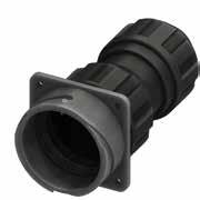
Dimensions in
Panel cut out
* For installation with backshell mounted, consult our sales office.
Rubber Conduits not included
** Dimensions ØF1 and ØF2 are determined by conduit size.
*Please consult our Sales Office for further details.
Dimension “L” can be different from the value indicated according to backshells accessories, wires size and some special insert configurations.
282 Go online
data sheets
Visit www.radiall.com/vansystem
enter the part number. CVBSG SHELL
for
& assembly instructions.
and
mm R ØC ØT1
*
Shell size ØD +0 -0.15 L max M ±0.2 K ±0.2 ØB ±0.3 ØF ØF1 Backshell Conduit Size** R ±0.1 S ±0.3 ØT ØT1 P Panel Thickness Max ØC* ±0.2 18 30.8 106 23.4 4 37 17 12 MTG1712 27 34.9 M4 4.5 7.25 31.7 20 15 MTG2015 20 34.2 124 23.4 4 42 * * * 29.4 38.1 M4 4.5 7.3 35 22 37.4 124 23.4 4 45 32 27 MTG3227 31.8 41 M4 4.5 7.3 38.3 24 40.9 145 23.4 4 47.8 * * * 34.9 44.5 M4 4.5 6.85 41.8 28 46.7 145 24.4 4 54.6 29 24 MTG2924 39.7 50.8 M5 5.5 7.8 47.6 32 53.4 147 24.4 4 61.8 * * * 44.5 57 M5 5.5 7.5 54.3 36 59.6 155 24.4 4 65.6 * * * 49.2 63.5 M5 5.5 7.5 60.5 40 65.5 160 24.4 4 74 * * * 55.6 69.8 M5 5.5 7.5 66.4 L T S R K M D P ØB ØF ØF1
CVBSG - Bayonet Connector with external insulated coating
Backshell Conduits size
Series Code Shell Type Connector Class Shell finish
Gasket
Grommet (RA..MTG Class only)
Grommet cone (RA..MTG Class only)
The accessories for this class are not always available in stock for all sizes; we suggest you consult our Sales Office for availability 2015
with
030 Shell Type 030 Rear mounting Receptacle
DA Connector Class
T Connector Modification**
DA with waterproof O-ring (IP67***)
RA with waterproof O-ring and grommet (IP67***)
T With plastic caps
Receptacle connector with threaded holes
FP Receptacle connector with through holes
20-4 Insert Arrangement Size - Type
S Contact Gender S Socket contacts P Pin contacts
P/N Sample: RF CVBSG 030DAT 20-4SX MTG2015
Polarization Code** Alternate Positions
MTG Backshell Conduits size MTG
Provided with a special adapter for rubber conduits, with nut. 2015 Conduit Size xxxx ØFØF1
- Solder contacts
CR Contact Termination
CD5 Contact Plating
F7 Shell finish
CR Crimp contacts
LC Less contacts
- Silver plating
CD5 Gold plating
G Panel Gasket
F7 Black epoxy varnish (*)
F16
CCF - Black passivation (*) - conductive
F26 hard anodization (*)
- Without gasket
G With waterproof panel gasket
G2 With shielded panel gasket
RoHS compliance (**) If required *** Protection degree: IP 67 (only in the mating area with mated connectors) according to EN 60529 MTG
G3 With waterproof shielded panel gasket N Modification Code** N
Consult our sales office S
283 Go online for data sheets
Visit www.radiall.com/vansystem and enter the part number. CVBSG SHELL
& assembly instructions.
CR
RF CVBSG 030 DA 20-4 S X CR CD5 F7 G N T
CD5 F7 G N
(*)
H
Gasket
RF Fire
Retention System
Clamping Nut Backshell RF Insulating material
resistant rubber CVBSG Series Code CVBSG Bayonet Connector
external insulated coating Shell Material - Aluminum
X
CVBSG - Bayonet Connector with external insulated coating
Plug Connector (06) with Backshell Class (DAM - RAM)
Protected connector with rubber coated backshell and strain relief.
Cable retention and watertightness are guaranteed by conical gasket and metal cone.
Rubber covered coupling nut able to protect against dust and impact.
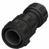
284 Go online for data sheets & assembly instructions. Visit www.radiall.com/vansystem and enter the part number. CVBSG SHELL Shell size ØG1 ØG2 L max ØF Min Max 18 49 43.5 102 9.6 15.9 20 51.5 46 120 11.3 19 22 56 50.5 120 11.3 19 24 60 54 145 15.5 23.8 28 67 61 145 15.5 23.8 32 76 69 147 23.4 31.8 36 82 73.5 155 25.4 35 40 88 80 160 30 41.3
Dimension “L” can be different from the value indicated according to backshells accessories, wires size and some special insert configurations. Dimensions in mm ØG1 ØG2 ØF L
CVBSG - Bayonet Connector with external insulated coating
Grommet cone (RAM Class only) Grommet (RAM Class only)
The accessories for this class are not always available in stock for all sizes; we suggest you consult our Sales Office for availability
CVBSG Series Code CVBSG Bayonet Connector with external insulated coating Shell Material - Aluminum 06 Shell Type 06 Plug Connector
DAM Connector Class DAM with waterproof O-ring (IP67***)
with waterproof O-ring and grommet (IP67***)
T Connector Modification** T With plastic caps
20-4 Insert Arrangement Size - Type S Contact Gender S Socket contacts P Pin contacts X Polarization Code** Alternate Positions CR Contact Termination - Solder contacts CR Crimp contacts
LC Less contacts
P/N Sample: RF CVBSG 06DAMT 20-4SX CR CD5 F7 N
CD5 Contact Plating - Silver plating
F7 Shell finish
CD5 Gold plating
F7 Black epoxy varnish (*)
F16
CCF - Black passivation (*) - conductive
F26 hard anodization (*) N Modification Code**
285 Go online for data sheets
Visit www.radiall.com/vansystem and enter the part number.
SHELL
& assembly instructions.
CVBSG
(*)
***
60529
RoHS compliance (**) If required
Protection degree: IP 67 (only in the mating area with mated connectors) according to EN
Class Shell finish RF CVBSG 06 DAM 20-4 S X CR CD5 F7 N T Shell Material
Gasket Strain
Series Code Shell Type Connector
Relief Backshell RF Insulating material RF Fire resistant rubber
RAM
S
N Consult our sales office
CVBSG - Bayonet Connector with external insulated coating
Plug Connector (06) with Backshell Class (DA..M - RA..M)
Connector with backshell provided with an internal Metric or PG thread suitable for Cable Glands or conduit adapters. Rubber covered coupling nut able to protect against dust and impact.
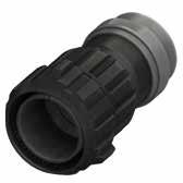
286 Go online for data sheets & assembly instructions. Visit www.radiall.com/vansystem and enter the part number. CVBSG SHELL L ØG1 ØG2 N Z ØB
Dimension “L” can be different from the value indicated according to backshells accessories, wires size and some special insert configurations. Dimensions in mm Shell size ØG1 ØG2 L max ØB ±0.3 Z min N Backshell Metric Thread 18 49 43.5 99 37 12 M20 20 51.5 46 116 42 15 M25 22 56 50.5 116 45 15 M25 24 60 54 141 47.8 16 M32 28 67 61 141 54.6 16 M32 32 76 69 143 61.8 16 M32 36 82 73.5 151 65.6 16 M32 40 88 80 156 74 16 M32
CVBSG - Bayonet Connector with external insulated coating
Grommet cone (RA..M RA..PG Class only) Grommet (RA..M
Connector
with waterproof O-ring and grommet (IP67***) T Connector Modification** T With plastic caps 20-4 Insert Arrangement
- Type
Protection degree: IP 67 (only in the mating area with mated connectors) according to EN 60529 The accessories for this class are not always available in stock for all sizes;
Contact Gender
Socket contacts
Pin contacts
Polarization Code** Alternate Positions
with an internal Metric thread
with an internal PG thread
Solder contacts
Crimp contacts
Less contacts CD5 Contact Plating
Modification Code**
Silver plating
Gold plating
Black epoxy varnish (*)
- Black passivation (*) - conductive
hard anodization (*)
Consult our sales office
287 Go online for data sheets & assembly instructions. Visit www.radiall.com/vansystem and enter the part number. CVBSG SHELL ØG1 N Z
RF CVBSG 06DAT 20-4SX M12 CR CD5 F7 N Series Code Shell Type Connector Class Shell finish RF CVBSG 06 DA 20-4 S X CR CD5 F7 N T
Gasket M12
(*)
***
Gasket RF Insulating material RF Fire resistant rubber CVBSG Series Code CVBSG Bayonet
with external insulated coating Shell Material - Aluminum 06 Shell Type 06 Plug Connector DA
DA
RA
X
M12
M
PG
-
CR
F7
F7
F16
N
N
S
P/N Sample:
Backshell
RA..PG Class only)
Backshell internal thread
RoHS compliance (**) If required
we suggest you consult our Sales Office for availability Insulated Adapter
Connector
Class
with waterproof O-ring (IP67***)
Size
S
S
P
Backshell internal thread
Provided
Provided
CR Contact Termination
LC
-
CD5
Shell finish
CCF
F26
CVBSG - Bayonet Connector with external insulated coating
Plug Connector (06) with Backshell Class (DA..FS - RA..FS)
Connector with special adapter for rubber conduits.
Conduit’s size must be specified adding the diameter dimensions in the P/N (i.e.: CVBSG 06DA…FS5040…).
Rubber covered coupling nut able to protect against dust and impact.
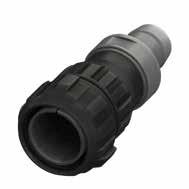
Please consult our Sales Office for further details about this dimension and according to conduit size.
“L” can be different from the value indicated according to backshells accessories, wires size and some special insert configurations.
288 Go online for data sheets &
Visit www.radiall.com/vansystem and enter the part number. CVBSG SHELL
assembly instructions.
L ØG1 ØG2 Ø 1 A Ø 2 A Shell size ØG1 ØG2 L max ØB ±0.3 18 49 43.5 115 37 20 51.5 46 128 42 22 56 50.5 128 45 24 60 54 150 47.8 28 67 61 150 54.6 32 76 69 150 61.8 36 82 73.5 160 65.6 40 88 80 165 74 Dimension
Dimensions in mm
Rubber Conduit not included Backshell Conduit Size ØA1 ØA2 FS1813 18 13 FS2015 20 15 FS2520 25 20 FS2722 27 22 FS3328 33 28 FS2924 29 24 FS3530 35 30 FS3833 38 33 FS4030 40 30 FS4035 40 35 FS4540 45 40 FS5040 50 40 FS5045 50 45 FS5247 52 47 FS5550 55 50
CVBSG - Bayonet Connector with external insulated coating
The accessories for this class are not always available in stock for all sizes; we suggest you consult our Sales Office for availability
(IP67***)
Contact Gender S Socket contacts P Pin contacts
Provided with a special adapter for rubber conduits
Solder contacts
Contact Termination
Crimp contacts LC Less contacts CD5 Contact Plating
Silver plating CD5 Gold plating
F7 Black epoxy varnish (*) F16 CCF - Black passivation (*) - conductive F26 hard anodization (*)
office
289 Go online for data sheets & assembly instructions. Visit www.radiall.com/vansystem and enter the part number.
SHELL
CVBSG
06DAT
FS5040 CR CD5 F7 N Series
Type
Class Shell finish RF CVBSG 06 DA 20-4 S X CR CD5 F7 N T Shell Material FS.. (*) RoHS compliance (**) If required *** Protection degree:
67
in the mating area
mated connectors) according to EN 60529 Backshell Grommet
Grommet
Gasket Insulated Adapter Gasket
xxxx RF Insulating material RF Fire resistant rubber
Series Code CVBSG Bayonet Connector
external insulated coating Shell Material - Aluminum 06 Shell Type 06 Plug Connector
DA
RA
X
Alternate
FS
xxxx Conduit Size xxxx ØA1ØA2 CR
CR
F7 Shell finish
P/N Sample: RF CVBSG
20-4SX
Code Shell
Connector
IP
(only
with
cone (RA..FS Class only)
(RA..FS Class only)
Backshell Conduits size
CVBSG
with
DA Connector Class
with waterproof O-ring (IP67***)
with waterproof O-ring and grommet
# T Connector Modification** T With plastic caps 20-4 Insert Arrangement Size - Type S
Polarization Code**
Positions FS.. Backshell Conduits size
-
-
N
Modification Code** N Consult our sales
S
CVBSG - Bayonet Connector with external insulated coating
Plug Connector (06) with Backshell Class (DA..MTG - RA..MTG)
Connector with a special adapter for clamping and retaining rubber conduits, with nut. Conduit’s size must be specified adding the diameter dimensions in the P/N (i.e.: CVBSG 06DA…MTG2025…).
Rubber covered coupling nut able to protect against dust and impact.
Rubber Conduits not included
** Dimensions ØF1 and ØF2 are determined by conduit size.
*Please consult our Sales Office for further details.
Dimensions in mm
Dimension “L” can be different from the value indicated according to backshells accessories, wires size and some special insert configurations.
290 Go online for data sheets & assembly instructions. Visit www.radiall.com/vansystem and enter the part number. CVBSG SHELL Shell size ØG1 ØG2 L max ØF ØF1 Backshell Conduit Size** 18 49 43.5 102 17 12 MTG1712 20 15 MTG2015 20 51.5 46 120 * * * 22 56 50.5 120 32 27 MTG3227 24 60 54 145 * * * 28 67 61 145 29 24 MTG2924 32 76 69 147 * * * 36 82 73.5 155 * * * 40 88 80 160 * * *
ØG1 ØG2 ØF ØF1 L
CVBSG - Bayonet Connector with external insulated coating
Contact Gender
Grommet (RA..MTG Class only)
Grommet cone (RA..MTG Class only)
Polarization Code** Alternate Positions MTG Backshell Conduits size MTG Provided with a special adapter for rubber conduits, with nut.
Conduit Size
CR Contact Termination
Solder contacts
Crimp contacts
Less contacts
CD5 Contact Plating - Silver plating
CD5 Gold plating
Shell finish F7 Black epoxy varnish (*) F16 CCF - Black passivation (*) - conductive
F26 hard anodization (*)
Consult our sales office
291 Go online for data sheets & assembly instructions. Visit www.radiall.com/vansystem and enter the part number.
SHELL
CVBSG
CR CD5
N (*) RoHS compliance
required ***
67
mating
mated connectors)
to EN 60529
P/N Sample: RF CVBSG 06DAT 20-4SX MTG2015
F7
(**) If
Protection degree: IP
(only in the
area with
according
Series Code Shell Type Connector Class Shell finish RF CVBSG 06 DA 20-4 S X CR CD5 F7 N T Shell Material MTG
2015
H
The accessories for this class are not always available in stock for all sizes; we suggest you consult our Sales Office for availability
Backshell Conduits size
Conduit Size
Gasket
Gasket
Backshell
RF Fire resistant rubber
Series Code CVBSG
Shell Material - Aluminum 06 Shell Type 06 Plug Connector
DA
RA
X
2015
CR
Retention System
Clamping Nut
RF Insulating material
CVBSG
Bayonet Connector with external insulated coating
DA Connector Class
with waterproof O-ring (IP67***)
with waterproof O-ring and grommet (IP67***) # T Connector Modification** T With plastic caps 20-4 Insert Arrangement Size - Type S
S Socket contacts P Pin contacts
xxxx ØFØF1
-
LC
F7
N
S
N Modification Code**
CVBSG - Bayonet Connector with external insulated coating
Plug Connector (06) with Backshell Class (AMK - MK)
Connectors provided with gasket and iris spring connected to one another by an internal ring. The iris spring is used to connect multicore jacketed cables or jacketed hoses. An additional gasket added outside of the central body guarantees the complete watertightness. Clamping range on the dimension table has to be chosen according to the cable size and its shielding. Rubber covered coupling nut able to protect against dust and impact.
Dimension “L” can be different from the value indicated according to backshells accessories, wires size and some special insert configurations.
** Clamping range to be verified with cable section. Please consult our Sales Office.
292 Go online for data sheets & assembly instructions. Visit www.radiall.com/vansystem and enter the part number. CVBSG SHELL
Shell size ØG1 ØG2 L ØF Clamping Range ** Min Max 18 49 43.5 102 13 16 20 51.5 46 120 16 19 22 56 50.5 120 16 19 24 60 54 145 19 22 28 67 61 145 22 25 32 76 69 147 28 31 36 82 73.5 155 32 35 40 88 80 160 38 41
Dimensions in mm
ØG1 ØG2 ØF L
CVBSG - Bayonet Connector with external insulated coating
The accessories for this class are not always available in stock for all sizes; we suggest you consult our Sales Office for availability
Contact Gender S Socket contacts P Pin contacts
Polarization Code** Alternate Positions CR Contact Termination - Solder contacts CR Crimp contacts LC Less contacts
With waterproof O-ring and grommet (IP67***)#
Connector Modification** T With plastic caps
Insert Arrangement Size - Type
CD5 Contact Plating - Silver plating
CD5 Gold plating
F7 Black epoxy varnish (*) F16 CCF - Black passivation (*) - conductive F26 hard anodization (*)
293 Go online for data sheets & assembly instructions. Visit www.radiall.com/vansystem and enter the part number.
SHELL Series
Type
Shell finish
CVBSG
Code Shell
Connector Class
Backshell Grommet cone (MK Class only) Grommet (MK Class only) Gasket P/N Sample: RF CVBSG 06MKT 20-4SX CR CD5 F7 N RF CVBSG 06 MK 20-4 S X CR CD5 F7 N T (*)
***
Gasket Internal Ring Iris Spring Clamping Nut Gasket
Shell
- Aluminum 06 Shell Type 06
Connector
AMK
MK
RoHS compliance (**) If required
Protection degree: IP 67 (only in the mating area with mated connectors) according to EN 60529
RF Insulating material RF Fire resistant rubber CVBSG Series Code CVBSG Bayonet Connector with external insulated coating
Material
Plug
MK Connector Class
with waterproof O-ring (IP67***)
T
20-4
S
X
F7
finish
N
N
S
Shell
Modification Code**
Consult our sales office
CVBSG - Bayonet Connector with external insulated coating
Plug Connector (96) with Backshell Class (AMK - MK)
Connector provided with grounding finger to guarantee shielding; Connectors provided with gasket and iris spring connected to one another by an internal ring. The iris spring is used to connect multicore jacketed cables or jacketed hoses. An additional gasket added outside of the central body guarantees the complete watertightness. Clamping range on the dimension table has to be chosen according to the cable size and its shielding. Rubber covered coupling nut able to protect against dust and impact.
Grounding finger
Dimensions in mm
Dimension “L” can be different from the value indicated according to backshells accessories, wires size and some special insert configurations.
** Clamping range to be verified with cable section. Please consult our Sales Office.
294 Go online for data sheets & assembly instructions. Visit www.radiall.com/vansystem and enter the part number. CVBSG SHELL
ØG1 ØG2 ØF L Shell size ØG1 ØG2 L ØF Clamping Range ** Min Max 18 49 43.5 102 13 16 20 51.5 46 120 16 19 22 56 50.5 120 16 19 24 60 54 145 19 22 28 67 61 145 22 25 32 76 69 147 28 31 36 82 73.5 155 32 35 40 88 80 160 38 41
Connector with
contacts
Polarization Code** Alternate Positions CR Contact Termination - Solder contacts CR Crimp contacts LC Less contacts
CD5 Contact Plating - Silver plating CD5 Gold plating
passivation (*) - conductive
295 Go online for data sheets & assembly instructions. Visit www.radiall.com/vansystem and enter the part number.
SHELL Series
Shell finish
CVBSG
Code Shell Type Connector Class
Backshell Grommet cone (MK Class only) Grommet (MK Class
Gasket P/N Sample: RF CVBSG 96MKT 20-4SX CR CD5 F7 N RF CVBSG 96 MK 20-4 S X CR CD5 F7 N T (*)
***
Gasket Internal Ring Iris Spring Clamping Nut Gasket RF
RF Fire resistant rubber
Series Code CVBSG
Shell
-
96
06
AMK
MK
S
X
CVBSG - Bayonet
external insulated coating The accessories for this class are not always available in stock for all sizes; we suggest you consult our Sales Office for availability
only)
RoHS compliance (**) If required
Protection degree: IP 67 (only in the mating area with mated connectors) according to EN 60529
Insulating material
CVBSG
Bayonet Connector with external insulated coating
Material
Aluminum
Shell Type
Plug Connector with grounding finger MK Connector Class
with waterproof O-ring (IP67***)
With waterproof O-ring and grommet (IP67***)# T Connector Modification** T With plastic caps 20-4 Insert Arrangement Size - Type
Contact Gender S Socket contacts P Pin
F7 Shell finish
N
N
S
F7 Black epoxy varnish (*) F16 CCF - Black
F26 hard anodization (*)
Modification Code**
Consult our sales office
CVBSG - Bayonet Connector with external insulated coating
Plug Connector (08) with 90° Elbow Class (DAM - RAM)
Protected connector with rubber coated backshell and strain relief.
Cable retention and watertightness are guaranteed by conical gasket and metal cone.
Rubber covered coupling nut able to protect against dust and impact.
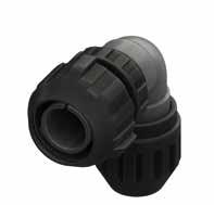
Dimension “L” can be different from the value indicated according to backshells accessories, wires size and some special insert configurations. Dimensions
296 Go online for data sheets & assembly instructions. Visit www.radiall.com/vansystem and enter the part number. CVBSG SHELL Shell size ØG1 ØG2 L max H1 max H2 max ØF Min Max 18 49 43.5 68 66 90.5 9.6 15.9 20 51.5 46 71 68 93.8 11.3 19 22 56 50.5 71 76 104 11.3 19 24 60 54 76 83 113 15.5 23.8 28 67 61 76 84 117.5 15.5 23.8 32 76 69 80 88 126 23.4 31.8 36 82 73.5 84 96 137 25.4 35 40 88 80 88 98 142 30 41.3 ØG1 ØG2 H2 H1 L ØF
in mm
CVBSG - Bayonet Connector with external insulated coating
Grommet cone (RAM Class only)
Grommet (RAM Class only) Gasket
RF Insulating material RF Fire resistant rubber
CVBSG Series Code CVBSG Bayonet Connector with external insulated coating Shell Material - Aluminum 08 Shell Type 08 Plug Connector with 90° elbow
DAM Connector Class DAM with waterproof O-ring (IP67***) RAM with waterproof O-ring and grommet (IP67***) # T Connector Modification** T With plastic caps
20-4 Insert Arrangement Size - Type S Contact Gender S Socket contacts P Pin contacts X Polarization Code** Alternate Positions CR Contact Termination - Solder contacts CR Crimp contacts
LC Less contacts
CD5 Contact Plating - Silver plating
CD5 Gold plating F7 Shell finish
F7 Black epoxy varnish (*)
F16
Consult our sales office
CCF - Black passivation (*) - conductive N Modification Code**
RoHS compliance (**) If required *** Protection degree: IP 67 (only in the mating area with mated connectors) according to EN 60529
P/N Sample: RF CVBSG 08DAMT 20-4SX CR CD5 F7 N
The accessories for this class are not always available in stock for all sizes; we suggest you consult our Sales Office for availability (#) In some sizes the grommet cone is not needed
297 Go online for data sheets
Visit www.radiall.com/vansystem and enter the part number.
SHELL
& assembly instructions.
CVBSG
(*)
Shell finish
20-4 S X CR CD5 F7 N
Series Code Shell Type Connector Class
RF CVBSG 08 DAM
T
Strain
90°
Relief
Elbow
N
S
CVBSG - Bayonet Connector with external insulated coating
Plug Connector (08) with 90° Elbow Class (DA..M - RA..M)
Connector with backshell provided with an internal Metric or PG thread suitable for Cable Glands or conduit adapters. Rubber covered coupling nut able to protect against dust and impact.
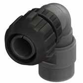
Dimension “L” can be different from the value indicated according to backshells accessories, wires size and some special insert configurations.
298 Go online for data sheets & assembly
Visit www.radiall.com/vansystem and enter the part number. CVBSG SHELL
instructions.
Dimensions in mm Shell size ØG1 ØG2 L max H1 H2 Z min N Backshell Metric Thread 18 49 43.5 68 65 89.5 12 M20 20 51.5 46 71 67 92.8 15 M25 22 56 50.5 71 73 101 15 M25 24 60 54 76 80 110 16 M32 28 67 61 76 82 115.5 16 M32 32 76 69 80 84 122 16 M32 36 82 73.5 84 92 133 16 M32 40 88 80 88 94 138 16 M32 ØG1 ØG2 H2 H1 L N Z
CVBSG - Bayonet Connector with external insulated coating
Grommet cone (RA..M
Class only) # Grommet (RA..M
Connector Class
Connector with external
with waterproof O-ring (IP67***)
with waterproof O-ring and grommet (IP67***) #
Connector Modification** T With plastic caps 20-4 Insert Arrangement Size - Type
The accessories for this class are not always available in stock for all sizes; we suggest you consult our Sales Office for availability (#) In some sizes the grommet cone is not needed
Contact Gender S Socket contacts
Pin contacts
Polarization Code** Alternate Positions
Backshell internal thread
Contact Termination
Provided with an internal Metric thread
Provided with an internal PG thread
Solder contacts
Crimp contacts
Less contacts
CD5 Contact Plating - Silver plating CD5 Gold plating F7 Shell finish F7 Black epoxy varnish (*) F16 CCF - Black passivation (*) - conductive N Modification Code**
Consult our sales office
299 Go online for data sheets & assembly instructions. Visit www.radiall.com/vansystem and enter the part number.
SHELL
CVBSG
RF CVBSG 08DAT
M12 CR CD5 F7 N Series
Type
Shell finish RF CVBSG 08 DA 20-4 S X CR CD5 F7 N T M12 Backshell
(*)
***
60529
P/N Sample:
20-4SX
Code Shell
Connector Class
internal thread
RoHS compliance (**) If required
Protection degree: IP 67 (only in the mating area with mated connectors) according to EN
90°
Elbow
Gasket Insulated Adapter Gasket RF Insulating material RF Fire resistant rubber
Series Code CVBSG Bayonet
insulated
Shell Material - Aluminum 08
Type 08 Plug
DA
RA
S
X
M12
M
PG
CR
RA..PG
RA..PG Class only)
CVBSG
coating
Shell
Connector with 90° elbow DA
T
P
CR
-
LC
N
S
CVBSG - Bayonet Connector with external insulated coating Plug Connector (08) with 90° Elbow Class (DA..FS - RA..FS)
Connector with special adapter for rubber conduits. Conduit’s size must be specified adding the diameter dimensions in the P/N (i.e.: CVBSG 08DA…FS5040…). Rubber covered coupling nut able to protect against dust and impact.
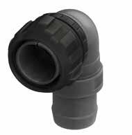
Dimension “L” can be different from the value indicated according to backshells accessories, wires size and some special insert configurations.
300 Go online for data sheets
assembly
Visit www.radiall.com/vansystem and enter the part number. CVBSG SHELL
&
instructions.
Dimensions in mm ØG1 ØG2 H2 H1 L Ø A1 Ø 2 A Shell size ØG1 ØG2 L max H1 H2 18 49 43.5 68 85 109.5 20 51.5 46 71 85 110.8 22 56 50.5 71 85 113 24 60 54 76 85 115 28 67 61 76 85 118.5 32 76 69 80 85 123 36 82 73.5 84 90 131 40 88 80 88 95 139
Rubber Conduit not included Backshell Conduit Size ØA1 ØA2 FS1813 18 13 FS2015 20 15 FS2520 25 20 FS2722 27 22 FS3328 33 28 FS2924 29 24 FS3530 35 30 FS3833 38 33 FS4030 40 30 FS4035 40 35 FS4540 45 40 FS5040 50 40 FS5045 50 45 FS5247 52 47 FS5550 55 50
Please consult our Sales Office for further details about this dimension and according to conduit size.
CVBSG - Bayonet Connector with external insulated coating
with a special adapter for rubber conduits
Solder contacts
Crimp contacts
Less contacts CD5 Contact Plating
Silver plating
Gold plating
Black epoxy varnish (*)
- Black passivation (*)
conductive
301 Go online for data sheets & assembly instructions. Visit www.radiall.com/vansystem and enter the part number.
SHELL
CVBSG
RF CVBSG 08DAT 20-4SX FS5040 CR CD5 F7 N Series
Type Connector Class Shell finish RF CVBSG 08 DA 20-4 S X CR CD5 F7 N T FS
size (*) RoHS compliance (**)
required ***
IP 67 (only in the mating area
mated connectors) according to EN 60529
90°
Gasket Insulated Adapter Gasket RF Insulating material RF Fire resistant rubber CVBSG Series Code CVBSG Bayonet Connector with external insulated coating Shell Material - Aluminum 08 Shell Type 08 Plug Connector with 90° elbow DA
Class DA with
O-ring (IP67***) RA
# T
T
Size
S
S
P
X
Code** Alternate
FS..
FS Provided
xxxx
Size xxxx ØA1ØA2 CR
-
CR
LC
-
CD5
F7
F7
F16
N
N
S xxxx
P/N Sample:
Code Shell
Backshell Conduits
If
Protection degree:
with
The accessories for this class are not always available in stock for all sizes; we suggest you consult our Sales Office for availability (#) In some sizes the grommet cone is not needed
Elbow Grommet cone (RA..FS Class only) # Grommet (RA..FS Class only)
Connector
waterproof
with waterproof O-ring and grommet (IP67***)
Connector Modification**
With plastic caps 20-4 Insert Arrangement
- Type
Contact Gender
Socket contacts
Pin contacts
Polarization
Positions
Backshell Conduits size
Conduit
Contact Termination
Shell finish
CCF
-
Modification Code**
Consult our sales office
CVBSG - Bayonet Connector with external insulated coating
Plug Connector (08) with 90° Elbow Class (DA..MTG - RA..MTG)
Connector with a special adapter for clamping and retaining rubber conduits, with nut.
Conduit’s size must be specified adding the diameter dimensions in the P/N (i.e.: CVBSG 08DA…MTG2025…).
Rubber covered coupling nut able to protect against dust and impact.
** Dimensions ØF1 and ØF2 are determined by conduit size.
Dimensions in mm
Dimension “L” can be different from the value indicated according to backshells accessories, wires size and some special insert configurations.
302 Go online for data sheets & assembly instructions. Visit www.radiall.com/vansystem and enter the part number. CVBSG SHELL Shell size ØG1 ØG2 L max H1 max H2 max ØF ØF1 Backshell Conduit Size** 18 49 43.5 68 66 90.5 17 12 MTG1712 20 15 MTG2015 20 51.5 46 71 68 93.8 * * * 22 56 50.5 71 76 104 32 27 MTG3227 24 60 54 76 83 113 * * * 28 67 61 76 84 117.5 29 24 MTG2924 32 76 69 80 88 126 * * * 36 82 73.5 84 96 137 * * * 40 88 80 88 98 142 * * * ØG1 ØG2 H2 H1 L ØF ØF1 Rubber
not included
our
Conduits
*Please consult
Sales Office for further details.
CVBSG - Bayonet Connector with external insulated coating
Backshell Conduits size
Grommet cone (RA..MTG Class only) Grommet (RA..MTG Class only)
The accessories for this class are not always available in stock for all sizes; we suggest you consult our Sales Office for availability
Conduits size
Connector Class
with waterproof O-ring (IP67***)
with waterproof O-ring and grommet (IP67***) # T Connector Modification**
With plastic caps 20-4 Insert Arrangement
Provided with a special adapter for rubber conduits, with nut.
Conduit Size xxxx ØFØF1 CR Contact Termination - Solder contacts
Crimp contacts LC Less contacts
CD5 Contact Plating - Silver plating
CD5 Gold plating F7 Shell finish
F7 Black epoxy varnish (*)
F16
CCF - Black passivation (*) - conductive
office
In some sizes the grommet cone is not needed
303 Go online for data sheets & assembly
Visit www.radiall.com/vansystem and enter the part number.
SHELL
instructions.
CVBSG
CR
(*)
***
P/N Sample: RF CVBSG 08DAT 20-4SX MTG2015
CD5 F7 N
RoHS compliance (**) If required
Protection degree: IP 67 (only in the mating area with mated connectors) according to EN 60529 90° Elbow
Gasket Retention
System
Gasket
Shell
RF CVBSG 08 DA 20-4 S X CR CD5 F7 N T Shell
MTG
2015
H2 H1 ØF ØF1 RF
RF Fire resistant rubber
Series
CVBSG
08
08
DA
RA
S
P
X
(#)
Clamping Nut Series Code Shell Type Connector Class
finish
Material
Conduit Size
Insulating material
CVBSG
Code
Bayonet Connector with external insulated coating Shell Material - Aluminum
Shell Type
Plug Connector with 90° elbow DA
T
Size - Type S Contact Gender
Socket contacts
Pin contacts
Polarization Code** Alternate Positions MTG Backshell
MTG
2015
CR
S
N Modification Code** N Consult our sales
CVBSG - Bayonet Connector with external insulated coating
Plug Connector with rubber covered coupling nut (short version) (61) with Backshell Class (DAM - RAM)
Protected connector with rubber coated backshell and strain relief.
Cable retention and watertightness are guaranteed by conical gasket and metal cone.
Rubber covered coupling nut (short version) able to protect against dust and impact.
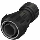
304 Go online for data sheets & assembly instructions. Visit www.radiall.com/vansystem and enter the part number. CVBSG SHELL Shell size ØG1 ØG2 L max ØF Min Max 18 49 43.5 102 9.6 15.9 20 51.5 46 120 11.3 19 22 56 50.5 120 11.3 19 24 60 54 145 15.5 23.8 28 67 61 145 15.5 23.8 32 76 69 147 23.4 31.8 36 82 73.5 155 25.4 35 40 88 80 160 30 41.3
Dimension “L” can be different from the value indicated according to backshells accessories, wires size and some special insert configurations. Dimensions in mm ØG1 ØG2 ØF L 61
CVBSG - Bayonet Connector with external insulated coating
The accessories for this class are not always available in stock for all sizes; we suggest you consult our Sales Office for availability Series Code Shell
Grommet cone (RAM Class only) Grommet (RAM Class only)
CVBSG Series Code CVBSG Bayonet Connector with external insulated coating Shell Material - Aluminum
61 Shell Type 61
Plug Connector Rubber covered coupling nut (short version)
DAM Connector Class DAM with waterproof O-ring (IP67***) RAM with waterproof O-ring and grommet (IP67***)
T Connector Modification** T With plastic caps
20-4 Insert Arrangement Size - Type S Contact Gender S Socket contacts P Pin contacts X Polarization Code** Alternate Positions
P/N Sample: RF CVBSG 61DAMT 20-4SX CR CD5 F7 N
CR Contact Termination
- Solder contacts
CR Crimp contacts
LC Less contacts
CD5 Contact Plating - Silver plating
F7 Shell finish
CD5 Gold plating
F7 Black epoxy varnish (*)
F16
CCF - Black passivation (*) - conductive
F26 hard anodization (*) N Modification Code** N
Consult our sales office S
305 Go online for data sheets
Visit www.radiall.com/vansystem and enter the part number.
SHELL
& assembly instructions.
CVBSG
(*)
60529
RoHS compliance (**) If required *** Protection degree: IP 67 (only in the mating area with mated connectors) according to EN
Shell finish RF CVBSG 61 DAM 20-4 S X CR CD5 F7 N T Shell
Type Connector Class
Material
Gasket Strain Relief Backshell RF Insulating material RF Fire resistant rubber
CVBSG - Bayonet Connector with external insulated coating
Plug Connector with rubber covered coupling nut (short version) (61) with Backshell Class (DA..M - RA..M)
Connector with backshell provided with an internal Metric or PG thread suitable for Cable Glands or conduit adapters. Rubber covered coupling nut (short version) able to protect against dust and impact.
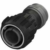
Dimension “L” can be different from the value indicated according to backshells accessories, wires size and some special insert configurations.
306 Go online for data sheets & assembly instructions. Visit www.radiall.com/vansystem and enter the part number. CVBSG SHELL L ØG1 ØG2 N Z
Dimensions in mm Shell size ØG1 ØG2 L max Z min N Backshell Metric Thread 18 49 43.5 99 12 M20 20 51.5 46 116 15 M25 22 56 50.5 116 15 M25 24 60 54 141 16 M32 28 67 61 141 16 M32 32 76 69 143 16 M32 36 82 73.5 151 16 M32 40 88 80 156 16 M32 61
CVBSG - Bayonet Connector with external insulated coating
Backshell internal thread
Grommet (RA..M RA..PG Class only) Gasket
Grommet cone (RA..M RA..PG Class only)
Backshell
The accessories for this class are not always available in stock for all sizes; we suggest you consult our Sales Office for availability
S Contact Gender S Socket contacts P Pin contacts X Polarization Code** Alternate Positions M12 Backshell internal thread
Plug Connector Rubber covered coupling nut (short version) DA Connector Class
with waterproof O-ring (IP67***)
with waterproof O-ring and grommet (IP67***) T Connector Modification** T With plastic caps
20-4 Insert Arrangement Size - Type
Provided with an internal Metric thread PG Provided with an internal PG thread
CR Contact Termination - Solder contacts CR Crimp contacts
LC Less contacts
CD5 Contact Plating - Silver plating
CD5 Gold plating F7 Shell finish
F7 Black epoxy varnish (*)
F16 CCF - Black passivation (*) - conductive
F26 hard anodization (*) N Modification Code** N
Consult our sales office
RoHS compliance (**) If required *** Protection degree: IP 67 (only in the mating area with mated connectors) according to EN 60529
P/N Sample:
307 Go online for data sheets & assembly instructions. Visit www.radiall.com/vansystem and enter the part number. CVBSG SHELL ØG1 N Z
CR
Shell finish RF CVBSG 61 DA 20-4 S X CR CD5 F7 N T
RF CVBSG 06DAT 20-4SX M12
CD5 F7 N Series Code Shell Type Connector Class
M12
(*)
RF Fire resistant rubber
Series
CVBSG
61
DA
Insulated Adapter Gasket RF Insulating material
CVBSG
Code
Bayonet Connector with external insulated coating Shell Material - Aluminum 61 Shell Type
RA
M
S
CVBSG - Bayonet Connector with external insulated coating
Plug Connector with rubber covered coupling nut (short version) (81) with 90° Elbow Class (DA..M - RA..M)
Connector with backshell provided with an internal Metric or PG thread suitable for Cable Glands or conduit adapters. Rubber covered coupling nut (short version) able to protect against dust and impact.
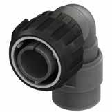
308 Go online for data sheets & assembly instructions. Visit www.radiall.com/vansystem and enter the part number. CVBSG SHELL
Dimension “L” can be different from the value indicated according to backshells accessories, wires size and some special insert configurations. Dimensions in mm Shell size ØG1 ØG2 L max H1 H2 Z min N Backshell Metric Thread 18 49 43.5 68 65 89.5 12 M20 20 51.5 46 71 67 92.8 15 M25 22 56 50.5 71 73 101 15 M25 24 60 54 76 80 110 16 M32 28 67 61 76 82 115.5 16 M32 32 76 69 80 84 122 16 M32 36 82 73.5 84 92 133 16 M32 40 88 80 88 94 138 16 M32 ØG1 ØG2 H2 H1 L N Z 81
CVBSG - Bayonet Connector with external insulated coating
Grommet cone (RA..M RA..PG Class only) #
81 Shell Type
Grommet (RA..M RA..PG Class only)
Bayonet Connector with external insulated coating
Plug Connector with 90° elbow Rubber covered coupling nut (short version)
DA Connector Class DA with waterproof O-ring (IP67***) RA with waterproof O-ring and grommet (IP67***) #
T Connector Modification** T With plastic caps
20-4 Insert Arrangement Size - Type S Contact Gender S Socket contacts P Pin contacts X Polarization Code** Alternate Positions
Backshell internal thread
P/N
The accessories for this class are not always available in stock for all sizes; we suggest you consult our Sales Office for availability (#) In some sizes the grommet cone is not needed 90° Elbow
Provided with an internal Metric thread
Provided with an internal PG thread
CR Contact Termination - Solder contacts
Crimp contacts LC Less contacts
CD5 Contact Plating - Silver plating
CD5 Gold plating F7 Shell finish F7 Black epoxy varnish (*) F16 CCF - Black passivation (*) - conductive N Modification Code**
Consult our sales office
RoHS compliance (**) If required *** Protection degree: IP 67 (only in the mating area with mated connectors) according to EN 60529
309 Go online for data sheets & assembly instructions. Visit www.radiall.com/vansystem and enter the part number.
SHELL
CVBSG
CR
Shell finish RF CVBSG 81 DA 20-4 S X CR CD5 F7 N T M12
(*)
Sample: RF CVBSG 81DAT 20-4SX M12
CD5 F7 N Series Code Shell Type Connector Class
Backshell internal thread
Gasket
Gasket RF Insulating material RF Fire
rubber
Series Code CVBSG
Shell Material - Aluminum
Insulated Adapter
resistant
CVBSG
81
M
M12
PG
CR
N
S
310 Go online for data sheets & assembly instructions. Visit www.radiall.com/vansystem and enter the part number. SHELL
CVBR - Bayonet Connector roller studs - for harsh applications - Shell - Backshell
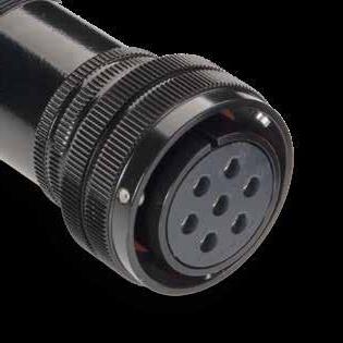
Designed to build a product even more suitable for the harshest application.
The studs of the plug connector coupling and a higher number of operations due to a lower wear of the coupling ramps.
CVBR series can be supplied from size 18 to size 40.
Main characteristics:
• Suitable for higher number of operations
• The roller-stud guarantees an easier coupling due to a lower wear of the coupling ramps
Available in several versions suitable for all applications and manufactured in different materials and finishes:
• Aluminum alloy with different types of protection finishes according to RoHS directives.
CVBR Series Code CVBR Bayonet Connector roller studs - for harsh applications
Shell Material - Aluminum 00 Shell Type
Flange/Plug Shell with ramp/threaded or with nut
DA Connector Class xx With backshell
T With plastic caps
FF Receptacle connector with threaded holes (to specify for 00/02/05 shell only)
T Connector Modification**
FP Receptacle connector with through holes (to specify for 03 shell only)
FS Receptacle connector with countersunk holes
V Insert and contacts sealed (solder only) PG16 Backshell Conduits size or internal thread - Without internal thread
F4
F7 Shell finish
Conduits size or internal thread
CCF - Green passivation - conductive
F5 Electroless nickel (RoHS compliance)
F7 Black epoxy varnish (RoHS compliance)
F16
CCF - Black passivation - conductive (RoHS compliance)
F26 Hard anodization (RoHS compliance)
G Panel Gasket - Without gasket
G With waterproof panel gasket
G2 With shielded panel gasket
G3 With waterproof shielded panel gasket
N Modification Code** N Contacts and hole plugs (Consult our sales office) S Customization (Consult our sales office)
311 Go online for data sheets & assembly instructions. Visit www.radiall.com/vansystem and enter the part number. GVJ SHELL CVBR SHELL
RF CVBR 00 DA 20-27 S X PG16 CR CD5 F7 G N T
xx
xx
Roller Stud
CVBR - Bayonet Connector roller studs - for harsh applications
Plug Connector (06) with Backshell Class (A - DA - RA)
Connector with backshell provided with an external thread suitable for MS3057…A or C type Cable-Clamps (to be ordered separately).
Roller Stud
“L”
312 Go online for data sheets & assembly instructions. Visit www.radiall.com/vansystem and enter the part number. GVJ SHELL CVBR SHELL
L ØB N ØQ Shell size ØQ ±0.2 ØB ±0.2 L max N Backshell Thread in inches 10SL 23.3 20 36 5/8”-24 UNEF 14S 29.5 24 43 3/4”-20 UNEF 16S 33 27 43 7/8”-20 UNEF 16 33 27 49 7/8”-20 UNEF 18 37 30 52 1”-20 UNEF 20 41 32 52.5 1” 3/16-18 UNEF 22 43 37 55 1” 3/16-18 UNEF 24 48 40 55 1” 7/16-18 UNEF 28 53 45 62 1” 7/16-18 UNEF 32 60 52 62 1” 3/4-18 UNS 36 66.2 58 62 2”-18 UNS 40 72.4 63.8 64 2”1/4-16 UN
different
the value indicated according to backshells accessories, wires size
some special insert configurations.
mm
Dimension
can be
from
and
Dimensions in
CVBR - Bayonet Connector roller studs - for harsh applications
Grommet (RA Class only)
Grommet cone (RA Class only)
RF Insulating material - Chloroprene rubber
Fluoride rubber
Silicone rubber RF Fire resistant rubber CVBR Series Code CVBR Bayonet Connector roller studs - for harsh applications Shell Material - Aluminum
With plastic caps 20-27 Insert Arrangement Size - Type S Contact Gender S Socket contacts P Pin contacts X Polarization Code** Alternate Positions CR Contact Termination - Solder contacts CR Crimp contacts
DA Connector Class
non watertight
with waterproof O-ring (IP67***)
with waterproof O-ring and grommet (IP67***) T Connector Modification**
P/N Sample:
LC Less contacts
CD5 Contact Plating - Silver plating
Modification Code**
CD5 Gold plating
F5 Electroless nickel (*)
F7 Black epoxy varnish (*)
F16
CCF - Black passivation (*) - conductive
F26 hard anodization (*)
Consult our sales office
313 Go online for data sheets & assembly instructions. Visit www.radiall.com/vansystem and enter the part number.
GVJ SHELL CVBR SHELL
Shell finish RF CVBR 06 DA 20-27 S X CR CD5 F7 N T Shell
ØB N
RF CVBR 06DAT 20-27SX CR CD5 F7 N Series Code Shell Type Connector Class
Material
Backshell
(*)
Gasket (DA-RA Class only)
RoHS compliance (**) If required *** Protection degree: IP 67 (only in the mating area with mated connectors) according to EN 60529
06
06 Plug Connector
A
DA
RA
V
S
Shell Type
T
F7 Shell finish
N
N
S
Plug Connector (06) with Backshell Class (AF - F)
Connector provided with backshell, MS3057...A type Cable-Clamp and bushing MS3420... (for single wire) CVBR - Bayonet Connector roller studs - for harsh applications
Dimension “L” can be different from the value indicated according to backshells accessories, wires size and some special insert configurations.
314 Go online for data sheets & assembly instructions. Visit www.radiall.com/vansystem and enter the part number. GVJ SHELL CVBR SHELL
ØQ L ØB A F Ø Shell size ØQ ±0.2 L max ØB ±0.2 A max ØF cable max dimension 10SL 23.3 46 20 22.5 5.6 14S 29.5 55 24 28 7.9 16S 33 56.5 27 30 11 16 33 62.5 27 30 11 18 37 67.5 30 31.7 14.2 20 41 68 32 37.5 15.8 22 43 70.5 37 37.5 15.8 24 48 70.5 40 43.5 19 28 53 77.5 45 43.5 19 32 60 77.5 52 51.7 23.8 36 66.2 77.5 58 58.5 31.7 40 72.4 93 63.8 68.5 34.9
Dimensions in mm IP54 Roller Stud
CVBR - Bayonet Connector roller studs - for harsh applications
Grommet cone (F Class only) Grommet (F Class only)
Insulating
Chloroprene
Socket contacts
Pin contacts
Polarization Code** Alternate Positions CR Contact Termination - Solder contacts CR Crimp contacts
LC Less contacts CD5 Contact Plating - Silver plating
CD5 Gold plating
F5 Electroless nickel (*)
F7 Black epoxy varnish (*)
F16 CCF - Black passivation (*) - conductive
F26 hard anodization (*)
315 Go online for data sheets & assembly instructions. Visit www.radiall.com/vansystem and enter the part number.
SHELL CVBR SHELL
GVJ
RF CVBR 06AFT 20-27SX CR CD5 F7 N
Code Shell Type
Class Shell finish RF CVBR 06 AF 20-27 S X CR CD5 F7 N T Shell Material
(*) RoHS compliance P/N Sample:
Series
Connector
Gasket H A F Ø ØB ØB A F Ø Cable-Clamp MS3057...A
MS3420
CVBR Series Code CVBR
harsh applications Shell Material - Aluminum 06 Shell Type 06 Plug Connector AF
Class AF with waterproof O-ring (IP54) F with waterproof O-ring and grommet (IP54)
T With plastic caps 20-27
Size - Type
S
Backshell
bushing
(**) If required RF
material -
rubber V Fluoride rubber S Silicone rubber RF Fire resistant rubber
Bayonet Connector roller studs - for
Connector
T Connector Modification**
Insert Arrangement
S Contact Gender
P
X
F7
Shell finish
N
N
S
Modification Code**
Consult our sales office
CVBR - Bayonet Connector roller studs - for harsh applications
Plug Connector (08) with 90° Elbow Class (A - DA - RA)
Connector with 90° elbow provided with an external thread suitable for MS3057…A or C type Cable-Clamps (to be ordered separately).
316 Go online for data sheets & assembly instructions. Visit www.radiall.com/vansystem and enter the part number. GVJ SHELL CVBR SHELL
ØQ L N H2 H1 Shell size ØQ ±0.2 L max H1 max H2 max N Backshell Thread in inches 10SL 23.3 45.5 27 38.7 5/8”-24 UNEF 14S 29.5 45.5 27 41.3 3/4”-20 UNEF 16S 33 47 29 44.9 7/8”-20 UNEF 16 33 56.5 29 44.9 7/8”-20 UNEF 18 37 57.5 31 48.1 1”-20 UNEF 20 41 60 33 51.7 1” 3/16-18 UNEF 22 43 62.5 35 55.3 1” 3/16-18 UNEF 24 48 65.5 38 59.8 1” 7/16-18 UNEF 28 53 65.5 40 65 1” 7/16-18 UNEF 32 60 70 46 74.1 1” 3/4-18 UNS 36 66.2 73.5 49 80.3 2”-18 UNS 40 72.4 78.5 53 87.6 2”1/4-16 UN Dimension “L” can be different from the value indicated according to backshells accessories, wires size and some special insert configurations. Dimensions in mm Roller Stud
CVBR - Bayonet Connector roller studs - for harsh applications
Insulating material
90° Elbow Grommet cone (RA Class only) (#) Grommet (RA Class only) Gasket (DA-RA Class only)
Chloroprene
resistant
with waterproof O-ring (IP67***)
with waterproof O-ring and grommet (IP67***)
T Connector Modification** T With plastic caps
20-27 Insert Arrangement Size - Type S Contact Gender S Socket contacts P Pin contacts
Polarization Code** Alternate Positions
Contact Termination - Solder contacts CR Crimp contacts LC Less contacts
CD5 Contact Plating - Silver plating
Modification Code**
Protection degree: IP 67 (only in the mating area with mated connectors) according to EN 60529
CD5 Gold plating
F5 Electroless nickel (*) F7 Black epoxy varnish (*)
F16 CCF - Black passivation (*)conductive
Consult our sales office
317 Go online for data sheets & assembly instructions. Visit www.radiall.com/vansystem and enter the part number.
SHELL CVBR SHELL N N
GVJ
(#)
some sizes
grommet cone
needed
RF CVBR 08DAT 20-27SX CR CD5 F7 N
Type
Class Shell finish RF CVBR 08 DA 20-27 S X CR CD5 F7 N T (*)
***
In
the
is not
P/N Sample:
Series Code Shell
Connector
RoHS compliance (**) If required
08
08
A
DA
RA
RF
-
rubber V Fluoride rubber S Silicone rubber RF Fire
rubber CVBR Series Code CVBR Bayonet Connector roller studs - for harsh applications Shell Material - Aluminum
Shell Type
Plug Connector with 90° elbow DA Connector Class
non watertight
(#)
X
CR
F7 Shell finish
N
N
S
318 Go online for data sheets & assembly instructions. Visit www.radiall.com/vansystem and enter the part number. SHELL
GVJ - Oversize Bayonet Connector - Shell - Backshell
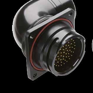
This series benefits of the bayonet coupling itself suitable for the harsh conditions typical in railway applications and of more robust and reliable features obtained by the following modifications.
Main characteristics:
• Bigger shell thicknesses to guarantee resistance against impact and harsh environment.
• Rubber-jacketed coupling nut also in the standard series. The roller studs make the coupling easier and allow a bigger number of operations due to a lower wear of the coupling ramps.
• Five key polarization system (a big key and four smaller).
• Increased dimensions to install insulators with bigger number of contacts (on equal service rating) or bigger contact sizes (for higher voltage).
• Wide range of rear accessories and adapters for all types of cables and protections available.
Available in several versions suitable for all applications and manufactured in different materials and finishes:
• Aluminum alloy with different types of protection finishes according to RoHS directives.
Flange/Plug Shell with ramp/threaded or with nut
Connector Class
Connector Modification**
Backshell Conduits size or internal thread
F7 Shell finish
Receptacle connector with threaded holes (to specify for 00/02/05 shell only)
Receptacle connector with through holes (to specify for 03 shell only) FS Receptacle connector with countersunk holes
Insert and contacts sealed (solder only)
Without internal thread
Conduits size or internal thread
F7 Black epoxy varnish (RoHS compliance)
F16 CCF - Black passivation - conductive (RoHS compliance)
F26 Hard anodization (RoHS compliance) - Gasket - Supplied with O Ring
Contacts and hole plugs (Consult our sales office)
Customization (Consult our sales office)
319 Go online for data sheets & assembly instructions. Visit www.radiall.com/vansystem and enter the part number. GVJ SHELL
RF GVJ 00 DA 20-27 S X PG16 CR CD5 F7 N T
GVJ Series Code GVJ Oversize Bayonet Connector
-
xx
Shell Material
Aluminum 00 Shell Type
T
DA
xx With backshell T
With plastic caps FF
FP
V
PG16
xx
-
N
N Modification Code**
S
GVJ - Oversize Bayonet Connector
Front Mounting Receptacle (00) with Backshell Class (A - DA - RA)
Connector with backshell provided with an external thread suitable for MS3057…A or C type Cable-Clamps (to be ordered separately).
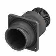
Panel cut out
For installation with backshell mounted, consult our sales office.
320 Go online for data sheets & assembly instructions. Visit www.radiall.com/vansystem and enter the part number. GVJ SHELL
Ø89 ±0.2 165 Max 2” 1/416 UN Ø8.5 110 90 8 43 Ø83 Ø89.8
Dimensions in mm R ØC ØT1 90 Ø76 Ø9
* *
Inserts Arrangement Insert Material Contacts Type N. Total Contacts Contacts Size/Current Rating Service Rating Code 4/0 225A 0 150A 4 80A 8 46A 12 23A 16 13A 18 7.5A 20 7.5A 48A4 Thermoplastic KT 4 4 D (1250 Vdc - 900 Vac) 48A7 Thermoplastic KT 6 4 2 A (700 Vdc - 500 Vac) 48-6 Rubber ST 6 3 3 A (700 Vdc - 500 Vac) 48A9 Rubber ST 9 3 2 4 (PD4 OV3) 400V 48A58 Rubber ST 58 1 57 A (700 Vdc - 500 Vac) 48A101 Rubber ST 101 101 A (700 Vdc - 500 Vac) Grommet Available
Dimension “L” can be different from the value indicated according to backshells accessories, wires size and some special insert configurations.
GVJ - Oversize Bayonet Connector
Series Code Shell Type Connector Class
RF Insulating materialChloroprene rubber or thermoplastic Inserts ****
RF Fire resistant rubber
GVJ Series Code GVJ Oversize Bayonet Connector with protected mating ramps Shell Material - Aluminum
DA Connector Class
non watertight
with waterproof O-ring (IP67***)
with waterproof O-ring and grommet (IP67***)
T Connector Modification** T With plastic capsReceptacle connector with through holes
Grommet cone (RA Class only) Grommet (RA Class only) Gasket (DA-RA Class only) **** Other insulating parts in fire resistant rubber
X Polarization Code** Alternate Positions
CR Contact Termination - Solder contacts CR Crimp contacts LC Less contacts
48-6 Insert Arrangement Size - Type S Contact Gender S Socket contacts P Pin contacts
CD5 Gold plating
CD5 Contact Plating - Silver plating
Shell finish F7 Black epoxy varnish (*) F16
CCF - Black passivation (*) - conductive F26 hard anodization (*) - Gasket - Supplied with O Ring N Modification Code**
Protection degree: IP 67 (only in the mating area with mated connectors) according to EN 60529
P/N
Consult our sales office
321 Go online for data sheets & assembly instructions. Visit www.radiall.com/vansystem and enter the part number. GVJ SHELL
Shell finish
RF GVJ 00 DA 48-6 S X CR CD5 F7 N T
(*)
Sample: RF GVJ 00DAT 48-6SX CR CD5 F7 N
Shell Material
RoHS compliance (**) If required ***
Backshell
00
00 Shell Type
Front mounting Receptacle
A
DA
RA
F7
N
S
GVJ - Oversize Bayonet Connector
Front Mounting Receptacle (00) with Backshell Class (AC - ACF)
Connector provided with backshell, MS3057...C type Cable-Clamp (for jacketed cable)
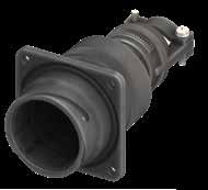
322 Go online for data sheets & assembly instructions. Visit www.radiall.com/vansystem and enter the part number. GVJ SHELL
Ø * Ø 63.5 Ø89 215 Max ±0.2 110 90 8 43 Ø83 Ø8.5 Ø89.8 * Ø min 3O - max 41,3 Dimension “L” can be different from the value indicated according to backshells accessories, wires size and some special insert configurations. Dimensions in mm R ØC ØT1 90 Ø76 Ø9 Panel cut out IP67 * * For installation with backshell mounted, consult our sales office. Inserts Arrangement Insert Material Contacts Type N. Total Contacts Contacts Size/Current Rating Service Rating Code 4/0 225A 0 150A 4 80A 8 46A 12 23A 16 13A 18 7.5A 20 7.5A 48A4 Thermoplastic KT 4 4 D (1250 Vdc - 900 Vac) 48A7 Thermoplastic KT 6 4 2 A (700 Vdc - 500 Vac) 48-6 Rubber ST 6 3 3 A (700 Vdc - 500 Vac) 48A9 Rubber ST 9 3 2 4 (PD4 OV3) 400V 48A58 Rubber ST 58 1 57 A (700 Vdc - 500 Vac) 48A101 Rubber ST 101 101 A (700 Vdc - 500 Vac) Grommet Available
GVJ - Oversize Bayonet Connector
Grommet (ACF Class only) Gasket
Grommet cone (ACF Class only)
RF Insulating materialChloroprene rubber or thermoplastic Inserts
RF Fire resistant rubber
GVJ Series Code GVJ Oversize Bayonet Connector with protected mating ramps Shell Material - Aluminum 00 Shell Type
Front mounting Receptacle AC Connector Class ACF with waterproof O-ring and grommet (IP67)
with waterproof O-ring (IP67) T Connector Modification** T With plastic capsReceptacle connector with through holes
Backshell
48-6 Insert Arrangement Size - Type S Contact Gender S Socket contacts P Pin contacts X Polarization Code** Alternate Positions
**** Other insulating parts in fire resistant rubber
CR Contact Termination - Solder contacts CR Crimp contacts
LC Less contacts
CD5 Contact Plating - Silver plating
F7 Shell finish
CD5 Gold plating
F7 Black epoxy varnish (*)
F16
CCF - Black passivation (*) - conductive
F26 hard anodization (*) - Gasket - Supplied with O Ring
Modification Code**
Consult our sales office
323 Go online for data sheets & assembly instructions. Visit www.radiall.com/vansystem and enter the part number.
SHELL
GVJ
(*) RoHS compliance
00ACT 48-6SX CR CD5 F7 N
Shell Type
Class Shell finish RF GVJ 00 AC 48-6 S X CR CD5 F7 N T Shell Material (**)
required
(*) 150 (*) 127 150 Ø89Max215Max GVJ06 GVJ08
P/N Sample: RF GVJ
Cable-Clamp MS3057...C Series Code
Connector
If
****
00
AC
N
N
S
GVJ - Oversize Bayonet Connector
Front Mounting Receptacle (00) with Backshell Class (DA..M
Connector with backshell provided with an internal Metric or PG thread suitable for Cable Glands or conduit adapters.
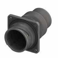
324 Go online for data sheets & assembly instructions. Visit www.radiall.com/vansystem and enter the part number. GVJ SHELL
- RA..M DA..PG - RA..PG) Ø89 ±0.2 165 Max Ø8.5 110 90 8 43 Ø83 Ø89.8 * 20 Max * M50 / M63 / M75 / PG48 Dimension
can be different from the value indicated according to backshells accessories,
size
some special insert configurations. Dimensions in mm R ØC ØT1 90 Ø76 Ø9 Panel cut out * * For installation
consult our sales office. Inserts Arrangement Insert Material Contacts Type N. Total Contacts Contacts Size/Current Rating Service Rating Code 4/0 225A 0 150A 4 80A 8 46A 12 23A 16 13A 18 7.5A 20 7.5A 48A4 Thermoplastic KT 4 4 D (1250 Vdc - 900 Vac) 48A7 Thermoplastic KT 6 4 2 A (700 Vdc - 500 Vac) 48-6 Rubber ST 6 3 3 A (700 Vdc - 500 Vac) 48A9 Rubber ST 9 3 2 4 (PD4 OV3) 400V 48A58 Rubber ST 58 1 57 A (700 Vdc - 500 Vac) 48A101 Rubber ST 101 101 A (700 Vdc - 500 Vac) Grommet Available
“L”
wires
and
with backshell mounted,
GVJ - Oversize Bayonet Connector
Code
Shell Material Backshell internal thread
GVJ Series Code
DA Connector Class
Oversize Bayonet Connector with protected mating ramps
with waterproof O-ring (IP67***)
with waterproof O-ring and grommet (IP67***)
T Connector Modification** T With plastic capsReceptacle connector with through holes 48-6 Insert Arrangement Size - Type
S Contact Gender S Socket contacts P Pin contacts
Other insulating parts in fire resistant rubber RF Insulating materialChloroprene rubber or thermoplastic Inserts
Polarization Code** Alternate Positions M12 Backshell internal thread M Provided with an internal Metric thread PG Provided with an internal PG thread
CR Contact Termination - Solder contacts CR Crimp contacts LC Less contacts
CD5 Contact Plating - Silver plating
CD5 Gold plating F7 Shell finish
F7 Black epoxy varnish (*)
F16 CCF - Black passivation (*) - conductive
F26 hard anodization (*) - Gasket - Supplied with O Ring N Modification Code** N Consult our sales office S
Protection degree: IP 67 (only in the mating area with mated connectors) according to EN
325 Go online for data sheets & assembly instructions. Visit www.radiall.com/vansystem and enter the part number. GVJ SHELL
Series
Shell Type Connector Class Shell finish
Grommet cone (RA..M RA..PG Class only) Grommet
RA..PG
only) Gasket P/N Sample: RF GVJ 00DAT 48-6SX M12 CR CD5 F7 N RF GVJ 00 DA 48-6 S X M12 CR CD5 F7 N T
(*)
required ***
****
Backshell
(RA..M
Class
RoHS compliance (**) If
60529 ****
RF Fire resistant rubber
-
00
GVJ
Shell Material
Aluminum 00 Shell Type
Front mounting Receptacle
DA
RA
X
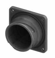
326 Go online for data sheets & assembly instructions. Visit www.radiall.com/vansystem and enter the part number. GVJ SHELL
-
be purchased separately) R ØC ØT 1 Panel cut out 65 M74x1,5 Ø8.5 110 90 8 43 Ø83 Ø89.8 Dimension “L” can be different from the value indicated according to backshells accessories, wires size and some special insert configurations. Dimensions in mm Inserts Arrangement Insert Material Contacts Type N. Total Contacts Contacts Size/Current Rating Service Rating Code 4/0 225A 0 150A 4 80A 8 46A 12 23A 16 13A 18 7.5A 20 7.5A 48A4 Thermoplastic KT 4 4 D (1250 Vdc - 900 Vac) 48A7 Thermoplastic KT 6 4 2 A (700 Vdc - 500 Vac) 48-6 Rubber ST 6 3 3 A (700 Vdc - 500 Vac) 48A9 Rubber ST 9 3 2 4 (PD4 OV3) 400V 48A58 Rubber ST 58 1 57 A (700 Vdc - 500 Vac) 48A101 Rubber ST 101 101 A (700 Vdc - 500 Vac) Grommet Available
GVJ
Oversize Bayonet Connector Front Mounting Receptacle (020) without Accessories (To
GVJ - Oversize Bayonet Connector
Oversize Bayonet Connector with protected mating ramps Shell Material
020 Shell Type
Front mounting Receptacle T Connector Modification**
With plastic caps - Receptacle connector with through holes 48-6 Insert Arrangement
- Type S Contact Gender
Socket contacts
Pin contacts
Polarization Code** Alternate Positions CR Contact Termination
Solder contacts
Crimp contacts
Less contacts
CD5 Contact Plating
F7 Shell finish
Gasket
Modification Code**
Silver plating CD5 Gold plating
F7 Black epoxy varnish (*)
F16 CCF - Black passivation (*) - conductive F26 hard anodization (*)
Supplied with O Ring
RoHS compliance
327 Go online for data sheets & assembly instructions. Visit www.radiall.com/vansystem and enter the part number. GVJ SHELL
(*)
RF
RF
P/N Sample: RF GVJ 020T 48-6SX CR CD5 F7 N (**) If required
Insulating material - Chloroprene rubber or thermoplastic Inserts ****
Fire resistant rubber
GVJ
-
GVJ Series Code
Aluminum
T
Size
-
CR
LC
020
S
P
X
-
N
N
S Series Code Shell Type Shell finish RF GVJ 020 48-6 S X CR CD5 F7 N T
-
-
Consult our sales office
GVJ - Oversize Bayonet Connector
Rear Mounting Receptacle (038) with 90° Elbow Class (A - DA - RA)
Connector with 90° elbow provided with an external thread suitable for MS3057…A or C type Cable-Clamps (to be ordered separately).
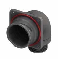
328 Go online for data sheets & assembly instructions. Visit www.radiall.com/vansystem and enter the part number. GVJ SHELL
100 125 2” 1/4 - 16 UN max 10 Ø8.5 110 90 8 43 Ø83 Ø89.8 155 Dimension “L” can be different from the value indicated according to backshells accessories, wires size and some special insert configurations. Dimensions in mm Inserts Arrangement Insert Material Contacts Type N. Total Contacts Contacts Size/Current Rating Service Rating Code 4/0 225A 0 150A 4 80A 8 46A 12 23A 16 13A 18 7.5A 20 7.5A 48A4 Thermoplastic KT 4 4 D (1250 Vdc - 900 Vac) 48A7 Thermoplastic KT 6 4 2 A (700 Vdc - 500 Vac) 48-6 Rubber ST 6 3 3 A (700 Vdc - 500 Vac) 48A9 Rubber ST 9 3 2 4 (PD4 OV3) 400V 48A58 Rubber ST 58 1 57 A (700 Vdc - 500 Vac) 48A101 Rubber ST 101 101 A (700 Vdc - 500 Vac) Grommet Available R ØC ØT1 90 Ø91.8 Ø9 Panel cut out * * For installation with backshell mounted, consult our sales office.
GVJ - Oversize Bayonet Connector
Shell Material
Series Code Shell Type Connector Class Shell finish
Gasket (DA-RA Class only)
Grommet (RA Class only)
Grommet cone (RA Class only)
RF Insulating materialChloroprene rubber or thermoplastic Inserts ****
RF Fire resistant rubber
GVJ Series Code GVJ
Oversize Bayonet Connector with protected mating ramps
Shell Material - Aluminum
038 Shell Type 038 Rear mounting Receptacle with 90° elbow
A non watertight
DA Connector Class
T Connector Modification**
DA with waterproof O-ring (IP67***)
RA with waterproof O-ring and grommet (IP67***)
T With plastic capsReceptacle connector with through holes
FF Receptacle connector with threaded holes
48-6 Insert Arrangement Size - Type
**** Other insulating parts in fire resistant rubber
Backshell
S Contact Gender S Socket contacts
P Pin contacts
X Polarization Code** Alternate Positions
CR Contact Termination
CD5 Contact Plating
F7 Shell finish
- Solder contacts
CR Crimp contacts
LC Less contacts
- Silver plating
CD5 Gold plating
F7 Black epoxy varnish (*)
F16
CCF - Black passivation (*) - conductive
F26 hard anodization (*) - Gasket - Supplied with O Ring
N Modification Code**
*** Protection degree: IP 67 (only in the mating area with mated connectors) according to EN 60529
P/N Sample:
Consult our sales office
329 Go online for data sheets & assembly instructions. Visit www.radiall.com/vansystem and enter the part number. GVJ SHELL
RF
038DAT 48-6SX CR CD5 F7 N RF GVJ 038 DA 48-6 S X CR CD5 F7 N T
GVJ
(*)
RoHS compliance (**) If required
N
S
GVJ - Oversize Bayonet Connector
Rear Mounting Receptacle (038) with 90° Elbow Class (AC - ACF)
Connector with 90° elbow provided with MS3057...C type Cable-Clamp (for jacketed cable)
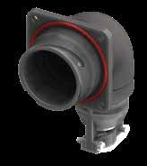
330 Go online for data sheets & assembly instructions. Visit www.radiall.com/vansystem and enter the part number. GVJ SHELL
Dimension “L” can be different from the value indicated according to backshells accessories, wires size and some special insert configurations. Dimensions in mm IP67 Inserts Arrangement Insert Material Contacts Type N. Total Contacts Contacts Size/Current Rating Service Rating Code 4/0 225A 0 150A 4 80A 8 46A 12 23A 16 13A 18 7.5A 20 7.5A 48A4 Thermoplastic KT 4 4 D (1250 Vdc - 900 Vac) 48A7 Thermoplastic KT 6 4 2 A (700 Vdc - 500 Vac) 48-6 Rubber ST 6 3 3 A (700 Vdc - 500 Vac) 48A9 Rubber ST 9 3 2 4 (PD4 OV3) 400V 48A58 Rubber ST 58 1 57 A (700 Vdc - 500 Vac) 48A101 Rubber ST 101 101 A (700 Vdc - 500 Vac) Grommet Available 150 125 Ø 63.5 Ø * 205 * Ø min 3O - max 41,3 Ø8.5 110 90 max 10 8 43 Ø83 Ø89.8 R ØC ØT1 90 Ø91.8 Ø9 Panel cut out * * For installation with backshell mounted, consult our sales office.
GVJ - Oversize Bayonet Connector
Grommet (ACF Class only) Gasket
Grommet cone (ACF Class only)
RF Insulating materialChloroprene rubber or thermoplastic Inserts
RF Fire resistant rubber
GVJ Series
Contact Gender
Oversize Bayonet Connector with protected mating ramps
Rear mounting Receptacle with 90° elbow
ACF Connector Class AC with waterproof O-ring (IP67) ACF with waterproof O-ring and grommet (IP67) T Connector Modification** T With plastic capsReceptacle connector with through holes FF Receptacle connector with threaded holes 48-6 Insert Arrangement Size - Type
**** Other insulating parts in fire resistant
Socket contacts P Pin contacts
Polarization Code** Alternate Positions
CR Contact Termination
CD5 Contact Plating
- Solder contacts
CR Crimp contacts
LC Less contacts
- Silver plating CD5 Gold plating
F7 Shell finish F7 Black epoxy varnish (*) F16 CCF - Black passivation (*) - conductive - Gasket - Supplied with O Ring N Modification Code**
Consult our sales office
331 Go online for data sheets & assembly instructions. Visit www.radiall.com/vansystem and enter the part number. GVJ SHELL curva 90° 90° elbow Connector provided with backshell, waterproof O-ringand :without grommet. :asAC class but with grommet. Ø89Max215Max GVJ06
(*) RoHS compliance
Sample: RF GVJ 038ACFT 48-6SX CR CD5 F7 N Series Code Shell Type Connector Class Shell finish RF GVJ 038 ACF 48-6 S X CR CD5 F7 N T (**)
required
P/N
If
Cable-Clamp MS3057...C 90° Elbow
rubber
****
Material -
Type 038
Code GVJ
Shell
Aluminum 038 Shell
S
S
X
N
S
GVJ - Oversize Bayonet Connector
Rear Mounting Receptacle (038) with 90° Elbow Class (DA..M - RA..M)
Connector with 90° elbow provided provided with an internal Metric or PG thread suitable for Cable Glands or conduit adapters.
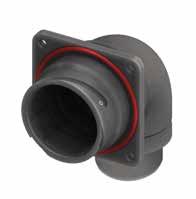
332 Go online for data sheets & assembly instructions. Visit www.radiall.com/vansystem and enter the part number. GVJ SHELL
100 125 max 10 Ø8.5 110 90 8 43 Ø83 Ø89.8 155 M50 14 Dimension “L” can be different from the value indicated according to backshells accessories, wires size and some special insert configurations. Dimensions in mm Inserts Arrangement Insert Material Contacts Type N. Total Contacts Contacts Size/Current Rating Service Rating Code 4/0 225A 0 150A 4 80A 8 46A 12 23A 16 13A 18 7.5A 20 7.5A 48A4 Thermoplastic KT 4 4 D (1250 Vdc - 900 Vac) 48A7 Thermoplastic KT 6 4 2 A (700 Vdc - 500 Vac) 48-6 Rubber ST 6 3 3 A (700 Vdc - 500 Vac) 48A9 Rubber ST 9 3 2 4 (PD4 OV3) 400V 48A58 Rubber ST 58 1 57 A (700 Vdc - 500 Vac) 48A101 Rubber ST 101 101 A (700 Vdc - 500 Vac) Grommet Available R ØC ØT1 90 Ø91.8 Ø9 Panel
* * For installation with backshell mounted, consult our sales office.
cut out
GVJ - Oversize Bayonet Connector
Shell Material
Gasket (DA-RA Class only)
Grommet (RA Class only)
Grommet cone (RA Class only)
RF Insulating materialChloroprene rubber or thermoplastic Inserts ****
RF Fire resistant rubber
GVJ Series Code GVJ
Oversize Bayonet Connector with protected mating ramps
Shell Material - Aluminum
038 Shell Type 038
Rear mounting Receptacle with 90° elbow
DA Connector Class A non watertight
DA with waterproof O-ring (IP67***)
RA with waterproof O-ring and grommet (IP67***)
**** Other insulating parts in fire resistant rubber M12
Series Code Shell Type Connector Class Shell finish
T Connector Modification**
T With plastic capsReceptacle connector with through holes
FF Receptacle connector with threaded holes
48-6 Insert Arrangement Size - Type
Backshell internal thread
Backshell
S Contact Gender S Socket contacts
X Polarization Code**
M12
P Pin contacts
Alternate Positions
Backshell internal thread M Provided with an internal Metric thread
CR Contact Termination
PG Provided with an internal PG thread
- Solder contacts
CR Crimp contacts
LC Less contacts
CD5 Contact Plating - Silver plating
F7 Shell finish
CD5 Gold plating
F7 Black epoxy varnish (*)
F16
CCF - Black passivation (*) - conductive
- Gasket - Supplied with O Ring N Modification Code** N
Consult our sales office S
*** Protection degree: IP 67 (only in the mating area with mated connectors) according to EN 60529
P/N Sample:
RoHS
(**) If
333 Go online for data sheets & assembly instructions. Visit www.radiall.com/vansystem and enter the part number. GVJ SHELL
RF GVJ 038DAT 48-6SX M12 CR CD5 F7 N RF GVJ 038 DA 48-6 S X CR CD5 F7 N T
(*)
compliance
required
GVJ - Oversize Bayonet Connector
Plug Connector with rubber covered coupling nut (06) with Backshell Class (A - DA - RA)
Connector with backshell provided with an external thread suitable for MS3057…A or C type Cable-Clamps (to be ordered separately). Rubber covered coupling nut able to protect against dust and impact; protected mating ramps.
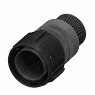
Available
Dimension “L” can be different from the value indicated according to backshells accessories, wires size and some special insert configurations.
334 Go online for data sheets & assembly instructions. Visit www.radiall.com/vansystem and enter the part number. GVJ SHELL
109 101 170 Max Ø89 ±0.2 2” 1/416 UN
Dimensions in mm Inserts Arrangement Insert Material Contacts Type N. Total Contacts Contacts Size/Current Rating Service Rating Code 4/0 225A 0 150A 4 80A 8 46A 12 23A 16 13A 18 7.5A 20 7.5A 48A4 Thermoplastic KT 4 4 D (1250 Vdc - 900 Vac) 48A7 Thermoplastic KT 6 4 2 A (700 Vdc - 500 Vac) 48-6 Rubber ST 6 3 3 A (700 Vdc - 500 Vac) 48A9 Rubber ST 9 3 2 4 (PD4 OV3) 400V 48A58 Rubber ST 58 1 57 A (700 Vdc - 500 Vac) 48A101 Rubber ST 101 101 A (700 Vdc - 500 Vac) Grommet
GVJ - Oversize Bayonet Connector
Connector Modification**
48-6 Insert Arrangement
Other insulating parts in fire resistant rubber RF Insulating materialChloroprene rubber or thermoplastic Inserts
P/N Sample:
RF Fire resistant rubber
Oversize Bayonet Connector with protected mating ramps
S Contact Gender S Socket contacts P Pin contacts
Polarization Code** Alternate Positions
CR Contact Termination
- Solder contacts CR Crimp contacts
LC Less contacts CD5 Contact Plating - Silver plating
CD5 Gold plating
F7 Black epoxy varnish (*)
CCF - Black passivation (*)
conductive F26 hard anodization (*)
Consult our sales office
-
335 Go online for data sheets & assembly instructions. Visit www.radiall.com/vansystem and enter the part number. GVJ SHELL
RF
06DAT 48-6SX CR CD5 F7 N Series Code Shell Type Connector Class Shell finish RF GVJ 06 DA 48-6 S X CR CD5 F7 N T
Grommet cone (RA
only) Grommet (RA Class only) Gasket (DA-RA Class only) (*) RoHS compliance
required ***
60529 ****
****
Series Code GVJ
Shell Material - Aluminum 06 Shell Type 06 Plug Connector DA
A non
DA
RA
T
GVJ
Backshell
Class
(**) If
Protection degree: IP 67 (only in the mating area with mated connectors) according to EN
GVJ
Connector Class
watertight
with waterproof O-ring (IP67***)
with waterproof O-ring and grommet (IP67***) T
With plastic caps
Size
Type
X
F7 Shell finish
N
N
S
F16
-
Modification Code**
GVJ - Oversize Bayonet Connector
Plug Connector with rubber covered coupling nut (06) with Backshell Class (AC - ACF)
Connector provided with backshell, MS3057...C type Cable-Clamp. (for jacketed cable)
Rubber covered coupling nut able to protect against dust and impact; protected mating ramps.
Grommet Available
336 Go online for data sheets & assembly instructions. Visit www.radiall.com/vansystem and enter the part number. GVJ SHELL
* Ø min 3O - max 41,3 Ø * Ø109 Ø101 Ø89 215 Max ±0.2 Ø 63.5 Dimension
can be different from the value indicated according
backshells accessories, wires size
some special insert configurations. Dimensions in mm IP67 Inserts Arrangement Insert Material Contacts Type N. Total Contacts Contacts Size/Current Rating Service Rating Code 4/0 225A 0 150A 4 80A 8 46A 12 23A 16 13A 18 7.5A 20 7.5A 48A4 Thermoplastic KT 4 4 D (1250 Vdc - 900 Vac) 48A7 Thermoplastic KT 6 4 2 A (700 Vdc - 500 Vac) 48-6 Rubber ST 6 3 3 A (700 Vdc - 500 Vac) 48A9 Rubber ST 9 3 2 4 (PD4 OV3) 400V 48A58 Rubber ST 58 1 57 A (700 Vdc - 500 Vac) 48A101 Rubber ST 101 101 A (700 Vdc - 500 Vac)
“L”
to
and
GVJ - Oversize Bayonet Connector
(ACF Class only)
RF Insulating materialChloroprene rubber or thermoplastic Inserts
resistant rubber
GVJ Series Code GVJ Oversize Bayonet Connector with protected mating ramps
ACF Connector Class
with waterproof O-ring (IP67)
with waterproof O-ring and grommet (IP67) T Connector Modification** T With plastic caps
48-6 Insert Arrangement Size - Type
Other insulating parts in fire resistant
S Contact Gender S Socket contacts P Pin contacts X Polarization Code** Alternate Positions
CR Contact Termination
- Solder contacts
CR Crimp contacts
LC Less contacts
CD5 Contact Plating - Silver plating
CD5 Gold plating F7 Shell finish
F7 Black epoxy varnish (*)
F16
Modification Code**
CCF - Black passivation (*) - conductive
F26 hard anodization (*)
Consult our sales office
337 Go online for data sheets & assembly instructions. Visit www.radiall.com/vansystem and enter the part number. GVJ SHELL (*) 150 (*) 127 150 Ø89Max215Max GVJ06 GVJ08
(*)
06ACFT 48-6SX CR CD5 F7 N Series Code Shell Type Connector Class Shell finish RF GVJ 06 ACF 48-6 S X CR CD5 F7 N T Backshell Grommet
Grommet
Gasket Cable-Clamp MS3057...C
****
RoHS compliance P/N Sample: RF GVJ
cone (ACF Class only)
(**) If required
rubber
****
RF Fire
06
06
Shell Material - Aluminum
Shell Type
Plug Connector
AC
ACF
N
S
N
GVJ - Oversize Bayonet Connector
Plug Connector with rubber covered coupling nut (06) with Backshell Class (DA..M - RA..M DA..PG - RA..PG)
Connector with backshell provided with an internal Metric or PG thread suitable for Cable Glands or conduit adapters. Rubber covered coupling nut able to protect against dust and impact; protected mating ramps.
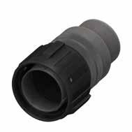
338 Go online for data sheets & assembly instructions. Visit www.radiall.com/vansystem and enter the part number. GVJ SHELL
Dimension “L” can be different from the value indicated according to backshells accessories, wires size and some special insert configurations. Dimensions in mm 170 Max Ø89 ±0.2 * 109 101 20 Max * M50 / M63 / M75 / PG48 Inserts Arrangement Insert Material Contacts Type N. Total Contacts Contacts Size/Current Rating Service Rating Code 4/0 225A 0 150A 4 80A 8 46A 12 23A 16 13A 18 7.5A 20 7.5A 48A4 Thermoplastic KT 4 4 D (1250 Vdc - 900 Vac) 48A7 Thermoplastic KT 6 4 2 A (700 Vdc - 500 Vac) 48-6 Rubber ST 6 3 3 A (700 Vdc - 500 Vac) 48A9 Rubber ST 9 3 2 4 (PD4 OV3) 400V 48A58 Rubber ST 58 1 57 A (700 Vdc - 500 Vac) 48A101 Rubber ST 101 101 A (700 Vdc - 500 Vac) Grommet
Available
GVJ - Oversize Bayonet Connector
Series Code Shell Type Connector Class Shell finish
Gasket
Grommet (RA..M RA..PG Class only)
RF Insulating materialChloroprene rubber or thermoplastic Inserts
RF Fire resistant rubber
GVJ Series Code GVJ Oversize Bayonet Connector with protected mating ramps
Shell Material - Aluminum 06 Shell Type 06 Plug Connector
DA Connector Class
with waterproof O-ring (IP67***)
with waterproof O-ring and grommet (IP67***)
T Connector Modification** T With plastic caps
48-6 Insert Arrangement Size - Type
Backshell internal thread
Grommet cone (RA..M RA..PG Class only)
Backshell
S Contact Gender S Socket contacts P Pin contacts X Polarization Code** Alternate Positions M12 Backshell internal thread M Provided with an internal Metric thread
CR Contact Termination
PG Provided with an internal PG thread
- Solder contacts
CR Crimp contacts
LC Less contacts
CD5 Contact Plating - Silver plating
F7 Shell finish
CD5 Gold plating
F7 Black epoxy varnish (*)
F16
CCF - Black passivation (*) - conductive
F26 hard anodization (*) N Modification Code**
Consult our sales office
RoHS compliance (**) If required *** Protection degree: IP 67 (only in the mating area with mated connectors) according to EN 60529 **** Other insulating parts in fire resistant rubber
P/N Sample:
339 Go online for data sheets
Visit www.radiall.com/vansystem and enter the part number.
SHELL
& assembly instructions.
GVJ
RF GVJ 06DAT 48-6SX M12 CR CD5 F7 N
RF
06 DA 48-6 S X CR CD5 F7 N T M12
GVJ
(*)
****
DA
RA
N
S
GVJ - Oversize Bayonet Connector
Plug Connector with rubber covered coupling nut (08) with 90° Elbow Class (A - DA - RA)
Connector with 90° elbow provided with an external thread suitable for MS3057…A or C type Cable-Clamps (to be ordered separately). Rubber covered coupling nut able to protect against dust and impact; protected mating ramps.
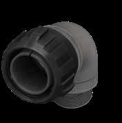
Grommet Available
“L”
and
340 Go online for data sheets & assembly instructions. Visit www.radiall.com/vansystem and enter the part number. GVJ SHELL
127 100 2” 1/4 - 16 UN 154.5 Ø109 Ø101
configurations. Dimensions in mm Inserts Arrangement Insert Material Contacts Type N. Total Contacts Contacts Size/Current Rating Service Rating Code 4/0 225A 0 150A 4 80A 8 46A 12 23A 16 13A 18 7.5A 20 7.5A 48A4 Thermoplastic KT 4 4 D (1250 Vdc - 900 Vac) 48A7 Thermoplastic KT 6 4 2 A (700 Vdc - 500 Vac) 48-6 Rubber ST 6 3 3 A (700 Vdc - 500 Vac) 48A9 Rubber ST 9 3 2 4 (PD4 OV3) 400V 48A58 Rubber ST 58 1 57 A (700 Vdc - 500 Vac) 48A101 Rubber ST 101 101 A (700 Vdc - 500 Vac)
Dimension
can be different from the value indicated according to backshells accessories, wires size
some special insert
GVJ - Oversize Bayonet Connector
RF Insulating materialChloroprene rubber or thermoplastic Inserts **** RF Fire resistant rubber
GVJ Series Code GVJ Oversize Bayonet Connector with protected mating ramps Shell Material - Aluminum
Shell Type
DA Connector Class
non watertight
with waterproof O-ring (IP67***)
with waterproof O-ring and grommet (IP67***) (#)
T Connector Modification** T With plastic caps
Other insulating parts in fire resistant rubber
48-6 Insert Arrangement Size - Type S Contact Gender S Socket contacts P Pin contacts X Polarization Code** Alternate Positions
CR Contact Termination
- Solder contacts
CR Crimp contacts
LC Less contacts
CD5 Contact Plating - Silver plating
CD5 Gold plating F7 Shell finish
F7 Black epoxy varnish (*)
F16 CCF - Black passivation (*)conductive N Modification Code**
Consult our sales office
Protection degree: IP 67 (only in the mating area with mated connectors) according to
341 Go online for data sheets & assembly instructions. Visit www.radiall.com/vansystem and enter the part number. GVJ SHELL
RF GVJ 08DAT 48-6SX CR CD5 F7 N Series Code Shell Type Connector Class Shell finish RF GVJ 08 DA 48-6 S X CR CD5 F7 N T (*)
compliance
required ***
60529 ****
90° Elbow Grommet cone (RA Class only) Grommet (RA Class only) Gasket (DA-RA Class only) P/N Sample:
RoHS
(**) If
EN
08
08
Plug Connector with 90° elbow
A
DA
RA
N
S
GVJ - Oversize Bayonet Connector
Plug Connector with rubber covered coupling nut (08) with 90° Elbow Class (AC - ACF)
Connector with 90° elbow provided with MS3057...C type Cable-Clamp (for jacketed cable) Rubber covered coupling nut able to protect against dust and impact; protected mating ramps.
342 Go online for data sheets & assembly instructions. Visit www.radiall.com/vansystem and enter the part number. GVJ SHELL
Dimension “L” can be different from the value indicated according to backshells accessories, wires size and some special insert configurations. Dimensions in mm IP67 Inserts Arrangement Insert Material Contacts Type N. Total Contacts Contacts Size/Current Rating Service Rating Code 4/0 225A 0 150A 4 80A 8 46A 12 23A 16 13A 18 7.5A 20 7.5A 48A4 Thermoplastic KT 4 4 D (1250 Vdc - 900 Vac) 48A7 Thermoplastic KT 6 4 2 A (700 Vdc - 500 Vac) 48-6 Rubber ST 6 3 3 A (700 Vdc - 500 Vac) 48A9 Rubber ST 9 3 2 4 (PD4 OV3) 400V 48A58 Rubber ST 58 1 57 A (700 Vdc - 500 Vac) 48A101 Rubber ST 101 101 A (700 Vdc - 500 Vac) Grommet Available Ø109 Ø101 Ø 63.5 127 150 Ø * 204.5 * Ø min 3O - max 41,3
GVJ - Oversize Bayonet Connector
waterproof
and grommet (IP67)
Connector Modification** T With plastic caps
Insert Arrangement
- Type S Contact Gender S Socket contacts P Pin contacts
Polarization Code** Alternate Positions CR Contact Termination - Solder contacts
Silver plating
Crimp contacts LC Less contacts CD5 Contact Plating
Black passivation (*) - conductive
sales office
343 Go online for data sheets & assembly instructions. Visit www.radiall.com/vansystem and enter the part number.
SHELL curva 90° 90° elbow Connector provided with backshell, waterproof O-ringand :without grommet. :asAC class but with grommet. Ø89Max215Max GVJ06
GVJ
(*) RoHS compliance P/N Sample: RF GVJ 08ACFT 48-6SX CR CD5 F7 N Series Code Shell Type Connector Class Shell finish RF GVJ 08 ACF 48-6 S X CR CD5 F7 N T (**) If required
Gasket Cable-Clamp MS3057...C 90° Elbow ****
in fire resistant rubber RF
-
rubber or
**** RF Fire resistant rubber GVJ Series Code GVJ
Connector
protected mating
Shell Material - Aluminum 08 Shell Type 08 Plug Connector with 90° elbow
AC with
ACF
Grommet cone (ACF Class only) Grommet (ACF Class only)
Other insulating parts
Insulating material
Chloroprene
thermoplastic Inserts
Oversize Bayonet
with
ramps
ACF Connector Class
waterproof O-ring (IP67)
with
O-ring
T
48-6
Size
X
CR
-
CD5 Gold plating F7 Shell finish F7 Black epoxy varnish (*) F16 CCF -
N Modification Code** N Consult our
S
GVJ - Oversize Bayonet Connector
Plug Connector with rubber covered coupling nut (08) with 90° Elbow Class (DA...M - RA...M)
Connector with 90° elbow provided with an internal Metric or PG thread suitable for Cable Glands or conduit adapters. Rubber covered coupling nut able to protect against dust and impact; protected mating ramps.
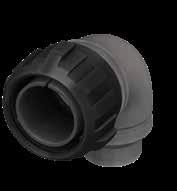
344 Go online for data sheets & assembly instructions. Visit www.radiall.com/vansystem and enter the part number. GVJ SHELL
127 100 154.5 Ø109 Ø101 M50 14 Dimension
can be different from the value indicated according to backshells accessories, wires size
some special insert configurations. Dimensions in mm Inserts Arrangement Insert Material Contacts Type N. Total Contacts Contacts Size/Current Rating Service Rating Code 4/0 225A 0 150A 4 80A 8 46A 12 23A 16 13A 18 7.5A 20 7.5A 48A4 Thermoplastic KT 4 4 D (1250 Vdc - 900 Vac) 48A7 Thermoplastic KT 6 4 2 A (700 Vdc - 500 Vac) 48-6 Rubber ST 6 3 3 A (700 Vdc - 500 Vac) 48A9 Rubber ST 9 3 2 4 (PD4 OV3) 400V 48A58 Rubber ST 58 1 57 A (700 Vdc - 500 Vac) 48A101 Rubber ST 101 101 A (700 Vdc - 500 Vac) Grommet Available
“L”
and
GVJ - Oversize Bayonet Connector
Gasket
Grommet (RA..M RA..PG Class only)
RF Insulating materialChloroprene rubber or thermoplastic Inserts **** RF Fire resistant rubber
GVJ Series Code GVJ Oversize Bayonet Connector with protected mating ramps
Grommet cone (RA..M RA..PG Class only)
DA Connector Class
with waterproof O-ring (IP67***)
with waterproof O-ring and grommet (IP67***) T Connector Modification** T With plastic caps
Other insulating parts in fire resistant rubber 90° Elbow
48-6 Insert Arrangement Size - Type S Contact Gender S Socket contacts P Pin contacts X Polarization Code** Alternate Positions M50 Backshell internal thread
Provided with an internal Metric thread PG Provided with an internal PG thread CR Contact Termination - Solder contacts CR Crimp contacts
LC Less contacts
CD5 Contact Plating - Silver plating
F7 Shell finish
CD5 Gold plating
F7 Black epoxy varnish (*)
F16 CCF - Black passivation (*)conductive N Modification Code**
Consult our sales office S
345 Go online for data sheets & assembly instructions. Visit www.radiall.com/vansystem and enter the part number. GVJ SHELL
CR
Shell finish RF GVJ 08 DA 48-6 S X CR CD5 F7 N T M50
(*) RoHS compliance (**) If required ***
mating
according to EN 60529
P/N Sample: RF GVJ 08DAT 48-6SX M50
CD5 F7 N Series Code Shell Type Connector Class
Backshell internal thread
Protection degree: IP 67 (only in the
area with mated connectors)
****
08
08 Plug
90° elbow
DA
RA
Shell Material - Aluminum
Shell Type
Connector with
M
N
GVJG - Oversize Bayonet Connector with external insulated coating
Plug Connector with rubber covered coupling nut (06) with Backshell Class (DA..M - RA..M)
Connector with backshell provided with an internal Metric thread suitable for Cable Glands or conduit adapters. Rubber covered coupling nut able to protect against dust and impact; protected mating ramps.
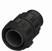
346 Go online for data sheets & assembly instructions. Visit www.radiall.com/vansystem and enter the part number. GVJG SHELL
Dimension “L” can be different from the value indicated according to backshells accessories, wires size and some special insert configurations. Dimensions in mm Inserts Arrangement Insert Material Contacts Type N. Total Contacts Contacts Size/Current Rating Service Rating Code 4/0 225A 0 150A 4 80A 8 46A 12 23A 16 13A 18 7.5A 20 7.5A 48A4 Thermoplastic KT 4 4 D (1250 Vdc - 900 Vac) 48A7 Thermoplastic KT 6 4 2 A (700 Vdc - 500 Vac) 48-6 Rubber ST 6 3 3 A (700 Vdc - 500 Vac) 48A9 Rubber ST 9 3 2 4 (PD4 OV3) 400V 48A58 Rubber ST 58 1 57 A (700 Vdc - 500 Vac) 48A101 Rubber ST 101 101 A (700 Vdc - 500 Vac) Grommet Available 175 Max M63 109 101
GVJG - Oversize Bayonet Connector with external insulated coating
Series Code Shell Type Connector Class Shell finish RF GVJG 06
Backshell internal thread
Grommet cone (RA Class only) Grommet (RA Class only) Gasket
RF Insulating materialChloroprene rubber or thermoplastic Inserts ****
RF Fire resistant rubber
GVJG Series Code GVJG Oversize Bayonet Connector with protected mating ramps and external insulated coating Shell Material - Aluminum
06 Shell Type 06 Plug Connector
DA Connector Class DA with waterproof O-ring (IP67***) RA with waterproof O-ring and grommet (IP67***)
T Connector Modification** T With plastic caps
48-6 Insert Arrangement Size - Type
Backshell
S Contact Gender S Socket contacts P Pin contacts
X Polarization Code** Alternate Positions
M63 Backshell internal thread M Provided with an internal Metric thread
CR Contact Termination - Solder contacts
CD5 Contact Plating
F7 Shell finish
CR Crimp contacts
LC Less contacts
- Silver plating
CD5 Gold plating
F7 Black epoxy varnish (*)
F16
CCF - Black passivation (*) - conductive
F26 hard anodization (*) N Modification Code** N
Consult our sales office S
*** Protection degree: IP 67 (only in the mating area with mated connectors) according to EN 60529 **** Other insulating parts in fire resistant rubber
P/N Sample: RF GVJG 06DAT 48-6SX M63 CR CD5 F7 N
RoHS
(**) If
347 Go online for data sheets
Visit www.radiall.com/vansystem and enter the part number.
& assembly instructions.
GVJG SHELL
48-6 S X CR CD5 F7 N T M63
DA
(*)
compliance
required
Connector Shell - Receptacle mounting holes option
FF Connector Modification
FF Receptacle connector with threaded holes (to specify for 00/02/020/05 shell only)
FP Receptacle connector with through holes (to specify for 03/030/038/TB shell only)
FS Receptacle connector with countersunk holes
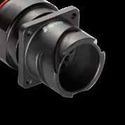
The front/rear mounting panel connectors as well as through-bulkhead connectors and dummy receptacles can be also supplied with different mounting holes. Please refer to the dimensional tables below. Dimensions
Shell size
Front mounting panel connectors
Shell version: 00 - 020 - 02 - 05
holes
*
348 Go online for data sheets & assembly instructions. Visit www.radiall.com/vansystem and enter the part number. SHELL
Threaded
FF Countersunk holes FS Through holes Standard Version T1 T2 T3 T 10SL M4 3.2 6.5 3.1 14S M4 3.2 6.5 3.1 16S M4 3.2 6.5 3.1 16 M4 3.2 6.5 3.1 18 M4 3.2 6.5 3.1 20 M4 3.2 6.5 3.1 22 M4 3.2 6.5 3.1 24 M5* 3.7 7.5 3.7 28 M5 3.7 7.5 3.7 32 M5 4.3 8 4.4 36 M5 4.3 8.5 4.4 40 M5 4.3 8.5 4.4 GVJ - - - 8.5 T 0.1 T2 90° T T1 T3
in mm
M5 front mounting panel, M4 Real mounting panel Shell size Rear mounting panel connectors Shell version: 03 - 030 - 038 - TB Through holes FP - T Threaded holes Standard Version T1 Threaded holes FF - T1 Through holes Standard Version T 10SL 3.2 M4 -14S 3.2 M4 -16S 3.2 M4 -16 3.2 M4 -18 3.2 M4 -20 3.2 M4 -22 3.2 M4 -24 3.7 M4* -28 3.7 M5 -32 4.3 M5 -36 4.3 M5 -40 4.3 M5 -GVJ - - M8 8.5 T T T1 T 0.1 T2 90° T T1 T3
CR
20-27 S
F7 FF DA 00 CVB
Connector Shell - Panel drilling dimensions
Panel cut out
Shell size R Shell version: 00 - 020 - 02 * Shell version: 03 - 030 - 038 - TB
* For use with backshell mounted and accessories, consult our sales office.
Panel cut out
349 Go online for data
Visit www.radiall.com/vansystem and enter the part number. SHELL R ØC ØT 1
sheets & assembly instructions.
ØC ±0.2 ØT1 for FP Through holes (standard hole)
FS Countersunk holes ØT1 for FF Threaded holes ØC ±0.2 ØT1 for FF Threaded holes (standard hole) ØT1 for FP Through holes 10SL 18.2 17 3.4 4.5 19.1 4.5 3.4 14S 23 20 3.4 4.5 25.5 4.5 3.4 16S 24.6 23 3.4 4.5 28.3 4.5 3.4 16 24.6 23 3.4 4.5 28.3 4.5 3.4 18 27 26.5 3.4 4.5 31.7 4.5 3.4 20 29.4 30 3.4 4.5 35 4.5 3.4 22 31.8 33 3.4 4.5 38.3 4.5 3.4 24 34.9 36 3.9 5.5 41.8 4.5 3.9 28 39.7 42 3.9 5.5 47.6 5.5 3.9 32 44.5 48.5 4.5 5.5 54.3 5.5 4.5 36 49.2 55 4.5 5.5 60.5 5.5 4.5 40 55.6 61 4.5 5.5 66.4 5.5 4.5 GVJ 90 76 9 - 91.8 8.5 (on request) 9 (standard) Dimensions
mm
Shell size Shell version: 07
070
ØC -0 +0.25 A +0 -0.35 10SL 22.4 21 14S 28.75 27.4 16S 31.95 30.95 16 31.95 30.95 18 35.1 33.75 20 38.3 36.85 22 41.45 40.05 24 44.65 43.35 28 51 49.55 32 57.35 55.95 36 63.7 62.35 40 70.05 68.55
and
in
-
- 078
ØC A
If required the nut can be lock with optional screws
Connector Shell - Mounting panel characteristics
Panel Thickness *
Shell size Shell version: 03 - 030 - 038 Rear Mounting Panel Connectors
Shell version: 07 - 070 - 078 Jam Nut Rear Mounting Panel Connectors
Shell version: TB Through bulkhead, gasket side mounting connectors
350 Go online for data sheets & assembly instructions. Visit www.radiall.com/vansystem and enter the part number. SHELL
P
Max Min Max Max 10SL 6 2.4 5.2 10 14S 7.2 2.7 7.5 9.6 16S 7.2 2.4 7.5 9.6 16 5.35 2.4 7.5 13.8 18 7.25 2.4 9 13 20 7.3 2.4 8.1 13 22 7.3 2.4 9.1 12.25 24 6.85 2.4 9.1 11.25 28 7.8 2.4 8.5 12.4 32 7.5 2.4 6.5 9 36 7.5 2.4 8.3 8.3 40 7.5 2.4 8.3 9 GVJ 10 - -P Dimensions in mm *
For use with no rubber covered nut For use with shell type GG coupling nut rubber covered (or shell type 61 or 81), please consult our sales office.
Contacts - Part number explanation
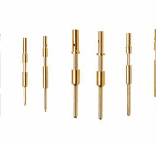
351 Go online for data sheets & assembly instructions. Visit www.radiall.com/vansystem and enter the part number. CONTACTS
P/N Sample: ST485 16-13S CD5 ST Contact Type ST Contact for rubber insert KT Contact for thermoplastic insert CC Coaxial contact TC1 - TC2 - TC3 - TC4 Contact for thermocouple 485 Contact Termination 385 Solder 485 Crimp 585 For Lug XX Contact Size # xx Contact size L Connection type L With Louver XX Non-standard diameter xx For special wires S Contact Gender S Socket P Pin CLE Variation TP Touch Proof CLE Close Entry FM FMLB (long contacts) AO Advance opening (short contacts) CD5 Contact Plating - Silver Plated CD5 Gold Plated N_ Modification Code Nxx Modification Code ST 485 XX L XX S CLE CD5 N_ Contact AWG Rated Current** 20 26 2A 20 24 3A 20 22 5A 20 20 7,5A 18 20 10A 16 20 7,5A 16 18 10A 16 16 13A 16 12 13A 12 20 7,5A 12 18 7,5A 12 16 13A 12 14 17A 12 12 23A 8 16 13A 8 12 23A 8 10 33A 8 8 46A 4 10 33A 4 6 60A 4 4 80A 0 8 46A 0 2 100A 0 0 150A 4/0 0 150A 4/0 4/0 225A ** Valid for ambient temperature at 80°C # The creepage distance is reduced for the insert with contacts for larger wires than the standard ones. Consult our commercial office for Service Rating. The contacts with reduced ØD for smaller wire may be a sealing problem with grommets. The contacts with enlarged ØD for larger wires may be difficulties with grommets. Please contact our sales office.
Solder Contacts - ST - For Rubber insert
Pin Contacts - Silver Plated
Socket Contacts - Silver Plated
352 Go online for data sheets & assembly instructions. Visit www.radiall.com/vansystem and enter the part number. CONTACTS Contact size Part Number Short Description AWG Cable size ØA ØE ØC1 ØC2 ØD1 ØD2 H1 H2 L 16S VS702001 ST385 16SP 18÷16 3.2 1.58 1.8 - 2.6 - 5.5 - 25.7 16 VS702002 ST385 16P 18÷16 3.2 1.58 1.8 - 2.6 - 7 - 32.1 12 VS702003 ST385 12P 12 4.8 2.38 2.9 - 3.7 - 8 - 36.6 8 VS702004 ST385 8P 8 7.8 3.6 - 5.3 - 6.6 - 12.6 36.6 4 VS702005 ST385 4P 4 11 5.7 - 8.5 - 10 - 16.5 36.6 0 VS702006 ST385 0P 0 15.1 9.05 - 11.5 - 14 - 14 44.5 Contact size Part Number Short Description AWG Cable size ØA ØE ØC1 ØC2 ØD1 ØD2 H1 H2 L 16S VS702011 ST385 16SS 18÷16 3.2 1.65 1.8 - 2.6 - 5.5 - 25.4 16 VS702012 ST385 16S 18÷16 3.2 1.65 1.8 - 2.6 - 7 - 36.6 12 VS702013 ST385 12S 12 4.8 2.48 2.9 - 3.7 - 8 - 36.6 8 VS702014 ST385 8S 8 7.8 3.7 - 5.25 - 6.55 - 12.7 36.6 4 VS702015 ST385 4S 4 11 5.8 - 8.5 - 10 - 12 36.6 0 VS702016 ST385 0S 0 15.1 9.17 - 11.5 - 14 - 14 44.5
Dimensions in mm L ØE ØD1 ØC1 H1 ØA ØD2 ØE ØC2 L ØE ØD1 ØC1 ØA H1 L L H2 H2 ØA ØD2 ØE ØC2 ØA L ØE ØD1 ØC1 H1 ØA ØD2 ØE ØC2 L ØE ØD1 ØC1 ØA H1 L L H2 H2 ØA ØD2 ØE ØC2 ØA
Solder Contacts - ST - For Rubber insert
Pin Contacts - Gold Plated
Socket Contacts - Gold Plated
353 Go online for data sheets & assembly instructions. Visit www.radiall.com/vansystem and enter the part number. CONTACTS Contact size Part Number Short Description AWG Cable size ØA ØE ØC1 ØC2 ØD1 ØD2 H1 H2 L 16S VS702021 ST385 16SP CD5 18÷16 3.2 1.58 1.8 - 2.6 - 5.5 - 25.7 16 VS702022 ST385 16P CD5 18÷16 3.2 1.58 1.8 - 2.6 - 7 - 32.1 12 VS702023 ST385 12P CD5 12 4.8 2.38 2.9 - 3.7 - 8 - 36.6 8 VS702024 ST385 8P CD5 8 7.8 3.6 - 5.3 - 6.6 - 12.6 36.6 4 VS702025 ST385 4P CD5 4 11 5.7 - 8.5 - 10 - 16.5 36.6 0 VS702026 ST385 0P CD5 0 15.1 9.05 - 11.5 - 14 - 14 44.5 Contact size Part Number Short Description AWG Cable size ØA ØE ØC1 ØC2 ØD1 ØD2 H1 H2 L 16S VS702031 ST385 16SS CD5 18÷16 3.2 1.65 1.8 - 2.6 - 5.5 - 25.4 16 VS702032 ST385 16S CD5 18÷16 3.2 1.65 1.8 - 2.6 - 7 - 36.6 12 VS702033 ST385 12S CD5 12 4.8 2.48 2.9 - 3.7 - 8 - 36.6 8 VS702034 ST385 8S CD5 8 7.8 3.7 - 5.25 - 6.55 - 12.7 36.6 4 VS702035 ST385 4S CD5 4 11 5.8 - 8.5 - 10 - 12 36.6 0 VS702036 ST385 0S CD5 0 15.1 9.17 - 11.5 - 14 - 14 44.5
Dimensions in mm L ØE ØD1 ØC1 H1 ØA ØD2 ØE ØC2 L ØE ØD1 ØC1 ØA H1 L L H2 H2 ØA ØD2 ØE ØC2 ØA L ØE ØD1 ØC1 H1 ØA ØD2 ØE ØC2 L ØE ØD1 ØC1 ØA H1 L L H2 H2 ØA ØD2 ØE ØC2 ØA
Crimp Contacts - ST - For Rubber insert
Pin Contacts - Silver Plated
New Contacts
See notes page “Contacts - Part number explanation” for contacts with ØD different from standard
354 Go online for data sheets & assembly instructions. Visit www.radiall.com/vansystem and enter the part number. CONTACTS Contact Size Part Number Short Description Wire section (mm2) AWG cable size ØA ØE ØC ØD H L 20 VS701600 ST485 20P/1(a)** 0.15÷0.3 26÷22 2 1 0.9 1.6 4 32.5 20 VS701601 ST485 20P/2(b)** 0.15÷0.3 26÷22 2 1 0.9 1.6 4 24.6 20 VS701602 ST485 20P/3(C)** 0.15÷0.3 26÷22 2 1 0.9 1.6 4 29.9 18 VS701603 ST485 18P 0.15÷0.6 26÷20 2.2 1.42 1.3 1.93 4.5 29.6 16S VS701604 ST485 16SP 1÷1.5 18÷16 3.2 1.58 1.7 2.6 6.5 26.6 16S VS701655 ST485 16S-11P # 0.25÷0.5 22-20 3.2 1.58 1.1 2.15 6.5 26.6 16S VS701605 ST485 16S-12P # 0.15÷0.75 20 3.2 1.58 1.2 2.6 6.5 26.6 16S VS701607 ST485 16S-15P # 0.75÷1 18 3.2 1.58 1.5 2.6 6.5 26.6 16S VS701656 ST485 16S-17P # 0.75 - 3.2 1.58 1.75 2.62 6.5 26.6 16S VS701660 ST485 16S-19P # 1.5÷2.5 16÷14 3.2 1.58 1.9 2.5 6.5 26.6 16S VS701608 ST485 16S-20P # 1÷2 18÷14 3.2 1.58 2 2.9 6.5 26.6 16S VS701609 ST485 16S-26P # 2.5÷3 12 3.2 1.58 2.5 3.8 7 27 16 VS701610 ST485 16P 1÷1.5 18÷16 3.2 1.58 1.7 2.6 6.5 31.75 16 VS701611 ST485 16-08P** # 0.15÷0.2 26÷24 3.2 1.58 0.85 1.55 6.35 31.75 16 VS701612 ST485 16-12P # 0.15÷0.75 20 3.2 1.58 1.2 2.6 6.35 31.75 16 VS701613 ST485 16-13P # 0.15÷0.6 26÷20 3.2 1.58 1.3 1.93 6.35 31.75 16 VS701659 ST485 16-14P # 0.75 18 3.2 1.58 1.35 2.2 6.4 31.75 16 VS701614 ST485 16-15P # 0.75÷1 18 3.2 1.58 1.5 2.6 6.35 31.75 16 VS701661 ST485 16-17P # 0.5÷1.5 20÷16 3.2 1.58 1.7 2.3 6.36 36.5 16 VS701662 ST485 16-19P # 1.5÷2.5 16÷14 3.2 1.58 1.9 2.5 6.36 36.5 16 VS701615 ST485 16-20P # 1÷2 18÷14 3.2 1.58 2 2.9 6.35 31.75 16 VS701616 ST485 16-26P # 2.5÷3 12 3.2 1.58 2.5 3.8 7 31.75 12 VS701657 ST485 12-11P # 0.5 22-20 4.8 2.38 1.1 3 8.5 37.5 12 VS701617 ST485 12-12P # 0.15÷0.75 20 4.8 2.38 1.2 2.6 8.5 37.5 12 VS701618 ST485 12-15P # 0.75÷1 18 4.8 2.38 1.5 3.4 8.5 37.5 12 VS701619 ST485 12-20P # 1÷2 18÷14 4.8 2.38 2 3.8 6.5 37.5 12 VS701620 ST485 12-22P # 2.5 - 4.8 2.38 2.2 3.8 8.5 37.5 12 VS701621 ST485 12P 3 12 4.8 2.38 2.5 3.8 8.5 37.5 12 VS701622 ST485 12-30P # 4 - 4.8 2.38 3 4.8 8.5 37.5 12 VS701623 ST485 12-38P # 6 - 4.8 2.38 3.6 4.8 8 37.5 8 VS701624 ST485 8P - 8 7.8 3.6 4.55 6.8 12.2 40.7 8 VS701625 ST485 8-15P** # 1 18 7.8 3.6 1.5 3.4 8.5 40.7 8 VS701626 ST485 8-18P** # 1÷2 18÷14 7.8 3.6 1.8 3.8 8.5 40.7 8 VS701646 ST485 8-22P # 2.5 - 7.8 3.6 2.2 3.8 12.2 40.7 8 VS701647 ST485 8-26P # 3 12 7.8 3.6 2.5 3.8 12.2 40.7 8 VS701627 ST485 8-30P # 4 - 7.8 3.6 3 4.8 8.3 40.7 8 VS701628 ST485 8-38P # 6 10 7.8 3.6 3.6 6.8 12.2 40.6 8 VS701629 ST485 8-50P # 10 - 7.8 3.6 5 6.8 12.2 40.7 4 VS701630 ST485 4P 22 4 11 5.7 7.1 9.55 12.2 41.25 4 VS701631 ST485 4-26P** # 3 - 11 5.7 2.5 3.8 8.5 41.25 4 VS701632 ST485 4-30P** # 4 - 11 5.7 3 4.8 8.5 41.25 4 VS701648 ST485 4-38P # 6 10 11 5.7 3.6 6.8 12.2 41.25 4 VS701633 ST485 4-50P # 10 - 11 5.7 5 6.8 12.2 41.25 4 VS701634 ST485 4-58P # - 6 11 5.7 5.8 7.8 12.2 41.25 4 VS701635 ST485 4-62P # 16 - 11 5.7 6.2 9.5 12.2 41.25 4 VS701649 ST485 4-78P # 25 - 11 5.7 7.8 9.55 12.2 41.25 4 VS701650 ST485 4-90P # 35 2 11 5.7 9 14.35 14 41.25 0 VS701636 ST485 0P 53 0 15.1 9.05 11.5 14.35 14.5 45 0 VS701637 ST485 0-45P # - 8 15.1 9.05 4.55 6.8 12.2 44.5 0 VS701658 ST485 0-50P # 10 - 15.1 9.05 5 7 12.2 44.5 0 VS701651 ST485 0-58P # - 6 15.1 9.05 5.8 7.8 14 44.5 0 VS701652 ST485 0-62P # 16 - 15.1 9.05 6.2 9.5 12.2 44.5 0 VS701638 ST485 0-78P # 25 - 15.1 9.05 7.8 9.5 14 44.5 0 VS701653 ST485 0-80P # - 3 15.1 9.05 8 10 14 44.5 0 VS701639 ST485 0-90P # 35 2 15.1 9.05 9 14.35 13.6 44.5 0 VS701640 ST485 0-107P # 50 - 15.1 9.05 10.7 14.35 14.5 44.5 0 VS701654 ST485 0-135P # 67.4 2/0 15.1 9.05 13.5 16.5 18 51.9 4/0 VS701641 ST485 4/0-115P # 53 0 20 12.73 11.5 14.35 16.3 58.5 4/0 VS701642 ST485 4/0-135P # 67.4 2/0 20 12.73 13.5 16.5 18 58.5 4/0 VS701643 ST485 4/0-144P # 70 - 20 12.73 14.4 20 20 58.5 4/0 VS701644 ST485 4/0-155P # 95 - 20 12.73 15.2 19.7 20 58.5 4/0 VS701645 ST485 4/0P 107÷120 4/0 20 12.73 15.2 19.7 20 58.5
L L H H H H ø A ø E ø C ø D ø C ø D ø A ø E ø A ø E ø A ø E ø C ø C L L ø D ø D **
consult our Sales Office) Dimensions in mm (a)
(b)
On request (please
For arrangement 40A201
For arrangements 24A55, 28-72, 32A101 and 28A31 (c) For arrangement 22A24
#
Crimp Contacts - ST - For Rubber insert
Socket Contacts - Silver Plated
On request (please consult our Sales Office) (a) For all arrangements with contacts size 20 Dimensions in mm
Close entry contact type
# See notes page “Contacts - Part number explanation” for contacts with ØD different from standard
355 Go online for data sheets & assembly
Visit www.radiall.com/vansystem and enter the part number. CONTACTS Contact Size Part Number Short Description Wire section (mm2) AWG cable size ØA ØE ØC ØD H L 20 VS701500 ST485 20S(a)** / * 0.15÷0.3 26÷22 2 1.15 0.9 1.6 4 32.5 - - - - - - - - - -- - - - - - - - - -18 VS701503 ST485 18S * 0.15÷0.6 26÷20 2.4 1.46 1.3 1.93 4.5 34.4 16S VS701504 ST485 16SS 1÷1.5 18÷16 3.2 1.68 1.7 2.6 6.35 27 16S VS701555 ST485 16S-11S # 0.25÷0.5 22-20 3.2 1.68 1.1 2.15 6.5 26.6 16S VS701505 ST485 16S-12S # 0.15÷0.75 20 3.2 1.68 1.2 2.6 6.5 26.6 16S VS701507 ST485 16S-15S # 0.75÷1 18 3.2 1.68 1.5 2.6 6.5 26.6 16S VS701556 ST485 16S-17S # 0.75 - 3.2 1.68 1.75 2.62 6.5 26.6 16S VS701560 ST485 16S-19S # 1.5÷2.5 16÷14 3.2 1.68 1.9 2.5 6.5 26.6 16S VS701508 ST485 16S-20S # 1÷2 18÷14 3.2 1.68 2 2.9 6.5 27 16S VS701509 ST485 16S-26S # 2.5÷3 12 3.2 1.68 2.5 3.8 7 27 16 VS701510 ST485 16S 1÷1.5 18÷16 3.2 1.68 1.7 2.6 6.5 36.5 16 VS701511 ST485 16-08S** # 0.15÷0.2 26÷24 3.2 1.68 0.85 1.55 6.35 36.5 16 VS701512 ST485 16-12S # 0.15÷0.75 20 3.2 1.68 1.2 2.6 6.5 36.5 16 VS701513 ST485 16-13S # 0.15÷0.6 26÷20 3.2 1.68 1.3 1.93 6.35 36.5 16 VS701559 ST485 16-14S # 0.75 18 3.2 1.68 1.35 2.2 6.4 36.5 16 VS701514 ST485 16-15S # 0.75÷1 18 3.2 1.68 1.5 2.6 6.5 36.5 16 VS701561 ST485 16-17S # 0.5÷1.5 20÷16 3.2 1.68 1.7 2.3 6.36 36.5 16 VS701562 ST485 16-19S # 1.5÷2.5 16÷14 3.2 1.68 1.9 2.5 6.36 36.5 16 VS701515 ST485 16-20S # 1÷2 18÷14 3.2 1.68 2 2.9 6.5 36.5 16 VS701516 ST485 16-26S # 2.5÷3 12 3.2 1.68 2.5 3.8 7 36.5 12 VS701557 ST485 12-11S # 0.5 22-20 4.8 2.48 1.1 3 8.5 37.5 12 VS701517 ST485 12-12S # 0.15÷0.75 20 4.8 2.48 1.2 2.6 8.5 37.5 12 VS701518 ST485 12-15S # 0.75÷1 18 4.8 2.48 1.5 3.4 8.5 37.5 12 VS701519 ST485 12-20S # 1÷2 18÷14 4.8 2.48 2 3.8 6.5 37.5 12 VS701520 ST485 12-22S # 2.5 - 4.8 2.48 2.2 3.8 8.5 37.5 12 VS701521 ST485 12S 3 12 4.8 2.48 2.5 3.8 8.5 37.5 12 VS701522 ST485 12-30S # 4 - 4.8 2.48 3 4.8 8.5 37.5 12 VS701523 ST485 12-38S # 6 - 4.8 2.48 3.6 4.8 8.5 37.5 8 VS701524 ST485 8S - 8 7.8 3.7 4.55 6.8 12.2 40.7 8 VS701525 ST485 8-15S** # 1 18 7.8 3.7 1.5 3.4 8.5 40.7 8 VS701526 ST485 8-18S** # 1÷2 18÷14 7.8 3.7 1.8 3.8 8.5 40.7 8 VS701546 ST485 8-22S # 2.5 - 7.8 3.7 2.2 3.8 12.2 40.7 8 VS701547 ST485 8-26S # 3 12 7.8 3.7 2.5 3.8 12.2 40.7 8 VS701527 ST485 8-30S # 4 - 7.8 3.7 3 4.8 8.3 40.7 8 VS701528 ST485 8-38S # 6 10 7.8 3.7 3.6 6.8 12.2 40.7 8 VS701529 ST485 8-50S # 10 - 7.8 3.7 5 7 11.5 40.7 4 VS701530 ST485 4S 22 4 11 5.8 7.1 9.55 12.2 41.2 4 VS701531 ST485 4-26S** # 3 - 11 5.8 2.5 3.8 8.5 41.2 4 VS701532 ST485 4-30S** # 4 - 11 5.8 3 4.8 8.5 41.2 4 VS701548 ST485 4-38S # 6 10 11 5.8 3.6 6.8 12.2 41.2 4 VS701533 ST485 4-50S # 10 - 11 5.8 5 6.8 12.2 41.2 4 VS701534 ST485 4-58S # - 6 11 5.8 5.8 7.8 12.2 41.2 4 VS701535 ST485 4-62S # 16 - 11 5.8 6.2 9.5 12.2 41.2 4 VS701549 ST485 4-78S # 25 - 11 5.8 7.8 9.5 12.2 41.2 4 VS701550 ST485 4-90S # 35 2 11 5.8 9 14.35 14 47 0 VS701536 ST485 0S 53 0 15.1 10.3 11.5 14.35 14.5 45 0 VS701537 ST485 0-45S # - 8 15.1 10.3 4.55 6.8 12.7 45 0 VS701558 ST485 0-50S # 10 - 15.1 10.3 5 7 12.2 45 0 VS701551 ST485 0-58S # - 6 15.1 10.3 5.8 7.8 14 45 0 VS701552 ST485 0-62S # 16 - 15.1 10.3 6.2 9.5 12.2 45 0 VS701538 ST485 0-78S # 25 - 15.1 10.3 7.8 9.5 14 45 0 VS701553 ST485 0-80S # - 3 15.1 10.3 8 10 14 45 0 VS701539 ST485 0-90S # 35 2 15.1 10.3 9 14.35 14 45 0 VS701540 ST485 0-107S # 50 - 15.1 10.3 10.7 14.35 14.5 45 0 VS701554 ST485 0-135S # 67.4 2/0 15.1 10.3 13.5 16.5 18 52 4/0 VS701541 ST485 4/0-115S # 53 0 20 13.65 11.5 14.35 17 59 4/0 VS701542 ST485 4/0-135S # 67.4 2/0 20 13.65 13.5 16.5 18 59 4/0 VS701543 ST485 4/0-144S # 70 - 20 13.65 14.4 20 20 59 4/0 VS701544 ST485 4/0-155S # 95 - 20 13.65 15.2 19.7 20 59 4/0 VS701545 ST485 4/0S 107÷120 4/0 20 13.65 15.2 19.7 20 59 L L H H H H ø A ø E ø C ø D ø C ø D ø A ø E ø A ø E ø A ø E ø C ø C L L ø D ø D
*
instructions.
**
New Contacts
Crimp Contacts - ST - For Rubber insert
Pin Contacts - Gold Plated # See notes page “Contacts - Part number explanation” for contacts with ØD different from standard
New Contacts
356 Go online for data sheets & assembly instructions. Visit www.radiall.com/vansystem and enter the part number. CONTACTS Contact Size Part Number Short Description Wire section (mm2) AWG cable size ØA ØE ØC ØD H L 20 VS701800 ST485 20P/1 CD5 (a)** 0.15÷0.3 26÷22 2 1 0.9 1.6 4 32.5 20 VS701801 ST485 20P/2 CD5 (b)** 0.15÷0.3 26÷22 2 1 0.9 1.6 4 24.6 20 VS701802 ST485 20P/3 CD5 (c)** 0.15÷0.3 26÷22 2 1 0.9 1.6 4 29.9 18 VS701803 ST485 18P CD5 0.15÷0.6 26÷20 2.2 1.42 1.3 1.93 4.5 29.6 16S VS701804 ST485 16SP CD5 1÷1.5 18÷16 3.2 1.58 1.7 2.6 6.5 26.6 16S VS701855 ST485 16S-11P CD5 # 0.25÷0.5 22-20 3.2 1.58 1.1 2.15 6.5 26.6 16S VS701805 ST485 16S-12P CD5 # 0.15÷0.75 20 3.2 1.58 1.2 2.6 6.5 26.6 16S VS701807 ST485 16S-15P CD5 # 0.75÷1 18 3.2 1.58 1.5 2.6 6.5 26.6 16S VS701856 ST485 16S-17P CD5 # 0.75 - 3.2 1.58 1.75 2.62 6.5 26.6 16S VS701862 ST485 16S-19P CD5 # 1.5÷2.5 16÷14 3.2 1.58 1.9 2.5 6.5 26.6 16S VS701808 ST485 16S-20P CD5 # 1÷2 18÷14 3.2 1.58 2 2.9 6.5 26.6 16S VS701809 ST485 16S-26P CD5 # 2.5÷3 12 3.2 1.58 2.5 3.8 7 27 16 VS701810 ST485 16P CD5 1÷1.5 18÷16 3.2 1.58 1.7 2.6 6.5 31.75 16 VS701811 ST485 16-08P CD5** # 0.15÷0.2 26÷24 3.2 1.58 0.85 1.55 6.35 31.75 16 VS701812 ST485 16-12P CD5 # 0.15÷0.75 20 3.2 1.58 1.2 2.6 6.35 31.75 16 VS701813 ST485 16-13P CD5 # 0.15÷0.6 26÷20 3.2 1.58 1.3 1.93 6.35 31.75 16 VS701859 ST485 16-14P CD5 # 0.75 18 3.2 1.58 1.35 2.2 6.4 31.75 16 VS701814 ST485 16-15P CD5 # 0.75÷1 18 3.2 1.58 1.5 2.6 6.35 31.75 16 VS701863 ST485 16-17P CD5 # 0.5÷1.5 20÷16 3.2 1.58 1.7 2.3 6.36 36.5 16 VS701864 ST485 16-19P CD5 # 1.5÷2.5 16÷14 3.2 1.58 1.9 2.5 6.36 36.5 16 VS701815 ST485 16-20P CD5 # 1÷2 18÷14 3.2 1.58 2 2.9 6.35 31.75 16 VS701816 ST485 16-26P CD5 # 2.5÷3 12 3.2 1.58 2.5 3.8 7 31.75 12 VS701857 ST485 12-11P CD5 # 0.5 22-20 4.8 2.38 1.1 3 8.5 37.5 12 VS701817 ST485 12-12P CD5 # 0.15÷0.75 20 4.8 2.38 1.2 2.6 8.5 37.5 12 VS701818 ST485 12-15P CD5 # 0.75÷1 18 4.8 2.38 1.5 3.4 8.5 37.5 12 VS701819 ST485 12-20P CD5 # 1÷2 18÷14 4.8 2.38 2 3.8 6.5 37.5 12 VS701820 ST485 12-22P CD5 # 2.5 - 4.8 2.38 2.2 3.8 8.5 37.5 12 VS701821 ST485 12P CD5 3 12 4.8 2.38 2.5 3.8 8.5 37.5 12 VS701822 ST485 12-30P CD5 # 4 - 4.8 2.38 3 4.8 8.5 37.5 12 VS701823 ST485 12-38P CD5 # 6 - 4.8 2.38 3.6 4.8 8 37.5 8 VS701824 ST485 8P CD5 - 8 7.8 3.6 4.55 6.8 12.2 40.7 8 VS701825 ST485 8-15P CD5** # 1 18 7.8 3.6 1.5 3.4 8.5 40.7 8 VS701826 ST485 8-18P CD5** # 1÷2 18÷14 7.8 3.6 1.8 3.8 8.5 40.7 8 VS701846 ST485 8-22P CD5 # 2.5 - 7.8 3.6 2.2 3.8 12.2 40.7 8 VS701847 ST485 8-26P CD5 # 3 12 7.8 3.6 2.5 3.8 12.2 40.7 8 VS701827 ST485 8-30P CD5 # 4 - 7.8 3.6 3 4.8 8.3 40.7 8 VS701828 ST485 8-38P CD5 # 6 10 7.8 3.6 3.6 6.8 12.2 40.6 8 VS701829 ST485 8-50P CD5 # 10 - 7.8 3.6 5 6.8 12.2 40.7 4 VS701830 ST485 4P CD5 22 4 11 5.7 7.1 9.55 12.2 41.25 4 VS701831 ST485 4-26P CD5** # 3 - 11 5.7 2.5 3.8 8.5 41.25 4 VS701832 ST485 4-30P CD5** # 4 - 11 5.7 3 4.8 8.5 41.25 4 VS701848 ST485 4-38P CD5 # 6 10 11 5.7 3.6 6.8 12.2 41.25 4 VS701833 ST485 4-50P CD5 # 10 - 11 5.7 5 6.8 12.2 41.25 4 VS701834 ST485 4-58P CD5 # - 6 11 5.7 5.8 7.8 12.2 41.25 4 VS701835 ST485 4-62P CD5 # 16 - 11 5.7 6.2 9.5 12.2 41.25 4 VS701849 ST485 4-78P CD5 # 25 - 11 5.7 7.8 9.55 12.2 41.25 4 VS701850 ST485 4-90P CD5 # 35 2 11 5.7 9 14.35 14 41.25 0 VS701836 ST485 0P CD5 53 0 15.1 9.05 11.5 14.35 14.5 45 0 VS701837 ST485 0-45P CD5 # - 8 15.1 9.05 4.55 6.8 12.2 44.5 0 VS701858 ST485 0-50P CD5 # 10 - 15.1 9.05 5 7 12.2 44.5 0 VS701851 ST485 0-58P CD5 # - 6 15.1 9.05 5.8 7.8 14 44.5 0 VS701852 ST485 0-62P CD5 # 16 - 15.1 9.05 6.2 9.5 12.2 44.5 0 VS701838 ST485 0-78P CD5 # 25 - 15.1 9.05 7.8 9.5 14 44.5 0 VS701853 ST485 0-80P CD5 # - 3 15.1 9.05 8 10 14 44.5 0 VS701839 ST485 0-90P CD5 # 35 2 15.1 9.05 9 14.35 13.6 44.5 0 VS701840 ST485 0-107P CD5 # 50 - 15.1 9.05 10.7 14.35 14.5 44.5 0 VS701854 ST485 0-135P CD5 # 67.4 2/0 15.1 9.05 13.5 16.5 18 51.9 4/0 VS701841 ST485 4/0-115P CD5 # 53 0 20 12.73 11.5 14.35 16.3 58.5 4/0 VS701842 ST485 4/0-135P CD5 # 67.4 2/0 20 12.73 13.5 16.5 18 58.5 4/0 VS701843 ST485 4/0-144P CD5 # 70 - 20 12.73 14.4 20 20 58.5 4/0 VS701844 ST485 4/0-155P CD5 # 95 - 20 12.73 15.2 19.7 20 58.5 4/0 VS701845 ST485 4/0P CD5 107÷120 4/0 20 12.73 15.2 19.7 20 58.5 L L H H H H ø A ø E ø C ø D ø C ø D ø A ø E ø A ø E ø A ø E ø C ø C L L ø D ø D ** On request (please consult our Sales Office) Dimensions in mm (a) For arrangement 40A201 (b) For arrangements 24A55, 28-72, 32A101 and 28A31 (c) For arrangement 22A24
Crimp Contacts - ST - For Rubber insert
Socket Contacts - Gold Plated
For all arrangements with contacts size 20
On request (please consult our Sales Office)
Close entry contact type
# See notes page “Contacts - Part number explanation” for contacts with ØD different from standard
357 Go online for data sheets & assembly
Visit www.radiall.com/vansystem and enter the part number. CONTACTS Contact Size Part Number Short Description Wire section (mm2) AWG cable size ØA ØE ØC ØD H L 20 VS701700 ST485 20S CD5 (a)** / * 0.15÷0.3 26÷22 2 1.15 0.9 1.6 4 32.5 - - - - - - - - - -- - - - - - - - - -18 VS701703 ST485 18S CD5 * 0.15÷0.6 26÷20 2.4 1.46 1.3 1.93 4.5 34.4 16S VS701704 ST485 16SS CD5 1÷1.5 18÷16 3.2 1.68 1.7 2.6 6.35 26.6 16S VS701755 ST485 16S-11S CD5 # 0.25÷0.5 22-20 3.2 1.68 1.1 2.15 6.5 26.6 16S VS701705 ST485 16S-12S CD5 # 0.15÷0.75 20 3.2 1.68 1.2 2.6 6.5 26.6 16S VS701707 ST485 16S-15S CD5 # 0.75÷1 18 3.2 1.68 1.5 2.6 6.5 26.6 16S VS701756 ST485 16S-17S CD5 # 0.75 - 3.2 1.68 1.75 2.62 6.5 26.6 16S VS701760 ST485 16S-19S CD5 # 1.5÷2.5 16÷14 3.2 1.68 1.9 2.5 6.5 26.6 16S VS701708 ST485 16S-20S CD5 # 1÷2 18÷14 3.2 1.68 2 2.9 6.5 26.6 16S VS701709 ST485 16S-26S CD5 # 2.5÷3 12 3.2 1.68 2.5 3.8 7 27 16 VS701710 ST485 16S CD5 1÷1.5 18÷16 3.2 1.68 1.7 2.6 6.5 36.5 16 VS701711 ST485 16-08S CD5** # 0.15÷0.2 26÷24 3.2 1.68 0.85 1.55 6.35 36.5 16 VS701712 ST485 16-12S CD5 # 0.15÷0.75 20 3.2 1.68 1.2 2.6 6.5 36.5 16 VS701713 ST485 16-13S CD5 # 0.15÷0.6 26÷20 3.2 1.68 1.3 1.93 6.35 36.5 16 VS701759 ST485 16-14S CD5 # 0.75 18 3.2 1.68 1.35 2.2 6.4 36.5 16 VS701714 ST485 16-15S CD5 # 0.75÷1 18 3.2 1.68 1.5 2.6 6.5 36.5 16 VS701761 ST485 16-17S CD5 # 0.5÷1.5 20÷16 3.2 1.68 1.7 2.3 6.36 36.5 16 VS701762 ST485 16-19S CD5 # 1.5÷2.5 16÷14 3.2 1.68 1.9 2.5 6.36 36.5 16 VS701715 ST485 16-20S CD5 # 1÷2 18÷14 3.2 1.68 2 2.9 6.5 36.5 16 VS701716 ST485 16-26S CD5 # 2.5÷3 12 3.2 1.68 2.5 3.8 7 36.5 12 VS701757 ST485 12-11S CD5 # 0.5 22-20 4.8 2.48 1.1 3 8.5 37.5 12 VS701717 ST485 12-12S CD5 # 0.15÷0.75 20 4.8 2.48 1.2 2.6 8.5 37.5 12 VS701718 ST485 12-15S CD5 # 0.75÷1 18 4.8 2.48 1.5 3.4 8.5 37.5 12 VS701719 ST485 12-20S CD5 # 1÷2 18÷14 4.8 2.48 2 3.8 6.5 37.5 12 VS701720 ST485 12-22S CD5 # 2.5 - 4.8 2.48 2.2 3.8 8.5 37.5 12 VS701721 ST485 12S CD5 3 12 4.8 2.48 2.5 3.8 8.5 37.5 12 VS701722 ST485 12-30S CD5 # 4 - 4.8 2.48 3 4.8 8.5 37.5 12 VS701723 ST485 12-38S CD5 # 6 - 4.8 2.48 3.6 4.8 8.5 37.5 8 VS701724 ST485 8S CD5 - 8 7.8 3.7 4.55 6.8 12.2 40.7 8 VS701725 ST485 8-15S CD5** # 1 18 7.8 3.7 1.5 3.4 8.5 40.7 8 VS701726 ST485 8-18S CD5** # 1÷2 18÷14 7.8 3.7 1.8 3.8 8.5 40.7 8 VS701746 ST485 8-22S CD5 # 2.5 - 7.8 3.7 2.2 3.8 12.2 40.7 8 VS701747 ST485 8-26S CD5 # 3 12 7.8 3.7 2.5 3.8 12.2 40.7 8 VS701727 ST485 8-30S CD5 # 4 - 7.8 3.7 3 4.8 8.3 40.7 8 VS701728 ST485 8-38S CD5 # 6 10 7.8 3.7 3.6 6.8 12.2 40.7 8 VS701729 ST485 8-50S CD5 # 10 - 7.8 3.7 5 7 11.5 40.7 4 VS701730 ST485 4S CD5 22 4 11 5.8 7.1 9.55 12.2 41.2 4 VS701731 ST485 4-26S CD5** # 3 - 11 5.8 2.5 3.8 8.5 41.2 4 VS701732 ST485 4-30S CD5** # 4 - 11 5.8 3 4.8 8.5 41.2 4 VS701748 ST485 4-38S CD5 # 6 10 11 5.8 3.6 6.8 12.2 41.2 4 VS701733 ST485 4-50S CD5 # 10 - 11 5.8 5 6.8 12.2 41.2 4 VS701734 ST485 4-58S CD5 # - 6 11 5.8 5.8 7.8 12.2 41.2 4 VS701735 ST485 4-62S CD5 # 16 - 11 5.8 6.2 9.5 12.2 41.2 4 VS701749 ST485 4-78S CD5 # 25 - 11 5.8 7.8 9.5 12.2 41.2 4 VS701750 ST485 4-90S CD5 # 35 2 11 5.8 9 14.35 14 47 0 VS701736 ST485 0S CD5 53 0 15.1 10.3 11.5 14.35 14.5 45 0 VS701737 ST485 0-45S CD5 # - 8 15.1 10.3 4.55 6.8 12.7 45 0 VS701758 ST485 0-50S CD5 # 10 - 15.1 10.3 5 7 12.2 45 0 VS701751 ST485 0-58S CD5 # - 6 15.1 10.3 5.8 7.8 14 45 0 VS701752 ST485 0-62S CD5 # 16 - 15.1 10.3 6.2 9.5 12.2 45 0 VS701738 ST485 0-78S CD5 # 25 - 15.1 10.3 7.8 9.5 14 45 0 VS701753 ST485 0-80S CD5 # - 3 15.1 10.3 8 10 14 45 0 VS701739 ST485 0-90S CD5 # 35 2 15.1 10.3 9 14.35 14 45 0 VS701740 ST485 0-107S CD5 # 50 - 15.1 10.3 10.7 14.35 14.5 45 0 VS701754 ST485 0-135S CD5 # 67.4 2/0 15.1 10.3 13.5 16.5 18 52 4/0 VS701741 ST485 4/0-115S CD5 # 53 0 20 13.65 11.5 14.35 17 59 4/0 VS701742 ST485 4/0-135S CD5 # 67.4 2/0 20 13.65 13.5 16.5 18 59 4/0 VS701743 ST485 4/0-144S CD5 # 70 - 20 13.65 14.4 20 20 59 4/0 VS701744 ST485 4/0-155S CD5 # 95 - 20 13.65 15.2 19.7 20 59 4/0 VS701745 ST485 4/0S CD5 107÷120 4/0 20 13.65 15.2 19.7 20 59 L H H H H ø A ø E ø C ø D ø C ø D ø A ø E ø A ø E ø A ø E ø C ø C L L ø D ø D **
*
instructions.
(a)
Dimensions in mm New Contacts
Crimp Contacts with Louver - ST - For Rubber insert
Socket Contacts - Silver Plated
Pin Contacts - Silver Plated (To be mated with Louver Socket Contacts and Standard ST485 Socket Contacts)
New Contacts ** On request (please consult our Sales Office)
Dimensions in mm (*) P/N concerning silver plated contacts, add code CD5 for gold plated contacts (Part Number to be required).
# See notes page “Contacts - Part number explanation” for contacts with ØD different from standard
358 Go online for data sheets & assembly instructions. Visit www.radiall.com/vansystem and enter the part number. CONTACTS Contact Size Part Number Short Description Wire section (mm2) AWG cable size ØA ØE ØC ØD H L 8L VS702301 ST485 8L-17P # 1.5 16 7.8 3.6 1.7 4 8.5 41 8L VS702302 ST485 8L-23P # 2.5 - 7.8 3.6 2.3 4 8.5 41 8L VS702303 ST485 8L-35P # 6 10 7.8 3.6 3.5 5 8.5 41 8L VS702304 ST485 8L-46P # 10 - 7.8 3.6 4.6 6.35 12.2 41 0L VS702305 ST485 0L-62P # 16 - 15 9 6.2 9.3 17 51 0L VS702306 ST485 0L-76P # 25 - 15 9 7.6 11.7 17 52 0L VS702307 ST485 0L-89P # 35 - 15 9 8.9 13 19 53 0L VS702308 ST485 0L-105P # 50 - 15 9 10.5 14.6 20.5 56 Contact Size Part Number Short Description Wire section (mm2) AWG cable size ØA ØE ØC ØD H L 8L VS702351 ST485 8L-17S # 1.5 16 7.8 3.6 1.7 4 8.5 38 8L VS702352 ST485 8L-23S # 2.5 - 7.8 3.6 2.3 4 8.5 38 8L VS702353 ST485 8L-35S # 6 10 7.8 3.6 3.5 5 8.5 38 8L VS702354 ST485 8L-46S # 10 - 7.8 3.6 4.6 6.35 12.2 38 0L VS702355 ST485 0L-62S # 16 - 15 9 6.2 9.3 16 50 0L VS702356 ST485 0L-76S # 25 - 15 9 7.6 11.7 17 51 0L VS702357 ST485 0L-89S # 35 - 15 9 8.9 13 19 53 0L VS702358 ST485 0L-105S # 50 - 15 9 10.5 14.6 20.5 55
L L H H H H ø A ø E ø C ø D ø C ø D ø A ø E ø A ø E ø A ø E ø C ø C L L ø D ø D L L H H H H ø A ø E ø C ø D ø C ø D ø A ø E ø A ø E ø A ø E ø C ø C L L ø D ø D
Contact Size Rated Current 8L 56A 0L 200A 4/0L 300A
Crimp Contacts with Touch Proof - ST - For Rubber insert
Pin Contacts - Silver Plated
Socket Contacts - Silver Plated Dimensions
New Contacts
On request (please consult our Sales Office)
359 Go online for data sheets & assembly instructions. Visit www.radiall.com/vansystem and enter the part number. CONTACTS Contact Size Part Number Short Description(*) Wire section (mm2) AWG cable size ØA ØE ØC ØD H L 0 VS702401 ST485 0P FT 53 0 15.1 9.05 11.5 14.35 14.5 45 0 VS702402 ST485 0-50P FT # 10 - 15.1 9.05 5 7 12.2 44.5 0 VS702403 ST485 0-90P FT # 35 2 15.1 9.05 9 14.35 13.6 44.5 0 VS702404 ST485 0-107P FT # 50 - 15.1 9.05 10.7 14.35 14.6 44.5 Contact Size Part Number Short Description(*) Wire section (mm2) AWG cable size ØA ØE ØC ØD H L 0 VS702451 ST485 0S FT 53 0 15.1 13.2 11.5 6.8 14.5 45 0 VS702452 ST485 0-50S FT # 10 - 15.1 13.2 5 7 12.2 45 0 VS702453 ST485 0-90S FT # 35 2 15.1 13.2 9 14.35 14 43.4 0 VS702454 ST485 0-107S FT # 50 - 15.1 13.2 10.7 14.35 13.6 45
mm (*)
L L H H ø A ø E ø C ø D ø C ø D ø A ø E L L H H ø A ø E ø C ø D ø C ø D ø A ø E H ø C ø D ø C ø D ø C ø D ø C ø D
in
P/N concerning silver plated contacts, add code CD5 for gold plated contacts (Part Number to be required). **
standard
# See notes page “Contacts - Part number explanation” for contacts with ØD different from
Crimp Contacts Close Entry - ST - For Rubber insert
Socket Contacts - Silver Plated
Socket Contacts - Gold Plated
# See notes page “Contacts - Part number explanation” for contacts with ØD different from standard
360 Go online for data sheets & assembly instructions. Visit www.radiall.com/vansystem and enter the part number. CONTACTS Dimensions in mm New Contacts Contact Size Part Number Short Description Wire section (mm2) AWG cable size ØA ØE ØC ØD H L 16S VS702501 ST485 16SS CLE 1÷1.5 18÷16 3.2 1.68 1.7 2.6 6.35 27 16S VS702502 ST485 16S-13S CLE # 0.15÷0.5 26÷20 3.2 1.68 1.3 1.93 6.5 26.6 16 VS702503 ST485 16S CLE 1÷1.5 18÷16 3.2 1.68 1.7 2.6 6.5 36.5 16 VS702504 ST485 16-12S CLE # 0.6 20 3.2 1.68 1.2 2.6 6.5 36.5 16 VS702505 ST485 16-15S CLE # 1 18 3.2 1.68 1.5 2.6 6.5 36.5 12 VS702506 ST485 12-12S CLE # 0.6 20 4.8 2.48 1.2 2.6 8.5 37.5 12 VS702507 ST485 12S CLE 3 12 3.2 2.48 2.5 3.8 8.5 37.5 12 VS702508 ST485 12-30S CLE # 4 - 4.8 2.48 3 4.8 8.5 37.5 L ØE ØD ØC ØA H
Contact Size Part Number Short Description Wire section (mm2) AWG cable size ØA ØE ØC ØD H L 16S VS702551 ST485 16SS CLE CD5 1÷1.5 18÷16 3.2 1.68 1.7 2.6 6.35 27 16S VS702552 ST485 16S-13S CLE CD5 # 0.15÷0.5 26÷20 3.2 1.68 1.3 1.93 6.5 26.6 16 VS702553 ST485 16S CLE CD5 1÷1.5 18÷16 3.2 1.68 1.7 2.6 6.5 36.5 16 VS702554 ST485 16-12S CLE CD5 # 0.6 20 3.2 1.68 1.2 2.6 6.5 36.5 16 VS702555 ST485 16-15S CLE CD5 # 1 18 3.2 1.68 1.5 2.6 6.5 36.5 12 VS702556 ST485 12-12S CLE CD5 # 0.6 20 4.8 2.48 1.2 2.6 8.5 37.5 12 VS702557 ST485 12S CLE CD5 3 12 3.2 2.48 2.5 3.8 8.5 37.5 12 VS702558 ST485 12-30S CLE CD5 # 4 - 4.8 2.48 3 4.8 8.5 37.5 L ØE ØD ØC ØA H
Contacts FMLB First Mate Last Break - ST - For Rubber insert
Pin Contacts - Crimp - Silver Plated
Pin Contacts - Solder - Silver Plated
# See notes page “Contacts - Part number explanation” for contacts with ØD different from standard
361 Go online for data sheets & assembly instructions. Visit www.radiall.com/vansystem and enter the part number. CONTACTS Contact size Part Number Short Description AWG Cable size ØA ØE ØC1 ØC2 ØD1 ØD2 H1 H2 L 16S VS702041 ST385 16SP FM 18÷16 3.2 1.58 1.8 - 2.6 - 5.5 - 29.4 16 VS702042 ST385 16P FM 18÷16 3.2 1.58 1.8 - 2.6 - 7 - 35.9 12 VS702043 ST385 12P FM 12 4.8 2.38 2.9 - 3.7 - 8 - 36.5 8 VS702044 ST385 8P FM 9 7.8 3.6 - 5.3 - 6.6 - 12.6 38.9
Dimensions in mm L ØE ØD1 ØC1 H1 ØA ØD2 ØE ØC2 L ØE ØD1 ØC1 ØA H1 L L H2 H2 ØA ØD2 ØE ØC2 ØA Contact Size Part Number Short Description Wire section (mm2) AWG cable size ØA ØE ØC ØD H L 16S VS702601 ST485 16SP FM 1÷1.5 18÷16 3.2 1.58 1.7 2.6 6.5 28.9 16 VS702602 ST485 16P FM 1÷1.5 18÷16 3.2 1.58 1.7 2.6 6.5 35.8 12 VS702603 ST485 12P FM 3 12 4.8 2.38 2.5 3.8 8.5 40 12 VS702604 ST485 12-38P FM # 6 - 4.8 2.38 3.6 4.8 8 40 8 VS702605 ST485 8P FM - 8 7.8 3.6 4.55 6.8 12.2 40.7 0 VS702606 ST485 0P FM 53 0 15.1 9.05 11.5 14.35 14.5 46.2 0 VS702607 ST485 0-90P FM # 35 2 15.1 9.05 9 14.35 13.6 45.7
L L H H H H ø A ø E ø C ø D ø C ø D ø A ø E ø A ø E ø A ø E ø C ø C L L ø D ø D New
Contacts
Contacts AO Advance Opening Contacts - ST - For Rubber insert
Pin Contacts - Crimp - Silver Plated
Pin Contacts - Solder - Silver Plated
362 Go online for data sheets & assembly instructions. Visit www.radiall.com/vansystem and enter the part number. CONTACTS Contact size Part Number Short Description AWG Cable size ØA ØE ØC1 ØC2 ØD1 ØD2 H1 H2 L 16S ** ST385 16SP AO 18÷16 3.2 1.58 1.8 - 2.6 - 5.5 - 29.4 16 ** ST385 16P AO 18÷16 3.2 1.58 1.8 - 2.6 - 7 - 35.9 12 ** ST385 12P AO 12 4.8 2.38 2.9 - 3.7 - 8 - 28.5 8 ** ST385 8P AO 9 7.8 3.6 - 5.3 - 6.6 - 12.6 38.9
Dimensions in mm L ØE ØD1 ØC1 H1 ØA ØD2 ØE ØC2 L ØE ØD1 ØC1 ØA H1 L L H2 H2 ØA ØD2 ØE ØC2 ØA Contact Size Part Number Short Description Wire section (mm2) AWG cable size ØA ØE ØC ØD H L 16S ** ST485 16SP AO 1÷1.5 18÷16 3.2 1.58 1.7 2.6 6.5 28.9 16 ** ST485 16P AO 1÷1.5 18÷16 3.2 1.58 1.7 2.6 6.5 35.8 12 ** ST485 12P AO 3 12 4.8 2.38 2.5 3.8 8.5 32 12 ** ST485 12-38P AO # 6 - 4.8 2.38 3.6 4.8 8 32 8 ** ST485 8P AO - 8 7.8 3.6 4.55 6.8 12.2 40.7 0 ** ST485 0P AO 53 0 15.1 9.05 11.5 14.35 14.5 46.2 0 ** ST485 0-90P AO # 35 2 15.1 9.05 9 14.35 13.6 45.7
L L H H H H ø A ø E ø C ø D ø C ø D ø A ø E ø A ø E ø A ø E ø C ø C L L ø D ø D New
# See notes page “Contacts
Part number explanation” for contacts with ØD different from standard ** On request (please consult our Sales Office)
Contacts
-
ST Contacts - for Lug
Pin Contacts - Silver Plated
• Cannot be used with grommet
• It is mandatory the use of heat shrink tube
Contact Size Part Number
Short Description(*)
0 on request ST585 0P
Socket Contacts - Silver Plated
• Cannot be used with grommet
• It is mandatory the use of heat shrink tube
Contact Size Part Number
0 on request
Short Description(*)
0S
Dimensions in mm
363 Go online for data sheets & assembly instructions. Visit www.radiall.com/vansystem and enter the part number. CONTACTS
ST585
60,3 57,5 Ø10.3 Ø15.1 Ø14.3 Ø14.3 Ø15.1 Ø9.05 60,3 57,5 Ø10.3 Ø15.1 Ø14.3 Ø15.1 Ø9.05 60,3 Ø14.3 Ø15.1 Ø9.05 M5 5 5 10 60,3 57,5 Ø10.3 Ø15.1 Ø14.3 Ø14.3 Ø15.1 Ø9.05 M5 M5 5 5 10 5 5 10
Pin Contacts - Crimp - Gold Plated
Must be used with KVBS inserts or GVJ inserts (48A4 and 48A7)
Socket Contacts - Crimp - Gold Plated
364 Go online for data sheets & assembly instructions. Visit www.radiall.com/vansystem and enter the part number. CONTACTS KT Contacts - for thermoplastics inserts L øA øE øC øD L øA øE øC øD L øA øE øC øD L øA øE øC øD øA øE øC øD L øA øE øC øD L øA øE øC øD L øA øE øC øD L øA øE øC øD L øA øE øC øD L øA øE øC øD L øA øE øC øD L øA øE øC øD L øA øE øC øD L øA øE øC øD L øA øE øC øD Contact Size Part Number Short Description(*) Wire section (mm2) AWG cable size ØA ØE ØC ØD L 16 VS701302 KT485 16-12P CD5 0.5÷0.75 - 3.7 1.57 1.2 2.6 33.4 16 VS701303 KT485 16-20P CD5 1÷2 18÷14 3.7 1.57 2 2.9 33.4 16 VS701304 KT485 16-26P CD5 2.5÷3 - 3.7 1.57 2.5 3.8 33.4 12 VS701305 KT485 12-12P CD5 0.6 20 5.5 2.37 1.2 2.6 38.2 12 VS701306 KT485 12-20P CD5 1÷2 18÷14 5.5 2.37 2 3.8 38.2 12 VS701307 KT485 12-26P CD5 2.5÷3 - 5.5 2.37 2.5 3.8 38.2 12 VS701308 KT485 12-30P CD5 4 - 5.5 2.37 3 4.8 38.2 12 VS701309 KT485 12-38P CD5 6 - 5.5 2.37 3.6 4.8 38.2 8 VS701310 KT485 8-15P CD5 1 - 8 3.59 1.5 3.4 41.7 8 VS701311 KT485 8-22P CD5 2.5 - 8 3.59 2.2 3.8 41.7 8 VS701312 KT485 8-30P CD5** 4 - 8 3.59 3 4.8 41.7 8 VS701313 KT485 8-38P CD5 6 - 8 3.59 3.6 4.8 41.7 8 VS701314 KT485 8-50P CD5** 10 - 8 3.59 5 7 41.7 Dimensions in mm Contact Size Part Number Short Description(*) Wire section (mm2) AWG cable size ØA ØE ØC ØD L 16 VS701402 KT485 16-12S CD5 0.5÷0.75 - 3.7 1.65 1.2 2.6 38.4 16 VS701403 KT485 16-20S CD5 1÷2 18÷14 3.7 1.65 2 2.9 38.4 16 VS701404 KT485 16-26S CD5 2.5÷3 - 3.7 1.65 2.5 3.8 38.4 12 VS701405 KT485 12-12S CD5 0.6 20 5.5 2.48 1.2 2.6 38.7 12 VS701406 KT485 12-20S CD5 1÷2 18÷14 5.5 2.48 2 3.8 38.7 12 VS701407 KT485 12-26S CD5 2.5÷3 - 5.5 2.48 2.5 3.8 38.7 12 VS701408 KT485 12-30S CD5 4 - 5.5 2.48 3 4.8 38.7 12 VS701409 KT485 12-38S CD5 6 - 5.5 2.48 3.6 4.8 38.7 8 VS701410 KT485 8-15S CD5 1 - 8 3.7 1.5 3.4 41.7 8 VS701411 KT485 8-22S CD5 2.5 - 8 3.7 2.2 3.8 41.7 8 VS701412 KT485 8-30S CD5** 4 - 8 3.7 3 4.8 41.7 8 VS701413 KT485 8-38S CD5 6 - 8 3.7 3.6 4.8 41.7 8 VS701414 KT485 8-50S CD5** 10 - 8 3.7 5 7 41.7
** On request (please consult our Sales Office)
KT Contacts with Louver - for thermoplastics inserts
Socket Contacts - Crimp - Silver Plated
Must be used with KVBS inserts or GVJ inserts (48A4 and 48A7)
Pin Contacts - Crimp - Silver Plated (For Louver Socket contacts)
in mm * P/N concerning silver plated contacts, add code CD5 for gold plated contacts (Part Number to be required).
365 Go online for data sheets
Visit www.radiall.com/vansystem and enter the part number. CONTACTS Contact Size Part Number Short Description * Wire section (mm2) AWG cable size ØA ØE ØC ØD H L 4/0L VS701151 KT485 4/0L-115P 53 0 20 14 11.5 14.35 16.3 82.4 4/0L VS701152 KT485 4/0L-144P 70 - 20 14 14.4 20 23 82.4 4/0L VS701153 KT485 4/0L-155P 95 - 20 14 15.5 20 23 82.4 4/0L VS701154 KT485 4/0L-P 107÷120 4/0 20 14 16.5 20 23 82.4 Contact Size Part Number Short Description * Wire section (mm2) AWG cable size ØA ØE ØC ØD H L 4/0L VS701251 KT485 4/0L-115S 53 0 19.8 20 11.5 14.35 16.3 81 4/0L VS701252 KT485 4/0L-144S 70 - 19.8 20 14.4 20 23 81 4/0L VS701253 KT485 4/0L-155S 95 - 19.8 20 15.5 20 23 81 4/0L VS701254 KT485 4/0L-S 107÷120 4/0 19.8 20 16.5 7 4.5 81
& assembly instructions.
L L L L ø A H H H H ø E ø C ø D ø A ø E ø C ø D ø C ø D ø C ø D L L L L ø A H H H H ø E ø C ø D ø A ø E ø C ø D ø C ø D ø C ø D
Contact Size Rated Current 4/0L 300A New
Dimensions
Contacts
Crimp Adapters
For Contacts ST Type
To be used in case of wire section smaller than contact termination. They are available with silver or gold finish. Alternative versions can be designed and supplied on request for different wire sections.
Silver Plated
Gold Plated
366 Go online for data sheets & assembly instructions. Visit www.radiall.com/vansystem and enter the part number. CONTACTS Contact size Part Number Adapter P/N Wire section (mm2) AWG cable size Can be used with contact 12 - AP485 12-17 - 16 ** 8 - AP485 8-26 3 12 ** 8 - AP485 8-17 1.5 - ** 8 - AP485 8-22 2.5** 8 - AP485 8-30 4 - ST485 8P / ST485 8S 8 VS412201 AP485 8-38 6 10 ST485 8P / ST485 8S 4 - AP485 4-45 - 8 ** 4 VS412202 AP485 4-17 1.5 - ST485 4P / ST485 4S 4 VS412203 AP485 4-30 4 - ST485 4P / ST485 4S 4 VS412204 AP485 4-38 6 10 ST485 4P / ST485 4S 4 VS412205 AP485 4-50 10 - ST485 4P / ST485 4S 4 VS412206 AP485 4-62 16 - ST485 4P / ST485 4S 0 - AP485 0-72 - 4 ** 0 VS412207 AP485 0-78 25 - ST485 0P / ST485 0S ** On request (please consult our Sales Office)
Contact size Part Number Adapter P/N Wire section (mm2) AWG cable size Can be used with contact 12 - AP485 12-17 CD5 - 16 ** 8 - AP485 8-26 CD5 3 12 ** 8 - AP485 8-17 CD5 1.5 - ** 8 - AP485 8-22 CD5 2.5** 8 VS412251 AP485 8-30 CD5 4 - ST485 8P / ST485 8S 8 VS412252 AP485 8-38 CD5 6 10 ST485 8P / ST485 8S 4 - AP485 4-45 CD5 - 8 ** 4 VS412253 AP485 4-17 CD5 1.5 - ST485 4P / ST485 4S 4 VS412254 AP485 4-30 CD5 4 - ST485 4P / ST485 4S 4 VS412255 AP485 4-38 CD5 6 10 ST485 4P / ST485 4S 4 VS412256 AP485 4-50 CD5 10 - ST485 4P / ST485 4S 4 VS412257 AP485 4-62 CD5 16 - ST485 4P / ST485 4S 0 - AP485 0-72 CD5 - 4 ** 0 VS412258 AP485 0-78 CD5 25 - ST485 0P / ST485 0S
Coaxial Contacts - For Rubber insert
Crimp Contacts - Gold Plated
They are made to be used for size 12, 8 and 4 contact cavities according to wire and application. For the optimum choice it is better to consult our Sales Office.
Socket Contacts
4 VS702751
8 VS702752
4 VS702753
8 VS702754
8 -
8 -
8 VS702755
12 -
8 -
8 VS702756
12 -
8 -
Pin Contacts
Contact cavity size
4 VS702701
8 VS702702
4 VS702703
8 VS702704
8 -
8 -
8 VS702705
12 -
8 -
8 VS702706
12 -
8 -
** On request (please consult our Sales Office) Contact
CC485-4-006S
CC485-8-058S
CC485-4-059S
CC485-8-059S
CC485-8-141S**
CC485-8-142S**
CC485-8-174S
CC485-12-178S**
CC485-8-179S**
CC485-8-187S
CC485-12-188S**
CC485-8-400S**
RG 6 (75 Ω)
RG 58 (50 Ω)
RG 59 (75 Ω)
RG 59 (75 Ω)
RG 141 (50 Ω)
RG 142 (50 Ω)
RG 174 (50 Ω)
RG 178 (50 Ω)
RG 179 (75 Ω)
RG 187 (75 Ω)
RG 188 (50 Ω)
RG 400 (50 Ω)
CC485-4-006P
CC485-8-058P
CC485-4-059P
CC485-8-059P
CC485-8-141P**
CC485-8-142P**
CC485-8-174P
CC485-12-178P**
CC485-8-179P**
CC485-8-187P
CC485-12-188P**
CC485-8-400P**
RG 6 (75 Ω)
RG 58 (50 Ω)
RG 59 (75 Ω)
RG 59 (75 Ω)
RG 141 (50 Ω)
RG 142 (50 Ω)
RG 174 (50 Ω)
RG 178 (50 Ω)
RG 179 (75 Ω)
RG 187 (75 Ω)
RG 188 (50 Ω)
RG 400 (50 Ω)
367 Go online for data sheets
Visit www.radiall.com/vansystem and enter the part number. CONTACTS
& assembly instructions.
Part Number Short Description Used
with cable
cavity size Part Number Short Description Used
cable
with
Thermocouple Contacts
For CVS-CVB-CVBS-CVBSG-CVBR-GVJ Inserts
These contacts are manufactured from composite alloys. Installed in the connectors in place of the traditional ones, they are able to avoid the signal distortion of the thermocouple connected through the connector itself. Material is according to DIN 43710 e 43760 specs. For a clearer identification of the material, these contacts are marked with a colour coded sign and a series of lines engraved on the central part of the contact.
Size and Insert Arrangement
These contacts are supplied with special arrangement P/N. The most used are in the following table. Attention: those configuration are not standardize (please consut our sales office)
For special compositions please consut our sales office
* Please consut our sales office
368 Go online for data sheets & assembly instructions. Visit www.radiall.com/vansystem and enter the part number. CONTACTS Thermocouple arrangement Standard arrangement Contacts position Material 10SL-53 10SL-4 A
B
10SL-55 10SL-3 A
B Chromel C Copper (standard) 14S-21 14S-2 A-C Chromel B-D
14S-22 14S-2 A Chromel C Alumel B-D Hole plug 14S-23 14S-2 A-D Chromel B-C Alumel 14S-24 14S-2 A Chromel B Alumel C-D Copper (standard) 14S-51 14S-9 A Alumel B Chromel 14S-53 14S-9 A Iron B Costantan 14S-55 14S-2 A-C Iron B-D Costantan 14S-57 14S-2 A-C Alumel B-D Chromel 14S-58 14S-7 A Alumel B Chromel C Copper (standard) 14S-71 14S-7 A Iron B Costantan C Copper (standard) 14S-73 14S-5 C Iron D Costantan A-B-E Copper (standard) 14S-75 14S-7 A Copper (standard) B Costantan C Copper (standard) 16S-56 16S-5 A Chromel B Alumel C Copper (standard)
Alumel
Chromel
Alumel
Alumel
CVBS 06 DA xx-xx S X PG16 CR*
RF
F7 N G
Thermocouple Contacts
For CVS-CVB-CVBS-CVBSG-CVBR-GVJ Inserts
lines Identification colour
369 Go online for data sheets & assembly instructions. Visit www.radiall.com/vansystem and enter the part number. CONTACTS
Standard arrangement Contacts position Material 16S-57 16S-8 A-C Copper (standard) B-D Costantan E Copper (standard) 18-41 18-4 A-C Iron B-D Costantan 18-42 18-4 A-C Alumel B-D Chromel 18-43 18-4 A-C Chromel B-D Costantan 18-47 18-19 A-D-J Iron B-H-G Costantan C-E-F-K Copper (standard) 18-48 18-4 A Iron C Costantan B-D Copper (standard) 18-49 18-4 A-C Chromel B-D Alumel 18-50 18-4 A Chromel D Alumel B-C Hole plug 18-57 18-12 A-C-E Alumel B-D-F Chromel 18-72 18-1 A-C-E-G-I Chromel B-D-F-H-J Alumel 20-641 20-27 A-B-C-D-E-F-G Alumel H-I-J-K-L-M-N Chromel 24-65 24-5 A-B-C-F-H-J-K-M Chromel D-E-G-L-N-P-R-S
24-91 24A25 A-C-E-G-J-I-N-Q-S-U-W-Y Iron B-D-F-H-K-M-P-R-T-V-X-Z Costantan 28-91 28-18 25 Hole plug A-C-E-G-J-L Iron B-D-F-H-K-M Costantan 32-56 32-31 Even Iron Odd Costantan 31 Hole plug 36-91 36-10
Iron B-D-F-H-K-M-O-Q-S-U-W-Y-a-c-e-c-j-m-p-r-t-v-x-z Costantan ØE ØE
Thermocouple arrangement
Alumel
A-C-E-G-J-L-N-P-R-T-V-X-Z- b-d-f-h-k-n-q-s-u-w-y
Engraved
For special compositions please consut our sales office
Thermocouple Contacts - Solder
* ST385 Version
Engraved lines Identification colour
Socket Contacts
Pin Contacts
370 Go online for data sheets & assembly instructions. Visit www.radiall.com/vansystem and enter the part number. CONTACTS Thermocouple type Material Pol. Identification colour Engraved lines No. T Copper (standard)* + - n.a. Costantan - Yellow 1 J Iron + Black 3 Costantan - Yellow 1 E Chromel + White 2 Costantan - Yellow 1 K Chromel + White 2 Alumel - GreenTC
L ØE ØD ØC H ØA L ØE ØD ØC ØA H L L H H Ø A Ø E Ø A Ø E Ø C Ø D Ø C Ø D L ØE ØD ØC H ØA L ØE ØD ØC ØA H L L H H Ø C Ø D Ø C Ø D Dimensions in mm ** On request (please consult our Sales Office) Contact size Material Part Number Short ** Description AWG Cable size ØC ØD H 16S Chromel VS702081 TC1-385-16SP 16 1.8 3.2 5.5 16S Alumel VS702082 TC2-385-16SP 16 1.8 3.2 5.5 16S Iron VS702083 TC3-385-16SP 16 1.8 3.2 5.5 16S Costantan VS702084 TC4-385-16SP 16 1.8 3.2 5.5 16S Copper (standard) VS702001 ST385 16SP 16 1.8 3.2 5.5 16 Chromel VS702085 TC1-385-16P 16 1.8 3.2 5.5 16 Alumel VS702086 TC2-385-16P 16 1.8 3.2 5.5 16 Iron VS702087 TC3-385-16P 16 1.8 3.2 5.5 16 Costantan VS702088 TC4-385-16P 16 1.8 3.2 5.5 16 Copper (standard) VS702002 ST385 16P 16 1.8 3.2 5.5 Contact size Material Part Number Short ** Description AWG Cable size ØC ØD H 16S Chromel VS702051 TC1-385-16SS 16 1.8 3.2 5.5 16S Alumel VS702052 TC2-385-16SS 16 1.8 3.2 5.5 16S Iron VS702053 TC3-385-16SS 16 1.8 3.2 5.5 16S Costantan VS702054 TC4-385-16SS 16 1.8 3.2 5.5 16S Copper (standard) VS702011 ST385 16SS 16 1.8 3.2 5.5 16 Chromel VS702055 TC1-385-16S 16 1.8 3.2 5.5 16 Alumel VS702056 TC2-385-16S 16 1.8 3.2 5.5 16 Iron VS702057 TC3-385-16S 16 1.8 3.2 5.5 16 Costantan VS702058 TC4-385-16S 16 1.8 3.2 5.5 16 Copper (standard) VS702012 ST385 16S 16 1.8 3.2 5.5 ØE ØE
Contacts
Socket Contacts
Pin Contacts
371 Go online for data sheets & assembly instructions. Visit www.radiall.com/vansystem and enter the part number. CONTACTS Contact Size Material Part Number Short Description Wire section (mm2) AWG cable size ØC ØD H 16 Chromel VS702855 TC1-485-16-07S * 0.15÷0.5 26÷20 0.75 1.6 5.3 16 Alumel VS702856 TC2-485-16-07S * 0.15÷0.5 26÷20 0.75 1.6 5.3 16 Iron VS702857 TC3-485-16-07S * 0.15÷0.5 26÷20 0.75 1.6 5.3 16 Costantan VS702858 TC4-485-16-07S * 0.15÷0.5 26÷20 0.75 1.6 5.3 16 Chromel VS702858 TC1-485-16-15S ** 1 18 1.5 2.6 6.35 16 Alumel VS702860 TC2-485-16-15S ** 1 18 1.5 2.6 6.35 16 Iron VS702861 TC3-485-16-15S ** 1 18 1.5 2.6 6.35 16 Costantan VS702862 TC4-485-16-15S ** 1 18 1.5 2.6 6.35 16 Chromel VS702863 TC1-485-16S ** 1÷1.5 16 1.7 2.6 6.35 16 Alumel VS702864 TC2-485-16S ** 1÷1.5 16 1.7 2.6 6.35 16 Iron VS702865 TC3-485-16S ** 1÷1.5 16 1.7 2.6 6.35 16 Costantan VS702866 TC4-485-16S ** 1÷1.5 16 1.7 2.6 6.35
Dimensions in mm ** On request (please consult our Sales Office) L ØE ØD ØC H ØA L ØE ØD ØC ØA H L L H H Ø A Ø E Ø A Ø E Ø C Ø D Ø C Ø D ØE ØE L L H H Ø A Ø E Ø A Ø E Ø C Ø D Ø C Ø D ØE ØE Engraved lines Identification colour TC Contacts Contact Size Material Part Number Short Description Wire section (mm2) AWG cable size ØC ØD H 16 Chromel VS702805 TC1-485-16-07P * 0.15÷0.5 26÷20 0.75 1.6 5.3 16 Alumel VS702806 TC2-485-16-07P * 0.15÷0.5 26÷20 0.75 1.6 5.3 16 Iron VS702807 TC3-485-16-07P * 0.15÷0.5 26÷20 0.75 1.6 5.3 16 Costantan VS702808 TC4-485-16-07P * 0.15÷0.5 26÷20 0.75 1.6 5.3 16 Chromel VS702808 TC1-485-16-15P ** 1 18 1.5 2.6 6.35 16 Alumel VS702810 TC2-485-16-15P ** 1 18 1.5 2.6 6.35 16 Iron VS702811 TC3-485-16-15P ** 1 18 1.5 2.6 6.35 16 Costantan VS702812 TC4-485-16-15P ** 1 18 1.5 2.6 6.35 16 Chromel VS702813 TC1-485-16P ** 1÷1.5 16 1.7 2.6 6.35 16 Alumel VS702814 TC2-485-16P ** 1÷1.5 16 1.7 2.6 6.35 16 Iron VS702815 TC3-485-16P ** 1÷1.5 16 1.7 2.6 6.35 16 Costantan VS702816 TC4-485-16P ** 1÷1.5 16 1.7 2.6 6.35
Thermocouple Contacts - Crimp
Thermocouple type Material Pol. Identification colour Engraved lines No. T Copper (standard)* + - n.a. Costantan - Yellow 1 J Iron + Black 3 Costantan - Yellow 1 E Chromel + White 2 Costantan - Yellow 1 K Chromel + White 2 Alumel - Green* ST485 Version * Standard Version
PCB Tail - Contacts
CVS-CVB-CVBS-CVBSG-CVBR-GVJ - Contacts
Pin and Socket contacts size 16 and 16S are available with termination for wave soldering on printed circuit boards. These contacts can be used with front mounting panel connectors (02 Shell Type) or rear mounting panel connectors (03 Shell Type). The following table shows available contacts dimensions. Contact Plating: Gold plating
Consult our Sales Office for distance between contacts drawing.
L1
(#) This dimension can change with contact or shell size, insert arrangement and contacts version. Please provide the L and L1 dimension to get the correct configuration (consult our Sales Office for further details).
372 Go online for data sheets & assembly instructions. Visit www.radiall.com/vansystem and enter the part number. CONTACTS
L2
L
D1 D2
in mm
Dimensions
Contact Size L L1 L2 ±0.1 D1 ±0.1 D2 ±0.1 16S # # 3.1 1.8 0.8 16 # # 3.6 1.8 0.8
L2
D1
D2 L L1
Shell 02 Front mounting receptacle connector
Shell 03 Rear mounting receptacle connector
Accessories For Connectors
CVS-CVB-CVBS-CVBSG-CVBR-GVJ
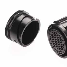
Caps for Connectors:
Standard Caps: Chain and lugs in stainless steel
S Caps: Stainless steel wire rope, polyamide black covered
W Caps: with textile black rope (white on request)
TL Caps: Stainless steel wire rope, polyamide black covered. Supplied with loose terminal link and crimp sleeve
373 Go online for data sheets & assembly instructions. Visit www.radiall.com/vansystem and enter the part number. ACCESSORIES
CV..043
CV..042
Caps for Bayonet Connectors
Caps with chain for connectors version: shell type with ramp Provided with sealing gasket. Chain and lugs are in stainless steel. Protection degree: IP 67 (mated to the connector) according to EN 60529.
10SL VS151101
14S VS151102
043-10SL F7
043-14S F7 16S VS151103 CVB 043-16S F7 16 VS151104
043-16 F7 18 VS151105 CVB 043-18 F7 20 VS151106 CVB 043-20 F7 22 VS151107 CVB 043-22 F7
VS151108 CVB 043-24 F7
F7
F7
VS151111
VS151112
043-40 F7 GVJ On Request GVJ 043 F7 Shell size Part Number Short Description
043-36 F7
Shell
10SL VS151125 CVB 043-10SL F16
14S VS151126 CVB 043-14S F16
16S VS151127 CVB 043-16S F16
16 VS151128 CVB 043-16 F16
18 VS151129 CVB 043-18 F16
20 VS151130 CVB 043-20 F16
22 VS151131 CVB 043-22 F16
VS151132 CVB 043-24 F16 28 VS151133 CVB 043-28 F16 32 VS151134 CVB 043-32 F16 36 VS151135 CVB 043-36 F16
043-40 F16
043 F16
VS151113 CVB 043-10SL F4
VS151114 CVB 043-14S F4
VS151115
043-16S F4
F4
VS151117 CVB 043-18 F4
20 VS151118 CVB 043-20 F4
22 VS151119 CVB 043-22 F4
24 VS151120 CVB 043-24 F4
28 VS151121 CVB 043-28 F4
32 VS151122 CVB 043-32 F4
36 VS151123 CVB 043-36 F4
40 VS151124 CVB 043-40 F4 Dimensions
374 Go online for data sheets &
instructions. Visit www.radiall.com/vansystem and enter the part number. ACCESSORIES L ØQ F ØT F ØQ L
L min L min
assembly
ØT
Number Short
Shell size Part
Description
CVB
32
36
10SL
16S
CVB
CVB
24
28 VS151109 CVB 043-28
VS151110 CVB 043-32
CVB
40
CVB
14S
CVB
16 VS151116 CVB 043-16
18
in mm
size Part Number Short Description
40
CVB
GVJ
GVJ
Shell size Part Number Short Description 10SL
14S
16S VS151139 CVB
16 VS151140 CVB 043-16
18 VS151141 CVB 043-18
20 VS151142 CVB 043-20 F5 22 VS151143 CVB 043-22 F5 24 VS151144 CVB 043-24 F5 28 VS151145 CVB 043-28 F5 32 VS151146 CVB 043-32 F5 36 VS151147 CVB 043-36 F5 40 VS151148 CVB 043-40 F5 Finishes : F7 Black epoxy varnish (RoHS compliance) Finishes : F4 CCF - Green passivation - conductive Finishes : F16 CCF - Black passivation (RoHS compliance) - conductive Finishes : F5 Electroless nickel (RoHS compliance) Shell size ØQ F L min ØT 10SL 23.6 16 108 4.3 14S 30 16 108 4.3 16S 33 16 108 4.3 16 33.6 20.9 123 4.3 18 38 21.7 123 4.3 20 40.5 21.7 123 4.3 22 44 21.7 123 4.3 24 47 21.7 123 4.3 28 53 21.7 206 4.3 32 60 21.7 206 4.3 36 66.2 21.7 206 4.3 40 72.4 21.7 206 4.3 GVJ 96 28.2 285 8.4
24
VS151136
On Request
VS151137 CVB 043-10SL F5
VS151138 CVB 043-14S F5
043-16S F5
F5
F5
CVB-CVBS-CVBSG-CVBR-GVJ - Accessories For Connectors
Caps for Bayonet Connectors
CVB-CVBS-CVBSG-CVBR-GVJ - Accessories For
Connectors
Caps with chain for connector version: shell type with coupling nut
These caps have no sealing gasket because mated with connectors generally provided with front gasket. Chain and lugs are in stainless steel. Protection degree: IP 67 (mated to the connector) according to EN 60529.
Shell size Part Number Short Description
10SL VS151201
14S VS151202
CVB 042-10SL F7
CVB 042-14S F7
16S VS151203 CVB 042-16S F7
16 VS151204 CVB 042-16 F7
18 VS151205 CVB 042-18 F7
20 VS151206 CVB 042-20 F7
22 VS151207 CVB 042-22 F7
24 VS151208 CVB 042-24 F7
28 VS151209 CVB 042-28 F7
32 VS151210 CVB 042-32 F7
36 VS151211 CVB 042-36 F7
40 VS151212 CVB 042-40 F7 GVJ On Request GVJ 04 F7
Shell size Part Number
10SL VS151225
Short Description
CVB 042-10SL F16
14S VS151226 CVB 042-14S F16
16S VS151227 CVB 042-16S F16
16 VS151228 CVB 042-16 F16
18 VS151229 CVB 042-18 F16
20 VS151230 CVB 042-20 F16
22 VS151231 CVB 042-22 F16
24 VS151232 CVB 042-24 F16
28 VS151233 CVB 042-28 F16
32 VS151234 CVB 042-32 F16
36 VS151235 CVB 042-36 F16
40 VS151236 CVB 042-40 F16
GVJ On Request GVJ 042 F7
Shell size Part Number
10SL VS151213
Short Description
CVB 042-10SL F4
14S VS151214 CVB 042-14S F4
16S VS151215 CVB 042-16S F4
16 VS151216 CVB 042-16 F4
18 VS151217 CVB 042-18 F4
20 VS151218 CVB 042-20 F4
22 VS151219 CVB 042-22 F4
24 VS151220 CVB 042-24 F4
28 VS151221 CVB 042-28 F4
32 VS151222 CVB 042-32 F4
36 VS151223 CVB 042-36 F4
40 VS151224 CVB 042-40 F4
Shell size Part Number Short Description
10SL VS151237 CVB 042-10SL F5
14S VS151238 CVB 042-14S F5
16S VS151239 CVB 042-16S F5
16 VS151240 CVB 042-16 F5
18 VS151241 CVB 042-18 F5
20 VS151242 CVB 042-20 F5 22 VS151243 CVB 042-22 F5
VS151244 CVB 042-24 F5 28 VS151245 CVB 042-28 F5
32 VS151246 CVB 042-32 F5
36 VS151247 CVB 042-36 F5
40 VS151248 CVB 042-40 F5
375 Go online
Visit www.radiall.com/vansystem and enter the part number. ACCESSORIES L ØQ F ØT F ØQ L ØT min min
for data sheets & assembly instructions.
Dimensions in mm Finishes : F7 Black epoxy varnish (RoHS compliance) Finishes : F4 CCF - Green passivation - conductive Finishes : F16 CCF - Black passivation (RoHS compliance) - conductive Finishes : F5 Electroless nickel (RoHS compliance) Shell size ØQ F L min ØT 10SL 20.6 27.3 108 4.3 14S 27 27.3 123 4.3 16S 29.8 27.3 123 4.3 16 29.8 34.5 123 4.3 18 33 34.5 123 4.3 20 36.5 34.5 138 4.3 22 39.7 34.5 138 4.3 24 43.2 34.5 138 4.3 28 48.9 34.5 206 4.3 32 55.5 34.5 206 4.3 36 61.6 34.5 206 4.3 40 67.6 34.5 206 4.3 GVJ 93 60 285 8.4
24
Caps for Threaded Connectors
Caps with chain for connectors version: shell type with threaded Provided with sealing gasket. Chain and lugs are in stainless steel. Protection degree: IP 67 (mated to the connector) according to EN 60529.
CVS 043-14S F4
CVS 043-16S F4
CVS 043-16 F4
VS150117 CVS 043-18 F4
VS150118 CVS 043-20 F4
VS150119 CVS 043-22 F4
VS150120 CVS 043-24 F4
VS150121 CVS 043-28 F4 32 VS150122 CVS 043-32 F4 36 VS150123 CVS 043-36 F4 40 VS150124 CVS 043-40 F4 Shell size
: F16 CCF - Black passivation (RoHS compliance) - conductive
10SL VS150125 CVS 043-10SL F16
14S VS150126 CVS 043-14S F16
16S VS150127 CVS 043-16S F16 16 VS150128 CVS 043-16 F16 18 VS150129 CVS 043-18 F16 20 VS150130 CVS 043-20 F16
VS150131 CVS 043-22 F16 24
376 Go online for data sheets
Visit www.radiall.com/vansystem
enter the part number. ACCESSORIES
& assembly instructions.
and
L min ØQ F ØT D L min F D ØQ ØT Dimensions in mm
Finishes
CCF - Green passivation - conductive
Finishes
Shell size D Thread in inches ØQ F L min ØT 10SL 5/8”-24 UNEF 24 13.1 108 4.3 14S 7/8”-20 UNEF 29 13.1 108 4.3 16S 1”-20 UNEF 30.5 13.1 108 4.3 16 1”-20 UNEF 30.5 13.1 123 4.3 18 1”1/8-18 UNEF 34 13.1 123 4.3 20 1”1/4-18 UNEF 37 13.1 123 4.3 22 1”3/8-18 UNEF 41 13.1 123 4.3 24 1”1/2-18 UNEF 43 13.1 123 4.3 28 1”3/4-18 UNEF 50 13.1 206 4.3 32 2”-18 UNS 56 14.7 206 4.3 36 2”1/4-16 UN 61 14.7 206 4.3 40 2”1/2-16 UN 69 14.7 206 4.3
Short
10SL VS150101 CVS 043-10SL F7 14S VS150102 CVS 043-14S
16S VS150103 CVS 043-16S
16 VS150104 CVS 043-16
18
CVS 043-18
20 VS150106 CVS 043-20
22 VS150107 CVS 043-22 F7 24 VS150108 CVS 043-24 F7 28 VS150109 CVS 043-28
32 VS150110 CVS 043-32
36 VS150111 CVS 043-36
40 VS150112 CVS 043-40
Shell size Part Number Short Description 10SL VS150113
14S
16S
16 VS150116
18
20
Part Number Short Description
Finishes : F7 Black epoxy varnish (RoHS compliance)
: F4
Finishes
: F5 Electroless nickel (RoHS compliance)
Shell size Part Number
Description
F7
F7
F7
VS150105
F7
F7
F7
F7
F7
F7
CVS 043-10SL F4
VS150114
VS150115
22
24
28
VS150132 CVS 043-24 F16 28 VS150133 CVS 043-28 F16 32 VS150134 CVS 043-32 F16 36 VS150135 CVS 043-36 F16 40 VS150136 CVS 043-40 F16 Shell size Part Number Short Description 10SL VS150137 CVS 043-10SL F5 14S VS150138 CVS 043-14S
16S VS150139 CVS 043-16S
16 VS150140 CVS 043-16
18 VS150141 CVS 043-18
20 VS150142 CVS 043-20
22 VS150143 CVS 043-22
24 VS150144 CVS 043-24
28 VS150145 CVS 043-28
32 VS150146 CVS 043-32
36 VS150147 CVS 043-36
40 VS150148 CVS
22
F5
F5
F5
F5
F5
F5
F5
F5
F5
F5
043-40 F5 CVS - Accessories For Connectors
Caps for Threaded Connectors
CVS - Accessories For Connectors
Caps with chain for connector version: shell type with coupling nut
These caps have no sealing gasket because mated with connectors generally provided with front gasket. Chain and lugs are in stainless steel. Protection degree: IP 67 (mated to the connector) according to EN 60529.
Finishes : F7 Black epoxy varnish
Shell size Part Number Short Description
10SL VS150201 CVS 042-10SL F7
14S VS150202 CVS 042-14S F7
16S VS150203 CVS 042-16S F7
16 VS150204 CVS 042-16 F7
18 VS150205 CVS 042-18 F7
20 VS150206 CVS 042-20 F7
22 VS150207 CVS 042-22 F7
24 VS150208 CVS 042-24 F7
28 VS150209 CVS 042-28 F7
32 VS150210 CVS 042-32 F7
36 VS150211 CVS 042-36 F7
40 VS150212 CVS 042-40 F7
Shell size Part Number
Short Description
10SL VS150225 CVS 042-10SL F16
14S VS150226 CVS 042-14S F16
16S VS150227 CVS 042-16S F16
16 VS150228 CVS 042-16 F16
18 VS150229 CVS 042-18 F16
VS150230 CVS 042-20 F16
VS150231 CVS 042-22 F16
VS150232 CVS 042-24 F16
VS150233 CVS 042-28 F16
VS150234 CVS 042-32 F16
VS150235 CVS 042-36 F16
VS150236 CVS 042-40 F16
Go online for data sheets & assembly instructions.
Shell size Part Number Short Description
10SL VS150213 CVS 042-10SL F4
14S VS150214 CVS 042-14S F4
16S VS150215 CVS 042-16S F4
16 VS150216 CVS 042-16 F4
18 VS150217 CVS 042-18 F4
20 VS150218 CVS 042-20 F4
22 VS150219 CVS 042-22 F4
24 VS150220 CVS 042-24 F4
28 VS150221 CVS 042-28 F4
32 VS150222 CVS 042-32 F4
36 VS150223 CVS 042-36 F4
40 VS150224 CVS 042-40 F4
Shell size Part Number
Description
VS150237 CVS 042-10SL F5 14S VS150238 CVS 042-14S F5
VS150239 CVS 042-16S F5
VS150240 CVS 042-16 F5
VS150241 CVS 042-18 F5
VS150242 CVS 042-20 F5
VS150243 CVS 042-22 F5
VS150244 CVS 042-24 F5
VS150245 CVS 042-28 F5
VS150246 CVS 042-32 F5
VS150247 CVS 042-36 F5
VS150248 CVS 042-40 F5
377
Visit www.radiall.com/vansystem and enter the part number. ACCESSORIES
L min F D ØQ ØT Dimensions in mm Shell size D Thread in inches ØQ F L min ØT 10SL 5/8”-24 UNEF 18 16.5 108 4.3 14S 7/8”-20 UNEF 24 16.5 123 4.3 16S 1”-20 UNEF 27 16.5 123 4.3 16 1”-20 UNEF 27 21.4 123 4.3 18 1”1/8-18 UNEF 30 21.4 123 4.3 20 1”1/4-18 UNEF 34 21.4 138 4.3 22 1”3/8-18 UNEF 37 21.4 138 4.3 24 1”1/2-18 UNEF 40 21.4 138 4.3 28 1”3/4-18 UNEF 46 21.4 206 4.3 32 2”-18 UNS 52.5 22.5 206 4.3 36 2”1/4-16 UN 59 22.5 206 4.3 40 2”1/2-16 UN 65 22.5 206 4.3
conductive Finishes
(RoHS compliance) Finishes : F4 CCF - Green passivation - conductive Finishes : F16 CCF - Black passivation (RoHS compliance) -
: F5 Electroless nickel (RoHS compliance)
20
22
24
28
32
36
40
16
18
20
22
24
28
32
36
40
Short
10SL
16S
Protective Plastic Dust Caps
Accessories For Connectors
These caps are used to protect connectors against dust. They are not included in the connectors and have to be ordered separately. The drawings are indicative only and they could be change according to the size
Caps for connectors version: shell type with ramp
Caps for connector version: shell type with coupling nut
Caps for connector version: shell type with rubber covered coupling nut
PCVBSG 042-10
PCVBSG 042-14
PCVBSG 042-16
PCVBSG 042-18
PCVBSG 042-20
PCVBSG 042-22
PCVBSG 042-24
PCVBSG 042-28
PCVBSG 042-32
PCVBSG 042-36
PCVBSG 042-40
PGVJ 042
378 Go online for data sheets & assembly instructions. Visit www.radiall.com/vansystem and enter the part number. ACCESSORIES
Shell size Part Number Short Description 10SL VS412110 PCVB 043-10 10SL
only) VS412111 PCVS
14S VS412112
16/16S VS412113 PCV 043-16 18 VS412114 PCV 043-18 20 VS412115 PCV 043-20 22 VS412116 PCV 043-22 24 VS412117 PCV 043-24 28 VS412118 PCV 043-28 32 VS412119 PCV 043-32 36 VS412120 PCV 043-36 40 VS412121 PCV 043-40 GVJ VS412122 PGVJ
Shell size Part Number Short Description 10SL VS412123 PCVB 042-10 10SL (CVS version only) VS412124 PCVS 042-10 14S VS412125 PCV 042-14 16/16S VS412126 PCV 042-16 18 VS412127 PCV 042-18 20 VS412128 PCV 042-20 22 VS412129 PCV 042-22 24 VS412130 PCV 042-24 28 VS412148
32 VS412144
36 VS412145 PCV
40 VS412146
(CVS version
043-10
PCV 043-14
043
PCV 042-28
PCV 042-32
042-36
PCV 042-40
size Part Number Short Description 10SL VS412156
14S VS412157
16S VS412158
18 VS412159
20 VS412160
22 VS412161
24 VS412162
28 VS412163
32 VS412164
36 VS412165
40
GVJ
Shell
VS412166
VS412147
Connector Closure Plate
CVS-CVB-CVBS-CVBSG-CVBR - Accessories For Connectors
Connector Closur Plate in stainless steel alloy provided with chloroprene rubber Gasket
Plate and Gaskets for mounting panel connectors
379 Go online for data sheets & assembly instructions. Visit www.radiall.com/vansystem and enter the part number. ACCESSORIES
Shell size Part Number Non conductive Short Description Non conductive A ±0.1 B ±0.2 S ØT 10SL VS412521 C026-10 18.2 18.2 3 3.1 14S VS412520 C026-14 23 23 3 3.1 16S/16 VS412519 C026-16 24.6 24.6 4 3.1 18 VS412518 C026-18 27 27 4 3.1 20 VS412517 C026-20 29.4 29.4 4 3.1 22 VS412516 C026-22 31.8 31.8 4 3.1 24 VS412515 C026-24 34.9 34.9 4 3.7 28 VS412514 C026-28 39.7 39.7 4 3.7 32 VS412513 C026-32 44.5 44.5 4 4.4 36 VS412512 C026-36 49.2 49.2 4 4.4 40 VS412511 C026-40 55.6 55.6 4 4.4 Dimensions in mm
1 ØT A B S
Connector Mounting Gaskets
CVS-CVB-CVBS-CVBSG-CVBR - Accessories For Connectors
These gaskets are used to make panel connectors water resistant.
Gaskets for front mounting panel connectors (00 - 020 - 02 - 05 connectors):
• gasket C215: non conductive chloroprene rubber gasket (IP67 protection)
• gasket C215R: conductive chloroprene rubber gasket with embedded metal screen (IP65 protection).
These gaskets guarantee watertightness and RFI shielding
Gaskets for rear mounting panel connectors (03 - 030 - 038 connectors):
• gasket C216: non conductive chloroprene rubber gasket (IP67 protection)
• gasket C216R: conductive chloroprene rubber gasket with embedded metal screen (IP65 protection).
These gaskets guarantee watertightness and RFI shielding
On request: RF flame resistant gasket, (V) Fluoride rubber or (S) silicone gaskets.
These gaskets are not needed by GVJ connectors.
380 Go online for data sheets & assembly instructions. Visit www.radiall.com/vansystem and enter the part number. ACCESSORIES s ØT ØC A B s ØT ØC A B 2
Shell size Part Number Non conductive Short Description Non conductive Part Number Conductive Short Description Conductive A ±0.2 B -0 +0.4 ØC ±0.3 S C215 S2 C215R ØT ±0.3 10SL VS412301 C215-10 VS412351 C215R-10 18.2 25.4 16.3 1±0.3 0.5±0.2 4.3 14S VS412302 C215-14 VS412352 C215R-14 23 30.2 22.2 1±0.3 0.5±0.2 4.3 16S/16 VS412303 C215-16 VS412353 C215R-16 24.6 32.5 25.4 1±0.3 0.5±0.2 4.3 18 VS412304 C215-18 VS412354 C215R-18 27 35 28.6 1±0.3 0.5±0.2 5.1 20 VS412305 C215-20 VS412355 C215R-20 29.4 38.1 31.8 1±0.3 0.5±0.2 5.1 22 VS412306 C215-22 VS412356 C215R-22 31.8 41.2 34.9 1±0.3 0.5±0.2 5.1 24 VS412307 C215-24 VS412357 C215R-24 34.9 44.5 38.1 1±0.3 0.5±0.2 5.1 28 VS412308 C215-28 VS412358 C215R-28 39.7 50.8 44.5 1±0.3 0.5±0.2 5.1 32 VS412309 C215-32 VS412359 C215R-32 44.5 57 50.8 1±0.3 0.5±0.2 5.5 36 VS412314 C215-36 VS412360 C215R-36 49.2 63.5 55.6 1±0.3 0.5±0.2 5.5 40 VS412315 C215-40 VS412361 C215R-40 55.5 69.9 61.9 1±0.3 0.5±0.2 5.5 Dimensions in mm Shell size Part Number Non conductive Short Description Non conductive Part Number Conductive Short Description Conductive A ±0.2 B -0 +0.4 ØC ±0.3 S C216 S2 C216R ØT ±0.3 10SL VS412401 C216-10 VS412451 C216R-10 18.2 25.4 18.2 0.8±0.3 0.5±0.2 4.2 14S VS412402 C216-14 VS412452 C216R-14 23 30.2 24.6 0.8±0.3 0.5±0.2 4.2 16S/16 VS412403 C216-16 VS412453 C216R-16 24.6 32.5 27.4 0.8±0.3 0.5±0.2 4.2 18 VS412404 C216-18 VS412454 C216R-18 27 35 30.8 0.8±0.3 0.5±0.2 4.2 20 VS412405 C216-20 VS412455 C216R-20 29.4 38.1 34.2 0.8±0.3 0.5±0.2 4.2 22 VS412406 C216-22 VS412456 C216R-22 31.8 41.2 37.4 0.8±0.3 0.5±0.2 4.2 24 VS412407 C216-24 VS412457 C216R-24 34.9 44.5 40.9 0.8±0.3 0.5±0.2 4.2 28 VS412408 C216-28 VS412458 C216R-28 39.7 50.8 46.7 0.8±0.3 0.5±0.2 5.1 32 VS412409 C216-32 VS412459 C216R-32 44.5 57 53.4 0.8±0.3 0.5±0.2 5.1 36 VS412410 C216-36 VS412460 C216R-36 49.2 63.5 59.6 0.8±0.3 0.5±0.2 5.1 40 VS412411 C216-40 VS412461 C216R-40 55.5 69.9 65.5 0.8±0.3 0.5±0.2 5.1
G3 Shielded Gaskets
CVS-CVB-CVBS-CVBSG-CVBR - Accessories For Connectors
Gaskets C215G3 and C216G3: conductive silicone gaskets with embedded metal screen. These gaskets guarantee watertightness and RFI shielding
• Elastomer binder: Silicone
• Conductive filler: Nickel Graphite
• Color: Gray
• Operating Temperature range: -60 °C ÷ +220 °C
• Flammability Rating: UL 94-V0
• Salt spray test > 96 h ( consult our sales office for details)
• IP67 protection (EN 60529)
C215 Gaskets for front mounting panel connectors (00 - 020 - 02 connectors):
C216 Gaskets for rear mounting panel connectors (03 - 030 - 038 connectors):
381 Go online for data sheets & assembly
Visit www.radiall.com/vansystem and enter the part number. ACCESSORIES s ØT ØC A B ØT
instructions.
Shell size Part Number Conductive Short Description Conductive A ±0.2 B -0 +0.4 ØC ±0.3 S C215G3 ØT ±0.3
VS412331 C215G3-10 18.2 25.4 16.3 0.8±0.2 4.3 14S VS412332 C215G3-14 23 30.2 22.2 0.8±0.2 4.3 16S/16 VS412333 C215G3-16 24.6 32.5 25.4 0.8±0.2 4.3 18 VS412334 C215G3-18 27 35 28.6 0.8±0.2 5.1 20 VS412335 C215G3-20 29.4 38.1 31.8 0.8±0.2 5.1 22 VS412336 C215G3-22 31.8 41.2 34.9 0.8±0.2 5.1 24 VS412337 C215G3-24 34.9 44.5 38.1 0.8±0.2 5.1 28 VS412338 C215G3-28 39.7 50.8 44.5 0.8±0.2 5.1 32 VS412339 C215G3-32 44.5 57 50.8 0.8±0.2 5.5 36 VS412340 C215G3-36 49.2 63.5 55.6 0.8±0.2 5.5 40 VS412341 C215G3-40 55.5 69.9 61.9 0.8±0.2 5.5 Dimensions in mm Shell size Part Number Conductive Short Description Conductive A ±0.2 B -0 +0.4 ØC ±0.3 S C216G3 ØT ±0.3 10SL VS412431 C216G3-10 18.2 25.4 18.2 0.8±0.2 4.2 14S VS412432 C216G3-14 23 30.2 24.6 0.8±0.2 4.2 16S/16 VS412433 C216G3-16 24.6 32.5 27.4 0.8±0.2 4.2 18 VS412434 C216G3-18 27 35 30.8 0.8±0.2 4.2 20 VS412435 C216G3-20 29.4 38.1 34.2 0.8±0.2 4.2 22 VS412436 C216G3-22 31.8 41.2 37.4 0.8±0.2 4.2 24 VS412437 C216G3-24 34.9 44.5 40.9 0.8±0.2 4.2 28 VS412438 C216G3-28 39.7 50.8 46.7 0.8±0.2 5.1 32 VS412439 C216G3-32 44.5 57 53.4 0.8±0.2 5.1 36 VS412440 C216G3-36 49.2 63.5 59.6 0.8±0.2 5.1 40 VS412441 C216G3-40 55.5 69.9 65.5 0.8±0.2 5.1
10SL
Cable-Clamps A type
CVS-CVB-CVBS-CVBSG-CVBR - Accessories For Connectors
MS 3057 - ...A Cable-Clamps, general duty
These Cable-Clamps keep the cable in the connector axial position and guarantee an excellent mechanical strain relief. MS 3420 or RF 3420 Bushing are not waterproof and are generally supplied separately except for classes AF,F,LAF and LF connectors.
Finishes : F7 Black epoxy varnish (RoHS compliance)
Finishes : F4 CCF - Green passivation - conductive
Finishes : F16 CCF - Black passivation (RoHS compliance) - conductive
Finishes : F5 Electroless nickel (RoHS compliance)
382 Go online for data sheets & assembly instructions. Visit www.radiall.com/vansystem and enter the part number. ACCESSORIES Y A V N N A Y ØF N A Y ØF ØF
Dimensions in mm Shell size Part Number Short Description Y max V ±0.2 A max ØF max cable Ø N Thread in inches 10SL VS705201 MS 3057-4A F7 20.6 10.5 22.5 8 5/8”-24 UNEF 14S VS705202 MS 3057-6A F7 22.2 10.5 28 11 3/4”-20 UNEF 16S -16 VS705203 MS 3057-8A F7 25 10.5 30 14.2 7/8”-20 UNEF 18 VS705204 MS 3057-10A F7 25 10.5 31.7 15.8 1”-20 UNEF 20 - 22 VS705205 MS 3057-12A F7 25 10.5 37.5 19 1” 3/16-18 UNEF 24 - 28 VS705206 MS 3057-16A F7 26 10.5 43.5 23.8 1” 7/16-18 UNEF 32 VS705207 MS 3057-20A F7 28 12.5 51.7 31.7 1” 3/4-18 UNS 36 VS705208 MS 3057-24A F7 29.4 14 58.5 35 2”-18 UNS 40 VS705209 MS 3057-28A F7 42.8 14 68.5 41.2 2”1/4-16 UN Shell size Part Number Short Description Y max V ±0.2 A max ØF max cable Ø N Thread in inches 10SL VS705211 MS 3057-4A F4 20.6 10.5 22.5 8 5/8”-24 UNEF 14S VS705212 MS 3057-6A F4 22.2 10.5 28 11 3/4”-20 UNEF 16S -16 VS705213 MS 3057-8A F4 25 10.5 30 14.2 7/8”-20 UNEF 18 VS705214 MS 3057-10A F4 25 10.5 31.7 15.8 1”-20 UNEF 20 - 22 VS705215 MS 3057-12A F4 25 10.5 37.5 19 1” 3/16-18 UNEF 24 - 28 VS705216 MS 3057-16A F4 26 10.5 43.5 23.8 1” 7/16-18 UNEF 32 VS705217 MS 3057-20A F4 28 12.5 51.7 31.7 1” 3/4-18 UNS 36 VS705218 MS 3057-24A F4 29.4 14 58.5 35 2”-18 UNS 40 VS705219 MS 3057-28A F4 42.8 14 68.5 41.2 2”1/4-16 UN
Shell size Part Number Short Description Y max V ±0.2 A max ØF max cable Ø N Thread in inches 10SL VS705221 MS 3057-4A F16 20.6 10.5 22.5 8 5/8”-24 UNEF 14S VS705222 MS 3057-6A F16 22.2 10.5 28 11 3/4”-20 UNEF 16S -16 VS705223 MS 3057-8A F16 25 10.5 30 14.2 7/8”-20 UNEF 18 VS705224 MS 3057-10A F16 25 10.5 31.7 15.8 1”-20 UNEF 20 - 22 VS705225 MS 3057-12A F16 25 10.5 37.5 19 1” 3/16-18 UNEF 24 - 28 VS705226 MS 3057-16A F16 26 10.5 43.5 23.8 1” 7/16-18 UNEF 32 VS705227 MS 3057-20A F16 28 12.5 51.7 31.7 1” 3/4-18 UNS 36 VS705228 MS 3057-24A F16 29.4 14 58.5 35 2”-18 UNS 40 VS705229 MS 3057-28A F16 42.8 14 68.5 41.2 2”1/4-16 UN Shell size Part Number Short Description Y max V ±0.2 A max ØF max cable Ø N Thread in inches 10SL VS705231 MS 3057-4A F5 20.6 10.5 22.5 8 5/8”-24 UNEF 14S VS705232 MS 3057-6A F5 22.2 10.5 28 11 3/4”-20 UNEF 16S -16 VS705233 MS 3057-8A F5 25 10.5 30 14.2 7/8”-20 UNEF 18 VS705234 MS 3057-10A F5 25 10.5 31.7 15.8 1”-20 UNEF 20 - 22 VS705235 MS 3057-12A F5 25 10.5 37.5 19 1” 3/16-18 UNEF 24 - 28 VS705236 MS 3057-16A F5 26 10.5 43.5 23.8 1” 7/16-18 UNEF 32 VS705237 MS 3057-20A F5 28 12.5 51.7 31.7 1” 3/4-18 UNS 36 VS705238 MS 3057-24A F5 29.4 14 58.5 35 2”-18 UNS 40 VS705239 MS 3057-28A F5 42.8 14 68.5 41.2 2”1/4-16 UN
Bushing
for Cable-Clamps A type
MS 3420 - … - RF 3420 - … Bushing
They are made of elastomeric rubber and used with Cable-Clamps MS3057 - ...A to protect the cable.
In the same Cable-Clamps it is possible to assemble more than one bushing (inside each other) so to achieve diameters much smaller than the nominal.
Available in two versions:
• MS 3420 - … in neoprene rubber.
• RF 3420 - … in flame resistant rubber.
383
Visit www.radiall.com/vansystem and enter the part number. ACCESSORIES L L ØF ØC ØA S ØF ØC
Go online for data sheets & assembly instructions.
Shell size Part Number Short Description For Cable gland ØA ±0.4 ØF ±0.4 ØC ±0.4 S ±0.4 L ±0.4 10SL VS705401 MS 3420-4 MS 3057-4A 12.8 5.6 7.6 1.6 69.8 14S VS705402 MS 3420-6 MS 3057-6A 15.7 7.9 10.8 1.6 66.8 16S -16 VS705403 MS 3420-8 MS 3057-8A 18.8 11 14 1.6 63.5 18 VS705404 MS 3420-10 MS 3057-10A 22 14.2 15.6 1.6 60.3 20 - 22 VS705405 MS 3420-12 MS 3057-12A 27 15.8 18.8 1.6 57.1 24 - 28 VS705406 MS 3420-16 MS 3057-16A 33.3 19 23.6 1.6 53.9 32 VS705407 MS 3420-20 MS 3057-20A 40.5 23.8 31.5 1.6 50.8 36 VS705408 MS 3420-24 MS 3057-24A 46.9 31.7 34.8 1.6 47.6 40 VS705409 MS 3420-28 MS 3057-28A 52.9 34.9 41 1.6 44.4 On request: V = Fluoride Rubber S = Silicone Rubber Dimensions in mm Neoprene rubber
CVS-CVB-CVBS-CVBSG-CVBR - Accessories For Connectors Shell size Part Number Short Description For Cable gland ØA ±0.4 ØF ±0.4 ØC ±0.4 S ±0.4 L ±0.4 14S VS705412 RF 3420-6 MS 3057-6A 15.7 7.9 10.8 1.6 66.8 16S -16 VS705413 RF 3420-8 MS 3057-8A 18.8 11 14 1.6 63.5 18 VS705414 RF 3420-10 MS 3057-10A 22 14.2 15.6 1.6 60.3 20 - 22 VS705415 RF 3420-12 MS 3057-12A 27 15.8 18.8 1.6 57.1 24 - 28 VS705416 RF 3420-16 MS 3057-16A 33.3 19 23.6 1.6 53.9 32 VS705417 RF 3420-20 MS 3057-20A 40.5 23.8 31.5 1.6 50.8 36 VS705418 RF 3420-24 MS 3057-24A 46.9 31.7 34.8 1.6 47.6 40 VS705419 RF 3420-28 MS 3057-28A 52.9 34.9 41 1.6 44.4
Flame resistant rubber
Cable-Clamps C type
CVS-CVB-CVBS-CVBSG-CVBR
MS 3057 - ...C - RF 3057 - ...C water tight Cable-Clamps
Besides guaranteeing an excellent mechanical strain relief keeping the cable in the centre of the connector, these Cable-Clamps are provided with an internal conical rubber bushing ensuring waterproof protection. The screws in stainless steel have elastic rose-cut antivibration head.
Available in two versions:
• MS 3057 - …C with gasket in neoprene rubber.
Finishes : F7 Black epoxy varnish (RoHS compliance)
- GVJ
Finishes : F4 CCF - Green passivation - conductive
14S VS705262
16S -16 VS705263
18 VS705264
32 VS705267
36 VS705268
40 VS705269
F7
F7
F7
F4
MS 3057-6C F4
MS 3057-8C F4
MS 3057-10C F4
F4
MS 3057-20C F4
MS 3057-24C F4
MS 3057-28C F4
Finishes : F16 CCF - Black passivation (RoHS compliance) - conductive
16S -16
F4
F4
F4
F4
RF 3057-16C F4
F4
3057-24C F4
F16 14S VS705272 MS 3057-6C F16
3057-8C F16
F16
F16
F16
F16
3057-6C F16
3057-8C F16
F16
F16
F16 36 VS705278
Finishes : F5 Electroless nickel (RoHS compliance) Shell
• RF 3057 - …C with gasket in flame resistant rubber. Gasket on request: V = Fluoride Rubber - S = Silicone Rubber
3057-24C F16
F16 40 - GVJ
384 Go online for data sheets & assembly instructions. Visit www.radiall.com/vansystem and enter the part number. ACCESSORIES Y A V N N A Y ØF N A Y ØF ØF
Dimensions
size Part Number
Short Description neoprene
Part Number flame resistant rubber Short Description flame resistant rubber 10SL VS705251 MS 3057-4C F7 VS705301 RF 3057-4C F7 14S VS705252 MS 3057-6C F7 VS705302 RF 3057-6C F7 16S -16 VS705253 MS 3057-8C F7 VS705303 RF 3057-8C F7 18 VS705254 MS 3057-10C
VS705304 RF 3057-10C
20 - 22 VS705255 MS 3057-12C
VS705305 RF 3057-12C F7 24 - 28 VS705256 MS 3057-16C F7 VS705306 RF 3057-16C F7 32 VS705257 MS 3057-20C
VS705307 RF 3057-20C
36 VS705258 MS 3057-24C
VS705308 RF 3057-24C
40
VS705259 MS 3057-28C
VS705309 RF 3057-28C
in mm Shell
neoprene rubber
rubber
F7
F7
F7
F7
F7
F7
size Part Number neoprene
Short Description neoprene rubber Part Number flame resistant rubber Short Description flame resistant rubber
VS705311 RF
rubber
10SL VS705261 MS 3057-4C
3057-4C
VS705312 RF
3057-6C
VS705313 RF
3057-8C
VS705314 RF 3057-10C
20
VS705265 MS 3057-12C
VS705315 RF 3057-12C
24
VS705266 MS 3057-16C
VS705316
- 22
F4
F4
- 28
VS705317
RF 3057-20C
VS705318
RF
VS705319 RF 3057-28C
Shell size Part Number neoprene rubber Short Description neoprene rubber Part Number flame resistant rubber Short Description flame resistant rubber 10SL VS705271 MS 3057-4C
VS705321 RF 3057-4C
VS705322 RF
F4
F16
VS705273
VS705323 RF
MS
3057-10C
VS705324 RF 3057-10C
22 VS705275 MS 3057-12C
VS705325 RF 3057-12C
24
28 VS705276 MS 3057-16C
VS705326 RF
VS705327 RF
VS705328 RF
VS705279 MS 3057-28C F16 VS705329 RF 3057-28C F16 Shell size Part Number neoprene rubber Short Description neoprene rubber 10SL VS705281 MS 3057-4C F5 14S VS705282 MS 3057-6C F5 16S -16 VS705283 MS 3057-8C F5 18 VS705284 MS 3057-10C F5 20 - 22 VS705285 MS 3057-12C F5 24 - 28 VS705286 MS 3057-16C F5 32 VS705287 MS 3057-20C F5 36 VS705288 MS 3057-24C F5 40 VS705289 MS 3057-28C F5 IP67 Type Shell size Y max A max ØF cable min max N Thread in inches 4C 10SL 33.4 23 2.4 7.9 5/8”-24 UNEF 6C 14S 32.3 26 5.8 11.2 3/4”-20 UNEF 8C 16S -16 32.3 28.5 8 13.5 7/8”-20 UNEF 10C 18 35 32 9.6 15.9 1”-20 UNEF 12C 20 - 22 35.7 37.5 11.3 19 1” 3/16-18 UNEF 16C 24 - 28 39 43.5 15.5 23.8 1” 7/16-18 UNEF 20C 32 44.8 54 23.4 31.8 1” 3/4-18 UNS 24C 36 52 58 25.4 35 2”-18 UNS 28C 40 - GVJ 52.3 63.5 30 41.3 2”1/4-16 UN
18 VS705274 MS
F16 20 -
-
3057-16C
32 VS705277 MS 3057-20C
3057-20C
MS
3057-24C
- GVJ - Accessories For Connectors
Bushing for Cable-Clamps C type
CVS-CVB-CVBS-CVBSG-CVBR - GVJ - Accessories For Connectors
MS 3420 - ...A - RF 3420 - ...A Bushing
They are made of elastomeric rubber and used with Cable-Clamps MS 3057 - ...C to protect the cable. They allow using cables with diameter smaller than the nominal.
Available in two versions:
• MS 3420 - …A in neoprene rubber.
• RF 3420 - …A in flame resistant rubber (on request).
rubber
On request: V = Fluoride
385 Go online
data
Visit www.radiall.com/vansystem and enter the part number. ACCESSORIES L L ØF ØC ØA S ØF ØC Shell size Part Number Short Description For Cable gland ØF ±0.4 ØC ±0.4 L ±0.8 10SL VS705421 MS 3420-4A MS 3057-4C 5.6 7.8 50.8 14S VS705422 MS 3420-6A MS 3057-6C 7.9 11 50.8 16S -16 VS705423 MS 3420-8A MS 3057-8C 11.1 13.6 50.8 18 VS705424 MS 3420-10A MS 3057-10C 11.1 15.8 50.8 20 - 22 VS705425 MS 3420-12A MS 3057-12C 13.7 18.9 50.8 24 - 28 VS705426 MS 3420-16A MS 3057-16C 19 23.7 50.8 32 VS705427 MS 3420-20A MS 3057-20C 23.8 31.6 50.8 36 VS705428 MS 3420-24A MS 3057-24C 28.5 35 50.8 40 - GVJ VS705429 MS 3420-28A MS 3057-28C 31.8 41.1 50.8
for
sheets & assembly instructions.
Rubber S = Silicone Rubber Dimensions in mm
Shell size Part Number Short Description For Cable gland ØF ±0.4 ØC ±0.8 L ±2 10SL VS705431 RF 3420-4A RF 3057-4C 5.6 7.8 50.8 14S VS705432 RF 3420-6A RF 3057-6C 7.9 11 50.8 16S -16 VS705433 RF 3420-8A RF 3057-8C 11.1 13.6 50.8 18 VS705434 RF 3420-10A RF 3057-10C 11.1 15.8 50.8 20 - 22 VS705435 RF 3420-12A RF 3057-12C 13.7 18.9 50.8 24 - 28 VS705436 RF 3420-16A RF 3057-16C 19 23.7 50.8 32 VS705437 RF 3420-20A RF 3057-20C 23.8 31.6 50.8 36 VS705438 RF 3420-24A RF 3057-24C 28.5 35 50.8 40 - GVJ VS705439 RF 3420-28A RF 3057-28C 31.8 41.1 50.8
Neoprene
Flame resistant rubber
Cable Glands - PG or metric threaded
Accessories For Connectors
or
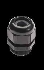
threaded Cable Glands Cable Glands with protection for spiral-shaped cables
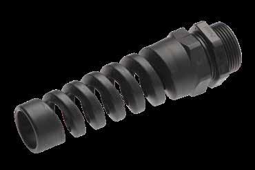
These Cable Glands guarantee an excellent strain relief resistance with waterproof protection (IP68 and IP69). The body is in plastic material (Polyamide or black colored Nylon – Operating temperature -25 ºC to + 100 ºC) or metallic material (Brass with nickel finish – operating temperature -30 ºC to +100 ºC).
They both prevent the cable from twisting when coupling the connectors. The plastic version is provided with an anti-vibration system to prevent the Cable Glands from becoming loose. Compared to other cable retention systems this solution is more economical.
These adapters are available with PG or metric thread and can be used with connector classes DA…PG, DA…M, RA…PG and RA…M. Cable Glands with protection for spiral-shaped cables (only for PG sizes 7 to 21 or metric 12 to 32) are available on request. They eliminate possible damage caused by the cable bending on the cable-connector interface. Therefore these are often used with cables where a small conductor can be easily damaged.
386 Go online for data sheets & assembly instructions. Visit www.radiall.com/vansystem and enter the part number. ACCESSORIES Part Number Short Description Part Number Protected Short Description Protected V ØS Clamping range K Z L L1 VS705021 AL PG7 P VS705041 AL PG7 PP PG 7 2.5-6.5 15 8 32 62 VS705022 AL PG9 P VS705042 AL PG9 PP PG 9 3.5-8 19 8 36 73.5 VS705023 AL PG11 P VS705043 AL PG11 PP PG 11 4-10 22 8 38 86 VS705024 AL PG13.5 P VS705044 AL PG13.5 PP PG 13.5 6-12 24 9 41 98 VS705025 AL PG16 P VS705045 AL PG16 PP PG 16 9-14 27 10 44 111.5 VS705026 AL PG21 P VS705046 AL PG21 PP PG 21 13-18 33 11 49 129 VS705027 AL PG29 P - - PG 29 14-25 42 11 56 VS705028 AL PG36 P - - PG 36 24-32 53 13 66 VS705029 AL PG42 P - - PG 42 35-38 60 13 68 VS705031 AL M12 P VS705051 AL M12 PP M12x1.5 3.5-7 15 8 30 64 VS705032 AL M16 P VS705052 AL M16 PP M16x1.5 4.5-10 19 8 34 86 VS705033 AL M20 P VS705053 AL M20 PP M20x1.5 7-13 25 9 37 101 VS705034 AL M25 P VS705054 AL M25 PP M25x1.5 9-17 30 10 40 125 VS705035 AL M32 P VS705055 AL M32 PP M32x1.5 11-21 36 10 47 149 VS705036 AL M40 P - - M40x1.5 19-28 46 10 52 VS705037 AL M50 P - - M50x1.5 27-35 55 12 62
Plastic Cable Glands
PG
metric
Dimensions in mm
Cable Glands
- PG or metric threaded
Metallic Cable Glands - Short
387 Go online for data sheets & assembly instructions. Visit www.radiall.com/vansystem and enter the part number. ACCESSORIES L Z V K ØS V K ØS L1 Z
Part Number Short Description V ØS Clamping range K Z L VS705001 AL PG7 M PG 7 2-6.5 15 8 32 VS705002 AL PG9 M PG 9 3-8 19 8 36 VS705003 AL PG11 M PG 11 4-10 22 8 38 VS705004 AL PG13.5 M PG 13.5 5-12 24 9 41 VS705005 AL PG16 M PG 16 8-14 27 10 44 VS705006 AL PG21 M PG 21 11-18 33 11 49 VS705007 AL PG29 M PG 29 16-25 42 11 56 VS705008 AL PG36 M PG 36 19-32 53 13 66 VS705009 AL PG42 M PG 42 28-38 60 13 68 VS705011 AL M12 M M12x1.5 3.5-7 15 8 30 VS705012 AL M16 M M16x1.5 4.5-10 19 8 34 VS705013 AL M20 M M20x1.5 7-13 25 9 37 VS705014 AL M25 M M25x1.5 9-17 30 10 40 VS705015 AL M32 M M32x1.5 11-21 36 10 47 VS705016 AL M40 M M40x1.5 19-28 46 10 52 VS705017 AL M50 M M50x1.5 27-35 55 12 62 Metallic
Shielded Dimensions in mm Metallic
Standard Protected Accessories For Connectors Part Number Short Description V ØS Clamping range K Z L On Request AL M12 E M12x1.5 3.5-7 16 6.5 26.5 On Request AL M16 E M16x1.5 4.5-9 20 7 33 On Request AL M20 E M20x1.5 7-13 24 8 37 On Request AL M25 E M25x1.5 9-17 29 8 38.5 VS705067 AL M32 E M32x1.5 11-21 36 9 45.5 On Request AL M40 E M40x1.5 19-28 45 9 48 On Request AL M50 E M50x1.5 27-35 54 10 55.5 Part Number Short Description V ØS Clamping range K Z L On Request AL M25 S M25x1.5 11-18 30 5 37 On Request AL M32 S M32x1.5 16-25 40 5 43
Cable Glands -
Cable Glands
388 Go online for data sheets & assembly instructions. Visit www.radiall.com/vansystem and enter the part number. ACCESSORIES L1 L2 L2 ØD1 ØD2 0.2 x 45° L1 ØD1 0.2 x 45° ØD2 L2 Accessories For Connectors
for inserts L1 L2 L2 ØD1 ØD2 0.2 x 45° L1 ØD1 0.2 x 45° ØD2 L2 Dimensions in mm
inserts
used. Contact size Part Number Short Description ØD1 ØD2 L1 L2 20 VS412501 A HP 20 I 1.6 2.3 14 11 18* VS412502 A HP 18 I - - -16 - 16S VS412503 A HP 16 I 2.2 2.6 15.8 10.8 12 VS412504 A HP 12 I 4.55 3.7 11.95 3.15 8 VS412505 A HP 8 I 7.6 6.4 11.8 3.1 4 VS412506 A HP 4 I 10.9 9.7 11.8 3.1 0 VS412507 A HP 0 I 15 13.5 14.3 4.3 4/0* VS412508 A HP 4/0 I - - - -
* Size 20 / 16 *
Contacts hole plugs
These are employed when not all contact cavities of
are
Wire hole plugs for grommets on request
On request
Contact Crimp Tools
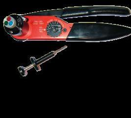
Part Number
VS610001
VS610002
VS610003
VS610004
For the instructions concerning assembly and crimping of contacts please consult the appropriate manuals.
We recommend to respect the following general rules:
• always use the tools recommended by Van-System’s catalogue or manuals
• apply the suggested norms for tool maintenance and calibration
• always use the guide pin when installing the Socket contacts size 20 - 18 - 16 and 12
When installing the contacts in the insert, use isopropyl alcohol as lubricant or the appropriate liquid.
DO NOT USE ALTERNATIVE GREASES OR OILS which could damage the insert and affect the functionality of the connector.
Short Description
CRT-HT120
CRT-784/1
CRT-HT45
PCT-784
Tool
Crimping Tool Cembre HT 120
Crimping Tool Daniels DMC VM8
Crimping Tool Cembre HT 45
Crimping Tool Daniels DMC WA27F VS610005
VS610006
PCT-784A
LOC-784-20
Crimping Tool Daniels WA27-309-2C
Locator (for contacts size 20) Daniels TH1A VS610007
VS610008
VS610009
LOC-784-18
LOC-784
CDI-ME1
Locator (for contacts size 18)
Locator (for ST485 contacts size 16 and 12) Daniels TURRET VH435-1
Crimping Die Cembre ME1 VS610010
VS610011
VS610012
VS610013
VS610014
VS610015
VS610016
VS610017
VS610018
VS610019
VS610020
VS610021
VS610022
VS610023
VS610024
VS610025
VS610026
VS610027
VS610028
VS610029
VS610030
VS610031
VS610032
VS610033
VS610034
VS610035
VS610036
VS610038
VS610040
VS610041
VS610042
VS610043
VS610048
VS610049
VS610050
VS610051
VS610052
VS610053
VS610054
VS610055
VS610056
VS610059
VS610060
VS610061
VS610062
VS610077
VS610080
CDI-ME2
CDI-ME3
CDI-ME5
CDI-ME14
CDI-ME24C
CDI-ME29C
LOC-KVBS-784
FP-784
AB-784
CTIN-784-18/20
CTIN-784-16
CTIN-784-18
CTIN-784-12/1
CTIN-784-12
CTIN-784-8
CTIN-784-4
CTIN-784-4/2
CTIN-784-4/1
CTIN-784-0/1
CTIN-784-0
CTES-784-20
CTES-784-18
CTES-784-16
CTES-784-12
CTES-784-8
CTES-784-4
CTES-784-0
CTES-784-4/0
KTES-784-16
KTES-784-12
KTES-784-8
KTRS-784-12
CRT-HT131
CDI-ME48C
CDI-ME60C
CDI-VS61137
GP-784-20
GP-784-18
GP-784-16
GP-784-12
CDI-VS61138
CDI-ME37C
CDI-ME17C
CDI-ME20C
CDI-ME30C
CDI-ME7
CDI-VS61186
Crimping Die Cembre ME2
Crimping Die Cembre ME3
Crimping Die Cembre ME5
Crimping Die Cembre M14
Crimping Die Cembre M24C
Crimping Die Cembre M29C
Locator (for KT485 contacts)
Foot Pedal for PCT-784 Daniels WA 10A
Adjustable Base Mount for PCT-784 Daniels BM2A
Insertion Tool (for ST485 contacts size 18, 20 and 16-13)
Insertion Tool (for ST485 contacts size 16)
Insertion Tool (for ST485 contacts size 18)
Insertion Tool (for ST485 xx-30, xx-38)
Insertion Tool (for ST485 contacts size 12)
Insertion Tool (for ST485 contacts size 8)
Insertion Tool (for ST485 contacts size 4)
Insertion Tool (for ST485 4-58)
Insertion Tool (for ST485 xx-62)
Insertion Tool (for ST485 xx-78 and xx-90)
Insertion Tool (for ST485 contacts size 0)
Removal Tool (for ST485 contacts size 20)
Removal Tool (for ST485 contacts size 18)
Removal Tool (for ST485 contacts size 16)
Removal Tool (for ST485 contacts size 12)
Removal Tool (for ST485 contacts size 8)
Removal Tool (for ST485 contacts size 4)
Removal Tool (for ST485 contacts size 0)
Removal Tool (for ST485 contacts size 4/0)
Removal Tool (for KT contacts size 16)
Removal Tool (for KT contacts size 12)
Removal Tool (for KT contacts size 8)
Tool to close retention spring (for KT contacts size 12)
Crimping Tool HT 131 C
Crimping Die Cembre ME48C
Crimping Die Cembre ME60C
Crimping Die (for ST485 contacts size 8-22)
Guide Pin Size 20
Guide Pin Size 18
Guide Pin Size 16
Guide Pin Size 12
Crimping Die (for KT485 contacts size 8-38)
Crimping Die Cembre ME37C
Crimping Die Cembre ME17C
Crimping Die Cembre ME20C
Crimping Die Cembre ME30C
Crimping Die Cembre ME7
Crimping Die (for ST485 contacts size 0-135)
389 Go online for data sheets & assembly instructions. Visit www.radiall.com/vansystem and enter the part number. CONTACT CRIMP TOOLS
Contact ST Crimp Tools
CVS-CVB-CVBS-CVBSG-CVBR-GVJ (For Rubber Insert)
4/0
390 Go online for data sheets & assembly instructions. Visit www.radiall.com/vansystem and enter the part number. CONTACT CRIMP TOOLS Contact size Short Description mm2 section AWG section Manual crimp tool Pneumatic crimp tool Locator /Die Insertion tool Removal tool Guide pin Stripping length mm 20 ST485 20P/1/S 0.15÷0.3 26÷22 CRT-784/1 PCT-784 LOC-784-20 CTIN-784-18/20 CTES-784-20 GP-784-20 4 20 ST485 20P/2 0.15÷0.3 26÷22 CRT-784/1 PCT-784 LOC-784-20 CTIN-784-18/20 CTES-784-20 ** 4 20 ST485 20P/3 0.15÷0.3 26÷22 CRT-784/1 PCT-784 LOC-784-20 CTIN-784-18/20 CTES-784-20 ** 4 18 ST485 18P/S 0.15÷0.6 26÷20 CRT-784/1 PCT-784 LOC-784-18 CTIN-784-18/20 CTES-784-18 GP-784-18 4.5 16S ST485 16SP/S 1÷1.5 18÷16 CRT-784/1 PCT-784 LOC-784 CTIN-784-16 CTES-784-16 GP-784-16 6.3 16S ST485 16S-11P/S 0.25÷0.5 22-20 CRT-784/1 PCT-784 LOC-784 CTIN-784-16 CTES-784-16 GP-784-16 6.3 16S ST485 16S-12P/S 0.15÷0.75 20 CRT-784/1 PCT-784 LOC-784 CTIN-784-16 CTES-784-16 GP-784-16 6.3 16S ST485 16S-15P/S 0.75÷1 18 CRT-784/1 PCT-784 LOC-784 CTIN-784-16 CTES-784-16 GP-784-16 6.3 16S ST485 16S-17P/S 0.75 16 ** ** ** ** ** ** 6.3 16S ST485 16S-19P/S 1.5÷2.5 16÷14 CRT-784/1 PCT-784 LOC-784 CTIN-784-16 CTES-784-16 GP-784-16 6.3 16S ST485 16S-20P/S 1÷2 18÷14 CRT-784/1 PCT-784 LOC-784 CTIN-784-16 CTES-784-16 GP-784-16 6.3 16S ST485 16S-26P/S 2.5÷3 12 CRT-784/1 PCT-784 LOC-784 CTIN-784-16 CTES-784-16 GP-784-16 6.8 16 ST485 16P/S 1÷1.5 18÷16 CRT-784/1 PCT-784 LOC-784 CTIN-784-16 CTES-784-16 GP-784-16 6.3 16 ST485 16-08P/S 0.15÷0.2 26÷24 CRT-784/1 PCT-784 LOC-784 CTIN-784-16 CTES-784-16 GP-784-16 6.3 16 ST485 16-12P/S 0.15÷0.75 20 CRT-784/1 PCT-784 LOC-784 CTIN-784-16 CTES-784-16 GP-784-16 6.3 16 ST485 16-13P/S 0.15÷0.6 26÷20 CRT-784/1 PCT-784 LOC-784 CTIN-784-18 CTES-784-16 GP-784-16 6.3 16 ST485 16-14P/S 0.75 18 CRT-784/1 PCT-784 LOC-784 CTIN-784-18 CTES-784-16 GP-784-16 6.3 16 ST485 16-15P/S 0.75÷1 18 CRT-784/1 PCT-784 LOC-784 CTIN-784-16 CTES-784-16 GP-784-16 6.3 16 ST485 16-17P/S 0.5÷1.5 20÷16 CRT-784/1 PCT-784 LOC-784 CTIN-784-16 CTES-784-16 GP-784-16 6.3 16 ST485 16-19P/S 1.5÷2.5 16÷14 CRT-784/1 PCT-784 LOC-784 CTIN-784-16 CTES-784-16 GP-784-16 6.3 16 ST485 16-20P/S 1÷2 18÷14 CRT-784/1 PCT-784 LOC-784 CTIN-784-16 CTES-784-16 GP-784-16 6.3 16 ST485 16-26P/S 2.5÷3 12 CRT-784/1 PCT-784 LOC-784 CTIN-784-16 CTES-784-16 GP-784-16 6.8 12 ST485 12-11P/S 0.5 22-20 ** ** ** ** ** ** 8.3 12 ST485 12-12P/S 0.15÷0.75 20 CRT-784/1 PCT-784 LOC-784 CTIN-784-16 CTES-784-12 GP-784-12 8.3 12 ST485 12-15P/S 0.75÷1 18 CRT-784/1 PCT-784 LOC-784 CTIN-784-16 CTES-784-12 GP-784-12 8.3 12 ST485 12-20P/S 1÷2 18÷14 CRT-784/1 PCT-784 LOC-784 CTIN-784-12 CTES-784-12 GP-784-12 6.5 12 ST485 12-22P/S 2.5 - CRT-784/1 PCT-784 LOC-784 CTIN-784-12 CTES-784-12 GP-784-12 8.3 12 ST485 12P/S 3 12 CRT-784/1 PCT-784 LOC-784 CTIN-784-12 CTES-784-12 GP-784-12 8.3 12 ST485 12-30P/S 4 - CRT-784/1 PCT-784-A LOC-784 CTIN-784-12/1 CTES-784-12 GP-784-12 8.3 12 ST485 12-38P/S 6 - CRT-784/1 PCT-784-A LOC-784 CTIN-784-12/1 CTES-784-12 GP-784-12 8 8 ST485 8P/S - 8 CRT-HT45 - CDI-ME2 CTIN-784-8 CTES-784-8 - 12 8 ST485 8-15P/S 1 18 **** ** **** 8 ST485 8-18P/S 1÷2 18÷14 **** ** **** 8 ST485 8-22P/S 2.5 - CRT-HT45 - CDI-VS61137 CTIN-784-8 CTES-784-8 - 12 8 ST485 8-26P/S 3 12 ** - - - -** 8 ST485 8-30P/S 4 - CRT-HT45 - CDI-ME1 CTIN-784-8 CTES-784-8 - 8 8 ST485 8-38P/S 6 10 CRT-HT45 - CDI-ME2 CTIN-784-8 CTES-784-8 - 12 8 ST485 8-50P/S 10 - CRT-HT45 - CDI-ME2 CTIN-784-8 CTES-784-8 - 12 4 ST485 4P/S 22 4 CRT-HT45 - CDI-ME5 CTIN-784-4 CTES-784-4 - 12 4 ST485 4-26P/S 3**** ** **** 4 ST485 4-30P/S 4**** ** **** 4 ST485 4-38P/S 6 10 CRT-HT45 - CDI-ME2 CTIN-784-4 CTES-784-4 - 12 4 ST485 4-50P/S 10 - CRT-HT45 - CDI-ME2 CTIN-784-4 CTES-784-4 - 12 4 ST485 4-58P/S - 6 CRT-HT45 - CDI-ME3 CTIN-784-4 CTES-784-4 - 12 4 ST485 4-62P/S 16 - CRT-HT45 - CDI-ME5 CTIN-784-4 CTES-784-4 - 12 4 ST485 4-78P/S 25 - CRT-HT45 - CDI-ME5 CTIN-784-4 CTES-784-4 - 12 4 ST485 4-90P/S 35 2 CRT-HT45** ** CTES-784-4 - 14 0 ST485 0P/S 53 0 CRT-HT45 - CDI-ME14 CTIN-784-0 CTES-784-0 - 14 0 ST485 0-45P/S - 8 CRT-HT45 - CDI-ME2 CTIN-784-0 CTES-784-0 - 12 0 ST485 0-50P/S 10 - CRT-HT45 ** CDI-ME2 ** CTES-784-0 ** 12 0 ST485 0-58P/S - 6 ** ** ** ** ** ** 14 0 ST485 0-62P/S 16 - CRT-HT45 ** CDI-ME5 ** ** ** 12 0 ST485 0-78P/S 25 - CRT-HT45 - CDI-ME5 CTIN-784-0 CTES-784-0 - 14 0 ST485 0-80P/S - 3 ** ** ** ** ** - 14 0 ST485 0-90P/S 35 2 CRT-HT45 - CDI-ME14 CTIN-784-0 CTES-784-0 - 14 0 ST485 0-107P/S 50 - CRT-HT45 - CDI-ME14 CTIN-784-0 CTES-784-0 - 14.3 0 ST485 0-135P/S 67.4 2/0 ** ** CDI-VS61186 ** ** - 18 4/0 ST485 4/0-115P/S 53 0 CRT-HT45 - CDI-ME14 ** CTES-784-4/0**
** - CDI-VS61186 ** CTES-784-4/0**
4/0 ST485 4/0-135P/S 67.4 2/0
CRT-HT120 - CDI-ME24C **
**
CRT-HT120 - CDI-ME24C **
**
CRT-HT120 - CDI-ME29C **
** ** On
ST485 4/0-144P/S 70 -
CTES-784-4/0
4/0 ST485 4/0-155P/S 95 -
CTES-784-4/0 -
4/0 ST485 4/0P/S 107÷120 4/0
CTES-784-4/0 -
request (please consult our Sales Office)
Contact ST Whit Louver Crimp Tools
8L ST485 8L-17P/S 1.5 16
8L ST485 8L-23P/S 2.5
8L ST485 8L-35P/S 6 10
8L ST485 8L-46P/S 10 -
0L ST485 0L-62P/S 16 -
0L ST485 0L-76P/S 25 -
0L ST485 0L-89P/S 35 -
0L ST485 0L-105P/S 50
4/0L ST485 4/0L-115P/S 53 0 CRT-HT45 - CDI-ME14
4/0L ST485 4/0L-135P/S** 67.4 2/0 **
4/0L ST485 4/0L-144P/S 70 -
4/0L ST485 4/0L-155P/S 95 -
4/0L ST485 4/0LP/S 107÷120 4/0
Contact KT Crimp tools
GVJ (For Thermoplastic Insert)
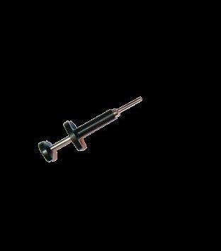
Contact KT Whit Louver Crimp tools
GVJ (For
Insert)
391 Go online for data sheets & assembly instructions. Visit www.radiall.com/vansystem and enter the part number. CONTACT CRIMP TOOLS
size Short Description mm2 section AWG section Manual crimp tool Pneumatic crimp tool Locator /Die Insertion tool Removal tool Guide pin Stripping length mm
Contact
** ** ** ** ** ** **
** ** ** ** ** ** **
-
** ** ** ** ** **
**
** ** ** ** ** **
**
** ** ** ** ** ** **
** ** ** ** ** ** **
** ** ** ** ** ** **
** ** ** ** ** ** **
-
- -
CRT-HT120 - CDI-ME24C
CRT-HT120
CDI-ME24C
-
CRT-HT120
CDI-ME29C ** On request (please consult our Sales Office)
-
Contact size Short Description mm2 section AWG section Manual crimp tool Pneumatic crimp tool Locator /Die 16 KT485 16-12P/S 0.5÷0.75 - CRT-784/1 PCT-784 LOC-KVBS-784 16 KT485 16-20P/S 1÷2 18÷14 CRT-784/1 PCT-784 LOC-KVBS-784 16 KT485 16-26P/S 2.5÷3 - CRT-784/1 PCT-784 LOC-KVBS-784 12 KT485 12-12P/S 0.6 20 CRT-784/1 PCT-784 LOC-KVBS-784 12 KT485 12-20P/S 1÷2 18÷14 CRT-784/1 PCT-784 LOC-KVBS-784 12 KT485 12-26P/S** 2.5÷3 - CRT-784/1 PCT-784 LOC-KVBS-784 12 KT485 12-30P/S 4 - CRT-784/1 PCT-784 LOC-KVBS-784 12 KT485 12-38P/S 6 - CRT-784/1 PCT-784A LOC-KVBS-784 KTES-784-12 RS-784-12 9.5 8 KT485 8-15P/S 1 - CRT-HT45** KTES-784-8 - 12 8 KT485 8-22P/S 2.5 - CRT-HT45 - CDI-VS61137 ** - 13.5 8 KT485 8-30P/S** 4 - CRT-HT45** KTES-784-8 - 13.5 8 KT485 8-38P/S 6 - CRT-HT45 - CDI-VS61138 KTES-784-8 - 13.5 8 KT485 8-50P/S** 10 - CRT-HT45 -** - 13.5
Contact size Short Description mm2 section AWG section Manual crimp tool Pneumatic crimp tool Locator /Die Removal tool Tool To Close Retention Spring Stripping length mm 4/0L KT485 4/0L-115S 53 0 CRT-HT45 - CDI-ME14 CTES-784-4/0 ** 4/0L KT485 4/0L-144S 70 - CRT-HT120 - CDI-ME24C CTES-784-4/0 ** 4/0L KT485 4/0L-155S 95 - CRT-HT120 - CDI-ME24C CTES-784-4/0 ** 4/0L KT485 4/0L-S 107÷120 4/0 CRT-HT120 - CDI-ME29C CTES-784-4/0 ** **
Removal tool KTES-784
On request (please consult our Sales Office)
CVS-CVB-CVBS-CVBSG-CVBR-GVJ (For Rubber Insert)
Thermoplastic
Tools
Connector Assembly
• With exchangeable plastic jaws scratchproof (for treated surfaces)
• For connectors and couplings with screw
• Ideal for tightening and loosening backshell screw connections, plastic pipe fittings and round union nuts connection
• For gentle loosening of backshell
• 25 adjustment positions, box-joint design
• Ergonomic handle geometry
• Pliers chrome plated, handles with non-slip plastic coating
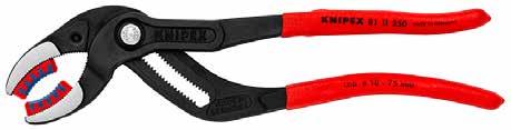
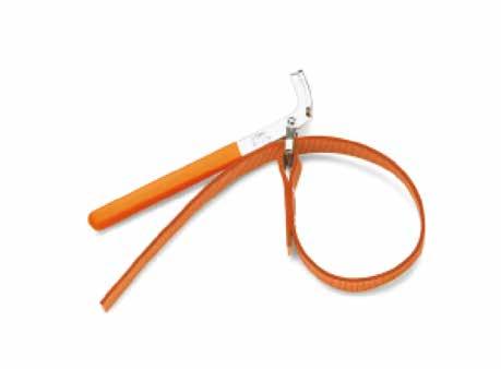
392 Go online for data sheets & assembly instructions. Visit www.radiall.com/vansystem and enter the part number. ACCESSORIES
Part Number Short Description Tool L mm Weight g Working Capacity Ø Adjustment positions Material Handle Type VS610074 SW-KN1075 Pipe Wrench 250 355 10 - 75 Ø mm 25 Chrome Vanadium Electric Steel Plastic L
Pipe Wrench
L Ø
Part Number Short Description Tool L mm Ø max mm Weight g VS610073 SW-BT1490-1 Strap Wrenches 225 160 290
Strap Wrenches
393 Go online for data sheets &
Visit www.radiall.com/vansystem and enter the part number.
assembly instructions.
394 Go online for data sheets & assembly instructions. Visit www.radiall.com/vansystem and enter the part number. Index Product Selection Guide - Index 3 Part number explanation 4 General Characteristics 8 CVS - General Characteristics 9 CVB - General Characteristics 10 CVBS - General Characteristics 11 CVBSG - General Characteristics 12 CVBR - General Characteristics 13 GVJ - General Characteristics 14 Circular Connectors 15 General Characteristics - Shells - Shielding characteristics 16 General Characteristics - Shells - Material and Finish 17 General Characteristics - Inserts 18 General Characteristics - Rated Current and Rated Voltage 19 General Characteristics - Contacts - electrical characteristics 20 General Characteristics 21 Contacts - Part number explanation 22 Insulating Inserts And Grommets - Part number explanation 23 Insulating Inserts and Grommets - List by Shell size 50 Insulating Inserts and Grommets - List by contacts total quantity 55 Alternate Insert Positions 60 Connector - Shell 66 Connector Class - Backshell Characteristics 68 CVBS - Bayonet Connector with protected mating ramps - Shell - Backshell 69 Front Mounting Receptacle (00) with Backshell Class (A - DA - RA) 70 Front Mounting Receptacle (00) with Backshell Class (LA - LDA - LRA) 72 Front Mounting Receptacle (00) with Backshell Class (AF - F) 74 Front Mounting Receptacle (00) with Backshell Class (LAF - LF) 76 Front Mounting Receptacle (00) with Backshell Class (AC - ACF) 78 Front Mounting Receptacle (00) with Backshell Class (ACB) 80 Front Mounting Receptacle (00) with Backshell Class (LAC - LACF) 82 Front Mounting Receptacle (00) with Backshell Class (AB) 84 Front Mounting Receptacle (00) with Backshell Class (ASF) 86 Front Mounting Receptacle (00) with Backshell Class (DA..M - RA..M DA..PG - RA..PG) 88 Front Mounting Receptacle (00) with Backshell Class (DA..MH - RA..MH DA..PH - RA..PH) 90 Front Mounting Receptacle (00) with Backshell Class (AR - R) 92 Front Mounting Receptacle (00) with Backshell Class (AG - G) 94 Front Mounting Receptacle (00) with Backshell Class (AG2 - G2) 96 Front Mounting Receptacle (00) with Backshell Class (ASB1 - SB1) 98 Front Mounting Receptacle (00) with Backshell Class (AGV - GV) 100 Front Mounting Receptacle (00) with Backshell Class (SB) 102 Front Mounting Receptacle (020) without Accessories (To be purchased separately) 104 Front Mounting Receptacle (02 - 02A - 02R) unable to Accept Rear Accessories 106 Rear Mounting Receptacle (030) without Accessories (To be purchased separately) 108 Rear Mounting Receptacle (030) with Backshell Class (A - DA - RA) 110 Rear Mounting Receptacle (030) with Backshell Class (AF - F) 112 Rear Mounting Receptacle (030) with Backshell Class (AC - ACF) 114 Rear Mounting Receptacle (030) with Backshell Class (DA..M - RA..M) 116 Rear Mounting Receptacle (030) with Backshell Class (AR - R) 118 Rear Mounting Receptacle (030) with Backshell Class (AG - G) 120 Rear Mounting Receptacle (030) with Backshell Class (AST - ST) 122
Rear Mounting Receptacle (030) with Backshell Class (AST..M - ST..M)
Rear Mounting Receptacle (030) with Backshell Class (AST..FS - ST..FS)
Rear Mounting Receptacle (03 - 03A - 03R) unable to accept Rear Accessories
In-Line Receptacle (01) with Backshell Class (A - DA - RA)
In-Line Receptacle (01) with Backshell Class (LA - LDA - LRA)
In-Line Receptacle (01) with Backshell Class (AF - F)
In-Line Receptacle (01) with Backshell Class (LAF - LF)
In-Line Receptacle (01) with Backshell Class (AC - ACF)
In-Line Receptacle (01) with Backshell Class (ACB)
In-Line Receptacle (01) with Backshell Class (LAC - LACF)
Receptacle (01) with Backshell Class (AB)
In-Line Receptacle (01) with Backshell Class (ASF)
In-Line
Plug
Plug
Go online for data sheets & assembly instructions.
395
Visit www.radiall.com/vansystem and enter the part number.
Index
124
126
128
130
132
134
136
138
140
142
144
In-Line
146
Receptacle (01) with Backshell Class (DA...M - RA...M - DA...PG - RA...PG) 148 In-Line Receptacle (01) with Backshell Class (DA...MH - RA...MH - DA...PH - RA...PH) 150 In-Line Receptacle (01) with Backshell Class (AR - R) 152 In-Line Receptacle (01) with Backshell Class (AG - G) 154 In-Line Receptacle
with Backshell Class (AG2 - G2) 156 In-Line Receptacle (01) with Backshell Class (ASB1 - SB1) 158 In-Line Receptacle (01) with Backshell Class (AGV - GV) 160 In-Line Receptacle (01) with Backshell Class (SB) 162 Rear Mounting Receptacle (07/07R) unable to accept Rear Accessories 164 Rear Mounting Receptacle (070) without Accessories (To be purchased separately) 166 Plug Connector (06) with Backshell Class (A - DA - RA) 168 Plug Connector (06) with Backshell Class (LA - LDA - LRA) 170 Plug Connector (06) with Backshell Class (AF - F) 172 Plug Connector (06) with Backshell Class (LAF - LF) 174 Plug Connector (06) with Backshell Class (AC - ACF) 176 Plug Connector (06) with Backshell Class (ACB) 178 Plug Connector (06) with Backshell Class (LAC - LACF) 180 Plug Connector (06) with Backshell Class (AB) 182 Plug Connector (06) with Backshell Class (ASF) 184 Plug Connector (06) with Backshell Class (DA..M - RA..M DA..PG - RA..PG) 186 Plug Connector (06) with Backshell Class (DA..MH - RA..MH DA..PH - RA..PH) 188 Plug Connector (06) with Backshell Class (AR - R) 190 Plug Connector (06) with Backshell Class (AG - G) 192 Plug Connector (06) with Backshell Class (DA..FS - RA..FS) 194 Plug Connector (06) with Backshell Class (DA..MTG - RA..MTG) 196 Plug Connector (06) with Backshell Class (AG2 - G2) 198 Plug Connector (06) with Backshell Class (AWN - WN) 200 Plug Connector (96) with Backshell Class (AC - ACF) 202 Plug Connector (96) with Backshell Class (DA..M - RA..M DA..PG - RA..PG) 204 Plug Connector (96) with Backshell Class (DA..FS - RA..FS) 206 Plug Connector (96) with Backshell Class (DA..MTG - RA..MTG) 208
Connector (96) with Backshell Class (AG2 - G2) 210
Connector (96) with Backshell Class (ASB1 - SB1) 212 Plug Connector (96) with Backshell Class (AGV - GV) 214 Plug Connector (96) with Backshell Class (SB) 216 Plug Connector (96) with Backshell Class (AMK - MK) 218
Connector (08) with 90° Elbow Class (A - DA - RA) 220
(01)
Plug
Plug
Plug
Connector
with 90° Elbow Class (AF - F) 222
(08)
Connector (08) with 90° Elbow Class (AC - ACF) 224
Index
Plug Connector (08) with 90° Elbow Class (ACB)
Plug Connector (08) with 90° Elbow Class (DA...M - RA...M - DA...PG - RA...PG)
Plug Connector (98) with 90° Elbow Class (AC - ACF)
Plug Connector (98) with 90° Elbow Class (DA...M - RA...M - DA...PG - RA...PG)
Plug Connector with heavy duty coupling nut (65) with Backshell Class (A - DA - RA)
Plug Connector with rubber covered coupling nut (06..GG) with Backshell Class (A - DA - RA)
Plug Connector with rubber covered coupling nut (06..GG) with Backshell Class (AC - ACF)
Plug Connector with rubber covered coupling nut (06..GG) with Backshell Class (DA..M - RA..M DA..PG - RA..PG)
Plug Connector with rubber covered coupling nut (96..GG) with Backshell Class (A - DA - RA)
Plug Connector with rubber covered coupling nut (08..GG) with 90° Elbow Class (A - DA - RA)
Plug Connector with rubber covered coupling nut (08..GG) with 90° Elbow Class (AC - ACF)
Plug Connector with rubber covered coupling nut (98..GG) with 90° Elbow Class (A - DA - RA)
Plug Connector with rubber covered coupling nut (short version) (61..GG) with Backshell Class (A - DA - RA)
Plug Connector with rubber covered coupling nut (short version) (61..GG) with Backshell Class (AC - ACF)
Plug Connector with rubber covered coupling nut (short version) (61..GG) with Backshell Class (DA..M
Plug Connector with rubber covered
Connector with
396 Go online for data sheets
assembly instructions. Visit www.radiall.com/vansystem and enter the part number.
&
226
228
230
232
234
236
238
240
242
244
246
248
250
252
- RA..M DA..PG - RA..PG) 254
Connector
rubber covered coupling nut
version)
with Backshell Class (AST - ST) 256
coupling
Backshell Class (AST..M - ST..M) 258 Plug Connector
rubber covered coupling nut
version)
with Backshell Class (AST..FS
ST..FS) 260
rubber covered coupling nut
version)
with 90° Elbow Class (A - DA - RA) 262 Plug Connector with rubber covered coupling nut (short version) (81..GG) with 90° Elbow Class (AST..M - ST..M) 264 Front Mounting Receptacle (26) unable to Accept Rear Accessories 266 Front Mounting Receptacle, heavy duty coupling nut (265) unable to Accept Rear Accessories 268 Through-Bulkhead Connector (TB) 270 Dummy Receptacle Connector (05) 272 CVBSG - Bayonet Connector with external insulated coating - Shell - Backshell 275 Front Mounting Receptacle (00) with Backshell Class (DA...M - RA...M) 276 Rear Mounting Receptacle (030) with Backshell Class (DA...M - RA...M) 278 Rear Mounting Receptacle (030) with Backshell Class (DA...FS - RA...FS) 280 Rear Mounting Receptacle (030) with Backshell Class (DA...MTG - RA...MTG) 282 Plug Connector (06) with Backshell Class (DAM - RAM) 284 Plug Connector (06) with Backshell Class (DA..M - RA..M) 286 Plug Connector (06) with Backshell Class (DA..FS - RA..FS) 288 Plug Connector (06) with Backshell Class (DA..MTG - RA..MTG) 290 Plug Connector (06) with Backshell Class (AMK - MK) 292 Plug Connector (96) with Backshell Class (AMK - MK) 294 Plug Connector
90° Elbow Class
RAM) 296 Plug Connector (08) with 90° Elbow Class (DA..M - RA..M) 298 Plug Connector (08) with 90° Elbow Class (DA..FS - RA..FS) 300 Plug Connector (08) with 90° Elbow Class (DA..MTG - RA..MTG) 302 Plug Connector with rubber covered coupling nut (short version) (61) with Backshell Class (DAM - RAM) 304 Plug Connector with rubber covered coupling nut (short version) (61) with Backshell Class (DA..M - RA..M) 306 Plug Connector with rubber covered coupling nut (short version) (81) with 90° Elbow Class (DA..M - RA..M) 308 CVBR - Bayonet Connector roller studs - for harsh applications - Shell - Backshell 311 Plug Connector (06) with Backshell Class (A - DA - RA) 312 Plug Connector (06) with Backshell Class (AF - F) 314 Plug Connector (08) with 90° Elbow Class (A - DA - RA) 316 GVJ - Oversize Bayonet Connector - Shell - Backshell 319 Front Mounting Receptacle (00) with Backshell Class (A - DA - RA) 320 Front Mounting Receptacle (00) with Backshell Class (AC - ACF) 322 Front Mounting Receptacle (00) with Backshell Class (DA..M - RA..M DA..PG - RA..PG) 324 Front Mounting Receptacle (020) without Accessories (To be purchased separately) 326
Plug
with
(short
(61..GG)
nut (short version) (61..GG) with
with
(short
(61..GG)
-
Plug
(short
(81..GG)
(08) with
(DAM -
397 Go online for data sheets & assembly instructions. Visit www.radiall.com/vansystem and enter the part number. Index Rear Mounting Receptacle (038) with 90° Elbow Class (A - DA - RA) 328 Rear Mounting Receptacle (038) with 90° Elbow Class (AC - ACF) 330 Rear Mounting Receptacle (038) with 90° Elbow Class (DA..M - RA..M) 332 Plug Connector with rubber covered coupling nut (06) with Backshell Class (A - DA - RA) 334 Plug Connector with rubber covered coupling nut (06) with Backshell Class (AC - ACF) 336 Plug Connector with rubber covered coupling nut (06) with Backshell Class (DA..M - RA..M DA..PG - RA..PG) 338 Plug Connector with rubber covered coupling nut (08) with 90° Elbow Class (A - DA - RA) 340 Plug Connector with rubber covered coupling nut (08) with 90° Elbow Class (AC - ACF) 342 Plug Connector with rubber covered coupling nut (08) with 90° Elbow Class (DA...M - RA...M) 344 GVJG - Oversize Bayonet Connector with external insulated coating 346 Plug Connector with rubber covered coupling nut (06) with Backshell Class (DA..M - RA..M) 346 Connector Shell - Receptacle mounting holes option 348 Connector Shell - Panel drilling dimensions 349 Connector Shell - Mounting panel characteristics 350 Contacts - Part number explanation 351 Solder Contacts - ST - For Rubber insert 352 Crimp Contacts - ST - For Rubber insert 354 Crimp Contacts with Louver - ST - For Rubber insert 358 Crimp Contacts with Touch Proof - ST - For Rubber insert 359 Crimp Contacts Close Entry - ST - For Rubber insert 360 Contacts FMLB First Mate Last Break - ST - For Rubber insert 361 Contacts AO Advance Opening Contacts - ST - For Rubber insert 362 ST Contacts - for Lug 363 KT Contacts - for thermoplastics inserts 364 KT Contacts with Louver - for thermoplastics inserts 365 Crimp Adapters 366 Coaxial Contacts - For Rubber insert 367 Thermocouple Contacts 368 Thermocouple Contacts - Solder 370 Thermocouple Contacts - Crimp 371 PCB Tail - Contacts 372 Accessories For Connectors 373 Caps for Bayonet Connectors 374 Caps for Threaded Connectors 376 Protective Plastic Dust Caps 378 Connector Closure Plate 379 Connector Mounting Gaskets 380 G3 Shielded Gaskets 381 Cable-Clamps A type 382 Bushing for Cable-Clamps A type 383 Cable-Clamps C type 384 Bushing for Cable-Clamps C type 385 Cable Glands - PG or metric threaded 386 Contacts hole plugs for inserts 388 Contact Crimp Tools 389 Contact ST Crimp Tools 390 Contact KT Crimp tools 391 Tools 392
Go online for data sheets & assembly
Visit www.radiall.com/vansystem and enter the part number.
398
instructions.
Safety
Information regarding the use of the product within recommended safety limits
To use the connectors described in this catalogue according to the necessary safety requirements we suggest you apply the following criteria:
• use the connectors and connected cables within their electrical and environmental limits
• follow the characteristics of each version (shell, class and type of strain relief) and carefully choose the appropriate connector for the required use
• make sure to respect the procedures regarding the correct assembly of connectors and the crimping of contacts
• any connector damaged during shipment, storage, assembly or use should be replaced
• never uncouple the connectors when under power
• always protect the parts against shock when the circuit is under power
• always check the circuit before putting it under power
• consult Radiall Italia Srl if in doubt
• the user must take final responsibility for electrical safety Radiall Italia Srl reserves the right to amend the specifications of this catalogue without issuing prior notice.
For the instructions concerning assembly and crimping of contacts please consult the appropriate tools manuals.
We recommend to respect the following general rules:
• to be used always the tools recommended by Radiall Italia Srl’s catalogue or manuals
• to be applied the suggested norms for tool maintenance and calibration
DO NOT USE ALTERNATIVE GREASES OR OILS which could damage the insert and affect the functionality of the connector. Radiall Italia Srl reserves the right to amend the specifications of this catalogue without issuing prior notice.
The data defined in this document are given as an indication. In the effort to improve our products, we reserve the right to make any change judged necessary.
399 Go online for data sheets & assembly instructions. Visit www.radiall.com/vansystem and enter the part number.
2022 EDITION 05.2022
050.RAIL020 PRINTED IN ITALY
www.radiall.com
FRANCE
RADIALL S.A.
Tel +33149353535 info@radiall.com
www.vansystem.eu
ITALY
Radiall Italia S.r.l.
Tel. +39023569931 info.vansystem@radiall.com
