
HIGH FREQUENCY CONNECTORS: N 18 GHZ/ N 18 GHZ SELF-LOCK/TNC 18 GHZ/TNC 18 GHZ SELF-LOCK/SMA 2.9/SMA 2.9 SELF-LOCK/2.4 MM R143/R127/R327/R163
SIMPLIFICATION IS OUR INNOVATION Visit www.radiall.com for more information SECTION 11
11 Table of Contents
N 18 GHZ/N 18 GHZ SELF-LOCK/TNC 18 GHZ/TNC 18 GHZ SELF-LOCK/SMA 2.9/SMA 2.9 SELF-LOCK/2.4 MM | 11-1 SIMPLIFICATION IS OUR INNOVATION Visit www.radiall.com for more information N 18 GHZ Introduction 11-2 Interface ��������������������������������������������������������������������������� 11-3 Characteristics 11-4 Plugs & Jacks �������������������������������������������������������������������� 11-5 Adapters ��������������������������������������������������������������������������� 11-5 N 18 GHZ SELF-LOCK Introduction ��������������������������������������������������������������������� 11-6 Plugs 11-7 to 11-8 TNC 18 GHZ Introduction ��������������������������������������������������������������������� 11-9 Interface 11-9 Characteristics �������������������������������������������������������������� 11-10 Plugs 11-11 Jacks ����������������������������������������������������������������� 11-11 to 11-13 Receptacles 11-13 Adapters 11-14 Caps �������������������������������������������������������������������������������� 11-14 TNC 18 GHZ SELF-LOCK Introduction ������������������������������������������������������������������� 11-15 Plugs 11-16 Section
SMA 2.9 Introduction 11-17 Interface ������������������������������������������������������������������������� 11-18 Characteristics 11-19 Plugs ������������������������������������������������������������������������������� 11-20 Jacks & Receptacles ��������������������������������������� 11-20 to 11-21 Glass Bead 11-21 In Series Adapters ��������������������������������������������������������� 11-21 Between Series Adapters 11-22 Panel Drilling ����������������������������������������������������������������� 11-22 SMA 2.9 SELF-LOCK Introduction 11-23 Characteristics �������������������������������������������������������������� 11-24 Plugs 11-25 2.4 MM Introduction 11-26 Interface 11-26 Characteristics �������������������������������������������������������������� 11-27 Plugs, Jacks & Receptacles 11-28 to 11-29 Glass Bead ��������������������������������������������������������������������� 11-29 In Series Adapters 11-30 Panel Drilling ����������������������������������������������������������������� 11-30
INTRODUCTION
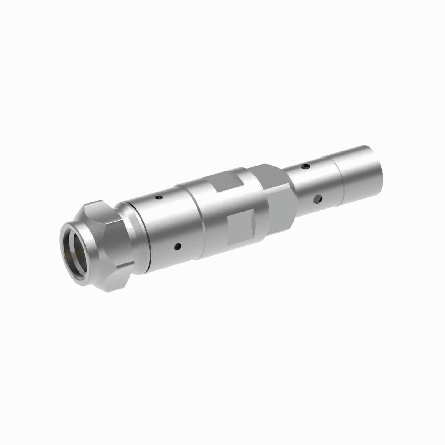
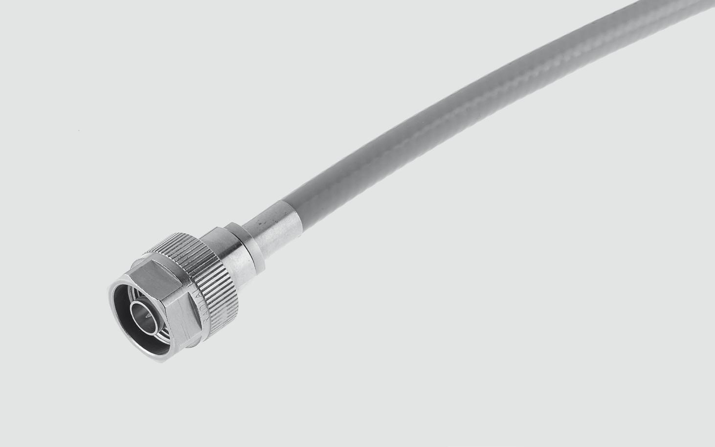
N 18 connectors are 50 ohm precision N Type connectors designed to perform through 18 GHz N connectors are a popular medium sized option commonly used in microwave and RF applications that require high power handling and good electrical performance� Radiall Type N connector interfaces utilizes a PTFE (Teflon) dielectric. The male connectors are provided with a 19 mm (3/4 in.) hex coupling nut so they can be properly torqued. Connector bodies are made from stainless steel, and contacts are made from gold plated and heat treated beryllium copper contacts to insure long life and reliability.
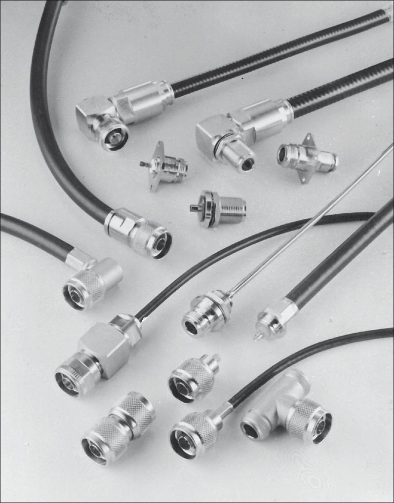
Radiall offers N connectors for semi-rigid and low loss flexible cables, receptacles and precision adapters.
Connectors for low loss flexible cables and TestPro cables are not detailed in this section. They are available in our cable assembly offer.
TYPE N 18 DESIGN FEATURES
• Excellent performance up to 18 GHz
• Low VSWR and insertion loss
• Highly robust construction for reliability
• Superior interface environmental seal
• High power capability
11-2 | N 18 GHZ/N 18 GHZ SELF-LOCK/TNC 18 GHZ/TNC 18 GHZ SELF-LOCK/SMA 2.9/SMA 2.9 SELF-LOCK/2.4 MM SIMPLIFICATION IS OUR INNOVATION Visit www.radiall.com for more information
N 18 GHz
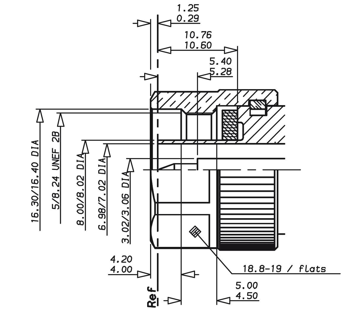
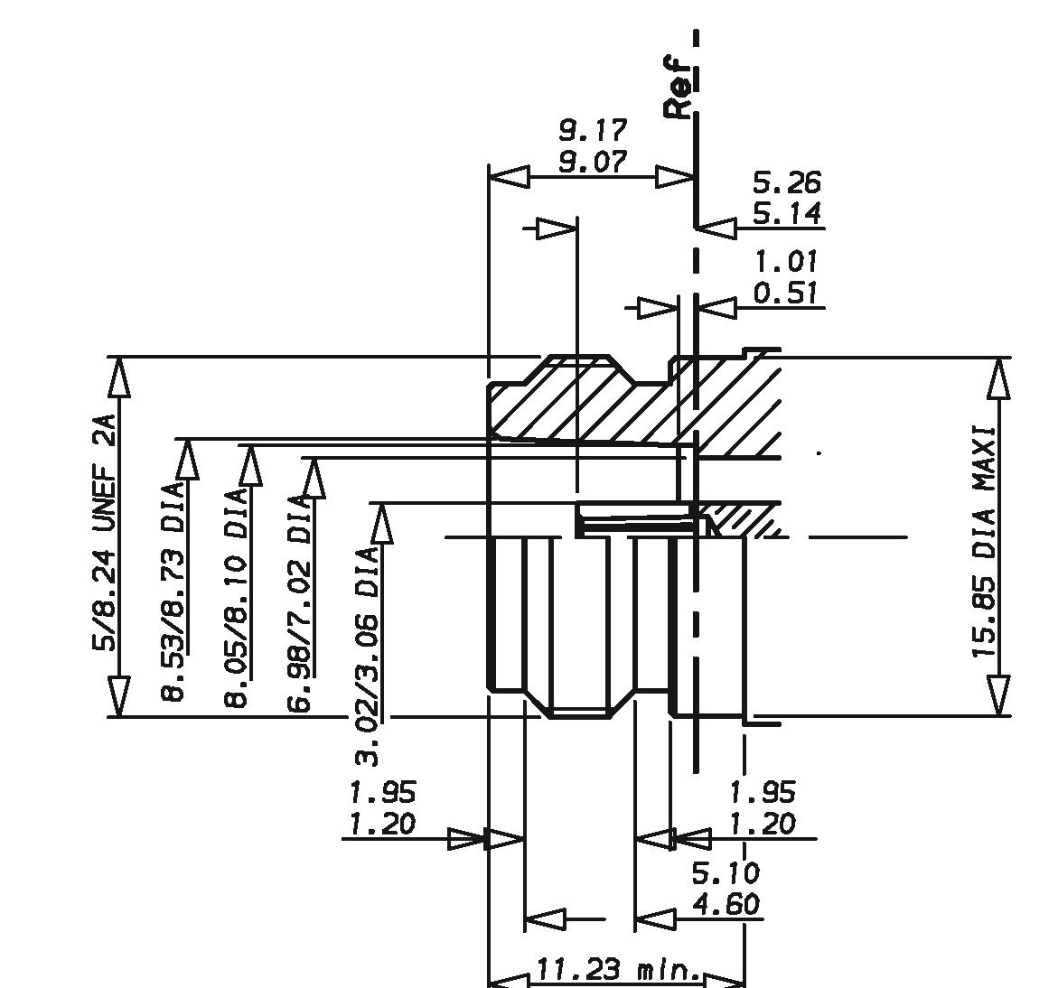
INTERFACE
N 18 GHZ/N 18 GHZ SELF-LOCK/TNC 18 GHZ/TNC 18 GHZ SELF-LOCK/SMA 2.9/SMA 2.9 SELF-LOCK/2.4 MM | 11-3 SIMPLIFICATION IS OUR INNOVATION Visit www.radiall.com for more information N 18 GHz
the interface
IMPORTANT: the 50Ω and the 75Ω connectors are NOT INTERMATEABLE, results in
destruction.
PLUG JACK MM INCH 0 29 0114 1 25 049 3 �02 �1189 3 06 1204 4 00 157 4 20 165 4 50 177 5 00 197 5 28 208 5 40 2126 6 �98 � 2748 7 02 2764 8 00 315 8 �02 � 316 10 60 417 10 76 423 16 30 642 16 40 646 18 80 740 19 00 748 MM INCH 0 51 020 1 01 0397 1� 20 �0472 1 95 0767 3 02 1189 3 06 1204 4 60 1811 5 10 201 5 14 202 5 26 207 6 �98 � 2748 7 02 2764 8 05 317 8 �10 � 319 8 53 336 8 73 3437 9 07 357 9 17 361 11 23 442 15 85 624
MIL-C-39012
tighter tolerances
solid outer contact.
Notes Mating dimensions are
nominal with
and
CHARACTERISTICS
TEST / CHARACTERISTICS
ELECTRICAL CHARACTERISTICS
Impedance
Typical V.S.W.R. • Straight Connector • Right Angle Connector
Insertion Loss
VALUES / REMARKS
0.1 √F (GHz) dB
Leakage - 90 dB (2 to 3 GHz)
Insulation Resistance
Contact Resistance
Outer Contact
Inner Contact
Dielectric Withstanding Voltage
MECHANICAL CHARACTERISTICS
Coupling Torque
ENVIRONMENTAL CHARACTERISTICS
Vibration
MΩ min
Ncm (6 Ibf) min
MIL-STD-1344 Method 2005 Condition 4 Shock
Thermal Shock
Corrosion (Salt Mist)
High Temperature Test
Damp Heat
Low Pressure Immersion
Resistance to Fluids Contamination
MATERIALS
PLATING
MIL-STD-1344 Method 2004 Condition G
MIL-STD-1344 Method 1003 Condition A
MIL-STD-1344 Method 1001 Condition B
CECC 22000/4 7 2
CECC 22000/4 6 6
EN2591 AECMA TestC14
EN2591 AECMA TestC15
Body Stainless Steel
Center Contact Beryllium Copper and Brass
Coupling Nut Brass
Fluorosilicon or Fluorocarbon
Insulator PTFE or Polyetherimid Resin Gasket
Body Passivated
Center Contact Gold
Coupling Nut Nickel
11-4 | N 18 GHZ/N 18 GHZ SELF-LOCK/TNC 18 GHZ/TNC 18 GHZ SELF-LOCK/SMA 2.9/SMA 2.9 SELF-LOCK/2.4 MM SIMPLIFICATION IS OUR INNOVATION Visit www.radiall.com for more information N 18 GHz
50Ω
DC - 18 GHz
Frequency Range
With SHF Cables 1 10 at 18 GHz 1�15 at 18 GHz
<
RF
5000
•
After Environment Test 2 mΩ max N � A � Initial 1.5 mΩ max 2 mΩ max Peak Power
5000 W Average Power
Level,
2000 W at 0 1 GHz 600 W at 1 GHz 150 W at 10 GHz .085" Semi-Rigid Cable .141" Semi-Rigid Cable
• At Sea Level • At 70000 feet 1000 Vrms 250 Vrms 1500 Vrms 375 Vrms Voltage Rating • At Sea Level • At 70000 feet 335 Vrms 85 Vrms 500 Vrms 125 Vrms RF High Potential Withstanding Voltage 670 Vrms 1000 Vrms Corona Level 250 Vrms 375 Vrms
•
(At Sea Level)
(At Sea
25 °C)
Durability 500 Matings Cable Retention Force 136 N (31 Ibf) 272 N (61 Ibf)
160
27
Recommended
Ncm (14 Ibf.in) Contact Captivation
Temperature
Standard Connectors - 65 °C + 165 °C Connectors for Semi-Rigid Cable - 40 °C + 125 °C
Range
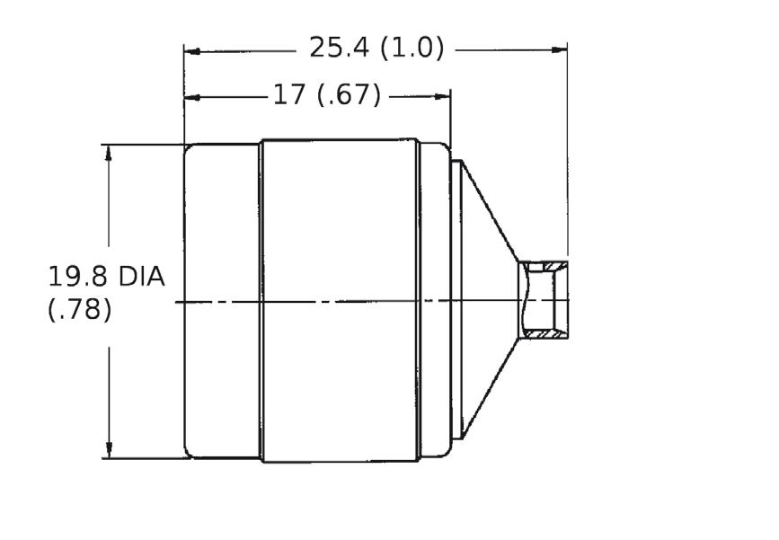
RG402 �141" 4000-1563-009
RG405 085" 4000-1563-010
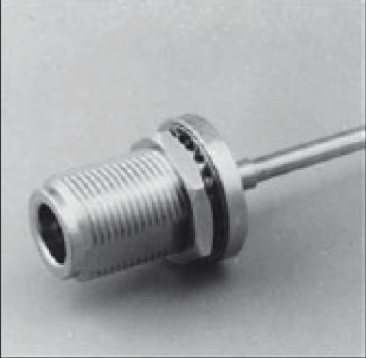
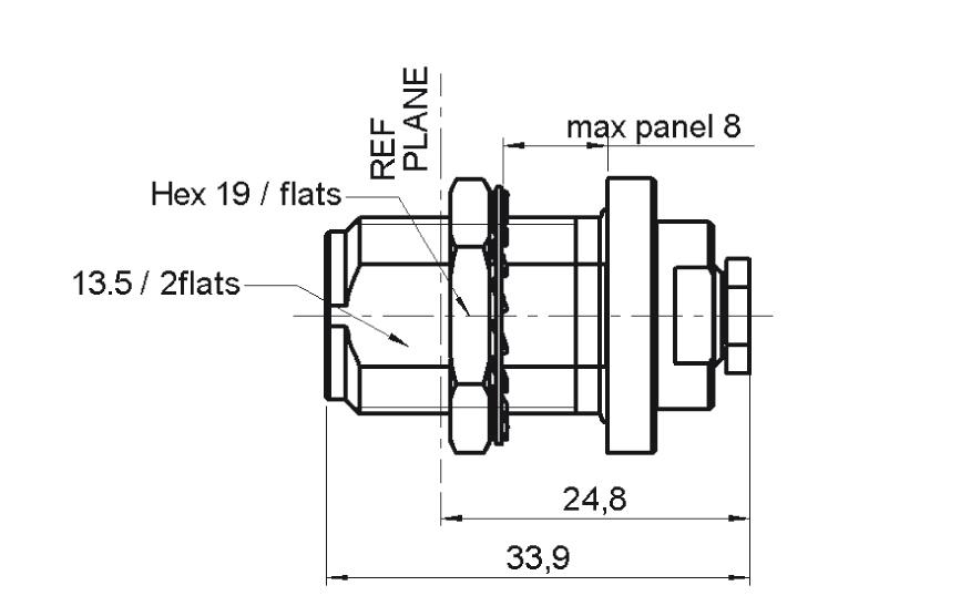
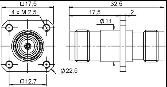
BULKHEAD STRAIGHT JACKS, FOR SEMI-RIGID CABLES (PANEL SEALED)
RG405 085" 4501-9543-010
RG402 141" 4501-9543-009 R163 337 001
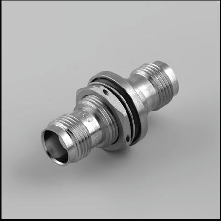
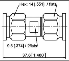
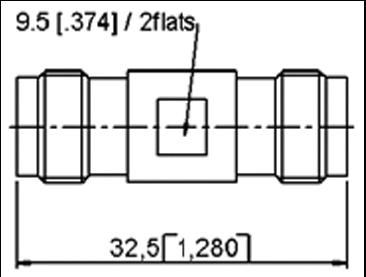
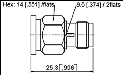
IN SERIES ADAPTERS [2]
Notes
1. N18 GHz plugs for SHF high frequency flexible cable are available as cable assemblies only. Consult us for standard N18 GHz cable assembly part numbers. 2. 7mm air line adapters also available upon request.
N 18 GHZ/N 18 GHZ SELF-LOCK/TNC 18 GHZ/TNC 18 GHZ SELF-LOCK/SMA 2.9/SMA 2.9 SELF-LOCK/2.4 MM | 11-5 SIMPLIFICATION IS OUR INNOVATION Visit www.radiall.com for more information N 18 GHz
GROUP DIA. PART NUMBER CAPTIVE CENTER CONTACT MATERIAL NOTE
CABLE GROUP CABLE
Yes Stainless Steel Direct Solder
GROUP DIA. PART NUMBER CAPTIVE CENTER CONTACT PANEL DRILLING MATERIAL NOTE
CABLE GROUP CABLE
Yes P14 Stainless
Steel Solder Clamp / Rear Mount
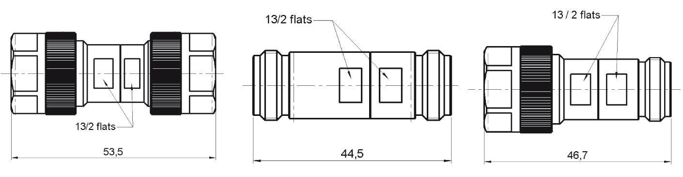
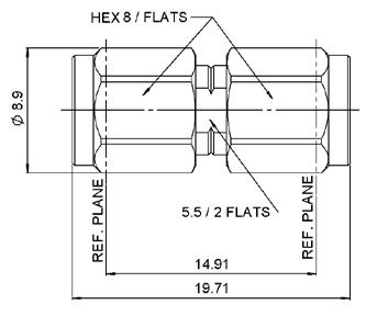
FIG. 1
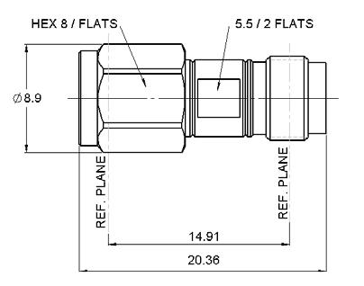
FIG. 2
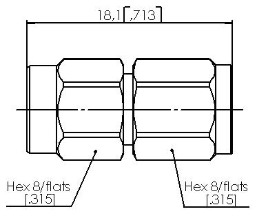
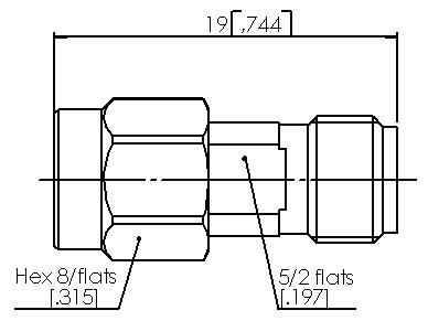
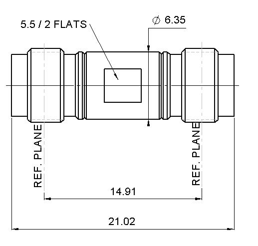
PART NUMBER FIG. DIMENSION (MM) NOTE R163 703 001 1 53.5 (2.106) Male - Male R163 705 001 2 44.5 (1.752) Female - Female R163 708 001 3 46.7 (1.838) Male - Female
FIG. 3
N 18 GHz Self-Lock
INTRODUCTION
Radiall introduces a new innovative technology in response to market demands to eliminate locking wires
Radiall’s Self-Lock RF connectors are the perfect solution to provide secure connection-facing vibrations experienced in aerospace applications.
The Self-Locking design is intended to eliminate the need for safety wires and saves many hours, the locking feature is achieved via a spring loaded, corrugated washer
Self-Lock connectors are intermatable with any standard jack or female receptacle; there is no change in performance All electrical, mechanical and environmental specifications are preserved.
With this solution, mating-unmating becomes faster, safer (no forgotten lock wire) and is proven to be more robust even in the harsh environment of an airplane bilge. The Self-Lock connectors can be provided on any compatible cable size. The innovative crimp system attachment offers the opportunity for on-site assembly as well as ordering finished cable assemblies.
FEATURES & BENEFITS
• No locking wire
• Secure connection in harsh environments
• Easy and fast to install
• Self-Lock plugs compatible with standard jacks and receptacles
11-6 | N 18 GHZ/N 18 GHZ SELF-LOCK/TNC 18 GHZ/TNC 18 GHZ SELF-LOCK/SMA 2.9/SMA 2.9 SELF-LOCK/2.4 MM SIMPLIFICATION IS OUR INNOVATION Visit www.radiall.com for more information
N 18 GHz Self-Lock
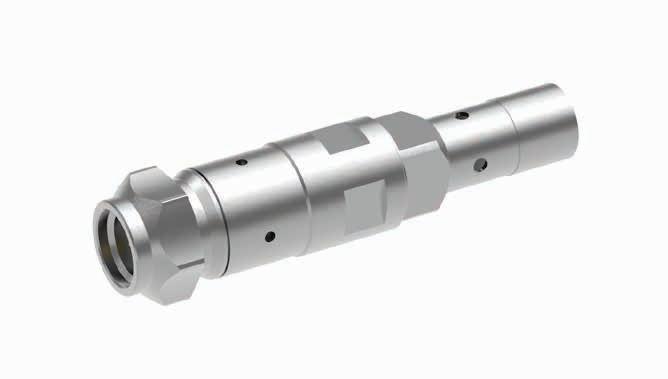
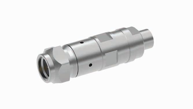
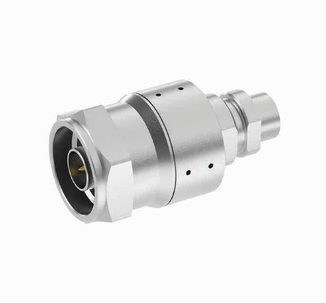
PLUGS
STRAIGHT PLUG SOLDER TYPE CABLE
CABLE GROUP
NUMBER SHF8 R163 068 L21
STRAIGHT PLUGS CRIMP TYPE
CABLE GROUP
EN4604-006WM
NUMBER
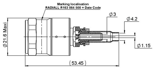
064 500 1
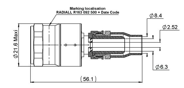
EN4604-007WN R163 092 500 2
STRAIGHT PLUG FULL CRIMP TYPE
CABLE GROUP PART NUMBER
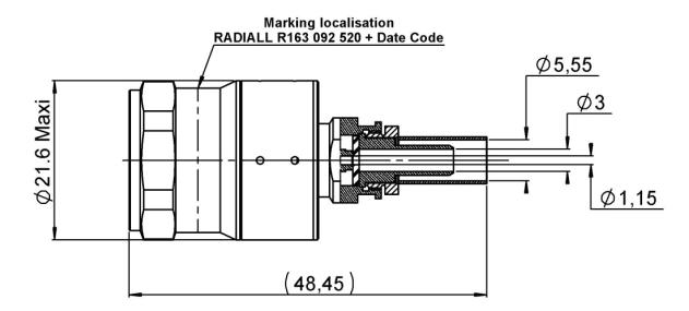
RG 142 FTX / RG 400 / KX 23 / RG 223 R163 092 520
N 18 GHZ/N 18 GHZ SELF-LOCK/TNC 18 GHZ/TNC 18 GHZ SELF-LOCK/SMA 2.9/SMA 2.9 SELF-LOCK/2.4 MM | 11-7 SIMPLIFICATION IS OUR INNOVATION Visit www.radiall.com for more information
PART
FIG. 1
FIG. 2
FIG.
PART
R163
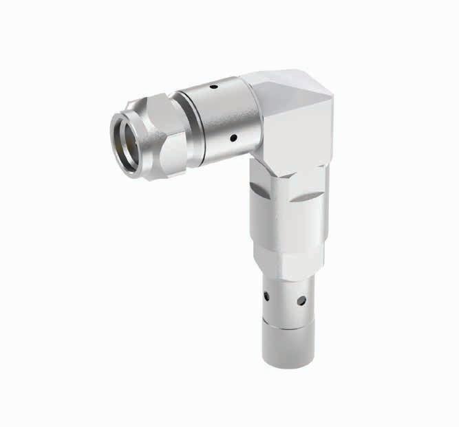
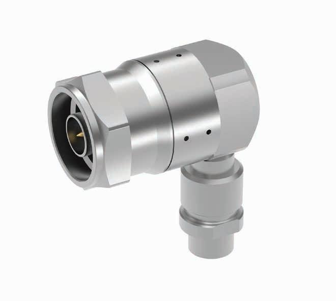
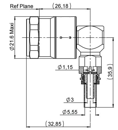
RIGHT ANGLE PLUG FULL CRIMP TYPE
CABLE GROUP
RG 142 FTX / RG 400 / KX 23 / RG 223
RIGHT ANGLE PLUG SOLDER TYPE CABLE
CABLE GROUP
PART NUMBER
R163 197 010
PART NUMBER SHF8
R163 198 L21
RIGHT ANGLE PLUG CRIMP TYPE
CABLE GROUP
EN 4604-007WN
PART NUMBER
R163 199 010
11-8 | N 18 GHZ/N 18 GHZ SELF-LOCK/TNC 18 GHZ/TNC 18 GHZ SELF-LOCK/SMA 2.9/SMA 2.9 SELF-LOCK/2.4 MM SIMPLIFICATION IS OUR INNOVATION Visit www.radiall.com for more information N 18 GHz Self-Lock
INTRODUCTION
TNC 18 connectors are 50 ohm precision TNC Type connectors designed to perform through 18 GHz� TNC connectors are a popular medium sized option commonly used in microwave and RF applications that require average power handling and good electrical performance. Radiall TNC connector interfaces utilizes a PTFE (Teflon) dielectric. The male connectors are provided with a 14 mm (9/16 in.) hex coupling nut so they can be properly torqued. Connector bodies are made from stainless steel, and contacts are made from gold plated and heat treated beryllium copper contacts to insure long life and reliability.
Radiall offers TNC connectors for semi-rigid and low loss flexible cables, receptacles and precision adapters�
Connectors for low loss flexible cables and TestPro cables are not detailed in this section. They are available in ourcable assembly offer.
INTERFACE
TNC 18 DESIGN FEATURES
• Excellent performance up to 18 GHz
• Low VSWR and insertion loss
• Rugged construction for reliability
• Superior interface environmental seal
• Medium power capability
N 18 GHZ/N 18 GHZ SELF-LOCK/TNC 18 GHZ/TNC 18 GHZ SELF-LOCK/SMA 2.9/SMA 2.9 SELF-LOCK/2.4 MM | 11-9 SIMPLIFICATION IS OUR INNOVATION Visit www.radiall.com for more information
TNC 18 GHz
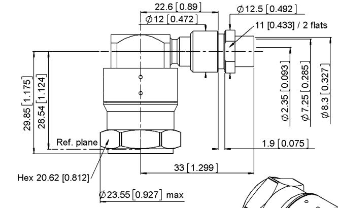
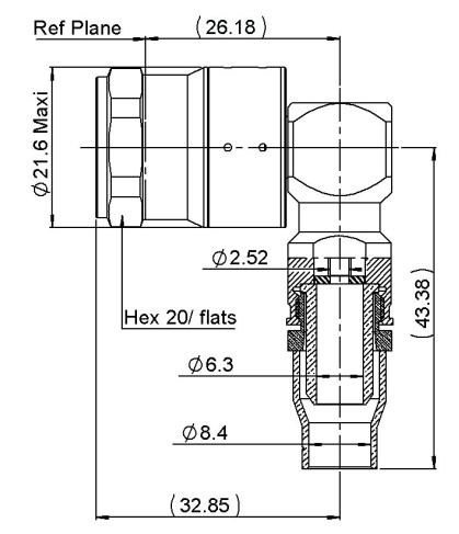
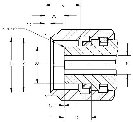
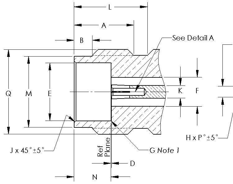
PLUG JACK LETTER MM INCH MIN MAX MIN MAX A 6 18 6 22 0 243 0 245 B 8 03 8 09 0 316 0 319 C 11 40 11 60 0 449 0 457 D 1 34 1 36 0 053 0 054 E 0� 35 0�65 0�014 0�026 F 1 62 1 66 0 064 0 065 G 5 28 5 32 0 208 0 210 1 5 � 28 5 � 38 0� 208 0� 212 2 5 35 5 50 0 211 0 217 3 -0 30 0 55 -0 012 0 022 4 0 35 0 90 0 014 0 065 LETTER MM INCH MIN MAX MIN MAX A 4 68 4 72 0 184 0 186 B 8 10 8 15 0 319 0 321 C 8 32 8 46 0 328 0 333 D 9 61 9 68 0 379 0 381 E 6 �93 6 �98 0� 273 0� 275 F 5 28 5 32 0 208 0 210 G 1 62 1 66 0 064 0 065 H 2 �14 2 �18 0�084 0�086 1 4 98 5 23 0 196 0 206 2 8 36 8 46 0 329 0 333 3 0 48 1 02 0 019 0 040 4 1 80 2 20 0 071 0 087 5 10 60 11 00 0 417 0 432 6 5 18 5 28 0 204 0 208 7 -0 10 0 05 0 004 0 002 8 5 20 5 70 0 204 0 224
CHARACTERISTICS
TEST / CHARACTERISTICS
ELECTRICAL CHARACTERISTICS
Impedance
MIL-C-39012 A
VALUES / REMARKS
MECHANICAL CHARACTERISTICS
Force: Not Applicable Torque: 1.96 inch pounds (22.6 N.cm) Recommended Mating Torque
22.98 inch pounds (265 N.cm) Proof Torque
Retention Force 3-24
Lbf (44.5 daN)
Lbf (227 N min) (cable dia. .189 (4.8) to .228 (5.8)) 76.4 Lbf (340 N min) (cable dia. .250 (6.35) and above)
Center Contact Retention - Axial: 6.06 Lbf (27 N)
ENVIRONMENTAL CHARACTERISTICS
Temperature Range
• Standard Models
• Hermetic Sealed Models
• Models for Semi-Rigid Cables
Combined Climate Tests
Thermal Shock
3-20
-65 °C / + 165 °C -65 °C / +100 °C -65 °C / +105 °C
MIL-STD-202, Method 107, Condition B
High Temperature Endurance - MIL-STD-202, Method 108
Corrosion (Salt Spray) 3-13
Vibrations 3-18
Shocks 3-19
Moisture Resistance 3-21
MATERIALS
MIL-STD-202, Method 101, Condition B
MIL-STD-202, Method 204, Condition B
MIL-STD-202, Method 213, Condition G
MIL-STD-202, Method 106
Low Pressure 3-22 Not Applicable
Hermetic SealApplied Vacuum 10 -6 mm of Hg (Torrs) Leakage Rate < 10 -6 atm/cm 3/s
Leakage - Pressure 3.5 bars; Duration 2 mn; Temperature 15 °C to 25 °C
Body - Stainless Steel
Center Socket Contact
• Male
• Female - Brass Bronze
Ferrules - Brass
Insulators - PTFE Teflon
Gaskets
PLATING
Silicone Elastomer
Body - Passivated Center Contacts
Gold Plated
11-10 | N 18 GHZ/N 18 GHZ SELF-LOCK/TNC 18 GHZ/TNC 18 GHZ SELF-LOCK/SMA 2.9/SMA 2.9 SELF-LOCK/2.4 MM SIMPLIFICATION IS OUR INNOVATION Visit www.radiall.com for more information TNC 18 GHz
- 50Ω Frequency Range - DC - 18 GHz
3-14 Semi–Rigid Cable:
max Flexible Cable:
12.4 GHz
Series Adapter:
max Insertion loss 3-27 0.18 dB max
9 GHz RF Leakage 3-26 -60 dB min from
GHz Insulation Resistance 3-11 5000
min Contact Resistance • Center Contact
• Outer Contact
3-16Initial 1 5 0 2 After Proof 2Working Voltage - At sea level: 500 V rms at 70000 ft (21000 m): 125 V rms Dielectric Withstanding Voltage 3-17 At sea level: 1500 V rms at 70000 ft (21000 m): 375 V rms RF
3-23 At sea level: 1000
MHz sine wave)
V.S.W.R.
1.17
1.35 at
In
1.35
at
2 to 3
MΩ
(mΩ)
(mΩ)
Withstanding Voltage
V rms (5
Durability 3-15 500
Axial
-
-
100
Matings Mating / Unmating
29.40 inch pounds (339 N.cm) Coupling Mechanism Retention Force 3-25
Cabling
51
--
-
-
PLUGS & JACKS
STRAIGHT PLUGS CRIMP TYPE FOR FLEXIBLE CABLE
CABLE GROUP CABLE GROUP DIA. PART
/ RG225
STRAIGHT PLUGS SOLDER TYPE FOR SEMI-RIGID CABLE RIGHT ANGLE PLUGS CRIMP TYPE FOR FLEXIBLE CABLE
GROUP
Notes
Standard packaging = unit All dimensions are given in mm (inch)
N 18 GHZ/N 18 GHZ SELF-LOCK/TNC 18 GHZ/TNC 18 GHZ SELF-LOCK/SMA 2.9/SMA 2.9 SELF-LOCK/2.4 MM | 11-11 SIMPLIFICATION IS OUR INNOVATION Visit www.radiall.com for more information TNC 18 GHz
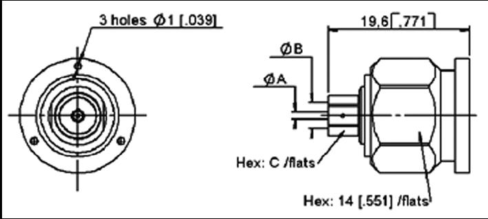
FIG. 1 FIG. 2
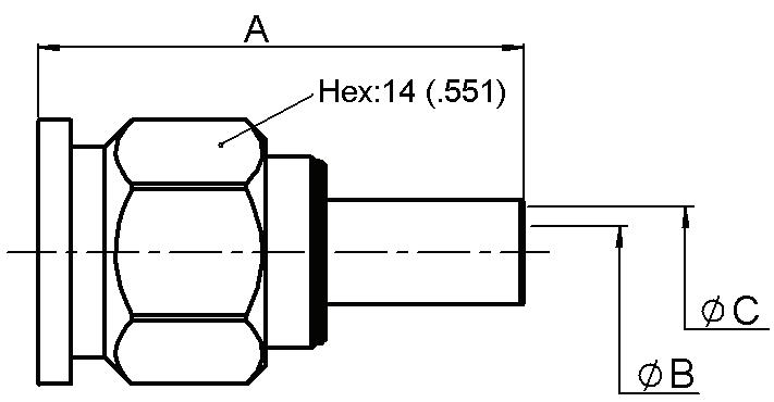
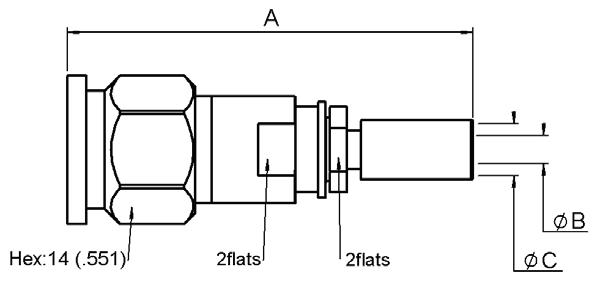
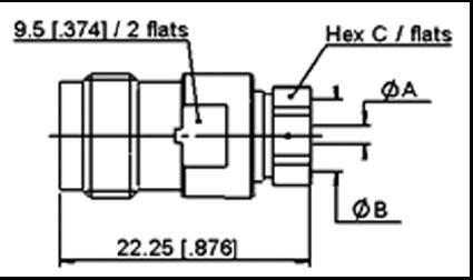
DIMENSIONS MM (INCH) NOTE A B C
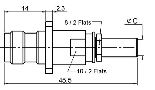
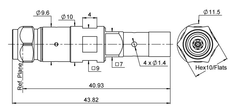
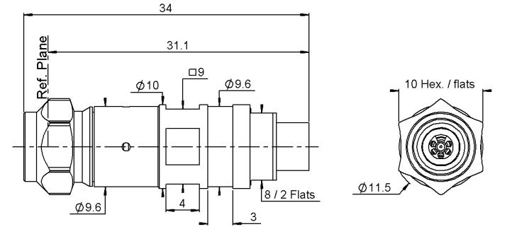
R143 082 700 1 30 (1.181) 3.2 (.126) 5.5 (.218) Incl. Heatshrink Tube R143 097 700 2 43.5 (1.713) 3 (.118) 5.5 (.218) - 3 85/50/S R143 088 101 47 (1.85) 3 (.118) 4.2 (.165) - 4 �13/50/S R143 093 700 43.5 (1.71) 2.7 (.106) 4.5 (.177) -
07/50/S R143 092 790 49.7 (1.957) 6.3 (.248) 8.4 (.331) RG214
R143 089 700 1 35 (1.38) 7.5 (.295) 11 (.433)CABLE
CABLE GROUP DIA. PART NUMBER DIMENSIONS MM (INCH) A B C RG402 141" R143 051 700 1 (.039) 3.65 (.144) 5 (.197) RG401 250" R143 054 700 1.7 (.067) 6.45 (.254) 8 (.315)
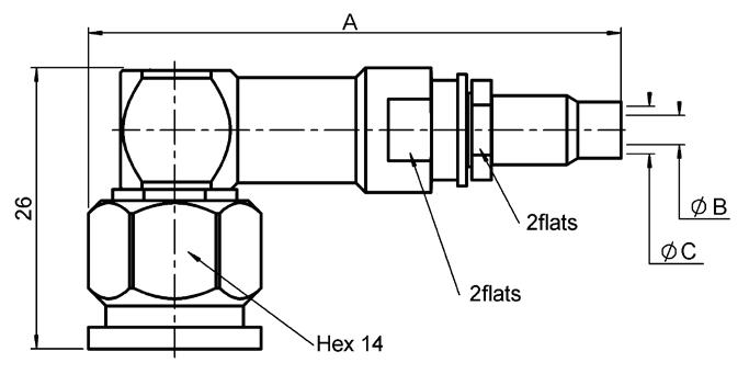
DIMENSIONS MM (INCH) NOTE A B C -
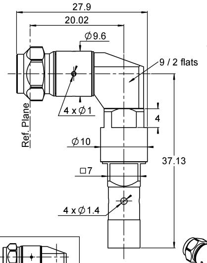
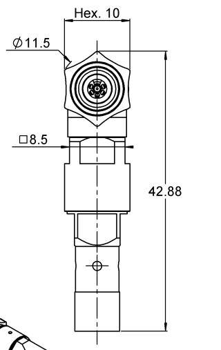
188 101 54.2 (2.13) 3 (.118) 4.2 (.165) Incl. Heatshrink Tube -
191 700 50 (1.97) 2.7 (.106) 4.5 (.177)
NUMBER FIG.
RG142 / RG223 / RG400 5/50/D
8
11/50/D
GROUP
CABLE
CABLE GROUP DIA. PART NUMBER
3 85/50/S R143
4 �13/50 R143
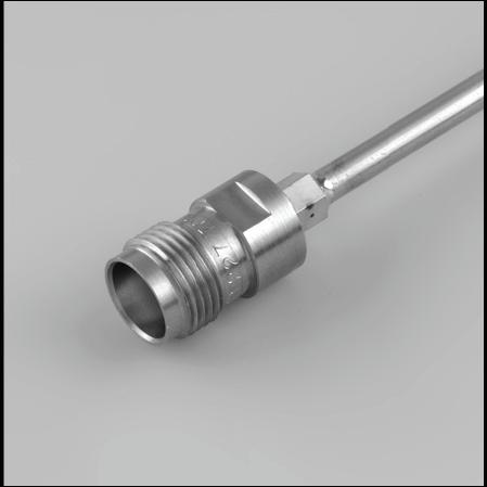
STRAIGHT JACK SOLDER TYPE FOR SEMI-RIGID CABLE
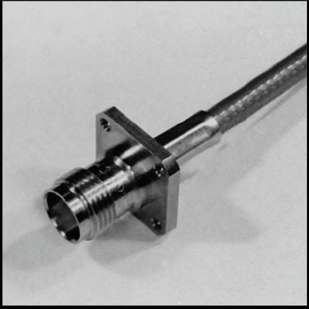
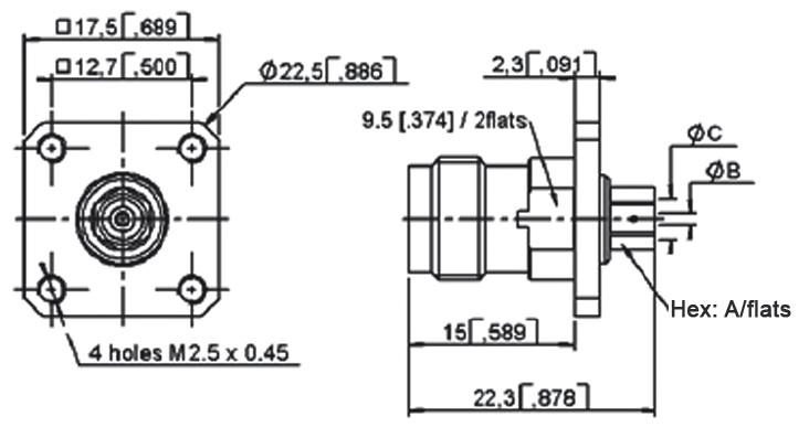
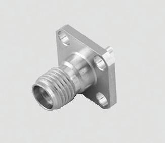
STRAIGHT SQUARE FLANGE JACK CRIMP TYPE FOR FLEXIBLE CABLE
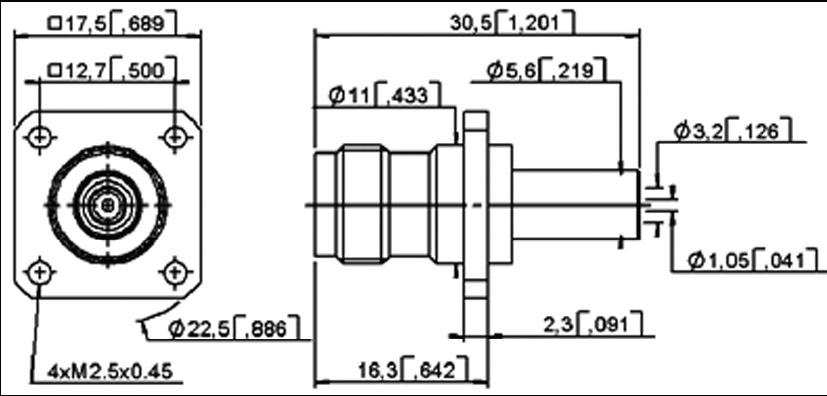
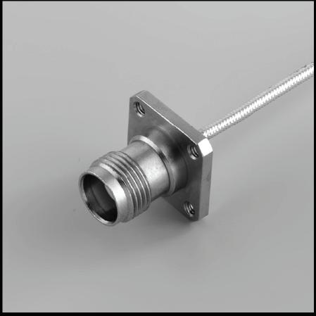
STRAIGHT SQUARE FLANGE JACKS SOLDER TYPE FOR SEMI-RIGID CABLE
11-12 | N 18 GHZ/N 18 GHZ SELF-LOCK/TNC 18 GHZ/TNC 18 GHZ SELF-LOCK/SMA 2.9/SMA 2.9 SELF-LOCK/2.4 MM SIMPLIFICATION IS OUR INNOVATION Visit www.radiall.com for more information TNC 18 GHz
FIG. 1
CABLE GROUP CABLE GROUP DIA. PART NUMBER FIG. C PANEL DRILLING NOTE - 4 13/50 R143 295 700 2 4.4 (.173) P01 Ind. Heatshrink Tube RG142 / RG223 / RG400 5/50/D R143 292 700 1 5.6 (.219) R143 297 700 2 CABLE GROUP CABLE GROUP DIA. PART NUMBER DIMENSIONS MM (INCH) PANEL DRILLING A B C RG405 085" R143 272 700 4 (.157) 0.6 (.024) 2.25 (.089) P12 RG402 �141" R143 273 700 5 (.197) 1 (.039) 3.65 (.144) RG401 250" R143 274 700 8 (.315) - 6.45 (.254) CABLE GROUP CABLE GROUP DIA. PART NUMBER DIMENSIONS MM (INCH) A B C RG402 141" R143 227 700 1 (.039) 3.65 (.143) 5 (.197)
FIG. 2
JACKS & RECEPTACLES
N 18 GHZ/N 18 GHZ SELF-LOCK/TNC 18 GHZ/TNC 18 GHZ SELF-LOCK/SMA 2.9/SMA 2.9 SELF-LOCK/2.4 MM | 11-13 SIMPLIFICATION IS OUR INNOVATION Visit www.radiall.com for more information TNC 18 GHz
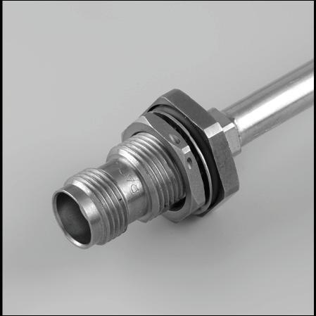
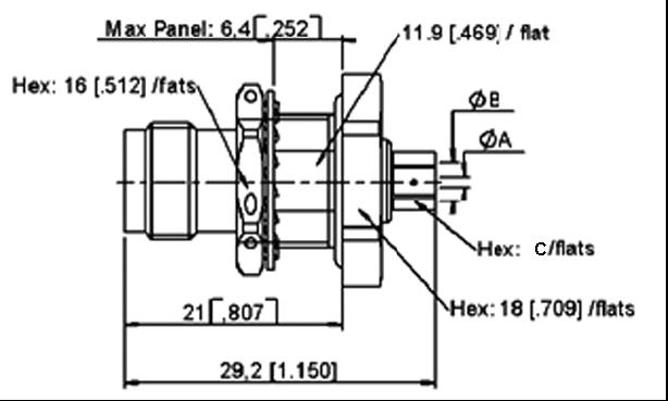
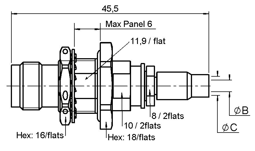
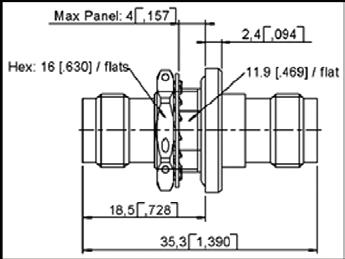
STRAIGHT BULKHEAD JACK PANEL SEALED
FIG. 1
CABLE GROUP CABLE GROUP DIA. PART NUMBER FIG. DIMENSIONS MM (INCH) PANEL DRILLING TYPE A B RG402 �141" R143 321 700 1 3.65 (.144) 5 (.197) P09 Solder RG401 250" R143 322 700 6 45 8 - 4 13/50 R143 340 700 2 2 7 4 5 Crimp
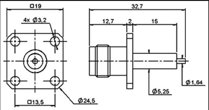
PART NUMBER CAPTIVE CENTER CONTACT PANEL DRILLING R143 412 700 Yes P13
FIG. 2
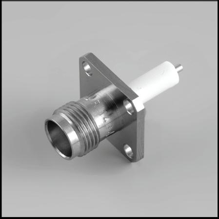
SQUARE FLANGE STRAIGHT FEMALE RECEPTACLE (EXTENDED DIELECTRIC)
ADAPTERS & CAPS
11-14 | N 18 GHZ/N 18 GHZ SELF-LOCK/TNC 18 GHZ/TNC 18 GHZ SELF-LOCK/SMA 2.9/SMA 2.9 SELF-LOCK/2.4 MM SIMPLIFICATION IS OUR INNOVATION Visit www.radiall.com for more information TNC 18 GHz
IN SERIES ADAPTERS
FIG. 1
FIG. 2
FIG. 3
FIG. 4
CAPS PART NUMBER NOTE R143 850 700 Male Short Circuit PART NUMBER FIG. CAPTIVE CENTER CONTACT PANEL DRILLING NOTE
700 1 Yes - Male - Male R143
- Female - Female R143
- Male
Female
P16 Square Flange Female
P09 Bulkhead
FIG. 5
R143 703
704 700 2
705 700 3
-
R143 710 700 4
- Female R143 730 700 5
Panel Sealed Female - Female
TNC 18 GHz Self-Lock
INTRODUCTION
Radiall introduces a new innovative technology in response to market demands to eliminate locking wires
Radiall’s Self-Lock RF connectors are the perfect solution to provide secure connection-facing vibrations experienced in aerospace applications.
The Self-Locking design is intended to eliminate the need for safety wires and saves many hours, the locking feature is achieved via a spring loaded, corrugated washer
Self-Lock connectors are intermatable with any standard jack or female receptacle; there is no change in performance All electrical, mechanical and environmental specifications are preserved. With this solution, matingunmating becomes faster, safer (no forgotten lock wire) and is proven to be more robust even in the harsh environment of an airplane bilge.
The Self-Lock connectors can be provided on any compatible cable size. The innovative crimp system attachment offers the opportunity for on-site assembly as well as ordering finished cable assemblies.
FEATURES & BENEFITS
• No locking wire
• Secure connection in harsh environments
• Easy and fast to install
• Self-Lock plugs compatible with standard jacks and receptacles
N 18 GHZ/N 18 GHZ SELF-LOCK/TNC 18 GHZ/TNC 18 GHZ SELF-LOCK/SMA 2.9/SMA 2.9 SELF-LOCK/2.4 MM | 11-15 SIMPLIFICATION IS OUR INNOVATION Visit www.radiall.com for more information
TNC 18 GHz Self-Lock
PLUGS
STRAIGHT PLUG SOLDER TYPE CABLE
CABLE GROUP
NUMBER SHF8 R143 068 L21
RIGHT ANGLE PLUG SOLDER TYPE CABLE
CABLE GROUP
NUMBER
SHF8 R143 198 L21
11-16 | N 18 GHZ/N 18 GHZ SELF-LOCK/TNC 18 GHZ/TNC 18 GHZ SELF-LOCK/SMA 2.9/SMA 2.9 SELF-LOCK/2.4 MM SIMPLIFICATION IS OUR INNOVATION Visit www.radiall.com for more information
PART
PART
INTRODUCTION
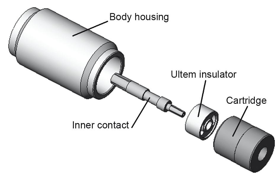
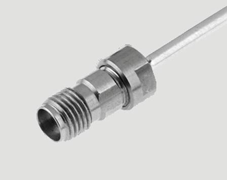
SMA 2.9 series is compatible with K® series, 2�92 mm, SMA and SMA 3�5 series, and has a shortened male center contact, ensuring a non destructive mating. Radiall offers four product variations for SMA 2.9 to meet all your needs with two different designs. The standard design is using our “ULTEM” insulator technology and is qualified up to 40 GHz. The high frequency design is using our “KAPTON” insulator technology and is qualified up to 46 GHz. All versions feature the same electrical high performance and are available in a variety of configurations.
SMA 2.9 FOR GENERAL USE, “ULTEM” TECHNOLOGY, DC-40 GHZ
This robust design is suitable for most applications. The ULTEM insulator provides a high ingress protection level against chemicals, fluids or dust and is well suited for high frequency aerospace and military equipment.
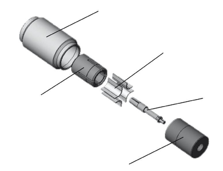
SMA 2.9 FOR TEST LABORATORY USE, “KAPTON” TECHNOLOGY, DC-46 GHZ
The KAPTON insulator design is excellent for high frequency measurements in test laboratories. KAPTON is also very stable with temperature. Radiall SMA 2.9 adapters using KAPTON are specified DC-46 GHz and operate within a large temperature range - 65 °C/+200 °C
SMA 2.9 FOR SPACE APPLICATIONS
Radiall is a certified manufacturer of connectors for space applications according to ESA specifications. A range of space qualified SMA 2.9 connectors using the ULTEM insulator technology is available. Please consult us.
SMA 2.9 FOR HARSH ENVIRONMENTS
Radiall also offers a range of cable assemblies equipped with specific connectors for applications in harsh environment. The connectors are made of high grade stainless steel 316L ultra resistant to corrosion and wear Please consult us
N 18 GHZ/N 18 GHZ SELF-LOCK/TNC 18 GHZ/TNC 18 GHZ SELF-LOCK/SMA 2.9/SMA 2.9 SELF-LOCK/2.4 MM | 11-17 SIMPLIFICATION IS OUR INNOVATION Visit www.radiall.com for more information
SMA 2.9
3D VIEW OF SMA 2.9 “ULTEM” DESIGN
3D VIEW OF SMA 2.9 “KAPTON” DESIGN
Bodyhousing
Innercontac Slottedt holder Cartridge
KaptonStrips
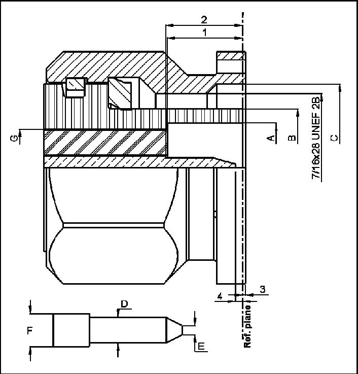
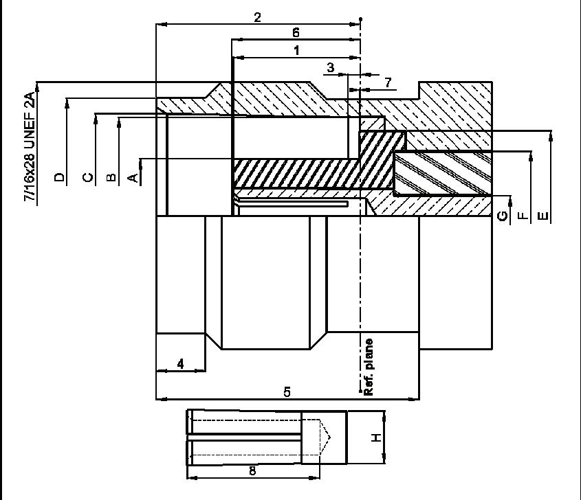
INTERFACE
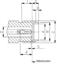
1 2 87 3 27 113 129
2 1 88 1 98 074 078
3 0 65 0 95 026 037
4 2 � 40 2 �68 �094 �105
5 - 0 08 - 003
A 4 60 4 63 181 182
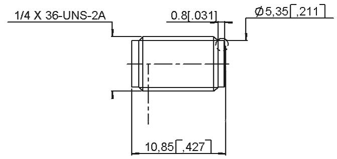
B 5 � 30 5 � 35 � 209 � 211 C 1/4 - 36 UNS 2A
D 2 90 2 94 114 116
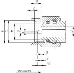
OR FIGURE MM INCH
6 2 63 3 25 103 128 7 0 90 1 10 35 043 8 - 0 08 - 003 9 0� 49 0�78 �019 �031 10 1 22 1 40 048 055
1/4 - 36 UNS 2B
2 �90 2 �94 �114 �116
6 60 6 70 260 264
4 55 4 58 179 180 G 0 92 0 94 036 037 H 0 20 0 34 008 013
11-18 | N 18 GHZ/N 18 GHZ SELF-LOCK/TNC 18 GHZ/TNC 18 GHZ SELF-LOCK/SMA 2.9/SMA 2.9 SELF-LOCK/2.4 MM SIMPLIFICATION IS OUR INNOVATION Visit www.radiall.com for more information SMA 2.9
MIN MAX MIN MAX
PLUG JACK LETTER OR FIGURE MM INCH
MIN MAX MIN MAX
C
D
LETTER
E
F
CHARACTERISTICS SMA 2.9
TEST / CHARACTERISTICS
ELECTRICAL CHARACTERISTICS
VALUES / REMARKS
ULTEM TECHNOLOGY KAPTON TECHNOLOGY
Impedance 50Ω
Frequency Range
V.S.W.R. < 1.05 + 0.005 F (GHz)
Insertion Loss 0.03 √ F (GHz)
RF Leakage
Insulation Resistance
Contact Resistance
• Outer Contact • Inner Contact
90 dB max
5000 MΩ
2 mΩ
≤ 3 mΩ Hermetic ≤ 7 mΩ
Voltage Rating 350 V(RMS)
Dielectric Withstanding Voltage 750 V(RMS)
MECHANICAL CHARACTERISTICS
Mechanical Endurance 500 Matings Force to Engage and Disengage ≤ 23 N cm (2 in/lbs)
Mating Torque 80 to 115 N cm (7 to 10 in/lbs)
Coupling Nut Retention Force ≤ 272 N (61 lbf)
Cable Retention Force • .085"
.141"
N (30 lbf)
N (60 lbf)
Contact Captivation 28N (6.3 lbf)
ENVIRONMENTAL CHARACTERISTICS
Temperature Range
Thermal Shock MIL STD 202, Method 107, Condition B
High Temperature Test MIL STD 202, Method 108
Corrosion (Salt Spray)
MIL STD 202, Method 101, Condition B, 5 %
Vibration MIL STD 202, Method 204, Condition D, 20g Shock MIL STD 202, Method 213, Condition I, 100g
Moisture Resistance MIL STD 202, Method 106
MATERIALS AND PLATING
Bodies
Center Contacts
Gasket
Material
Plating
Stainless Steel Passivated
Beryllium Copper Gold Plated
Silicone RubberInsulators
Ultem (Ultem Technology) Kapton (Kapton Technology) -
Notes
Packaging: unit
All dimensions are given in mm (inch)
N 18 GHZ/N 18 GHZ SELF-LOCK/TNC 18 GHZ/TNC 18 GHZ SELF-LOCK/SMA 2.9/SMA 2.9 SELF-LOCK/2.4 MM | 11-19 SIMPLIFICATION IS OUR INNOVATION Visit www.radiall.com for more information
DC
GHz DC
GHz
- 40
- 46
–
≥
≤
Straight
135
•
270
-65 °C / + 165 °C -65 °C
+200 °C
/
PLUGS
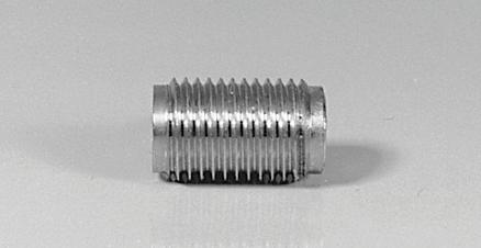
STRAIGHT PLUGS, SOLDER TYPE FOR MICROPOROUS SEMI-RIGID CABLES

JACKS & RECEPTACLES
STRAIGHT JACK SOLDER TYPE FOR MICROPOROUS SEMI-RIGID CABLES
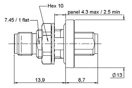
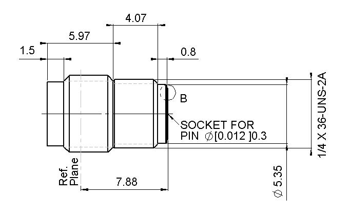
UNIVERSAL SCREW-ON FEMALE RECEPTACLES
11-20 | N 18 GHZ/N 18 GHZ SELF-LOCK/TNC 18 GHZ/TNC 18 GHZ SELF-LOCK/SMA 2.9/SMA 2.9 SELF-LOCK/2.4 MM SIMPLIFICATION IS OUR INNOVATION Visit www.radiall.com for more information SMA 2.9
CABLE GROUP CABLE GROUP DIA. PART NUMBER INSULATOR DIMENSION A (MM) CAPTIVE CENTER CONTACT FREQUENCY RANGE RG405 085" Microporous R127 800 001 ULTEM 2 25 Yes DC - 40 GHz RG402 141" Microporous R127 800 101 3 66 RG405 085" Microporous R127 052 001 KAPTON 2 2 DC - 46 GHz - 116" Microporous R127 055 001 3 0 CABLE GROUP CABLE GROUP DIA. PART NUMBER INSULATOR DIMENSION A (MM) CAPTIVE CENTER CONTACT FREQUENCY RANGE RG405 085" Microporous R127 820 001 ULTEM 2 25 Yes DC - 40 GHz PART NUMBER INSULATOR FREQUENCY RANGE USED WITH GLASS BEAD FOR PIN DIAMETER R127 841 001 ULTEM DC - 40 GHz R280 760 040 0.3 (.012) R127 601 001 KAPTON DC - 46 GHz R127 601 421 R280 760 000 Included
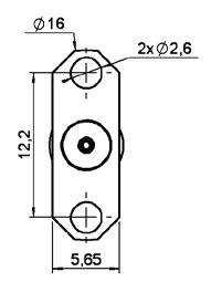
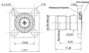
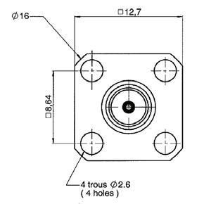
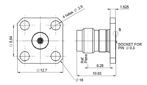
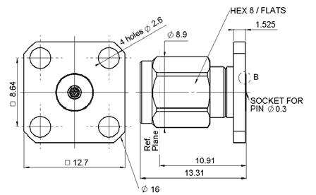
FLANGE FEMALE RECEPTACLES
R127 840 021 1
R127 842 001 2
R127 631 001
R127 632 001 3
R127 842 101 4 PEEK
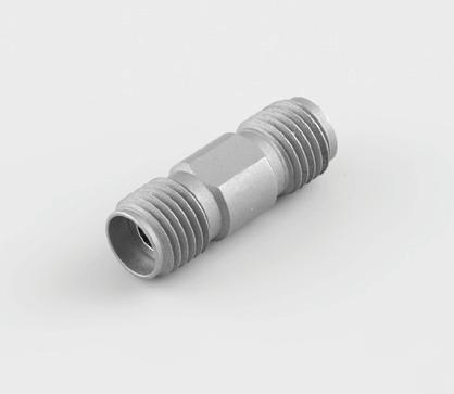
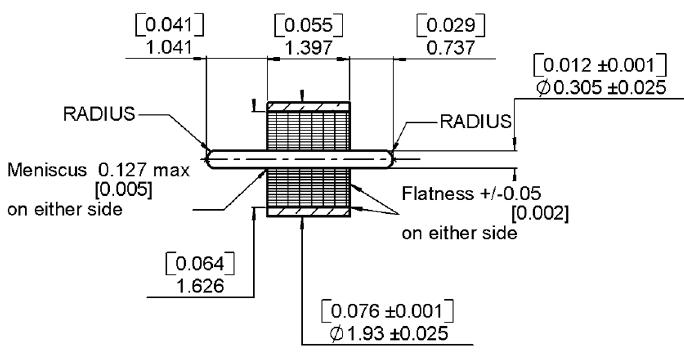
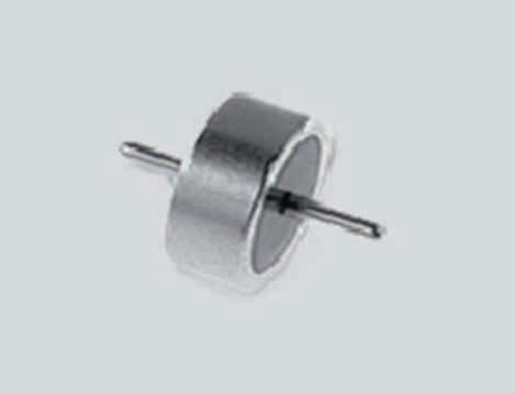
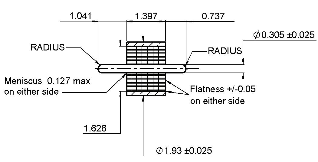
GLASS BEAD & IN SERIES ADAPTERS
(.012) Panel Leakage IP67
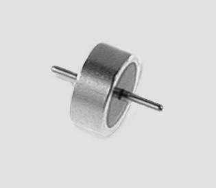
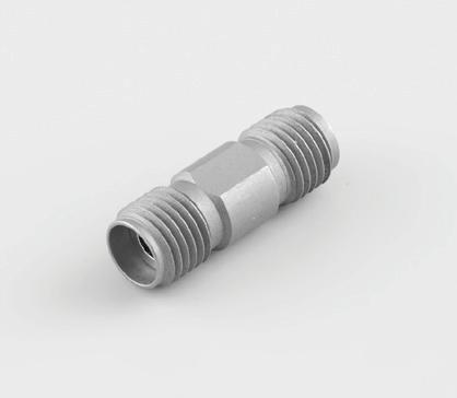
GLASS BEAD IN SERIES ADAPTERS
R127 703 001 2
R127 704 001 3
R127 705 001 1
R127 712 001 4
R127 732 100 5
R127 753 000 5
R127 870 001 1
R127 872 001 3
Male- Male
Female- Male
Female- Female
Female - Female - 4 Hole Flange
Female - Female - Bulkhead Panel Sealed
Female - Female - Bulkhead Hermetic
Female- Female
Female- Male
R127 871 001 2 Male- Male
N 18 GHZ/N 18 GHZ SELF-LOCK/TNC 18 GHZ/TNC 18 GHZ SELF-LOCK/SMA 2.9/SMA 2.9 SELF-LOCK/2.4 MM | 11-21 SIMPLIFICATION IS OUR INNOVATION Visit www.radiall.com for more information SMA 2.9
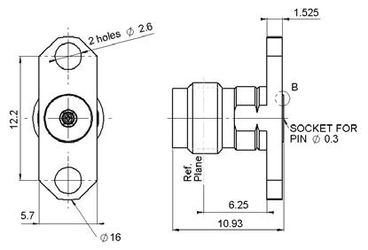
PART NUMBER FIG. INSULATOR CAPTIVE CENTER CONTACT PANEL DRILLING USED WITH GLASS BEAD NOTE
ULTEM Yes P02 N/A
With Cylindrical Center Contact
P01
R280 760 040 Accept Pin Dia 0.3 (.012)
-
KAPTON
- -
P01
Accept Pin Dia 0.3
FIG. 1
FIG. 2
FIG. 3
FIG. 4
PART NUMBER PACKAGING R280 760 040 100 PART NUMBER FIG. INSULATOR NOTE FREQUENCY RANGE
KAPTON
DC - 46 GHz
ULTEM
DC - 40 GHz
FIG. 1 FIG. 2 FIG. 3
FIG. 4
FIG. 5
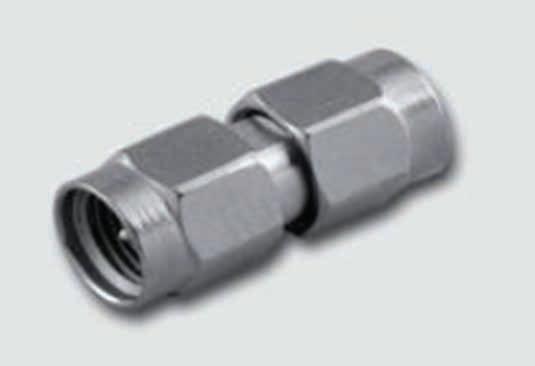
BETWEEN SERIES ADAPTERS
BETWEEN SERIES ADAPTERS [1]
970 091 4
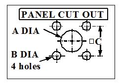
PANEL DRILLING
mminc h maximinimaximini
A1.631.6 0.064.063
B2.702.6 0.106.102
C8.698.5 9.342.338 mminch maximinimaximini
Notes
A2.952.91.116.115 B2.72.6.106.102
11-22 | N 18 GHZ/N 18 GHZ SELF-LOCK/TNC 18 GHZ/TNC 18 GHZ SELF-LOCK/SMA 2.9/SMA 2.9 SELF-LOCK/2.4 MM SIMPLIFICATION IS OUR INNOVATION Visit www.radiall.com for more information SMA 2.9
PART NUMBER FIG. INSULATOR NOTE FREQUENCY RANGE R191
1 KAPTON SMA 2 9 Male - SMA 2 4 Male DC - 46 GHz R191
2 SMA 2 9 Male - SMA 2 4 Female R191
SMA 2 9 Female - SMA 2 4 Male R191
SMA 2 9 Female - SMA 2 4 Female
970 061
970 071
970 081 3
FIG. 1 FIG. 2
FIG. 3 FIG. 4
to reach 46 GHz within a temperature range of – 65 °C/+ 200 °C.
1. These adapters are still using the previous technology (4 kapton strips) allowing
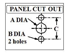
P01 P02
C8
34
8
.698.59.
2.33
SMA 2.9 Self-Lock
CHARACTERISTICS
TEST / CHARACTERISTICS
ELECTRICAL CHARACTERISTICS
VALUES / REMARKS
Impedance 50Ω
Frequency Range
V.S.W.R.
DC - 46 GHz
< 1.05 + 0.005 F (GHz)
Insertion Loss (Typ) dB 0.03 √ F (GHz) dB
RF Leakage (Min) dB -90 dB max
Insulation Resistance ≥ 5 GΩ
Contact Resistance
MECHANICAL CHARACTERISTICS
CC : ≤ 7 MΩ
OC : ≤ 3 MΩ
Durability 500 Cycles Force to Engage and Disengage 6.5 N Max
Cable Retention Force 141: 270 N
ENVIRONMENTAL CHARACTERISTICS
Temperature Range -65 °C to +165 °C
Thermal Cycling MIL STD 202 Method 107 Condition B
Vibration MIL STD 202 Method 214A Cond D 20G
Shock MIL STD 202 Method 213 Cond I, 100g
Moisture Resistance MIL STD 202 Method 106
Corrosion MIL STD 202 Method 101 Cond B, 5%
11-24 | N 18 GHZ/N 18 GHZ SELF-LOCK/TNC 18 GHZ/TNC 18 GHZ SELF-LOCK/SMA 2.9/SMA 2.9 SELF-LOCK/2.4 MM SIMPLIFICATION IS OUR INNOVATION Visit www.radiall.com for more information
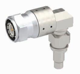
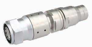
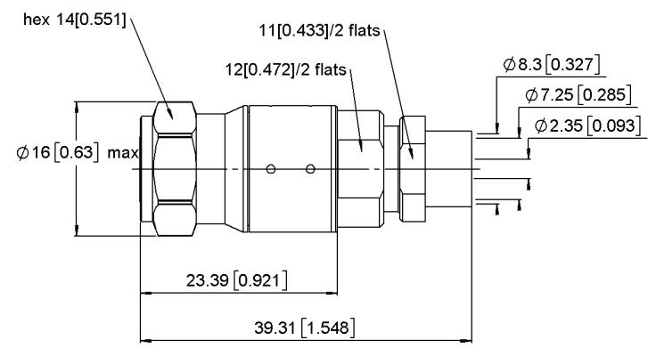
PLUGS
STRAIGHT PLUG SOLDER TYPE CABLE
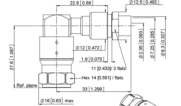
RIGHT ANGLE SOLDER TYPE CABLE
N 18 GHZ/N 18 GHZ SELF-LOCK/TNC 18 GHZ/TNC 18 GHZ SELF-LOCK/SMA 2.9/SMA 2.9 SELF-LOCK/2.4 MM | 11-25 SIMPLIFICATION IS OUR INNOVATION Visit www.radiall.com for more information
SMA 2.9 Self-Lock
FIG. 1
CABLE GROUP PART NUMBER FIG. SHF3UF R127 017 101 1 SHF4 6M R127 017 111 2
PART
R127
FIG. 2
CABLE GROUP
NUMBER SHF3UF
197 101
mm
INTRODUCTION
2�4 mm connectors are 50 ohm precision connectors designed for use to 50 GHz� The design eliminates the fragility of the SMA and 2.92 mm connectors by increasing the outer wall thickness and strengthening the female fingers. The outer conductor measures 2.4 mm and the robust wall of the connector body is designed to engage before the center conductor, assuring a rugged, repeatable mating interface. The male connectors are provided with a 8 mm (5/16 in.) hex coupling nut so they can be properly torqued.
2.4 mm connectors are mechanically compatible with 1.85 mm connectors. They cannot mate with SMA, 3.5-mm and 2 92-mm without the use of precision adapters
Radiall offers 2.4 mm connectors for semi-rigid and low loss flexible cables, receptacles, and precision adapters�
Connectors for low loss flexible cables and TestPro cables are not detailed in this section. They are available in our cable assembly offer.
INTERFACE
2.4 MM DESIGN FEATURES
• Excellent performance up to 50 GHz
• Low VSWR and insertion loss
• Rugged construction for reliability
• Mechanically compatible with 1�85 mm connector series
11-26 | N 18 GHZ/N 18 GHZ SELF-LOCK/TNC 18 GHZ/TNC 18 GHZ SELF-LOCK/SMA 2.9/SMA 2.9 SELF-LOCK/2.4 MM SIMPLIFICATION IS OUR INNOVATION Visit www.radiall.com for more information
2.4
LETTER MM INCH MIN MAX MIN A 4 8000 5 0600 0 1890 B
0 0539 D
E
F
K
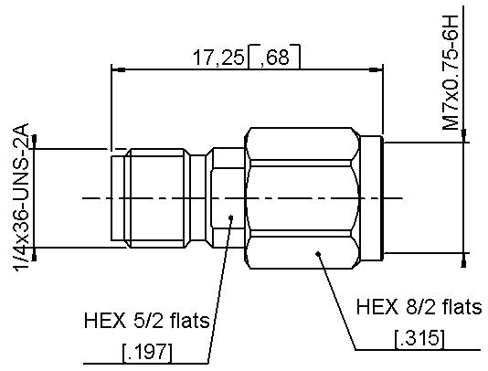
L 6 0000 - 0 2362 M 5 �7900 5 � 8900 0� 2280 N 3 0000 3 1000 0 1181 Q M7x0.75-6G LETTER MM INCH MIN MAX MIN A 1 8500
4500 0 0728 B
6600
C
D
R
PLUG JACK
1 3700 1 6300
0 0000 0 0760 0 0000
4 7700 4 7950 0 1878
2 3875 2 4125 0 0940
1 0290 1 0540 0 0405
2
4 3400 4
0 1709
0 0000 0 0760 0 0000
3 3800 3 4800 0 1331 L 7 0100 7 1100 0 2760 M 4 7250 4 7500 0 1860 N 2 3875 2 4125 0 0940 Q 0� 5100 0�7700 0�0201
M7x0.75-6H
2.4 mm
CHARACTERISTICS
TEST / CHARACTERISTICS
ELECTRICAL CHARACTERISTICS
Impedance
Frequency Range
V.S.W.R.
VALUES / REMARKS
50Ω
DC - 50 GHz
< 1.05 + 0.003 F (GHz)
Insertion Loss 0.04 √ F (GHz)
RF Leakage – 100 dB max
Insulation Resistance
• Contact Resistance <= 1400Veff > 5000 mΩ
Contact Resistance
• Outer Conductor
• Inner Conductor < 0.8 mΩ < 4 mΩ
Voltage Rating 250 V(RMS)
Dielectric Withstanding Voltage 500 V(RMS)
MECHANICAL CHARACTERISTICS
Mechanical Endurance
500 Matings Force to Engage and Disengage < 23 N cm
Mating Torque 90 N cm
Coupling Nut Retention Force < 272 N
Cable Retention Force
• Outer Conductor
• Inner Conductor 130 N
Contact Captivation 27N
ENVIRONMENTAL CHARACTERISTICS
Temperature Range -65 °C / + 165 °C
Thermal Shock
High Temperature Test
Corrosion (Salt Spray)
MIL STD 202, Method 107, Condition B, -65 °C / + 165 °C
MIL STD 202, Method 108, Condition D, 1000 H at 150 °C
MIL STD 202, Method 101, Condition B, 48 H / 35 °C / 5 %
Vibration MIL STD 202, Method 204, Condition H, 30g RMS Shock MIL STD 202, Method 213, Condition I, 100g
Moisture Resistance
MATERIALS AND PLATING
Bodies
MIL STD 202, Method 106, 80% / 100% 25 °C / 65 °C 10 Cycles
Material
Beryllium Copper
Plating
Cu2 � 5 Au0� 8
Outer Contact (Body Insert) Brass Cu2 5 Au0 8
Center Contacts
Beryllium Copper Ni2 Au1 3
Coupling Nut Stainless Steel Passivated Gaskets
Silicone RubberInsulators PEEK -
N 18 GHZ/N 18 GHZ SELF-LOCK/TNC 18 GHZ/TNC 18 GHZ SELF-LOCK/SMA 2.9/SMA 2.9 SELF-LOCK/2.4 MM | 11-27 SIMPLIFICATION IS OUR INNOVATION Visit www.radiall.com for more information
2.4 mm
PLUGS, JACKS & RECEPTACLES
STRAIGHT PLUGS, SOLDER TYPE FOR SEMI-RIGID CABLES
RG405 085" Microporous
STRAIGHT JACKS, SOLDER TYPE FOR SEMI-RIGID CABLES
1
052 000
052 202
2
UNIVERSAL SCREW-ON FEMALE RECEPTACLES
11-28 | N 18 GHZ/N 18 GHZ SELF-LOCK/TNC 18 GHZ/TNC 18 GHZ SELF-LOCK/SMA 2.9/SMA 2.9 SELF-LOCK/2.4 MM SIMPLIFICATION IS OUR INNOVATION Visit www.radiall.com for more information
CABLE
CABLE GROUP DIA. PART NUMBER CAPTIVE CENTER CONTACT
R327
CABLE
CABLE GROUP DIA. FIG. PART NUMBER CAPTIVE CENTER CONTACT
085" 1 R327 222 000 Yes �085"
R327 222 200 085" 2 R327 316 000 085" Microporous R327 316 010 PART NUMBER USING WITH GLASS BEAD FOR PIN DIAMETER R327 556 000 R280 760 040 0.3 (0.12)
GROUP
RG405 �085"
Yes
R327
GROUP
RG405
Microporous
FIG.
FIG.
N 18 GHZ/N 18 GHZ SELF-LOCK/TNC 18 GHZ/TNC 18 GHZ SELF-LOCK/SMA 2.9/SMA 2.9 SELF-LOCK/2.4 MM | 11-29 SIMPLIFICATION IS OUR INNOVATION Visit www.radiall.com for more information
PART NUMBER FIG. CAPTIVE CENTER CONTACT PANEL DRILLING USE WITH GLASS BEAD FOR PIN DIAMETER R327 430 000 1 Yes P01 R280 760 040 0.3 (0.12) R327 411 000 2 R327 465
P02
2.4 mm
000 3
FLANGE RECEPTACLES
FIG. 1
PART NUMBER PACKAGING R280 760 040 100
FIG. 2 FIG. 3
GLASS BEAD
IN SERIES ADAPTERS
DRILLING
11-30 | N 18 GHZ/N 18 GHZ SELF-LOCK/TNC 18 GHZ/TNC 18 GHZ SELF-LOCK/SMA 2.9/SMA 2.9 SELF-LOCK/2.4 MM SIMPLIFICATION IS OUR INNOVATION Visit www.radiall.com for more information
2.4 mm
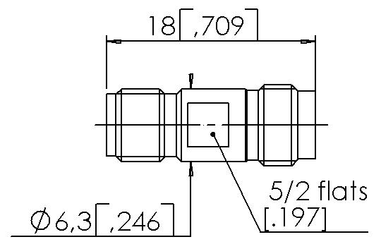
PART NUMBER FIG. FOR PIN DIAMETER R327 703 000 1 Male / Male R327 704 000 2 Male / Female R327 705 000 3 Female / Female R327 771 000 4 Male / Female Right Angle
FIG. 1
FIG. 2
P01 P02 LETTER MM INCH MIN MAX MIN MAX A 1 63 1 60 0 064 0 063 B 2 70 2 60 0 106 0 102 C 8 69 8 59 0 342 0 338
FIG. 3 FIG. 4 PANEL