


Section 5 Table of Contents
SUBMINIATURE SERIES
SPnT up to 40 GHz: R591 Series 5-2 to 5-4
R591 Series Electrical Schematics������������������������ 5-5 to 5-7
USB SERIES
SPnT USB up to 40 GHz: R57xxxxx01 Series (Terminated and Non-Terminated) 5-8 to 5-13
RAMSES SERIES
SPnT up to 50 GHz: R57x Series (Terminated and Non-Terminated) ������������������5-14 to 5-25
SPnT up to 12 4 GHz: R57x Series (N, BNC and TNC models)
5-26 to 5-30
RF Connector Allocation for SPnT Series 5-31 to 5-32
SPNT
ACCESSORIES SPNT & ELECTRICAL SCHEMATICS
Coaxial SPnT - Accessories 5-33 to 5-37
Coaxial SPnT - Electrical Schematics��������������� 5-38 to 5-43
TITANIUM SERIES
High Performance Multiport Switches
SPnT up to 40GHz: R51x Series 5-44 to 5-50
PLATINUM SERIES
High Performance Multiport Switches - SPnT Terminated Up to 40 GHz: R594 Series ������������������������������� 5-52 to 5-58
OPTIONAL FEATURES
Optional Features 5-59
Notes
Example of P/N: R591703400 is a SP4T SMA up to 26.5 GHz, normally open, 28 Vdc, without option, solder pins. 1. For part number creation and available options, see detailed part number selection for each series.
driver compatible Solder pins D-Sub connector Mini USB Micro-D connector HE 10 receptacle Certificate of conformity Calibration certificate Calibration certificate + RF curves
Subminiature Series
SUBMINIATURE SPNT UP TO 40 GHz
SMA – SMA 2.9 - QMA


Radiall's R591 coaxial subminiature switches have a typical operating life exceeding 25 million cycles; Providing excellent RF performance, repeatability, and a guaranteed life of 10 million cycles, which makes switches ideal for Automated Test Equipment (ATE) and other measurement applications. These subminiature switches are also an excellent choice for Mil/ Aero applications due to their small size, light weight, and outstanding shock and vibration handling capabilities.
Example of P/N: R591302420 is a SP4T SMA up to 6 GHz, normally open, 12 Vdc with TTL driver and solder pins.
PART NUMBER SELECTION
SERIES PREFIX
RF CONNECTORS
3: SMA up to 6 GHz
7: SMA up to 26 5 GHz
8: SMA 2 9 up to 40 GHz [6]
E: QMA up to 6 GHz [5]
TYPE
0: Normally open
2: Latching, global reset
6: Latching, separated reset [1]
ACTUATOR VOLTAGE
2: 12 Vdc
3: 28 Vdc
NUMBER OF POSITIONS
4: 4 positions
6: 6 positions
OPTIONS
0: Without option
1: Positive common
2: With TTL driver [2, 3 & 4]
3: With suppression diodes
4: With suppression diodes and positive common
ACTUATOR TERMINALS
0: Solder pins
5: Micro-D connector
Notes
1. Available with “solder pins“ models only.
2. Polarity is not relevant to application for switches with TTL driver.
3. Suppression diodes are already included with TTL option.
4. Available with “normally open” models only.
5. The QLF tradermark (Quick Lock Formula®) standard applies to QMA and QN series and guaranties the full intermateability between suppliers using this tradermark. Using QLF certified connectors also guarantees the specified level of RF performance.
6. Connector SMA2.9 is equivalent to "K connector ®", registered trademark of Anritsu.

Subminiature Series
GENERAL SPECIFICATIONS
Connectors SMA - QMA - SMA 2 �9
Actuator terminals
Solder Pins: double row connector for wrapping, soldering (250 ºC max / 30 sec), or connecting to 2.54 mm pitch female connector. 9 pin micro-D receptacle M83513/07-A according to MIL-C-85513.
Operating temperature range -40 ºC to +85 ºC
Storage temperature range -55 ºC to +85 ºC
Sine vibration
(According to MIL STD 202, Method 204D, Cond. D) 10 - 2,000 Hz, 20 g - operating
Random vibration
(According to MIL STD 202, Method 214A, Profile I, Cond. F) 50 - 2,000 Hz, 20.71 g - operating
Shock
(According to MIL STD 202, Method 213B, Cond. C) 100 g / 6 ms, 1/2 sine - operating
RF PERFORMANCE
Notes
See page 5-4 for typical RF performance.
Subminiature Series
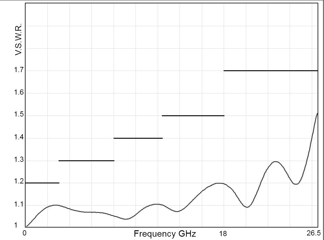
TYPICAL RF PERFORMANCE
INSERTION LOSS & ISOLATION

Frequency (GHz)
TYPICAL OUTLINE DRAWING [1]
SOLDER PIN MODEL
Notes
1. For SP4T, ways 3 and 6 not connected
V.S.W.R
Frequency (GHz)
MICRO-D MODEL
2. All dimensions are in millimeters [inches].
Subminiature Series
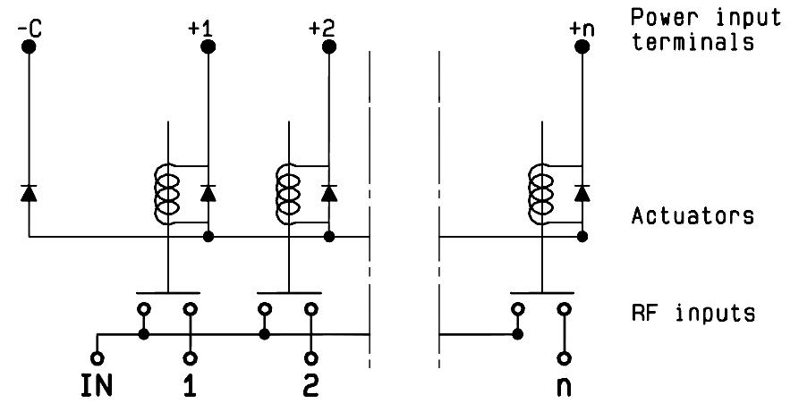
R591 SERIES ELECTRICAL SCHEMATICS
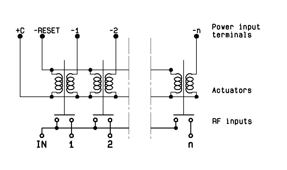
NORMALLY OPEN WITHOUT OPTION
R591-0- -0-

NORMALLY OPEN WITH TTL DRIVE
R591-0- -2-

NORMALLY OPEN WITH POSITIVE COMMON & SUPPRESSION DIODES
R591-0- -4-

NORMALLY OPEN WITH POSITIVE COMMON
R591-0- -1-

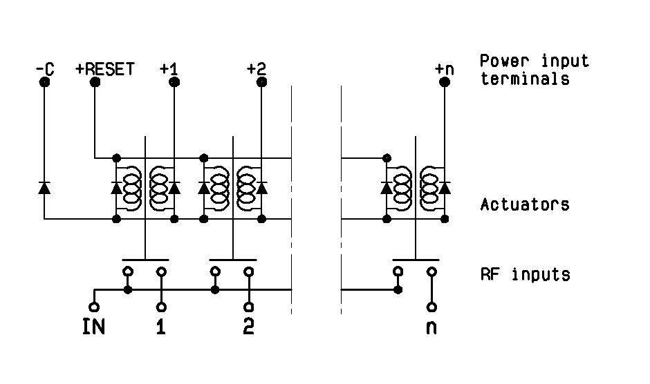
NORMALLY OPEN WITH SUPPRESSION DIODES
R591-0- -3-

LATCHING GLOBAL RESET WITHOUT OPTION
R591-2- -0-

Subminiature Series
LATCHING GLOBAL RESET WITH POSITIVE COMMON
R591-2- -1-
LATCHING GLOBAL RESET WITH POSITIVE COMMON & SUPPRESSION DIODES
R591-2- -4-

LATCHING SEPARATED RESET WITH POSITIVE COMMON
R591-6- -1-

LATCHING GLOBAL RESET WITH SUPPRESSION DIODES
R591-2- -3-
LATCHING SEPARATED RESET WITHOUT OPTION
R591-6- -0-

LATCHING SEPARATED RESET WITH SUPPRESSION DIODES
R591-6- -3-

Subminiature Series
LATCHING SEPARATED RESET WITH POSITIVE COMMON & SUPPRESSION DIODES
R591-6- -4-

PIN IDENTIFICATION
SOLDER PINS (TOP VIEW) [1]
• 16 contact female connector
• NC: not connected
• For SP4T, ways 3 and 6 not connected
• Pin R = reset of all paths
Latching individual reset [2]
Normally open with TTL drive
Notes
1. Compatible with 2.54 mm pitch double row and HE10 connector.
2. Available with "solder pins" models only.
9 PIN MICRO-D (TOP VIEW)
SPNT USB UP TO 40 GHz
SMA – SMA 2.9

PART NUMBER SELECTION
SERIES PREFIX
MODEL
3: Without 50 Ω termination
4: With 50 Ω termination
RF CONNECTORS
F: SMA up to 26 � 5 GHz
8: SMA 2�9 up to 40 GHz [1 & 2]
TYPE
1: Normally open I + C
ACTUATOR VOLTAGE
1: 5 Vdc
NUMBER OF POSITIONS
6: 6 positions
8: 8 positions
OPTIONS
0: Without option
ACTUATOR TERMINALS
1: Mini USB socket
Utilizing Radiall’s proven and patented RAMSES concept, our team of experts and engineers integrated a mini-USB terminal on SP6T and SP8T switches for simplified use especially in test & lab applications.
Featuring an easy-to-integrate design, USB Coaxial Switches are delivered with a 1 meter long USB cable for power supply and switch drive. A soft front panel is provided to control the switches but commonly used software programming platforms such as Visual Basic, C#, C++, LabVIEW and VEE are also compatible
Example of P/N: R573F11601 is a non-terminated SP6T SMA up to 26.5 GHz, Normally Open, 5 Vdc, Indicators with a mini USB port.
Notes
I.C.: Indicator contact
1. Available only with 6 positions.
2. Connector SMA 2.9 is equivalent to "K connector ®", registered trademark of Anritsu.
R57 1 1 1 0
APPLICATION NOTE
USB coaxial switch as cascade
You can use as many USB switches in cascade as you want. Each product is recognized by its automatic affectation to the ComPort and in order to differentiate them, each product has its own serial number which can be read by the software.
In order to provide power supply (5V / 420mA) and drive as many switches as you want with your computer, you will need a hub USB which can provide same power as a classic USB port of the computer (500mA / 5V) or a PCI expansion card USB (if it is a desktop)�
APPLICATION EXAMPLE
AFTER BEFORE

DC power from a power supply and wires to provide power to PF Paths


Control with computer
GRAPHICAL USER INTERFACE WITH MORE THAN ONE PRODUCT
• Every product has its own serial port. To control manually you can also open many soft front panel.
• Each product has its own serial number and different communication port.
• The user has also the possibility to manage the control automatically using LabView drivers provided or using Vb.net, C++ , C# with DLL provided also.
GENERAL SPECIFICATIONS
OPERATING MODE
Average Power
Indicator rating
See Power Rating Chart page 1-13
Indicators status are returned by software
Switching time (max) ms 15 ms
Non-terminated SP6T (R573 series)
Life (min)
Connectors
Actuator terminals
Terminated SP6T (R574 series)
SP8T (all models)
Vibration (MIL STD 202, method 204D, cond D)
Shock (MIL STD 202, method 213B, cond C)
RF PERFORMANCE - SP6T
CONNECTORS FREQUENCY RANGE GH z
RF PERFORMANCE - SP8T
CONNECTORS
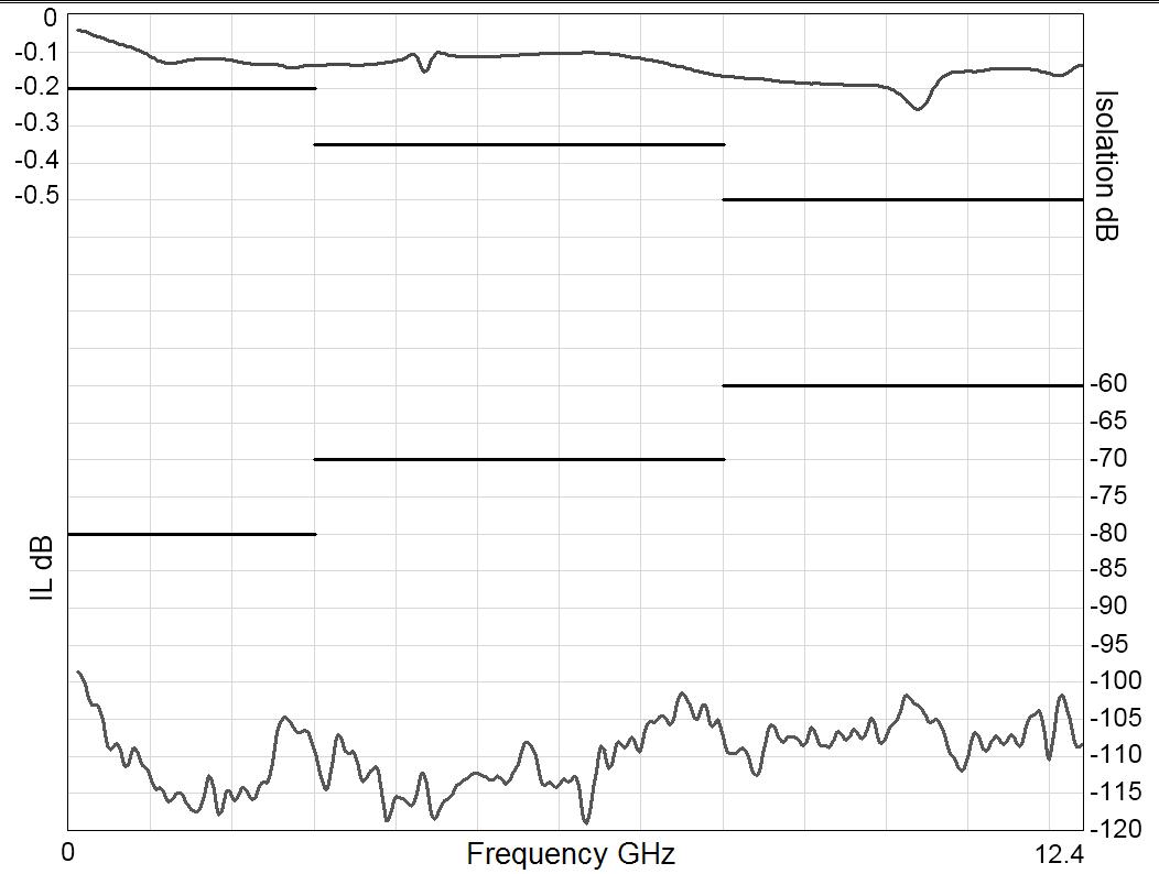
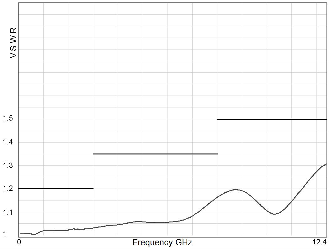
TYPICAL RF PERFORMANCE
Example: SP6T SMA up to 26.5 GHz
INSERTION LOSS & ISOLATION

Frequency (GHz)
Example: SP6T SMA 2.9 up to 40 GHz
INSERTION LOSS & ISOLATION

Frequency (GHz)
Example: SP8T SMA 2.9 up to 26.5 GHz
INSERTION LOSS & ISOLATION

Frequency (GHz)
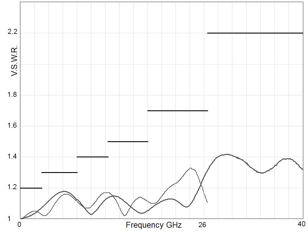
V.S.W.R
Frequency (GHz)
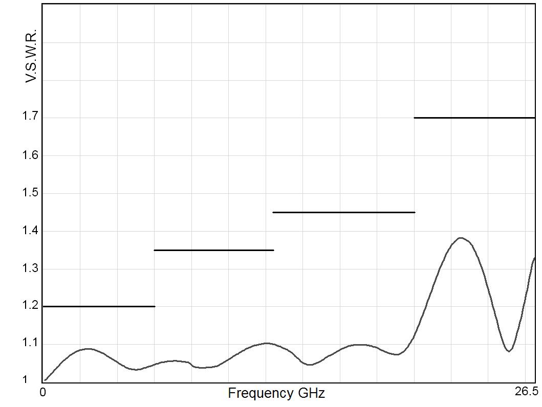
V.S.W.R
Frequency (GHz)
V.S.W.R

Frequency (GHz)
TYPICAL OUTLINE DRAWINGS
Non-terminated or terminated 6 positions
SMA MODEL
Notes
All dimensions are in millimeters [inches].
TYPICAL OUTLINE DRAWINGS
Non-terminated or terminated 8 positions
SMA MODEL
Notes
All dimensions are in millimeters [inches]. For electrical schematics see page 5-43.
SPNT TERMINATED & NON-TERMINATED UP TO 50 GHz SMA – SMA 2.9 - 2.4 MM - QMA - DIN 1.6 / 5.6
Radiall's R573 and R574 multi-throw coaxial switches are offered in many configurations (over 40,000 possible combinations) including terminated and non-terminated options. Radiall offers reliable products, with shorter delivery times and competitive pricing. Excellent typical RF performance make RAMSES switches (40 GHz) ideal for Automated Test Equipment (ATE) and other measurement applications. These switches are suitable for defense, industrial, instrumentation and telecommunication applications �
Example of P/N: R574453605 is a terminated SP6T SMA up to 18 GHz, Latching, Self Cut-Off, 28 Vdc, Indicators and male 25 pin D-Sub connector.
SERIES PREFIX
MODEL
3: Without 50 Ω termination
4: With 50 Ω termination
RF CONNECTORS
3: SMA up to 3 GHz
E: QMA up to 6 GHz [4, 5 & 13]
4: SMA up to 18 GHz [2]
F: SMA up to 26 � 5 GHz [6]
8: SMA 2 9 up to 40 GHz [4 & 14]
J: 2 4 mm up to 50 GHz [11]
9: DIN 1 6/5 6 up to 2 5 GHz [4 & 5]
TYPE
0: Normally open
1: Normally open I � + C �
2: Latching
3: Latching + I.C.
4: Latching + S.C.O. [1 & 4]
5: Latching + S.C.O. + I.C. [1 & 4]
8: Latching + S.C.O. + A.R. [1]
9: Latching + S.C.O. + I.C. + A.R. [1]
Notes
I.C.: Indicator contact / S.C.O. : Self Cut-Off / A.R. : Auto Reset
1. These models are already equipped with suppression diodes
2. 12 positions are available only up to 12.4 GHz, for 12 positions up to 18 GHz select digit F
3. Latching BCD driver enables also a global reset through driver code 0000 (see BCD logic coding page 1-11)
4. Available only up to 6 positions
5. Model "3" only
6. 10 positions are available only up to 22 GHz, 12 positions only up to 18 GHz
7. From 3 to 8 positions, this option is only available for type 0, 1, 2, 3 and for type 8 and 9 combined with 28 Vdc. From 10 to 12 positions, only for type 0, 1, 2 and 3 PART NUMBER SELECTION
ACTUATOR TERMINALS
0: Solder pins
5: D-Sub connector
OPTIONS [15]
0: Without option
1: Positive common [7]
2: Compatible TTL driver [1, 9 & 10]
3: With suppression diodes
4: With suppression diodes and positive common [12]
8: BCD TTL driver compatible [1, 3, 8 & 9]
NUMBER OF POSITIONS
3: 3 positions
4: 4 positions
5: 5 positions
6: 6 positions
8: 8 positions
0: 10 positions
2: 12 positions
ACTUATOR VOLTAGE
2: 12 Vdc
3: 28 Vdc

8. Option available only with type 0, 1, 8 and 9
9. Polarity is not relevant to application for switches with TTL driver
10 From 8 to 12 positions, this option is only available with type 0, 1, 8 and 9.
11. Available only with 4 and 6 positions.
12. Option available only with type 0, 1, 2, and 3.
13. The QLF tradermark (quick lock formula®) standard applies to QMA and QN series and guaranties the full intermateability between suppliers using this tradermark. Using QLF certificied connectors also guarantees the specified level of RF performance
14. Connector SMA 2.9 is equivalent to "K connector ®", registered trademark of Anritsu
15. For precisions see availabilty of options chart page 5-9
RAMSES Series
GENERAL SPECIFICATIONS
Type 2, 3, 4 and 5:
Latching models have a RESET pin which commands the reset of all positions. This command should be used before switching from one position to another. If not, two positions will be set at the same time.
Note: During the RESET operation the global current is: the nominal operating current multiplied by the number of positions.
Type 8, 9:
Latching models with AUTOMATIC RESET are available; these products have an internal SET/RESET circuit which automatically resets all the non-selected positions and sets the desired position. This option simplifies the use of latching switches by suppressing the RESET command in switching sequence.
An electronic circuit supplies successively groups of 2, 3 or 4 actuators, in order to limit the maximum current. The current with this option is the total current of 2, 3 or 4 reset coils in the same time (see table below).
Example: During the AUTOMATIC RESET operation, at 28 Vdc, 4 position switch has a temporary consumption of only 250 mA, during 40 ms maximum.
SWITCHING SEQUENCE
SP10 & 12 T FOR SP6 TO 8T

n = number of positions
OPERATING TOTAL CURRENT AT 23 °C (MA) SPNT LATCHING
NUMBER OF POSITIONS
3 to 4 320 × n 640 125 × n 250
5 to 8 320 × n 960 125 × n 375
10 to 12 320 × n 1280 125 × n 500

Availability of options according to both type and number of positions.
GENERAL SPECIFICATIONS
OPERATING MODE NORMALLY OPEN
Nominal operating voltage (across operating temperature)
Average power
High Level
TTL input
(10 2/13)
(24/30)
(10 2/13)
(24/30)
See table on previous page
See Power Rating Chart page 1-13
2.2 to 5.5 V (TTL Option) / 800 μA max 5.5 volts 3 5 to 5 5 V (BCD Option)
Low Level 0 to 0.8 V (TTL Option) / 20 μA max 0.8 volts 0 to 1 5 V (BCD Option)
Indicator rating 1 W / 30 V / 100 mA
Switching time (Max) ms 15 ms
Life (Min)
Shock (MIL STD 202, method 213B, cond C) 100 g / 6 ms, 1/2 sine operating for SP3 to 6T, survival for SP8 to 12T RAMSES Series
For automatic reset models: SP3T to SP6T = 40 ms SP8T to SP12T = 50 ms
Non-terminated SP3 to 6T (R573 series) SMA - QMA SMA 2 9 - 2 4 mm - 1 6/5 6 5 million cycles 2 million cycles
Terminated SP3 to 6T (R574 series) 2 million cycles SP8 to 12T (all models)
Connectors SMA - SMA 2 9 - 2 4 mm - QMA - DIN 1 6/5 6
Actuator terminals
Solder pins or male 25 pin D-sub connector
Operating temperature range 2 4 mm - DIN 1 6/5 6 -25 ºC to +70 ºC SMA - SMA 2 9 - QMA -40 ºC to +85 ºC
Storage temperature range 2 4 mm - DIN 1 6/5 6 -40 ºC to +85 ºC
SMA - SMA 2 9 - QMA -55 ºC to +85 ºC
Vibration (MIL STD 202, method 204D, cond � D) 10 - 2,000 Hz , 20 g operating for SP3 to 6T, survival for SP8 to 12T
RF PERFORMANCE - SMA CONNECTOR
NUMBER OF POSITIONS
RAMSES Series
RF PERFORMANCE
CONNECTORS
R573 & R574 TYPICAL PERFORMANCE
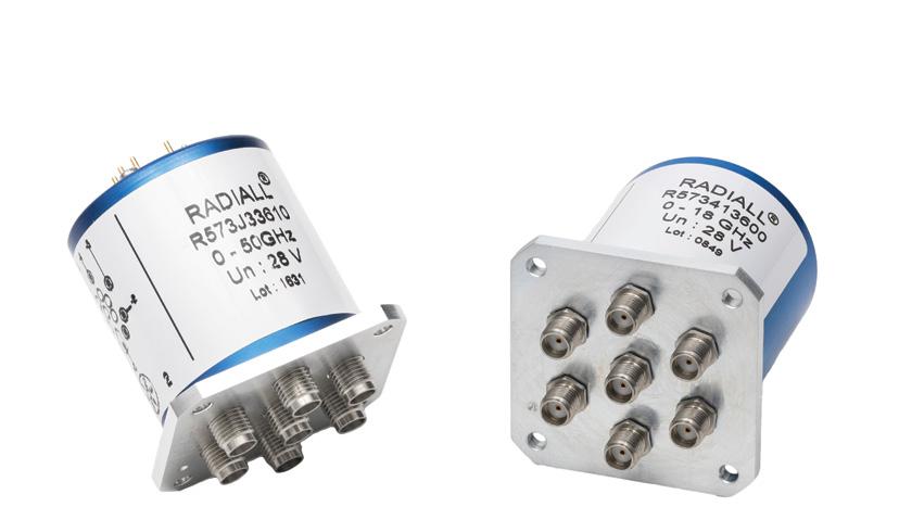
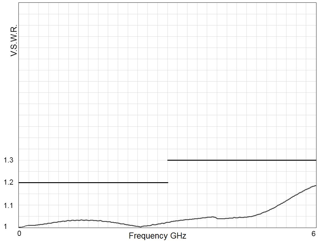
Example: SP6T QMA up to 6 GHz
INSERTION LOSS & ISOLATION

V.S.W.R.
RAMSES Series
Example: Non-terminated SP6T up to 26.5 GHz
INSERTION LOSS & ISOLATION

Frequency (GHz)
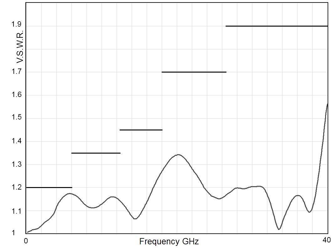
Example: Non-terminated SP6T SMA 2.9 up to 40 GHz
INSERTION LOSS & ISOLATION

Frequency (GHz)
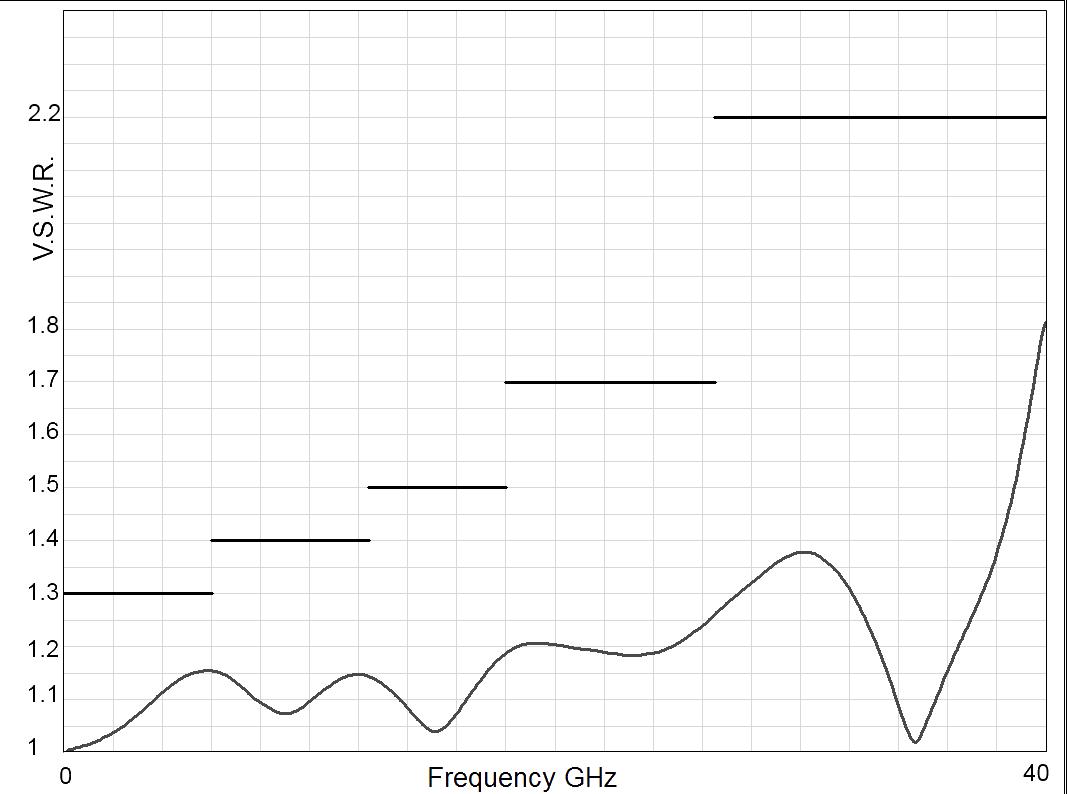
Example: Non-terminated SP6T 2.4 mm up to 50 GHz
INSERTION LOSS & ISOLATION

Frequency (GHz)

Frequency (GHz)
Frequency (GHz)
V.S.W.R

Frequency (GHz)
RAMSES Series
Example: Terminated SP6T up to 26.5 GHz
INSERTION LOSS & ISOLATION

Frequency (GHz)
Example: Terminated SP6T SMA 2.9 up to 40 GHz
INSERTION LOSS & ISOLATION

Frequency (GHz)
Example: Terminated SP6T 2.4 mm up to 50 GHz
INSERTION LOSS & ISOLATION

Frequency (GHz)
Frequency (GHz)

Frequency (GHz)

Frequency (GHz)
RAMSES Series
Example: Non-terminated SP6T 1.6/5.6 up to 2.5 GHz
INSERTION LOSS & ISOLATION

Frequency (GHz)
Example: SP8T SMA up to 26.5 GHz
INSERTION LOSS & ISOLATION

Frequency (GHz)
Example: SP10T SMA up to 22 GHz
INSERTION LOSS & ISOLATION

Frequency (GHz)

Frequency (GHz)
V.S.W.R

Frequency (GHz)
V.S.W.R

Frequency (GHz)
RAMSES Series
Example: SP12T SMA up to 18 GHz
INSERTION LOSS & ISOLATION

Frequency (GHz)
TYPICAL OUTLINE DRAWINGS
NON-TERMINATED 3 TO 6 POSITIONS
CONNECTORS A MAX (MM [INCHES])
SMA up to 26 5 GHz
7 7 [0 303]
SMA 2 9 up to 40 GHz 6 7 [0 264]
2 4 mm up to 50 GHz 6 7 [0 264]
QMA up to 6 GHz 10 8 [0 394]
DIN 1 6 / 5 6 up to 2 5 GHz 11 5 [0 433]
SOLDER PINS
Type 0 or 1 with option 0 - 1 - 3 or 4
Type 2 or 3 with option 0 or 1
Notes All dimensions are in millimeters [inches].
V.S.W.R

Frequency (GHz)
RAMSES Series
TYPICAL OUTLINE DRAWINGS
NON-TERMINATED 3 TO 6 POSITIONS (CONTINUED)
Type 0 or 1 with option 2 or 8
SOLDER PINS
Type 2 or 3 with option 2 - 3 - 4 or 8
Type 4 - 5 - 8 or 9 with option 0 - 1 - 2 or 8
D-SUB CONNECTOR All models
CONNECTORS A MAX (MM [INCHES])
SMA up to 26 5 GHz 7 7 [0 303]
SMA 2 9 up to 40 GHz 6 7 [0 264]
2 4 mm up to 50 GHz 6 7 [0 264]
QMA up to 6 GHz
DIN 1 6 / 5 6 up to 2 5 GHz
8 [0 394]
5 [0 433]
RAMSES Series
TYPICAL OUTLINE DRAWINGS
TERMINATED 3 TO 6 POSITIONS
Type 0 - 1 - 2 or 3 with option 0 - 1 - 3 or 4
Type 0 - 1 - 2 or 3 with option 2 or 8
Type 4 - 5 - 8 or 9 with option 0 - 1 - 2 or 8
Notes All dimensions are in millimeters [inches].
5 [1 811]
5 [2 17]
5 [2 17]
TYPICAL OUTLINE DRAWINGS
Terminated 3 to 6 positions 26.5 GHz, 40 GHz and 50 GHz RAMSES
SMA 26.5 GHz MODEL
SMA 2.9 40 GHz & 2.4 MM 50 GHz MODEL
Type 0 - 1 - 2 or 3 with option 0 - 1 - 3 or 4 48 � 5 [1� 89]
Type 0 - 1 - 2 or 3 with option 2 or 8
Type 4 - 5 - 8 or 9 with option 0 - 1 - 2 or 8
5 [2 � 24]
5 [2 � 24]
Notes
All dimensions are in millimeters [inches].
RAMSES Series
TYPICAL OUTLINE DRAWINGS
Terminated or non-terminated 8 to 12 positions
TERMINATED 8 POSITIONS SMA 26.5 GHz MODEL
TERMINATED 10 POSITIONS SMA 22 GHz MODEL
TYPE
Type 0 - 1 - 2 or 3 with option 0 - 1 - 3 or 4
Type 0 - 1 - 2 or 3 with option 2 or 8 and Type 4 - 5 - 8 or 9 with option 0 - 1 - 2 or 8
Notes
All dimensions are in millimeters [inches].
B MAX (MM [INCHES]) SOLDER PINS
50 [1 97]
61 [2 40]
TERMINATED 12 POSITIONS SMA 18 GHz MODEL
SPNT UP TO 12.4 GHz - RAMSES CONCEPT
N - BNC - TNC

Radiall's R573 and R574 multi-throw coaxial switches are offered in many configurations (over 40,000 possible combinations), including terminated and non-terminated options. Radiall offers reliable products, with shorter delivery times and competitive pricing. Excellent typical RF performance make RAMSES switches (12.4 GHz) ideal for Automated Test Equipment (ATE) and other measurement applications. These switches are suitable for defense, industrial, and telecommunication applications �
Example of P/N: R573103600 is a SP6T N up to 12.4 GHz, Normally Open, 28 Vdc, and solder pins.
NUMBER SELECTION
SERIES PREFIX
MODEL
3: Without 50 Ω termination
4: With 50 Ω termination
RF CONNECTORS
0: N up to 3 GHz [10]
1: N up to 12 4 GHz [8 & 10]
2: BNC up to 3 GHz [3 & 4]
5: TNC up to 3 GHz [3 & 4]
6: TNC up to 12 4 GHz [3 & 4]
TYPE
0: Normally open
1: Normally open I + C
2: Latching
3: Latching + I.C.
4: Latching + S.C.O. [1 & 3]
5: Latching + S.C.O. + I.C. [1 & 3]
8: Latching + S.C.O. + A.R. [1]
9: Latching + S.C.O. + I.C. + A.R. [1]
Notes
I.C.: Indicator contact / S.C.O. : Self Cut-Off / A.R. : Auto Reset
Standard products are equipped with negative common
1. These models are already equipped with suppression diodes
2. Latching BCD driver enables also a global reset through driver code 0000 (see BCD logic coding page 1-13)
3. Available only up to 6 positions
4. Model "3" only
5. Available only for type 0, 1, 2 and 3
ACTUATOR TERMINALS
0: Solder pins
5: D-Sub connector
OPTIONS [11]
0: Without option
1: Positive common [5]
2: Compatible TTL driver [1, 7 & 9]
3: With suppression diodes
4: With suppression diodes and positive common [5]
8: BCD TTL driver compatible [1, 2, 6 & 7]
NUMBER OF POSITIONS
3: 3 positions
4: 4 positions
5: 5 positions
6: 6 positions
8: 8 positions
0: 10 positions
2: 12 positions
ACTUATOR VOLTAGE
2: 12 Vdc
3: 28 Vdc
6. Available only with type 0, 1, 8 and 9
7. Polarity is not relevant to application for switches with TTL driver
8. 8 to 12 positions are available only up to 8 GHz
9. From 8 to 12 positions, this option is only available with type 0, 1, 8 and 9
10. From 8 to 12 positions, this connector is only available without 50 Ω termination
11. For precisions see availabilty of options chart page 5-27
GENERAL SPECIFICATIONS
Type 2, 3, 4 and 5:
Latching models have a RESET pin which commands the reset of all positions. This command should be used before switching from one position to another. If not, two positions will be set at the same time.
Note: During the RESET operation, the global current and the nominal operating current are multiplied by the number of positions.
Type 8, 9:
Latching models with AUTOMATIC RESET are available; these products have an internal SET/RESET circuit which automatically resets all the non-selected positions and sets the desired position. This option simplifies the use of latching switches by suppressing the RESET command in switching sequence.
An electronic circuit supplies successively groups of 2, 3 or 4 actuators, in order to limit the maximum current. The current with this option is the total current of 2, 3 or 4 reset coils in the same time (see table below).
Example: During the AUTOMATIC RESET operation, at 28 Vdc, 4 position switch has a temporary consumption of only 250 mA, during 40 ms maximum.
SWITCHING SEQUENCE
FOR SP10 TO 12T FOR SP6 TO 8T

n = number of positions
OPERATING TOTAL CURRENT AT 23 °C (MA) SPNT LATCHING
NUMBER OF POSITIONS 12 VOLTS 28 VOLTS
3 to 4 320 × n
5 to 8

Availability of options according to both type and number of positions.
GENERAL SPECIFICATIONS
See table on previous page
See Power Rating Chart page 1-13
Indicator
Switching time (max) ms 15 ms For automatic reset models: SP3T to SP6T = 40 ms SP8T to SP12T = 50 ms
Life (min)
Non-terminated SP3 to 6T (R573 series) 2 million cycles
Terminated SP3 to 6T (R574 series)
SP8 to 12T (all models)
Connectors N - TNC - BNC
Actuator terminals
Solder pins or male 25 pin D-Sub connector
Operating temperature range -40 ºC to +85 ºC
Storage temperature range -55 ºC to +85 ºC
Vibration (MIL STD 202, method 204D, cond C) 10 - 2,000 Hz, 10 g operating
Shock (MIL STD 202, method 213B, cond �C) 50 g/1 ms, 1/2 sine operating
RF PERFORMANCE
N - TNC - BNC Connector
POSITIONS
Notes
See page 5-29 for typical RF performance.
RAMSES Series
R573 & R574 TYPICAL PERFORMANCE
Example: SP6T N up to 12.4 GHz
INSERTION LOSS & ISOLATION
Frequency (GHz)
Example: SP6T TNC up to 12.4 GHz
INSERTION LOSS & ISOLATION

Frequency (GHz)
Example: SP8T up to 8 GHz
INSERTION LOSS & ISOLATION

Frequency (GHz)
V.S.W.R

Frequency (GHz)
V.S.W.R
Frequency (GHz)
V.S.W.R

Frequency (GHz)
RAMSES Series
TYPICAL OUTLINE DRAWINGS
Terminated or non-terminated 3 to 12 positions
8 POSITIONS 8 GHz WITH SOLDER PINS MODEL
Notes All dimensions are in millimeters [inches].
[INCHES])
5 [0 748]
5 [0 472]
� 5 [0� 472]
10 POSITIONS 8 GHz WITH D-SUB CONNECTOR MODEL
RF CONNECTOR ALLOCATION FOR SPNT SERIES
ALL CONNECTORS
Connectors A: 1.6/5.6, QMA, SMA, SMA 2.9, 2.4 mm
Other Connectors: N, BNC, TNC
SPNT 3 WAYS
NON-TERMINATED VERSION
Up to 40 GHz models Without option Connectors A (except 2 � 4 mm)
SPNT 4 WAYS
Up to 40 GHz models With option Connectors A and other connectors (except 2 � 4 mm)
TERMINATED VERSION
Up to 18 GHz models Connectors A and other connectors (except 2 � 4 mm)
GHz and 40 GHz models with SMA - SMA 2 �9

NON-TERMINATED VERSION TERMINATED VERSION
Up to 50 GHz models Without option Connectors A
Up to 50 GHz models With option Connectors A and other connectors
Up to 18 GHz models Connectors A and other connectors (except 2 4 mm)
5
40
and 50
models with SMA - SMA 2.92 4 mm

SPNT 5 WAYS
NON-TERMINATED VERSION
Up to 40 GHz models Without option Connectors A (except 2 4 mm)
Up to 40 GHz models With option Connectors A and other connectors (except 2 4 mm)
TERMINATED VERSION
Up to 18 GHz models Connectors A and other connectors (except 2 4 mm) 26.5 GHz and 40 GHz models with SMA - SMA 2 9

Connectors A: 1.6/5.6, QMA, SMA, SMA 2.9, 2.4 mm
Other Connectors: N, BNC, TNC
SPNT 6 WAYS
NON-TERMINATED VERSION
Up to 50 GHz models Without Option Connectors A Up to 50 GHz models With Option Connectors A and other connectors
TERMINATED VERSION
to 22 GHz models Connectors A and other connectors
and

SPNT 8 WAYS
SMA and N connectors
SPNT 10 WAYS
SMA and N connectors
SPNT 12 WAYS
SMA and N connectors
Accessories SPnT & Electrical Schematics
COAXIAL SPNT - ACCESSORIES
PRINTED CIRCUIT BOARD INTERFACE CONNECTOR
A printed circuit board interface connector (ordered separately) has been designed for easy mounting on terminals
For SPnT model R573 and R574 series: Radiall part number: R599 906 000 for 3 to 6 positions, R599 908 000 for 8 positions, R599 900 000 for 10 positions, and R599 902 000 for 12 positions.
R599906000
R599902000
R599908000
R599900000

Accessories SPnT & Electrical Schematics
Mounting Bracket
Two different metal brackets have been designed for an easy mechanical mounting of our SPnT switches with a circular flange for customer installation. These brackets must be ordered separately and assembled according to our recommended process on the Technical Data Sheets
MODEL WITH SCREWS (R599320000)


Notes
All dimensions are in millimeters [inches]. For assembling process please see Technical Data Sheet.
Accessories SPnT & Electrical Schematics
MODEL WITH ADHESIVE (R59992X000)

Protective adhesive tape surface
GENERAL TOLERANCES: ±0.5 MM [0.02]
Notes
All dimensions are in millimeters [inches]. This model can also be mounted on our SPnT switches with a square flange. For adhesive bonding process please see Technical Data Sheet.
Accessories SPnT & Electrical Schematics
FOR MODELS WITH CONNECTORS SMA, QMA, SMA 2.9, 2.4 MM, DIN 1.6/5.6
NUMBER OF POSITIONS
3 to 6 positions
8 positions
10 positions
12 positions
FOR MODELS WITH CONNECTORS N, TNC, BNC
NUMBER OF POSITIONS
3 to 6 positions
8 to 12 positions
MOUNTING SQUARE FLANGE
MODEL PART NUMBER
R573 series
R574 series
R573 series
R574 series
R573 series
R574 series
R573 series
R574 series
MODEL
R573 series
R574 series
R573 series
R574 series
R599320000
R599920000
R599920000
R599921000
R599922000
PART NUMBER
R599921000
Not Available
A square flange has been designed for easy mechanical mounting of our SPnT switches with a circular flange for customer installation. These flanges must be ordered separately (similar to the mounting bracket) and assembled according to our recommended process on the following page.

TYPICAL OUTLINE DRAWING
Accessories SPnT & Electrical Schematics
MATERIAL: ALUMINIUM WITH CR3 PASSIVATION
PART
FOR MODELS WITH CONNECTORS SMA, QMA, SMA 2.9, 2.4 MM, DIN 1.6/5.6
R573 series
3 to 6 positions
R574 series R599311000 R599309000 8 positions
positions
positions
FOR MODELS WITH CONNECTORS N, TNC, BNC
NUMBER OF POSITIONS
3 to 6 positions
D-SUB CONNECTOR LOCATION
R573 & R574
3 to 6 positions

Notes
R573 series
R574 series
R573 series
R574 series
R573 series
R574 series
R573 series R599315000
R574 series
R573 & R574 10 positions

All dimensions are in millimeters [inches]. For assembling process please see Technical Data Sheet.
R573 & R574 8 & 12 positions

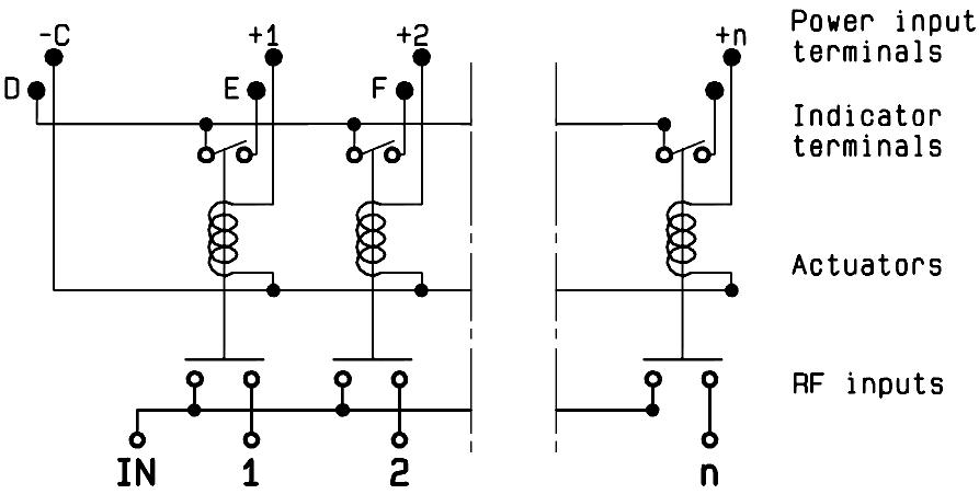
COAXIAL SPNT - ELECTRICAL SCHEMATICS
R573 - R574 SERIES
NORMALLY OPEN Accessories SPnT & Electrical Schematics
WITHOUT OPTION
R573-0--0- / R574-0--0-

WITH SUPPRESSION DIODES
R573-0--3- / R574 -0- -3-
WITH TTL DRIVER (SUPRESSION DIODES ARE INCLUDED)
R573-0--2- / R574 -0- -2-

WITH INDICATOR CONTACT
R573-1--0- / R574 -1- -0-
WITH SUPPRESSION DIODES & INDICATOR CONTACT
R573-1--3- / R574 -1- -3-

WITH TTL DRIVER & INDICATOR CONTACT (SUPRESSION DIODES ARE INCLUDED)
R573-1--2- / R574 -1- -2-

COAXIAL SPNT - ELECTRICAL SCHEMATICS (CONTINUED)
R573 - R574 SERIES
NORMALLY OPEN Accessories SPnT & Electrical Schematics
WITH BCD DRIVER, TTL COMPATIBLE (SUPPRESSION DIODES ARE INCLUDED)
R573-0--8- / R574-0--8-

WITH POSITIVE COMMON
R573-0--1- / R574 -0- -1-

WITH POSITIVE COMMON AND SUPPRESSION DIODES
R573-0--4- / R574 -0- -4-

WITH BCD DRIVER, TTL COMPATIBLE & INDICATOR CONTACT (SUPPRESSION DIODES ARE INCLUDED)
R573-1--8- / R574 -1- -8-

WITH POSITIVE COMMON AND INDICATOR CONTACT
R573-1--1- / R574 -1- -1-

WITH POSITIVE COMMON, SUPPRESSION DIODES & INDICATOR CONTACT
R573-1--4- / R574 -1- -4-

Accessories SPnT & Electrical Schematics
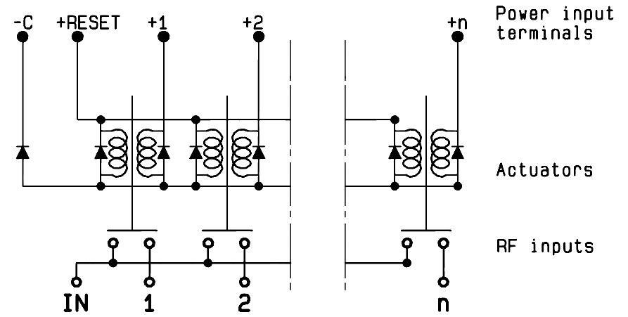
COAXIAL SPNT - ELECTRICAL SCHEMATICS
R573 - R574 SERIES
LATCHING
WITHOUT OPTION
R573-2--0- / R574-2--0-

WITH SUPPRESSION DIODES
R573-2--3- / R574 -2- -3-
WITH TTL DRIVER (SUPRESSION DIODES ARE INCLUDED)
R573-2--2- / R574 -2- -2-

WITH INDICATOR CONTACT
R573-3--0- / R574 -3- -0-

WITH SUPPRESSION DIODES AND INDICATOR CONTACT
R573-3--3- / R574 -3- -3-

WITH TTL DRIVER & INDICATOR CONTACT (SUPRESSION DIODES ARE INCLUDED)
R573-3--2- / R574 -3- -2-

Accessories SPnT & Electrical Schematics
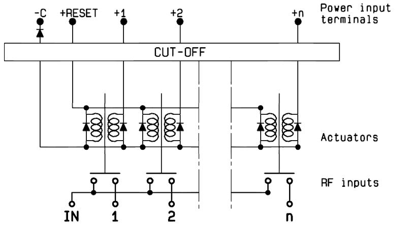
COAXIAL SPNT - ELECTRICAL SCHEMATICS (CONTINUED)
R573 - R574 SERIES
LATCHING
WITH CUT-OFF (SUPPRESSION DIODES ARE INCLUDED)
R573-4--0- / R574-4--0-
WITH CUT-OFF & AUTO REST (SUPPRESSION DIODES ARE INCLUDED)
R573 -8- -0- / R574 -8- -0-

WITH TTL DRIVER AND CUT-OFF (SUPPRESSION DIODES ARE INCLUDED)
R573-4--2- / R574 -4- -2-

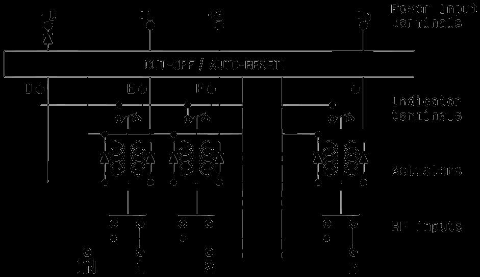
WITH CUT-OFF AND INDICATOR CONTACT (SUPPRESSION DIODES ARE INCLUDED)
R573-5--0- / R574 -5- -0-

WITH CUT-OFF, AUTO REST & INDICATOR CONTACT (SUPPRESSION DIODES ARE INCLUDED)
R573-9--0- / R574 -9- -0-
WITH TTL DRIVER, CUT-OFF & INDICATOR CONTACT (SUPPRESSION DIODES ARE INCLUDED)
R573-5--2- / R574 -5- -2-

Accessories SPnT & Electrical Schematics
COAXIAL SPNT - ELECTRICAL SCHEMATICS (CONTINUED)
R573 - R574 SERIES
LATCHING
WITH TTL DRIVER, CUT-OFF & AUTO RESET (SUPPRESSION DIODES ARE INCLUDED)
R573-8--2- / R574-8--2-

WITH CUT-OFF, FORCE OR AUTO RESET, BCD DRIVER, TTL COMPATIBLE (SUPPRESSION DIODES ARE INCLUDED)
R573-8--8- / R574 -8- -8-
WITH POSITIVE COMMON
R573-2--1- / R574 -2- -1-

WITH TTL DRIVER, CUT-OFF, AUTO RESET & INDICATOR CONTACT (SUPPRESSION DIODES ARE INCLUDED)
R573-9--2- / R574 -9- -2-

WITH CUT-OFF, FORCE OR AUTO RESET, BCD DRIVER, TTL COMPATIBLE & INDICATOR CONTACT (SUPPRESSION DIODES ARE INCLUDED)
R573-9--8- / R574 -9- -8-

WITH POSITIVE COMMON & INDICATOR CONTACT (SUPRESSION DIODES ARE INCLUDED)
R573-3--1- / R574 -3- -1-
Accessories SPnT & Electrical Schematics
COAXIAL SPNT - ELECTRICAL SCHEMATICS (CONTINUED)
R573 - R574 SERIES
LATCHING
WITH POSITIVE COMMON & SUPPRESSION DIODES (SUPPRESSION DIODES ARE INCLUDED)
R573-2--4- / R574-2--4-

WITH POSITIVE COMMON, CUT-OFF, AUTO RESET
R573-8--1- / R574-8--1-

USB SERIES
NORMALLY OPEN WITH INDICATOR CONTACT
R573-11-01 / R574-11-01

WITH POSITIVE COMMON, SUPPRESSION DIODES & INDICATOR CONTACT
R573-3--4- / R574 -3- -4-

WITH POSITIVE COMMON, CUT-OFF, AUTO RESET & INDICATOR CONTACT
R573-9--1- / R574-9--1-

HIGH PERFORMANCE MULTIPORT SWITCHES
SPNT UP TO 40 GHz
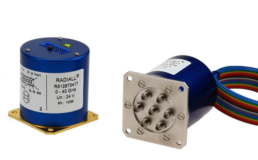
Radiall’s TITANIUM switches are optimized to perform at a high level over an extended life cycle. With outstanding RF performance, and a guaranteed insertion loss repeatability of 0.03 dB over a life span of 2.5 million switching cycles, Radiall's TITANIUM switches are a perfect solution for automated test and measurement equipment, as well as signal monitoring devices.
Example of P/N: R514F73617 is a SP6T SMA up to 26.5 GHz, Latching, Indicators, Self cut-off, Auto-Reset, 24 Vdc and HE10 receptacle.
PART NUMBER SELECTION
SERIES PREFIX
MODEL
3: Without 50 Ω termination
4: With 50 Ω termination
RF CONNECTORS
3: SMA up to 6 GHz
4: SMA up to 20 GHz
F: SMA up to 26 � 5 GHz
8: SMA 2�9 up to 40 GHz [1]
TYPE
7: Latching + Self cut-off + Auto Reset + Indicators
ACTUATOR VOLTAGE
3: 24 Vdc
NUMBER OF POSITIONS
4: 4 positions
6: 6 positions
OPTIONS *
1: Positive common (without TTL)
2: TTL/5 V logic with 24 Vdc supply [2]
ACTUATOR TERMINAL
7: HE 10 receptacle, delivered with 750 mm (30 inches) ribbon cable + HE10 connector
DOCUMENTATION
-: Certificate of conformity
C: Calibration certificate
R: Calibration certificate + RF curves
Notes
1. Connector SMA 2.9 is equivalent to "K connector ®", registered trademark of Anritsu.
2. Polarity is not relevant to application for switches with TTL driver
GENERAL SPECIFICATIONS
OPERATING MODE LATCHING
Nominal operating voltage (across operating temperature) Vdc 24 (20/32) Coil resistance (+/-10%) Ω 120
Operating current at 23 °C mA 200
Maximum stand-by current mA 50
Average power Terminated Model All models
RF path Cold switching: See Power page 5-50 Hot switching: 1 Watt Cw
Internal terminations 1 Watt average into 50 Ω TTL input
withstanding
Indicator specifications
Minimum "OFF" resistance
Switching time (max) ms 15 Life (min) SMA 2 � 5 million cycles SMA 2 9 1 million cycles
Connectors SMA - SMA 2 9
Actuator terminals HE10 ribbon receptacle
Weight (max) g 230
ENVIRONMENTAL SPECIFICATIONS
Operating temperature range -25 ºC to +75 ºC
Storage temperature range -55 ºC to +85 ºC
Temperature cycling (MIL-STD-202, Method 107D, Cond.A) -55 ºC to +85 ºC (10 cycles)
Vibration (MIL STD 202, Method 204D, Cond D) 10 - 2,000 Hz, 10 g - operating
Shock (MIL STD 202, Method 213B, Cond C) 50 g/6 ms, 1/2 sine - operating
Moisture resistance (MIL STD 202, Method 106E, Cond � E) 65 ºC, 95% RH, 10 days
Altitude storage (MIL STD 202, Method 105C, Cond.B) 50,000 ft (15,240 meters)
RFI (MIL STD 1344, Method 3008 or IEC 61726) 55 dB at 20 GHz Magnetic field < 5.10-5 gauss at 1 meter
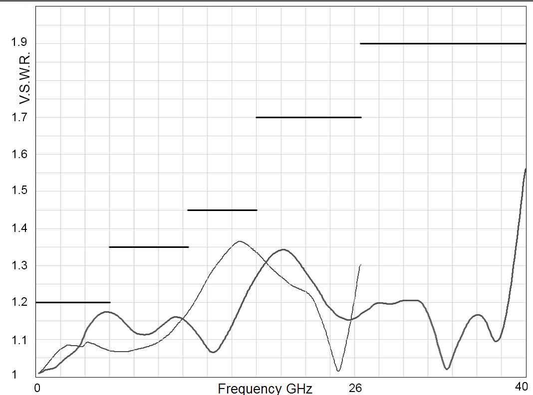
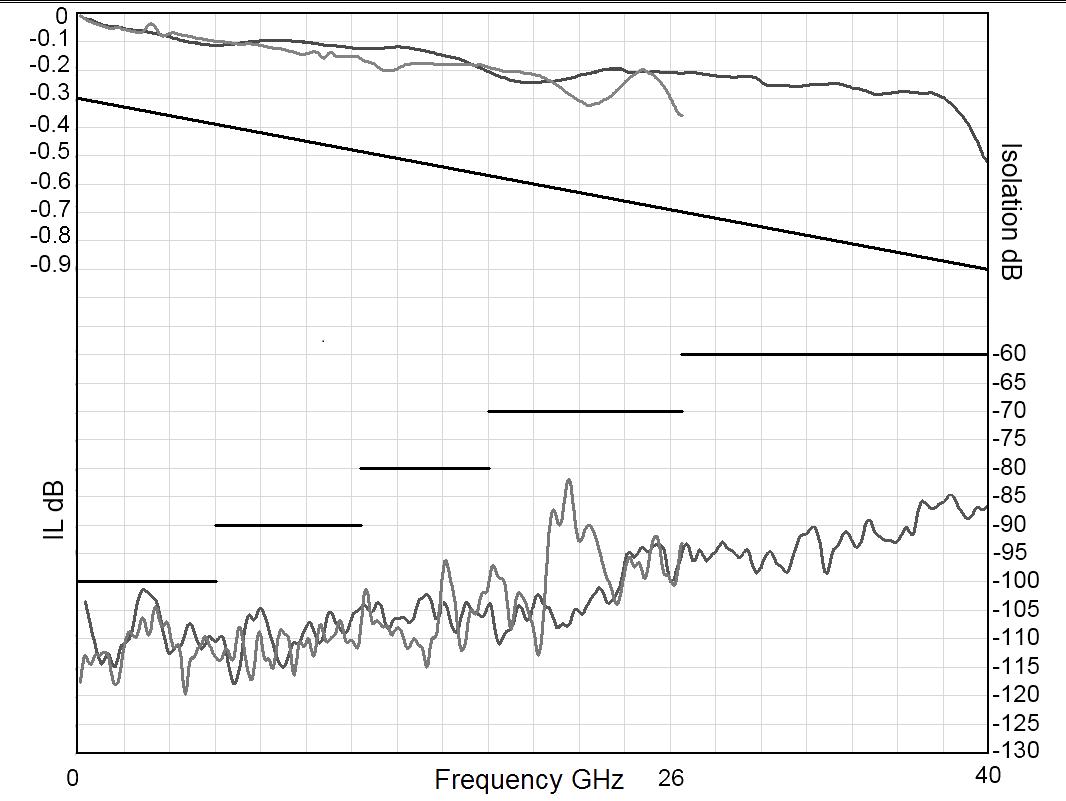
RF PERFORMANCE
TYPICAL
INSERTION LOSS & ISOLATION

ELECTRONIC POSITION INDICATORS
The electronic position indicators use photo-MOS transistors, which are driven by the mechanical position of the RF paths moving elements. The circuitry consists of a common which can be connected to an output corresponding to a selected RF path. If one or several RF paths are closed, the corresponding indicators are connected to the common. The photo-MOS transistors are configured for AC and/or DC operation. The electronic position indicators require the supply (20 to 32 VDC) to be connected to pin 1 and ground connected to pin 15.

Notes Ways 1 and 4 are not connected for SP4T switches.
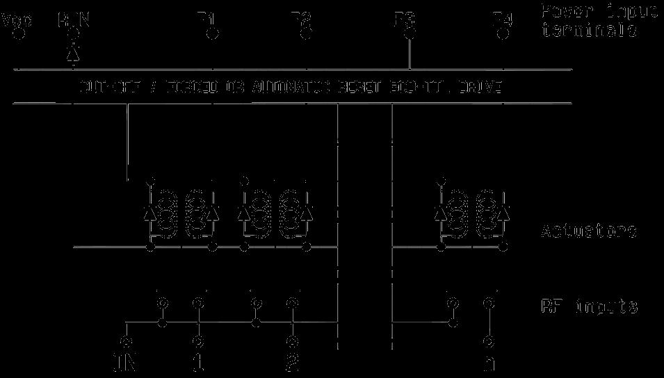
TYPE 7: WITH TTL (OPTION “2”) / WITHOUT TTL (OPTION “1”) & INDICATORS
Each RF path can be closed by applying ground or TTL "High" for option 2 to the corresponding "drive" pin. In general, except for Make-Before-Break drive, all other RF paths are simultaneously opened by internal logic.

Standard drive option “1”:
• Connect pin 15 to ground
• Connect pin 1 to supply (+20 VDC to +32 VDC)
• Select (close) desired RF path by applying ground to the corresponding "drive" pin (Ex: apply ground to pin 3 to close RF path 1)
• To select another path, ensure that all unwanted RF path "drive" pins are disconnected from ground (to prevent multiple RF path engagement), then apply ground to the "drive" pin which corresponds to the desired RF path
• To open all RF paths, ensure that all RF path "drive" pins are disconnected from ground. Complete the operation by applying ground to pin 16
TTL drive option “2”:
• Connect pin 15 to ground
• Connect pin 1 to supply (+20 VDC to +32 VDC)
• Select (close) desired RF path by applying TTL "High" to the corresponding "drive" pin (Ex: apply TTL "High" to pin 3 to close RF path 1)
• To select another path, ensure that all unwanted RF path "drive" pins are in TTL "low" position (to prevent multiple RF path engagement), then apply TTL "high" to the "drive" pin which corresponds to the desired RF path
• To open all RF paths, ensure that all RF path "drive" pins are in TTL "Low" position. Complete the operation by applying TTL "High" to pin 16
Break-Before-Make:
Open the undesired RF path for at least 15 minutes (minimum), then close the new RF port
Make-Before-Break:
Ensure that the previously selected RF path “drive” is connected to ground (or TTL “High” for option “2”), then close the new RF path
Notes Ways 1 and 4 are not connected for SP4T switches.
TYPICAL OUTLINE DRAWING
SMA CONNECTORS
Notes
All dimensions are in millimeters [inches]. Ways 1 and 4 are not connected for SP4T switches.
POWER RATING CHART
This graph is based on the following conditions:
• Ambient temperature: + 25 °C
• Sea level
• V.S.W.R.: 1 and cold switching

DERATING FACTOR VERSUS VSWR
The average power input must be reduced for load V.S.W.R. above 1:1.

Notes Ways 1 and 4 are not connected for SP4T switches.
HIGH PERFORMANCE MULTIPORT SWITCHES
SPNT TERMINATED UP TO 40 GHz

Radiall’s PLATINUM series switches are optimized to perform at a high level over an extended life cycle. With outstanding RF performance, and a guaranteed insertion loss repeatability of 0.03 dB over a life span of 10 million switching cycles, Radiall's PLATINUM series switches are a perfect solution for automated test and measurement equipment, as well as signal monitoring devices.
Example of P/N: R594873427 is a SPnT SMA 2.9 up to 40 GHz, Latching with Indicators, Self cut-off, Auto-Reset, TTL driver and HE10 connector.
PART NUMBER SELECTION
SERIES PREFIX
RF CONNECTORS
3: SMA up to 6 GHz
4: SMA up to 20 GHz
F: SMA up to 26 � 5 GHz
8: SMA 2�9 up to 40 GHz [1]
TYPE
4: Latching + Self cut-off without indicator
7: Latching + Self cut-off + Auto Reset + Indicators
ACTUATOR VOLTAGE
3: 24 Vdc
NUMBER OF POSITIONS
4: 4 positions
6: 6 positions
OPTIONS
1: Positive common (without TTL)
2: TTL/5 V logic with 24 Vdc supply [2 & 3]
ACTUATOR TERMINAL
7: HE 10 receptacle, delivered with 750 mm (30 inches) ribbon cable + HE10 connector
DOCUMENTATION
-: Certificate of conformity
C: Calibration certificate
R: Calibration certificate + RF curves
Notes
Ways 1 and 4 are not connected for SP4T switches.
1. Connector SMA 2.9 is equivalent to "K connector ®", registered trademark of Anritsu
2. Polarity is not relevant to application for switches with TTL driver
3. Only available with type "7"
GENERAL SPECIFICATIONS
OPERATING MODE LATCHING
Nominal operating voltage (across operating temperature) Vdc 24 (20/32) Coil resistance (+/-10%) Ω 120
Operating current at 23 °C mA 200
Maximum stand-by current mA 50
Average power
TTL input
Indicator specifications
RF path Cold switching: See Power page 5-59 Hot switching: 1 Watt Cw
Internal terminations 1 Watt average into 50 Ω
Maximum withstanding voltage 60 V
Maximum current capacity 150 mA
Maximum "ON" resistance 2.5 Ω
Minimum "OFF" resistance 100 MΩ
Switching time (max) ms 15
Life (min) SMA 10 million cycles SMA 2 9 2 5 million cycles
Connectors SMA - SMA 2 �9
Actuator terminals HE10 ribbon receptacle
Weight (max) g 230
ENVIRONMENTAL SPECIFICATIONS
Operating temperature range -25 ºC to +75 ºC
Storage temperature range -55 ºC to +85 ºC
Temperature cycling (MIL-STD-202, Method 107D, Cond.A) -55 ºC to +85 ºC (10 cycles)
Vibration (MIL STD 202, Method 204D, Cond D) 10 - 2,000 Hz, 10 g - operating Shock (MIL STD 202, Method 213B, Cond C) 50 g/6 ms, 1/2 sine - operating
Moisture resistance (MIL STD 202, Method 106E, Cond E) 65 ºC, 95% RH, 10 days
Altitude storage (MIL STD 202, Method 105C, Cond.B) 50,000 ft (15,240 meters)
RFI (MIL STD 1344, Method 3008 or IEC 61726) 55 dB at 20 GHz Magnetic field < 5.10-5 gauss at 1 meter
RF PERFORMANCE
TYPICAL RF PERFORMANCE
V.S.W.R INSERTION LOSS & ISOLATION

ELECTRONIC POSITION INDICATORS
(This option is not available with type 4)
The electronic position indicators use photo-MOS transistors, which are driven by the mechanical position of the RF paths moving elements. The circuitry consists of a common which can be connected to an output corresponding to selected RF path. If one or several RF paths are closed, the corresponding indicators are connected to the common. The photo-MOS transistors are configured for AC and/or DC operation. The electronic position indicators require the supply (20 to 32 VDC) to be connected to pin 1 and ground connected to pin 15.
Notes Ways 1 and 4 are not connected for SP4T switches.
DRIVING THE SWITCH
Each RF path is driven independently, and can be closed or open by applying ground to the corresponding "open” or “close" pin�

Standard drive:
• Connect pin 15 to ground
• Connect pin 1 to supply (+20 VDC to +32 VDC)
• Select desired RF path by applying ground to the corresponding "close" pin (Ex: ground pin 3 to close RF path 1)
• To open desired RF path connect ground to the corresponding "open" pin (Ex: ground pin 4 to open RF path 1)
• To open all RF paths, first ensure that all RF path "close" pins are disconnected from ground, then to complete the operation, connect pin 16 to ground
Make-Before-Break:
Make-Before-Break switching can be accomplished by closing the new RF path before opening the previously selected RF path. To complete the operation, close the new RF port for at least 15 minutes (minimum), then open the previously selected RF port
TYPE 7: WITH TTL (OPTION “2”) / WITHOUT TTL (OPTION “1”) & INDICATORS
Each RF path can be closed by applying Ground or TTL "High" for option 2 to the corresponding "drive" pin. In general, except for Make-Before-Break drive, all other RF paths are simultaneously opened by internal logic.

Standard drive option “1”:
• Connect pin 15 to ground
• Connect pin 1 to supply (+20 VDC to +32 VDC)
• Select (close) desired RF path by applying ground to the corresponding "drive" pin (Ex: apply ground to pin 3 to close RF path 1)
• To select another path, ensure that all unwanted RF path "drive" pins are disconnected from ground (to prevent multiple RF path engagement), then apply ground to the "drive" pin which corresponds to the desired RF path
• To open all RF paths, ensure that all RF path "drive" pins are disconnected from ground, then complete the operation by applying ground to pin 16
TTL drive option “2”:
• Connect pin 15 to ground
• Connect pin 1 to supply (+20 VDC to +32 VDC)
• Select (close) desired RF path by applying TTL "High" to the corresponding "drive" pin (Ex: apply TTL "High" to pin 3 to close RF path 1)
• To select another path, ensure that all unwanted RF path "drive" pins are in TTL "Low" position (to prevent multiple RF path engagement), then apply TTL "High" to the "drive" pin which corresponds to the desired RF path
• To open all RF paths, ensure that all RF path "drive" pins are in TTL "Low" position, then complete the operation by applying TTL "High" to pin 16
Break-Before-Make:
Open the undesired RF path after 15 minutes (minimum), then close the new RF port.
Make-Before-Break:
Ensure that the previously selected RF path “drive” is connected to ground (or TTL “High” for option “2”), then close the new RF path.
Notes Ways 1 and 4 are not connected for SP4T switches.
TYPICAL OUTLINE DRAWING
SMA CONNECTORS
Notes
All dimensions are in millimeters [inches]. Ways 1 and 4 are not connected for SP4T switches. Platinum Series
SMA 2.9 CONNECTORS
POWER RATING CHART
This graph is based on the following conditions:
• Ambient temperature: + 25 °C
• Sea level
• V.S.W.R.: 1 and cold switching
DERATING FACTOR VERSUS VSWR
The average power input must be reduced for load V.S.W.R. above 1:1.
Optional Features
OPTIONAL FEATURES EXAMPLES OF DEDICATED APPLICATION OPTIONS

SPnT with flat ribbon cable for easy installation with limited space

SPnT models can be fitted with external loads (up to 50 GHz) for an easy maintenance of equipment.

SP3T used for a military application with sequential access and severe environmental characteristics
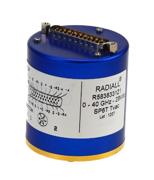
Thermal vacuum SPnT up to 50 GHz designed based on our expertise in Space For more detailed information, see page 7-18 to 7-20.
7P6T switch for a Custom Matrix Switch ( 4P3T ) with 4 Input ports and 4 Output ports configured for 3 transmission systems and one redundancy channel (N+1: N type) for example
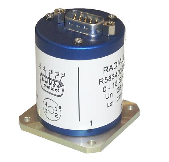
Unterminated SP3-6T with 9 pins D-sub connector instead of solder pins