
SIMPLIFICATION IS OUR INNOVATION Visit www.radiall.com for more information SECTION 7 SPACE
Section 7 Table of Contents
SIMPLIFICATION IS OUR INNOVATION Visit www.radiall.com for more information SPACE | 7-1 INTRODUCTION General Information 7-2 Radiall Specifications 7-3 FLIGHT MODELS Low Power Coaxial SPDT Switch 7-4 to 7-15 Low Power Coaxial DPDT Switch ��������������������������������������������������������������������������������������������������������������������������������������� 7-6 to 7-7 Low Power Coaxial T-Switch ��������������������������������������������������������������������������������������������������������������������������������������������� 7-8 to 7-9 Low Power Coaxial DP3T Switch ����������������������������������������������������������������������������������������������������������������������������������� 7-10 to 7-11 High Power Coaxial SPDT Switch ���������������������������������������������������������������������������������������������������������������������������������� 7-12 to 7-13 High Power Coaxial DP3T Switch ���������������������������������������������������������������������������������������������������������������������������������� 7-14 to 7-15 High Power Coaxial T-Switch ����������������������������������������������������������������������������������������������������������������������������������������� 7-16 to 7-17 THERMAL VACUUM SWITCHES FOR GROUND SEGMENTS General Information �������������������������������������������������������������������������������������������������������������������������������������������������������� 7-18 to 7-20
GENERAL INFORMATION
Radiall Hi-Rel switches are manufactured based on over 40 years of experience and thousands of products that have been designed, qualified, and delivered for both commercial and military applications. With a space heritage of over 25 years and products in flight on over 300 satellites around the world, Radiall guarantees the highest level of manufacturing, quality and reliability.
Radiall Hi-Rel coaxial switches have been fully evaluated and approved by the European Space Agency for Space use according to the generic specification ESCC3603. Radiall offers products tested at several levels based on the same hardware including:
- EM: Engineering Model
- QM: Qualification Model
- PFM: Proto Flight Model
Radiall also provides a full range of low cost Hi-Rel switches for space applications. These products meet the requirements for communication satellite applications according to RAD-GEN-SWIT-001 and follow detailed specifications according to the Radiall part number list (see page 7-3).
ENVIRONMENTAL CHARACTERISTICS
Operation temperature range
QUALIFICATION LEVEL
- 30°C/+ 85°C
Non operation temperature range - 40°C/+ 85°C
Vibration
Sinus
Random
5 – 100 Hz/20 g
20 – 2,000 Hz/28.57 g
Shocks - ½ sinus / 1200 g / 0.25 ms
Pressure - Free space vacuum
SIMPLIFICATION IS OUR INNOVATION Visit www.radiall.com for more information 7-2 | SPACE
Introduction
RADIALL SPECIFICATIONS
RADIALL BEST RUNNERS PART LIST (FM P/N)
DETAIL SPECIFICATION
RAD - DET - SPDT - 001 SPDT Low power
SMA
SMA 2 9
RAD - DET - SPDT - 002 SPDT High power TNC
SMA
R571 492 601
R571 472 601
R571 471 601
R571 892 601
R571 872 601
R571 871 601
RAD - DET - DPDT - 006 DPDT Low power
RAD - DET - TSSD - 002 T-Switch Sequentiel Low power
SMA 2 9
DESIGNATION
Fixing plate with pins
Lay down with pins
Lay down with D-sub
Fixing plate with pins
Lay down with pins
Lay down with D-sub
R565 271 601 Lay down with D-sub, High Cavity
R565 371 601 Lay down with D-sub, Standard Cavity
R578 483 601
R578 472 601
R578 482 601
R578 872 601
R578 883 601
R578 882 601
SMA
SMA 2 �9
RAD - DET - TRSD - 002 T-Switch High power TNC
SMA
RAD - DET - TRSD - 003 T-Switch Random Low power
Stand up with D-sub
Lay down with pins
Stand up with pins
Lay down with pins
Stand up with D-sub
Stand up with pins
R587 432 601 Lay down with pins
R587 443 601 Stand up with D-sub
R587 442 601 Stand up with pins
R587 832 621 Lay down with pins
R587 842 621 Stand up with pins
R587 843 621 Stand up with D-sub
R588 371 601 Lay down with D-sub
R588 381 611 Stand up with D-sub
R587 492 601 Fixing plate with pins
R587 472 601 Lay down with pins
R587 482 601 Stand up with pins
R587 872 601 Lay down with pins
SMA 2 9
R587 882 601
Stand up with pins
R587 883 601 Stand up with D-sub
SMA R586 471 601 Lay down with D-sub
RAD - DET - DP3T - 001 DP3T Low power
SMA 2 9 R586 871 601 Lay down with D-sub
R564 271 601 Lay down with D-sub, High Cavity
RAD - DET - DP3T - 002 DP3T High power TNC
R564 371 601 Lay down with D-sub, Standard Cavity
R564 372 601 Lay down with pins, Standard Cavity
SIMPLIFICATION IS OUR INNOVATION Visit www.radiall.com for more information SPACE | 7-3
Introduction
PRODUCT POWER CAP. CONNECTORS RADIALL
FM
P/N
Flight
Models
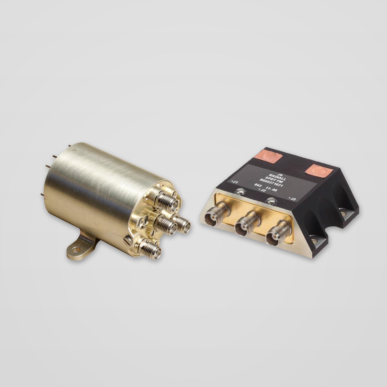
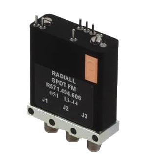
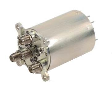
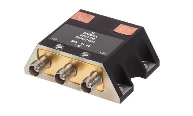
LOW POWER COAXIAL SPDT SWITCH
GENERAL SPECIFICATIONS
Low power latching Coaxial SPDT Switch according to Radiall specification RAD-DET-SPDT-001:
• DC to 22 GHz with SMA connectors
• Up to 31 GHz with SMA 2.9 connectors
• Telemetry circuit
• Suppression diodes
• D-Sub or solder pins
• Lay down or Fixing plate
• 44 grams and up
RF PERFORMANCE DC to 22 GHz SMA
SIMPLIFICATION IS OUR INNOVATION Visit www.radiall.com for more information 7-4 | SPACE
FREQUENCY GHZ DC - 4.2 4.2 - 10.7 10.7 - 12.75 12.75 - 14.5 14.5 - 22 Insertion Loss (max) dB 0 12 0 20 0 25 0 30 0 35 VSWR (max) Return Loss (min) (dB) 1 20 (21) 1 20 (21) 1 20 (21) 1 25 (19) 1 33 (17) Isolation (min) dB 70 65 E-Field Shielding Effectiveness (min) dBi 75 70 Ka – band SMA 2.9 FREQUENCY GHZ 17.5-21.5 21.5 - 27.5 27.5 - 31 Insertion Loss (max) dB 0� 45 0� 45 0� 50 VSWR (max) Return Loss (min) (dB) 1 33 (17 0) 1 35 (16 5) 1 40 (15 6) Isolation (min) dB 65 60 55 E-Field Shielding Effectiveness (min) dBi 70 60 Power Handling (max) W 10 5
UNIT MIN TYPICAL MAX Actuation Voltage V +22 +26 +29 Pick-Up Voltage V - - +20 � 5 Actuation Current mA - -at +29 V, +25 °C - 129 139 at +29 V, -30 °C - 164 176 at +29 V, +85 °C - 105 113 Switching Time ms - - 20 Pulse Duration ms 20 - 1,000 Coil Resistance (at +25 °C) Ω 210 225RF Contact Resistance mΩ - - 100 TLM Indicator Circuit - - -Contact Closed mΩ - - 1,000 Contact Open MΩ 10 10Contact Current mA - - 100 Coil Isolation at 500 VDC MΩ 10 -Dielectric Withstanding at 50 or 60 Hz Vrms 500 -Mass g - -Variant 001-004: SPDT, Fixing Plate, Pins - - 44 Variant 002-005: SPDT, Lay down, Pins - - 62 Variant 003-006: SPDT, Lay down, D-Sub - - 72 Torque Screws for: N m - -Fixing unit - - 2 0 DC connector 0 8 1 1 0 44 SMA connector - - 1�15
Flight Models
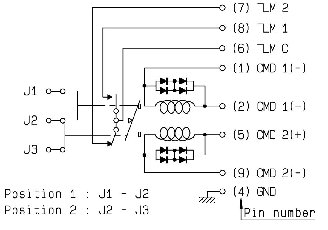
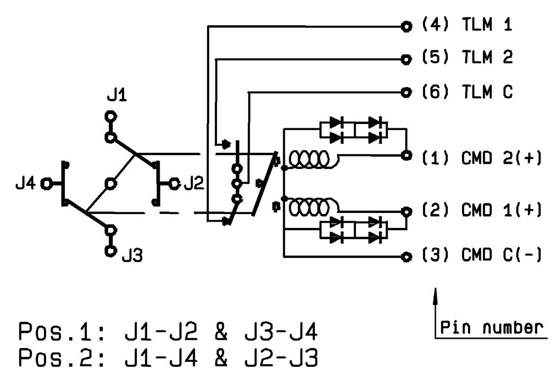
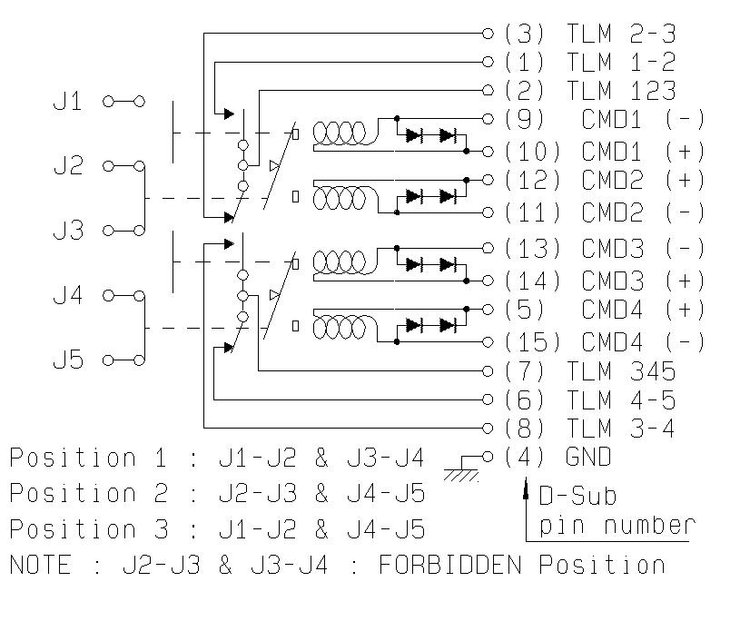
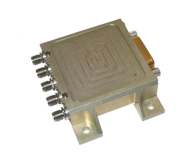
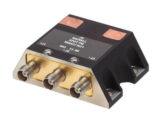
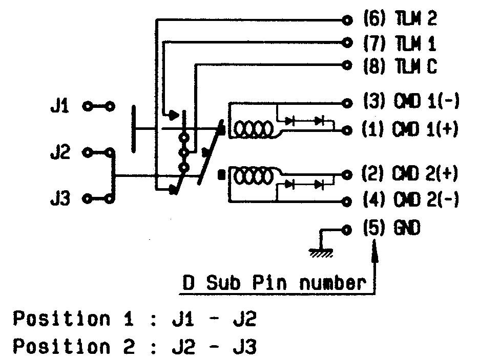
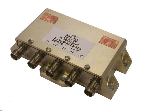
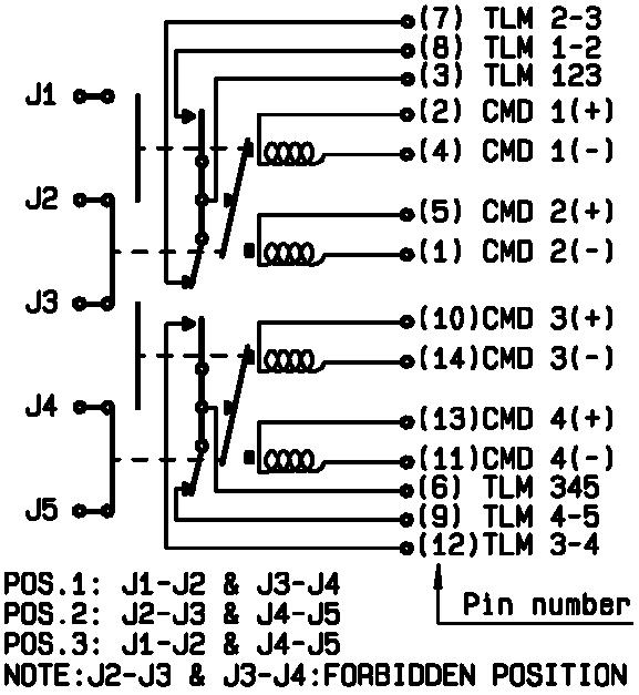
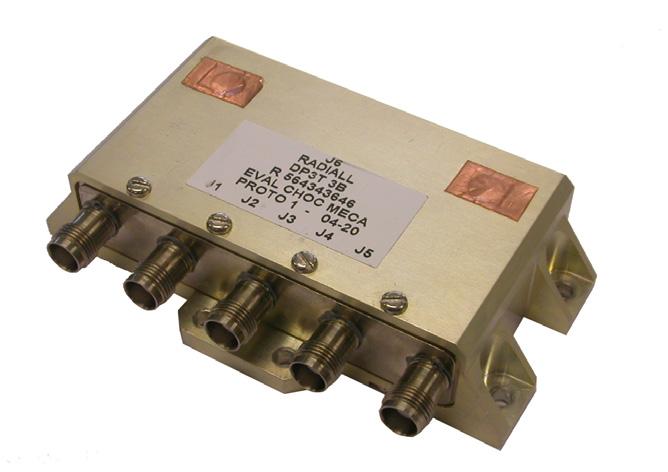
SCHEMATICS & DRAWINGS
SDPT, LAY DOWN, PINS:
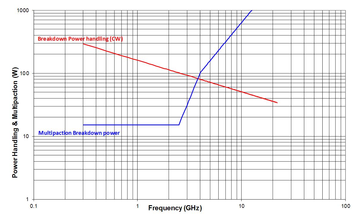
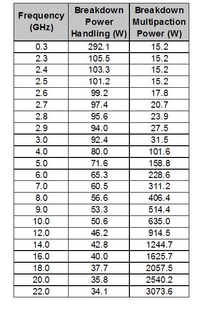
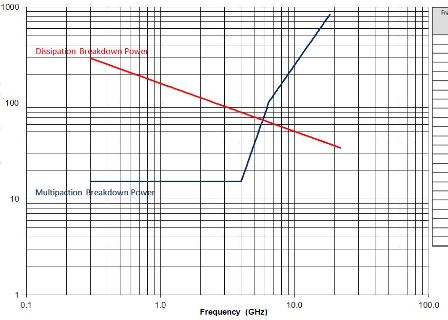
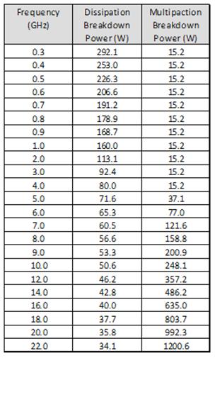
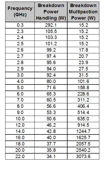
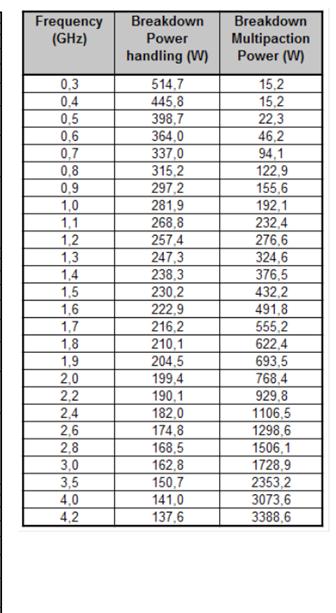
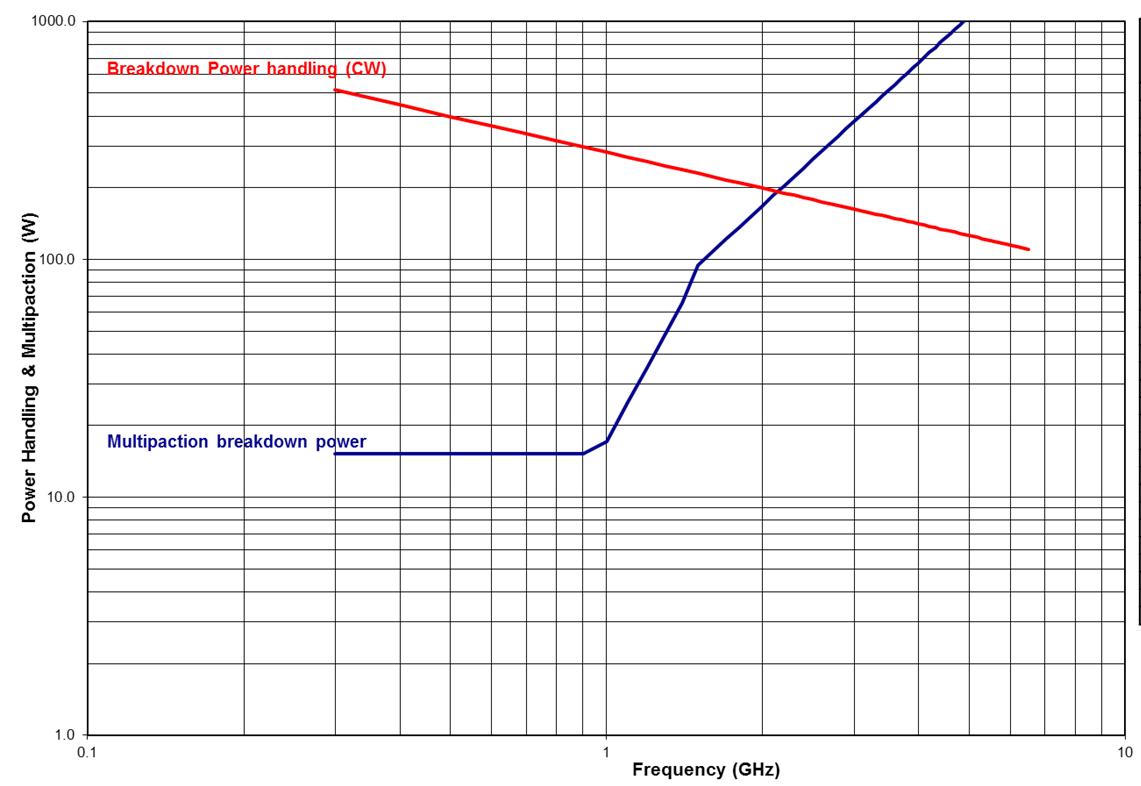
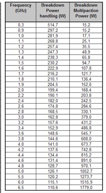
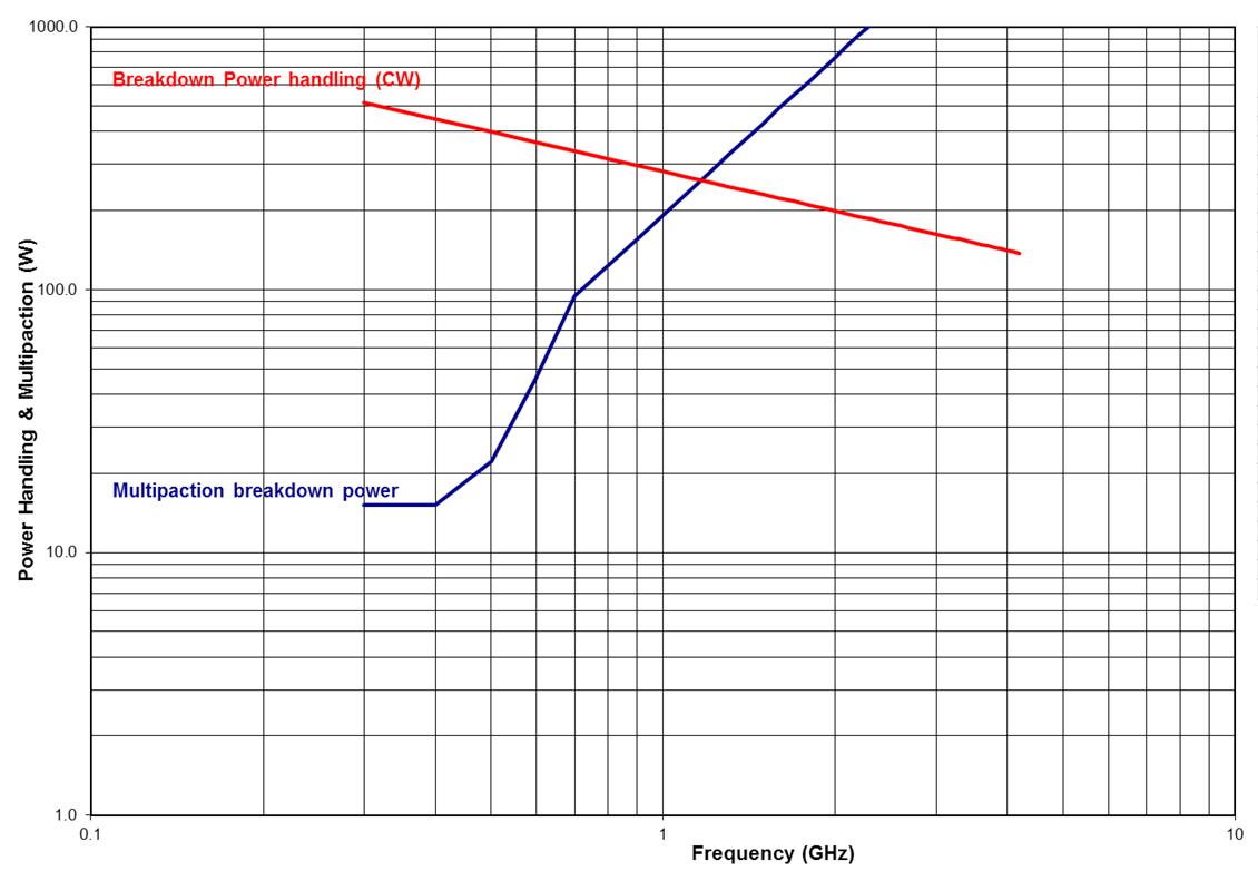
POWER DERATING GRAPH
VARIANT 001 TO 003: DC TO 22 GHz SMA
Power derating versus frequency

SIMPLIFICATION IS OUR INNOVATION Visit www.radiall.com for more information SPACE | 7-5
Frequency (GHz)
Power Handling & Multipaction (W)
SPDT, fixing plate with pins
SPDT, lay down with pins
SPDT, lay down with D-sub
Flight Models
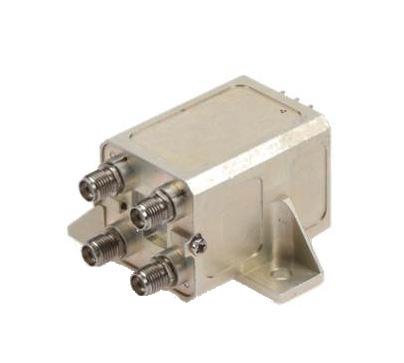
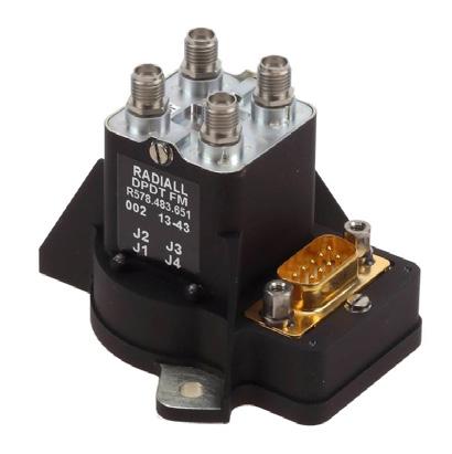
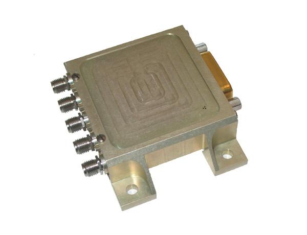
LOW POWER COAXIAL DPDT SWITCH
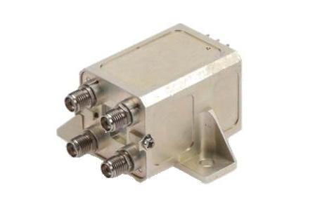
GENERAL SPECIFICATIONS
Low power latching Coaxial DPDT Switch according to Radiall specification RAD-DET-DPDT-006:
• DC to 22 GHz with SMA connectors
• Up to 31 GHz with SMA 2.9 connectors
• Telemetry circuit
• Suppression diodes
• D-Sub or solder pins
• Lay down or Stand up
• 57 grams and up
SIMPLIFICATION IS OUR INNOVATION Visit www.radiall.com for more information 7-6 | SPACE
UNIT MIN TYPICAL MAX Actuation Voltage V +22 +26 +29 Pick-Up Voltage V - - +20 � 5 Actuation Current mA - -at +29 V, +25 °C - 129 139 at +29 V, -30 °C - 164 176 at +29 V, +85 °C - 105 113 Switching Time ms - - 25 Pulse Duration ms 20 - 1,000 Coil Resistance (at +25 °C) Ω 210 225RF Contact Resistance mΩ - - 100 TLM Indicator Circuit - - -Contact Closed mΩ - - 1,000 Contact Open MΩ 10 -Contact Current mA - - 100 Coil Isolation at 500 VDC MΩ 10 -Dielectric Withstanding at 50 or 60 Hz Vrms 500 -Mass g - -Variant 001-005: C-Switch, Stand up D-Sub - - 80 Variant 002-004: C-Switch, Lay down Pins - - 57 Variant 003-006: C-Switch, Stand up Pins - - 63 RF PERFORMANCE DC to 22 GHz SMA FREQUENCY GHZ DC - 4.2 4.2 - 8.4 8.4 - 14.5 14.5 - 18 18 - 20 20 - 22 Insertion Loss (max) dB 0 15 0 25 0 30 0 40 0 50 0 50 VSWR (max) Return Loss (min) (dB) 1 20 (21) 1 25 (19) 1 25 (19) 1 33 (17) 1 33 (17) 1 40 (15 6) Isolation (min) dB 70 65 E-Field Shielding Effectiveness (min) dBi 75 70 68 65 60 Ka – Band SMA 2.9 FREQUENCY GHZ 17.5-21.5 27.5 - 31 Insertion Loss (max) dB 0 50 0 65 VSWR (max) Return Loss (min) (dB) 1 33 (17 7) 1 40 (15 6) Isolation (min) dB 65 60 E-Field Shielding Effectiveness (min) dBi 60 60 Power Handling (max) W 10 5
Flight Models
SCHEMATICS & DRAWINGS
C-SWITCH, SMA, LAY DOWN PINS:
stand up with pins
POWER DERATING GRAPH
VARIANT 001 TO 003: DC TO 22 GHz SMA
lay down with pins
Power derating versus frequency
Power Handling & Multipaction (W)
Frequency (GHz)
SIMPLIFICATION IS OUR INNOVATION Visit www.radiall.com for more information SPACE | 7-7
C-Switch,
C-Switch,
C-Switch, stand up with D-sub
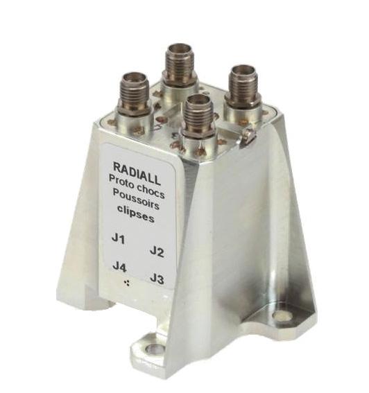
Flight Models
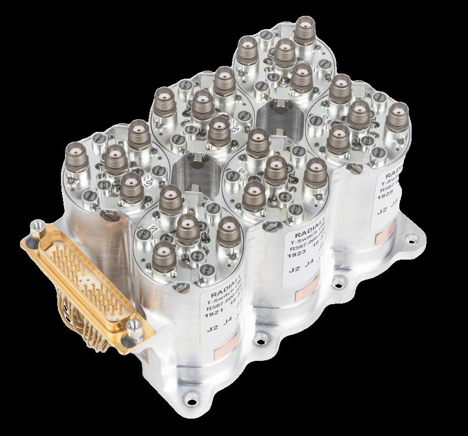
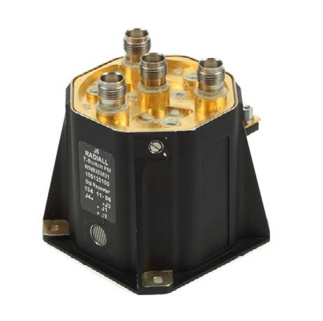
LOW POWER COAXIAL T-SWITCH
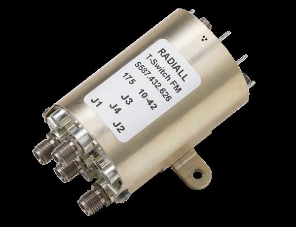
GENERAL SPECIFICATIONS
Low power latching Coaxial Switch according to Radiall specification
RAD-DET-TSSD-002 and RAD-DET-TSRD-003:
• Random or Sequential drive
• DC to 22 GHz with SMA connectors
• Up to 31 GHz with SMA 2.9 connectors
• Telemetry circuit
• Suppression diodes
• D-Sub or solder pins
• Stand up or Lay down or fixing plate
• 58 grams and up
Dielectric
Torque Screws for:
RF PERFORMANCE
DC to 22 GHz SMA
Ka – Band SMA 2.9
SIMPLIFICATION IS OUR INNOVATION Visit www.radiall.com for more information 7-8 | SPACE
FREQUENCY GHZ DC-4.2 4.2-5.5 5.5-6.6 6.6-7.7 7.7-8.8 8.8-10.5 10.5-14.5 14.5-17.8 17.8-20 20-22 Insertion Loss (max) dB 0 15 0 17 0 18 0 21 0 24 0 30 0 35 0 45 0 50 0 50 VSWR (max) Return Loss (min) (dB) 1 20 (21) 1 22 (20) 1 25 (19) 1 25 (19) 1 25 (19) 1 25 (19) 1 25 (19) 1 33 (17) 1 33 (17) 1 40 (15 6) Isolation (min) dB 70 65 E-Field Shielding Effectiveness (min) dBi 75 70 65 65
FREQUENCY GHZ 17.5-21.5 27.5 - 31 Insertion Loss (max) dB 0� 50 0�65 VSWR (max) Return Loss (min) (dB) 1 33 (17) 1 40 (15 6) Isolation (min) dB 65 60 E-Field Shielding Effectiveness (min) dBi 60 60 Power Handling (max) W 10 5
RAD
RAD
DET
TSRD - 003 Random Drive UNIT MIN TYPICAL MAX MIN TYPICAL MAX Actuation Voltage V +22 +26 +29 +22 +26 +29 Pick-Up Voltage V - - +20 5 - - +20 5 Actuation Current mA - - - - -at +29 V, +25 °C - 345 364 - 285 305 at +29 V, -30 °C - 439 462 - 365 390 at +29 V, +85 °C - 280 295 - 234 250 Switching Time ms - - 25 - - 20 Pulse Duration ms 20 - 1,000 20 - 1,000 Coil Resistance (at +25 °C) Ω 79 8 84 - 88 95RF Contact Resistance mΩ - - 100 - - 100 TLM Indicator Circuit - - - - - -Contact Closed mΩ - - 1,000 - - 1,000 Contact Open MΩ 10 - - 10 -Contact Current mA - - 100 - - 100 Coil Isolation at 500 VDC MΩ 10 - - 10 - -
- DET - TSSD - 002 Requential Drive
-
-
Withstanding at 50 or 60 Hz Vrms 500 - - 500 -Mass g - - - - -T-Switch, Lay down Pins - - 73 - - 64 T-Switch, Stand up D-Sub - - 100 - - 100 T-Switch, Stand up Pins - - 75 - - 75 T-Switch, Fixing Plate - - - - - 58
N m - - - - -Fixing unit - - 2 �0 - - 2 �0 D-sub connector 0 27 - 0 44 - - N/A RF connector 0 8 1 1 1 15 0 8 1 1 1 15
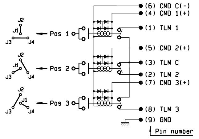
SCHEMATICS & DRAWINGS
SEQUENTIAL DRIVE
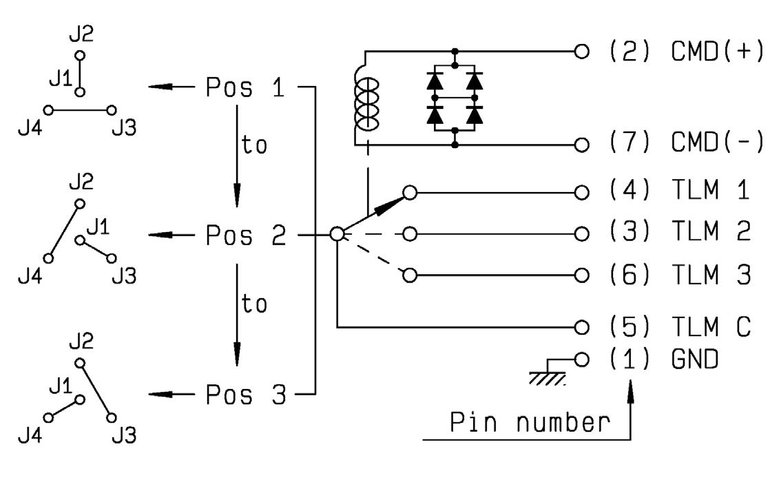
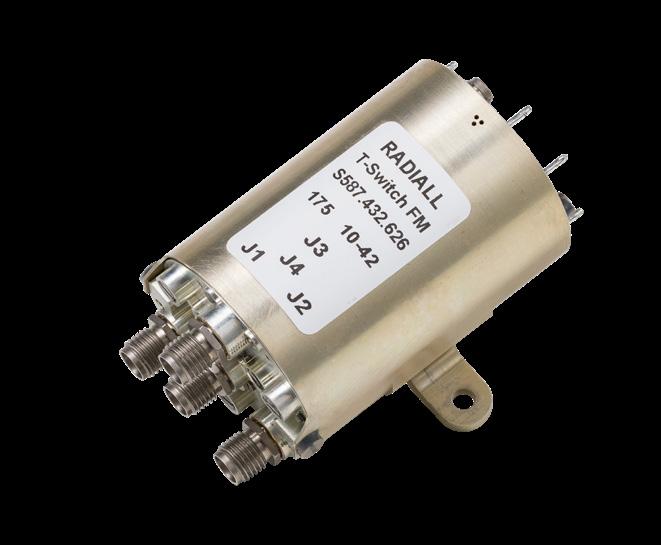
T-Switch, lay down with pins
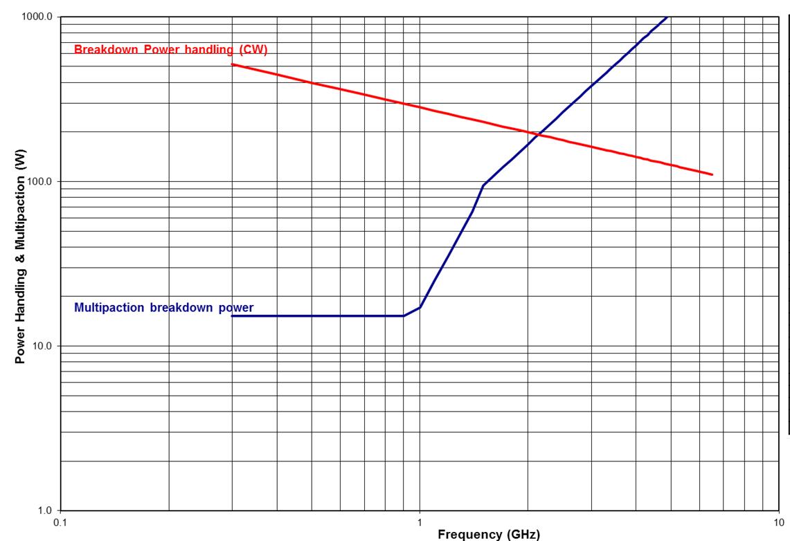
POWER DERATING GRAPH
VARIANT 001 TO 003: DC TO 22 GHz SMA
RANDOM DRIVE
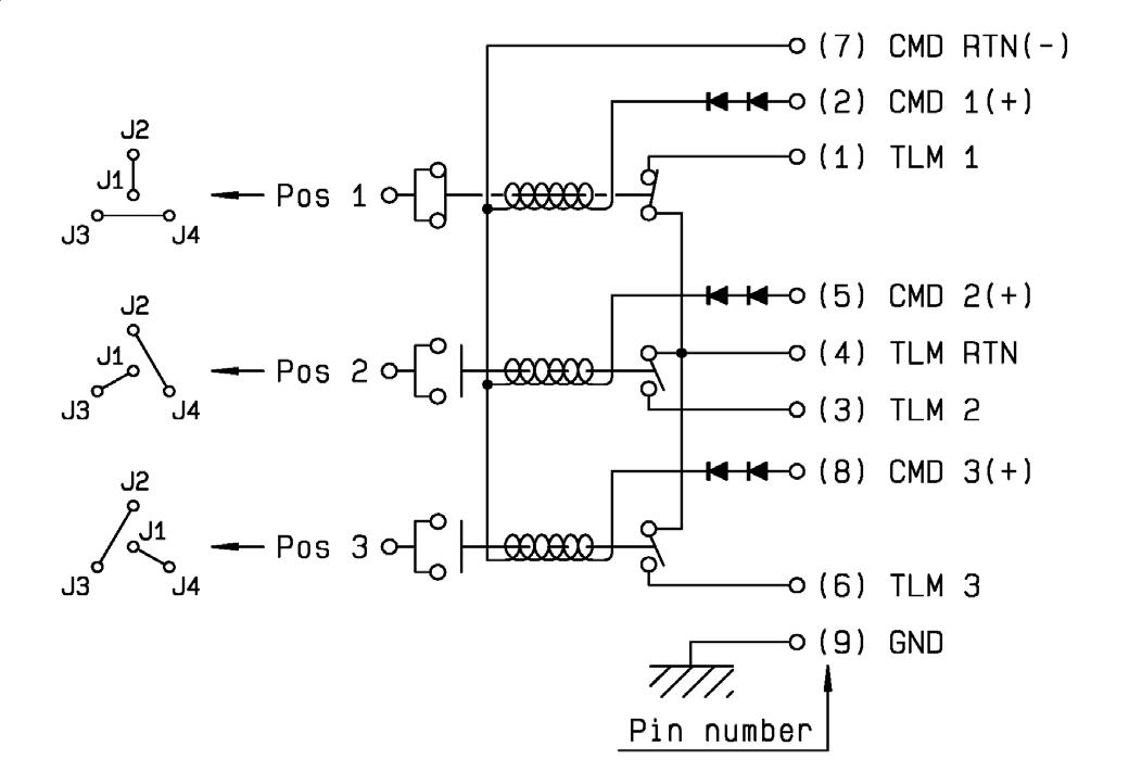
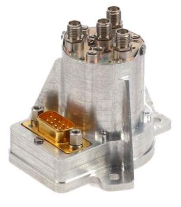
T-Switch, stand up with D-Sub
T-Switch, fixing plate with pins
Handling & Multipaction (W)
Power derating versus frequency Frequency (GHz)
SIMPLIFICATION IS OUR INNOVATION Visit www.radiall.com for more information SPACE | 7-9
Flight Models
Power
Flight Models
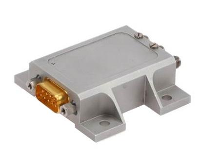
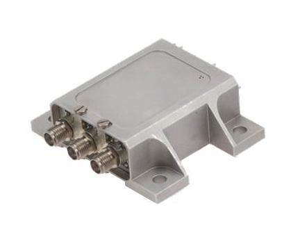
LOW POWER COAXIAL DP3T SWITCH
GENERAL SPECIFICATIONS
Low power latching Coaxial Switch according to Radiall specification RAD-DET-DP3T-001:
• DC to 22 GHz with SMA connectors
• DC to 31 GHz with SMA 2.9 connectors
• Telemetry circuit
• Suppression diodes
RF PERFORMANCE
DC to 22 GHz SMA
Ka – Band SMA 2.9
SIMPLIFICATION IS OUR INNOVATION Visit www.radiall.com for more information 7-10 | SPACE
FREQUENCY GHZ DC - 4.2 4.2 - 10.7 10.7 - 12.75 12.75 - 14.5 14.5 - 22 Insertion Loss (max) dB 0 12 0 20 0 25 0 30 0 35 VSWR (max) Return Loss (min) (dB) 1� 20 (21) 1� 20 (21) 1� 20 (21) 1� 25 (19) 1� 33 (17) Isolation (min) dB 70 65 E-Field Shielding Effectiveness (min) dBi 75 70
FREQUENCY GHZ 17.5-21.5 21.5 - 27.5 27.5 - 31 Insertion Loss (max) dB 0 45 0 45 0 50 VSWR (max) Return Loss (min) (dB) 1 33 (17) 1 35 (16 5) 1 40 (15 6) Isolation (min) dB 65 60 E-Field Shielding Effectiveness (min) dBi 70 60 Power Handling (max) W 10 5
UNIT MIN TYPICAL MAX Actuation Voltage V +22 +26 +29 Pick-Up Voltage V - - +20 5 Actuation Current mA - -at +29 V, +25 °C - 129 139 at +29 V, -30 °C - 164 176 at +29 V, +85 °C - 105 113 Switching Time ms - - 20 Pulse Duration ms 20 - 1,000 Coil Resistance (at +25 °C) Ω 210 225RF Contact Resistance mΩ - - 100 TLM Indicator Circuit - - -Contact Closed mΩ - - 1,000 Contact Open MΩ 10 -Contact Current mA - - 100 Coil Isolation at 500 VDC MΩ 10 -Dielectric Withstanding at 50 or 60 Hz Vrms 500 -Mass g - - 106 Torque Screws for: N m - -Fixing unit - - 2 0 D-sub connector 0 27 - 0 44 RF connector 0 8 1 1 1 15 • D-Sub • Lay
• 106 grams
down
Flight Models
SCHEMATICS & DRAWINGS
POWER DERATING GRAPH
VARIANT 001: DC TO 22 GHz SMA
Power derating versus frequency
DP3T, lay down with D-sub
Power Handling & Multipaction (W)

Frequency (GHz)
SIMPLIFICATION IS OUR INNOVATION Visit www.radiall.com for more information SPACE | 7-11
Flight Models
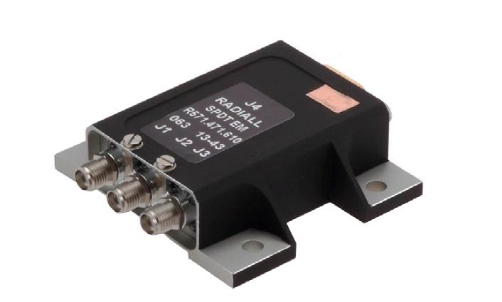
HIGH POWER COAXIAL SPDT SWITCH
GENERAL SPECIFICATIONS
High power latching Coaxial SPDT Switch according to Radiall specification RAD-DET-SPDT-002::
• TNC connectors
• Up to 2.2 GHz, with 160 Watts CW
• Up to 4.8 GHz, with 150 Watts CW
• Telemetry circuit
• Suppression diodes
• D-Sub
• Lay down
• 275
RF PERFORMANCE
SIMPLIFICATION IS OUR INNOVATION Visit www.radiall.com for more information 7-12 | SPACE
DC - 2.2 GHz Variant 001 DC - 4.8 GHz Variant 002 FREQUENCY GHZ 0.04 -1.0 1.0 - 1.6 1.6 - 2.2 0.04 - 1.0 1.0 - 1.6 1.6 - 2.2 2.2 - 4.8 Insertion Loss (max) dB 0 12 0 12 0 22 VSWR (max) Return Loss (min) (dB) 1� 20 (20 8) 1� 20 (20 8) 1� 38 (15 9) Isolation (min) dB 70 E-Field Shielding Effectiveness (min) dBi 70 60
UNIT MIN TYPICAL MAX Actuation Voltage V +20 +26 +30 Pick-Up Voltage V - - +19 Actuation Current mA - -at +29 V, +25 °C 178 188 198 at +29 V, -30 °C 227 239 251 at +29 V, +85 °C 145 153 161 Switching Time ms - 25 35 Pulse Duration ms 50 - 1,000 Coil Resistance (at +25 °C) Ω 152 160 168 RF Contact Resistance mΩ - - 100 TLM Indicator Circuit - - -Contact Closed mΩ - - 1,000 Contact Open MΩ 2 -Contact Current mA - - 100 Coil Isolation at 500 VDC MΩ 1 -Dielectric Withstanding at 50 or 60 Hz Vrms 500 -Mass Variants 001 and 002 g - - 275 Torque Screws for: N m - -Fixing unit - - 2 0 D-sub connector 0 27 - 0 44 RF connector 1 7 - 2 65
g
Flight Models
SCHEMATICS & DRAWINGS
POWER DERATING GRAPH
VARIANT 001, HIGH CAVITY
Power Handling & Multipaction (W)
Power derating versus frequency
lay down with D-sub, variant 001 and 002

VARIANT 002, STANDARD CAVITY
Power Handling & Multipaction (W)
Frequency (GHz)
Power derating versus frequency
Frequency (GHz)
SIMPLIFICATION IS OUR INNOVATION Visit www.radiall.com for more information SPACE | 7-13
SPDT
Flight Models
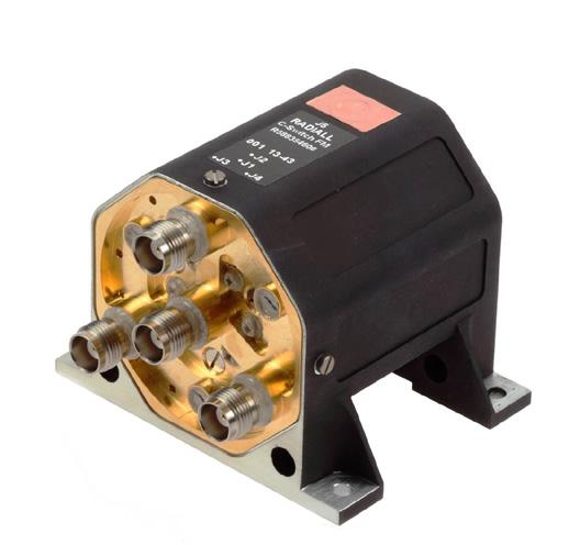
HIGH POWER COAXIAL DP3T SWITCH
GENERAL SPECIFICATIONS
High power latching Coaxial DP3T Switch according to Radiall specification RAD-DET-DP3T-002:
• TNC connectors
• Up to 2.2 GHz, with 160 Watts CW
• Up to 4.8 GHz, with 150 Watts CW
• Telemetry circuit
• Suppression diodes
• D-Sub or pins
• Lay down
• 390 g and up
RF PERFORMANCE
SIMPLIFICATION IS OUR INNOVATION Visit www.radiall.com for more information 7-14 | SPACE
DC - 2.2 GHz Variant 001 DC - 4.8 GHz Variant 002 and 003 FREQUENCY GHZ 0.04 -1.0 1.0 - 1.6 1.6 - 2.2 0.04 - 1.0 1.0 - 1.6 1.6 - 2.2 2.2 - 4.8 Insertion Loss (max) dB 0 12 0 12 0 22 VSWR (max) Return Loss (min) (dB) 1 20 (20 8) 1 20 (20 8) 1 38 (15 9) Isolation (min) dB 70 E-Field Shielding Effectiveness (min) dBi 70 60
UNIT MIN TYPICAL MAX Actuation Voltage V +20 +26 +30 Pick-Up Voltage V - - +19 Actuation Current mA - -at +29 V, +25 °C 178 188 198 at +29 V, -30 °C 227 239 251 at +29 V, +85 °C 145 153 161 Switching Time ms - 25 35 Pulse Duration ms 50 - 1,000 Coil Resistance (at +25 °C) Ω 152 160 168 RF Contact Resistance mΩ - - 100 TLM Indicator Circuit - - -Contact Closed mΩ - - 1,000 Contact Open MΩ 2 -Contact Current mA - - 100 Coil Isolation at 500 VDC MΩ 1 -Dielectric Withstanding at 50 or 60 Hz Vrms 500 -Mass g - -Variant 001: Lay down D-Sub - - 460 Variant 002: Lay down D-Sub Variant - - 445 003: Lay down pins - - 390 Torque Screws for: N m - -Fixing unit - - 2 0 D-sub connector 0 27 - 0 44 RF connector 1�7 - 2 �65
Flight Models
SCHEMATICS & DRAWINGS
POWER DERATING GRAPH
VARIANT 001, HIGH CAVITY
Power Handling & Multipaction (W)
Power derating versus frequency
DP3T, lay down with pins
VARIANT 002, STANDARD CAVITY
Power Handling & Multipaction (W)
Frequency (GHz)
Power derating versus frequency
Frequency (GHz)
SIMPLIFICATION IS OUR INNOVATION Visit www.radiall.com for more information SPACE | 7-15
HIGH POWER COAXIAL T-SWITCH
GENERAL SPECIFICATIONS
High power latching Coaxial T-Switch according to Radiall specification RAD-DET-TSRD-002:
• TNC connectors
• DC to 8 GHz
• Up to 120 Watts CW at 4 GHz
• Random Drive
• Telemetry circuit
• Suppression diodes
• D-Sub or solder pins
• Lay down or Stand up
• 355 grams and up
Variant 001: T-Switch, Lay down, D-Sub
Variant 002: T-Switch, Stand up, D-Sub
RF PERFORMANCE
DC - 8 GHz Variants 001 and 002
SIMPLIFICATION IS OUR INNOVATION Visit www.radiall.com for more information 7-16 | SPACE
FREQUENCY GHZ DC - 2 2 - 4.8 4.8 - 6 6 - 8 Insertion Loss (max) dB 0 17 0 20 0 30 0 40 VSWR (max) Return Loss (min) (dB) 1 10 (26 � 4) 1 25 (19�1) 1 35 (16 � 5) 1 50 (14) Isolation (min) dB 70 E-Field Shielding Effectiveness (min) dBi 75 70 Flight
Models
UNIT MIN TYPICAL MAX Actuation Voltage V +22 +26 +29 Pick-Up Voltage V - - +20 5 Actuation Current mA - -at +29 V, +25 °C 450 470 490 at +29 V, -25 °C 555 585 610 at +29 V, -30 °C 570 595 620 at +29 V, +80 °C 360 385 405 at +29 V, -85 °C 365 380 397 Switching Time ms - - 35 Pulse Duration ms 35 - 1,000 Coil Resistance (at +25 °C) Ω 59 3 61 8 64 4 RF Contact Resistance mΩ - - 100 TLM Indicator Circuit - - -Contact Closed mΩ - - 1,000 Contact Open MΩ 1 -Contact Current mA - - 100 Coil Isolation at 500 VDC MΩ 1 -Dielectric Withstanding at 50 or 60 Hz Vrms 500 -Mass g - - -
- - 360
- - 355
N � m - -Fixing unit - - 2 0 D-sub connector 0 27 - 0 44 RF connector 1 7 - 2 65
Torque Screws for:
Flight Models
SCHEMATICS & DRAWINGS
T-SWITCH, TNC, D-SUB, VARIANT 001 & 002:
T-Switch, Lay down with D-sub, variant 001
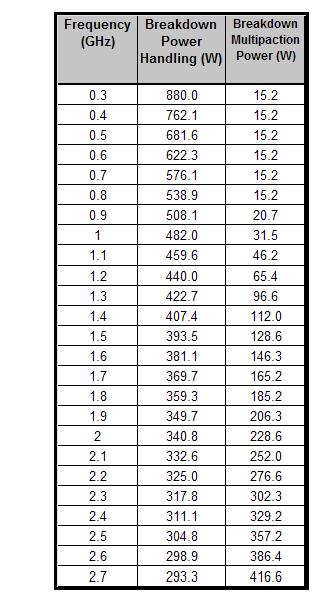
POWER DERATING GRAPH
Power Handling & Multipaction (W)
Power derating versus frequency
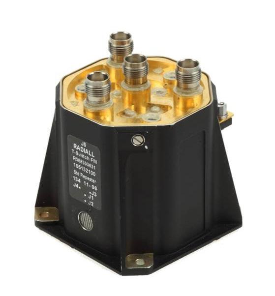
T-Switch, Stand up with D-sub, variant 002
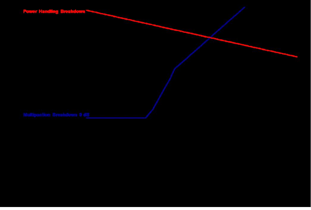
Frequency (GHz)
SIMPLIFICATION IS OUR INNOVATION Visit www.radiall.com for more information SPACE | 7-17
Thermal Vacuum Switches for Ground Segments
GENERAL INFORMATION
PART NUMBER SELECTION
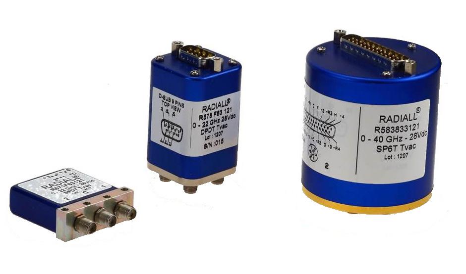
With more than 25 years of experience in the space industry, Radiall has developed a product offering that emphasizes reliability and performance. The latest addition to the range includes SPDT, DPDT and SPnT RF switches designed to operate in thermal vacuum environments. These products can be mounted on ground based test benches, used in test equipment, and space vacuum conditions.
Tvac Series switches are designed in accordance with our standard RAMSES product offering and offer identical configurations with excellent performance
"6 standard models are available for test benches dedicated to space equipment in Thermal Vacuum environments"
• 22 GHz SPDT coaxial switch: R571 F63 121
• 22 GHz DPDT coaxial switch: R578 F63 121
• 22 GHz non-terminated SP6T coaxial switch: R583 F33 121
• 40 GHz SPDT coaxial switch: R571 863 121
• 40 GHz DPDT coaxial switch: R578 863 121
• 40 GHz non-terminated SP6T coaxial switch: R583 833 121
OPERATING MODE
Nominal operating voltage (across operating temperature)
28 (24/30) Coil resistance (+/-10%)
Nominal operating current at 23°
Average power (Thermal vacuum condition)
Switching time (max)
- SMA 2 9
Notes
and SP6T: 225 / SPDT: 350
and SP6T: 125 / SPDT: 80
See power rating chart on page 7-20
and DPDT: 10 ms / SP6T: 15 ms
10 million cycles SMA - SMA 2 9
SMA - SMA 2 �9
2 5 million cycles
5 million cycles / 2 million cycles
Connectors [1] SMA / SMA 2 9
Terminated models are also available SPnT models are only available with separated reset option 1. Connector SMA 2.9 is equivalent to "K connector ®", registered trademark of Anritsu.
SIMPLIFICATION IS OUR INNOVATION Visit www.radiall.com for more information 7-18 | SPACE
LATCHING
Vdc
Ω
DPDT
mA
DPDT
SPDT
SMA
SPDT
DPDT
SP6T
Thermal Vacuum Switches for Ground Segments
ADDITIONAL SPECIFICATION
Actuator terminals
SPDT Solder Pins
DPDT
SP6T
SMA CONNECTOR
Male 9 pins D-Sub connector
Male 25 pins D-Sub connector
Operating temperature range -40 °C to 85 °C
Storage temperature range -55 °C to 85 °C
Construction
SMA 2.9 CONNECTOR
WHY
A
THERMAL VACUUM TEST BENCH?
• It limits the need of hermetic adaptors and cable assemblies
• It improves RF performance
• It decreases the complexity of the Test bench
Notes
1. Average power at 25 °C per RF path / Sea level.
Thermal vacuum compatible
SIMPLIFICATION IS OUR INNOVATION Visit www.radiall.com for more information SPACE | 7-19
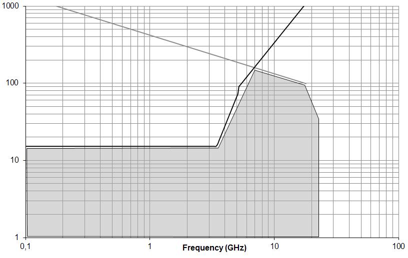
SWITCH MODEL FREQUENCY RANGE GH z V.S.W.R. (MAX) INSERTION LOSS (MAX) dB ISOLATION (MIN) dB IMPEDANCE Ω AVERAGE POWER [1] W REPEATABILITY SPDT DC – 22 DC - 3 1 20 0 20 80 50 240 0.03 dB peak change in Insertion Loss over 100 cycles 3 - 8 1 30 0 30 70 150 8 - 12 4 1 40 0 40 60 120 12 � 4 - 18 1� 50 0� 50 60 100 18 - 22 1�70 0�70 55 40 DPDT SP6T (nonterminated) DC – 22 DC - 3 1 20 0 20 80 50 240 3 - 8 1 30 0 30 70 150 8 - 12 4 1 40 0 40 60 120 12 4 - 18 1 50 0 50 60 100 18 - 22 1 70 0 70 50 40
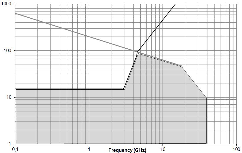
SWITCH MODEL FREQUENCY RANGE GH z V.S.W.R. (MAX) INSERTION LOSS (MAX) dB ISOLATION (MIN) dB IMPEDANCE Ω AVERAGE POWER [1] W REPEATABILITY SPDT DPDT DC – 40 DC - 6 1 30 0 30 70 50 80 0.03 dB peak change in Insertion Loss over 100 cycles 6 - 12 4 1 40 0 40 60 60 12 4 - 18 1 50 0 50 60 50 18 - 26 5 1 70 0 70 55 20 26 5 - 40 1 90 0 90 50 10 SP6T (nonterminated) DC – 40 DC - 6 1 30 0 30 70 50 40 6 - 12 � 4 1� 40 0� 40 60 30 12 4 - 18 1 50 0 50 60 25 18 - 26 5 1 70 0 70 55 15 26 5 - 40 1 90 0 90 50 5
POLARITY POSITIVE COMMON
Thermal Vacuum Switches for Ground Segments
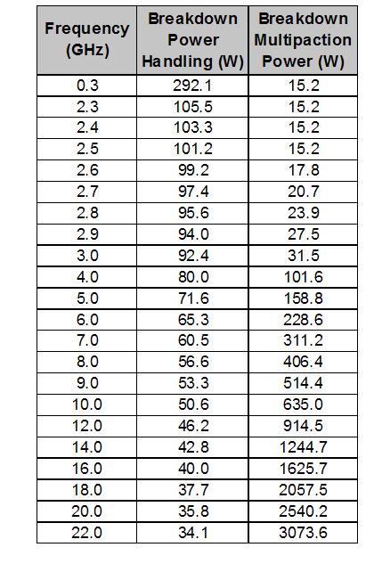
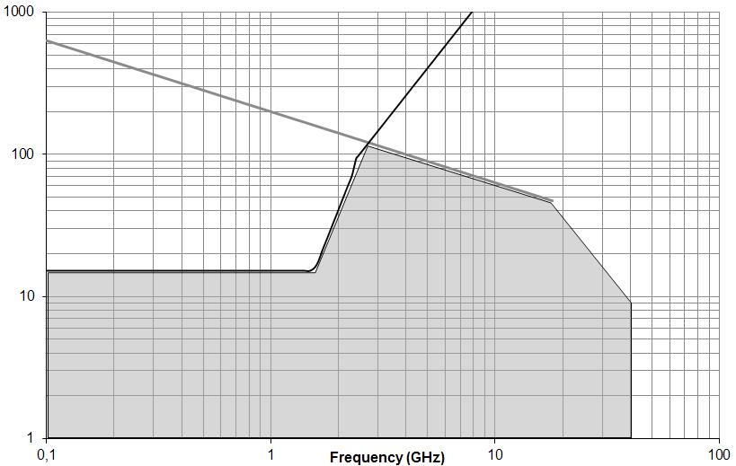
POWER DERATING GRAPH
SPDT, DPDT AND SP6T SMA 22 GHz
Multipactor and Power handling under vacuum (max value)
MultipactorPower handling (W) Frequency (GHz)
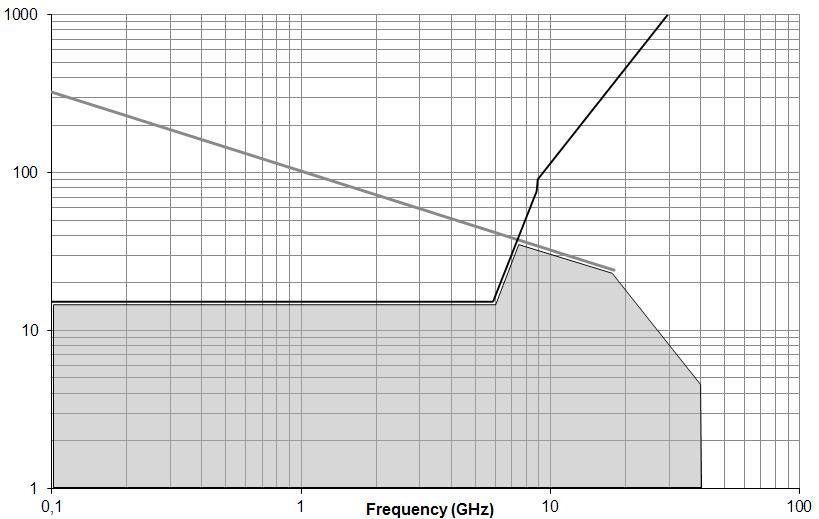
DPDT SMA 2.9 40 GHz
Multipactor and Power handling under vacuum (max value)
MultipactorPower handling (W)
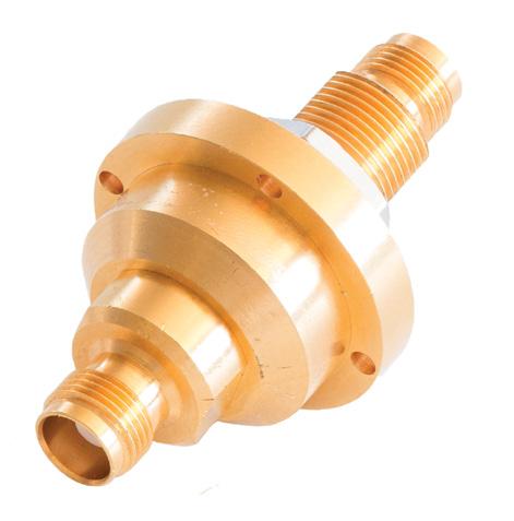
HERMETIC FEMALE/FEMALE ADAPTATORS
SPDT SMA 2.9 40 GHz
Multipactor and Power handling under vacuum (max value)
Multipactor
SP6T SMA 2.9 40 GHz
Multipactor and Power handling under vacuum (max value)
Multipactor
POWER HANDLING
MULTIPACTOR
AVER. POWER CAPABILITY
SIMPLIFICATION IS OUR INNOVATION Visit www.radiall.com for more information 7-20 | SPACE
Power handling (W) Frequency (GHz)
Frequency
(GHz)
Frequency
threshold - -L Band 2 GHz >2000 Wpp Max tested values, pulse width 20 µs; PRF 1,000 Hz C Band 8 GHz >2000 Wpp Power
- -L
GHz 600 WCW -
GHz 400 WCW -
•
Power handling (W)
(GHz) Multipactor
handling
Band 2
C Band 8
•SMA DC - 18 GHz •VHP TNC DC - 8 GHz • E SA qualified
High reliability
