GLOBAL PRESENCE
Recognizing that relationships are rooted in trust, we strive to earn our customers' confidence by demonstrating our market knowledge, technological expertise and experience in each and every interaction.
SALES OFFICES INDUSTRIAL PLANTS
Centr’Alp
L’Isle-d’Abeau
Château-Renault
Shanghai
INTRODUCTION | 3


Active Optics
Our high-performance, optical interconnection brand, D-Lightsys®, provides optical transceiver and electronic solutions suitable for harsh environments.
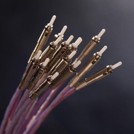
Optical Connectors
Designed for demanding applications where reliability and high performance are required, our cost-effective optical connectors serve telecom, industrial, aerospace and defense markets.
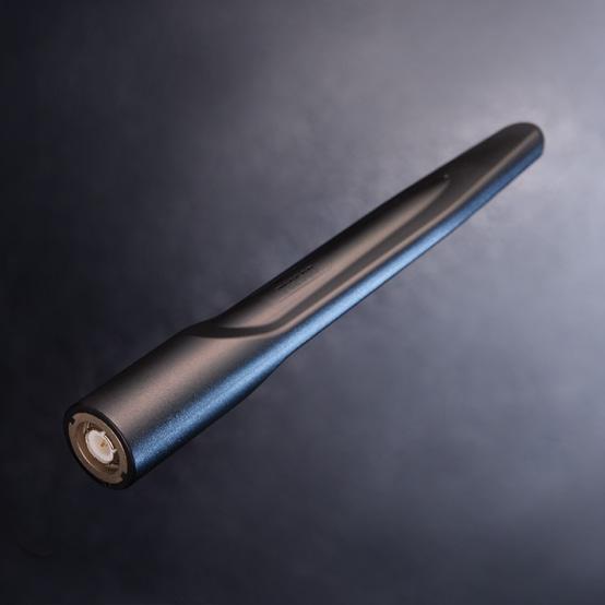
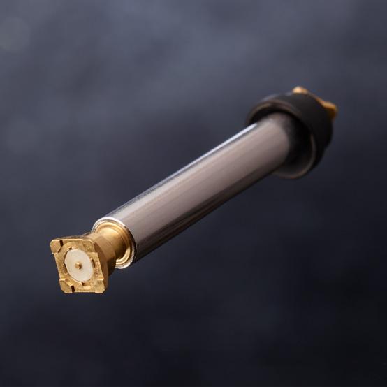
Antennas
With a military and industrial focus, we have solutions for radio tactical communications, vehicles, positioning, LMR/PMR and telemetry applications.

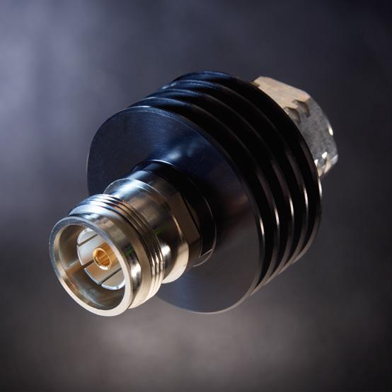
Outdoor Connectors
Designed for outdoor conditions, our range includes high-power RF coaxial connectors, linking antennas and radio units, as well as innovative multi-signal I/O solutions for optical, Ethernet, power or coaxial links between radio and network.
Microwave Components
Our range covers a wide frequency spectrum from DC to 50 GHz, and includes terminations, attenuators, couplers, power dividers, filters and other specialized components.
RF &
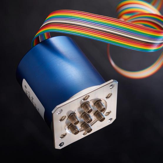
The patented design of our unique, modular actuator and transmission links guarantees operation up to 10 million cycles with superior repeatability.
Microwave Switches
COMPREHENSIVE
4 | INTRODUCTION
PORTFOLIO
At Radiall, we provide a comprehensive portfolio of products that meet the application requirements of the key industries we serve. By listening to our customers, we continuously develop new solutions and update our extensive range of products.
With over sixty years of experience and an understanding of the ever-changing business and our customers' technical requirements, we deliver the optimal and most cost-effective, end-to-end interconnect solutions available today.

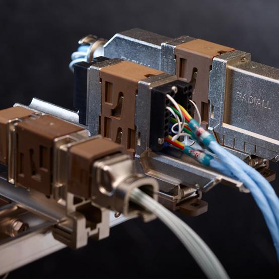
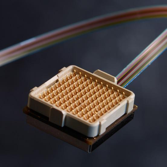
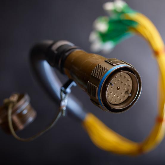
Multipin Aerospace Connectors
For more than 40 years, commercial airframes have trusted our range of rack and panel connectors and modular solutions. Our new miniature connector series combines high performance and reduced weight to meet civil and military aerospace industry demands.
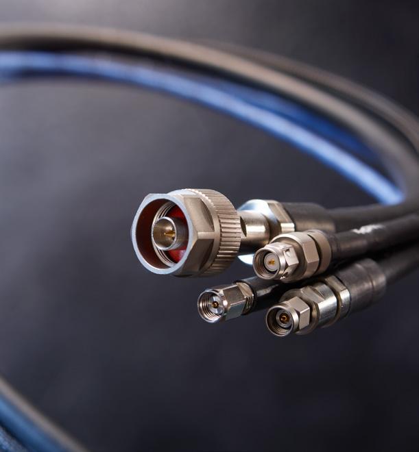
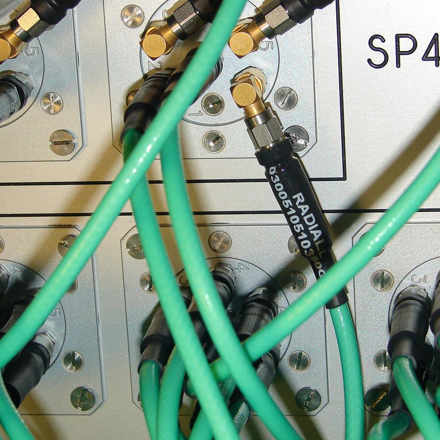
RF Cable Assemblies
Low-loss and high-frequency characterize our extensive range of cable assemblies, including flexible, semi-rigid and hand-formable solutions with a broad combination of cables and connectors.

Multipin Industrial Connectors
Our Van-System brand designs and produces a range of robust circular electrical connectors suitable for harsh environments, such as railways, machine tools, and plant engineering equipment.
RF Coaxial Connectors
We offer the widest range of RF coaxial connectors in the industry; 55 product series are available, including AEP and Mil QPL connectors.
Optical Cable Assemblies
Our extensive product range and worldwide presence supports customers with standard configurations as well as optimized solutions based on customer requirements.

Space Qualified Components
Known for high quality as well as reliability and performance, our product offering includes a wide range of coaxial connectors, cable assemblies, microwave components and switches with a frequency range up to K a band.
INTRODUCTION | 5
SIMPLIFICATION IS OUR INNOVATION Visit www.radiall.com for more information NOTES 1 | INT RODUC TION
SIMPLIFICATION IS OUR INNOVATION Visit www.radiall.com for more information SECTION 1
INFORMATION
TECHNICAL
TECHNICAL INFORMATION | 1-1 SIMPLIFICATION IS OUR INNOVATION Visit www.radiall.com for more information INTRODUCTION Coaxial Switches Activity Information 1-2 to 1-6 Manufacturing and Quality Assurance Flow ������������������������������������������������������������������������������������������������������������������������� 1-7 RAMSES Concept 1-8 to 1-9 RF Arrangement ���������������������������������������������������������������������������������������������������������������������������������������������������������������������� 1-10 Glossary (including RF Power Rating Chart page 1-13) ������������������������������������������������������������������������������������������ 1-11 to 1-12 RF Repeatability and Life Test Parameters 1-15 Conversions ���������������������������������������������������������������������������������������������������������������������������������������������������������������� 1-16 to 1-20 User Handbook 1-21 Applications ����������������������������������������������������������������������������������������������������������������������������������������������������������������������������� 1-22
Section 1 Table of Contents
Introduction
COAXIAL SWITCHES ACTIVITY INFORMATION EXPERIENCE
With over 60 years of experience and continuous efforts in R&D, Radiall has become Europe’s number one source for coaxial connectors. Radiall’s position as a market leader has enabled the company to excel in the passive microwave component field for more than 50 years. Radiall’s expertise in design, development and manufacturing of passive microwave components is widely acknowledged in today’s industry.
A WIDE RANGE OF SOLUTIONS
Specialized in passive microwave components, Radiall’s design team and engineering staff manufactures a wide range of standard coaxial devices including: terminations, attenuators, couplers, coaxial detectors and coaxial switches covering a frequency range from DC to 50 GHz.
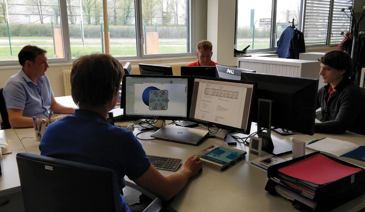
RESEARCH & DEVELOPMENT
Due to the increased complexity of microwave systems, more high performance components are required
To meet these requirements, Radiall’s R&D department is constantly working on development of new products and improvement on existing products �
Equipped with microwave and mechanical CAD and the latest generation of microwave test equipment up to 60 GHz, Radiall uses state-of-the-art technology to optimize products and quickly respond to specific customer requests �
CAPACITIES & FACILITIES
Radiall’s global presence and worldwide facilities offer expertise in the following: marketing, research and development, industrialization, manufacturing and quality control This strong heritage enables Radiall to produce a range of high performance and low cost devices for industrial applications, and high reliability components for severe requirements in military and space markets


1-2 | TECHNICAL INFORMATION Visit www.radiall.com for more information
Head office - Aubervilliers France
COAXIAL SWITCHES ACTIVITY INFORMATION PRODUCTION
Electrical performance of microwave products is determined by machining quality of individual piece parts and associated plating Equipped with computer-controlled machinery, and an in-house plating department, Radiall is able to manufacture high quality piece parts that are compatible with existing components �
Due to the thick and thin film etching equipment, Radiall’s production department guarantees the quality of the resistive cells used in most terminated switching products A prototype workshop allows Radiall to quickly respond to special customer request �
All the phases of manufacturing and test are strictly inspected by our quality department, so as to warrant the constancy of our products and to achieve general and specific requirements.
Radiall’s quality department inspects products through all phases of manufacturing and testing, to ensure consistency to all products for customer satisfaction�
QUALITY, RELIABILITY & PATENTS
Radiall’s main focus for passive microwave components are quality and reliability� EN 9100:2009 label is the best evidence of quality assurance interfaces at every stage of a product from designing to manufacturing
All new products are subject to a rigid qualification program before massive production begins. Additionally, product quality is reviewed and tested periodically�
NATO CODE
Radiall is a qualified microwave components manufacturer under military label (manufacturer code F0503 and F6507), and offers quality assurance developed in accordance with N A T O standards
T ECHNICAL INFORMATION | 1-3 SIMPLIFICATION IS OUR INNOVATION Visit www.radiall.com for more information
Introduction
Introduction
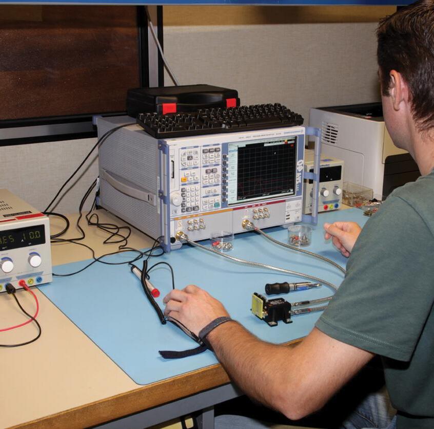
COAXIAL SWITCHES ACTIVITY INFORMATION A TESTING LABORATORY
As an illustration of Radiall’s commitment to quality and reliability, Radiall has an in-house test laboratory qualified by CECC which permits Radiall to complete the majority of tests required by customers
PARTIAL LIST OF TEST MEANS
Electrical
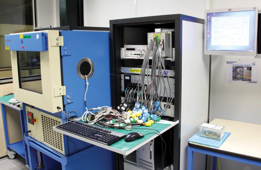
Environmental
Vibrations: Sine random
Shakes
1-4 | T ECHNICAL INFORMATION SIMPLIFICATION IS OUR INNOVATION Visit www.radiall.com for more information
12
Insulation resistance 40
Contact
1
Microwave Breakdown voltage
K Volts
10 3 M Ohms
resistance
μ Ohms
0
- 120 g; 5 to 4,000 Hz Shocks 30 to 1,000 g
25
ms
vacuum 10 -5 TORR; -45 to +100 °C
shock -70 °C +200 °C / transfert 20 s Storage temperature -70 °C to +200 °C Humidity 20 to 98% HR Salt
-35 °C to +55 °C
Helium 10 -5 to 10 -8 atm cm 3 /s V� S �W� R � insertion loss Isolation Vector Network Analyzer From 0�01 up to 70 GHz RF Leakage / EMC Reverberation chamber method 0 5 to 40 GHz / Noise 100 dB Power Handling 400 W CW 0 8 up to 2 GHz 200 W CW 2 up to 4 GHz 20 W CW 8 up to 18 GHz 2,000 Wpp 1 up to 2.5 GHz 2,000 Wpp 2.5 up to 8 GHz
to 40 g 6
Thermal
Thermal
Spray
Hermeticity
Introduction
COAXIAL SWITCHES ACTIVITY INFORMATION CAPABILITIES
Radiall offers a wide variety of coaxial switches to answer customer needs. This catalog is intended to be used as a guide in selecting the right type of switch for a given application It is important to note that Radiall is not limited to catalog products and has the flexibility to design a specific product on a tight schedule at a reasonable cost. Radiall is always available to discuss specific customer requests.

RELIABILITY
Radiall’s coaxial switches offer exceptional reliability and performance. A unique patented design of the actuator and transmission link enables Radiall to guarantee operation up to 10 million cycles for Terminated SPnT and other series as well — with excellent repeatability�

LIST OF APPLICABLE DOCUMENTS
List of related documents covering the general mechanical and environmental tests applicable to the devices described in this catalog.
7304
47295
93561
93562
T ECHNICAL INFORMATION | 1-5 SIMPLIFICATION IS OUR INNOVATION Visit www.radiall.com for more information
AIR
NFC
MIL C 39012 DIN
NFC
MIL E 5400 NFC
NFC
MIL STD 202 NFC
MIL DTL
154 IEC
93563
93564
96317
3928
Introduction
COAXIAL SWITCHES ACTIVITY INFORMATION
GENERAL SPECIFICATIONS DESIGNED TO MEET MIL DTL 3928 & MIL STD 202
ENVIRONMENTAL CHARACTERISTICS
VIBRATIONS METHOD 204 10 - 2,000 Hz 10 g Operating
SHOCKS METHOD 213 50 g, 1/2 sine Non-operating
MECHANICAL CHARACTERISTICS, MATERIAL & FINISHED
RF BODY
CONTACTS
INSULATOR
Aluminium, Gold-plated Aluminium, Nickel-plated Aluminium with Cr3 passivation
Beryllium Copper, Gold-plated
PTFE, ULTEM 1,000
CONNECTORS Stainless stess, passivated brass, Nickel-plated
CONSTRUCTION Splash proof
COVER Aluminium, blue anodized
MANUFACTURING & QUALITY ASSURANCE
Radiall’s RF switches product line is made of approximately 20 series of switches, with each series divided into a large number of configurations. Part numbers consist of 9 digits, each digit designating a portion of the part's actual identity (such as series, frequency, actuator voltage, etc.).
For each digit, 2 to 10 options are available. A complete part number represents a unique configuration.
Overall, there are more than 80,000 different configurations available with very few subassemblies due to the modularity of the RAMSES switching line (less than 300 different subassemblies).
A Push-Pull manufacturing process has been implemented to reduce both lead time and inventory� Based upon marketing forecast and monthly updates, various subassemblies are manufactured.
When an order is received, an automated MRP system selects the appropriate subassemblies from stock to manufacture the requested products within a short time frame (a few days to a few weeks) depending on the complexity of the product �
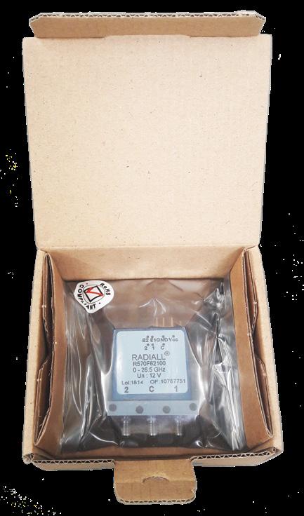
PACKAGING
All our coaxial switches are packed in a Korrvu packaging For electromagnetic sensitive switches we also use ESD packet.
TRACEABILITY
All our coaxial switches are equipped with a barcode for better traceability� Titanium and Platinum series switches are also equipped with a serial number�
These requirements are guaranteed according to MIL standard — see applicable product section to get more accurate and detailed information.
All materials and finishes are in accordance with applicable MIL and NF specifications. All connectors are in accordance with applicable MIL, DIN, NF and CEI specifications. All dimensions in this catalog are given in millimeters. The non specified dimensions are given within +/- 0.5 mm.

Radiall has adopted the process management philosophy of "Lean Manufacturing." This process enables the best possible price and lead times on coaxial products by eliminating unnecessary stages of the administrative processes. The lean manufacturing concept was first applied to the RAMSES SPDT and SP6T non-terminated coaxial products and is now being expended over all coaxial switches.
1-6 | TECHNICAL INFORMATION SIMPLIFICATION IS OUR INNOVATION Visit www.radiall.com for more information
Introduction
MANUFACTURING & QUALITY ASSURANCE FLOW
QUALITY
Incoming parts
• Components
• Mechanical parts
• Electrical parts
Incoming Inspection
• Sampling based on MIL STD 105 and Radiall Quality Manual
Manufacturing of subassemblies
RF subassemblies
100% RF test at subassembly level
Stock
Actuator subassemblies
100% testing for actuator strength and stroke by automatic test bench
Stock of subassemblies
Pre-cap visual inspection
• List of key verification points with photographic referential
• Monthly indicators displayed for continuous improvement
Encapsulation, marking and lot identification
Burn-in and acceptance tests on automatic test equipment:
• 2,500 actuations at minimum voltage during a complete operating temperature cycle
• Monitoring of RF contact resistances and indicator contact resistances throughout the testing process
• Monthly indicators about test results displayed for continuous improvement
Visual Inspection
Final assembly of switches
Manufacturing pushed by Marketing
Manufacturing pulled by order
T ECHNICAL INFORMATION | 1-7 SIMPLIFICATION IS OUR INNOVATION Visit www.radiall.com for more information
Stock
RAMSES CONCEPT
An innovative system has been designed for constructing electromechanical coaxial RF switches with increased long-term reliability. Radiall’s Modular System for Electromechanical Switches (RAMSES) is a patented concept that enables microwave coaxial switches to be produced with a typical operating life of 10 million cycles while suffering no decrease in contact resistance reliability over time. In addition, the unique internal construction makes the switches cost-competitive with traditional switches �
FRICTION EFFECTS
The unique design of RAMSES is based on the reduction of friction, which minimizes particle deposits that can interfere with the transmission of lower frequency signals (up to 3 GHz)
This particle elimination effect is particularly important for telecommunication applications that are currently in the 900 MHz and 2 GHz range. In addition, the design involves fewer components compared to other microwave switches, making it quick and easy to assemble.
These savings directly relate to lower cost for improved performance Many of the existing coaxial electromechanical switches also are able to function mechanically for 10 million operations
However, the reliability and quality of the electrical contact can decrease over the life cycle
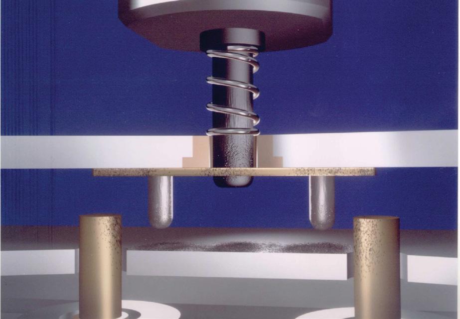
In general, these traditional switches operate by moving a rectangular switching blade section inside a rectangular cavity� The blades are linked with pushers constructed of dielectric material that travel inside an access hole between the RF cavity and switch actuator� The pushers are directed by dielectric material guides � These dielectric parts rub on the blades and inside the access hole and generate isolating particles in the RF cavity that pollute the electrical contacts and ultimately cause running defects
Figure 1 shows the build-up of minute dielectric particles on a set of conventional switch contacts after one million cycles � These defects are not particularly noticeable at very high frequencies since the contact is established by a capacitive effect. However, the insertion loss of the contacts increases considerably at lower frequencies (3 GHz below)
1-8 | T ECHNICAL INFORMATION SIMPLIFICATION IS OUR INNOVATION Visit www.radiall.com for more information
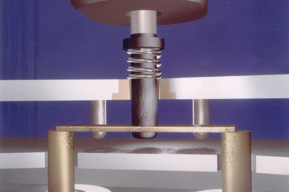
(a) RF line open
FIG. 1: CONVENTIONAL SWITCH CONTACTS AFTER ONE MILLION CYCLES
Introduction
(b) RF line closed
RAMSES CONCEPT
A NEW ACTUATOR CONFIGURATION
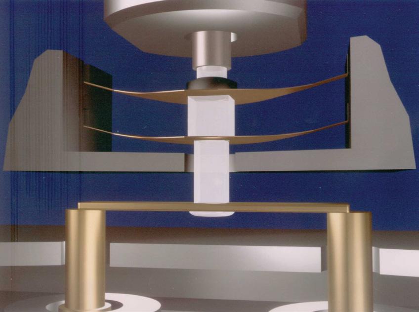
To eliminate this problem of increased insertion loss in the contacts, RAMSES devices incorporate a patented system. This system, compresses two parallel blades suspended from a bearer, which enables the guiding and positioning of the commutation blades to be accomplished entirely outside the RF cavity. These blades impose a rectilinear motion on the switching pusher, suppressing both friction and the production of particles inside the RF cavity. The unique system is extremely small and can be used in all of RAMSES series switches.
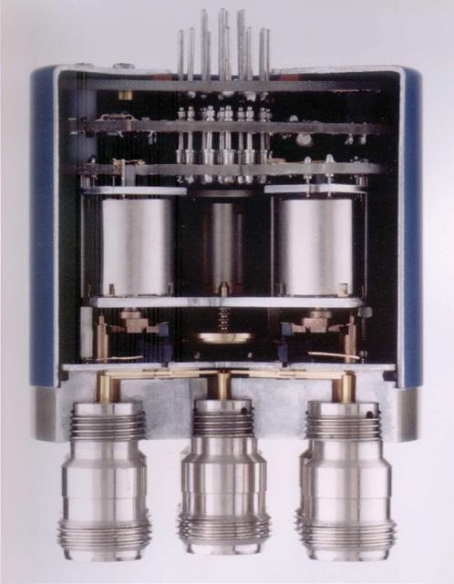
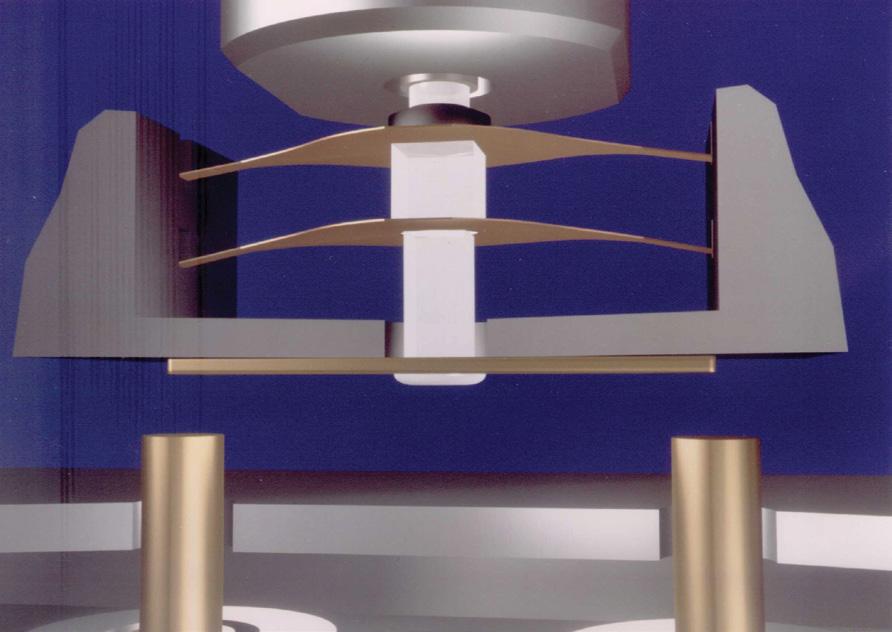
Figure 2 shows a cutaway view of a RAMSES coaxial switch displaying the actuator mechanism A second improvement involves a new rectilinear actuator design using high energy magnets and a switching performance in relation to its size�
The system is used in the production of both failsafe and latching actuators, depending on how it is applied in the switch. These actuators are either 500 g locking forces or 300 to 800 g current forces for a power consumption of 100 mA at 28 V
The new actuator has the added advantage of very low magnetic leakage, allowing actuators to be used in close proximity to one another without performance degradation� The use of a dry, solid lubricant and the control of friction areas provide an actuator life expectancy of over 50 million operations without defect when temperature range exceeds -40 ° to +85 °C �
SWITCH PERFORMANCE
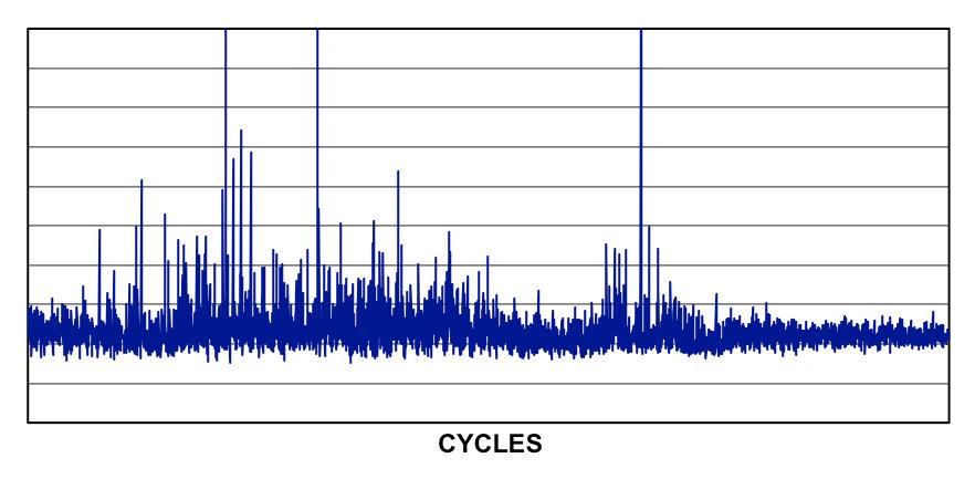
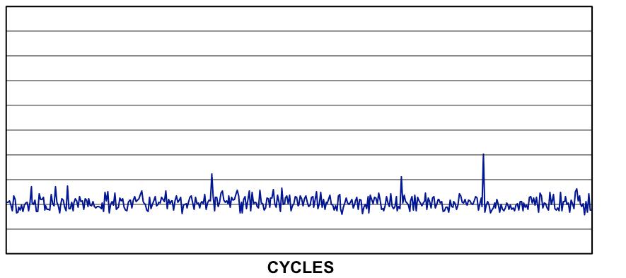
RAMSES series switches have successfully survived tests of 10 million switching temperature cycles from -55 ° to + 85 °C while demonstrating good contact resistance stability� Visual inspection of these switches after testing has indicated that the RF lines were free of much of the contamination found during similar tests on traditional switches � A comparison of the actual measured contact resistance obtained from monitoring both conventional and RAMSES switches using several parts that have already been actuated one million cycles is shown in figure 4. Although the conventional switch may not be considered failure, its contact resistance has become unstable, thus degrading its reliability.
T ECHNICAL INFORMATION | 1-9 SIMPLIFICATION IS OUR INNOVATION Visit www.radiall.com for more information
(a) RF line open
FIG. 2: CUTAWAY VIEW
FIG. 3: A RAMSES SET OF CONTACTS
(b) RF line closed
FIG. 4: A COMPARISON OF (A) CONVENTIONAL & (B) RAMSES SWITCH DESIGN CONTACT RESISTANCE DURING ONE MILLION CYCLES
Introduction
Introduction
RF ARRANGEMENT
COAXIAL SPDT SWITCH (Single Pole Double Throw)
• A switch with one input port and two selectable output ports �
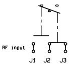
COAXIAL DP3T SWITCH (Double Pole Three Throw)
• A switch with two input ports and three output ports Each input (J2 - J4) can be switched between two adjacent outputs with one output being common to both inputs
COAXIAL MULTIPOSITION SWITCH (Single Pole n Throw - n<13)
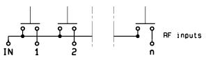
• A switch with one input port and more than two output ports The multiposition switch allows direct access to any individual output port by energizing the respective actuator� Radiall SPnT switches provide up to 12 output ports
COAXIAL SPDT TERMINATED SWITCH (Single Pole Double Throw Terminated)
• Same as SPDT, but the unused output port is automatically terminated by a 50 Ohm resistive load�
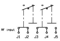
COAXIAL DPDT SWITCH (Double Pole Double Throw)
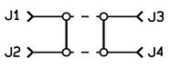
• A four port switch with two independent paths that operate simultaneously in one of two selected positions. In a DPDT/Transfer switch, the two transmission paths are provided as shown above
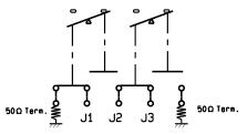
COAXIAL MULTIPOSITION TERMINATED SWITCH (Single Pole n Throw Terminated - n<13)
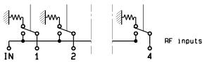
• Same as SPnT, but each unused output port is automatically terminated in an internal 50 Ohm resistive load�
1-10 | T ECHNICAL INFORMATION SIMPLIFICATION IS OUR INNOVATION Visit www.radiall.com for more information
Introduction
GLOSSARY
Actuator Voltage: All RAMSES series relays are either 12 or 28 Vdc nominal voltage over the entire temperature range� The switches can be operated with a voltage between -15 % and +10 % of the nominal value� Other voltage as 5, 15 or 24 Volts can be supplied at the customer’s request.
Automatic “Reset”: All Latching version multiposition switches (or SPnT) cause the following scenario:
When a RF path is closed, it remains in the closed position after the voltage is cut-off (latching function). To switch to another path, the first path must be opened via a “RESET” driver, followed by the closing of the second RF path. Without the “RESET” driver, both paths would remain in the ON position at the same time.
To simplify the use of latching products, an “automatic RESET” is recommended. The auto reset feature is accomplished by an electronic circuit which brings about the automatic opening of a previously closed path during changes of position of the switches
This option produces a higher current consumption during a few milliseconds (see voltage and current values listed on the product’s individual technical data sheet).
BCD (BINARY CODE DECIMAL) DRIVER INTERFACE
BCD LOGIC CODING RF AND MICROWAVE WAYS POSITION
0 0 0 0
0 0 0 0
0
0
0
0
0 1 0 1
1 0 0 0
1 0 0 1
1
1
Latching models: all ways in "OFF" position
Normally Open models: memory of last position
Way IN - 1 in "ON" position
Way IN - 2 in "ON" position
Way IN - 3 in "ON" position
Way IN - 4 in "ON" position
Way IN - 5 in "ON" position
Way IN - 6 in "ON" position
Way IN - 7 in "ON" position
Way IN - 8 in "ON" position
Way IN - 9 in "ON" position
Way IN - 10 in "ON" position
Way IN - 11 in "ON" position
Way IN - 12 in "ON" position
Normally Open models: all ways are in "OFF" position
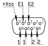
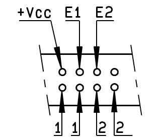
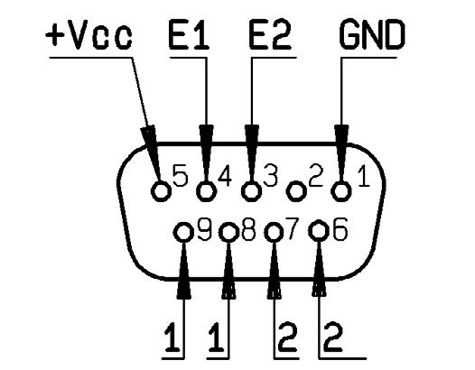
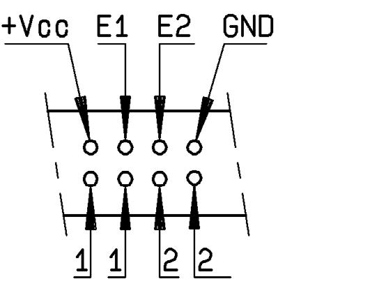
E1, E2, E3, E4 are BCD driver pins of the product. E4 applies only with 8 positions or more. E3 applies only 4 positions or more.
Break-Before-Make: Radiall coaxial relays are considered “break-before-make”. In a break-before-make product the contact of the first path leaves its state before the final contact has been established.
Failsafe: A switch with an actuator that contains a return mechanism, either mechanical or magnetic, that provides RF connection to one selected position when no voltage is applied to the power terminals� This type of switch requires continuous voltage to maintain RF connection to any other position
Frequency Range: The frequency range for each device indicates the maximum frequency Radiall will guarantee for the products performance�
Indicator Contacts: Electrical contacts of an “open circuit, short-circuit” type, mechanically linked to the actuator and synchronized with switched RF paths, ensure the recopy of positions of RF transmission paths. When a microwave path is switched, the corresponding indicator contact is closed. It is generally used with pilot lamps to indicate position of RF contacts (characteristics are given for a resistive load)
T ECHNICAL INFORMATION | 1-11 SIMPLIFICATION IS OUR INNOVATION Visit www.radiall.com for more information
E4 E3 E2 E1
0 0 1
0 1 0
0 1 1
0
1 0
0 1 1 0
0 1 1 1
0
0 1
0 1 1
0 0
1 1
1 1 1 1
Introduction
GLOSSARY (CONTINUED)
Intermodulation (PIM): or intermod for short, is a form of signal distortion that occurs whenever signals of two or more frequencies are produced in a passive device which contains nonlinear response� This interference includes low contact pressure, dirty interconnects, magnetic materials or other anodic effect. The typical value for Radiall switches is around 120 dBc, except for SMT relays which is 110 dBc (with 2 carriers at +43 dBm), however products can be designed for higher performance upon request
Isolation: The RF leakage from a connected path to any connector outside that path Isolation is measured in decibels below the input power�
Latching: A switch with an actuator that contains a mechanism, either mechanical or magnetic, that will maintain a chosen RF contact path (whether voltage is maintained or not) after switching is accomplished� A pulse length of a duration equal to the maximum switching time is enough to change the switch position
Life: Number of toggles a product is able to carry out. Relays and switches of RAMSES, PLATINUM and TITANIUM ranges have a life cycle of 2 to 10 million cycles �
Normally Open: A mode of operation in which all output ports of the switch are disconnected from the input port until a voltage is applied to a selected position�
SWITCHES FAMILY
RAMSES SPDT SPDT = R570 D-Sub (male) 9 pins
Available only on products described on page 2-16
PLATINUM SPDT SPDT = R595 D-Sub (male) 9 pins Non-terminated models
RAMSES DPDT DPDT = R577 D-Sub (male) 9 pins
TITANIUM DPDT DPDT = R513 HE10 ribbon receptacle (male) 10 pins
PLATINUM DPDT DPDT = R593
Delivered with ribbon cable 750 mm (30 inches) + HE10 connector (female)
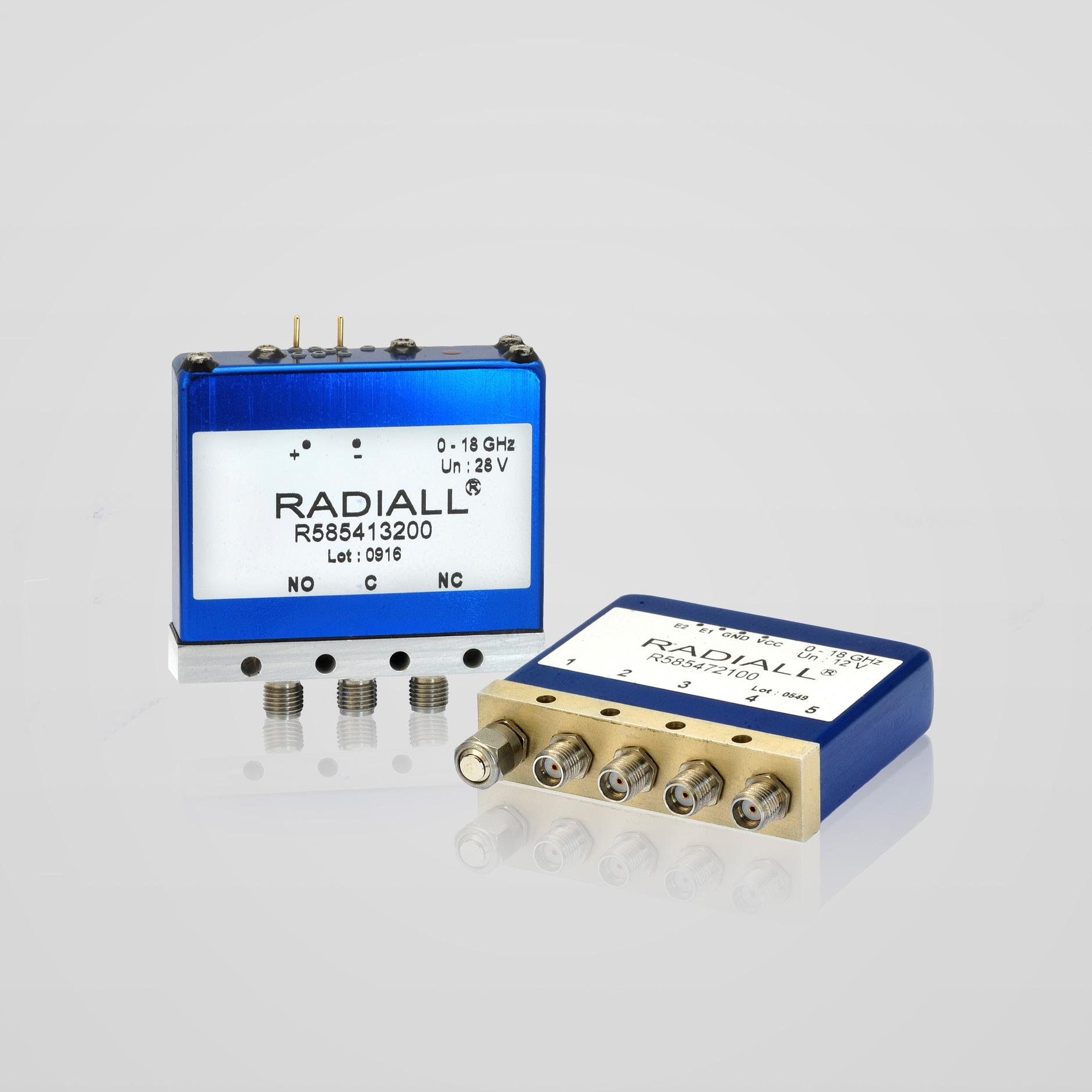
RAMSES DP3T [1] DP3T = R585 N/A Only solder pins
PLATINUM DP3T [1] DP3T = R595 D-Sub (male) 9 pins -
RAMSES & Subminiature SPnT
SPnT = R573/R574 3 to 10 positions and 12 positions D-Sub (male) 25 pins44 pins High density
SPnT = R591 4 and 6 positions Micro-D receptacle (female) 9 pins
TITANIUM SPnT SPnT = R514 4 and 6 positions HE10 ribbon receptacle (male) 16 pins
PLATINUM SPnT SPnT = R594 4 and 6 positions
Notes 1. Terminated RAMSES and PLATINUM SPDT are included in R585 and R595.
Delivered with ribbon cable 750 mm (30 inches) + HE10 connector (female)
1-12 | T ECHNICAL INFORMATION SIMPLIFICATION IS OUR INNOVATION Visit www.radiall.com for more information
PIN
TYPE OF
NUMBER COMMENTS SERIES CONNECTOR
-
-
Introduction
GLOSSARY (CONTINUED)
Polarity: A common negative polarity is chosen by Radiall for its standard products An inverted polarity (common plus) is available on RAMSES range; contact Radiall for availability�
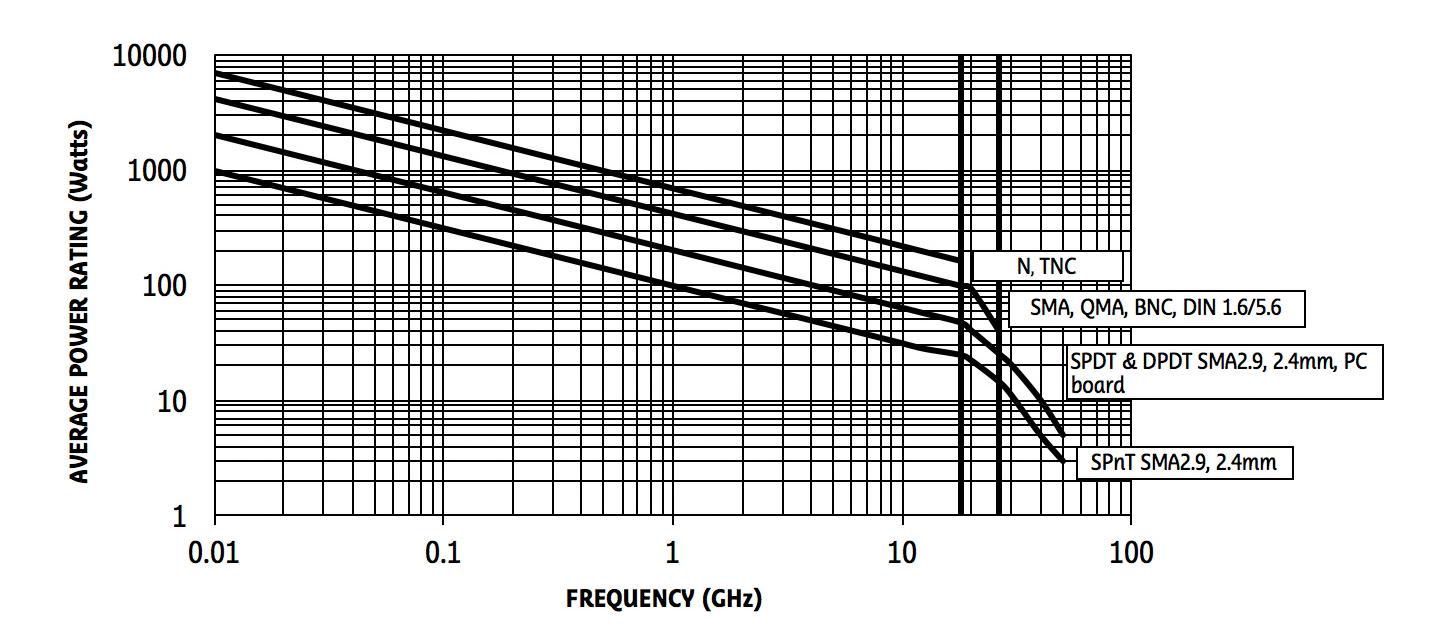
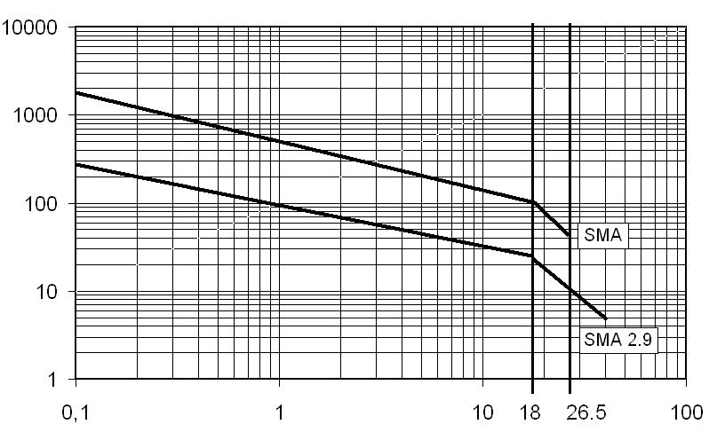
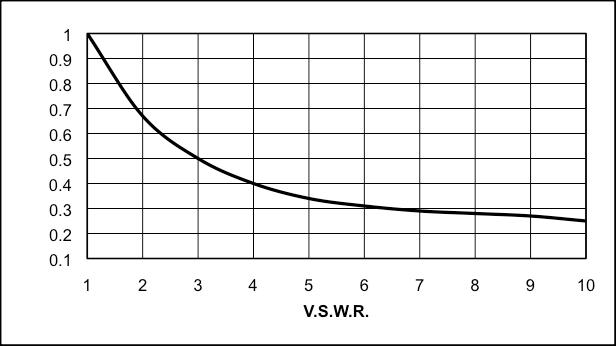
RF Power Chart: The RF power rating is the capability of handling RF power (CW power) through closed contacts � The RF power should be removed during switching� Power ratings assume unity V� S �W� R � (matched load) at room temperature (25 °C), sea level pressure (14.7 p.s.i.) and cold switching. See below the CW power capability vs. Frequency Chart. Changes in these specifications require power derating (see derating factor versus V.S.W.R.).
This graph is based on the following conditions:
• Ambient temperature: +25 °C
• Sea Level
• V.S.W.R.: 1:1 and cold switching
Derating Factor: The average power input must be reduced for load V S W R above 1:1
FACTOR
Notes For PLATINUM and TITANIUM series, common plus polarity potential is chosen for its standard products.
T ECHNICAL INFORMATION | 1-13 SIMPLIFICATION IS OUR INNOVATION Visit www.radiall.com for more information
0.1 0.2 0.3 0.4 0.5 0.6 0.7 0.8 0.9 1 1 2 3 4 5 6 7 8 9 10 V.S.W.R. DERATING
Introduction
GLOSSARY (CONTINUED)
Peak Power Handling: The maximum peak power, when applied at room temperature under a pulse of one microsecond every millisecond, will not permanently change the specifications of the switch. Power applied over this limit will alter the RF performance of the switch�
Repeatability: The maximum standard deviation in insertion loss specifications on each path over the life of the product. Insertion loss repeatability is specified for all PLATINUM series (0.03 dB over 10 million) and all TITANIUM series (0 03 dB over 2 5 million)
RF Connectors: RF connectors are 50 or 75 Ohms female, unless otherwise specified. The applicable mating dimensions, materials and finish are in accordance with applicable sections of international standard (MIL C 39012, DIN 47295). NB RADIALL 75 Ohm coaxial switches are only available with DIN 1.6/5.6 (screw, snap and slide connector) and mini SMB RF connectors
Self Cut-Off: The ability of a switch to disconnect the actuator voltage as soon as the switching of the position is carried out. The system applies to latching relays and is achieved with solid state circuitry. Self Cut-Off time for our RAMSES coaxial switches is from 40 ms to 120 ms �
Solder Pin: RAMSES relays are equipped with solder pins for the control and indicator contacts � The maximum temperature during soldering should not exceed 250 °C for 30 seconds or 300 °C for 10 seconds for lead-free soldering process
Suppression Diodes: Diodes connected in parallel with the coil of a switch to suppress transient voltage generated by the self inductance of the coil during the driver signal cut-off. This option is systematically enclosed in all TTL, SELF CUT-OFF and all electronic interfaces �
Switching Time: The total amount of time between applying voltage to the actuator terminals and the completion of switching (including all contact bounce — if any). Total switching time consists of three parts, namely inductive delay in the actuator coil, transfer time of the RF contacts, and bounce time of the RF contacts.
TTL Driver Interface: The interface of an electronic circuit which enables driving either relays or switches by TTL logic signals � Products equipped with this option have a pin for the voltage of the actuator (12 V or 28 V) as well as a TTL driver pin shared per position� The polarity is not relevant to applications for switches with this option� The logic used is positive, therefore high level nominal +5 V (2.2 to 5.5 V) of TTL signal means logic “1” which enables the corresponding microwave way. Low level i.e logic contacts 0, voltage is 0-0.8 V. Selected position of switches with TTL driver are controlled by a TTL high level�
V.S.W.R.: The Voltage Standing Wave Ratio is a measure of the return loss or level of the reflected signal of a device connected on a transmission line. V.S.W.R. is linked to the coefficient of reflection (r) by the equation:
VSWR = 1+/r/ 1-/r/ r = Z-Zo Z+Zo
V.S.W.R. varies from 1 to ∞, a value equal to 1 represents a perfect matching where:
• “r” is the coefficient of reflection.
• “Zo” is the characteristic impedance of the line.
• “Z” is the impedance of the line.
1-14 | T ECHNICAL INFORMATION SIMPLIFICATION IS OUR INNOVATION Visit www.radiall.com for more information
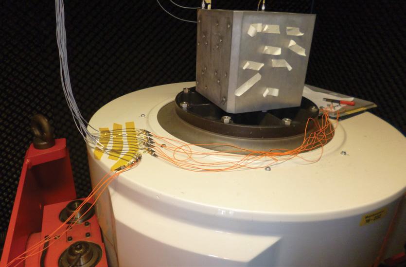
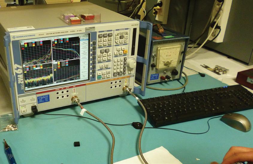
RF REPEATABILITY & LIFE TEST PARAMETERS
Radiall has built an Automatic Test Bench composed by a Vector Network Analyzer (VNA), Digital Multi-Meters (DMM), PC and a switch driver� This approach is to qualify over the complete life of the switch (2� 5 million to 10 million cycles depending on switch models)� This ATE extracts and stores the RF parameters or contacts resistances of the switch according to our own internal procedure. For each frequency point a calculation of VSWR, insertion loss and standard deviation are computed All measurements are performed at room temperature (RF switch is toggled at 3 Hz)
The curves in 3D illustrate the RF characteristics over 10 million switching cycles on SP6T-26.5 GHz RAMSES switch.
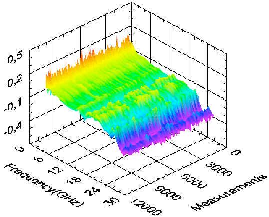
Insertion loss over 10 million cycles
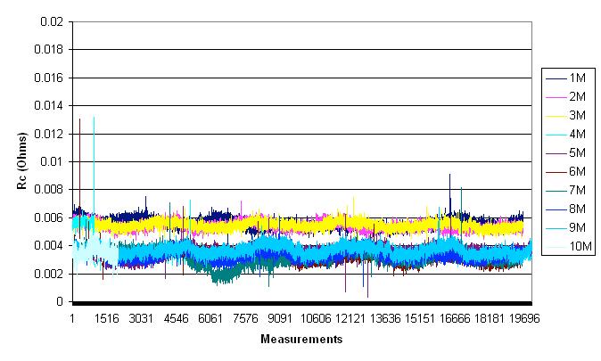
The contribution due to only Rc can be calculated as follows:
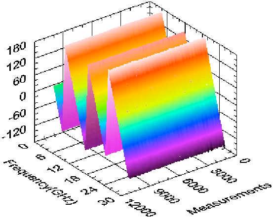
Phase over 10 million cycles
The following curve shows RF contact resistance up to 10 million� Switch was toggled at 3Hz with Rc recorded each 50 cycles �
T ECHNICAL INFORMATION | 1-15 SIMPLIFICATION IS OUR INNOVATION Visit www.radiall.com for more information
L RL =20 LOG 10 | | = 20 LOG 10 Rc 2 Ro + Rc IL = 10 LOG 10 Ro Ro + Rc
= 1+ Rc Ro
VSWR
Introduction
Introduction
CONVERSIONS
CONVERSION MEASUREMENT UNIT
•
•
• Convert kilogram to pounds: 1 kg = 2.20 Lb/1 lb = 0.45 kg
REFLECTION COEFFICIENT RETURN LOSS CONVERSION
• Reflection coefficient (ρ)
• Standard wave ratio (1 + ρ) / (1 - ρ)
• Return loss (dB) (-20 log10 ρ)
1-16 | T ECHNICAL INFORMATION SIMPLIFICATION IS OUR INNOVATION Visit www.radiall.com for more information REFLECTION COEFFICIENT V.S.W.R. RETURN LOSS (dB) REFLECTION COEFFICIENT V.S.W.R. RETURN LOSS (dB) 0 1 00 ∞ 0 195 1 48 14 2 0 01 1 02 40 0 0 2 1 5 14 0 0 015 1 03 36 5 0 205 1 52 13 8 0 02 1 04 34 0 0 21 1 53 13 6 0 025 1 05 32 0 0 215 1 55 13 4 0 03 1 06 30 5 0 22 1 56 13 2 0 035 1 07 29 1 0 225 1 58 13 0 0 04 1 08 28 0 0 23 1 6 12 8 0 045 1 09 26 9 0 235 1 61 12 6 0 046 1 10 26 7 0 24 1 63 12 4 0 05 1 11 26 0 0 245 1 65 12 2 0 055 1 12 25 2 0 25 1 67 12 0 0 06 1 13 24 4 0 255 1 68 11 9 0 065 1 14 23 7 0 26 1 7 11 7 0 07 1 15 23 1 0 265 1 72 11 5 0 075 1 16 22 5 0 27 1,74 11 4 0 08 1 17 21 9 0 275 1 76 11 2 0 085 1 19 21 4 0 28 1,78 11,1 0 09 1 20 20 9 0 285 1 80 10 9 0 095 1 21 20 4 0 29 1 82 10 8 0 1 1 22 20 0 0 295 1 84 10 6 0 105 1 23 19 6 0 3 1 86 10 5 0 11 1 25 19 2 0 305 1 88 10 3 0 115 1 26 18 8 0 31 1 90 10 2 0 12 1 27 18 4 0 32 1 94 9 9 0 125 1 29 18 1 0 33 1 99 9 6 0 13 1 30 17 7 0 34 2 03 9 4 0 135 1 31 17 4 0 35 2 08 9 1 0 14 1 33 17 1 0 36 2 13 8 9 0 145 1 34 16 8 0 37 2 17 8 6 0 15 1 35 16 5 0 38 2 23 8 4 0 155 1 37 16 2 0 39 2 28 8 2 0 16 1 38 15 9 0 4 2 33 8 0 0 165 1 4 15 7 0 41 2 39 7 7 0 17 1 41 15 4 0 42 2 45 7 5 0 175 1 42 15 1 0 43 2 51 7 3 0�18 1� 44 14 �9 0� 44 2 � 57 7�1 0�185 1� 45 14 �7 0� 45 2 �64 6 �9
1� 47 14 � 4 0� 5 3 �00 6 �0
0�19
Convert inch to millimeters: 1 in = 25.4 mm/1 m = 39.3 in
Convert centimeters to feet: 1 ft = 30.40 cm/1 m = 3.28 ft
Introduction
POWER CONVERSION
dBm = 10 × Log10 P (milliwatts) P (milliwatts) = 10^ (dBm/10)
T ECHNICAL INFORMATION | 1-17 SIMPLIFICATION IS OUR INNOVATION Visit www.radiall.com for more information POWER (dB m) POWER (W) POWER (dB m) POWER (W) -49 0.01 μW 1 1 26 mW -48 0.02 μW 2 1 58 mW -47 0.02 μW 3 2 00 mW -46 0.03 μW 4 2 � 51 mW -45 0.03 μW 5 3 �16 mW -44 0.04 μW 6 3 98 mW -43 0.05 μW 7 5 01 mW -42 0.06 μW 8 6 31 mW -41 0.08 μW 9 7 94 mW -40 0.10 μW 10 10 mW -39 0.13 μW 11 12 59 mW -38 0.16 μW 12 15 85 mW -37 0.20 μW 13 19 95 mW -36 0.25 μW 14 25 12 mW -35 0.32 μW 15 31 62 mW -34 0.40 μW 16 39� 81 mW -33 0.50 μW 17 50�12 mW -32 0.63 μW 18 63 10 mW -31 0.79 μW 19 79 43 mW -30 1 μW 20 100 mW -29 1.26 μW 21 125 89 mW -28 1.58 μW 22 158 49 mW -27 2 μW 23 199 53 mW -26 2.51 μW 24 251 19 mW -25 3.16 μW 25 316 23 mW -24 3.98 μW 26 398 11 mW -23 5.01 μW 27 501�19 mW -22 6.31 μW 28 630�96 mW -21 7.94 μW 29 794 33 mW -20 10 μW 30 1 W -19 12.59 μW 31 1 26 W -18 15.85 μW 32 1 58 W -17 19.95 μW 33 2 W -16 25.12 μW 34 2 51 W -15 31.62 μW 35 3 16 W -14 39.81 μW 36 3 98 W -13 50.12 μW 37 5 01 W -12 63.10 μW 38 6 � 31 W -11 79.43 μW 39 7�94 W -10 100.00 μW 40 10 W -9 125.89 μW 41 12 59 W -8 158.49 μW 42 15 85 W -7 199.53 μW 43 19 95 W -6 251.19 μw 44 25 12 W -5 316.23 μW 45 31 62 W -4 398.11 μW 46 39 81 W -3 501.19 μW 47 50 12 W -2 630.96 μW 48 63 10 W -1 794.33 μW 49 79 43 W 0 1 mW 50 100 W
CONVERSIONS (CONTINUED) Introduction
TEMPERATURE EQUIVALENCE
Temp (°C) = (( °F - 32 ) x 5 )) / 9
Temp (°F) = (( 9 x °C ) / 5) + 32
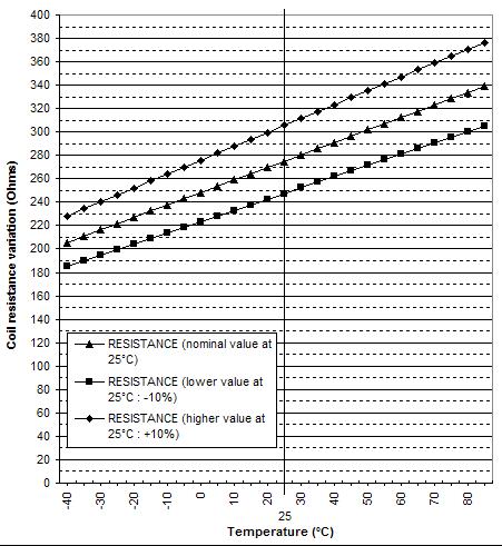
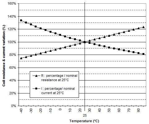
DERATING TEMPERATURE INFORMATION
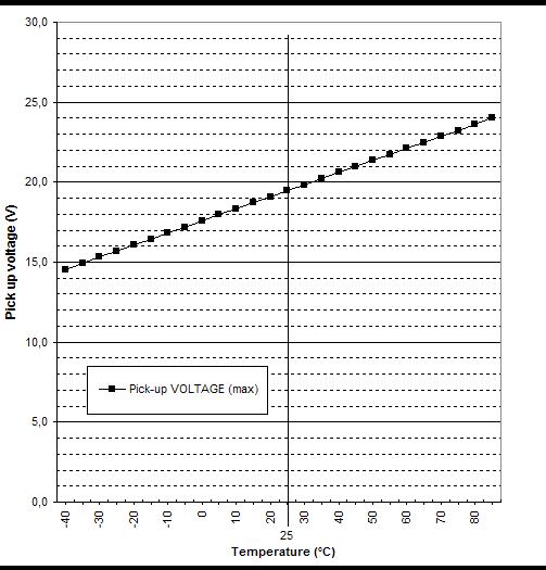
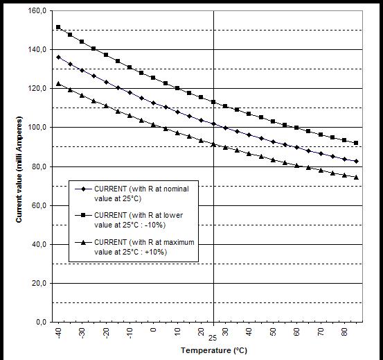
The temperature at which the switches are used has an effect on the coil resistance. This is due to the temperature and variation of the resistivity of copper and the pick up voltage
Formula of the variation of coil resistance versus the temperature is:
• R’ = R (1 + K (t’ – t))
• K = Temperature coefficient (0.0038 for copper)
• R = Coil resistance (ohms) at temperature t ( °C)
• R’ = Coil resistance (ohms) at temperature t’ ( °C)
Example of calculation:
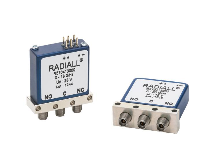
Device: SPDT Failsafe R570413000
How to calculate current at 70 °C with this relay?
In reference to specifications outlined in the technical data sheet:
• Coil resistance 275 Ohms at 25 °C ( R = 275, t = 25, t’ = 70 )
• Nominal current = 102 mA at 25 °C
• Nominal voltage = 28 volts
New coil resistance at 70 °C will be:
• R’ = 275 ( 1 + 0.0038 (70 – 25))
• R’ = 275 x 2.71
• R’ = 323 Ohms
According to the Ohm law ( U = R I ), at 70 °C:
• U = R x I
• I = 87 mA
1-18 | T ECHNICAL INFORMATION SIMPLIFICATION IS OUR INNOVATION Visit www.radiall.com for more information °C °F °C °F °C °F -80 -112 0 22 71 6 73 163 4 -70 -94 0 23 73 4 74 165 2 -60 -76 0 24 75 2 75 167 0 -50 -58 0 25 77 0 76 168 8 -45 -49 1 26 78 8 77 170 6 -40 -40 0 27 80 6 78 172 4 -35 -31 0 28 82 4 79 174 2 -30 -22 0 29 84 2 80 176 0 -25 -13 0 30 86 0 81 177 8 -20 -4 0 31 87 8 82 179 6 -19 -2 � 2 32 89�6 83 181� 4 -18 -0 4 33 91 4 84 183 2 -17 1 4 34 93 2 85 185 0 -16 3 2 35 95 0 86 186 6 -15 5 0 36 96 8 87 188 8 -14 6 8 37 98 6 88 190 4 -13 8 �6 38 100 � 4 89 192 � 2 -12 10 4 39 102 2 90 194 0 -11 12 2 40 104 0 91 195 8 -10 14 0 41 105 8 92 197 6 -9 15 8 42 107 6 93 199 4 -8 17�6 43 109� 4 94 201� 2 -7 19 4 44 111 2 95 203 0 -6 21 2 45 113 0 96 204 8 -5 23 0 46 144 8 97 206 6 -4 24 8 47 116 6 98 208 4 -3 26 6 48 118 4 99 210 2 -2 28 � 4 49 120 � 2 100 212 �0 -1 30 2 50 122 0 105 221 0 0 32 0 51 123 8 110 230 0 1 33 8 52 125 6 115 239 0 2 35 6 53 127 4 120 248 0 3 37� 4 54 129� 2 130 266 �0 4 39 2 55 131 0 140 284 0 5 41 0 56 132 8 150 302 0 6 42 8 57 134 6 160 320 0 7 44 6 58 136 4 170 338 0 8 46 4 59 138 2 180 356 0 9 48 � 2 60 140 �0 190 374 �0
°C °F °C °F °C °F 10 50 0 61 141 8 200 392 0 11 51 8 62 143 6 250 482 0 12 53 6 63 145 4 300 572 0 13 55 4 64 147 2 350 662 0 14 57 2 65 149 0 400 752 0 15 59 0 66 150 8 500 932 0 16 60 8 67 152 6 600 1112 0 17 62 6 68 154 4 700 1292 0 18 64 4 69 156 2 800 1472 0 19 66 2 70 158 0 900 1652 0 20 68 �0 71 159� 8 1000 1832 �0 21 69 8 72 161 6 - -
Introduction
COIL RESISTANCE VALUE VERSUS TEMPERATURE
The following graphs are examples of calculation for the same product R570413000 (SPDT SMA).
MAXIMUM PICK UP VOLTAGE VERSUS TEMPERATURE
CURRENT VALUE VERSUS VOLTAGE OVER TEMPERATURE RANGE
For customer support and more technical information contact a Radiall sales representative.
T ECHNICAL INFORMATION | 1-19 SIMPLIFICATION IS OUR INNOVATION Visit www.radiall.com for more information
CONVERSIONS (CONTINUED)
COIL RESISTANCE VALUE VERSUS TEMPERATURE Introduction
MAXIMUM PICK UP VOLTAGE VARIATION VERSUS TEMPERATURE
1-20 | T ECHNICAL INFORMATION SIMPLIFICATION IS OUR INNOVATION Visit www.radiall.com for more information
Introduction
USER HANDBOOK
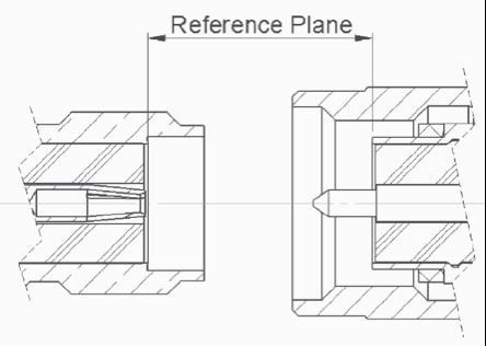
FOR CONNECTOR ASSEMBLY ON COAXIAL SWITCHES
When connecting RF coaxial connectors to Radiall switches precaution should be taken to avoid irreversible damage on the RF switches �
Use only connectors with the correct interface dimensions.
To ensure appropriate torque on the connector, and avoid damage on the contacts it is recommended to use a specific tool with calibrated torque� Apply the recommended torque as shown below:
SMA CONNECTORS
TNC CONNECTORS from 80 to 120 N cm 265 N cm
Connection of semi-rigid cable using the center contact of the cables as pin for connecting the female connector.
If the center contact is not in alignment with the female socket, the switch RF connector could be damaged.
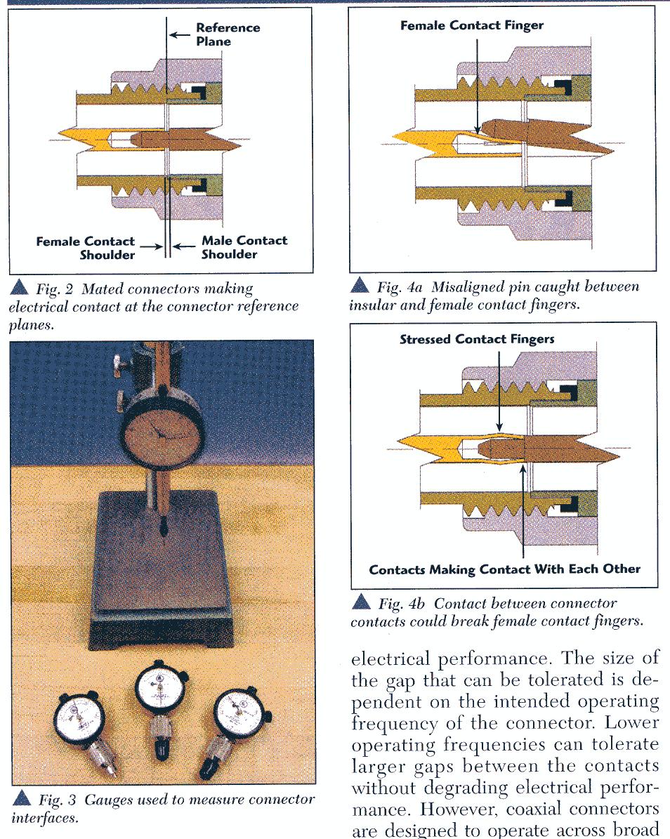
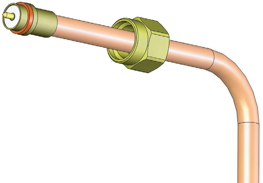
RF connectors with removable nut allow visual confirmation that the center contact is correctly positioned.
CONNECTOR
R125 052 500
R125 055 500
T ECHNICAL INFORMATION | 1-21 Visit www.radiall.com for more information
FEMALE MALE
FIG A: MISALIGNED PIN BETWEEN INSULATOR & FEMALE
FIG B: SEMI-RIGID CABLE WITH REMOVABLE NUT SMA CONTACT
Female contacts slots
Introduction APPLICATIONS
Instrumentation

Wireless communication

Military

Space

Automated test
Measurement equipments
Monitoring devices
Test network
Telecommunication
Tower mount amplifiers
BTS
Radio links
ECM equipments
Repeaters
Base stations
Point to point link
Military radios
Electronic warfare
Radar
Pay load: Various satellites Communication Observation
Ground segment
Test equipments
Earth stations
1-22 | T ECHNICAL INFORMATION SIMPLIFICATION IS OUR INNOVATION Visit www.radiall.com for more information
APPLICATIONS QUARTZ RAMSES & USB SERIES TITANIUM PLATINUM TVAC PRODUCTS SPACE COMPONENTS
N/A
N/A
N/A
Pay load: N/A
SIMPLIFICATION IS OUR INNOVATION Visit www.radiall.com for more information SECTION 2 SPDT
Section 2 Table of Contents
QUARTZ SERIES
SMT Power Micro-SPDT with 26 � 5 GHz capabilities: R516 Series ����������������������� 2-2 to 2-8 Applications
RAMSES SERIES
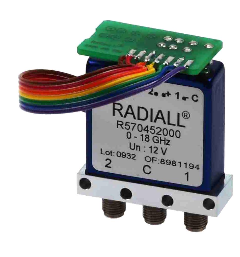
SPDT up to 50 GHz: R570 Series (miniature models) ����������������������� 2-10
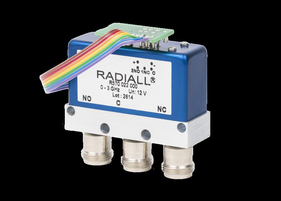
SPDT up to 18 GHz: R570 Series (N, BNC and TNC models) 2-16 to 2-19
ELECTRICAL SCHEMATICS
Coaxial SPDT: R570 Series
PLATINUM SERIES
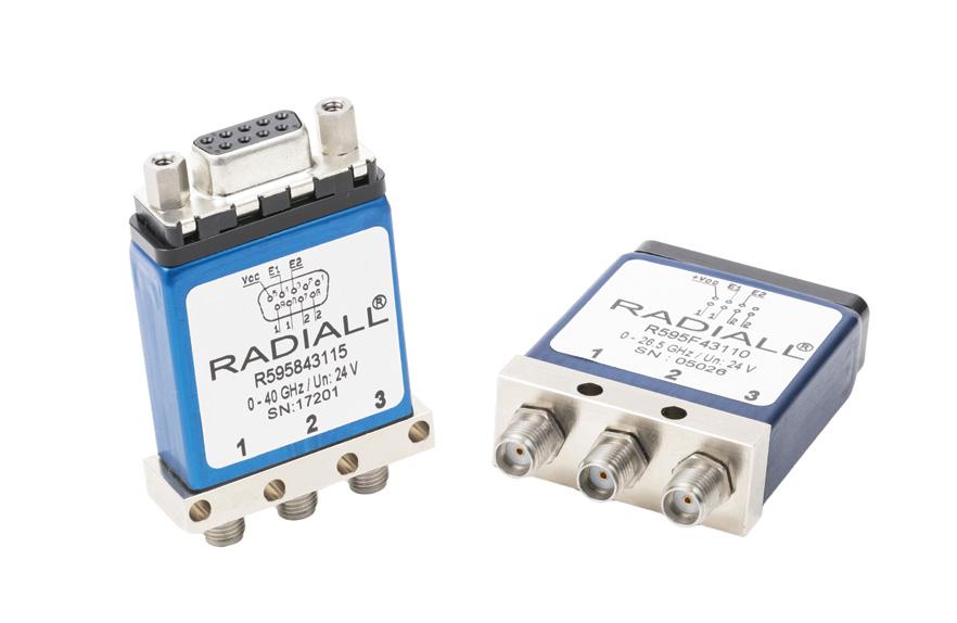
High Performance SPDT up to 40 GHz: R595 Series
OPTIONAL FEATURES
2-24 to 2-29
Optional Features ����������������������������������������������������������
Notes
Example of P/N: R570F12010 is a SPDT SMA 26.5 GHz, failsafe, 12 Vdc, without TTL, with positive common, solder pins. 1. For part number creation and available options, see detailed part number selection for each series.
SPDT | 2-1 SIMPLIFICATION IS OUR INNOVATION Visit www.radiall.com for more information
2-9
to 2-15
DIGITAL POSITION R: 1-3 4: RF CONNECTORS 5: TYPE 6: VOLTAGE 7: TTL OPT./ MODEL 8: OPTIONS 9: TERMINALS 10: DOCUMENT- ATION Series ConfigurationDC8 GHz DC18 GHz DC26.5 GHz SMA 3 GHz SMA 6 GHz SMA 18 GHz SMA 20 GHz SMA 26 � 5 GHz SMA 2 9 40 GHz 2 � 4mm 50 GHz QMA 6 GHz DIN 1.6/5.6, 2.5 GHzPc board mount 3 GHz N 3 GHz N 12 � 4 GHz BNC 3 GHz TNC 3 GHz TNC 12 � 4 GHz TNC 18 GHz Failsafe Latching 6 V 12 V 15 V 24 V 28 V Without With SPDT non-terminated - Without option Positive common
diodes
diodes and positive common
with TTL driver -
PLATINUM SPDT R595 - - - - 3 - 4 F 8 - - - - - - - - - - - - 3/4/5/6 - - 7 3 - - - 1 - 1 1 - - 2 - - - 0 5 - C R RAMSES SPDT R570 - - - 3 - 4 - F 8 J E 9 H A - - - - - - 1/2 3/4/5/6 - 2 - - 3 0 1 - - 0 1 3 4 - - - - 0 - - -R570 - - - - - - - - - - - - - - 0 1 2 5 6 D 1/2 3/4/5/6 - 2 - - 3 0 1 - - 0 1 3 4 - - - - 0 5 - -Quartz SPDT R516 3 4 7 - - - - - - - - - - - - - - - - - 1/9 3 1 2 - 3 - - - - 1 - - - - - 0 0 T - - - - -
Supression
Suppression
Compatible
Not soldered Soldered on a connectorized test fixture Solder pins D-Sub connector Certificate of conformity Calibration certificate Calibration certificate + RF curves
SPDT PART NUMBER SELECTION GUIDE [1]
2-20 to 2-23
��������������������������������������������������������
2-30
Quartz Series
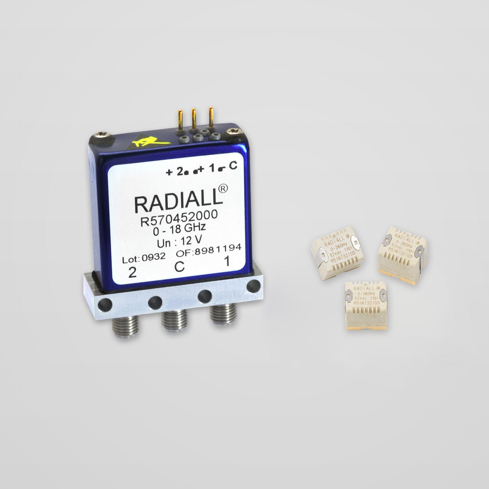
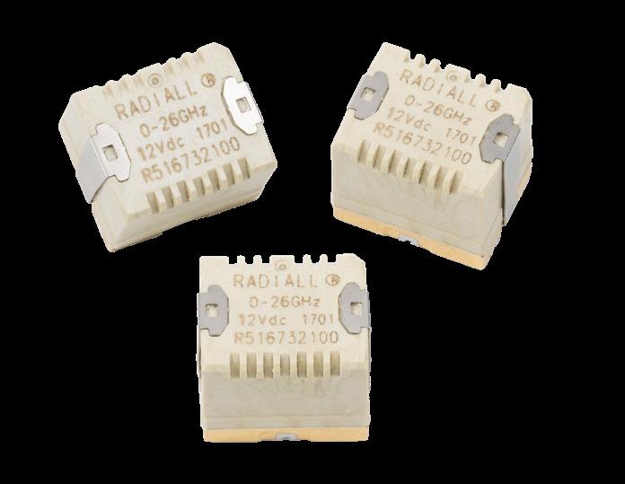
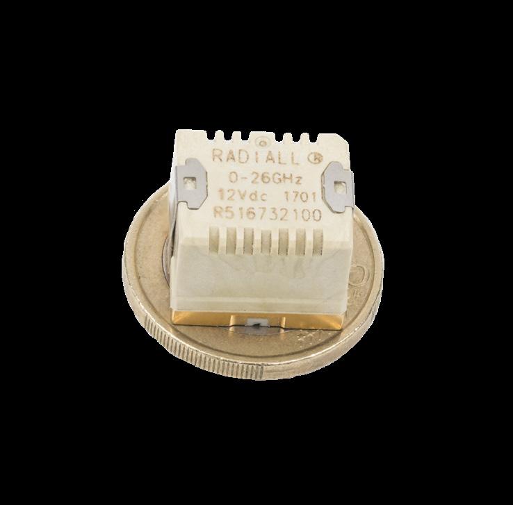
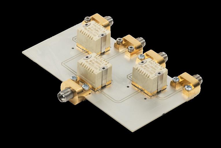
SMT POWER MICRO SPDT WITH 26.5 GHz CAPABILITIES SURFACE MOUNT TECHNOLOGY
An innovative and original "micro-mechanical" design of the R516 SMT micro-relay offers excellent RF performance, reliability, and repeatability. The miniature size and low installation cost make these coaxial switches an ideal solution
Very low return loss and insertion loss allow this relay to be used in power applications, as well as in typical SMT relay applications such as RF attenuators, RF matrices, spectrum analysers, and telecommunications.
Failsafe models are offered in two RF configurations (direct and inverted). The association of these two products on the same PC board enables the product to perform the bypass function. (For bypass mounting, further information is available on page 2-7 )
Example of P/N: R516713100 is a SPDT SMT 26.5 GHz, 24 Vdc, failsafe, not soldered.
ACTUAL SIZE

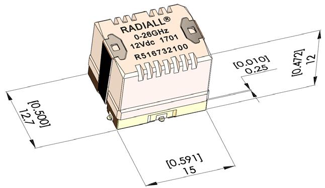
TYPICAL OUTLINE DRAWING
All dimensions are in millimeters [inches].
R516 10
PART NUMBER SELECTION
SERIES PREFIX
FREQUENCY RANGE
3: DC – 8 GHz
4: DC – 18 GHz
7: DC – 26.5 GHz
TYPE
1: Failsafe
3: Latching, 2 coils
9: Failsafe, inverted RF path [1]
ACTUATOR TERMINALS
0: Not soldered
T: Soldered on a connectorized test fixture [2]
ACTUATOR VOLTAGE
1: 6 Vdc [3]
2: 12 Vdc
3: 24 Vdc
Notes:
1. Can be combined with a failsafe model, so as to achieve the “BYPASS” function (see application details on page 2-6).
2. See details about test fixture dimensions on page 2-4. 3. Only available with type 3.
2-2 | SPDT SIMPLIFICATION IS OUR INNOVATION Visit www.radiall.com for more information
QUARTZ GENERAL SPECIFICATIONS
OPERATING MODE
FAILSAFE (TYPES 1 & 9)
LATCHING (TYPE 3) Nominal operating voltage (across
RF and command ports
Gold-plated access, infrared reflow, forced air oven or hand soldering (Compatible with “lead free” soldering processes)
Switching time at nominal voltage - Making contacts - Breaking contacts Max 5 ms (typical 2 ms), including contact bounce time 3 ms Life
- Cold switching (max 120 cycles/min) - Hot switching (max 20 cycles/min) 2 million cycles
Environmental protection Lead free construction - Waterproof (acc To IEC 60529 / IP64) Mass
(with no icing nor condensation)
Sine vibration (MIL STD 202, Method 204D)
Shocks (According to MIL STD 202, Method 213B, Cond. C)
PIN IDENTIFICATION (TOP VIEW)
FAILSAFE MODEL (TYPE 1)
VOLTAGE RF CONTINUITY
De-energized C <--> 1(NC)
Energized C <--> 2(NO)
Condition D: 10-2,000 Hz, 20 g
Operating
Condition G: 10-2,000 Hz, 30 g Non-operating
g / 6 ms, 1/2 sine Operating
INVERTED FAILSAFE MODEL FOR BYPASS APPLICATION (TYPE 9)
VOLTAGE RF CONTINUITY
De-energized C <--> 1(NC)
Energized C <--> 2(NO)
Notes
1. Failsafe models may be used down to –40 °C, for this application please follow requirements of AN-R516-51. Contact Radiall for a copy of this application note.
LATCHING MODEL (TYPE 3)
SPDT | 2-3 SIMPLIFICATION IS OUR INNOVATION Visit www.radiall.com for more information
Quartz Series
temperature range) Vdc 12 (10 5 to 13) 24 (21 5 to 30) 6 (5 1 to 6 6) 12 (10 2 to 13) 24 (20 5 to 30) Coil resistance at 23 °C (+/- 10%) Ω 195 710 55 205 865 Operating current at 23 °C mA 61 32 108 58 32
3 million
500�000
cycles (5 million cycles typical at low level)
cycles Insulation
300
500
> 100
Dielectric test voltage
Vrms Insulation resistance at
Vdc
MOhms
temperature range
°C -25 to +70 [1] -40 to +85 Storage temperature range °C -55 to +85
8 g Operating
100
VOLTAGE RF CONTINUITY -1 +1 C <--> 1 -2 +2 C <--> 2
QUARTZ PERFORMANCE (S PARAMETERS AVAILABLE ON REQUEST)
MEASUREMENT METHOD
RELAY SOLDERED ON TEST FIXTURE [1]
CALIBRATION BOARD
Inputs/Outputs of the calibration board and test fixture are equipped with coaxial type receptacle connectors. The length of the RF tracks is the same on the calibration board and the test fixture circuits. The insertion loss of the relay itself is calculated by subtracting the insertion loss of the “calibration board” to the insertion loss of the “relay soldered on the test fixture.”
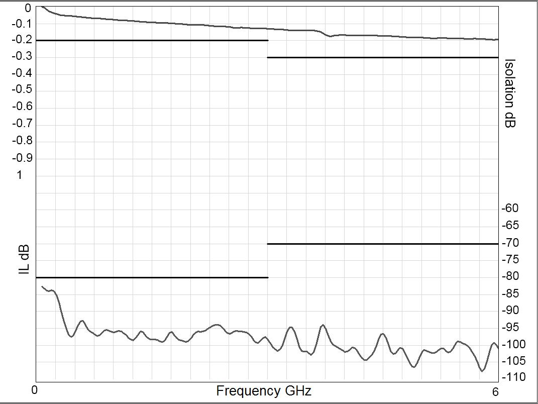
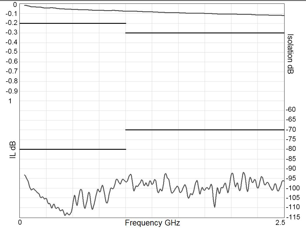
TYPICAL RF PERFORMANCE
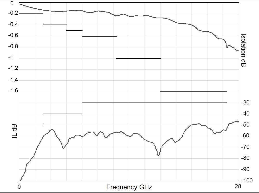
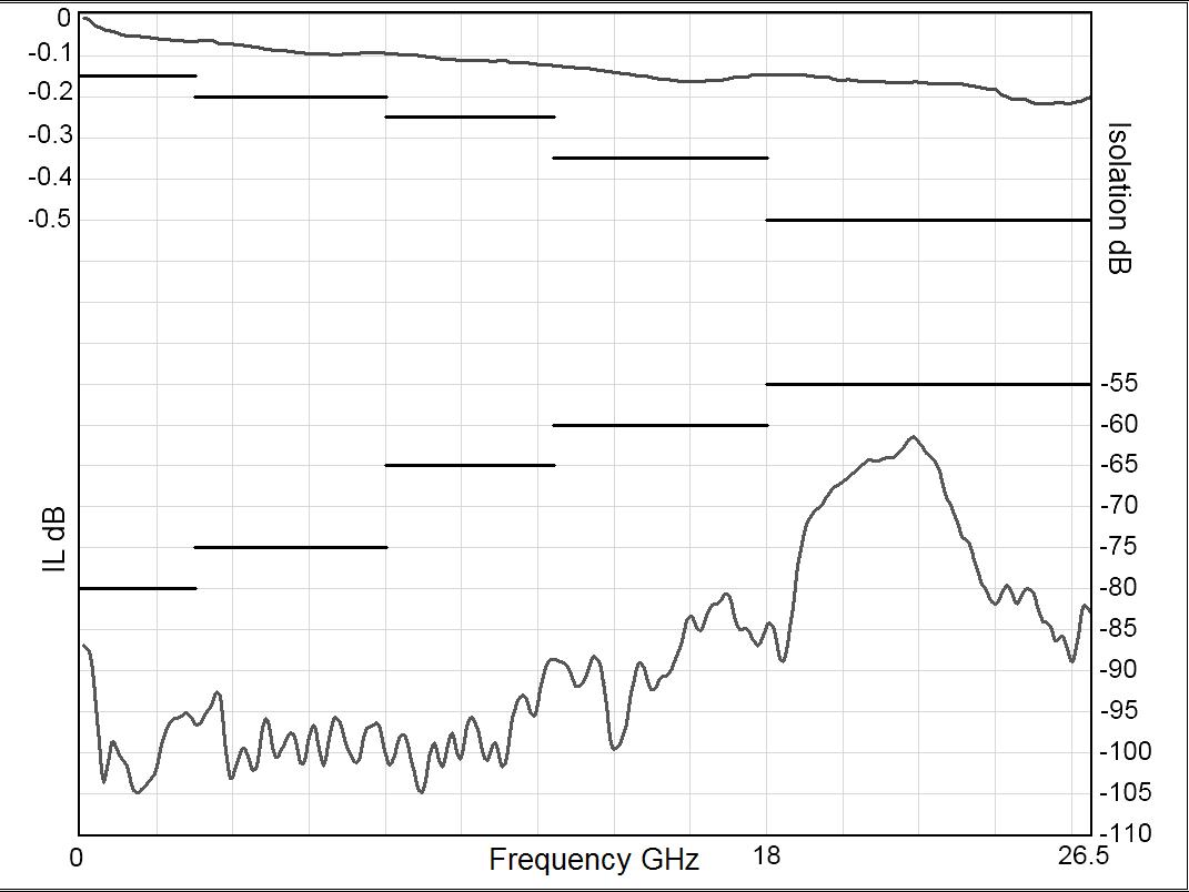
INSERTION LOSS & ISOLATION
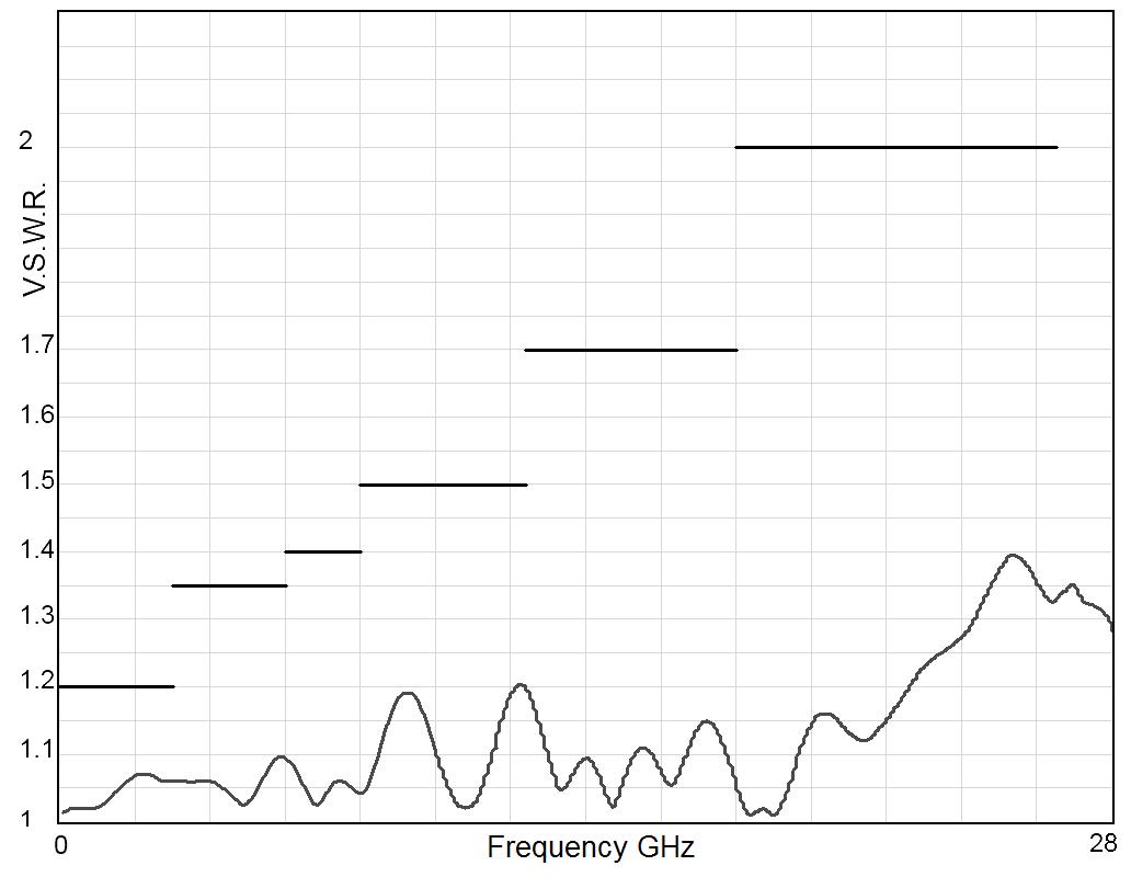
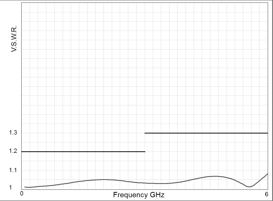
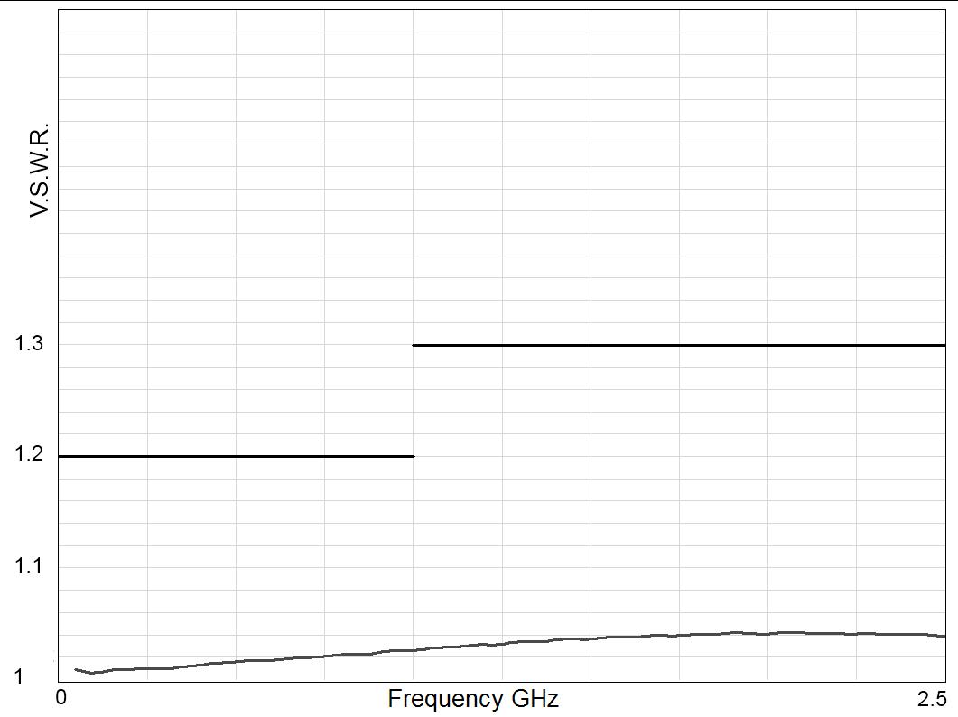
V.S.W.R
Notes 1. Relay soldered on Test Fixture is available. To order, please use the suffix "T" (part number R516 - - - - - T), as explained in page 2-2. All dimensions are in millimeters [inches].
2-4 | SPDT SIMPLIFICATION IS OUR INNOVATION Visit www.radiall.com for more information
Quartz Series
FREQUENCY RANGE GH z V.S.W.R. (MAX) INSERTION LOSS (MAX) dB ISOLATION (MIN) dB THIRD ORDER INTER MODULATION IMPEDANCE Ω SWITCH ALONE DC – 8 DC – 18 DC – 26.5 DC – 3 1 20 0 20 50 -110 dBc typical at 1730 MHz (2 carriers 20 W) 50 3 – 6 1� 35 0� 40 40 6 – 8 1 40 0 50 40 8 – 12.4 1 50 0 60 40 12.4 – 18 1 70 1 00 40 18 – 26.5 2 00 1 60 40
Frequency (GHz) Frequency (GHz)
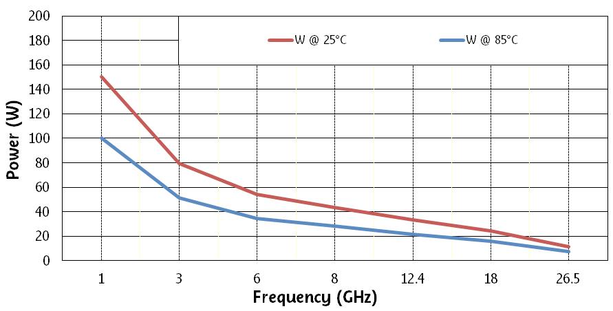
RF POWER RATING FOR COLD SWITCHING USE
(IMPEDANCE 50 OHMS, V.S.W.R. < 1.25)
Power level depends on environmental conditions:
• R516 series have been designed to be used without a cooling fan even for high power applications. However, the power capability may be still improved by using the appropriate cooling fan�
• For failsafe models used with coil permanently supplied (N/O position), the same power level as latching models may be applied�
RELAY PACKAGING
ACCORDING TO IEC 286-3 STANDARD
Materials:
• Reel: polyester
• Carrier tape: PVC
• Cover tape: polyester
SPDT | 2-5 SIMPLIFICATION IS OUR INNOVATION Visit www.radiall.com for more information
Quartz Series
ASPIRATION AREA
BYPASS APPLICATION
FAILSAFE MICRO-RELAY TYPICAL IMPLANTATION
SPDT relays (Single Pole Double Throw) can be used to achieve a bypass switch function. For SMT applications, R516 series, relays are available in two failsafe versions, standard and inverted, to provide symmetric RF ports implantation possibility. The “side by side” implementation of these two versions on a PCB effectively produces the bypass function. The package size is reduced and interconnecting tracks are shortened Required in order to protect the receiver for transmit/receive applications RF performance of bypass switch assemblies depend on the distance between the two RF SMT relays �
Notes
All dimensions are in millimeters [inches].
2-6 | SPDT SIMPLIFICATION IS OUR INNOVATION Visit www.radiall.com for more information
Quartz Series
VIDEO SHADOW OF THE RELAY
PC BOARD MOUNTING
Board layout
DXF or Gerber format file available upon request.
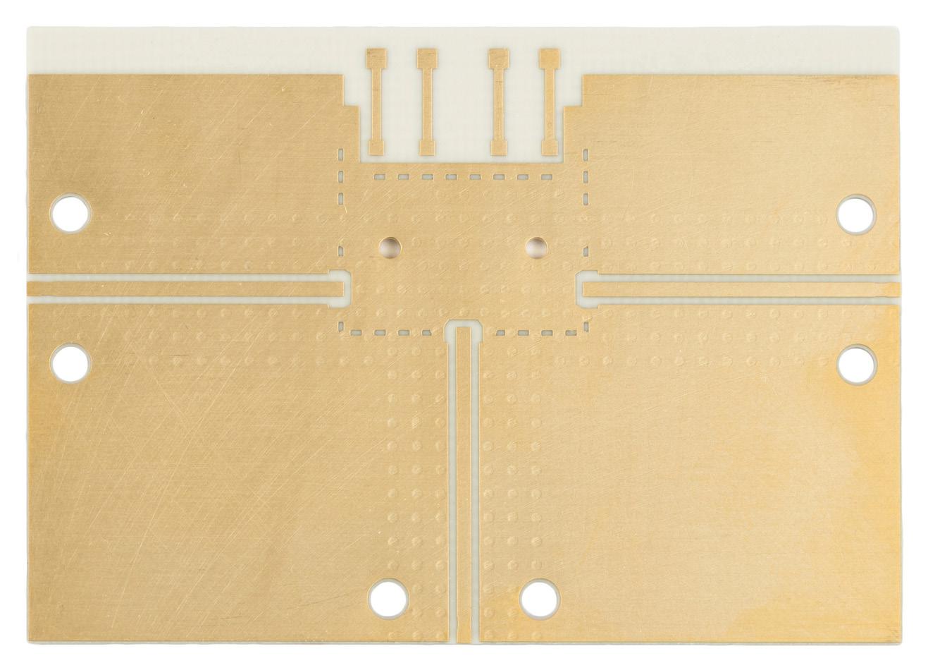
SUBSTRATE TYPES
Recommended substrates are ROGERS RO4003. Thickness 0.508 mm Cu double side 17.5 μm.
Recommended total thickness of RF tracks (copper over thickness + plating): 40 μm. Other substrates may be used
Notes
Please contact your local sales representative for additional information.
SPDT | 2-7 SIMPLIFICATION IS OUR INNOVATION Visit www.radiall.com for more information
Quartz Series
RECOMMENDED SOLDERING PROCEDURE
A - Soldering procedure using automatic pick and place equipment
1 - Solder paste: R516 series are “Lead Free”, and Lead Free Sn-Ag3� 5-Cu0�7 solder cream may be used as well as standard Sn63–Pb35–Ag2. Radiall recommends using a "no clean - low residue" solder cream (5% solid residue of flux quantity) that will permit the elimination of the cleaning operation step after soldering�
Note: Due to the gold plating of the switch PCB interface, it is important to use a paste made with silver. This will help in avoiding formation of intermetallics as part of the solder joint.
2 - Solder paste deposition: Solder cream may be applied on the board with screen printing or dispenser technologies. For either method, the solder paste must be coated to appropriate thickness and shapes to achieve good solder wetting Please optically verify that the edges of the zone are clean and without contaminates, and that the PCB zoned areas have not oxydated� The design of the mounting pads and the stenciling area are available upon request, for a thickness of the silk-screen printing of 0.15 mm (0.006 ‘’.)
3 - Placement of the component: For small lightweight components such as chip components, a self-alignment effect can be expected if small placement errors exist. However, this effect is not as expected for relays components and they require a accurate positioning on their soldering pads, typically +/- 0.1 mm (+/-0.004’’.)
Place the relay onto the PCB with automatic pick and place equipment Various types of suction can be used Radiall does not recommend using adhesive agents on the component or on the PCB
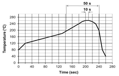
4 - Soldering: infrared process: Please follow the Radiall recommended max temperature profile for infrared reflow or forced air convection:
5 - Cleaning procedure: On miniature relays, high frequency cleaning may cause the contacts to stick� If cleaning is needed, please avoid ultrasonic cleaning and use alcohol based cleaning solutions
In-line cleaning process, spraying, immersion, especially under temperature, may cause a risk of degradation of internal contacts. For such cleaning process please contact us. !
6 - Quality check: Verify by visual inspection that the component is centered on the mounting pads� Solder joints: verify by visual inspection that the formation of meniscus on the pads are proper
B – Soldering procedure by manual operation
Manual soldering is not recommended for high frequencies, as it generates resonance and lower RF characteristics due to gaps between PC board and relay grounds. !
1 - Solder paste and flux deposition: Refer to procedure A – 1. Deposit a thin layer of flux on solder pad area. Allow the flux to evaporate a few seconds before applying the solder paste, it will prevent dilution of the paste.
2 - Solder paste deposition: Radiall recommends depositing a small amount of solder paste on solder pad area by syringe, according to the manual soldering pattern (available upon request ) Be careful not to apply solder paste outside of the zone area
3 - Placement of the component: During manipulation, avoid contaminating gold surfaces by contact with fingers. Place the component on the mounting zone by pressing on the top of the relay lid
4 - Hand soldering: Iron wattage 30 to 60 W To keep better RF characteristics, apply pressure on the relay lid during all the soldering stage, so as to reduce the air gap between the PC board and the relay. If possible, fix the ground plane of the relay on the board with two M1 2 screws before the soldering stage On each side of the central RF access, the RF body edge must be soldered to the ground of the PC board� To improve RF characteristics and avoid soldering the RF body to the ground, a conductive gasket may be used (please contact us for detailed application note )
5 - Cleaning procedure: Refer to procedure A – 5.
6 - Quality check: Verify by visual inspection that component is centered on the mounting pads � Solder joints: verify by visual inspection that there is no solder excess on the RF pads
2-8 | SPDT SIMPLIFICATION IS OUR INNOVATION Visit www.radiall.com for more information
Quartz Series
Higher temperature (>260 °C) and longer process duration would permanently damage the switches. !
Quartz Series APPLICATIONS
PC BOARD MOUNTING
The SMT Series offers a large range of products which can be used in many applications such as:
• Tower mount amplifiers
• Instrumentation
• Military radios
• ECM equipment
• Remote Radio Unit (RRU)
• Radio-Links
• Repeaters
These products offer the same RF Board and soldering process as all RF components but with a reduced weight and size. They are designed to meet all market specifications.
INSTRUMENTATION
ECM EQUIPMENT
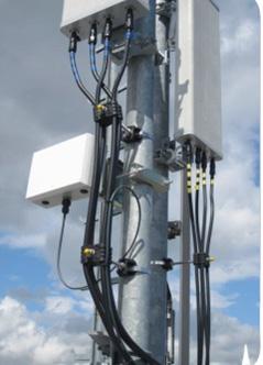
TOWER MOUNT AMPLIFIER
REPEATERS RADIO-LINKS
REMOTE RADIO UNITS (RRU)

SPDT | 2-9 SIMPLIFICATION IS OUR INNOVATION Visit www.radiall.com for more information
MILITARY RADIO
RAMSES Series
SPDT UP TO 50 GHz
PC BOARD - SMA - SMA 2.9 - 2.4 MM - QMA - DIN 1.6/5.6

PART NUMBER SELECTION
SERIES PREFIX
FREQUENCY RANGE
3: SMA up to 3 GHz
E: QMA up to 6 GHz [5]
4: SMA up to 18 GHz
F: SMA up to 26 � 5 GHz
8: SMA 2 9 up to 40 GHz [6]
J: 2 4 mm up to 50 GHz
9: DIN 1.6/5.6 up to 2.5 GHz
A: PC board mount up to 3 GHz [4]
TYPE
1: Failsafe
2: Failsafe + I C
3: Latching
4: Latching + I C
5: Latching + S C O [1]
6: Latching + S C O + I C [1]
ACTUATOR VOLTAGE
2: 12 Vdc
3: 28 Vdc
Radiall’s RAMSES SPDT switches offer excellent reliability, high performance and operating frequencies from DC to 50 GHz. Radiall's RAMSES concept (which provides for a life span of 10 million cycles) offers a variety of options to meet customer needs
These switches are dedicated to all market applications including: military, instrumentation and telecommunications �
Example of P/N: R570413100 is a SPDT SMA 18 GHz, failsafe, 28 Vdc, with TTL driver, without option, solder pins.
R570
ACTUATOR TERMINALS
0: Solder pins
OPTIONS
0: Without option
1: Positive common [2 & 3]
3: With suppression diodes [1]
4: With suppression diodes and positive common [1, 2 & 3]
TTL OPTION
0: Without TTL driver
1: With TTL driver [1 & 2]
Notes:
I.C.: Indicator contact - S.C.O.: Self Cut-Off.
1. Suppression diodes are already included in Self Cut-Off and TTL option.
2. Polarity is not relevant to application for switches with TTL driver.
3. Positive common shall be specified only with type 3, 4, 5, and 6 because failsafe switches can be used with both polarities.
4. Available only upon request.

5. The QLF tradermark (Quick Lock Formula®) standard applies to QMA and QN series and guaranties the full intermateability between suppliers using this tradermark. Using QLF certified connectors also guarantees the specified level of RF performance.
6. Connector SMA 2.9 is equivalent to "K connector ®", registered trademark of Anritsu.
2-10 | SPDT SIMPLIFICATION IS OUR INNOVATION Visit www.radiall.com for more information
RAMSES Series
GENERAL SPECIFICATIONS
OPERATING MODE
Average power See Power Rating Chart page 1-13
rating
SMA - SMA 2 9 - QMA
- PC Board
Operating temperature range DIN 1.6/5.6 - 2.4 mm
Storage temperature range
SMA - SMA 2 9 - QMAPC Board
DIN 1.6/5.6 - 2.4 mm
SMA - SMA 2 9 - QMAPC Board
Vibration (MIL STD 202, Method 204D, cond.D)
Shock (MIL STD 202, Method 213B, cond.C)
RF PERFORMANCE
Notes
See page 2-12 and 2-13 for typical RF performance.
°C to +85 °C
g / 6 ms, ½ sine Operating
SPDT | 2-11 SIMPLIFICATION IS OUR INNOVATION Visit www.radiall.com for more information
FAILSAFE LATCHING Nominal
temperature range) Vdc 12 (10 � 2 to 13) 28 (24 to 30) 12 (10� 2 to 13) 28 (24 to 30) Coil resistance at 23 °C (+/-10%) Ω 47 5 275 58 350 Operating current at 23 °C mA 250 102 210 80
High level 2 � 2 to 5 � 5 Volts 800 µA max 5 � 5 Volts Low level 0 to 0 8 Volts 20 µA max 0 8 Volts
operating voltage (across
TTL Input
100
Indicator
1 W / 30 V /
mA Switching time ms 10 Life
10
5 million
2 million cycles Connectors SMA - SMA 2.9 - QMA - DIN 1.6/5.6
PC Board -
mm
million cycles DIN 1.6/5.6
cycles 2 4 mm
-
2.4
-25
°C to +70 °C
-40
°C to +85 °C
-40
-55
°C to +85 °C
10-2,000
Operating
100
Hz, 20 g
CONNECTORS FREQUENCY RANGE GH z V.S.W.R. (MAX) INSERTION LOSS (MAX) d B ISOLATION (MIN) dB IMPEDANCE Ω DIN 1.6/5.6 DC - 2.5 DC - 1 1 20 0 20 80 75 1 - 2 5 1 30 0 30 70 QMA DC - 6 DC - 3 1 20 0 20 80 50 3 - 6 1� 30 0� 30 70 SMA DC - 3 DC - 18 DC - 26.5 DC - 3 1 10 0 15 80 3 - 8 1� 20 0� 20 75 8 - 12 4 1 20 0 25 65 12 4 - 18 1 40 0 35 60 18 - 26 5 1 50 0 50 55 SMA 2 9 DC - 40 DC - 6 1 30 0 30 70 6 - 12 4 1 40 0 40 60 12 4 - 18 1 50 0 50 60 18 - 26 5 1 70 0 70 55 26 5 - 40 1 90 0 80 50 PC Board DC - 3 DC - 3 1 20 0 20 80 2 4 mm DC - 50 DC - 6 1 30 0 30 70 6 - 12 � 4 1� 40 0� 40 60 12 4 - 18 1 50 0 50 60 18 - 26 5 1 70 0 70 55 26 5 - 40 1 90 0 80 50 40 - 50 1 90 1 10 50
RAMSES Series
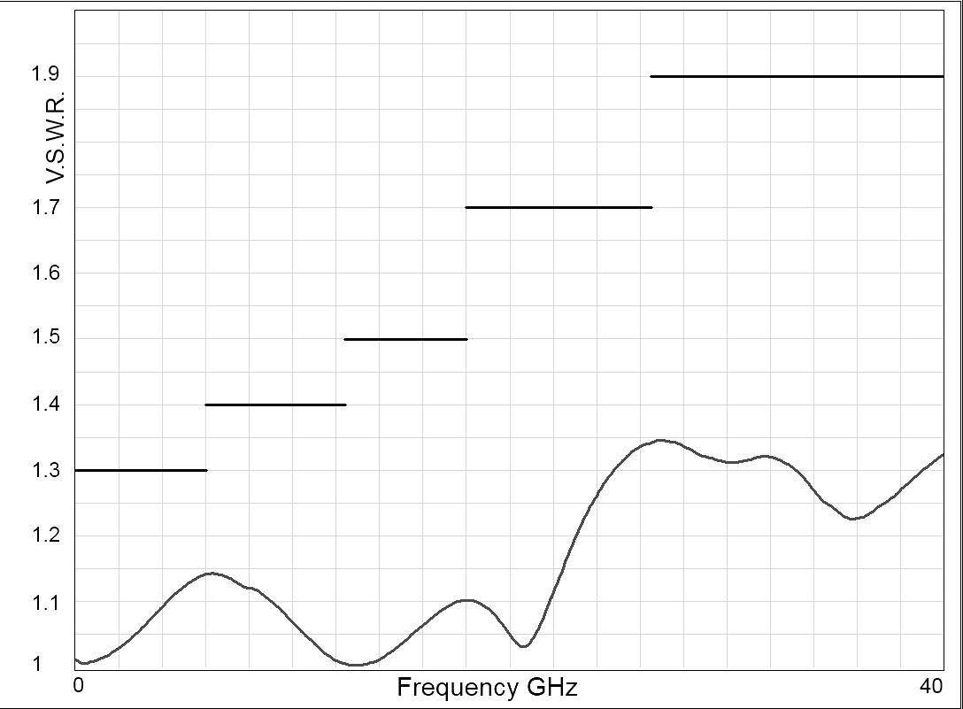
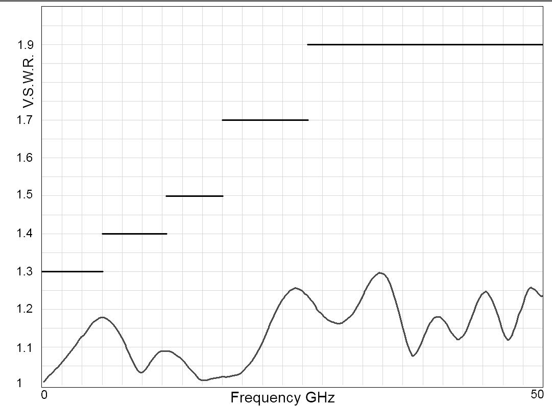
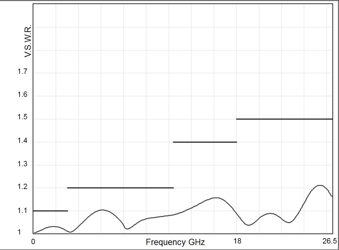
R570 TYPICAL RF PERFORMANCE
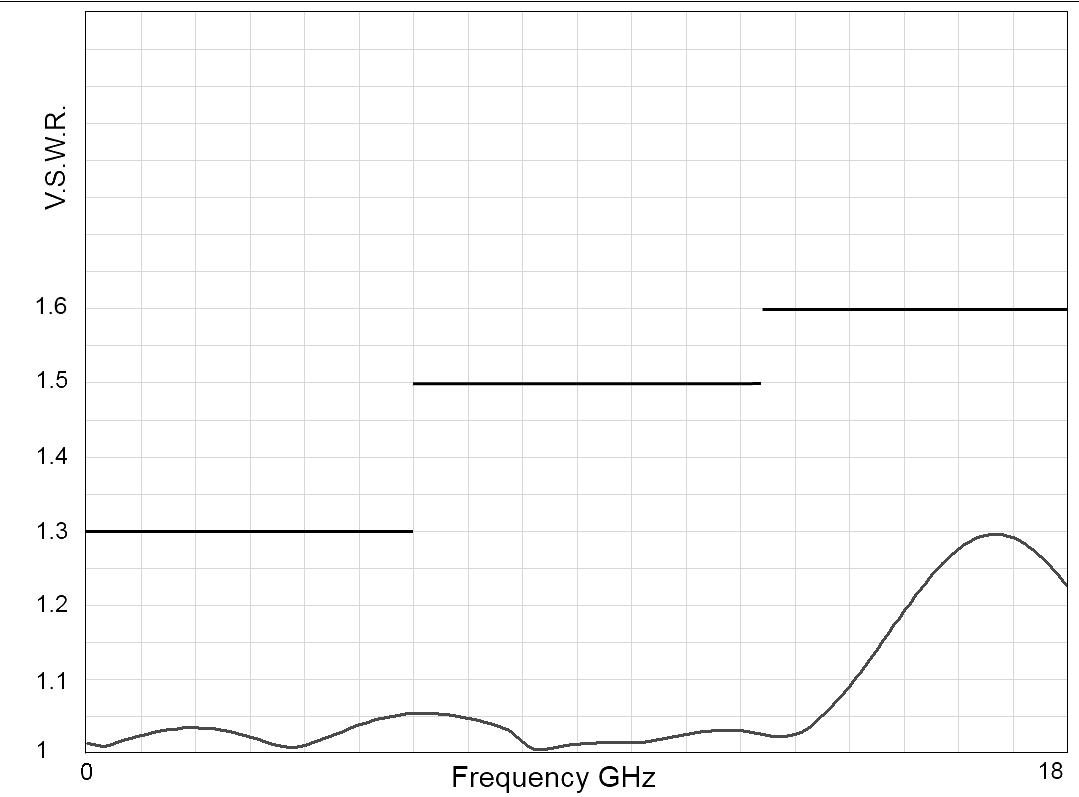
Example: SPDT SMA 2.9 up to 40 GHz
INSERTION LOSS & ISOLATION
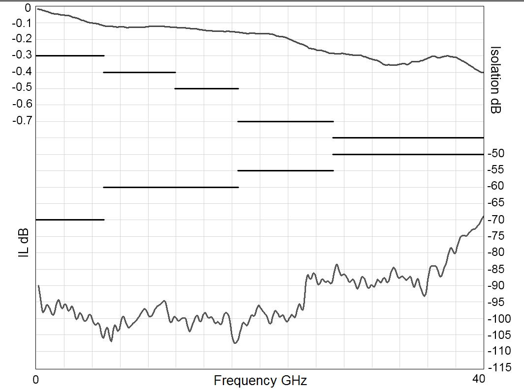
Frequency (GHz)
Example: SPDT 2.4 mm up to 50 GHz
INSERTION LOSS & ISOLATION
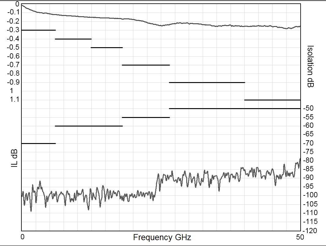
Frequency (GHz)
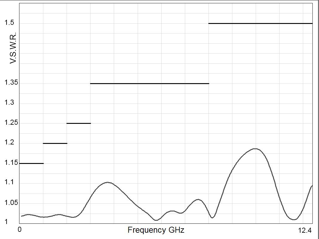
Example: SPDT SMA up to 26.5 GHz
INSERTION LOSS & ISOLATION
Frequency (GHz)
V.S.W.R
Frequency (GHz)
V.S.W.R
Frequency (GHz)
V.S.W.R
Frequency (GHz)
2-12 | SPDT SIMPLIFICATION IS OUR INNOVATION Visit www.radiall.com for more information
R570 TYPICAL RF PERFORMANCE (CONTINUED)
INSERTION LOSS & ISOLATION
Example: SPDT QMA up to 6 GHz Frequency
Example: SPDT DIN 1.6/5.6 up to 2.5 GHz
INSERTION LOSS & ISOLATION
V.S.W.R
V.S.W.R
SPDT | 2-13 SIMPLIFICATION IS OUR INNOVATION Visit www.radiall.com for more information
RAMSES Series
Frequency (GHz) Frequency (GHz) Frequency (GHz)
(GHz)
TYPICAL OUTLINE DRAWING
CONNECTORS
Notes
See page 2-23 for pin identification. All dimensions are in millimeters [inches].
2-14 | SPDT SIMPLIFICATION IS OUR INNOVATION Visit www.radiall.com for more information
A MAX
SMA 7
SMA 2
6
QMA 10 8
DIN 1.6/5.6 11 5 [0 433] PC Board 4 5 [0 157]
(MM [INCHES])
7 [0 303]
�9 and 2 � 4 mm
�7 [0 � 264]
[0 394]
RAMSES Series
ACCESSORIES
A printed circuit board interface connector (ordered separately) has been designed for easy mounting on terminals For SPDT model R570 series = Radiall part number: R599 910 000.
Notes
All dimensions are in millimeters [inches]. The PCB accessory pin number assignment is independant from the pin identification table of the switch.
SPDT | 2-15 SIMPLIFICATION IS OUR INNOVATION Visit www.radiall.com for more information
RAMSES Series
RAMSES Series
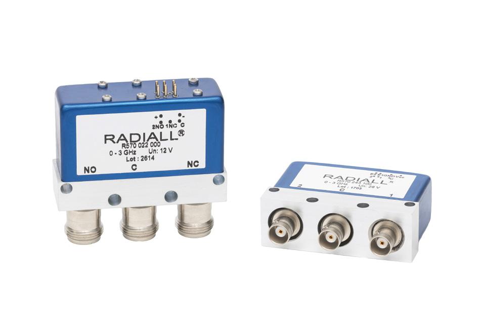
SPDT UP TO 18 GHz
N - TNC - BNC
PART NUMBER SELECTION
SERIES PREFIX
FREQUENCY RANGE
0: N up to 3 GHz
1: N up to 12 4 GHz
2: BNC up to 3 GHz
5: TNC up to 3 GHz
6: TNC up to 12 � 4 GHz
D: TNC up to 18 GHz
TYPE
1: Failsafe
2: Failsafe + I C
3: Latching
4: Latching + I �C �
5: Latching + S �C �O� [1]
6: Latching + S C O + I C [1]
ACTUATOR VOLTAGE
2: 12 Vdc
3: 28 Vdc
Radiall’s RAMSES SPDT N, BNC and TNC switches are designed for high performance in RF & Microwave systems up to 18 GHz.
Radiall's RAMSES concept (modular concept) offers a full range of configurations. They are commonly used for applications where high power handling capability is required
These switches are dedicated to all market applications including: defense, instrumentation and telecommunications.
Example of P/N: R570113035 is a SPDT N 12.4 GHz, failsafe, 28 Vdc, with supression diodes, without option, D-Sub connector.
R570
ACTUATOR TERMINALS
0: Solder pins
5: D-Sub connector
OPTIONS
0: Without option
1: Positive common [2 & 3]
3: With suppression diodes [1]
4: With suppression diodes and positive common [1, 2 & 3]
TTL OPTION
0: Without TTL driver
1: With TTL driver [1 & 2]
Notes
I.C.: Indicator contact - S.C.O.: Self Cut-Off.
1. Suppression diodes are already included in Self Cut-OFF and TTL option.
2. Polarity is not relevant to application for switches with TTL driver.
3. Positive common shall be specified only with type 3, 4, 5 and 6 because failsafe switches can be used with both polarities.
2-16 | SPDT SIMPLIFICATION IS OUR INNOVATION Visit www.radiall.com for more information
GENERAL SPECIFICATION
time
Connectors N - TNC - BNC
Actuator terminals Solders pins or 9 pin D-Sub connector Operating
Vibration (MIL STD 202, Method 204D, cond.D)
(MIL STD 202, Method 213B, cond.C)
RF PERFORMANCE
Notes See page 2-18 for typical RF performance.
SPDT | 2-17 SIMPLIFICATION IS OUR INNOVATION Visit www.radiall.com for more information
FAILSAFE LATCHING Nominal operating voltage (across temperature range) Vdc 12 28 12 28 (10 � 2 to 13) (24 to 30) (10� 2 to 13) (24 to 30) Coil resistance at 23 °C (+/-10%) Ω 38 200 38 225 Operating current at 23 °C mA 320 140 320 125
TTL input High level 2 2 to 5 5 Volts / 800 µA max 5 5 Volts Low level 0 to 0 8 Volts
20 µA max 0 8 Volts
OPERATING MODE
Average power See Power Rating Chart page 1-13
/
Indicator rating ms 1 W/30 V/100 mA
Switching
ms 10 Life 2 5 million cycles
-40 °C to +85 °C Storage temperature range -55 °C to +85 °C
10 - 2,000 Hz, 20 g Operating
100
temperature range
Shock
g, 6 ms, ½ sine Non-operating
RANGE GH z V.S.W.R. (MAX) INSERTION LOSS (MAX) d B ISOLATION (MIN) dB IMPEDANCE Ω N/TNC DC - 3 DC - 12.4 DC - 1 1 15 0 15 85 50 1-2 1 20 0 20 80 2 - 3 1 25 0 25 75 3 - 8 1 35 0 35 70 8 - 12 4 1 50 0 50 60 TNC 18 DC - 18 DC - 6 1 30 0 30 70 6 - 12 4 1 50 0 50 60 12 4 - 18 1 60 0 70 60 BNC DC - 3 DC - 1 1 15 0 15 85 1 - 2 1� 20 0� 20 80 2-3 1 25 0 25 75
CONNECTORS FREQUENCY
RAMSES Series
RAMSES Series
R570 TYPICAL RF PERFORMANCE
Example: SPDT N and TNC up to 12.4 GHz
INSERTION LOSS & ISOLATION
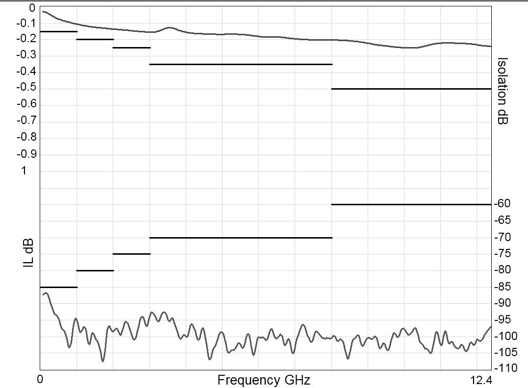
Frequency (GHz)
Example: SPDT TNC up to 18 GHz
INSERTION LOSS & ISOLATION
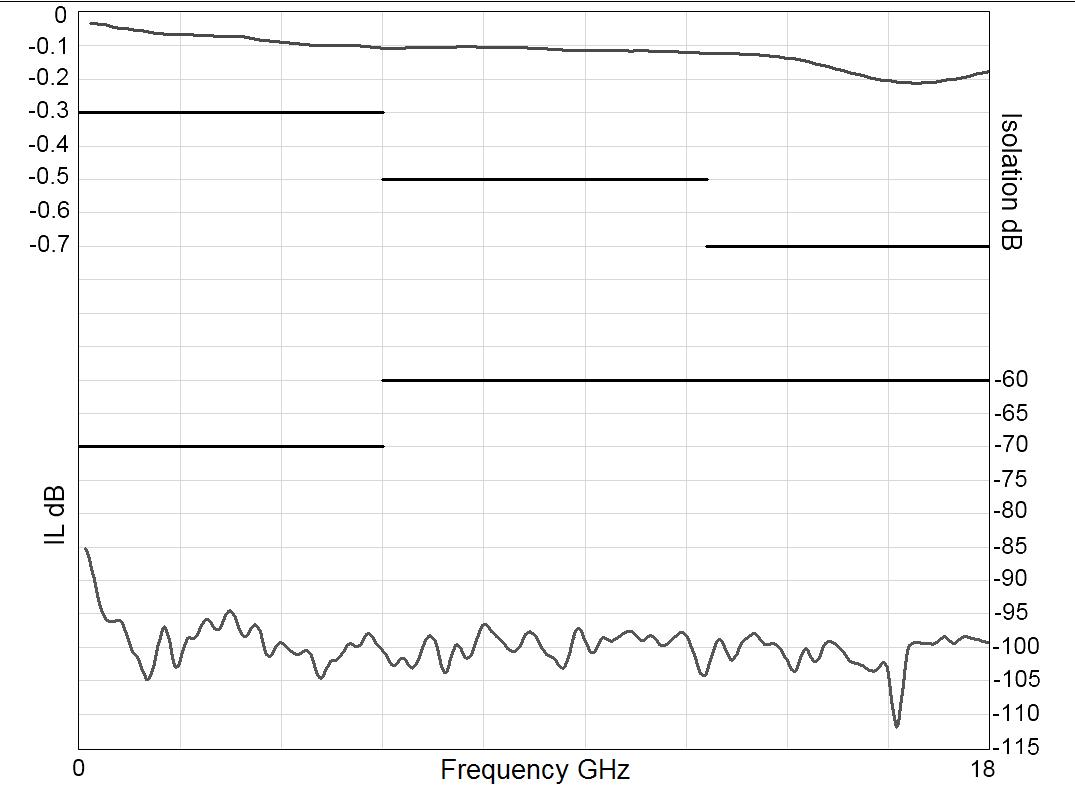
Frequency (GHz)
V.S.W.R
Frequency (GHz)
V.S.W.R
Frequency (GHz)
2-18 | SPDT SIMPLIFICATION IS OUR INNOVATION Visit www.radiall.com for more information
RAMSES Series
TYPICAL OUTLINE DRAWING
WITH D-SUB CONNECTOR WITH SOLDER PINS
ACCESSORIES
A printed circuit board interface connector (ordered separately) has been designed for easy mounting on terminals � For SPDT model R570 series = Radiall part number: R599 910 000
Notes
All dimensions are in millimeters [inches]. The PCB accessory pin number assignment is independant from the pin identification table of the switch.
SPDT | 2-19 SIMPLIFICATION IS OUR INNOVATION Visit www.radiall.com for more information
N TNC BNC A max (mm [inches]) 18 5 [0 709] 11 5 [0 433] 11 5 [0 433]
CONNECTORS
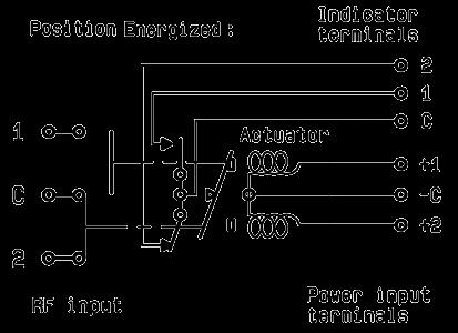
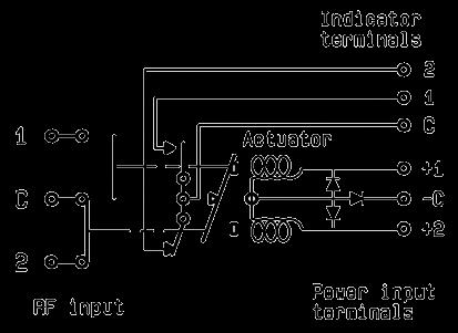
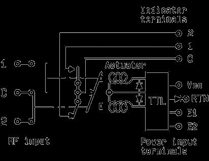
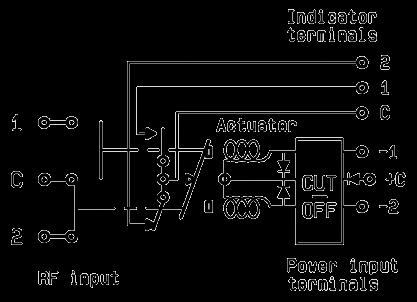
Electrical Schematics
COAXIAL SPDT
R570 SERIES
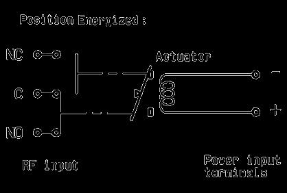
FAILSAFE
WITHOUT OPTION
R570-1-000
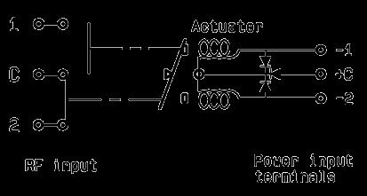
WITH SUPPRESSION DIODES
R570-1-030
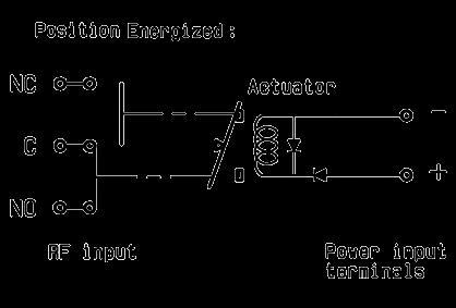
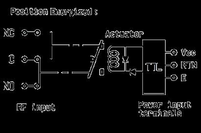
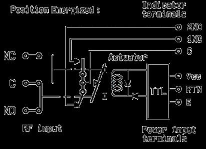
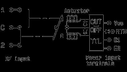
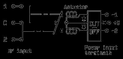
WITH TTL DRIVER (SUPRESSION DIODES ARE INCLUDED)
R570-1-100
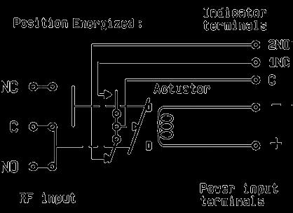
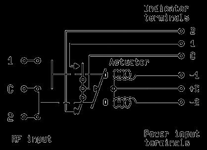
WITH INDICATOR CONTACT
R570-2-000
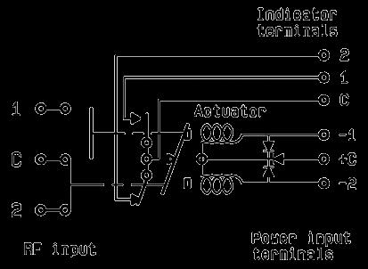
WITH SUPPRESSION DIODES & INDICATOR CONTACT
R570-2-030
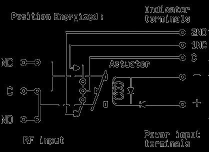
WITH TTL DRIVER & INDICATOR CONTACT (SUPRESSION DIODES ARE INCLUDED)
R570-2-100
2-20 | SPDT SIMPLIFICATION IS OUR INNOVATION Visit www.radiall.com for more information
Electrical Schematics
COAXIAL SPDT
R570 SERIES
LATCHING
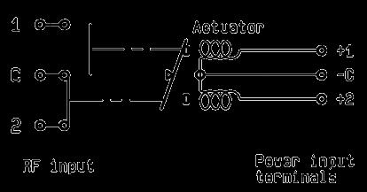
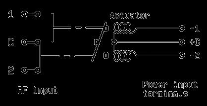
WITHOUT OPTION
R570-3-000
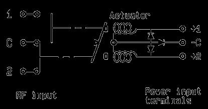
WITH SUPPRESSION DIODES
R570-3-030
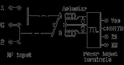
WITH TTL DRIVER (SUPRESSION DIODES ARE INCLUDED)
R570-3-100
WITH INDICATOR CONTACT
R570-4-000
WITH SUPPRESSION DIODES & INDICATOR CONTACT
R570-4-030
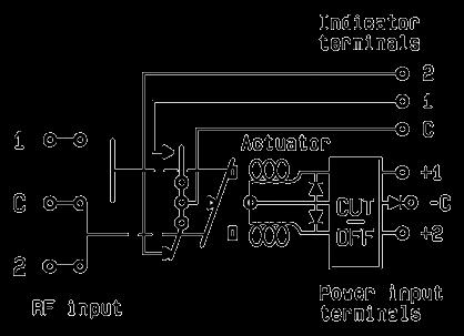
WITH TTL DRIVER & INDICATOR CONTACT (SUPRESSION DIODES ARE INCLUDED)
R570-4-100
SPDT | 2-21 SIMPLIFICATION IS OUR INNOVATION Visit www.radiall.com for more information
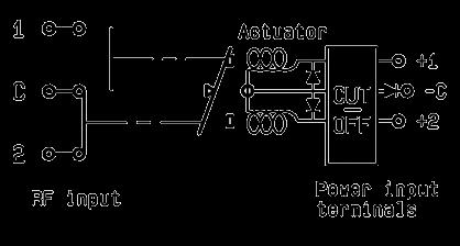
Electrical Schematics
COAXIAL SPDT (CONTINUED)
R570 SERIES
LATCHING
WITH CUT-OFF (SUPRESSION DIODES ARE INCLUDED)
R570-5-100
WITH CUT-OFF & TTL DRIVER (SUPRESSION DIODES ARE INCLUDED)
R570-5-100
WITH POSITIVE COMMON, NO OPTION
R570-3-010
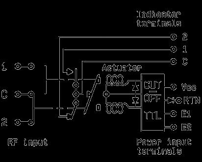
WITH CUT-OFF & INDICATOR CONTACT (SUPRESSION DIODES ARE INCLUDED)
R570-6-100
WITH CUT-OFF & INDICATOR CONTACT (SUPRESSION DIODES ARE INCLUDED)
R570-6-100
WITH POSITIVE COMMON & INDICATOR CONTACT
R570-5-010
2-22 | SPDT SIMPLIFICATION IS OUR INNOVATION Visit www.radiall.com for more information
Electrical Schematics
COAXIAL SPDT (CONTINUED)
R570 SERIES
WITH POSITIVE COMMON & SUPPRESSION DIODES
R570-3-040
WITH POSITIVE CUT-OFF (SUPRESSION DIODES ARE INCLUDED)
R570-5-010
LATCHING PIN IDENTIFICATION
WITH POSITIVE COMMON, SUPPRESSION (DIODES & INDICATOR CONTACT)
R570-4-040
WITH POSITIVE COMMON, CUT-OFF & INDICATOR CONTACT (SUPRESSION DIODES ARE INCLUDED)
R570-6-010
SPDT | 2-23 SIMPLIFICATION IS OUR INNOVATION Visit www.radiall.com for more information
Top View
TYPE PIN 1 2 3 4 6 7 8 Failsafe + –Failsafe + I C + – 2NO 1NC C Failsafe + TTL E RTN VCC Failsafe + I C + TTL E RTN VCC 2NO 1NC C Latching Latching + Cut-off -2 or +2 -1 or +1 +C or -C Latching + I �C � Latching + I C + Cut-off -2 or +2 -1 or +1 +C or -C 2 1 C Latching + TTL Latching + TTL + Cut-off E2 E1 RTN VCC Latching + TTL + I C Latching + TTL + I C + Cut-off E2 E1 RTN VCC 2 1 C
HIGH PERFORMANCE SPDT UP TO 40 GHz
SMA - SMA 2.9
PART NUMBER SELECTION
SERIES PREFIX
FREQUENCY RANGE
3: SMA up to 6 GHz
4: SMA up to 20 GHz
F: SMA up to 26 5 GHz
8: SMA 2 9 up to 40 GHz
TYPE
3: Latching [1]
4: Latching + I C [1]
5: Latching + S C O [1]
6: Latching + S C O + I C [1]
ACTUATOR VOLTAGE
3: 24 Vdc
7: 15 Vdc
SWITCH MODEL
1: Non-terminated SPDT switch
OPTIONS
1: Without option (positive common)
2: Compatible TTL driver
ACTUATOR TERMINALS
0: Solder pins
5: D-Sub connector
DOCUMENTATION
-: Certificate of conformity
C: Calibration certificate
R: Calibration certificate + RF curves
Radiall’s PLATINUM series switches are optimized to perform at a high level over an extended life cycle, with outstanding RF performance, and a guaranteed insertion loss repeatability of 0 03 dB over a life span of 10 million switching cycles PLATINUM series switches are perfect for automated test and measurement equipment, as well as signal monitoring devices.
Example of P/N: R595443125 is a SPDT SMA 20 GHz, latching, 24 Vdc, with TTL driver, Indicators, D-Sub connector.
R595
Notes
I.C.: Indicator contact - S.C.O.: Self Cut-Off
1. Suppression diodes are already included
2-24 | SPDT SIMPLIFICATION IS OUR INNOVATION Visit www.radiall.com for more information
Platinum Series
ENVIRONMENTAL SPECIFICATIONS
Operating temperature range -25 °C to + 75 °C
Storage temperature range -55 °C to +85 °C
Temperature cycling (MIL STD 202F, Method 107D, Cond.A) -55 °C to +85 °C (10 cycles)
Sine vibration operating (MIL STD 202, Method 204D, Cond.D) 10 - 2,000 Hz, 20 g
Random vibration operating 16.91 g (rms) 50-2,000 Hz 3 min/axis
Shock operating (MIL STD 202, Method 213B, Cond.G) 50 g / 11 ms, sawtooth
Humidity operating 15 to 95% relative humidity
Humidity storage (MIL STD 202, Method 106E, Cond.E) 65 °C, 95% RH, 10 days
Altitude operating 15 ft (4 600 meters)
Altitude storage (MIL STD 202, Method 105C, Cond.B) 50 ft (15 240 meters)
SPDT | 2-25 SIMPLIFICATION IS OUR INNOVATION Visit www.radiall.com for more information
Platinum Series
LATCHING Nominal operating voltage (across temperature range) Vdc 24 (24 to 30) 15 (12 to 20) Coil resistance at 23 °C (+/-10%) Ω 350 120 Operating current at 23 °C mA 68 125 TTL input High level 3 to 7 Volts: 800 µA max 7 Volts Low level 0 to 0 8 Volts: 20 µA max 0 8 Volts Switching time ms 15 Life (Min) SMA 10 million cycles SMA 2 9 5 million cycles
Weight
GENERAL SPECIFICATIONS OPERATING MODE
Actuator terminals D-Sub 9 pin female Solder pins
g 60
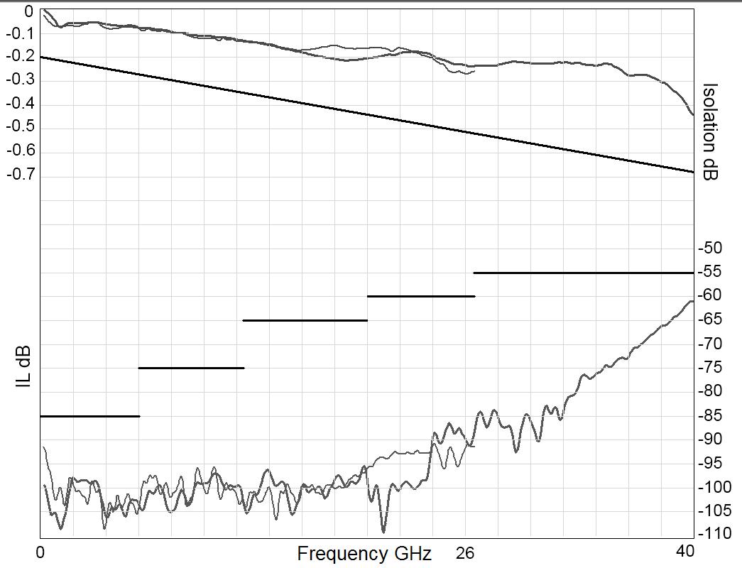
RF PERFORMANCE PART
INSERTION LOSS & ISOLATION Platinum Series
TYPICAL RF PERFORMANCE
Frequency (GHz)
V.S.W.R
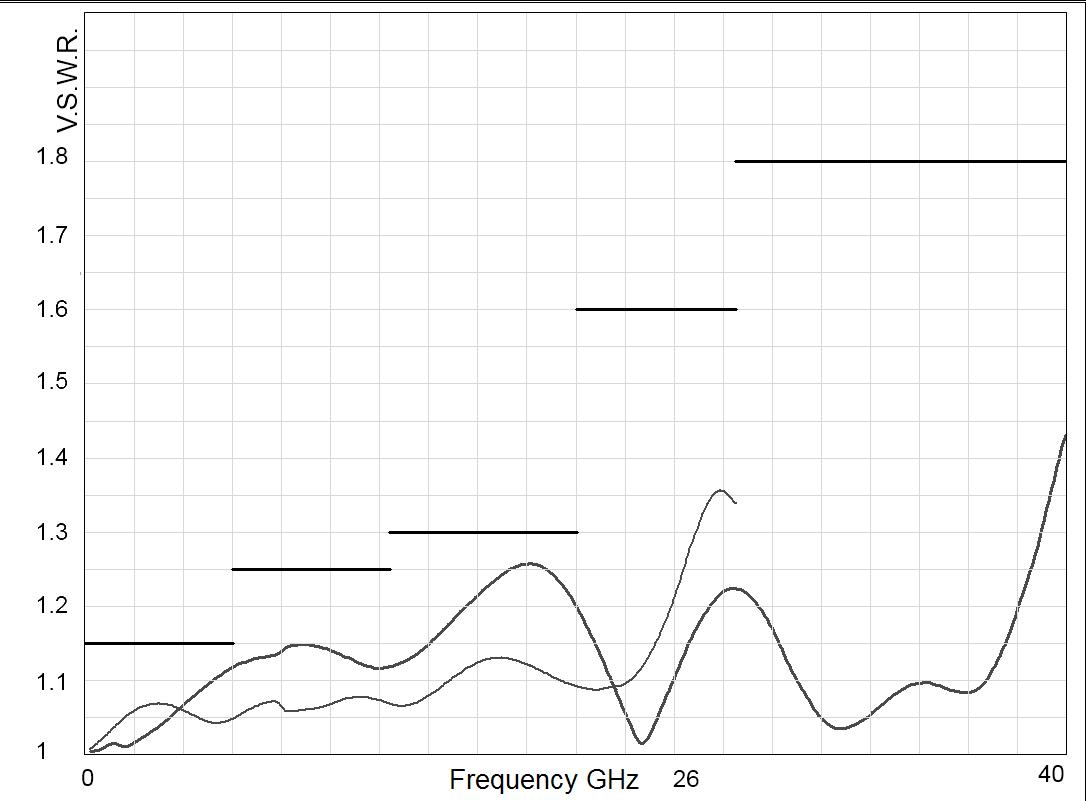
Frequency (GHz)
2-26 | SPDT SIMPLIFICATION IS OUR INNOVATION Visit www.radiall.com for more information
NUMBER R5953--1-- R5954--1-- R595F--1-- R5958--1-Frequency range GHz DC to 6 DC to 20 DC to 26.5 DC to 40
Ω 50
Loss (max) dB 0.20 + (0.45 / 26.5) × frequency (GHz) Isolation (min) dB 85 DC to 6 GHz 6 to 12 4 GHz 12 4 to 20 GHz 85 75 65 DC to 6 GHz 6 to 12 4 GHz 12 4 to 20 GHz 20 to 26 5 GHz 85 75 65 60 DC to 6 GHz 6 to 12 4 GHz 12 4 to 20 GHz 20 to 26 5 GHz 26 5 to 40 GHz 85 75 65 60 55 V S W R (max) 1 15 DC to 6 GHz 6 to 12 4 GHz 12 4 to 20 GHz 1 15 1 25 1 30 DC to 6 GHz 6 to 12 4 GHz 12 4 to 20 GHz 20 to 26 5 GHz 1 15 1 25 1 30 1 60 DC to 6 GHz 6 to 12 4 GHz 12 4 to 20 GHz 20 to 26 5 GHz 26 5 to 40 GHz 1 15 1 25 1 30 1 60 1 80 Repeatability (up to 10 million cycles at 25 °C) dB 0 03 dB maximun 0 05 dB maximun
Impedance
Insertion
SMA SMA 2.9
SWITCH MODEL: NON-TERMINATED SPDT SWITCH
The non-terminated SPDT switch is a single pole double throw switch. This switch is considered "break-before-make."
RF Schematic Diagram
POSITION E1
Position Indicator
Standard drive option “1” (Positive common):
• Connect pin +Vcc to supply (+20 Vdc to +32 Vdc)
• Select desired RF path by applying ground to the corresponding "close" pin (Ex: ground pin E1 to switch to position E1� RF path 1-2 closed and RF path 2-3 open)
• To open desired path and close the new RF path, connect ground to the corresponding "close" pin (Ex: ground pin E2 to open RF path 1-2 and close RF path 2-3)
POSITION E2
TTL drive option “2”
• Connect pin GND to ground
• Connect pin +Vcc to supply (+20 Vdc to +32 Vdc)
• Select (close) desired RF path by applying TTL "High" to the corresponding "drive" pin (Ex: apply TTL "High" to pin E1 to switch to position E1� RF path 1-2 closed and RF path 2-3 open)
• To open desired path and close the new RF path, apply TTL "High" to the "drive" pin which corresponds to the desired RF path (Ex: apply TTL “High” to pin E2)
SPDT | 2-27 SIMPLIFICATION IS OUR INNOVATION Visit www.radiall.com for more information
Platinum Series
D-Sub connector
Solder pins
Solder pins
D-Sub connector
STATE 22 STATE 11
SMA - SMA 2.9 TYPICAL OUTLINE DRAWING
WITH D-SUB CONNECTOR
WITH SOLDER PINS
CONNECTORS A MAX MM [INCHES]
[0� 303]
2 9 6 7 [0 264]
Notes All dimensions are in millimeters [inches].
2-28 | SPDT SIMPLIFICATION IS OUR INNOVATION Visit www.radiall.com for more information
SMA 7�7
SMA
Platinum Series
RF POWER RATING CHART
This graph is based on the following conditions:
• Ambient temperature: + 25 °C
• Sea level
• V.S.W.R.: 1 and cold switching
DERATING FACTOR VERSUS VSWR
The average power input must be reduced for load V S W R above 1:1
SPDT | 2-29 SIMPLIFICATION IS OUR INNOVATION Visit www.radiall.com for more information
Platinum Series
V.S.W.R.
Average
Frequency (GHz)
Power Rating (Watts)
Optional Features
OPTIONAL FEATURES
GENERAL
All miniature SPDT switches fitted with SMA, QMA, 2.4 mm or SMA 2.9 connectors can be delivered with 34 mm narrow width RF body�
Contact Radiall sales directly for availability.
EXAMPLES OF DEDICATED APPLICATION OPTIONS
SMA SPDT with a SINGLE input TTL driver� This option is available in a latching configuration upon special request Key advantages include less wires and easier connection�
A SP4T design up to 26 � 5 GHz with SMT relays mounted on a PCB fitted with UMP (Ultra Miniature Pressure) contact Various switching configurations can be designed according to your specific requests.
SPDT with MILC38999 circular connector for L band airbone applications
SPDT with D-sub connector can be designed�
SPDT models available for high power military applications (up to 100 watts CW from DC to 18 GHz).
2-30 | SPDT SIMPLIFICATION IS OUR INNOVATION Visit www.radiall.com for more information
SIMPLIFICATION IS OUR INNOVATION Visit www.radiall.com for more information SECTION 3 DP3T
SPDT TERMINATED
&
Section 3 Table of Contents
RAMSES SERIES
DP3T
ELECTRICAL SCHEMATICS
Coaxial DP3T and Terminated SPDT: R585 Series
PLATINUM SERIES High
DP3T PART NUMBER SELECTION GUIDE [1]
Notes TTL driver is already included for the 1, 3, 5 and 7 switch models of the RAMSES R585 series. Example of P/N: R585832000 is a DP3T SMA2.9 40 GHz, latching, 12 Vdc, without option, solder pins. 1. For part number creation and available options, see detailed part number selection for each series.
DP3T & SPDT TERMINATED | 3-1 Visit www.radiall.com for more information SIMPLIFICATION IS OUR INNOVATION
and Terminated SPDT up to 50 GHz: R585 Series 3-2 to 3-7
������������������������������������������������������������������������������������������������������� 3-8 to 3-13
performance
up to 40 GHz:
Series
Optional Features for DP3T Switches 3-24
DP3T and Terminated SPDT
R595
3-14 to 3-23 OPTIONAL FEATURES
DIGITAL POSITION R 1-3: 4: RF CONNECTORS 5: TYPE 6: VOLTAGE 7: SWITCH MODEL 8: OPTIONS 9: TERMINALS 10: DOCUMENTATION Series ConfigurationSMA 3 GHz SMA 6 GHz SMA 18 GHz SMA 20 GHz SMA 26 5 GHz SMA 2 � 9 40 GHz 2 4 mm 50 GHz Failsafe Latching Normally open 12 V 15 V 24 V 28 V DP3T SPDT Terminated Terminated 4 ports Bypass Without option Positive common Supression diodes Positive common and suppression diodes Solder pins D-Sub connector Certificate of conformity Calibration certificate Calibration certificate + RF curves RAMSES DP3T R585 3 - 4 - F 8 J 1 3 7 2 - - 3 0/1 2/3/4/5 6/7 0 1 3 4 0 - - -PLATINUM DP3T R595 - 3 - 4 F 8 - - 3 - - 7 3 - 5 2 3 0 1 - - 0 5 - C R
RAMSES Series
DP3T & TERMINATED SPDT UP TO 50 GHz
SMA - SMA 2.9 - 2.4 MM
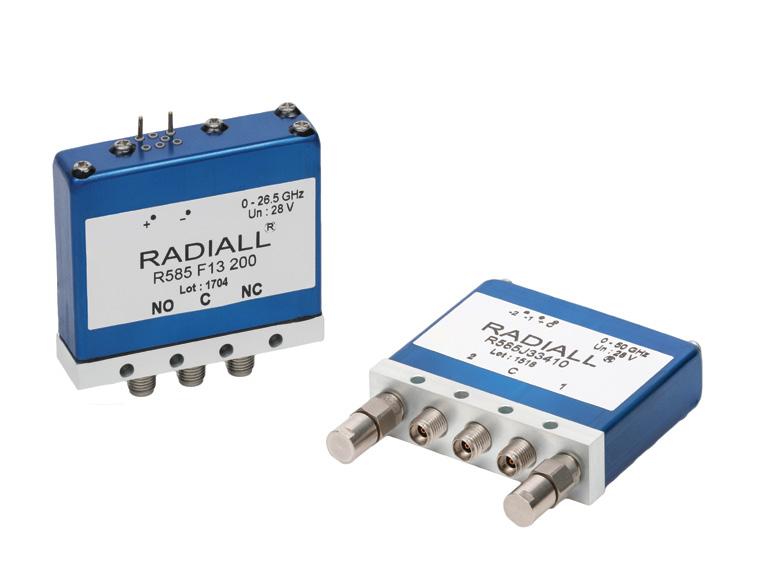
PART NUMBER SELECTION
SERIES PREFIX
RF CONNECTORS
3: SMA up to 3 GHz
4: SMA up to 18 GHz
F: SMA up to 26 � 5 GHz
8: SMA 2�9 up to 40 GHz [5]
J: 2 4 mm up to 50 GHz [4]
TYPE
1: Failsafe
2: Failsafe + I �C �
3: Latching
4: Latching + I �C �
5: Latching + S C O [1]
6: Latching + S C O + I C [1]
7: Normally open
8: Normally open + I C
ACTUATOR VOLTAGE
2: 12 Vdc
3: 28 Vdc
Radiall’s RAMSES DP3T and Terminated SPDT switches offer excellent reliability, high performance and operating frequencies from DC to 50 GHz. A full range of options are available within the RAMSES range in order to offer customers a complete solution�
These relays are dedicated to market applications including: defense, instrumentation and telecommunication
Example of P/N: R585423300 is a SPDT terminated SMA 18 GHz, failsafe, 28 Vdc, indicator contacts, internal terminations without TTL drivers and solder pins.
R585
Notes
I.C.: Indicator contact/S.C.O.: Self Cut-Off
1. Suppression diodes are already included in Self Cut-Off and TTL option
2. Polarity is not relevant to application for switches with TTL driver
3. Positive common shall be specified only with type 3, 4, 5, 6, 7 and 8 because
ACTUATOR TERMINALS
0: Solder pins
OPTIONS
0: Without option
1: Positive common [2 & 3]
3: With suppression diodes [1]
4: With suppression diodes and positive common [1, 2 & 3]
SWITCH MODEL
0: Non-terminated 5 port DP3T switch without TTL driver
1: Non-terminated 5 port DP3T switch with TTL driver [1 & 2]
2: Terminated SPDT switch without TTL driver / internal termination
3: Terminated SPDT switch with TTL driver / internal termination [1 & 2]
4: Terminated SPDT switch without TTL driver / external termination
5: Terminated SPDT switch with TTL driver / external termination [1 & 2]
6: Terminated 4 port bypass switch without TTL driver / external termination
7: Terminated 4 port bypass switch with TTL driver / external termination [1 & 2]
failsafe switches can be used with both polarities
4. Not available with switch model “2” and “3”
5. Connector SMA 2.9 is equivalent to "K connector®", registered trademark of Anritsu.
3-2 | DP3T & SPDT TERMINATED SIMPLIFICATION IS OUR INNOVATION Visit www.radiall.com for more information
RAMSES Series
GENERAL SPECIFICATIONS
Average power
See Power Rating Chart page 1-13 Internal terminations: 1 Watt CW into 50 Ohms
Switching time (max) ms 10
Actuator terminals Solder pins Operating temperature range
Vibration (MIL STD 202, Method 204D, cond.D)
Hz, 20 g Operating Shock (MIL STD 202, Method 213B,
RF PERFORMANCE
DP3T & SPDT TERMINATED | 3-3 Visit www.radiall.com for more information SIMPLIFICATION IS OUR INNOVATION
OPERATING MODE FAILSAFE LATCHING NORMALLY OPEN
operating
operating temperature) Vdc 12 28 12 28 12 28 (10 2 to13) (24 to 30) (10 2 to13) (24 to 32) (10 2 to13) (24 to 32) Coil resistance (+/-10%) Ω 24 138 29 175 47� 5 275 Nominal operating current at 23 °C mA 500 205 420 160 250 102
Nominal
voltage (across
TTL input High level 2 2 to 5 5 Volts 800 µA max 5 5 Volts Low level 0 to 0 8 Volts 20 µA max 5 5 Volts
W
30 V / 100 mA
Indicator rating 1
/
Life
SMA – SMA 2.9 2 million cycles for Normally open
internal terminated models 10 million cycles for all other products 2 4 mm 2 million cycles
(min)
and
SMA
2 9 -40 °C
°C 2 4 mm -25
°C
temperature
SMA -SMA
9 -55 °C to +85 °C 2 4 mm -40 °C to +85 °C
- SMA
to +85
°C to +70
Storage
range
2
100 g / 6 ms, ½ sine Operating
typical RF performance.
10-2,000
cond.C)
Notes See page 3-4 for
RANGE GH z V.S.W.R. (MAX) INSERTION LOSS (MAX) d B ISOLATION (MIN) dB IMPEDANCE Ω SMA DC - 3 DC - 18 DC - 26.5 DC - 3 1 20 0 20 80 50 3 - 8 1 30 0 30 70 8 - 12 4 1 40 0 40 60 12 4 - 18 1 50 0 50 60 18 - 26 5 1 70 0 70 55 SMA 2 �9 DC - 40 DC - 6 1 30 0 30 70 50 6 - 12 � 4 1� 40 0� 40 60 12 � 4 - 18 1� 50 0� 50 60 18 - 26 5 1 70 0 70 55 26 5 - 40 1 90 0 80 50 2 4 mm DC – 50 DC - 6 1 30 0 30 70 50 6 - 12 4 1 40 0 40 60 12 4 - 18 1 50 0 50 60 18 - 26 5 1 70 0 70 55 26 5 - 40 1 90 0 80 50 40 - 50 1 90 1 1 50
CONNECTORS FREQUENCY
RAMSES Series
R585 TYPICAL RF PERFORMANCE
Example: DP3T SMA up to 26.5 GHz
INSERTION LOSS & ISOLATION
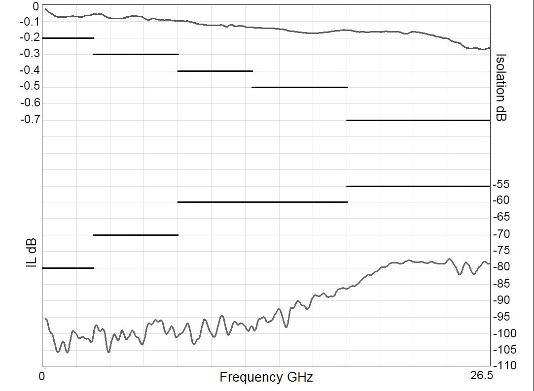
Frequency (GHz)
Example: DP3T SMA 2.9 up to 40 GHz
INSERTION LOSS & ISOLATION
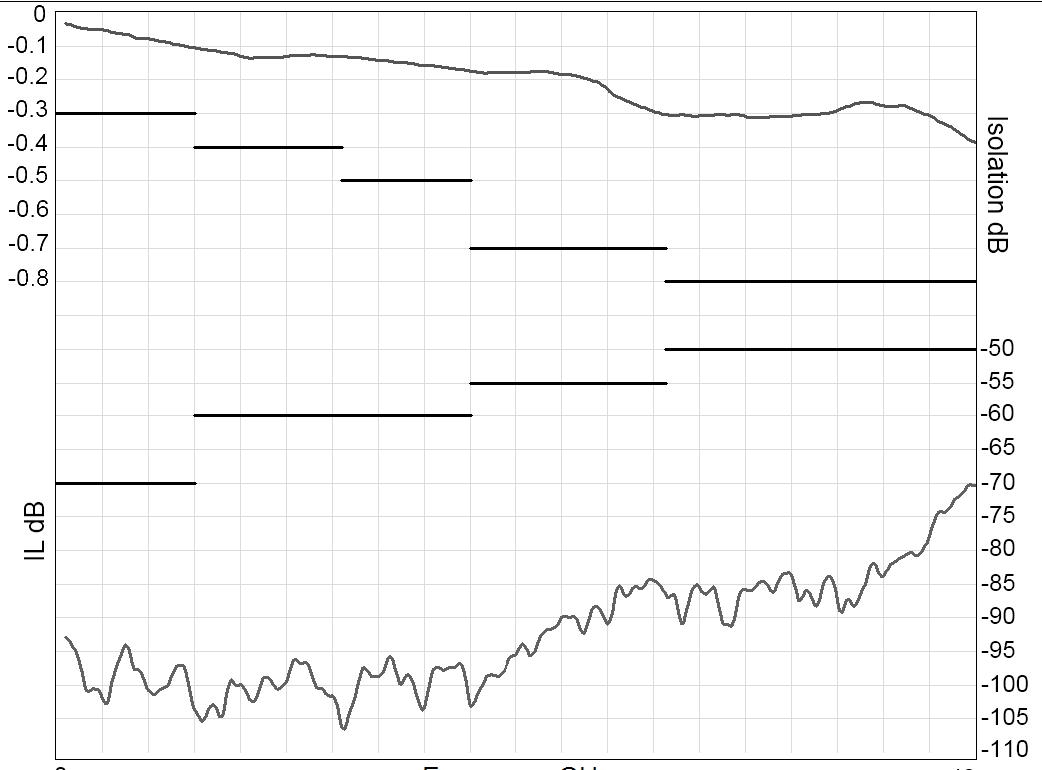
Frequency (GHz)
Example: DP3T 2.4 mm up to 50 GHz
INSERTION LOSS & ISOLATION
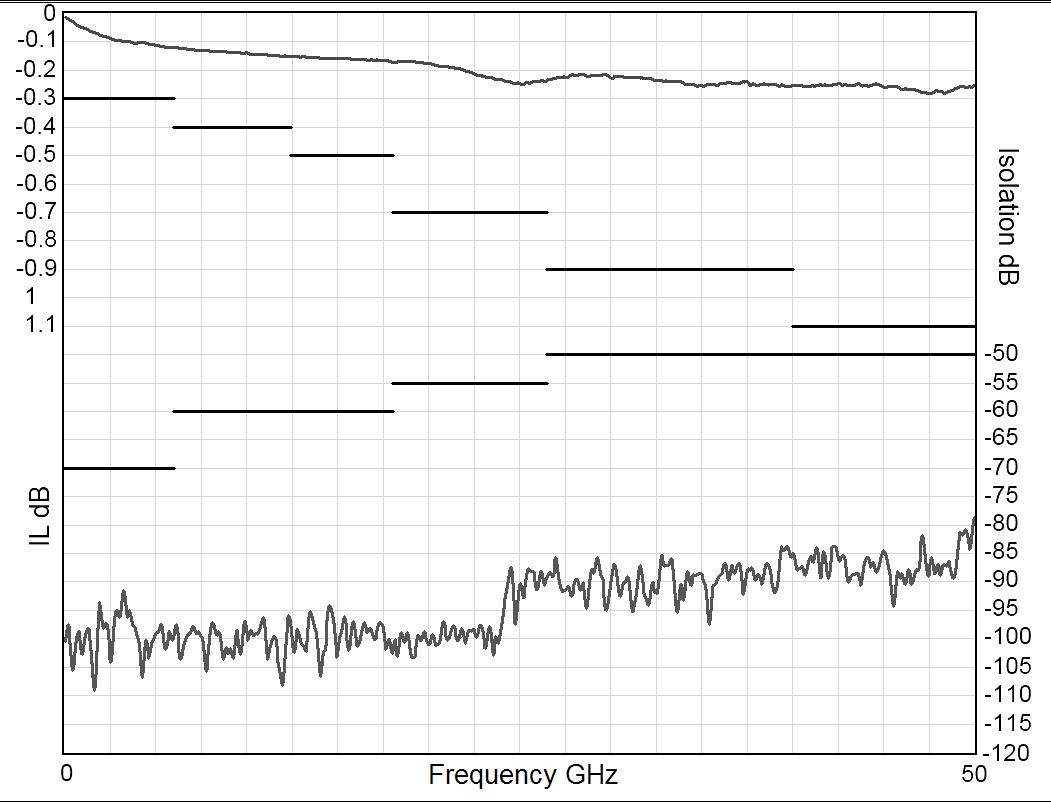
Frequency (GHz)
V.S.W.R
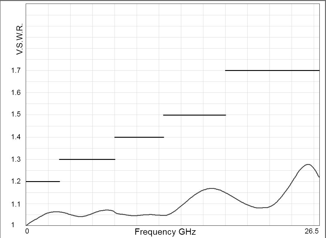
Frequency (GHz)
V.S.W.R
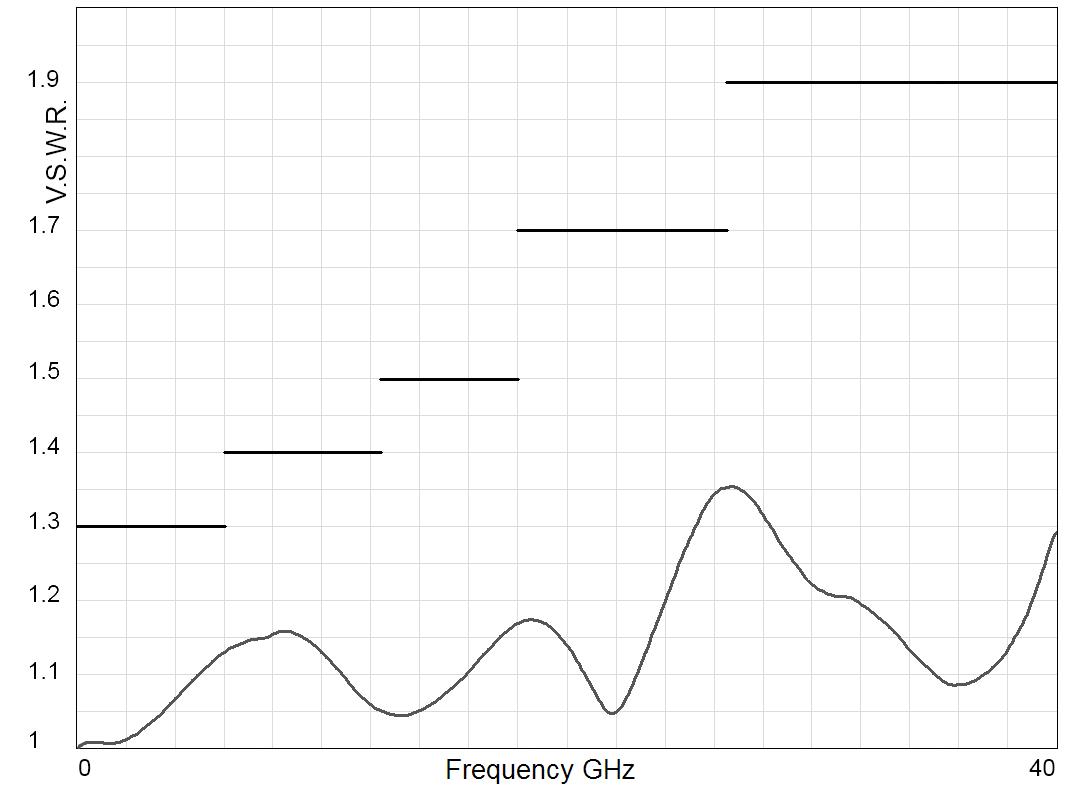
Frequency (GHz)
V.S.W.R
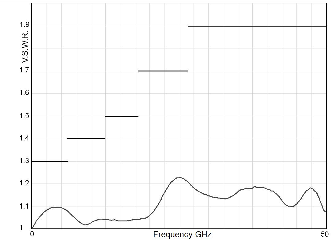
Frequency (GHz)
3-4 | DP3T & SPDT TERMINATED SIMPLIFICATION IS OUR INNOVATION Visit www.radiall.com for more information
TYPICAL OUTLINE DRAWING
TERMINATED SPDT SWITCH / EXTERNAL TERMINATIONS
R585 --- 4-R585 --- 5--
CONNECTORS
Notes
All dimensions are in millimeters [inches]. See page 3-13 for pin indentification.
TERMINATED SPDT SWITCH / INTERNAL TERMINATIONS R585 --- 2-R585 --- 3--
DP3T & SPDT TERMINATED | 3-5 Visit www.radiall.com for more information SIMPLIFICATION IS OUR INNOVATION
RAMSES Series
A MAX (MM [INCHES]) B MAX (MM [INCHES]) IF APPLICABLE SMA up to 18 GHz 7 7 [0 303] 13 5 [0 118] SMA up to 26 5 GHz 7 7 [0 303] 21 [0 827] SMA 2 9 up to 40 GHz 6 7 [0 264] 21 [0 827] 2
up
50 GHz 6 7 [0 264] 21 [0 827]
4 mm
to
NON-TERMINATED 5 PORT DP3T SWITCH
R585 --- 0-R585 --- 1--
CONNECTORS
Notes
All dimensions are in millimeters [inches]. See page 3-13 for pin indentification.
TERMINATED 4 PORT BYPASS SWITCH/EXTERNAL TERMINATION R585 --- 6-R585 --- 7--
3-6 | DP3T & SPDT TERMINATED SIMPLIFICATION IS OUR INNOVATION Visit www.radiall.com for more information
RAMSES Series
A MAX (MM [INCHES]) B MAX (MM [INCHES]) IF APPLICABLE SMA up to 18 GHz 7 7 [0 303] 13 5 [0 118] SMA up to 26 5 GHz 7 7 [0 303] 21 [0 827] SMA 2 9 up to 40 GHz 6 7 [0 264] 21 [0 827]
50 GHz 6 �7
264] 21
2 � 4 mm up to
[0 �
[0� 827]
RAMSES Series
R585 SERIES
ACCESSORIES
A printed circuit board interface connector (ordered separately) has been designed for easy mounting on terminals � For DP3T model R585 series = Radiall part number: R599910000.
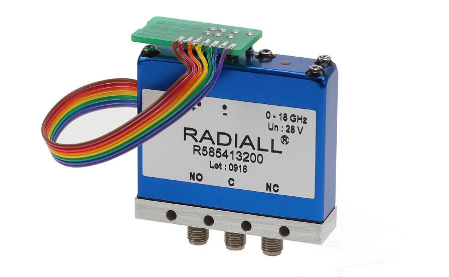
Notes
All dimensions are in millimeters [inches]. PCB accessory pin number assignment is independant from the pin identification table of the switch.
DP3T & SPDT TERMINATED | 3-7 Visit www.radiall.com for more information SIMPLIFICATION IS OUR INNOVATION
Electrical Schematics
COAXIAL DP3T & TERMINATED SPDT R585 SERIES FAILSAFE
WITHOUT OPTION
R585-1-000/R585-1-200/R585-1-400
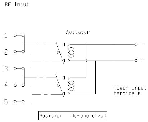
WITH SUPPRESSION DIODES
R585-1-030/R585-1-230/R585-1-430
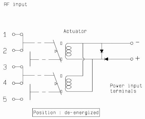
WITH TTL DRIVER (SUPRESSION DIODES ARE INCLUDED)
R585-1-100/R585-1-300/R585-1-500
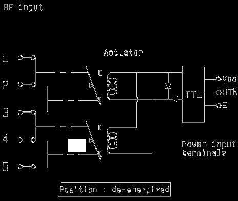
WITH INDICATOR CONTACT
R585-2-000/R585-2-200/R585-2-400
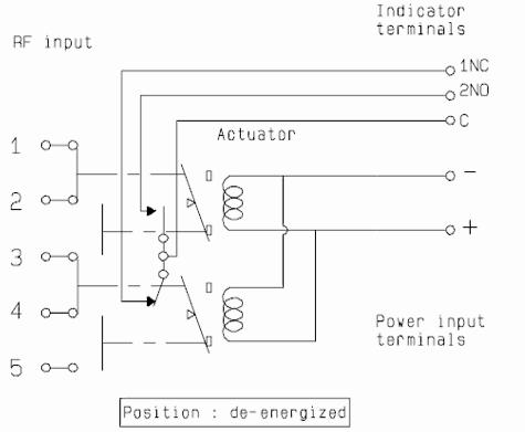
WITH SUPPRESSION DIODES & INDICATOR CONTACT
R585-2-030/R585-2-230/R585-2-430
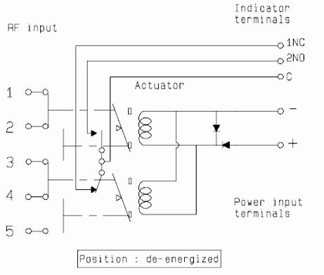
WITH TTL DRIVER & INDICATOR CONTACT (SUPRESSION DIODES ARE INCLUDED)
R585-2-100/R585-2-300/R585-2-500
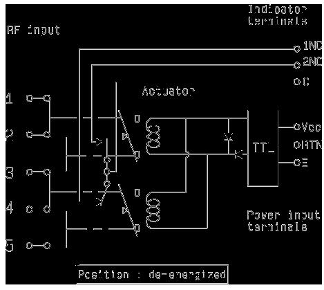
3-8 | DP3T & SPDT TERMINATED SIMPLIFICATION IS OUR INNOVATION Visit www.radiall.com for more information
Electrical Schematics
COAXIAL DP3T & TERMINATED SPDT
R585 SERIES
NORMALLY OPEN
WITHOUT OPTION
R585-7-000/R585-7-200/R585-7-400
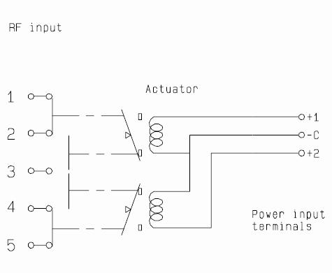
WITH SUPPRESSION DIODES
R585-7-030/R585-7-230/R585-7-430
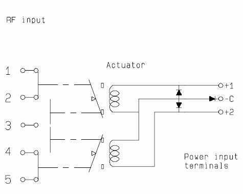
WITH TTL DRIVER (SUPRESSION DIODES ARE INCLUDED)
R585-7-100/R585-7-300/R585-7-500
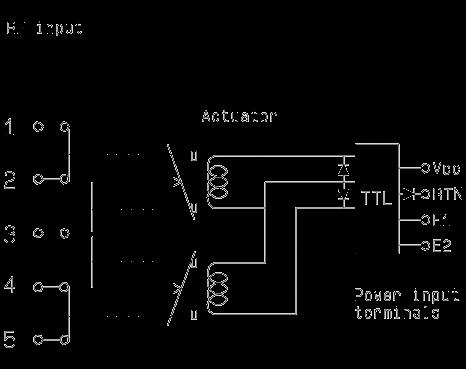
WITH INDICATOR CONTACT
R585-8-000/R585-8-200/R585-8-400
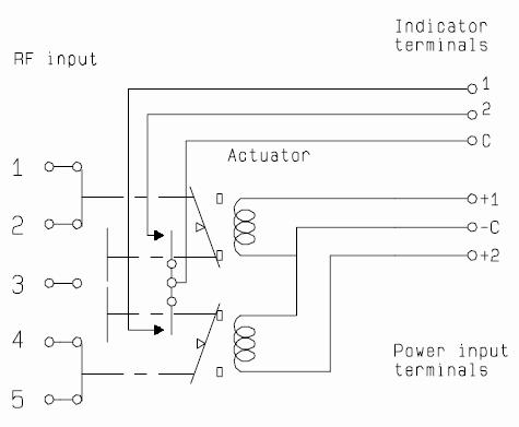
WITH SUPPRESSION DIODES & INDICATOR CONTACT
R585-8-030/R585-8-230/R585-8-430
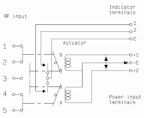
WITH TTL DRIVER & INDICATOR CONTACT (SUPRESSION DIODES ARE INCLUDED)
R585-8-100/R585-8-300/R585-8-500
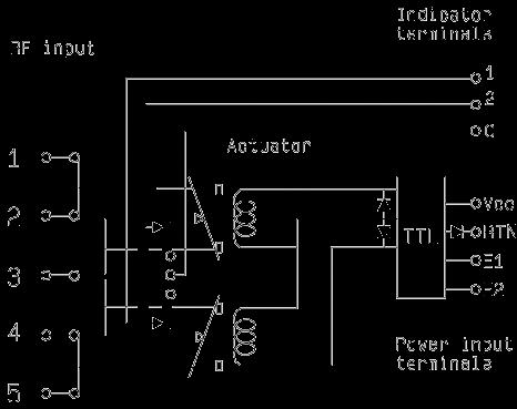
DP3T & SPDT TERMINATED | 3-9 Visit www.radiall.com for more information SIMPLIFICATION IS OUR INNOVATION
Electrical Schematics
COAXIAL DP3T & TERMINATED SPDT
R585 SERIES
NORMALLY OPEN & LATCHING
WITH POSITIVE COMMON, NO OPTION
R585-7-010/R585-7-210/R585-7-410
WITH POSITIVE COMMON & SUPPRESSION DIODES
R585-7-040/R585-7-240/R585-7-440
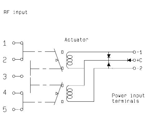
WITHOUT OPTION
R585-3-000/R585-3-200/R585-3-400
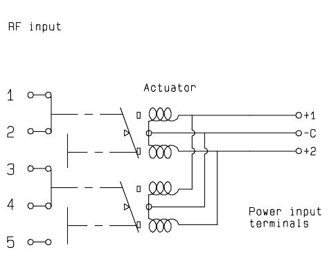
WITH POSITIVE COMMON & INDICATOR CONTACT
R585-8-010/R585-8-210/R585-8-410
WITH POSITIVE COMMON, INDICATOR CONTACT & SUPPRESSION DIODES
R585-8-040/R585-8-240/R585-8-440
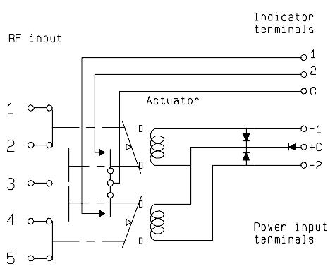
WITH INDICATOR CONTACT
R585-4-000/R585-4-200/R585-4-400
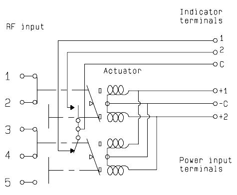
3-10 | DP3T
SIMPLIFICATION IS OUR INNOVATION Visit www.radiall.com for more information
& SPDT TERMINATED
Electrical Schematics
COAXIAL DP3T & TERMINATED SPDT
R585 SERIES
LATCHING
WITH SUPPRESSION DIODES
R585-3-030/R585-3-230/R585-3-430
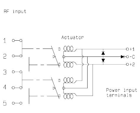
WITH TTL DRIVER (SUPPRESSION DIODES ARE INCLUDED)
R585-3-100/R585-3-300/R585-3-500
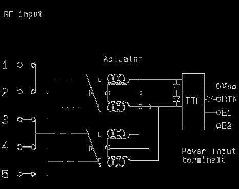
WITH CUT-OFF (SUPRESSION DIODES ARE INCLUDED)
R585-5-000/R585-5-200/R585-5-400
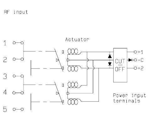
WITH SUPPRESSION DIODES & INDICATOR CONTACT
R585-4-030/R585-4-230/R585-4-430
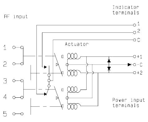
WITH TTL DRIVER & INDICATOR CONTACT
(SUPPRESSION DIODES ARE INCLUDED)
R585-4-100/R585-4-300/R585-4-500

WITH CUT-OFF & INDICATOR CONTACT (SUPRESSION DIODES ARE INCLUDED)
R585-6-000/ R585-6-200/R585-6-400
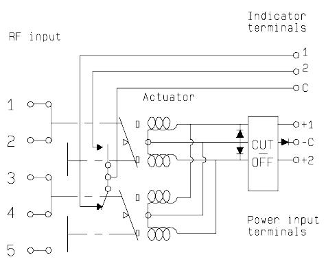
DP3T & SPDT TERMINATED | 3-11 Visit www.radiall.com for more information SIMPLIFICATION IS OUR INNOVATION
Electrical Schematics
COAXIAL DP3T & TERMINATED SPDT (CONTINUED)
R585 SERIES
LATCHING
WITH CUT-OFF & TTL DRIVER (SUPPRESSION DIODES ARE INCLUDED)
R585-5-100/R585-5-300/R585-5-500
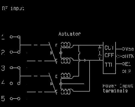
WITH POSITIVE COMMON, NO OPTION
R585-3-010/R585-3-210/R585-3-410
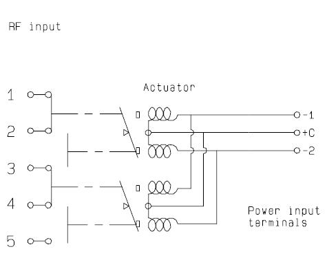
WITH POSITIVE COMMON & SUPPRESSION DIODES
R585-3-040/R585-3-240/R585-3-440
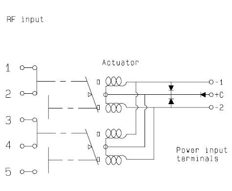
WITH CUT-OFF, TTL DRIVER & INDICATOR CONTACT (SUPPRESSION DIODES ARE INCLUDED)
R585-6-100/R585-6-300/R585-6-500

WITH POSITIVE COMMON & INDICATOR CONTACT
R585-4-010/R585-4-210/R585-4-410
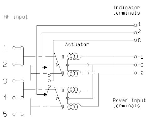
WITH POSITIVE COMMON, SUPPRESSION DIODES & INDICATOR CONTACT R585-4-040/R585-4-240/R585-4-440
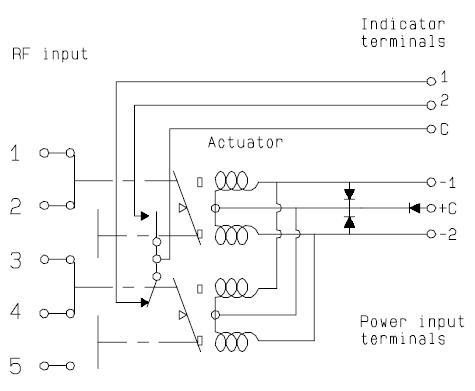
3-12 | DP3T & SPDT TERMINATED SIMPLIFICATION IS OUR INNOVATION Visit www.radiall.com for more information
Electrical Schematics
COAXIAL DP3T & TERMINATED SPDT (CONTINUED)
R585 SERIES
LATCHING
WITH POSITIVE COMMON & CUT-OFF (SUPPRESSION DIODES ARE INCLUDED)
R585-5-010/R585-5-210/R585-5-410
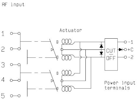
PIN IDENTIFICATION
WITH POSITIVE COMMON, CUT-OFF & INDICATOR CONTACT (SUPPRESSION DIODES ARE INCLUDED)
R585-6-010/R585-6-210/R585-6-410
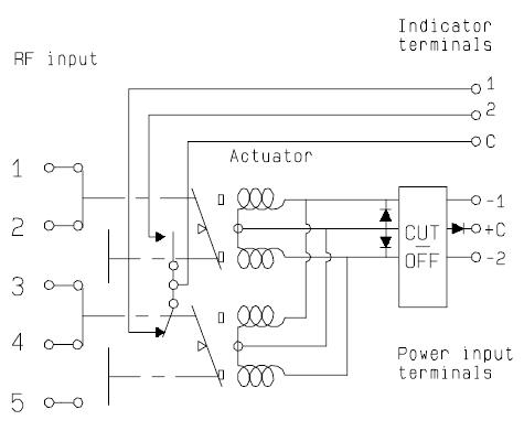
DP3T & SPDT TERMINATED | 3-13 Visit www.radiall.com for more information SIMPLIFICATION IS OUR INNOVATION
TYPE PIN 1 2 3 4 6 7 8 Failsafe + –Failsafe + I C + – 2NO 1NC C Failsafe + TTL E RTN VCC Failsafe + I �C � + TTL E RTN VCC 2N0 1NC C Latching Latching + Cut-off -2 or +2 -1 or +1 +C or -C Latching + I C Latching + I.C. + Cut-off -2 or +2 -1 or +1 +C or -C 2 1 C Latching + TTL Latching + TTL + Cut-off E2 E1 RTN VCC
TTL
C Latching + TTL + I C Cut-off E2 E1 RTN VCC 2 1 C Normally open -2 or +2 -1 or +1 +C or -C Normally open + I �C � -2 or +2 -1 or +1 +C or -C 2 1 C Normally open + TTL E2 E1 RTN VCC Normally open + TTL + I �C � E2 E1 RTN VCC 2 1 C Top View
Latching +
+ I
HIGH PERFORMANCE DP3T & TERMINATED SPDT UP TO 40 GHz
SMA - SMA 2.9
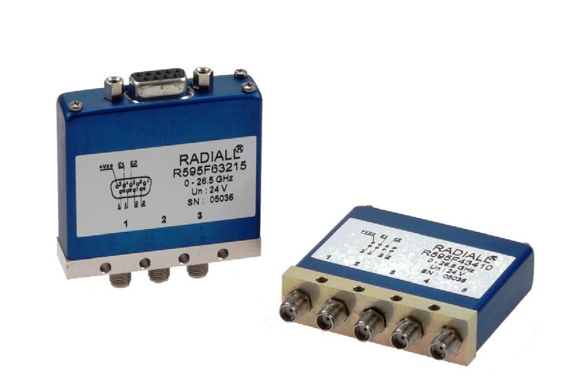
PART NUMBER SELECTION
SERIES PREFIX
RF CONNECTORS
3: SMA up to 6 GHz [2]
4: SMA up to 20 GHz [2]
F: SMA up to 26 � 5 GHz [2]
8: SMA 2�9 up to 40 GHz [1 & 3]
TYPE
3: Latching
4: Latching + I C
5: Latching + S �C �O�
6: Latching + S �C �O� + I �C �
ACTUATOR VOLTAGE
3: 24 Vdc
7: 15 Vdc
SWITCH MODEL
2: Terminated SPDT switch
3: Terminated 4 port bypass switch
4: Non-terminated 5 port DP3T switch
OPTIONS
1: Without option (positive common)
2: Compatible TTL driver
ACTUATOR TERMINALS
0: Solder pins
5: D-Sub connector
DOCUMENTATION
-: Certificate of conformity
C: Calibration certificate
R: Calibration certificate + RF curves
Radiall’s PLATINUM series switches are optimized to perform at a high level over an extended life cycle. With outstanding RF performance, and a guaranteed insertion loss repeatability of 0�03 dB over a life span of 10 million switching cycles � PLATINUM series switches are perfect for automated test and measurement equipment, as well as signal monitoring devices
Example of P/N: R595F63215 is a Terminated SPDT SMA 26.5 GHz, latching with Self Cut-Off, 24 Vdc, Indicators, D-Sub connector.
R595
Notes
I.C.: Indicator contact/S.C.O.: Self Cut-Off.
1. Connector SMA 2.9 is equivalent to "K connector ®", registered trademark of Anritsu.
2. The terminated models are fitted with internal terminations.
3. The terminated models are fitted with external terminations.
3-14 | DP3T & SPDT TERMINATED SIMPLIFICATION IS OUR INNOVATION Visit www.radiall.com for more information
Platinum Series
GENERAL SPECIFICATIONS
OPERATING MODE LATCHING
Nominal operating voltage (across operating temperature) Vdc 24 (20 to 32) 15 (12 to 20) Coil resistance (+/-10%) Ω
operating current at 23 °C mA
Average power
TTL input
High Level
RF path - Cold switching: see Power Chart on page 3-23 Hot switching: 1 Watt CW
Internal terminations - 1 Watt average into 50 Ω
External terminations - 1 Watt average into 50 Ω
3 to 7 V: 800 µA max at 7 V
Low Level 0 to 0 8 V: 20 µA max at 0 8 V
Switching time (max) ms 15
Life (min)
10 million cycles SMA 2 9 5 million cycles
Connectors SMA - SMA 2 �9
Actuator terminals
D-Sub 9 pin female Solder pins
Weight g < 100
ENVIRONMENTAL SPECIFICATIONS
Operating temperature range
Storage temperature range
-25 °C to +75 °C
-55 °C to +85 °C
Temperature cycling (MIL STD 202F, Method 107D, Cond.A) -55 °C to +85 °C (10 cycles)
Sine vibration operating (MIL STD 202, Method 204D, Cond.D) 10-2,000 Hz, 20 g
Random vibration operating 16.91 G (rms) 50-2,000 Hz 3 min/axis
Shock operating (MIL STD 202, Method 213B, Cond.G) 50 g/11 ms, sawtooth
Humidity operating 15 to 95% relative humidity
Humidity storage (MIL STD 202, Method 106E, Cond.E)
65 °C, 95% RH, 10 days
Altitude operating 15,000 ft (4,600 meters)
Altitude storage (MIL STD 202, Method 105C, Cond.B) 50,000 ft (15,240 meters)
DP3T & SPDT TERMINATED | 3-15 Visit www.radiall.com for more information SIMPLIFICATION IS OUR INNOVATION
175
140
60 Nominal
250
SMA
Platinum Series
RF PERFORMANCE
V.S.W.R INSERTION LOSS & ISOLATION
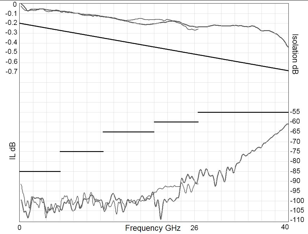
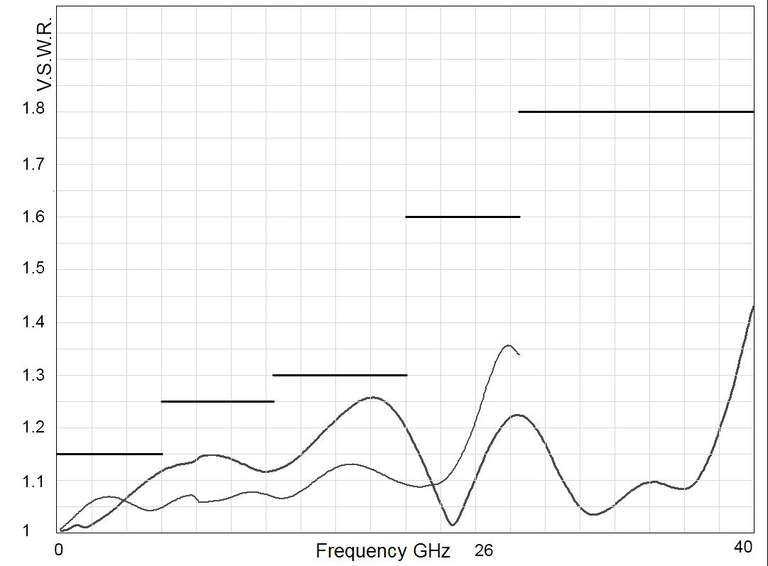
3-16 | DP3T & SPDT TERMINATED SIMPLIFICATION IS OUR INNOVATION Visit www.radiall.com for more information
R5953----- R5954----- R595F----- R5958----Frequency Range GHz DC to 6 DC to 20 DC to 26.5 DC to 40
Ω 50 Insertion Loss (max) dB 0� 20 + (0� 45 / 26 � 5) x frequency (GHz) Isolation (min) 85 DC to 6 GHz 6 to 12 4 GHz 12 4 to 20 GHz 85 75 65 DC to 6 GHz 6 to 12 � 4 GHz 12 4 to 20 GHz 20 to 26 5 GHz 85 75 65 60 DC to 6 GHz 6 to 12 � 4 GHz 12 4 to 20 GHz 20 to 26 5 GHz 26 5 to 40 GHz 85 75 65 60 55 V S W R (max) 1 15 DC to 6 GHz 6 to 12 4 GHz 12 4 to 20 GHz 1 15 1 25 1 30 DC to 6 GHz 6 to 12 4 GHz 12 4 to 20 GHz 20 to 26 5 GHz 1 15 1 25 1 30 1 60 DC to 6 GHz 6 to 12 4 GHz 12 4 to 20 GHz 20 to 26 5 GHz 26 5 to 40 GHz 1 15 1 25 1 30 1 60 1 80 Repeatability (Up to 10 million cycles at 25 °C) 0 03 dB maximum 0 05 dB maximum Frequency (GHz) Frequency (GHz) SMA SMA 2.9
PART NUMBER
Impedance
Platinum Series
SWITCH MODEL: NON-TERMINATED SPDT SWITCH
RF Schematic Diagram
POSITION E1
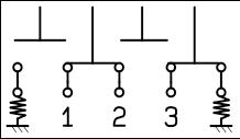
Position Indicator
The terminated SPDT switch is a single pole double throw switch where unused ports are terminated into 50 ohms. This switch is considered a “break-before-make.” STATE 22 STATE 11
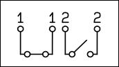
Standard drive option “1”
(Positive common):
• Connect pin +Vcc to supply (+20 Vdc to +32 Vdc)
• Select desired RF path by applying ground to the corresponding "close" pin (Ex: ground pin E1 to switch to position E1� RF path 1-2 closed and RF path 2-3 open)
• To open desired path and close the new RF path, connect ground to the corresponding "close" pin (Ex: ground pin E2 to open RF path 1-2 and close RF path 2-3)
POSITION E2
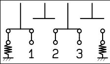
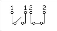
TTL drive option “2”
• Connect pin GND to ground
• Connect pin +Vcc to supply (+20 Vdc to +32 Vdc)
• Select (close) desired RF path by applying TTL "High" to the corresponding "drive" pin (Ex: apply TTL "High" to pin E1 to switch to position E1� RF path 1-2 closed and RF path 2-3 open)
• To open desired path and close the new RF path, apply TTL "High" to the "drive" pin which corresponds to the desired RF path (Ex: apply TTL “High” to pin E2 to open RF path 1-2 and close RF path 2-3)
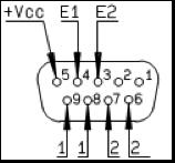
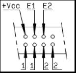
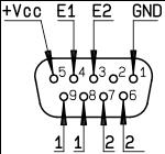
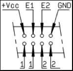
DP3T & SPDT TERMINATED | 3-17 Visit www.radiall.com for more information SIMPLIFICATION IS OUR INNOVATION
Platinum Series
Solder pins
Solder pins
D-Sub connector
D-Sub connector
SWITCH MODEL: TERMINATED SPDT SWITCH
WITH SOLDER PINS WITH D-SUB CONNECTOR
CONNECTORS
Notes All dimensions are in millimeters [inches].
3-18 | DP3T & SPDT TERMINATED SIMPLIFICATION IS OUR INNOVATION Visit www.radiall.com for more information
A MAX (MM
B MAX (MM
SMA 7 7
1 5
SMA 2 9 6 7
21
[INCHES])
[INCHES]) TERMINATIONS
[0 303]
[0 059] Internal
[0 264]
[0 827] External
Platinum
Series
SWITCH MODEL: TERMINATED 4-PORT BYPASS SWITCH
The terminated 4 port bypass switch can terminate into the 50 ohms device under test
This switch is considered a “break-before-make.”
RF Schematic Diagram
POSITION E1
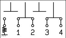
Position Indicators
Standard drive option “1” (Positive common):
• Connect pin +Vcc to supply (+20 Vdc to +32 Vdc)�
• Select desired RF path by applying ground to the corresponding "close" pin (Ex: ground pin E1 to switch to position E1 RF path 1-2 and RF path 3-4 closed and RF path 2-3 open)
• To open desired path and close the new RF path, connect ground to the corresponding "close" pin (Ex: ground pin E2 to open RF path 1-2 and 3-4 and close RF path 2-3)�
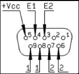
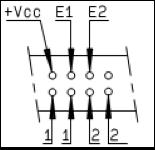
POSITION E2
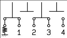
TTL drive option “2”
• Connect pin GND to ground
• Connect pin +Vcc to supply (+20 Vdc to +32 Vdc)
• Select (close) desired RF path by applying TTL "High" to the corresponding "drive" pin (Ex: apply TTL "High" to pin E1 to switch to position E1 RF path 1-2 and 3-4 closed and RF path 2-3 open)
• To open desired path and close the new RF path, apply TTL "High" to the "drive" pin which corresponds to the desired RF path (Ex: apply TTL “High” to pin E2 to open RF path 1-2 and 3-4 and close RF path 2-3)
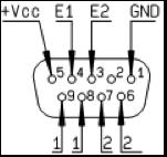
DP3T & SPDT TERMINATED | 3-19 Visit www.radiall.com for more information SIMPLIFICATION IS OUR INNOVATION
Series
Platinum
Solder pins
Solder pins
D-Sub connector
D-Sub connector
STATE
STATE
22
11
CONNECTORS
Notes
All dimensions are in millimeters [inches].
3-20 | DP3T & SPDT TERMINATED SIMPLIFICATION IS OUR INNOVATION Visit www.radiall.com for more information
A MAX
B MAX
SMA 7
1
Internal SMA 2 9 6 7
21
External
(MM [INCHES])
(MM [INCHES]) TERMINATIONS
7 [0 303]
5 [0 059]
[0 264]
[0 827]
WITH SOLDER PINS WITH D-SUB CONNECTOR Platinum Series
SWITCH MODEL: TERMINATED 5-PORT DP3T SWITCH
The non-terminated 5 port DP3T switch can be used as SPDT with high power terminations, as a bypass switch. In this application, the fifth port can be terminated externally with a high power termination. These switches are considered a "break-before-make�"
RF Schematic Diagram
POSITION E1
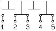
Position Indicators
POSITION E2
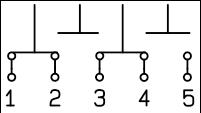
STATE 22 STATE 11
Standard drive option “1” (Positive common):
• Connect pin +Vcc to supply (+20 Vdc to +32 Vdc)
• Select desired RF path by applying ground to the corresponding "close" pin (Ex: ground pin E1 to switch to position E1� RF path 2-3 and RF path 4-5 closed and RF path 1-2 and RF path 3-4 open)
• To open desired path and close the new RF path, connect ground to the corresponding "close" pin (Ex: ground pin E2 to open RF path 2-3 and 4-5 and close RF path 1-2 and 3-4)
TTL drive option “2”
• Connect pin GND to ground
• Connect pin +Vcc to supply (+20 Vdc to +32 Vdc)
• Select (close) desired RF path by applying TTL "High" to the corresponding "drive" pin (Ex: apply TTL "High" to pin E1 to switch to position E1� RF path 2-3 and RF path 4-5 closed and RF path 1-2 and 3-4 open)
• To open desired path and close the new RF path, apply TTL "High" to the "drive" pin which corresponds to the desired RF path� (Ex: apply TTL “High” to pin E2 to open RF path 2-3 and 4-5 and close RF path 1-2 and 3-4)
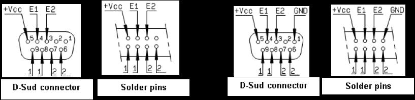
DP3T & SPDT TERMINATED | 3-21 Visit www.radiall.com for more information SIMPLIFICATION IS OUR INNOVATION Platinum Series
D-Sub connector
NON-TERMINATED 5 PORT DP3T SWITCH
WITH SOLDER PINS WITH D-SUB CONNECTOR
Notes
CONNECTORS A MAX (MM [INCHES])
7 [0 303] SMA 2 9
All dimensions are in millimeters [inches].
7 [0 264]
3-22 | DP3T & SPDT TERMINATED SIMPLIFICATION IS OUR INNOVATION Visit www.radiall.com for more information
7
6
SMA
Platinum Series
POWER RATING CHART
This graph is based on the following conditions:
• Ambient temperature: + 25 °C
• Sea level
• V.S.W.R.: 1 and cold switching
DERATING FACTOR VERSUS VSWR
The average power input must be reduced for load V S W R above 1:1
DP3T & SPDT TERMINATED | 3-23 Visit www.radiall.com for more information SIMPLIFICATION IS OUR INNOVATION
Platinum Series
V.S.W.R.
Frequency
Average Power Rating
(GHz)
(Watts)
Optional Features
OPTIONAL FEATURES FOR DP3T SWITCHES
GENERAL
RADIALL DP3T / SPDT terminated are only designed with SMA, SMA 2.9 and 2.4 mm connectors. For all other connectors (N, BNC etc.), the same function as SPDT terminated can be easily performed with a standard DPDT and an external load�
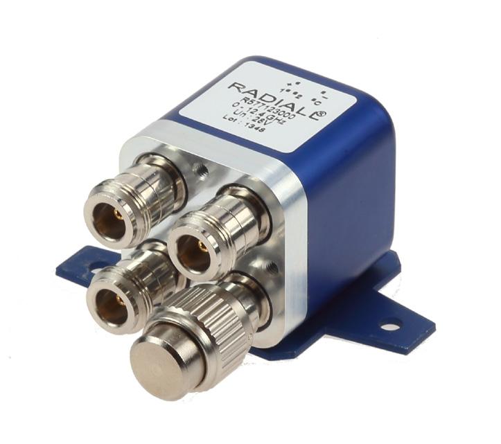
EXAMPLES OF DEDICATED APPLICATIONS
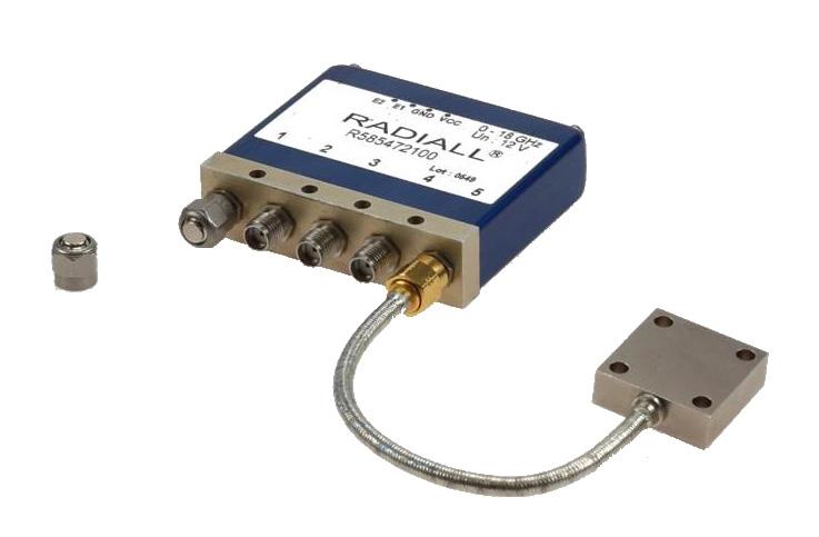
This SPDT terminated switch is composed of a DP3T with SMA connectors, and cable load for medium power terminations The Key advantage of this solution is the ability to mount the switch with external terminations at the desired power level�
POS 1 : J1 to J2 / J3 to load
POS 2 : J1 to J3 / J2 to load LOAD
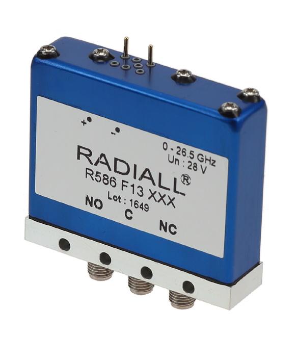
This is an example of an SPDT terminated switch that was designed with two seperate coils for a specific test network application
3-24 | DP3T & SPDT TERMINATED SIMPLIFICATION IS OUR INNOVATION Visit www.radiall.com for more information
LOA D
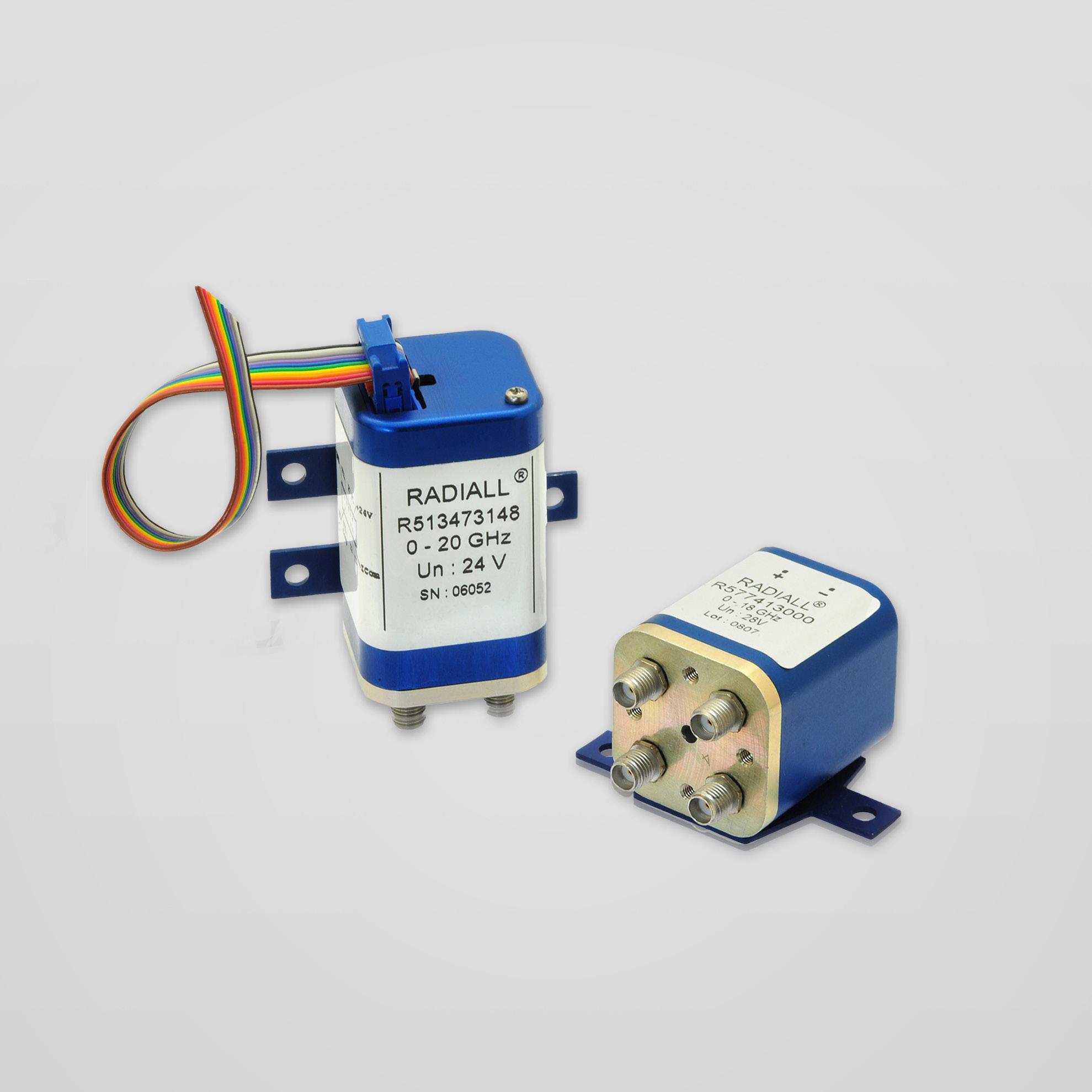
SIMPLIFICATION IS OUR INNOVATION Visit www.radiall.com for more information SECTION 4 DPDT
Section 4 Table of Contents
RAMSES SERIES
DPDT up to 50 GHz: R577 miniature
DPDT up to 12.4 GHz RAMSES Concept: N, BNC and TNC models
ELECTRICAL SCHEMATICS
Coaxial DPDT: R577 Series 4-10 to 4-13
TITANIUM SERIES
High performance DPDT Series DC - 40 GHz: R513 Series
PLATINUM SERIES
High performance DPDT up to 40 GHz: R593 Series
OPTIONAL FEATURES
Optional Featues for DPDT switches
DPDT PART NUMBER SELECTION GUIDE [1]
Notes
Example of P/N: R577412020 is a DPDT SMA 18 GHz failsafe, 12 Vdc, without TTL driver, solder pins with bracket. 1. For part number creation and available options, see detailed part number selection for each series.
DPDT | 4-1 SIMPLIFICATION IS OUR INNOVATION Visit www.radiall.com for more information
DIGITAL POSITION R 1-3 4: RF CONNECTORS 5: TYPE 6: VOLTAGE 7: TTL OPT. 8: OPTIONS 9: TERMINALS Series ConfigurationSMA 3 GHz SMA 6 GHz SMA 18 GHz SMA 20 GHz SMA 26 5 GHz SMA 2 9 40 GHz 2 � 4 mm up to 50 GHz QMA 6 GHz DIN 1.6/5.6, 2.5 GHz N 3 GHz N 12 � 4 GHz BNC 3 GHz TNC 3 GHz TNC 12 4 GHz Failsafe Latching 12 V 24 V 28 V Without With option Without option Positive common Supression diodes Suppression diodes and positive common Solder pins with bracket Solder pins without bracket D-Sub connector with bracket D-Sub connector without bracket HE 10 with bracket HE 10 without bracket RAMSES DPDT R577 3 - 4 - F 8 J E 9 - - - - - 1/2 3/4/5/6 2 - 3 0 1 0 1 3 4 0 2 5 7 -R577 - - - - - - - - - 0 1 2 5 6 1/2 3/4/5/6 2 - 3 0 1 0 1 3 4 0 2 5 7 -TITANIUM DPDT R513 - 3 - 4 F 8 - - - - - - - - - 7 - 3 - - 1 - - - 4 - - - - 8 9 PLATINUM DPDT R593 - 3 - 4 F 8 - - - - - - - - - 7 - 3 - - 1 - - - 4 - - - - 8 9
4-2
4-5
to
���������������������������������������������������������������������������� 4-6 to 4-9
�������������������������������������������������������������������������������������� 4-14 to 4-19
������������������������������������������������������������������������������������������������ 4-20 to 4-25
���������������������������������������������������������������������������������������������������������������������������������������� 4-26
RAMSES Series
DPDT UP TO 50 GHz SMA – SMA 2.9 - 2.4 MM - QMA – DIN 1.6/5.6
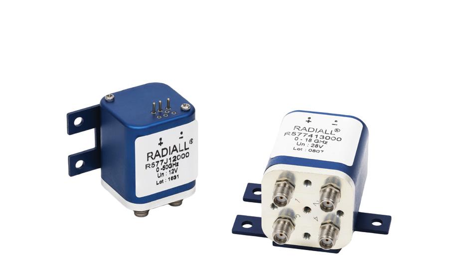
PART NUMBER SELECTION
SERIES PREFIX
RF CONNECTORS
3: SMA up to 6 GHz
4: SMA up to 20 GHz
F: SMA up to 26 5 GHz
8: SMA 2 9 up to 40 GHz [5]
9: DIN 1.6/5.6 up to 2.5 GHz
J: 2 � 4 mm up to 50 GHz
TYPE
1: Failsafe
2: Failsafe + I C
3: Latching
4: Latching + I C
5: Latching + S C O [1]
6: Latching + S �C �O� + I �C � [1]
ACTUATOR VOLTAGE
2: 12 Vdc
3: 28 Vdc

Radiall's DPDT switches offer excellent reliability, high performance and operating frequencies from DC to 50 GHz. Radiall's RAMSES concept guarantees a life span of 2 5 million cycles and provides a full array of options to respond to the needs of our customers
These relays are well suited for applications across all markets including: Defense, Instrumentation, and Telecom.
Example of P/N: R577F63105 is a DPDT SMA 26.5 GHz latching with Indicators, Self Cut-Off, 28 Vdc, TTL driver, D-Sub connector.
R577
ACTUATOR TERMINALS & FIXING
0: Solder pins with bracket
2: Solder pins without bracket
5: D-Sub connector with bracket
7: D-Sub connector without bracket
OPTIONS
0: Without option
1: Positive common [2 & 3]
3: With suppression diodes [1]
4: With suppression diodes and positive common [2 & 3]
TTL OPTION
0: Without TTL driver
1: With TTL driver [1 & 2]
Notes
I.C.: Indicator contact/S.C.O.: Self Cut-Off.
1. Suppression diodes are already included in self cut-off & TTL option.
2. Polarity is not relevant to application for switches with TTL driver.
3. Positive common shall be specified only with type 3,4,5 and 6 because failsafe switches can be used with both polarities.

4. The QLF tradermark (Quick Lock Formula®) standard applies to QMA and QN series and guaranties the full intermateability between suppliers using this tradermark. Using QLF certified connectors also guarantees the specified level of RF performance.
5. Connector SMA 2.9 is equivalent to "K connector ®", registered trademark of Anritsu.
4-2 | DPDT SIMPLIFICATION IS OUR INNOVATION Visit www.radiall.com for more information
GENERAL SPECIFICATIONS
See Power Rating Chart page 1-13
(max)
Actuator terminals
Solder pins or male 9 pin D-Sub connector
Operating temperature range DIN 1.6/5.6 –2 4 mm -25ºC to +70ºC
SMA - SMA 2 9 - QMA -40ºC to +85ºC
DIN 1.6/5.6 –2 4 mm -40ºC to +85ºC
Storage temperature range
SMA - SMA 2 9 - QMA -55ºC to +85ºC
Vibration (MIL STD 202, Method 204D, Cond. C) 10-2,000 Hz, 10g operating Shock (MIL STD 202, Method 213B, Cond. G) 50 g/11 ms, ½ sine operating
RF PERFORMANCE
DPDT | 4-3 SIMPLIFICATION IS OUR INNOVATION Visit www.radiall.com for more information
CONNECTORS FREQUENCY RANGE GH z V.S.W.R. (MAX) INSERTION LOSS (MAX) dB ISOLATION (MIN) dB IMPEDANCE Ω DIN 1.6/5/6 DC - 2.5 DC - 1 1 20 0 20 80 75 1 - 25 1� 30 0� 30 70 QMA DC - 6 DC - 3 1 20 0 20 80 50 3 - 6 1 20 0 30 70 SMA DC - 3 DC - 18 DC - 26.5 DC - 3 1� 20 0� 20 80 50 3 - 8 1 30 0 30 70 8 - 12 4 1 40 0 40 65 12 4 - 18 1 50 0 50 60 18 - 26 5 1 70 0 70 50 SMA 2 9 DC - 40 DC - 6 1 30 0 30 70 50 6 - 12 4 1 40 0 40 60 12 4 - 18 1 50 0 50 60 18 - 26 � 5 1�70 0�70 55 26 5 - 40 1 90 0 80 50 2 4 mm DC - 50 DC - 6 1 30 0 30 70 50 6 - 12 � 4 1� 40 0� 40 60 12 4 - 18 1 50 0 50 60 18 - 26 5 1 70 0 70 55 26 5 - 40 1 90 0 80 50 40 - 50 2 00 1 10 50
OPERATING MODE FAILSAFE LATCHING Nominal operating voltage (across operating temperature) Vdc 12 (10 2 / 13) 28 (24 / 30) 12 (10 2 / 13) 28 (24 / 30) Coil resistance (+/-10%) Ω 35 200 38 225 Nominal operating current at 23 °C mA 340 140 320 125
power
TTL input High Level 2 2 to 5 5 Volts - 800 µA max 5 5 Volts Low Level 0 to 0� 8 Volts - 20 µA max 0 � 8 Volts
1 W/30
mA
SMA - SMA 2.9
QMA
DIN 1.6/5.6
mm
Average
Indicator rating
V/100
Switching time
ms 15 Life SMA - SMA 2 �9 - QMADIN 1.6/5.6 2 � 5 million cycles 2 4 mm 2 million cycles Connectors
-
-
– 2.4
RAMSES Series
See page 4-4 for typical RF performance.
R577 TYPICAL RF PERFORMANCE
Example: DPDT SMA up to 26.5 GHz
INSERTION LOSS & ISOLATION
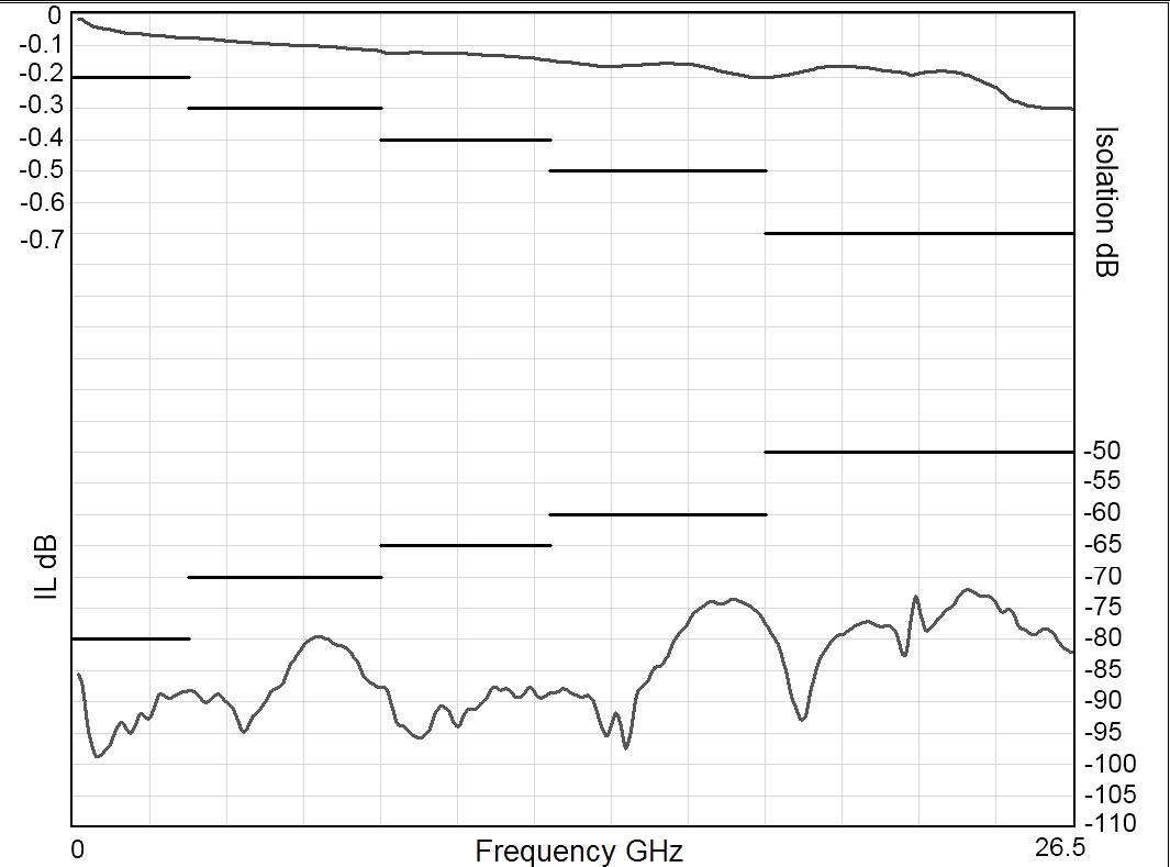
Frequency (GHz)
Example: DPDT SMA 2.9 up to 40 GHz
INSERTION LOSS & ISOLATION
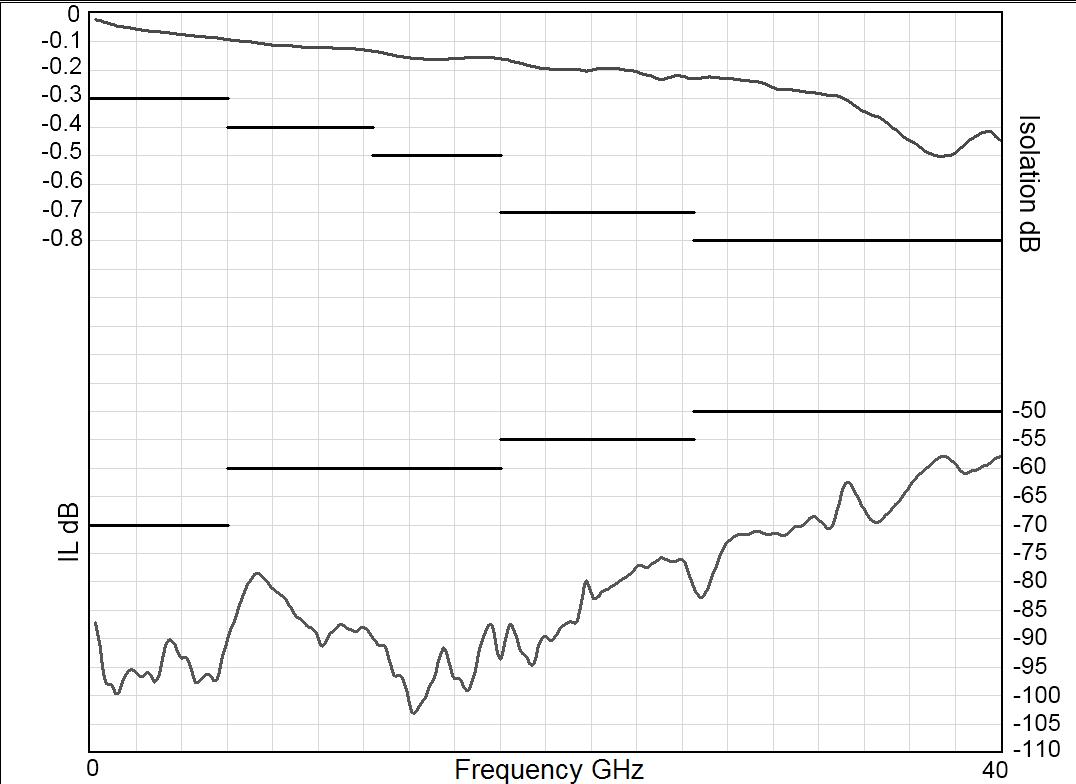
Frequency (GHz)
Example: DPDT 2.4 mm up to 50 GHz
INSERTION LOSS & ISOLATION
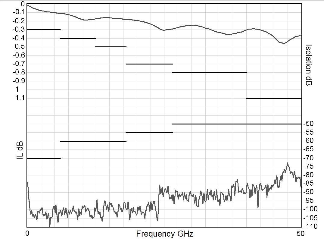
V.S.W.R
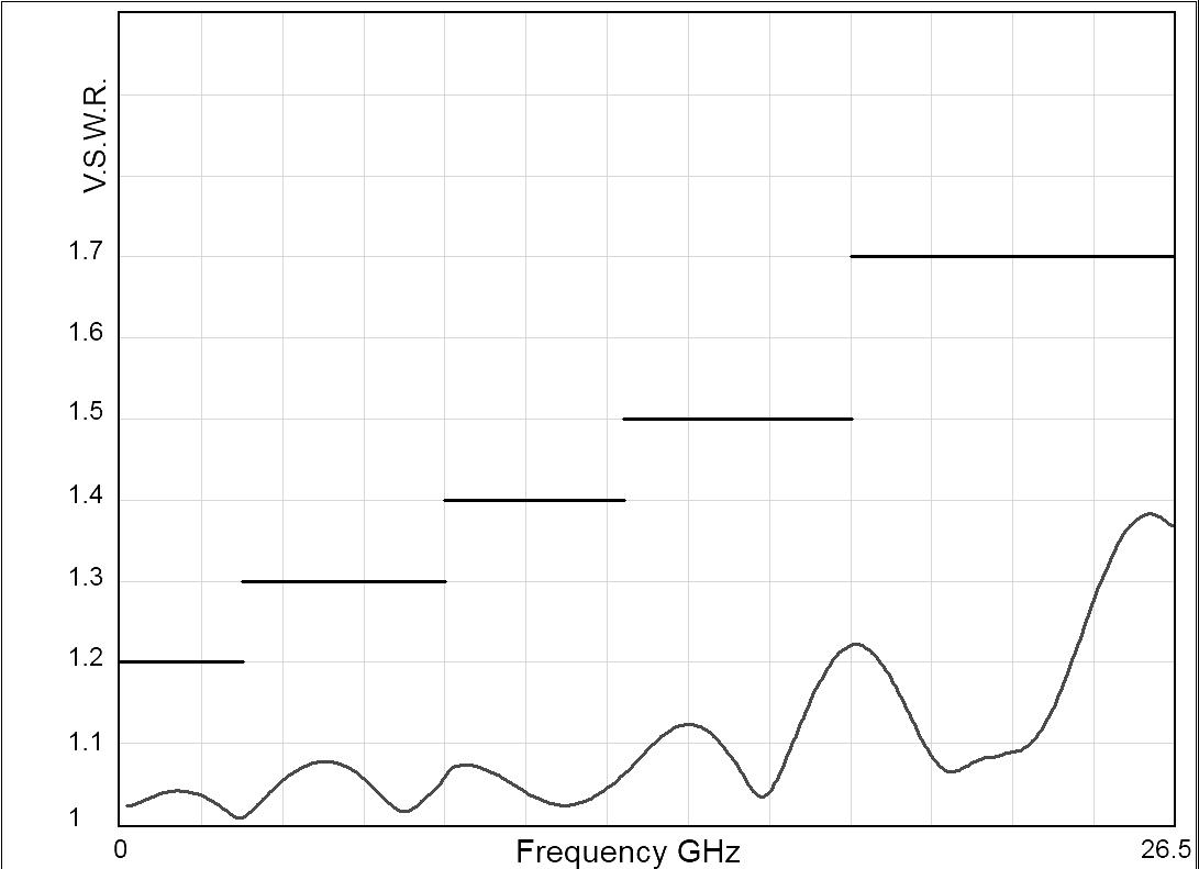
V.S.W.R
V.S.W.R
Frequency (GHz)
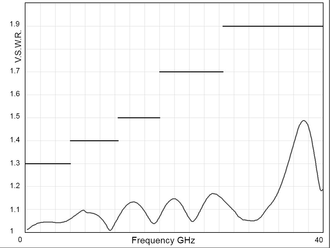
Frequency (GHz)
Frequency (GHz) RAMSES Series
Frequency (GHz)
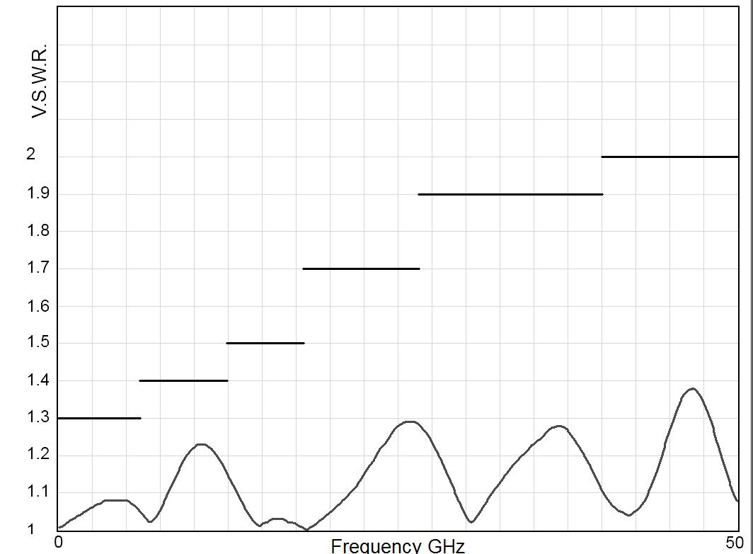
4-4 | DPDT SIMPLIFICATION IS OUR INNOVATION Visit www.radiall.com for more information
RAMSES Series
TYPICAL OUTLINE DRAWING
WITH SOLDER PINS & BRACKET
WITH D-SUB CONNECTOR & BRACKET
ACCESSORIES
A printed circuit board interface connector (ordered separately) has been designed for easy mounting on terminals For DPDT model R577 series = Radiall part number: R599 910 000
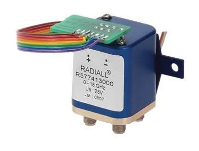
Notes
All dimensions are in millimeters [inches]. PCB accessory pin number assignment is independant from the pin identification table of the switch.
DPDT | 4-5 SIMPLIFICATION IS OUR INNOVATION Visit www.radiall.com for more information
CONNECTORS SMA SMA 2.9 & 2.4 MM QMA DIN 1.6/5.6 A max (mm [inches]) 7 7 [0 303] 6 7 [0 264] 10 8 [0 394] 11 5 [0 433]
RAMSES Series
DPDT UP TO 12.4 GHz - RAMSES Concept
N - BNC - TNC
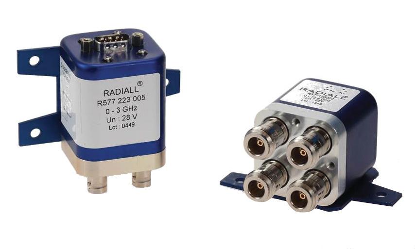
PART NUMBER SELECTION
SERIES PREFIX
RF CONNECTORS
0: N up to 3 GHz
1: N up to 12 4 GHz
2: BNC up to 3 GHz
5: TNC up to 3 GHz
6: TNC up to 12 4 GHz
TYPE
1: Failsafe
2: Failsafe + I C
3: Latching
4: Latching + I �C �
5: Latching + S �C �O� [1]
6: Latching + S C O + I C [1]
ACTUATOR VOLTAGE
2: 12 Vdc
3: 28 Vdc
TTL OPTION
0: Without TTL driver
1: With TTL driver [1 & 2]
OPTIONS
0: Without option
1: Positive common [2 & 3]
3: With suppression diodes [1]
Radiall's DPDT switches offer excellent reliability, high performance and operating frequencies from DC to 12.4 GHz. Radiall's RAMSES concept guarantees a life span of 2 5 million cycles and provides a full array of options to respond to the needs of our customers
These relays are well suited for applications across all markets including: Defense, Instrumentation, and Telecom.
Example of P/N: R577122030 is a DPDT N 12.4 GHz, failsafe with Indicators, 12 Vdc, suppression diodes, solder pins with bracket.
R577
4: With suppression diodes and positive common [2 & 3]
ACTUATOR TERMINALS & FIXING
0: Solder pins with bracket
2: Solder pins without bracket
5: D-Sub connector with bracket
7: D-Sub connector without bracket
Notes
I.C.: Indicator contact/S.C.O.: Self Cut-Off.
1. Suppression diodes are already included in self cut-off & TTL option.
2. Polarity is not relevant to application for switches with TTL driver.
3. Positive common shall be specified only with type 3,4,5 and 6 because failsafe switches can be used with both polarities.
4-6 | DPDT SIMPLIFICATION IS OUR INNOVATION Visit www.radiall.com for more information
GENERAL SPECIFICATIONS OPERATING MODE
Average power
Indicator rating
Power Rating Chart page 1-13
Switching time (max) ms 15 Life 2 � 5 million cycles
Connectors N - BNC - TNC
Actuator terminals Solder pins or male 9 pin D-Sub connector
Operating temperature range -40ºC to +85ºC
Storage temperature range -55ºC to +85ºC
Vibration (MIL STD 202, Method 204D, cond. C)
Shock (MIL STD 202, Method 213B, cond. G)
RF PERFORMANCE
CONNECTORS
See page 4-8 for typical RF performance.
DPDT | 4-7 SIMPLIFICATION IS OUR INNOVATION Visit www.radiall.com for more information
FAILSAFE LATCHING Nominal operating
Vdc 12 (10 2 / 13) 28 (24 / 30) 12 (10 2 / 13) 28 (24 / 30) Coil resistance (+/-10%) Ω 35 200 38 225 Nominal operating current at 23ºC mA 340 140 320 125
voltage (across operating temperature)
TTL input High Level 2 2 to 5 5 Volts Low Level 0 to 0 8 Volts
See
1 W / 30 V / 100 mA
10 -
operating
50 g / 11 ms, ½ sine operating
2,000 Hz, 10g
RANGE GH z V.S.W.R. (MAX) INSERTION LOSS (MAX) dB ISOLATION (MIN) dB IMPEDANCE Ω BNC DC - 3 DC - 1 1�15 0�15 85 50 1 - 2 1 20 0 20 80 2 - 3 1 25 0 25 75 N - TNC DC - 3 DC - 12.4 DC - 1 1 15 0 15 85 1 - 2 1 20 0 20 80 2 - 3 1� 25 0� 25 75 3 - 8 1 35 0 35 70 8 - 12 4 1 50 0 50 60 RAMSES Series
FREQUENCY
R577 TYPICAL RF PERFORMANCE
Example: DPDT N/TNC up to 12.4 GHz
INSERTION LOSS & ISOLATION
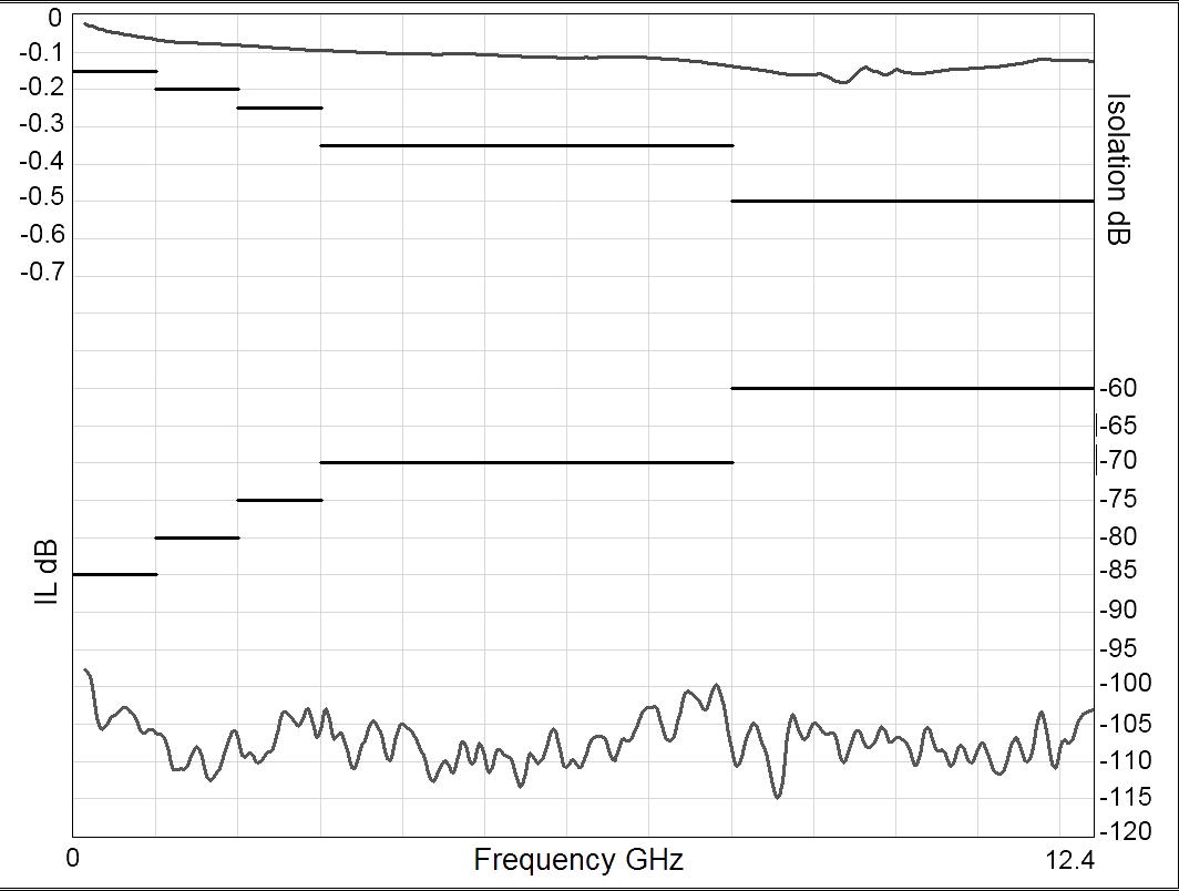
Frequency (GHz)
Example: DPDT BNC up to 3 GHz
INSERTION LOSS & ISOLATION
V.S.W.R
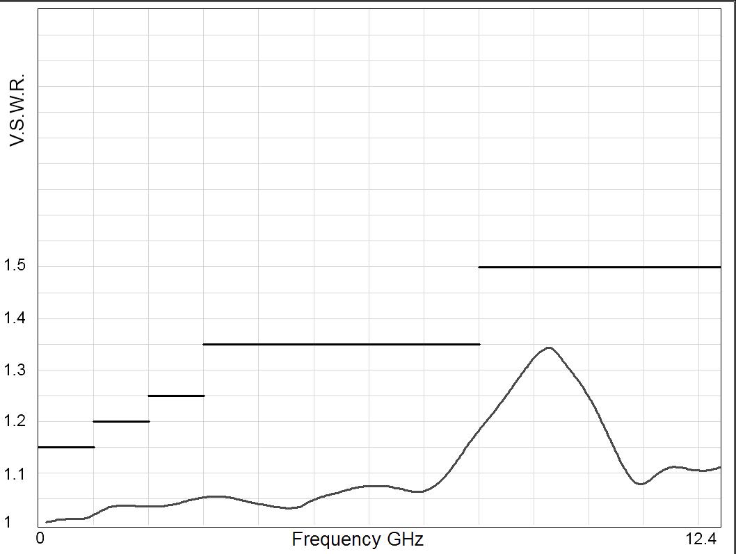
V.S.W.R
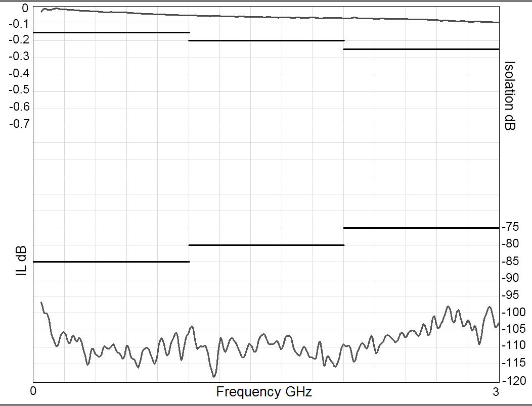
Frequency (GHz)
Frequency (GHz)
Frequency (GHz) RAMSES
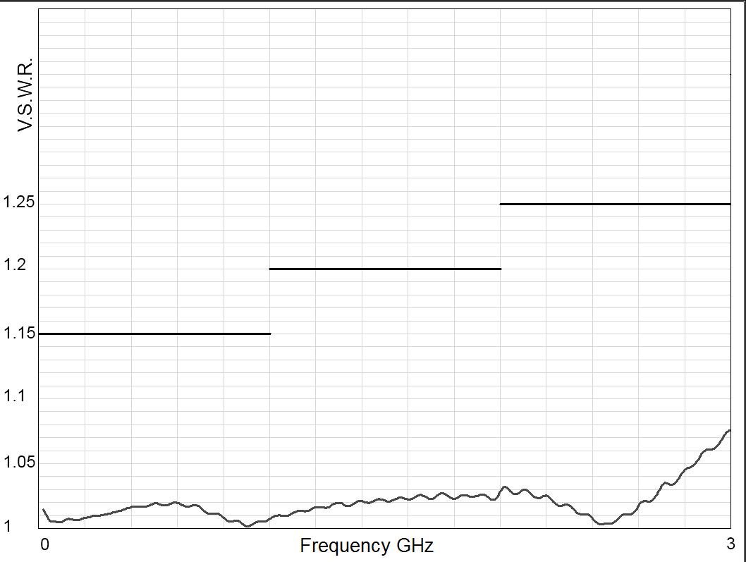
4-8 | DPDT SIMPLIFICATION IS OUR INNOVATION Visit www.radiall.com for more information
Series
RAMSES Series
TYPICAL OUTLINE DRAWING
WITH SOLDER PINS & BRACKET
WITH D-SUB CONNECTOR & BRACKET
ACCESSORIES
A printed circuit board interface connector (ordered separately) has been designed for easy mounting on terminals For DPDT model R577 series = Radiall part number: R599 910 000
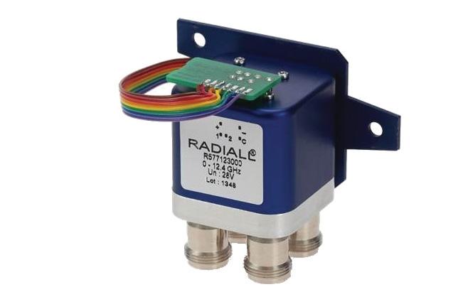
Notes
All dimensions are in millimeters [inches]. See page 4-13 for pin allocation.
DPDT | 4-9 SIMPLIFICATION IS OUR INNOVATION Visit www.radiall.com for more information
CONNECTORS N BNC TNC A max (mm [inches]) 19 5 [0 748] 12 5 [0 472] 12 5 [0 472]
Electrical Schematics
COAXIAL DPDT
R577 SERIES
FAILSAFE
WITHOUT OPTION
R577-1-000
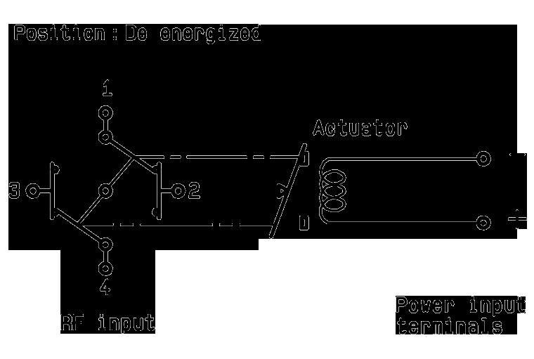
WITH SUPPRESSION DIODES
R577-1-030
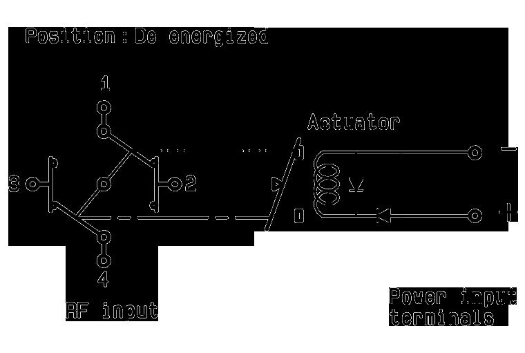
WITH TTL DRIVER (SUPPRESSION DIODES ARE INCLUDED)
R577-1-100
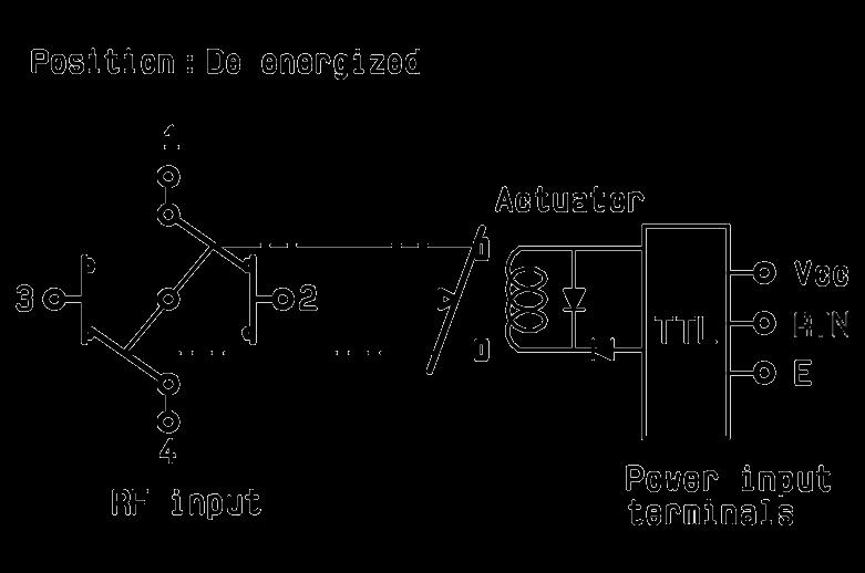
WITH INDICATOR CONTACT
R577-2-000
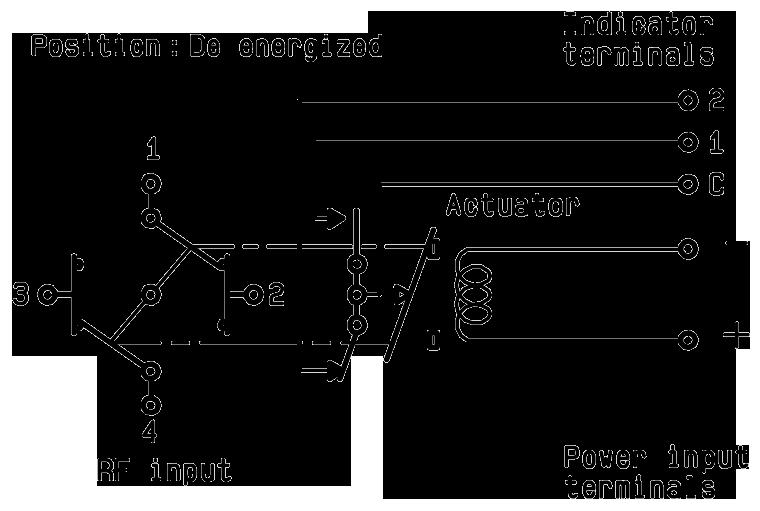
WITH SUPPRESSION DIODES & INDICATOR CONTACT
R577-2-030
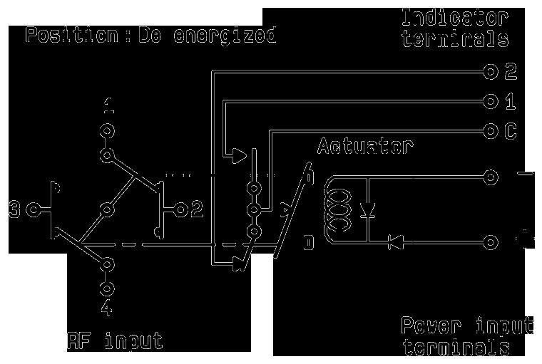
WITH TTL DRIVER & INDICATOR CONTACT (SUPPRESSION DIODES ARE INCLUDED)
R577-2-100
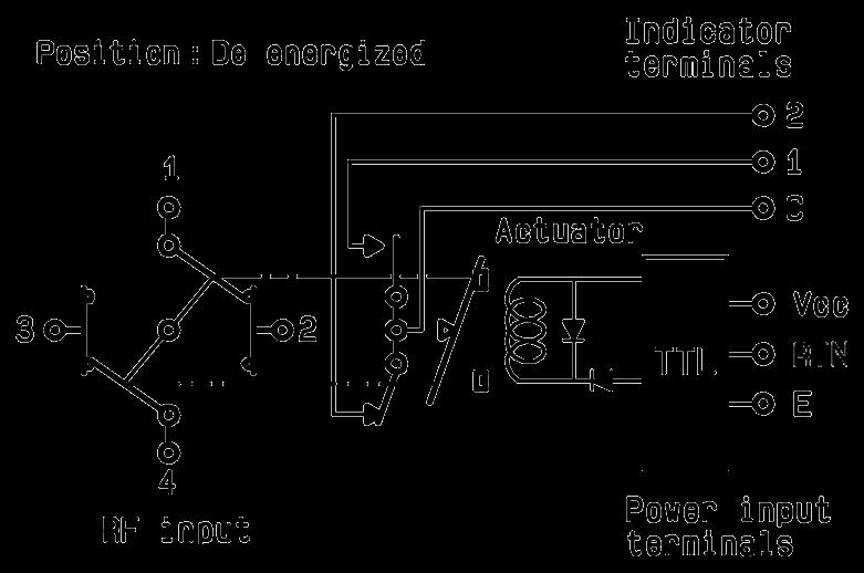
4-10 | DPDT SIMPLIFICATION IS OUR INNOVATION Visit www.radiall.com for more information
Electrical Schematics
COAXIAL DPDT
R577 SERIES
LATCHING
WITHOUT OPTION
R577-3-000
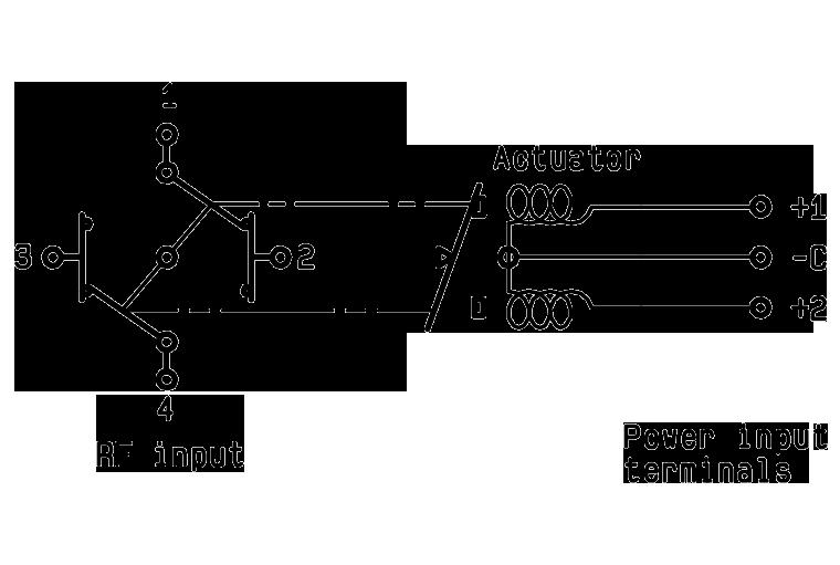
WITH SUPPRESSION DIODES
R577-3-030
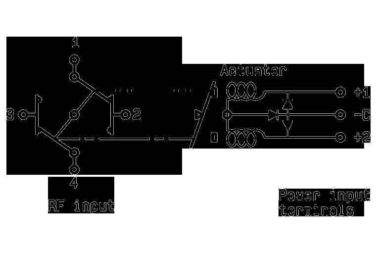
WITH TTL DRIVER (SUPPRESSION DIODES ARE INCLUDED)
R577-3-100
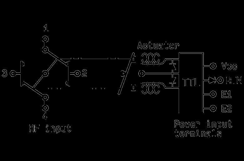
WITH INDICATOR CONTACT
R577-4-000

WITH SUPPRESSION DIODES & INDICATOR CONTACT
R577-4-030
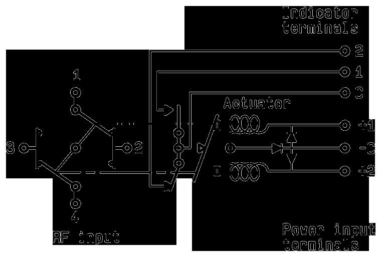
WITH TTL DRIVER & INDICATOR CONTACT (SUPPRESSION DIODES ARE INCLUDED)
R577-4-100
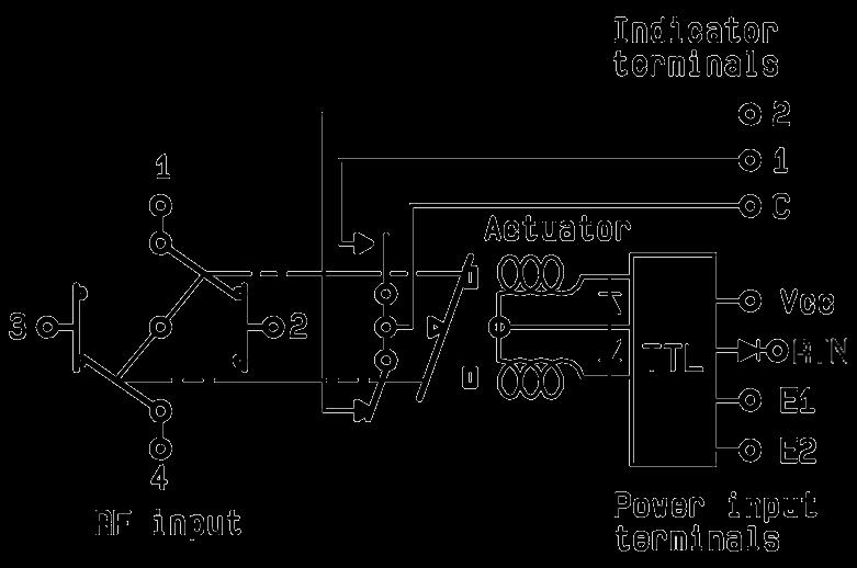
DPDT | 4-11 SIMPLIFICATION IS OUR INNOVATION Visit www.radiall.com for more information
Electrical Schematics
COAXIAL DPDT (CONTINUED)
R577 SERIES
LATCHING
WITH CUT-OFF (SUPPRESSION DIODES ARE INCLUDED)
R577-5-000
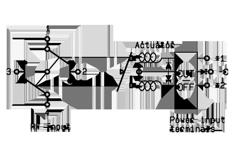
WITH CUT-OFF & TTL DRIVER
R577-5-100
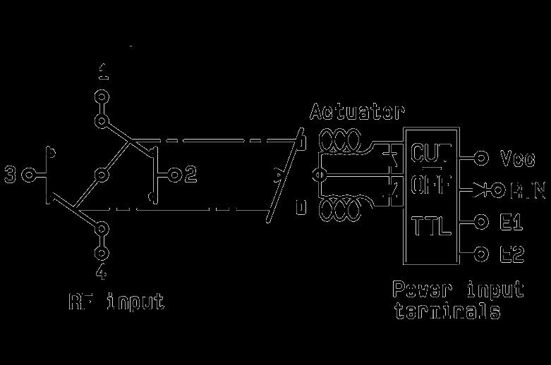
WITH POSITIVE COMMON, NO OPTION
R577-3-010

WITH CUT-OFF & INDICATOR CONTACT (SUPPRESSION DIODES ARE INCLUDED)
R577-6-000
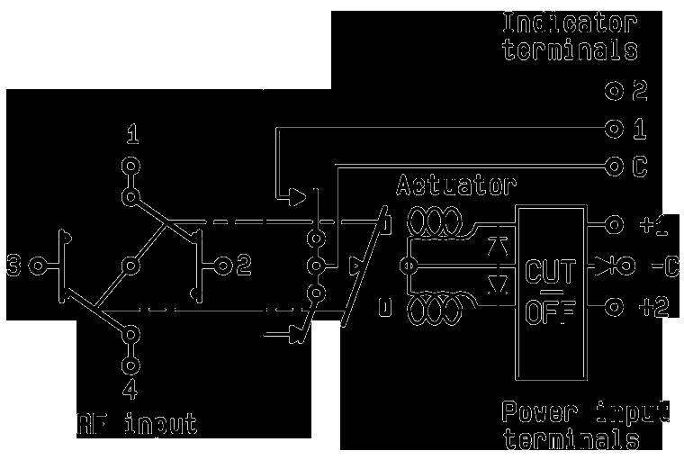
WITH CUT-OFF & INDICATOR CONTACT (SUPPRESSION DIODES ARE INCLUDED)
R577-6-100
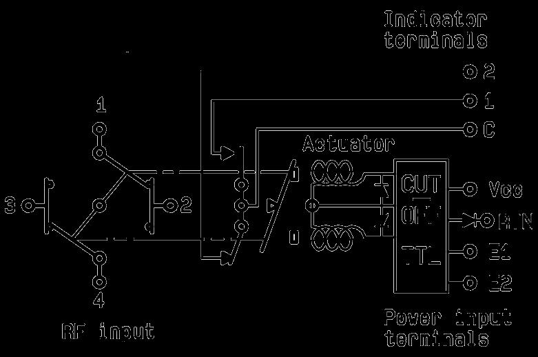
WITH POSITIVE COMMON & INDICATOR CONTACT
R577-4-010

4-12 | DPDT SIMPLIFICATION IS OUR INNOVATION Visit www.radiall.com for more information
Electrical Schematics
COAXIAL DPDT (CONTINUED)
R577 SERIES
LATCHING
WITH POSITIVE COMMON & SUPPRESSION DIODES
R577-3-040
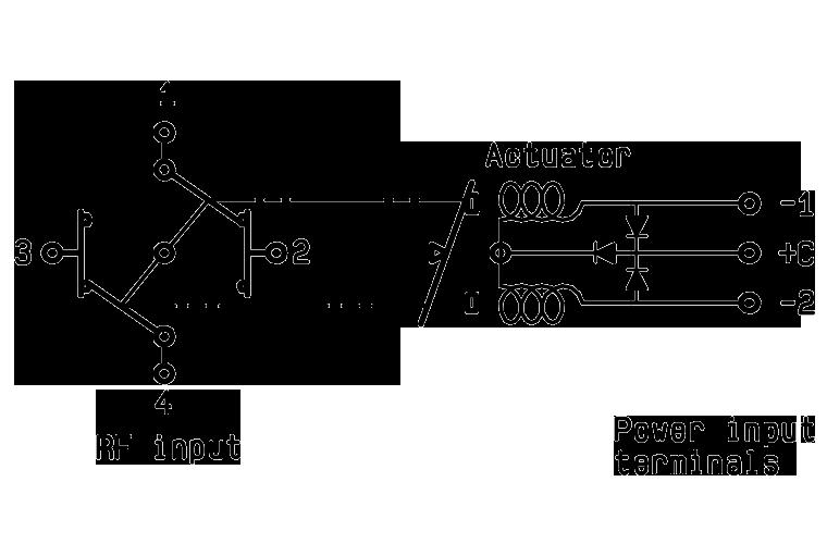
WITH POSITIVE COMMON & CUT-OFF (SUPPRESSION DIODES ARE INCLUDED)
R577-5-010
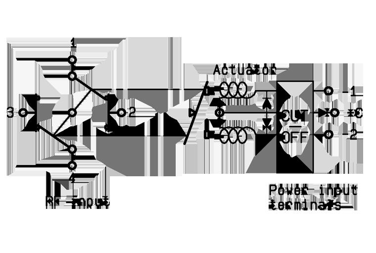
PIN IDENTIFICATION
WITH POSITIVE COMMON, SUPPRESSION DIODES & INDICATOR CONTACT
R577-4-040
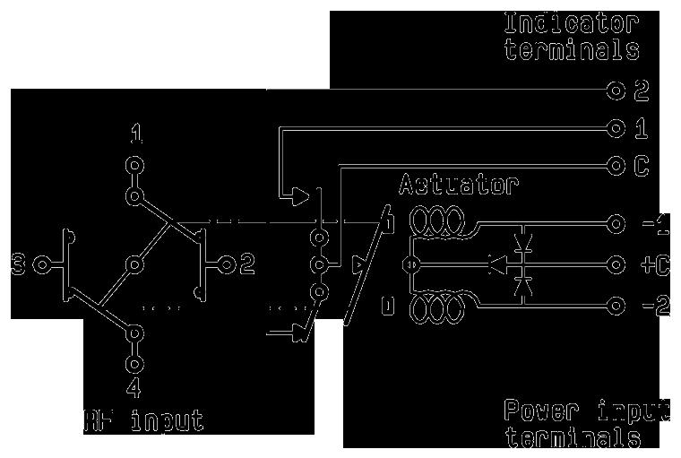
WITH POSITIVE COMMON, CUT-OFF & INDICATOR CONTACT (SUPPRESSION DIODES ARE INCLUDED)
R577-6-010
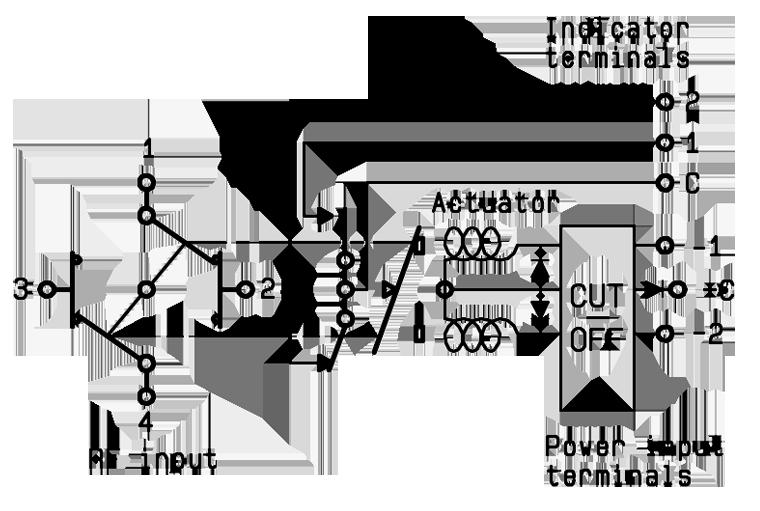
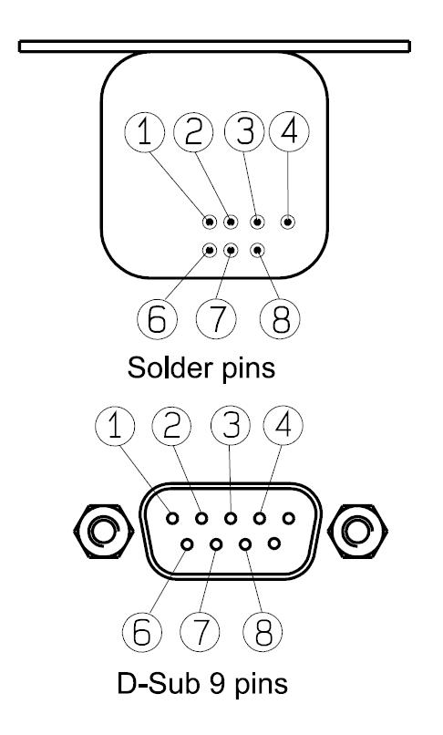
DPDT | 4-13 SIMPLIFICATION IS OUR INNOVATION Visit www.radiall.com for more information
TYPE PIN 1 2 3 4 6 7 8 Failsafe + –Failsafe + I C + – 1 2 C Failsafe + TTL E RTN VCC Failsafe + I C + TTL E RTN VCC 1 2 C
+ Cut-off -1 or +1 -2 or +2 +C or -C Latching + I �C �
+ I.C. + Cut-off -1 or +1 -2 or +2 +C or -C 1 2 C
E2 E1 RTN VCC Latching
TTL + I C E2 E1 RTN VCC 1 2 C
Latching Latching
Latching
Latching + Cut-off Latching + Cut-off + I.C.
+
Top View
Titanium Series
HIGH PERFORMANCE DPDT
DPDT UP TO 40 GHz
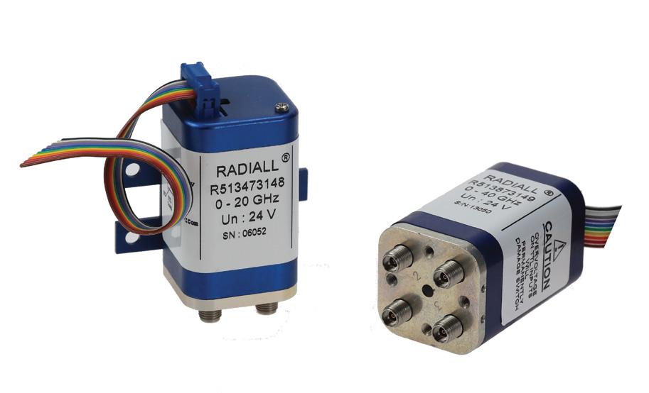
PART NUMBER SELECTION
SERIES PREFIX
RF CONNECTORS
3: SMA up to 6 GHz
4: SMA up to 20 GHz
F: SMA up to 26 5 GHz
8: SMA2 9 up to 40 GHz [2]
TYPE
7: Latching + Self cut-off + Indicators
ACTUATOR VOLTAGE
3: 24 Vdc
TTL OPTION
1: With TTL driver
OPTIONS
4: With suppression diodes and positive common
ACTUATOR TERMINALS & FIXING
8: HE 10 receptacle with bracket [1]
9: HE 10 receptacle without bracket [1]
DOCUMENTATION
-: Certificate of conformity
C: Calibration certificate
R: Calibration certificate + RF curves
Radiall’s TITANIUM series switches are optimized to perform at a high level over an extended life cycle. With outstanding RF performance, and a guaranteed insertion loss repeatability of 0 03 dB over a life span of 2 5 million switching cycles Radiall's TITANIUM switches are perfect for automated test and measurement equipment, as well as signal monitoring devices �
Example of P/N: R513473148 is a DPDT SMA 20 GHz, latching, Self Cut-Off, diodes, positive common, TTL driver, Indicators, HE10 receptacle with bracket.
R513
Notes
1. Delivered wIth 750 mm (30 inches) ribbon cable + HE10 connector.
2. Connector SMA2.9 is equivalent to "K connector ®" registered trademark of Anritsu.
4-14 | DPDT SIMPLIFICATION IS OUR INNOVATION Visit www.radiall.com for more information
GENERAL SPECIFICATIONS
OPERATING MODE LATCHING
Nominal operating voltage (across operating temperature) Vdc 24 (20/32)
Coil resistance (+/-10%) Ω
Nominal operating current at 23 °C mA
Maximum stand-by current mA 50
Average power RF path Cold switching: see RF Power Rating Chart on page 4-19
TTL input
Indicator specifications
Hot switching: 1 Watt CW
High Level 3 to 7 V 1 4 mA max at 7 V
Low Level 0 to 0 8 Volts -
Maximum withstanding voltage 60 V
Maximum current capacity 150 mA
Maximum “ON” resistance 2.5 Ω
Minimum “OFF” resistance 100 MΩ
Switching time (max) ms 15
Life (min) 2 5 million cycles
Connectors SMA - SMA 2 �9
Actuator terminals HE10 ribbon receptacle
Weight (Max) g 110
ENVIRONMENTAL SPECIFICATIONS
Operating temperature range
-25ºC to +75ºC
Storage temperature range -55ºC to +85ºC
Temperature cycling (MIL-STD-202, Method 107D, Cond.A)
Vibration (MIL STD 202, Method 204D, Cond.D) operating
Shock (MIL STD 202, Method 213B, Cond.C) operating
Moisture resistance (MIL STD 202, Method 106E, Cond.E)
Altitude storage (MIL STD 202, Method 105C, Cond.B)
-55ºC to +85ºC (10 cycles)
10 - 2,000 Hz, 10 g
50 g / 6 ms, 1/2 sine
65ºC, 95% RH, 10 days
50,000 ft (15,240 meters)
RFI (MIL STD 1344, Method 3008 or IEC 61726) 40 dB at 20 GHz
DPDT | 4-15 SIMPLIFICATION IS OUR INNOVATION Visit www.radiall.com for more information
Titanium Series
120
200
RF PERFORMANCE PART
TYPICAL RF PERFORMANCE
LOSS & ISOLATION
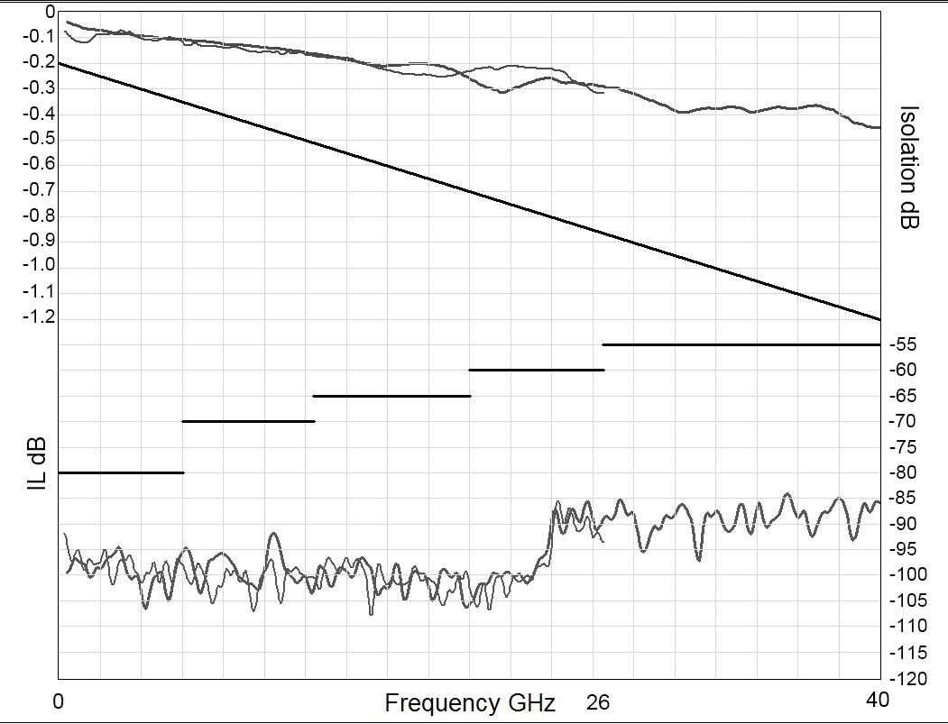
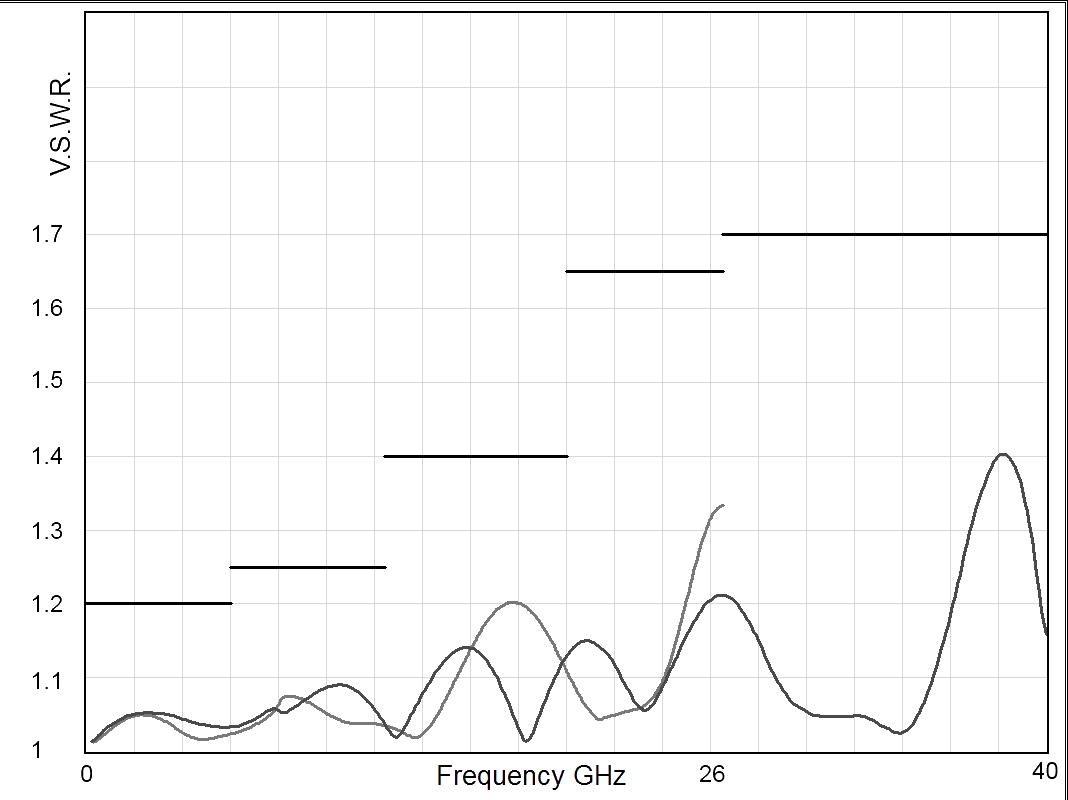
4-16 | DPDT SIMPLIFICATION IS OUR INNOVATION Visit www.radiall.com for more information
Titanium Series
Frequency (GHz) Frequency (GHz)
NUMBER R51337314- R51347314- R513F7314- R51387314Frequency Range GHz DC to 6 DC to 20 DC to 26.5 DC to 40
Ω 50
Loss (max) dB 0.2 + 0.025 × frequency (GHz) Isolation (min) dB 80 DC to 6 GHz 6 to 12 4 GHz 12 4 to 20 GHz 80 70 65 DC to 6 GHz 6 to 12 4 GHz 12 4 to 20 GHz 20 to 26 � 5 GHz 80 70 65 60 DC to 6 GHz 6 to 12 4 GHz 12 4 to 20 GHz 20 to 26 5 GHz 26 � 5 to 40 GHz 80 70 65 60 55 V� S �W� R � (max) 1� 20 DC to 6 GHz 6 to 12 � 4 GHz 12 4 to 20 GHz 1 20 1� 25 1 40 DC to 6 GHz 6 to 12 � 4 GHz 12 4 to 20 GHz 20 to 26 5 GHz 1 20 1� 25 1 40 1 65 DC to 6 GHz 6 to 12 � 4 GHz 12 � 4 to 20 GHz 20 to 26 5 GHz 26 5 to 40 GHz 1 20 1� 25 1� 40 1 65 1 70 Repeatability (at 25 °C) 0 03 dB 0 05 dB
Impedance
Insertion
SMA
SMA
2.9 V.S.W.R INSERTION
DRIVING THE SWITCH
Transfer switches are configured with two positions. Each RF path can be closed by applying ground or TTL "High" to the corresponding "driver " pin�
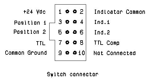
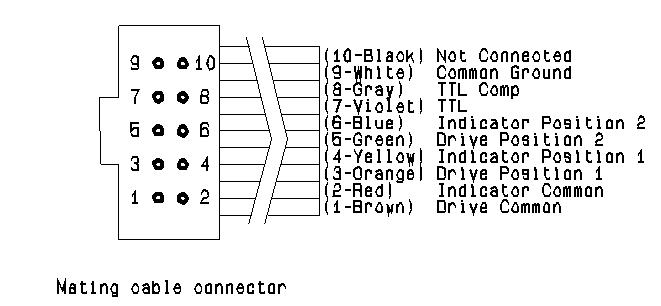
RF SCHEMATIC DIAGRAM
Notes
Position 1 1-2 / 3-4
Position 2 1-3 / 2-4
Standard Drive
• Connect pin 9 to ground (See note)
• Connect pin 1 to supply (+20 VDC to +32 VDC)
• Select (close) desired RF paths by applying ground to the corresponding "drive" pin (Ex: apply ground to pin 3 to close RF path 1-2 and 3-4)
• To select the second path, ensure that the unwanted RF path "drive" pin is disconnected from ground� Apply ground to the "drive" pin which corresponds to the desired RF paths (Ex: apply ground to pin 5 to close RF path 1-3 and 2-4)
TTL Drive (Dual line)
• Connect pin 9 to ground
• Connect pin 1 to supply (+20 VDC to +32 VDC)
• Select (close) desired RF path by applying TTL "High" to the corresponding "drive" pin (Ex: apply TTL "High" to pin 7 and TTL “Low” to pin 8 to close RF paths position 1)
• To select the second path, ensure that the unwanted RF path "drive" pins are in TTL "Low" position Apply TTL "High" to the "drive" pin which correspond to the desired RF path and TTL "low" to the undesired� (Ex: apply TTL "High" to pin 8 and TTL "Low" to pin 7 to close RF paths position 2)
TTL Drive (Single line)
• Connect pin 9 to ground
• Connect pin 1 to supply (+20 VDC to +32 VDC)
• Connect pin 8 to TTL "High"
• Select (close) position 1 by applying TTL "High" to pin 7 (Ex: apply TTL "High" to pin 7 to close RF paths 1-2 and 3-4)
• Select position 2 by applying TTL "Low" to pin 7 (Ex: apply TTL "Low" to pin 7 to close RF paths 1-3 and 2-4)
ICom – I1
ICom – I2
Pin 9 does not need to be grounded for the switch to operate in standard drive. If pin 9 is not grounded, the position indicators will only function while the appropriate drive is applied. Therefore, if a pulse drive is used and continuous indicator operation is required, pin 9 must be grounded.
DPDT | 4-17 SIMPLIFICATION IS OUR INNOVATION Visit www.radiall.com for more information
Titanium Series
GND RF
CONTINUITY INDICATOR
RF PERFORMANCE
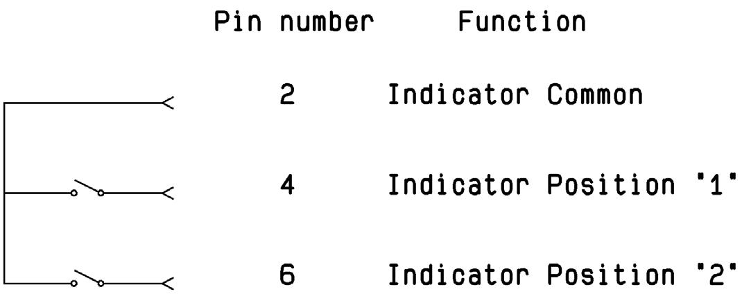
TYPICAL OUTLINE DRAWING
Notes
All dimensions are in millimeters [inches].
The electronic position indicators use photo-MOS transistors, which are driven by the mechanical position of the RF paths moving elements � The circuitry consists of a common which can be connected to an output corresponding to selected RF path The photo-MOS transistors are configured for AC and/or DC operation. The electronic position indicators require the supply (20 to 32 VDC) to be connected to pin 1 and ground connected to pin 9�
4-18 | DPDT SIMPLIFICATION IS OUR INNOVATION Visit www.radiall.com for more information
Titanium Series
SMA SMA 2.9 A max (mm [inches]) 7 7 [0 303] 6 7 [0 264]
CONNECTORS
POWER RATING CHART
This graph is based on the following conditions:
• Ambient temperature: +25 °C
• Sea level
• V.S.W.R.: 1 and cold switching
Average Power Rating (Watts)
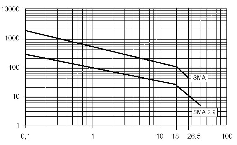
DERATING FACTOR VERSUS V.S.W.R.
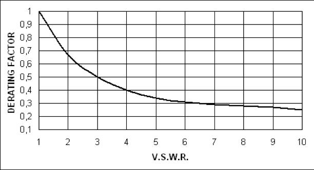
DPDT | 4-19 SIMPLIFICATION IS OUR INNOVATION Visit www.radiall.com for more information
Frequency (GHz)
Titanium Series
Platinum Series
HIGH PERFORMANCE DPDT
DPDT UP TO 40 GHz
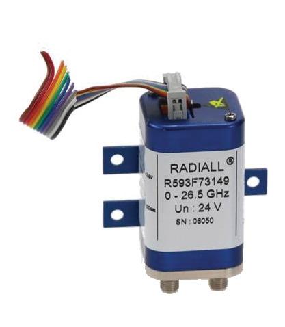
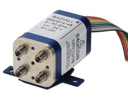
PART NUMBER SELECTION
SERIES PREFIX
RF CONNECTORS
3: SMA up to 6 GHz
4: SMA up to 20 GHz
F: SMA up to 26 5 GHz
8: SMA2 9 up to 40 GHz [2]
TYPE
7: Latching + Self cut-off + Indicators
ACTUATOR VOLTAGE
3: 24 Vdc
TTL OPTION
1: With TTL driver
OPTIONS
4: With suppression diodes and positive common
ACTUATOR TERMINALS AND FIXING
8: HE 10 receptacle with bracket [1]
9: HE 10 receptacle without bracket [1]
DOCUMENTATION
-: Certificate of conformity
C: Calibration certificate
R: Calibration certificate + RF curves
Radiall’s PLATINUM series switches are optimized to perform at a high level over an extended life cycle. With outstanding RF performance, and a guaranteed insertion loss repeatability of 0 03 dB over a life span of 10 million switching cycles PLATINUM series switches are perfect for automated test and measurement equipment, as well as signal monitoring devices �
Example of P/N: R593F73148 is a DPDT SMA 26.5 GHz, latching, Self Cut-Off, diodes, positive common, TTL driver, Indicators, HE10 receptacle with bracket.
Notes
1. Delivered wIth 750 mm (30 inches) ribbon cable + HE10 connector.
2. Connector SMA2.9 is equivalent to "K connector ®" registered trademark of Anritsu.
4-20 | DPDT SIMPLIFICATION IS OUR INNOVATION Visit www.radiall.com for more information
R593
GENERAL SPECIFICATIONS
OPERATING MODE LATCHING
Nominal operating voltage (across operating temperature) Vdc 24 (20/32)
Coil resistance (+/-10%) Ω
Nominal operating current at 23 °C mA 200
Maximum stand-by current mA 50
RF path Cold switching: see RF Power Rating Chart on page 4-25 Hot switching: 1 Watt CW TTl input
Average power
Indicator specifications
High Level 3 to 7 V 1 4 mA max at 7 V
Low Level 0 to 0 8 Volts -
Maximum withstanding voltage
V Maximum current capacity
Maximum “ON” resistance
Ω Minimum “OFF” resistance
Switching time (max) ms 15
- SMA 2 9
Actuator terminals HE10 ribbon receptacle Weight (Max) g 110
ENVIRONMENTAL SPECIFICATIONS
Operating temperature range
-25ºC to +75ºC
Storage temperature range -55ºC to +85ºC
Temperature cycling (MIL-STD-202, Method 107D, Cond.A) -55ºC to +85ºC (10 cycles)
Vibration (MIL STD 202, Method 204D, Cond.D) operating 10 - 2,000 Hz, 10 g
Shock (MIL STD 202, Method 213B, Cond.C) operating 50 g / 6 ms, 1/2 sine
Moisture resistance (MIL STD 202, Method 106E, Cond.E) 65ºC, 95% RH, 10 days
Altitude storage (MIL STD 202, Method 105C, Cond.B) 50,000 ft (15,240 meters)
RFI (MIL STD 1344, Method 3008 or IEC 61726) 40 dB at 20 GHz
MΩ
DPDT | 4-21 SIMPLIFICATION IS OUR INNOVATION Visit www.radiall.com for more information
Platinum Series
120
60
150 mA
100
2.5
life (min) SMA 10 million cycles SMA
2 9 5 million cycles Connectors SMA
RF PERFORMANCE PART
TYPICAL RF PERFORMANCE
INSERTION LOSS & ISOLATION
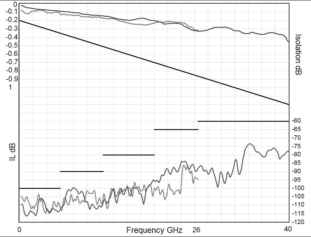
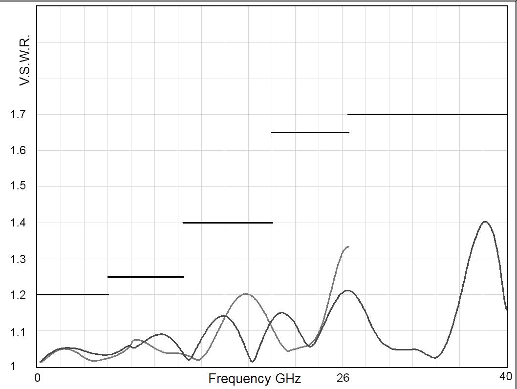
4-22 | DPDT SIMPLIFICATION IS OUR INNOVATION Visit www.radiall.com for more information
Platinum Series
Frequency (GHz) Frequency (GHz)
NUMBER R59337314- R59347314- R593F7314- R59387314- R51387314Frequency Range GHz DC to 6 DC to 20 DC to 26.5 DC to 40 Impedance Ω 50 Insertion Loss (max) dB 0.2 + 0.025 × frequency (GHz) Isolation (min) dB 100 DC to 6 GHz 6 to 12 4 GHz 12 4 to 20 GHz 100 90 80 DC to 6 GHz 6 to 12 4 GHz 12 4 to 20 GHz 20 to 26 � 5 GHz 100 90 80 65 DC to 6 GHz 6 to 12 4 GHz 12 4 to 20 GHz 20 to 26 5 GHz 26 � 5 to 40 GHz 100 90 80 65 60 V� S �W� R � (max) 1� 20 DC to 6 GHz 6 to 12 � 4 GHz 12 4 to 20 GHz 1 20 1� 25 1 40 DC to 6 GHz 6 to 12 � 4 GHz 12 4 to 20 GHz 20 to 26 5 GHz 1 20 1� 25 1 40 1 65 DC to 6 GHz 6 to 12 � 4 GHz 12 � 4 to 20 GHz 20 to 26 5 GHz 26 5 to 40 GHz 1 20 1� 25 1� 40 1 65 1 70 Repeatability (at 25 °C) 0 03 dB 0 05 dB
SMA 2.9
SMA
V.S.W.R
DRIVING THE SWITCH
Transfer switches are configured with two positions. Each RF path can be closed by applying Ground or TTL "High" to the corresponding "driver " pin�
Standard Drive
RF SCHEMATIC DIAGRAM
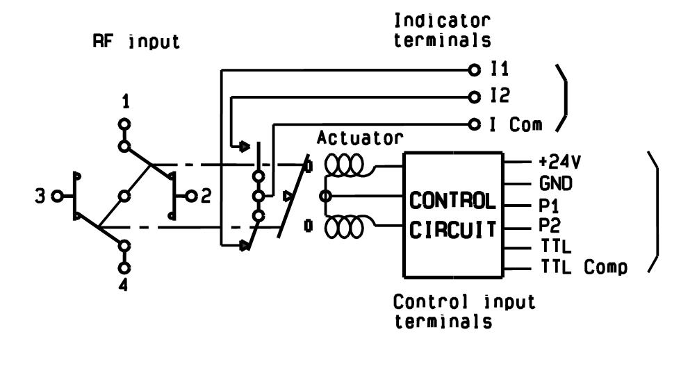
RF CONTINUITY
Position 1 1-2 / 3-4
Position 2 1-3 / 2-4
• Connect pin 9 to ground (See note)
• Connect pin 1 to supply (+20 VDC to +32 VDC)
• Select (close) desired RF paths by applying ground to the corresponding "drive" pin (Ex: apply ground to pin 3 to close RF path 1-2 and 3-4)
• To select the second path, ensure that the unwanted RF path "drive" pin is disconnected from ground� Apply ground to the "drive" pin which corresponds to the desired RF paths (Ex: apply ground to pin 5 to close RF path 1-3 and 2-4)
TTL Drive (Dual line)
• Connect pin 9 to ground
• Connect pin 1 to supply (+20 VDC to +32 VDC).
• Select (close) desired RF path by applying TTL "High" to the corresponding "drive" pin (Ex: apply TTL "High" to pin 7 and TTL “Low” to pin 8 to close RF paths position 1)
• To select the second path, ensure that the unwanted RF path "drive" pins are in TTL "Low" position Apply TTL "High" to the "drive" pin which corresponds to the desired RF path and TTL "low" to the undesired (Ex: apply TTL "High" to pin 8 and TTL "Low" to pin 7 to close RF paths position 2)
TTL Drive (Single line)
• Connect pin 9 to ground
• Connect pin 1 to supply (+20 VDC to +32 VDC)
• Connect pin 8 to TTL "High"
• Select (close) position 1 by applying TTL "High" to pin 7 (Ex: apply TTL "High" to pin 7 to close RF paths 1-2 and 3-4)
• Select position 2 by applying TTL "Low" to pin 7 (Ex: apply TTL "Low" to pin 7 to close RF paths 1-3 and 2-4)
INDICATOR
ICom – I1
ICom – I2
Notes
Pin 9 does not need to be grounded for the switch to operate in standard drive. If pin 9 is not grounded, the position indicators will only function while the appropriate drive is applied. Therefore, if a pulse drive is used and continuous indicator operation is required, pin 9 must be grounded.
DPDT | 4-23 SIMPLIFICATION IS OUR INNOVATION Visit www.radiall.com for more information
Platinum Series
RF PERFORMANCE

TYPICAL OUTLINE DRAWING
Notes
All dimensions are in millimeters [inches].
The electronic position indicators use photo-MOS transistors, which are driven by the mechanical position of the RF paths moving elements � The circuitry consists of a common which can be connected to an output corresponding to selected RF path� The photo-MOS transistors are configured for AC and/or DC operation.
The electronic position indicators require the supply (20 to 32 VDC) to be connected to pin 1 and ground connected to pin 9�
4-24 | DPDT SIMPLIFICATION IS OUR INNOVATION Visit www.radiall.com for more information
Platinum Series
SMA2.9 A max (mm [inches]) 7 7 [0 303] 6 7 [0 264]
CONNECTORS
SMA
POWER RATING CHART
This graph is based on the following conditions:
• Ambient temperature: +25 °C
• Sea level
• V.S.W.R.: 1 and cold switching
Average Power Rating (Watts)
DERATING FACTOR VERSUS V.S.W.R.
DPDT | 4-25 SIMPLIFICATION IS OUR INNOVATION Visit www.radiall.com for more information
Frequency (GHz)
Platinum Series
Optional Features
OPTIONAL FEATURES FOR DPDT SWITCHES
GENERAL
A microwave circuit or component can be inserted into a transmission line by using a DPDT switch as a bypass product. In event that the short-circuit of the microwave circuit or component is undesirable, the J1/J3 path can be left out (see application option below)
EXAMPLES OF DEDICATED APPLICATION OPTIONS
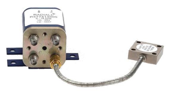
This DPDT with a cable load is used for redundancy purposes for 2 amplifiers, one working, the other one in stand-by�
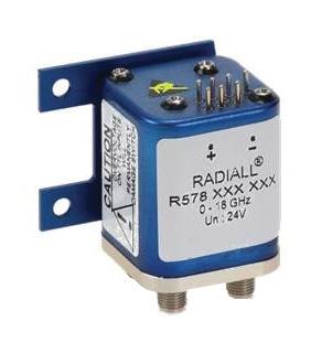
This DPDT has been fitted with a specific bracket to fulfill a specific customer request.
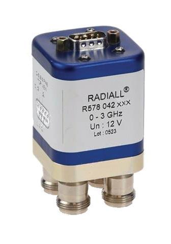
This true Bypass Switch is based on a DPDT with only 3 RF ways instead of 4 �
• Component inserted in J2/J4
• POS 1: J1 to J3: Direct line
• POS 2: J1 to J3: Component line
This DPDT was designed with a specific flat cable for an easy integration
4-26 | DPDT SIMPLIFICATION IS OUR INNOVATION Visit www.radiall.com for more information
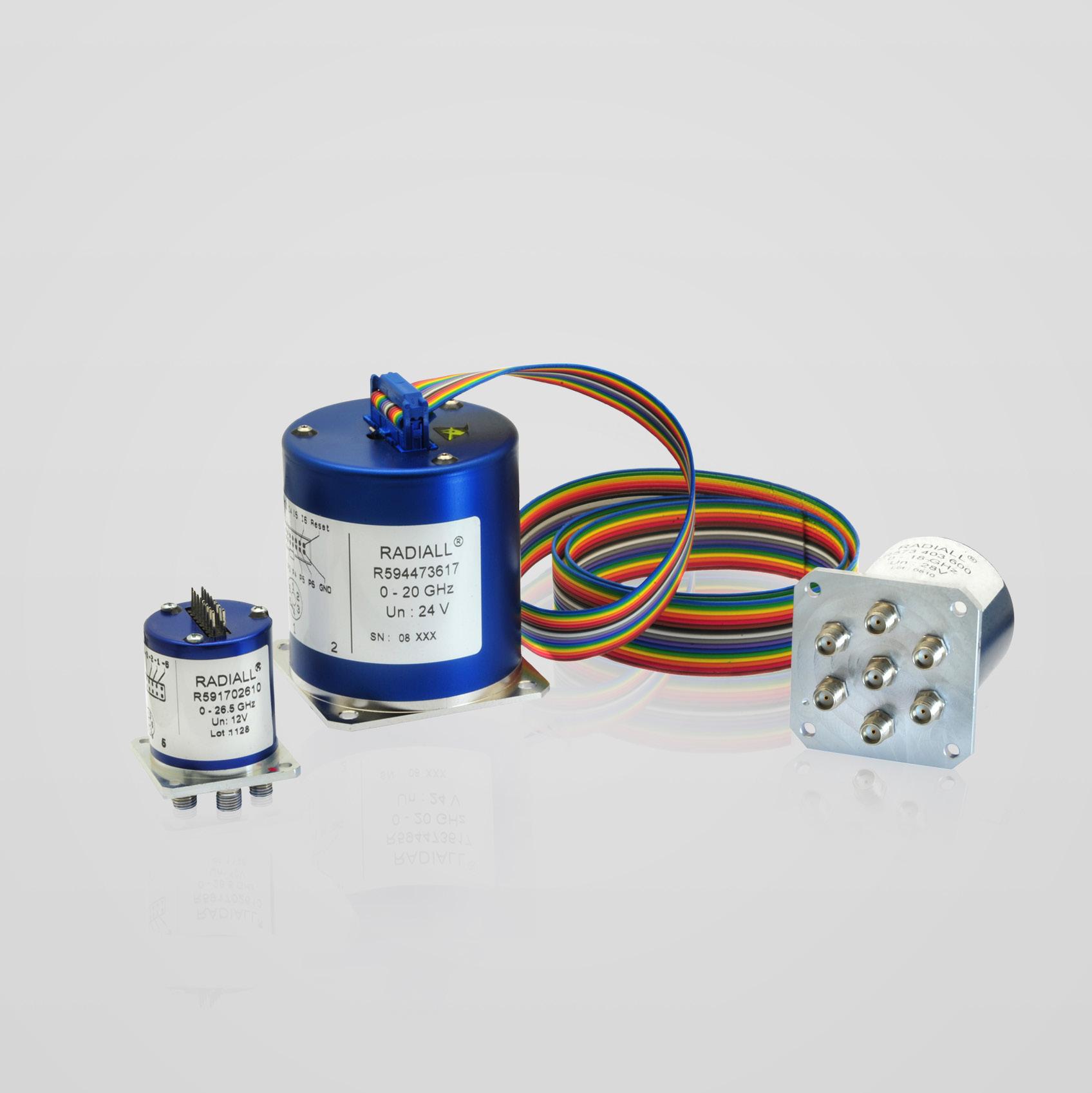
SIMPLIFICATION IS OUR INNOVATION Visit www.radiall.com for more information SECTION 5 SPnT
Section 5 Table of Contents
SUBMINIATURE SERIES
SPnT up to 40 GHz: R591 Series 5-2 to 5-4
R591 Series Electrical Schematics������������������������ 5-5 to 5-7
USB SERIES
SPnT USB up to 40 GHz: R57xxxxx01 Series (Terminated and Non-Terminated) 5-8 to 5-13
RAMSES SERIES
SPnT up to 50 GHz: R57x Series (Terminated and Non-Terminated) ������������������5-14 to 5-25
SPnT up to 12 4 GHz: R57x Series (N, BNC and TNC models)
5-26 to 5-30
RF Connector Allocation for SPnT Series 5-31 to 5-32
SPNT
ACCESSORIES SPNT & ELECTRICAL SCHEMATICS
Coaxial SPnT - Accessories 5-33 to 5-37
Coaxial SPnT - Electrical Schematics��������������� 5-38 to 5-43
TITANIUM SERIES
High Performance Multiport Switches
SPnT up to 40GHz: R51x Series 5-44 to 5-50
PLATINUM SERIES
High Performance Multiport Switches - SPnT Terminated Up to 40 GHz: R594 Series ������������������������������� 5-52 to 5-58
OPTIONAL FEATURES
Optional Features 5-59
Notes
Example of P/N: R591703400 is a SP4T SMA up to 26.5 GHz, normally open, 28 Vdc, without option, solder pins. 1. For part number creation and available options, see detailed part number selection for each series.
driver compatible Solder pins D-Sub connector Mini USB Micro-D connector HE 10 receptacle Certificate of conformity Calibration certificate Calibration certificate + RF curves
SPNT | 5-1 SIMPLIFICATION IS OUR INNOVATION Visit www.radiall.com for more information
��������������������������������
DIGITAL POSITION R 1-3/ MODEL: 4: RF CONNECTORS 5: TYPE 6: VOLTAGE 7: POS. 8: OPTIONS 9: TERMINALS 10: DOCUMENT- ATION Series ConfigurationNot terminated Terminated SMA 3 GHz SMA 6 GHz SMA 18 GHz SMA 20 GHz SMA 26 � 5 GHz SMA 2 � 9 40 GHz 2 � 4mm 50 GHz QMA 6 GHz DIN 1 6/5 6/2 5 GHz N 3 GHz N 12 4 GHz BNC 3 GHz TNC 3 GHz TNC 12 � 4 GHz Normally open Latching 5 V 12 V 24 V 28 V
TTL
SUBMIN � SPnT R591 - - - 3 - - 7 8 - E - - - - - - 0 2/6 - 2 - 3 4/6 0 1 2 3 4 - 0 - - 5 - - -USB SPnT R57 3 4 - - - - F 8 - - - - - - - - 1 - 1 - - - 6/8 0 - - - - - - - 1 - - - -RAMSES SPnT R57 3 4 3 - 4 - F 7/8 J E 9 - - - - - 0/1 2/3/4/5/8/9 - 2 - 3 3-12 0 1 2 3 4 8 0 5 - - - - -R57 3 4 - - - - - - - - - 0 1 2 5 6 0/1 2/3/4/5/8/9 - 2 - 3 3-12 0 1 2 3 4 8 0 5 - - - - -TITANIUM SPnT R51 2 4 - 3 - 4 F 8 - - - - - - - - - 7 - - 3 - 4/6 - 1 2 - - - - - - - 7 - C R PLATINUM SPnT R594 - - - 3 - 4 F 8 - - - - - - - - - 4/7 - - 3 - 4/6 - 1 2 - - - - - - - 7 - C R
PART NUMBER SELECTION GUIDE [1]
Number of positions Without option Positive common TTL driver Suppression diodes Positive common and suppression diodes BCD
Subminiature Series
SUBMINIATURE SPNT UP TO 40 GHz
SMA – SMA 2.9 - QMA
Radiall's R591 coaxial subminiature switches have a typical operating life exceeding 25 million cycles; Providing excellent RF performance, repeatability, and a guaranteed life of 10 million cycles, which makes switches ideal for Automated Test Equipment (ATE) and other measurement applications. These subminiature switches are also an excellent choice for Mil/ Aero applications due to their small size, light weight, and outstanding shock and vibration handling capabilities.
Example of P/N: R591302420 is a SP4T SMA up to 6 GHz, normally open, 12 Vdc with TTL driver and solder pins.
PART NUMBER SELECTION
SERIES PREFIX
RF CONNECTORS
3: SMA up to 6 GHz
7: SMA up to 26 5 GHz
8: SMA 2 9 up to 40 GHz [6]
E: QMA up to 6 GHz [5]
TYPE
0: Normally open
2: Latching, global reset
6: Latching, separated reset [1]
ACTUATOR VOLTAGE
2: 12 Vdc
3: 28 Vdc
NUMBER OF POSITIONS
4: 4 positions
6: 6 positions
OPTIONS
0: Without option
1: Positive common
2: With TTL driver [2, 3 & 4]
3: With suppression diodes
4: With suppression diodes and positive common
ACTUATOR TERMINALS
0: Solder pins
5: Micro-D connector
Notes
1. Available with “solder pins“ models only.
2. Polarity is not relevant to application for switches with TTL driver.
3. Suppression diodes are already included with TTL option.
4. Available with “normally open” models only.
5. The QLF tradermark (Quick Lock Formula®) standard applies to QMA and QN series and guaranties the full intermateability between suppliers using this tradermark. Using QLF certified connectors also guarantees the specified level of RF performance.
6. Connector SMA2.9 is equivalent to "K connector ®", registered trademark of Anritsu.
5-2 | SPNT SIMPLIFICATION IS OUR INNOVATION Visit www.radiall.com for more information
R591
Subminiature Series
GENERAL SPECIFICATIONS
Switching time (max) ms
SMA-QMA 10 million cycles SMA 2 9 2 million cycles
Connectors
Actuator terminals
SMA - QMA - SMA 2 �9
Solder Pins: double row connector for wrapping, soldering (250 ºC max / 30 sec), or connecting to 2.54 mm pitch female connector. 9 pin micro-D receptacle M83513/07-A according to MIL-C-85513.
Operating temperature range -40 ºC to +85 ºC
Storage temperature range -55 ºC to +85 ºC
Sine vibration
(According to MIL STD 202, Method 204D, Cond. D) 10 - 2,000 Hz, 20 g - operating
Random vibration
(According to MIL STD 202, Method 214A, Profile I, Cond. F)
Shock
(According to MIL STD 202, Method 213B, Cond. C)
RF PERFORMANCE
Notes
See page 5-4 for typical RF performance.
50 - 2,000 Hz, 20.71 g - operating
100 g / 6 ms, 1/2 sine - operating
SPNT | 5-3 SIMPLIFICATION IS OUR INNOVATION Visit www.radiall.com for more information
CONNECTORS FREQUENCY RANGE GH z V.S.W.R. (MAX) INSERTION LOSS (MAX) dB ISOLATION (MIN) dB IMPEDANCE Ω QMA / SMA DC - 6 DC - 3 1 20 0 20 80 50 3 - 6 1� 30 0� 30 70 SMA DC - 26-5 DC - 3 1 20 0 20 80 3 - 8 1 30 0 30 70 8 - 12 4 1 40 0 40 60 12 4 - 18 1 50 0 50 60 18 - 26 5 1 60 0 60 55 SMA 2 9 DC - 40 DC - 3 1� 20 0� 20 80 3 - 8 1 30 0 30 70 8 - 12 4 1 40 0 40 60 12 4 - 18 1 50 0 50 60 18 - 26 5 1 70 0 70 55 26 � 5 - 40 2 � 20 1�10 45
OPERATING MODE NORMALLY OPEN LATCHING Nominal operating voltage (across operating temperature) Vdc 12 (10 2 / 13) 28 (21 / 30) 12 (10 2 / 13) 28 (21 / 30) Coil resistance (+/-10%) Ω 48 250 60 285 Operating current at 23 ºC mA 250 110 200 98 Average power See RF Power Rating Chart page 1-13 TTL input High Level 2 2 to 5 5 Volts 800 µA max 5 5 Volts Low Level 0 to 0 8 Volts 20 µA max 0 8 Volts
10 Life
Subminiature Series
TYPICAL RF PERFORMANCE
INSERTION LOSS & ISOLATION
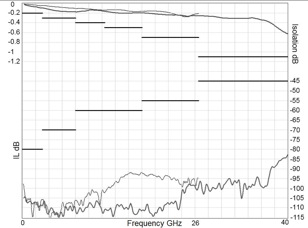
Frequency (GHz)
TYPICAL OUTLINE DRAWING [1]
SOLDER PIN MODEL
Notes
1. For SP4T, ways 3 and 6 not connected
V.S.W.R
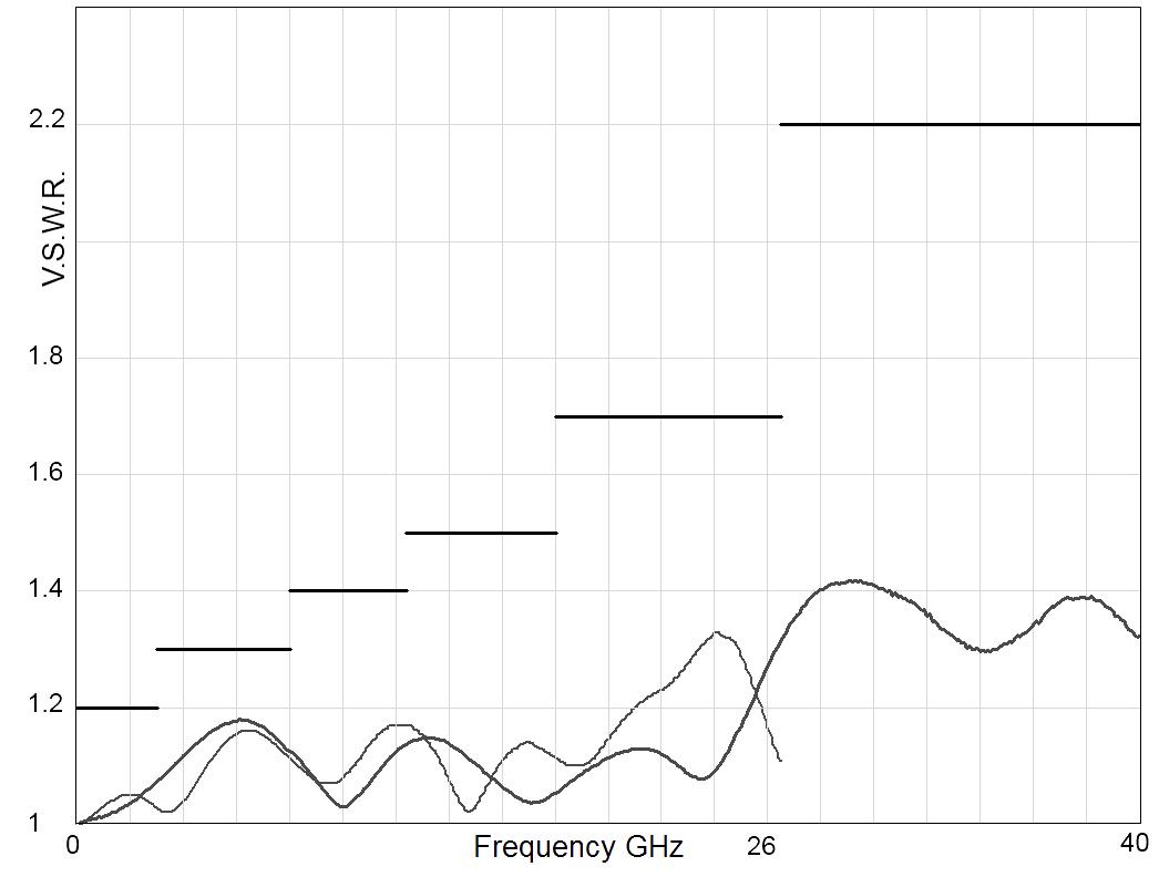
Frequency (GHz)
MICRO-D MODEL
2. All dimensions are in millimeters [inches].
5-4 | SPNT SIMPLIFICATION IS OUR INNOVATION Visit www.radiall.com for more information
CONNECTORS SMA SMA 2.9 QMA A max (mm/ [inches]) 7 7 [0 303] 6 7 [0 264] 10 8 [0 394]
Subminiature Series
R591 SERIES ELECTRICAL SCHEMATICS
NORMALLY OPEN WITHOUT OPTION
R591-0- -0-

NORMALLY OPEN WITH TTL DRIVE
R591-0- -2-
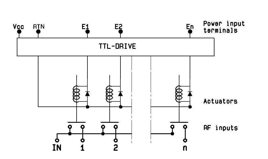
NORMALLY OPEN WITH POSITIVE COMMON & SUPPRESSION DIODES
R591-0- -4-

NORMALLY OPEN WITH POSITIVE COMMON
R591-0- -1-
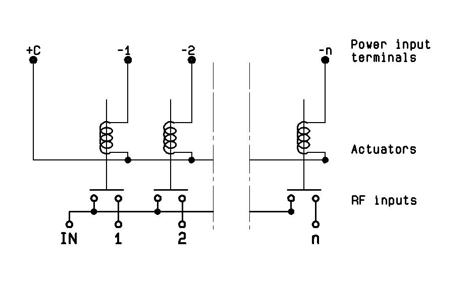
NORMALLY OPEN WITH SUPPRESSION DIODES
R591-0- -3-

LATCHING GLOBAL RESET WITHOUT OPTION
R591-2- -0-
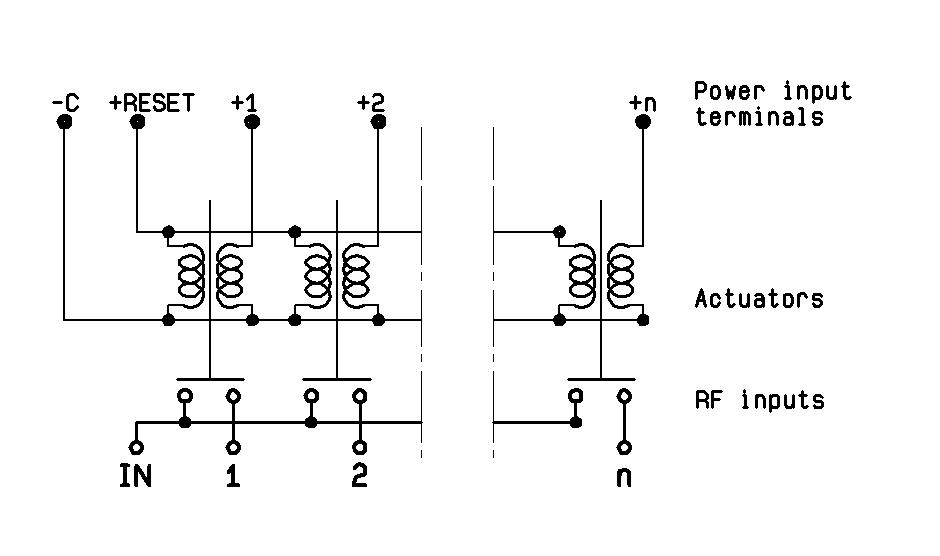
SPNT | 5-5 SIMPLIFICATION IS OUR INNOVATION Visit www.radiall.com for more information
Subminiature Series
LATCHING GLOBAL RESET WITH POSITIVE COMMON
R591-2- -1-
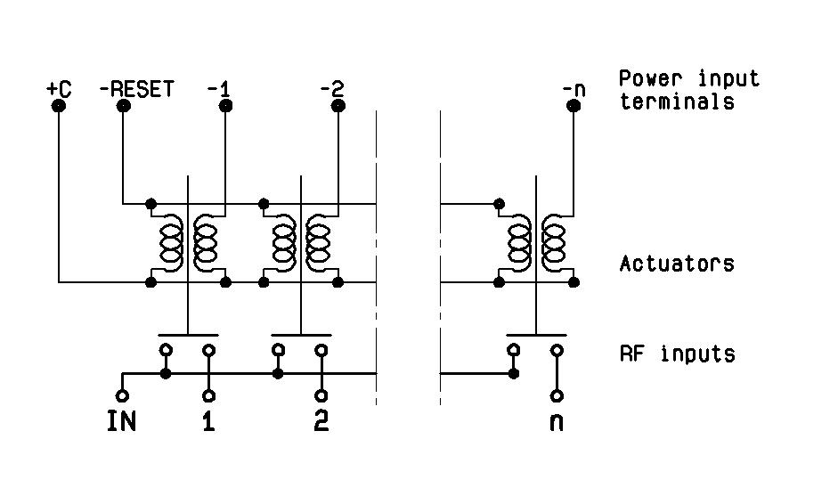
LATCHING GLOBAL RESET WITH POSITIVE COMMON & SUPPRESSION DIODES
R591-2- -4-
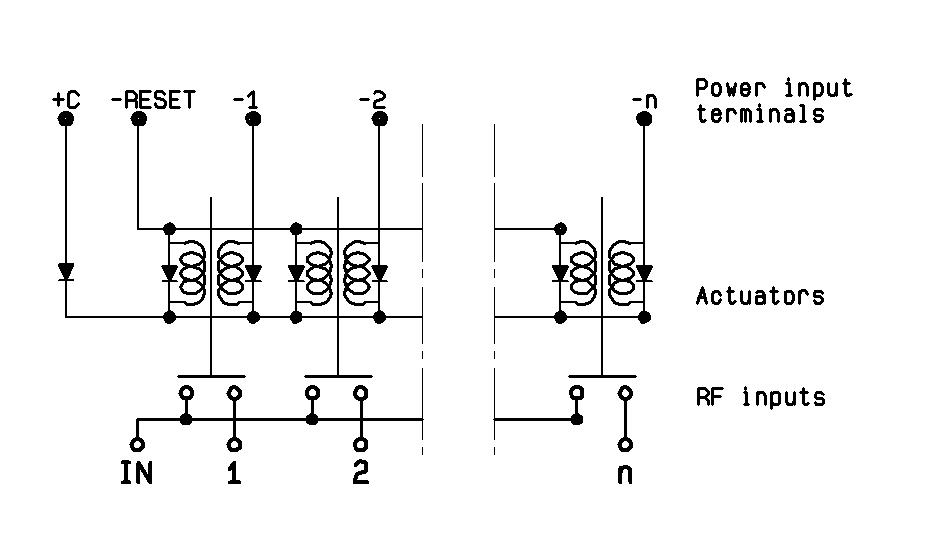
LATCHING SEPARATED RESET WITH POSITIVE COMMON
R591-6- -1-

LATCHING GLOBAL RESET WITH SUPPRESSION DIODES
R591-2- -3-
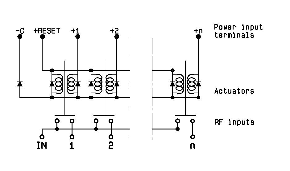
LATCHING SEPARATED RESET WITHOUT OPTION
R591-6- -0-
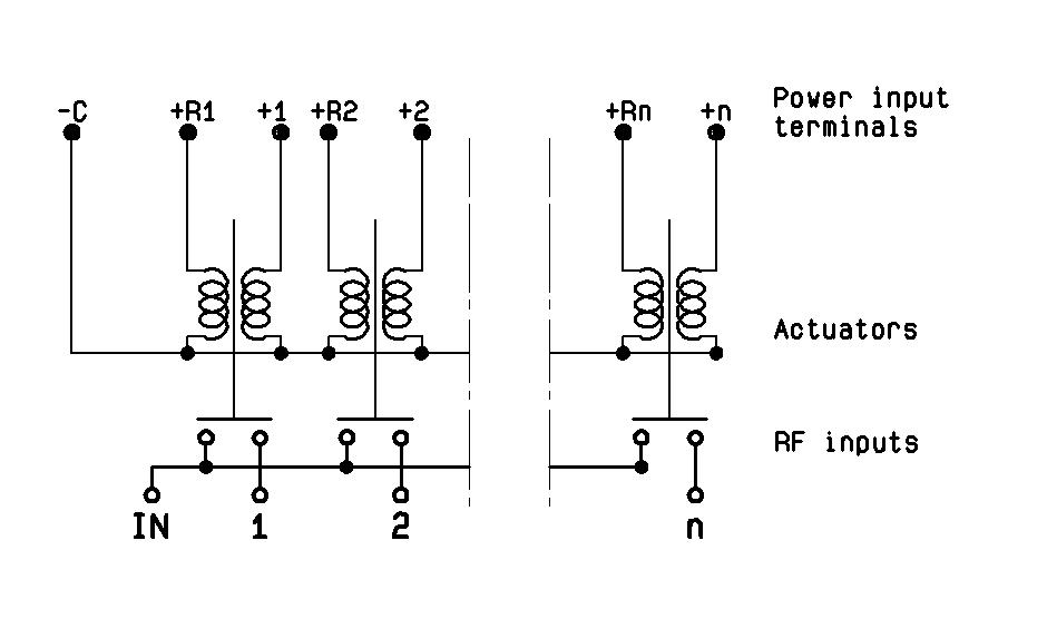
LATCHING SEPARATED RESET WITH SUPPRESSION DIODES
R591-6- -3-
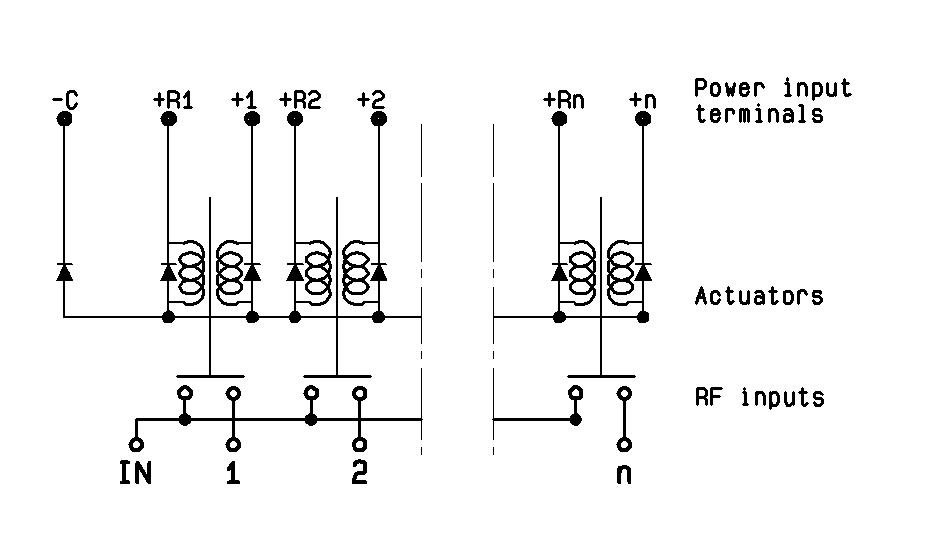
5-6 | SPNT SIMPLIFICATION IS OUR INNOVATION Visit www.radiall.com for more information
Subminiature Series
LATCHING SEPARATED RESET WITH POSITIVE COMMON & SUPPRESSION DIODES
R591-6- -4-
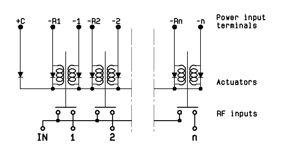
PIN IDENTIFICATION
SOLDER PINS (TOP VIEW) [1]
• 16 contact female connector
• NC: not connected
• For SP4T, ways 3 and 6 not connected
• Pin R = reset of all paths
Latching individual reset [2]
Normally open with TTL drive
Notes
1. Compatible with 2.54 mm pitch double row and HE10 connector.
2. Available with "solder pins" models only.
9 PIN MICRO-D (TOP VIEW)
SPNT | 5-7 SIMPLIFICATION IS OUR INNOVATION Visit www.radiall.com for more information
TYPE C V 1 2 3 4 5 6 R R1 R2 R3 R4 R5 R6 Normally open Negative common -C NC +1 +2 +3 +4 +5 +6 NC NC NC NC NC NC NC Positive common +C NC -1 -2 -3 -4 -5 -6 NC NC NC NC NC NC NC Latching
Negative common -C NC +1 +2 +3 +4 +5 +6 +reset NC NC NC NC NC NC Positive common +C NC -1 -2 -3 -4 -5 -6 -reset NC NC NC NC NC NC
global reset
Negative common -C NC +1 +2 +3 +4 +5 +6 NC +res 1 +res 2 +res 3 +res 4 +res 5 +res 6 Positive common +C NC -1 -2 -3 -4 -5 -6 NC -res �1 -res � 2 -res � 3 -res � 4 -res � 5 -res �6
- RTN VCC E1 E2 E3 E4 E5 E6 NC NC NC NC NC NC NC
SPNT USB UP TO 40 GHz
SMA – SMA 2.9
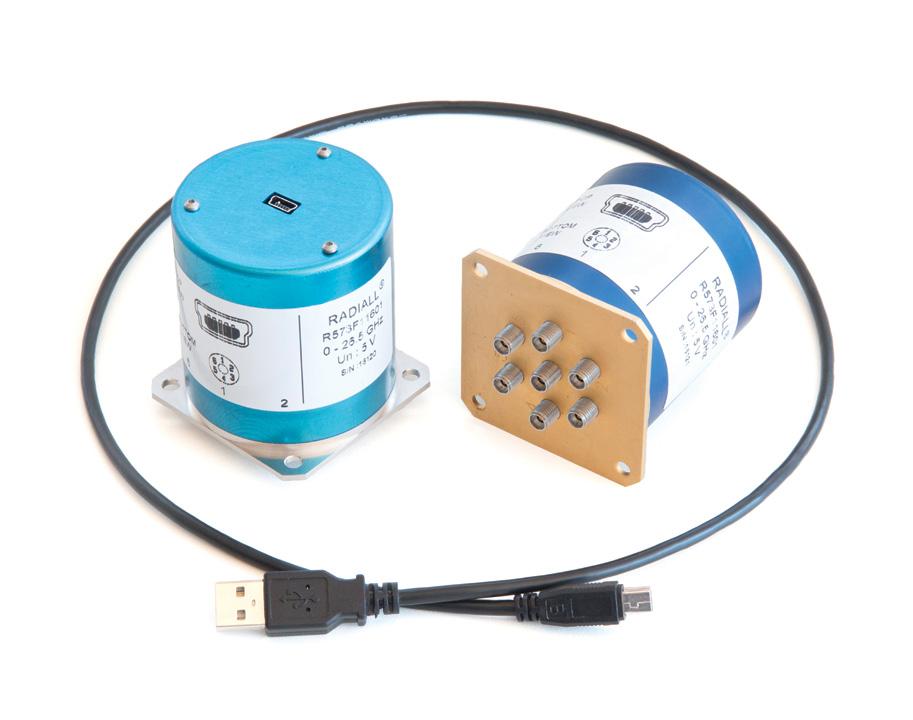
PART NUMBER SELECTION
SERIES PREFIX
MODEL
3: Without 50 Ω termination
4: With 50 Ω termination
RF CONNECTORS
F: SMA up to 26 � 5 GHz
8: SMA 2�9 up to 40 GHz [1 & 2]
TYPE
1: Normally open I + C
ACTUATOR VOLTAGE
1: 5 Vdc
NUMBER OF POSITIONS
6: 6 positions
8: 8 positions
OPTIONS
0: Without option
ACTUATOR TERMINALS
1: Mini USB socket
Utilizing Radiall’s proven and patented RAMSES concept, our team of experts and engineers integrated a mini-USB terminal on SP6T and SP8T switches for simplified use especially in test & lab applications.
Featuring an easy-to-integrate design, USB Coaxial Switches are delivered with a 1 meter long USB cable for power supply and switch drive. A soft front panel is provided to control the switches but commonly used software programming platforms such as Visual Basic, C#, C++, LabVIEW and VEE are also compatible
Example of P/N: R573F11601 is a non-terminated SP6T SMA up to 26.5 GHz, Normally Open, 5 Vdc, Indicators with a mini USB port.
Notes
I.C.: Indicator contact
1. Available only with 6 positions.
2. Connector SMA 2.9 is equivalent to "K connector ®", registered trademark of Anritsu.
R57 1 1 1 0
5-8 | SPNT SIMPLIFICATION IS OUR INNOVATION Visit www.radiall.com for more information
USB Series
APPLICATION NOTE
USB coaxial switch as cascade
You can use as many USB switches in cascade as you want. Each product is recognized by its automatic affectation to the ComPort and in order to differentiate them, each product has its own serial number which can be read by the software.
In order to provide power supply (5V / 420mA) and drive as many switches as you want with your computer, you will need a hub USB which can provide same power as a classic USB port of the computer (500mA / 5V) or a PCI expansion card USB (if it is a desktop)�
APPLICATION EXAMPLE
AFTER BEFORE
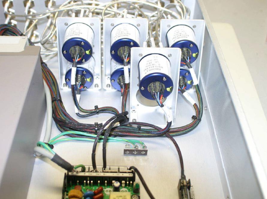
DC power from a power supply and wires to provide power to PF Paths

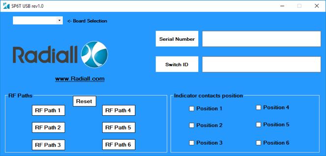
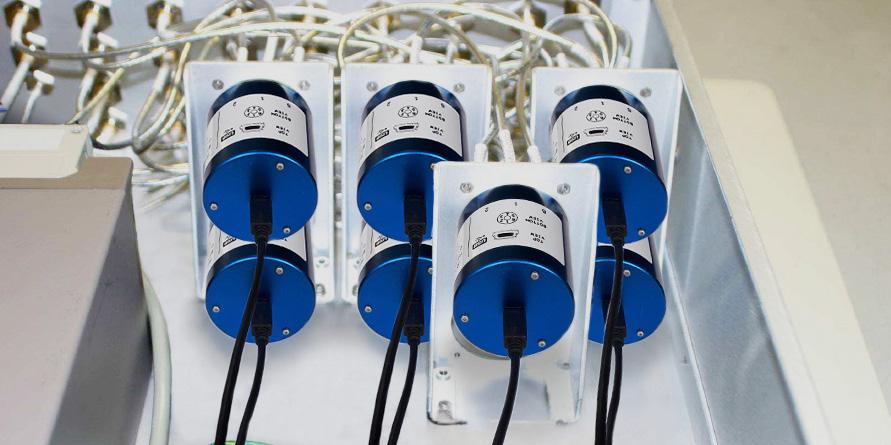
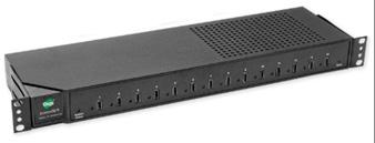
Control with computer
GRAPHICAL USER INTERFACE WITH MORE THAN ONE PRODUCT
• Every product has its own serial port. To control manually you can also open many soft front panel.
• Each product has its own serial number and different communication port.
• The user has also the possibility to manage the control automatically using LabView drivers provided or using Vb.net, C++ , C# with DLL provided also.
SPNT | 5-9 SIMPLIFICATION IS OUR INNOVATION Visit www.radiall.com for more information USB Series
USB Cable mini B to Type A
GENERAL SPECIFICATIONS
OPERATING
Average Power See Power Rating Chart page 1-13
Indicator rating Indicators status are returned by software
Switching time (max) ms 15 ms
Non-terminated SP6T (R573 series)
Life (min)
Connectors
Actuator terminals
Terminated SP6T (R574 series)
SP8T (all models)
Vibration (MIL STD 202, method 204D, cond D)
Shock (MIL STD 202, method 213B, cond C)
RF PERFORMANCE - SP6T
CONNECTORS FREQUENCY RANGE GH z
RF PERFORMANCE - SP8T
CONNECTORS
5-10 | SPNT SIMPLIFICATION IS OUR INNOVATION Visit www.radiall.com for more information USB Series
V.S.W.R. (MAX) INSERTION LOSS (MAX) dB ISOLATION (MIN) dB IMPEDANCE Ω SMA DC - 26 5 DC - 6 1 20 0� 3 + 0�015 x frequency (GHz) 80 50 6 - 12 4 1 35 70 12 4 - 20 1 45 65 20 - 26 5 1 70 60 SMA 2 9 DC - 40 DC - 6 1� 20 80 6 - 12 4 1 35 70 12 4 - 18 1 45 65 18 - 26 5 1 70 60 26 5 - 40 1 90 55
Vdc 5 Coil resistance (+/-10%) Ω 11 9
operating
mA 420
MODE NORMALLY OPEN Nominal operating voltage
Nominal
current at 23 ºC
SMA SMA 2 9 5 million cycles 2 million cycles
million
2
cycles
SMA - SMA
9
2
Mini USB socket
SMA - SMA 2 9 -25 ºC to +75 ºC
SMA
SMA
9 -55
to +85
Operating temperature range
Storage temperature range
-
2
ºC
ºC
10 - 2,000 Hz , 20 g operating - switch only
100 g / 6 ms, 1/2 sine operating - switch only
FREQUENCY RANGE GH z V.S.W.R. (MAX) INSERTION LOSS (MAX) dB ISOLATION (MIN) dB IMPEDANCE Ω SMA DC - 26 � 5 DC - 3 1 20 0 20 80 50 3 - 8 1 30 0 30 70 8 - 12 4 1 40 0 40 60 12 � 4 - 16 1� 50 0� 55 60 16 - 18 1 60 0 60 60 18 - 22 1 70 0 70 60 22 - 26 5 2 00 1 10 55
TYPICAL RF PERFORMANCE
Example: SP6T SMA up to 26.5 GHz
INSERTION LOSS & ISOLATION
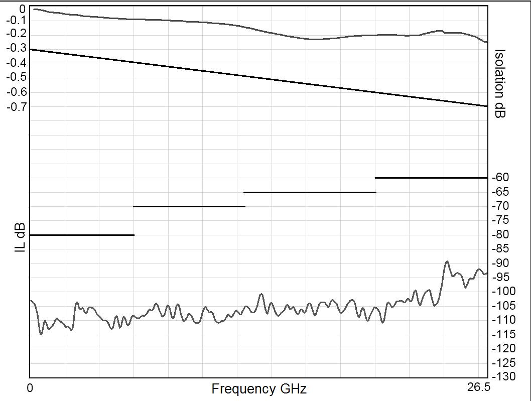
Frequency (GHz)
Example: SP6T SMA 2.9 up to 40 GHz
INSERTION LOSS & ISOLATION
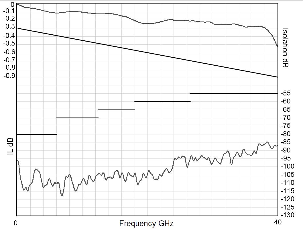
Frequency (GHz)
Example: SP8T SMA 2.9 up to 26.5 GHz
INSERTION LOSS & ISOLATION
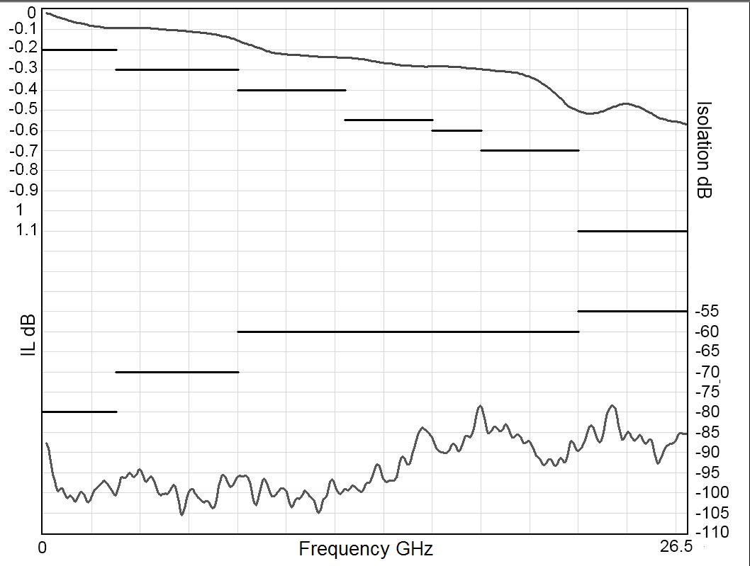
Frequency (GHz)
V.S.W.R
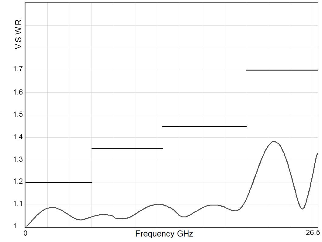
Frequency (GHz)
V.S.W.R
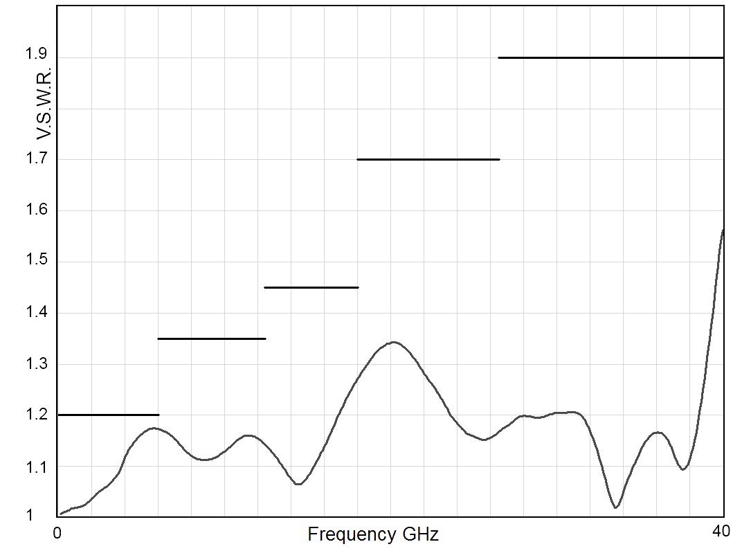
Frequency (GHz)
V.S.W.R
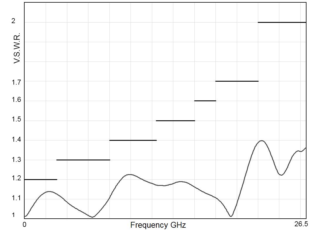
Frequency (GHz)
SPNT | 5-11 SIMPLIFICATION IS OUR INNOVATION Visit www.radiall.com for more information
USB Series
TYPICAL OUTLINE DRAWINGS
Non-terminated or terminated 6 positions
SMA MODEL
Notes
All dimensions are in millimeters [inches].
5-12 | SPNT SIMPLIFICATION IS OUR INNOVATION Visit www.radiall.com for more information USB Series
SMA 2.9 MODEL
TYPICAL OUTLINE DRAWINGS
Non-terminated or terminated 8 positions
SMA MODEL
Notes
All dimensions are in millimeters [inches]. For electrical schematics see page 5-43.
SPNT | 5-13 SIMPLIFICATION IS OUR INNOVATION Visit www.radiall.com for more information USB Series
SPNT TERMINATED & NON-TERMINATED UP TO 50 GHz SMA – SMA 2.9 - 2.4 MM - QMA - DIN 1.6 / 5.6
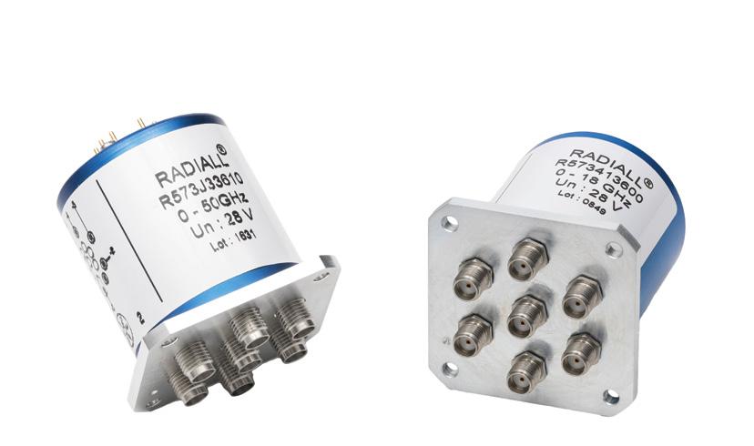
Radiall's R573 and R574 multi-throw coaxial switches are offered in many configurations (over 40,000 possible combinations) including terminated and non-terminated options. Radiall offers reliable products, with shorter delivery times and competitive pricing. Excellent typical RF performance make RAMSES switches (40 GHz) ideal for Automated Test Equipment (ATE) and other measurement applications. These switches are suitable for defense, industrial, instrumentation and telecommunication applications �
Example of P/N: R574453605 is a terminated SP6T SMA up to 18 GHz, Latching, Self Cut-Off, 28 Vdc, Indicators and male 25 pin D-Sub connector.
SERIES PREFIX
MODEL
3: Without 50 Ω termination
4: With 50 Ω termination
RF CONNECTORS
3: SMA up to 3 GHz
E: QMA up to 6 GHz [4, 5 & 13]
4: SMA up to 18 GHz [2]
F: SMA up to 26 � 5 GHz [6]
8: SMA 2 9 up to 40 GHz [4 & 14]
J: 2 4 mm up to 50 GHz [11]
9: DIN 1 6/5 6 up to 2 5 GHz [4 & 5]
TYPE
0: Normally open
1: Normally open I � + C �
2: Latching
3: Latching + I.C.
4: Latching + S.C.O. [1 & 4]
5: Latching + S.C.O. + I.C. [1 & 4]
8: Latching + S.C.O. + A.R. [1]
9: Latching + S.C.O. + I.C. + A.R. [1]
Notes
I.C.: Indicator contact / S.C.O. : Self Cut-Off / A.R. : Auto Reset
1. These models are already equipped with suppression diodes
2. 12 positions are available only up to 12.4 GHz, for 12 positions up to 18 GHz select digit F
3. Latching BCD driver enables also a global reset through driver code 0000 (see BCD logic coding page 1-11)
4. Available only up to 6 positions
5. Model "3" only
6. 10 positions are available only up to 22 GHz, 12 positions only up to 18 GHz
7. From 3 to 8 positions, this option is only available for type 0, 1, 2, 3 and for type 8 and 9 combined with 28 Vdc. From 10 to 12 positions, only for type 0, 1, 2 and 3 PART NUMBER SELECTION
ACTUATOR TERMINALS
0: Solder pins
5: D-Sub connector
OPTIONS [15]
0: Without option
1: Positive common [7]
2: Compatible TTL driver [1, 9 & 10]
3: With suppression diodes
4: With suppression diodes and positive common [12]
8: BCD TTL driver compatible [1, 3, 8 & 9]
NUMBER OF POSITIONS
3: 3 positions
4: 4 positions
5: 5 positions
6: 6 positions
8: 8 positions
0: 10 positions
2: 12 positions
ACTUATOR VOLTAGE
2: 12 Vdc
3: 28 Vdc

8. Option available only with type 0, 1, 8 and 9
9. Polarity is not relevant to application for switches with TTL driver
10 From 8 to 12 positions, this option is only available with type 0, 1, 8 and 9.
11. Available only with 4 and 6 positions.
12. Option available only with type 0, 1, 2, and 3.
13. The QLF tradermark (quick lock formula®) standard applies to QMA and QN series and guaranties the full intermateability between suppliers using this tradermark. Using QLF certificied connectors also guarantees the specified level of RF performance
14. Connector SMA 2.9 is equivalent to "K connector ®", registered trademark of Anritsu
15. For precisions see availabilty of options chart page 5-9
5-14 | SPNT SIMPLIFICATION IS OUR INNOVATION Visit www.radiall.com for more information
RAMSES Series
R57
RAMSES Series
GENERAL SPECIFICATIONS
Type 2, 3, 4 and 5:
Latching models have a RESET pin which commands the reset of all positions. This command should be used before switching from one position to another. If not, two positions will be set at the same time.
Note: During the RESET operation the global current is: the nominal operating current multiplied by the number of positions.
Type 8, 9:
Latching models with AUTOMATIC RESET are available; these products have an internal SET/RESET circuit which automatically resets all the non-selected positions and sets the desired position. This option simplifies the use of latching switches by suppressing the RESET command in switching sequence.
An electronic circuit supplies successively groups of 2, 3 or 4 actuators, in order to limit the maximum current. The current with this option is the total current of 2, 3 or 4 reset coils in the same time (see table below).
Example: During the AUTOMATIC RESET operation, at 28 Vdc, 4 position switch has a temporary consumption of only 250 mA, during 40 ms maximum.
SWITCHING SEQUENCE
SP10 & 12 T FOR SP6 TO 8T
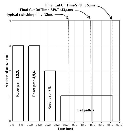
n = number of positions
OPERATING TOTAL CURRENT AT 23 °C (MA) SPNT LATCHING
NUMBER OF POSITIONS
3 to 4 320 × n 640 125 × n 250
5 to 8 320 × n 960 125 × n 375
10 to 12 320 × n 1280 125 × n 500
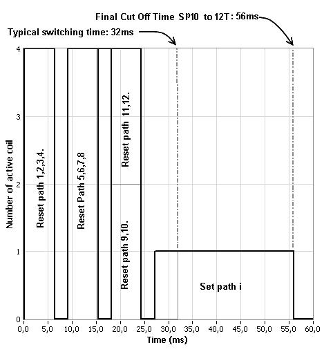
Availability of options according to both type and number of positions.
SPNT | 5-15 SIMPLIFICATION IS OUR INNOVATION Visit www.radiall.com for more information
TYPE NUMBERS OF POSITIONS AVAILABLE OPTIONS 0 or 1 3 to 12 0 - 1 - 2 - 3 - 4 - 8 2 or 3 3 to 6 0 - 1 - 2 - 3 - 4 8 to 12 0 - 1 - 3 - 4 4 or 5 3 to 6 0 - 2 8 to 12 N/A 8 or 9 3 to 8 0 - 1 - 2 - 8 10 & 12 0 - 2 - 8
12
28
MANUAL RESET AUTOMATIC RESET MANUAL RESET AUTOMATIC RESET
VOLTS
VOLTS
FOR
GENERAL SPECIFICATIONS
OPERATING MODE NORMALLY OPEN
Nominal operating voltage (across operating temperature)
Average power
High Level
TTL input
(10 2/13)
(24/30)
(10 2/13)
(24/30)
See table on previous page
See Power Rating Chart page 1-13
2.2 to 5.5 V (TTL Option) / 800 μA max 5.5 volts 3 5 to 5 5 V (BCD Option)
Low Level 0 to 0.8 V (TTL Option) / 20 μA max 0.8 volts 0 to 1 5 V (BCD Option)
Indicator rating 1 W / 30 V / 100 mA
Switching time (Max) ms 15 ms
For automatic reset models: SP3T to SP6T = 40 ms SP8T to SP12T = 50 ms
Non-terminated SP3 to 6T (R573 series) SMA - QMA SMA 2 9 - 2 4 mm - 1 6/5 6 5 million cycles 2 million cycles
Life (Min)
Terminated SP3 to 6T (R574 series) 2 million cycles SP8 to 12T (all models)
Connectors
Actuator terminals
- SMA 2 9 - 2 4 mm - QMA - DIN 1 6/5 6
Solder pins or male 25 pin D-sub connector
Operating temperature range 2 4 mm - DIN 1 6/5 6 -25 ºC to +70 ºC SMA - SMA 2 9 - QMA -40 ºC to +85 ºC
Storage temperature range 2 4 mm - DIN 1 6/5 6 -40 ºC to +85 ºC
SMA - SMA 2 9 - QMA -55 ºC to +85 ºC
Vibration (MIL STD 202, method 204D, cond � D) 10 - 2,000 Hz , 20 g operating for SP3 to 6T, survival for SP8 to 12T
Shock (MIL STD 202, method 213B, cond C) 100 g / 6 ms, 1/2 sine operating for SP3 to 6T, survival for SP8 to 12T
RF PERFORMANCE - SMA CONNECTOR
NUMBER OF POSITIONS
5-16 | SPNT SIMPLIFICATION IS OUR INNOVATION Visit www.radiall.com for more information
12
28
12
28
Coil resistance
47 5 275
LATCHING
Vdc
(+/-10%) Ω
Nominal operating
mA 250 102
current at 23 ºC
SMA
RAMSES Series
FREQUENCY RANGE GH z V.S.W.R. (MAX) INSERTION LOSS (MAX) dB ISOLATION (MIN) dB IMPEDANCE Ω
to 6 DC - 3 DC - 18 DC - 26 5 DC - 3 1� 20 0� 20 80 50 3-8 1 30 0 30 70 8 - 12 4 1 40 0 40 60 12 4 - 18 1 50 0 50 60 18 - 26 5 1 70 0 70 50 8 DC - 3 DC - 26 � 5 DC - 3 1 20 0 20 80 3 - 8 1 30 0 30 70 8 - 12 4 1 40 0 40 60 12 � 4 - 16 1� 50 0� 55 60 16 - 18 1 60 0 60 60 18 - 22 1 70 0 70 60 22 - 26 � 5 2 �00 1�10 55 10 DC - 3 DC - 22 DC - 3 1 20 0 20 80 3 - 8 1 30 0 30 70 8 - 12 4 1 40 0 40 60 12 4 - 15 5 1 50 0 50 60 15 5 - 18 1 70 0 70 55 18 - 22 1 80 0 80 55 12 DC - 3 DC - 18 DC - 3 1 20 0 20 80 3 - 8 1� 40 0� 40 70 8 - 12 4 1 60 0 60 60 12 4 - 15 1 70 0 70 60 15 - 18 1� 80 0� 80 50
3
RAMSES Series
RF PERFORMANCE
CONNECTORS
R573 & R574 TYPICAL PERFORMANCE
Example: SP6T QMA up to 6 GHz
INSERTION LOSS & ISOLATION
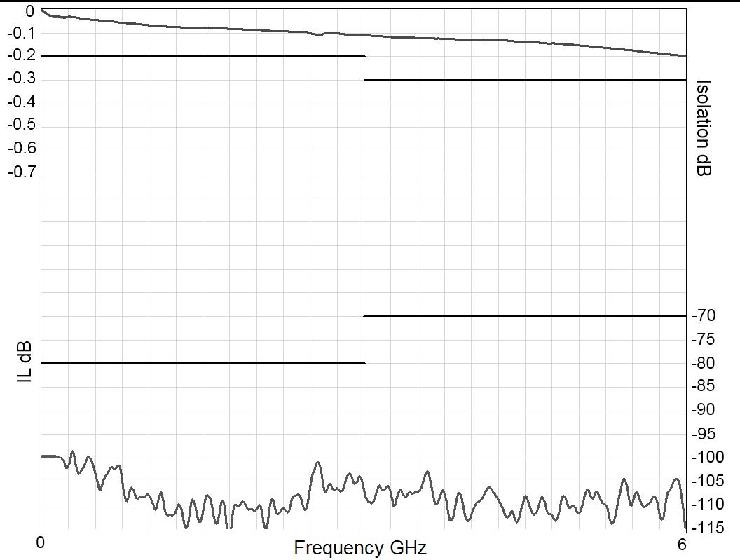
V.S.W.R.
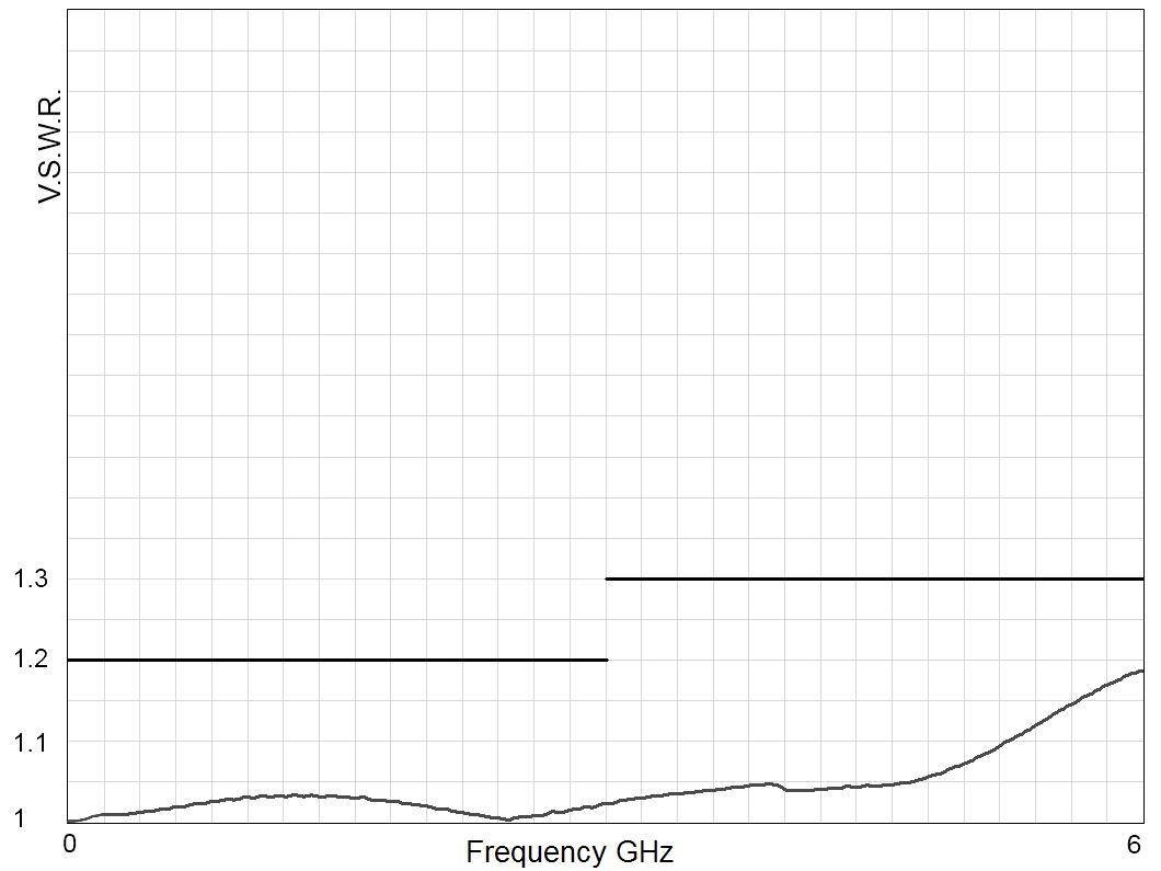
SPNT | 5-17 SIMPLIFICATION IS OUR INNOVATION Visit www.radiall.com for more information
NUMBER OF POSITIONS FREQUENCY RANGE GH z V.S.W.R. (MAX) INSERTION LOSS (MAX) D B ISOLATION (MIN) D B IMPEDANCE Ω SMA 2 9 3 to 6 DC - 40 DC - 6 1� 30 0� 20 70 50 6 - 12 4 1 40 0 40 60 12 4 -18 1 50 0 50 60 18 - 26 5 1 70 0 70 55 26 5 - 40 2 20 1 10 50 2 4 mm 4 or 6 DC - 50 DC - 6 1 30 0 20 70 6 - 12 4 1 40 0 40 60 12 4 - 18 1 50 0 50 60 18 - 26 5 1 70 0 70 55 26 5 - 40 1 90 0 90 50 40 - 50 2 20 1 20 50 1 6/5 6 3 to 6 DC - 2 5 DC - 1 1� 30 0� 20 80 75 1 - 2 5 1 40 0 30 70 QMA 3 to 6 DC - 6 DC - 3 1 20 0 20 80 50 3 - 6 1 30 0 30 70
Frequency (GHz) Frequency (GHz)
RAMSES Series
Example: Non-terminated SP6T up to 26.5 GHz
INSERTION LOSS & ISOLATION
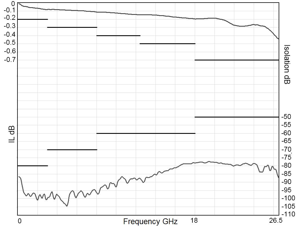
Frequency (GHz)
Example: Non-terminated SP6T SMA 2.9 up to 40 GHz
INSERTION LOSS & ISOLATION
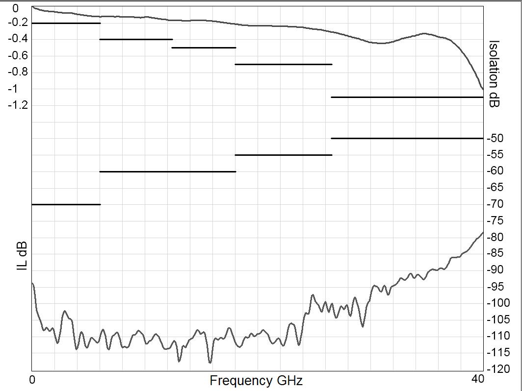
Frequency (GHz)
Example: Non-terminated SP6T 2.4 mm up to 50 GHz
INSERTION LOSS & ISOLATION
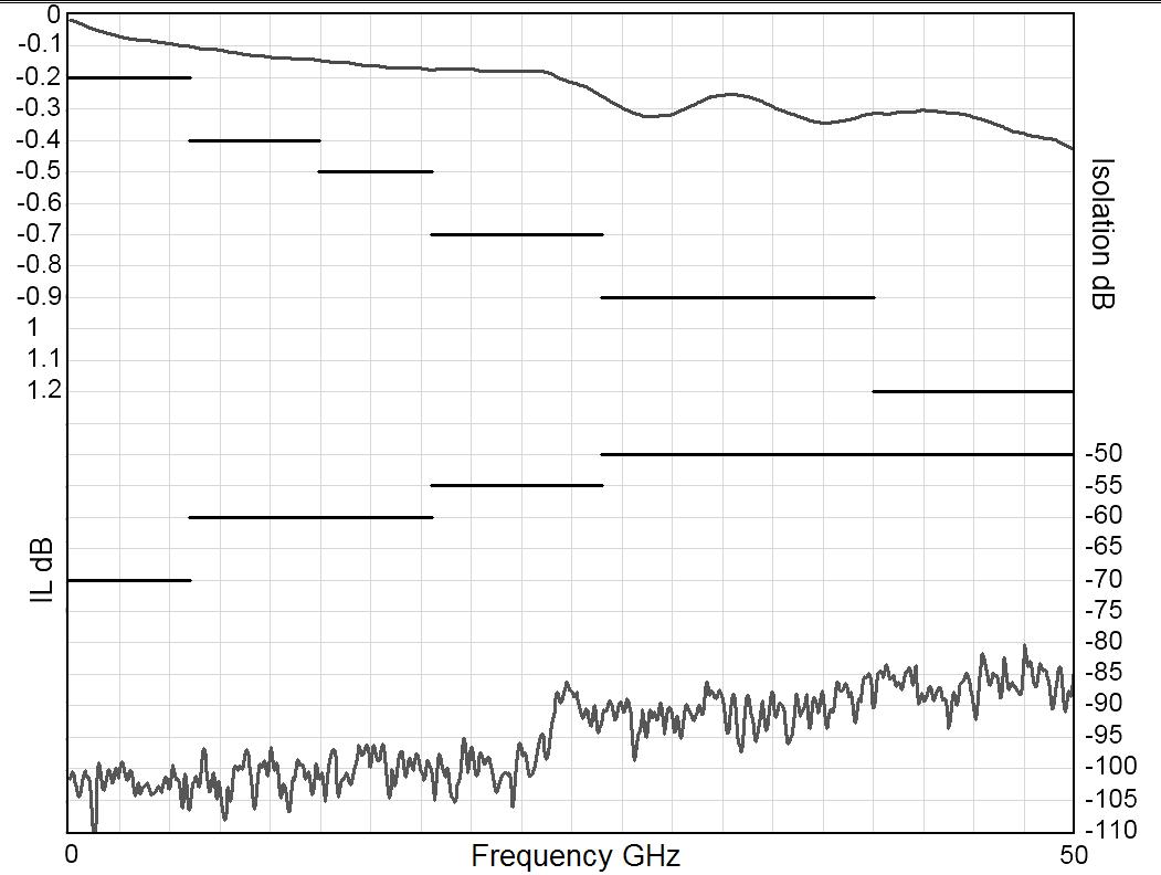
Frequency (GHz)
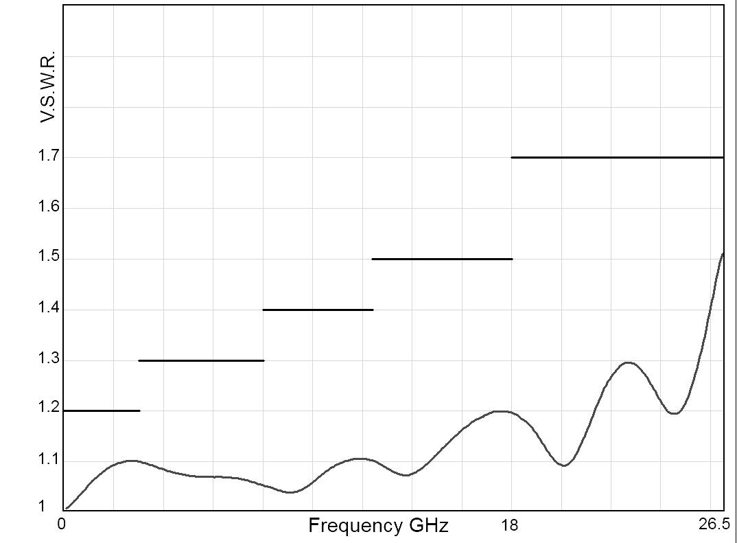
Frequency (GHz)
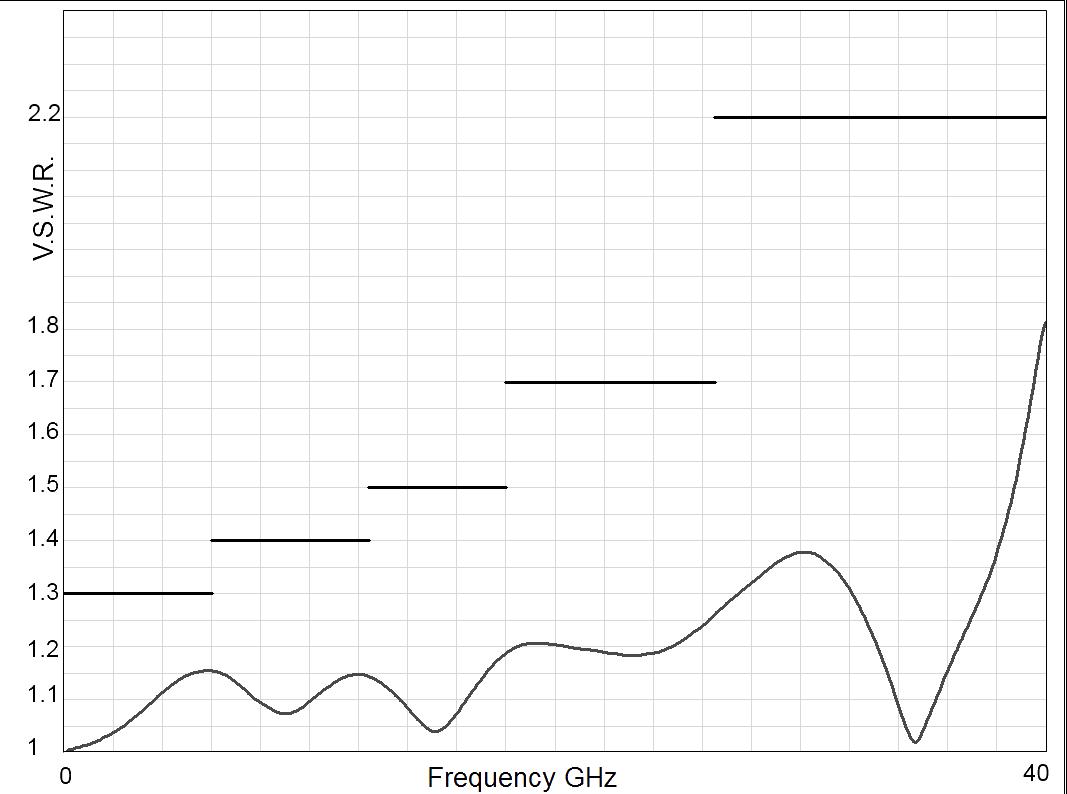
Frequency (GHz)
V.S.W.R
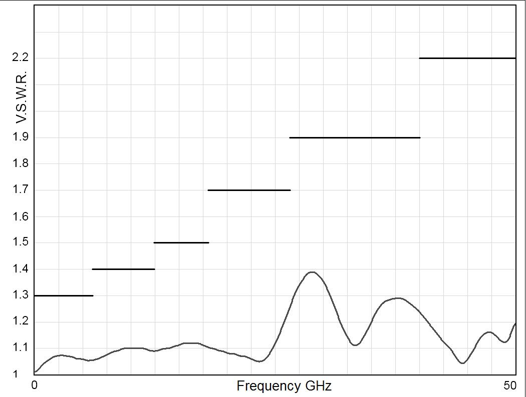
Frequency (GHz)
5-18 | SPNT SIMPLIFICATION IS OUR INNOVATION Visit www.radiall.com for more information
V.S.W.R
V.S.W.R
RAMSES Series
Example: Terminated SP6T up to 26.5 GHz
INSERTION LOSS & ISOLATION
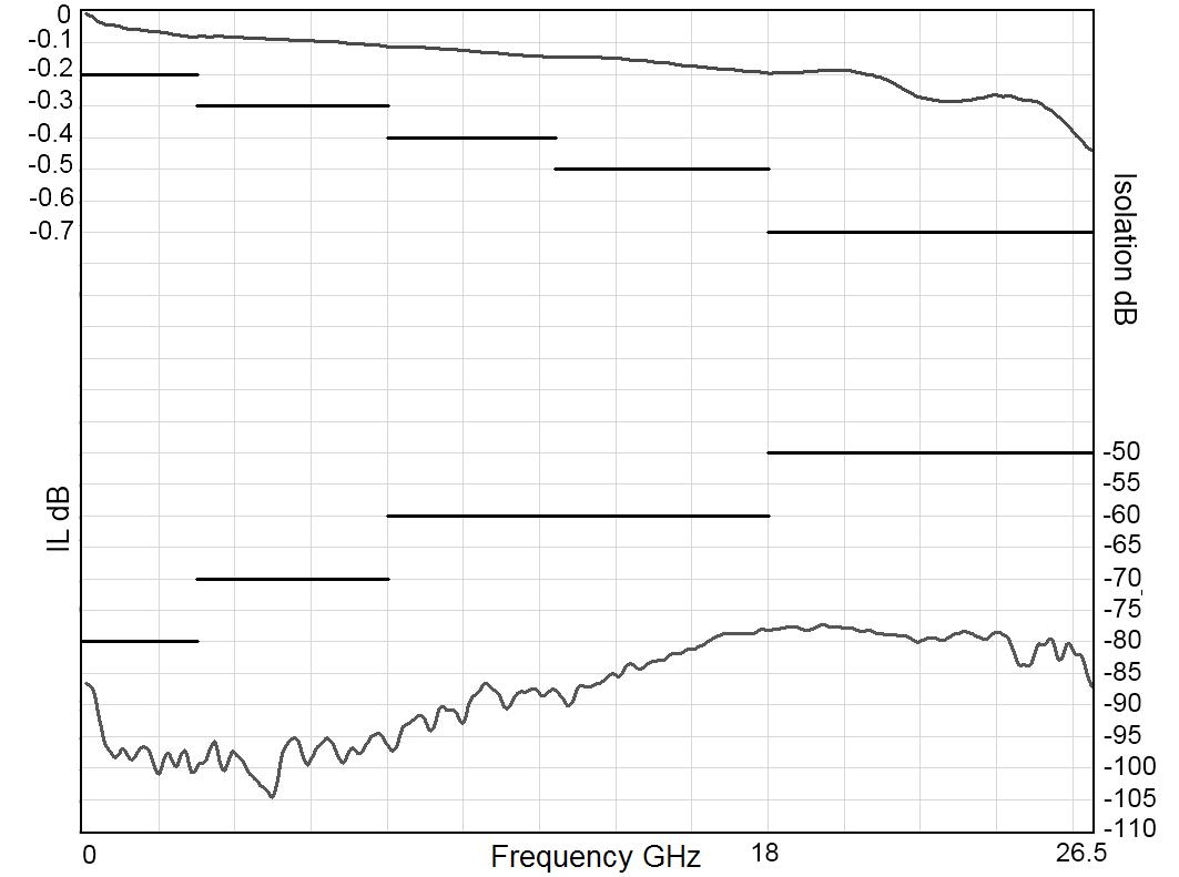
Frequency (GHz)
Example: Terminated SP6T SMA 2.9 up to 40 GHz
INSERTION LOSS & ISOLATION
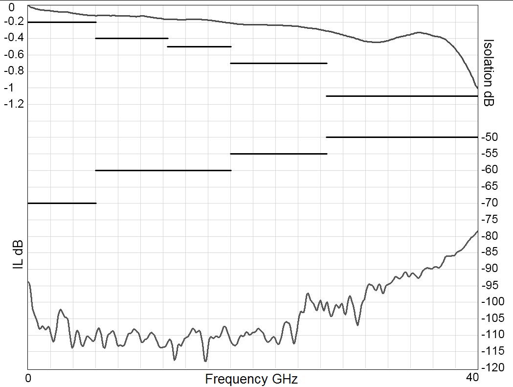
Frequency (GHz)
Example: Terminated SP6T 2.4 mm up to 50 GHz
INSERTION LOSS & ISOLATION
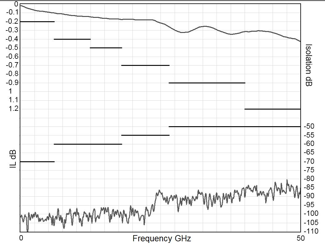
Frequency (GHz)
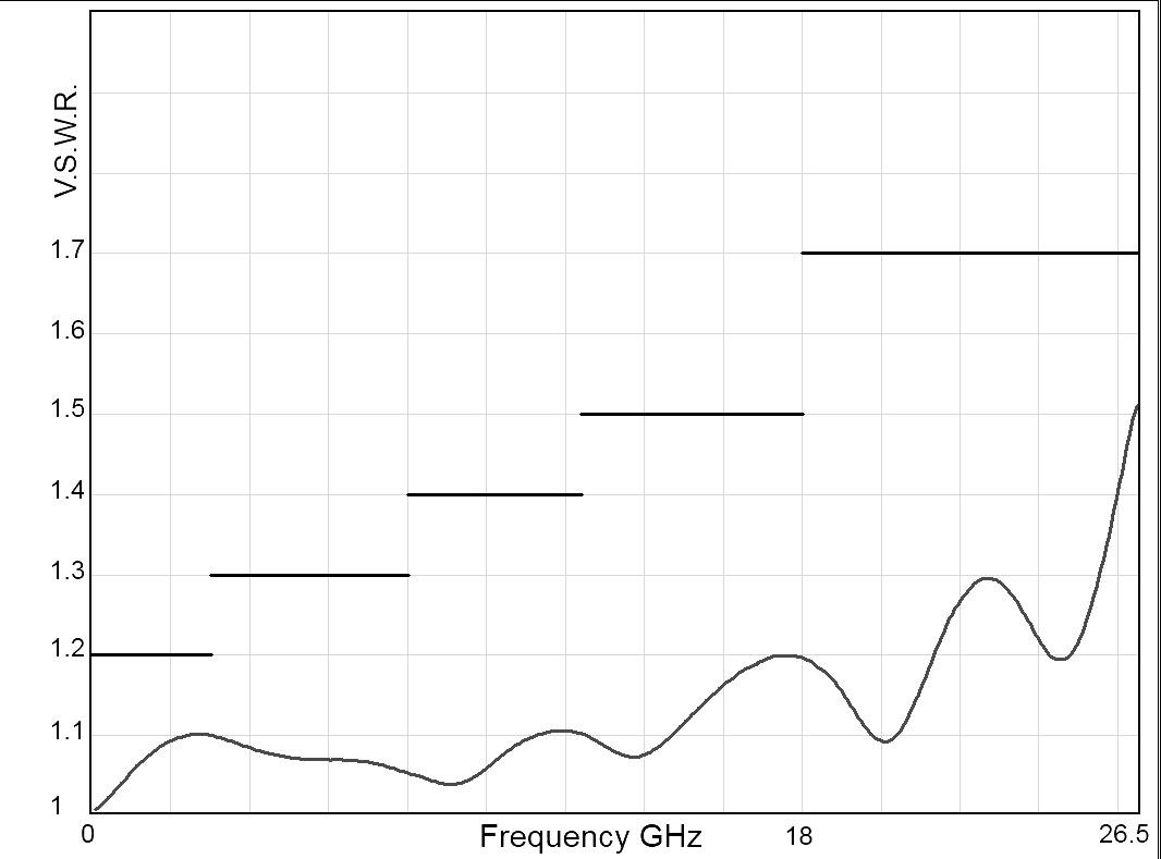
Frequency (GHz)
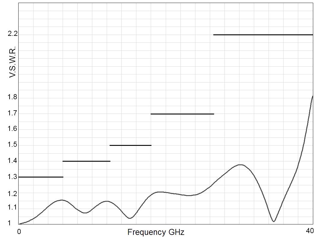
Frequency (GHz)
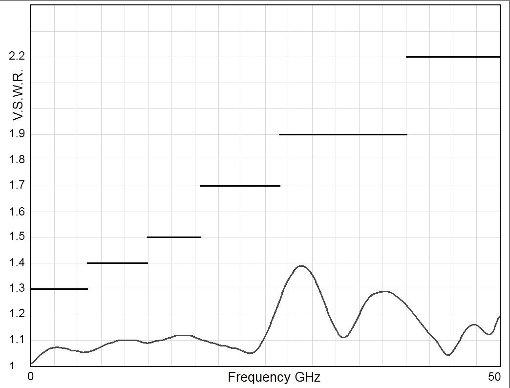
Frequency (GHz)
SPNT | 5-19 SIMPLIFICATION IS OUR INNOVATION Visit www.radiall.com for more information
V.S.W.R
V.S.W.R
V.S.W.R
RAMSES Series
Example: Non-terminated SP6T 1.6/5.6 up to 2.5 GHz
INSERTION LOSS & ISOLATION
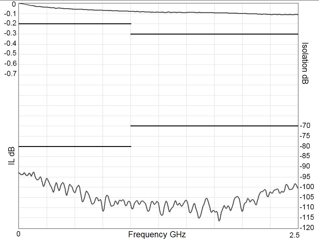
Frequency (GHz)
Example: SP8T SMA up to 26.5 GHz
INSERTION LOSS & ISOLATION
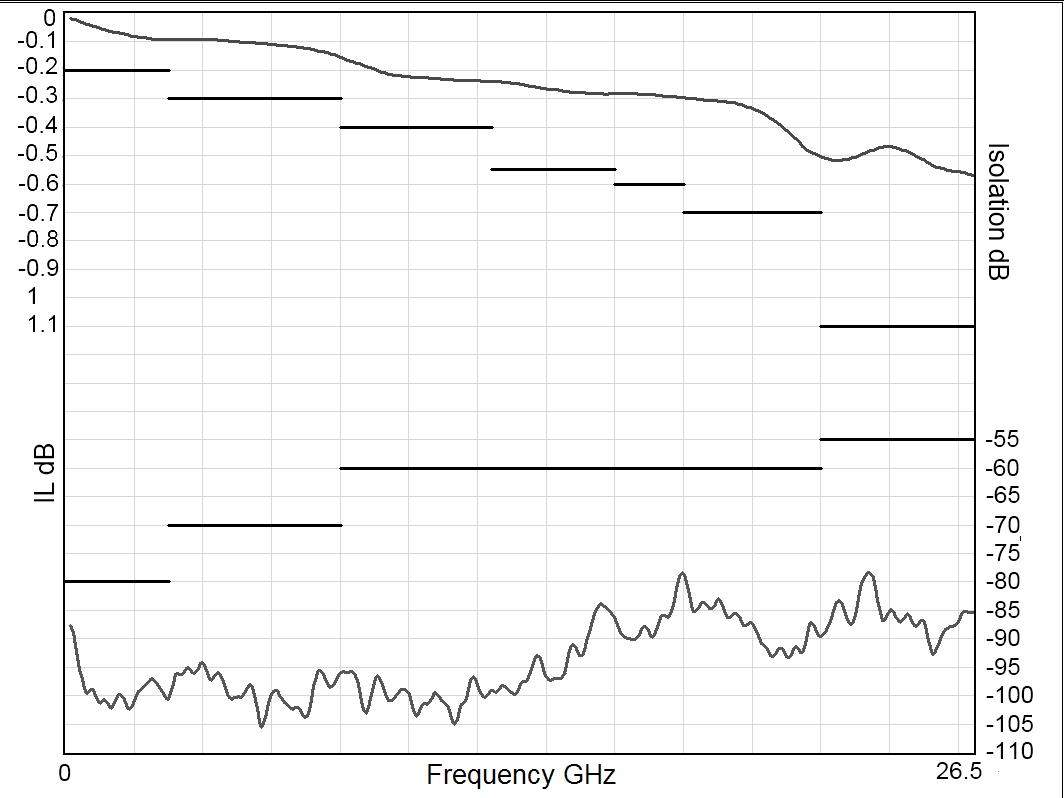
Frequency (GHz)
Example: SP10T SMA up to 22 GHz
INSERTION LOSS & ISOLATION
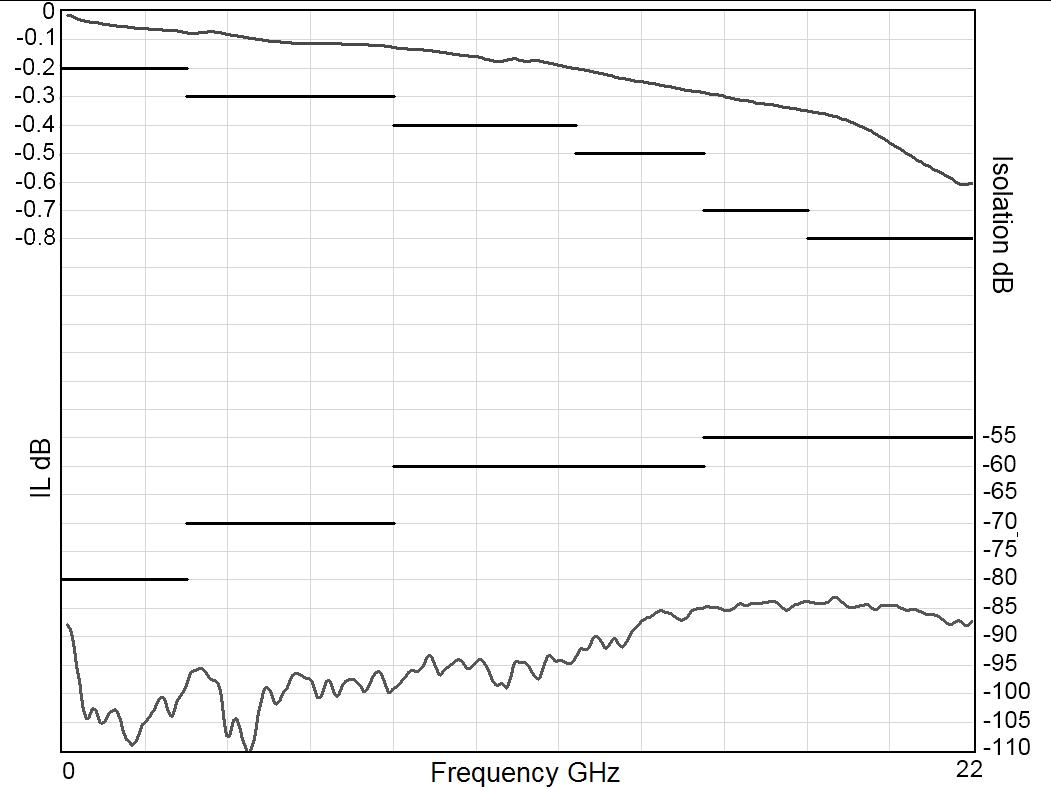
Frequency (GHz)
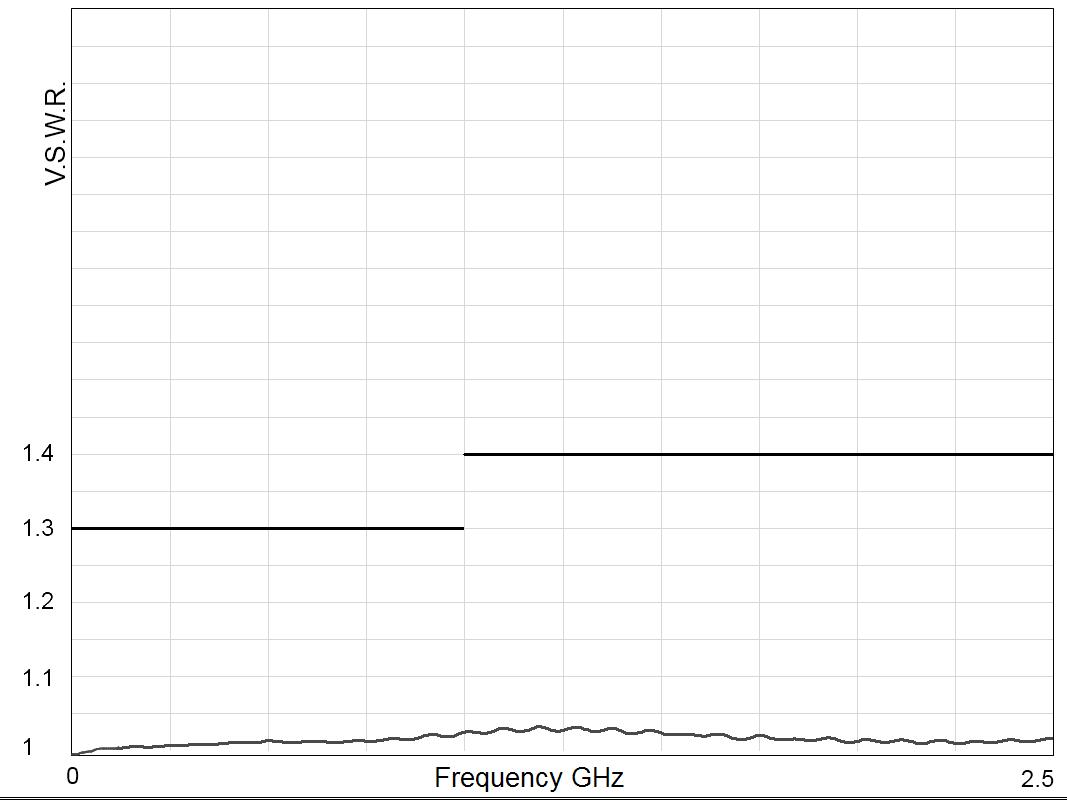
Frequency (GHz)
V.S.W.R
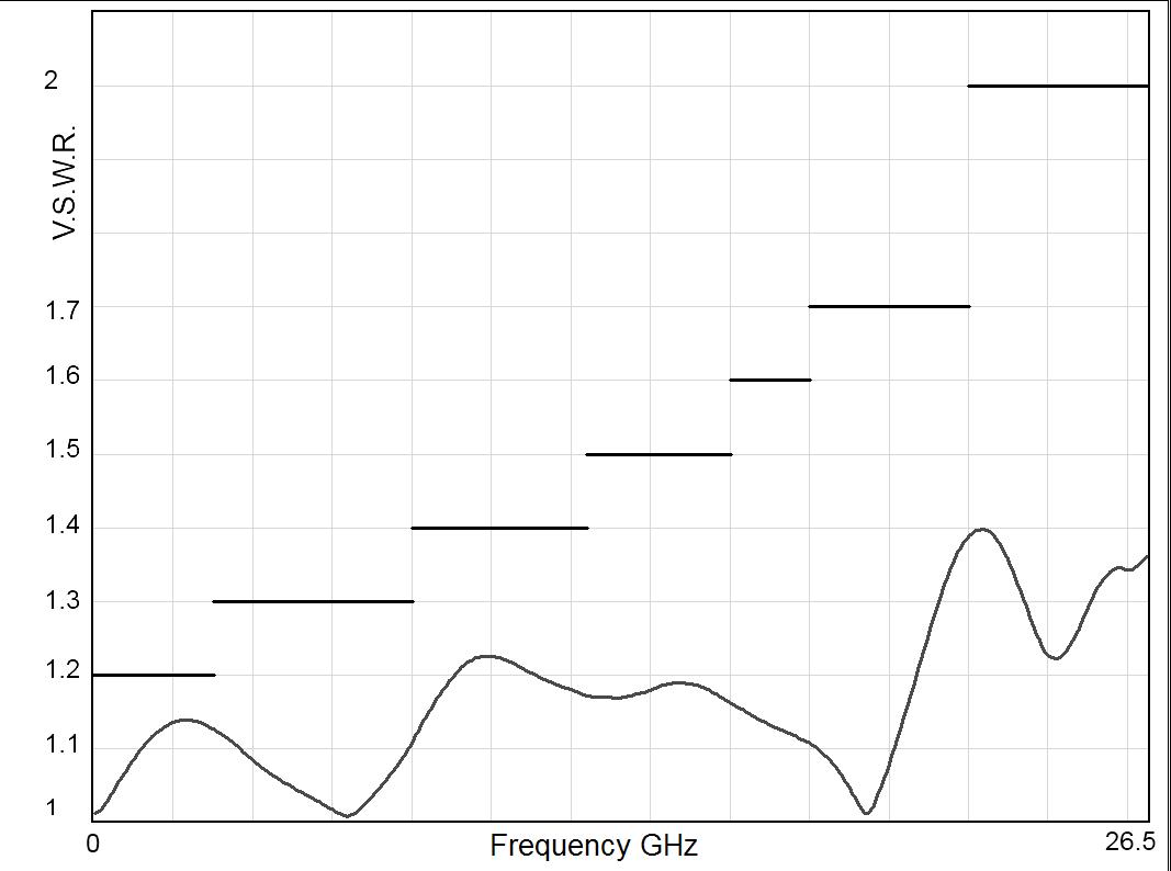
Frequency (GHz)
V.S.W.R
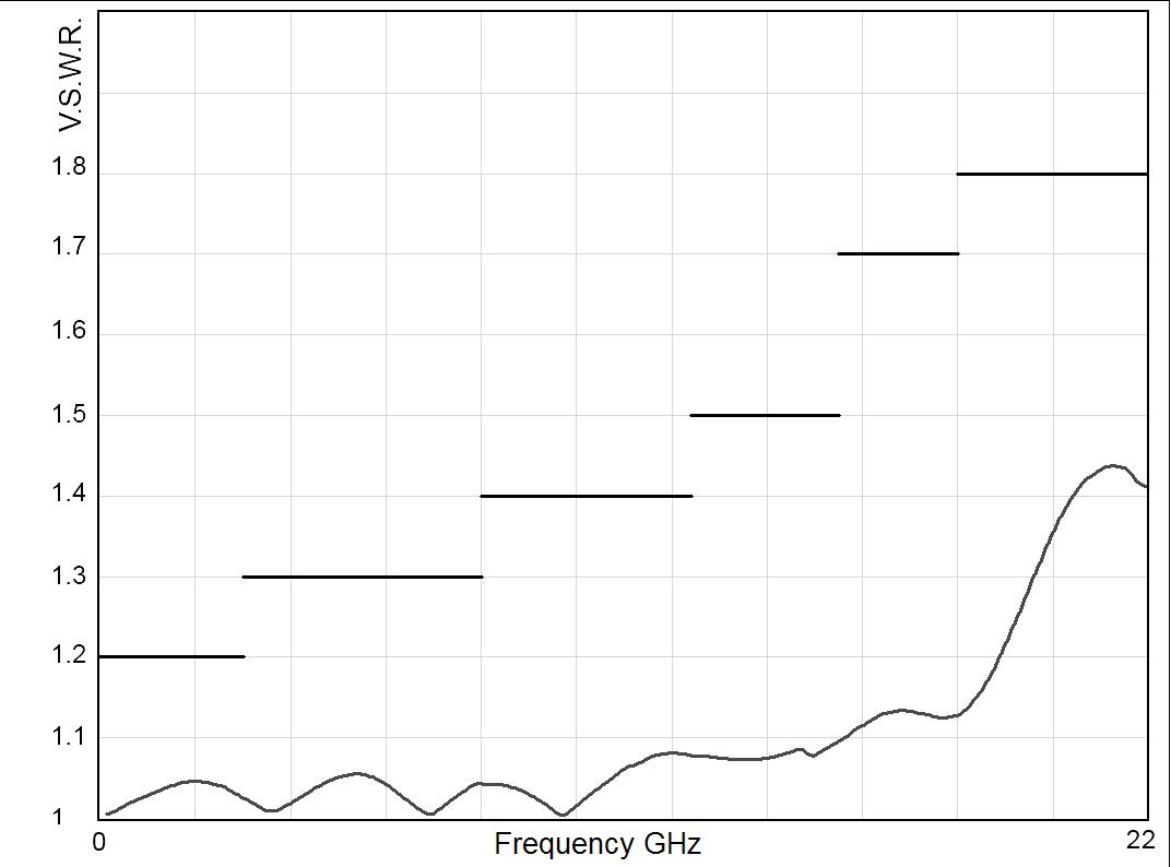
Frequency (GHz)
5-20 | SPNT SIMPLIFICATION IS OUR INNOVATION Visit www.radiall.com for more information
V.S.W.R
RAMSES Series
Example: SP12T SMA up to 18 GHz
INSERTION LOSS & ISOLATION
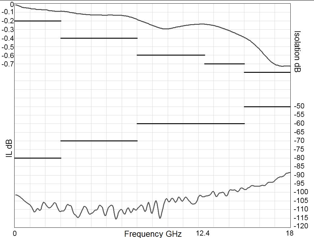
Frequency (GHz)
TYPICAL OUTLINE DRAWINGS
NON-TERMINATED 3 TO 6 POSITIONS
CONNECTORS A MAX (MM [INCHES])
SMA up to 26 5 GHz
7 7 [0 303]
SMA 2 9 up to 40 GHz 6 7 [0 264]
2 4 mm up to 50 GHz 6 7 [0 264]
QMA up to 6 GHz 10 8 [0 394]
DIN 1 6 / 5 6 up to 2 5 GHz 11 5 [0 433]
SOLDER PINS
Type 0 or 1 with option 0 - 1 - 3 or 4
Type 2 or 3 with option 0 or 1
Notes All dimensions are in millimeters [inches].
V.S.W.R
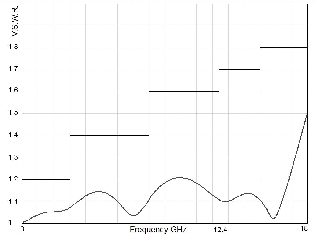
Frequency (GHz)
SPNT | 5-21 SIMPLIFICATION IS OUR INNOVATION Visit www.radiall.com for more information
RAMSES Series
TYPICAL OUTLINE DRAWINGS
NON-TERMINATED 3 TO 6 POSITIONS (CONTINUED)
Type 0 or 1 with option 2 or 8
SOLDER PINS
Type 2 or 3 with option 2 - 3 - 4 or 8
Type 4 - 5 - 8 or 9 with option 0 - 1 - 2 or 8
D-SUB CONNECTOR All models
CONNECTORS A MAX (MM [INCHES])
SMA up to 26 5 GHz 7 7 [0 303]
SMA 2 9 up to 40 GHz 6 7 [0 264]
2 4 mm up to 50 GHz 6 7 [0 264]
QMA up to 6 GHz
DIN 1 6 / 5 6 up to 2 5 GHz
8 [0 394]
5 [0 433]
5-22 | SPNT SIMPLIFICATION IS OUR INNOVATION Visit www.radiall.com for more information
10
11
RAMSES Series
TYPICAL OUTLINE DRAWINGS
TERMINATED 3 TO 6 POSITIONS
Type 0 - 1 - 2 or 3 with option 0 - 1 - 3 or 4
Type 0 - 1 - 2 or 3 with option 2 or 8
Type 4 - 5 - 8 or 9 with option 0 - 1 - 2 or 8
Notes All dimensions are in millimeters [inches].
5 [1 811]
5 [2 17]
5 [2 17]
SPNT | 5-23 SIMPLIFICATION IS OUR INNOVATION Visit www.radiall.com for more information
B
SOLDER PINS
46
55
55
SMA 3 GHz & 18 GHz MODELS
TYPICAL OUTLINE DRAWINGS
Terminated 3 to 6 positions 26.5 GHz, 40 GHz and 50 GHz
SMA 26.5 GHz MODEL
SMA 2.9 40 GHz & 2.4 MM 50 GHz MODEL
Type 0 - 1 - 2 or 3 with option 0 - 1 - 3 or 4 48 � 5 [1� 89]
Type 0 - 1 - 2 or 3 with option 2 or 8
Type 4 - 5 - 8 or 9 with option 0 - 1 - 2 or 8
5 [2 � 24]
5 [2 � 24]
Notes
All dimensions are in millimeters [inches].
5-24 | SPNT SIMPLIFICATION IS OUR INNOVATION Visit www.radiall.com for more information
B
SOLDER PINS
57�
57�
RAMSES Series
RAMSES Series
TYPICAL OUTLINE DRAWINGS
Terminated or non-terminated 8 to 12 positions
TERMINATED 8 POSITIONS SMA 26.5 GHz MODEL
TERMINATED 10 POSITIONS SMA 22 GHz MODEL
TYPE
Type 0 - 1 - 2 or 3 with option 0 - 1 - 3 or 4
Type 0 - 1 - 2 or 3 with option 2 or 8 and Type 4 - 5 - 8 or 9 with option 0 - 1 - 2 or 8
Notes
All dimensions are in millimeters [inches].
B MAX (MM [INCHES]) SOLDER PINS
50 [1 97]
61 [2 40]
TERMINATED 12 POSITIONS SMA 18 GHz MODEL
SPNT | 5-25 SIMPLIFICATION IS OUR INNOVATION Visit www.radiall.com for more information
SPNT UP TO 12.4 GHz - RAMSES CONCEPT
N - BNC - TNC
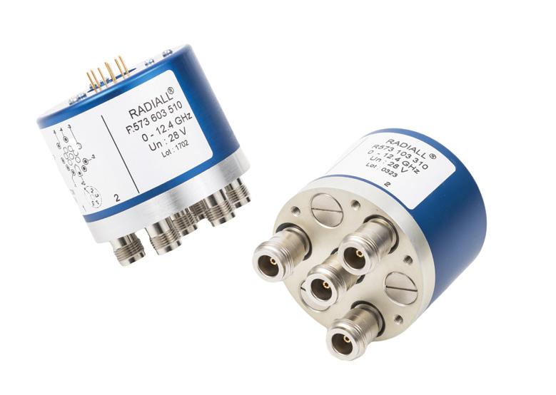
Radiall's R573 and R574 multi-throw coaxial switches are offered in many configurations (over 40,000 possible combinations), including terminated and non-terminated options. Radiall offers reliable products, with shorter delivery times and competitive pricing. Excellent typical RF performance make RAMSES switches (12.4 GHz) ideal for Automated Test Equipment (ATE) and other measurement applications. These switches are suitable for defense, industrial, and telecommunication applications �
Example of P/N: R573103600 is a SP6T N up to 12.4 GHz, Normally Open, 28 Vdc, and solder pins.
NUMBER SELECTION
SERIES PREFIX
MODEL
3: Without 50 Ω termination
4: With 50 Ω termination
RF CONNECTORS
0: N up to 3 GHz [10]
1: N up to 12 4 GHz [8 & 10]
2: BNC up to 3 GHz [3 & 4]
5: TNC up to 3 GHz [3 & 4]
6: TNC up to 12 4 GHz [3 & 4]
TYPE
0: Normally open
1: Normally open I + C
2: Latching
3: Latching + I.C.
4: Latching + S.C.O. [1 & 3]
5: Latching + S.C.O. + I.C. [1 & 3]
8: Latching + S.C.O. + A.R. [1]
9: Latching + S.C.O. + I.C. + A.R. [1]
Notes
I.C.: Indicator contact / S.C.O. : Self Cut-Off / A.R. : Auto Reset
Standard products are equipped with negative common
1. These models are already equipped with suppression diodes
2. Latching BCD driver enables also a global reset through driver code 0000 (see BCD logic coding page 1-13)
3. Available only up to 6 positions
4. Model "3" only
5. Available only for type 0, 1, 2 and 3
ACTUATOR TERMINALS
0: Solder pins
5: D-Sub connector
OPTIONS [11]
0: Without option
1: Positive common [5]
2: Compatible TTL driver [1, 7 & 9]
3: With suppression diodes
4: With suppression diodes and positive common [5]
8: BCD TTL driver compatible [1, 2, 6 & 7]
NUMBER OF POSITIONS
3: 3 positions
4: 4 positions
5: 5 positions
6: 6 positions
8: 8 positions
0: 10 positions
2: 12 positions
ACTUATOR VOLTAGE
2: 12 Vdc
3: 28 Vdc
6. Available only with type 0, 1, 8 and 9
7. Polarity is not relevant to application for switches with TTL driver
8. 8 to 12 positions are available only up to 8 GHz
9. From 8 to 12 positions, this option is only available with type 0, 1, 8 and 9
10. From 8 to 12 positions, this connector is only available without 50 Ω termination
11. For precisions see availabilty of options chart page 5-27
5-26 | SPNT SIMPLIFICATION IS OUR INNOVATION Visit www.radiall.com for more information
R57 RAMSES Series
PART
GENERAL SPECIFICATIONS
Type 2, 3, 4 and 5:
Latching models have a RESET pin which commands the reset of all positions. This command should be used before switching from one position to another. If not, two positions will be set at the same time.
Note: During the RESET operation, the global current and the nominal operating current are multiplied by the number of positions.
Type 8, 9:
Latching models with AUTOMATIC RESET are available; these products have an internal SET/RESET circuit which automatically resets all the non-selected positions and sets the desired position. This option simplifies the use of latching switches by suppressing the RESET command in switching sequence.
An electronic circuit supplies successively groups of 2, 3 or 4 actuators, in order to limit the maximum current. The current with this option is the total current of 2, 3 or 4 reset coils in the same time (see table below).
Example: During the AUTOMATIC RESET operation, at 28 Vdc, 4 position switch has a temporary consumption of only 250 mA, during 40 ms maximum.
SWITCHING SEQUENCE
FOR SP10 TO 12T FOR SP6 TO 8T
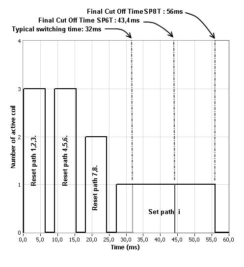
n = number of positions
OPERATING TOTAL CURRENT AT 23 °C (MA) SPNT LATCHING
NUMBER OF POSITIONS 12 VOLTS 28 VOLTS
3 to 4 320 × n
5 to 8
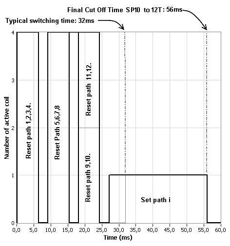
Availability of options according to both type and number of positions.
SPNT | 5-27 SIMPLIFICATION IS OUR INNOVATION Visit www.radiall.com for more information
TYPE NUMBERS OF POSITIONS AVAILABLE OPTIONS 0 or 1 3 to 12 0 - 1 - 2 - 3 - 4 - 8 2 or 3 3 to 6 0 - 1 - 2 - 3 - 4 8 to 12 0 - 1 - 3 - 4 4 or 5 3 to 6 0 - 2 8 to 12 N/A 8 or 9 3 to 12 0 - 2 - 8
MANUAL RESET AUTOMATIC RESET MANUAL RESET AUTOMATIC RESET
125
250
640
× n
320
n 960 125 × n 375
×
320
n 1280 125 × n 500
9 to 12
×
RAMSES Series
GENERAL SPECIFICATIONS
See table on previous page
See Power Rating Chart page 1-13
Indicator
Switching time (max) ms 15 ms For automatic reset models: SP3T to SP6T = 40 ms SP8T to SP12T = 50 ms
Life (min)
Non-terminated SP3 to 6T (R573 series) 2 million cycles
Terminated SP3 to 6T (R574 series)
SP8 to 12T (all models)
Connectors N - TNC - BNC
Actuator terminals
Solder pins or male 25 pin D-Sub connector
Operating temperature range -40 ºC to +85 ºC
Storage temperature range -55 ºC to +85 ºC
Vibration (MIL STD 202, method 204D, cond C) 10 - 2,000 Hz, 10 g operating
Shock (MIL STD 202, method 213B, cond �C) 50 g/1 ms, 1/2 sine operating
RF PERFORMANCE
N - TNC - BNC Connector
POSITIONS
Notes
See page 5-29 for typical RF performance.
5-28 | SPNT SIMPLIFICATION IS OUR INNOVATION Visit www.radiall.com for more information
FREQUENCY RANGE GH z V.S.W.R. (MAX) INSERTION LOSS (MAX) d B ISOLATION (MIN) dB IMPEDANCE Ω 3 to 6 DC - 12 � 4 DC - 3 1 20 0 20 80 50 3 - 8 1� 35 0� 35 70 8 - 12 4 1 50 0 50 60 8 & 10 DC - 8 DC - 3 1 30 0 30 80 3 - 8 1 50 0 50 70 12 DC - 8 DC - 3 1 35 0 50 70 3 - 8 1 70 1 00 60
NUMBER OF
MODE NORMALLY OPEN LATCHING Nominal operating voltage (across operating temperature) Vdc 12 (10 2/13) 28 (24/30) 12 (10 2/13) 28 (24/30) Coil resistance (+/-10%) Ω 47 5 275
Nominal operating current at 23 ºC mA 250 102
power
TTL input High Level 2 2 to 5 5 V
Option) 3 5 to 5 5 V (BCD Option) 800 μA max 5.5 volts Low Level 0 to 0 8 V (TTL Option) 0 to 1 5 V (BCD Option) 20 μA max 0.8 volts
OPERATING
Average
(TTL
rating 1 W/30 V/100 mA
RAMSES Series
RAMSES Series
R573 & R574 TYPICAL PERFORMANCE
Example: SP6T N up to 12.4 GHz
INSERTION LOSS & ISOLATION
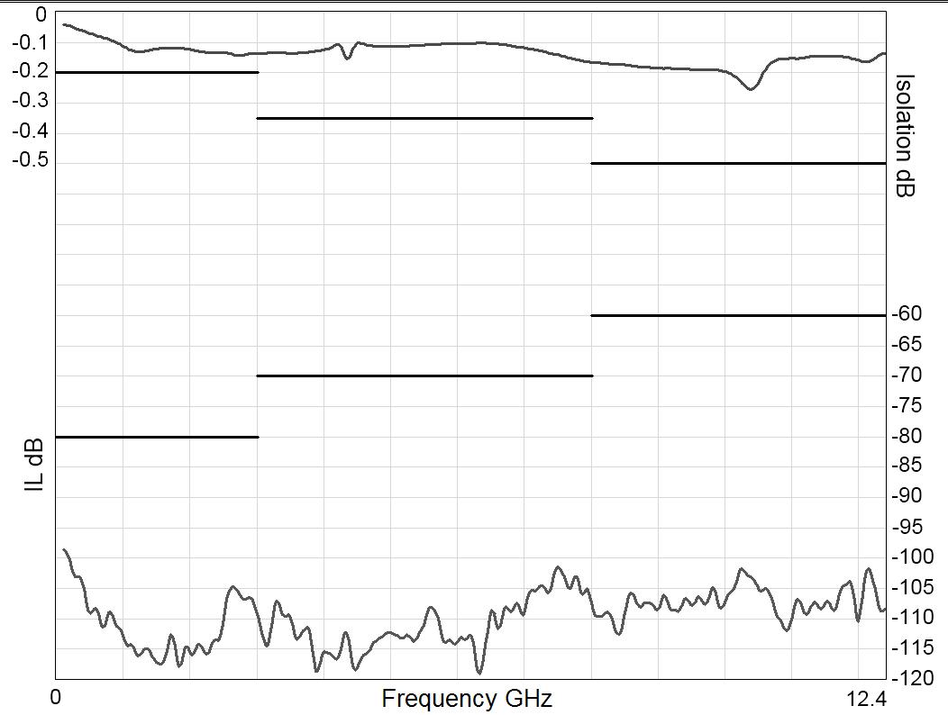
Frequency (GHz)
Example: SP6T TNC up to 12.4 GHz
INSERTION LOSS & ISOLATION
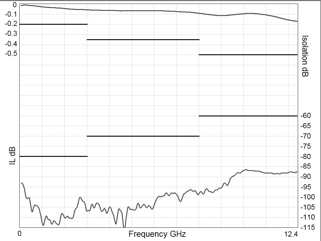
Frequency (GHz)
Example: SP8T up to 8 GHz
INSERTION LOSS & ISOLATION
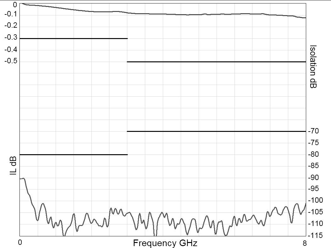
Frequency (GHz)
V.S.W.R
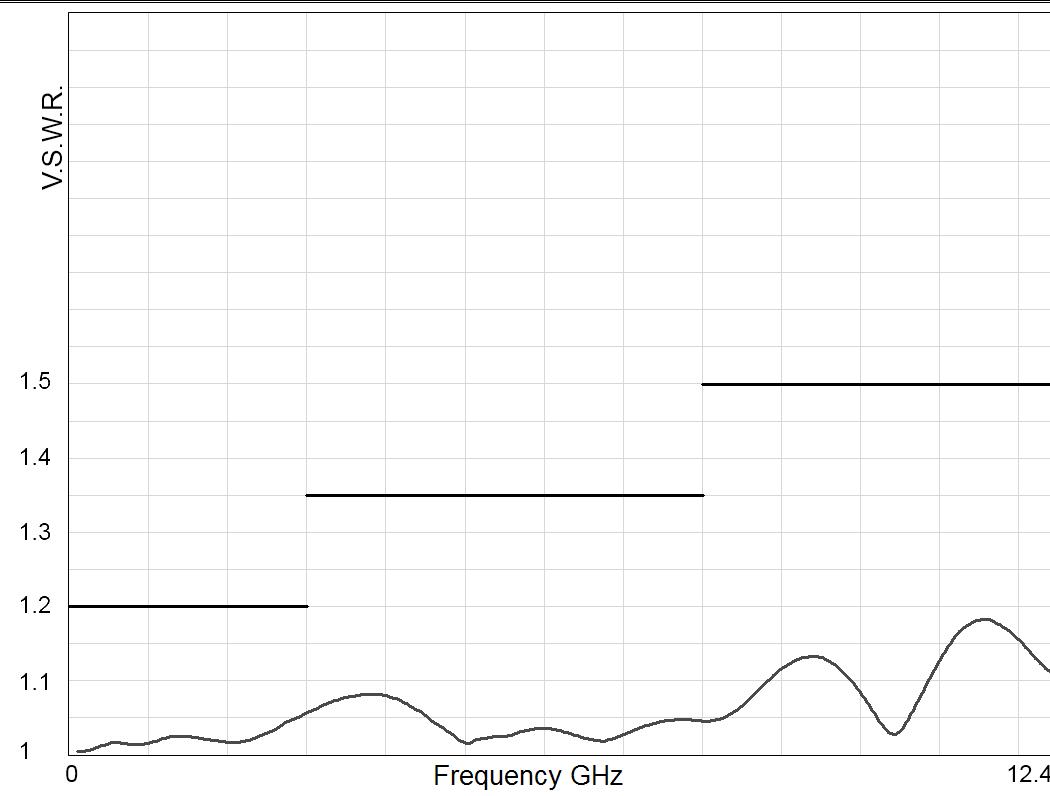
Frequency (GHz)
V.S.W.R
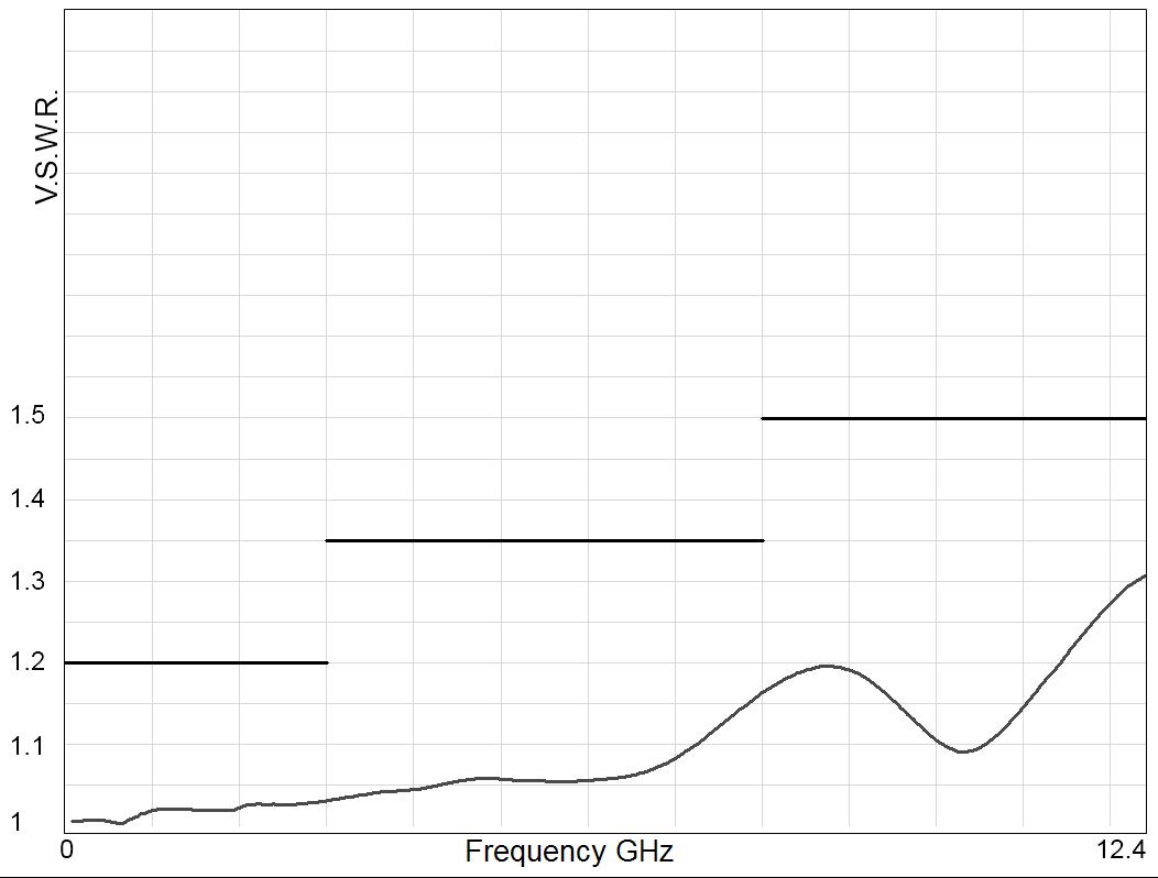
Frequency (GHz)
V.S.W.R
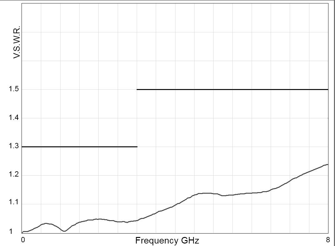
Frequency (GHz)
SPNT | 5-29 SIMPLIFICATION IS OUR INNOVATION Visit www.radiall.com for more information
RAMSES Series
TYPICAL OUTLINE DRAWINGS
Terminated or non-terminated 3 to 12 positions
8 POSITIONS 8 GHz WITH SOLDER PINS MODEL
Notes All dimensions are in millimeters [inches].
[INCHES])
5 [0 748]
5 [0 472]
� 5 [0� 472]
10 POSITIONS 8 GHz WITH D-SUB CONNECTOR MODEL
5-30 | SPNT SIMPLIFICATION IS OUR INNOVATION Visit www.radiall.com for more information TYPE B MAX
SOLDER PINS D-SUB CONNECTOR Type 0
option 0
1
3
4 56 [2 205] 66 [2 598] Type 0 - 1
option 2 or 8 71 [2 80] 71 [2 80] Type 4 - 5
8
9 with option 0 - 1
2
8 NUMBER OF POSITIONS C DIAMETER D DIAMETER E DIAMETER F 3 - 6 54 [2 �126] 44 �7 [1�732] 63 � 5 [2 � 480] 6 holes M4/60° 8 67 7 [2 738] 58 9 [2 283] 76 2 [2 99] 4 holes M4/90° 10 88 9 [3 465] 76 2 [2 992] 101 6 [3 976] 5 holes M4/72° 12 67 7 [2 738] 101 6 [3 976] 127 [5] 6 holes M4/60°
N 19
BNC 12
TNC 12
(MM [INCHES])
- 1 - 2 or 3 with
-
-
or
- 2 or 3 with
-
or
-
or
CONNECTORS A MAX (MM
RF CONNECTOR ALLOCATION FOR SPNT SERIES
ALL CONNECTORS
Connectors A: 1.6/5.6, QMA, SMA, SMA 2.9, 2.4 mm
Other Connectors: N, BNC, TNC
SPNT 3 WAYS
NON-TERMINATED VERSION
Up to 40 GHz models Without option Connectors A (except 2 � 4 mm)
SPNT 4 WAYS
Up to 40 GHz models With option Connectors A and other connectors (except 2 � 4 mm)
TERMINATED VERSION
Up to 18 GHz models Connectors A and other connectors (except 2 � 4 mm)
GHz and 40 GHz models with SMA - SMA 2 �9
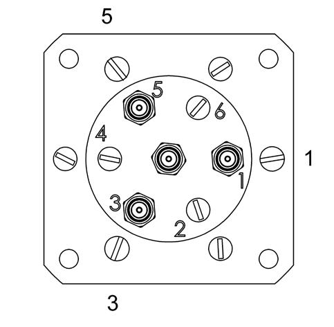
NON-TERMINATED VERSION TERMINATED VERSION
Up to 50 GHz models Without option Connectors A
Up to 50 GHz models With option Connectors A and other connectors
Up to 18 GHz models Connectors A and other connectors (except 2 4 mm)
5
40
and 50
models with SMA - SMA 2.92 4 mm
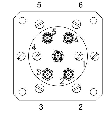
SPNT 5 WAYS
NON-TERMINATED VERSION
Up to 40 GHz models Without option Connectors A (except 2 4 mm)
Up to 40 GHz models With option Connectors A and other connectors (except 2 4 mm)
TERMINATED VERSION
Up to 18 GHz models Connectors A and other connectors (except 2 4 mm) 26.5 GHz and 40 GHz models with SMA - SMA 2 9
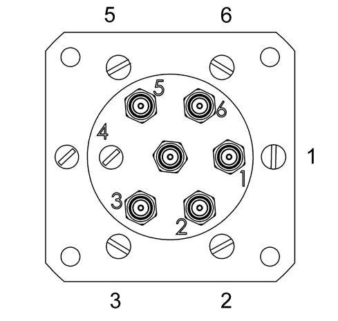
SPNT | 5-31 SIMPLIFICATION IS OUR INNOVATION Visit www.radiall.com for more information
26.5
26
GHz,
GHz
GHz
RAMSES Series
Connectors A: 1.6/5.6, QMA, SMA, SMA 2.9, 2.4 mm
Other Connectors: N, BNC, TNC
SPNT 6 WAYS
NON-TERMINATED VERSION
Up to 50 GHz models Without Option Connectors A Up to 50 GHz models With Option Connectors A and other connectors
TERMINATED VERSION
to 22 GHz models Connectors A and other connectors
and
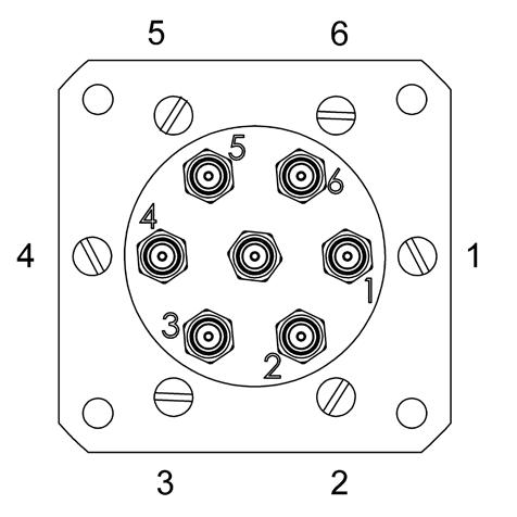
SPNT 8 WAYS
SMA and N connectors
SPNT 10 WAYS
SMA and N connectors
SPNT 12 WAYS
SMA and N connectors
5-32 | SPNT SIMPLIFICATION IS OUR INNOVATION Visit www.radiall.com for more information
26 � 5
40 GHz
50
SMA
SMA
4
Up
GHz,
GHz models with
-
2.92
mm
RAMSES
Series
Accessories SPnT & Electrical Schematics
COAXIAL SPNT - ACCESSORIES
PRINTED CIRCUIT BOARD INTERFACE CONNECTOR
A printed circuit board interface connector (ordered separately) has been designed for easy mounting on terminals
For SPnT model R573 and R574 series: Radiall part number: R599 906 000 for 3 to 6 positions, R599 908 000 for 8 positions, R599 900 000 for 10 positions, and R599 902 000 for 12 positions.
R599906000
R599902000
R599908000
R599900000
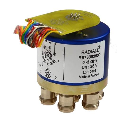
SPNT | 5-33 SIMPLIFICATION IS OUR INNOVATION Visit www.radiall.com for more information
Accessories SPnT & Electrical Schematics
Mounting Bracket
Two different metal brackets have been designed for an easy mechanical mounting of our SPnT switches with a circular flange for customer installation. These brackets must be ordered separately and assembled according to our recommended process on the Technical Data Sheets
MODEL WITH SCREWS (R599320000)
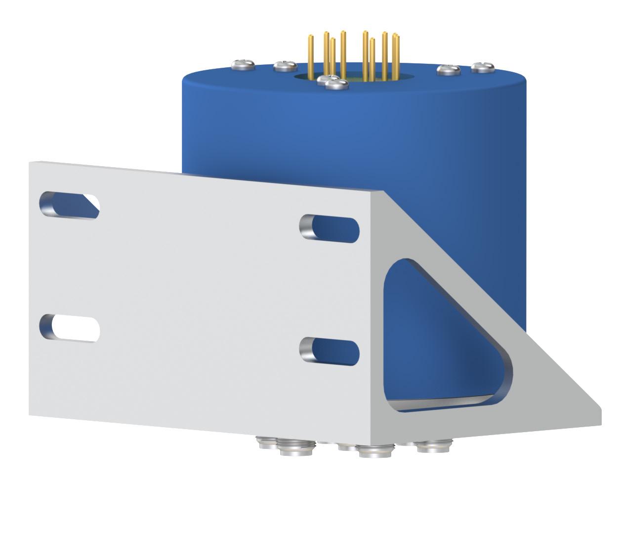
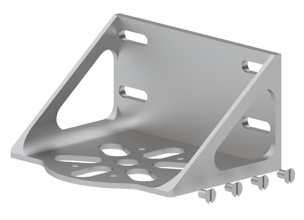
Notes
All dimensions are in millimeters [inches]. For assembling process please see Technical Data Sheet.
5-34 | SPNT SIMPLIFICATION IS OUR INNOVATION Visit www.radiall.com for more information
Accessories SPnT & Electrical Schematics
MODEL WITH ADHESIVE (R59992X000)
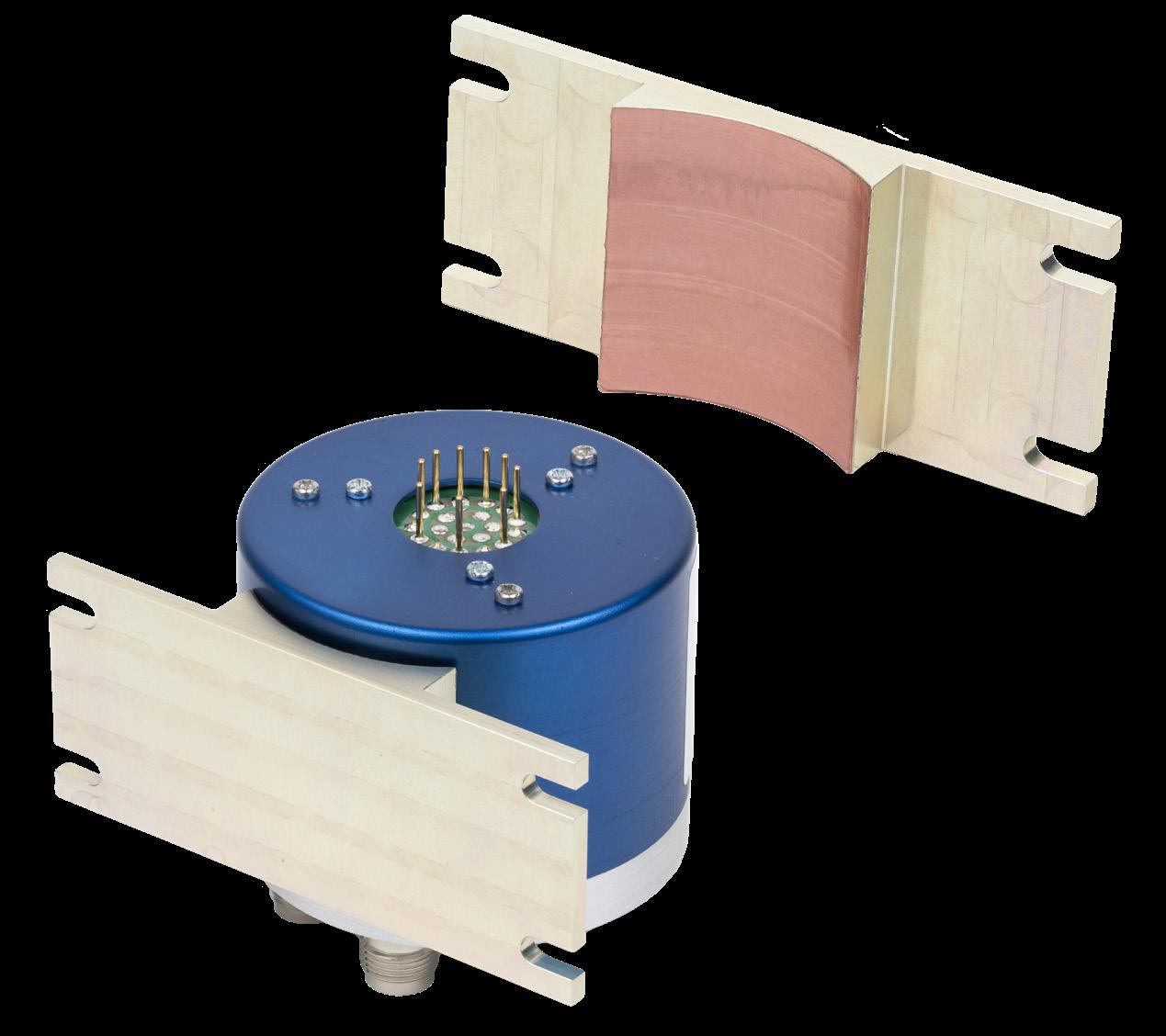
Protective adhesive tape surface
GENERAL TOLERANCES: ±0.5 MM [0.02]
Notes
All dimensions are in millimeters [inches]. This model can also be mounted on our SPnT switches with a square flange. For adhesive bonding process please see Technical Data Sheet.
SPNT | 5-35 SIMPLIFICATION IS OUR INNOVATION Visit www.radiall.com for more information
Accessories SPnT & Electrical Schematics
FOR MODELS WITH CONNECTORS SMA, QMA, SMA 2.9, 2.4 MM, DIN 1.6/5.6
NUMBER OF POSITIONS
3 to 6 positions
8 positions
10 positions
12 positions
FOR MODELS WITH CONNECTORS N, TNC, BNC
NUMBER OF POSITIONS
3 to 6 positions
8 to 12 positions
MOUNTING SQUARE FLANGE
MODEL PART NUMBER
R573 series
R574 series
R573 series
R574 series
R573 series
R574 series
R573 series
R574 series
MODEL
R573 series
R574 series
R573 series
R574 series
R599320000
R599920000
R599920000
R599921000
R599922000
PART NUMBER
R599921000
Not Available
A square flange has been designed for easy mechanical mounting of our SPnT switches with a circular flange for customer installation. These flanges must be ordered separately (similar to the mounting bracket) and assembled according to our recommended process on the following page.
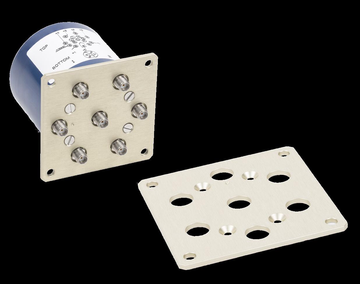
TYPICAL OUTLINE DRAWING
5-36 | SPNT SIMPLIFICATION IS OUR INNOVATION Visit www.radiall.com for more information
Accessories SPnT & Electrical Schematics
MATERIAL: ALUMINIUM WITH CR3 PASSIVATION
PART
FOR MODELS WITH CONNECTORS SMA, QMA, SMA 2.9, 2.4 MM, DIN 1.6/5.6
R573 series
3 to 6 positions
R574 series R599311000 R599309000 8 positions
positions
positions
FOR MODELS WITH CONNECTORS N, TNC, BNC
NUMBER OF POSITIONS
3 to 6 positions
D-SUB CONNECTOR LOCATION
R573 & R574
3 to 6 positions
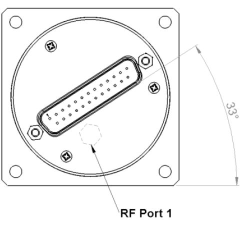
Notes
R573 series
R574 series
R573 series
R574 series
R573 series
R574 series
R573 series R599315000
R574 series
R573 & R574 10 positions
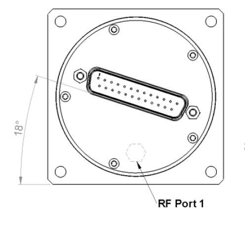
All dimensions are in millimeters [inches]. For assembling process please see Technical Data Sheet.
R573 & R574 8 & 12 positions
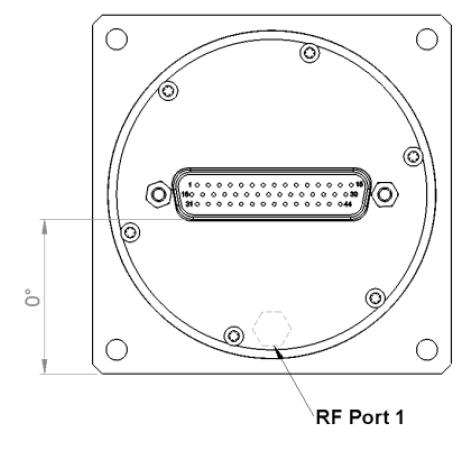
SPNT | 5-37 SIMPLIFICATION IS OUR INNOVATION Visit www.radiall.com for more information
RADIALL
NUMBER A (MM [INCHES]) B (MM [INCHES]) C (MM [INCHES]) D (MM [INCHES]) E (MM [INCHES]) R599 308 000 57�15 [2 � 244] 45 �75 [1�772] 27 [1�063] 2 [0�079] 9 [0� 354] R599 309 000 57 15 [2 244] 45 75 [1 772] 44 70 [1 732] 2 [0 079] 9 [0 354] R599 310 000 63 45 [2 480] 53 45 [2 087] 27 [1 063] 2 [0 079] 9 [0 354] R599 311 000 63 45 [2 480] 53 45 [2 087] 44 70 [1 732] 2 [0 079] 9 [0 354] R599 312 000 63 45 [2 480] 53 45 [2 087] 44 70 [1 732] 2 [0 079] 9 [0 354] R599 313 000 69 80 [2 717] 59 80 [2 323] 44 70 [1 732] 2 [0 079] 9 [0 354] R599 314 000 74 �60 [2 �913] 64 �60 [2 � 520] 55 � 88 [2 �165] 2 [0�079] 9 [0� 354] R599 315 000 71 10 [2 795] 60 30 [2 362] 44 70 [1 732] 3 [0 118] 16 20 [0 630]
NUMBER
MODEL PART NUMBER
OF POSITIONS
R599310000
R599308000
R599312000
10
R599313000
12
R599314000
MODEL PART NUMBER
COAXIAL SPNT - ELECTRICAL SCHEMATICS
R573 - R574 SERIES
NORMALLY OPEN Accessories SPnT & Electrical Schematics
WITHOUT OPTION
R573-0--0- / R574-0--0-

WITH SUPPRESSION DIODES
R573-0--3- / R574 -0- -3-
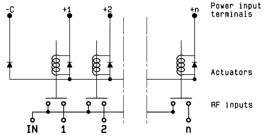
WITH TTL DRIVER (SUPRESSION DIODES ARE INCLUDED)
R573-0--2- / R574 -0- -2-
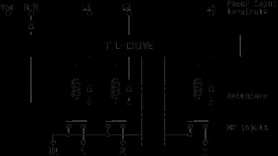
WITH INDICATOR CONTACT
R573-1--0- / R574 -1- -0-

WITH SUPPRESSION DIODES & INDICATOR CONTACT
R573-1--3- / R574 -1- -3-
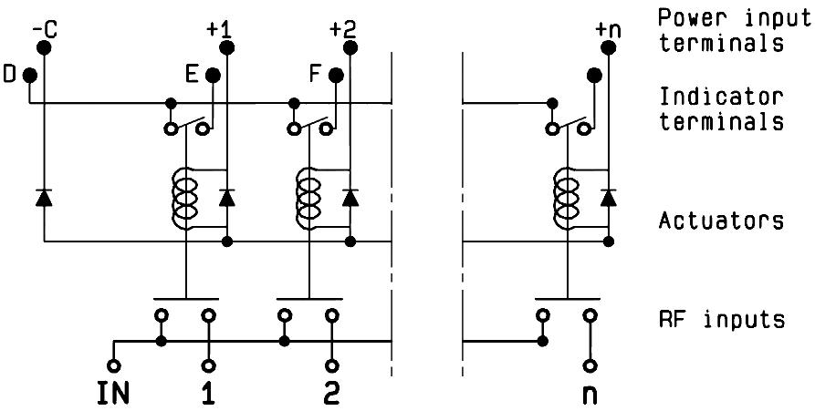
WITH TTL DRIVER & INDICATOR CONTACT (SUPRESSION DIODES ARE INCLUDED)
R573-1--2- / R574 -1- -2-
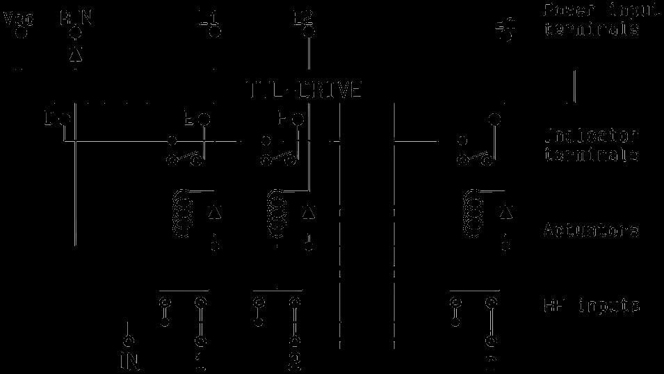
5-38 | SPNT SIMPLIFICATION IS OUR INNOVATION Visit www.radiall.com for more information
COAXIAL SPNT - ELECTRICAL SCHEMATICS (CONTINUED)
R573 - R574 SERIES
NORMALLY OPEN Accessories SPnT & Electrical Schematics
WITH BCD DRIVER, TTL COMPATIBLE (SUPPRESSION DIODES ARE INCLUDED)
R573-0--8- / R574-0--8-
WITH POSITIVE COMMON
R573-0--1- / R574 -0- -1-
WITH POSITIVE COMMON AND SUPPRESSION DIODES
R573-0--4- / R574 -0- -4-

WITH BCD DRIVER, TTL COMPATIBLE & INDICATOR CONTACT (SUPPRESSION DIODES ARE INCLUDED)
R573-1--8- / R574 -1- -8-
WITH POSITIVE COMMON AND INDICATOR CONTACT
R573-1--1- / R574 -1- -1-

WITH POSITIVE COMMON, SUPPRESSION DIODES & INDICATOR CONTACT
R573-1--4- / R574 -1- -4-
SPNT | 5-39 SIMPLIFICATION IS OUR INNOVATION Visit www.radiall.com for more information
Accessories SPnT & Electrical Schematics
COAXIAL SPNT - ELECTRICAL SCHEMATICS
R573 - R574 SERIES
LATCHING
WITHOUT OPTION
R573-2--0- / R574-2--0-
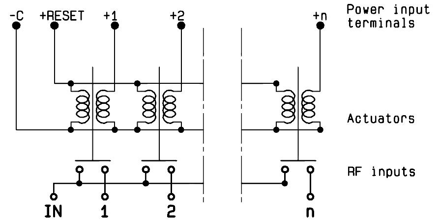
WITH SUPPRESSION DIODES
R573-2--3- / R574 -2- -3-

WITH TTL DRIVER (SUPRESSION DIODES ARE INCLUDED)
R573-2--2- / R574 -2- -2-

WITH INDICATOR CONTACT
R573-3--0- / R574 -3- -0-
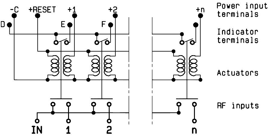
WITH SUPPRESSION DIODES AND INDICATOR CONTACT
R573-3--3- / R574 -3- -3-

WITH TTL DRIVER & INDICATOR CONTACT (SUPRESSION DIODES ARE INCLUDED)
R573-3--2- / R574 -3- -2-
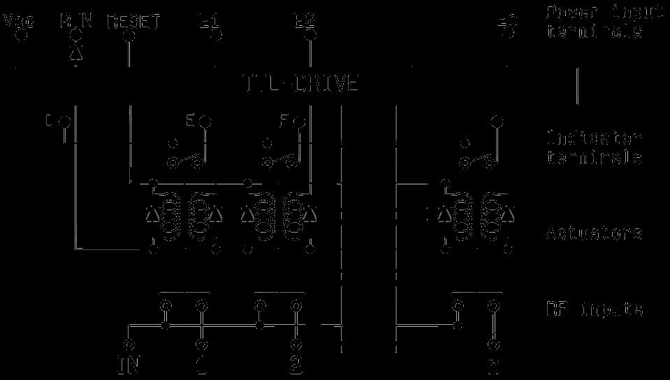
5-40 | SPNT SIMPLIFICATION IS OUR INNOVATION Visit www.radiall.com for more information
Accessories SPnT & Electrical Schematics
COAXIAL SPNT - ELECTRICAL SCHEMATICS (CONTINUED)
R573 - R574 SERIES
LATCHING
WITH CUT-OFF (SUPPRESSION DIODES ARE INCLUDED)
R573-4--0- / R574-4--0-
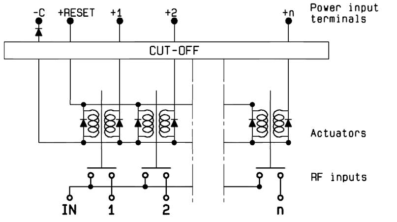
WITH CUT-OFF & AUTO REST (SUPPRESSION DIODES ARE INCLUDED)
R573 -8- -0- / R574 -8- -0-
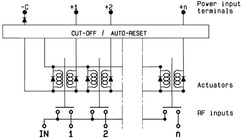
WITH TTL DRIVER AND CUT-OFF (SUPPRESSION DIODES ARE INCLUDED)
R573-4--2- / R574 -4- -2-
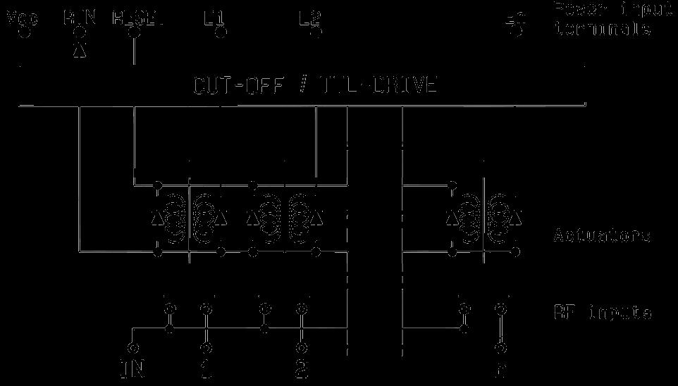
WITH CUT-OFF AND INDICATOR CONTACT (SUPPRESSION DIODES ARE INCLUDED)
R573-5--0- / R574 -5- -0-
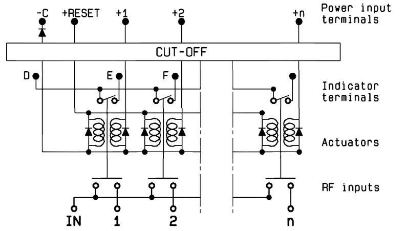
WITH CUT-OFF, AUTO REST & INDICATOR CONTACT (SUPPRESSION DIODES ARE INCLUDED)
R573-9--0- / R574 -9- -0-
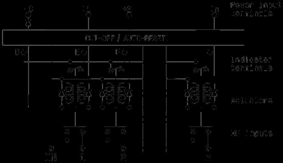
WITH TTL DRIVER, CUT-OFF & INDICATOR CONTACT (SUPPRESSION DIODES ARE INCLUDED)
R573-5--2- / R574 -5- -2-
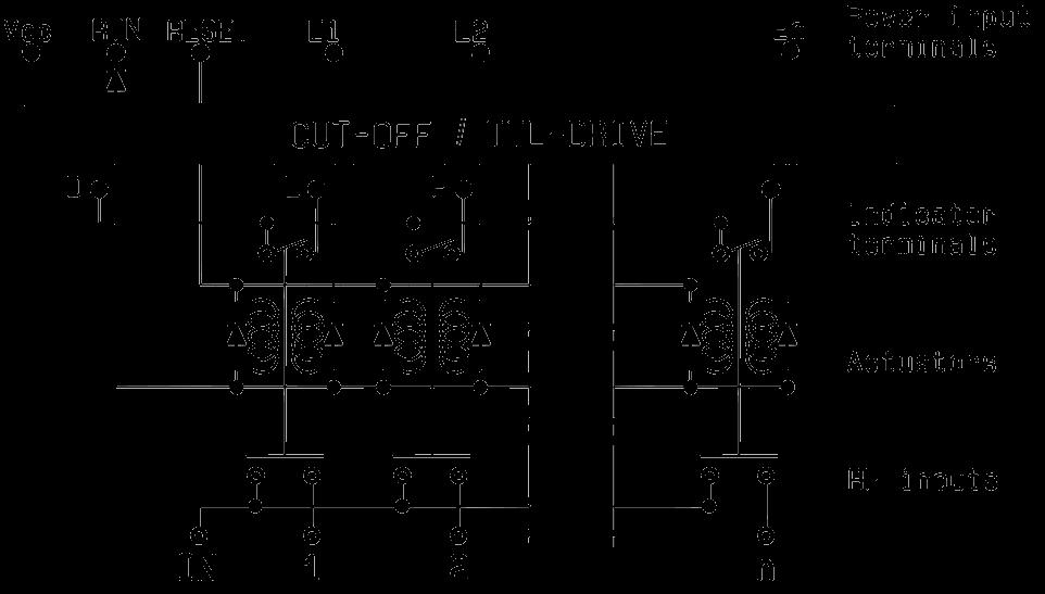
SPNT | 5-41 SIMPLIFICATION IS OUR INNOVATION Visit www.radiall.com for more information
Accessories SPnT & Electrical Schematics
COAXIAL SPNT - ELECTRICAL SCHEMATICS (CONTINUED)
R573 - R574 SERIES
LATCHING
WITH TTL DRIVER, CUT-OFF & AUTO RESET (SUPPRESSION DIODES ARE INCLUDED)
R573-8--2- / R574-8--2-
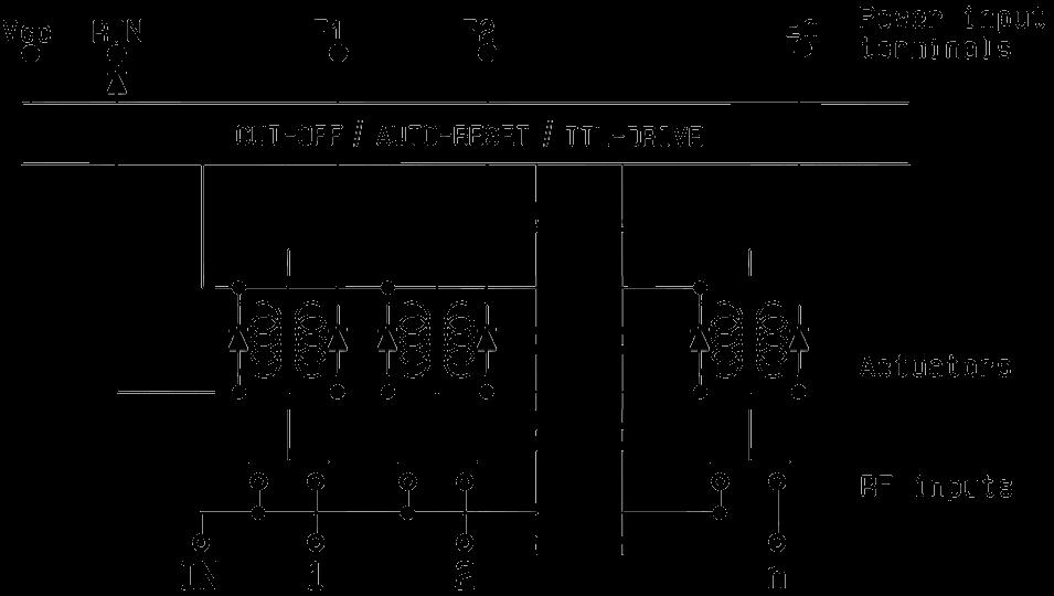
WITH CUT-OFF, FORCE OR AUTO RESET, BCD DRIVER, TTL COMPATIBLE (SUPPRESSION DIODES ARE INCLUDED)
R573-8--8- / R574 -8- -8-
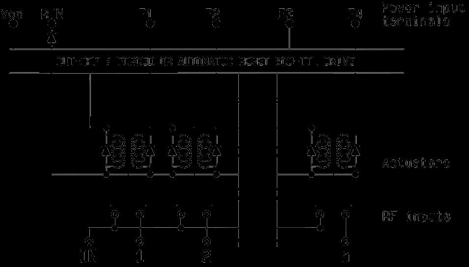
WITH POSITIVE COMMON
R573-2--1- / R574 -2- -1-
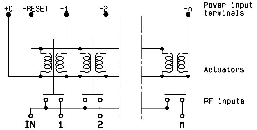
WITH TTL DRIVER, CUT-OFF, AUTO RESET & INDICATOR CONTACT (SUPPRESSION DIODES ARE INCLUDED)
R573-9--2- / R574 -9- -2-
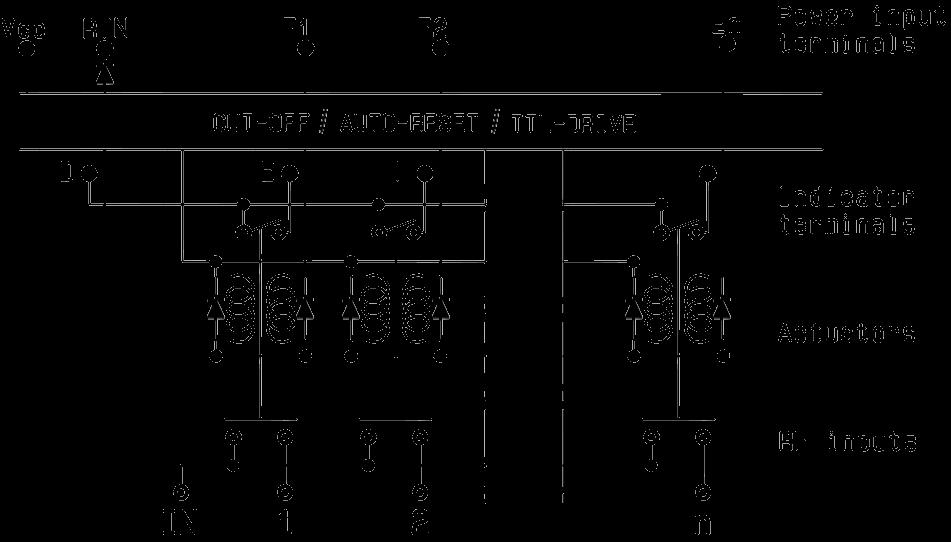
WITH CUT-OFF, FORCE OR AUTO RESET, BCD DRIVER, TTL COMPATIBLE & INDICATOR CONTACT (SUPPRESSION DIODES ARE INCLUDED)
R573-9--8- / R574 -9- -8-
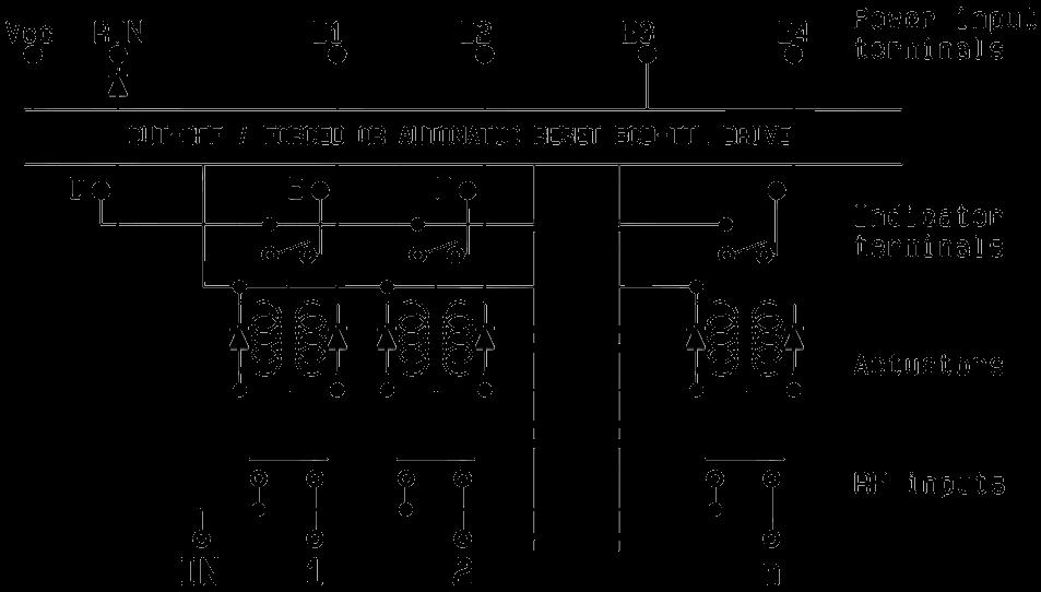
WITH POSITIVE COMMON & INDICATOR CONTACT (SUPRESSION DIODES ARE INCLUDED)
R573-3--1- / R574 -3- -1-
5-42 | SPNT SIMPLIFICATION IS OUR INNOVATION Visit www.radiall.com for more information
Accessories SPnT & Electrical Schematics
COAXIAL SPNT - ELECTRICAL SCHEMATICS (CONTINUED)
R573 - R574 SERIES
LATCHING
WITH POSITIVE COMMON & SUPPRESSION DIODES (SUPPRESSION DIODES ARE INCLUDED)
R573-2--4- / R574-2--4-
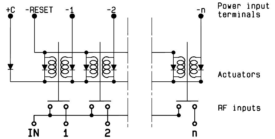
WITH POSITIVE COMMON, CUT-OFF, AUTO RESET
R573-8--1- / R574-8--1-
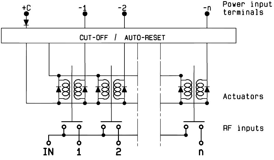
USB SERIES
NORMALLY OPEN WITH INDICATOR CONTACT
R573-11-01 / R574-11-01
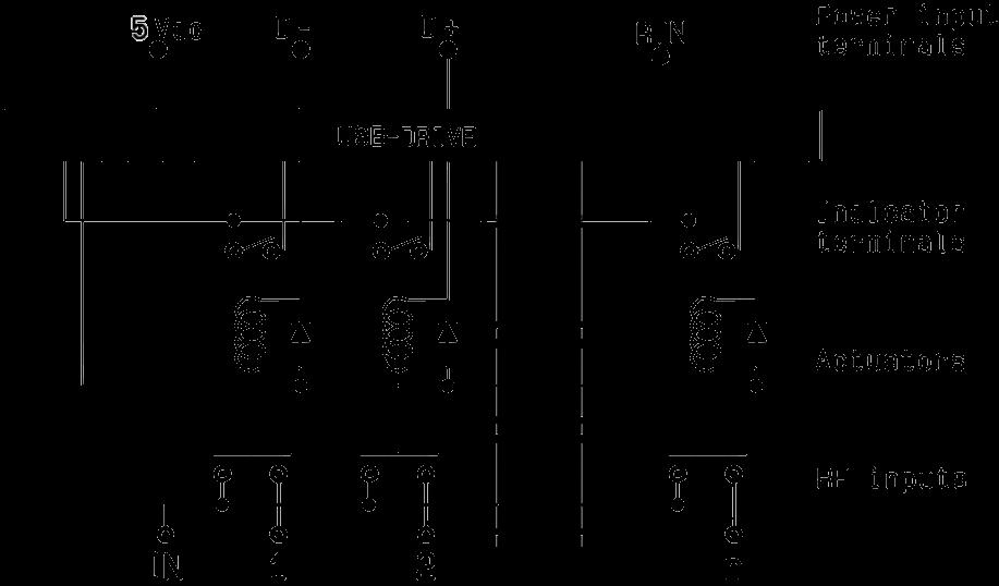
WITH POSITIVE COMMON, SUPPRESSION DIODES & INDICATOR CONTACT
R573-3--4- / R574 -3- -4-
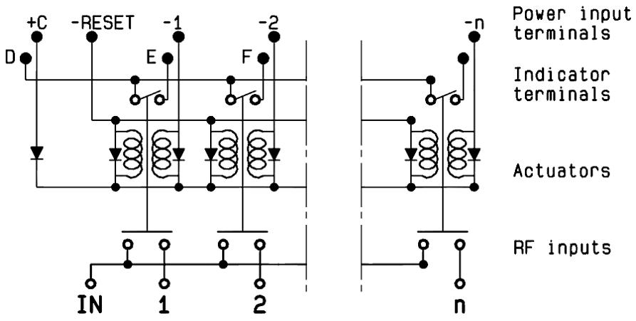
WITH POSITIVE COMMON, CUT-OFF, AUTO RESET & INDICATOR CONTACT
R573-9--1- / R574-9--1-
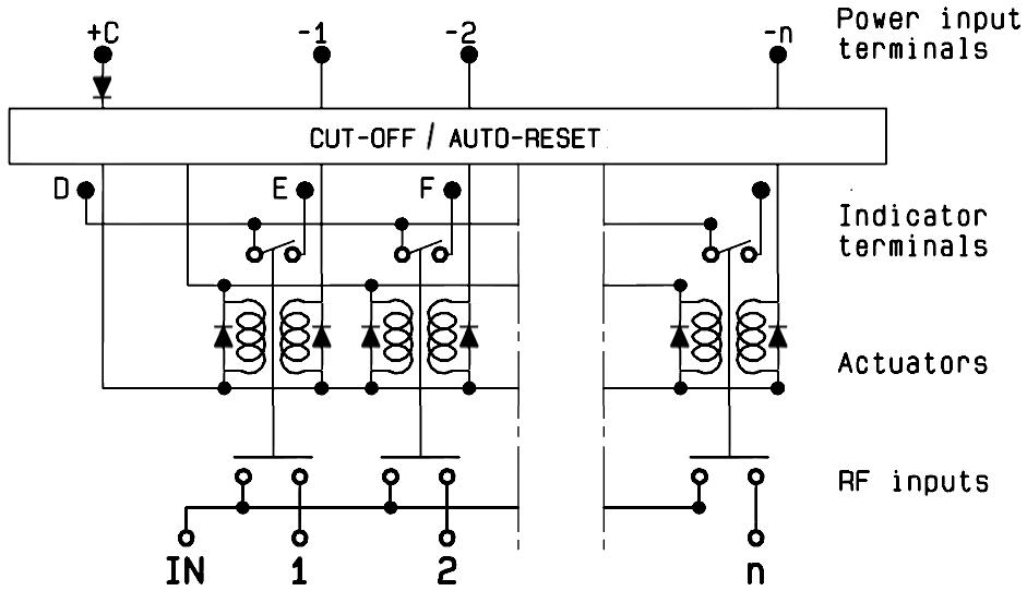
SPNT | 5-43 SIMPLIFICATION IS OUR INNOVATION Visit www.radiall.com for more information
HIGH PERFORMANCE MULTIPORT SWITCHES
SPNT UP TO 40 GHz
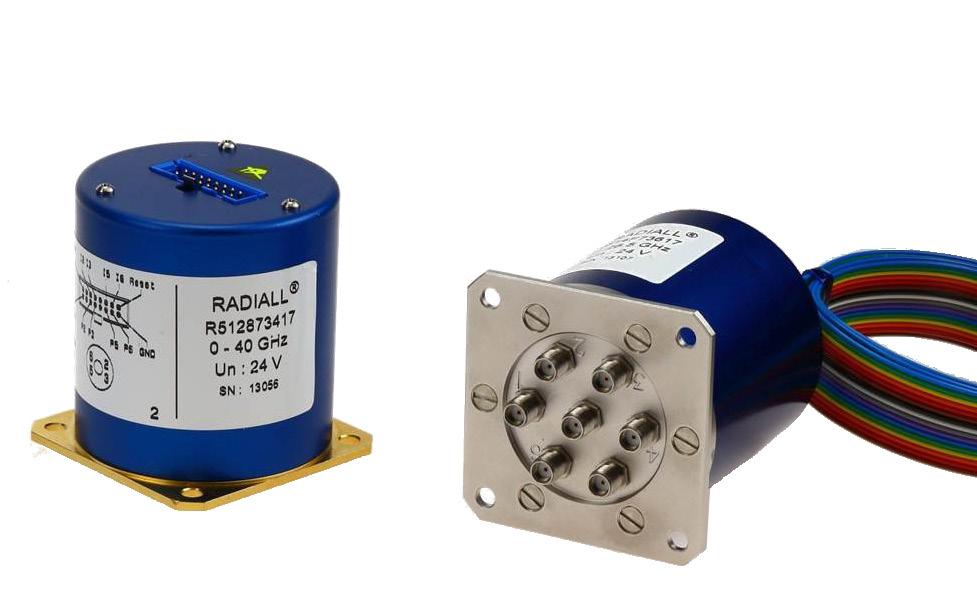
Radiall’s TITANIUM switches are optimized to perform at a high level over an extended life cycle. With outstanding RF performance, and a guaranteed insertion loss repeatability of 0.03 dB over a life span of 2.5 million switching cycles, Radiall's TITANIUM switches are a perfect solution for automated test and measurement equipment, as well as signal monitoring devices.
Example of P/N: R514F73617 is a SP6T SMA up to 26.5 GHz, Latching, Indicators, Self cut-off, Auto-Reset, 24 Vdc and HE10 receptacle.
PART NUMBER SELECTION
SERIES PREFIX
MODEL
3: Without 50 Ω termination
4: With 50 Ω termination
RF CONNECTORS
3: SMA up to 6 GHz
4: SMA up to 20 GHz
F: SMA up to 26 � 5 GHz
8: SMA 2�9 up to 40 GHz [1]
TYPE
7: Latching + Self cut-off + Auto Reset + Indicators
ACTUATOR VOLTAGE
3: 24 Vdc
NUMBER OF POSITIONS
4: 4 positions
6: 6 positions
OPTIONS *
1: Positive common (without TTL)
2: TTL/5 V logic with 24 Vdc supply [2]
ACTUATOR TERMINAL
7: HE 10 receptacle, delivered with 750 mm (30 inches) ribbon cable + HE10 connector
DOCUMENTATION
-: Certificate of conformity
C: Calibration certificate
R: Calibration certificate + RF curves
Notes
1. Connector SMA 2.9 is equivalent to "K connector ®", registered trademark of Anritsu.
2. Polarity is not relevant to application for switches with TTL driver
5-44 | SPNT SIMPLIFICATION IS OUR INNOVATION Visit www.radiall.com for more information
Titanium Series
R51
GENERAL SPECIFICATIONS
OPERATING MODE LATCHING
Nominal operating voltage (across operating temperature) Vdc 24 (20/32) Coil resistance (+/-10%) Ω 120
Operating current at 23 °C mA 200
Maximum stand-by current mA 50
Average power Terminated Model All models
RF path Cold switching: See Power page 5-50 Hot switching: 1 Watt Cw
Internal terminations 1 Watt average into 50 Ω TTL input
withstanding
Indicator specifications
Minimum "OFF" resistance
Switching time (max) ms 15 Life (min) SMA 2 � 5 million cycles SMA 2 9 1 million cycles
Connectors SMA - SMA 2 9
Actuator terminals HE10 ribbon receptacle
Weight (max) g 230
ENVIRONMENTAL SPECIFICATIONS
Operating temperature range -25 ºC to +75 ºC
Storage temperature range -55 ºC to +85 ºC
Temperature cycling (MIL-STD-202, Method 107D, Cond.A) -55 ºC to +85 ºC (10 cycles)
Vibration (MIL STD 202, Method 204D, Cond D) 10 - 2,000 Hz, 10 g - operating
Shock (MIL STD 202, Method 213B, Cond C) 50 g/6 ms, 1/2 sine - operating
Moisture resistance (MIL STD 202, Method 106E, Cond � E) 65 ºC, 95% RH, 10 days
Altitude storage (MIL STD 202, Method 105C, Cond.B) 50,000 ft (15,240 meters)
RFI (MIL STD 1344, Method 3008 or IEC 61726) 55 dB at 20 GHz Magnetic field < 5.10-5 gauss at 1 meter
SPNT | 5-45 SIMPLIFICATION IS OUR INNOVATION Visit www.radiall.com for more information
High
1 4
max
Max Low
-
level 3 to 7 V
mA
at Vcc =
level 0 to 0� 8 Volts
Maximum
voltage 60 V Maximum current capacity 150 mA Maximum "ON" resistance 2.5 Ω
100 MΩ
Titanium Series
RF PERFORMANCE
TYPICAL
INSERTION LOSS & ISOLATION
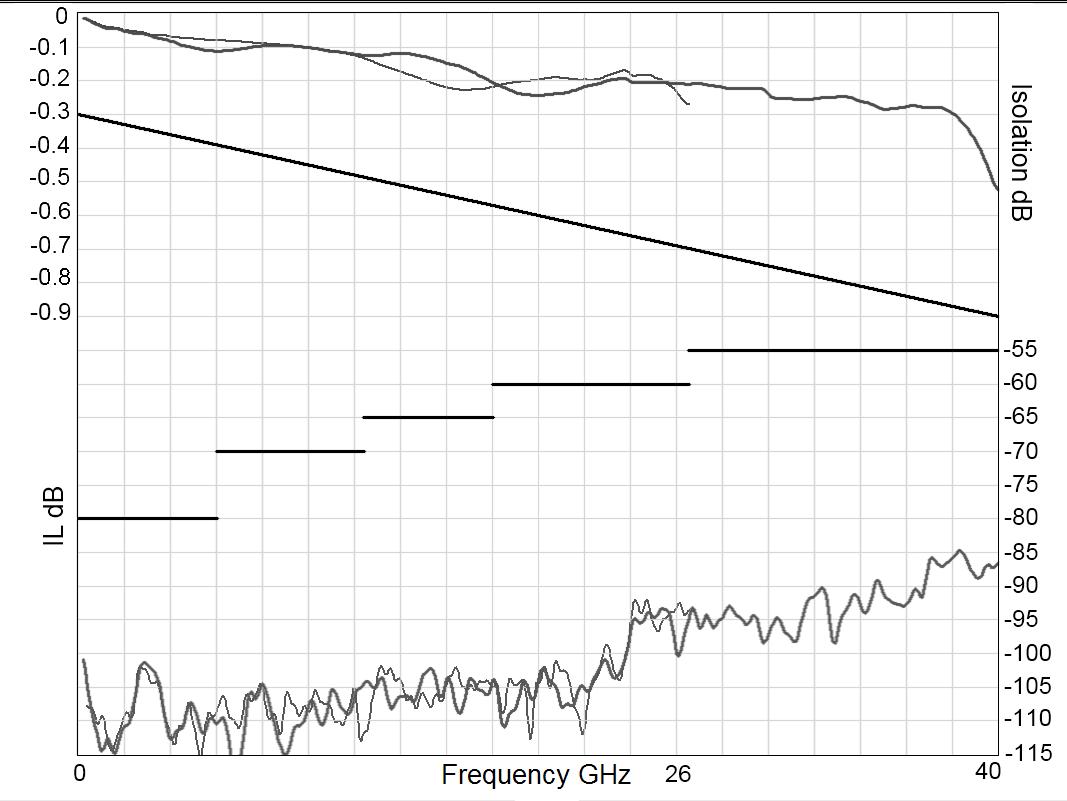
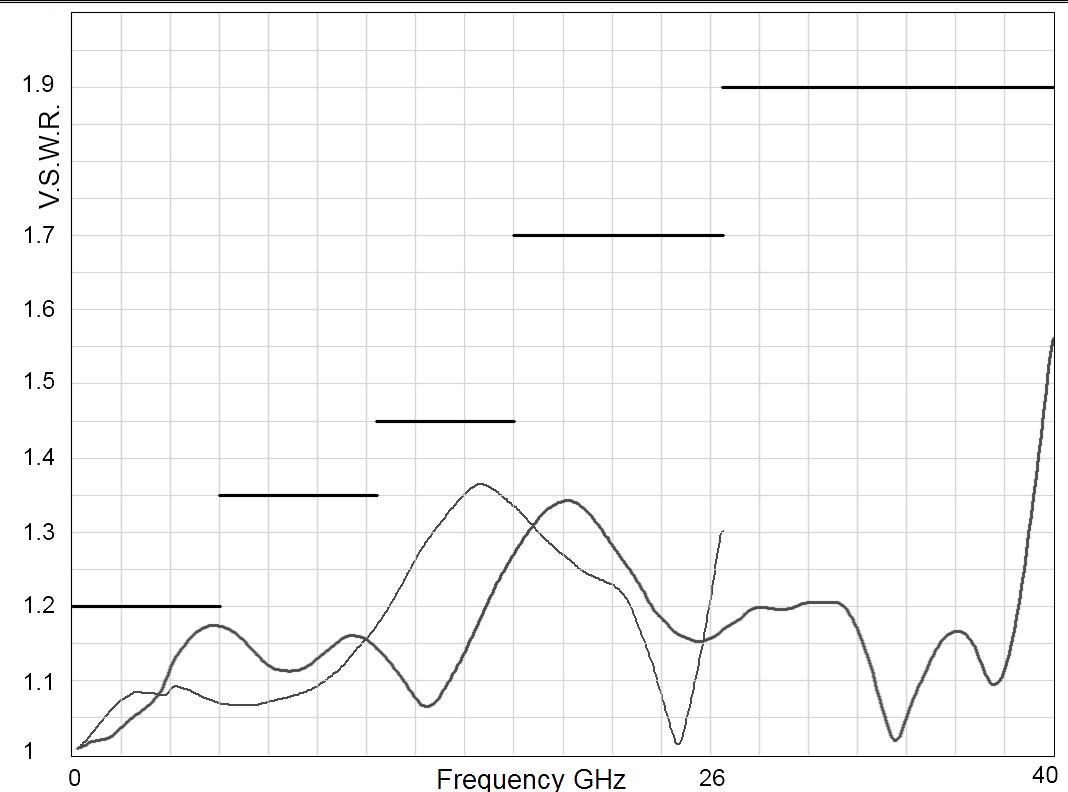
5-46 | SPNT SIMPLIFICATION IS OUR INNOVATION Visit www.radiall.com for more information
NUMBER R51-3-34-7 R51-3-36-7 R51-4-34-7 R51-4-36-7 R51-F-34-7 R51-F-36-7 R51-8-34-7 R51-8-36-7 Frequency Range GHz DC to 6 DC to 20 DC to 26 � 5 DC to 40 Impedance Ω 50 Insertion Loss (max) dB 0.3 + 0.015 × frequency (GHz) Isolation (min) dB 80 DC to 6 GHz 80 DC to 6 GHz 80 DC to 6 GHz 80 6 to 12 4 GHz 70 6 to 12 4 GHz 70 6 to 12 4 GHz 70 12 � 4 to 20 GHz 65 12 � 4 to 20 GHz 65 12 � 4 to 18 GHz 65 - 20 to 26 5 GHz 60 18 to 26 5 GHz 60 - - 26 5 to 40 GHz 55 V S W R (max) 1 20 DC to 6 GHz 1 20 DC to 6 GHz 1 20 DC to 6 GHz 1 20 6 to 12 4 GHz 1 35 6 to 12 4 GHz 1 35 6 to 12 4 GHz 1 35 12 4 to 20 GHz 1 45 12 4 to 20 GHz 1 45 12 4 to 18 GHz 1 45 - 20 to 26 � 5 GHz 1�70 18 to 26 � 5 GHz 1�70 - - 26 5 to 40 GHz 1 90
PART
- 120 dBC typical (2 carriers 20w) Repeatability (measured at 25 °C) 0 03 dB 0 05 dB SMA SMA 2.9 Frequency (GHz) Frequency (GHz) Titanium Series
Third order inter Modulation
RF
PERFORMANCE V.S.W.R
ELECTRONIC POSITION INDICATORS
The electronic position indicators use photo-MOS transistors, which are driven by the mechanical position of the RF paths moving elements. The circuitry consists of a common which can be connected to an output corresponding to a selected RF path. If one or several RF paths are closed, the corresponding indicators are connected to the common. The photo-MOS transistors are configured for AC and/or DC operation. The electronic position indicators require the supply (20 to 32 VDC) to be connected to pin 1 and ground connected to pin 15.
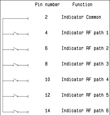
Notes Ways 1 and 4 are not connected for SP4T switches.
SPNT | 5-47 SIMPLIFICATION IS OUR INNOVATION Visit www.radiall.com for more information
Titanium Series
TYPE 7: WITH TTL (OPTION “2”) / WITHOUT TTL (OPTION “1”) & INDICATORS
Each RF path can be closed by applying ground or TTL "High" for option 2 to the corresponding "drive" pin. In general, except for Make-Before-Break drive, all other RF paths are simultaneously opened by internal logic.
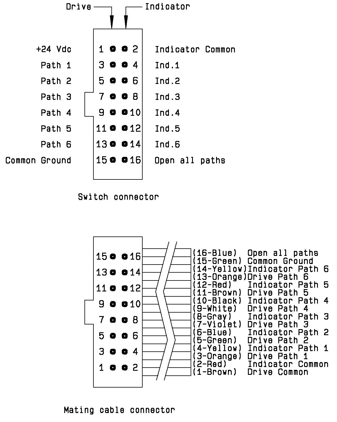
Standard drive option “1”:
• Connect pin 15 to ground
• Connect pin 1 to supply (+20 VDC to +32 VDC)
• Select (close) desired RF path by applying ground to the corresponding "drive" pin (Ex: apply ground to pin 3 to close RF path 1)
• To select another path, ensure that all unwanted RF path "drive" pins are disconnected from ground (to prevent multiple RF path engagement), then apply ground to the "drive" pin which corresponds to the desired RF path
• To open all RF paths, ensure that all RF path "drive" pins are disconnected from ground. Complete the operation by applying ground to pin 16
TTL drive option “2”:
• Connect pin 15 to ground
• Connect pin 1 to supply (+20 VDC to +32 VDC)
• Select (close) desired RF path by applying TTL "High" to the corresponding "drive" pin (Ex: apply TTL "High" to pin 3 to close RF path 1)
• To select another path, ensure that all unwanted RF path "drive" pins are in TTL "low" position (to prevent multiple RF path engagement), then apply TTL "high" to the "drive" pin which corresponds to the desired RF path
• To open all RF paths, ensure that all RF path "drive" pins are in TTL "Low" position. Complete the operation by applying TTL "High" to pin 16
Break-Before-Make:
Open the undesired RF path for at least 15 minutes (minimum), then close the new RF port
Make-Before-Break:
Ensure that the previously selected RF path “drive” is connected to ground (or TTL “High” for option “2”), then close the new RF path
Notes Ways 1 and 4 are not connected for SP4T switches.
5-48 | SPNT SIMPLIFICATION IS OUR INNOVATION Visit www.radiall.com for more information
Titanium Series
TYPICAL OUTLINE DRAWING
SMA CONNECTORS
Notes
All dimensions are in millimeters [inches]. Ways 1 and 4 are not connected for SP4T switches.
SPNT | 5-49 SIMPLIFICATION IS OUR INNOVATION Visit www.radiall.com for more information
SMA 2.9 CONNECTORS
Titanium Series
POWER RATING CHART
This graph is based on the following conditions:
• Ambient temperature: + 25 °C
• Sea level
• V.S.W.R.: 1 and cold switching
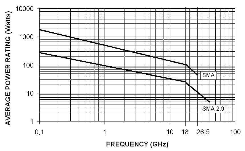
DERATING FACTOR VERSUS VSWR
The average power input must be reduced for load V.S.W.R. above 1:1.
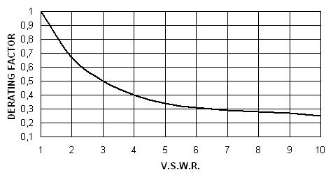
Notes Ways 1 and 4 are not connected for SP4T switches.
5-50 | SPNT SIMPLIFICATION IS OUR INNOVATION Visit www.radiall.com for more information
Average
Rating (Watts) Frequency (GHz)
Power
Titanium Series
HIGH PERFORMANCE MULTIPORT SWITCHES
SPNT TERMINATED UP TO 40 GHz
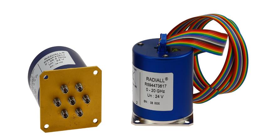
Radiall’s PLATINUM series switches are optimized to perform at a high level over an extended life cycle. With outstanding RF performance, and a guaranteed insertion loss repeatability of 0.03 dB over a life span of 10 million switching cycles, Radiall's PLATINUM series switches are a perfect solution for automated test and measurement equipment, as well as signal monitoring devices.
Example of P/N: R594873427 is a SPnT SMA 2.9 up to 40 GHz, Latching with Indicators, Self cut-off, Auto-Reset, TTL driver and HE10 connector.
PART NUMBER SELECTION
SERIES PREFIX
RF CONNECTORS
3: SMA up to 6 GHz
4: SMA up to 20 GHz
F: SMA up to 26 � 5 GHz
8: SMA 2�9 up to 40 GHz [1]
TYPE
4: Latching + Self cut-off without indicator
7: Latching + Self cut-off + Auto Reset + Indicators
ACTUATOR VOLTAGE
3: 24 Vdc
NUMBER OF POSITIONS
4: 4 positions
6: 6 positions
OPTIONS
1: Positive common (without TTL)
2: TTL/5 V logic with 24 Vdc supply [2 & 3]
ACTUATOR TERMINAL
7: HE 10 receptacle, delivered with 750 mm (30 inches) ribbon cable + HE10 connector
DOCUMENTATION
-: Certificate of conformity
C: Calibration certificate
R: Calibration certificate + RF curves
Notes
Ways 1 and 4 are not connected for SP4T switches.
1. Connector SMA 2.9 is equivalent to "K connector ®", registered trademark of Anritsu
2. Polarity is not relevant to application for switches with TTL driver
3. Only available with type "7"
SPNT | 5-51 SIMPLIFICATION IS OUR INNOVATION Visit www.radiall.com for more information
Platinum Series
R594
GENERAL SPECIFICATIONS
OPERATING MODE LATCHING
Nominal operating voltage (across operating temperature) Vdc 24 (20/32) Coil resistance (+/-10%) Ω 120
Operating current at 23 °C mA 200
Maximum stand-by current mA 50
Average power
TTL input
Indicator specifications
RF path Cold switching: See Power page 5-59 Hot switching: 1 Watt Cw
Internal terminations 1 Watt average into 50 Ω
Maximum withstanding voltage 60 V
Maximum current capacity 150 mA
Maximum "ON" resistance 2.5 Ω
Minimum "OFF" resistance 100 MΩ
Switching time (max) ms 15
Life (min) SMA 10 million cycles SMA 2 9 2 5 million cycles
Connectors SMA - SMA 2 �9
Actuator terminals HE10 ribbon receptacle
Weight (max) g 230
ENVIRONMENTAL SPECIFICATIONS
Operating temperature range -25 ºC to +75 ºC
Storage temperature range -55 ºC to +85 ºC
Temperature cycling (MIL-STD-202, Method 107D, Cond.A) -55 ºC to +85 ºC (10 cycles)
Vibration (MIL STD 202, Method 204D, Cond D) 10 - 2,000 Hz, 10 g - operating
Shock (MIL STD 202, Method 213B, Cond C) 50 g/6 ms, 1/2 sine - operating
Moisture resistance (MIL STD 202, Method 106E, Cond E) 65 ºC, 95% RH, 10 days
Altitude storage (MIL STD 202, Method 105C, Cond.B) 50,000 ft (15,240 meters)
RFI (MIL STD 1344, Method 3008 or IEC 61726) 55 dB at 20 GHz Magnetic field < 5.10-5 gauss at 1 meter
5-52 | SPNT SIMPLIFICATION IS OUR INNOVATION Visit www.radiall.com for more information
Platinum Series
High
max
Max
level 3 to 7 V 1 4 mA
at Vcc =
Low level 0 to 0 8 Volts -
RF PERFORMANCE
TYPICAL RF PERFORMANCE
V.S.W.R INSERTION LOSS & ISOLATION
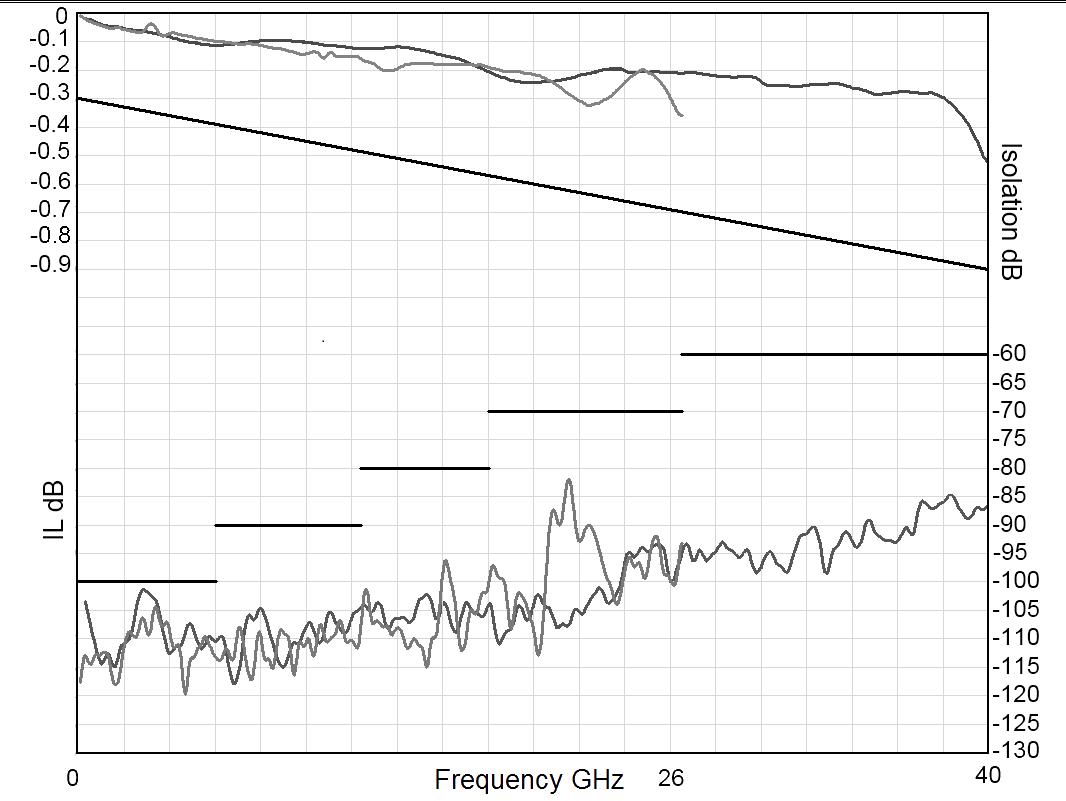
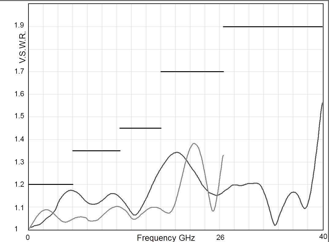
SPNT | 5-53 SIMPLIFICATION IS OUR INNOVATION Visit www.radiall.com for more information Frequency (GHz) SMA SMA 2.9
Series
Platinum
PART NUMBER R5943-34-7 R5944-34-7 R5944-36-7 R594F-34-7 R594F-36-7 R5948-34-7 R5948-36-7 Frequency Range GHz DC to 6 DC to 20 DC to 26 � 5 DC to 40 Impedance Ω 50 Insertion Loss (max) dB 0.3 + 0.015 × frequency (GHz) Isolation (min) dB 100 DC to 6 GHz 100 DC to 6 GHz 100 DC to 6 GHz 100 6 to 12 4 GHz 90 6 to 12 4 GHz 90 6 to 12 4 GHz 90 12 � 4 to 20 GHz 80 12 � 4 to 20 GHz 80 12 � 4 to 18 GHz 80 - 20 to 26 5 GHz 70 18 to 26 5 GHz 70 - - 26 5 to 40 GHz 60 V S W R (max) 1 20 DC to 6 GHz 1 20 DC to 6 GHz 1 20 DC to 6 GHz 1 20 6 to 12 4 GHz 1 35 6 to 12 4 GHz 1 35 6 to 12 4 GHz 1 35 12 4 to 20 GHz 1 45 12 4 to 20 GHz 1 45 12 4 to 18 GHz 1 45 - 20 to 26 � 5 GHz 1�70 18 to 26 � 5 GHz 1�70 - - 26 5 to 40 GHz 1 90 Repeatability (measured at 25 °C) 0 03 dB 0 05 dB
Frequency (GHz)
ELECTRONIC POSITION INDICATORS
(This option is not available with type 4)
The electronic position indicators use photo-MOS transistors, which are driven by the mechanical position of the RF paths moving elements. The circuitry consists of a common which can be connected to an output corresponding to selected RF path. If one or several RF paths are closed, the corresponding indicators are connected to the common. The photo-MOS transistors are configured for AC and/or DC operation. The electronic position indicators require the supply (20 to 32 VDC) to be connected to pin 1 and ground connected to pin 15.
Notes Ways 1 and 4 are not connected for SP4T switches.
5-54 | SPNT SIMPLIFICATION IS OUR INNOVATION Visit www.radiall.com for more information
Series
Platinum
DRIVING THE SWITCH
Each RF path is driven independently, and can be closed or open by applying ground to the corresponding "open” or “close" pin�
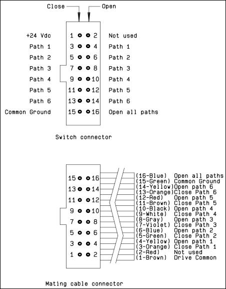
Standard drive:
• Connect pin 15 to ground
• Connect pin 1 to supply (+20 VDC to +32 VDC)
• Select desired RF path by applying ground to the corresponding "close" pin (Ex: ground pin 3 to close RF path 1)
• To open desired RF path connect ground to the corresponding "open" pin (Ex: ground pin 4 to open RF path 1)
• To open all RF paths, first ensure that all RF path "close" pins are disconnected from ground, then to complete the operation, connect pin 16 to ground
Make-Before-Break:
Make-Before-Break switching can be accomplished by closing the new RF path before opening the previously selected RF path. To complete the operation, close the new RF port for at least 15 minutes (minimum), then open the previously selected RF port
SPNT | 5-55 SIMPLIFICATION IS OUR INNOVATION Visit www.radiall.com for more information
SP4T switches. Platinum
INDICATOR
Notes Ways 1 and 4 are not connected for
Series TYPE 4: WITHOUT TTL AND WITHOUT
TYPE 7: WITH TTL (OPTION “2”) / WITHOUT TTL (OPTION “1”) & INDICATORS
Each RF path can be closed by applying Ground or TTL "High" for option 2 to the corresponding "drive" pin. In general, except for Make-Before-Break drive, all other RF paths are simultaneously opened by internal logic.
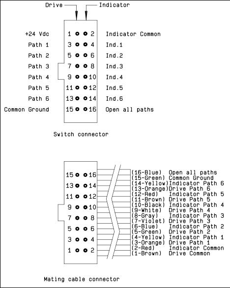
Standard drive option “1”:
• Connect pin 15 to ground
• Connect pin 1 to supply (+20 VDC to +32 VDC)
• Select (close) desired RF path by applying ground to the corresponding "drive" pin (Ex: apply ground to pin 3 to close RF path 1)
• To select another path, ensure that all unwanted RF path "drive" pins are disconnected from ground (to prevent multiple RF path engagement), then apply ground to the "drive" pin which corresponds to the desired RF path
• To open all RF paths, ensure that all RF path "drive" pins are disconnected from ground, then complete the operation by applying ground to pin 16
TTL drive option “2”:
• Connect pin 15 to ground
• Connect pin 1 to supply (+20 VDC to +32 VDC)
• Select (close) desired RF path by applying TTL "High" to the corresponding "drive" pin (Ex: apply TTL "High" to pin 3 to close RF path 1)
• To select another path, ensure that all unwanted RF path "drive" pins are in TTL "Low" position (to prevent multiple RF path engagement), then apply TTL "High" to the "drive" pin which corresponds to the desired RF path
• To open all RF paths, ensure that all RF path "drive" pins are in TTL "Low" position, then complete the operation by applying TTL "High" to pin 16
Break-Before-Make:
Open the undesired RF path after 15 minutes (minimum), then close the new RF port.
Make-Before-Break:
Ensure that the previously selected RF path “drive” is connected to ground (or TTL “High” for option “2”), then close the new RF path.
Notes Ways 1 and 4 are not connected for SP4T switches.
5-56 | SPNT SIMPLIFICATION IS OUR INNOVATION Visit www.radiall.com for more information
Platinum Series
TYPICAL OUTLINE DRAWING
SMA CONNECTORS
Notes
All dimensions are in millimeters [inches]. Ways 1 and 4 are not connected for SP4T switches. Platinum Series
SMA 2.9 CONNECTORS
SPNT | 5-57 SIMPLIFICATION IS OUR INNOVATION Visit www.radiall.com for more information
POWER RATING CHART
This graph is based on the following conditions:
• Ambient temperature: + 25 °C
• Sea level
• V.S.W.R.: 1 and cold switching
DERATING FACTOR VERSUS VSWR
The average power input must be reduced for load V.S.W.R. above 1:1.
5-58 | SPNT SIMPLIFICATION IS OUR INNOVATION Visit www.radiall.com for more information
Average
Power Rating (Watts)
Frequency (GHz)
Platinum Series
Optional Features
OPTIONAL FEATURES EXAMPLES OF DEDICATED APPLICATION OPTIONS
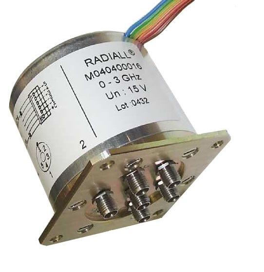
SPnT with flat ribbon cable for easy installation with limited space
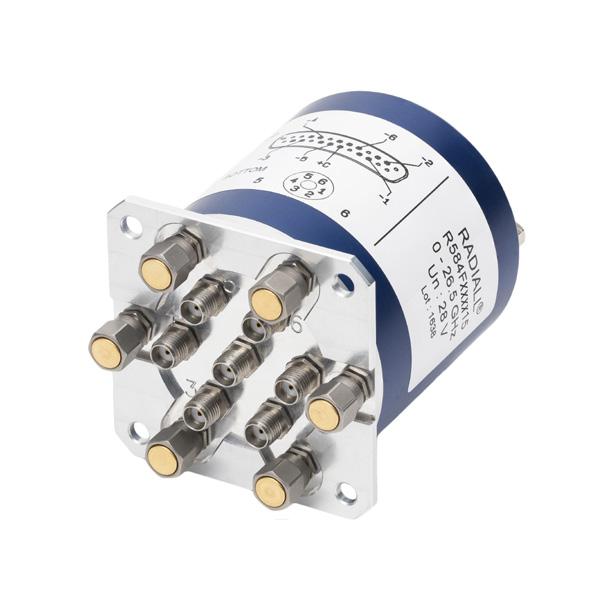
SPnT models can be fitted with external loads (up to 50 GHz) for an easy maintenance of equipment.
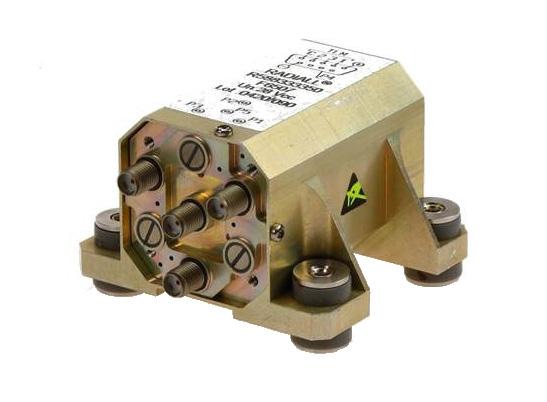
SP3T used for a military application with sequential access and severe environmental characteristics
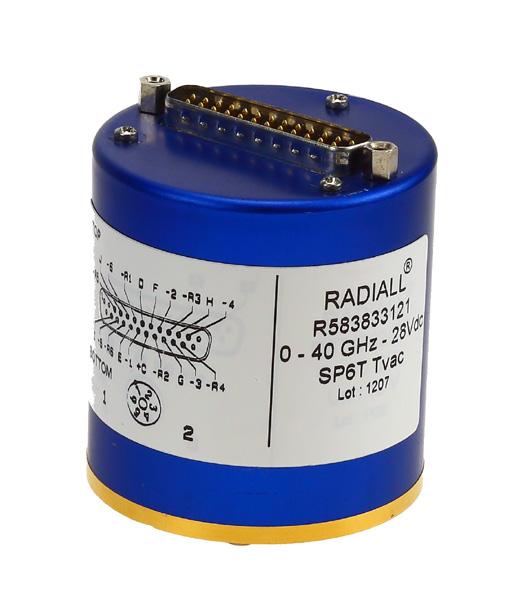
Thermal vacuum SPnT up to 50 GHz designed based on our expertise in Space For more detailed information, see page 7-18 to 7-20.
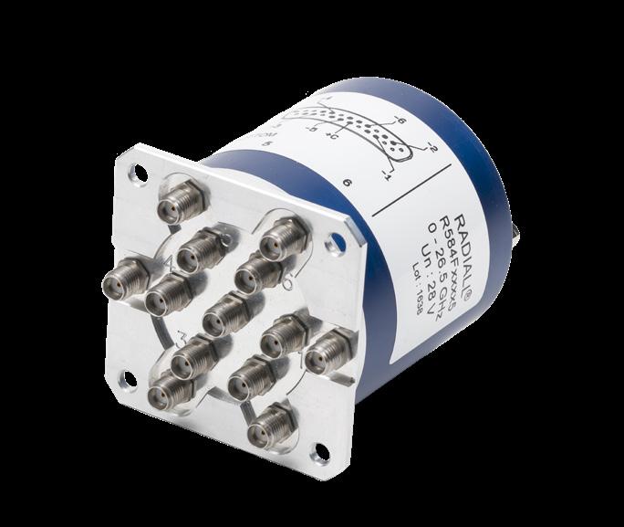
7P6T switch for a Custom Matrix Switch ( 4P3T ) with 4 Input ports and 4 Output ports configured for 3 transmission systems and one redundancy channel (N+1: N type) for example
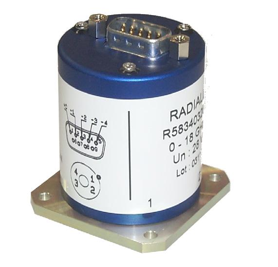
Unterminated SP3-6T with 9 pins D-sub connector instead of solder pins
SPNT | 5-59 SIMPLIFICATION IS OUR INNOVATION Visit www.radiall.com for more information
5-60 | SPNT SIMPLIFICATION IS OUR INNOVATION Visit www.radiall.com for more information
Notes
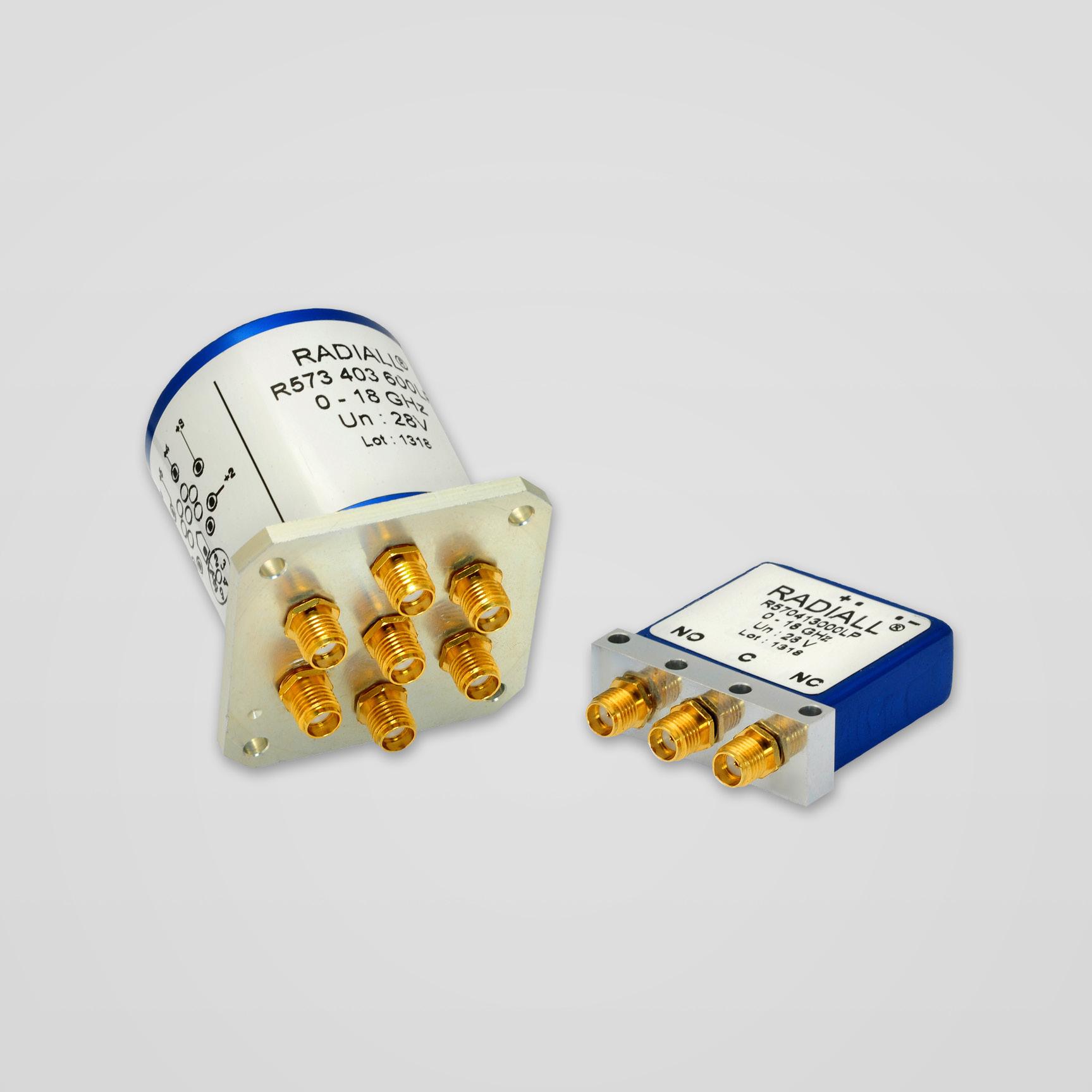
SIMPLIFICATION IS OUR INNOVATION Visit www.radiall.com for more information SECTION 6
LOW PIM
Section 6 Table of Contents
SERIES SPDT up to 18 GHz: R570xxxxxxLP Series
LOW PIM PART NUMBER SELECTION GUIDE [1]
RAMSES SPnT R573LP 1 4 - 2/3/4/5/8/9 0/1 2 3 4/6
Notes
Example of P/N: R573423600LP is a SP6T SMA 18 GHz, latching, 28 Vdc, without option, solder pins. 1. For part number creation and available options, see detailed part number selection for each series.
LOW PIM | 6-1 SIMPLIFICATION IS OUR INNOVATION Visit www.radiall.com for more information
Series ��������������������������������������������������������������������������������������������������������������� 6-7 to 6-11
GHz:
Series 6-12
6-15 Coaxial
�������������������������������������������������������������������������������������������������������������� 6-16
RAMSES
6-2 to 6-6 DPDT up to 18 GHz: R577xxxxxxLP
SPnT up to 18
R573xxxxxxLP
to
Low PIM Switches - Electrical Schematics
DIGITAL POSITION R 1-3: 4: RF CONNECTORS 5: TYPE 6: VOLTAGE 7: TTL 8: OPTIONS 9: TERMINALS Series ConfigurationN 12 � 4 GHz SMA 18 GHz Failsafe Latching Normally open [1] 12 V 28 V Without TTL With TTL Without option Positive common Supression diodes Positive common and suppression diodes Solder pins D-Sub connector RAMSES SPDT R570LP 1 4 0/1 2/3/5/6 - 2 3 0 1 0 1 3 4 0 5 DPDT R577LP 1 4 0/1 2/3/5/6 - 2 3 0 1 0 1 3 4 0 5
DIGITAL POSITION R 1-3: 4: RF CONNECTORS 5: TYPE 6: VOLTAGE 7: POS. 8: OPTIONS 9: TERMINALS Series Configuration N 12 4 GHz SMA 18 GHz Failsafe Latching Normally open [1] 12 V 28 V Number of positions With TTL Without option Positive common TTL Driver Supression diodes Positive common and suppression diodes Solder pins D-Sub connector
0 1 2 3 4 0 5
RAMSES Series
SPDT LOW PIM UP TO 18 GHz
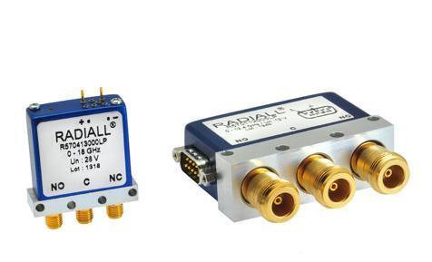
To meet growing market demands created by the deployment of 4G/LTE networks, Radiall has introduced a new range of Low PIM switches. RAMSES SPDT Low PIM switches are perfectly suited for RF test systems and test benches requiring excellent passive intermodulation performance up to 18 GHz; with a guarantee PIM performance of -160 dBc at +43 dBm over a life span of 2 million switching cycles. These products are specific to instrumentation and telecommunication applications �
Example of P/N: R570413030LP is a SPDT Low PIM SMA 18 GHz, failsafe, 28 Vdc, with supression diodes, solder pins.
PART NUMBER SELECTION
SERIES PREFIX
FREQUENCY RANGE
1: N up to 12 4 GHz
4: SMA up to 18 GHz
TYPE
1: Failsafe
2: Failsafe + I C
3: Latching
4: Latching + I.C.
5: Latching + S.C.O. [1]
6: Latching + S.C.O. + I.C. [1]
ACTUATOR VOLTAGE
2: 12 Vdc
3: 28 Vdc
TTL OPTION
0: Without TTL driver
1: With TTL driver [1 & 3]
OPTIONS [5]
0: Without option
1: Positive common [2]
3: With suppression diodes
4: With suppression diodes and positive common [2]
ACTUATOR TERMINALS
0: Solder pins
5: D-Sub connector [4]
Notes
I.C.: Indicator contact - S.C.O.: Self Cut-Off
1. Suppression diodes are already included in Self Cut-OFF & TTL option
2. Positive common shall be specified only with type 3, 4, 5 & 6 because failsafe models can be used with both polarities
3. Polarity is not relevant to application for switches with TTL driver
4. Only available for N models
6-2 | LOW PIM SIMPLIFICATION IS OUR INNOVATION Visit www.radiall.com for more information
R570 LP
RAMSES Series
GENERAL SPECIFICATIONS
Average power
See Power Rating Chart on page 1-16
Indicator rating 1 Watt/30 Volts/100 mA
Switching time ms 15 ms
Life (Min) 2 million cycles
Connectors
Actuator terminals
SMA - N
Solder pins or male 25 pin D-Sub connector
Operating temperature range -40°C to +85°C
Storage temperature range -55°C to +85°C
Vibration (MIL STD 202, method 204D, cond D) 10 - 2,000 Hz - 20 g
Shock (MIL STD 202, method 213B, cond C)
Reset: supply voltage time 1 sec. max./duty cycle 10%
RF PERFORMANCE
PASSIVE INTERMODULATION
TONE 1 1,810 MHz, approximately 43 dBm
TONE 2 1,850 MHz, approximately 43 dBm
3RD ORDER PIM 160 dBc at 1,770 MHz
Depending on application, carrier powers and frequencies — PIM measurements can vary. PIM testing is not measured during product acceptance test.
OUTSTANDING PIM PERFORMANCE
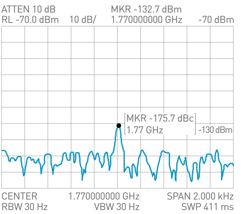
LOW PIM | 6-3 SIMPLIFICATION IS OUR INNOVATION Visit www.radiall.com for more information
OPERATING MODE FAILSAFE LATCHING Nominal operating
temperature) Vdc 12 (10 � 2 to 13) 28 (24 to 30) 12 (10 � 2 to 13) 28 (24 to 30) Coil resistance at 23 °C (+/10%) SMA Ω 47 5 275 58 350 N 38 200 38 225 Operating current at 23 °C SMA mA 250 102 210 80 N 320 140 320 125
voltage (across operating
TTL input High level 2 2 to 5 5 V (TTL Option )/3 5 to 5 5 V ( BCD Option) Low level 0 to 0 8 V (TTL Option )/0 to
5
BCD Option)
1
V (
operating
100 g/6 ms
½
operating
-
sine
CONNECTORS FREQUENCY RANGE GH z V.S.W.R. (MAX) INSERTION LOSS (MAX) dB ISOLATION (MIN) dB IMPEDANCE Ω THIRD ORDER INTERMODULATION N DC - 12 4 DC - 1 1 15 0 15 85 50 -160 dBc at +43 dBm (2 carriers 20 W) 1 - 2 1� 20 0� 20 80 2 - 3 1 25 0 25 75 3 - 8 1 35 0 35 70 8 - 12 4 1 50 0 50 60 SMA DC - 18 DC - 3 1 10 0 15 80 3 - 8 1 20 0 20 75 8 - 12 � 4 1 20 0� 25 65 12 4 - 18 1 40 0 35 60
RAMSES Series
TYPICAL RF PERFORMANCE
Example: SPDT N up to 12.4 GHz
INSERTION LOSS & ISOLATION
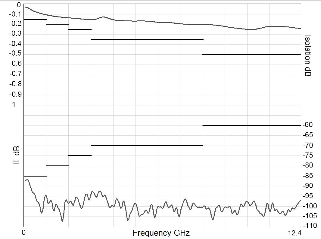
Frequency (GHz)
Example: SPDT SMA up to 18 GHz
INSERTION LOSS & ISOLATION
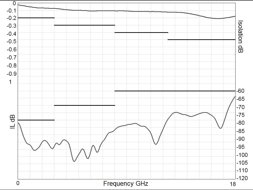
Frequency (GHz)
Notes
See electrical schematics from page 2-20 to 2-23.
V.S.W.R
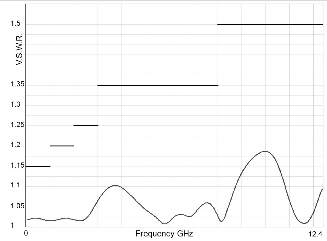
Frequency (GHz)
V.S.W.R
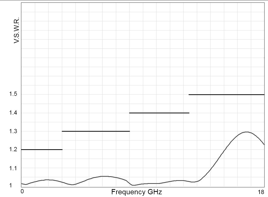
Frequency (GHz)
6-4 | LOW PIM SIMPLIFICATION IS OUR INNOVATION Visit www.radiall.com for more information
RAMSES Series
TYPICAL OUTLINE DRAWING
EXAMPLE: SPDT N UP TO 12.4 GHz WITH PINS
EXAMPLE: SPDT SMA UP TO 18 GHz
Notes
All dimensions are in millimeters [inches].
EXAMPLE: SPDT N UP TO 12.4 GHz WITH D-SUB
LOW PIM | 6-5 SIMPLIFICATION IS OUR INNOVATION Visit www.radiall.com for more information
RAMSES Series
DPDT LOW PIM UP TO 18 GHz
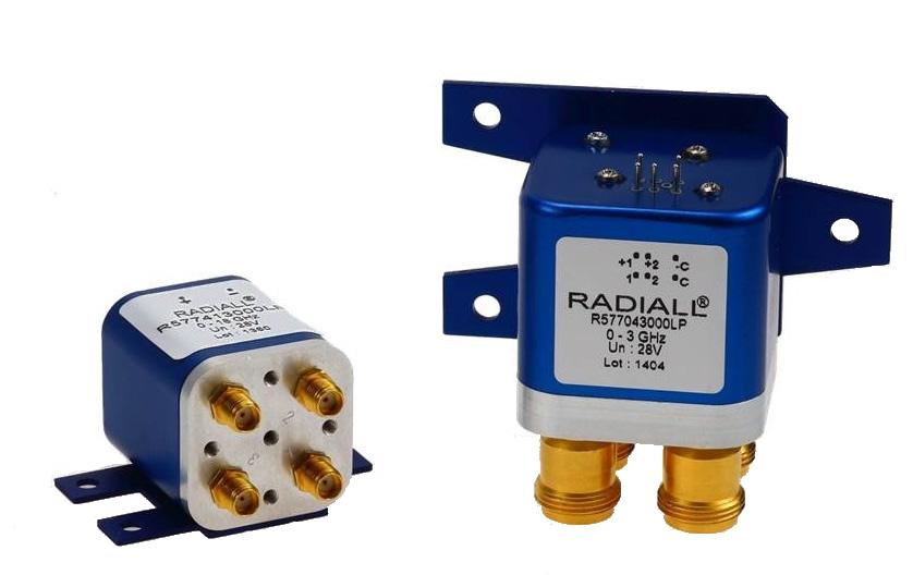
PART NUMBER SELECTION
SERIES PREFIX
FREQUENCY RANGE
1: N up to 12 � 4 GHz
4: SMA up to 18 GHz
TYPE
1: Failsafe
2: Failsafe + I C
3: Latching
4: Latching + I.C.
5: Latching + S.C.O. [1]
6: Latching + S.C.O. + I.C. [1]
ACTUATOR VOLTAGE
2: 12 Vdc
3: 28 Vdc
TTL OPTION
0: Without TTL driver
1: With TTL driver [1 & 3]
OPTIONS
0: Without option
1: Positive common [2]
3: With suppression diodes
To meet growing market demands created by the deployment of 4G/LTE networks, Radiall has introduced a new range of Low PIM switches. RAMSES DPDT Low PIM switches are perfectly suited for RF test systems and test benches requiring excellent passive intermodulation performance up to 18 GHz; with a guarantee PIM performance of -160 dBc at +43 dBm over a life span of 2 million switching cycles. These products are specific to instrumentation and telecommunication applications
Example of P/N: R577163105LP is a DPDT Low PIM N 12.4 GHz latching with Indicators, Self Cut-Off, 28 Vdc, TTL driver, D-Sub connector.
4: With suppression diodes and positive common [2]
ACTUATOR TERMINALS
0: Solder pins
5: D-Sub connector [4]
Notes
I.C.: Indicator contact - S.C.O.: Self Cut-Off
1. Suppression diodes are already included in Self Cut-Off & TTL option
2. Positive common shall be specified only with type 3, 4, 5 & 6 because failsafe models can be used with both polarities
3. Polarity is not relevant to application for switches with TTL driver
6-6 | LOW PIM SIMPLIFICATION IS OUR INNOVATION Visit www.radiall.com for more information
R577 LP
RAMSES Series
GENERAL SPECIFICATIONS
Average power See Power Rating Chart on page 1-13
rating
Switching time (max) ms 15 Life (min) 2 million cycles
Connectors SMA - N
Actuator terminals
Solder pins or male 9 pin D-Sub connector
Operating temperature range -40°C to +85°C
Storage temperature range -55°C to +85°C
Vibration (MIL STD 202, method 204D, cond C)
(MIL STD 202, method 213B, cond G)
RF PERFORMANCE
CONNECTORS
PASSIVE INTERMODULATION
TONE 1 1,810 MHz, approximately 43 dBm
TONE 2 1,850 MHz, approximately 43 dBm
3RD ORDER PIM 160 dBc at 1,770 MHz
Depending on application, carrier powers and frequencies — PIM measurements can vary. PIM testing is not measured during product acceptance test.
OUTSTANDING PIM PERFORMANCE
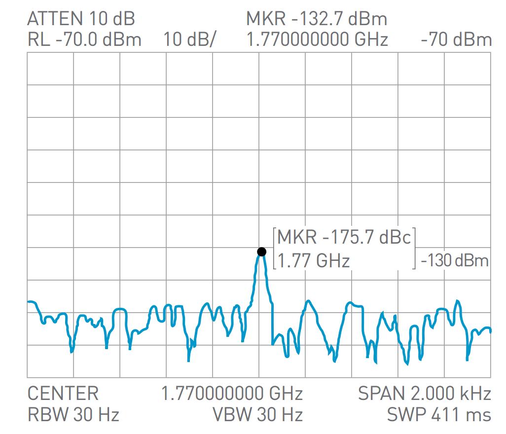
LOW PIM | 6-7 SIMPLIFICATION IS OUR INNOVATION Visit www.radiall.com for more information
OPERATING
NORMALLY OPEN LATCHING Nominal operating
Vdc 12 (10 � 2 to 13) 28 (24 to 30) 12 (10 � 2 to 13) 28 (24 to 30) Coil resistance (+/-10%) Ω 35 200 38 225 Nominal operating current at 23 °C mA 340 140 320 125
MODE
voltage (across operating temperature)
TTL input High level 2 2 to 5 5 V 800 μA max 5.5 V Low level 0 to 0� 8 V 20 μA max 0.8 V
Indicator
1 W/30 V/100 mA
10-2000 Hz, 10 g operating
50 g/11 ms, ½ sine operating
Shock
FREQUENCY RANGE GH z V.S.W.R. (MAX) INSERTION LOSS (MAX) dB ISOLATION (MIN) dB IMPEDANCE Ω THIRD ORDER INTERMODULATION N DC - 3 DC - 12 4 DC - 1 1 15 0 15 85 50 -160 dBc at +43 dBm (2 carriers 20 W) 1 - 2 1� 20 0� 20 80 2 - 3 1 25 0 25 75
- 8 1 35 0 35 70 8 - 12 4 1 50 0 50 60 SMA DC - 3 DC - 18 DC - 3 1 20 0 20 80 3 - 8 1 30 0 30 70 8 - 12 4 1 40 0 40 65 12 4 - 18 1 50 0 50 60
3
RAMSES Series
TYPICAL RF PERFORMANCE
Example: DPDT N up to 12.4 GHz
INSERTION LOSS & ISOLATION
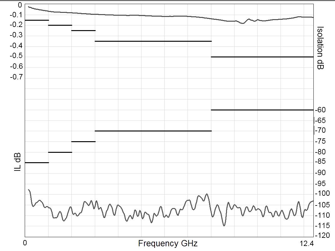
Frequency (GHz)
Example: DPDT SMA up to 18 GHz
INSERTION LOSS & ISOLATION
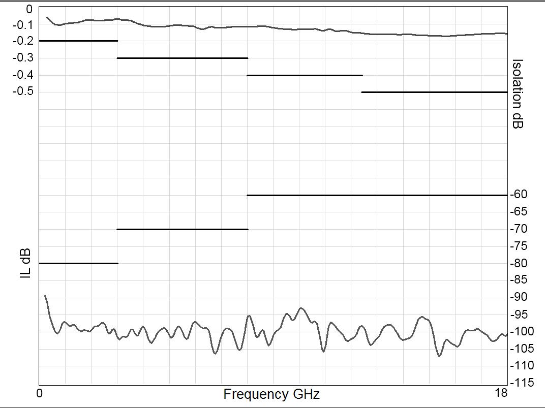
Frequency (GHz)
Notes
See electrical schematics from page 4-10 to 4-13.
V.S.W.R
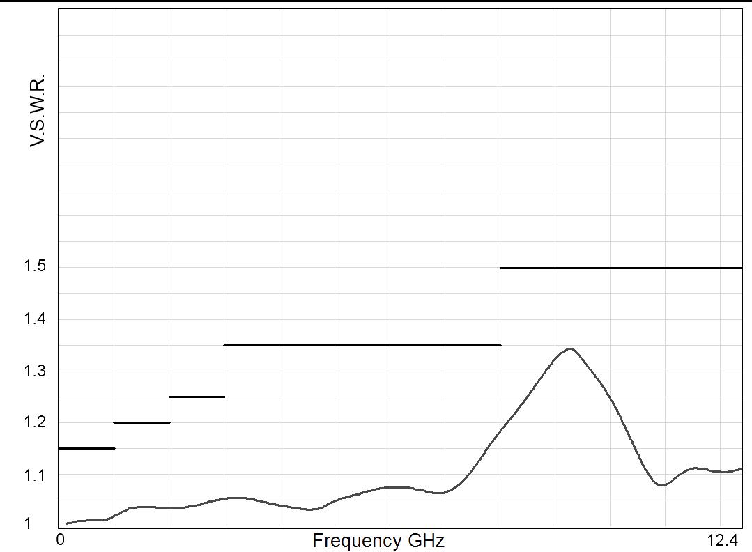
Frequency (GHz)
V.S.W.R
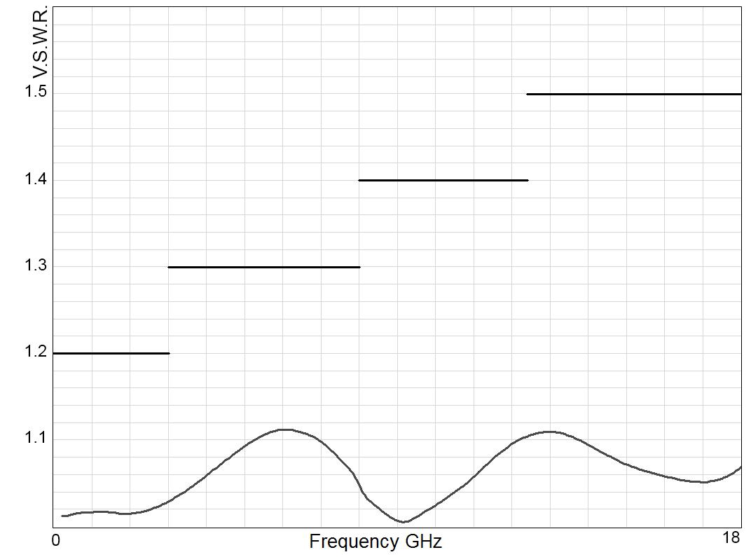
Frequency (GHz)
6-8 | LOW PIM SIMPLIFICATION IS OUR INNOVATION Visit www.radiall.com for more information
RAMSES Series
TYPICAL OUTLINE DRAWING
EXAMPLE: DPDT N UP TO 12.4 GHz WITH PINS
EXAMPLE: DPDT SMA UP TO 18GHz WITH PINS
Notes
All dimensions are in millimeters [inches].
EXAMPLE: DPDT N UP TO 12.4 GHz WITH D-SUB
EXAMPLE: DPDT SMA UP TO 18 GHz WITH D-SUB
LOW PIM | 6-9 SIMPLIFICATION IS OUR INNOVATION Visit www.radiall.com for more information
RAMSES Series
SPNT LOW PIM UP TO 18 GHz
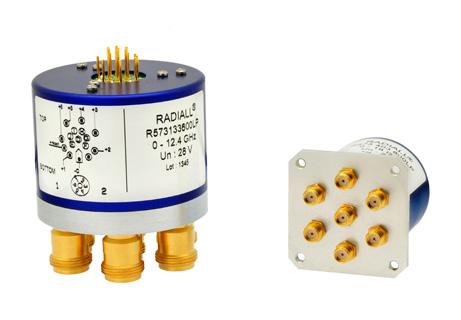
To meet growing market demands created by the deployment of 4G/LTE networks, Radiall has introduced a new range of Low PIM switches. RAMSES SPnT Low PIM switches are perfectly suited for RF test systems and test benches requiring excellent passive intermodulation performance up to 18 GHz; with a guarantee PIM performance of -160 dBc at +43 dBm over a life span of 2 million switching cycles. These products are specific to instrumentation and telecommunication applications
Example of P/N: R573403600LP is a SP6T Low PIM SMA up to 18 GHz, Normally Open, 28 Vdc, without option and solder pins.
PART NUMBER SELECTION
SERIES PREFIX
MODEL
3: Without 50 Ω termination
RF CONNECTORS
1: N up to 12 � 4 GHz
4: SMA up to 18 GHz
TYPE
0: Normally open
1: Normally open + I �C �
2: Latching
3: Latching +I.C.
4: Latching + S.C.O. [1]
5: Latching + S.C.O. + I.C. [1]
8: Latching + S.C.O. + A.R. [1]
9: Latching + S.C.O. + I.C. + A.R. [1]
ACTUATOR VOLTAGE
2: 12 Vdc
3: 28 Vdc
R57
LP
ACTUATOR TERMINALS
0: Solder pins
5: D-Sub connector
OPTIONS
0: Without option
1: Positive common [5]
2: Compatible TTL driver [1 & 2]
3: With suppression diodes
4: With suppression diodes and positive common [3]
8: BCD TTL driver compatible [1, 2, 4, & 5]
NUMBER OF POSITIONS
4: 4 Positions
6: 6 Positions
Notes
I.C.: Contact / S.C.O.: Self Cut-Off / A.R.: Auto Reset
1. These models are already equipped with suppression diodes
2. Polarity is not relevant to application for switches with TTL driver
3. Option available only for type 0, 1, 2 and 3
4. Latching BCD driver enables also a global reset through driver code 0000 (see BCD logic coding page 1-11)
5. Option available only with type 0, 1, 2, 3 and with type 8 and 9 combined with 28 Vdc.
6-10 | LOW PIM SIMPLIFICATION IS OUR INNOVATION Visit www.radiall.com for more information
3
RAMSES Series
GENERAL SPECIFICATIONS
Type 2, 3, 4 and 5:
Latching models have a RESET pin which commands the reset of all positions. This command should be used before switching from one position to another. If not, two positions will be set at the same time.
Note: During the RESET operation the global current is the nominal operating current multiplied by the number of positions.
Type 8, 9:
Latching models with AUTOMATIC RESET are available; these products have an internal SET/RESET circuit which automatically resets all the non-selected positions and sets the desired position. This option simplifies the use of latching switches by suppressing the RESET command in switching sequence. An electronic circuit supplies successively groups of 2, 3 or 4 actuators, in order to limit the maximum current. The current with this option is the total current of 2, 3 or 4 reset coils in the same time (see table below).
Example: During the AUTOMATIC RESET operation, at 28 Vdc, 4 position switch has a temporary consumption of only 250 mA, during 40 ms maximum.
SWITCHING SEQUENCE
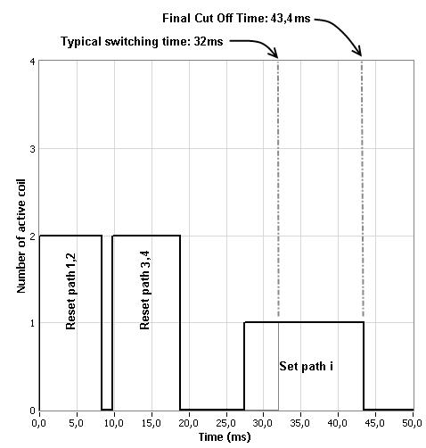
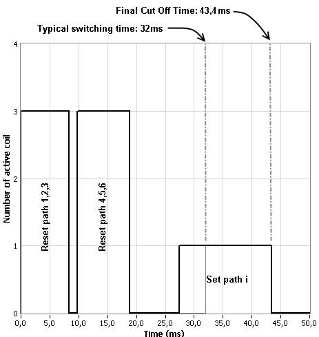
Notes
See electrical schematics from page 5-38 to 5-43.
LOW PIM | 6-11 SIMPLIFICATION IS OUR INNOVATION Visit www.radiall.com for more information
FOR SP6T
FOR SP4T
GENERAL SPECIFICATIONS
OPERATING MODE NORMALLY OPEN
Average power See Power Rating Chart on page 1-13
Switching time (max) ms 15 For automatic reset models: 40 Life (min) 2
Connectors SMA - N
Actuator terminals
Solder pins or male 25 pin D-Sub connector
Operating temperature range -25 °C to +70 °C
Storage temperature range -55 °C
(MIL STD 202, method 213B, cond C)
*Reset: supply voltage time 1 sec. max./duty cycle 10%
RF PERFORMANCE
CONNECTORS
PASSIVE INTERMODULATION
TONE 1 1,810 MHz, approximately 43 dBm
TONE 2 1,850 MHz, approximately 43 dBm
3RD ORDER PIM 160 dBc at 1,770 MHz
Depending on application, carrier powers and frequencies — PIM measurements can vary. PIM testing is not measured during product acceptance test.
OUTSTANDING PIM PERFORMANCE
6-12 | LOW PIM SIMPLIFICATION IS OUR INNOVATION Visit www.radiall.com for more information
LATCHING Nominal operating voltage (across operating temperature) Vdc 12 (10 2 to 13) 28 (24 to 30) 12 (10 2 to 13) 28 (24 to 30) Coil resistance at 23 °C (+/-10%) Ω 47� 5 275 38 225 Nominal operating current at 23 °C mA 250 102 320 Reset SP4T: 1280 mA* Reset SP6T: 1920 mA* 125 Reset SP4T: 500 mA* Reset SP6T: 750 mA*
High level 2 � 2 to 5 � 5 V (TTL Option) / 3 � 5 to 5 � 5 V (BCD Option) Low level 0 to 0 8 V (TTL Option) / 0 to 1 5 V (BCD Option)
TTL input
Indicator rating 1 W/30 V/100 mA
million cycles
°C
10 - 2,000 Hz , 20 g operating Shock
100 g/6 ms, ½ sine operating
to +85
Vibration (MIL STD 202, method 204D, cond � D)
NUMBER OF POSITIONS FREQUENCY RANGE GH z V.S.W.R. (MAX) INSERTION LOSS (MAX) dB ISOLATION (MIN) dB IMPEDANCE Ω THIRD ORDER INTERMODULATION SMA 4 and 6 DC - 18 DC - 3 1 20 0 20 80 50 -160 dBc at +43 dBm (2 carriers 20 W) 3 - 8 1 30 0 30 70 8 - 12 4 1 40 0 40 60 12 � 4 - 18 1� 50 0� 50 60 N DC - 12 � 4 DC - 3 1 20 0 20 80 3 - 8 1� 35 0� 35 70 8 - 12 4 1 50 0 50 60
RAMSES Series
RAMSES Series
TYPICAL RF PERFORMANCE
Example: SP6T N up to 12.4 GHz
INSERTION LOSS & ISOLATION
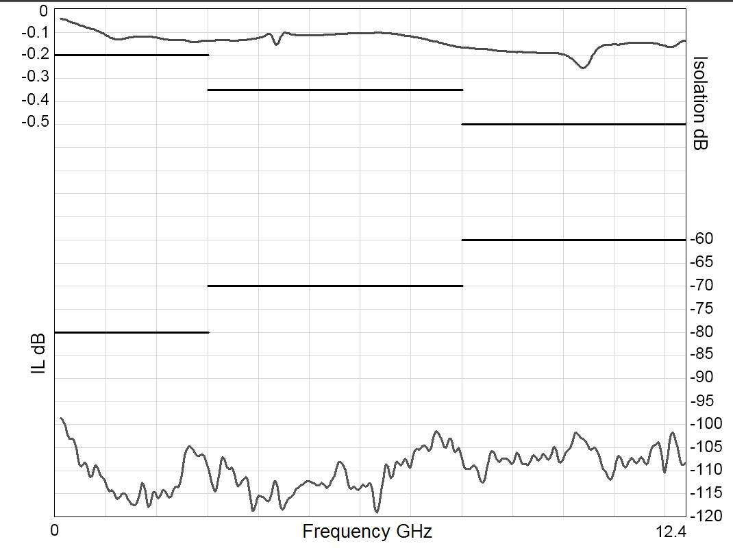
Frequency (GHz)
Example: SP6T SMA up to 18 GHz
INSERTION LOSS & ISOLATION
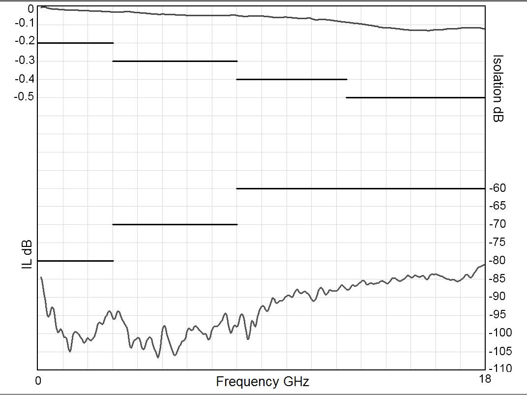
Frequency (GHz)
V.S.W.R
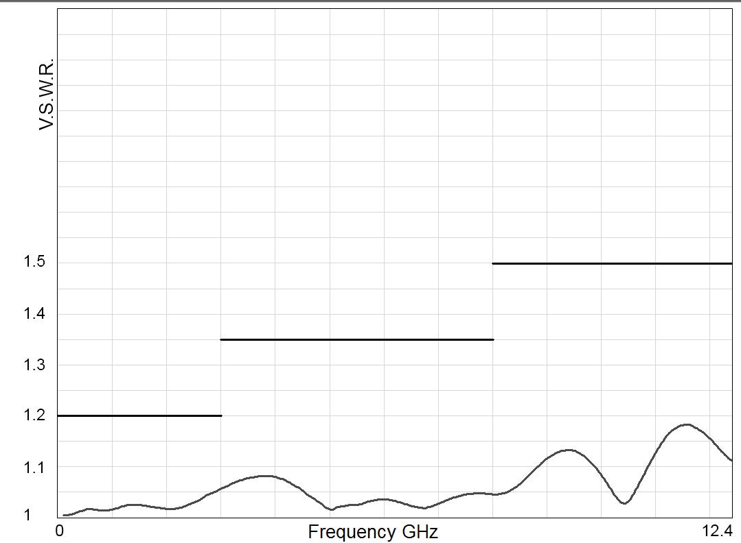
Frequency (GHz)
V.S.W.R
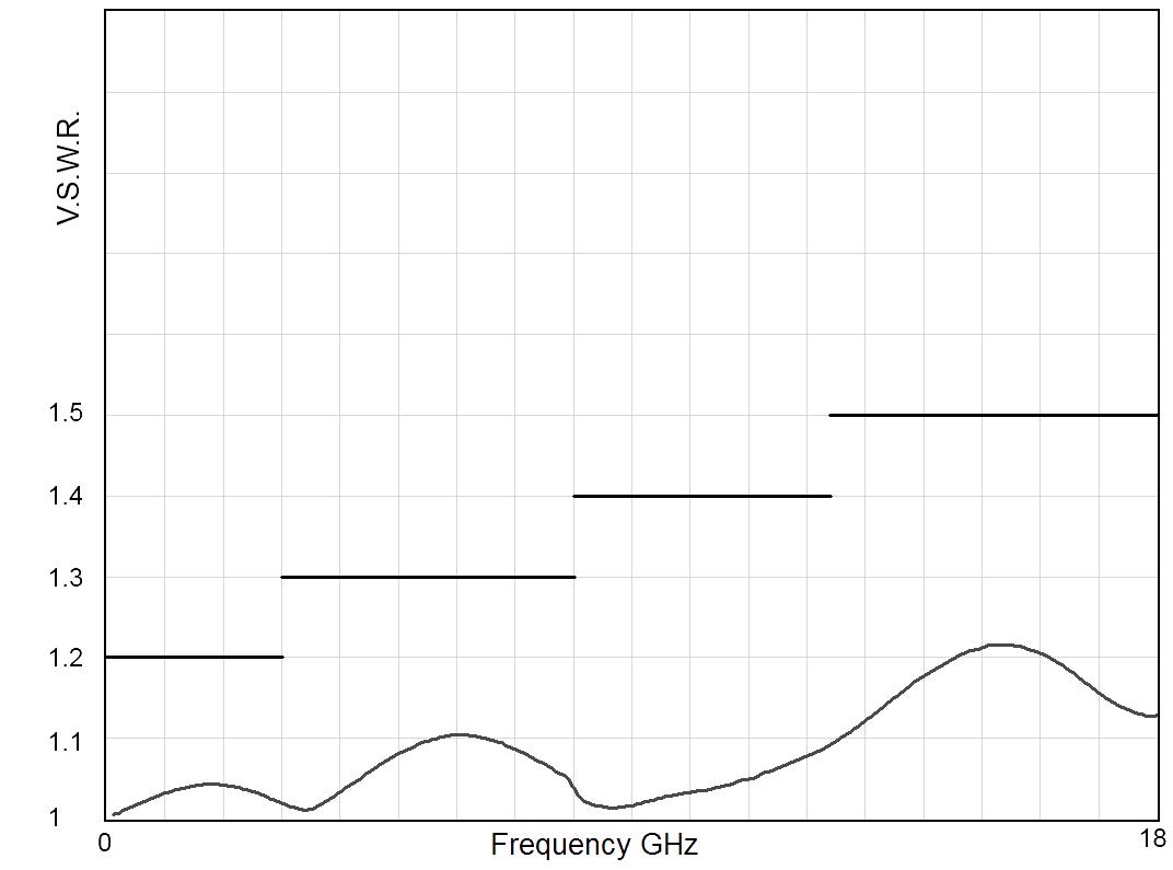
Frequency (GHz)
LOW PIM | 6-13 SIMPLIFICATION IS OUR INNOVATION Visit www.radiall.com for more information
TYPICAL OUTLINE DRAWING
Example: SPnT SMA up to 18 GHz
SOLDER PINS
Type 0 or 1 with option 0 - 1 - 3 or 4
Type 2 or 3 with option 0 or 1
SOLDER PINS
Type 0 or 1 with option 2 or 8
Type 2 or 3 with option 2 - 3 - 4 or 8
Type 4 - 5 - 8 or 9 with option 0 - 2 or 8
D-SUB CONNECTOR All models
Notes
All dimensions are in millimeters [inches].
6-14 | LOW PIM SIMPLIFICATION IS OUR INNOVATION Visit www.radiall.com for more information
Series
RAMSES
Example: SPnT N up to 12.4 GHz
RF CONNECTOR ALLOCATION
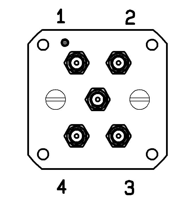
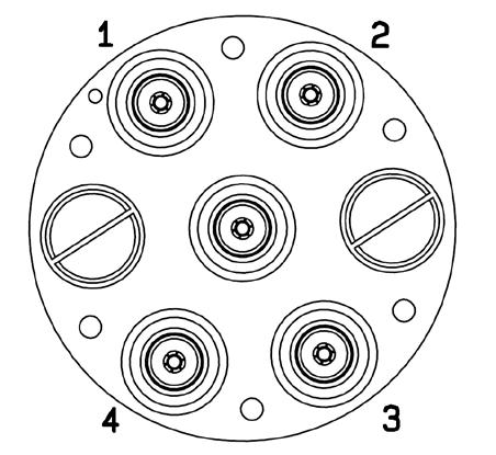
Notes
All dimensions are in millimeters [inches].
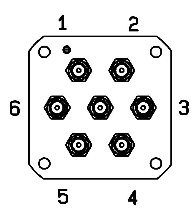
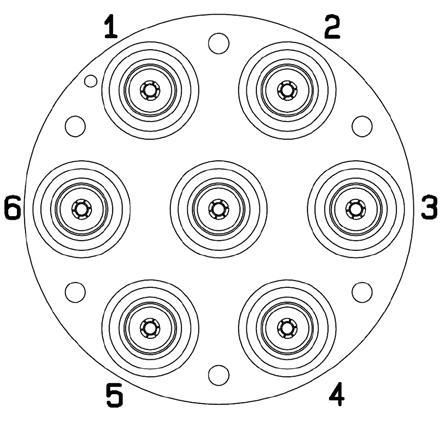
LOW PIM | 6-15 SIMPLIFICATION IS OUR INNOVATION Visit www.radiall.com for more information
N N
SP4T SMA SMA
RAMSES Series
SP6T
COAXIAL LOW PIM SWITCHES - ELECTRICAL SCHEMATICS
TYPE FAILSAFE LATCHING
Without option Without option Cut-off C+ and suppression diodes
Indicator contact Indicator contact Cut-off and I.C. C+, suppression diodes and I C
Suppression diodes Suppression diodes Cut-off and TTL Driver C+ and cut-off
Page Number
Options
Suppression diodes and I C Suppression diodes and I C Cut-off, TTL and I.C. C+, cut-off and I.C.
SPDT see page 2-20 see page 2-21 see page 2-22 see page 2-23
DPDT see page 4-10 see page 4-11 see page 4-12 see page 4-13
TYPE NORMALLY OPEN LATCHING
Without option BCD TTL driver Without option Cut-off
Indicator contact BCD TTL driver and I C Indicator contact Cut-off and I.C.
Options
Driver, Cutoff and Auto reset C+ and suppression diodes
Driver, Cutoff, Auto reset and I C C+, suppression diodes and I C
Suppression diodes C+ Suppression diodes Cut-off and Auto reset BCD TTL Driver, Cut-off and Auto reset C+, Cut-off and Auto reset
Suppression diodes and I �C � C+ and I �C � Supression diodes and I �C � Cut-off, Auto reset and I �C � BCD TTL Driver, Cut-off, Auto reset and I �C � C+, Cut-off, Auto reset and I �C �
Driver C+ and suppression diodes
6-16 | LOW PIM SIMPLIFICATION IS OUR INNOVATION Visit www.radiall.com for more information
TTL Driver TTL Driver C+TTL Driver and I C TTL Driver and I C C+
C
and I
TTL
TTL
TTL
TTL
TTL
RAMSES Series
Driver Cut-off and TTL Driver C+
Driver and I C C+, suppression diodes and I C TTL Driver and I C Cut-off, TTL and I C C+ and I CPage Number SPnT see page 5-38 see page 5-39 see page 5-40 see page 5-41 see page 5-42 see page 5-43
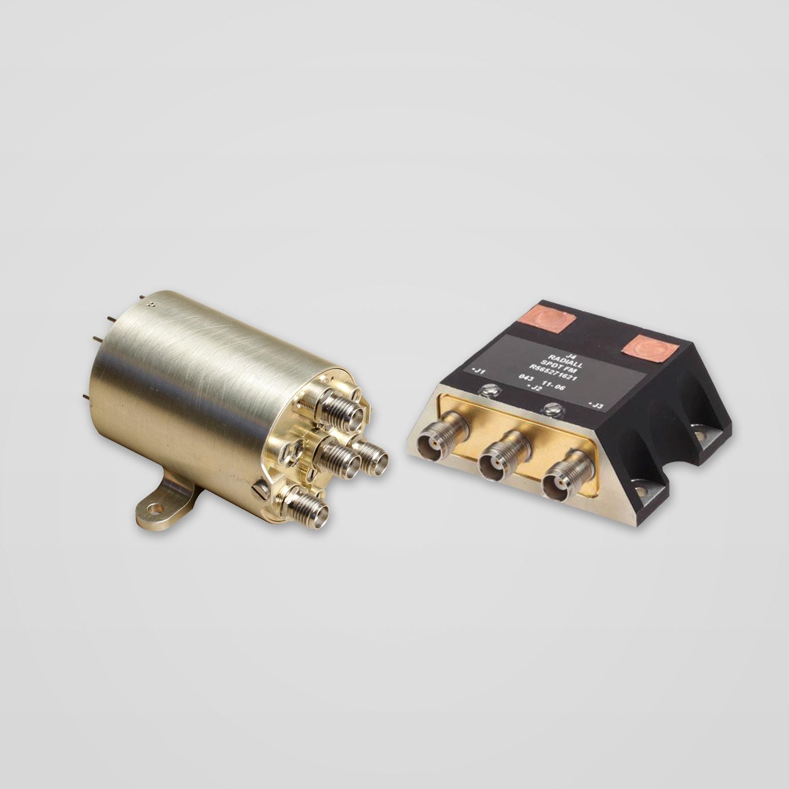
SIMPLIFICATION IS OUR INNOVATION Visit www.radiall.com for more information SECTION 7 SPACE
Section 7 Table of Contents
SIMPLIFICATION IS OUR INNOVATION Visit www.radiall.com for more information SPACE | 7-1 INTRODUCTION General Information 7-2 Radiall Specifications 7-3 FLIGHT MODELS Low Power Coaxial SPDT Switch 7-4 to 7-15 Low Power Coaxial DPDT Switch ��������������������������������������������������������������������������������������������������������������������������������������� 7-6 to 7-7 Low Power Coaxial T-Switch ��������������������������������������������������������������������������������������������������������������������������������������������� 7-8 to 7-9 Low Power Coaxial DP3T Switch ����������������������������������������������������������������������������������������������������������������������������������� 7-10 to 7-11 High Power Coaxial SPDT Switch ���������������������������������������������������������������������������������������������������������������������������������� 7-12 to 7-13 High Power Coaxial DP3T Switch ���������������������������������������������������������������������������������������������������������������������������������� 7-14 to 7-15 High Power Coaxial T-Switch ����������������������������������������������������������������������������������������������������������������������������������������� 7-16 to 7-17 THERMAL VACUUM SWITCHES FOR GROUND SEGMENTS General Information �������������������������������������������������������������������������������������������������������������������������������������������������������� 7-18 to 7-20
GENERAL INFORMATION
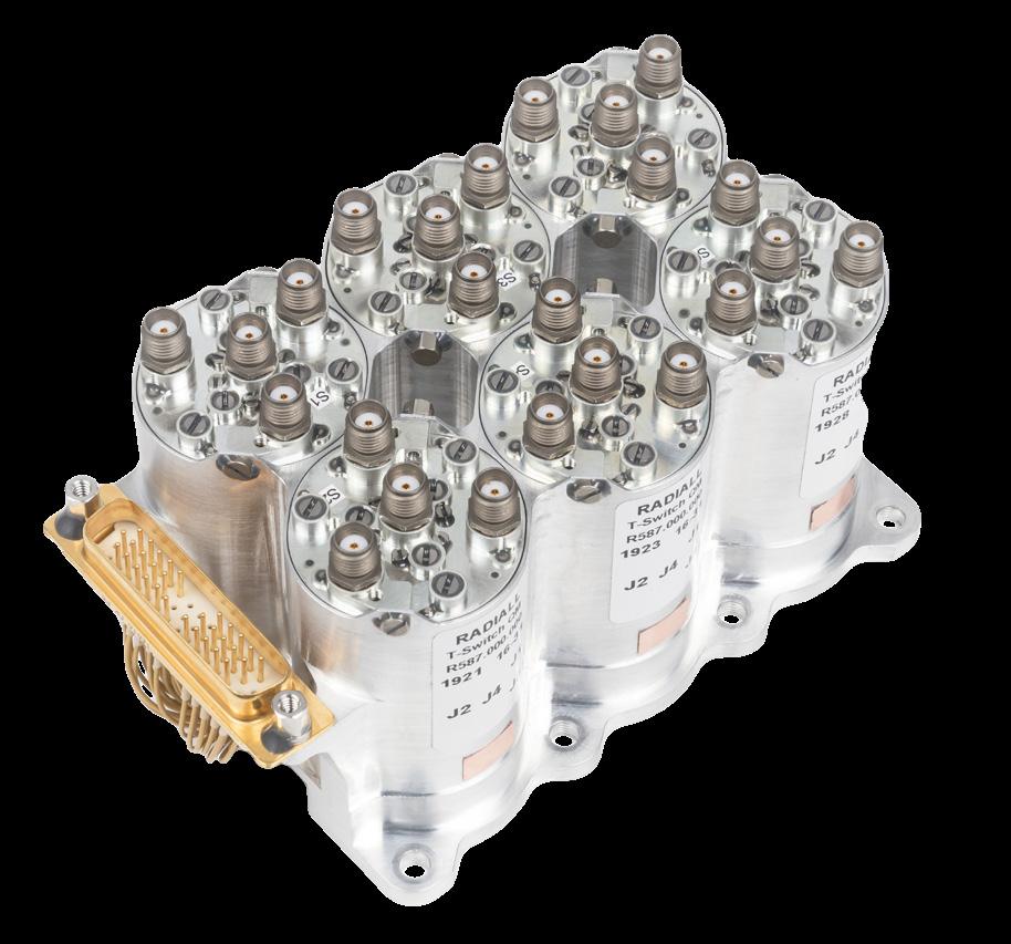
Radiall Hi-Rel switches are manufactured based on over 40 years of experience and thousands of products that have been designed, qualified, and delivered for both commercial and military applications. With a space heritage of over 25 years and products in flight on over 300 satellites around the world, Radiall guarantees the highest level of manufacturing, quality and reliability.
Radiall Hi-Rel coaxial switches have been fully evaluated and approved by the European Space Agency for Space use according to the generic specification ESCC3603. Radiall offers products tested at several levels based on the same hardware including:
- EM: Engineering Model
- QM: Qualification Model
- PFM: Proto Flight Model
Radiall also provides a full range of low cost Hi-Rel switches for space applications. These products meet the requirements for communication satellite applications according to RAD-GEN-SWIT-001 and follow detailed specifications according to the Radiall part number list (see page 7-3).
ENVIRONMENTAL CHARACTERISTICS
Operation temperature range
QUALIFICATION LEVEL
- 30°C/+ 85°C
Non operation temperature range - 40°C/+ 85°C
Vibration
Sinus
Random
5 – 100 Hz/20 g
20 – 2,000 Hz/28.57 g
Shocks - ½ sinus / 1200 g / 0.25 ms
Pressure - Free space vacuum
SIMPLIFICATION IS OUR INNOVATION Visit www.radiall.com for more information 7-2 | SPACE
Introduction
Introduction
RADIALL SPECIFICATIONS
RADIALL BEST RUNNERS PART LIST (FM P/N)
DETAIL SPECIFICATION
RAD - DET - SPDT - 001 SPDT Low power
SMA
SMA 2 9
RAD - DET - SPDT - 002 SPDT High power TNC
SMA
R571 492 601
R571 472 601
R571 471 601
R571 892 601
R571 872 601
R571 871 601
RAD - DET - DPDT - 006 DPDT Low power
RAD - DET - TSSD - 002 T-Switch Sequentiel Low power
SMA 2 9
DESIGNATION
Fixing plate with pins
Lay down with pins
Lay down with D-sub
Fixing plate with pins
Lay down with pins
Lay down with D-sub
R565 271 601 Lay down with D-sub, High Cavity
R565 371 601 Lay down with D-sub, Standard Cavity
R578 483 601
R578 472 601
R578 482 601
R578 872 601
R578 883 601
R578 882 601
SMA
SMA 2 �9
RAD - DET - TRSD - 002 T-Switch High power TNC
SMA
RAD - DET - TRSD - 003 T-Switch Random Low power
Stand up with D-sub
Lay down with pins
Stand up with pins
Lay down with pins
Stand up with D-sub
Stand up with pins
R587 432 601 Lay down with pins
R587 443 601 Stand up with D-sub
R587 442 601 Stand up with pins
R587 832 621 Lay down with pins
R587 842 621 Stand up with pins
R587 843 621 Stand up with D-sub
R588 371 601 Lay down with D-sub
R588 381 611 Stand up with D-sub
R587 492 601 Fixing plate with pins
R587 472 601 Lay down with pins
R587 482 601 Stand up with pins
R587 872 601 Lay down with pins
SMA 2 9
R587 882 601
Stand up with pins
R587 883 601 Stand up with D-sub
SMA R586 471 601 Lay down with D-sub
RAD - DET - DP3T - 001 DP3T Low power
SMA 2 9 R586 871 601 Lay down with D-sub
R564 271 601 Lay down with D-sub, High Cavity
RAD - DET - DP3T - 002 DP3T High power TNC
R564 371 601 Lay down with D-sub, Standard Cavity
R564 372 601 Lay down with pins, Standard Cavity
SIMPLIFICATION IS OUR INNOVATION Visit www.radiall.com for more information SPACE | 7-3
PRODUCT POWER CAP. CONNECTORS RADIALL
FM
P/N
Flight
Models
LOW POWER COAXIAL SPDT SWITCH
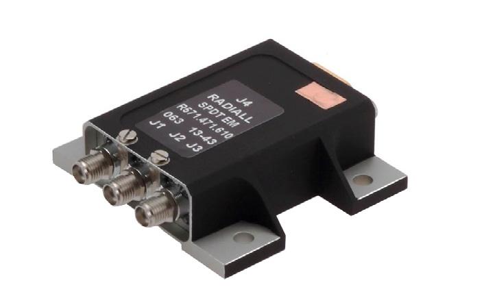
GENERAL SPECIFICATIONS
Low power latching Coaxial SPDT Switch according to Radiall specification RAD-DET-SPDT-001:
• DC to 22 GHz with SMA connectors
• Up to 31 GHz with SMA 2.9 connectors
• Telemetry circuit
• Suppression diodes
• D-Sub or solder pins
• Lay down or Fixing plate
• 44 grams and up
RF PERFORMANCE DC to 22 GHz SMA
SIMPLIFICATION IS OUR INNOVATION Visit www.radiall.com for more information 7-4 | SPACE
FREQUENCY GHZ DC - 4.2 4.2 - 10.7 10.7 - 12.75 12.75 - 14.5 14.5 - 22 Insertion Loss (max) dB 0 12 0 20 0 25 0 30 0 35 VSWR (max) Return Loss (min) (dB) 1 20 (21) 1 20 (21) 1 20 (21) 1 25 (19) 1 33 (17) Isolation (min) dB 70 65 E-Field Shielding Effectiveness (min) dBi 75 70 Ka – band SMA 2.9 FREQUENCY GHZ 17.5-21.5 21.5 - 27.5 27.5 - 31 Insertion Loss (max) dB 0� 45 0� 45 0� 50 VSWR (max) Return Loss (min) (dB) 1 33 (17 0) 1 35 (16 5) 1 40 (15 6) Isolation (min) dB 65 60 55 E-Field Shielding Effectiveness (min) dBi 70 60 Power Handling (max) W 10 5
UNIT MIN TYPICAL MAX Actuation Voltage V +22 +26 +29 Pick-Up Voltage V - - +20 � 5 Actuation Current mA - -at +29 V, +25 °C - 129 139 at +29 V, -30 °C - 164 176 at +29 V, +85 °C - 105 113 Switching Time ms - - 20 Pulse Duration ms 20 - 1,000 Coil Resistance (at +25 °C) Ω 210 225RF Contact Resistance mΩ - - 100 TLM Indicator Circuit - - -Contact Closed mΩ - - 1,000 Contact Open MΩ 10 10Contact Current mA - - 100 Coil Isolation at 500 VDC MΩ 10 -Dielectric Withstanding at 50 or 60 Hz Vrms 500 -Mass g - -Variant 001-004: SPDT, Fixing Plate, Pins - - 44 Variant 002-005: SPDT, Lay down, Pins - - 62 Variant 003-006: SPDT, Lay down, D-Sub - - 72 Torque Screws for: N m - -Fixing unit - - 2 0 DC connector 0 8 1 1 0 44 SMA connector - - 1�15
Flight Models
SCHEMATICS & DRAWINGS
SDPT, LAY DOWN, PINS:
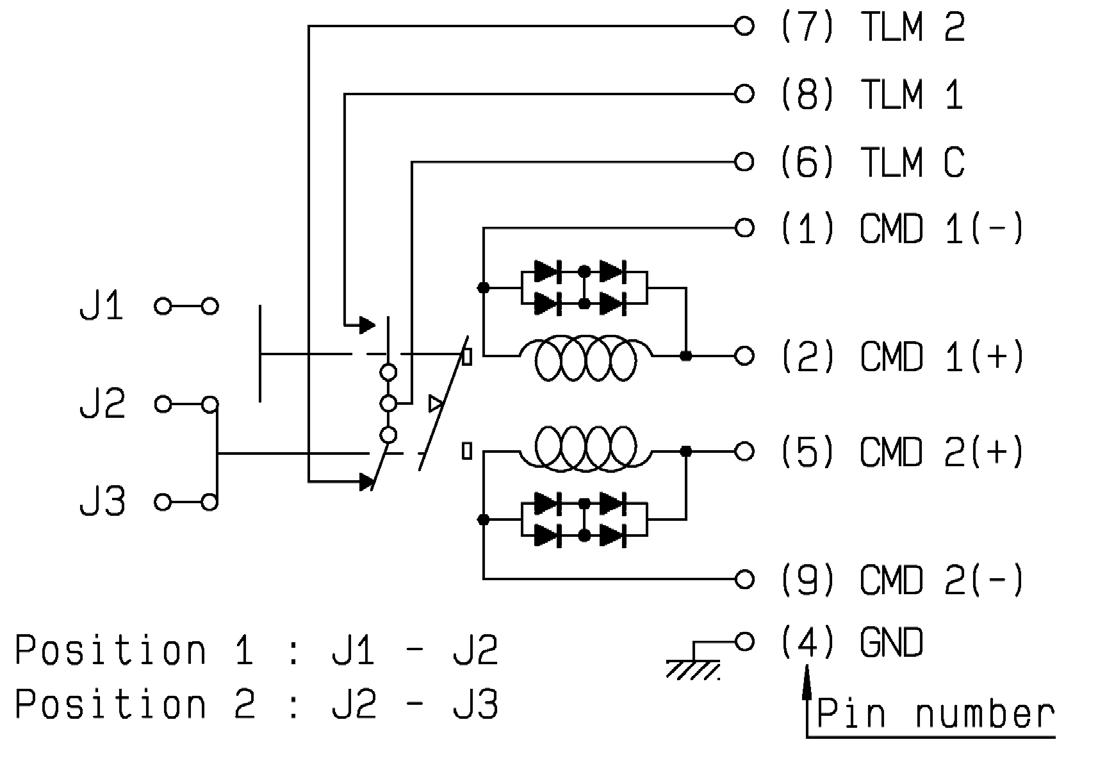
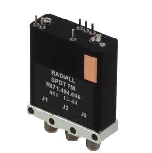
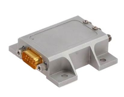
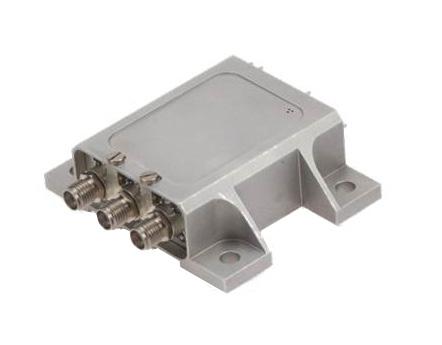
POWER DERATING GRAPH
VARIANT 001 TO 003: DC TO 22 GHz SMA
Power derating versus frequency
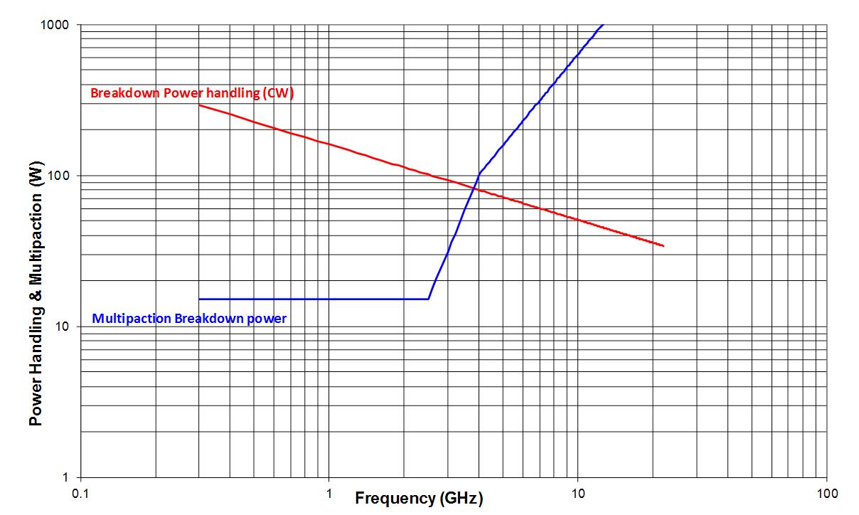
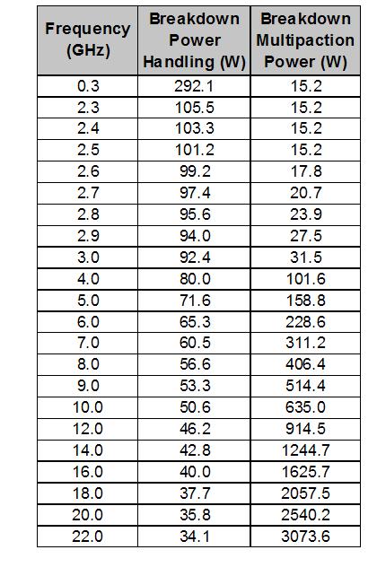
SIMPLIFICATION IS OUR INNOVATION Visit www.radiall.com for more information SPACE | 7-5
Frequency (GHz)
Power Handling & Multipaction (W)
SPDT, fixing plate with pins
SPDT, lay down with pins
SPDT, lay down with D-sub
Flight Models
LOW POWER COAXIAL DPDT SWITCH
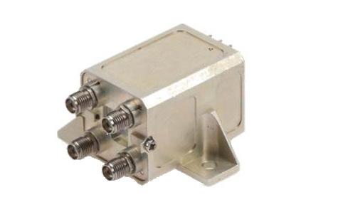
GENERAL SPECIFICATIONS
Low power latching Coaxial DPDT Switch according to Radiall specification RAD-DET-DPDT-006:
• DC to 22 GHz with SMA connectors
• Up to 31 GHz with SMA 2.9 connectors
• Telemetry circuit
• Suppression diodes
• D-Sub or solder pins
• Lay down or Stand up
• 57 grams and up
SIMPLIFICATION IS OUR INNOVATION Visit www.radiall.com for more information 7-6 | SPACE
UNIT MIN TYPICAL MAX Actuation Voltage V +22 +26 +29 Pick-Up Voltage V - - +20 � 5 Actuation Current mA - -at +29 V, +25 °C - 129 139 at +29 V, -30 °C - 164 176 at +29 V, +85 °C - 105 113 Switching Time ms - - 25 Pulse Duration ms 20 - 1,000 Coil Resistance (at +25 °C) Ω 210 225RF Contact Resistance mΩ - - 100 TLM Indicator Circuit - - -Contact Closed mΩ - - 1,000 Contact Open MΩ 10 -Contact Current mA - - 100 Coil Isolation at 500 VDC MΩ 10 -Dielectric Withstanding at 50 or 60 Hz Vrms 500 -Mass g - -Variant 001-005: C-Switch, Stand up D-Sub - - 80 Variant 002-004: C-Switch, Lay down Pins - - 57 Variant 003-006: C-Switch, Stand up Pins - - 63 RF PERFORMANCE DC to 22 GHz SMA FREQUENCY GHZ DC - 4.2 4.2 - 8.4 8.4 - 14.5 14.5 - 18 18 - 20 20 - 22 Insertion Loss (max) dB 0 15 0 25 0 30 0 40 0 50 0 50 VSWR (max) Return Loss (min) (dB) 1 20 (21) 1 25 (19) 1 25 (19) 1 33 (17) 1 33 (17) 1 40 (15 6) Isolation (min) dB 70 65 E-Field Shielding Effectiveness (min) dBi 75 70 68 65 60 Ka – Band SMA 2.9 FREQUENCY GHZ 17.5-21.5 27.5 - 31 Insertion Loss (max) dB 0 50 0 65 VSWR (max) Return Loss (min) (dB) 1 33 (17 7) 1 40 (15 6) Isolation (min) dB 65 60 E-Field Shielding Effectiveness (min) dBi 60 60 Power Handling (max) W 10 5
Flight Models
SCHEMATICS & DRAWINGS
C-SWITCH, SMA, LAY DOWN PINS:
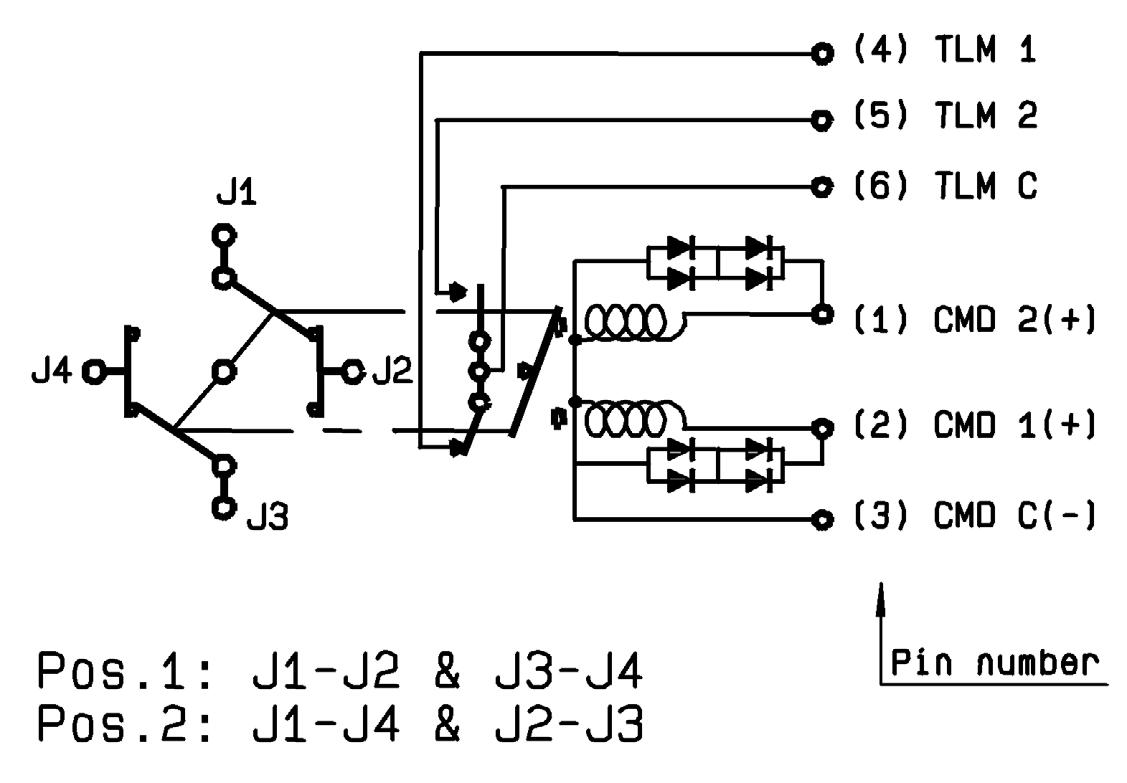
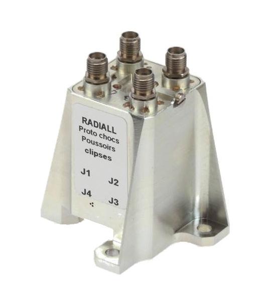
stand up with pins
POWER DERATING GRAPH
VARIANT 001 TO 003: DC TO 22 GHz SMA
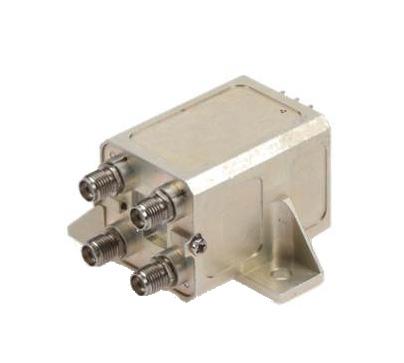
lay down with pins
Power derating versus frequency
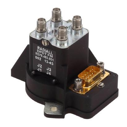
Power Handling & Multipaction (W)

Frequency (GHz)
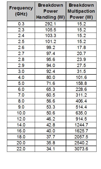
SIMPLIFICATION IS OUR INNOVATION Visit www.radiall.com for more information SPACE | 7-7
C-Switch,
C-Switch,
C-Switch, stand up with D-sub
Flight Models
LOW POWER COAXIAL T-SWITCH
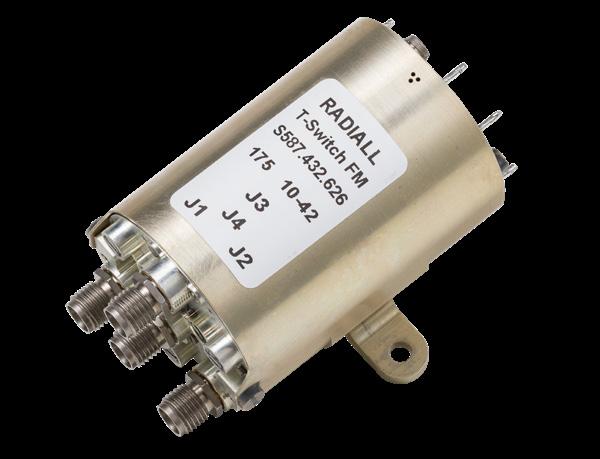
GENERAL SPECIFICATIONS
Low power latching Coaxial Switch according to Radiall specification
RAD-DET-TSSD-002 and RAD-DET-TSRD-003:
• Random or Sequential drive
• DC to 22 GHz with SMA connectors
• Up to 31 GHz with SMA 2.9 connectors
• Telemetry circuit
• Suppression diodes
• D-Sub or solder pins
• Stand up or Lay down or fixing plate
• 58 grams and up
Dielectric
Torque Screws for:
RF PERFORMANCE
DC to 22 GHz SMA
Ka – Band SMA 2.9
SIMPLIFICATION IS OUR INNOVATION Visit www.radiall.com for more information 7-8 | SPACE
FREQUENCY GHZ DC-4.2 4.2-5.5 5.5-6.6 6.6-7.7 7.7-8.8 8.8-10.5 10.5-14.5 14.5-17.8 17.8-20 20-22 Insertion Loss (max) dB 0 15 0 17 0 18 0 21 0 24 0 30 0 35 0 45 0 50 0 50 VSWR (max) Return Loss (min) (dB) 1 20 (21) 1 22 (20) 1 25 (19) 1 25 (19) 1 25 (19) 1 25 (19) 1 25 (19) 1 33 (17) 1 33 (17) 1 40 (15 6) Isolation (min) dB 70 65 E-Field Shielding Effectiveness (min) dBi 75 70 65 65
FREQUENCY GHZ 17.5-21.5 27.5 - 31 Insertion Loss (max) dB 0� 50 0�65 VSWR (max) Return Loss (min) (dB) 1 33 (17) 1 40 (15 6) Isolation (min) dB 65 60 E-Field Shielding Effectiveness (min) dBi 60 60 Power Handling (max) W 10 5
RAD
RAD
DET
TSRD - 003 Random Drive UNIT MIN TYPICAL MAX MIN TYPICAL MAX Actuation Voltage V +22 +26 +29 +22 +26 +29 Pick-Up Voltage V - - +20 5 - - +20 5 Actuation Current mA - - - - -at +29 V, +25 °C - 345 364 - 285 305 at +29 V, -30 °C - 439 462 - 365 390 at +29 V, +85 °C - 280 295 - 234 250 Switching Time ms - - 25 - - 20 Pulse Duration ms 20 - 1,000 20 - 1,000 Coil Resistance (at +25 °C) Ω 79 8 84 - 88 95RF Contact Resistance mΩ - - 100 - - 100 TLM Indicator Circuit - - - - - -Contact Closed mΩ - - 1,000 - - 1,000 Contact Open MΩ 10 - - 10 -Contact Current mA - - 100 - - 100 Coil Isolation at 500 VDC MΩ 10 - - 10 - -
- DET - TSSD - 002 Requential Drive
-
-
Withstanding at 50 or 60 Hz Vrms 500 - - 500 -Mass g - - - - -T-Switch, Lay down Pins - - 73 - - 64 T-Switch, Stand up D-Sub - - 100 - - 100 T-Switch, Stand up Pins - - 75 - - 75 T-Switch, Fixing Plate - - - - - 58
N m - - - - -Fixing unit - - 2 �0 - - 2 �0 D-sub connector 0 27 - 0 44 - - N/A RF connector 0 8 1 1 1 15 0 8 1 1 1 15
SCHEMATICS & DRAWINGS
SEQUENTIAL DRIVE
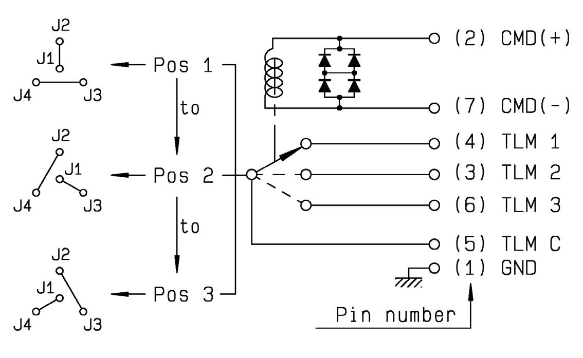
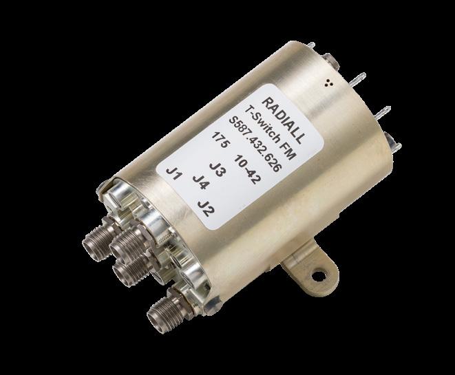
T-Switch, lay down with pins
POWER DERATING GRAPH
VARIANT 001 TO 003: DC TO 22 GHz SMA
RANDOM DRIVE
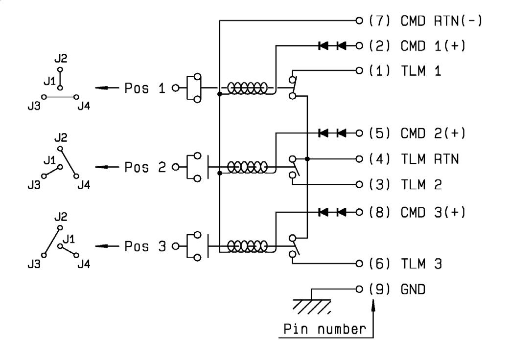
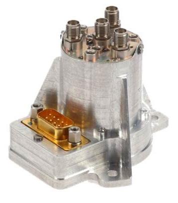
T-Switch, stand up with D-Sub
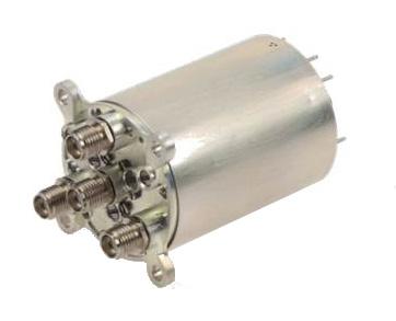
T-Switch, fixing plate with pins
Handling & Multipaction (W)
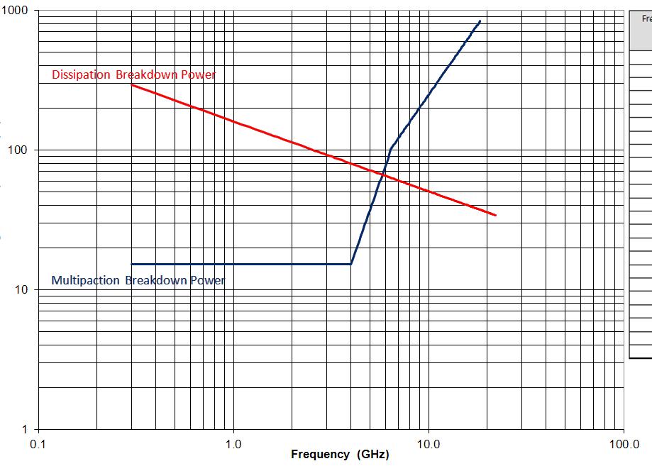
Power derating versus frequency Frequency (GHz)
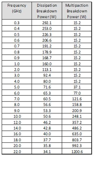
SIMPLIFICATION IS OUR INNOVATION Visit www.radiall.com for more information SPACE | 7-9
Flight Models
Power
Flight Models
LOW POWER COAXIAL DP3T SWITCH
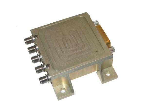
GENERAL SPECIFICATIONS
Low power latching Coaxial Switch according to Radiall specification RAD-DET-DP3T-001:
• DC to 22 GHz with SMA connectors
• DC to 31 GHz with SMA 2.9 connectors
• Telemetry circuit
• Suppression diodes
RF PERFORMANCE
DC to 22 GHz SMA
Ka – Band SMA 2.9
SIMPLIFICATION IS OUR INNOVATION Visit www.radiall.com for more information 7-10 | SPACE
FREQUENCY GHZ DC - 4.2 4.2 - 10.7 10.7 - 12.75 12.75 - 14.5 14.5 - 22 Insertion Loss (max) dB 0 12 0 20 0 25 0 30 0 35 VSWR (max) Return Loss (min) (dB) 1� 20 (21) 1� 20 (21) 1� 20 (21) 1� 25 (19) 1� 33 (17) Isolation (min) dB 70 65 E-Field Shielding Effectiveness (min) dBi 75 70
FREQUENCY GHZ 17.5-21.5 21.5 - 27.5 27.5 - 31 Insertion Loss (max) dB 0 45 0 45 0 50 VSWR (max) Return Loss (min) (dB) 1 33 (17) 1 35 (16 5) 1 40 (15 6) Isolation (min) dB 65 60 E-Field Shielding Effectiveness (min) dBi 70 60 Power Handling (max) W 10 5
UNIT MIN TYPICAL MAX Actuation Voltage V +22 +26 +29 Pick-Up Voltage V - - +20 5 Actuation Current mA - -at +29 V, +25 °C - 129 139 at +29 V, -30 °C - 164 176 at +29 V, +85 °C - 105 113 Switching Time ms - - 20 Pulse Duration ms 20 - 1,000 Coil Resistance (at +25 °C) Ω 210 225RF Contact Resistance mΩ - - 100 TLM Indicator Circuit - - -Contact Closed mΩ - - 1,000 Contact Open MΩ 10 -Contact Current mA - - 100 Coil Isolation at 500 VDC MΩ 10 -Dielectric Withstanding at 50 or 60 Hz Vrms 500 -Mass g - - 106 Torque Screws for: N m - -Fixing unit - - 2 0 D-sub connector 0 27 - 0 44 RF connector 0 8 1 1 1 15 • D-Sub • Lay
• 106 grams
down
Flight Models
SCHEMATICS & DRAWINGS
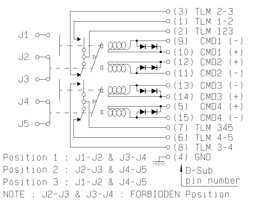
POWER DERATING GRAPH
VARIANT 001: DC TO 22 GHz SMA
Power derating versus frequency
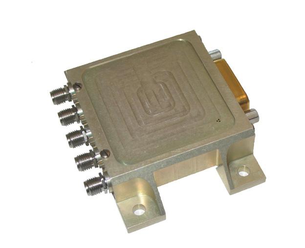
DP3T, lay down with D-sub
Power Handling & Multipaction (W)

Frequency (GHz)
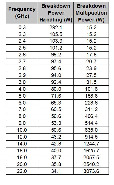
SIMPLIFICATION IS OUR INNOVATION Visit www.radiall.com for more information SPACE | 7-11
Flight Models
HIGH POWER COAXIAL SPDT SWITCH
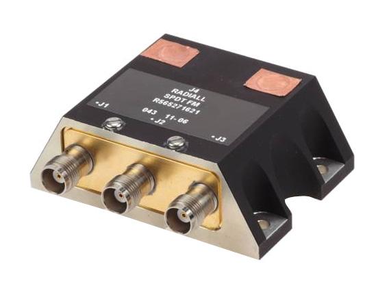
GENERAL SPECIFICATIONS
High power latching Coaxial SPDT Switch according to Radiall specification RAD-DET-SPDT-002::
• TNC connectors
• Up to 2.2 GHz, with 160 Watts CW
• Up to 4.8 GHz, with 150 Watts CW
• Telemetry circuit
• Suppression diodes
• D-Sub
• Lay down
• 275
RF PERFORMANCE
SIMPLIFICATION IS OUR INNOVATION Visit www.radiall.com for more information 7-12 | SPACE
DC - 2.2 GHz Variant 001 DC - 4.8 GHz Variant 002 FREQUENCY GHZ 0.04 -1.0 1.0 - 1.6 1.6 - 2.2 0.04 - 1.0 1.0 - 1.6 1.6 - 2.2 2.2 - 4.8 Insertion Loss (max) dB 0 12 0 12 0 22 VSWR (max) Return Loss (min) (dB) 1� 20 (20 8) 1� 20 (20 8) 1� 38 (15 9) Isolation (min) dB 70 E-Field Shielding Effectiveness (min) dBi 70 60
UNIT MIN TYPICAL MAX Actuation Voltage V +20 +26 +30 Pick-Up Voltage V - - +19 Actuation Current mA - -at +29 V, +25 °C 178 188 198 at +29 V, -30 °C 227 239 251 at +29 V, +85 °C 145 153 161 Switching Time ms - 25 35 Pulse Duration ms 50 - 1,000 Coil Resistance (at +25 °C) Ω 152 160 168 RF Contact Resistance mΩ - - 100 TLM Indicator Circuit - - -Contact Closed mΩ - - 1,000 Contact Open MΩ 2 -Contact Current mA - - 100 Coil Isolation at 500 VDC MΩ 1 -Dielectric Withstanding at 50 or 60 Hz Vrms 500 -Mass Variants 001 and 002 g - - 275 Torque Screws for: N m - -Fixing unit - - 2 0 D-sub connector 0 27 - 0 44 RF connector 1 7 - 2 65
g
Flight Models
SCHEMATICS & DRAWINGS
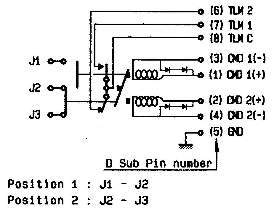
POWER DERATING GRAPH
VARIANT 001, HIGH CAVITY
Power Handling & Multipaction (W)
Power derating versus frequency
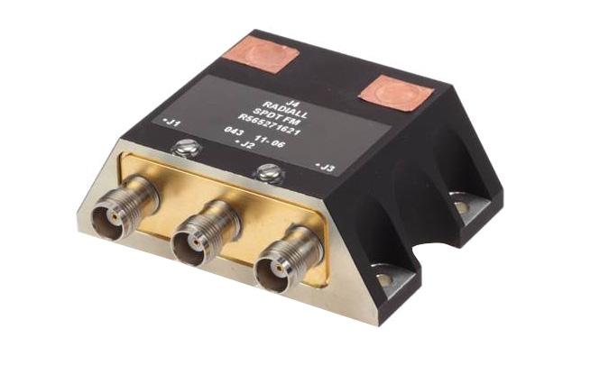
lay down with D-sub, variant 001 and 002
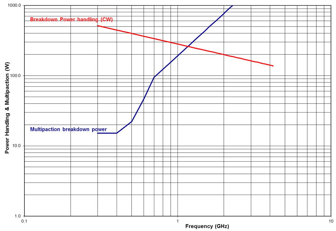
VARIANT 002, STANDARD CAVITY
Power Handling & Multipaction (W)
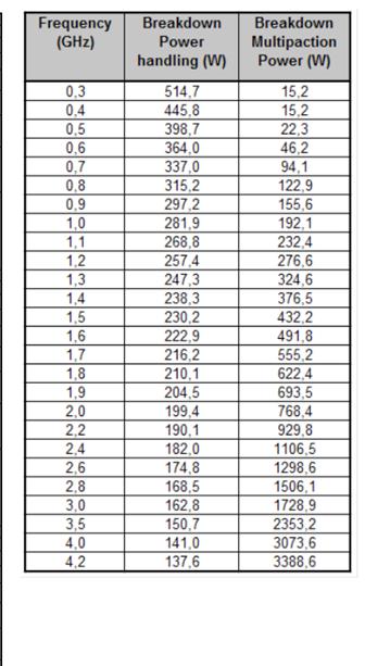
Frequency (GHz)
Power derating versus frequency
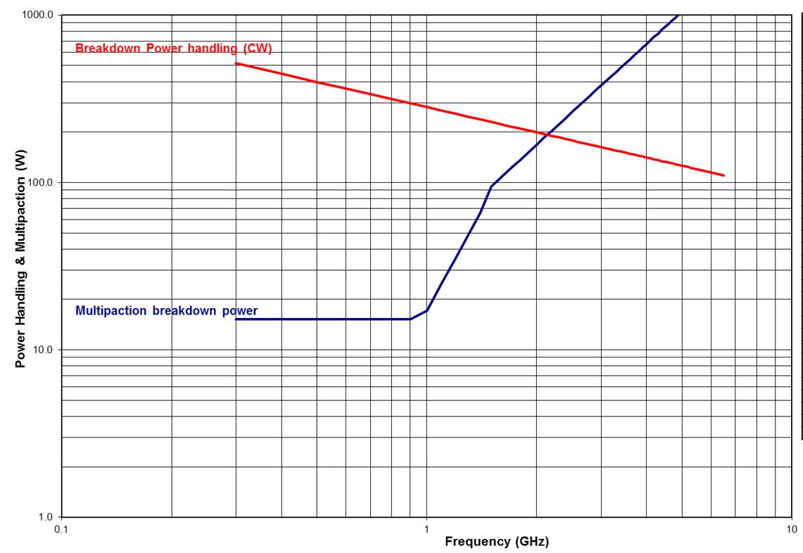
Frequency (GHz)
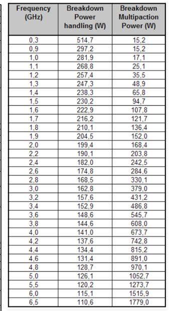
SIMPLIFICATION IS OUR INNOVATION Visit www.radiall.com for more information SPACE | 7-13
SPDT
Flight Models
HIGH POWER COAXIAL DP3T SWITCH

GENERAL SPECIFICATIONS
High power latching Coaxial DP3T Switch according to Radiall specification RAD-DET-DP3T-002:
• TNC connectors
• Up to 2.2 GHz, with 160 Watts CW
• Up to 4.8 GHz, with 150 Watts CW
• Telemetry circuit
• Suppression diodes
• D-Sub or pins
• Lay down
• 390 g and up
RF PERFORMANCE
SIMPLIFICATION IS OUR INNOVATION Visit www.radiall.com for more information 7-14 | SPACE
DC - 2.2 GHz Variant 001 DC - 4.8 GHz Variant 002 and 003 FREQUENCY GHZ 0.04 -1.0 1.0 - 1.6 1.6 - 2.2 0.04 - 1.0 1.0 - 1.6 1.6 - 2.2 2.2 - 4.8 Insertion Loss (max) dB 0 12 0 12 0 22 VSWR (max) Return Loss (min) (dB) 1 20 (20 8) 1 20 (20 8) 1 38 (15 9) Isolation (min) dB 70 E-Field Shielding Effectiveness (min) dBi 70 60
UNIT MIN TYPICAL MAX Actuation Voltage V +20 +26 +30 Pick-Up Voltage V - - +19 Actuation Current mA - -at +29 V, +25 °C 178 188 198 at +29 V, -30 °C 227 239 251 at +29 V, +85 °C 145 153 161 Switching Time ms - 25 35 Pulse Duration ms 50 - 1,000 Coil Resistance (at +25 °C) Ω 152 160 168 RF Contact Resistance mΩ - - 100 TLM Indicator Circuit - - -Contact Closed mΩ - - 1,000 Contact Open MΩ 2 -Contact Current mA - - 100 Coil Isolation at 500 VDC MΩ 1 -Dielectric Withstanding at 50 or 60 Hz Vrms 500 -Mass g - -Variant 001: Lay down D-Sub - - 460 Variant 002: Lay down D-Sub Variant - - 445 003: Lay down pins - - 390 Torque Screws for: N m - -Fixing unit - - 2 0 D-sub connector 0 27 - 0 44 RF connector 1�7 - 2 �65
Flight Models
SCHEMATICS & DRAWINGS
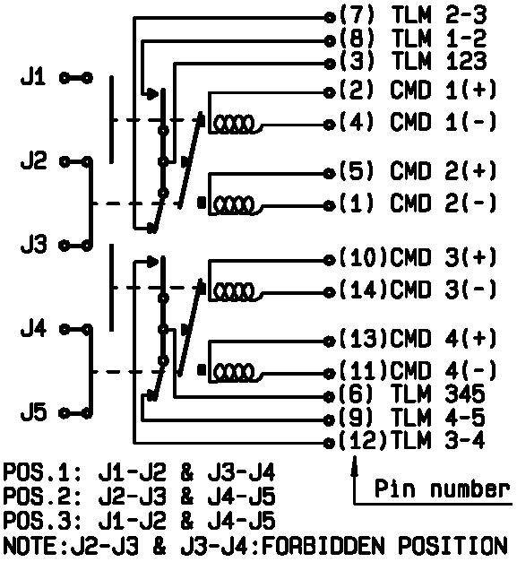
POWER DERATING GRAPH
VARIANT 001, HIGH CAVITY
Power Handling & Multipaction (W)
Power derating versus frequency
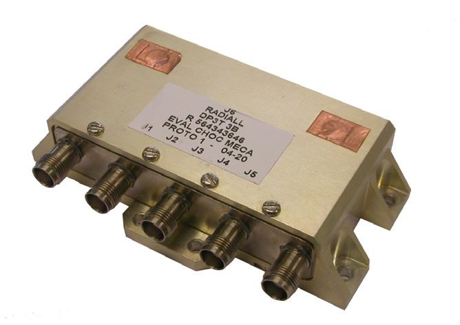
DP3T, lay down with pins

VARIANT 002, STANDARD CAVITY
Power Handling & Multipaction (W)
Frequency (GHz)
Power derating versus frequency
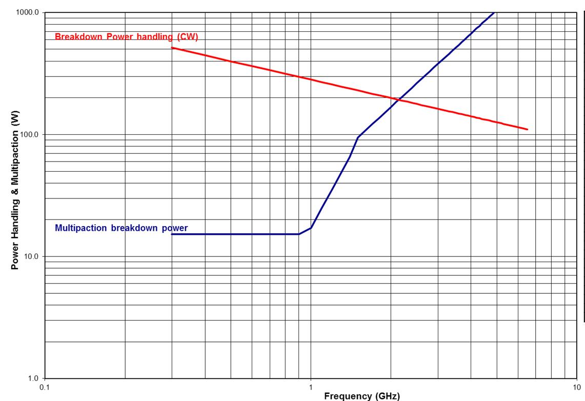
Frequency (GHz)
SIMPLIFICATION IS OUR INNOVATION Visit www.radiall.com for more information SPACE | 7-15
HIGH POWER COAXIAL T-SWITCH
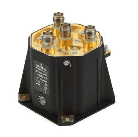
GENERAL SPECIFICATIONS
High power latching Coaxial T-Switch according to Radiall specification RAD-DET-TSRD-002:
• TNC connectors
• DC to 8 GHz
• Up to 120 Watts CW at 4 GHz
• Random Drive
• Telemetry circuit
• Suppression diodes
• D-Sub or solder pins
• Lay down or Stand up
• 355 grams and up
Variant 001: T-Switch, Lay down, D-Sub
Variant 002: T-Switch, Stand up, D-Sub
RF PERFORMANCE
DC - 8 GHz Variants 001 and 002
SIMPLIFICATION IS OUR INNOVATION Visit www.radiall.com for more information 7-16 | SPACE
FREQUENCY GHZ DC - 2 2 - 4.8 4.8 - 6 6 - 8 Insertion Loss (max) dB 0 17 0 20 0 30 0 40 VSWR (max) Return Loss (min) (dB) 1 10 (26 � 4) 1 25 (19�1) 1 35 (16 � 5) 1 50 (14) Isolation (min) dB 70 E-Field Shielding Effectiveness (min) dBi 75 70 Flight
Models
UNIT MIN TYPICAL MAX Actuation Voltage V +22 +26 +29 Pick-Up Voltage V - - +20 5 Actuation Current mA - -at +29 V, +25 °C 450 470 490 at +29 V, -25 °C 555 585 610 at +29 V, -30 °C 570 595 620 at +29 V, +80 °C 360 385 405 at +29 V, -85 °C 365 380 397 Switching Time ms - - 35 Pulse Duration ms 35 - 1,000 Coil Resistance (at +25 °C) Ω 59 3 61 8 64 4 RF Contact Resistance mΩ - - 100 TLM Indicator Circuit - - -Contact Closed mΩ - - 1,000 Contact Open MΩ 1 -Contact Current mA - - 100 Coil Isolation at 500 VDC MΩ 1 -Dielectric Withstanding at 50 or 60 Hz Vrms 500 -Mass g - - -
- - 360
- - 355
N � m - -Fixing unit - - 2 0 D-sub connector 0 27 - 0 44 RF connector 1 7 - 2 65
Torque Screws for:
Flight Models
SCHEMATICS & DRAWINGS
T-SWITCH, TNC, D-SUB, VARIANT 001 & 002:
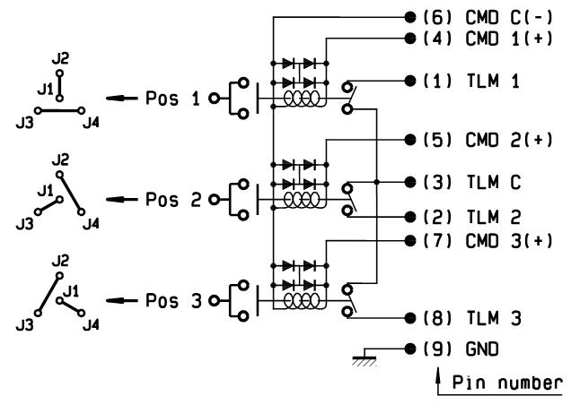
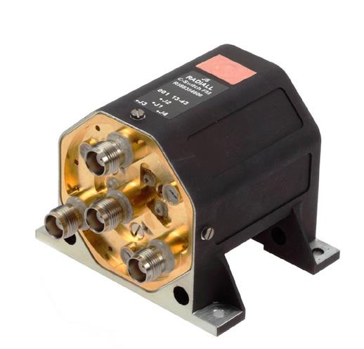
T-Switch, Lay down with D-sub, variant 001
POWER DERATING GRAPH
Power Handling & Multipaction (W)
Power derating versus frequency
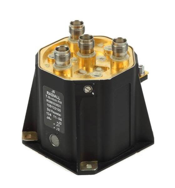
T-Switch, Stand up with D-sub, variant 002
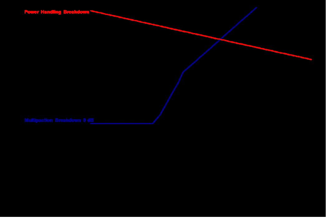
Frequency (GHz)
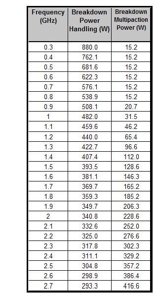
SIMPLIFICATION IS OUR INNOVATION Visit www.radiall.com for more information SPACE | 7-17
Thermal Vacuum Switches for Ground Segments
GENERAL INFORMATION
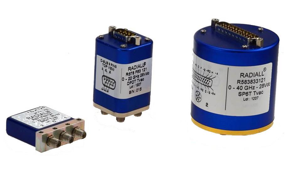
PART NUMBER SELECTION
With more than 25 years of experience in the space industry, Radiall has developed a product offering that emphasizes reliability and performance. The latest addition to the range includes SPDT, DPDT and SPnT RF switches designed to operate in thermal vacuum environments. These products can be mounted on ground based test benches, used in test equipment, and space vacuum conditions.
Tvac Series switches are designed in accordance with our standard RAMSES product offering and offer identical configurations with excellent performance
"6 standard models are available for test benches dedicated to space equipment in Thermal Vacuum environments"
• 22 GHz SPDT coaxial switch: R571 F63 121
• 22 GHz DPDT coaxial switch: R578 F63 121
• 22 GHz non-terminated SP6T coaxial switch: R583 F33 121
• 40 GHz SPDT coaxial switch: R571 863 121
• 40 GHz DPDT coaxial switch: R578 863 121
• 40 GHz non-terminated SP6T coaxial switch: R583 833 121
OPERATING MODE
Nominal operating voltage (across operating temperature)
28 (24/30) Coil resistance (+/-10%)
Nominal operating current at 23°
Average power (Thermal vacuum condition)
Switching time (max)
- SMA 2 9
Notes
and SP6T: 225 / SPDT: 350
and SP6T: 125 / SPDT: 80
See power rating chart on page 7-20
and DPDT: 10 ms / SP6T: 15 ms
10 million cycles SMA - SMA 2 9
SMA - SMA 2 �9
2 5 million cycles
5 million cycles / 2 million cycles
Connectors [1] SMA / SMA 2 9
Terminated models are also available SPnT models are only available with separated reset option 1. Connector SMA 2.9 is equivalent to "K connector ®", registered trademark of Anritsu.
SIMPLIFICATION IS OUR INNOVATION Visit www.radiall.com for more information 7-18 | SPACE
LATCHING
Vdc
Ω
DPDT
mA
DPDT
SPDT
SMA
SPDT
DPDT
SP6T
Thermal Vacuum Switches for Ground Segments
ADDITIONAL SPECIFICATION
DPDT
SP6T
SMA CONNECTOR
Male 9 pins D-Sub connector
Male 25 pins D-Sub connector
Operating temperature range -40 °C to 85 °C
Storage temperature range -55 °C to 85 °C
Construction
SMA 2.9 CONNECTOR
WHY
A
THERMAL VACUUM TEST BENCH?
• It limits the need of hermetic adaptors and cable assemblies
• It improves RF performance
• It decreases the complexity of the Test bench
Notes
1. Average power at 25 °C per RF path / Sea level.
Thermal vacuum compatible
SIMPLIFICATION IS OUR INNOVATION Visit www.radiall.com for more information SPACE | 7-19
SWITCH MODEL FREQUENCY RANGE GH z V.S.W.R. (MAX) INSERTION LOSS (MAX) d B ISOLATION (MIN) dB IMPEDANCE Ω AVERAGE POWER [1] W REPEATABILITY SPDT DC – 22 DC - 3 1 20 0 20 80 50 240 0.03 dB peak change in Insertion Loss over 100 cycles 3 - 8 1 30 0 30 70 150 8 - 12 4 1 40 0 40 60 120 12 � 4 - 18 1� 50 0� 50 60 100 18 - 22 1�70 0�70 55 40 DPDT SP6T (nonterminated) DC – 22 DC - 3 1 20 0 20 80 50 240 3 - 8 1 30 0 30 70 150 8 - 12 4 1 40 0 40 60 120 12 4 - 18 1 50 0 50 60 100 18 - 22 1 70 0 70 50 40
SWITCH MODEL FREQUENCY RANGE GH z V.S.W.R. (MAX) INSERTION LOSS (MAX) d B ISOLATION (MIN) dB IMPEDANCE Ω AVERAGE POWER [1] W REPEATABILITY SPDT DPDT DC – 40 DC - 6 1 30 0 30 70 50 80 0.03 dB peak change in Insertion Loss over 100 cycles 6 - 12 4 1 40 0 40 60 60 12 4 - 18 1 50 0 50 60 50 18 - 26 5 1 70 0 70 55 20 26 5 - 40 1 90 0 90 50 10 SP6T (nonterminated) DC – 40 DC - 6 1 30 0 30 70 50 40 6 - 12 � 4 1� 40 0� 40 60 30 12 4 - 18 1 50 0 50 60 25 18 - 26 5 1 70 0 70 55 15 26 5 - 40 1 90 0 90 50 5
POLARITY POSITIVE COMMON
Actuator terminals SPDT Solder Pins
Thermal
Vacuum Switches for Ground Segments
POWER DERATING GRAPH
SPDT, DPDT AND SP6T SMA 22 GHz
Multipactor and Power handling under vacuum (max value)
MultipactorPower handling (W) Frequency (GHz)
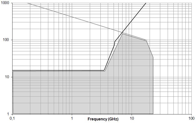
DPDT SMA 2.9 40 GHz
Multipactor and Power handling under vacuum (max value)
MultipactorPower handling (W)
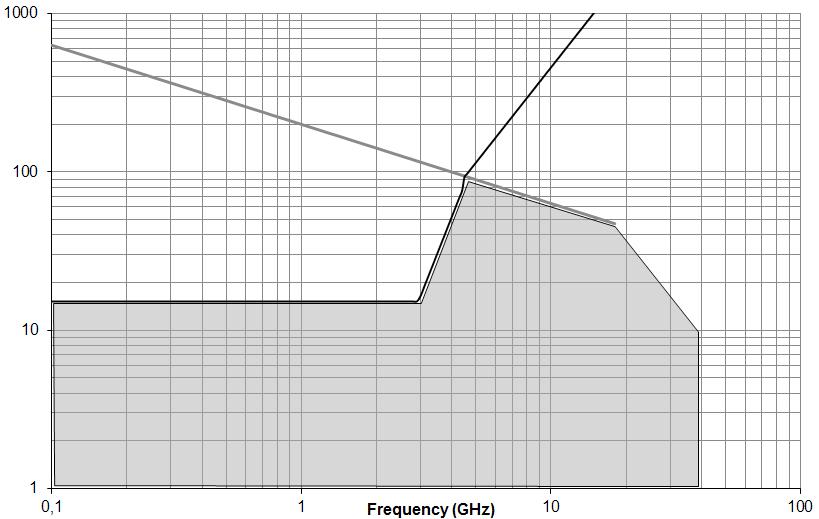
HERMETIC FEMALE/FEMALE ADAPTATORS
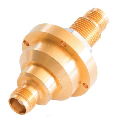
SPDT SMA 2.9 40 GHz
Multipactor and Power handling under vacuum (max value)
Multipactor
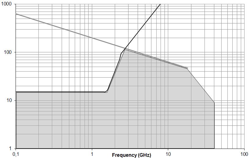
SP6T SMA 2.9 40 GHz
Multipactor and Power handling under vacuum (max value)
Multipactor
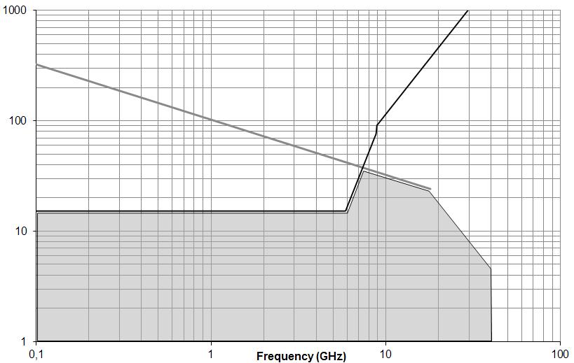
POWER HANDLING
MULTIPACTOR
AVER. POWER CAPABILITY
SIMPLIFICATION IS OUR INNOVATION Visit www.radiall.com for more information 7-20 | SPACE
Power handling (W) Frequency (GHz)
Frequency
(GHz)
Frequency
threshold - -L Band 2 GHz >2000 Wpp Max tested values, pulse width 20 µs; PRF 1,000 Hz C Band 8 GHz >2000 Wpp Power
- -L
GHz 600 WCW -
GHz 400 WCW -
•
Power handling (W)
(GHz) Multipactor
handling
Band 2
C Band 8
•SMA DC - 18 GHz •VHP TNC DC - 8 GHz • E SA qualified
High reliability
SECTION 8
OTHER
SIMPLIFICATION IS OUR INNOVATION Visit www.radiall.com for more information OTHER | 8-1
OTHER COMPONENTS RF and Microwave Coaxial Products 8-2 to 8-3 TestPro Cable Assemblies ������������������������������������������������������������������������������������������������������������������������������������������������������� 8-4 Space Qualified Products 8-5 to 8-6 Switch Applications ������������������������������������������������������������������������������������������������������������������������������������������������������ 8-7 to 8-8
Section 8 Table of Contents
Other Components
RF & MICROWAVE COAXIAL PRODUCTS
GENERAL INFORMATION
Specialized in passive RF & Microwave components, Radiall's engineering staff develops and manufactures a wide range of other coaxial standard devices including: terminations, attenuators, coaxial couplers, detectors, rotary joints, filters, and phase shifters. This range covers a wide frequency spectrum from DC to 50 GHz for telecom, aerospace, instrumentation and military application�
Radiall introduced TestPro cable assemblies into the market for Test & Measurement applications, in order to meet customers' needs
For Space applications, Radiall also offers a full range of space components built according to ESA specifications including; attenuators, terminations, couplers, connectors, coaxial cable assemblies (flexible or semi-rigid cables) for L, S, C, X, Ku and Ka band applications �
TERMINATIONS
Radiall's range of terminations is intended to terminate a coaxial transmission through characteristic impedance and dissipating the RF incident power. The main features of our full range of terminations include:
• Power range from 0.5 W to 1000 W
• Frequency from DC up to 50 GHz
• 50 Ω Impedance
• High repeatability
• Compatibility with Broad type connections: BMA, BNC, QMA, QN, N, SMA, SMA 2�9, SMB, SMP, SSMA, TNC, 1�0/2� 3, 7/16, 2� 4 mm
• Connector interface according to applicable MIL, DIN, NF and CEI
• Dedicated range for Test & Measurement with the lowest VSWR
ATTENUATORS
Attenuators are linear passive transition line components designed to be inserted between two coaxial lines to reduce the input power in a matched system by a predetermined ratio. This ratio is expressed in logarithmic terms. 3 dB as a power ratio is 2, 6 dB is 4, 20 dB is 100, and 30 dB is 1,000. The main features of our full range of coaxial attenuators include:
• Power range from 1 W to 100 W
• Frequency from DC up to 40 GHz
• High repeatability
• 50 Ω Impedance
• Compatibility with Broad type connections : BNC, QN, N, SMA, SMA 2.9, SMB, TNC, 7/16
• Connector interface according to applicable MIL, DIN, NF and CEI
• Dedicated range for Test & Measurement with the lowest VSWR
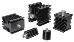
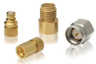
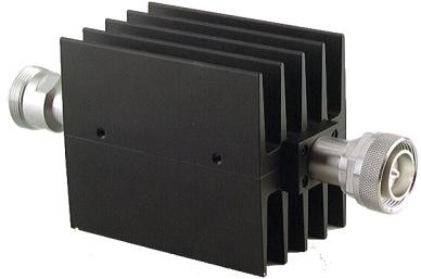
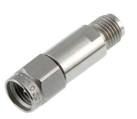
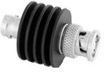
SIMPLIFICATION IS OUR INNOVATION Visit www.radiall.com for more information 8-2 | OTHER
Other Components
COAXIAL COUPLERS
Radiall's coaxial couplers offer a reliable design to meet the needs of microwave applications. The main features of our full range of coaxial couplers include:
• Directional and 3dB Hybrid 90° couplers
• Power range from 50 to 500 Watts
• Frequency from 0.15 GHz to 8 GHz
• 6, 10, 20 and 30 dB coupling factors
• SMA, Type N offered, TNC 7/16
• Dedicated range providing flat frequency response
• Possibility to design custom coaxial couplers as per customer requirements
SPECIAL MICROWAVE COMPONENTS
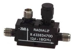
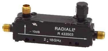
Radiall offers a complete range of special Microwave components suitable for applications utilizing the following devices:
• Feedthrough terminations
• Detectors
• Rotary joints
• DC Blocks
• Monitor tees
• Signal samplers
• Phase shifters
• Filters
Feed through terminations
These components are used to properly terminate a transmission line while testing with a high impedance measuring system such as an oscilloscope input.
Detectors
A detector is a two port device capable of supplying a low frequency signal on its output port (video), of a level proportional to the RF power applied to its input port.
Rotary joints
These components provide the transition between two coaxial transmission lines that rotate while maintaining necessary RF characteristics
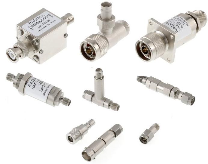
DC blocks
DC blocks are composed of a capacitor inserted to the central conductor of the coaxial line� They block any DC or low frequency current present in the line.
Signal samplers
These devices are used to sample part of an RF signal from a coaxial line They are not directive, and the sample incident reflects energy.
Phase shifters
These components create a mechanical adjustable phase shift by variation in the physical length of the transmission line
SIMPLIFICATION IS OUR INNOVATION Visit www.radiall.com for more information OTHER | 8-3
Other Components
TESTPRO CABLE ASSEMBLIES
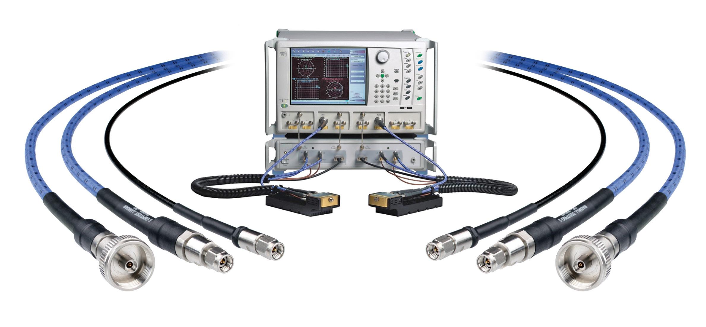
TestPro cables are dedicated to bench test cable assemblies. Our TestPro range differs from the SHF range, because the cables and connectors are designed for high performance and testing and measurement.
While others propose cosmetic solutions to appear more robust without any real performance advantages, Radiall’s design offers a full range of test bench cables that performs better than any other product on the market.
Test cable assemblies are intended for daily use in component and assembly shops, test labs and automatic test equipment applications. They differ from standard cable assemblies in that they are specifically designed for applications that require repeated connect/disconnect procedures, strenuous flexing situations and applications where cable and connector durability is important.
Key characteristics of the TestPro range include:
• Rugged interface: 5,000 mating/unmating lifecycle
• Flex life: over 20,000 cycles
• High flexibility
Notes
Please refer to TestPro catalog D1A295TE.
• Outstanding phase and loss stability for long calibration intervals
SIMPLIFICATION IS OUR INNOVATION Visit www.radiall.com for more information 8-4 | OTHER
TESTPRO 4.2 TESTPRO 3 TESTPRO 2 Frequency DC - 18 GHz DC - 26 5 GHz / DC- 40 GHz DC – 50 GHz / DC – 67 GHz Impedance 50 Ω ± 2 Ω 50 Ω ± 1 Ω 50 Ω ± 1 Ω IL (dB/m) 2 10 at 18 GHz 2 41 at 26 5 GHz - 3 11 at 40 GHz 5 00 at 50 GHz – 5 92 at 67 GHz Test IL (dB/ft) 0 64 at 18 GHz 0 73 at 26 5 GHz - 0 94 at 40 GHz 1 52 at 50 GHz – 1 80 at 67 GHz Phase with flexure stability 2° at 18 GHz 2° at 26 � 5 GHz - 5° at 40 GHz 6° at 50 GHz - 8° at 67 GHz Amplitude stability (dB) 0 05 at 18 GHz 0 05 at 40 GHz 0 05 at 50 GHz Shielding Effectiveness -110 dB min at 1 GHz -100 dB min at 1 GHz -100 dB min at 1 GHz Crush resistance 135 lb / linear in 260 lb / linear in 260 lb / linear in Minimum bend radius 25 mm (1 in ) 25 mm (1 in ) 25 mm (1 in) Temperature (°C) -55 / + 125 °C -55 / + 125 °C -55 / + 125 °C
SMA, N, TNC, PC7 SMA 3 5, SMA 2 9, NMD 2 9, TVAC 2 9, SMA 2 4 mm, N 2 4 mm/1 85 mm Flexure life cycle 10,000 20,000 20,000 Mating cycles durability 5,000 5,000 5,000 Armor Available Integrated Integrated RoHS/REACH
Yes Yes
Connectors
Yes
Other Components
SPACE QUALIFIED PRODUCTS
COAXIAL CONNECTORS
Full range of coaxial connectors operating up to Q band.
• SMA, SMA 2.9 and Very High Power TNC interfaces ESCC QPL:
• Qualified according to ESCC 3402 specifications by European Space Agency (ESA)
• TNC and SMP interfaces classified EPPL: ESA Preferred Part List
Radiall has expanded the SMP range to include, SMP-LOCK® connectors featuring a robust locking mechanism. Qualified for space applications, this new interface is the best solution when size, weight, security and high RF performance are required.
This new interface is compatible with most of Radiall products below.
• 2� 4 mm interface up to 50 GHz
LOW LOSSES CABLE ASSEMBLIES
Space qualified low loss flexible coaxial cable assemblies up to 40 GHz
• Available connectors: SMA, SMA 2.9, TNC, Very High Power TNC (ESA QPL), SMP or SMP-LOCK®
SEMI-RIGID CABLE ASSEMBLIES
Space qualified semi-rigid coaxial cable assemblies up to 40 GHz
• Available connectors: SMA, SMA 2.9, TNC, Very High Power TNC, SMP or SMP-LOCK®
COUPLERS & POWER DIVIDERS
Space qualified passive couplers DC-22 GHz and power dividers DC-31 GHz
• Admissible power up to 200 WCW
• Available connectors: SMA, SMA 2 9 and TNC
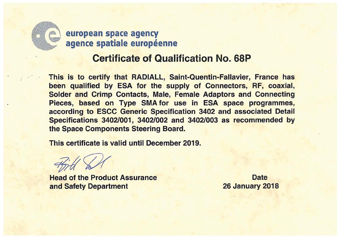

SIMPLIFICATION IS OUR INNOVATION Visit www.radiall.com for more information OTHER | 8-5
Other Components
COAXIAL SWITCHES
A full range of lightweight Space qualified switches operating up to the Ka band
• SPDT, DPDT, DP3T and T-Switch configurations available
• Available connectors: SMA, SMA 2�9 and TNC
TERMINATIONS
Range of low power coaxial loads up to 40 GHz and ESA qualified (European Space Agency).
• Available connectors: SMA, SMA 2�9, SMP, SMP LOCK® and TNC interface�
ATTENUATORS
Range of low power coaxial attenuators DC - 40 GHz and qualified by European Space Agency (ESA).
• Available connectors: SMA, SMA 2�9 and SMP LOCK® interface�
• Attenuation 0 to 30 dB �
PHASE SHIFTERS
These components create a mechanical adjustable phase shift by variation in the physical length of the transmission line up to 22 GHz.
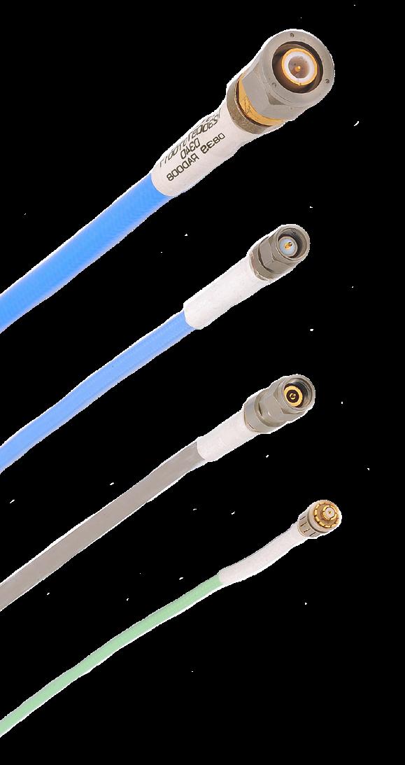
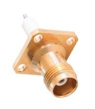
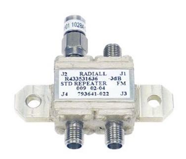
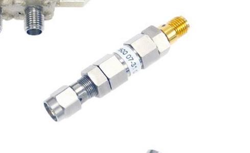
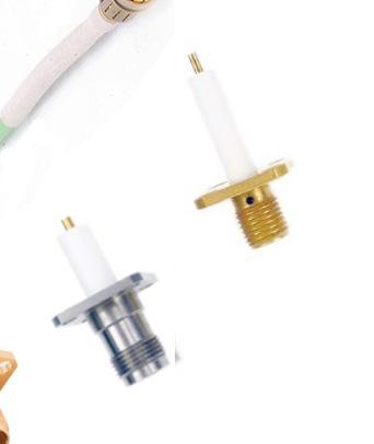
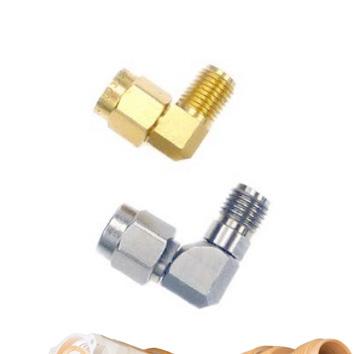
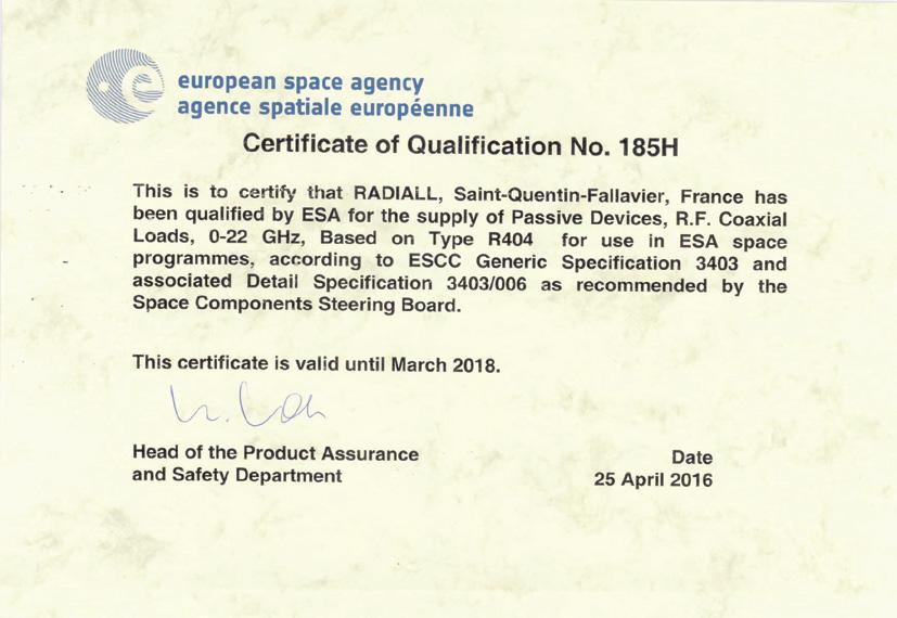
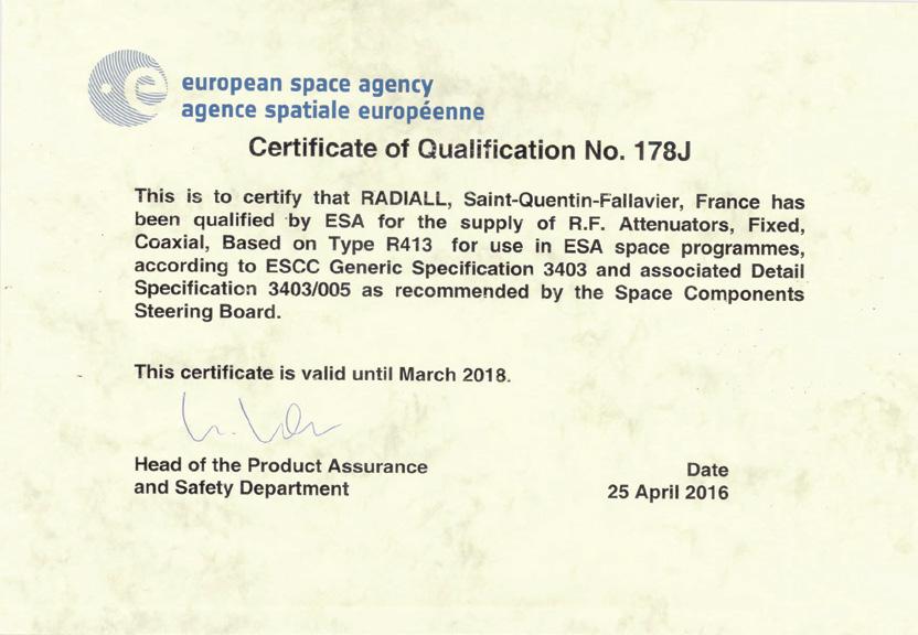
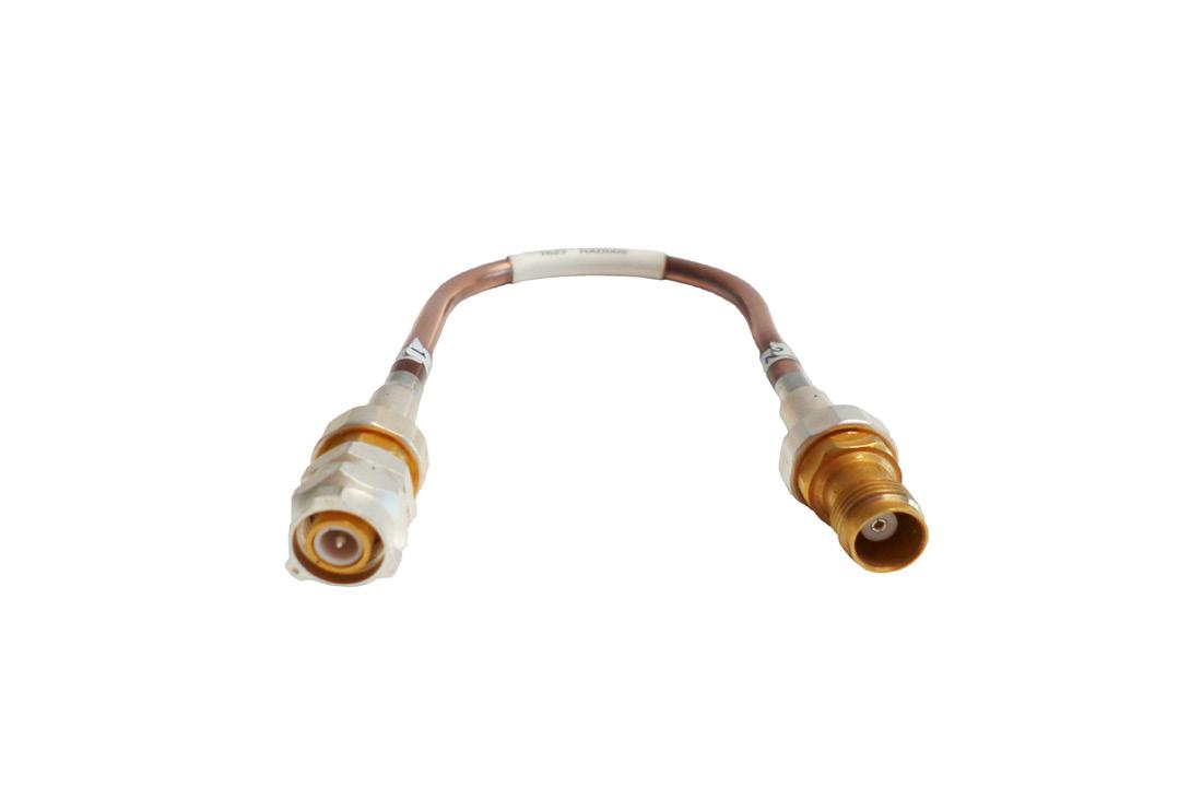
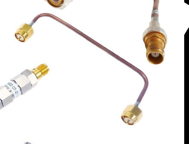
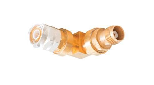
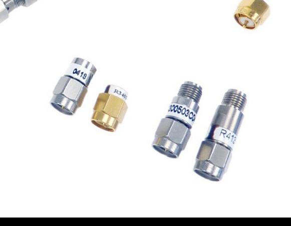
SIMPLIFICATION IS OUR INNOVATION Visit www.radiall.com for more information 8-6 | OTHER
Other Components
SWITCHES APPLICATIONS
COAXIAL TRANSFER SWITCHES (DPDT)
A DPDT is Double Pole Double Throw switch that provides two independent pairs of RF paths that are actuated simultaneously. The transfer switch is a modified DPDT device, whereas a true DPDT switch is a six port device that contains completely independent transmission paths
In a transfer switch, two transmission paths are not completely independent as shown below:
Examples of transfer switch applications: R577 RAMSES, R593 Platinum or R513 Titanium series can be selected for this application�
REDUNDANCY OF TWO TRANSMITTERS
Active transmitters are connected directly to the antenna� A second transmitter is terminated to a medium power termination and put in stand by position; ready to switch to the antenna in case of a failure of the active transmitter This is done to create redundancy for antenna maintenance
TWO TRANSMITTERS TO TWO ANTENNAS
For better signal diversity, two antennas are alternately connected to either of the two transmitters.
SIMPLIFICATION IS OUR INNOVATION Visit www.radiall.com for more information OTHER | 8-7
TRANSFER
DPDT
Other Components
COAXIAL TRANSFER AS A BYPASS SWITCH FOR CIRCUIT INSERTION APPLICATIONS
A full RF or microwave passive circuit or circuit element as a filter can be inserted into a coaxial transmission line by using a transfer switch. This element is shortened by a transfer blade in through position.
OTHER RF ARRANGEMENTS FOR A BYPASS FUNCTION
• Two SPDT switches configured to operate as a bypass switch.
• R570 RAMSES, R596 (Surface Mount Technology) or R595 PLATINUM series can be used to achieve a bypass function.
A more basic option, SPDT (Single Pole Double Throw) can be used to perform a bypass switch function. The advantage of using two SPDT relays instead of a transfer switch is a possible reduction in total package size. Generally, the use of two SPDT creates a higher isolation than a transfer switch.
A DP3T SWITCH CONFIGURED TO OPERATE AS A TRANSFER SWITCH
A R585 RAMSES or R595 Platinum series can be selected to insert a passive or active component or circuit in a RF or microwave line.
An active component as an amplifier can be inserted in a microwave line; this amplifier is connected to a 50 Ohm termination (as a booster in stand-by status) when not inserted in the main coaxial line.
SIMPLIFICATION IS OUR INNOVATION Visit www.radiall.com for more information 8-8 | OTHER
SECTION 9
NAVIGATOR
Coaxial Switches Navigator
SIMPLIFICATION IS OUR INNOVATION Visit www.radiall.com for more information 9-1 | NAVIGATOR Family Series RF Type (Switch Configuration) Frequency [1] Connector Type Number of Connector Ports Actuator Type Actuator Voltage Indicator Circuit TIL Drive Self Cut-off = If Latching Diodes Repeatabiliy Guarantee (dB) RF Terminated IL = Internal loads EL = External loads Life Cycles (Million) 2.5 GHz 3 GHz 6 GHz 8 GHz 12.4 GHz 18 GHz 20 GHz 22 GHz 26.5 GHz 40 GHz 50 GHz Normally Open Latching Failsafe RAMSES R573 & R574 SPnT J 2 � 4 mm 4 or 6 ways n n - 12/28 n n n nIL 28 SMA 2 9 3 - 6 ways n n - 12/28 n n nIL 23 4 or F F◊ F SMA 3 - 8 ways 12 ways 10 ways ◊ n n - 12/28 n n nIL 2 - 5 E QMA 3 - 6 ways n n - 12/28 n n n - - 5 9 DIN 1 6/5 6 [2] 3 - 6 ways n n - 12/28 n n n - - 2 0 1¤ 1 N 3 - 6 ways 7 - 12 ways¤ n n - 12/28 n n n - IL 2 2 BNC 3 - 6 ways n n - 12/28 n n n - - 2 5 6 TNC 3 - 6 ways n n - 12/28 n n n - - 2 R570 SPDT J 2 4 mm 3 ports - n n 12/28 n n n n - - 2 8 SMA 2 9 3 ports - n n 12/28 n n n n - - 10 3 4 F SMA 3 ports - n n 12/28 n n n n - - 10 E QMA 3 ports - n n 12/28 n n n n - - 10 9 DIN 1 6/5 6 [2] 3 ports - n n 12/28 n n n n - - 5 A PC Board Mount 3 ports - n n 12/28 n n n n - - 5 0 1 N 3 ports - n n 12/28 n n n n - - 2 5 5 6 D TNC 3 ports - n n 12/28 n n n n - - 2 5 2 BNC 3 ports - n n 12/28 n n n n - - 2 5 R577 DPDT J 2 4 mm 4 ports - n n 12/28 n n n n - - 2 8 SMA 2 9 4 ports - n n 12/28 n n n n - - 2 5 3 4 F SMA 4 ports - n n 12/28 n n n n - - 2 5 E QMA 4 ports - n n 12/28 n n n n - - 2 5 9 DIN 1 6/5 6 [2] 4 ports - n n 12/28 n n n n - - 2 5 0 1 N 4 ports - n n 12/28 n n n n - - 2 5 5 6 TNC 4 ports - n n 12/28 n n n n - - 2 5 2 BNC 4 ports - n n 12/28 n n n n - - 2 � 5 R585 SPDT ZC (ZC= J 2 4 mm 5 ports n n n 12/28 n n n n - 2 EL 2 terminated) 8 SMA 2 �9 3 or 5 ports n n n 12/28 n n n n2 EL 10 2 IL 2 3 4 F SMA 3 or 5 ports n n n 12/28 n n n n2 EL 10 2 IL 2 DP3T J 2 4 mm 5 ports n n n 12/28 n n n n - - 2 8 SMA 2 9 5 ports n n n 12/28 n n n n - - 10 3 4 F SMA 5 ports n n n 12/28 n n n n - - 10 BYPASS J 2 � 4 mm 4 ports n n n 12/28 n n n n - EL 2 8 SMA 2 9 4 ports n n n 12/28 n n n n - EL 10 3 4 F SMA 4 ports n n n 12/28 n n n n - EL 10 USB R573xxxx01 R574xxxx01 SPnT 8 SMA 2 9 6 or 8 ways n - - 5 n - - -IL 2F SMA 6 or 8 ways n - - 5 n - - -IL 2 - 5
Coaxial Switches Navigator
Notes
Please consult the Coaxial Switches catalog for other P/N selection digits (including electrical and other options). Switches are break-before-make and 50 Ohms Impedance unless otherwise specified.
1. Corresponds to the 4th digit in the part number (ex: R77 “J” for 50GHz)
2. 75 Ohms products
3. Failsafe inverted RF path also available for Bypass application
SIMPLIFICATION IS OUR INNOVATION Visit www.radiall.com for more information NAVIGATOR | 9-2 Family Series RF Type (Switch Configuration) Frequency [1] Connector Type Number of Connector Ports Actuator Type Actuator Voltage Indicator Circuit TIL Drive = If Normally Open Self Cut-off Diodes Repeatabiliy Guarantee (dB) RF Terminated IL = Internal loads EL = External loads Life Cycles (Million) 2.5 GHz 3 GHz 6 GHz 8 GHz 12.4 GHz 18 GHz 20 GHz 22 GHz 26.5 GHz 40 GHz 50 GHz Normally Open Latching Failsafe SUBMINIATURE R591 SPnT 3 F SMA 4 - 6 ways n n - 12/28 - - n - - 10 E QMA 4 - 6 ways n n - 12/28 - - n - - 10 8 SMA 2 �9 4 - 6 ways n n - 12/28 - - n - - 2
R593 DPDT 3 4 F SMA 4 ports - n - 24 n n n n 03 - 10 8 SMA 2 9 4 ports - n - 24 n n n n 03 - 5 R594 SPnT 3 4 F SMA 4 - 6 ways - n - 24 n n n n 03 IL 10 8 SMA 2 9 4 - 6 ways - n - 24 n n n n 03 IL 2 R595 SPDT 8 SMA 2 9 3 ports - n - 15/24 n n n n 05 - 10 3 4 F SMA 3 ports - n - 15/24 n n n n �03 - 10 SPDT ZC (ZC= 8 SMA 2 �9 5 ports - n - 15/24 n n n n �05 2 EL 2 � 5 terminated) 3 4 F SMA 3 ports - n - 15/24 n n n n 03 2 IL 10 DP3T 8 SMA 2 9 5 ports - n - 15/24 n n n n 05 - 10 3 4 F SMA 5 ports - n - 15/24 n n n n 03 - 10 BYPASS 8 SMA 2 9 4 ports - n - 15/24 n n n n 05 EL 2 5 3 4 F SMA 4 ports - n - 15/24 n n n n 03 EL 10 TITANIUM R513 DPDT 8 SMA 2 9 4 ports - n - 24 n n n n 05 - 5 3 4 F SMA 4 ports - n - 24 n n n n 03 - 10 R512 SPnT 8 SMA 2 9 4 - 6 ways - n - 24 n n n n 05 IL 1 R514 SPnT 3 4 F SMA 4 - 6 ways - n - 24 n n n n 03 IL 2 5 QUARTZ R516 SPDT 3 4 7 - - - n n[3] 12/24 - - - - - - 3 LOW PIM R570xxxxxxLP SPDT 4 SMA 3 ports - n n 12/28 n n n n - - 2 1 N 3 ports - n n 12/28 n n n n - - 2 R577xxxxxxLP DPDT 4 SMA 4 ports - n n 12/28 n n n n - - 2 1 N 4 ports - n n 12/28 n n n n - - 2 R573xxxxxxLP SPnT 4 SMA 4 or 6 ports n n - 12/28 n n n n - - 2 1 N 4 or 6 ports n n - 12/28 n n n n - - 2 TVAC R571 SPDT F SMA 3 ports - n - 28 n - n n - - 10 8 SMA 2 9 3 ports - n - 28 n - n n - - 10 R578 DPDT F SMA 4 ports - n - 28 n - n n - - 2 5 8 SMA 2 9 4 ports - n - 28 n - n n - - 2 5 R583 & R584 SPnT F SMA 4 or 6 ways - n - 28 n - - -IL 2 - 5 8 SMA 2 �9 4 or 6 ways - n - 28 n - - -IL 2 -
PLATINUM
We advance the design and engineering process for innovators, ground-breakers and pioneers of technology. We reduce weight, improve durability and streamline installation to provide leading-edge connectors that drive product performance.