Section 8 Table of Contents
QMA/WQMA/QN
INTRODUCTION
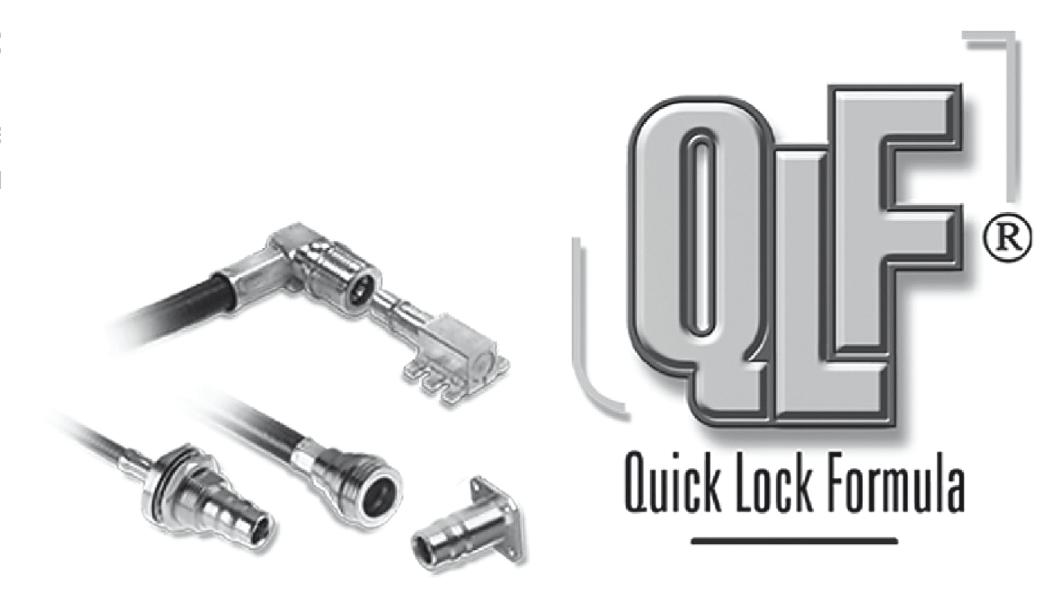
"QUICK-LOCK FORMULA™" - A COST SAVING SOLUTION
Radiall’s patented QMA and QN connectors are now the standard for the RF telecommunication industry� The "QLF” registered trademark, Quick-Lock Formula™ standard, applies to the QMA and QN series and guarantees the full intermateability between suppliers using this trademark. Using QLF™ certified connectors also guarantees the highest RF transmission performance
QMA (Quick-Lock SMA) and QN connectors (Quick-Lock N) enable fast, secured, and easy matings with minimum space requirements The QMA and QN series are the perfect alternative to SMA and N connectors in new generation telecommunication systems as well as in many other RF applications �
SECURE CONNECTION
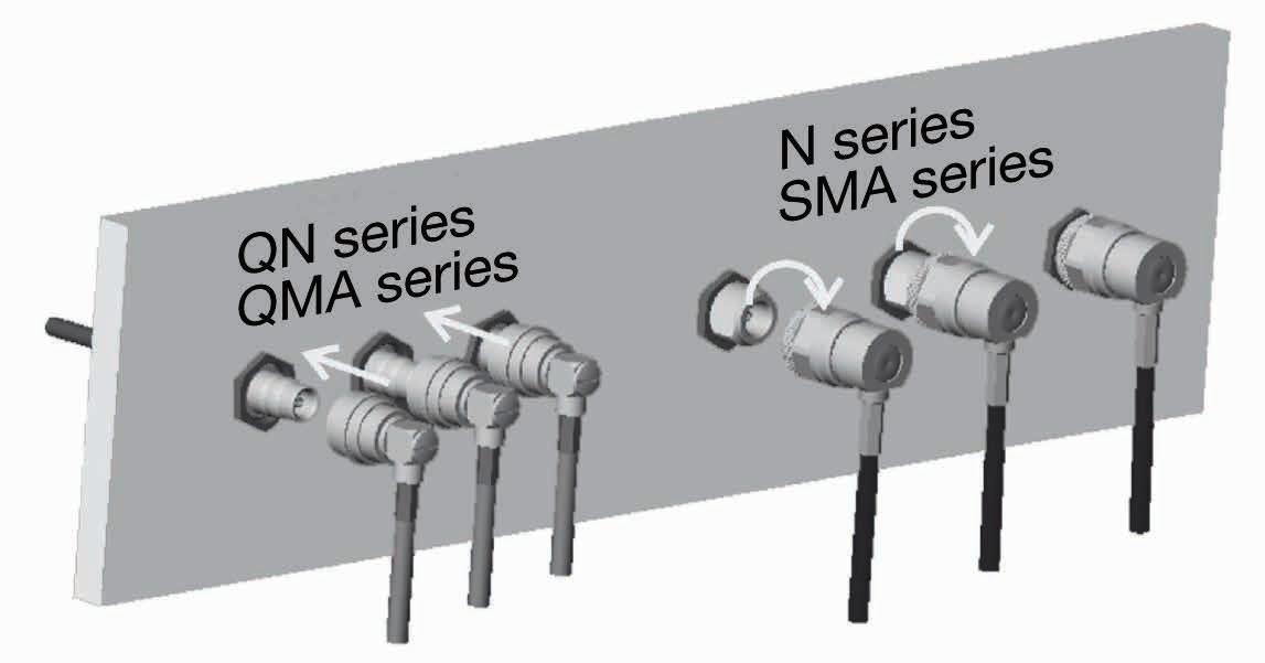
SAVES INSTALLATION TIME
QMA and QN connectors are ten times faster to connect compared to N or SMA connectors, reducing the cost of ownership� With their snap-on interface, it takes only two seconds to connect QN and SMA connectors in field conditions.
The snap-on connection is insured by a chamfer. In addition, a positive locking system ensures an excellent and secure connection. The disengagement force is lower than the panel tear-off force, preventing any panel damage. QN and QMA connectors have been successfully tested against vibration�
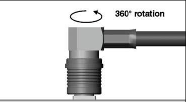
OFFERS FLEXIBILITY
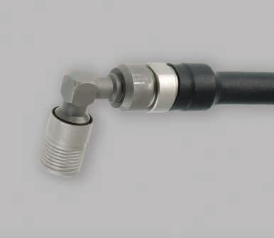
The cabled plug can freely rotate around the jack, which allows for more flexibility during the mounting process and eases the installation within the equipment �
In addition, it prevents from any added stress on the cable and return loss reduction due to cable bending� As no torque wrench is required, the risk in damaging or scratching the panel is eliminated
QMA/WQMA/QN
INTRODUCTION
SPACE SAVING
QN and QMA connectors have a lower space requirement since space for the use of a torque wrench is not necessary Therefore the distance between connectors is optimized on the panel
QMA SERIES
QUICK AND EASY DISCONNECTION
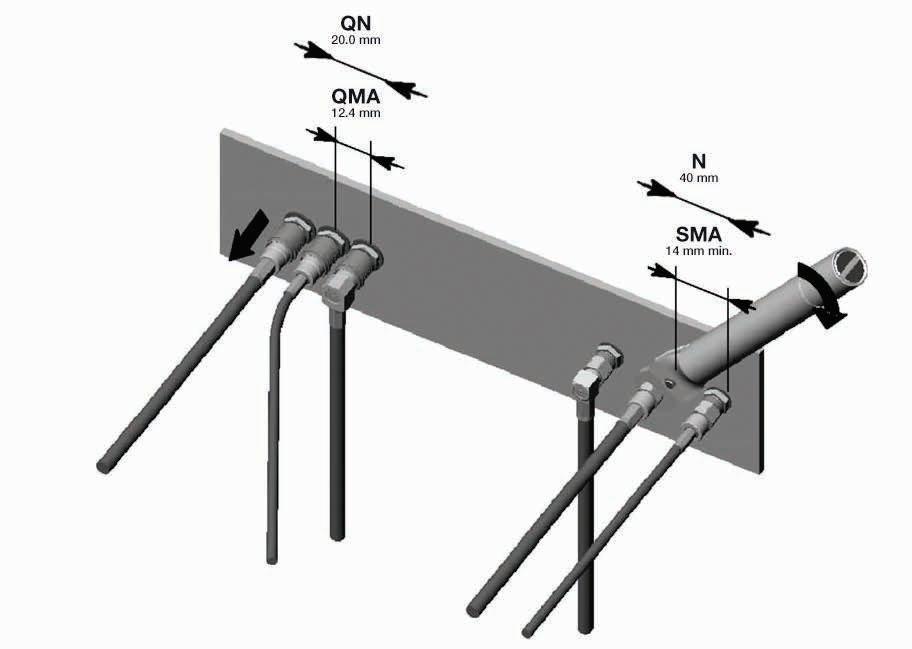
SPACE LOST DUE TO THE NORMAL USE OF THE TORQUE WRENCH
The QMA series with Quick-Lock Formula™, is the innovative patented snap-on generation of brass SMA connectors � With the same interface dimensions, QMA connectors have the identical high electrical performance as the SMA series with an easier and faster mounting design. The QMA series is a cost effective solution for the new generation of base stations The QMA series is designed for DC to 18 GHz � This series features 100 matings and total reliability as the standard commercial SMA connectors � They are fast and easy to connect and disconnect. The new QMA series offers a large range of connectors: straight and right angle plugs, bulkhead jacks, flange receptacles, PCB receptacles, adapters and more. Models are either full crimp, crimp or solder type for flexible, semi-rigid or conformable cables.
WATERPROOF QMA SERIES
Radiall expands its QMA product line with new high density RF coaxial Waterproof QMA (WQMA) connector solutions with fast and easy snap-on Quick Lock technology. WQMA connectors offer outstanding electrical performance and have environmental characteristics that provide for long lasting durability needed for the most demanding harsh outdoor applications, thus eliminating the need for costly and bulky watertight enclosures or cable entries �
Waterproof QMA CONNECTORS are fully intermateable and backward compatible with any QLF™ certified standard QMA connectors and they provide for excellent ingress protection.
• IP 68 rating when mated
• 100 matings minimum for durability
• Wide temperature range -40°C / +105°C
• Power rating 200W @ 1 GHz, 75°C
QN SERIES
Offering the same operating frequency range between DC and 11 GHz as the N series, the new QN series performance has been optimized from DC to 6 GHz for 50Ω applications. The new QN interface typically features a VSWR of 1.05 from DC to 3 GHz and 1.12 from 3 to 6 GHz. The corresponding return loss is 32 dB from DC to 3 GHz and 25 dB from 3 to 6 GHz. The high screening effectiveness enables a level of RF leakage as low as -90 dB from DC to 3 GHz and -80 dB from 3 to 6 GHz
Designed for indoor and outdoor applications such as BTS, antenna systems or test and measurement devices, QN connectors offer an outstanding intermodulation level (-155 dBC / -112 dBm) and IP rating (water and dust protection)� The power rating is 300 W at 2� 5 GHz and features 100 matings �
CHARACTERISTICS
TEST / CHARACTERISTICS
ELECTRICAL CHARACTERISTICS
VALUES / REMARKS
Impedance 50Ω
Frequency Range
Typical V.S.W.R.
DC - 6 GHz (Optimized)
DC - 18 GHz (Working Range)
• DC - 3 GHz • 3 GHz - 6 GHz 1�06 1�12
Max Insertion Loss 0.25 dB
Insulation Resistance 5000 MΩ
Voltage Rating
≤ 500 V RMS 50 Hz, Sea Level
Dielectric Withstanting Voltage 1500 V RMS 50 Hz, Sea Level
Contact Resistance
• Center Contact
• Outer Contact < 3 mΩ < 2.5 mΩ
Admissible Power @ 2.5 GHz (Continuous Power) 125 W @ T = 40°C (150 W @ T = 23°C)
Passive Intermodulation -120 dBc @ 1.8 GHz (2x20W) (static)
RF Leakage
MECHANICAL CHARACTERISTICS
Mechanical Endurance 100 Matings
Engagement and Disengagement Force
• Engagement
• Disengagement 25 N 20 N
Retention Force for Interface > 60 N
Cable Retention Force
• 2.6 / 50 S
• 2.6 / 50 D
• 5 / 50 S
• 5 / 50 D
• 5.7 / 50 D
Distance Between Connectors: c. to c.
ENVIRONMENTAL CHARACTERISTICS Temperature Range
MATERIALS
N
N
N
N
N
PLATING
Connector Dodies Brass
Male Center Contact Brass
Female Center Contact Beryllium Copper
Outer Contact Bronze
Other Metallic Parts Brass Insulators PTFE
Bodies BBR
Solder Bodies BBR
SMT Bodies NPGR
Outer Contacts BBR
Center Contacts NPGR
All dimensions are given in mm.
QMA/WQMA
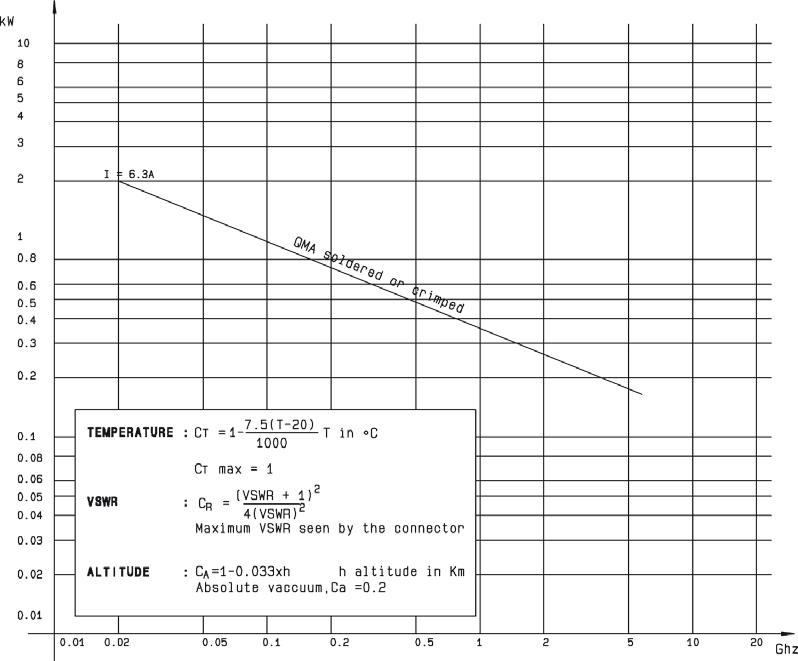
QMA CHARACTERISTICS POWER RANGE
WQMA CHARACTERISTICS
TEST / CHARACTERISTICS
ELECTRICAL AND MECHANICAL CHARACTERISTICS
VALUES / REMARKS
Impedance 50Ω Frequency DC - 6 GHz
V.S.W.R. 1.02 + 0.0200*F (GHz) Max
Center Contact Captivation Yes
Working Temperature Range - 40 °C / + 105 °C Mating Cycles 100
MATERIALS AND PLATING
Materials
Platings
Connector Body Brass BBR / NPGR / Gold over Copper
Male Center Contact Brass NPGR
Female Center Contact Beryllium Copper NPGR / Gold over Copper
Outer Contact and Other Metallic Parts Brass BBR Gasket Silicone Insulator PTFE
ENVIRONMENTAL CHARACTERISTICS
Waterproofing IP68 In Mated Condition
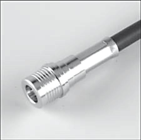
QMA PLUGS
STRAIGHT PLUGS
PLUGS
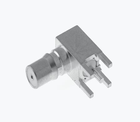
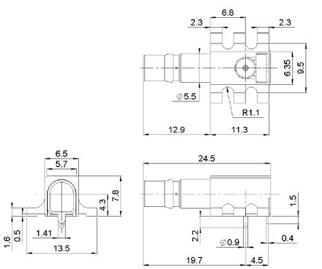
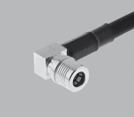
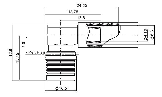
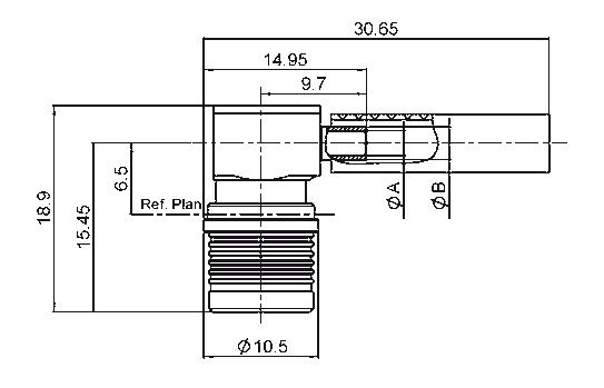
RIGHT ANGLE PLUGS
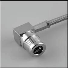
A right angle plug for 5�7 mm dia� cable is also available, please consult us
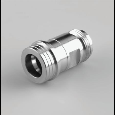
JACKS AND RECEPTACLES
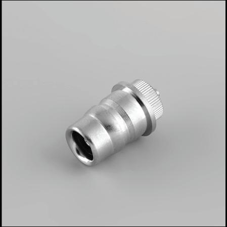
SCREW ON JACK SOLDER TYPE
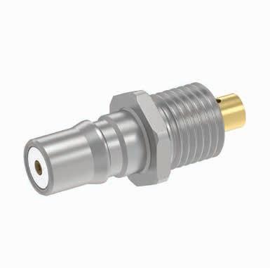
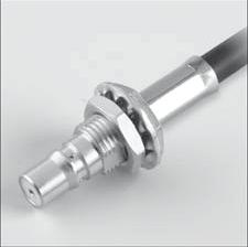
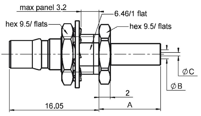
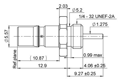
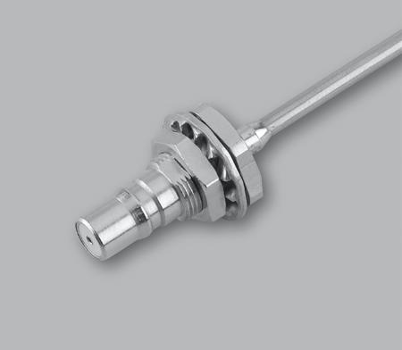
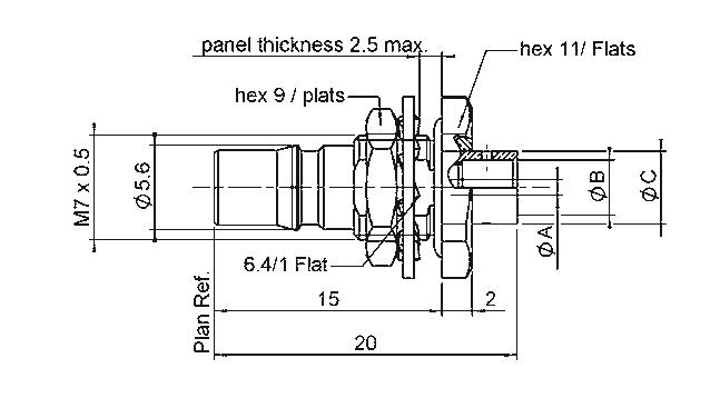
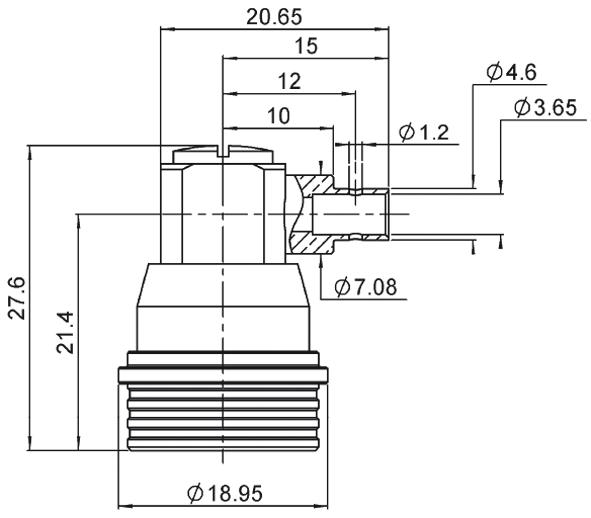
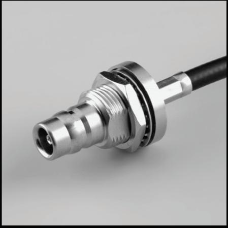
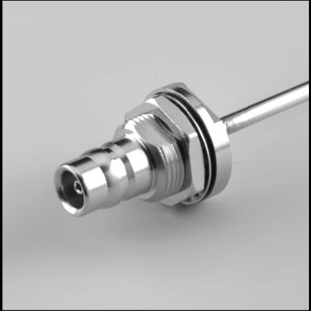
STRAIGHT BULKHEAD JACKS
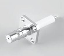
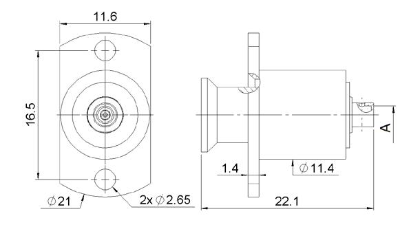
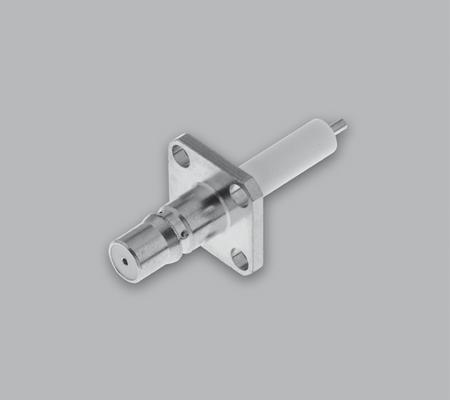
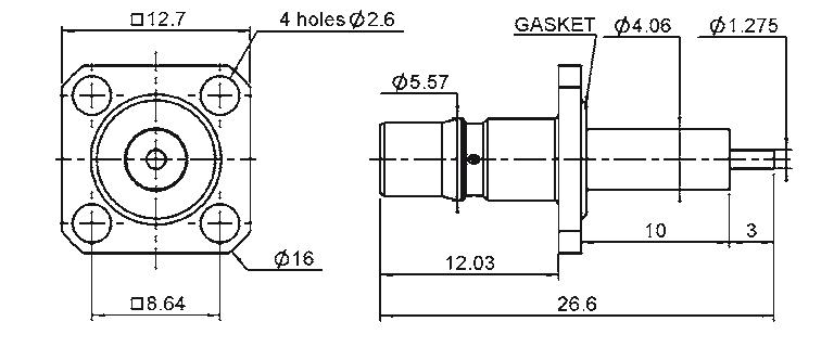
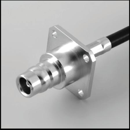
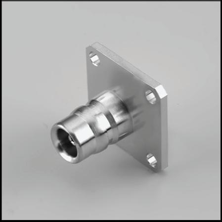
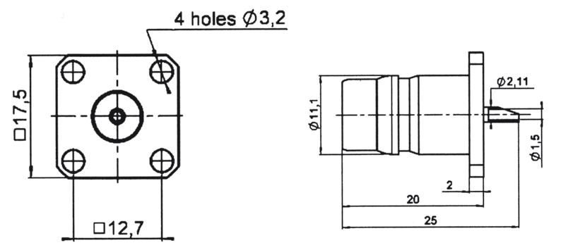
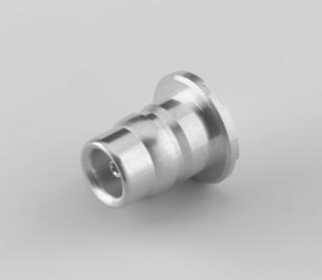
STRAIGHT FLANGE FEMALE RECEPTACLES
R123 553 000 1
R123 555 265 3
580 105 1
590 027 2
RECEPTACLES STRAIGHT
RECEPTACLES
R123 426 003 1 Yes
R123 427 803 2
PCB RECEPTACLES
R123 680 003 1 Yes
R123 682 827 2
R123 682 880
R123 444 827 3
RECEPTACLES RACK AND PANEL
ACCESSORIES AND ADAPTERS
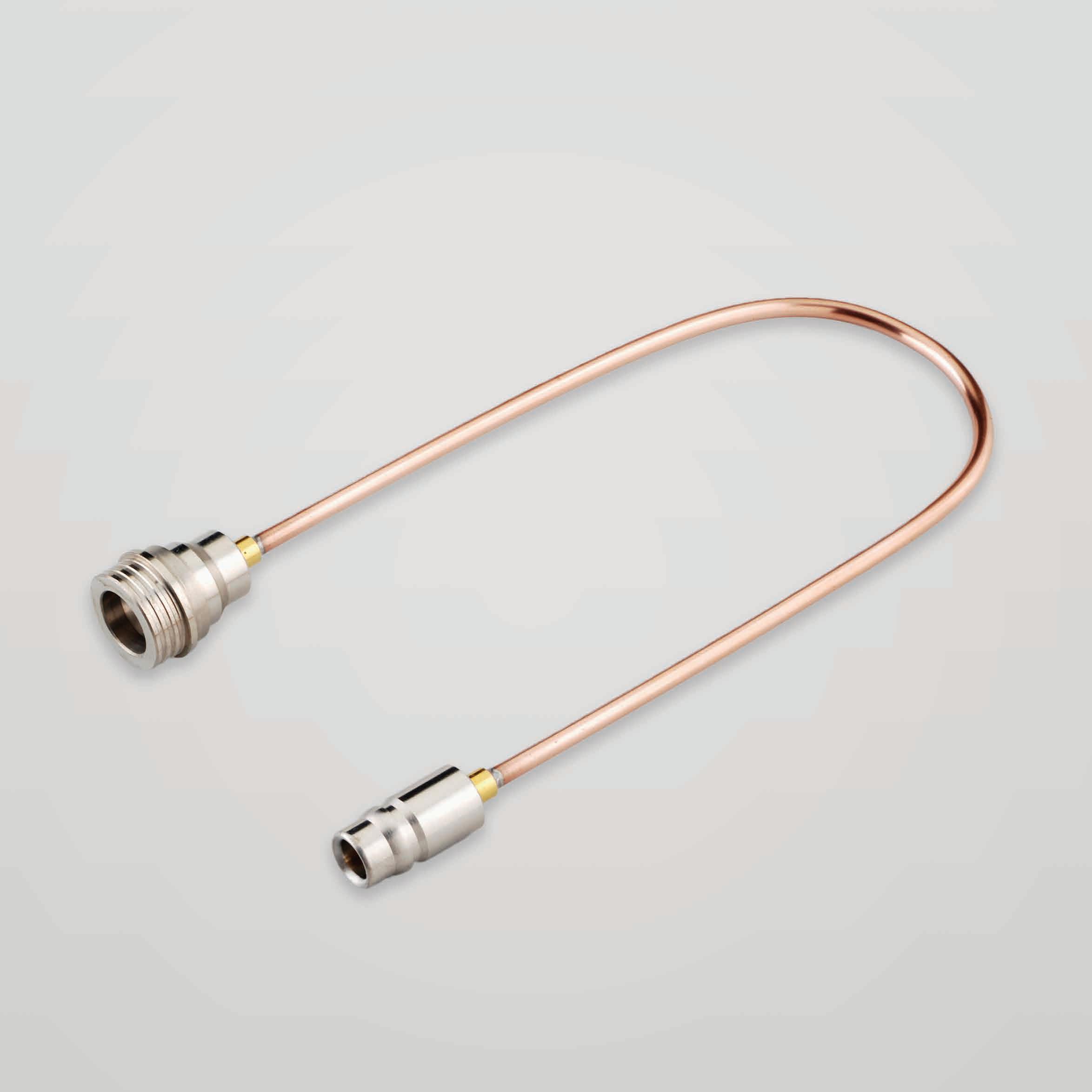
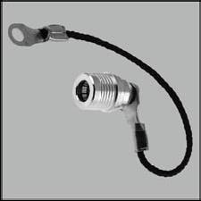
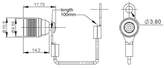
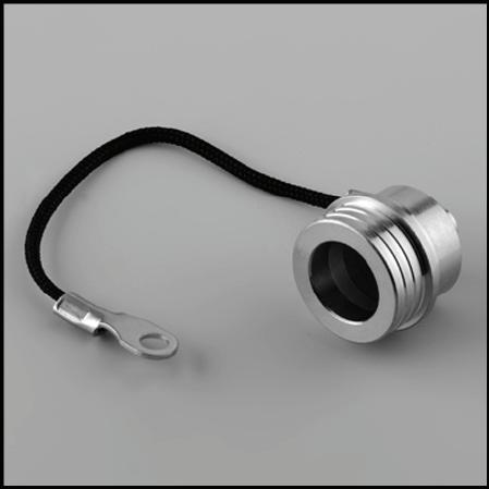
MALE CAPS WITH CORD
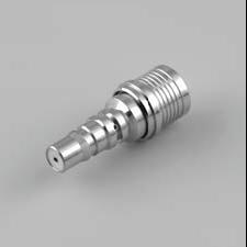
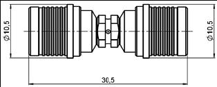
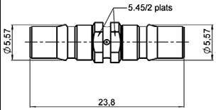
SERIES ADAPTERS
R123 703 000 1
R123 704 000 2
705 000 3
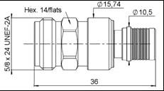
BETWEEN SERIES ADAPTERS QMA/SMA
R191 910 000 1
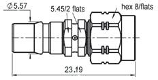
Male - SMA Male
R191 911 000 2 QMA Male - SMA Female
R191 912 000 3
QMA Female - SMA Male
R191 913 000 4 QMA Female - SMA Female
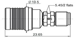
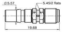
BETWEEN SERIES ADAPTERS QMA / N
R191 762 000 1
R191 763 000 2
R191 764 000 3
R191 765 000 4
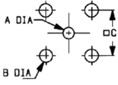
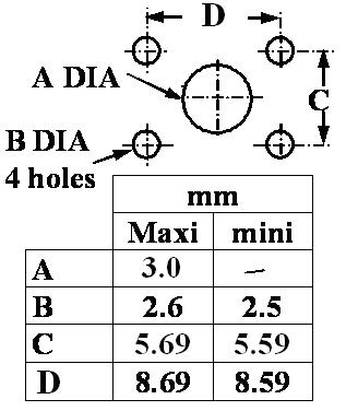
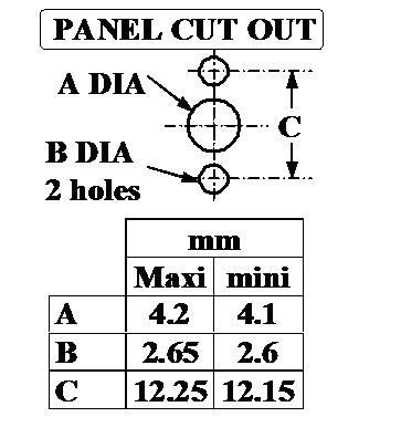
PANEL DRILLING
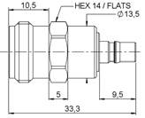
Female - N Male 1 Unit
Male - N Female
Female - N Female
Male - N Male
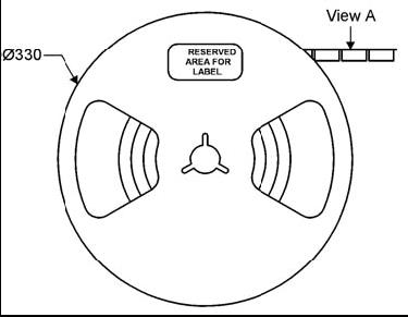
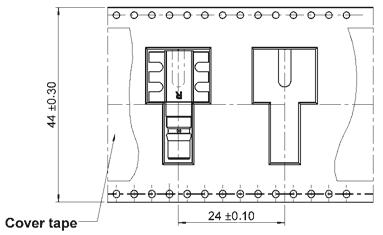
QMA RECEPTACLE PACKAGING
TAPE AND REEL
ACCORDING TO IEC
286-3 STANDARD
MATERIALS
Reel: polyester
Carrier tape: antistatic PETG (polyester)
Cover tape: polyester
RECEPTACLE
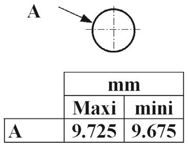
A
RECEPTACLE
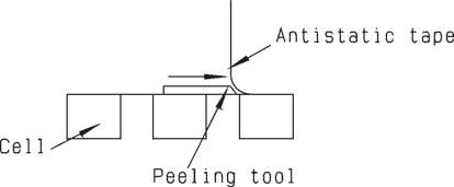
ASSEMBLY INSTRUCTIONS
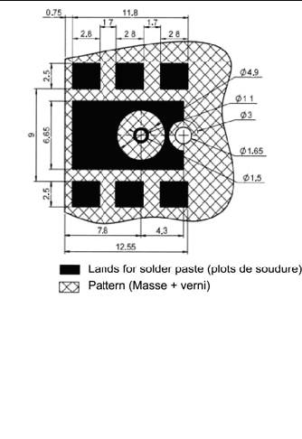
RECEPTACLE SOLDERING PATTERN
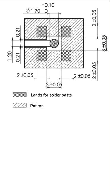
COPLANAR LINE: Pattern and signal are on the same side. Thickness of PCB = 1.6 mm. The material of PCB is the glass epoxy resin (Er = 4.8). The solder paste should be printed except for the land pattern on the PCB.

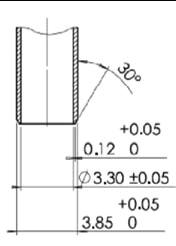
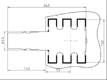
Vacuum nozzle dimensions:
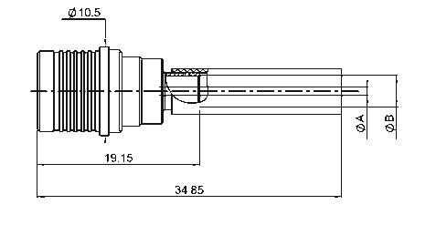
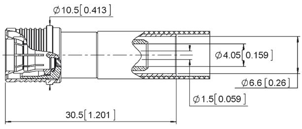
PLUGS, JACKS AND RECEPTACLES STRAIGHT PLUGS
RIGHT ANGLE PLUGS
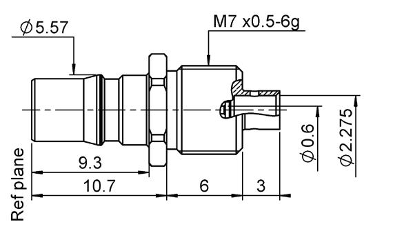
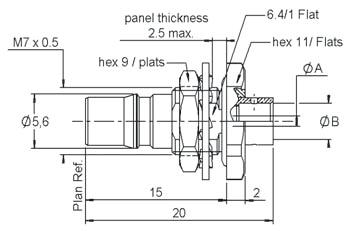
STRAIGHT BULKHEAD JACKS SOLDER
(PANEL SEAL)
RECEPTACLES (PANEL SEAL)
MALE WATERPROOF PROTECTIVE CAP
CHARACTERISTICS
TEST / CHARACTERISTICS
ELECTRICAL CHARACTERISTICS
VALUES / REMARKS
Impedance 50Ω
Frequency Range
Return Loss Typical
• DC - 3 GHz
• 3 GHz - 6 GHz
Intermodulation
RF Leakage
Dielectric Withstanting Voltage in VRMS (Interface)
DC - 6 GHz (optimized)
DC - 11 GHz (working range)
≥ 32 dB / 1.05 ≥ 25 dB / 1.12
Better - 155 dBc (2 x 43 dBm)
100 MHz to 3 GHz better than - 90 dB
3 to 6 GHz better than - 80 dB
• At Sea Level, 50 Hz 2500
Working Voltage in VRMS (Interface)
• At Sea Level, 50 Hz
Insulation Resistance
Contact Resistance
• Initial • After Test
MECHANICAL CHARACTERISTICS
Durability Matings
Force to Engage and Disengage
≤ 1000
≤ 5.10 3 MΩ
1 mΩ
1.5 mΩ
0.25 mΩ
1 mΩ
≥ 100
• Typical 40 N
Retention Force for Interface
Bending Moment Admissible Interface
Contact Captivation
• Cable Connectors
• Receptacles
ENVIRONMENTAL CHARACTERISTICS
Temperature Range
Climatic Category
≥ 450 N (101.25 Lbs)
≤ 10 Nm
≥ 28 N
≥ 18 N
- 55 °C + 125 °C
40 / 125 / 21 (IEC 60169 1 16.2)
Shock MIL STD 202F, Method 213, Condition I
Rapid Change of Temperature
Corrosion Salt Spray
IEC 60169-1 16.4 (-40 °C + 125 °C)
Test acc. to MIL STD 202F, method 101D, Condition B Vibration IEC 1169-1 Paragraph 9 3 3 (10-500 Hz; 5g)
Moisture Resistance
MIL STD 202 F, Method 106F Water Resistance IP68
MATERIALS AND PLATING
Material
Plating
Body Brass BBR over Silver
Center Contact Brass / Beryllium Copper Silver Passivated over Copper
Outer Contact Beryllium Copper BBR over Silver
Insulator PTFE
Other Parts Brass
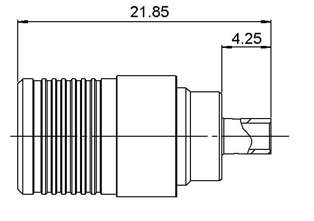
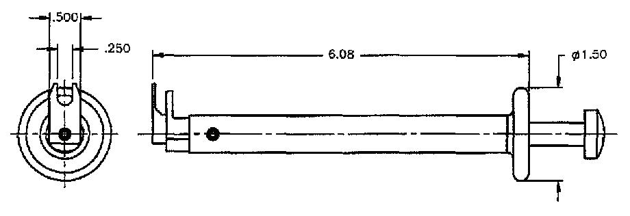
All dimensions are given in mm.
CHARACTERISTICS
POWER RANGE
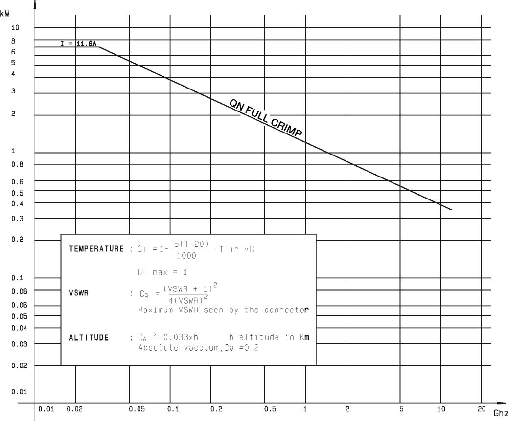
PLUGS
STRAIGHT PLUGS, FULL CRIMP TYPE, FOR FLEXIBLE CABLES
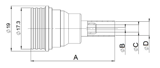
2
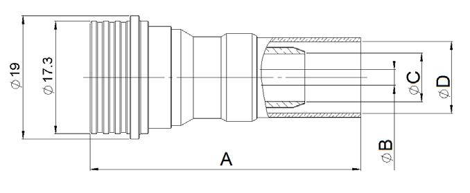
STRAIGHT PLUGS, SOLDER TYPE, FOR SEMI-RIGID CABLES
PLUGS AND JACKS RIGHT ANGLE PLUGS
STRAIGHT JACKS
JACKS AND RECEPTACLES
BULKHEAD STRAIGHT JACKS (PANEL SEAL)
FLANGE, STRAIGHT FEMALE RECEPTACLE
RECEPTACLES AND ADAPTERS WATERPROOF RECEPTACLES

R164 606 000 1
R164 606 020 2
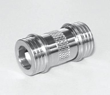
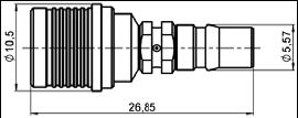
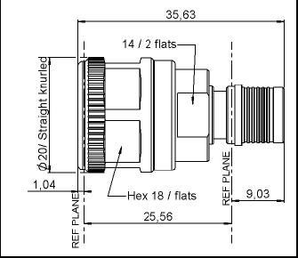
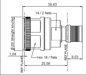
IN SERIES ADAPTERS BETWEEN SERIES ADAPTERS QN/N
705 000 1
R191 757 000 1
R191 758 000 2
R191 759 000 3
R191 760 000 4
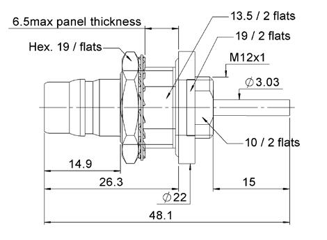
PANEL DRILLING
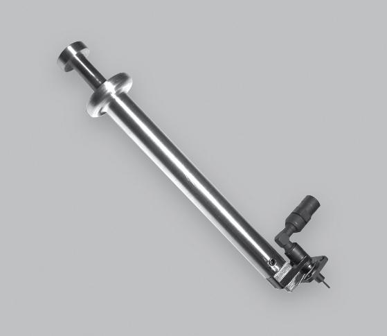
QRE™
INTRODUCTION
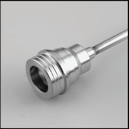
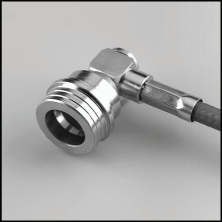
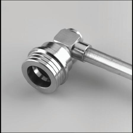
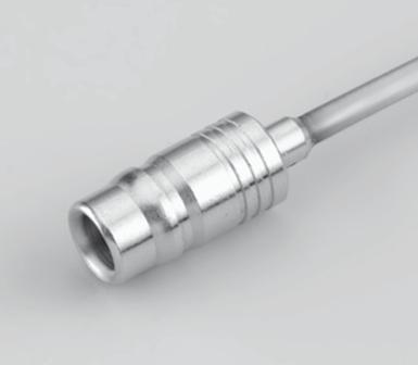
QRE™ is a Quick Lock Ruggedized connector QRE™ was developed to provide the same advantages as QMA over SMA and designed more for aerospace and defense applications �
QRE™ is made of high grade stainless steel 316L, with Teflon coated fluoro-silicone sealing o-rings which make the QRE™ interface waterproof and ultra resistant to chemical aggression and corrosion The outer slotted spring contact inspired from the QMA design was reinforced to provide reliable electrical contact during vibration and shock conditions. All QRE™ material were chosen and optimized to operate within the extended temperature range typical in Mil-Aerospace applications � Its superior latching mechanism provides the advantage of a snap-on connector while ensuring a very robust and secure connection� The retention force of the interface is 3 times higher than the QMA � With similar dimensions, QRE™ offers high density integration capabilities like QMA. In addition, a specific tool has been designed to easily disconnect QRE™ plugs on high density applications such as active array radar modules or panels
A limited range of straight and right angle connectors and receptacles is available for semi-rigid and SHF high frequency flexible cable. New connectors can be quickly developed to fit your own ruggedized coaxial cable. QRE™ cable assemblies can be delivered using our SHF airframe, lightweight or outdoor cables, with or without antiabrasion jacket. Adapters are available for test and measurement in QRE™ to SMA and QRE™ to SMA 3.5 configurations.
CHARACTERISTICS
TEST / CHARACTERISTICS
ELECTRICAL CHARACTERISTICS
Impedance
/ REMARKS
MECHANICAL CHARACTERISTICS
Durability 100 matings (500 matings option is available)
Engagement and Disengagement Forces 65 N typ Retention Force for Interface
mm (distance between center conductors) Vibration
ENVIRONMENTAL CHARACTERISTICS Temperature Range
°C/+165 °C IP rating (When Mated)
Hermeticity (When Mated)
MATERIALS AND PLATING
-6 atm cm 3 /s (CEI 68-2-17 Method Qk)
PLUGS, JACKS AND RECEPTACLE
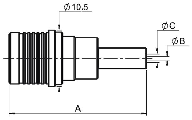
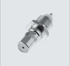
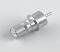
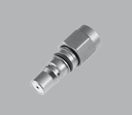
STRAIGHT AND RIGHT ANGLE PLUGS, SOLDER TYPE
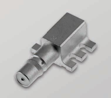
STRAIGHT FLANGE JACK SOLDER TYPE FOR SEMI-RIGID CABLE
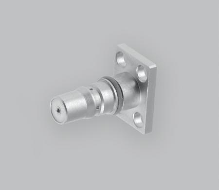
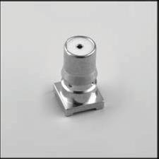
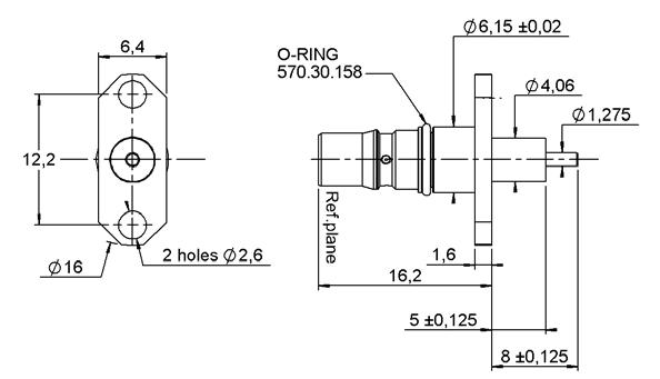
STRAIGHT FLANGE FEMALE RECEPTACLE
Notes For other semi-rigid or flexible cables, please contact us. Replacement O-rings and EMI gaskets available to order, please contact us.
QRE™
ADAPTERS AND EXTRACTION TOOL HERMETIC SCREW-IN FEMALE RECEPTACLE
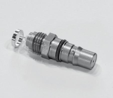
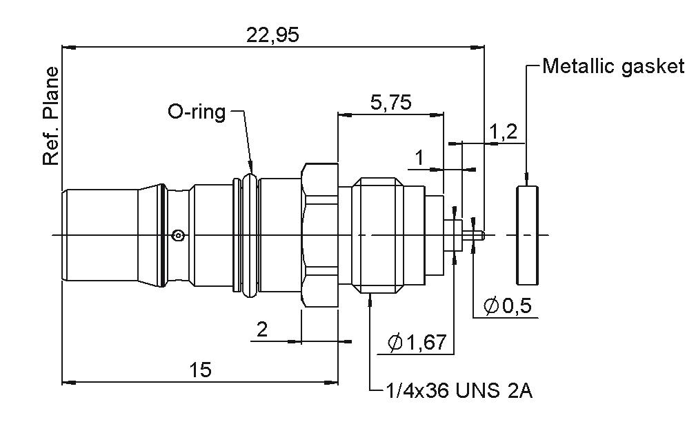
R324 555 L01 Yes P04 Passivated Metallic Gasket
STRAIGHT FLANGE FEMALE RECEPTACLE
R191 926 L01 1 Yes Passivated QRE™ Male – SMA Female
QRE™ EXTRACTION TOOL
R191 927 L01 2 QRE™ Female – SMA Male PART NUMBER TA-0457
PANEL DRILLING
Notes For QRE™ to SMA 3.5 adapters, please contact us.
This tool can be used with either straight or right angle connectors �