SIMPLIFICATION IS OUR INNOVATION Visit www.radiall.com for more information SECTION 13 4.1-9.5/4.3-10/QLI/7-16 R170/R183/R184/R185
4.1-9.5/4.3-10/QLI/7-16 | 13-3 SIMPLIFICATION IS OUR INNOVATION Visit www.radiall.com for more information 7/16 Introduction ���������������������������������������������������������������������������������������������������������������������������������������������������������������� 13-4 to 13-5 Interface 13-6 Characteristics ����������������������������������������������������������������������������������������������������������������������������������������������������������� 13-7 to 13-8 Plugs ����������������������������������������������������������������������������������������������������������������������������������������������������������������������������������������� 13-9 Jacks 13-10 to 13-11 Receptacles ���������������������������������������������������������������������������������������������������������������������������������������������������������������������������� 13-11 Adapters 13-12 Caps ���������������������������������������������������������������������������������������������������������������������������������������������������������������������������������������� 13-12 COMPOSITE 7/16 Introduction 13-4 to 13-5 Interface ����������������������������������������������������������������������������������������������������������������������������������������������������������������������������������� 13-6 Characteristics 13-8 Jacks ���������������������������������������������������������������������������������������������������������������������������������������������������������������������������������������� 13-13 Receptacles 13-13 Panel Drilling ������������������������������������������������������������������������������������������������������������������������������������������������������������������������� 13-14 QLI Introduction 13-15 Characteristics ���������������������������������������������������������������������������������������������������������������������������������������������������������������������� 13-16 Plugs 13-17 Jacks ������������������������������������������������������������������������������������������������������������������������������������������������������������������������� 13-17 to 13-18 Protective Cap 13-18 4.3-10 Introduction ��������������������������������������������������������������������������������������������������������������������������������������������������������������������������� 13-19 Characteristics 13-20 Plugs ������������������������������������������������������������������������������������������������������������������������������������������������������������������������ 13-21 to 13-22 Jacks 13-22 Panel Drilling ������������������������������������������������������������������������������������������������������������������������������������������������������������������������� 13-22 4.1-9.5 Introduction 13-23 Characteristics ���������������������������������������������������������������������������������������������������������������������������������������������������������������������� 13-24 Plugs 13-25 Jacks ���������������������������������������������������������������������������������������������������������������������������������������������������������������������������������������� 13-25
Contents
Section 13 Table of
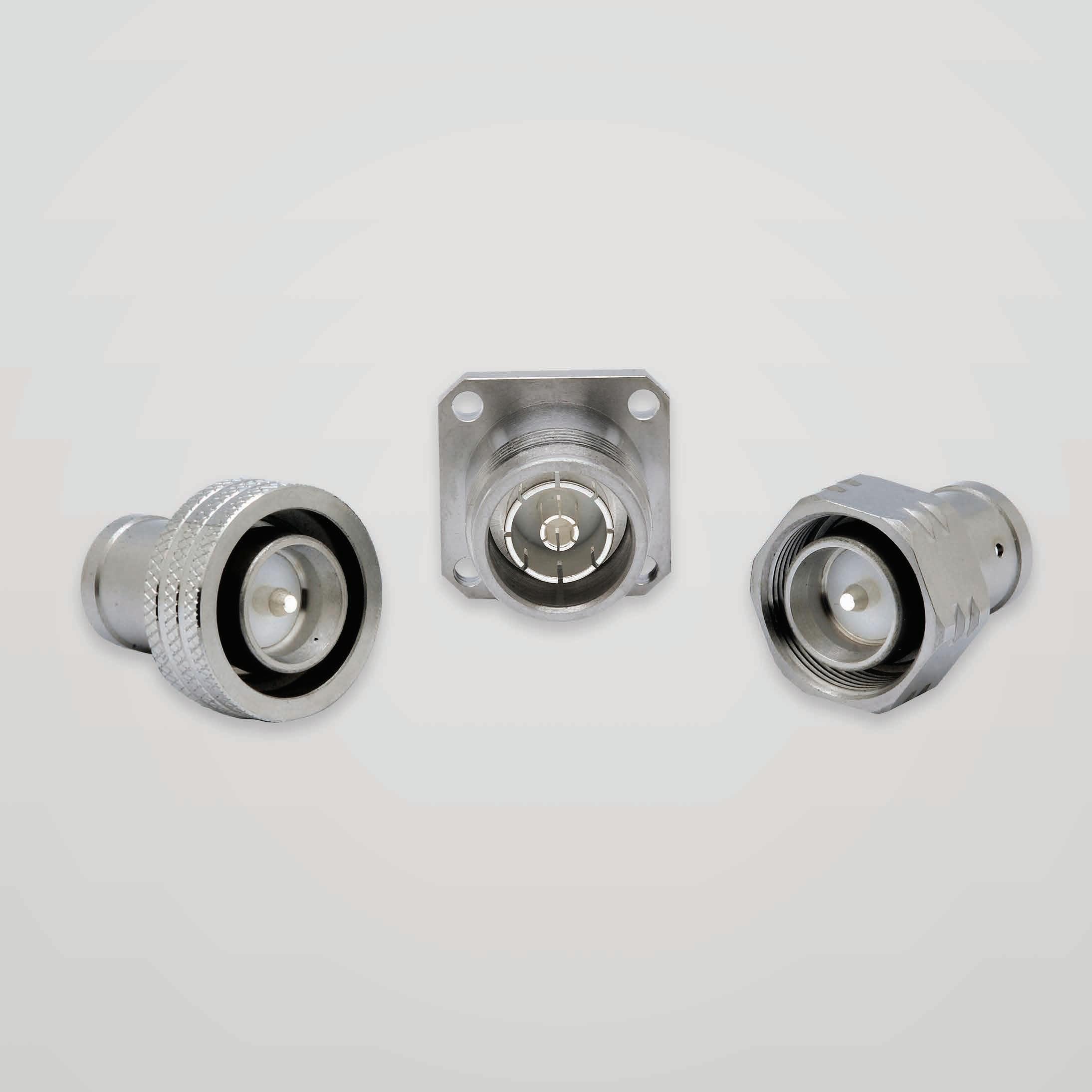
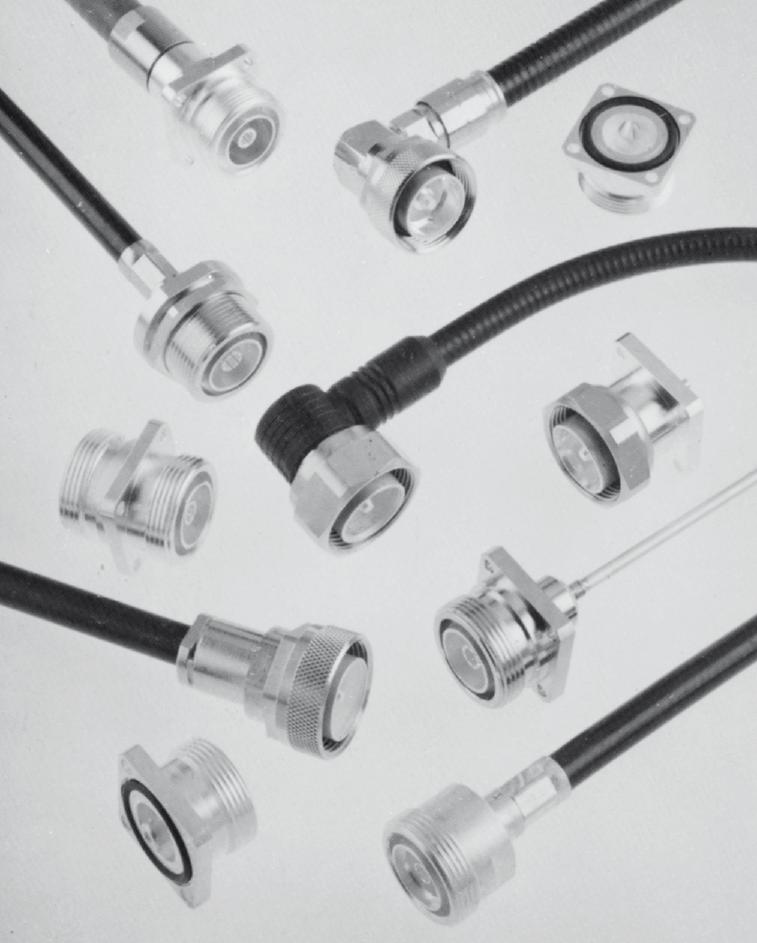
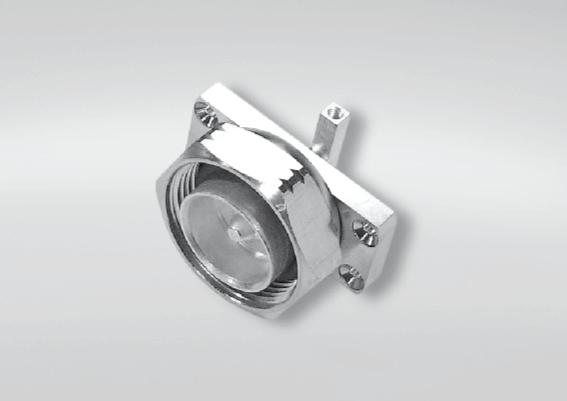
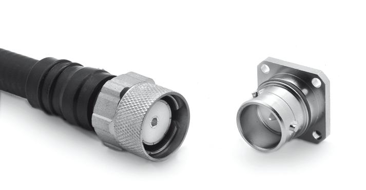
7/16/Composite 7/16 50Ω DC - 7.5 GHz
INTRODUCTION
GENERAL
• Standard coaxial connectors
• Screw-on coupling
• High power rating
• Excellent RF performance
APPLICABLE STANDARDS
• IEC 169-4
• DIN 47223
• CECC 22 190
APPLICATIONS
• Mobile communication infrastructure networks: combiner, diplexer, filter...
• Jumper and feeder cables assemblies
• Radio links
• Indoor and outdoor applications
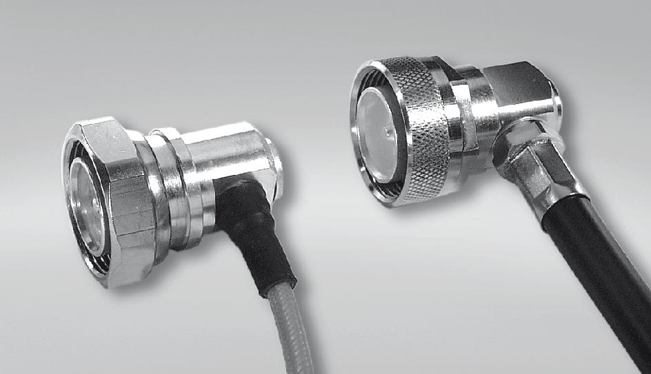
Radiall’s 7/16 series has been developed using the latest technology advances in connector design These connectors are easy to use, highly reliable, innovative and are designed to meet the needs of the telecommunications market� The complete connector series feature the following characteristics:
• An extensive range, with optimized component part design
• An upgraded cross-knurled coupling nut allowing better manual tightening
COMPOSITE 7/16
Radiall expanded its line of innovative 7/16 composite connectors with jacks and receptacles as a lightweight, low cost alternative to brass connectors� Manufactured with corrosion-proof, composite materials these new single-piece connectors are UV resistant, meeting IEC 68-2-5 and IEC-68-2-9 to withstand all environments, including harsh outdoor installations. Radiall now offers over 20 different variations. The selection of the composite materials is a result of an in-depth competitive analysis of creeping speeds of zinc and aluminum alloys. Not only do the composite materials offer considerable performance advantages guaranteeing up to 500 matings; but with more than a 50% reduction in weight, this receptacle reduces the overall weight of the final module as well as transportation costs.
13-4 | 4.1-9.5/4.3-10/QLI/7-16 SIMPLIFICATION IS OUR INNOVATION Visit www.radiall.com for more information
7/16/Composite 7/16
HIGH PERFORMANCE RANGE
• Frequency range: DC - 7�5 GHz
• 2 types of coupling nut:
• Cross-knurled and 6 flats 27 mm wide coupling nut (3 000 N.cm)
• 6 flats coupling nut (32 mm wide), allowing high coupling torque (3 500 N.cm) when used with a torque wrench
• Intermodulation performance: 2 levels
• 125 dBm cable assemblies
• 110 dBm connectors and cable assemblies
Radiall has developed its intermodulation measurement equipment following the IEC 46 D/292/NP standard proposal It is aimed at third-order IMP measurements through the reflection method. The range of this test set-up is -132 dBm (-175 dBc) under 2 x 20 W.
• High performance non-magnetic material (brass) and plating (silver) with anti-tarnishing finish (strike of BBR)
• Non-slotted outer contact on standard products
• The 7/16 connector series benefits from a complete easy-to-use range of tooling
WHAT IS INTERMODULATION?
CUSTOM MODELS
To fulfill customer requirements, Radiall offers complete design of custom connectors according to the 7/16 series standard
Intermodulation (IM) is an undesired modulation that leads to a distortion of the output high-frequency carrier. It is defined as the ratio of the 3rd order intermodulation products and the incident signal power because the most troublesome IM products are those of 3rd order�
For more detailed information, including our intermodulation measurement system and our product range, please visit www radiall com
4.1-9.5/4.3-10/QLI/7-16 | 13-5 SIMPLIFICATION IS OUR INNOVATION Visit www.radiall.com for more information
2 TYPES OF COUPLING NUT
7/16/Composite 7/16
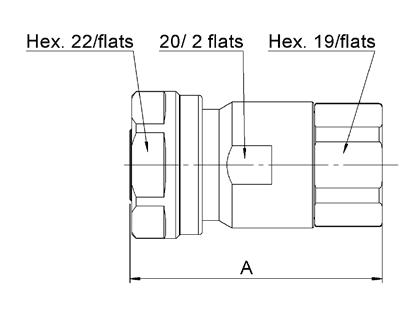
INTERFACE PLUG JACK
B DIA 22 5 22 7 885 893
DIA 6 �95 7�00 � 273 � 275
E 0 50 0 70 019 027 F 1 77 2 07 069 081
G 8 � 20 8 � 40 � 322 � 330
H 8 25 8 75 324 344
K 7 25 7 55 285 297
13-6 | 4.1-9.5/4.3-10/QLI/7-16 SIMPLIFICATION IS OUR INNOVATION Visit www.radiall.com for more information
LETTER MM INCH MIN MAX MIN MAX A DIA M29
5 M29
X 1
X 1 5
D
C DIA 17 9 17 96 704 707
LETTER MM INCH MIN MAX MIN MAX A DIA M29
5 M29 X 1 5
D DIA
7�00
273
275 E 1 47 1 77 057 069 F 7 40 7 80 291 307 G 3 �60 4 �00 �141 �157 H 7 30 7 80 287 307
X 1
B DIA 20 8 21 0 818 826 C DIA 4 97 5 03 195 198
6 �95
�
�
CHARACTERISTICS
TEST / CHARACTERISTICS
ELECTRICAL CHARACTERISTICS
Impedance
Straight Models
RG213-RG214-RG393 .141” .250”
1/2” Superflexible Corrugated
3/8” Superflexible Corrugated
1/4” Superflexible Corrugated
• Right Angle Models
RG213-RG214-RG393
1/2” Superflexible Corrugated
3/8” Superflexible Corrugated
1/4” Superflexible Corrugated
Intermodulation Product (IMP3)
• Connectors
• Home Made Cable Assemblies
Insertion Loss (dB)
Straight Connectors and Right-Angle Connectors
Leakage
Contact Resistance
• Center Contact
Working Voltage in VRMS at Sea Level
Dielectric Withstanding Voltage in VRMS • At Sea Level (at
MECHANICAL CHARACTERISTICS
Engage and Disengage
Recommended Coupling Nut Torque
• Hex. Coupling Nut
• Hex. + Cross Knurl Coupling Nut
Torque
Coupling Nut Retention Force
Cable Retention Force
Cable 5/50 & 10/50
Cable 1/4”
Cable 3/8”
Cable 1/2”
Cable 7/8”
Center Contact Retention Force
ENVIRONMENTAL CHARACTERISTICS
Temperature Range
• Flexible Cables and Corrugated Cables
• Semi-Rigid Cables
Thermo Cycling Test
Rapid Change of Temperature
High Temperature Test
Corrosion Salt Spray
Moisture Resistance
• Clamp Type
• Crimp Type
• Home Made Cable Assemblies
Hermetic Test
Leakage
REFERENCE
/ REMARKS
Heatshrink Sleeve)
4.1-9.5/4.3-10/QLI/7-16 | 13-7 SIMPLIFICATION IS OUR INNOVATION Visit www.radiall.com for more information 7/16
- 50Ω
- DC - 7 5 GHz
- 1 GHz 2 5 GHz 5 GHz 7 5 GHz •
- 1 10 max from DC to 3 GHz - 1 20 max from 3 to 7 5 GHz
Frequency Range
Typical V.S.W.R.
---1 04 1 04 1�03 1�02 1 03 1 01 1 06 1 07 1�05 1�04 1 03 1 02 1 08 1 08 1�11 1�05 1 12 1 09 1 10 1 20 1�13 1�05 1 20 1 17
- 1 15 max from DC to 3 GHz
--1 02 1 04 1 05 1 02 1 04 1 04 1 08 1 06 1 12 1 14 1 12 1 13 1 50 1 60 1 80 1 60
--110 dBm typ. (- 153 dBc typ / 20 W) -125 dBm typ. (- 168 dBc typ. / 20 W)
MIL 0.05 √F (GHz) RF
CECC 130 dB at 1 GHz Insulation Resistance CECC 10 000 MΩ min
•
CECC < 0.4 mΩ ≤ 1.5 mΩ
CECC 2 700
Outer Contact
CECC 4 000 350
70,000 feet)
Durability CECC 500 Matings Force to
CECC 15 N
-3 500 Ncm (with Torque Wrench R 282 303 500) 3 000 Ncm (with Torque Wrench R 282 303 520) Proof
CECC 3 500 Ncm
CECC 1 000 N
CECC 250 N 200 N 250 N 350 N 500 N
CECC 200 N
CECC - 55 °C + 155 °C - 55 °C + 105 °C
CECC - 55 °C / + 155 °C / 56 Days
IEC - 55 °C / + 155 °C / 5 Cycles
CECC 1000 hours / 155 °C
IEC 48 hours / Na Cl 5% / 35 °C
CECC 98 m/s 2 - 10 Hz at 500 Hz
Vibration
IEC 529 IP67 IP65
IP68
(with
(Overmolding)
IEC 5 Pa cm 3/s
CECC 1 cm 3/h max
VALUES
STANDARD
7/16
MATERIALS AND PLATING
Bodies
Center Contact • Male • Female
Gasket
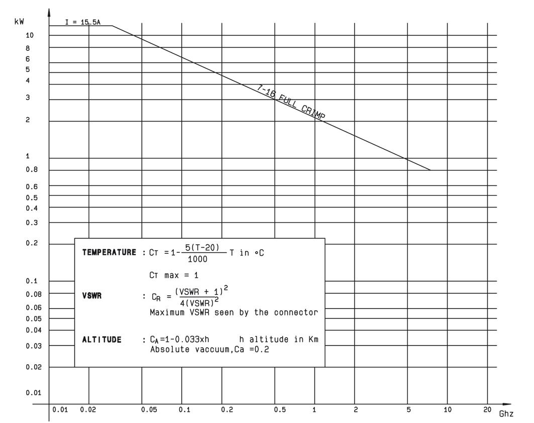
POWER RANGE
COMPOSITE 7/16 CHARACTERISTICS
TEST / CHARACTERISTICS
ELECTRICAL CHARACTERISTICS
Frequency Range
VALUES / REMARKS
DC - 7 5 GHz VSWR 1 06@DC-3 GHz - 1 10@DC - 3-7 5 GHz
High Working Voltage > 2700 V
Very Low Intermodulation
IMP3 < -125 dBm under 2 carriers of +43dBm And typically < -130 dBm
Power Handling > 800 W@ 935 MHz
MECHANICAL CHARACTERISTICS
Longlife Duration
Up to 500 Mating Cycles
Coupling Torque 35 Nm or less
Coupling Strength 1000 N
Center Contact Retention / Axial Force > 200 N
Center Contact Retention / Torque > 80 Ncm
ENVIRONMENTAL CHARACTERISTICS
Temperature Range -40 °C / +85 °C
Humidity Up to 100% @ 20 °C
Flammability Rating UL94-VO
UV Resistance IEC 68-2-5 / IEC 68-2-9
Waterproof IP67
13-8 | 4.1-9.5/4.3-10/QLI/7-16 SIMPLIFICATION IS OUR INNOVATION Visit www.radiall.com for more information
Material Plating
Brass Silver
Brass BBR
+ BBR Nut
Brass Beryllium copper Silver
PTFE -
Insulator
Silicone rubber -
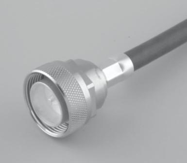
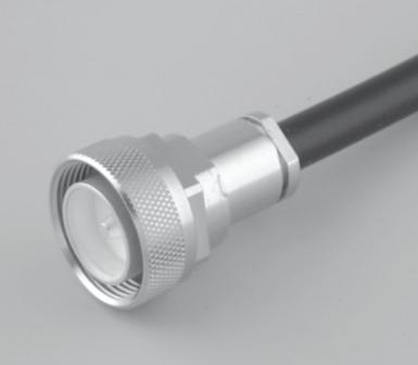
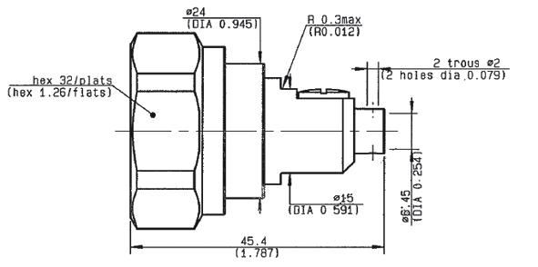
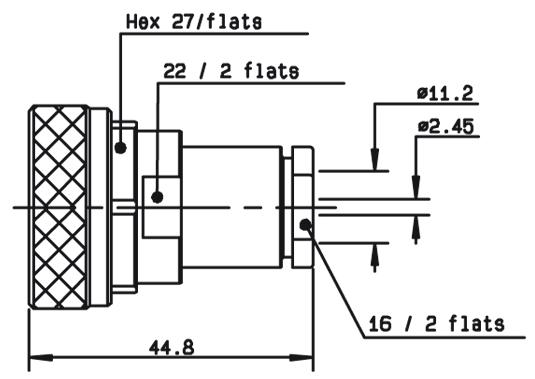
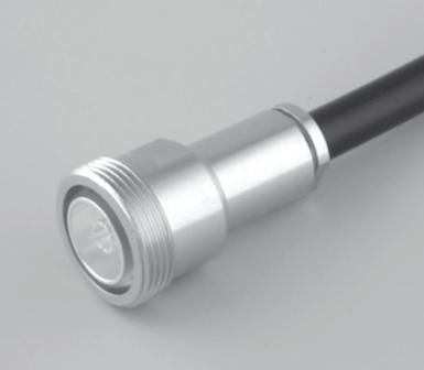
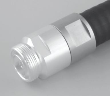
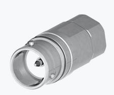
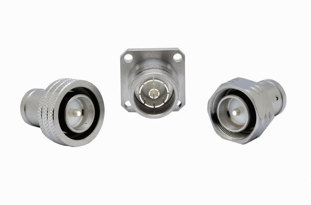
STRAIGHT PLUGS AND RIGHT ANGLE PLUGS EXTENDED DIELECTRIC FEMALE RECEPTACLE STRAIGHT PLUGS, FOR FLEXIBLE AND SEMI-RIGID CABLE
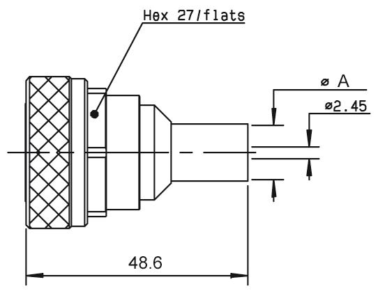
4 CABLE GROUP CABLE GROUP DIA. PART NUMBER FIG.
RG213 / RG393 10/50/S + D R185 074 000 1
RG214 11/50/D R185 077 000 11
RG213 / RG393 /RG214 10 + 11/50/S + D R185 010 000 2
RIGHT ANGLE PLUGS CRIMP AND CLAMP TYPE FOR FLEXIBLE CABLES
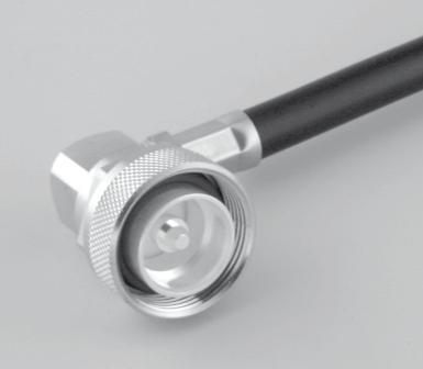
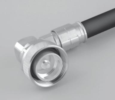
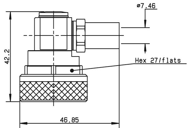
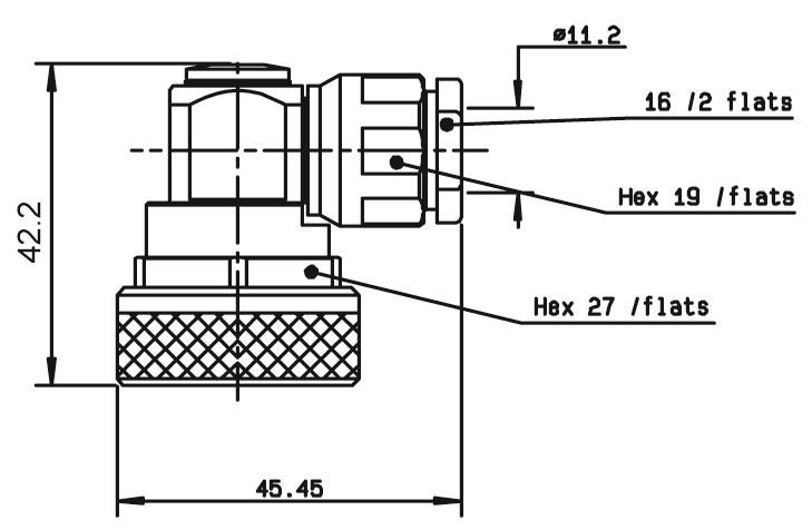
RG213 10/50/S R185 174 000 1
RG214 11/50/D R185 177 000
RG393 / RG214 10 + 11/50/D R185 160 000 2 Clamp Type
4.1-9.5/4.3-10/QLI/7-16 | 13-9 SIMPLIFICATION IS OUR INNOVATION Visit www.radiall.com for more information 7/16
FIG. 1
FIG. 3
FIG. 2
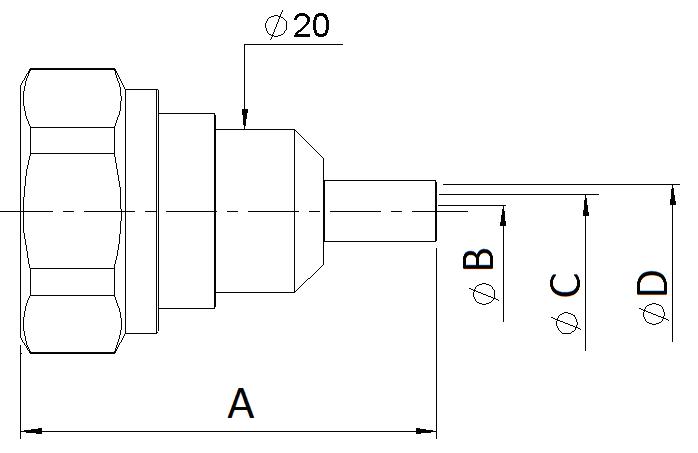
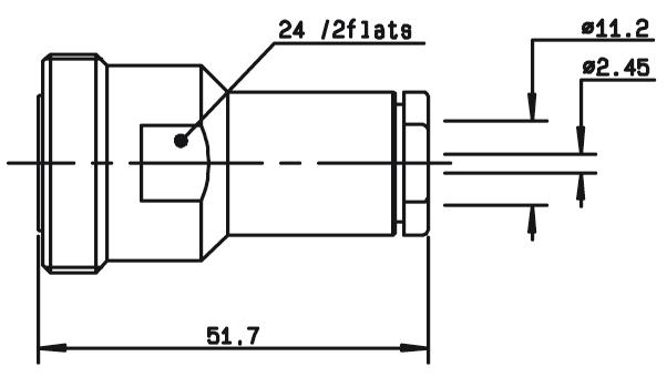
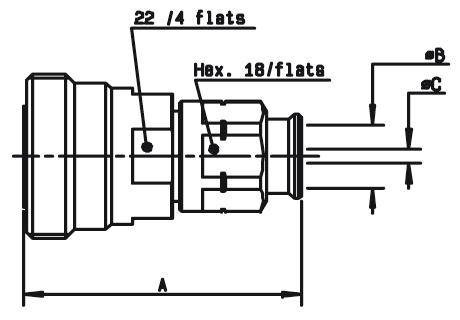
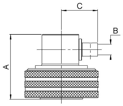
DIMENSIONS
CAPTIVE CENTER CONTACT FINISH
A B C D
FIG.
(MM)
NOTE
- -Yes Silver
11�05
+ BBR Crimp Type
- - -
4
- - - -
Clamp Type
- - - - - Silver
BBR
AEP-240FR LMR ® 240 R185 083 310 4 51 15 1 5 4 05 6 6 Yes BBR
AEP-400FR
® 400
007 49� 55 2 � 82 7� 46 11�05 AEP-600FR
600
010 58 05 4 7 11 96 15 88
RG401 250" R185 054 020 3
+
Solder Type
Clamp Type
LMR
R185 085
LMR ®
R185 077
CABLE GROUP CABLE GROUP DIA. PART NUMBER FIG. CAPTIVE CENTER CONTACT FINISH NOTE
Yes Silver
BBR
+
Crimp Type
FIG. 1
FIG. 2
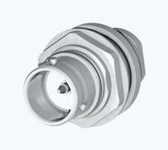
STRAIGHT JACKS AND SQUARE FLANGE JACKS
STRAIGHT JACKS
STRAIGHT SQUARE FLANGE JACKS
13-10 | 4.1-9.5/4.3-10/QLI/7-16 SIMPLIFICATION IS OUR INNOVATION Visit www.radiall.com for more information 7/16
FIG. 1
FIG. 2
CABLE GROUP CABLE GROUP DIA. PART NUMBER FIG. DIMENSIONS (MM) CAPTIVE CENTER CONTACT FINISH NOTE A B C RG393 / RG214 10 + 11/50 D R185 210 000 1 - -Yes Silver + BBR Clamp Type - 1/4” Superflexible Corrugated R185 215 200 2 49 45 7 95 4 7 - 1/2” Superflexible Corrugated R185 216 200 50 14 8 8 - 3/8” Superflexible Corrugated R185 217 200 11 7 1
FIG. 1
FIG. 2
CABLE GROUP CABLE GROUP DIA. PART NUMBER FIG. CAPTIVE CENTER CONTACT DIMENSIONS (MM) PANEL DRILLING FINISH NOTE A B C RG393 / RG214 10 + 11/50 D R185 260 000 1 Yes - - - P01 Silver + BBR Clamp Type for Flexible Cables RG402 141" R185 252 200 2 3 65 0 996 3 6 P01 Solder Type for Semi-Rigid Cables
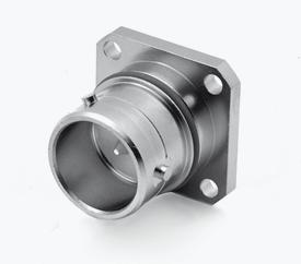
BULKHEAD JACKS AND RECEPTACLES
STRAIGHT BULKHEAD JACKS FOR FLEXIBLE CABLES AND CORRUGATED CABLES

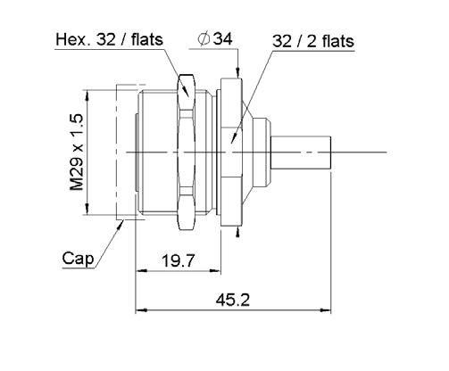
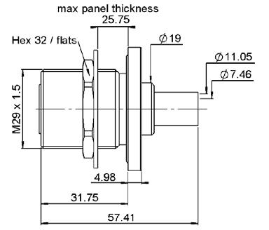
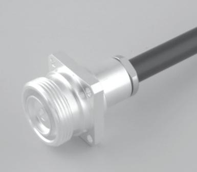
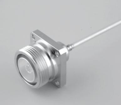
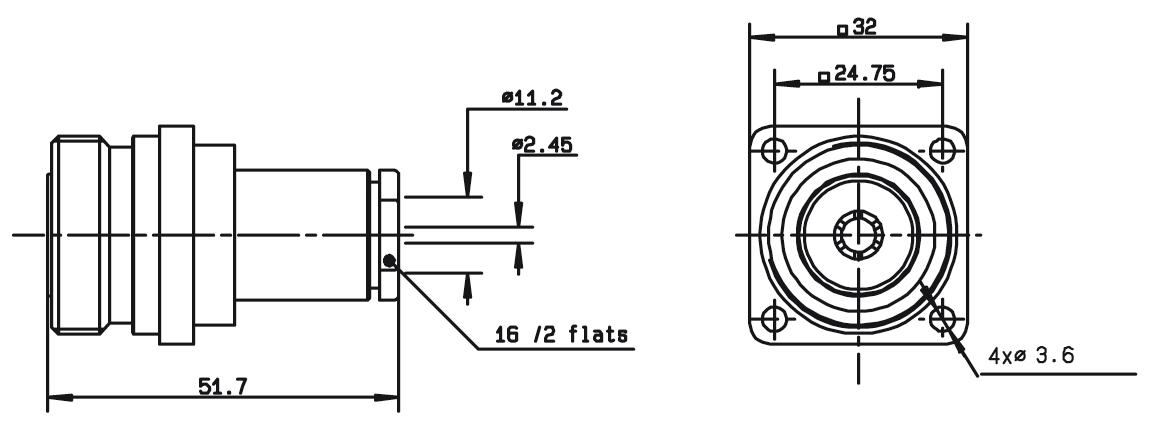
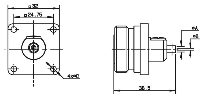
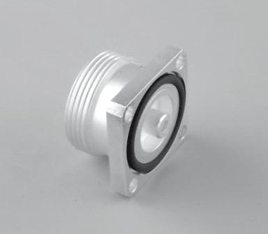
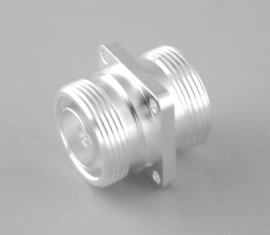
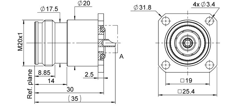
STRAIGHT FLANGE FEMALE RECEPTACLES
4.1-9.5/4.3-10/QLI/7-16 | 13-11 SIMPLIFICATION IS OUR INNOVATION Visit www.radiall.com for more information 7/16
FIG. 2
GROUP
PART NUMBER FIG.
(MM) CAPTIVE CENTER CONTACT PANEL DRILLING FINISH NOTE A B C D E AEP-240FR LMR ® 240 R185 314 100 1 19 7 45 2 1 5 4 05 6 6 Yes P02 BBR Clamp Type AEP-400FR LMR ® 400 R185 320 020 2 31 75 57 41 7 46 11 05 25 75
CABLE GROUP CABLE
DIA.
DIMENSIONS
FIG. 1
FIG. 3
FIG. 2
FIG. 4
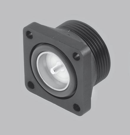
PART NUMBER FIG. CAPTIVE CENTER CONTACT PANEL DRILLING FINISH SLOTTED OUTER CONTACT PACKAGING NOTE R185 403 547 1 Yes P03 BBR No 20 With Solder Pot Contact R185 405 200 2 P05 Silver + Copper Yes - Panel Seal Flange Mount R185 406 090 3 BBR No 50 M3 R185 404 200 4 P05 Silver + Copper 20 With Slotted Contact R185 403 490 5 P04 20 With Tab Contact
FIG. 5
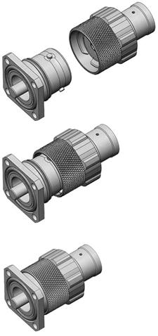
IN SERIES ADAPTERS AND CAPS IN SERIES ADAPTERS
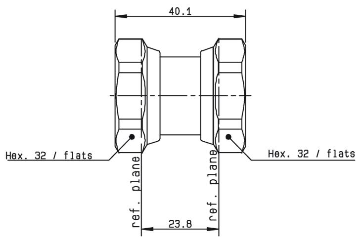
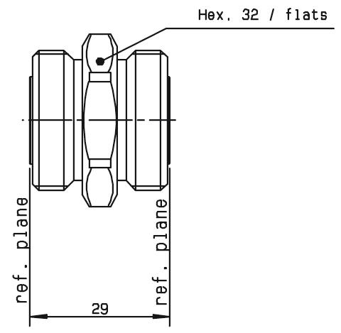
R185 703 000 1
R185 705 000 2
R185 707 000 3

-
-
- Female R185 710 000 4
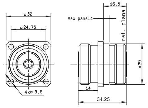
- Female Flange Mount R185 730 020 5
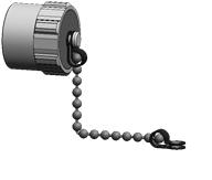
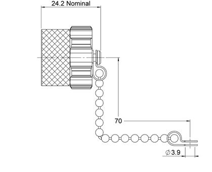
PROTECTIVE CAPS PART NUMBER
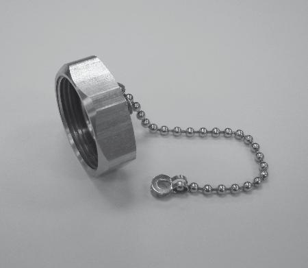
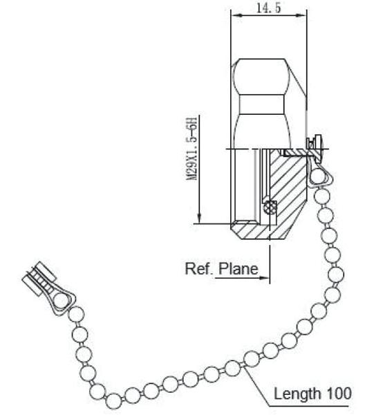
R185 812 007 Male with Chain
13-12 | 4.1-9.5/4.3-10/QLI/7-16 SIMPLIFICATION IS OUR INNOVATION Visit www.radiall.com for more information 7/16
FIG. 1
FIG. 3
FIG. 2
FIG. 3
NUMBER FIG. CAPTIVE CENTER CONTACT PANEL DRILLING FINISH NOTE
FIG. 4
PART
YesSilver
Male
- Female
- Male
P01
P06
+ Copper
Male
Female
Female
Silver + BBR Female - Female
NOTE
7/16/Composite 7/16
SQUARE FLANGE JACKS
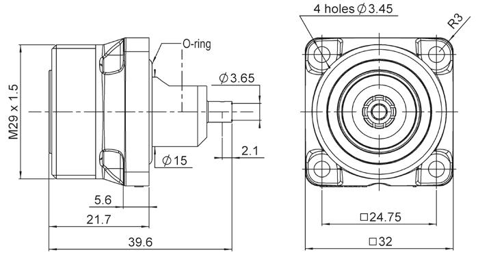
SQUARE FLANGE JACK RECEPTACLE SOLDER TYPE, PANEL SEAL
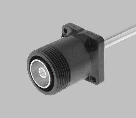
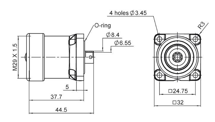
SQUARE FLANGE JACK RECEPTACLE PANEL SEAL


Notes
4.1-9.5/4.3-10/QLI/7-16 | 13-13 SIMPLIFICATION IS OUR INNOVATION Visit www.radiall.com for more information
CABLE GROUP CABLE GROUP DIA. PART NUMBER FIG. PANEL DRILLING RG402 141" R187 403 010 1 P07 RG401 250" R187 130 000 2 PART NUMBER FIG. CAPTIVE CENTER CONTACT WATERPROOF INTERFACE COLOR PANEL DRILLING R187 403 000 1 No No Black P07 R187 403 100 Yes R187 406 000 Yes No R187 406 100 Yes R187 413 000 2 No No R187 413 100 Yes R187 416 000 Yes No R187 416 100 Yes
FIG. 1
FIG. 1
FIG. 2
FIG. 2
increments of 20 units
according to customer needs
O-ring inside, only on the waterproof models [1] [1]
Available packaged in
Processed
1.
Composite 7/16
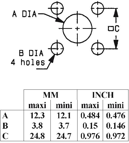
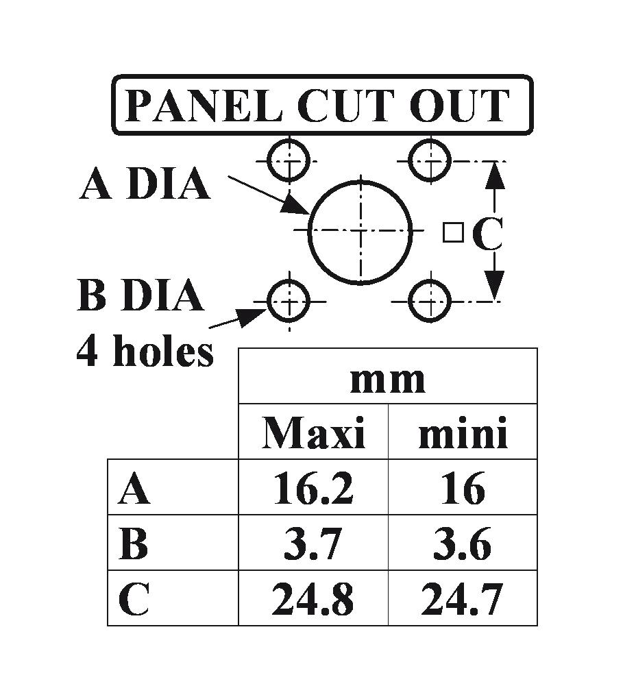
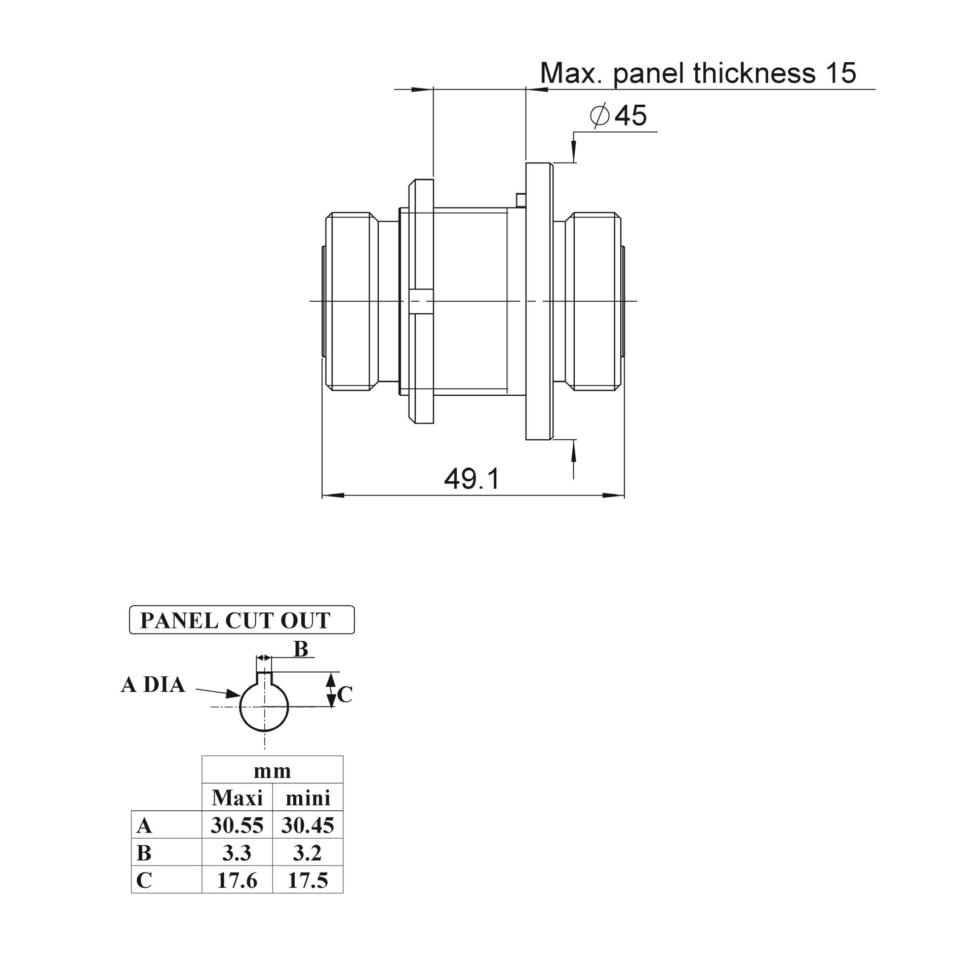
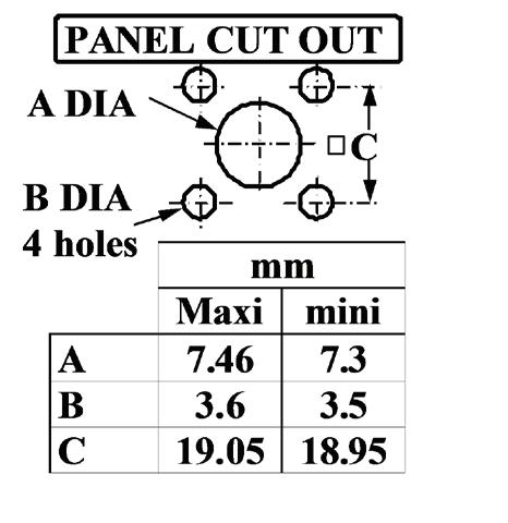
PANEL DRILLING
13-14 | 4.1-9.5/4.3-10/QLI/7-16 SIMPLIFICATION IS OUR INNOVATION Visit www.radiall.com for more information
P01 P04 P02 P05
QLI
OVERVIEW
Radiall has expanded its broad range of Quick Lock products with QLI (Quick Lock Low Intermodulation).
With the QLI, Radiall introduces a new solution for harsh environments, where performance and safety are critical QLI connectors are designed to provide performance similar to DIN 7/16 with a very low intermodulation level, and a quick and safe connection, without any tools Compared to 7/16, QLI is cheaper but also smaller (-31%) and lighter (-62%) offering an easy to use concept with its bayonet coupling system�
QLI is double sealing and offers special anti-corrosion & watertight plating, which makes it the best choice for outdoor installations and also indoor applications where the high performance is required� QLI connectors are available in plugs, jacks, straight or right angle, square sockets & bulkhead models with a compact design allowing high density integration (saving time on field installation).
Its simple jack design makes QLI robust and easy to clean when equipment is subjected to severe conditions in the field.
HIGH PERFORMANCE
• Impedance 50Ω
• Frequency range DC - 6 GHz
• Very low intermodulation level <-163dBc
• Bayonet locking concept provides coupling retention force 450 N
• VSWR 1.04 + 0.02 √f
• Meets all requirements for IP67
50Ω DC - 6 GHz
INTRODUCTION
GENERAL
• Quick Lock Low Intermodulation connector
• Bayonet coupling mechanism
• High power rating
• 31% smaller & 60% lighter than 7/16
APPLICABLE STANDARDS
• IEC 61169
• MIL PRF 39012
APPLICATIONS
• Telecom
• Medical
• Industrial
• Indoor and outdoor use
• High mating life
STEP 1: ENGAGE
STEP 2: PUSH
STEP 3: LOCK
• 3 step connection: Engage, Push & Lock
• Intuitive design concept
• Light weight
• Reduced size allows more space for other components
• RF Power: Up to 1000 W @ 2 GHz
4.1-9.5/4.3-10/QLI/7-16 | 13-15 SIMPLIFICATION IS OUR INNOVATION Visit www.radiall.com for more information
CHARACTERISTICS
TEST / CHARACTERISTICS
ELECTRICAL CHARACTERISTICS
Impedance
Frequency Range
Typical VSWR
VALUES / REMARKS
50Ω
DC - 6 GHz
1.04 + 0.02 f (GHz)
Maximum Insertion Loss 0.05 √F (GHz) dB
Insulation Resistance 5000 MΩ min
Voltage Rating <=1400 Veff
Dielectric Withstanding Voltage >2500 Veff
Contact Resistance
• Center Contact
• Outer Contact < 1 mΩ < 1.5 mΩ
Power 1000W @ 2 GHz
Intermodulation >163 dBc (>120 dBm) 2x20W
Typical RF Leakage -100 dB@1 GHz; -90 dB@3 GHz; -80 dB@5 GHz
MECHANICAL CHARACTERISTICS
Mechanical Endurance 100 Cycles
Engagement & Disengagement Force
• Engagement
• Disengagement <= 60N <= 50 N
Mating Mechanical Retention Force 450 N min
Cable Retention Force
350 N mini with 1/2" S cable Vibration IEC 611169-1 10g / 10-500 Hz
ENVIRONMENTAL CHARACTERISTICS
Temperature Range - 55 °C ~ + 120 °C
Moisture Resistance IP67
MATERIALS
PLATING
Connector Bodies Brass
Male Center Contact Bronze / Brass
Female Center Contact Bronze
Outer Contact Brass
Other Metallic Parts Brass Insulators PTFE
Bodies BBR
Outer Contact BBR
Center Contact Silver
13-16 | 4.1-9.5/4.3-10/QLI/7-16 SIMPLIFICATION IS OUR INNOVATION Visit www.radiall.com for more information QLI
PLUGS AND JACKS
STRAIGHT PLUGS
CABLE GROUP CABLE GROUP DIA. PART
/ RG141 / KX15
/
/ RG141 / RG223 / RG400
/ RG214 / RG393
RIGHT ANGLE PLUGS
STRAIGHT JACK
4.1-9.5/4.3-10/QLI/7-16 | 13-17 SIMPLIFICATION IS OUR INNOVATION Visit www.radiall.com for more information QLI
FIG. 1
FIG. 2
FIG. DIMENSIONS
CAPTIVE CENTER CONTACT FINISH PACKAGING NOTE A B C - 1/2” Superflexible Corrugated R184 061 007 1 3 8 12 55 29 Yes Silver + BBR 50 Solder - 1/4”
Corrugated R184 062 007 2 6 8 28 5 RG58
5/50/S R184 082 007 1 05 5 41 40 15 Crimp
10 3/50/S R184 086 007 2 82 11 05 39 AEP-600F
LMR ® 600 15/50/S R184 087 007 4 �7 15 � 88 42
5/50/S+D R184 006 007 2 1 05 5 6 38 5 Clamp RG213
10+11/50/S+D R184 018 007 2 45 11 2 46 5 -
R184 037 007 N/A 14 49 7
NUMBER DIMENSIONS (MM) CAPTIVE CENTER CONTACT FINISH PACKAGING NOTE A B C 1/2” Superflexible Corrugated R184 191 007 42 7 24 40 12 55 Yes Silver + BBR 50 Solder CABLE
NUMBER DIMENSIONS (MM) CAPTIVE CENTER CONTACT FINISH PACKAGING NOTE A B C 1/2” Superflexible Corrugated R184 216 007 49 1 9 00 14 00 Yes Silver + BBR 50 Clamp
NUMBER
(MM)
Superflexible
LMR ® 400
LMR400 ® FR / AEP-400FR
/
RG58
1/2” Superflexible Corrugated
CABLE GROUP DIA. PART
GROUP DIA. PART
JACKS AND CAPS BULKHEAD STRAIGHT JACK
SQUARE FLANGE STRAIGHT JACK
1
2
3
13-18 | 4.1-9.5/4.3-10/QLI/7-16 SIMPLIFICATION IS OUR INNOVATION Visit www.radiall.com for more information QLI
CABLE GROUP DIA. PART NUMBER DIMENSIONS (MM) CAPTIVE CENTER CONTACT FINISH PACKAGING NOTE A B C LMR ®240 / AEP-240FR 6 1/50/S R184 335 007 44 2 6 60 1 50 Yes Silver + BBR 50 Crimp RG213 / RG214 / RG393 10+11/50/S+D R184 339 007 43 6 11 20 2 45 Clamp
CABLE GROUP
FIG.
FIG.
CABLE GROUP CABLE GROUP DIA. PART NUMBER FIG. DIMENSIONS (MM) CAPTIVE CENTER CONTACT FINISH PACKAGING NOTE A B C D RG58 / KX15 / RG141 5/50/S R184 282 007 1 41 5 41 3 11 1 05 Yes Silver + BBR 50 Crimp RG393 / RG214 /RG213 10+11/50/S+D R184 339 007 2 43 6 11 20 2 45 - Clamp - M3 R184 405 007 3 - - - -PROTECTIVE
PART NUMBER NOTE R184 960 007 Metallic Male with Chain - IP67
FIG.
CAP
4.3-10
50Ω DC - 6 GHz
INTRODUCTION
GENERAL
• Low Intermodulation connector
• Screw-on & Push-pull coupling mechanism
• High power rating
• 30% smaller & 60% lighter than 7/16
APPLICABLE STANDARDS
• IEC 61169
• MIL PRF 39012
APPLICATIONS
• Telecom
• Medical
• Industrial
• Indoor and outdoor use
OVERVIEW
Designed for major telecom equipment manufacturers, the 4.3-10 series offers a small, lightweight solution for outdoor telecom applications where high performance is essential and low intermodulation is required
Radiall's broad product portfolio includes the 4�3-10, 4�1-9�5, 7/16 and the innovative QLI (Quick Lock Low Intermodulation) connector. These solutions are suitable for harsh environments where reliability is required.
Available in a variety of configurations including:
• Jack/Bulkhead
• Square flange receptacles and plugs
• Right angle models
• Solder, crimp and clamp models
• Screw-on and push-pull coupling mechanism
4.3-10 connectors are 30% smaller and 60% lighter than comparable 7/16 square flange jack receptacles. The new interface features a high intermodulation level ranging from 0-6 GHz and provides a low intermodulation level at <-166dBc.
Radiall's 4�3-10 connector solution is designed in accordance with international standards and manufactured to meet environmental safety requirements�
HIGH PERFORMANCE
• Impedance 50Ω
• Frequency range DC ~ 6 GHz
• Very low intermodulation level <-166dBc
• Screw-on and Push-pull coupling mechanism for safety and easy to use
• VSWR 1.04 + 0.01 √f
• Meets all requirements for IP67
• High mating life
• 3 step connection: Engage, Push & Lock
• Intuitive design concept
• Light weight
• Reduced size allows more space for other components
• RF Power: Up to 500 W @ 2 GHz
4.1-9.5/4.3-10/QLI/7-16 | 13-19 SIMPLIFICATION IS OUR INNOVATION Visit www.radiall.com for more information
4.3-10
CHARACTERISTICS
TEST / CHARACTERISTICS
ELECTRICAL CHARACTERISTICS
Impedance
VALUES / REMARKS
50Ω
Frequency Range DC - 6 GHz
Typical VSWR
1.04 + 0.01 f (GHz)
Maximum Insertion Loss 0.05 √F (GHz) dB
Insulation Resistance 5000 MΩ min
Voltage Rating <=1000 Veff
Dielectric Withstanding Voltage >2500 Veff
Contact Resistance
• Center Contact
• Outer Contact < 1 mΩ < 1.5 mΩ
Power 500W @ 2 GHz
Intermodulation <165 dBc (>120 dBm) 2x20W
Typical RF Leakage -110 dB@3 GHz; -100 dB@3~6 GHz
MECHANICAL CHARACTERISTICS
Mechanical Endurance 100 Cycles
Mating Force (Push-Pull Version)
• Engagement Force for Mating
• Separation Force for Mating
Mating Torque (Tool Screw Type)
Mating Mechanical Retention Force 450 N min
Cable Retention Force 350 N mini with 1/2" S cable Vibration
ENVIRONMENTAL CHARACTERISTICS
Temperature Range - 55 °C ~ + 90 °C
Moisture Resistance IP67
MATERIALS
Connector Bodies
Brass
Male Center Contact Bronze / Brass
Female Center Contact Bronze
Outer Contact
PLATING
Brass
Other Metallic Parts Brass Insulators PTFE
Bodies
BBR
Outer Contact BBR
Center Contact Silver
13-20 | 4.1-9.5/4.3-10/QLI/7-16 SIMPLIFICATION IS OUR INNOVATION Visit www.radiall.com for more information
<=100 N <=80 N IEC 61169-1 §9 3 6
5 N m IEC 61169-1 §9 3 6
• Torque
10g
Hz to 200
IEC 61169-1
2
Hz
§ 9 3 3
4.3-10
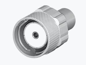
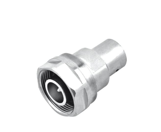
PLUGS
STRAIGHT PLUGS FOR FLEXIBLE AND SEMI-RIGID CABLES
1
/ RG393 / RG214
STRAIGHT PLUGS FOR CORRUGATED CABLES
1
1/2” Superflexible Corrugated R183 031 007
1/2” Superflexible Corrugated R183 031 017
1/4” Superflexible Corrugated R183 030 017
2
1/4” Superflexible Corrugated R183 030 007 2 Push-Pull
3/8” Superflexible Corrugated R183 032 007
RIGHT ANGLE PLUGS FOR HANDFORMABLE AND SEMI-RIGID CABLES
4.1-9.5/4.3-10/QLI/7-16 | 13-21 SIMPLIFICATION IS OUR INNOVATION Visit www.radiall.com for more information
FIG.
FIG.
FIG. 2
FIG.
FIG. 3
CABLE
GROUP DIA. PART NUMBER FIG. DIMENSIONS (MM) CAPTIVE CENTER CONTACT FINISH COUPLING MECHANISM NOTE A B C
R183 010 017 1 37 5 2 45 11 20 Yes Silver + BBR Screw-On Solder R183 010 007 2 Push-Pull RG402
KS2 141" R183 052 007 3 21 9 0 96 3 7 Clamp CABLE
GROUP
PART NUMBER DIMENSIONS (MM) CAPTIVE CENTER CONTACT FINISH COUPLING MECHANISM NOTE A B C RG402
141"
197 007 21 7 3 65 12 5 Yes Silver + BBR Push-Pull Solder
NUMBER FIG. DIMENSIONS
CAPTIVE CENTER CONTACT FINISH COUPLING MECHANISM NOTE A B C
GROUP CABLE
RG213
10+11/50/S+D
/
GROUP CABLE
DIA.
/ KS2
R183
CABLE GROUP DIA. PART
(MM)
1 27 9 3 80 12 55 Yes Silver + BBR Screw-On Solder
Push-Pull
2
1 23 8 2 6 8 Screw-On
25 9 2 8 9 45 Screw-On
1
PLUGS AND JACKS RIGHT ANGLE PLUGS FOR CORRUGATED CABLES
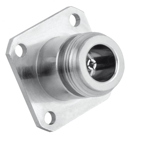
STRAIGHT SQUARE FLANGE JACKS
SQUARE FLANGE JACK RECEPTACLES
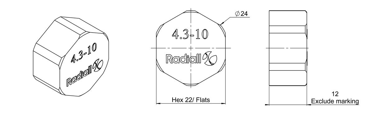
CONNECTOR CAPS
13-22 | 4.1-9.5/4.3-10/QLI/7-16 SIMPLIFICATION IS OUR INNOVATION Visit www.radiall.com for more information
4.3-10
CABLE GROUP DIA. PART NUMBER DIMENSIONS (MM) CAPTIVE CENTER CONTACT FINISH COUPLING MECHANISM NOTE A B C 1/2” Superflexible Corrugated R183 165 007 34 7 12 55 16 15 Yes Silver + BBR Screw-On Solder CABLE GROUP CABLE GROUP DIA. PART NUMBER CAPTIVE CENTER CONTACT PANEL DRILLING FINISH RG402 141" R183 252 007 Yes P01 Silver / BBR PART NUMBER CAPTIVE CENTER CONTACT PANEL DRILLING FINISH NOTE R183 252 007 Yes P01 Silver / BBR Solder Pot PART NUMBER NOTE R183 804 020 IP 67 for Mated Condition UV Resistance
P01
PANEL DRILLING
4.1-9.5
50Ω DC - 6 GHz
INTRODUCTION
GENERAL
• Screw-on coupling mechanism
• High power rating
• 20% smaller & 50% lighter than 7/16
• Low coupling torque
• Low intermodulation
APPLICABLE STANDARDS
• IEC 61169
• MIL PRF 39012
APPLICATIONS
• Telecom
• Medical
• Industrial
• Indoor and outdoor use
OVERVIEW
Radiall completes it's power connector range with 4 1-9 5, a low intermodulation series 4 1-9 5 is designed to provide similar performance to 7/16 with smaller size and weight, using a proven screw-on coupling mechanism. With its corrosion resistance, Radiall 4�1-9�5 is the ideal choice for telecom applications where severe conditions require a high performance and robust connector�
HIGH PERFORMANCE
• Impedance 50Ω
• Frequency range DC ~ 6 GHz
• Very low intermodulation level <-125dBc
• Screw-on coupling mechanism
• Coupling retention force 450 N
• VSWR 1.02 + 0.02 √f
• Meets all requirements for IP67
• High mating life
• Light weight
• Reduced size allows more space for other components
• RF Power: Up to 1000 W @ 1 GHz
4.1-9.5/4.3-10/QLI/7-16 | 13-23 SIMPLIFICATION IS OUR INNOVATION Visit www.radiall.com for more information
4.1-9.5
CHARACTERISTICS
TEST / CHARACTERISTICS
ELECTRICAL CHARACTERISTICS
VALUES / REMARKS
Impedance 50Ω
Frequency Range 0 - 6 GHz
Typical VSWR 1 02 + 0 02 F
Maximum Insertion Loss 0.05 √F (GHz)
Insulation Resistance 5000 MΩ min
Voltage Rating <=1400 Veff
Dielectric Withstanding Voltage <2500 Veff
Contact Resistance < 1.5 mΩ Power 1KW @ 1 GHz
Intermodulation -160 dBc
MECHANICAL CHARACTERISTICS
Mechanical Endurance 100 Cycles
Disengagement Force <12 N
Mating Torque 1000 N cm
ENVIRONMENTAL CHARACTERISTICS
Temperature Range - 55 °C ~ + 155 °C Sealing IP67
MATERIALS
Connector Bodies Brass
Male Center Contact Brass
Female Center Contact Beryllium Copper / Bronze
Other Metallic Parts Brass Insulators PTFE
PLATING Bodies BBR2 Outer Contact BBR2 Center Contact Silver
13-24 | 4.1-9.5/4.3-10/QLI/7-16 SIMPLIFICATION IS OUR INNOVATION Visit www.radiall.com for more information
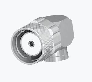
PLUGS AND JACKS STRAIGHT PLUGS
RIGHT ANGLE PLUG
SQUARE FLANGE STRAIGHT JACK
4.1-9.5/4.3-10/QLI/7-16 | 13-25 SIMPLIFICATION IS OUR INNOVATION Visit www.radiall.com for more information
4.1-9.5
FIG. 1 FIG. 2 FIG. 3
GROUP DIA. PART NUMBER FIG. DIMENSIONS (MM) CAPTIVE CENTER CONTACT FINISH PACKAGING NOTE A B C 1/2”
Corrugated R170 031 107 1 31 7 12 60Yes Silver / BBR 50 Solder Type Hand Formable Cable 141" R170 031 007 2 22 3 65 1 05 1/2”
R170 031 207 3 42 - - Clamp Type
CABLE
Superflexible
Superflexible Corrugated
GROUP CABLE GROUP DIA. PART NUMBER DIMENSIONS (MM) CAPTIVE CENTER CONTACT FINISH PACKAGING A B C RG402 Hand Formable Cable 141" R170 152 107 19 16 00 12 50 Yes Silver / BBR 50 PART NUMBER DIMENSIONS (MM) CAPTIVE CENTER CONTACT FINISH PACKAGING A B C D R170 413 127 12 8 � 50 11� 50 1� 50 Yes Silver / BBR 50
CABLE
13-26 | 4.1-9.5/4.3-10/QLI/7-16 SIMPLIFICATION IS OUR INNOVATION Visit www.radiall.com for more information Notes