OUTDOOR WIRELESS SOLUTIONS
OUTDOOR CONNECTORS
Full Line Catalog SIMPLIFICATION IS OUR INNOVATION
SIMPLIFICATION is our INNOVATION
Radiall is a community of dedicated individuals with a shared purpose: simplify life for all those who innovate. Our manufacturing expertise allows us to deliver lighter and smaller products that simplify implementation and drive performance. We recognize that simplification starts with us, but proves its true benefits when it reaches you.

TABLE OF CONTENTS Part Number Index 11 HEP2R Plating 10 7/16 Series 5 R185 Jumper Series 6 R296 OCTIS Series 9 RXF Series 8 R2F/R4F 4.1-9.5 Series 3 R170 N Series 4 R161 Adapter Series 7 R191/R192 4.3-10 Series 2 R183 NEX10™ Series 1 R180

SIMPLIFICATION IS OUR INNOVATON Visit www.radiall.com for more information NEX10 ™ SERIES R180 SECTION 1
1-3 Go online for data sheets & assembly instructions. Visit www.radiall.com and enter the part number. SIMPLIFICATION IS OUR INNOVATION NEX10™ Introduction 1-4 Characteristics 1-5 Plugs and jack ........................................................................................................... 1-6 to 1-7 Accessories and tools 1-7 Between series adapters 1-8 to 1-9 Panel drilling 1-10 SECTION 1 TABLE OF CONTENTS Contents
Introduction
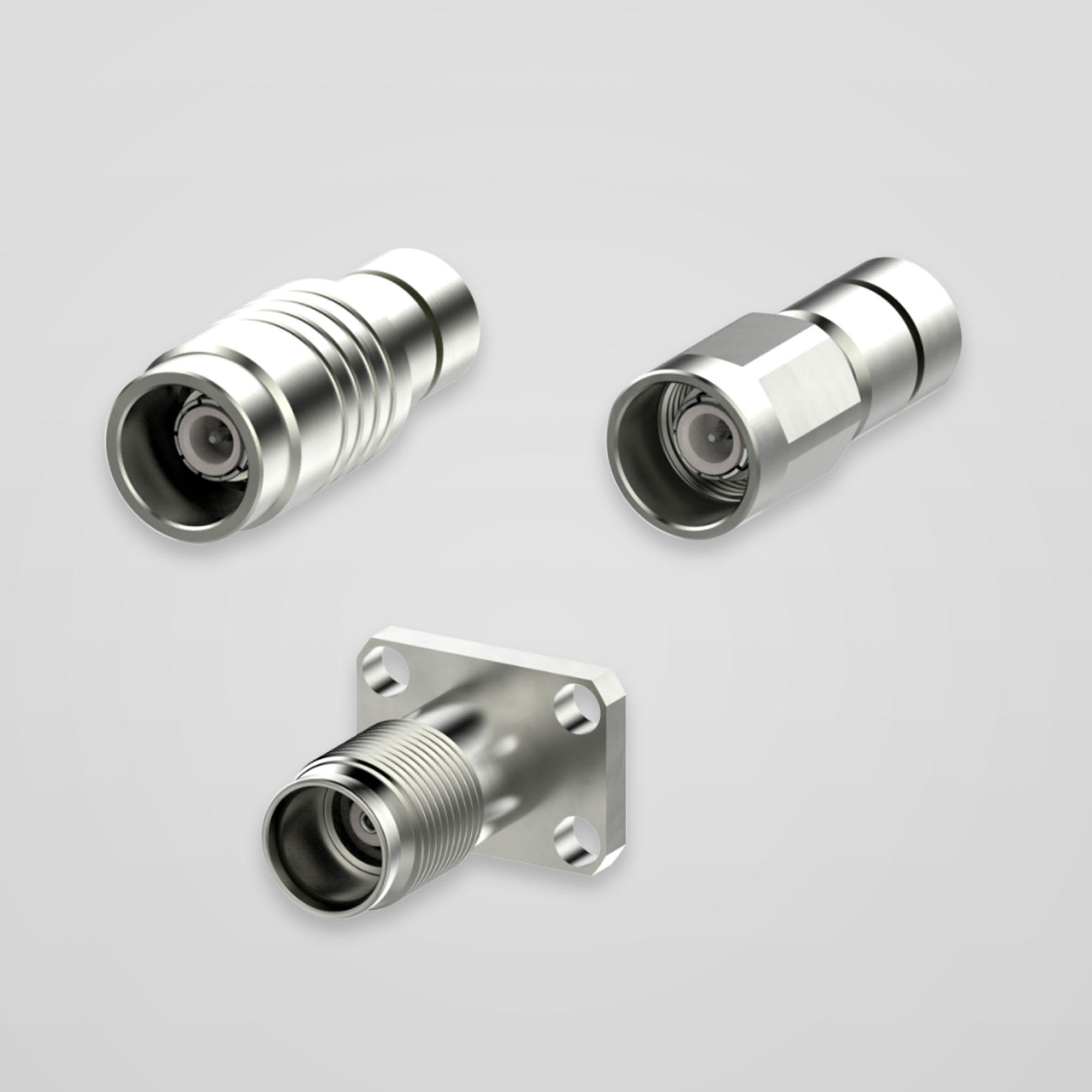
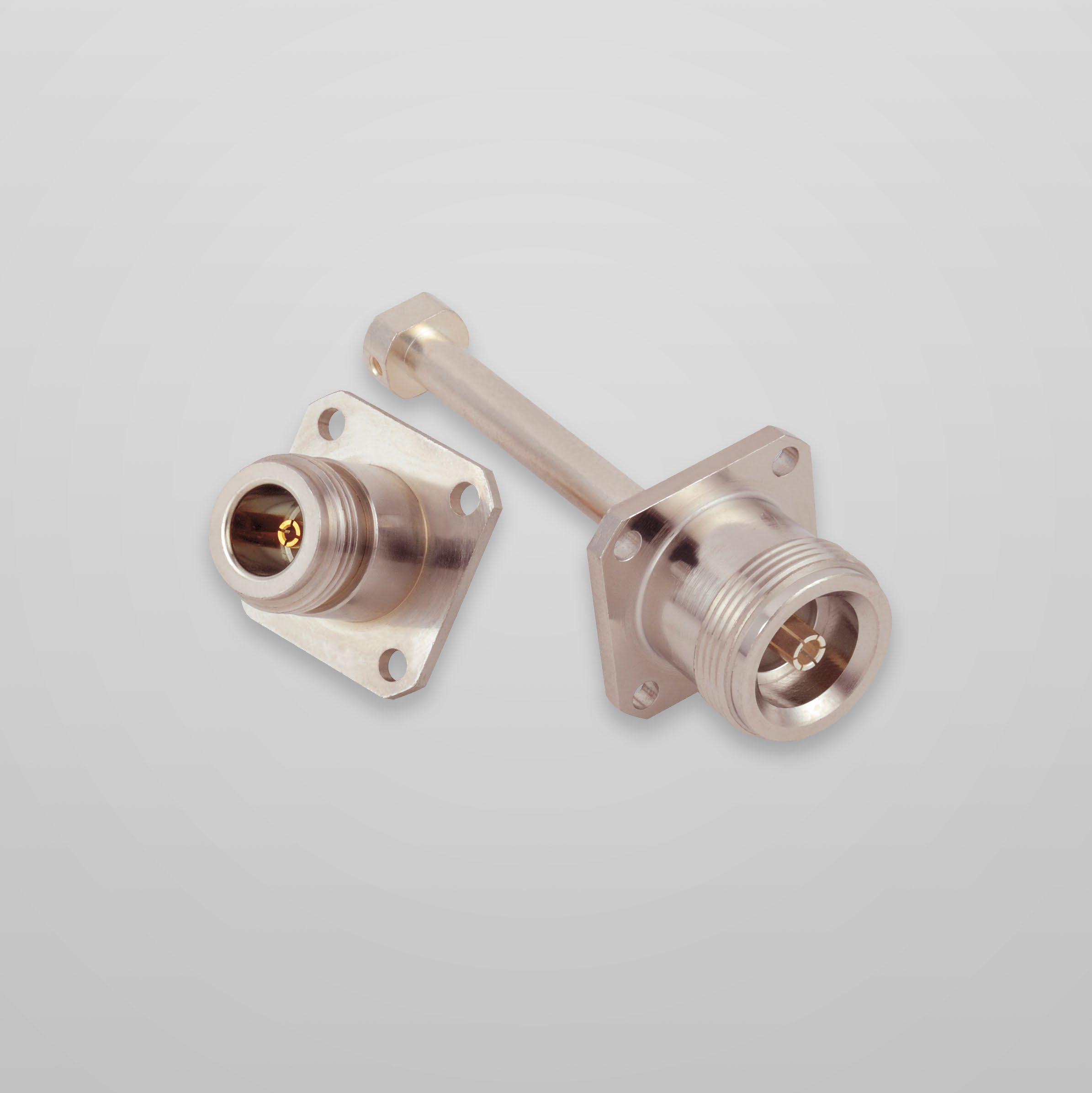
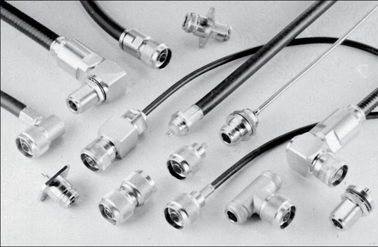
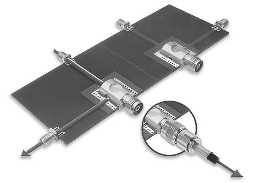
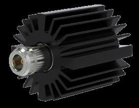
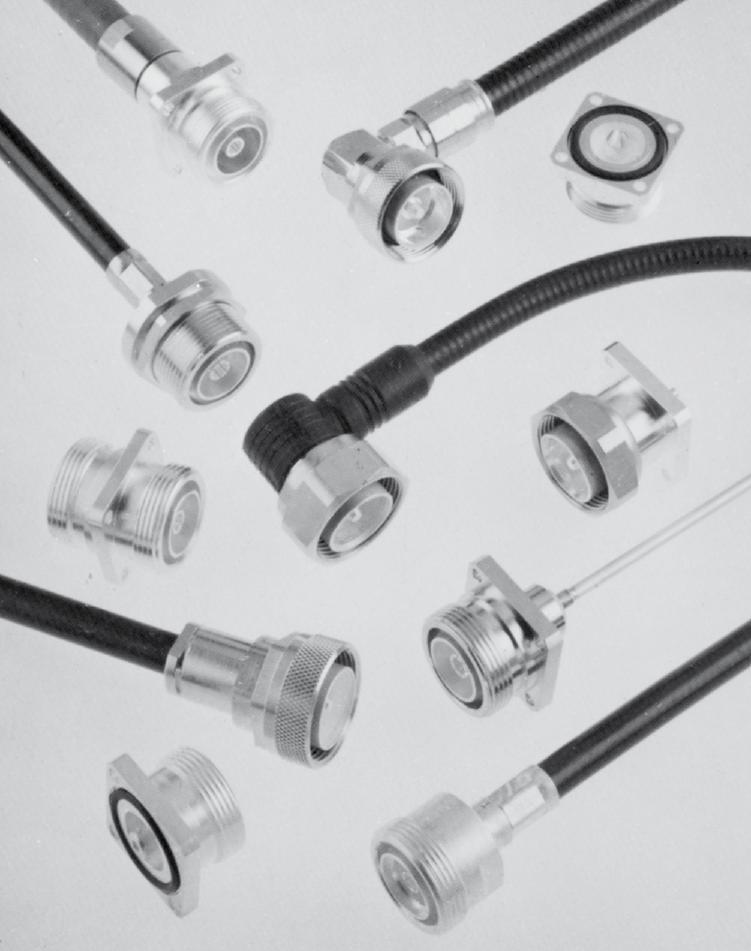
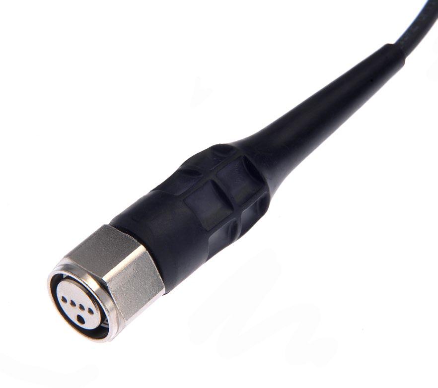
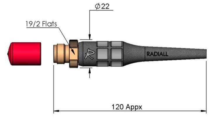
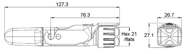
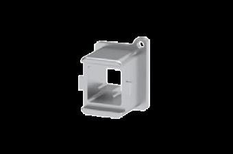
Radiall’s NEX10™ series is a miniature and lightweight RF coaxial connector with excellent intermodulation performance for outdoor telecom applications up to 20 GHz. To develop this solution, Radiall partnered with two leading RF connector manufacturers to develop NEX10™ - a new compact extremely robust Low PIM connector.
NEX10™ is the perfect solution for customers' requiring new generation equipment in the Telecom market that combines top performance with exceptional benefits and features.
To meet the performance needs of customers NEX10™ offers exceptional performance up to 20 GHz and also features a compact design which is 50% smaller than 4.3-10. This unique solution also offers separation of electrical and mechanical reference planes, which maximizes intermodulation performance under static and dynamic vibrations and torque stress conditions.
NEX10™ is available in multiple configurations:
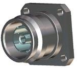
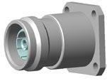
• Jack: square flange, bulkhead
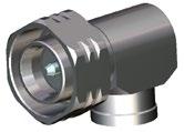
• Plug: straight & right angle
• Screw-on & push-pull coupling mechanism
FEATURES & BENEFITS
• Robust design for outdoor usage
• Low PIM, independent of applied torque
• Multiple coupling mechanism of push-pull and torque
• RF shielding
• Multi coax
• Additional boot
• Jumper
• Optimized for ¼” superflexible corrugated and smaller flexible cables
• 12.7mm minimum flange height
• Contact areas protected from damage
APPLICATIONS
• Small Cell and MIMO
• DAS/In-building
• Antennas, radios and filter output
• Outdoor and indoor
• Applications requiring PIM stability in a compact size
• Multi-coax/Blind mate applications
1-4 Go online for data sheets & assembly instructions. Visit www.radiall.com and enter the part number. SIMPLIFICATION IS OUR INNOVATION
™
NEX10
Characteristics
ELECTRICAL
CHARACTERISTICS
Values / Remarks
Impedance 50Ω
Frequency DC - 20 GHz
PIM (passive intermodulation) -166 dBc, 2x43 & 2x40 dBm (static and dynamic)
Power 100W @ 2GHz @ 85°C
Return loss (typical)
Screening effectiveness
• DC to 6 GHz (torque type)
• DC to 3 GHz (push-pull)
• 3 to 6 GHz (push-pull)
Lightning protection
Contact resistance
Voltage Operating voltage: 1kV Breakdown voltage: 3kV
MECHANICAL CHARACTERISTICS
Coupling mechanisms
Durability (mating cycles)
Boot protection
Mating characteristics
• Quick-lock
- Engagement force
- Disengagement force
• Screw
- Recommended torque
Interface retention force
Cable size diameter
Torque, Push-Pull
100 min.
500 for test and measurement types
Designated area for sealing
50 N typical 35 N typical
1.5Nm (Maximum 5Nm)
Quick-lock: 150 N min.
Screw: 500 N min.
Optimized for cables upto 1/4"
Bending force 5Nm
ENVIRONMENTAL CHARACTERISTICS
Temperature range -55°C/+125°C
Corrosion 48 hours salt mist test
Interface ingress protection
IP68 (24hrs, 1m, room temp, mated pair)
RoHS Compliant
NEX10 ™
1-5 Go online for data sheets & assembly instructions. Visit www.radiall.com and enter the part number. SIMPLIFICATION IS OUR INNOVATION
50W
250W @2GHz @25°C
@ 2GHz @ 105°C
DC-4 GHz 4-6 GHz 6-10 GHz 10-20 GHz › 36 dB › 34 dB › 30 dB › 20 dB
-
110 dB tyical - 90 dB tyical - 70 dB tyical
±1 kA 10/350 µs pulse and ±4 kA 8/20 µs pulse ±1 kA 10/350 µs pulse and ±4 kA 8/20 µs pulse
• Center conductor • Outer conductor
Center contact
mΩ Outer
2.0
contact 1.0 mΩ
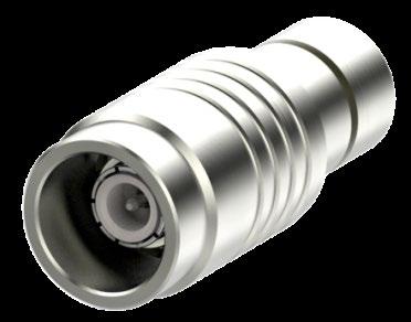
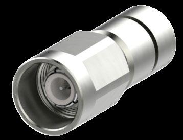
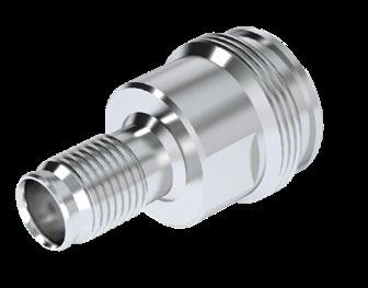
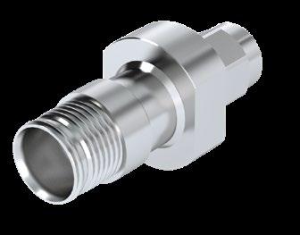
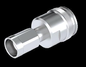
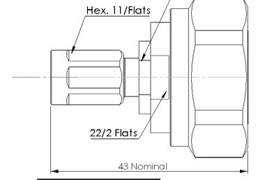
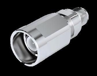
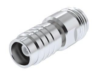
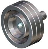
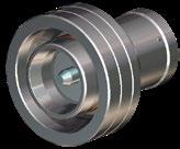
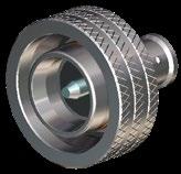
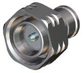
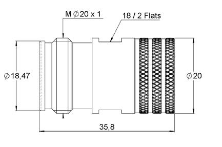
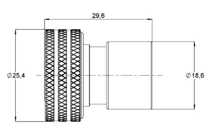
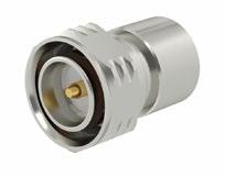
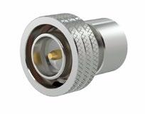
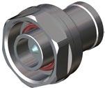
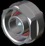
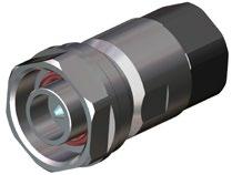
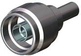
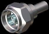
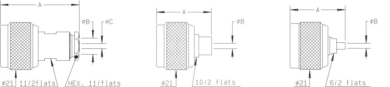
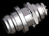
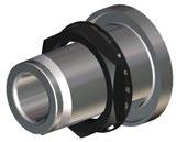
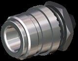
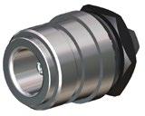
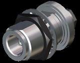
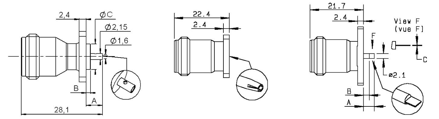
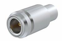
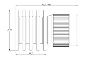
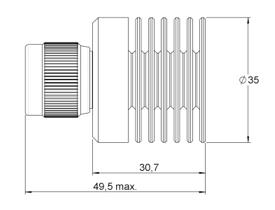
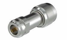
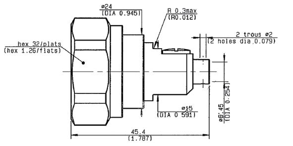
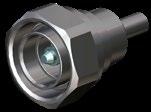
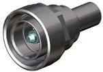
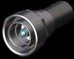
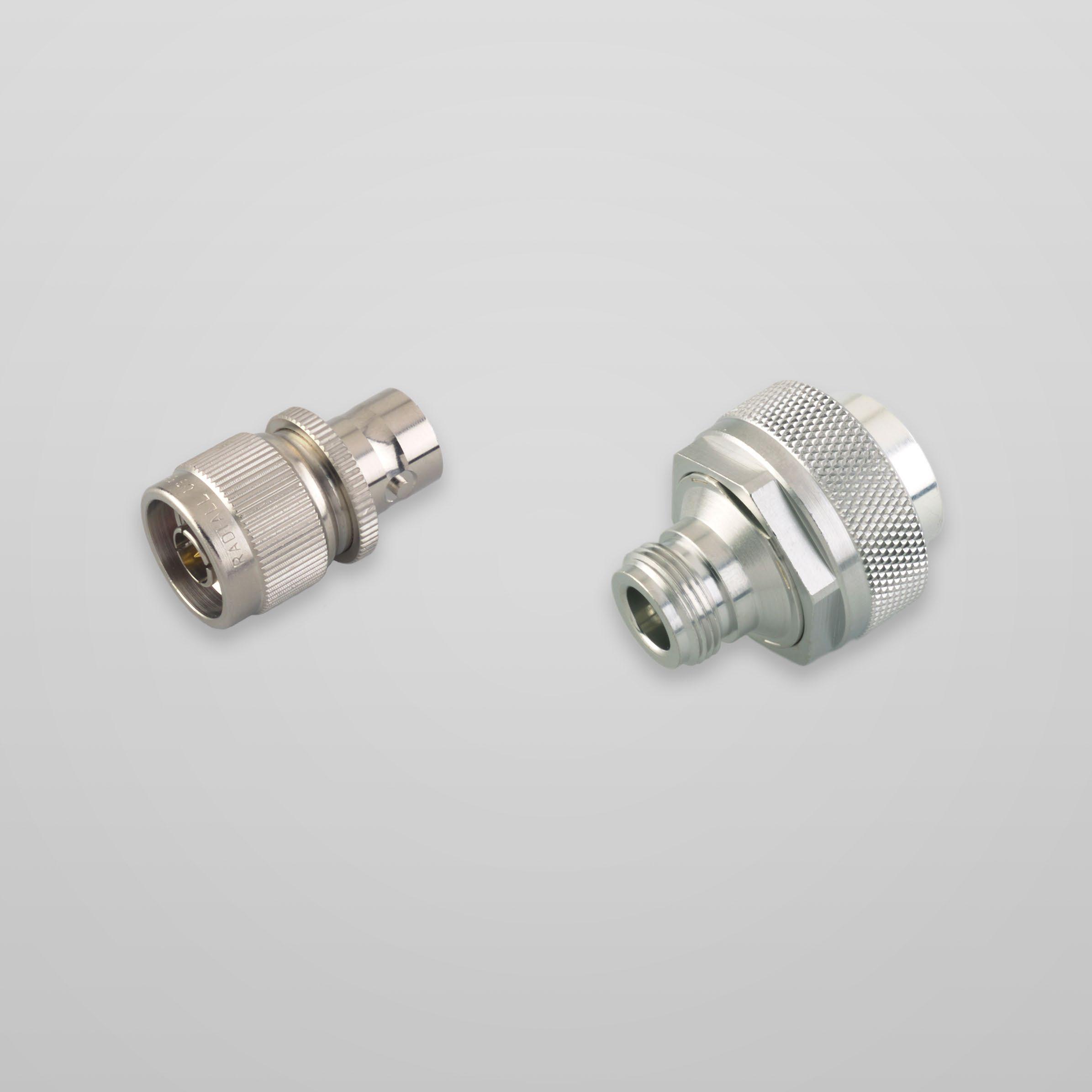
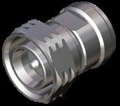
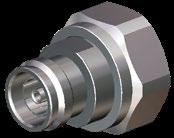
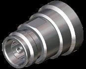
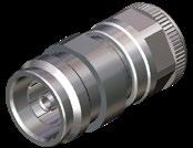
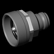
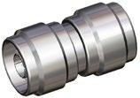
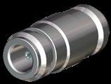
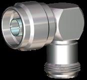
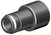
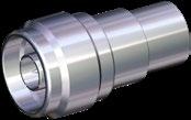
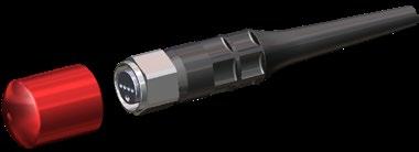
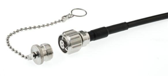
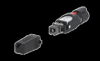
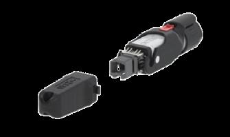
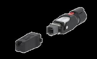
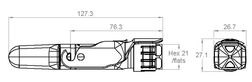
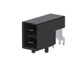
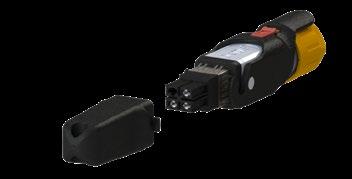
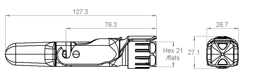
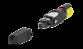
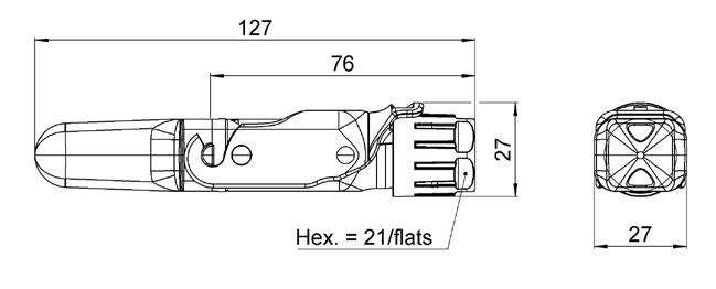
Plugs and Jacks
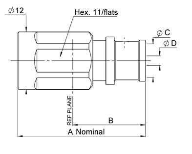
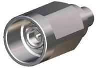
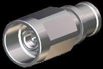
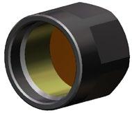
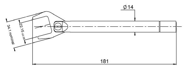
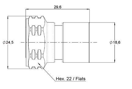
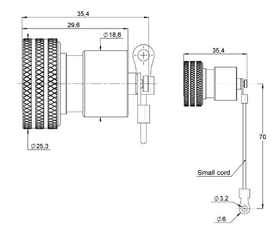
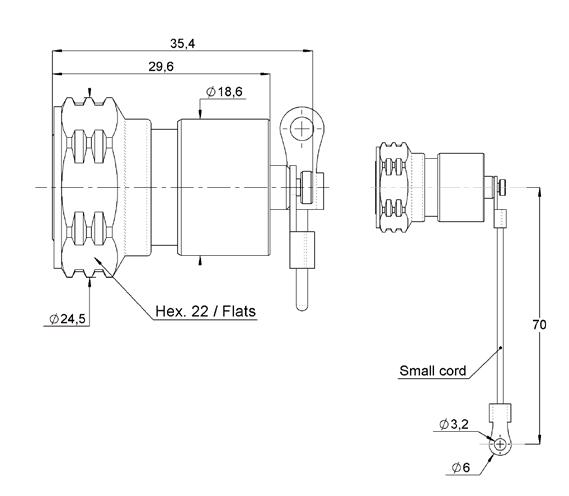
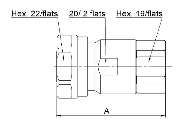
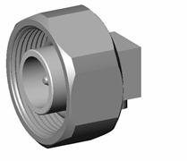
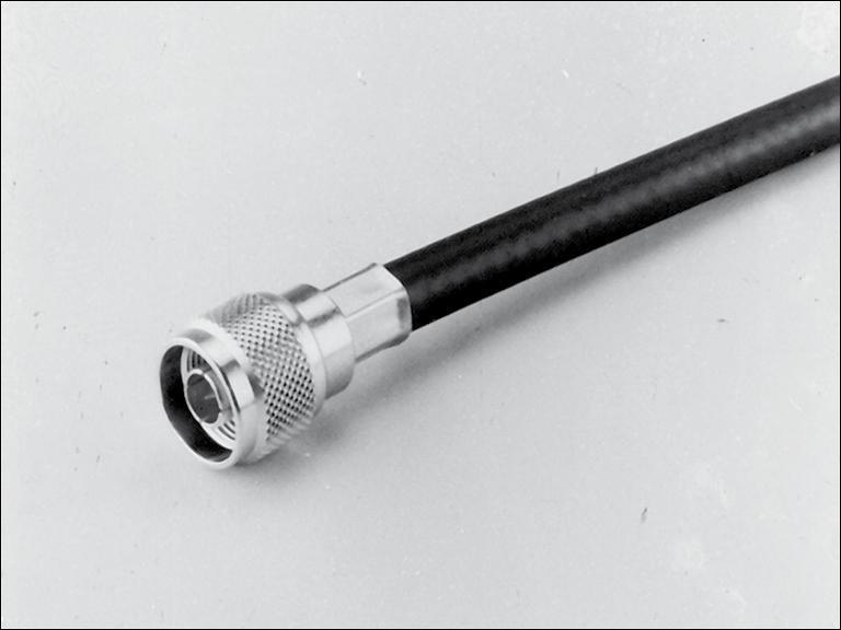
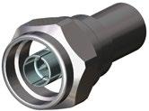
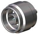
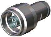
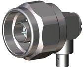
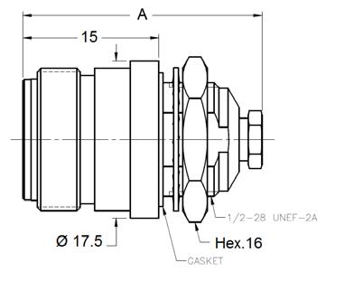
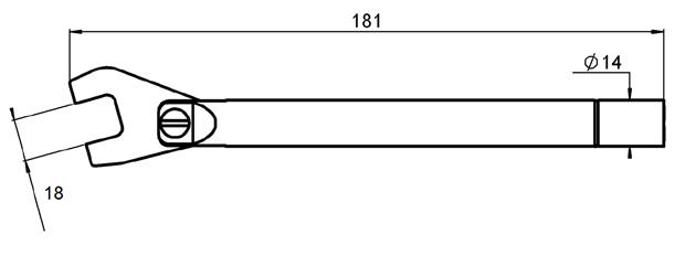
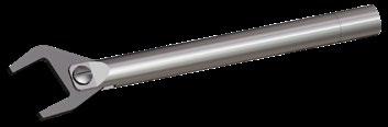
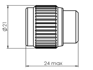
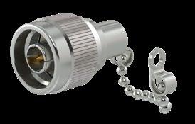
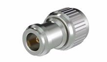
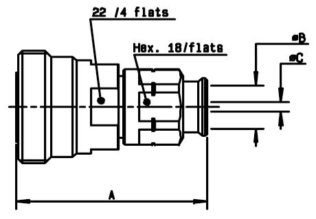
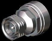
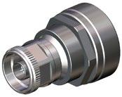
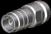
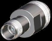
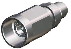
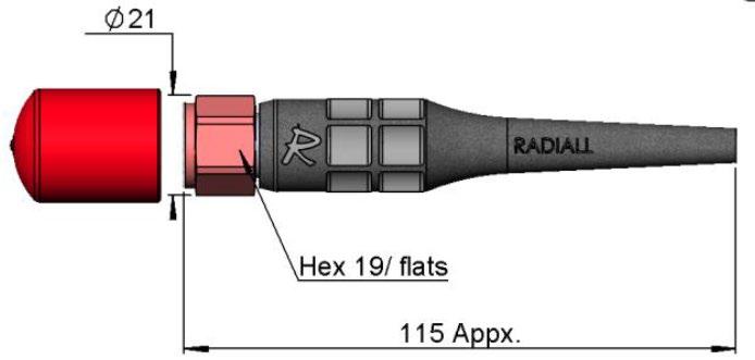
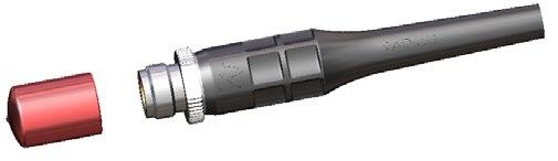
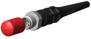
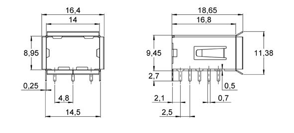
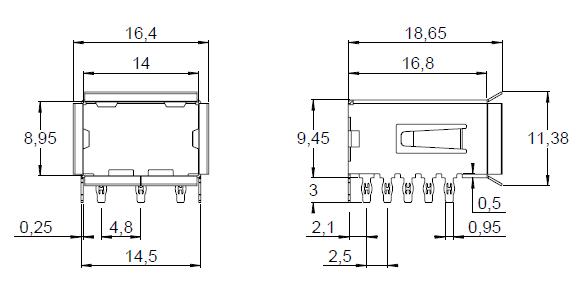
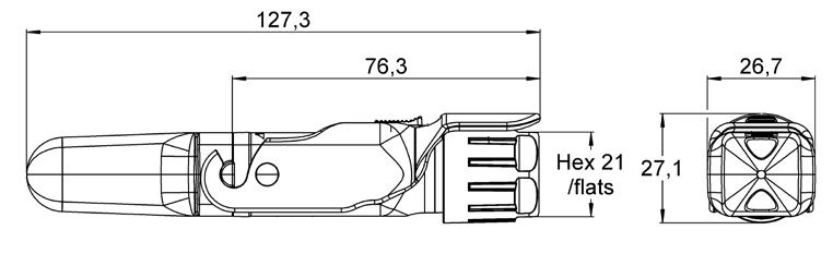
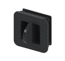
STRAIGHT PLUG SOLDER TYPE
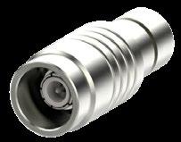
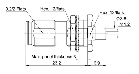
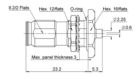
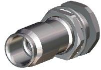
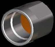
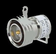
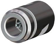
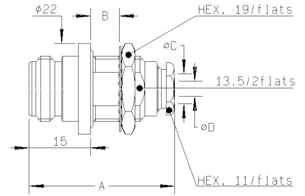
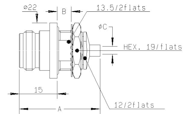
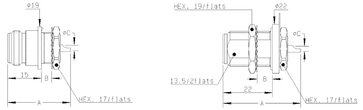
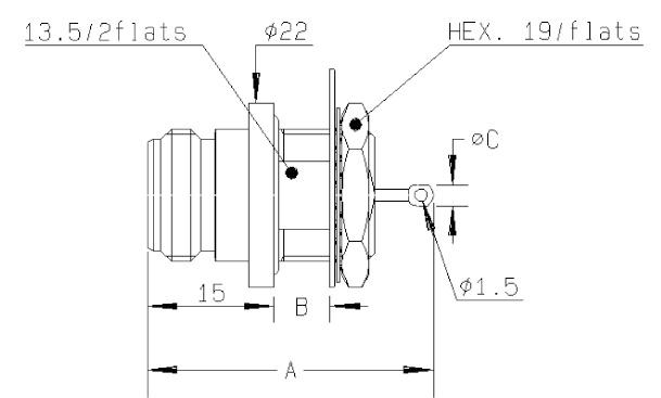
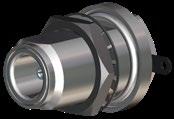
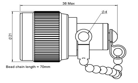
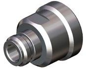
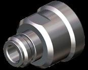
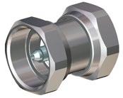
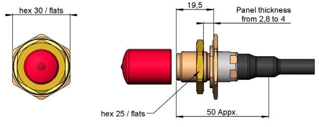
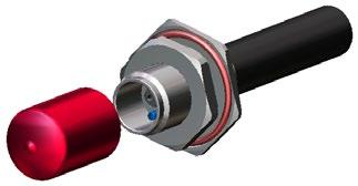
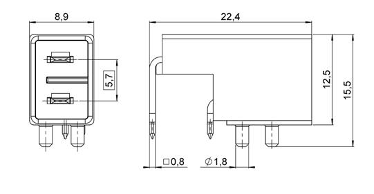
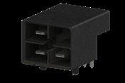
BULKHEAD JACKS
1-6 Go online for data sheets & assembly instructions. Visit www.radiall.com and enter the part number. SIMPLIFICATION IS OUR INNOVATION
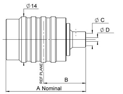
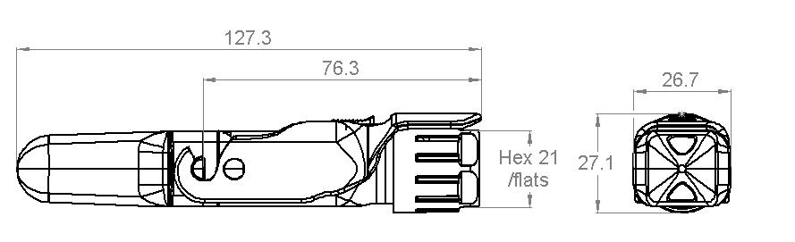
Fig. 2
™
Fig. 1
NEX10
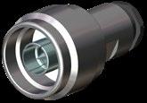
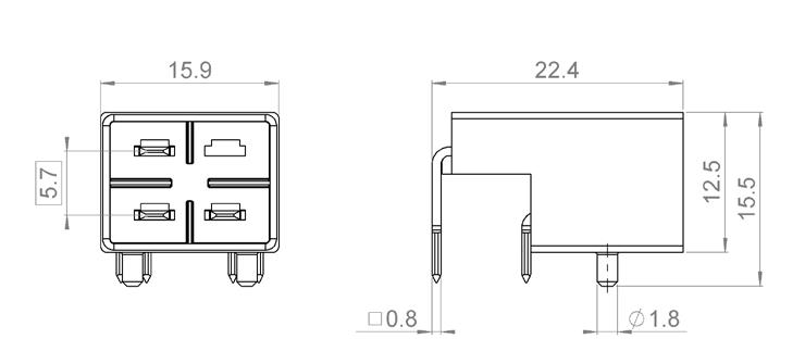
Cable group Cable group dia. Part number Fig. Finish Panel drilling Note RG402 .141 R180 300 007 1 Silver + BBR P03 Solder KS1 / RG405 .085 R180 301 007 2
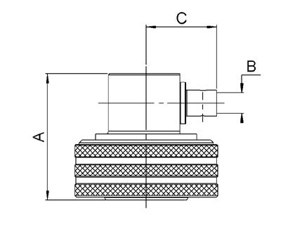
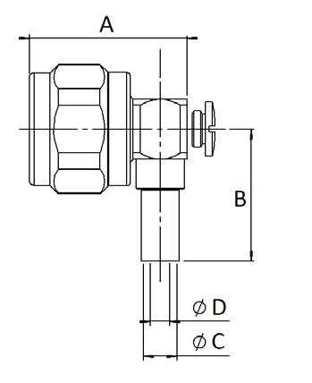
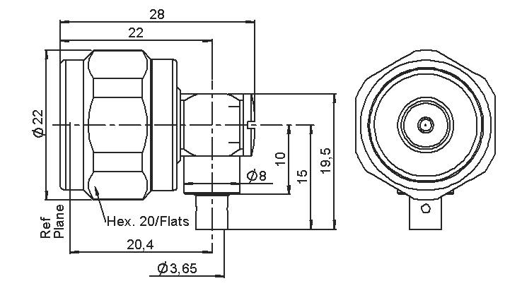
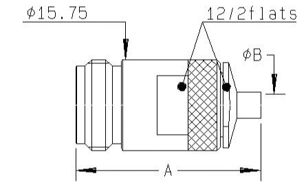
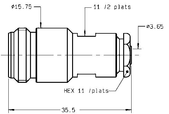
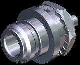
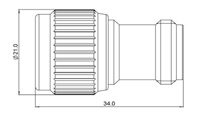
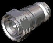
Fig. 1
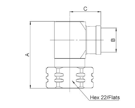
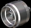
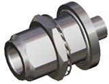
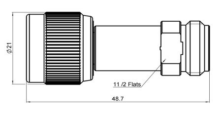
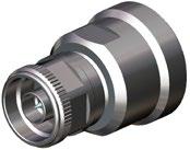
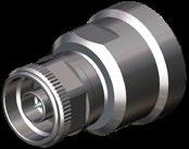
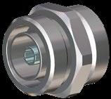
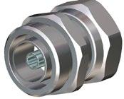
Cable group Cable group dia. Part number Fig. Dimensions Finish Coupling mechanism A B C D RG402 .141 R180 052 007 1 24.3 12.8 3.8 1.2 Silver + BBR Screw-on R180 052 017 2 Push-pull HCF 1/4" Cu2YAICu 1/4" superflexible corrugated R180 060 007 26.7 15.2 7 2 R180 060 017 1 Screw-on
Fig. 2
1-7 Go online for data sheets & assembly instructions. Visit www.radiall.com and enter the part number. SIMPLIFICATION IS OUR INNOVATION
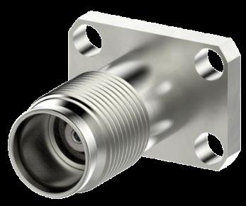
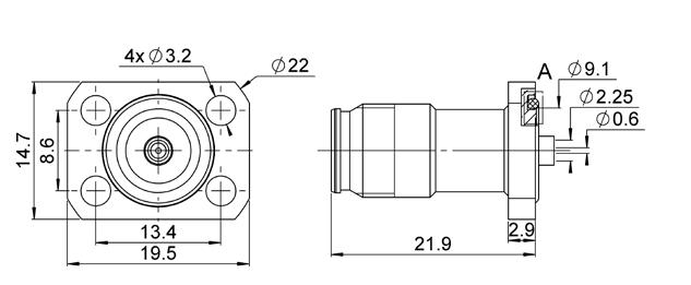
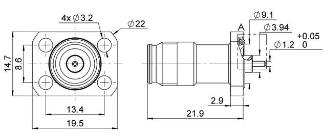
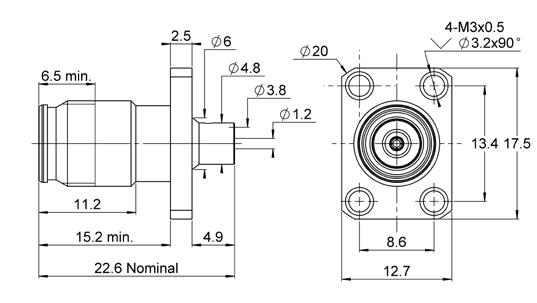
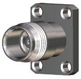
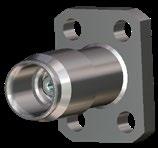
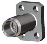
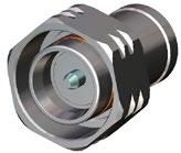
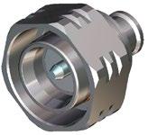
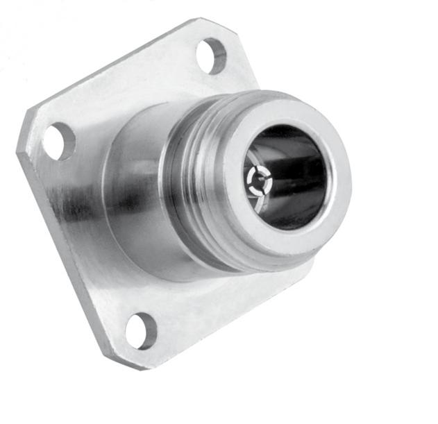
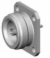
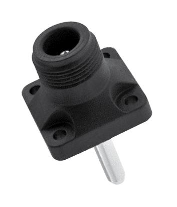
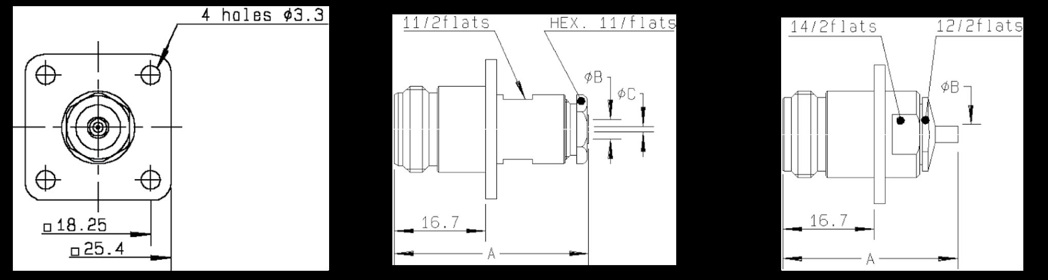
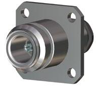
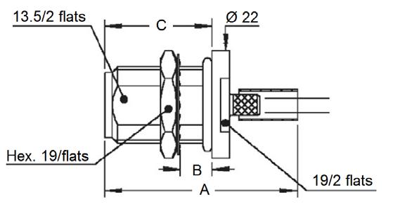
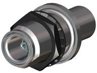
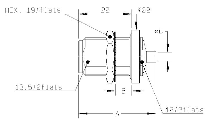
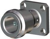
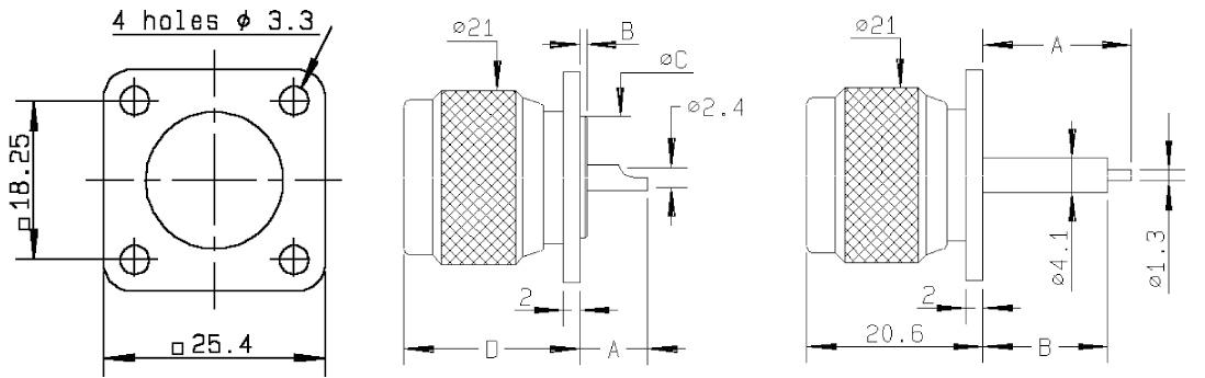
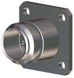
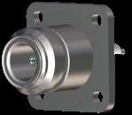
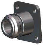
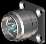
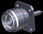
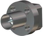
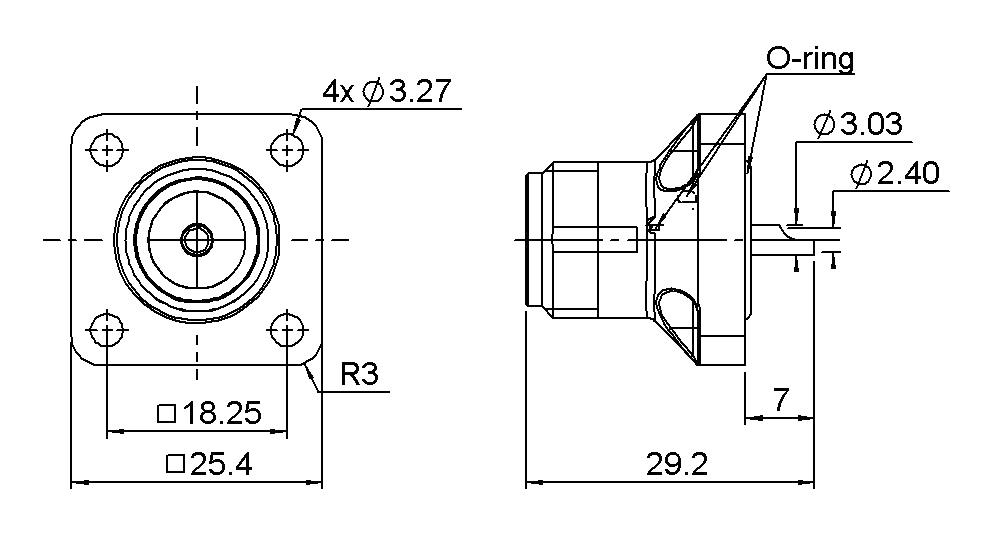
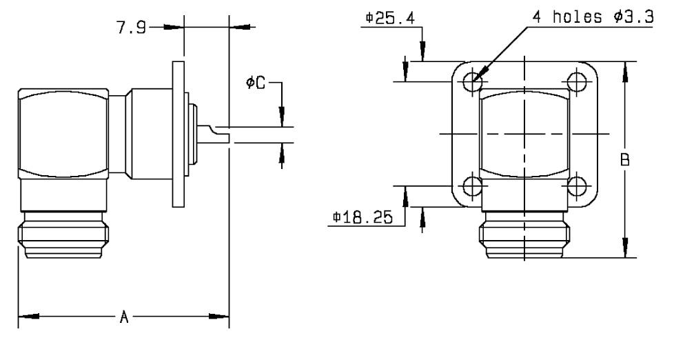
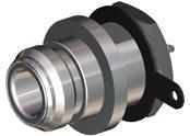
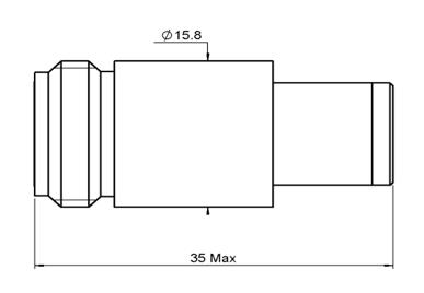
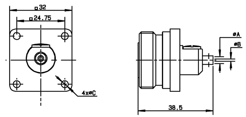
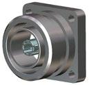
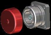
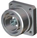
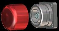
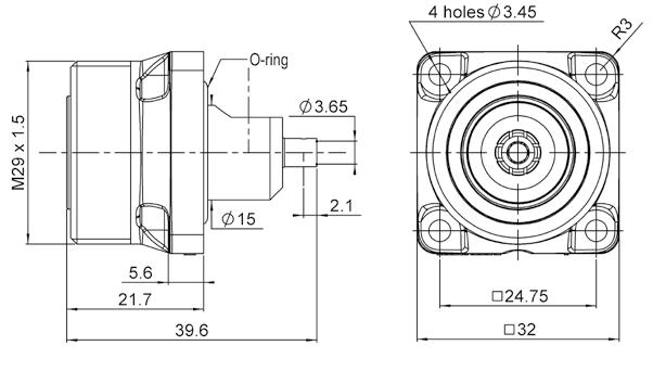
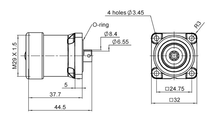
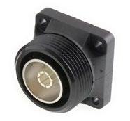
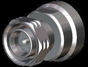
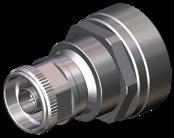
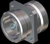
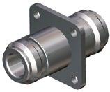
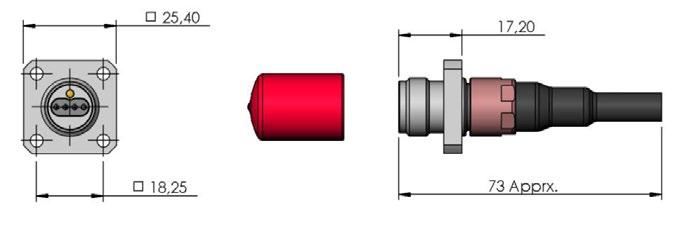
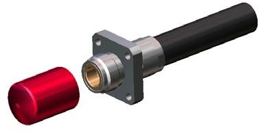
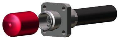
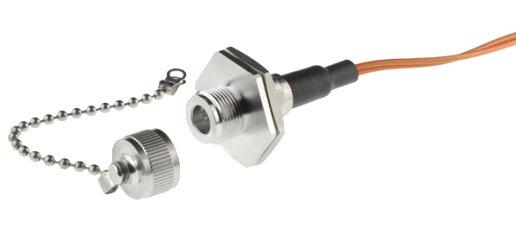
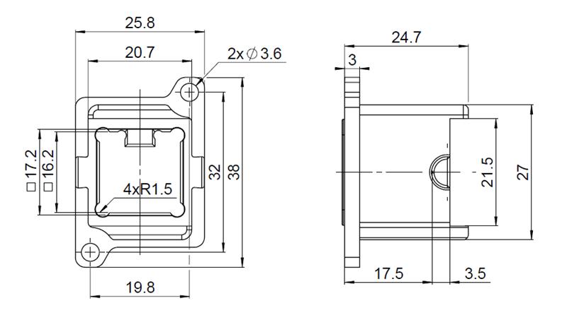
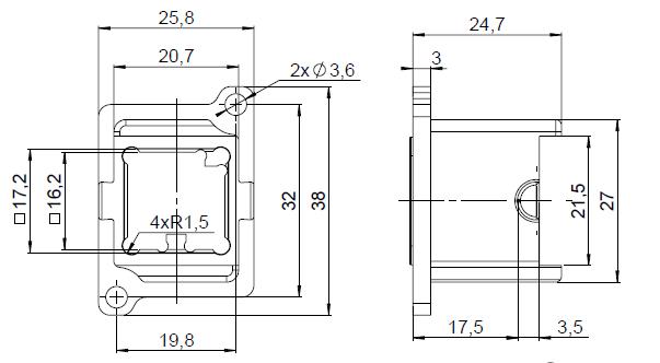
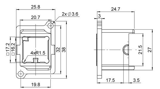
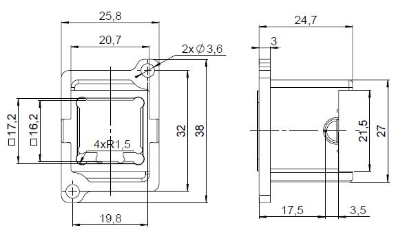
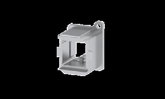
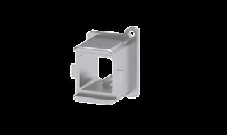
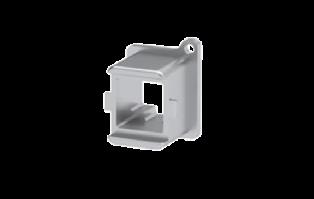
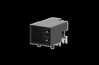
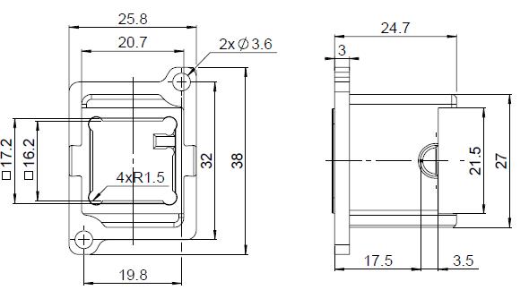
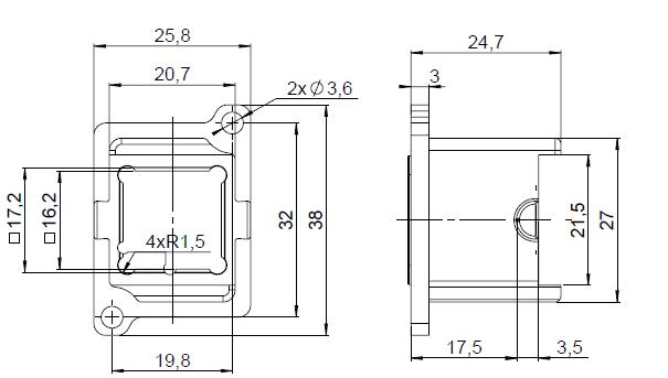
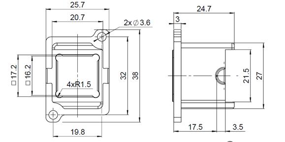
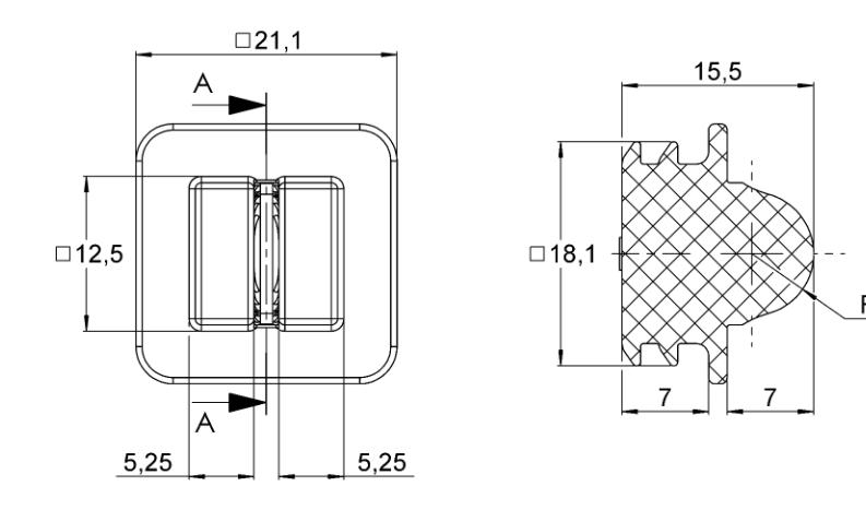
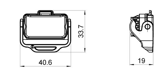
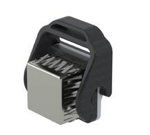
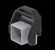
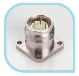
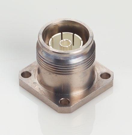
FLANGE JACKS
Fig.
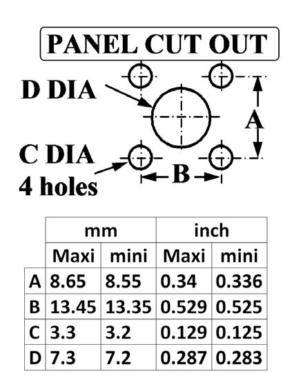
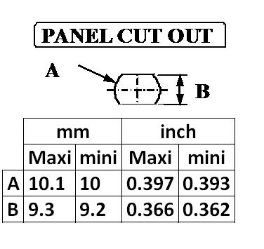
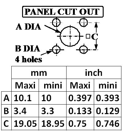
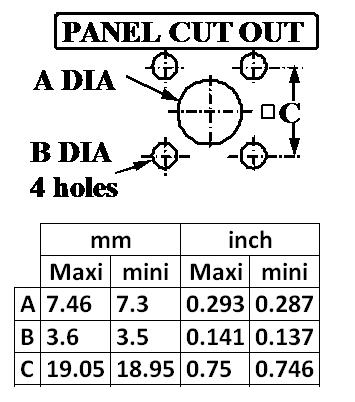
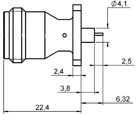
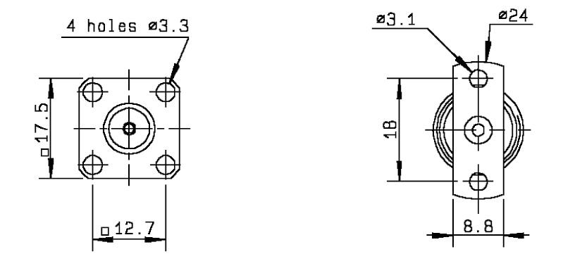
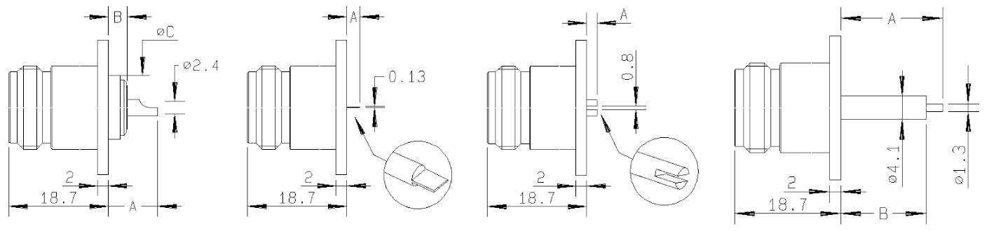
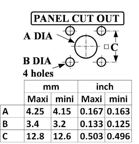
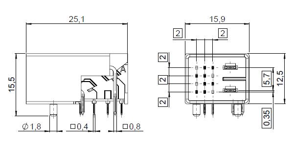
Cable group Cable group dia. Part number Fig. Finish Panel drilling Note - - R180 540 007 1 Silver + BBR P01 Pin dia 1.2 KS1 / RG405 .085 R180 415 007 2 P02 Solder RG402 .141 R180 252 007 3 Fig. 3 NEX10
Jacks
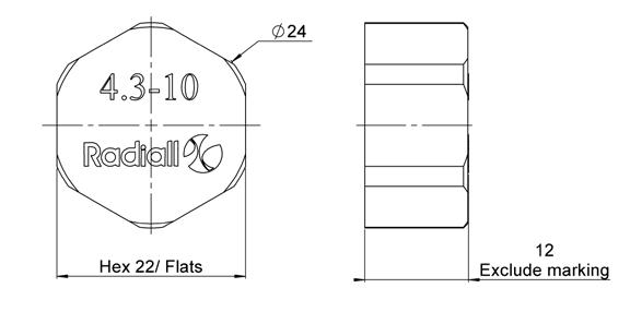
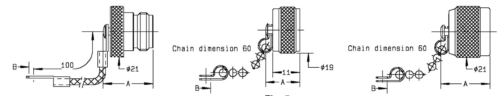
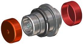
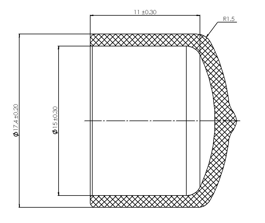
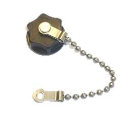
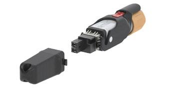
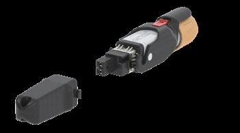
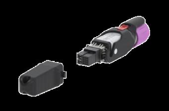
CAPS Part number Coupling mechanism Note Material R180 805 010 Screw-on IP67 ABS R180 805 007 Metal
Fig. 1
2
™
PROTECTIVE
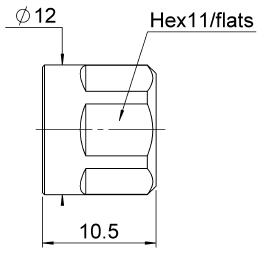
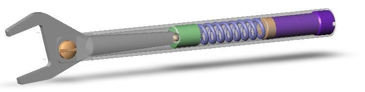
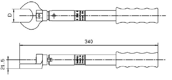
TOOLS Part number Description Across flats D (mm) R282 303 050 Torque wrench 1.5N.m 11
Accessories and Tools
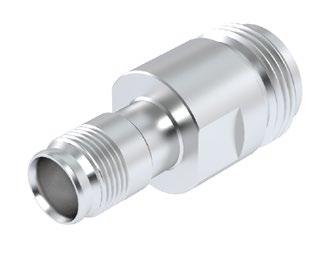
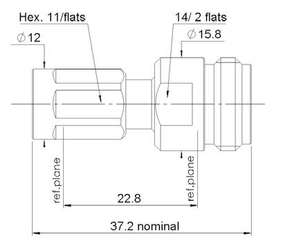
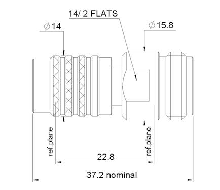
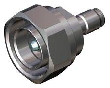
™ Between Series Adapters
R191 620 037
R191 620 027 NEX10™ Jack female N Jack female
IP67 4.3-10 Jack female


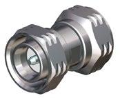
R191 620 017 7/16 Plug male
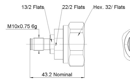
R191 621 017
SMA 3.5 Plug male

1-8 Go online for data sheets & assembly instructions. Visit www.radiall.com and enter the part number.
IS OUR INNOVATION
SIMPLIFICATION
NEX10
Part
Interface 1 Interface 2 2D Shape
number
Between Series Adapters
R191 631 007
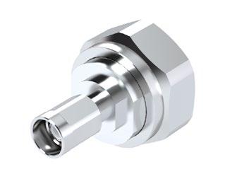
NEX10™ Screw Plug male 7/16 Plug male
R191 620 047 4.3-10 Jack female
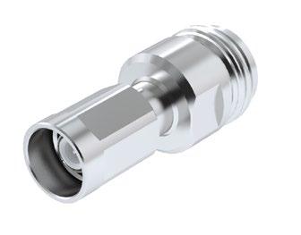
R191 630 007 N Jack female
R191 621 007 SMA 3.5 Jack female

R191 620 007
NEX10™ Push-pull Plug male N Jack female
1-9 Go online for data sheets & assembly instructions. Visit www.radiall.com and enter the part number. SIMPLIFICATION IS OUR INNOVATION
Part number Interface 1 Interface 2 2D Shape
NEX10 ™
1-10 Go online for data sheets & assembly instructions. Visit www.radiall.com and enter the part number.
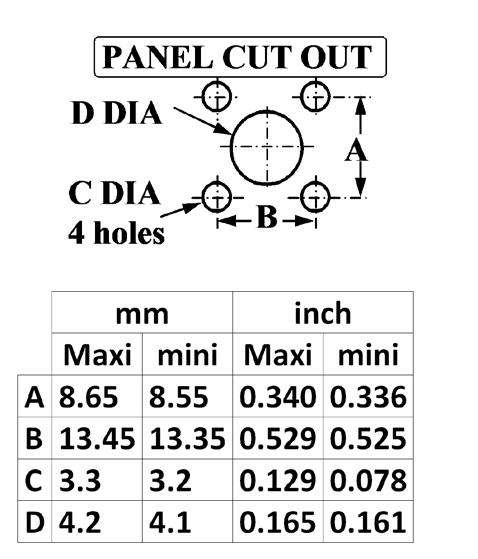
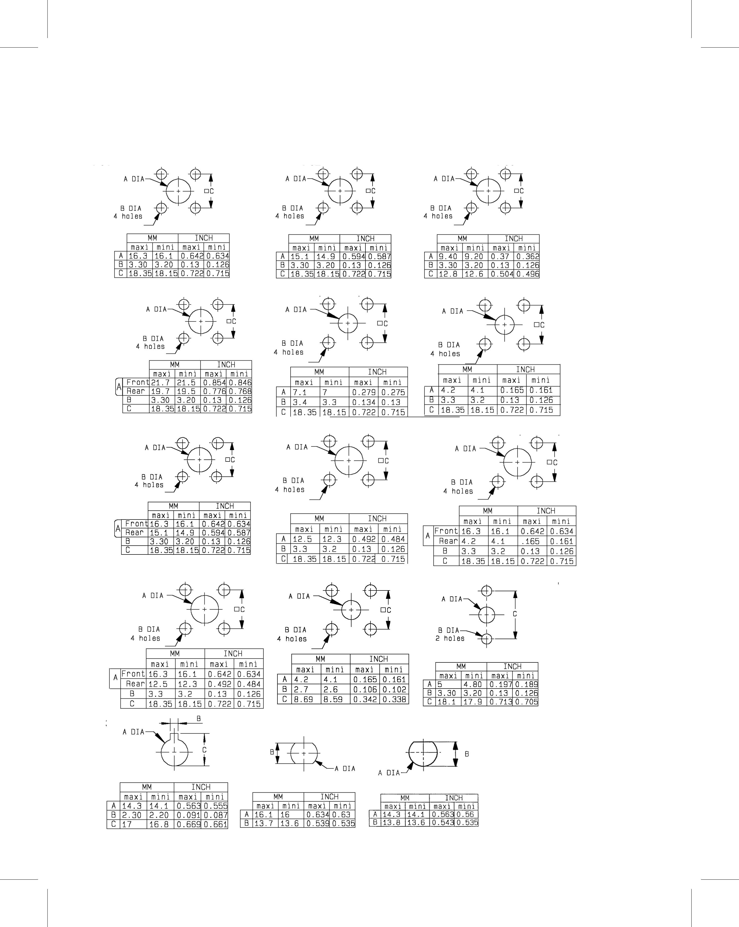
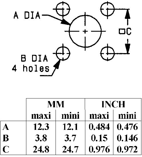
IS OUR INNOVATION P01 P02
SIMPLIFICATION
P03 NEX10 ™
Panel Drilling
SIMPLIFICATION IS OUR INNOVATON Visit www.radiall.com for more information SECTION 2
R183
4.3-10 SERIES
2-3 Go online for data sheets & assembly instructions. Visit www.radiall.com and enter the part number. SIMPLIFICATION IS OUR INNOVATION 4.3-10 Introduction 2-4 Characteristics 2-5 Plugs ..................................................................................................................... 2-6 to 2-7 Jacks 2-7 Accessories and tools 2-8 Panel drilling 2-8 Low power terminations 2-8 Medium power terminations 2-9 Medium power attenuators 2-9 SECTION 2 TABLE OF CONTENTS Contents
4.3-10
Introduction
GENERAL
• Low Intermodulation connector
• Screw-on & push-pull coupling mechanism
• High power rating
• 30% smaller & 60% lighter than 7/16
APPLICABLE STANDARDS
• IEC 61169
• MIL PRF 39012
APPLICATIONS
• Telecom
• Medical
• Industrial
• Indoor and outdoor use
Overview
Designed for major telecom equipment manufacturers, the 4.3-10 series offers a small, lightweight solution for outdoor telecom applications where high performance is essential and low intermodulation is required.
Radiall's broad product portfolio includes the 4.3-10, 4.1-9.5, 7/16 and the innovative QLI (Quick Lock Low Intermodulation) connector. These solutions are suitable for harsh environments where reliability is required.
Available in a variety of configurations including:
- Jack/Bulkhead
- Square flange receptacles and plugs
- Right angle models
- Solder, crimp and clamp models
- Screw-on and push-pull coupling mechanism
4.3-10 connectors are a lightweight solution and are 30% smaller and 60% lighter than comparable 7/16 square flange jack receptacles. The new interface features a high intermodulation level ranging from 0-6 GHz and provides a low intermodulation level at <-166dBc.
Radiall's 4.3-10 connector solution is designed in accordance with international standards and manufactured to meet environmental safety requirements.
HIGH PERFORMANCE
• Impedance 50Ω
• Frequency range DC ~ 6 GHz
• Very low intermodulation level <-166dBc
• Screw-on and push-pull coupling mechanism for safety and ease of use
• VSWR 1.04 + 0.01 √f
• Meets all requirements for IP67
• High mating life
• 3 step connection: Engage, Push & Lock
• Intuitive design concept
• Lightweight
• Reduced size allows more space for other components
• RF Power: Up to 500 W @ 2 GHz
2-4 Go online for data sheets & assembly instructions. Visit www.radiall.com and enter the part number. SIMPLIFICATION IS OUR INNOVATION
50Ω DC - 6 GHz
Characteristics
Test / Characteristics
ELECTRICAL CHARACTERISTICS
Values / Remarks
Impedance 50Ω
Frequency range
Typical VSWR
DC - 6 GHz
1.04 + 0.01 f (GHz)
Maximum insertion loss 0.05 √F (GHz) dB
Insulation resistance
5000 MΩ min
Voltage rating <=1000 Veff
Dielectric withstanding voltage >2500 Veff
Contact resistance
• Center contact
• Outer contact
Power
< 1 mΩ < 1.5 mΩ
500W @ 2 GHz
Intermodulation <165dBc (>120 dBm) 2x20W
Typical RF leakage -110dB@3 GHz; -100dB@3~6 GHz
MECHANICAL CHARACTERISTICS
Mechanical endurance 100 cycles
Mating force (push-pull version)
• Engagement force for mating
• Separation force for mating
Mating torque (tool screw type)
• Torque
Mating mechanical retention force 450 N min.
Cable retention force 350 N mini with 1/2" S cable
Vibration
ENVIRONMENTAL CHARACTERISTICS
Temperature range - 55 °C ~ + 90 °C
Moisture resistance IP67
Corrosion salt spray
MATERIALS
Connector bodies Brass
Male center contact Bronze / Brass
Female center contact Bronze
Outer contact Brass
Other metallic parts Brass
Insulators PTFE
PLATING
Bodies BBR
Outer contact BBR
Center contact Silver
* Contact us
61169-1 § 9.3.3
2-5 Go online for data sheets & assembly instructions. Visit www.radiall.com and enter the part number. SIMPLIFICATION IS OUR INNOVATION
4.3-10
<=100 N <=80 N IEC
§9.3.6
61169-1
IEC
5 N. m
61169-1 §9.3.6
10g
IEC
2 Hz to 200 Hz
48h Up to 720
HEP2R*
with
Plugs
STRAIGHT PLUG FOR FLEXIBLE AND SEMI-RIGID CABLE
RG402 / KS2 / BELDEN 1673A / HC90000(3) / SUCOFORM 141
STRAIGHT PLUGS FOR CORRUGATED CABLES
2-6 Go online for data sheets & assembly instructions. Visit www.radiall.com and enter the part number. SIMPLIFICATION IS OUR INNOVATION
Cable group dia. Part number Fig. Dimensions Captive center contact Finish Coupling mechanism Note A B C 1/2" superflexible corrugated R183 031 007 1 27.9 3.80 12.55 Yes Silver + BBR Screw-on Solder R183 031 017 2 Push-pull 1/4" superflexible corrugated R183 030 017 1 23.8 2 6.8 Screw-on R183 030 007 2 Push-pull 3/8" superflexible corrugated R183 032 007 1 25.9 2.8 9.45 Screw-on Cable group Cable group dia. Part number Dimensions Captive center contact Finish Coupling mechanism Note A B C
.141 R183 052 007 21.9 0.96 3.7 Yes Silver + BBR Push-pull Solder
Fig. 1
4.3-10
Fig. 2
Plugs
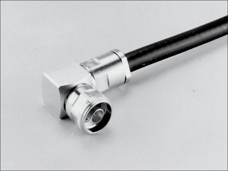
RIGHT ANGLE PLUG FOR HANDFORMABLE AND SEMI-RIGID CABLES

RIGHT ANGLE PLUG FOR CORRUGATED CABLES
Jacks
STRAIGHT SQUARE FLANGE JACKS
SQUARE FLANGE JACK RECEPTACLES

2-7 Go online for data sheets & assembly instructions. Visit www.radiall.com and enter the part number. SIMPLIFICATION IS OUR INNOVATION
Cable group Cable group dia. Part number Dimensions Captive center contact Finish Coupling mechanism Note A B C RG402 / KS2 .141 R183 197 007 21.7 3.65 12.5 Yes Silver + BBR Push-pull Solder
Cable group dia. Part number Dimensions Captive center contact Finish Coupling mechanism Note A B C 1/2"
R183 165 007 34.7 12.55 16.15 Yes Silver + BBR Screw-on Solder 4.3-10
superflexible corrugated
Cable group Cable group dia. Part number Captive center contact Panel drilling Finish RG402 .141 R183 252 007 Yes P01 Silver / BBR
Part number Captive center contact Panel drilling Finish Note R183 405 067 Yes P02 Silver / BBR Solder pot

2-8 Go online for data sheets & assembly instructions. Visit www.radiall.com and enter the part number. SIMPLIFICATION IS OUR INNOVATION 4.3-10 Accessories
Tools Part number Note R183 804 020 IP67 for mated condition UV resistance R282 303 240 Torque wrench 5N.m P01
P02
and
Panel Drilling
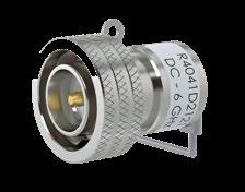
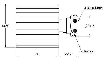
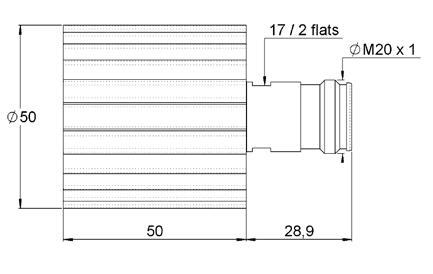
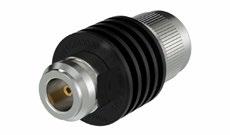
Low Power Terminations
2-9 Go online for data sheets & assembly instructions. Visit www.radiall.com and enter the part number. SIMPLIFICATION IS OUR INNOVATION
Fig. 1
Fig. 2
Fig. 3
Fig. 4
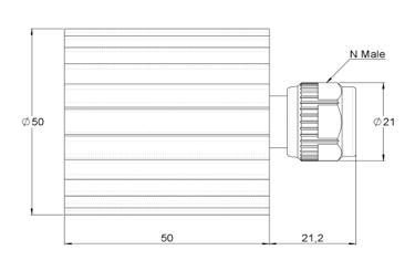
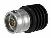
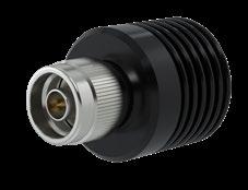
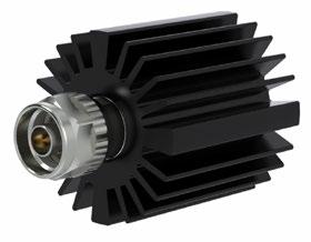
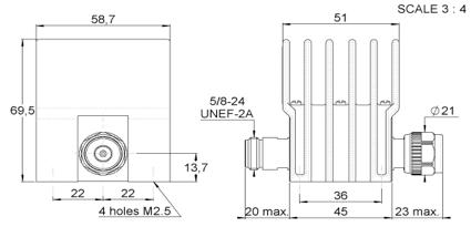
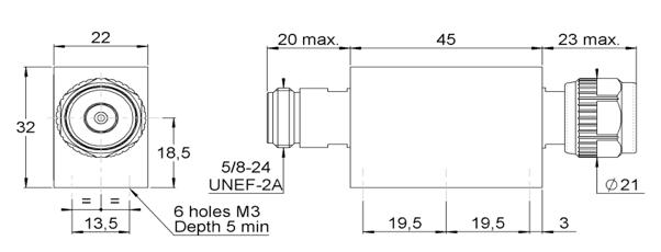
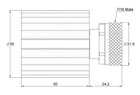
Frequency DC to (GHz) VSWR max. Return loss min. (dB) Power rating (W) Impedance (Ω) Gender Part number Fig. average peak 6 1.25 19.1 2 500 50±5% Male screw R404 1D1 000 1 R404 1D1 121(1) 2 Male push-pull R404 1D2 000 3 R404 1D2 121(1) 4 Female R404 1D5 000 5
Fig. 5
4.3-10
(1) with cord
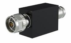
Medium Power Terminations
1 Fig. 2
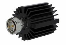
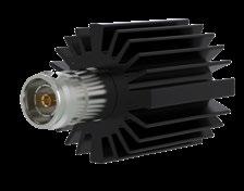
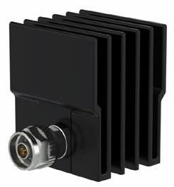
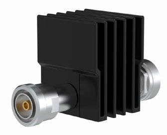
Medium Power Attenuators
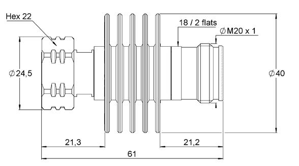
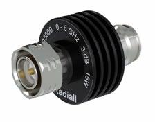
Available attenuation value: xx = 03, 06,10, 20 dB
2-10 Go online for data sheets & assembly instructions. Visit www.radiall.com and enter the part number. SIMPLIFICATION IS OUR INNOVATION
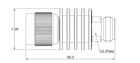
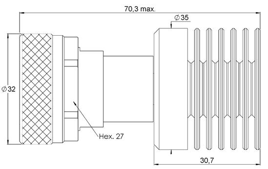
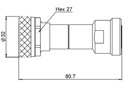
Frequency DC to (GHz) VSWR max. Return loss min. (dB) Power rating (W) Impedance (Ω) Gender Part number Fig. average peak 6 1.3 17.7 30 2,000 50±5% Male screw R404 758 000 1 Female R404 759 000 2
Fig.
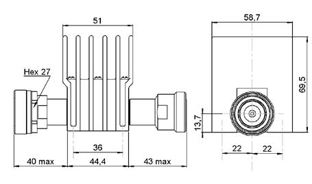
Frequency DC to (GHz) VSWR max. Return loss min. (dB) Power rating (W) Nom. Attenuation (dB) Max dev. Part number average peak 6 1.15 14.0 15 250 xx ±0.6 R415 6xx 000
4.3-10
4.1-9.5 SERIES
SIMPLIFICATION IS OUR INNOVATON Visit www.radiall.com for more information SECTION 3
R170
3-3 Go online for data sheets & assembly instructions. Visit www.radiall.com and enter the part number. SIMPLIFICATION IS OUR INNOVATION 4.1-9.5 Introduction 3-4 Characteristics 3-5 Plugs and jack ................................................................................................................... 3-6 SECTION 3 TABLE OF CONTENTS Contents
4.1-9.5
Introduction
GENERAL
• Screw-on coupling mechanism
• High power rating
• 20% smaller & 50% lighter than 7/16
• Low coupling torque
• Low intermodulation
APPLICABLE STANDARDS
• IEC 61169
• MIL PRF 39012
APPLICATIONS
• Telecom
• Medical
• Industrial
• Indoor and outdoor use
Overview
Radiall completes it's power connector range with 4.1-9.5, a low intermodulation series. 4.1-9.5 is designed to provide similar performance to 7/16 with smaller size and weight, using a proven screw-on coupling mechanism. With its corrosion resistance, Radiall 4.1-9.5 is the ideal choice for telecom applications where severe conditions require a high performance and robust connector.
HIGH PERFORMANCE
• Impedance 50Ω
• Frequency range DC ~ 6 GHz
• Very low intermodulation level <-125dBc
• Screw-on coupling mechanism
• Coupling retention force 450 N
• VSWR 1.02 + 0.02 √f
• Meets all requirements for IP67
• High mating life
• Light weight
• Reduced size allows more space for other components
• RF Power: Up to 1000 W @ 1 GHz
3-4 Go online for data sheets & assembly instructions. Visit www.radiall.com and enter the part number. SIMPLIFICATION IS OUR INNOVATION
50
DC
6 GHz
Ω
-
Characteristics
Test / Characteristics
ELECTRICAL CHARACTERISTICS
Values / Remarks
Impedance 50Ω
Frequency range 0 - 6 GHz
Typical VSWR 1.02 + 0.02 F
Maximum insertion loss 0.05 √F (GHz)
Insulation resistance 5000 MΩ min
Voltage rating <=1400 Veff
Dielectric withstanding voltage <2500 Veff
Contact resistance < 1.5 mΩ
Power 1KW @ 1 GHz
Intermodulation -160 dBc
MECHANICAL CHARACTERISTICS
Mechanical endurance 100 cycles
Disengagement force <12 N
Mating torque 1000 N.cm
ENVIRONMENTAL CHARACTERISTICS
Temperature range - 55 °C ~ + 155 °C
Sealing IP67
MATERIALS
Connector bodies Brass
Male center contact Brass
Female center contact Beryllium Copper / Bronze
Other metallic parts Brass
Insulators PTFE
PLATING
Bodies
Outer contact
Center contact Silver
4.1-9.5
3-5 Go online for data sheets & assembly instructions. Visit www.radiall.com and enter the part number. SIMPLIFICATION IS OUR INNOVATION
BBR2
BBR2
Plugs and jack
STRAIGHT PLUGS
RIGHT ANGLE PLUG
SQUARE FLANGE STRAIGHT JACK
3-6 Go online for data sheets & assembly instructions. Visit www.radiall.com and enter the part number. SIMPLIFICATION IS OUR INNOVATION
Cable group dia. Part number Fig. Dimensions Captive center contact Finish Packaging Note A B C 1/2" superflexible corrugated R170 031 107 1 31.7 12.60Yes Silver / BBR 50
type Hand formable cable .141" R170 031 007 2 22 3.65 1.05 1/2" superflexible corrugated R170 031 207 3 42 -Clamp type
Solder
Fig. 1 Fig. 2 4.1-9.5 Fig. 3
Cable group Cable group dia. Part number Dimensions Captive center contact Finish Packaging A B C RG402 Hand formable cable .141" R170 152 107 19 16 12.5 Yes Silver / BBR 50
Part number Dimensions Captive center contact Finish Packaging A B C D R170 413 127 12 8.5 11.5 1.5 Yes Silver / BBR 50
SIMPLIFICATION IS OUR INNOVATON Visit www.radiall.com for more information SECTION 4 N SERIES R161
4-3 Go online for data sheets & assembly instructions. Visit www.radiall.com and enter the part number. SIMPLIFICATION IS OUR INNOVATION N Introduction 4-4 to 4-5 Characteristics 4-6 to 4-7 Plugs . ..................................................................................................................... 4-8 to 4-9 Jacks . 4-10 to 4-12 Receptacles 4-13 to 4-16 Accessories 4-17 Tools 4-17 Panel drilling 4-18 Terminations and attenuators 4-19 to 4-21 SECTION 4 TABLE OF CONTENTS Contents
Introduction
GENERAL
• Standard coaxial connectors
• Screw-on coupling
• High durability and proven strength
• High power rating
• Excellent RF performance
APPLICABLE STANDARDS
APPLICATIONS
• Wireless communications
• Civil and military radio-telecommunication equipment
• Countermeasure
• Navy equipment
• Industrial applications
• MIL-C-39012 / MIL STD 348-304
• CEI 169-16
• CECC 22210
• NF-C-93566
• DS 8811
COMPOSITE AND SWITCHING CONNECTORS
FULL CRIMP MODELS
This reliable attachment system can be easily installed in a field environment, with easy-to-use tooling (including models for 2 and 2.6 mm dia cables). All our full crimp connectors are single piece body.
18 GHz PRECISION CONNECTORS
These connectors are suitable for medium to high power applications and precision microwave test equipment. They have long life duration and enhanced electrical performance in severe environmental conditions. N18 series mate with all 50 ohms N connectors.
LOW INTERMODULATION CONNECTORS
Radiall extensive knowledge in this field led to the development of N series connectors that are specially designed for base stations of applications where the elimination of intermodulation products is of the utmost importance. Features:
• Optimized for 900 - 1800 MHz bands (and able to work up to 11 GHz like the standard models)
• IMP3 performance = -110 dBm (- 153 dBc)
• New models for corrugated and low loss flexible cables
• High performance non magnetic materials and platings (silver and BBR)
• New 6 flats coupling nut (18 mm), allowing high coupling torque (170 Ncm) thanks to torque wrench
• Non slotted outer contact
4-4 Go online for data sheets & assembly instructions. Visit www.radiall.com and enter the part number. SIMPLIFICATION IS OUR INNOVATION N
50Ω DC - 11 GHz (standard N) DC - 18 GHz (N 18 GHz)
Introduction
Radiall offers a wide range with a standard plating finish: BBR (Bright Bronze Radiall) a high performance non-magnetic alloy.
VERY LOW INTERMODULATION CABLE ASSEMBLIES
For severe intermodulation conditions, we propose a range of low intermodulation cable assemblies IMP3 ≤ 125 dBm.
For further details, reference:
- Intermodulation application guide (D1 032 DE)
- BBR plating application guide (D1 030 DE)
IMPORTANT: The 50Ω and the 75Ω connectors are NOT INTERMATEABLE and results in the destruction of the interface.
COMPOSITE RECEPTACLES
Features and benefits:
Intermateable with standard N connectors for backward compatibility
Evenly distributed contact pressure for a better intermodulation
Composite material to remove any potential corrosion in outdoor applications
Color coding (optional)
Light material for weight saving for cost sensitive equipments
Best material selection for outstanding torque resistance
Many center contact options available for an easy adaptation to customers' applications
POWER SWITCHING CONNECTORS
This "two-in-one" solution replaces the existing standard RF switches by integrating the switch function into a receptacle connector. This solution provides a unique means of switching between two RF signal paths. As user friendly as a standard connector, the switch is mechanically activated by mating and unmating the connector.
Advantages
• Reliable
• Increases the density
• Excellent electrical and mechanical performance
• Reduction of the cost of ownership
• Betty RF adaptation
• Good isolation
• Available in right or left versions
PLATING
Radiall introduces its new composite N receptacles. Composite N connectors offer outstanding electrical performance and are the best compromise in terms of weight, cost and mechanical characteristics to replace existing brass technology.
Applications
• Telecom applications
• RF power amplifiers
Radiall offers a wide range with a standard plating finish: BBR (Bright Bronze Radiall) a high performance non-magnetic alloy.
4-5 Go online for data sheets & assembly instructions. Visit www.radiall.com and enter the part number. SIMPLIFICATION IS OUR INNOVATION
N
Characteristics
Test / Characteristics
ELECTRICAL CHARACTERISTICS
Impedance
Typical V.S.W.R. Frequency
• Straight models cable group: .085" .141" .250" 5/S+5/D 10/S+11/D • Right
Intermodulation product (IMP3)
• Standard connectors • Intermodulation connectors • Home made intermodulation cable assemblies
Insertion loss
RF leakage
Straight connector
Right-angle connector
Insulation resistance
Standard reference
Values / Remarks
-90 dB min from 2 to 3 GHz (interface)
5000 MΩ min Contact
Working voltage in VRMS
• At sea level (at 70, 000 feet)
Dielectric withstanding voltage in VRMS
• At sea level (at 70, 000 feet)
RF testing voltage Sea level
MECHANICAL CHARACTERISTICS
Cable 5/50 850 (250)
Cable .085”/.141” 350 (250)
Cable 10+11/50 1400 (400)
Cable LMR 400/600 1400 (400)
Cable .250” 1400 (400)
Cable 5/50 1500 (350)
Cable .085”/.141” 1000 (350)
Cable 10/50 2500 (600)
Cable LMR 400/600 2500 (600)
Cable .250” 2500 (600)
1500 VRMS (5 MHz sine wave)
Durability CECC 500 matings
Engagement and separation torque
6.6 Ncm max (.58 Inch-pounds)
Recommended coupling nut torque 40 to 60 Ncm (manual) 130 Ncm (11.45 inch pounds) (with pliers R 282 202 000) 170 Ncm (14.96 inch pounds) (with torque wrench R 282 303 020)
Proof torque
Coupling nut retention force
Cable retention force
Center contact retention force Axial
170 Ncm (14.96 inch pounds)
450 N (101.25 Lbs)
Cable 5/50/S 150N (33.75 Lbs)
Cable 5/50/D 200N (48 Lbs)
Cable 10/50 300N (67.5 Lbs)
Cable 11/50 400N (90 Lbs)
Cable .141” 270N (60.75 Lbs)
27 N (6.08 Lbs) cables < 8 mm
68 N (15.30 Lbs) cables > 8 mm
4-6 Go online for data sheets & assembly instructions. Visit www.radiall.com and enter the part number. SIMPLIFICATION IS OUR INNOVATION
50Ω Frequency range DC - 11 GHz
1 GHz 1.03 1.03 1.03 1.05 1.04 1.04 1.04 2.5 GHz 1.03 1.05 1.03 1.06 1.05 1.05 1.1 5 GHz 1.05 1.05 1.05 1.1 1.09 1.18 1.20 11 GHz 1.08 1.08 1.07 1.16 1.2
angle models: 5/S+D 10/S+11/D
- 90 dBm typ. (- 133 dBc typ. / 20W) - 110 dBm typ. (- 153 dBc typ / 20W) - 125 dBm typ. (- 165 dBc typ. / 20W)
•
•
MIL < 0.15 dB max at 10 GHz ~ < 0.05 √F (GHz) < 0.15 dB max at 10 GHz ~ < 0.1 √F (GHz)
MIL
resistance
Center contact
Outer contact MIL Initial 1 mΩ 0.2 mΩ After tests 1.5 mΩ -
MIL
•
•
CECC
CECC
CECC
CECC
CECC
CECC
CECC
MIL
N 50Ω
Characteristics
Test / Characteristics
ENVIRONMENTAL
Standard reference
CHARACTERISTICS
Temperature range • Standard models • Semi-rigid cables
Thermo cycling test
Thermal shock
High temperature test
Corrosion salt spray
Vibration
CECC
Values / Remarks
- 55°C + 155°C - 55°C + 105°C
CECC - 55°C/+ 155°C/21 j
CECC - 40°C/+ 155°C or - 40°C/+ 85°C – 5 cycles
CECC 125°C/1000 H
CECC 48H (Possible 720H with HEP2R*)
CECC Sinus 10g/10 – 500 Hz
Shock CECC 1/2 Sinus 50g/11 ms
Moisture resistance
• Clamp type • Crimp type
Hermetic test
Leakage
MATERIALS
IEC 529 IP 67 IP 65 (with heatshrink sleeve)
CECC 10-5 bar. cm3/s
CECC
Differential pressure 100 to 110 KPa: 1 bar cm3 / H
Body / nut / center male contact / outer contact Brass
Center female contact
Treated beryllium copper
Ferrule Brass
Insulator PTFE
Gasket Silicon elastomer
PLATING
Body • Crimp + clamp type
Standard
Intermodulation models + COAXI-KIT
• Solder type BBR Gold Silver + BBR Silver
Outer contacts / design
BBR/cross knurled BBR/hex.
Center contacts Gold Silver
Outer contacts / design BBR/slotted Silver + BBR/non slotted
PACKAGING
Packaging
*Contact us
50 pieces bulk Unit packaging
4-7 Go online for data sheets & assembly instructions. Visit www.radiall.com and enter the part number. SIMPLIFICATION IS OUR INNOVATION
N 50Ω
Plugs
STRAIGHT PLUGS, CRIMP TYPE, FOR FLEXIBLE CABLES (single piece body)

STRAIGHT PLUGS, FOR SEMI-RIGID CABLES
4-8 Go online for data sheets & assembly instructions. Visit www.radiall.com and enter the part number. SIMPLIFICATION IS OUR INNOVATION
group Cable group dia. Part number Fig. Dimensions (mm) Captive center contact A
2.6/50/S+D & LMR® 100 R161 072 000 1 39.7 Yes AEP-195FR LMR® 195 R161 082 120 2 38.5 AEP-200FR LMR® 200 R161 082 200 1 38.5 AEP-240FR LMR® 240 R161 075 030 2 38.5 AEP-400FR LMR® 400 R161 088 180 40.1
Cable
RG174 / RG316 / RD316 /AEP-100FR
N 50Ω
Fig. 2
Cable group Cable group dia. Part number Fig. Dimensions (mm) Captive center contact Note A B dia. C dia. RG405 .085” R161 050 300 3 24.4 2.25 No Solder type RG402 .141” R161 051 000 3.65 R161 052 000 1 35 5.6 3.65 Clamp type RG401 .250” R161 053 000 35.4 6.6 R161 054 000 2 24.4 6.45 Solder type
Fig. 1
Fig. 2
Fig. 3
Plugs
RIGHT ANGLE PLUGS, CRIMP TYPE, FOR FLEXIBLE CABLES
Cable
RIGHT ANGLE PLUG, SOLDER TYPE, FOR SEMI-RIGID CABLES
4-9 Go online for data sheets & assembly instructions. Visit www.radiall.com and enter the part number. SIMPLIFICATION IS OUR INNOVATION N 50Ω
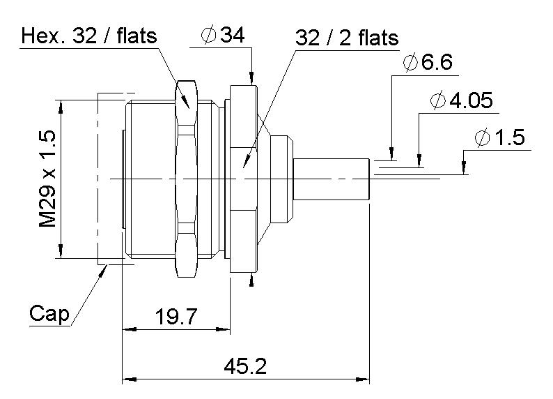
group Cable group dia. Part number Dimensions (mm) Captive center contact A B C dia. D dia. AEP-200FR LMR® 200 R161 182 080 26.3 22 5.55 3.25 Yes AEP-240FR LMR® 240 R161 183 310 26.3 24 6.6 4.05 AEP-400FR LMR® 400 R161 184 080 27 33 11.05 7.46 AEP-600FR LMR® 600 R161 188 200 31.7 39.1 15.88 11.96
group Cable group dia. Part number Captive center contact
107 Yes
Cable
RG402 .141" R161 152
STRAIGHT JACKS
SQUARE FLANGE, STRAIGHT JACKS
4-10 Go online for data sheets & assembly instructions. Visit www.radiall.com and enter the part number. SIMPLIFICATION IS OUR INNOVATION
Cable group Cable group dia. Part number Fig. Dimensions (mm) Captive center contact Note A B dia. RG402 .141" R161 226 020 1 32 3.65 No Solder type R161 227 000 2 Clamp type
Fig. 1
Fig. 2
Jacks N 50Ω
Fig. 2
Fig. 1 and 2
Cable group Cable group dia. Part number Fig. Dimensions (mm) Captive center contact Panel drilling Note A B dia. C dia. RG402 .141" R161 277 000 1 35.5 5.6 3.65 No P11 Clamp type R161 277 300 2 32 3.65 Solder type RG401 .250" R161 278 000 1 35.9 6.6 Clamp type
Fig. 2
Jacks
BULKHEAD STRAIGHT JACKS, FULL CRIMP TYPE, FOR FLEXIBLE CABLES
(panel sealed) (single piece body)
4-11 Go online for data sheets & assembly instructions. Visit www.radiall.com and enter the part number. SIMPLIFICATION IS OUR INNOVATION
N 50Ω
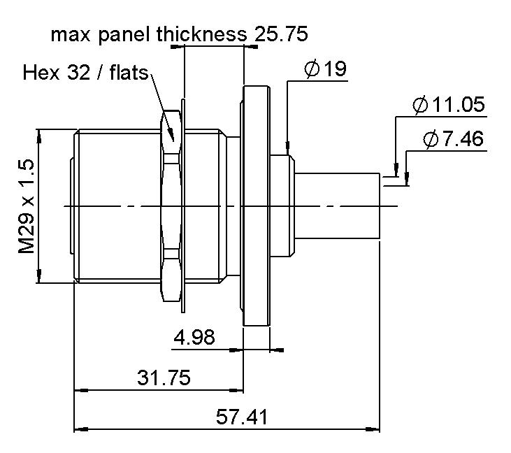
Cable group Cable group dia. Part number Dimensions (mm) Captive center contact Panel drilling Note A B C AEP-200FR LMR® 200 R161 329 130 39.8 6.5 22.2 Yes P01 Rear mount AEP-240FR LMR® 240 R161 329 140 37.8 AEP-400FR LMR® 400 R161 331 060 40.6 22 AEP-600FR LMR® 600 R161 331 400 49.9 23.7
BULKHEAD STRAIGHT JACKS, FOR SEMI-RIGID CABLES (panel sealed)
4-12 Go online for data sheets & assembly instructions. Visit www.radiall.com and enter the part number. SIMPLIFICATION IS OUR INNOVATION N 50Ω
Fig. 1
Cable group Cable group dia. Part number Fig. Dimensions (mm) Captive center contact Panel drilling Note A B RG405 .085" R161 335 200 1 32 6.5 No P11 Solder type/ Rear mount RG402 .141" R161 323 000 2 35.5 8 Clamp type/ Front mount R161 336 000 1 32 6.5 Solder type/ Rear mount R161 336 200 3 Solder type/ Front mount RG401 .250" R161 337 200 1 Solder type/ Rear mount RG405 .085" 4502-7041-010 4 26.56 Solder type/ Front mount RG402 .141" 4502-7041-009 4501-9543-009 1 33.52 Yes Solder clamp/ Rear mount
Fig. 2
Fig. 4
Fig. 3
Jacks
Receptacles
FLANGE, STRAIGHT FEMALE RECEPTACLES
4-13 Go online for data sheets & assembly instructions. Visit www.radiall.com and enter the part number. SIMPLIFICATION IS OUR INNOVATION Part number Fig. Dimensions (mm) Captive center contact Panel drilling Note A B C R161 410 000 1 + A 5.7 1.5 8.9 Yes P03 R161A 410 000 ECO version R161 410 130 4 + A P12 Solder pot contact R161 418 000 2 + A P03 Universal/See contacts page 12-22 R161 461 000 3 + B 6.2 3.9 0.6 P09 2 hole flange/Flat tab contact
Fig. 1
Fig. 4
Fig. 2
Fig. A
Fig. 3
N 50Ω
Fig. B
Receptacles
STRAIGHT MALE AND FEMALE RECEPTACLES

4-14 Go online for data sheets & assembly instructions. Visit www.radiall.com and enter the part number. SIMPLIFICATION IS OUR INNOVATION Part number Fig. Dimensions (mm) Captive center contact Panel drilling Note A B C dia D R161 404 000 1 + A 9.3 0.8 14.6 Yes P05 Solder pot R161A 404 000 Solder pot/ECO version R161 404 137 For intermodulation
Center
brass R161 416 130 4 + A 17.9 15 P06 Extended dielectric R161 419 020 2 + A 2.5 P07 Flat tab contact R161 419 300 3 + A 2 P01 Slotted contact R161 441 000 5 + A 8.7 0.8 14.6 20.6 P02 Male/Solder pot R161 441 400 6 + A 17.9 15 P04 Male/Extended dielectric R161 438 200 7 P08
application/
contact
Fig. 1 Fig. A Fig. 2 Fig. 5 Fig. 3 Fig. 6 Fig. 4 Fig. 7 N 50Ω
Receptacles
COMPOSITE FEMALE RECEPTACLES
Available upon request. Processed according to customer needs.
RIGHT ANGLE FEMALE RECEPTACLE
4-15 Go online for data sheets & assembly instructions. Visit www.radiall.com and enter the part number. SIMPLIFICATION IS OUR INNOVATION N 50Ω
Part number Captive center contact Description Color Packaging R161 404 C01 YesBlack 50 pieces R161 404 C02 Combination seal
Panel seal
R161 404 C03
Part number Dimensions (mm) Captive center contact Panel drilling Note A B C dia R161 653 000 36.9 34.4 2.5 Yes P02 Solder pot
Receptacles
BULKHEAD STRAIGHT RECEPTACLES (fully sealed or panel hermetic)

4-16 Go online for data sheets & assembly instructions. Visit www.radiall.com and enter the part number. SIMPLIFICATION IS OUR INNOVATION
N 50Ω
Part number Fig. Dimensions (mm) Captive center contact Panel drilling Note A B C R161 570 000 1 28 4.5 2.4 Yes P10 Front mount R161 606 000 2 34.6 6.5 2.4 P11 Rear mount/Fully sealed R161 625 000 3 34 6.5 2.5 Front mount/Panel hermetic
Fig. 1 Fig. 2 Fig. 3

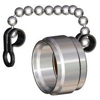
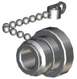
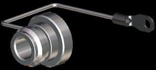
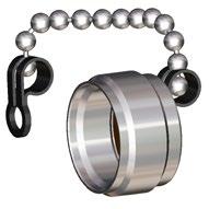


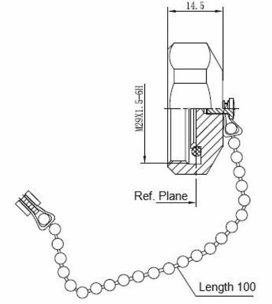
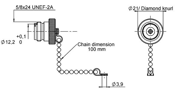
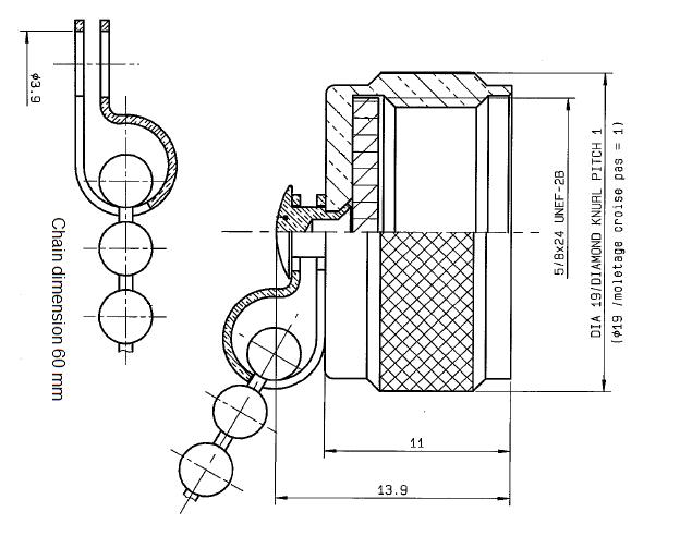
4-17 Go online for data sheets & assembly instructions. Visit www.radiall.com and enter the part number. SIMPLIFICATION IS OUR INNOVATION Part number Fig. Dimensions (mm) Note A B R161 804 000 1 13.9 3.8 Male with cord R161 805 410 2 13.9 2 Male with cord R161 841 000 3 20.4 3.9 Female with chain R161 844 000 4 20.4 3.8 Female with cord R161 853 000 5 13.9 3.9 Male with chain R161 862 000 6 20.1 Male short circuit with chain
PROTECTIVE CAPS Fig. 1 Fig. 4 Fig. 2 Fig. 5 Fig. 3 Fig. 6 N 50Ω Tools
1 Part number Fig. Description R282 202 000 1 Pump pliers R282 303 020 2 Torque wrench 18.0mm 170cm.N
Accessories
Fig.
P01 P02 P03 P04 P05 P06
P09
P07 P08
P10
P11
N 50Ω
P12
Low Power Terminations
(1) with bead chain
Medium Power Terminations

4-19 Go online for data sheets & assembly instructions. Visit www.radiall.com and enter the part number. SIMPLIFICATION IS OUR INNOVATION
Fig. 1
Fig. 2
Frequency DC to (GHz) VSWR max. Return loss min. (dB) Power rating (W) Impedance (Ω) Gender Part number Fig. average peak 4 1.2 20.8 1 500 50±2% Male R404 131 000 1 4 1.2 20.8 1 500 50±2% Male R404 131 120(1) 2 4 1.2 20.8 1 500 50±2% Female R404 132 000 3
Fig. 3
Fig. 1
Frequency DC to (GHz) VSWR max. Return loss min. (dB) Power rating (W) Impedance (Ω) Gender Part number Fig. average peak 2 1.1 26.4 6 4000 50±5% Male R404 507 000 1 2 1.1 26.4 12 4000 50±5% Male R404 557 000 2 6 1.3 17.7 30 2000 50±5% Male R404 750 000 3 6 1.3 17.7 30 2000 50±5% Female R404 751 000 4
Fig. 2
Fig. 3
N 50Ω
Fig. 4
Low Power Attenuators
Available attenuation value: xx = 00 to 15 step 1, 20, 30, 40 and 50 dB
Available attenuation value: xx = 00 to 20 dB step 1 (1) up to xx = 15
4-20 Go online for data sheets & assembly instructions. Visit www.radiall.com and enter the part number. SIMPLIFICATION IS OUR INNOVATION N 50Ω
Frequency DC to (GHz) VSWR max. Return loss min. (dB) Power rating (W) Nom. Attenuation (dB) Max dev. Part number Fig. average peak 2 1.15 23.1 2 100 xx ± 0,35 (1) R412 700 000 1
6 1.4 15.6 1 100 xx ± 0,5 (1) R412 700 124 2
Fig. 1
Fig. 2
Medium Power Attenuators
(1) up to xx = 10 (2) 12 for xx = 06 , 10 for xx = 10 and 20
4-21 Go online for data sheets & assembly instructions. Visit www.radiall.com and enter the part number. SIMPLIFICATION IS OUR INNOVATION
Frequency DC to (GHz) VSWR max. Return loss min. (dB) Power rating (W) Nom. Attenuation (dB) Max dev. Part number Fig. average peak 4 1.35 16.5 25 5000 xx ± 0,6 (1) R417 303 110 1 Available attenuation value: xx = 03, 06, 10, 20 and 30 dB 4 1.35 16.5 30 5000 xx ± 0,6 (1) R417 303 130 2 Available attenuation value: xx = 03, 06, 10, 20 and 30 dB 8 1.25 19.1 15 (2) 250 xx ± 0,3 R415 703 000 3 Available attenuation value: xx = 03, 06, 10 and 20 dB
Fig. 1
Fig. 2
N 50Ω
Fig. 3
SIMPLIFICATION IS OUR INNOVATON Visit www.radiall.com for more information SECTION 5
R185
7/16 SERIES
5-3 Go online for data sheets & assembly instructions. Visit www.radiall.com and enter the part number. SIMPLIFICATION IS OUR INNOVATION 7/16 Introduction 5-4 to 5-5 Characteristics 5-6 to 5-7 Plugs . ............................................................................................................................ 5-8 Jacks . 5-8 to 5-9 Receptacles 5-10 to 5-11 Accessories and tools 5-12 Panel drilling 5-12 Terminations 5-13 Attenuators . 5-14 SECTION 5 TABLE OF CONTENTS Contents
GENERAL
• Standard coaxial connectors
• Screw-on coupling
• High power rating
• Excellent RF performance
APPLICABLE STANDARDS
• IEC 169-4
• DIN 47223
• CECC 22 190
APPLICATIONS
• Mobile communication infrastructure networks: combiner, diplexer, filter...
• Jumper and feeder cables assemblies
• Radio links
• Indoor and outdoor applications
Radiall’s 7/16 series has been developed using the latest technology advances in connector design. These connectors are easy to use, highly reliable, innovative and designed to meet the needs of the telecommunications market. The complete connector series features:
• An extensive range, with optimized component part design
• An upgraded cross-knurled coupling nut allowing better manual tightening
Composite 7/16
Radiall expanded its line of innovative 7/16 composite connectors with jacks and receptacles as a lightweight, low cost alternative to brass connectors. Manufactured with corrosion-proof, composite materials these new single-piece connectors are UV resistant, meeting IEC 68-2-5 and IEC-68-2-9 to withstand all environments, including harsh outdoor installations. Radiall now offers over 20 different variations. The selection of the composite materials is a result of an in-depth competitive analysis of creeping speeds of zinc and aluminum alloys. Not only do the composite materials offer considerable performance advantages guaranteeing up to 500 matings, but with more than a 50% reduction in weight, this receptacle reduces the overall weight of the final module as well as transportation costs.
5-4 Go online for data sheets & assembly instructions. Visit www.radiall.com and enter the part number. SIMPLIFICATION IS OUR INNOVATION
50Ω DC - 7.5 GHz
7/16
Introduction
Introduction
High performance range
• Frequency range: DC - 7.5 GHz
• 2 types of coupling nut:
- Cross-knurled and 6 flats 27mm wide coupling nut (3 000 N.cm)
- 6 flats coupling nut (32mm wide), allowing high coupling torque (3 500 N.cm) when used with a torque wrench
• Intermodulation performance: 2 levels
- 125 dBm cable assemblies
- 110 dBm connectors and cable assemblies
2 types of coupling nut
Radiall has developed its intermodulation measurement equipment following the IEC 46 D/292/NP standard proposal. It is aimed at third-order IMP measurements through the reflection method. The range of this test set-up is -132 dBm (-175 dBc) under 2 x 20 W.
• High performance non-magnetic material (brass) and plating (silver) with anti-tarnishing finish (strike of BBR)
• Non-slotted outer contact on standard products
• The 7/16 connector series benefits from a complete easy-to-use range of tooling
Custom models
To fulfill customer requirements, Radiall offers complete design of custom connectors according to the 7/16 series standard.
5-5 Go online for data sheets & assembly instructions. Visit www.radiall.com and enter the part number. SIMPLIFICATION IS OUR INNOVATION
7/16
Characteristics
Test / Characteristics
ELECTRICAL CHARACTERISTICS
Impedance
Straight models
RG213-RG214-RG393 .141” .250”
1/2” superflexible corrugated
3/8” superflexible corrugated 1/4” superflexible corrugated
• Right angle models
RG213-RG214-RG393
1/2” superflexible corrugated
3/8” superflexible corrugated 1/4” superflexible corrugated
Intermodulation product (IMP3)
Connectors
Home made cable assemblies
Insertion loss (dB)
Straight connectors and right-angle connectors
Leakage
Contact
•
Working voltage in VRMS at sea level
Dielectric withstanding voltage in VRMS
• At sea level (at 70, 000 feet)
MECHANICAL CHARACTERISTICS
Durability
Force to engage and disengage
Recommended coupling nut torque
• Hex. coupling nut
• Hex. + cross knurl coupling nut
Coupling nut retention force
Cable retention force
Cable 5/50 & 10/50
Cable 1/4”
Cable 3/8”
Cable 1/2”
Cable 7/8”
Center contact retention force
ENVIRONMENTAL CHARACTERISTICS
Temperature range
• Flexible cables and corrugated cables
• Semi-rigid cables
Thermo cycling test
Rapid change of temperature
High temperature test
Corrosion salt spray
Vibration
Moisture resistance
• Clamp type
• Crimp type
• Home made cable assemblies
Hermetic test
Leakage
* Contact us
(with heatshrink sleeve)
(overmolding)
5-6 Go online for data sheets & assembly instructions. Visit www.radiall.com and enter the part number. SIMPLIFICATION IS OUR INNOVATION
50Ω
range DC - 7.5 GHz Typical V.S.W.R. 1 GHz 2.5 GHz 5 GHz 7.5 GHz •
1.10 max from DC to 3 GHz - 1.20 max from 3 to 7.5 GHz
Frequency
1.04 1.04 1.03 1.02 1.03 1.01 1.06 1.07 1.05 1.04 1.03 1.02 1.08 1.08 1.11 1.05 1.12 1.09 1.10 1.20 1.13 1.05 1.20 1.17
1.15 max from DC to 3 GHz
1.02 1.04 1.05 1.02 1.04 1.04 1.08 1.06 1.12 1.14 1.12 1.13 1.50 1.60 1.80 1.60
•
-110 dBm typ. (- 153 dBc typ / 20 W) -125 dBm typ. (- 168 dBc typ. / 20 W)
•
MIL 0.05 √F (GHz) RF
CECC 130 dB at 1 GHz Insulation resistance CECC 10 000 MΩ min
resistance
Center contact • Outer contact CECC < 0.4 mΩ ≤ 1.5 mΩ
CECC 2 700
CECC 4 000 350
CECC 500 matings
CECC 15 N
3 500 Ncm (with torque wrench R 282 303 500) 3 000 Ncm (with torque wrench R 282 303 520) Proof torque CECC 3 500 Ncm
CECC 1 000 N
CECC 250 N 200 N 250 N 350 N 500 N
CECC 200 N
CECC - 55 °C + 155 °C - 55 °C + 105 °C
CECC - 55 °C / + 155 °C
56 days
/
IEC - 55 °C / + 155 °C / 5 cycles
CECC 1000 hours / 155 °C
IEC 48 hours / Na Cl 5% / 35 °C
720h
(Up to
with HEP2R)*
CECC 98 m/s2
500 Hz
- 10 Hz at
IEC
IP67 IP65
IP68
529
IEC 5 Pa.
cm3/s
CECC 1 cm3/h max
Standard
reference Values / Remarks
7/16
Characteristics
MATERIALS AND PLATINGS
Gasket
POWER RANGE
Characteristics Composite 7/16
ELECTRICAL CHARACTERISTICS
High working voltage
Very low intermodulation
< -125 dBm under 2 carriers of +43dBm And typically < -130 dBm
Power handling > 800 W@ 935 MHz
MECHANICAL CHARACTERISTICS
Longlife duration up to 500 mating cycles
Coupling torque 35 Nm or less
Coupling strength 1000 N
Center contact retention / axial force > 200 N
Center contact retention / torque > 80 Ncm
ENVIRONMENTAL CHARACTERISTICS
5-7 Go online for data sheets & assembly instructions. Visit www.radiall.com and enter the part number. SIMPLIFICATION IS OUR INNOVATION
7/16
Materials Plating Bodies Brass Silver + BBR Nut Brass BBR Center contact • Male • Female Brass Beryllium copper Silver Insulator PTFE
Silicon rubber
DC - 7.5 GHz VSWR 1.06@DC-3 GHz - 1.10@DC - 3-7.5 GHz
Frequency range
> 2700 V
IMP3
UL94-VO UV resistance IEC 68-2-5 / IEC 68-2-9
Temperature range -40°C / +85°C Humidity Up to 100% @ 20°C Flammability rating
Waterproof IP67
Plugs and Jacks
STRAIGHT PLUGS, FOR FLEXIBLE AND SEMI-RIGID CABLE


STRAIGHT JACKS
5-8 Go online for data sheets & assembly instructions. Visit www.radiall.com and enter the part number. SIMPLIFICATION IS OUR INNOVATION
Fig. 1
Fig. 2
7/16 Cable group Cable group dia. Part number Fig. Dimensions (mm) Captive center contact Finish Note A B C D RG401 .250” R185 054 020 1 Silver + BBR Solder Type AEP-240FR LMR® 240 R185 083 310 2 51.15 1.5 4.05 6.6 Yes BBR Clamp type AEP-400FR LMR® 400 R185 085 007 49.55 2.82 7.46 11.05 AEP-600FR LMR® 600 R185 077 010 58.05 4.7 11.96 15.88 Cable group dia. Part number Dimensions (mm) Captive center contact Finish Note A B C 1/4” superflexible corrugated R185 215 200 49.45 7.95 4.7 Yes Silver + BBR Clamp type 1/2” superflexible corrugated R185 216 200 50 14 8.8 3/8” superflexible corrugated R185 217 200 11 7.1
Jacks
STRAIGHT SQUARE FLANGE JACK
STRAIGHT BULKHEAD JACKS FOR FLEXIBLE CABLES AND CORRUGATED CABLES
5-9 Go online for data sheets & assembly instructions. Visit www.radiall.com and enter the part number. SIMPLIFICATION IS OUR INNOVATION
7/16 Cable group Cable group dia. Part number Captive center contact Dimensions (mm) Panel drilling Finish Note A B C RG402 .141” R185 252 000 Yes 3.65 0.996 3.6 P01 Silver + BBR Solder type for semi-rigid cables
Fig. 2
Cable group Cable group dia. Part number Fig. Captive center contact Panel drilling Finish Note AEP-240FR LMR® 240 R185 314 100 1 Yes P02 BBR Clamp type AEP-400FR LMR® 400 R185 320 020 2
Fig. 1
Receptacles
STRAIGHT FLANGE FEMALE RECEPTACLES
5-10 Go online for data sheets & assembly instructions. Visit www.radiall.com and enter the part number. SIMPLIFICATION IS OUR INNOVATION
Fig. 3
Fig. 4
Fig. 5
Fig. 2
Fig. 1
7/16 Part number Fig. Captive center contact Panel drilling Finish Slotted outer contact Packaging Note R185 403 547 1 Yes P03 BBR No 20 With solder pot contact R185 405 200 2 P05 Silver + Copper Yes Panel seal flange mount R185 406 090 3 BBR No 50 M3 R185 404 200 4 Silver + Copper 20 With slotted contact R185 403 490 5 P04 20 With tab contact
Receptacles
SQUARE FLANGE JACK RECEPTACLE SOLDER TYPE, PANEL SEAL
SQUARE FLANGE JACK RECEPTACLE PANEL SEAL


Available packaged in increments of 20
5-11 Go online for data sheets & assembly instructions. Visit www.radiall.com and enter the part number. SIMPLIFICATION IS OUR INNOVATION
Cable group Cable group dia. Part number Fig. Panel drilling RG402 .141" R187 403 010 1 P06 RG401 .250" R187 130 000 2
Fig. 1
Fig. 2
Part number Fig. Captive center contact Waterproof interface Color Panel drilling R187 403 000 1 No No Black P06 R187 403 100 Yes R187 406 000 Yes No R187 406 100 Yes R187 413 000 2 No No R187 413 100 Yes R187 416 000 Yes No R187 416 100 Yes
Fig. 1
Fig. 2
customer needs *
inside, only on the waterproof models 7/16
units Processed according to
O-ring
TORQUE WRENCH 32mm
Panel Drilling
5-12 Go online for data sheets & assembly instructions. Visit www.radiall.com and enter the part number. SIMPLIFICATION IS OUR INNOVATION PROTECTIVE CAP Part Number Note R185
Male
chain Accessories
7/16
812 007
with
and Tools
P01 P04 P02 P05 P03
Part Number Accross flats D (mm) Coupling torque (N.cm) R282 303 500 32 (1.260) 3500
Low Power Terminations

Medium Power Terminations
5-13 Go online for data sheets & assembly instructions. Visit www.radiall.com and enter the part number. SIMPLIFICATION IS OUR INNOVATION
7/16
Fig. 1
Frequency DC to (GHz) VSWR max. Return loss min. (dB) Power rating (W) Impedance (Ω) Gender Part number Fig. average peak 4 1.15 23.1 2 500 50±5% Male R404 170 111 1 Female R494 175 111 2
Fig. 2
Fig. 1
Frequency DC to (GHz) VSWR max. Return loss min. (dB) Power rating (W) Impedance (Ω) Gender Part number Fig. average peak 6 1.3 17.7 30 2,000 50±5% Male R404 756 000 1 4 1.2 20.8 12 5,000 R494 564 000 2
Fig. 2
Low Power Attenuators
Available
Medium Power Attenuators
Available attenuation value: xx- 03, 06, 10 and 20 dB. (1) ±0,6 for xx = 20
5-14 Go online for data sheets & assembly instructions. Visit www.radiall.com and enter the part number. SIMPLIFICATION IS OUR INNOVATION
Frequency DC to (GHz) VSWR max. Return loss min. (dB) Power rating (W) Nom. Attenuation (dB) Max dev. Part number average peak 3 1.3 17.7 1 100 xx ±0,5(1) R412 806 000
attenuation value: xx- 03, 06, 10 and 20 dB. (1) ±1 for xx = 20
Frequency DC to (GHz) VSWR max. Return loss min. (dB) Power rating (W) Nom. Attenuation (dB) Max dev. Part number average peak 4 1.35 16.5 25 5,000 xx ±0,6(1) R420 303 110
7/16
SIMPLIFICATION IS OUR INNOVATON Visit www.radiall.com for more information SECTION 6
SERIES R296
JUMPER
6-3 Go online for data sheets & assembly instructions. Visit www.radiall.com and enter the part number. SIMPLIFICATION IS OUR INNOVATION Jumpers Introduction
SECTION 6 TABLE OF CONTENTS Contents
6-4 to 6-5
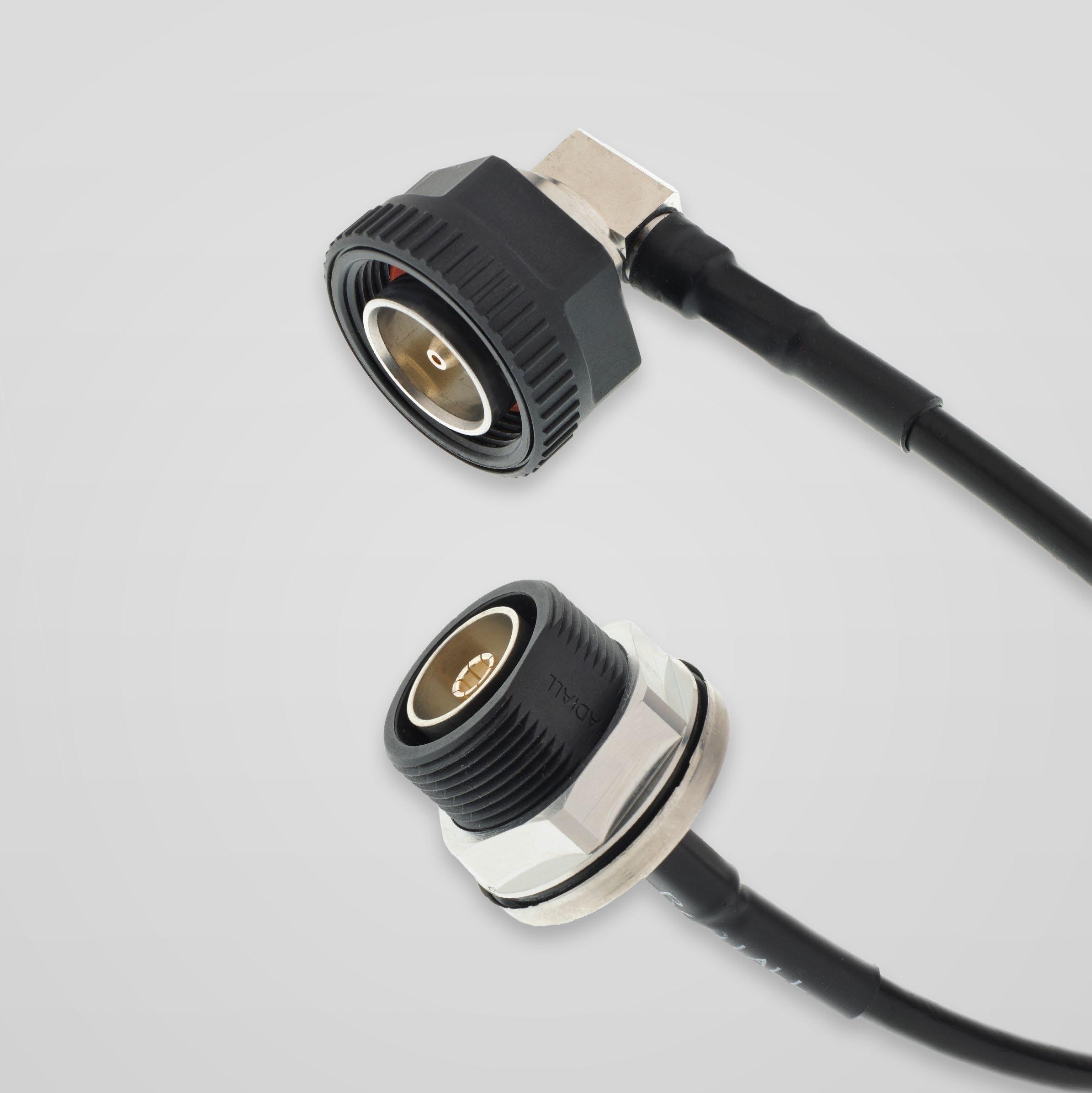
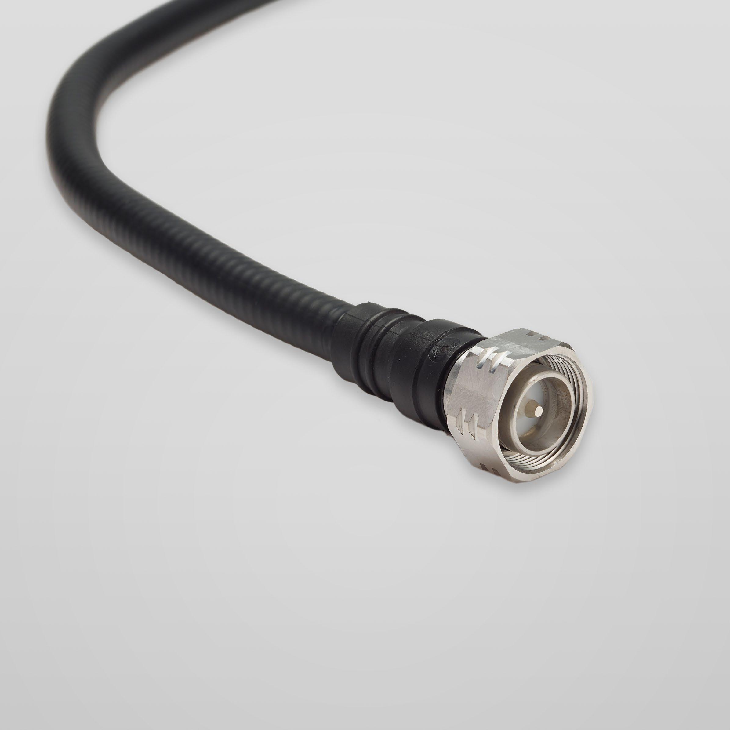
JUMPERS
Introduction
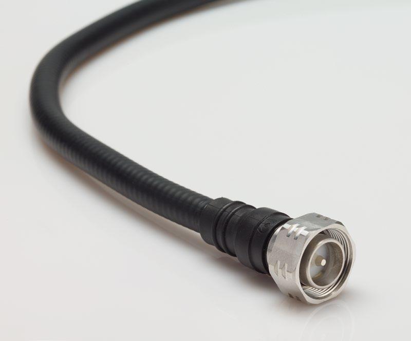
As a prime supplier to the Telecommunications industry, Radiall introduces an expanded range of Low PIM cable jumpers. These cost competitive jumpers provide excellent electrical and mechanical performance to support the demanding needs of the wireless installation market.
FEATURES
• Excellent electrical and mechanical performance
• Low passive intermodulation (PIM)
• Low return loss
• High shielding effectiveness
• High flexibility and tight bending radius
• Waterproof - meets or exceeds IP67
• 100% tested for PIM, VSWR and IL
• Black LSZH PE Jacket
• 1/2’’ and 3/8’’ superflexible corrugated cable types (**)
• Available with 4.3-10, 7/16 and NEX10 connectors (**)
SPECIFICATIONS
• 50Ω ±2Ω
• DC ~ 3GHz
• VSWR: 1.15 max.
• PIM3: ≤-160dBc @ 1800MHz 2x20W
Static & dynamic conditions (IEC 62037-2)
• Static bending radius: 27mm (1/2”) - 25mm (3/8”) cables
• Mechanical endurance: 100 Cycles
• Temperature range: -40 to +85°C
• RoHS Compliant
** Other connector and cable styles available upon request.
6-4 Go online for data sheets & assembly instructions. Visit www.radiall.com and enter the part number. SIMPLIFICATION IS OUR INNOVATION
Introduction
Radiall’s low intermodulation cable jumper solutions are suitable for indoor or outdoor cabling to base stations and antenna systems.


JUMPERS
3.5
6-5 Go online for data sheets & assembly instructions. Visit www.radiall.com and enter the part number. SIMPLIFICATION IS OUR INNOVATION
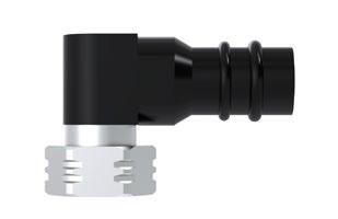
4.3-10 Straight Fig. 1 4.3-10 Right Angle Fig. 2 7/16 Straight Fig. 3 7/16 Right Angle Fig. 4 Cable size Connector 1 Fig. Connector 2 Fig. Part number 1/2’’ S 4.3-10 Straight 1 4.3-10 Straight 1 R296 702 807 xxx 4.3-10 Straight 4.3-10 Right Angle 2 R296 702 808 xxx 7/16 Straight 3 7/16 Straight 3 R296 702 811 xxx 7/16 Straight 7/16 Right Angle 4 R296 702 812 xxx 3/8’’ Superflex
Straight 1 4.3-10 Straight 1 R296 702 809 xxx 4.3-10 Straight 4.3-10 Right Angle 2 R296 702 810 xxx 4.3-10 Straight 7/16 Straight 3 R296 702 815 xxx 4.3-10 Straight 7/16 Right Angle 4 R296 702 816 xxx 4.3-10 Right Angle 2 7/16 Straight 3 R296 702 817 xxx 4.3-10 Right Angle 7/16 Right Angle 4 R296 702 818 xxx 7/16 Straight 3 7/16 Straight 3 R296 702 813 xxx 7/16 Straight 7/16 Right Angle 4 R296 702 814 xxx Length (m) xxx IL (Db) Length xxx IL 0.5 ±0.01 005 0.23 4.5 ±0.09 045 1.26 1.0 ±0.02 010 0.36 5.0 ±0.10 050 1.39 1.5 ±0.03 015 0.49 5.5 ±0.11 055 1.52 2.0 ±0.04 020 0.62 6.0 ±0.12 060 1.65 2.5 ±0.05 025 0.75 7.0 ±0.14 070 1.91 3.0 ± 0.06 030 0.88 8.0 ±0.16 080 2.17
4.3-10
± 0.07 035 1.01 9.0 ±0.18 090 2.43 4.0 ± 0.08 040 1.14 10.0 ±0.20 100 2.69
ADAPTER SERIES
R191 / R192
SIMPLIFICATION IS OUR INNOVATON Visit www.radiall.com for more information SECTION 7
Adapters
Adapters between series 7-4 to 7-6
Adapters in-series 7-7 to 7-9
7-3 Go online for data sheets & assembly instructions. Visit www.radiall.com and enter the part number. SIMPLIFICATION IS OUR INNOVATION
SECTION 7 TABLE OF CONTENTS
Contents
ADAPTERS
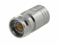
Adapters Between Series
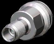
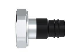
7-4 Go online for data sheets & assembly instructions. Visit www.radiall.com and enter the part number. SIMPLIFICATION IS OUR INNOVATION Interface A Interface B Part number 3D Series Gender Series Gender 4.1-9.5 Female 4.3-10 Male R191 598 007 4.3-10 Female 7-16 Male R191 592 007 Female R191 592 037 N Male R191 591 007 NEX10 Female R191 620 037 Male 4.1-9.5 Female R191 598 007 7-16 Female R191 592 017 Male R191 592 027 N Female R191 591 017 7-16 Female 4.3-10 Female R191 592 037 4.3-10 Male R191 592 017 N Female R191 723 000
Adapters Between Series


ADAPTERS
7-5 Go online for data sheets & assembly instructions. Visit www.radiall.com and enter the part number. SIMPLIFICATION IS OUR INNOVATION Interface A Interface B Part number 3D Series Gender Series Gender 7-16 Female N Male R191 720 000 Male 4.3-10 Female R191 592 007 4.3-10 Male R191 592 027 N Female R191 722 000 N Male R191 721 000 NEX10 Female R191 620 017 N Female 4.3-10 Male R191 591 017 7-16 Female R191 723 000 7-16 Male R191 722 000 NEX10 Male R191 620 007 NEX10 Male R191 630 007 NEX10 Female R191 620 027
ADAPTERS
Adapters Between Series
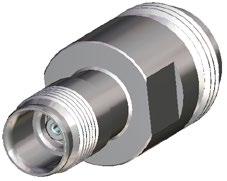
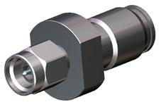
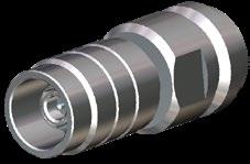
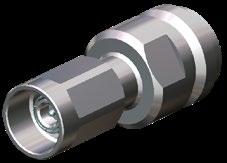
7-6 Go online for data sheets & assembly instructions. Visit www.radiall.com and enter the part number. SIMPLIFICATION IS OUR INNOVATION Interface A Interface B Part number 3D Series Gender Series Gender N Male 4.3-10 Female R191 591 007 7-16 Female R191 720 000 7-16 Male R191 721 000 NEX10 Female 4.3-10 Female R191 620 037 7-16 Male R191 620 017 N Female R191 620 027 SMA 3.5 Male R191 621 017 Male N Female R191 620 007 N Female R191 630 007 SMA 3.5 Female R191 621 007 SMA 3.5 Female NEX10 Male R191 621 007 Male NEX10 Female R191 621 017
Adapters in Series
7-16 SERIES
7-7 Go online for data sheets & assembly instructions. Visit www.radiall.com and enter the part number. SIMPLIFICATION IS OUR INNOVATION
Part number 3D Captive center contact Finish Note R185 703 000 Yes Silver + Copper Male - Male R185 705 000 Female - Female R185 707 000 Male - Female R185 710 000 Female - Female flange mount R185 730 020 Silver + BBR Female - Female
ADAPTERS
ADAPTERS
Adapters in Series
N SERIES
R161 703 000 Male - Male
R161 705 000 Female - Female
R161 715 000 Female - Female / Flange

R161 730 000 Female - Female / Bulkhead panel sealed

R161 753 000 Female - Female / Hermetic / Bulkhead
R161 771 000 Push-on Male / Female screwing
R161 791 500
male / female screwing
R161 791 530 Push-on Female / Male screwing
7-8 Go online for data sheets & assembly instructions. Visit www.radiall.com and enter the part number.
IS OUR INNOVATION
SIMPLIFICATION
3D Note
Part number
push-on
Adapters in Series 4.3-10
7-9 Go online for data sheets & assembly instructions. Visit www.radiall.com and enter the part number. SIMPLIFICATION IS OUR INNOVATION
Part number 3D Note R183 703 007 Male - Male R183 705 007 Female - Male
707 007 Male - Male
R183
ADAPTERS
RxF SERIES
SIMPLIFICATION IS OUR INNOVATON Visit www.radiall.com for more information SECTION 8
R2F / R4F
8-3 Go online for data sheets & assembly instructions. Visit www.radiall.com and enter the part number. SIMPLIFICATION IS OUR INNOVATION RXF Introduction 8-4 Characteristics 8-5 RXF product range ..................................................................................................... 8-6 to 8-10 Accessories and tools 8-11 SECTION 8 TABLE OF CONTENTS Contents
RXF
Introduction
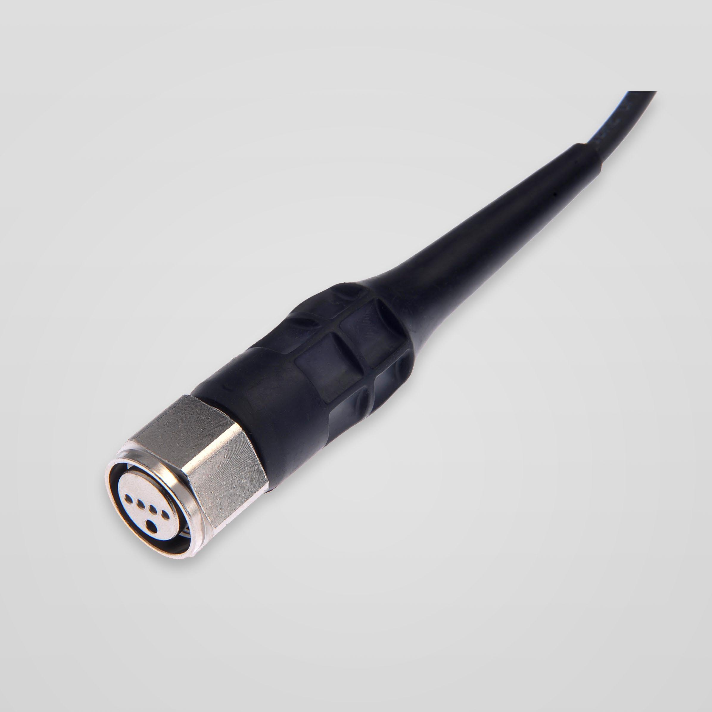
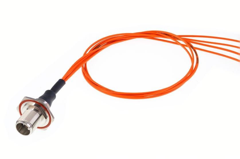
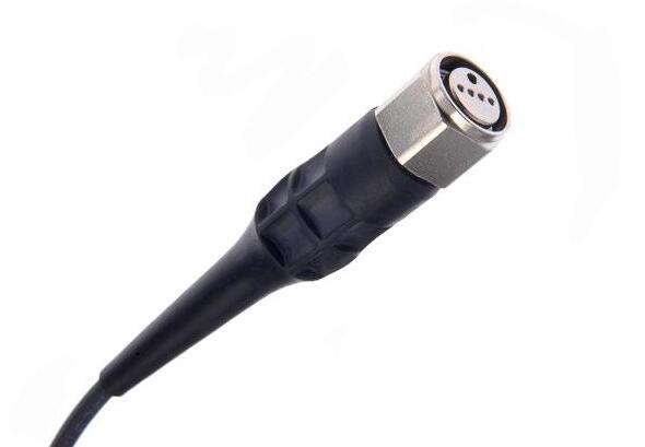
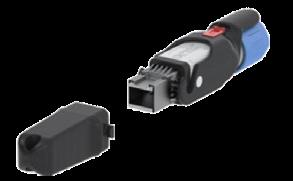
RXF: RADIALL OUTDOOR FIBER OPTIC CONNECTOR
Dedicated to outdoor optical connections, RXF is designed and manufactured by Radiall. RXF connectors are available with 2 and 4 channels, in MultiMode or SingleMode UPC versions.
RXF can be provided as a complete cable assembly or connector kit depending on customer needs. A quick-locking device with IP68 sealing and low loss insertion allows this connector to be used in severe outdoor connections and harsh environments.
APPLICATIONS
• Wireless communications
• Energy
• Transportation
• Monitoring display
International Standard Document Compliance
- IEC 61300 Fiber optic interconnecting devices and passive components
- Telcordia GR-326-CORE optical connectors and jumper assemblies
- IEC 60529 Degrees of protection provided by enclosures (IP code)
- EN 50125 Railway applications - environmental conditions for equipment
- MIL-PRF-39012 Standard N type mechanical interface
- RoHS compliant
Features and Benefits
• Robust connection
- Fully protected ceramic ferrules and alignment sleeves: no risk to damage the optical faces during mounting/dismounting operations
- Standard mechanical interface: N type screwing according to MIL-PRF-39012
- Use of standard optical ferrules 1.25mm
• Easy installation
- Qualified with other compatible outdoor fiber optic N type connectors
- Screwed locking mechanism: easy to install (U-19mm wrench/1 N.m torque)
- Fast and easy connection: one-hand blind mate coupling
• Suitable for harsh environments (adapted for outdoor use)
- Waterproof connection
- Dust proof
- Corrosion resistant
• High level of performance
- Full compliance to IEC 61300 standard
- High tensile strength
- EMI immunity
8-4 Go online for data sheets & assembly instructions. Visit www.radiall.com and enter the part number. SIMPLIFICATION IS OUR INNOVATION
Characteristics
OPTICAL CHARACTERISTICS
Insertion loss (IEC 61300-3-4)
Typical≤0.2 dB (max≤0.5 dB)
Return loss ≥50 dB
Insertion loss against a reference patchcord: IEC 61300-3-4 Method B
Return loss: IEC 61300-3-6
Note: The optical performance also depends on the fiber or cable qualities.
MECHANICAL CHARACTERISTICS
Mating endurance
Tensile resistance
Vibrations
Shocks
*Depending on cable type
ENVIRONMENTAL CHARACTERISTICS
Operating temperature range
Salt spray
Ingress protection class
MATERIALS
IEC 61300-2-2
500 mating cycles minimum
RXF Plug 800 N (with field cable)*
RXF Socket 30 N (with field cable)*
IEC 61300-2-1 Passed
IEC 61300-2-9 Passed
IEC 61300-2-22 -40°C/+85°C
IEC 61300-2-26 Passed
IEC 60529
IP 68 (with screwed cap or when mated)
Housing
8-5 Go online for data sheets & assembly instructions. Visit www.radiall.com and enter the part number. SIMPLIFICATION IS OUR INNOVATION
RXF
Brass
Nickel
Plating
RXF PLUG KITS

8-6 Go online for data sheets & assembly instructions. Visit www.radiall.com and enter the part number.
IS OUR INNOVATION
SIMPLIFICATION
RXF Product Range
Fig. 1
Part number Fiber type Fig. Dimensions (mm) Channels RXF2 130 500 Multi 1 5-5.6 2 RXF2 130 600 6 RXF2 130 700 7 RXF2 131 500 Single 5-5.6 RXF2 131 510 5-5.6 RXF2 131 600 6 RXF2 131 700 7 RXF4 130 500 Multi 2 5-5.6 4 RXF4 130 700 7 RXF4 131 500 Single 5-5.6
Fig. 2
RXF
RXF Product Range
RXF SOCKETS
8-7 Go online for data sheets & assembly instructions. Visit www.radiall.com and enter the part number. SIMPLIFICATION IS OUR INNOVATION
Fig. 1
Part number Fiber type Fig. Dimensions (mm) Channels RXF2 330 500 Multi mode 2 5-5.6 2 RXF2 331 500 Single mode
430 200 Multi mode 3 25.4 x 25.4 RXF2 431 200 Single mode RXF4 230 200 Multi mode 1 30 on flats 4 RXF4 231 200 Single mode RXF4 330 500 Multi mode 2 5-5.6 RXF4 330 700 Multi mode 7 RXF4 331 500 Single mode 5-5.6 RXF4 430 200 Multi mode 3 25.4 x 25.4 RXF4 431 200 Single mode
Fig. 2
RXF2
RXF
Fig. 3
RXF
RXF Product Range
RXF PLUG KITS
Radiall can accommodate different types of cables (simplex or field cables) and various diameters. The cable assemblies will be customized to fit with particular appliction requirements (specific labeling, length, etc.) and will be tested before shipment. Radiall's assembly plants have mass production capacity and can adapt to low and high volume demands.
DEFINE YOUR CABLE ASSEMBLIES:
1 - Number of channels: R2F or R4F
2 - Connector end 1 + protective cap
3 - Connector end 2 + protective cap
4 - Fiber type and cable type
5 - Length
SELECT
A
CABLE ASSEMBLY AMONG STANDARD PART NUMBERS:
Radiall designs, manufacturers and supplies standard outdoor cable assemblies. A standard configuration combines standard fiber optic connectors and cables with standard length and tolerances. Standard outdoor cable assemblies are catalog items with short lead times due to the direct availability of the components.
Note: Other lengths are available upon request.
Note: Other lengths are available upon request.
8-8 Go online for data sheets & assembly instructions. Visit www.radiall.com and enter the part number. SIMPLIFICATION IS OUR INNOVATION
R2F Socket Square Flange to LC Duplex – Indoor Simplex Cable Ø2 mm
Fiber type Part number Length SM 9/125 µm G652 F760 855 220 L=1 m MM 50/125 µm OM2 F760 858 220 L=1 m Fiber type Part number Length SM 9/125 µm G652 F760 855 240 L=1 m MM 50/125 µm OM2 F760 858 240 L=1 m
R4F Socket Hexagonal to 2 x LC Duplex – Indoor Simplex Cable Ø2 mm
RXF Product Range
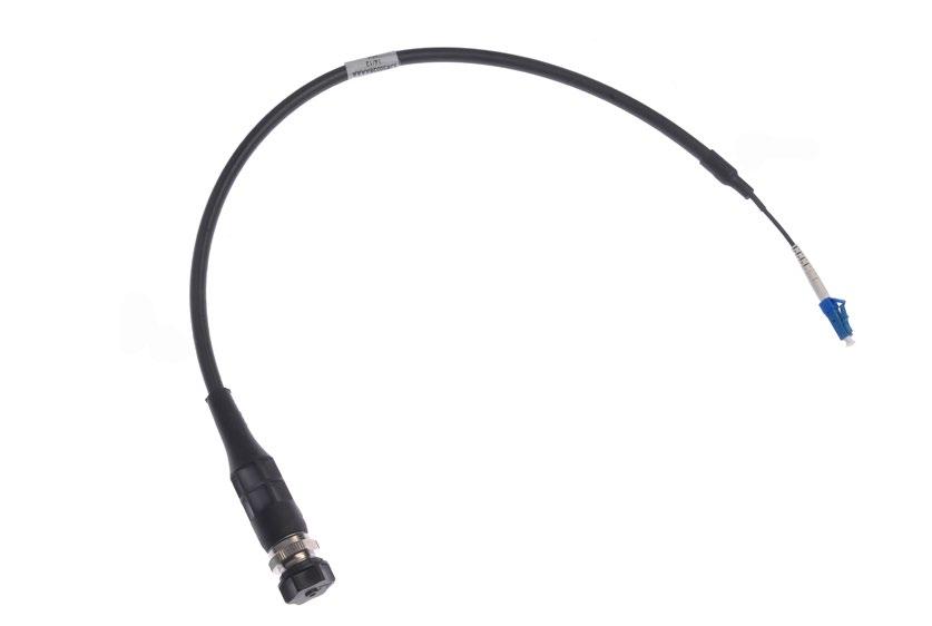
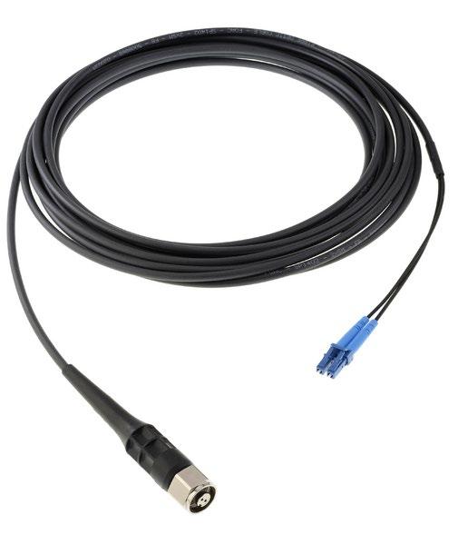
R2F Plug to LC Duplex – Outdoor Field Cable Ø5 mm Fiber
SM 9/125 µm G652 F760 855 620-XX
MM 50/125 µm OM2 F760 858 620-XX
(*): replace “XX” by the length in meters
Standard length: 5 m and 50 m
Ex: F760 855 620-05 for 5 m
R2F Plug to R2F Plug – Outdoor Field Cable Ø5 mm
SM 9/125 µm G652
885 620-XX
MM 50/125 µm OM2 F760 888 620-XX
(*): Replace “XX” by the length in meters
Standard length: 5 m and 50 m
Ex: F760 885 620-05 for 5 m
8-9 Go online for data sheets & assembly instructions. Visit www.radiall.com and enter the part number. SIMPLIFICATION IS OUR INNOVATION
RXF
type Part number (*)
Fiber type Part number (*)
F760
RXF Product Range RXF
R4F Plug to 2 x LC Duplex – Outdoor Field Cable Ø5 mm
SM 9/125 µm G652 F760 855 640-XX MM 50/125 µm OM2
(*): Replace “XX” by the length in meters
Standard length: 5 m and 50 m
Ex: F760 855 640-05 for 5 m
858 640-XX
R4F Plug to R4F Plug – Outdoor Field Cable Ø5 mm
50/125 µm OM2
(*): Replace “XX” by the length in meters
Standard length: 5 m and 50 m
Ex: F760 885 640-05 for 5 m
885 640-XX
888 640-XX
8-10 Go online for data sheets & assembly instructions. Visit www.radiall.com and enter the part number. SIMPLIFICATION IS OUR INNOVATION
type Part number
Fiber
(*)
Fiber type Part number (*)
F760
F760
F760
SM 9/125 µm G652
MM

8-11 Go online for data sheets & assembly instructions. Visit www.radiall.com and enter the part number. SIMPLIFICATION IS OUR INNOVATION
Accessories and Tools RXF
Fig. 1
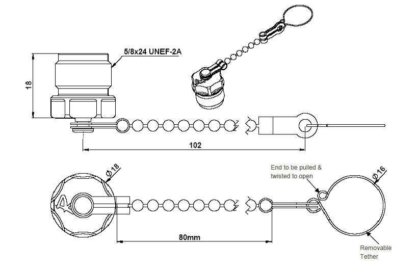
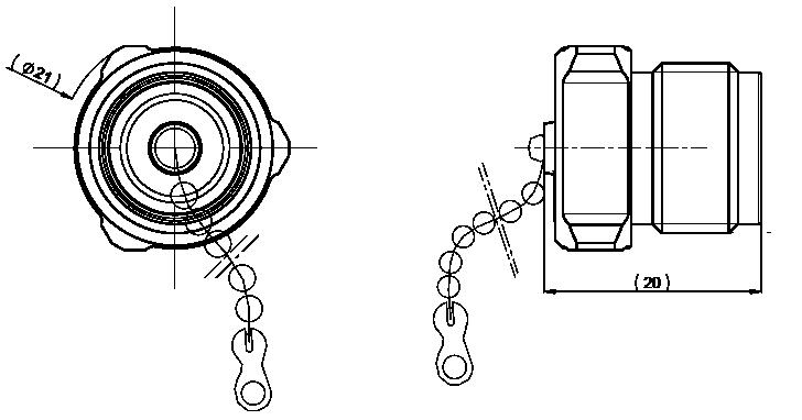
Part number Description Fig. R161 841 010 Metal female protective cap with chain 1 R161 853 000 Metal male protective cap with chain 2 RXF0 129 500 Plug plastic cap with chain and removable tether 3 243 25 810 Plug plastic cap with chain 4 240 92 675 Vinyl plastic cap 5
Fig. 4
Fig.
2
Fig.
3
Fig. 5
Accessories and Tools
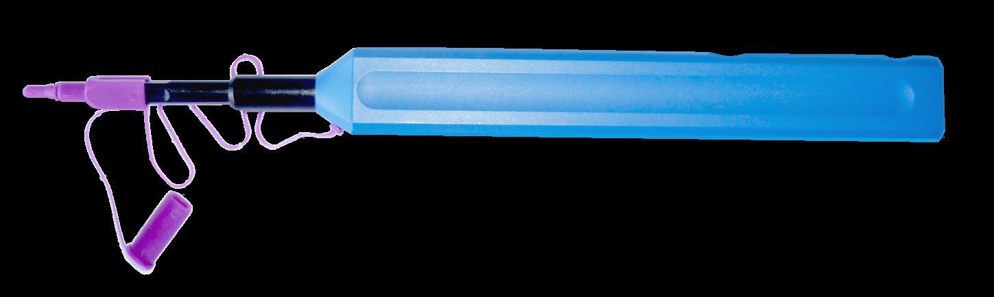
The mechanical cleaning tool to clean RXF optical end-faces. The tool uses a dry cleaning strand to gently sweep and lift away dust and residue from the connector end-face.
8-12 Go online for data sheets & assembly instructions. Visit www.radiall.com and enter the part number. SIMPLIFICATION IS OUR INNOVATION
RXF
Part number Description Packaging F780 906 001 RXF cleaning tool Unitary
OCTIS
SIMPLIFICATION IS OUR INNOVATON Visit www.radiall.com for more information SECTION 9
™ SERIES
9-3 Go online for data sheets & assembly instructions. Visit www.radiall.com and enter the part number. SIMPLIFICATION IS OUR INNOVATION OCTIS Introduction 9-4 Characteristics 9-5 SFP / SFP+ ...................................................................................................................... 9-6 RJ45 9-7 Power 9-8 Signal 9-9 Combo 9-9 Universal 9-10 Accessories and tools 9-11 SECTION 9 TABLE OF CONTENTS Contents
™ Introduction
OCTIS
Features and Benefits
• Suitable for harsh environments
- Waterproof connection
- Dust proof
- Corrosion resistant
- Extreme temperatures withstanding
• Quick and easy installation
- Blind mating
- Visual coding
- Physical coding
• Versatile solution
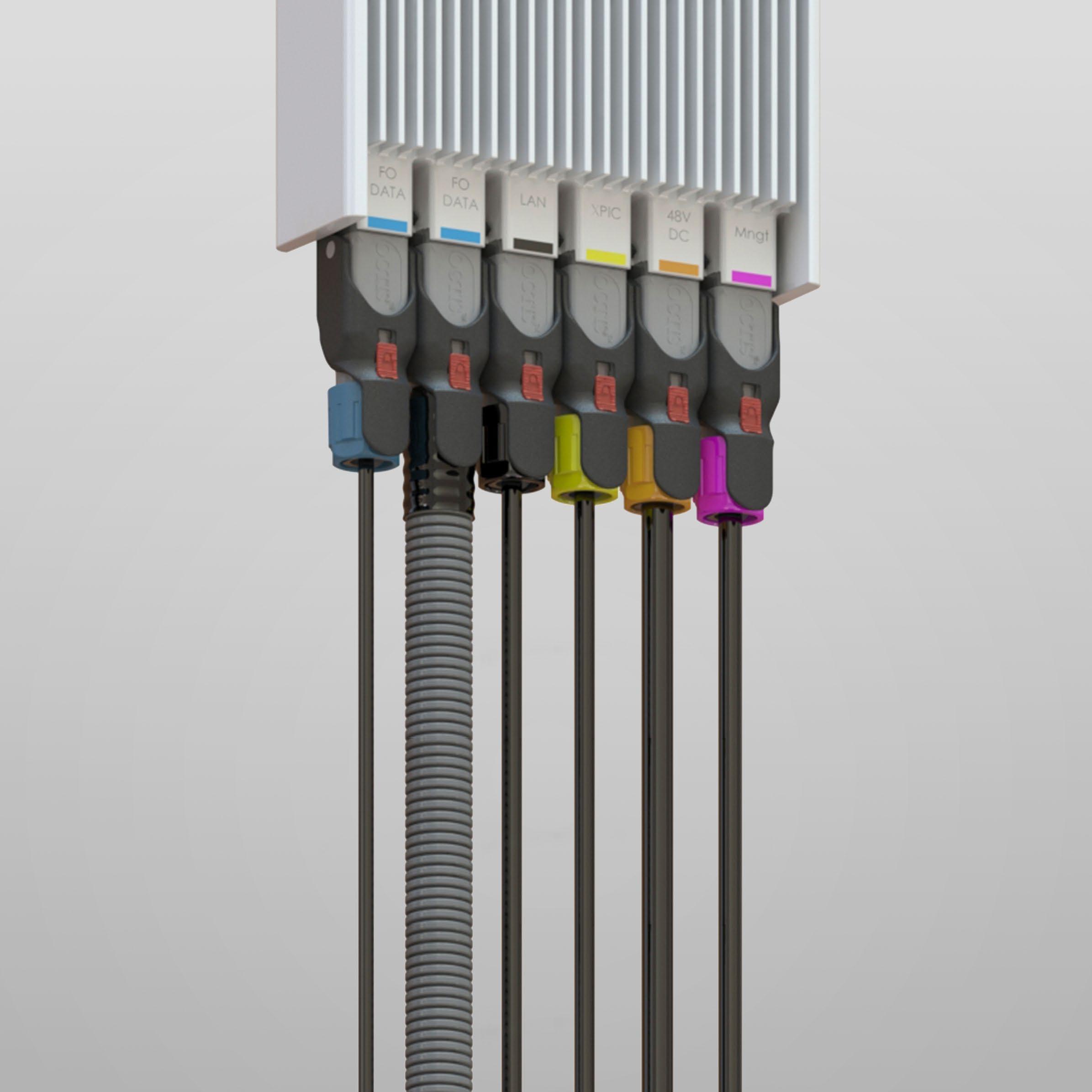
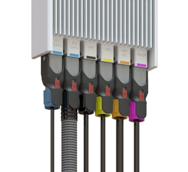
OCTIS™ is a compact multi-standard solution designed for outdoor wireless applications where reliability and high data transmission are required. OCTIS™ provides a robust I/O solution that can operate in harsh environments.
APPLICATIONS
• Wireless communications
• Industry
• Energy
- Cable tensile and side load
- EMI shielding
- Lightning resistant
- Field assembly of the plugs on the cable
- Turn-key design of the equipment front panel to integrate the receptacle
The complete OCTIS™ range offers a variety of interface solutions including:
- SFP
- RJ45 for tab up socket
- RJ45 for tab down socket
- Power DC with 2 contacts + cable shielding
- Power AC with 3 contacts
- Mulipin signal from 8 to 12 pins, compatible with Ethernet Cat5e
- Combo with Power DC and signal multipin in one single connection
- Universal: for LC DUplex, SC, USB, etc.
9-4 Go online for data sheets & assembly instructions. Visit www.radiall.com and enter the part number. SIMPLIFICATION IS OUR INNOVATION
Test / Characteristics
MECHANICAL
CHARACTERISTICS
Coupling mechanism
Durability (mating cycles) (IEC 61300-2-2)
Tensile load on cable (IEC 61300-2-4)
Values / Remarks SFP RJ45 Power Signal Combo
Lever + locking button
100 min (50 before and 50 after thermal cycles)
150 - 200 N depending on cable
Side load on cable (GR950) 50 N min
Cable size
Vibration (IEC 61300-2-1)
Low level vibration (IEC 61300-2-1)
5 to 11 mm jacket diameter (with proper grommet size)
GR-950(12/2010), GR3108(12/2008)
GR-950(12/2010), GR3108(12/2008)
Packaged equipment shock (GR-950) Fall from 1 m
ENVIRONMENTAL CHARACTERISTICS
Temperature range
Thermal aging (GR950)
-40 ... +85°C
90°C during 720h then 24 hours at 23°C
Thermal cycling (GR950) 120 cycles equivalent to 30 days
Corrosion
Ozone exposure (GR-950, ASTM D 518, ASTM D 1149)
720 h salt mist + SO2 (ISO21207)
Rubber components : 40°C during 70h; Ozone 50 mPa
Ingress protection IP67 - IP68 (when mated)
RoHS compliant
Flammability
UL94-V0
UV resistance (GR950, ASTM G154) UVB 1000 hours
Fungus resistance (GR-950, ASTM G 21)
ELECTRICAL CHARACTERISTICS
Contact resistance
Working voltage
Insulation resistance (EIA 364-21)
Dielectric Withstanding Voltage (EIA 364-20)
Current rating
Cross talk
Impedance of pairs
IL
Incubation 28 days, 29°C,96%RH
IEC 60512, Test 2a
≤4 mΩ @ 20A DC (EIA 364-06)
300 V AC (r.m.s)
Refer to Cable assembly characteristics
Refer to Cable assembly characteristics
55 mΩ Max (EIA 364-23B, 4 wire pethod)
5000 MΩ min
500V AC during 60 s @ 1 atm 1000V AC during 60 s
16A with AWG16 wire (7xAWG24)
20A with AWG14 wire (7xAWG22) 1,5 A per pair
Pair to pair
@20MHz < -60dB
All pairs to one victim @ 20MHz < -54dB (powersum)
100Ω +/- 10% @ 30 MHz
< 0.1 dB @ 30MHz
RL < -37 dB @ 20MHz
EMI shielding
Full EMI shielding of the panel cavity
Same as Power and Signal
EMI shielding by reduction of the panel cavity
Grounding Direct connection of cable braiding to the panel
Lightning (IEC 62305-1)
Conducted immunity Surge (GR-1089-CORE – R4-25) (IEC 61000-4-5)"
> 5KA with wave form 10/350 µs on cable braiding
> 1KA with wave form 10/350 µs on individual wires
> 5KA with wave form 10/350 µs on all wires together
> 2,2 KA with wave form 8/20 µs on individual wires
> 6KV on individual wires
> 6KV on all wires together
Wave form 1,2/50 µs – open circuit /8/20 µs – short circuit 2 ohm
9-5 Go online for data sheets & assembly instructions. Visit www.radiall.com and enter the part number. SIMPLIFICATION IS OUR INNOVATION
Characteristics OCTIS ™

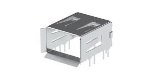
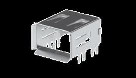
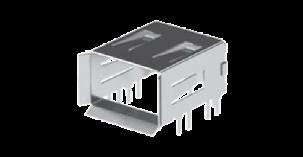
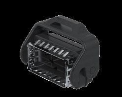
9-6 Go online for data sheets & assembly instructions. Visit www.radiall.com and enter the part number. SIMPLIFICATION IS OUR INNOVATION SFP / SFP+ Part number Description Fig. Packaging OCTI 117 500 SFP/SFP+ Plug kit 1 Bag OCTI 107 500 SFP/SFP+ Screw-on receptacle 2 Tray OCTI 140 500 SFP cage, Pin-In-Paste 3 OCTI 140 505 Tape & Reel OCTI 140 550 "SFP cage, Press fit 4 Tray
™ Fig. 1
2
OCTIS
Fig.
3
Fig.
Fig.
4
* To be used with specific board socket, contact us for more information.
9-7 Go online for data sheets & assembly instructions. Visit www.radiall.com and enter the part number. SIMPLIFICATION IS OUR INNOVATION
RJ45 Part number Description Fig. OCTI 217 500 RJ45 Tab Up Plug kit, coding left* 1 OCTI 207 500 Receptacle kit RJ45 coding left 2 OCTI 217 505 RJ45 Tab Up Plug kit, coding right* 1 OCTI 207 505 Receptacle kit RJ45 coding right 3 OCTI 217 550 RJ45 Tab Down Plug kit* 1 OCTI 207 550 RJ45 Tab Down Receptacle 4
Fig. 4
Fig. 1
Fig. 2
Fig. 3
9-8 Go online for data sheets & assembly instructions. Visit www.radiall.com and enter the part number. SIMPLIFICATION IS OUR INNOVATION Power Part number Description Contacts Fig. OCTI 317 500 Power Plug kit, crimp contacts 2 power contacts + cable grounding 1 OCTI 327 500 Power Plug kit for field assembly OCTI 360 500 Power board socket 2 OCTI 337 500 Power Plug kit, crimp contacts 3 power contacts 1 OCTI 337 550 Power Plug kit for field assembly OCTI 363 500 Power board socket 3 Fig. 1 Fig. 2 Fig. 3
™
OCTIS


9-9 Go online for data sheets & assembly instructions. Visit www.radiall.com and enter the part number. SIMPLIFICATION IS OUR INNOVATION OCTIS ™ Signal Part number Description Contacts Fig. OCTI 417 500 Signal Plug kit 8 signal contacts + cable grounding 1 OCTI 407 500 Signal receptacle 3 OCTI 460 500 Signal board socket 2
1
Fig.
Fig.
2
3 Combo Part number Description Contacts Fig. OCTI 517 500 Combo Plug kit 2 Power contacts + 8 signal contacts + cable grounding 1 OCTI 560 500 Combo board socket 3 OCTI 507 500 Combo receptacle 2
Fig.
1
Fig.
2
Fig.
3
Fig.
OCTIS
OCTI 127 500 Plug kit for panel adaptator 1 OCTI 907 500 Universal screw-on receptacle** 2

** Suited for any cable assembly with interface fitting through a 15 mm diameter hole.
9-10 Go online for data sheets & assembly instructions. Visit www.radiall.com and enter the part number. SIMPLIFICATION IS OUR INNOVATION
™ Universal
Fig.
Part number Description
Fig. 2
Fig. 1
and
9-11 Go online for data sheets & assembly instructions. Visit www.radiall.com and enter the part number. SIMPLIFICATION IS OUR INNOVATION
Accessories
Tools OCTIS ™
Fig. 1
Fig.
957 500 EMI + IP67 receptacle cap1
Fig. 2
Part number Description
OCTI
957 550 IP 67 receptacle cap2
955 500 Dust cap 3
W57 500 Universal cap 4
OCTI
OCTI
OCTI
Fig. 3
Fig. 4

HEP2R PLATING
SIMPLIFICATION IS OUR INNOVATON Visit www.radiall.com for more information SECTION 10
10-3 Go online for data sheets & assembly instructions. Visit www.radiall.com and enter the part number. SIMPLIFICATION IS OUR INNOVATION HEP2R Introduction
SECTION 10 TABLE OF CONTENTS Contents
10-4 to 10-5
Introduction
Overview
Today, telecommunication operators are installing more equipment in high humidity, hot temperature conditions which ultimately subjects the products to corrosive gases from industrial or traffic environments.
To meet the needs of these harsh environments a new solution is required. This solution should enable products to withstand neutral salt spray for 720 hours and ISO 21207 – a test procedure simulating severe industrial or traffic environment.
In the past, BBR or white bronze plating was typically used but has proven to result in unsatisfactory corrosion resistance levels. To improve the performance of products, post-treatment was applied on BBR or silver+BBR plated products. Although this showed some improvement, post-treatment is not considered a long term, reliable solution and can provide additional risks over the product life cycle.
ISO
Corresponding test duration vs Years in specified environment
Source: International Standard ISO 21207 (2004)
10-4 Go online for data sheets & assembly instructions. Visit www.radiall.com and enter the part number. SIMPLIFICATION IS OUR INNOVATION
21207 METHOD B
HEP 2 R
Week 2 Weeks 3 Weeks 5 Weeks 3 Years 8 Years 14 Years 27 Years Life Cycle Years Weeks
1
Initial State
After NSS 720Hrs After ISO 21207 5 Cycles

HEP²R provides similar galvanic cells to bronze alloy surface treatment, which makes this plating solution ideal for commonly used materials and alloy in coaxial connectors.
Since 1977, Radiall has been dedicated to developing plating solutions for industrial applications. Over the years, Radiall has studied several plating alloys to meet the stringent requirements harsh environments produce.
HEP²R (Harsh Environment Protective Plating by Radiall) is a new plating solution that meets ASTM B 117 & ISO 21207 Method B 5 cycle testing.
Due to its unique benefits, HEP²R has received attention from the telecom industry and is the preferred plating solution to protect outdoor connectors in high corrosion environments for a long period. HEP²R is a cost effective plating solution suitable for outdoor connectors where maintaining the products appearance is critical.
To determine product performance and durability, products undergo ISO 21207 testing which simulates 27 years of exposure in severe traffic environment or industrial environment with salt spray contamination. Radiall’s HEP²R has successfully passed ISO 21207 testing and showed no corrosion and very little change in appearance.
APPLICATIONS
Based on its environmental performance, HEP²R plating is mainly dedicated for Telecom applications with a focus on 4.3-10 and 7/16 connectors. For use on other products exposed to salt spray contamination or corrosive gases, please consult us.
FEATURES & BENEFITS
• Very low intermodulation (-135 dBm on 4.3-10 connector)
• No change on VSWR compared to similar product plated with BBR
• High corrosion resistance (ASTM B 117 / TELCORDIA GR–487–CORE / ISO 21207 Method B 5 Cycles)
• Similar galvanic cell level compared to BBR plating
• High hardness
• Anti-seize properties
• Not subject to whiskers
• Non magnetic plating
• Good solderability
• Hypoallergenic plating
• RoHs and REACH compliant
• Cyanides free
10-5 Go online for data sheets & assembly instructions. Visit www.radiall.com and enter the part number. SIMPLIFICATION IS OUR INNOVATION
HEP 2 R
Introduction
Part Number Index
SIMPLIFICATION IS OUR INNOVATON Visit www.radiall.com for more information SECTION 11 INDEX
N SERIES
R161 050 300 4-8
R161 051 000 4-8
R161 052 000 4-8
R161 053 000 4-8
R161 054 000 4-8
R161 072 000 ............ 4-8
R161 075 030 ............ 4-8
R161 082 120 4-8
R161 082 200 4-8
R161 088 180 4-8
R161 182 080 4-9
R161 152 107 4-9
R161 183 310 4-9
R161 184 080 4-9
R161 188 200 ............ 4-9
R161 226 020 .......... 4-10
R161 227 000 4-10
R161 277 300 4-10
R161 278 000 4-10
R161 323 000 4-12
R161 329 130 4-12
R161 329 140 4-12
R161 331 400 4-12
R161 335 200 .......... 4-12
R161 336 000 .......... 4-12
R161 336 200 4-12
R161 337 200 4-12
R161 404 C01 4-15
R161 404 C02 4-15
R161 404 C03 4-15
R161 410 000 4-13
R161A 410 000 4-13
R161 410 130 .......... 4-13
R161 418 000 .......... 4-13
R161 461 000 4-13
R161 404 000 4-14
R161A 404 000 4-14
R161 404 137 4-14
R161 416 130 4-14
R161 419 020 4-14
R161 419 300 4-14
R161 438 200 4-14
R161 441 000 .......... 4-12
R161 441 400 4-14
R161 570 000 .......... 4-16
R161 606 000 4-16
R161 625 000 .......... 4-16
R161 653 000 4-15
R161 703 000 7-8
R161 705 000 7-8
R161 715 000 7-8
R161 730 000 7-8
R161 753 000 7-8
R161 771 000 7-8
R161 791 500 7-8
R161 791 530 7-8
R161 804 000 4-17
R161 805 410 4-17
R161 841 000 4-17
R161 844 000 4-17
R161 853 000 4-17
R161 862 000 4-17
4.1-9.5 SERIES
R170 031 007 3-6
R170 031 107 3-6
R170 031 207 3-6
R170 152 107 3-6
R170 413 127 3-6
NEX10 SERIES
R180 052 007 1-6
R180 052 017 1-6
R180 060 007 1-6
R180 060 017 1-6
R180 252 007 1-7
R180 300 007 1-6
R180 301 007 ............ 1-6
R180 415 007 1-7
R180 540 007 ............ 1-7
R180 805 007 1-7
R180 805 010 ............ 1-7
4.3-10 SERIES
R183 030 007 2-6
R183 030 017 2-6
R183 031 007 2-6
R183 031 017 2-6
R183 032 007 2-6
R183 052 007 ............ 2-6
R183 165 007 2-7
R183 197 007 ............ 2-7
R183 252 007 2-7
R183 405 067 ............ 2-7
R183 703 007 7-9
R183 705 007 7-9
R183 707 007 7-9
R183 804 020 2-8
7-16 SERIES
R185 054 020 5-8
R185 077 010 5-8
R185 083 310 5-8
R185 085 007 5-8
R185 215 200 5-8
R185 216 200 5-8
R185 217 200 ............ 5-8
R185 252 000 5-9
R185 314 100 ............ 5-9
R185 320 020 5-9
R185 403 490 .......... 5-10
R185 403 547 5-10
R185 404 200 5-10
R185 405 200 5-10
R185 406 090 5-10
R185 703 000 7-7
R185 705 000 7-7
R185 707 000 7-7
R185 710 000 7-7
R185 730 020 7-7
RECEPTACLES
R187 403 010 5-11
R187 130 000 .......... 5-11
R187 403 000 5-11
R187 403 100 5-11
R187 406 000 5-11
R187 406 100 5-11
R187 413 000 5-11
R187 413 100 5-11
R187 416 000 .......... 5-11
R187 416 100 .......... 5-11
ADAPTER SERIES
R191 591 007 7-4
R191 591 017 ............ 7-5
R191 592 007 ............ 7-5
R191 592 017 7-4
R191 592 027 7-5
R191 592 037 7-4
R191 598 007 7-4
R191 620 007 7-5
R191 620 017 7-5
R191 620 027 7-5
R191 620 037 ............ 7-4
R191 621 007 ............ 7-6
R191 621 017 7-6
R191 630 007 7-5
R191 720 000 7-5
R191 721 000 7-5
R191 722 000 7-5
R191 723 000 7-5
RxF ACCESSORIES
243 25 810 8-11
240 92 675 8-11
TOOLS
R282 202 000 4-17
R282 303 050 1-7
R282 303 240 2-9
R282 303 500 4-17
11-3 SIMPLIFICATION IS OUR INNOVATION Go online for data sheets & assembly instructions. Visit www.radiall.com and enter the part number.
INDEX
Radiall Part Numbers
INDEX
Radiall Part Numbers
JUMPER SERIES
R296 702 807 xxx 6-5
R296 702 808 xxx 6-5
R296 702 809 xxx 6-5
R296 702 810 xxx 6-5
R296 702 811 xxx 6-5
R296 702 812 xxx 6-5
R296 702 813 xxx 6-5
R296 702 814 xxx 6-5
R296 702 815 xxx 6-5
R296 702 816 xxx 6-5
R296 702 817 xxx 6-5
R296 702 818 xxx 6-5
4.3-10 SERIES
R404 1D1 121 2-9
R404 758 000 2-10
R404 759 000 2-10
R404 1D2 000 2-9
R404 1D2 121 2-9
R404 1D5 000 2-9
TERMINATIONS & ATTENUATORS
R404 131 000 .......... 4-19
R404 131 120 .......... 4-19
R404 132 000 .......... 4-19
R404 170 111 .......... 5-13
R404 507 000 4-19
R404 557 000 4-19
R404 750 000 4-19
R404 751 000 4-19
R404 758 000 2-10
R404 759 000 2-10
R404 756 000 5-13
R412 700 000 4-20
R412 700 124 4-20
R412 806 000 5-14
R415 6XX 000 2-10
R415 703 000 4-21
R417 303 110 4-21
R417 303 130 4-21
R420 303 110 5-14
R494 175 111 5-13
R494 564 000 5-13
CABLE
F760 855 220 8-8
F760 855 240 8-8
F760 855 620-XX 8-9
F760 855 640-XX 8-10
F760 858 220 8-8
F760 858 240 8-8
F760 858 620-XX 8-9
F760 858 640-XX 8-10
F760 885 620-XX 8-9
F760 885 640-XX 8-10
F760 888 620-XX 8-9
F760 888 640-XX 8-10
TOOLS (RxF)
F780 906 001 8-12
F760 888 640-XX 8-10
RxF
RXF0 129 500 8-11
RXF2 130 500 8-6
RXF2 130 600............ 8-6
RXF2 130 700............ 8-6
RXF2 131 500............ 8-6
RXF2 131 510............ 8-6
RXF2 131 600............ 8-6
RXF2 131 700............ 8-6
RXF4 130 500 8-6
RXF4 130 700 8-6
RXF4 131 500 8-6
RXF2 330 500 8-7
RXF2 331 500 8-7
RXF2 430 200 8-7
RXF2 431 200 8-7
RXF4 230 200 8-7
RXF4 231 200 8-7
RXF4 330 500 8-7
RXF4 330 500 8-7
RXF4 331 500 8-7
RXF4 430 200 8-7
RXF4 431 200 8-7
OCTIS™ SERIES SFP
OCTI 107 500 9-6
OCTI 117 500 9-6
OCTI 140 500 9-6
OCTI 140 505 9-6
OCTI 140 550 9-6
RJ45
OCTI 207 500 9-7
OCTI 207 505 9-7
OCTI 207 550 9-7
OCTI 217 500 9-7
OCTI 217 505 9-7
OCTI 217 550 9-7
POWER
OCTI 317 500 9-8
OCTI 327 500 9-8
OCTI 337 500 9-8
OCTI 337 550 ............ 9-8
OCTI 360 500 ............ 9-8
OCTI 363 500 ............ 9-8
SIGNAL
OCTI 407 500 9-9
OCTI 417 500 9-9
OCTI 460 500 9-9
COMBO
OCTI 507 500 9-9
OCTI 517 500 9-9
OCTI 560 500 9-9
UNIVERSAL
OCTI 127 500 9-10
OCTI 907 500 9-10
ACCESSORIES
OCTI 955 500 9-11
OCTI 957 500 .......... 9-11
OCTI 957 550 .......... 9-11
OCTI W57 500 ......... 9-11
N
SERIES (CABLE GROUP)
4502-7041-010 4-12
4202-7041-009 4-12
4501-9543-009 4-12
11-4 SIMPLIFICATION IS OUR INNOVATION Go online for data sheets & assembly instructions. Visit www.radiall.com and enter the part number.
We advance the design and engineering process for innovators, ground-breakers and pioneers of technology. We reduce weight, improve durability and streamline installation to provide leading-edge connectors that drive product performance.
AREA OFFICES LOCAL CONTACTS
Radiall Finland PO Box 202, 90101, Oulu
FRANCE
GERMANY
ITALY
NETHERLANDS
SWEDEN
UNITED KINGDOM
Radiall SA 25 Rue Madeleine Vionnet, 93300, Aubervilliers
Radiall GmbH Carl-Zeiss-Straße 10, 63322, Rödermark
Radiall Elettronica S.R.L. Via Zambeletti 19, 20021, Baranzate Milano
Radiall Nederland BV Hogebrinkerweg 15b, 3871, KM Hoevelaken
Radiall AB Sollentunavägen 63, 191 40 Sollentuna
Radiall Ltd. Profile West, 950 Great West Rd., Brentford, Middlesex TW8 9ES
+358407522412
+33149353535
+49607491070
+39024885121
+31332534009
+4684443410
+441895425000
Shanghai Radiall Electronics Co., Ltd.
No.390, Yonghe Road, Shanghai, 200072
Radiall Electronics (Asia) Ltd. Room A, 16/F., Ford Glory Plaza, 37-39 Wing Hong Street, Cheung Sha Wan, Kowloon, Hong Kong
Radiall India Pvt. Ltd.
25D, Phase 2, Peenya Industrial Area, Bengaluru 560 058
Nihon Radiall K.K.
Sawada Building 8F, Shibuya-ku, Tokyo 150-0011
+862166523788
+85229593833
+98028395271
+0364274455
+496074910710
+390248843018
+31332534512
+441895425010
infofi@radiall.com info@radiall.com infode@radiall.com infoit@radiall.com infonl@radiall.com infose@radiall.com infouk@radiall.com
+14806829403 infousa@radiall.com FINLAND
Radiall USA, Inc. 8950 South 52nd Street, Ste. 401 Tempe, AZ 85284
GLOBAL
+14806829400
+862166521177
+85229592636
+918028397228
+0364274456
infosh@radiall.com
infohk@radiall.com
infoin@radiall.com
infojp@radiall.com
ADDRESS PHONE FAX EMAIL
PRESENCE EUROPE ASIA AMERICAS
USA & CANADA
CHINA
HONG KONG
www.radiall.com D1C165CE · 2018 EDITION
INDIA JAPAN