
B & MCS-R SERIES
INTRODUCTION
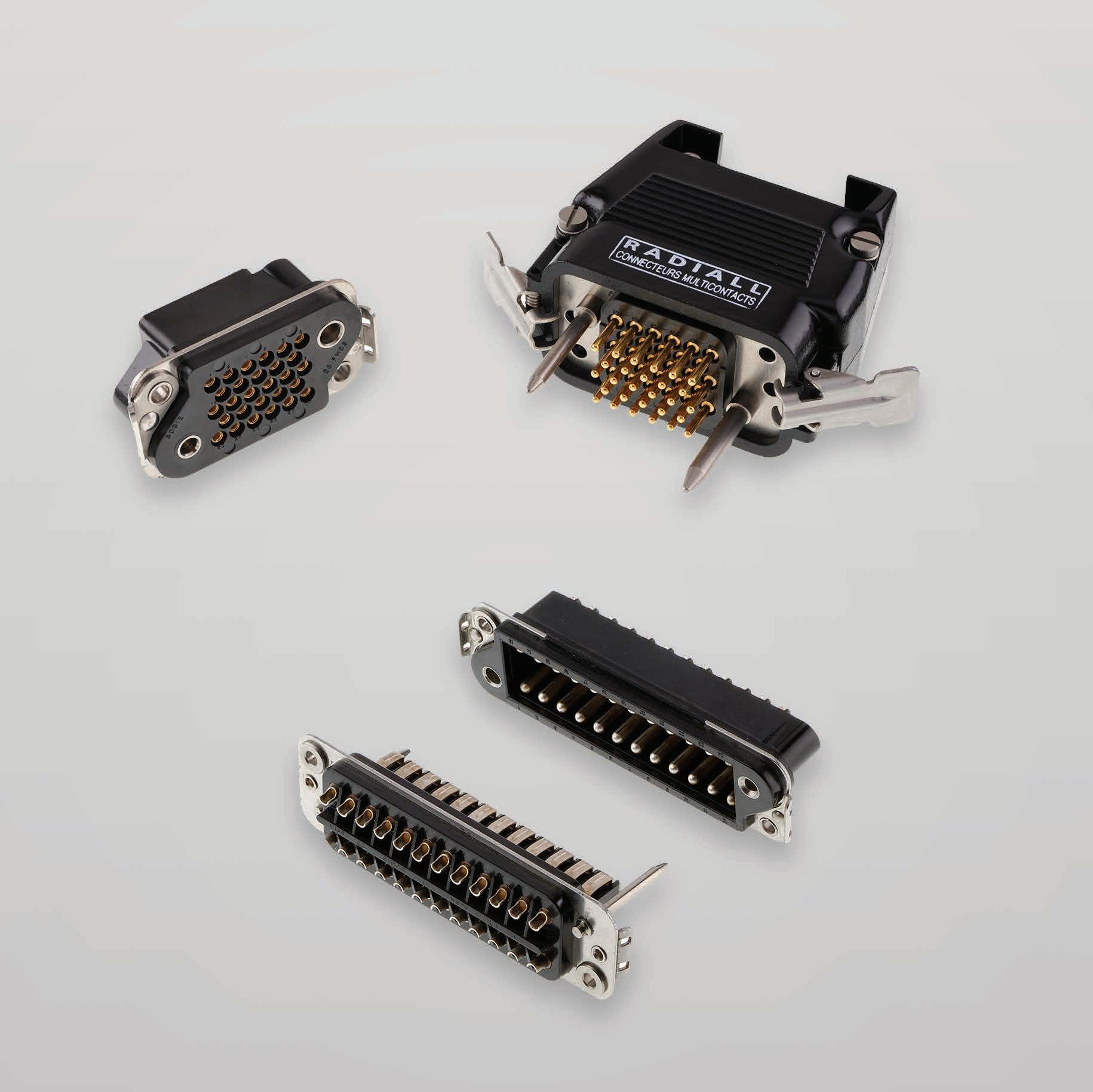
The B series connectors are of robust design with fixed solder pot contacts of 15 A current rating. They are available in four different contact arrangements. By their ruggedness, they are particularly suitable for rack and panel and cable to panel applications
APPLICATIONS
The series B connectors ensures complete safety for the following applications: Industries, transports, communications, power equipment and all specific civil and military electronic systems.
FEATURES
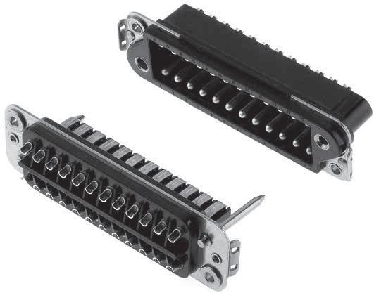
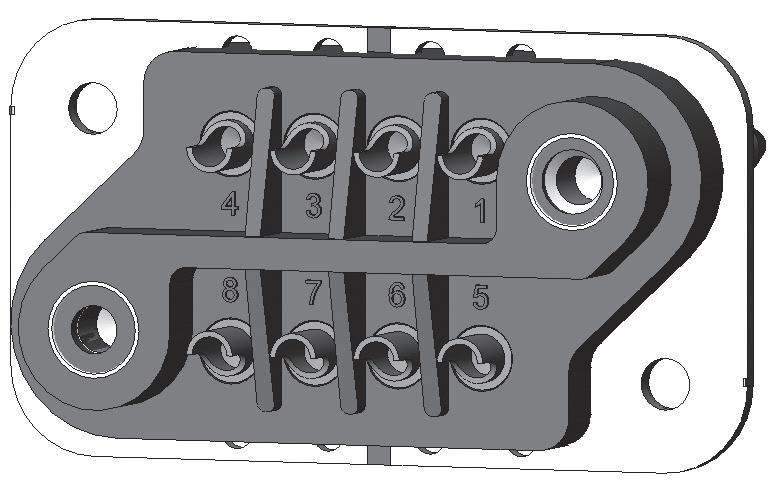
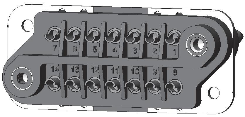
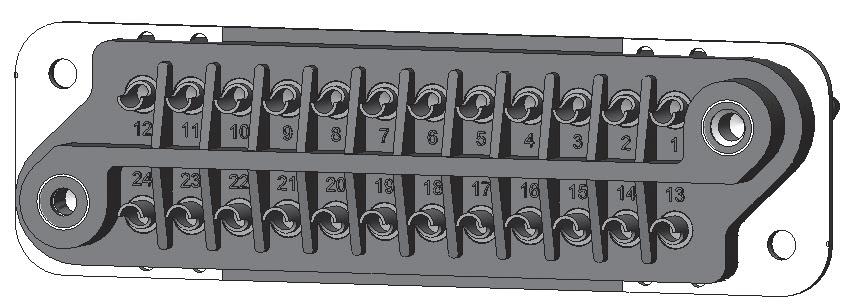
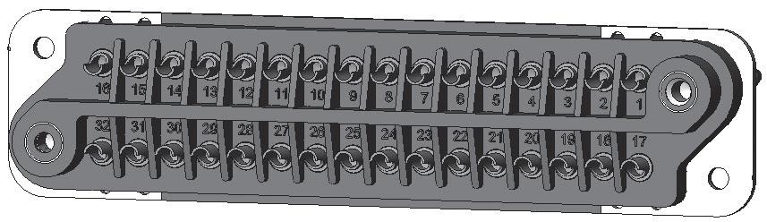
Plug and receptacle connectors are made of a thermoset insulator moulded onto a stainless steel fixing plate. Four contact arrangements are available, 8, 14, 24 and 32 contacts �
The receptacle box type connectors are fitted with round pin contacts. The plug connectors are fitted with spring blade contacts and two stainless steel guide pins of different diameter providing polarization and mating before the contacts to ensure correct alignment �
The pin contacts are in silver plated brass, the spring blade contacts are in silver plated bronze. The cambered configuration and elasticity procures a self wiping condition at each mating, ensuring high reliability.
The B series connector is only available with solder pot termination for gauge 16 wires Standard receptacle connectors are fitted with floating eyelets, which allows 0.75 mm radial float.
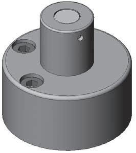
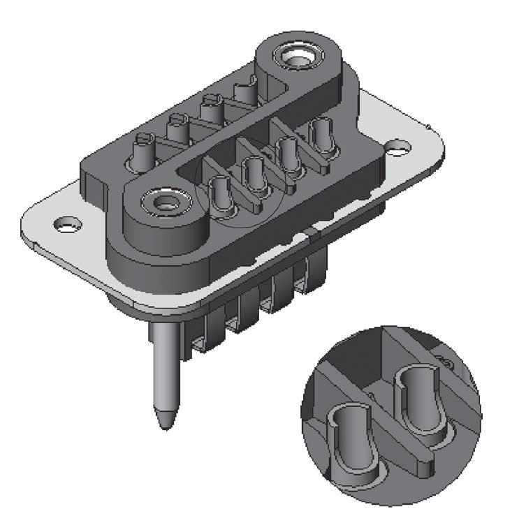
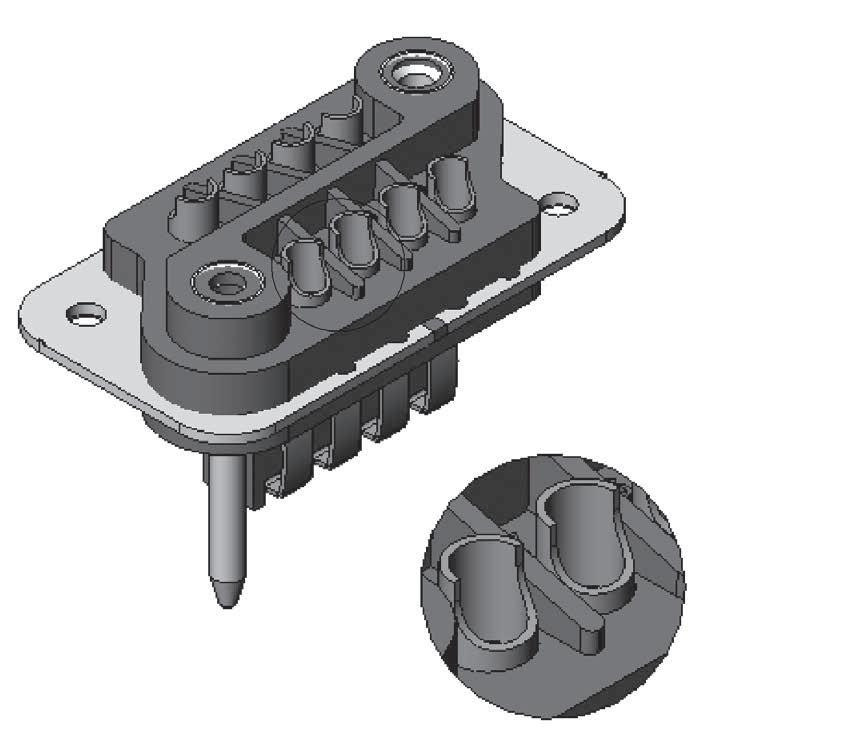
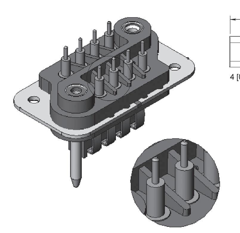
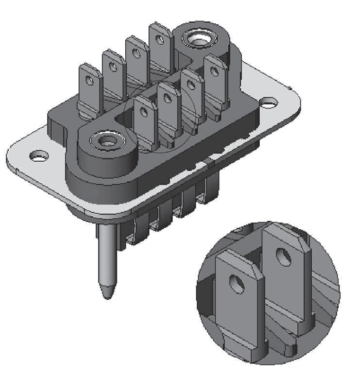
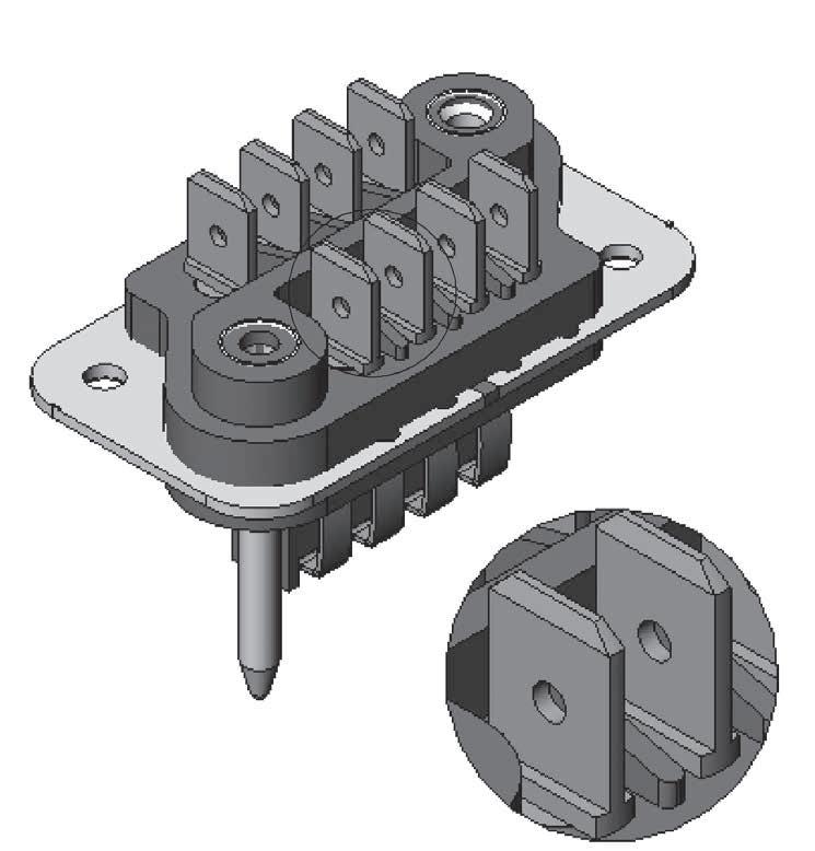
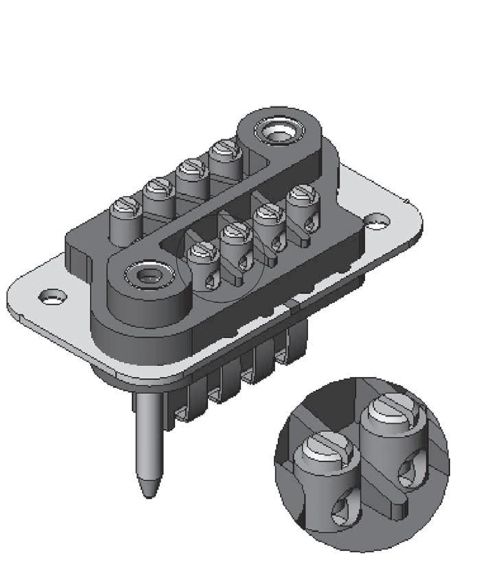
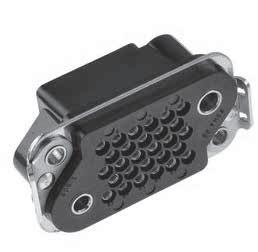
PRODUCT OVERVIEW
Detailed view of the various parts of this series connector
B Series
TECHNICAL
CHARACTERISTICS
ELECTRICAL
• Current Rating by Contact: 15 A
• Test Voltage:
- Between Contacts: > 1,500 Vrms
- Between Contacts and Earth: > 2,000 Vrms
• Insulation Resistance: > 5,000 MΩ
• Contact Resistance: < 10 mΩ
MECHANICAL & ENVIRONMENTAL
• Temperature Range: -55 °C (-131 °F) to +125 °C (+257 °F)
• Humidity: 21 Days
• Mating and Unmating: 500 Cycles
• Contact Retention: > 50 N
MATERIALS
MASSES G (OZ)
DESCRIPTION
Insulator Block
Pin Contacts (Male)
Spring Blade Contacts (Female)
MATERIAL/FINISH
Glass Filled Phenolic
Brass-Silver Plated
Bronze-Silver Plated
B Series
HOW TO ORDER CONNECTORS
The following indications are to help you out when ordering B connectors �
When a receptacle connector is ordered with the locking system, in place of the floating eyelets, brackets are fitted whilst the locking clips are always fitted on the backshell.
For backshell and accessories please refer to pages 9-18 to 9-19 for ordering
The plug connector is fitted with spring leaf contacts and the receptacle box type connector with pin contacts.
CONNECTOR PART NUMBER
BSERIES PREFIX
CONTACT ARRANGEMENT
08–14–24-32
PRODUCT TYPE
M: Plug connector
F: Receptacle connector [2]
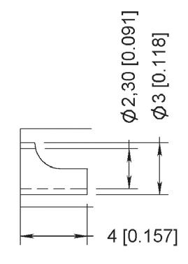
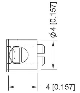
TERMINATION STYLE [1]
71: Ø 2 30 solder pot
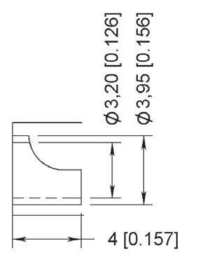
73: Ø 3 20 solder pot
74: PC Tail
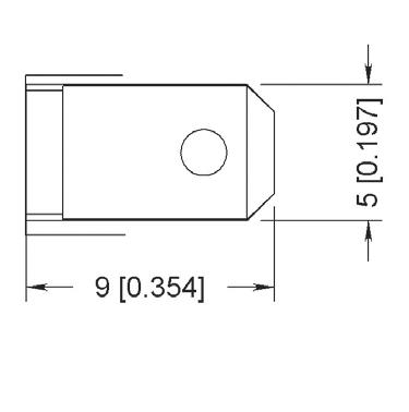
75: 5 mm terminal blade
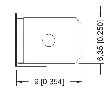
78: NFC 20120 terminal blade
80: Screw cup termination
MODIFICATION CODE
NV: Without locking
VP: Brackets for locking system receptacle only (see page 9-17 for details)
Notes
1. Please refer to page 9-6 for views of termination styles.
2. Receptacle connector: only the 71 termination style is available.
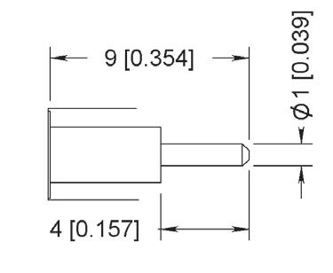
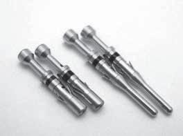
TERMINATION STYLES
Following are the different termination styles available in details
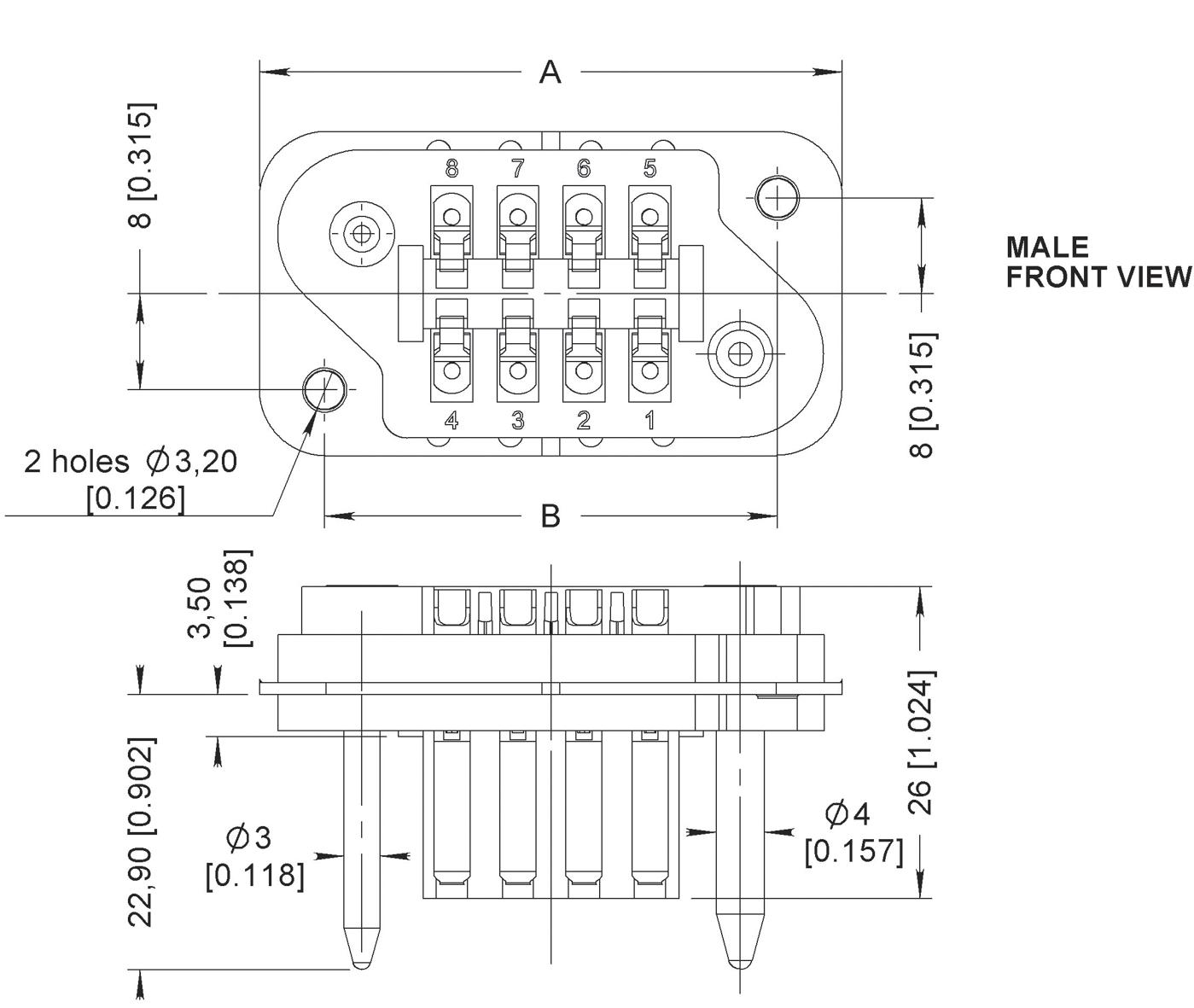
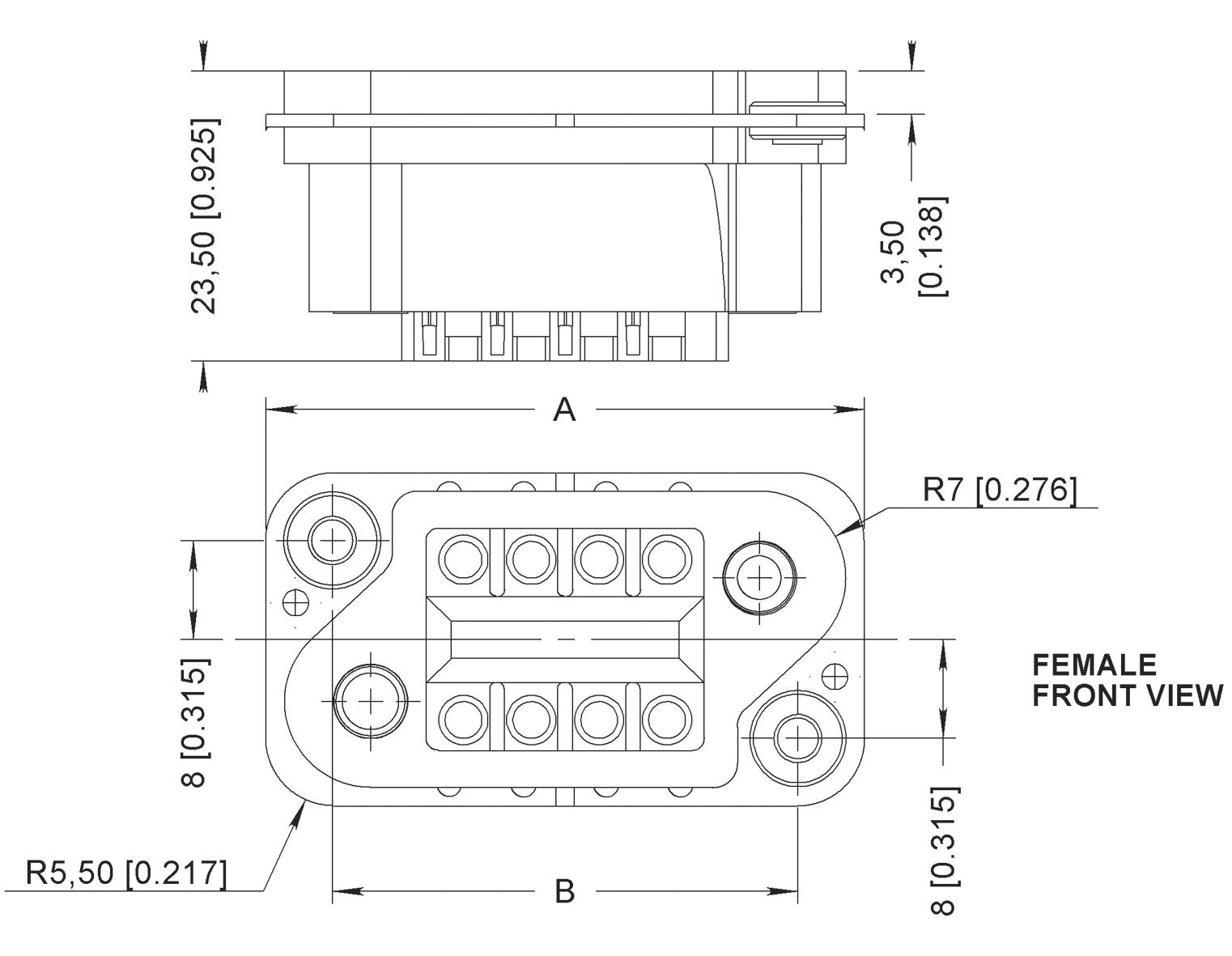
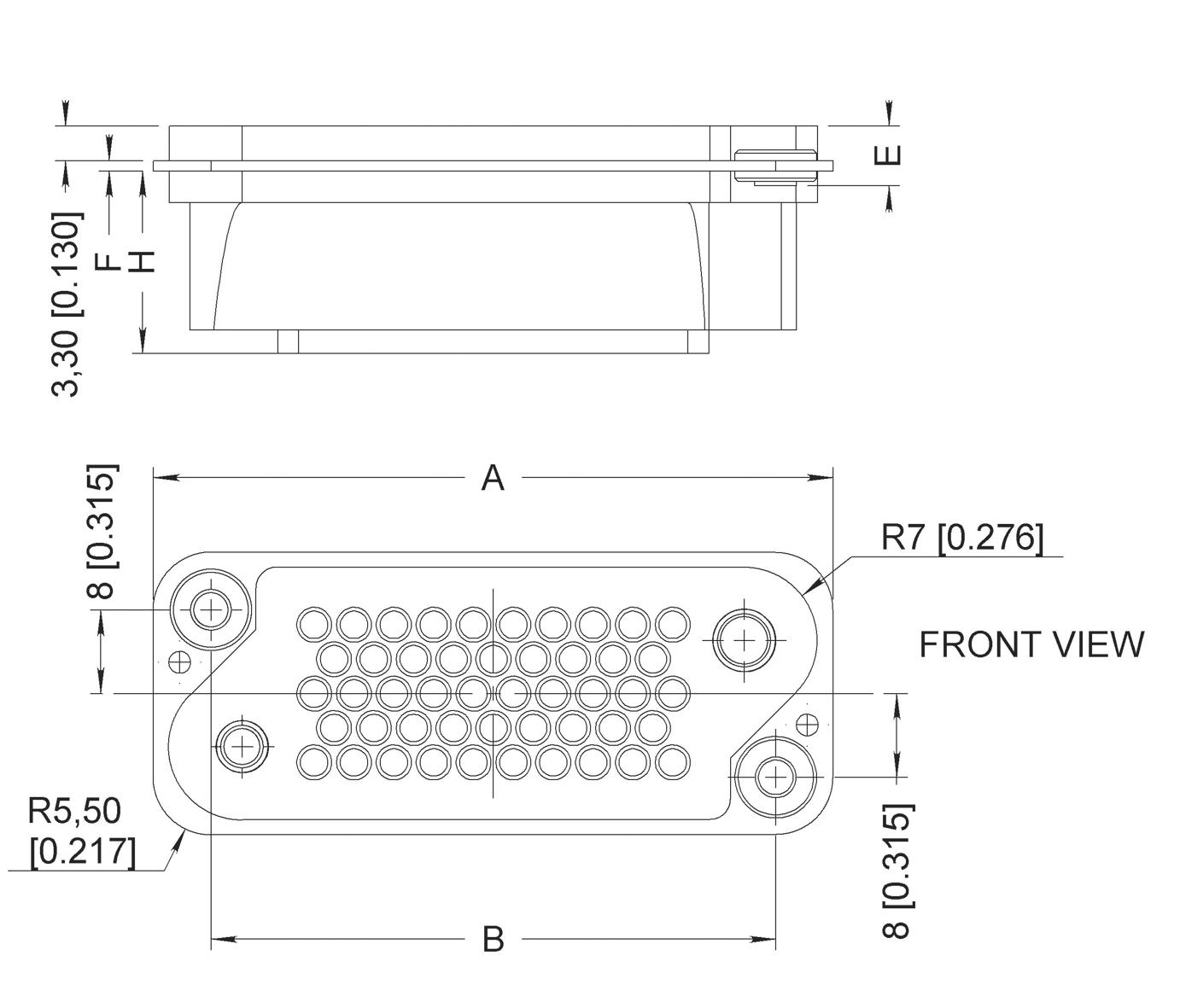
DIMENSIONS
SINGLE SHELL DIMENSIONS-MM(INCH)
MALE FEMALE
MATED SHELL DIMENSIONS
PANEL CUT-OUTS
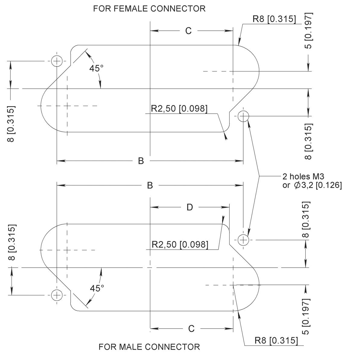
ARRANGEMENT
MCS-R Series
INTRODUCTION
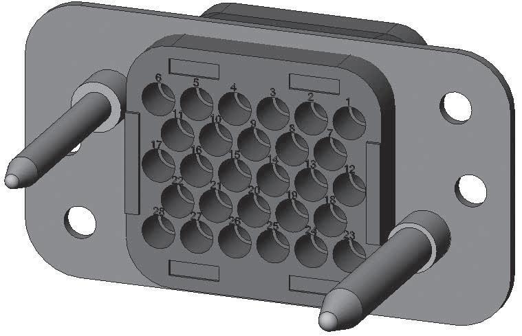
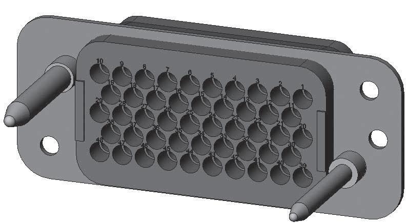
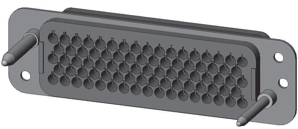
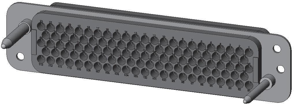
The MCSR series connectors are of robust design and available in four contacts arrangements, respectively 28, 48, 83 and 113 wire contacts, size gauge 16.
The same number of micro coaxial contacts can be installed instead of the wired contacts � A unique feature of the MCSR connector is that it’s interchangeable with the B series, however, it is not fully intermateable
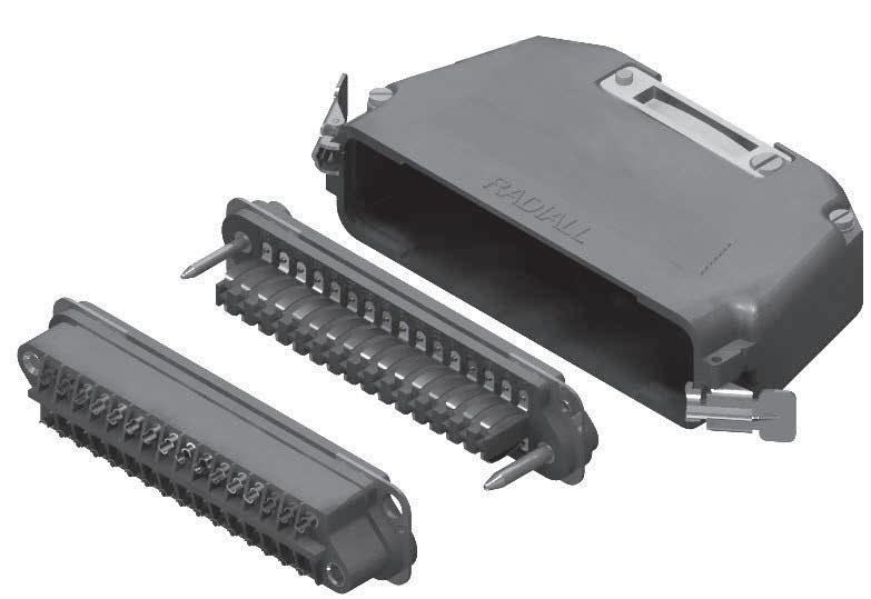
The connectors may be adapted with die cast aluminium hoods, with two types of cable entries, either from the top or from the side
APPLICATIONS
MCSR connectors are suitable for various applications in the following industrial fields: Communications and automation systems, electronic equipment, naval, aerospace, and defense applications �
FEATURES
The MCS-R series, plug and receptacle connectors are made of a thermostat insulator moulded onto a stainless steel fixing plate. Four contact arrangements are available, 28, 48, 83 and 113 contacts.
The plug connector is fitted with two guide pins of different diameter, which provides polarization and mate before the contacts ensuring a perfect alignment and reliability The plug connector accepts socket wire contacts or pin micro coaxial contacts
The receptacle connector accepts pin wire contacts or socket micro coaxial contacts and is fitted with floating eyelets which allows 0.75 mm radial float.
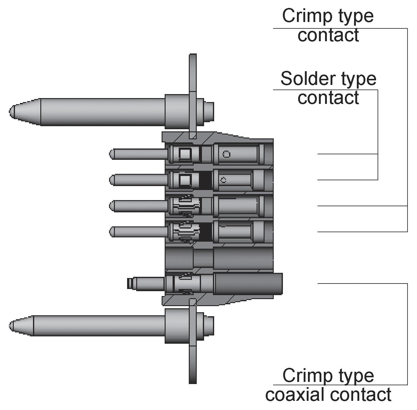
Three termination styles on the contacts are available, wire contacts with solder pot or crimp for wire size gauge 16 and micro coaxial contacts, crimp style�
MCS-R Series
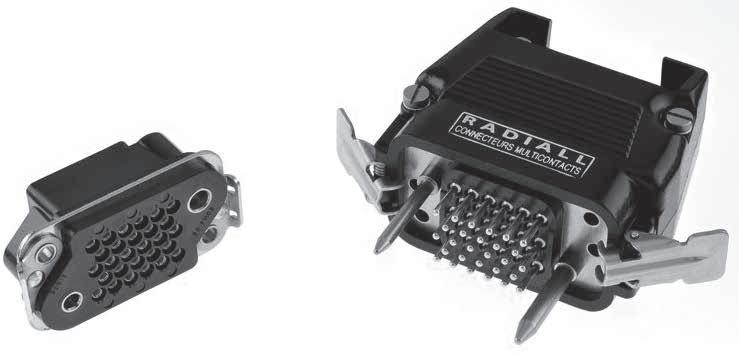
PRODUCT OVERVIEW
Detailed view of the various parts of this series connector
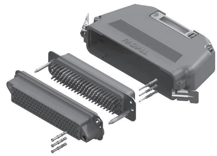
MCS-R Series
TECHNICAL CHARACTERISTICS
ELECTRICAL
• Current Rating by Contact: 13 A
• Operating Voltage: 350 Vrms at 50 Hz
• Test Voltage: 1,500 Vrms at 50 Hz
• Insulation Resistance: > 5,000 MΩ
• Contact Resistance: < 12 mΩ
ELECTRICAL WITH MICRO COAXIAL CONTACTS
• Impedance: 50 Ω
• Operating Frequency Range: 0 to 1,000 MHz
• VSWR of Pair of Contacts: < 1.4 from 0 to 1,000 MHz
• Insertion Loss of a Pair of Contacts at 1,000 MHz: < 0� 20 dB
• Test Voltage at Sea Level (Mated Pair): 600 Vrms at 50 Hz
• Insulation Resistance: > 5,000 MΩ
• Contact Resistance: < 12 mΩ
MECHANICAL & ENVIRONMENTAL
• Temperature Range: -55 °C (-131 °F) to +125 °C (+257 °F)
• Humidity: 21 Days
• Mating and Unmating: 500 Cycles
• Contact Retention: > 50 N
MCS-R Series
MATERIALS
DESCRIPTION
Insulator Block
Guide Pins
Fixing Plate
MASSES G (OZ)
MATERIAL/FINISH
Steel Contacts
PLUG
MCS-R Series
HOW TO ORDER CONNECTORS
The following indications are useful when ordering MCS-R connectors �
When ordering a connector with its locking system VP, brackets fitted on the female connector replace the eyelets, whilst the locking clips are always fitted on the backshell.
Series MCS-R contacts are removable Contacts shall be ordered separately following the termination style and quantities desired
For backshells and accessories please refer to page 9-18 to 9-19 for ordering
For contact references please refer to page 9-15�
SERIES PREFIX
CONTACT ARRANGEMENT
028–048–083-113
PRODUCT TYPE
M: Plug connector
F: Receptacle connector
MODIFICATION CODE
00: Without locking VP: Brackets for locking system receptacle only (see page 9-16 for detail)
TERMINATION STYLES
MCS-R Series
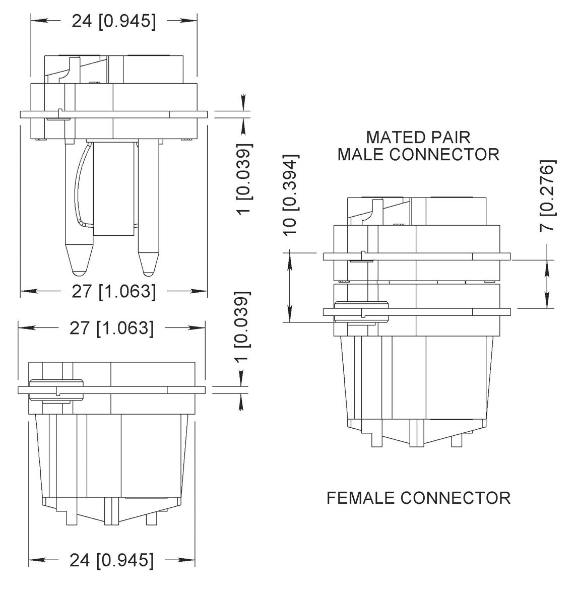
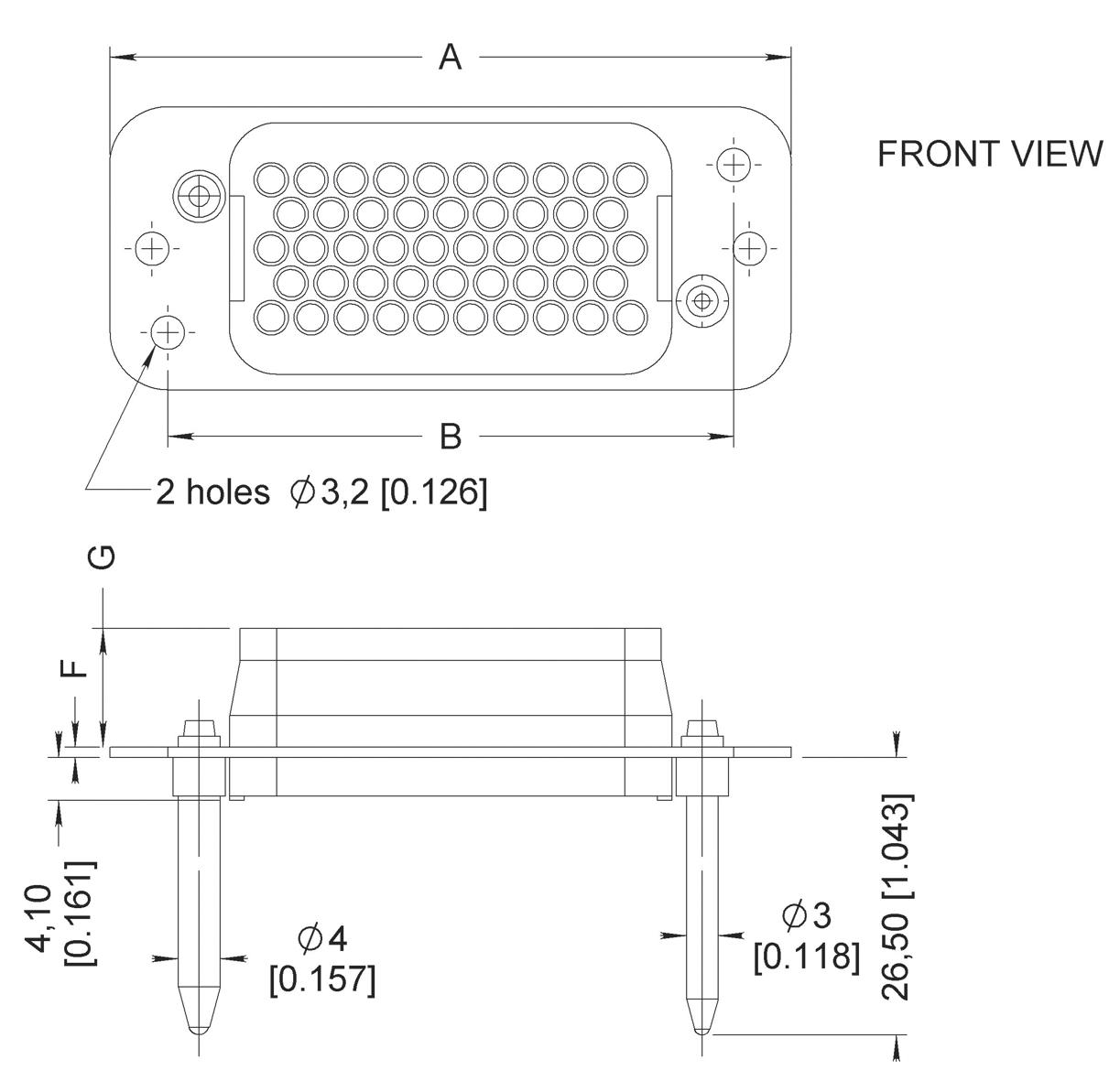
DIMENSIONS
SINGLE SHELL DIMENSIONS MM (INCH)
PLUG RECEPTACLE
MATED SHELL DIMENSIONS
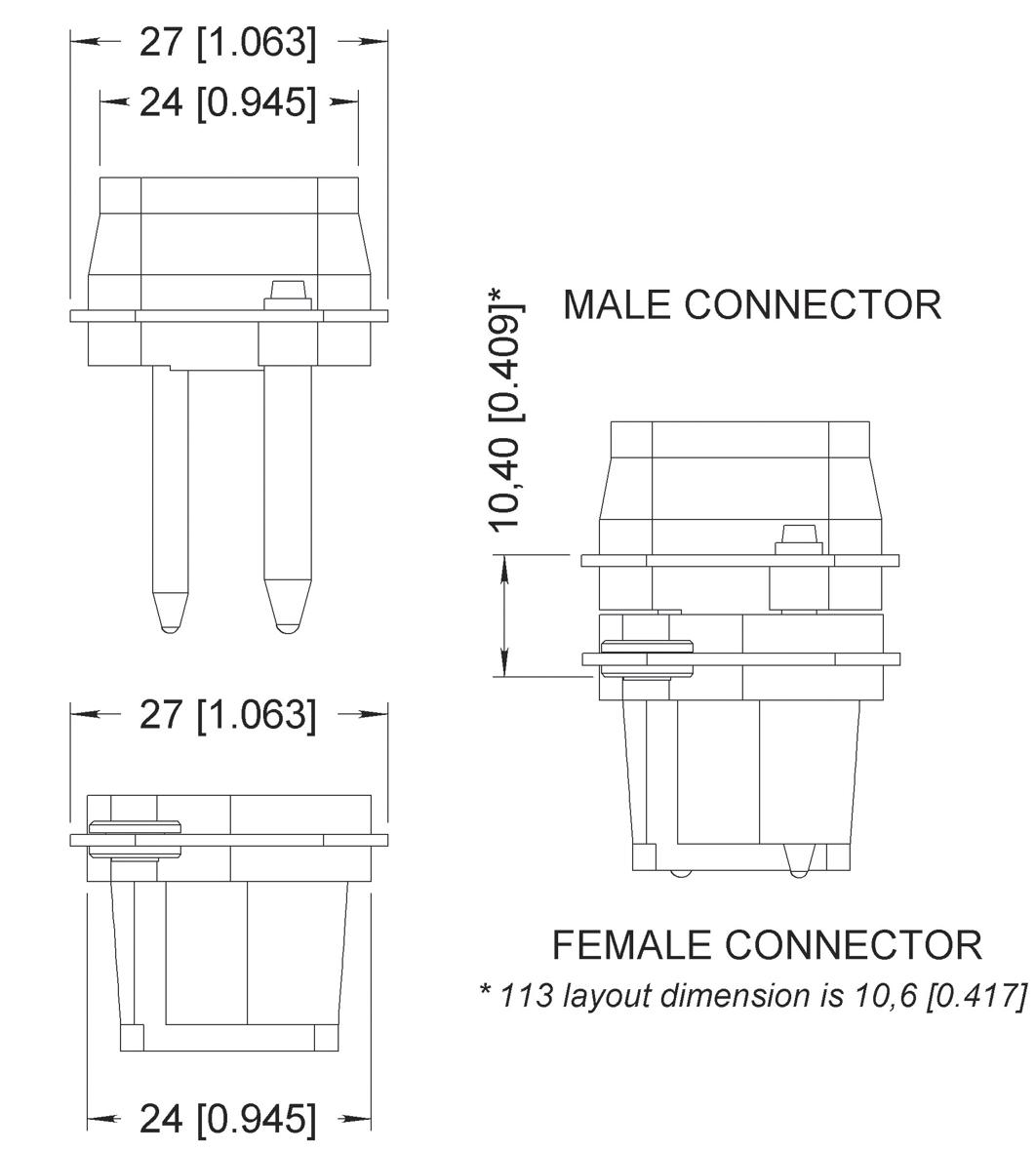
Plug
PANEL CUT-OUTS
Receptacle

CONTACT ARRANGEMENT
MCS-R Series
CONTACT REFERENCES
[1]
MICRO COAXIAL CONTACTS
CRIMP WIRE CONTACTS [2]
SOLDER WIRE CONTACTS [2]
Notes:
1. For other termination please consult us 2. Stripping length for cable types AWG16-18-20 is 6 and for types AWG20-22-24 it is 5
MCS-R Series
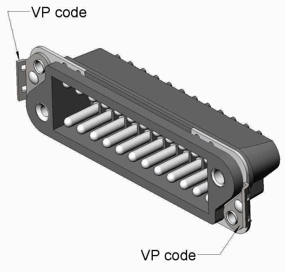
LOCKING SYSTEM CODE VP
The brackets can only be used on the receptacle connector and enables it to be fastened securely when its mating half is fitted with a hood
The brackets replace the floating eyelets on the receptacle connector
On both series B and MCSR when VP code is ordered, the corresponding hood must be ordered with the male connector
MCS-R Series
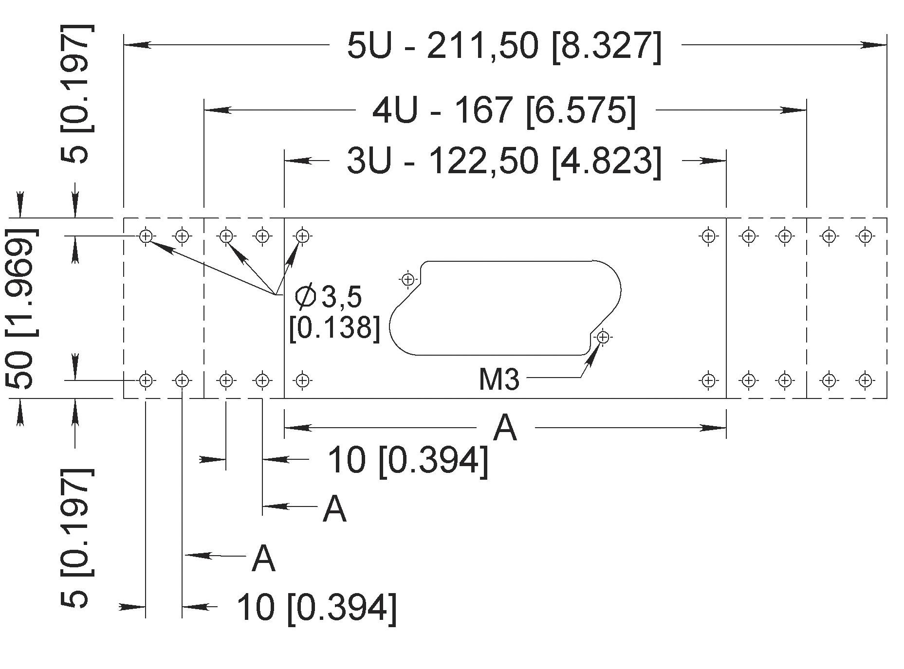
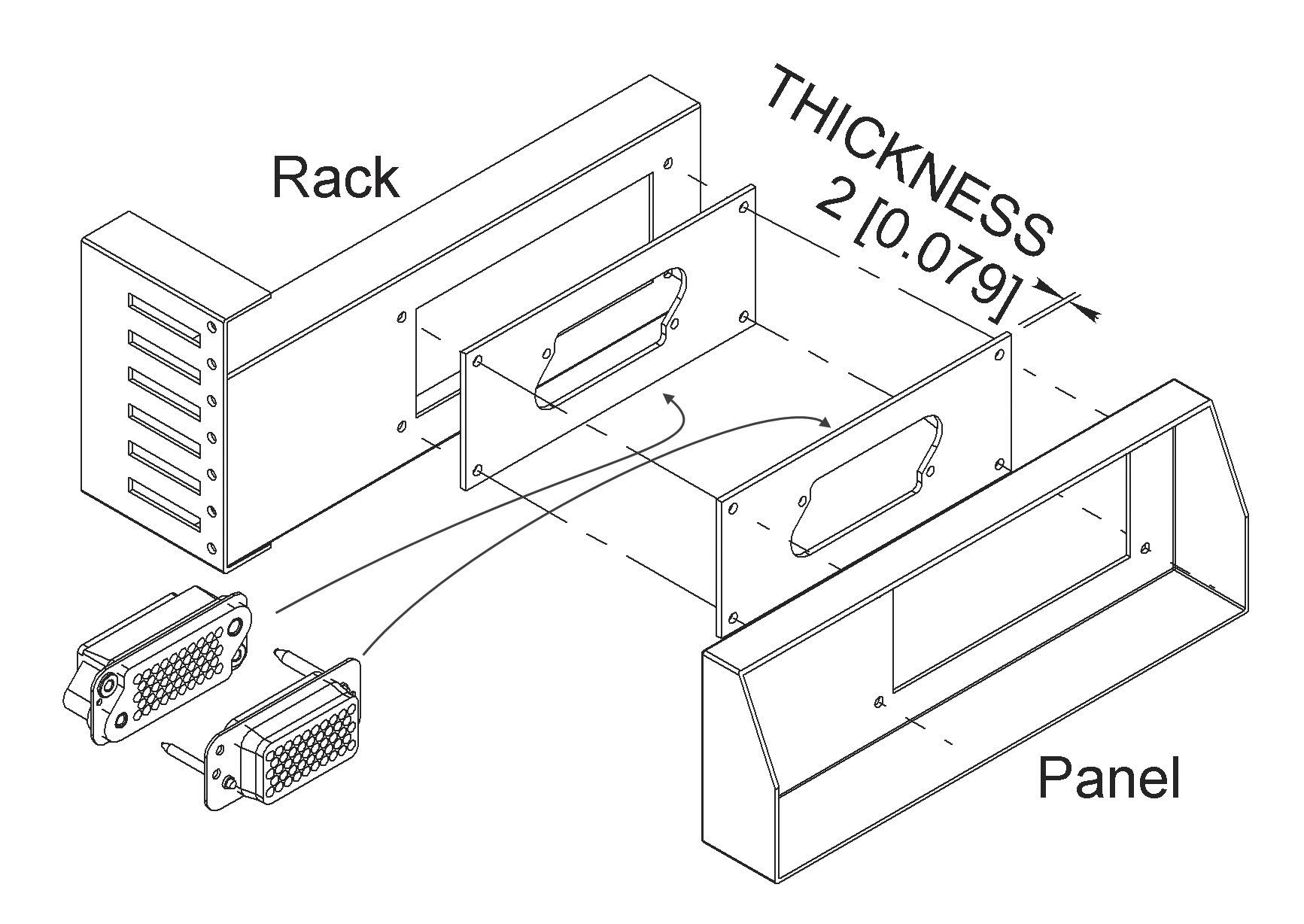
CONNECTORS MOUNTING PLATES
The mounting plates already blanked out, simplify the wall cut out on the rack or panel as well as on any other item designed to support the connector. The latter is directly fitted to the mounting plate, which can then be easily secured with accuracy on the equipment due to the four oblong holes of the mounting plate
MCS-R Series
CONNECTORS ACCESSORIES
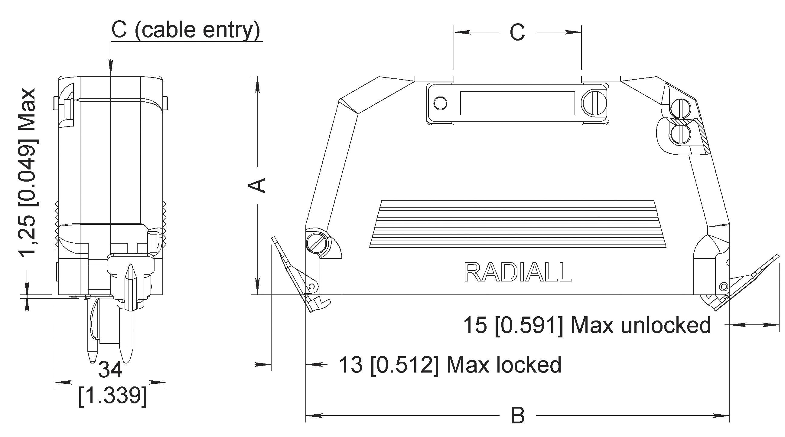
The backshells for both series B and MCSR are available in four sizes and are supplied in two halves which enables them to be fitted after the wiring of the connectors.
They are available either with TOP or SIDE (45°) cable entry�
Each backshell is fitted with a pair of locking clips, one fixed on each end. This allows the connector backshell assembly to be fastened securely to the mating connector fitted with the VP brackets.
TOP ENTRY
Notes 1. This screw is for grounding purpose.
SIDE ENTRY MCS-R Series
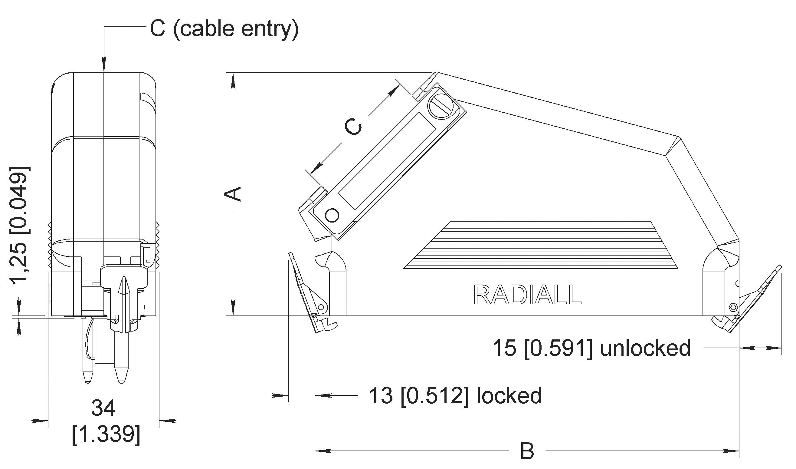
PART NUMBER FOR SIDE ENTRY
MCS-R Series
MICRO COAXIAL CONTACTS ASSEMBLY INSTRUCTIONS
Three different modes of assembly are to be considered depending on the cable type used. The two first assemblies A and B are applicable for braid coaxial cables, whilst the third assembly C is applicable for twin conductor cable� The three mounting procedures are identical for both contact types, pin and socket �
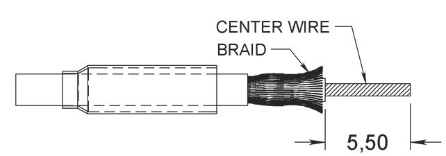
MOUNTING PROCEDURE COAXIAL CABLES
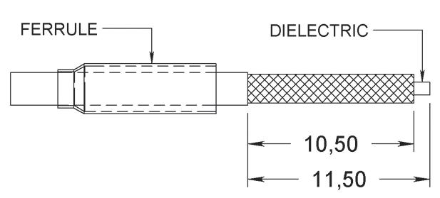
After sliding the ferrule over the cable and stripping the latter to the dimensions shown in A1
• Comb the braid in opening it up, strip the center wire to the dimension shown in A2�
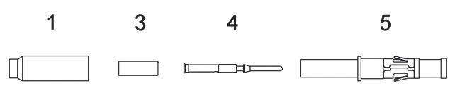
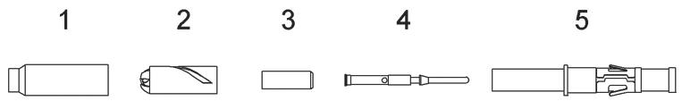
• Slide the insulator bushing [1] over the dielectric
• Place the center contact [2] over the conductor, the contact must butt against the insulator bushing [1] �
• Crimp the center contact with tool 282281�
• Slide the cable and contact into the body [3] ensuring that it’s pushed home, then trim back the braid over the body [3] �
• Slide the ferrule over the braid up to the body shoulder�
• Place the assembly into tool 282292 and crimp the ferrule�
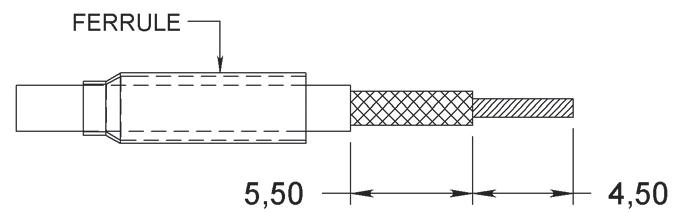
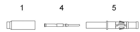
After sliding the ferrule over the cable, strip the latter to dimensions shown in B (mounting of coaxial contacts without insulator bushing)�
• Comb the braid and place the center contact over the conductor butting it against the dielectric �
• Place the sub assembly into tool 282281 and crimp the center contact �
• The following steps are identical to those indicated in A �
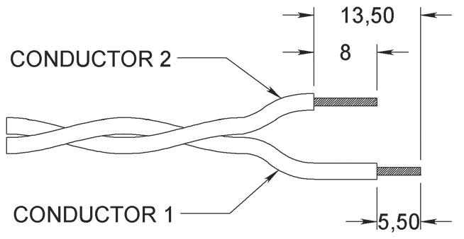
MICRO COAXIAL CONTACTS WITH TWIN CONDUCTOR CABLE
[4]
After sliding the ferrule over the twin conductors and stripping them to dimensions shown in C �
• Slide the adaptor 2 and the insulator bushing [1] over conductor 1�
• Place the center contact [2] over the conductor, butting it against the sheath
• Place the sub assembly into tool 282281 and crimp the centre contact
• Slide the cable and contact into the body [3] , ensuring that its home
• Slide the adaptor 2 onto the body [3] against the shoulder
• Place conductor 2 into the helical slot
• Slide the ferrule over the adaptor and conductor 2, up to the shoulder of the body [3]
• Place the assembly into tool 282292 and crimp the ferrule
Notes
1. Insulating bush
2. Socket or pin contact
3. Contact body
4. Conductor 1 is for the center contact, whilst conductor 2 is for earthing.
MCS-R Series
TOOLS
CRIMP TOOLS
PART NUMBER
282281
282291
282292
POSITIONERS
PART NUMBER
282973
MIL SPEC P/N
M22520/2-01
M22520/1-01
M22520/4-01

MIL SPEC P/N
M22520/4-02
282976 Daniels TP616
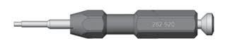
EXTRACTION TOOL
282975 Daniels TP617 PART NUMBER 282920