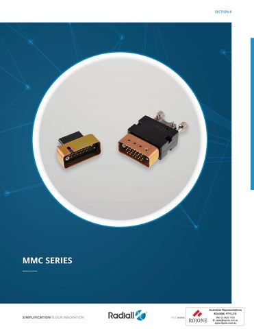
Radiall MMC Series Catalogue

Page 1

SIMPLIFICATION IS OUR INNOVATION Visit www.radiall.com for more information SECTION 8
SERIES
MMC
SIMPLIFICATION IS OUR INNOVATION Visit www.radiall.com for more information MMC SERIES | 8-1 INTRODUCTION Introduction 8-2 Applications 8-2 Features ������������������������������������������������������������������������������������������������������������������������������������������������������������������������������������� 8-2 Product Overview 8-3 Electrical Characteristics ��������������������������������������������������������������������������������������������������������������������������������������������������������� 8-4 Mechanical & Environmental Characteristics 8-4 Product Materials & Masses ���������������������������������������������������������������������������������������������������������������������������������������������������� 8-5 How To Order Connectors 8-6 Part Numbering ������������������������������������������������������������������������������������������������������������������������������������������������������������������������ 8-6 CONTACTS Contact Arrangements 8-7 to 8-8 Rack Guides Dimensions ��������������������������������������������������������������������������������������������������������������������������������������������� 8-9 to 8-10 Fixed Jackscrews Dimensions 8-11 to 8-12 Rotating Jackscrews Dimensions ����������������������������������������������������������������������������������������������������������������������������� 8-13 to 8-14 Block 104 Contacts 8-15 to 8-17 Block 158 Contacts ���������������������������������������������������������������������������������������������������������������������������������������������������� 8-18 to 8-19 Block 208 Contacts 8-20 to 8-21 Contacts ����������������������������������������������������������������������������������������������������������������������������������������������������������������������������������� 8-22 Front Release & Front Removable Contacts 8-22 Equipment Signal Contacts���������������������������������������������������������������������������������������������������������������������������������������������������� 8-23 Twisted Pair Crimp Contacts 8-24 Micro-Coaxial Contacts ���������������������������������������������������������������������������������������������������������������������������������������������������������� 8-25 Panel Cut-Out �������������������������������������������������������������������������������������������������������������������������������������������������������������������������� 8-26 Spare Parts for Guides 8-27 Spare Parts for Insulators, Backshells & Shrouds �������������������������������������������������������������������������������������������������������������� 8-28 Wiring Instructions 8-29 to 8-32 Tools ����������������������������������������������������������������������������������������������������������������������������������������������������������������������������������������� 8-33
Section 8 Table of Contents

Introduction

INTRODUCTION

The Radiall MMC series was designed in response to the majority of connection problems of cabling installation, internal and external on electrical and electronic equipment

The series conforms to the French specification NF-C-93 426 HE 621-622.

They are made up of a rectangular insulation block which accepts equally male or female contacts fitted with different types of wires and coaxial cables. A large number of accessories are available for the MMC series, including: backshell with cable clamp, contact protection shrouds, and locking� This makes it possible for the connector to be manufactured exactly to the corresponding needs of the user

APPLICATIONS

A simple, yet highly reliable construction makes the MMC offering enormously adaptable through use of the broad range of accessories � This has allowed the Radiall MMC series to be widely approved for the use in all civil and military fields such as computers, telecommunications, medical, aeronautical, naval and nuclear.

FEATURES

All of the contacts are removable in order to facilitate replacement, repairs or modification to circuits.

A range of robust manual and automatic tooling with easy to follow instructions provides straight-forward connector/ cable assembly. Fully conforms to the French specification NF-C-93 426 HE 621-622.

8-2 | MMC SERIES SIMPLIFICATION IS OUR INNOVATION Visit www.radiall.com for more information
© Eurocopter-Jérome DEULIN © Courtesy of US Army

Introduction

PRODUCT OVERVIEW

Detailed view of the various parts of this series connector�

JACKSCREWS RACK GUIDES

Rotating Fixing Rod, Used With Backshell

Rotating Fixing Rod, Used Without Backshell

Rotating Female Jackscrew

Fixing Male Jackscrew

Receptacle Connector

Washer & Nut, Used Without Backshell

Rotating Fixing Rod, Used With Backshell

SIMPLIFICATION IS OUR INNOVATION Visit www.radiall.com for more information MMC SERIES | 8-3
Shroud (Optional) Backshell Male Rack Guides Female Rack Guides Shroud (Optional) Washer & Nut Plug Connector

Introduction

ELECTRICAL CHARACTERISTICS

EQUIPMENT WIRE CONTACTS

COAXIAL CONTACTS

• Nominal Impedance: 50Ω

• Operating Frequency: 0 to 1,000 MHz

• Dielectric Withstanding Voltage: 600 Vrms at 50 Hz (At Sea Level)

• Insulation Resistance: ≥ 5,000 MΩ

• Contact Resistance: ≤ 12 mΩ

Loss by Pair (dB)

CONNECTORS

• Insulation Resistance: > 5,000 MΩ

• Dielectric Withstanding Voltage: 1,500 Vrms at 50 Hz (At Sea Level)

MECHANICAL & ENVIRONMENTAL CHARACTERISTICS

• Retention of the Contact in Moulding: > 50 N (11� 24 lbs)

• Mating Force per Contact Pair: < 3 � 4 N (0�76 lbs)

• Durability: 500 matings

• Vibration: 20 g (0�71 oz) from 80 to 2,000 Hz

• Shock: 50 g (1 76 oz)

• Temperature Range: -55 °C at +125 °C (-131 °F to 257 °F)

• Humidity: 21 days

• Salt Spray: 48H

8-4 | MMC SERIES SIMPLIFICATION IS OUR INNOVATION Visit www.radiall.com for more information
WIRE SECTION AWG 16 18 20 22 24 26 28 MM2 1.34 0.93 0.60 0.38 0.22 0.14 0.093 Current Rating (Amp) 13 10 7 5 5 3 2 1 Maximum Ø on Insulation 3 10 Contact Resistance ≤ 5 m Ω FREQUENCY 0–200MHZ 200–500 MHZ 500–1000 MHZ Voltage Standing Wave Ratio (VSWR) 1 10 1 15 1 40
015 < 0 025 < 0 025
Insertion
< 0

PRODUCT MATERIALS

Coaxial Contacts Body & Center Contacts Ferrule Insulator

PRODUCT MASSES

8 (0� 282)

11 (0 388)

7 (0 246) Plug Connector

19 (0 670) 42 22 (0 776)

690501 7 (0 246)

690511 8 (0� 282)

690521 11 (0 388)

690531 19 (0 670)

Receptacle Connector

690541 22 (0 776) 690962 2 (0�070) Rack

8 (0 282)

690965 6 (0 211) Short Jackscrew

690955

690949 18 (0 634)

690966 15 (0 529) Long Jackscrew

690956 16 (0 564)

690939 18 (0 634) REFERENCES MASSES

690940 15 (0� 529)

690941 16 (0 564)

690942 18 (0 634)

690943 22 (0 776)

690931 15 (0� 529)

Shroud Male

690930 14 (0 493) Shroud Female

690932 17 (0 599)

690933 25 (0 881)

690908 65 (2 292)

690911 77 (2 �716)

690905 57 (2 010) Backshell Top Entry

690914 101 (3 562)

690917 125 (4 409)

20521500 39 (1 375) Backshell Side Entry

(20) 690848002 16 (0 564)

(26) 690848003 18 (0�634)

(14) 690848001 14 (0 493) Strain Relief Top Entry

(50) 690848006 28 (0 987)

(75) 690848007 40 (1 410)

SIMPLIFICATION IS OUR INNOVATION Visit www.radiall.com for more information MMC SERIES | 8-5 Introduction
MATERIAL PLATING
Glass
-
Copper Alloy Gold Over Nickel Gold Over Nickel Nickel
DESCRIPTION
Connector
Filled Phenolic
Equipment Wire Contacts Body Spring Retention Clip
Copper Alloy Copper Alloy PTFE Gold Over Nickel Nickel Rack Guide Brass Nickel-Plated Jackscrews Stainless SteelShroud Steel Yellow Chromate Cadmium Plated Backshell Zinc or Aluminium Alloy Painted Black Strain
Clamp Stainless SteelSIZE
(OZ) TYPE 14
20
Relief Cable
MASSES G
26
34
Guide 690952 690963
690953
TYPE
G (OZ)

Introduction

HOW TO ORDER CONNECTORS

A pair of MMC connectors is made up of the following:

• A block “P” (plug)

• A block “R” (receptacle)

Of identical dimensions but distinguished by:

• The engraved letters “P” and “R” on the mating faces

• The contact identification and position of the cavities is a mirror image of the mating half.

Each block “P” and “R” must be fitted with male and female guides or jackscrews.

• On the block P female guide beside hole 1 or A

• On the block R male guide beside hole 1 or A (in order to prevent mismatching and misalignment)

PART NUMBERING

Connectors with guides (without other accessories)

SERIES

Basic code (see table below for selection)

CONNECTORS WITH ACCESSORIES

SERIES

BASIC CODE (see table below for selection)

MANDATORY

ACCESSORIES [2]

O: No accessories

A: Backshell top entry

B: Backshell side entry (only 75 way)

C: Top entry strain relief clamp (not available in 34 and 42 way)

SHROUDS

O: No shroud

A: Male shroud without polarizing [1]

Male shroud with polarizing [2]

F: Female shroud without polarizing [1]

Female shroud with polarizing [2]

Example: 701 goes with 602

Notes

1. Not available in 42 way

2. Not available in 14 way

When connector has a shroud with polarizing, polarization starts from the cavity A or 1 side of the connector (refer to page 8-28)

8-6 | MMC SERIES SIMPLIFICATION IS OUR INNOVATION Visit www.radiall.com for more information
IN 1 3 5 7 CODE B C D E IN 1 3 5 7 CODE G H J K NUMBER OF CONTACTS RACK GUIDES FIXED JACKSCREWS ROTATING JACKSCREWS PLUG RECEPTACLE PLUG RECEPTACLE PLUG RECEPTACLE 14 400 500 701 700 600 602 20 410 510 711 710 610 612 26 420 520 721 720 620 622 34 430 530 731 730 630 632 42 440 540 741 740 640 642 50 450 550 751 750 650 652 75 460 560 761 760 660 662
690 690
600 600 O O A

Contacts

CONTACT ARRANGEMENTS

VIEW WIRING SIDE MM (INCH)

SIMPLIFICATION IS OUR INNOVATION Visit www.radiall.com for more information MMC SERIES | 8-7 14
20
26
CONTACTS
CONTACTS
CONTACTS

Contacts

CONTACT ARRANGEMENTS

VIEW WIRING BLOCK MM (INCH)

50 CONTACTS

HEIGHT DIMENSIONS MM (INCH)

14, 20, 26, 34, 42 CONTACTS

75 CONTACTS

50, 75 CONTACTS

8-8 | MMC SERIES SIMPLIFICATION IS OUR INNOVATION Visit www.radiall.com for more information

Contacts

RACK GUIDES DIMENSIONS

CONNECTOR BLOCK MM (INCH)

STRAIN RELIEF CABLE CLAMP (TOP ENTRY) MM (INCH)

SIMPLIFICATION IS OUR INNOVATION Visit www.radiall.com for more information MMC SERIES | 8-9
NUMBER
B C MALE FEMALE MALE FEMALE 14 10 1 ( 397) 34 8 (1 370) 37 2 (1 464) 14 2 ( 559) 16 6 ( 653) 20 42 2 (1 661) 45 1 (1 775) 26 44 � 2 (1�740) 46 �1 (1� 826) 17� 3 (�681) 19� 4 (�764) 34 10 3 ( 405) 54 (2 126) 56 4 (2 220) 22 2 ( 874) 24 6 ( 968) 42 Shroud Not Available 50 10 3 ( 405) 72 (2 834) 74 6 (2 937) 25 3 ( 996) 27 8 (1 094) 75 72 4 (2 850) 74 7 (2 940) 34 4 (1 354) 37 (1 456) NUMBER OF CONTACTS D E CABLE ENTRY DIMENSIONS F G MAX 14 44 (1 732) 31 5 (1 240) 5 ( 0197) 8 (0 315) 20 39 5 (1 555) 12 (0 472) 26 41 1 (1 618) 10 (0 394) 34 Cable Clamp Not Available 42 50 53 (2 086) 65 6 (2 582) 26 (1 023) 14 (0 551) 75 18 (0 708)
OF CONTACTS A

Contacts

RACK GUIDES DIMENSIONS

BACKSHELL TOP ENTRY-MM (INCH)

BACKSHELL SIDE ENTRY-AVAILABLE ONLY FOR 75 WAY MM (INCH)

8-10 | MMC SERIES SIMPLIFICATION IS OUR INNOVATION Visit www.radiall.com for more information
OF
H I CABLE ENTRY DIMENSIONS L J K MAX 14 46 (1 811) 39 (1 535) 7 6 (0 299) 13 (0 512) 17 (0 670) 20 47 (1 850) 15 (0 590) 26 48 5 (1 909) 17 (0 670) 17 (0 670) 21 (0 827) 34 52 5 (2 067) 53 5 (2 106) 22 (0 866) 20 (0 787) 24 (0 945) 42 47 (1� 850) 61 (2 � 401) 32 (1� 260) 12 (0� 472) 21� 5 (0� 846) 50 66 5 (2 618) 68 5 (2 697) 26 (1 023) 21 (0 827) 25 (0 984) 75 47 (1 850) 68 (2 677) 40 (1 575) 30 5 (1 200)
NUMBER
CONTACTS

Contacts

FIXED JACKSCREWS DIMENSIONS

CONNECTOR

BLOCK MM (INCH)

STRAIN RELIEF CABLE CLAMP (TOP ENTRY) MM (INCH)

SIMPLIFICATION IS OUR INNOVATION Visit www.radiall.com for more information MMC SERIES | 8-11
NUMBER OF
A B C MALE FEMALE MALE FEMALE 14 10 1 (0 397) 34 8 (1 370) 37 2 (1 464) 14 2 (0 559) 16 6 (0 653) 20 42 2 (1 661) 45 1 (1 775) 26 44 2 (1 740) 46 4 (1 827) 17 3 (0 681) 19 4 (0 764) 34 10 3 (0 405) 54 (2 126) 56 4 (2 220) 22 2 (0 874) 24 6 (0 968) 42 Shroud Not Available 50 10 3 (0 405) 72 (2 834) 74 6 (2 937) 25 3 (0 996) 27 8 (1 094) 75 72 4 (2 850) 74 7 (2 940) 34 4 (1 354) 37 (1 456) NUMBER OF CONTACTS D E CABLE ENTRY DIMENSIONS F G MAX 14 44 (1 732) 31� 5 (1� 240) 5 (0�197) 8 (0� 315) 20 39 5 (1 555) 12 (0 472) 26 41 1 (1 618) 10 (0 394) 34 Cable Clamp Not Available 42 50 53 (2 �086) 65 �6 (2 � 582) 26 (1�023) 14 (0 551) 75 18 (0�708)
CONTACTS

Contacts

FIXED JACKSCREWS DIMENSIONS

BACKSHELL TOP ENTRY-MM (INCH)

BACKSHELL SIDE ENTRY-AVAILABLE ONLY FOR 75 WAY MM (INCH)

8-12 | MMC SERIES SIMPLIFICATION IS OUR INNOVATION Visit www.radiall.com for more information
NUMBER OF
H I CABLE ENTRY DIMENSIONS L J K MAX 14 46 (1� 811) 39 (1 535) 7 6 (0 299) 13 (0 512) 17 (0 670) 20 47 (1� 850) 15 (0� 590) 26 48 5 (1 909) 17 (0 670) 17 (0 670) 21 (0 827) 34 52 5 (2 067) 53 5 (2 106) 22 (0 866) 20 (0 787) 24 (0 945) 42 47 (1 850) 61 (2 401) 32 (1 260) 12 (0 472) 21 5 (0 846) 50 66 5 (2 618) 68 5 (2 697) 26 (1 023) 21 (0 827) 25 (0 984) 75 47 (1 850) 68 (2 677) 40 (1 575) 30 5 (1 200)
CONTACTS

Contacts

ROTATING JACKSCREWS DIMENSIONS

STRAIN RELIEF CABLE CLAMP (TOP ENTRY) MM (INCH)

SIMPLIFICATION IS OUR INNOVATION Visit www.radiall.com for more information MMC SERIES | 8-13
NUMBER OF CONTACTS A B C MALE FEMALE MALE FEMALE 14 10 1 (0 397) 34 8 (1 370) 37 2 (1 464) 14 2 (0 559) 16 6 (0 653) 20 42 2 (1 661) 45 1 (1 775) 26 44 � 2 (1�740) 46 � 4 (1� 827) 17� 3 (0�681) 19� 4 (0�764) 34 10 3 (0 405) 54 (2 126) 56 4 (2 220) 22 2 (0 874) 24 6 (0 968) 42 Shroud Not Available 50 10 3 (0 405) 72 (2 834) 74 6 (2 937) 25 3 (0 996) 27 8 (1 094) 75 72 4 (2 850) 74 7 (2 940) 34 4 (1 354) 37 (1 456) NUMBER OF CONTACTS D E M CABLE ENTRY DIMENSIONS F G MAX 14 44 (1 732) 31 5 (1 240) 60 (2 362) 5 (0 197) 8 (0 315) 20 39 5 (1 555) 12 (0 472) 26 41 1 (1 618) 10 (0 394) 34 Cable Clamp Not Available 42 50 53 (2 086) 65 6 (2 582) 64 (2 519) 26 (1 023) 14 (0� 551) 75 18 (0 708)
MM
CONNECTOR BLOCK
(INCH)

Contacts

ROTATING JACKSCREWS DIMENSIONS

BACKSHELL TOP ENTRY MM (INCH)

BACKSHELL SIDE ENTRY-AVAILABLE ONLY FOR 75 WAY MM (INCH)

8-14 | MMC SERIES SIMPLIFICATION IS OUR INNOVATION Visit www.radiall.com for more information
OF
H I CABLE ENTRY DIMENSIONS L N J K MAX 14 46 (1 811) 39 (1� 535) 7�6 (� 299) 13 ( 512) 17 ( 670) 60 (2 362) 20 47 (1 850) 15 ( 590) 26 48 5 (1 909) 17 ( 670) 17 ( 670) 21 ( 827) 34 52 5 (2 067) 53 5 (2 106) 22 ( 866) 20 ( 787) 24 ( 945) 64 (2 519) 42 47 (1 850) 61 (2 401) 32 (1 260) 12 ( 472) 21 5 ( 846) 50 66 � 5 (2 �618) 68 � 5 (2 �697) 26 (1�023) 21 (� 827) 25 (�984) 78 (3 �071) 75 47 (1 850) 68 (2 677) 40 (1 575) 30 5 (1 200)
NUMBER
CONTACTS

Contacts

BLOCK 104 CONTACTS

Mates with All the Blocks P

Central Rack Guide

690473 Central Jackscrew

690478

VIEW WIRING SIDE MM (INCH)

SIMPLIFICATION IS OUR INNOVATION Visit www.radiall.com for more information MMC SERIES | 8-15
R TYPE-RACK
PART NUMBER A B C D
CENTRAL GUIDE
GUIDES
No Guides
Male Male Female
- - Female
Female Female Female
CENTRAL
P TYPE-RACK
PART NUMBER A B C D
No Guides
Male Female Female Male 690480 Male - - Male
Male Male Male Male
690571 Female
690570 Female
690572 Female
690573
GUIDE
GUIDES
690481
690482
690483
No Guides
Male Female Female Male
Male - - Male
Male Male Male Male
No Guides
Female Female Male
- - Male
Male Male Male
Sunken Hex � Nut 4 A/F
690471
690470
690472
690476 Male
690475 Male
690477 Male
RACK GUIDE SUNKEN HEX. NUT CENTRAL JACKSCREW

Contacts

Detailed view of the connector with shroud mounted on a panel�

VIEW ONCE ALL ASSEMBLED

8-16 | MMC SERIES SIMPLIFICATION IS OUR INNOVATION Visit www.radiall.com for more information
TOP ENTRY MM
BACKSHELL
(INCH)

GUIDES TO MOUNT IN POSITIONS A, B, C, D

FEMALE P/N 690950

SHROUDS

MALE P/N 690960

FEMALE SHROUD-USE ONLY THIS REFERENCE TO ORDER WITHOUT POLARIZING CODE

POLARIZATION

Contacts SHROUD FEMALE

MALE SHROUD-USE ONLY THIS REFERENCE TO ORDER WITHOUT POLARIZING CODE

To order with polarizing: add the polarization code at the end of the shroud part number, see example: 690991110.

BACKSHELL–CAST ALUMINIUM PAINTED BLACK ASSEMBLY KIT

1 entry 45° 7 8 (3 1) 70 (27 6) 71 (28) 690971

2 entries 45° 15 6 (6 1) 690972

1 entry 0° 5 3 (2 1) 55 (21 7) 66 (26) 690973

2 entries 0° 10 6 (4 2) 690974

1 entry 90° 5 � 3 (2 �1) 65 (25 6) 57 (22 4) 690973

2 entries 90° 10 6 (4 2) 690974

SPARE PARTS (1 OR 2 ENTRY ROTATION)

DESCRIPTION

Body (In 2 Parts) 690977

Entry 0–90° 690980

Entry 45° 690979

Cap 690978

SIMPLIFICATION IS OUR INNOVATION Visit www.radiall.com for more information MMC SERIES | 8-17
CODE POSITION 110 1 120 3 130 5 140 7 210 1 + 3 220 3 + 5 230 5
7 240 1
5 250
7 260
ENTRY CABLE CLAMP
CM_
L H PART NUMBER
+
+
3 +
1 + 7
MAX
(INCH)
PART NUMBER
REF: 690 992 REF: 690 991
SHROUD MALE

BLOCK 158 CONTACTS Contacts

CENTRAL GUIDE WITHOUT GUIDES 4 FEMALE 2 MALE/ 2 FEMALE

Mates with All Blocks P 690686 690670 690680

GUIDE WITHOUT GUIDES 4 FEMALE 2 MALE/ 2 FEMALE

Central Rack Guide 690681 690678 690683

Sunken Hex 4 A/F 690671 690679 690684

Central Jackscrew 690676 690677 690682

8-18 | MMC SERIES SIMPLIFICATION IS OUR INNOVATION Visit www.radiall.com for more information
R TYPE GUIDES SUPPLIED UNMOUNTED
CENTRAL
P TYPE GUIDES SUPPLIED UNMOUNTED
VIEW WIRING SIDE MM (INCH) RACK GUIDE SUNKEN HEX. NUT CENTRAL JACKSCREW

Contacts

GUIDES TO MOUNT IN POSITIONS A, B, C, D-MM (INCH)

FEMALE P/N 690950

MALE P/N 690960

BACKSHELL P/N 690985-MM (INCH)

SIMPLIFICATION IS OUR INNOVATION Visit www.radiall.com for more information MMC SERIES | 8-19

Contacts

BLOCK 208 CONTACTS

POLARIZING POSITIONS

GUIDES SUPPLIED UNMOUNTED

4 FEMALE 2 MALE/2 FEMALE

N 690768001 690778004

R 690768002 690778007

Z 690768003 690778002

Y 690768004 690778003

X 690768005 690778001

W 690768006 690778005

POLARIZING POSITIONS GUIDES SUPPLIED UNMOUNTED

4 FEMALE 2 MALE/2 FEMALE

N 690769001 690767001

R 690769002 690767002

Z 690769003 690767003

Y 690769004 690767004

X 690769005 690767005

W 690769006 690767006

8-20 | MMC SERIES SIMPLIFICATION IS OUR INNOVATION Visit www.radiall.com for more information
VIEW WIRING SIDE MM (INCH)

Contacts

GUIDES TO MOUNT IN POSITIONS A, B, C, D-MM (INCH)

FEMALE P/N 690958

MALE P/N 690968

BACKSHELL P/N 690982-MM (INCH)

SIMPLIFICATION IS OUR INNOVATION Visit www.radiall.com for more information MMC SERIES | 8-21

Contacts

CONTACTS

Pins and/or sockets for equipment wire, twisted pairs and coaxial cable can be housed in either plug or receptacle giving a multitude of connection possibilities �

Many contact arrangements available: 14 -20-26-34-42-50-75-104-158 and 208 ways.

The signal contacts size 16 (pin Ø 1� 58mm) are for crimping to AWG 16 to 28 �

Contacts for wire wrapping are available with tails 0 6 x 0 6 mm (0 024x0 024 inch) or 1 2 x 1 2mm (0 047 x 0 047 inch)

square The coaxial contacts are for crimping to 2 mm and 2 6 mm coaxial cables and AWG 24 to 30 twisted pairs

For all other contact terminations: consult us

No tool is necessary for the insertion, the extraction is from the rear using an extraction tool introduced by the mating face of the connector�

FRONT RELEASE & FRONT REMOVABLE CONTACTS

In order to facilitate the junction of MMC series connectors with a flexible or steady printed circuits, Radiall created a range of solder tail and wire wrap front release contacts

This eases the replacement of a damaged contact without rewiring the set �

These size 16 contacts fit with all standard MMC connectors cavities from 14 to 208 which allow to mix them on a same connector with micro-coaxial contacts and crimping contacts �

Mini-Wrapping

0 6 ( 024) Flats 2 Wraps

Mini-Wrapping

L=10 6 ( 417) 690220 690320 690220001 690320001

0 6 ( 024) Flats 3 Wraps L=16 ( 630) 690221 690321 690221001 690321001

PC Tail Ø 0 65mm ( 026) L=6 2 ( 244) 690222 690322 690222001 690322001

INSTALLATION AND EXTRACTION OF FR/FR CONTACTS.

CONTACT INSTALLATION

1. Insert the contact fitted with the retention clip through the mating face and push insertion tool 282501

2� Introduce the sleeve by the rear face with tool 282502 and push it until it flushes with the insulator.

Notes

CONTACT REPLACEMENT

Extraction: insert the extraction tool 282917 by the mating face into the cavity of the contact to be replaced Push it until it butts against the contact shoulder� Maintain the pressure on piston and pull on body tool to extract the contact � To free the contact release pressure on piston

Installation of a new contact without retention clip: insert the contact through the mating face, push it with tool 282501 until contact snaps in place

1. Contact with retention clip and anti-rotation sleeve, must be used for the original or initial equipment of the connectors.

2. Contact without retention clip and anti-rotation sleeve for the replacement of damaged contacts.

8-22 | MMC SERIES SIMPLIFICATION IS OUR INNOVATION Visit www.radiall.com for more information
TYPE
CONTACT
PIN SOCKET PIN SOCKET
CONTACTS ARRANGEMENTS
[1] REPLACEMENT CONTACT [2]

EQUIPMENT SIGNAL CONTACTS

WIRE WRAP CONTACTS

Mini-Wrapping

Ø 0 6 (0 024) Flats 2 Wraps

Ø 1 2 (0 047) Flats 3 Wraps

SIMPLIFICATION IS OUR INNOVATION Visit www.radiall.com for more information MMC SERIES | 8-23
CABLES CONTACTS POSITIONER CRIMPING TOOL POSITION ON CRIMP TOOL EXTRACTION TOOL PIN SOCKET AWG SIZE SECTION IN MM2 (SQ.IN) Ø MAX. ON SLEEVE MM (INCH) 16 18 20 1 34 (0 053) 0 93 (0 037) 0 60 (0 024) 3 10 (0 122) 690200 690300 282975 282291 M22520/1 01 6 5 4 282920 16 18 20 1 34 (0 053) 0 93 (0 037) 0 60 (0 024) 3 10 (0 122) 690201 690301 6 5 4 20 22 24 0 60(0 024) 0 38 (0 015) 0 22 (0 009) 2 20 (0 086) 690215 690315 282976 4 3 2 282920 24 26 28 0� 22 (0�009) 0 14 (0 006) 0 093 (0 004) 1�60 (0 063) 690235 690335 4 2 2
FRONT RELEASE/REAR RELEASE CRIMP CONTACTS
TYPE CONTACTS ARRANGEMENTS CONTACTS TOOLS PIN SOCKET INSERTION EXTRACTION
L=10 6
690241 690341 282921 282920
L=19
690240 690340
(0 417)
Wrapping Standard
5 (0 767)
Contacts

TWISTED PAIR CRIMP CONTACTS

5.

8-24 | MMC SERIES SIMPLIFICATION IS OUR INNOVATION Visit www.radiall.com for more information CABLES TOOLS [3] CONTACTS & WIRING INSTRUCTIONS [4] CENTER CONTACT OUTER CONTACT SOCKET [1] PIN [2] AWG SIZE SECTION IN MM 2 (SQ.IN) Ø MAX. ON INSULATOR POSITION ON CRIMPING TOOL [5] POSITIONER CIMPING TOOL POSITIONER 24 Stranded Wire Cable 0 22 (0 009) 0 96 (0 038) 2 282981/M22520/2 � 04 282292 /M22520/4 01 282973/M22520/4 02 690070 B 690170 B 26 Stranded Wire Cable 0 14 (0 006) 0 84 (0 033) 2 690060 A 690160 A 28 0 093 (0 004) 0 73 (0 029) 1 30 0 055 (0 002) 0 66 (0 026) 1 26 Single Wire Cable 0 12 (0 005) 0 85 (0 033) 3 28 0 08 (0 003) 0 67 (0 026) 2 30 0 05 (0 002) 0 58 (0 023) 1 26 Stranded Wire Cable 0 14 (0 006) 0 84 (0 033) 2 690061 A 690161 A 28 0 093 (0 004) 0 73 (0 029) 1 26 Single Wire Cable 0 12 (0 005) 0 85 (0 033) 3 28 0 08 (0 003) 0 67 (0 026) 2 30 Stranded Wire Cable 0 055 (0 002) 0 66 (0 026) 1 690062 A 690162 A 30 Single Wire Cable 0 05 (0 002) 0 58 (0 023) 1 Notes
female
male contact 2.
male contact/center female contact 3.
tool for all twisted pair contacts P/N 282920
instructions on pages 8-29 to 8-32
1. Body
contact/center
Body
Extraction
4. Wiring
Crimping tool for all 282281/M22520/2.01
Contacts

Contacts

COAXIAL CRIMP CONTACTS

1. Body female contact/center male contact 2. Body male contact/center female contact

3. Extraction tool for all twisted pair contacts P/N 282920

4. Wiring instructions on pages 8-29 to 8-32

SIMPLIFICATION IS OUR INNOVATION Visit www.radiall.com for more information MMC SERIES | 8-25
Notes
TOOLS [3] CONTACTS & WIRING INSTRUCTIONS [4] CENTER CONTACT OUTER CONTACT SOCKET [1] PIN [2] CABLE REFERENCE IMPEDANCE Ω OUTER DIAMETER CRIMP TOOL POSITIONER CRIMP TOOL POSITIONER RG178/U RG196/U
50 2 (0 079) 282281 M22520/2 01 282981 M22520/2 � 04 282292 M22520/4 01 282973 M22520/4 � 02 690020 C 690120 C
RG316/U KX22 50 2 54 (0 100) ± 0 13 (0 005) 690040 D 690140 D RG179/U 75
CABLES
KX21
KX3A

Contacts

PANEL CUT-OUT

8-26 | MMC SERIES SIMPLIFICATION IS OUR INNOVATION Visit www.radiall.com for more information NUMBER OF CONTACTS A B C MAX. PANEL THICKNESS 14 12 4 (0 488) 23 8 (0 937) 20 8 (0 819) 6 (0 236) 20 12 4 (0 488) 31 7 (1 248) 28 7 (1 130) 26 15 7 (0 618) 33 3 (1 311) 29 2 (1 150) NUMBER OF CONTACTS A B C D E F MAX. PANEL THICKNESS 34 19 8 (0 779) 11 9 ( 468) 6 3 (0 248) 49 3 (1 940) 42 8 (1 685) 36 6 (1 441) 6 (0 236) 42 56 9 (2 240) 50 5 (1 988) 43 7 (1 720) 50 64 � 3 (2 � 531) 57�9 (2 � 279) 51�6 (2 �031) 75 29 (1 141) 19 4 (0 764) 14 2 (0 559) 104 29 3 (1 153) 20 6 (0 811) 12 7 (0 500) 72 5 (2 854) 63 5 (2 500) 55 6 (2 189) 5 5 (0 216)
208 CONTACTS
158 CONTACTS

SPARE PARTS Contacts

Jackscrew and rack guide selection table

SIMPLIFICATION IS OUR INNOVATION Visit www.radiall.com for more information MMC SERIES | 8-27
CABLES NUMBER OF CONTACTS 14 20 42 50 75 Rack Guides Without backshell Male 690962 Female 690952 With backshell Male 690963 690963 Female 690963 690963 Fixed Guides Without backshell Male 690961 Female 690951 With backshell Male 690964 690961 Female 690951 Rotating
Without backshell Male 690965 Female 690955 With or without backshell Male 690966 690949 690967For 75 Contacts 690967001 Side Entry Female 690956 690939For 75 Contacts 690957001 Side Entry
jackscrews

Contacts

SPARE PARTS

INSULATOR BLOCKS ONLY

NUMBER OF CONTACTS BLOCK

690401 690501

20 690411 690511

26 690421 690521 34 690431 690531 42 690441 690541

50 690451 690551 75 690461 690561

BACKSHELLS NUMBER OF CONTACTS BACKSHELL REFERENCE

When ordering backshells separately, do not forget to order the appropriate guides or jackscrews (refer to previous page for part numbers �)

690908

P 690923

R 690924

SHROUDS

Male shroud is to be mounted on insulator block P and female shroud on insulator block R

Polarizing is to be positioned next to cavity 1 or A of the insulator block

To order without polarization just use the six digits in the following table� To include polarization add the 3 digits suffix following the 6 digits part number. E.G: 690943120 (position 3).

NUMBER OF CONTACTS

690940 690930

690941 690931

690942 690932

690943 690933

Not Available

690945 690935 75 690946 690936

8-28 | MMC SERIES SIMPLIFICATION IS OUR INNOVATION Visit www.radiall.com for more information
TYPE
P TYPE R 14
14
20
26
34
42
50
75 Type
690905
690911
690914
690917
690920
Type
SHROUDS MALE FEMALE 14
26
34
42
POLARIZATION CODE POSITION 110 1 120 3 130 5 140 7 210 1 + 3 220 3 + 5 230 5 + 7 240 1 + 5 250 3 + 7 260 1 + 7
20
50

Contacts

WIRING INSTRUCTIONS

TWISTED PAIR CONTACT

WIRING INSTRUCTIONS A

CONTACT REF: 690060 WIRE SIZES: AWG 26

690160 AWG 28

690061 AWG 30

690161 690062 690162

1-WIRE STRIPPING

2–WIRING INSTRUCTIONS

• Slide the ferrule over the twisted pair cable

• Following the type of contact, strip the 2 conductors to the shown dimensions here above

• Slide adaptor over conductor 1

• Slide insulator bush over conductor 1

• Put the core of the cable 1 into the center contact (pin or socket) until it butts against the insulator bush

• Engage the assembly (cable + center contact) into the positioner of the crimping tool, and crimp center contact according to setting instructions page 8-24 �

• Engage the center contact into the body, with reasonable force push home Check the dimensional position, following type of centre contact (pin/socket)

• Slide the adaptor on to the body up to the shoulder

• Place the core of conductor 2 under the adaptor tab, and slide core into the helical slot

• Slide the ferrule over the adapter up to the shoulder of the body�

• Engage the assembly into the positioner of the crimping tool, then crimp according to setting instructions, page 8-24 �

SIMPLIFICATION IS OUR INNOVATION Visit www.radiall.com for more information MMC SERIES | 8-29
SOCKET
PIN CONTACT BODY CENTER CONTACT INSULATOR BUSH ADAPTER FERRULE 1 ±0,40 [0,039 ±0,002] 5,9 ±0,40 [0,232 ±0,002]
CONTACT

TWISTED PAIR CONTACT

CABLING INSTRUCTIONS B

CONTACT REF: 690070 WIRE SIZES: AWG 24 690170

1-WIRE STRIPPING

2–WIRING INSTRUCTIONS

• Slide the ferrule over the twisted pair cable

• Following the type of contact, strip the 2 conductors to the shown dimensions here above

• Slide adaptor over conductor 1

• Slide insulator bush over conductor 1

• Put the core of the cable 1 into the center contact (pin or socket) until it butts against the insulator bush

• Engage the assembly (cable + center contact) into the positioner of the crimping tool, and crimp center contact according to setting instructions page 8-24

• Engage the center contact into the body, with reasonable force push home� Check the dimensional position, following type of centre contact (pin/socket)�

• Slide the adaptor on to the body up to the shoulder�

• Place the core of the conductor 2 into the straight slot, on the outer face of the adaptor�

• Slide the ferrule over the adapter up to the shoulder of the body

• Engage the assembly into the positioner of the crimping tool, then crimp according to setting instructions, page 8-24

8-30 | MMC SERIES SIMPLIFICATION IS OUR INNOVATION Visit www.radiall.com for more information
SOCKET
PIN CONTACT BODY CENTER CONTACT INSULATOR BUSH ADAPTER FERRULE 1 ±0,40 [0,039 ±0,002] 5,9 ±0,40 [0,232 ±0,002]
CONTACT

COAXIAL CONTACTS

CABLING INSTRUCTIONS C

CONTACT REF: 690020 690120

1-WIRE STRIPPING

2–WIRING INSTRUCTIONS

• Slide the ferrule over the coaxial cable�

• Following the type of contact, strip the 2 conductors to dimensions shown above�

• Comb the braid and slide on the insulator bush until it butts against the dielectric of the cable�

• Place the core of the cable into the center contact so as to butt against the dielectric

• Engage the assembly into the positioner of the crimping tool and crimp according to instructions indicated on page 8-25

• Engage the centre contact into the body and with reasonable force push home, check the dimensional position of the centre contact (pin or socket)�

• Pull down the braid over the body and slide the ferrule on to the body up to the shoulder�

• Engage the assembly into the positioner of the crimping tool, then crimp according to instructions indicated on page 8-25�

SIMPLIFICATION IS OUR INNOVATION Visit www.radiall.com for more information MMC SERIES | 8-31
SOCKET CONTACT PIN CONTACT BODY CENTER CONTACT INSULATOR BUSH FERRULE 1 ±0,40 [0,039 ±0,002] 5,9 ±0,40 [0,232 ±0,002]

Contacts

COAXIAL CONTACTS

CABLING INSTRUCTIONS D

CONTACT REF: 690040 WIRE SIZES: AWG 24

690140

1-WIRE STRIPPING SOCKET CONTACT

2–WIRING INSTRUCTIONS

• Slide the ferrule over the coaxial cable

• Following the type of contact, strip the 2 conductors to dimensions shown above�

• Place the core of the cable into the center contact so as to butt against the dielectric �

• Engage the assembly into the positioner of the crimping tool, then crimp according to instructions indicated on page 8-25�

• Engage the center contact into the body and with reasonable force push home, check the dimensional position of the center contact (pin or socket)

• Pull down the braid over the body and slide ferrule over braid up to the body shoulder

• Engage the assembly into the positioner of the crimping tool, then crimp according to instructions given on page 8-25�

8-32 | MMC SERIES SIMPLIFICATION IS OUR INNOVATION Visit www.radiall.com for more information
PIN CONTACT BODY CENTER CONTACT FERRULE 1 ±0,40 [0,039 ±0,002] 5,9 ±0,40 [0,232 ±0,002]

Contacts

TOOLS

CRIMP TOOLS

PART NUMBER

POSITIONERS

PART

INSERTION TOOL

EXTRACTION TOOL

SIMPLIFICATION IS OUR INNOVATION Visit www.radiall.com for more information MMC SERIES | 8-33
MIL SPEC P/N 282281
M22520/2-01 282291 M22520/1-01 282292 M22520/4-01
NUMBER
SPEC
282973
PART NUMBER MIL SPEC P/N 282502282921 Wire Wrap PART NUMBER 282501 282917 282920
MIL
P/N
M22520/4-02 282976 Daniels TP616 282975 Daniles TP617 282981 M22520/2-04
8-34 | MMC SERIES SIMPLIFICATION IS OUR INNOVATION Visit www.radiall.com for more information
Notes

Turn static files into dynamic content formats.

Create a flipbook
Issuu converts static files into: digital portfolios, online yearbooks, online catalogs, digital photo albums and more. Sign up and create your flipbook.