
MM & MB Series
INTRODUCTION
The Radiall miniature and submaniature rectangular multicontact connectors meet the requirements of the standard MIL-C-28748 performance requirements. They are rugged connectors and offer high performance for high contact density
The connectors in each series consist of an insulator with male and female contacts which include several pin sizes
FEATURES
Each connector features a male guide at one end and a female guide at the other This arrangement ensures polarization of the connector when coupled. These guides can be smooth (rack guides) or screw closing (fixed or rotating jackscrews)
The contacts male or female are made of copper base alloy plated gold over nickel� The female contacts have 4 slots which ensures perfect mating, constant contact pressure and excellent mechanical and electrical performance. The contacts have a slight amount of float in order to allow self alignment during mating. Each series includes a different termination type; solder pot, straight or right angle solder pin for PCB, and wrapping
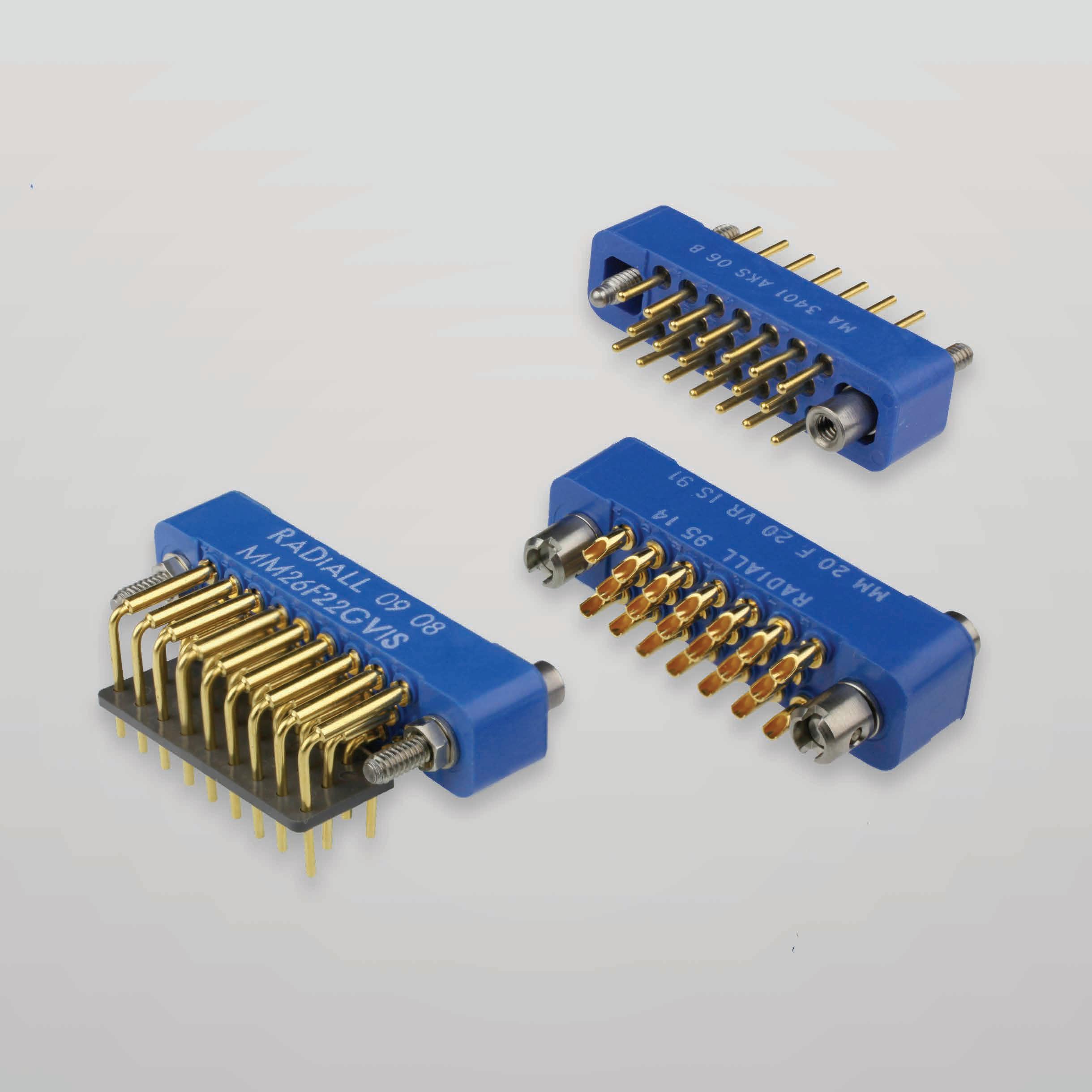
THE MM SERIES
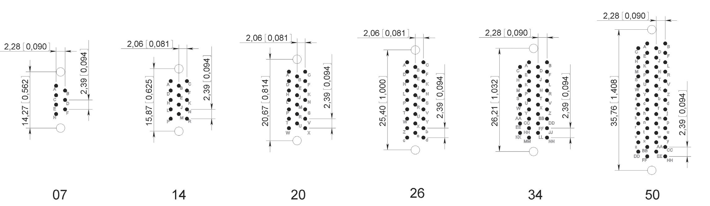
This series consists of six sizes of connectors with contact arrangements for 7, 14, 20, 26, 34 and 50 size 22 contacts Ø 0 76 mm / 0 030 inch
The series offers four types of terminations:
• Solder pot for wire (AWG 22 max)
• Straight solder pin for PBC
• Right angle solder pin for PBC
• Wire wrap
These connectors are fitted with rack guides or fixed or rotating jackscrews at each end. A protective covering for wire terminations can be installed on the connector�
THE MB SERIES
This series consists of twelve sizes of connectors with contact arrangements for 2, 3, 5, 11, 14, 20, 25, 34, 42, 50 and 75 size 20 contacts Ø 1 mm / 0 039 inch
The series offers three types of terminations:
• Solder pot for wire (AWG 20 max)
• Straight solder pin for PBC
• Right angle solder pin for PBC
These connectors are fitted with rack guides or fixed or rotating jackscrews at each end.
Wires and soldered terminations for wire can be protected by either top or side entry backshells or by potting covers for 2 to 14 contacts connectors
A range of top and side entry backshells with cable clamps in yellow anodized aluminium alloy are available� They are designed to protect the soldered wire connections, provide strain relief to the cable and facilitate the disengagement of the mated connectors
Fitted with threaded posts they are suitable for connectors fitted with rack guides or fixed jackscrews. When fitted with rotating jackscrew guides they are fixed to the connectors without guides and jackscrews.
For the MB series there are also thermoplastic covers for “potting” ensuring that the terminated wires at the back of the insulator are protected�
APPLICATIONS
Their mass and volume make them particularly suitable for the following applications: civil and military, in-flight equipment, instrumentation, missile, etc
Originally developed for rack and panel assemblies they can be adapted for cable to cable applications with cable clamp backshell

PRODUCT OVERVIEW
Detailed view of the various parts of the MM series connector�
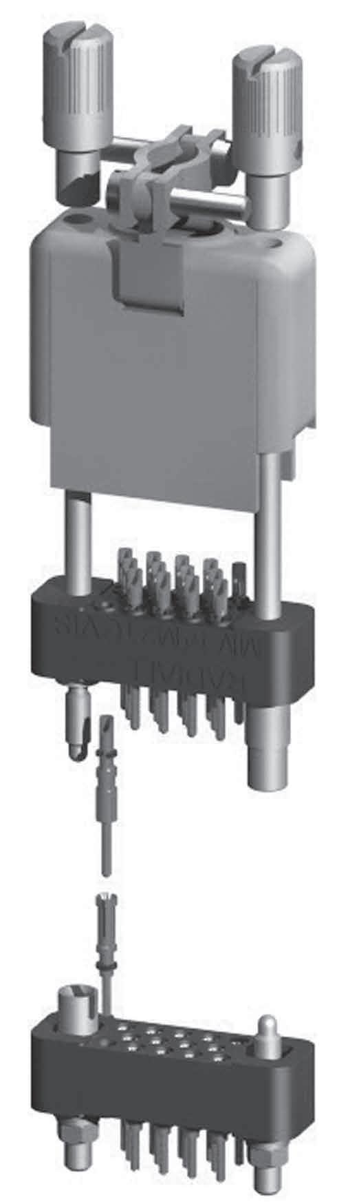
Contact for PCB
TECHNICAL CHARACTERISTICS
ELECTRICAL
Conforms to MIL-C-28748 performance requirements and UTE-C-93426 HE611 standard
• Current Rating: 5A
• Test Voltage at Sea Level: 1,000 Vrms/50 Hz
• Operating Voltage at Sea Level: 350 Vrms/50 Hz
• Operating Voltage at 70,000 ft: 90 Vrms/50 Hz
• Insulation Resistance: > 5,000 MΩ
• Contact Resistance: < 5 mΩ
MECHANICAL & ENVIRONMENTAL
Conforms to MIL-C-28748 performance requirements and UTE-C-93426 HE611 standard
• Temperature Range: -55 °C (-131 °F) to 125 °C (257 °F)
• Durability: 500 Mating Cycles
• Shock: 100g/6ms
• Vibration: 20g / 10-2000 Hz
• Humidity: 56 Days
• Contact Insertion Force: 3N
• Salt Spray: 48 Hours
MATERIALS
Insulator
Glass Filled Diallylphthalate Conform to MIL-M-14SDG-F
Pin Contact Copper Alloy
Socket Contact
Guides & Jackscrews
MASSES G (OZ)
Alloy
Steel
HOW TO ORDER CONNECTORS
SERIES
MM SERIES
Contact arrangement (refer to page 10-7)
07 - 14 - 20 - 26: 34: 50
CONTACT TYPE
M: Pin
F: Socket
TERMINATION STYLE (REFER TO PAGE 10-8)
20: Solder pot
21: Straight solder pin for PBC
22: Right angle solder pin for PBC
23: Wraping contact 1 wrap
24: Wraping contact 2 wrap
25: Wraping contact 3 wrap
GUIDES AND JACKSCREWS (REFER TO PAGE 10-11)
00: Without guides and jackscrews [1]
G3: Rack guides [2]
GV: Fixed jackscrews [2]
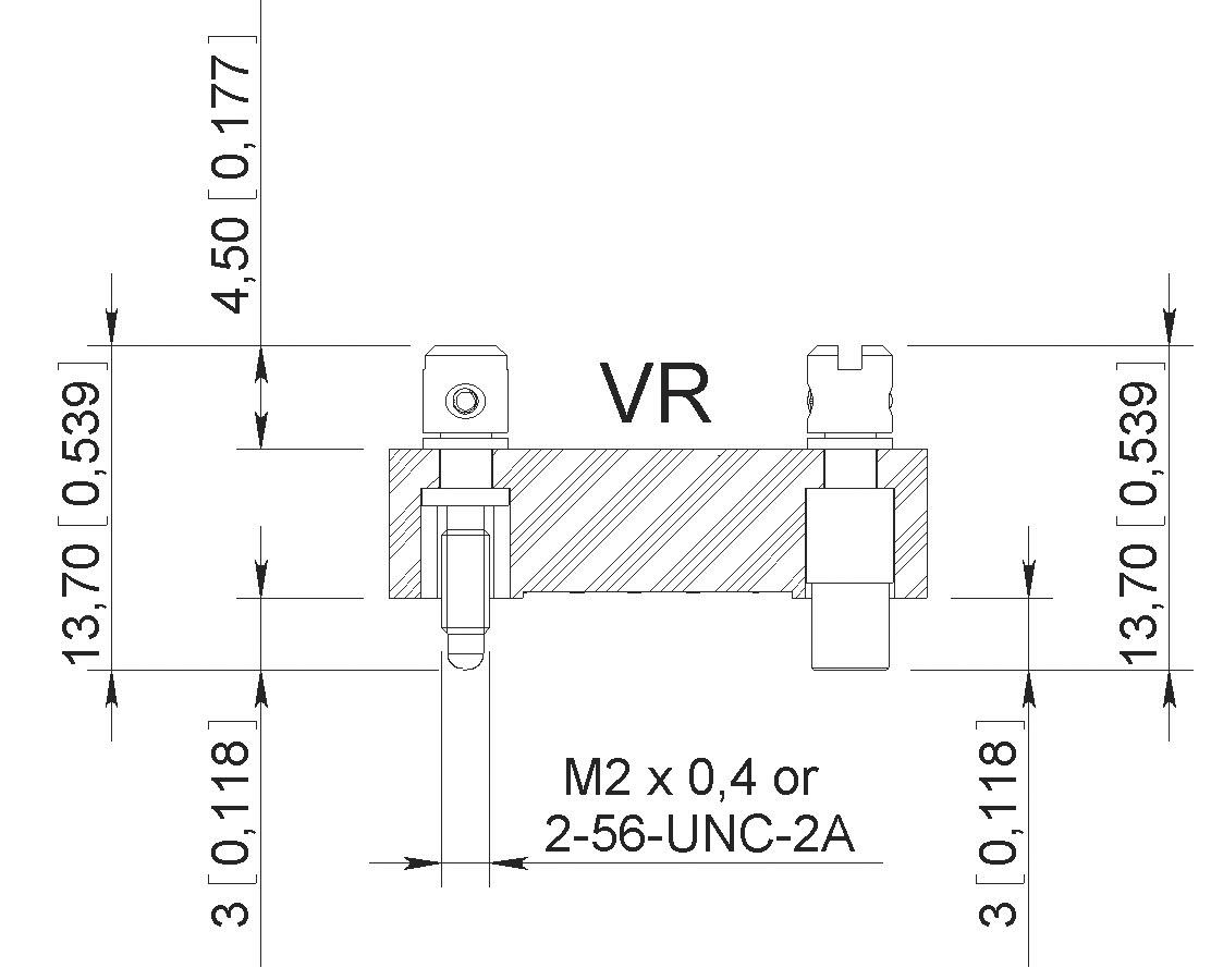
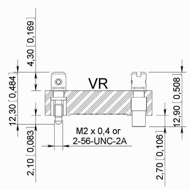
VR: Short rotating jackscrews
VL: Long rotating jackscrews [3]
THREAD, GUIDES OR JACKSCREWS
00: Without guides and jackscrews IS: ISO (M2 × 0 4) NC: 2-56 UNC
CONNECTOR IDENTIFICATION
The part number is printed on the insulator side
Notes
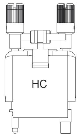
1. Connectors to be used with backshell HC (see page 10-13) and rotating jackscrews
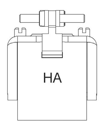
2. Connectors to be used with backshell HA (see page 10-13)
3. VL jackscrew assembly is not available for termination style type 22
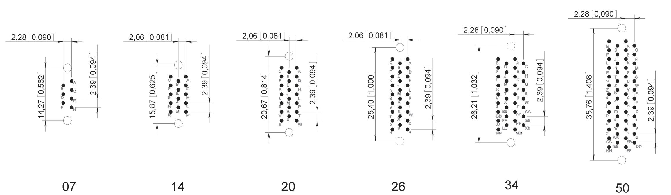
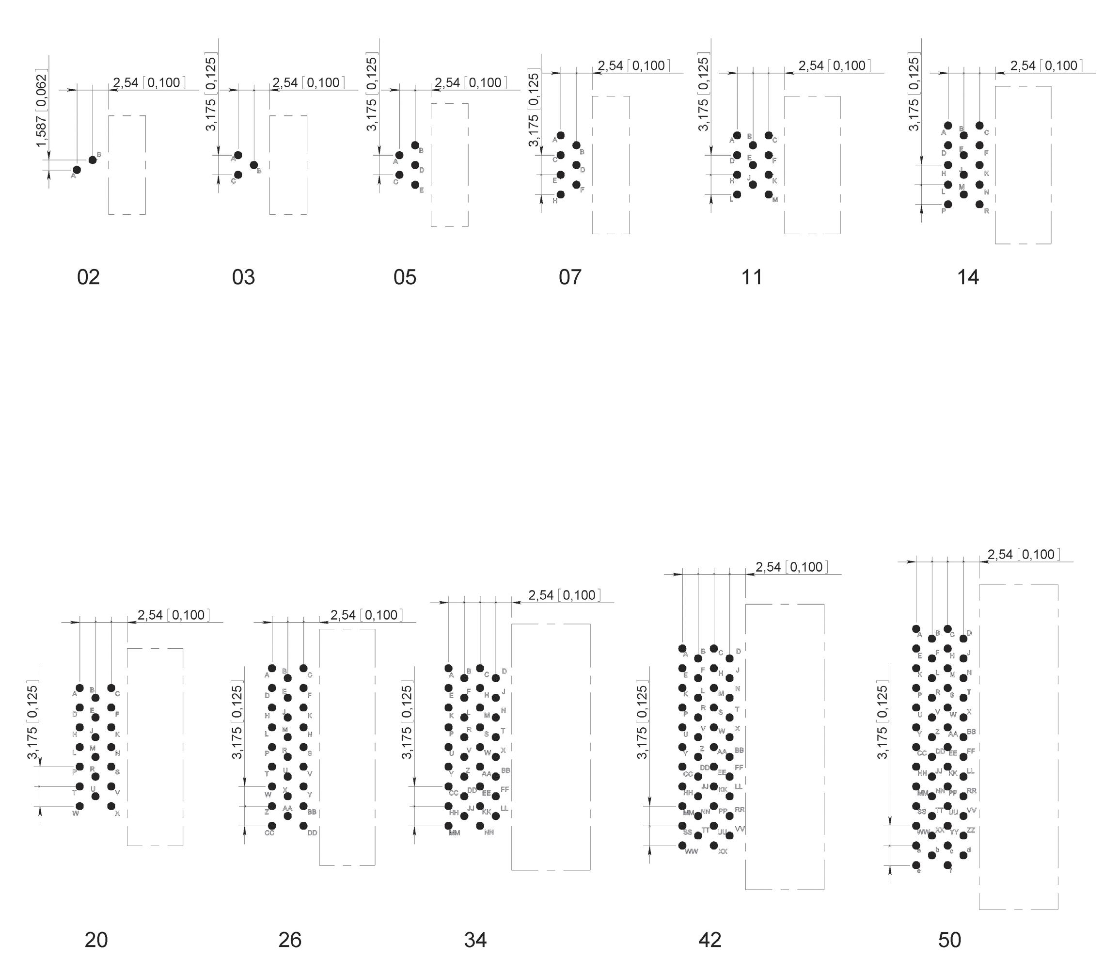
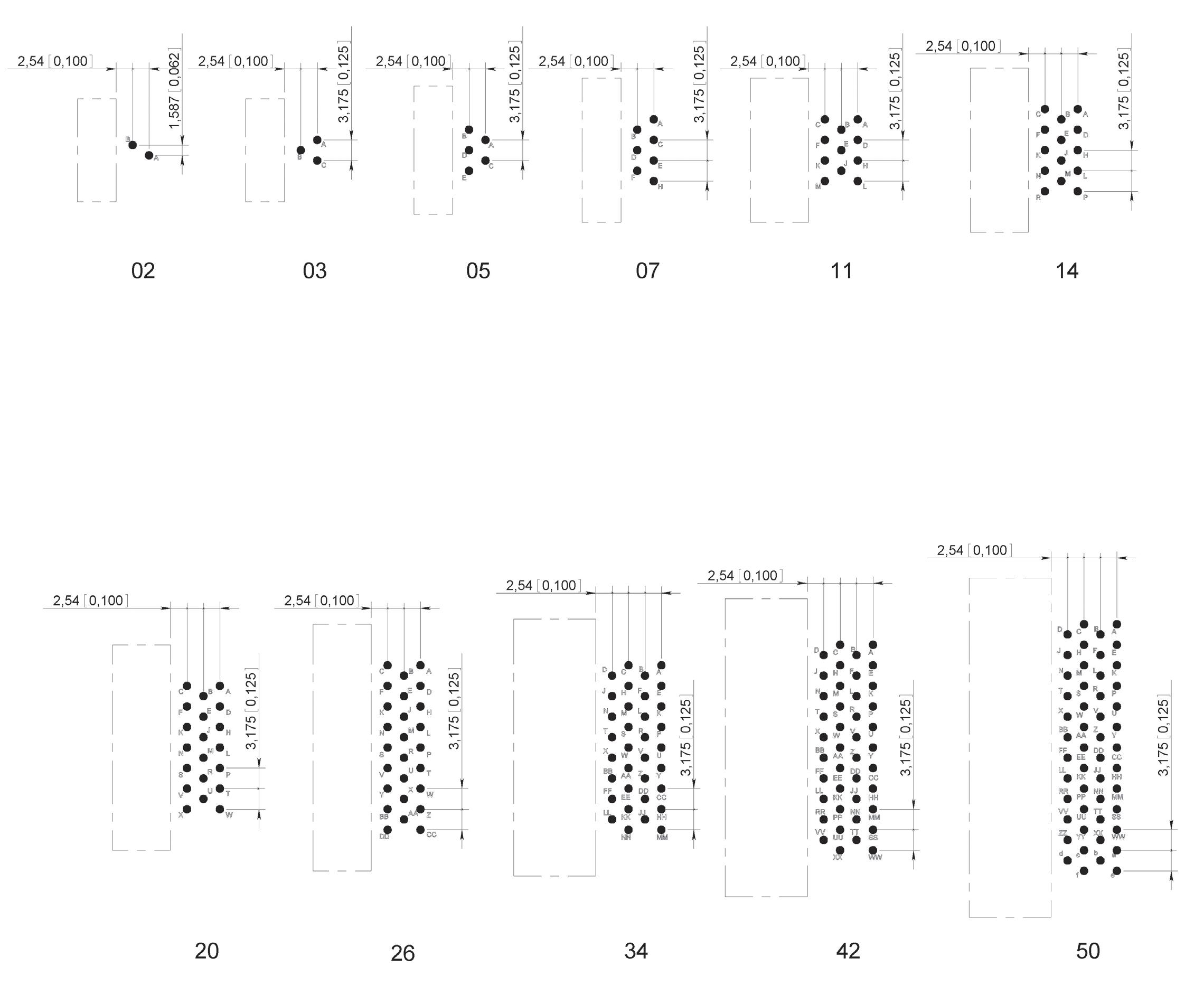
CONTACT ARRANGEMENTS
MALE CONNECTOR
WIRING SIDE DIMENSIONS MM (IN.)
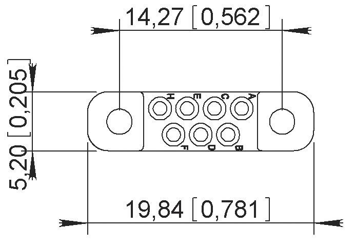
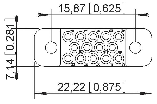
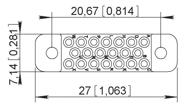
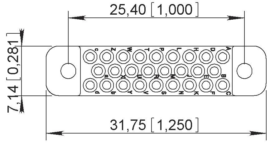
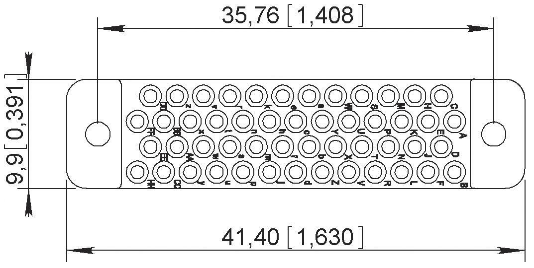
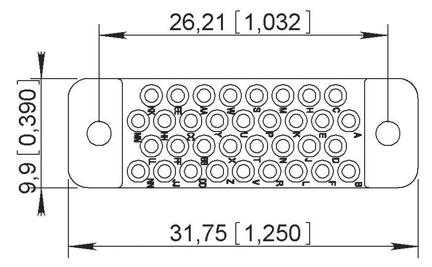
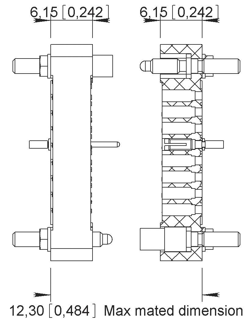
MATING DIMENSIONS
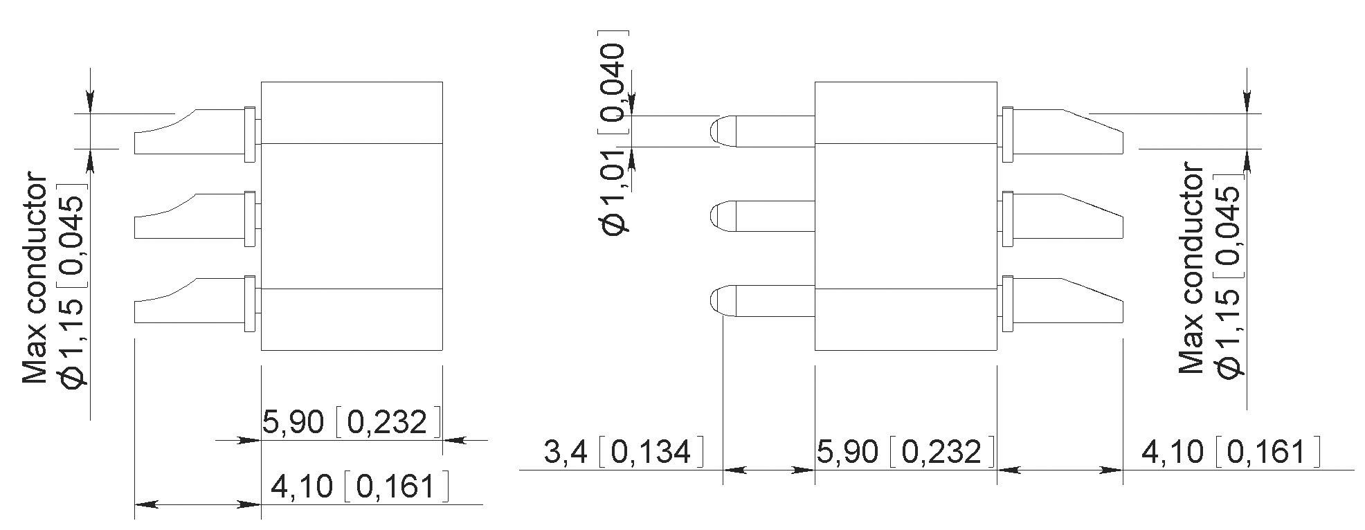
TERMINATION STYLES
TYPE 20
Solder pot
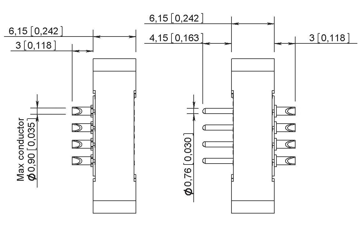
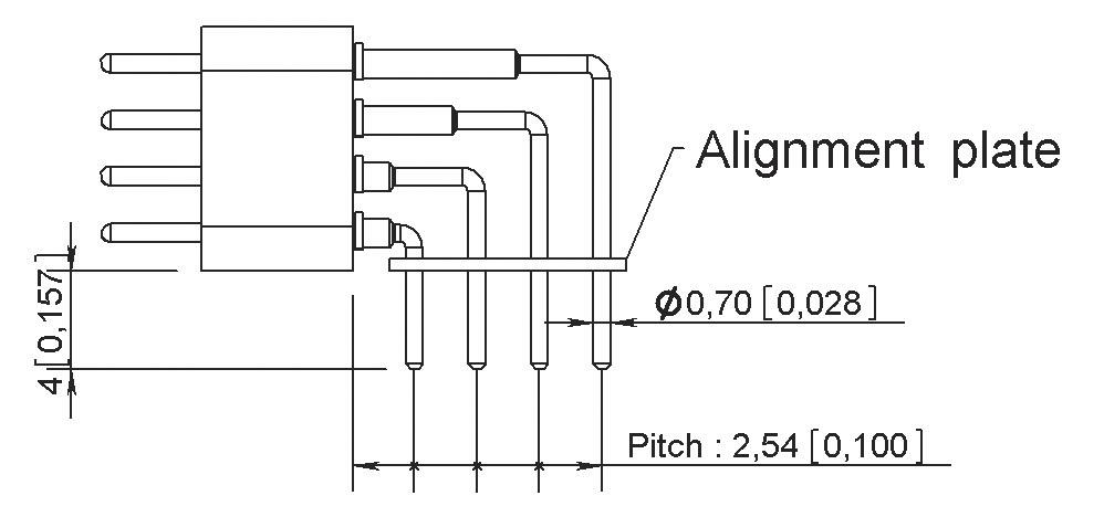
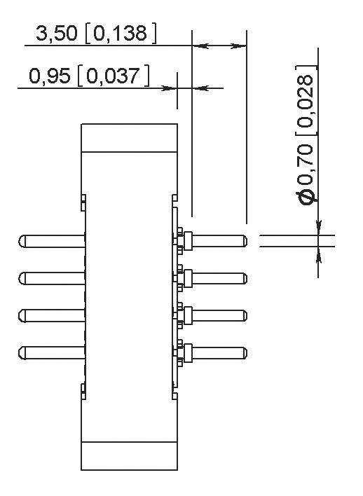
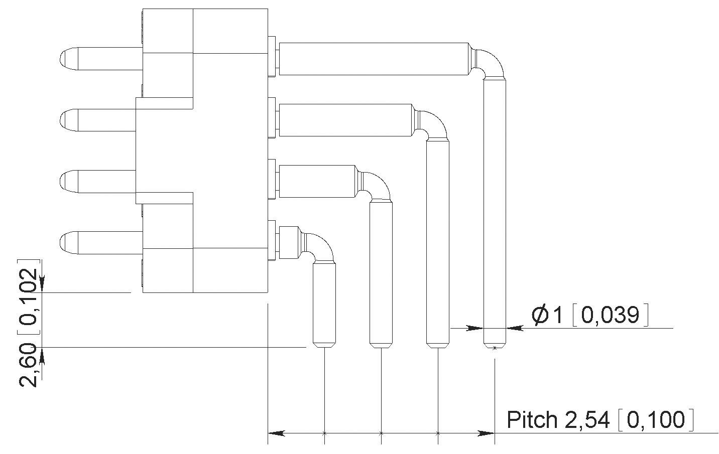
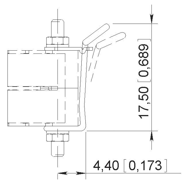
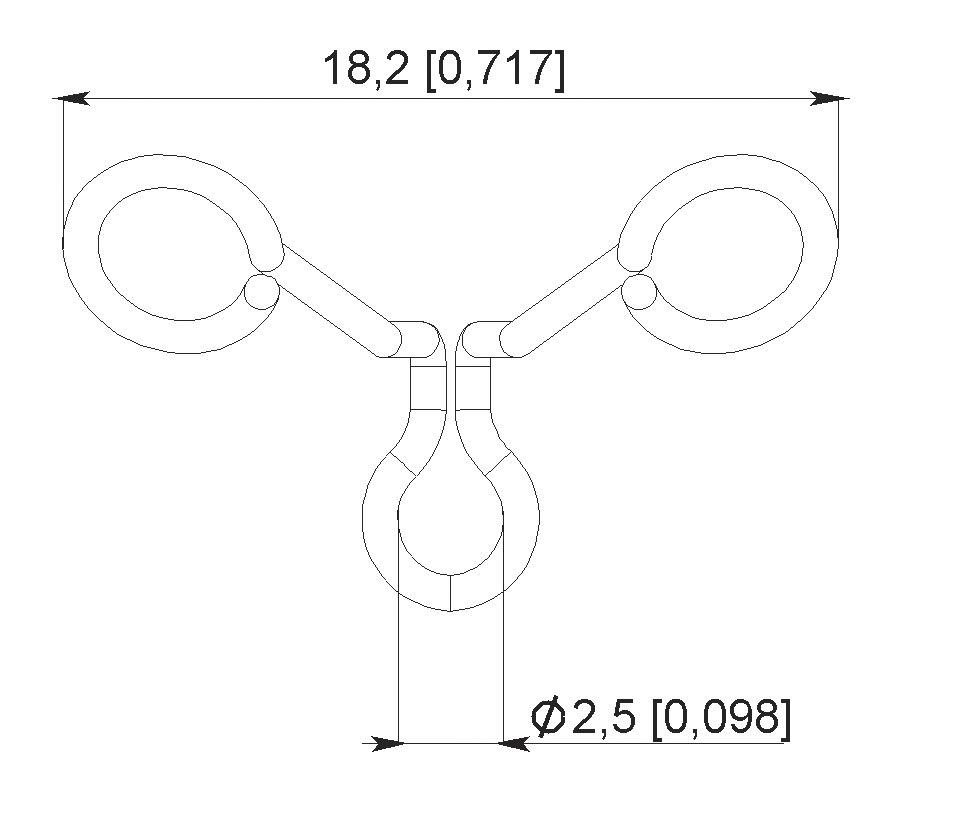
TYPE 22
Right angle solder pin for PCB
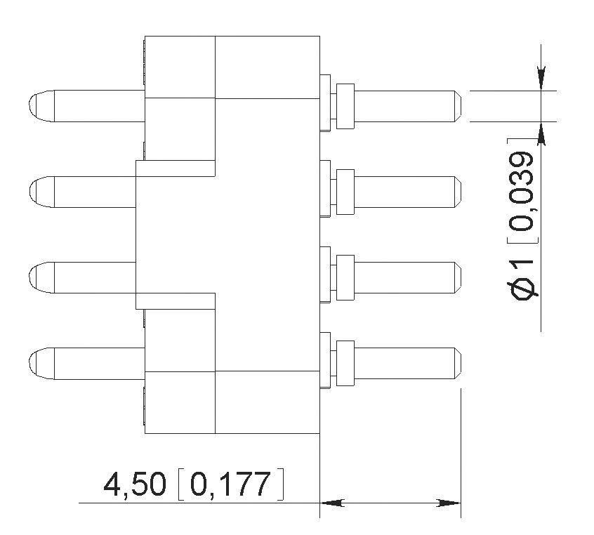
TYPE 21 [1]
Straight solder pin for PCB
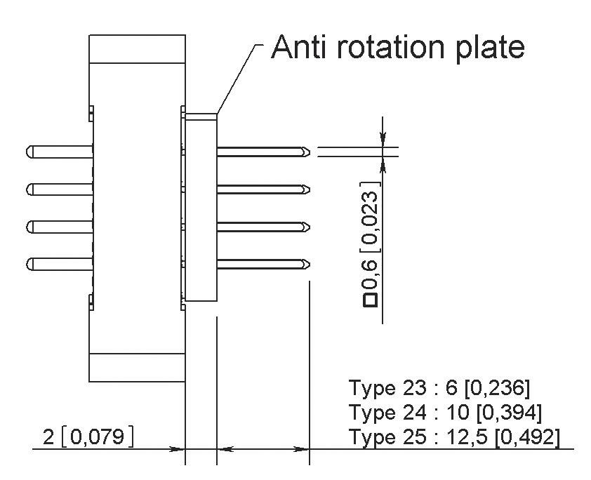
TYPE 23 - 24 - 25
23: Wire wrap termination (1 level)
24: Wire wrap termination (2 level)
25: Wire wrap termination (3 level)
Notes
Dimensions mm (inch)
1. For termination style type 21, the connectors are supplied with insulating washers in order to make space between the insulator and the PCB
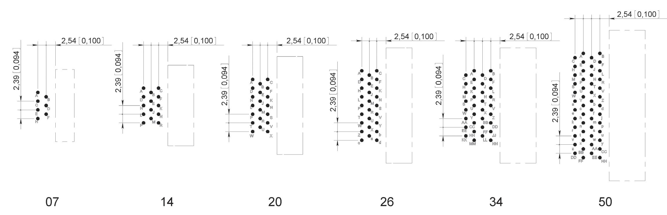
PRINTED CIRCUIT DRILL PATTERN
TYPE 21 TERMINATION STYLE - Connector with socket contacts
PCB COMPONENT SIDE VIEW
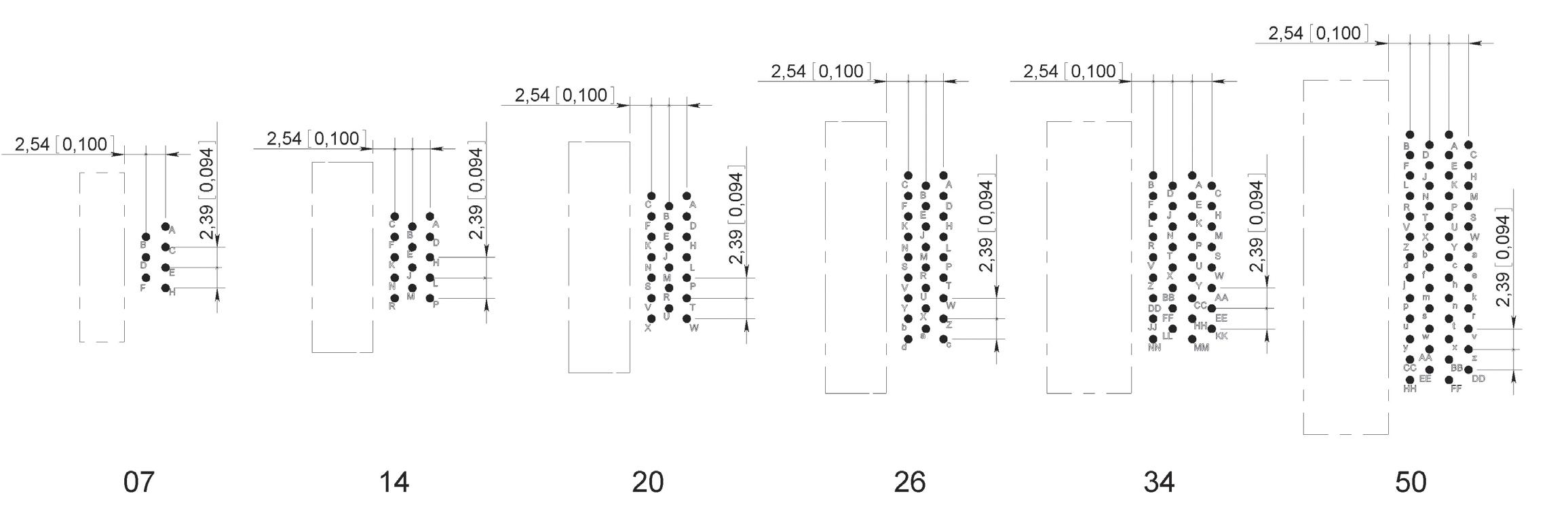
TYPE 21 TERMINATION STYLE - Connector with pin contacts
PCB COMPONENT SIDE VIEW
Notes
Printed circuit drilling 0.8 mm ±0.05 (0.031 ±0.002)
Drilling to fix the connector. Required for guides G3 and GV fixing only 2.2 mm (0.087) for ISO guides and 2.4 mm (0.094) for UNC guides
TYPE 22 TERMINATION STYLE - Connector with socket contacts
PCB COMPONENT SIDE VIEW
TYPE 22 TERMINATION STYLE - Connector with pin contacts
PCB COMPONENT SIDE VIEW
Notes:
•
GUIDES & JACKSCREWS MM Series
Stainless steel guides and jackscrews are supplied with either ISO (M2 x 0.4) or UNC (2-56 UNC) threads. The guides or jackscrews types (G3 – GV – VL – VR) and the type of thread (ISO or UNC) required are to be defined in the part number on page 10-6
The standard configuration of guides and jackscrews is:
• Male guide (or jackscrew) at the end nearest contact A of the female connector
• Female guide (or jackscrew) at the end nearest contact A of the male connector
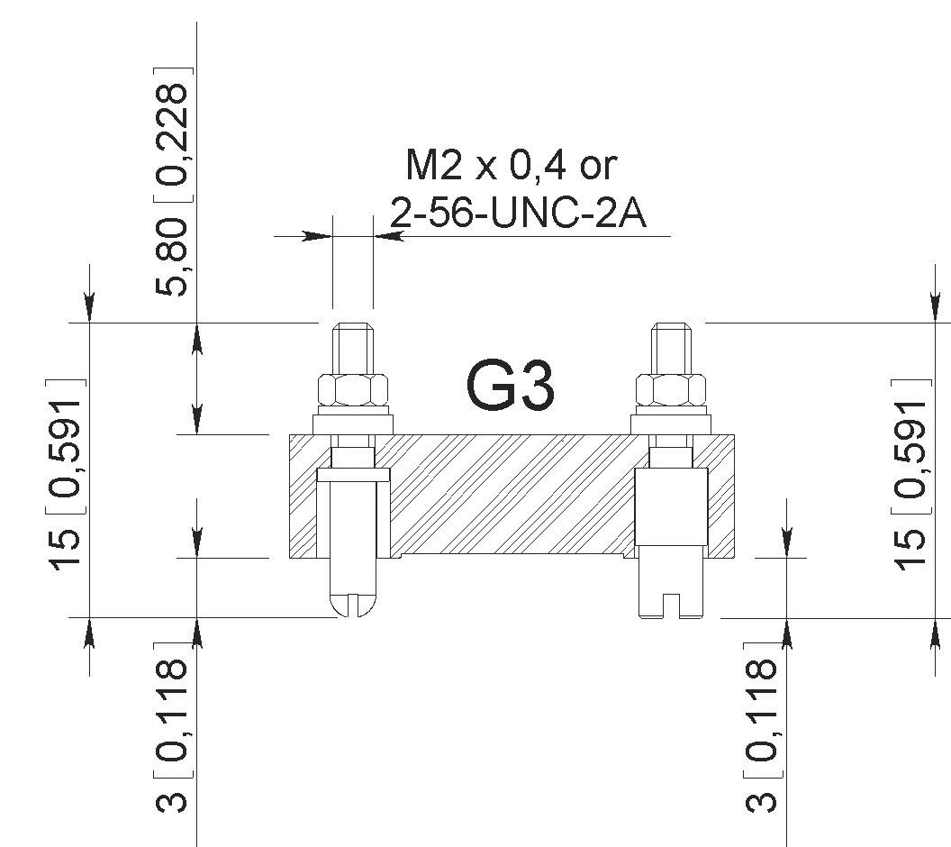
These guide and jackscrews can be used with backshell HA
LONG AND SHORT ROTATING JACKSCREWS TYPE VL – VR
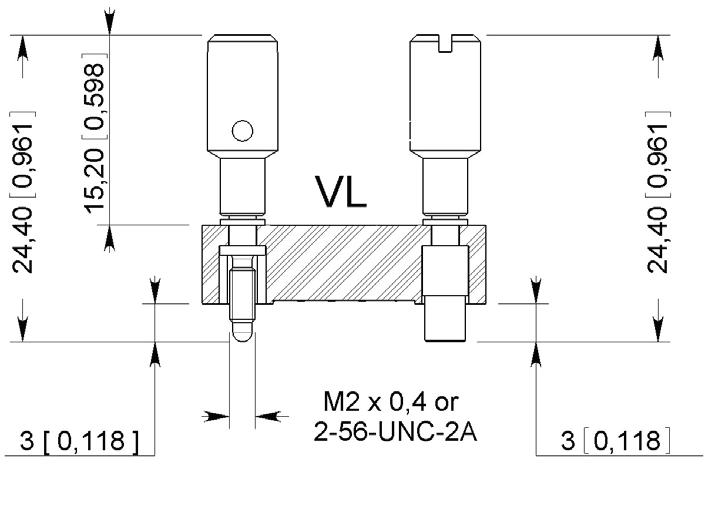
Mating torque: 0.2 Nm
Not available for termination style type 22 Cannot be used with any backshell
JACKSCREWS TYPE GV
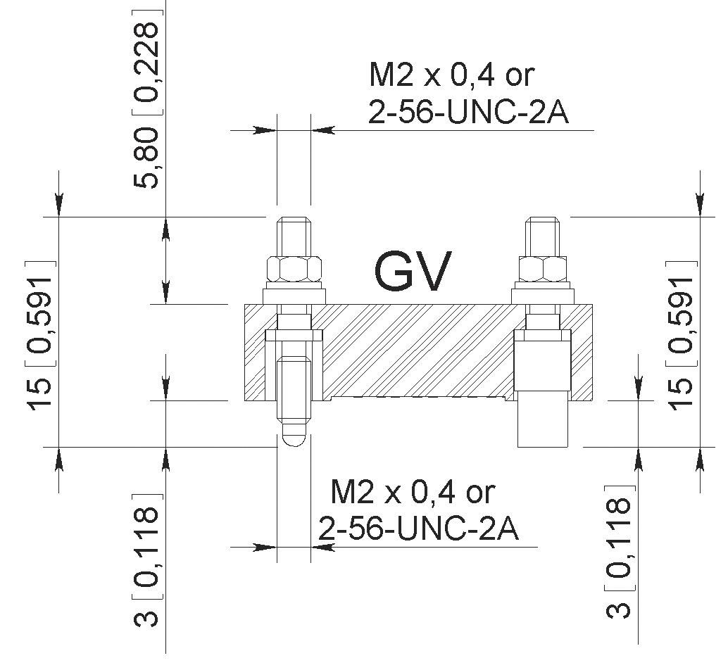
Mating torque: 0.2 Nm Cannot be used with any backshell
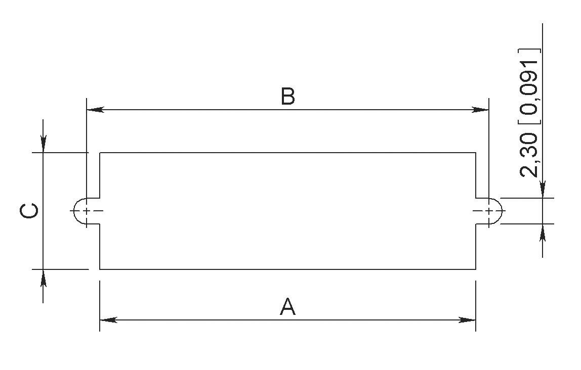
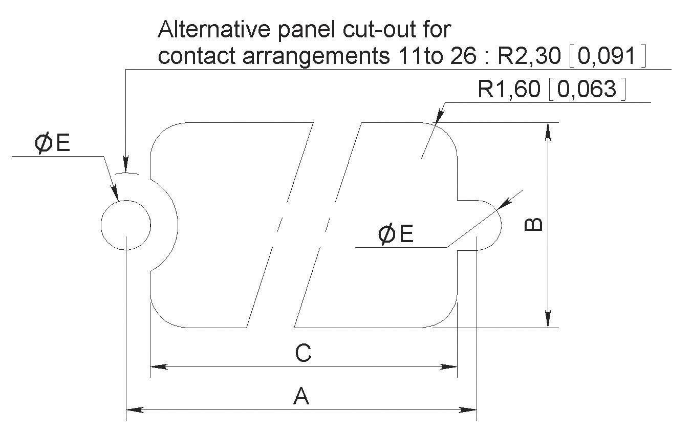
PANEL CUT-OUT
CONNECTOR MATING COMPATIBILITY
TERMINATION STYLE TYPE 20 ONLY – Use with backshell
BACKSHELL TYPE
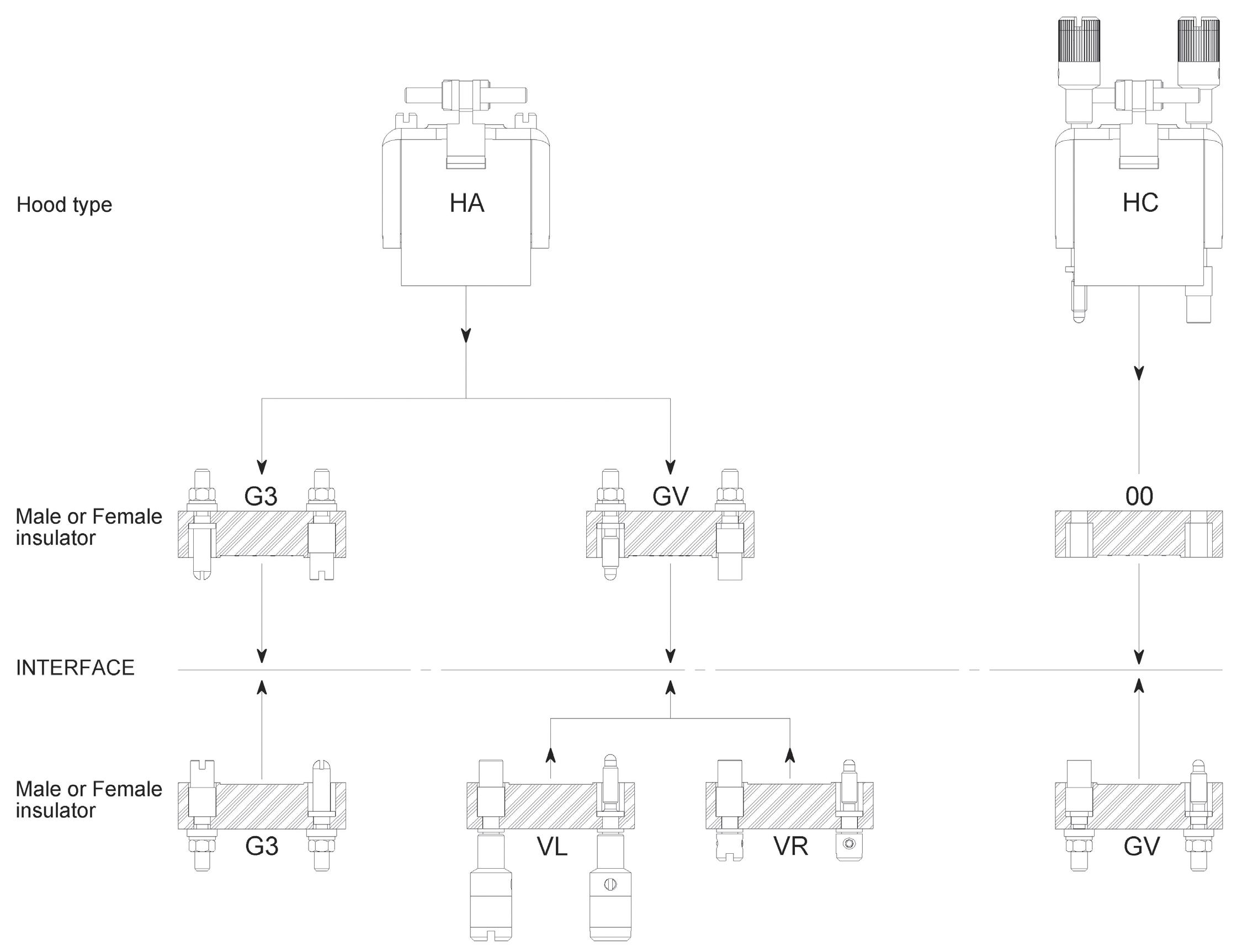
Use without backshell – All termination style type
BACKSHELL TYPE AVAILABILITY
Fixing of hoods only suitable for insulator with termination style type 20 (solder pot)
TOP ENTRY BACKSHELLS
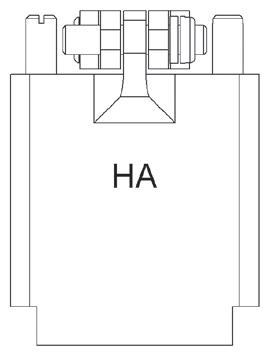
TYPE HA
Backshells supplied with two internal threaded posts which are screwed into the guides G3 or jackscrews GV
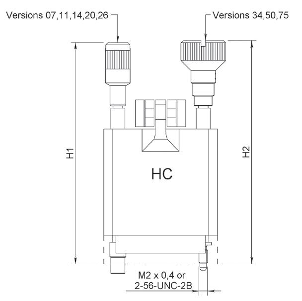
TYPE HC
Backshells supplied with two long rotating jackscrews These backshells are mounted on connectors without guides or jackscrews (code 00)
PART NUMBERS
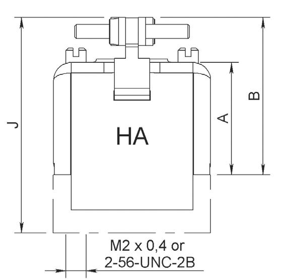
MATING TORQUE: 0.15 NM
Notes: Dimensions mm (inch)
Fixing of backshells only suitable for insulator with termination style type 20 (solder pot).
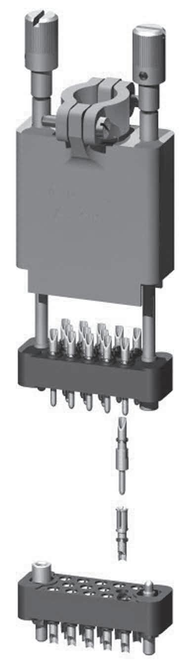
PRODUCT OVERVIEW
Detailed view of the various parts of the MB series connector�
TECHNICAL CHARACTERISTICS
ELECTRICAL
Conforms to MIL-C-28748 performance requirements standard�
• Current Rating: 7� 5A
• Test Voltage at Sea Level: 1,500 Vrms/50 Hz
• Operating Voltage at Sea Level: 500 Vrms/50 Hz
• Insulation Resistance: > 5,000 MΩ
• Contact Resistance: < 5 mΩ
MECHANICAL & ENVIRONMENTAL
• Temperature Range: -55 °C (-131 °F) to 125 °C (257 °F)
• Durability: 500 Mating Cycles
• Shock: 50g/11ms
• Vibration: 20 g/10-2,000 Hz
• Humidity: 21 Days
• Contact Insertion Force: 3 N
• Salt Spray: 48 Hours
MATERIALS
Insulator
Pin Contact
Socket Contact
Guides & Jackscrews
Backshells
Spring Lever Clamps
Glass Filled Diallylphthalate Conform to MIL-M-14SDG-F
Copper Alloy Gold over Nickel
Copper Alloy Gold over Nickel
Stainless Steel
Aluminium Alloy Yellow Anodized
Stainless Steel
Potting Moulds Nylon
MASSES G (OZ)
WEIGHT OF CONNECTORS MATED
Backshells & Jackscrew
HOW TO ORDER CONNECTORS
MB Series MM
SERIES
MB SERIES
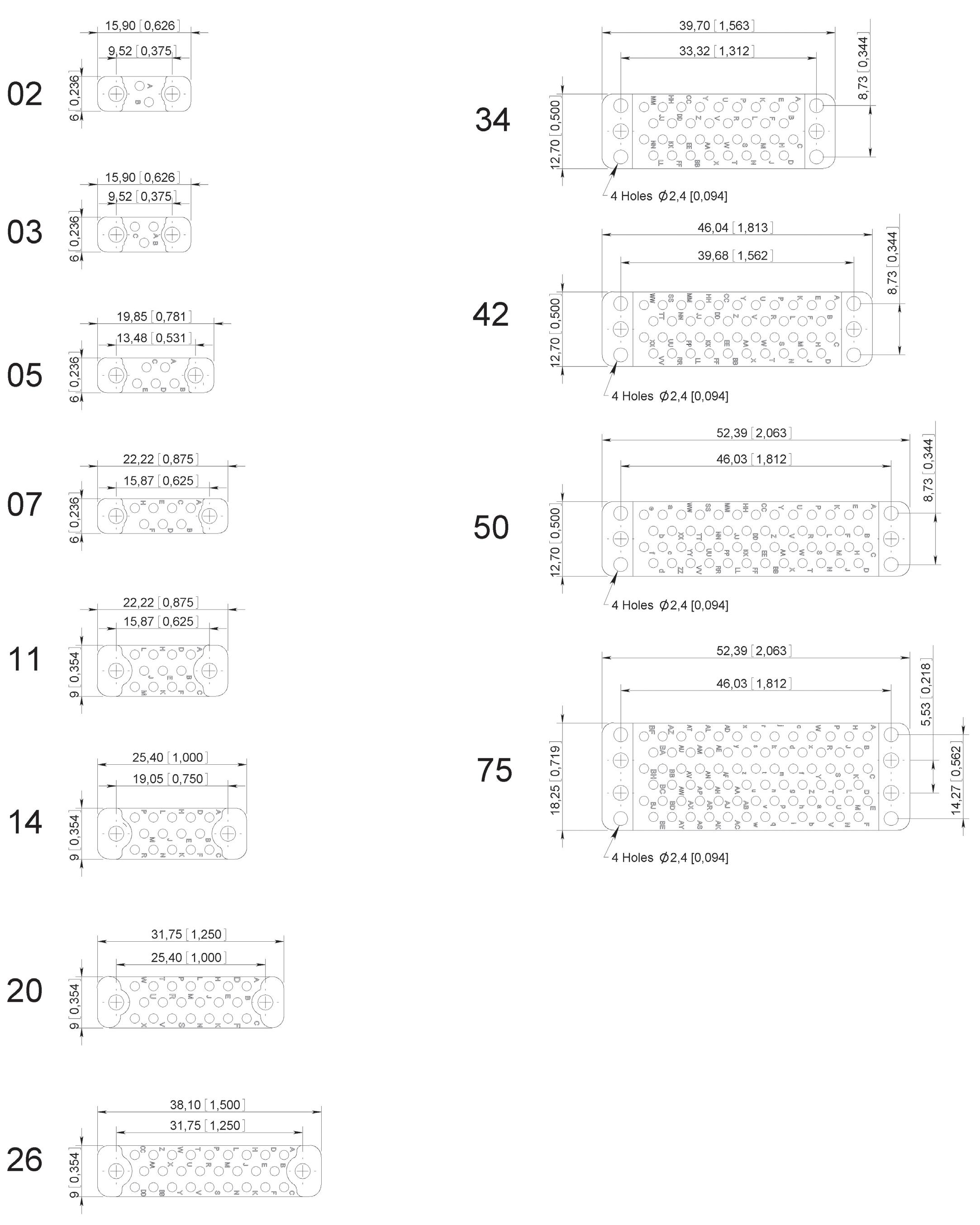
Contact arrangement (refer to page 10-18)
02: 03 : 05 : 07 - 11 - 14
20: 26 : 34 : 42 - 50 - 75
CONTACT TYPE
M: Pin
F: Socket
TERMINATION STYLE (REFER TO PAGE 10-19)
85: Solder pot
86: Straight solder pin for PCB
87: Right angle solder pin for PCB
GUIDES AND JACKSCREWS (REFER TO PAGE 10-25)
00: Without guides and jackscrews [1]
G1: Rack guides [2]
GV: Fixed jackscrews [2]
VR: Short rotating jackscrews
VL: Long rotating jackscrews [3]
SHIPMENT WITHOUT BACKSHELL AND ACCESSORIES
THREAD, GUIDES OR JACKSCREWS
00: Without guides and jackscrews IS: ISO (M2 x 0.4)
NC: 2-56 UNC
Notes:
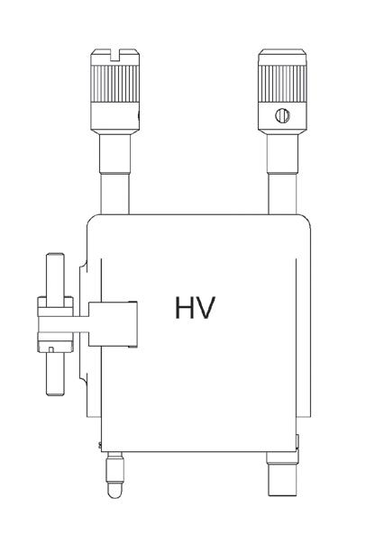
1. Connectors to be used with backshell HC and HV (see page 10-26) or rack guides G1
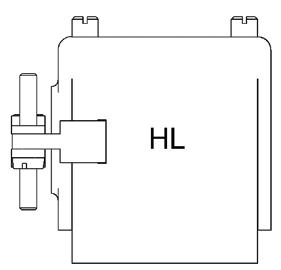
2. Connectors to be used with backshell HA and HL (see page 10-26) A spring clip locking system can be fitted (see page 10-30)
3. VL jackscrews assembly is only available for termination style type 85

MB Series
TERMINATION STYLES
All contacts arrangement and termination style have contacts stopped in rotation (except contact arrangements 42, 50 and 75 for these please contact us)�
TYPE 85
Solder pot
TYPE 87
Right angle solder pin for PCB
TYPE 86 [1]
Straight solder pin for PCB
Notes
Dimensions mm (inch)
1. The connectors are supplied with insulating washers wich act as spacers between the insulator and the PCB
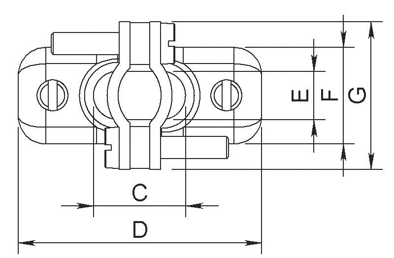
PANEL CUT-OUT
DIMENSIONS
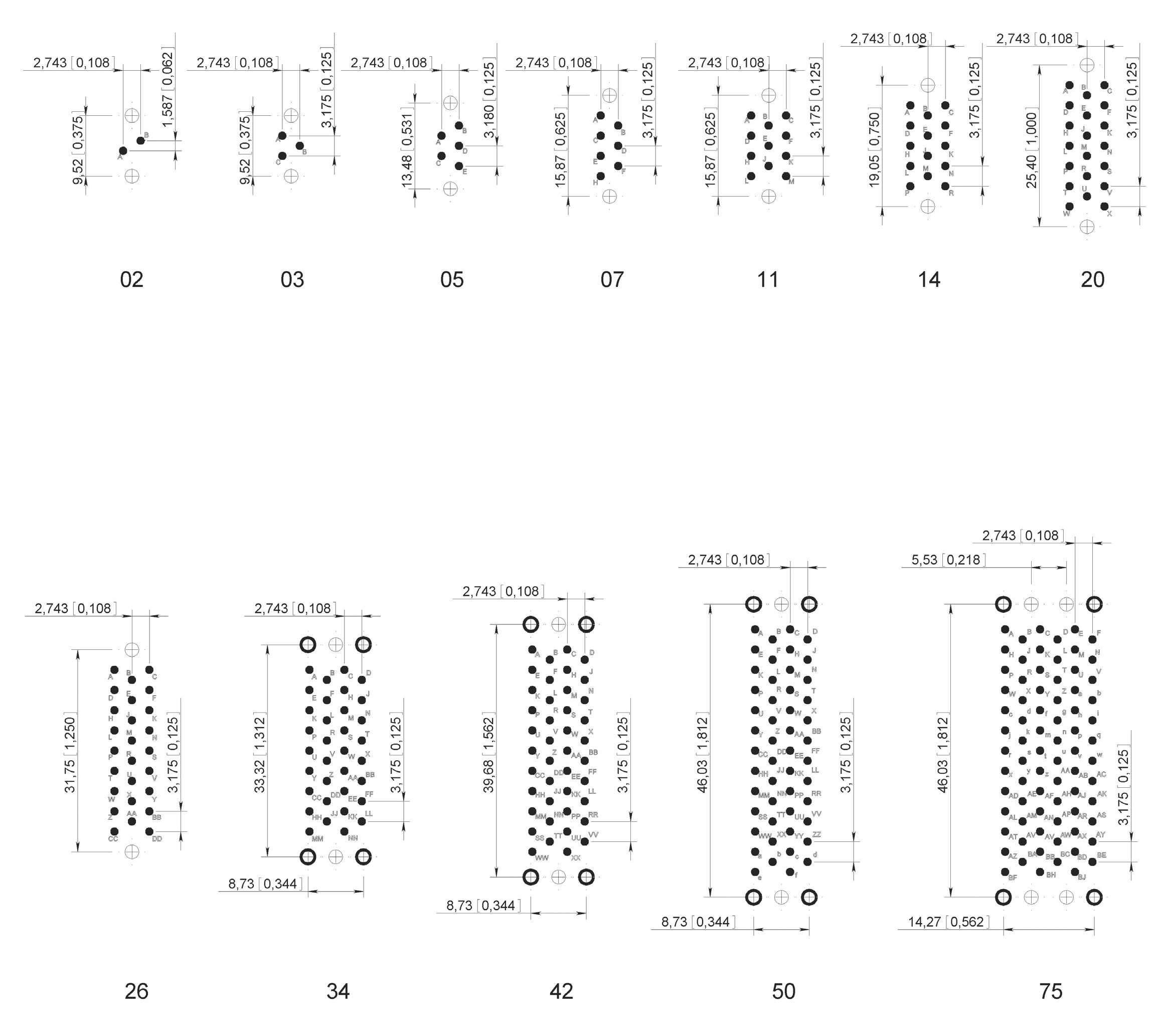
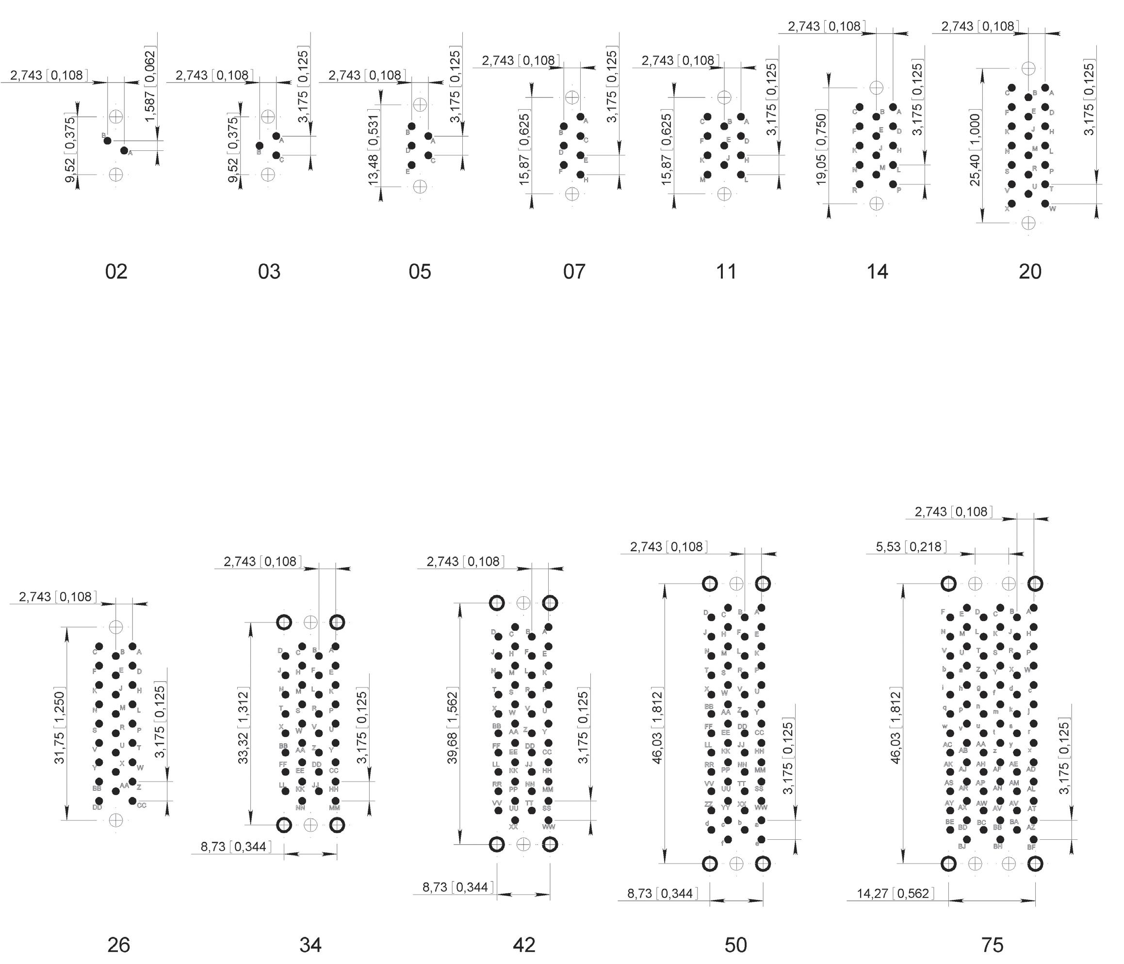
CONTACT ARRANGEMENTS 02 - 03 - 05 - 07 - 11 - 14 - 20 - 26
CONTACT ARRANGEMENTS 34 - 42 - 50 CONTACT ARRANGEMENT 75
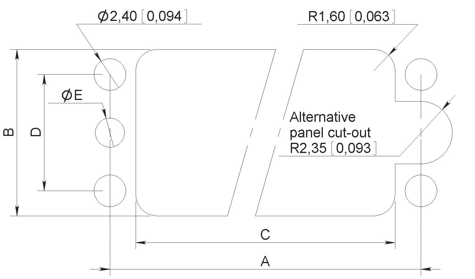
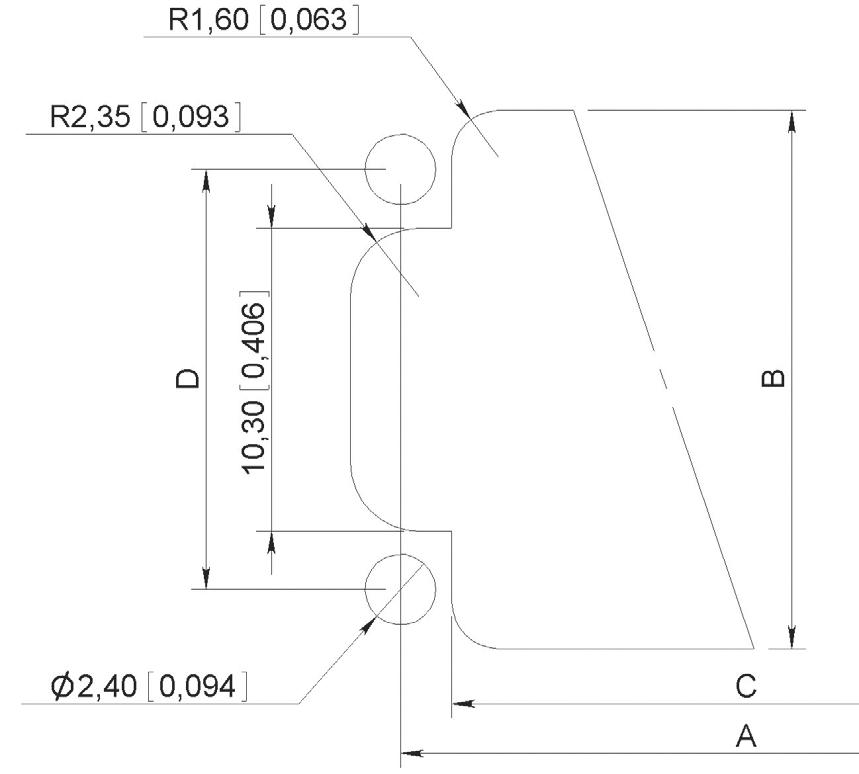
Notes
Dimensions mm (inch)
MB Series
PRINTED CIRCUIT DRILL PATTERN
TYPE 86 TERMINATION STYLE -
Notes:
Printed circuit drilling Ø 1.1 +0.1 (0.043 +0.003)
Drilling to fix the connector Ø 2.4 (0.094)
Drilling to fix the connector. Required for guides G1 and GV fixing only:
2.2 (0.087) Ø for ISO guides
2.4 (0.094) Ø for UNC guides
TYPE 86 TERMINATION STYLE - Connector with PIN contacts – PCB component side view in mm (inch)
Notes:
Printed circuit drilling Ø 1.1 +0.1 (0.043 +0.003)
Drilling to fix the connector Ø 2.4 (0.094)
Drilling to fix the connector. Required for guides G1 and GV fixing only:
2.2 (0.087) Ø for ISO guides
2.4 (0.094) Ø for UNC guides
TYPE 87 TERMINATION STYLE - Connector with PIN contacts – PCB component side view in mm (inch)
MB Series
GUIDES & JACKSCREWS
Stainless steel guides and jackscrews are supplied with either ISO (M2 x 0.4) or UNC (2-56 UNC) threads. The guides or jackscrews types G1 – GV – VL and VR and type of thread (ISO or UNC) required are to be defined in the part number on page 10-17
The standard configuration of guides and jackscrews is:
• Male guide (or jackscrew) at the end nearest contact A of the female connector
• Female guide (or jackscrew) at the end nearest contact A of the male connector
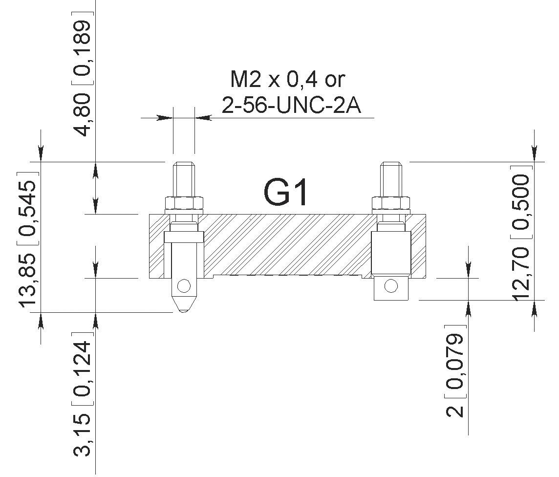
GUIDES TYPE G1
JACKSCREWS TYPE GV
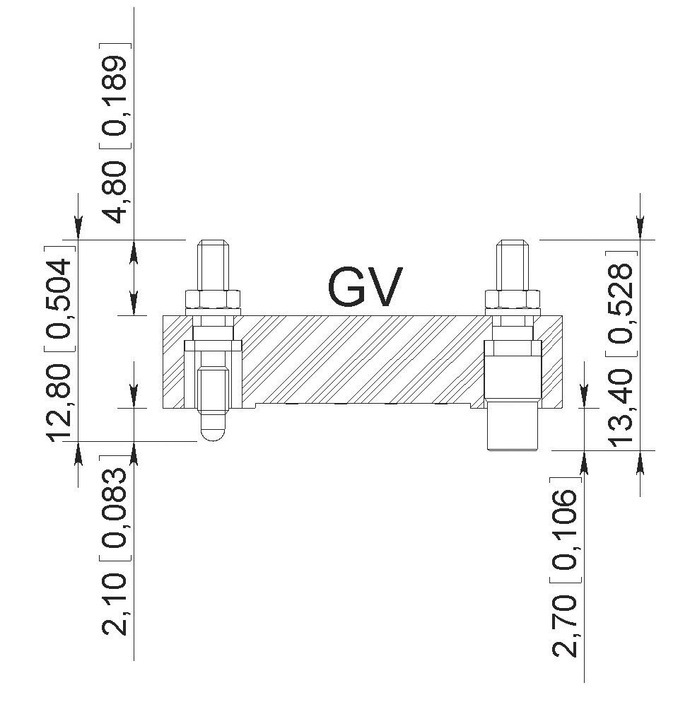
The 2,3, 5 and 7 way GV jackscrews are held securely in place by two flats on the jackscrews whereas the jackscrews for the other contact arrangements have a square section to avoid rotation
These guide and jackscrews can be used with backshells HA and HL
AND SHORT ROTATING JACKSCREWS TYPE VL – VR
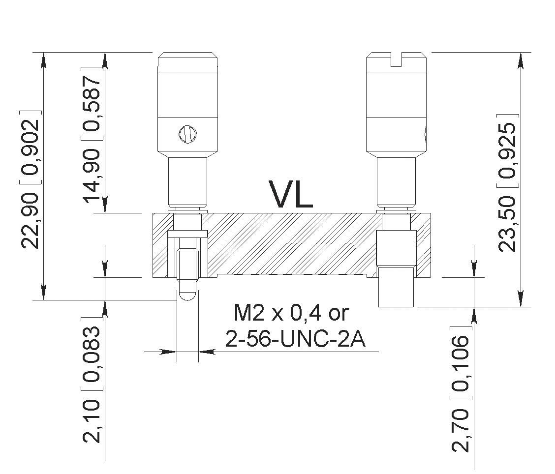
Mating torque: 0.2 Nm
Not available for termination style type 87
Cannot be used with backshell
Mating torque: 0.2 Nm Cannot be used with backshell
MB Series
CONNECTOR MATING COMPATIBILITY
TERMINATION STYLE TYPE 85 ONLY – Use with backshell
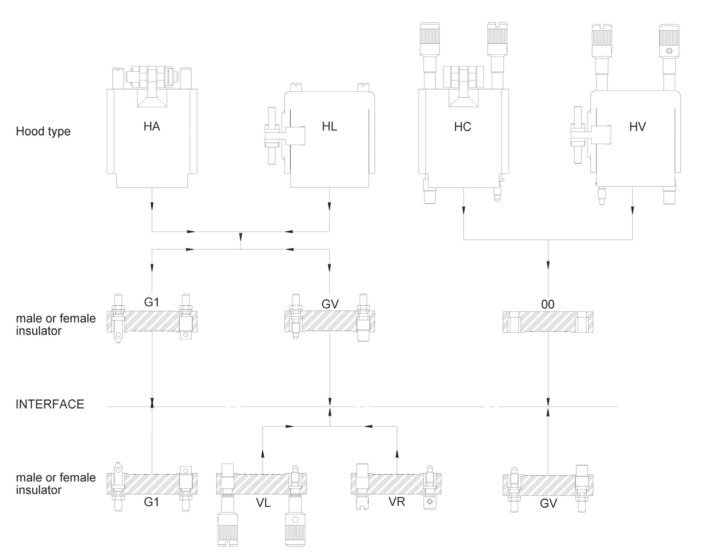
Use without backshell – All termination style type
MB Series
BACKSHELL TYPE AVAILABILITY
Fixing of backshells only suitable for insulator with termination style type 85 (solder pot)
Notes 1. Available for male contact arrangement only
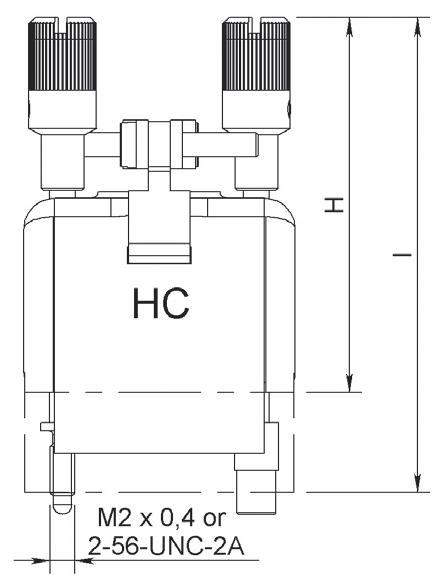
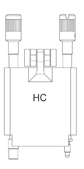
TOP ENTRY BACKSHELLS
TYPE HA
Backshells supplied with two internal threaded posts which are screwed into the guides G1 or jackscrews GV�
TYPE HC
Backshells supplied with two long rotating jackscrews These backshells are mounted on connectors without guides or jackscrews �
PART NUMBERS

Notes
Dimensions mm (inch)
1. Fixing of backshells only suitable for insulator with termination style type 85 (solder pot)
2. Backshells 34, 50 and 75 are fitted with 4 screws to be fixed to the connector block
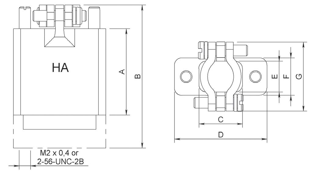
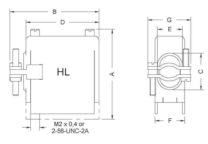
SIDE ENTRY BACKSHELLS
TYPE HA
Backshells supplied with two internal threaded posts which are screwed into the guides G1 or jackscrews GV�
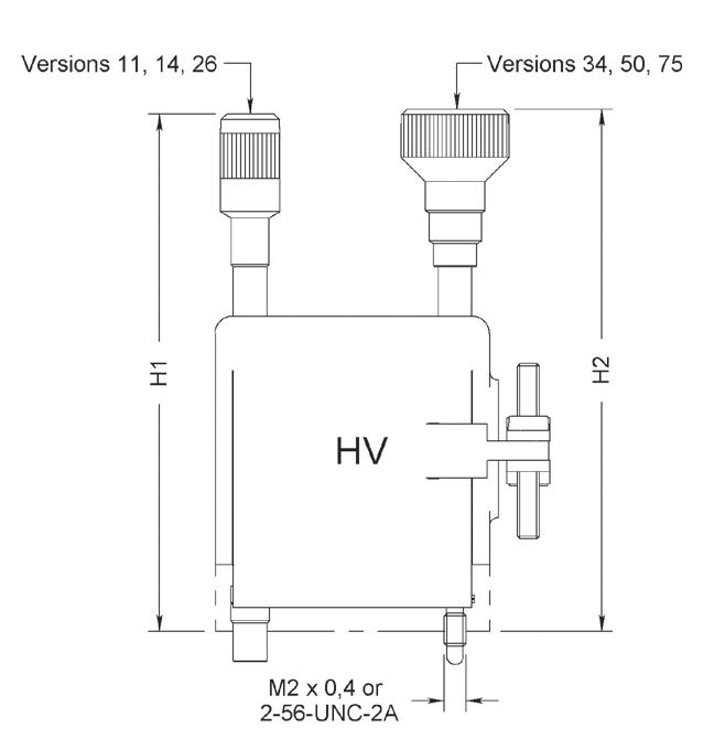
TYPE HC
Backshells supplied with two long rotating jackscrews These backshells are mounted on connectors without guides or jackscrews
PART NUMBERS
CONTACTS
Notes
Dimensions mm (inch)
1. Available for male contact arrangement only
2. Fixing of backshells only suitable for insulator with termination style type 85 (solder pot)
3. Backshells 34, 50 and 75 are fitted with 4 screws to be fixed to the connector block
ACCESSORIES
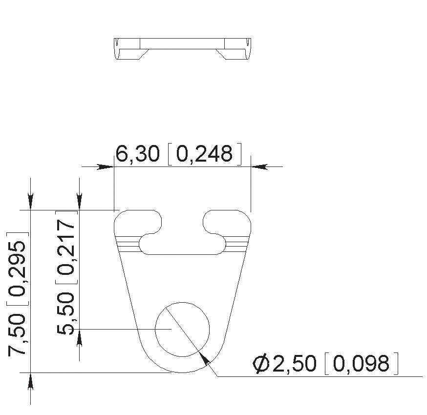
SPRING LOCKING SYSTEM
This simple locking system avoids accidental disconnection of connectors fitted to equipment which may be subjected to severe vibration. This system can be used where connector fitted with G1 guides are used with or without backshell
Part number of a pair: 624895
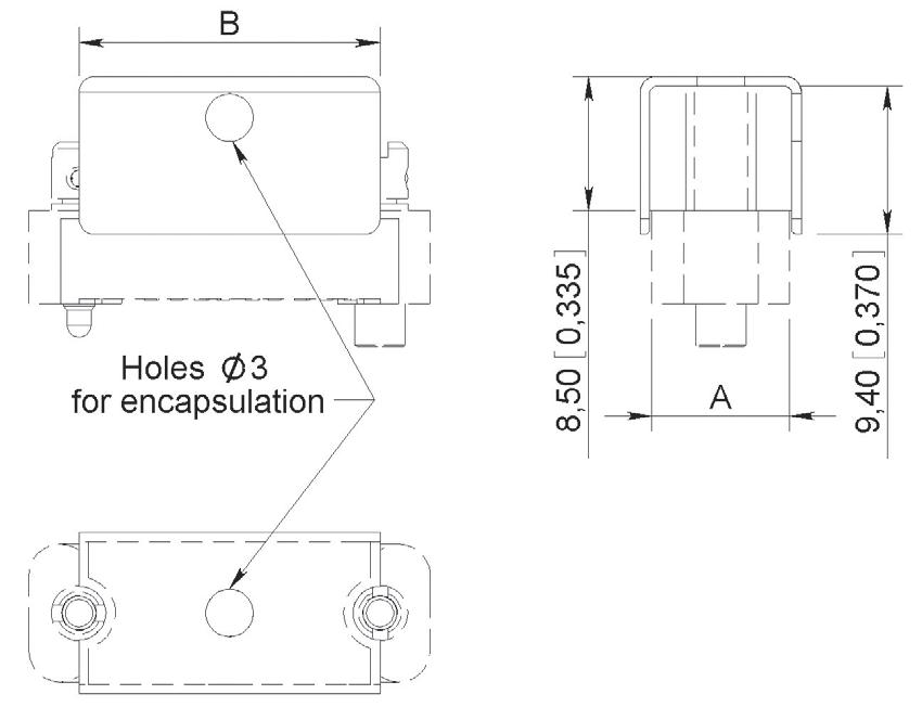
POTTING MOULDS
The plastic potting moulds are designed to fit onto the wiring side of the connectors in order so that the wiring and back end can be encapsulated. They can be used with connectors fitted with G1 guides and GV and VR jackscrews.