


Section 6 Table of Contents
RAMSES SERIES
LOW PIM PART NUMBER SELECTION GUIDE [1]
RAMSES SPnT R573LP 1 4 - 2/3/4/5/8/9 0/1 2 3 4/6
Notes
Example of P/N: R573423600LP is a SP6T SMA 18 GHz, latching, 28 Vdc, without option, solder pins. 1. For part number creation and available options, see detailed part number selection for each series.
RAMSES Series
SPDT LOW PIM UP TO 18 GHz

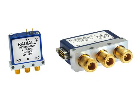
To meet growing market demands created by the deployment of 4G/LTE networks, Radiall has introduced a new range of Low PIM switches. RAMSES SPDT Low PIM switches are perfectly suited for RF test systems and test benches requiring excellent passive intermodulation performance up to 18 GHz; with a guarantee PIM performance of -160 dBc at +43 dBm over a life span of 2 million switching cycles. These products are specific to instrumentation and telecommunication applications �
Example of P/N: R570413030LP is a SPDT Low PIM SMA 18 GHz, failsafe, 28 Vdc, with supression diodes, solder pins.
PART NUMBER SELECTION
SERIES PREFIX
FREQUENCY RANGE
1: N up to 12 4 GHz
4: SMA up to 18 GHz
TYPE
1: Failsafe
2: Failsafe + I C
3: Latching
4: Latching + I.C.
5: Latching + S.C.O. [1]
6: Latching + S.C.O. + I.C. [1]
ACTUATOR VOLTAGE
2: 12 Vdc
3: 28 Vdc
TTL OPTION
0: Without TTL driver
1: With TTL driver [1 & 3]
OPTIONS [5]
0: Without option
1: Positive common [2]
3: With suppression diodes
4: With suppression diodes and positive common [2]
ACTUATOR TERMINALS
0: Solder pins
5: D-Sub connector [4]
Notes
I.C.: Indicator contact - S.C.O.: Self Cut-Off
1. Suppression diodes are already included in Self Cut-OFF & TTL option
2. Positive common shall be specified only with type 3, 4, 5 & 6 because failsafe models can be used with both polarities
3. Polarity is not relevant to application for switches with TTL driver
4. Only available for N models
RAMSES Series
GENERAL SPECIFICATIONS
Average power
See Power Rating Chart on page 1-16
Indicator rating 1 Watt/30 Volts/100 mA
Switching time ms 15 ms
Life (Min) 2 million cycles
Connectors
Actuator terminals
SMA - N
Solder pins or male 25 pin D-Sub connector
Operating temperature range -40°C to +85°C
Storage temperature range -55°C to +85°C
Vibration (MIL STD 202, method 204D, cond D) 10 - 2,000 Hz - 20 g
Shock (MIL STD 202, method 213B, cond C)
Reset: supply voltage time 1 sec. max./duty cycle 10%
RF PERFORMANCE
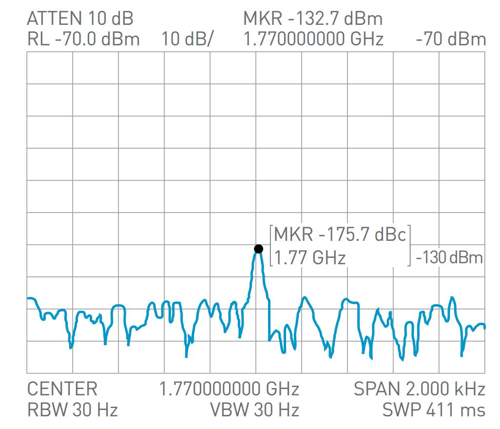
PASSIVE INTERMODULATION
TONE 1 1,810 MHz, approximately 43 dBm
TONE 2 1,850 MHz, approximately 43 dBm
3RD ORDER PIM 160 dBc at 1,770 MHz
Depending on application, carrier powers and frequencies — PIM measurements can vary. PIM testing is not measured during product acceptance test.
OUTSTANDING PIM PERFORMANCE

RAMSES Series
TYPICAL RF PERFORMANCE
Example: SPDT N up to 12.4 GHz
INSERTION LOSS & ISOLATION
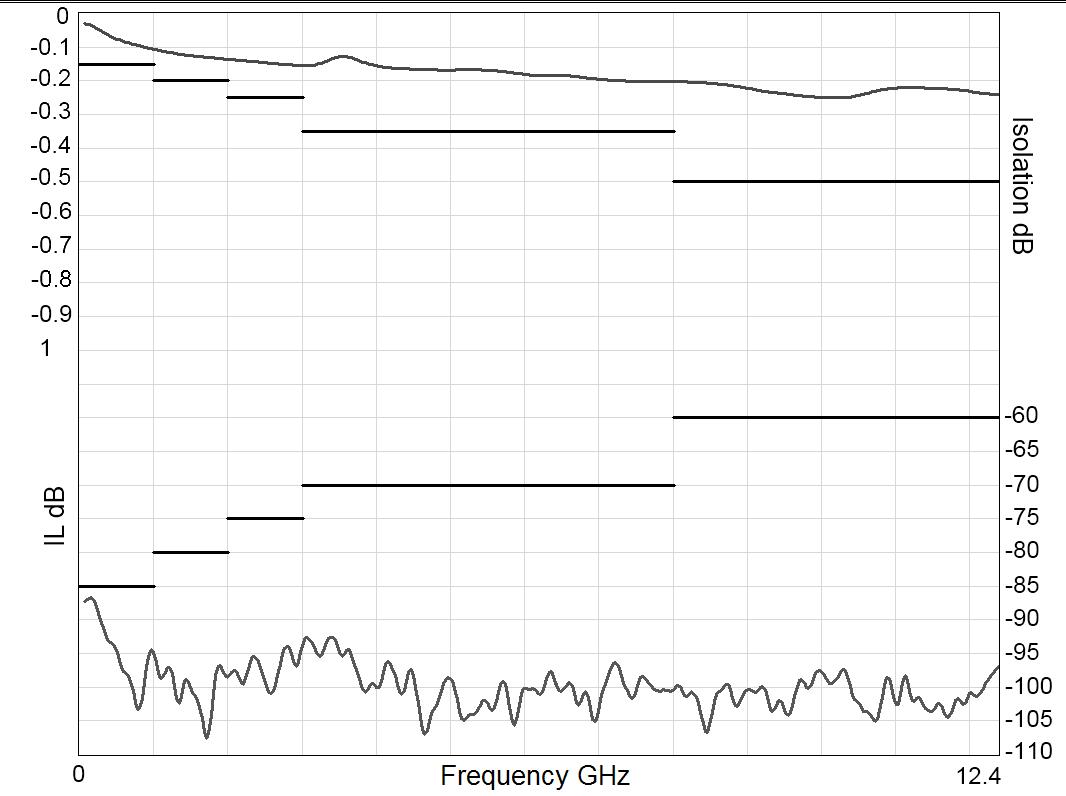
Frequency (GHz)
Example: SPDT SMA up to 18 GHz
INSERTION LOSS & ISOLATION

Frequency (GHz)
Notes
See electrical schematics from page 2-20 to 2-23.
V.S.W.R

Frequency (GHz)
V.S.W.R

Frequency (GHz)
RAMSES Series
TYPICAL OUTLINE DRAWING
EXAMPLE: SPDT N UP TO 12.4 GHz WITH PINS
EXAMPLE: SPDT SMA UP TO 18 GHz
Notes
All dimensions are in millimeters [inches].
EXAMPLE: SPDT N UP TO 12.4 GHz WITH D-SUB
RAMSES Series
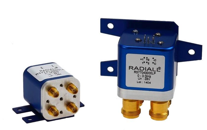
DPDT LOW PIM UP TO 18 GHz
PART NUMBER SELECTION
SERIES PREFIX
FREQUENCY RANGE
1: N up to 12� 4 GHz
4: SMA up to 18 GHz
TYPE
1: Failsafe
2: Failsafe + I C
3: Latching
4: Latching + I.C.
5: Latching + S.C.O. [1]
6: Latching + S.C.O. + I.C. [1]
ACTUATOR VOLTAGE
2: 12 Vdc
3: 28 Vdc
TTL OPTION
0: Without TTL driver
1: With TTL driver [1 & 3]
OPTIONS
0: Without option
1: Positive common [2]
3: With suppression diodes
To meet growing market demands created by the deployment of 4G/LTE networks, Radiall has introduced a new range of Low PIM switches. RAMSES DPDT Low PIM switches are perfectly suited for RF test systems and test benches requiring excellent passive intermodulation performance up to 18 GHz; with a guarantee PIM performance of -160 dBc at +43 dBm over a life span of 2 million switching cycles. These products are specific to instrumentation and telecommunication applications
Example of P/N: R577163105LP is a DPDT Low PIM N 12.4 GHz latching with Indicators, Self Cut-Off, 28 Vdc, TTL driver, D-Sub connector.
4: With suppression diodes and positive common [2]
ACTUATOR TERMINALS
0: Solder pins
5: D-Sub connector [4]
Notes
I.C.: Indicator contact - S.C.O.: Self Cut-Off
1. Suppression diodes are already included in Self Cut-Off & TTL option
2. Positive common shall be specified only with type 3, 4, 5 & 6 because failsafe models can be used with both polarities
3. Polarity is not relevant to application for switches with TTL driver
RAMSES Series
GENERAL SPECIFICATIONS
Average power See Power Rating Chart on page 1-13
rating
Switching time (max) ms 15 Life (min) 2 million cycles
Connectors SMA - N
Actuator terminals
Solder pins or male 9 pin D-Sub connector
Operating temperature range -40°C to +85°C
Storage temperature range -55°C to +85°C
Vibration (MIL STD 202, method 204D, cond C)
(MIL STD 202, method 213B, cond G)
RF PERFORMANCE
CONNECTORS
PASSIVE INTERMODULATION
TONE 1 1,810 MHz, approximately 43 dBm
TONE 2 1,850 MHz, approximately 43 dBm
3RD ORDER PIM 160 dBc at 1,770 MHz
Depending on application, carrier powers and frequencies — PIM measurements can vary. PIM testing is not measured during product acceptance test.
OUTSTANDING PIM PERFORMANCE
RAMSES Series
TYPICAL RF PERFORMANCE
Example: DPDT N up to 12.4 GHz
INSERTION LOSS & ISOLATION
Frequency (GHz)
Example: DPDT SMA up to 18 GHz
INSERTION LOSS & ISOLATION
Frequency (GHz)
Notes
See electrical schematics from page 4-10 to 4-13.
V.S.W.R
Frequency (GHz)
V.S.W.R

Frequency (GHz)
RAMSES Series
TYPICAL OUTLINE DRAWING
EXAMPLE: DPDT N UP TO 12.4 GHz WITH PINS
EXAMPLE: DPDT SMA UP TO 18GHz WITH PINS
Notes
All dimensions are in millimeters [inches].
EXAMPLE: DPDT N UP TO 12.4 GHz WITH D-SUB
EXAMPLE: DPDT SMA UP TO 18 GHz WITH D-SUB
RAMSES Series
SPNT LOW PIM UP TO 18 GHz

To meet growing market demands created by the deployment of 4G/LTE networks, Radiall has introduced a new range of Low PIM switches. RAMSES SPnT Low PIM switches are perfectly suited for RF test systems and test benches requiring excellent passive intermodulation performance up to 18 GHz; with a guarantee PIM performance of -160 dBc at +43 dBm over a life span of 2 million switching cycles. These products are specific to instrumentation and telecommunication applications
Example of P/N: R573403600LP is a SP6T Low PIM SMA up to 18 GHz, Normally Open, 28 Vdc, without option and solder pins.
PART NUMBER SELECTION
SERIES PREFIX
MODEL
3: Without 50 Ω termination
RF CONNECTORS
1: N up to 12� 4 GHz
4: SMA up to 18 GHz
TYPE
0: Normally open
1: Normally open + I �C �
2: Latching
3: Latching +I.C.
4: Latching + S.C.O. [1]
5: Latching + S.C.O. + I.C. [1]
8: Latching + S.C.O. + A.R. [1]
9: Latching + S.C.O. + I.C. + A.R. [1]
ACTUATOR VOLTAGE
2: 12 Vdc
3: 28 Vdc
R57
LP
ACTUATOR TERMINALS
0: Solder pins
5: D-Sub connector
OPTIONS
0: Without option
1: Positive common [5]
2: Compatible TTL driver [1 & 2]
3: With suppression diodes
4: With suppression diodes and positive common [3]
8: BCD TTL driver compatible [1, 2, 4, & 5]
NUMBER OF POSITIONS
4: 4 Positions
6: 6 Positions
Notes
I.C.: Contact / S.C.O.: Self Cut-Off / A.R.: Auto Reset
1. These models are already equipped with suppression diodes
2. Polarity is not relevant to application for switches with TTL driver
3. Option available only for type 0, 1, 2 and 3
4. Latching BCD driver enables also a global reset through driver code 0000 (see BCD logic coding page 1-11)
5. Option available only with type 0, 1, 2, 3 and with type 8 and 9 combined with 28 Vdc.
RAMSES Series
GENERAL SPECIFICATIONS
Type 2, 3, 4 and 5:
Latching models have a RESET pin which commands the reset of all positions. This command should be used before switching from one position to another. If not, two positions will be set at the same time.
Note: During the RESET operation the global current is the nominal operating current multiplied by the number of positions.
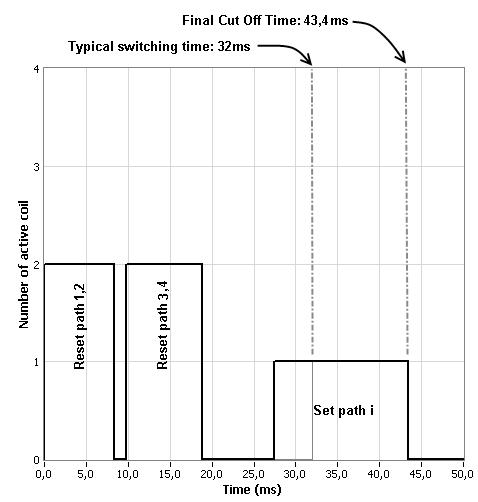
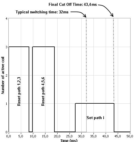
Type 8, 9:
Latching models with AUTOMATIC RESET are available; these products have an internal SET/RESET circuit which automatically resets all the non-selected positions and sets the desired position. This option simplifies the use of latching switches by suppressing the RESET command in switching sequence. An electronic circuit supplies successively groups of 2, 3 or 4 actuators, in order to limit the maximum current. The current with this option is the total current of 2, 3 or 4 reset coils in the same time (see table below).
Example: During the AUTOMATIC RESET operation, at 28 Vdc, 4 position switch has a temporary consumption of only 250 mA, during 40 ms maximum.
SWITCHING SEQUENCE
Notes
See electrical schematics from page 5-38 to 5-43.
GENERAL SPECIFICATIONS
OPERATING MODE NORMALLY OPEN
Average power See Power Rating Chart on page 1-13
Switching time (max) ms 15 For automatic reset models: 40 Life (min) 2
Connectors SMA - N
Actuator terminals
Solder pins or male 25 pin D-Sub connector
Operating temperature range -25 °C to +70 °C
Storage temperature range -55 °C
(MIL STD 202, method 213B, cond C)
*Reset: supply voltage time 1 sec. max./duty cycle 10%
RF PERFORMANCE
CONNECTORS
PASSIVE INTERMODULATION
TONE 1 1,810 MHz, approximately 43 dBm
TONE 2 1,850 MHz, approximately 43 dBm
3RD ORDER PIM 160 dBc at 1,770 MHz
Depending on application, carrier powers and frequencies — PIM measurements can vary. PIM testing is not measured during product acceptance test.
OUTSTANDING PIM PERFORMANCE
RAMSES Series
TYPICAL RF PERFORMANCE
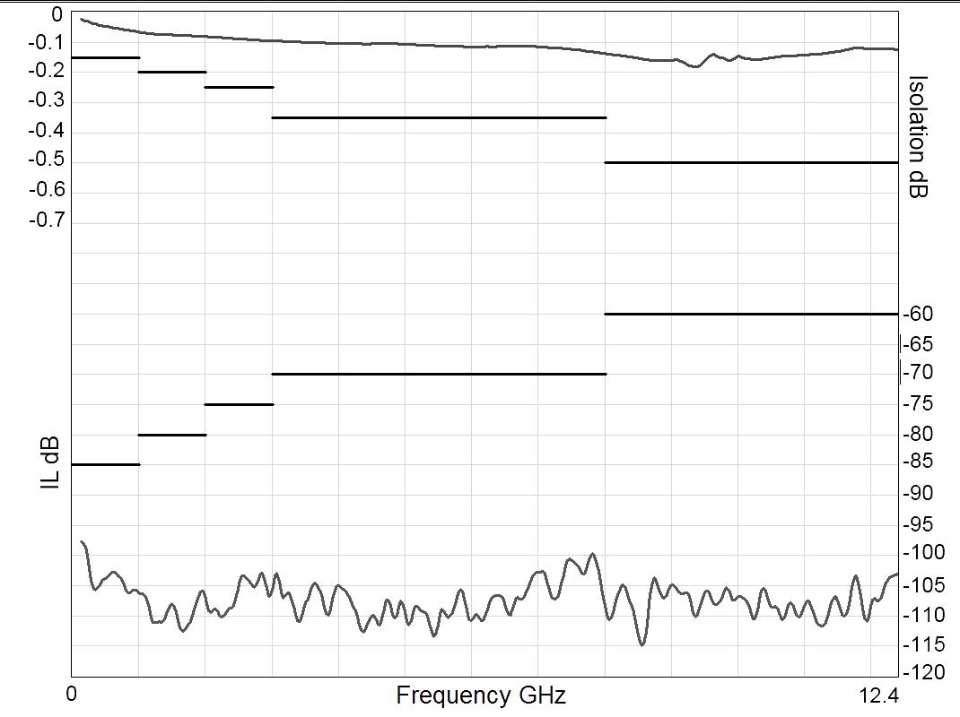
Example: SP6T N up to 12.4 GHz
INSERTION LOSS & ISOLATION

Frequency (GHz)
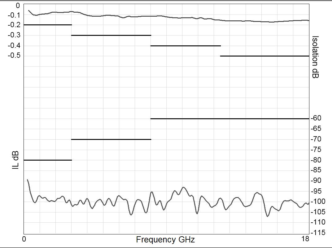
Example: SP6T SMA up to 18 GHz
INSERTION LOSS & ISOLATION

Frequency (GHz)
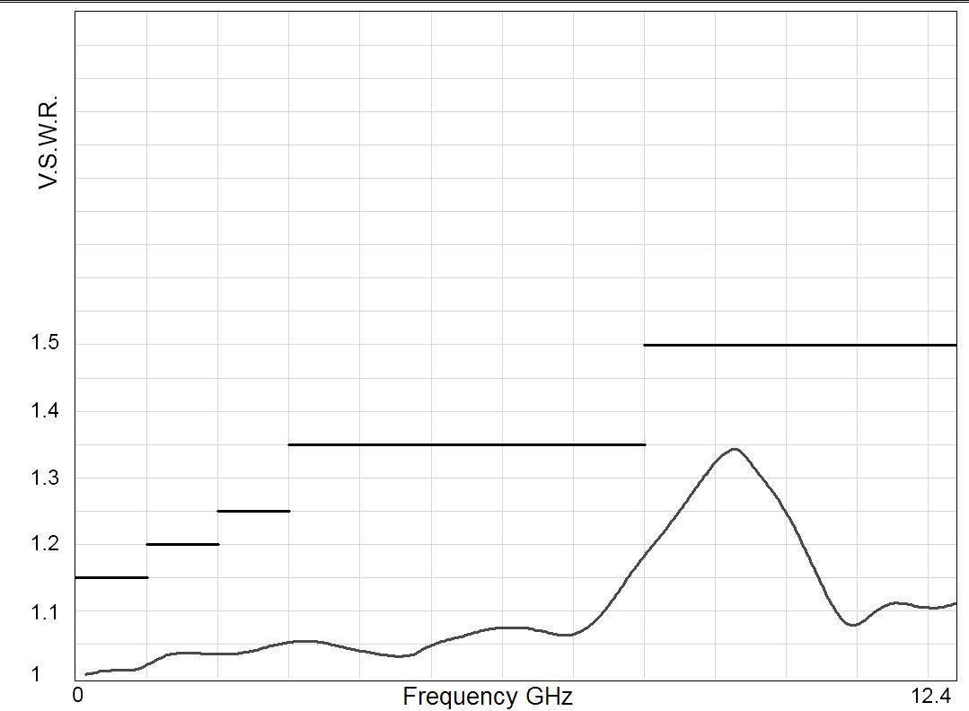
V.S.W.R
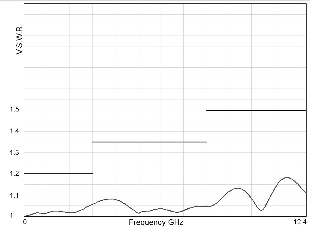
Frequency (GHz)
V.S.W.R

Frequency (GHz)
TYPICAL OUTLINE DRAWING
Example: SPnT SMA up to 18 GHz
SOLDER PINS
Type 0 or 1 with option 0 - 1 - 3 or 4
Type 2 or 3 with option 0 or 1
SOLDER PINS
Type 0 or 1 with option 2 or 8
Type 2 or 3 with option 2 - 3 - 4 or 8
Type 4 - 5 - 8 or 9 with option 0 - 2 or 8
D-SUB CONNECTOR All models
Notes
All dimensions are in millimeters [inches].
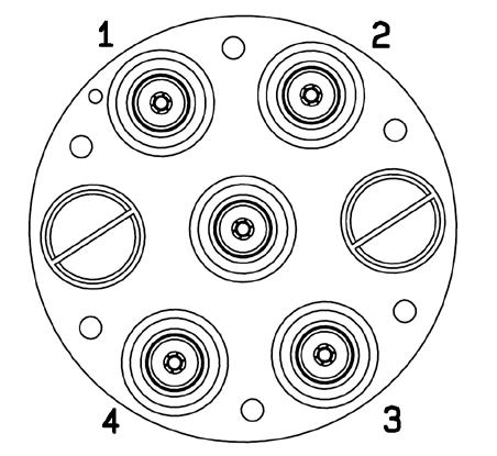
Example: SPnT N up to 12.4 GHz
RF CONNECTOR ALLOCATION

Notes
All dimensions are in millimeters [inches].


COAXIAL LOW PIM SWITCHES - ELECTRICAL SCHEMATICS
TYPE FAILSAFE LATCHING
Without option Without option Cut-off C+ and suppression diodes
Indicator contact Indicator contact Cut-off and I.C. C+, suppression diodes and I C
Suppression diodes Suppression diodes Cut-off and TTL Driver C+ and cut-off
Page Number
Options
Suppression diodes and I C Suppression diodes and I C Cut-off, TTL and I.C. C+, cut-off and I.C.
SPDT see page 2-20 see page 2-21 see page 2-22 see page 2-23
DPDT see page 4-10 see page 4-11 see page 4-12 see page 4-13
TYPE NORMALLY OPEN LATCHING
Without option BCD TTL driver Without option Cut-off
Indicator contact BCD TTL driver and I C Indicator contact Cut-off and I.C.
Options
Driver, Cutoff and Auto reset C+ and suppression diodes
Driver, Cutoff, Auto reset and I C C+, suppression diodes and I C
Suppression diodes C+ Suppression diodes Cut-off and Auto reset BCD TTL Driver, Cut-off and Auto reset C+, Cut-off and Auto reset
Suppression diodes and I �C � C+ and I �C � Supression diodes and I �C � Cut-off, Auto reset and I �C � BCD TTL Driver, Cut-off, Auto reset and I �C � C+, Cut-off, Auto reset and I �C �
Driver C+ and suppression diodes