SIMPLIFICATION IS OUR INNOVATION Visit www.radiall.com for more information SECTION 18 MISCELLANEOUS: BR2/TYPE 43/UHF/IMP/ IMP-MAX/UMP R605/R214/R155/R107
BR2/TYPE 43/UHF/IMP/IMP-MAX/UMP | 18-1 SIMPLIFICATION IS OUR INNOVATION Visit www.radiall.com for more information TYPE 43 Introduction 18-2 Interface ��������������������������������������������������������������������������� 18-2 Characteristics 18-3 Panel Drilling ������������������������������������������������������������������ 18-6 STANDARD DENSITY Plugs 18-4 Sockets ���������������������������������������������������������������������������� 18-4 Receptacles 18-4 HIGH DENSITY Plugs 18-5 U Links ���������������������������������������������������������������������������� 18-6 ULTRA HIGH DENSITY Plugs 18-5 IMP Introduction ������������������������������������������������������� 18-7 to 18-8 Full Solderless 18-9 to 18-10 Full Solderless Solutions ������������������������������� 18-11 to 18-13 Characteristics ����������������������������������������������� 18-14 to 18-15 Board to Board Connectors 18-16 Assembly Instructions�������������������������������������������������� 18-16 Receptacle Packaging 18-17 IMP-MAX Introduction 18-18 Characteristics �������������������������������������������������������������� 18-19 Section 18 Table of Contents UMP Characteristics 18-15 Receptacles ��������������������������������������������������������������������18-20 Pigtails 18-20 Cable Assemblies ����������������������������������������������������������18-20 Tools & Accessories ������������������������������������������������������ 18-21 Assembly Instructions 18-22 BR2 Interface 18-23 Characteristics ������������������������������������������������������������� 18-23 Plugs 18-24 Jacks ��������������������������������������������������������������������������������18-24 Receptacles 18-25 Caps ������������������������������������������������������������������������������� 18-25 Gasket 18-26 Panel Drilling ����������������������������������������������������������������� 18-26 UHF Interface 18-27 Characteristics ��������������������������������������������������������������18-27 Plugs 18-28 Receptacles ������������������������������������������������������������������� 18-28 Adapter 18-28
Type 43
INTERFACE
INTRODUCTION
GENERAL
• Standard coaxial connectors
• Reliable lock coupling
• 3 types: Standard Density (12 7mm)
• High Density (10mm)
• Ultra High Density (9mm)
APPLICABLE STANDARDS
• BS9210 F0022
APPLICATIONS
• Telecom DDF (Digital Distribution Frames)
JACK PLUG
C DIA 3 � 4 3 � 475 �134 �137
D DIA 0 48 0 52 019 02
E DIA 0 125 0 225 005 009
G
P 0 15 0 25 006 01
R 0 05 0 15 002 006
S - 0 13 - 005
T 0 1 0 2 004 008
18-2 | BR2/TYPE 43/UHF/IMP/IMP-MAX/UMP SIMPLIFICATION IS OUR INNOVATION Visit www.radiall.com for more information
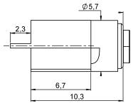
75Ω DC - 3 GHz LETTER MM INCH MIN MAX MIN MAX
244 245
207
A DIA 6 20 6 23
B DIA 5 25 NOM
NOM
F DIA 5 97 6 02 235 237
M
N
3 5 3 55 138 14 H 2 4 2 55 095 1 I 0 05 0 175 002 007 J 0 00 0 10 0 00 004 K 0 25 0 35 01 014 L 1 35 - 053 -
- 2 05 - .081
- 0�18 - �007 O 0 58 NOM 023 NOM
LETTER MM INCH MIN MAX MIN MAX A DIA
31 6 26 248 25 B
25
207 NOM C DIA
22 3 � 30
D 3 2 3 53 126 139 E 3 63 3 83 143 151 F - 1 8 - 071 G 3 61 3 77 142 148 H 0 23 0 38 009 015 I 0 23 0 48 009 019 J 1 475 1 97 058 078
6
DIA 5
NOM
3 �
�127 �13
Type 43
TYPE 43 GENERAL TECHNICAL SPECIFICATION
Radiall 75Ω coaxial Type 43 connectors are designed to meet or exceed the requirements of BS9210 F0022. The following information is subject to change without notice� The performance values shown are typical and may not relate to all connector styles available�
CHARACTERISTICS
TEST / CHARACTERISTICS
ELECTRICAL CHARACTERISTICS
VALUES / REMARKS
Impedance 75Ω
Frequency Range DC - 3 GHz
Temperature Range -40 °C to + 100 °C
V.S.W.R. (Straight Connectors) 1� 20 max
V.S.W.R. (Right Angle Connectors) 1 25 max
Voltage Rating
Dielectric Withstanding Voltage
Insulation Resistance
MECHANICAL CHARACTERISTICS
Vrms max
Vrms min
MΩ min
Durability 250 matings
Cable Retention (Plug Connectors) (Socket Connectors) 60 to 220 N min [3]
Center Contact Retention (Plug Connectors) (Socket Connectors) 22 N min
Weight 10 g (grams) typical
MATERIALS AND PLATING
Components
Body Components [1]
Outer Contact
Center Contact (Male)
Center Contact (Female)
Panel Grommet
Ferrule
Panel Mounting Hardware [2] Brass or Phosphor Bronze Nickel
Notes
1.In general all Type 43 series connector bodies are gold plated in mating areas.
As a note, the single piece Type 43 connector body is gold plated in the mating area with other surfaces being nickel coated. All multi-piece connector bodies comprise of a gold plated front body (mating area) and a nickel plated back body (crimp area).
2. Panel mounting hardware includes components such as - nut, washer, spacer etc.
3. Lower cable retention value for RG179 - 60 N min and BT3002/TZC 75024 - 150 N min
BR2/TYPE 43/UHF/IMP/IMP-MAX/UMP | 18-3 SIMPLIFICATION IS OUR INNOVATION Visit www.radiall.com for more information
500
1500
5000
Materials Platings
Brass Selective Gold
Bronze Selective Gold
Brass Gold
Gold
PTFE
Beryllium Copper
Insulator
N/A
Polyacetal
N/A
Brass Nickel
PLUGS, SOCKETS & RECEPTACLES
STRAIGHT SOCKETS CRIMP TYPE FOR FLEXIBLE CABLES
STRAIGHT BULKHEAD RECEPTACLE WITH SOLDER POT
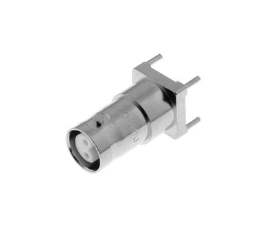
STRAIGHT PCB PLUG RECEPTACLES
18-4 | BR2/TYPE 43/UHF/IMP/IMP-MAX/UMP SIMPLIFICATION IS OUR INNOVATION Visit www.radiall.com for more information Standard Density
CABLE GROUP CABLE GROUP DIA. BT REFERENCE PART NUMBER DIMENSIONS PACKAGING A B C D BT3002 3 6/75/D S 43/5 FS R214 083 922 0 36 4 47 3 2 20 Pieces PART NUMBER PANEL DRILLING PACKAGING R214 553 000 P02 Unit BT REFERENCE PART NUMBER PANEL DRILLING PACKAGING P 43/1 D R214 426 704 P01 100 Pieces
High Density/Ultra High Density
PLUGS
STRAIGHT PLUGS CRIMP TYPE FOR FLEXIBLE CABLES
STRAIGHT SOCKETS CRIMP TYPE FOR FLEXIBLE CABLES
STRAIGHT PLUG CRIMP TYPE FOR FLEXIBLE CABLES
BR2/TYPE 43/UHF/IMP/IMP-MAX/UMP | 18-5 SIMPLIFICATION IS OUR INNOVATION Visit www.radiall.com for more information
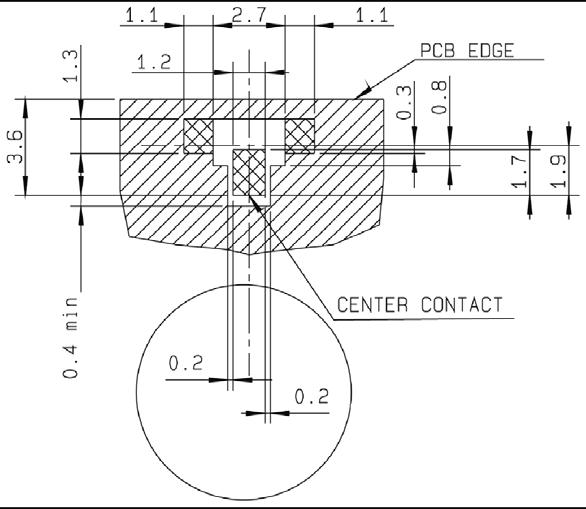
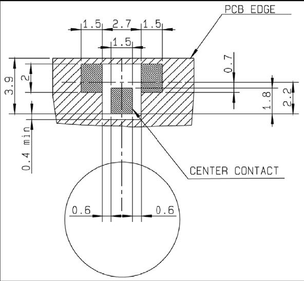
CABLE GROUP CABLE GROUP DIA. BT REFERENCE PART NUMBER DIMENSIONS PANEL DRILLING PACKAGING A B C D RG179 2 6/75/S HDC 43/4 GTIS R214 318 702 0 38 1 73 3 25 3 5 P03 20 Pieces BT3002 3 6/75/D HDC 43/5 GTIS R214 318 722 0 36 2 10 4 47 RA7000 4 5/75/D HDC 43/7 GTIS R214 325 742 0 69 3 00 5 48 CABLE GROUP CABLE GROUP DIA. BT REFERENCE PART NUMBER DIMENSIONS PACKAGING A B C D RG179 2 6/75/S HDC 43/4FS R214 088 902 0 38 1 73 3 25 32 20 Pieces BT3002 3 6/75/D HDC 43/5FS R214 088 922 0 35 2 10 4 47 30 CABLE GROUP CABLE GROUP DIA. BT REFERENCE PART NUMBER FIG PANEL DRILLING PACKAGING RG179 2 6/75/S UHDC 43/4 GTIS R214 320 702 1 P04 20 Pieces BT3002 3 6/75/D UHDC 43/5 GTIS R214 320 722 2 FIG. 1 FIG. 2
U LINKS
PANEL DRILLING
18-6 | BR2/TYPE 43/UHF/IMP/IMP-MAX/UMP SIMPLIFICATION IS OUR INNOVATION Visit www.radiall.com for more information High Density
BT REFERENCE PART NUMBER FIG. PACKAGING U Link 10A R214 797 703 1 50 Pieces U Link 10B R214 798 703 2 U Link 13A R214 790 703 3 U Link 13B R214 791 703 4 U Link 9A R214 797 723 5 U Link 9B R214 798 723 6
FIG. 1
FIG. 4
FIG. 5
FIG. 6
FIG. 2
mm Maxi mini A 7.35 7.05 A P01 P02 P04 P03 mm Ma xi mi ni A 1. 5 1. 2 B 2. 0 1. 7 C 5. 1 5. 06 A DI A B DI A 4 ho le s C mm Maxi mini A 8.04 7.94 B 7.5 7.4 A B mm Maxi mini A 7.55 7.5 A
FIG. 3
IMP/UMP
INTRODUCTION
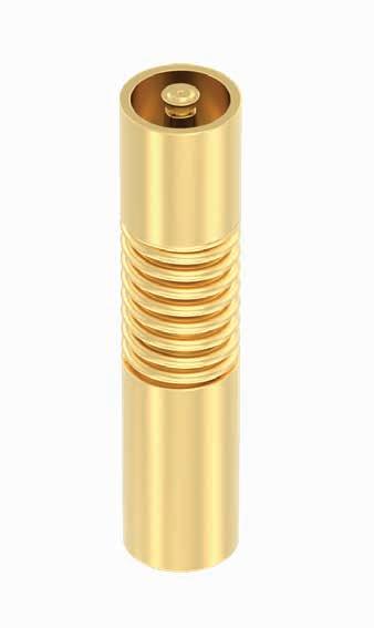
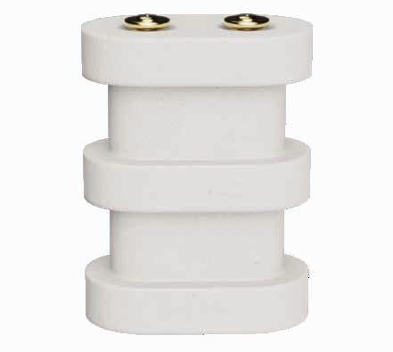
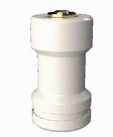
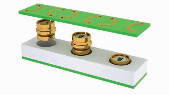
Radiall introduced the MMP contact technology (Micro Miniature Pressure) in 2001 to meet the needs of the telecommunication industry for ultra low profile and cost effective board connectors. The MMP technology can be found in 2 product lines:
• IMP series: RF Board-to-Board application
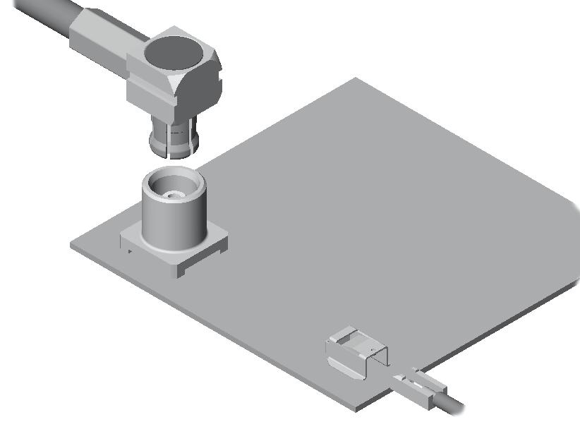
• UMP series: RF board to wire application
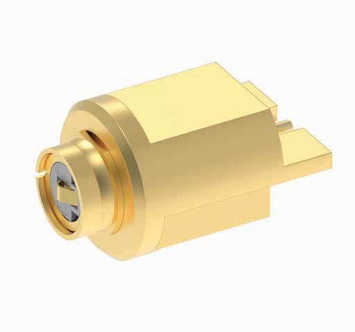
The IMP series (Interconnect Micro miniature Pressure contact) consists of 1 coaxial connector when usually the same application requires either 2 coaxial connectors (a male SMT receptacle and a female SMT receptacle), or 3 coaxial connectors (2 SMT receptacles and an adapter)�
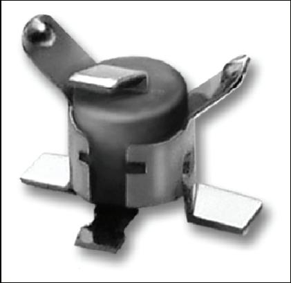
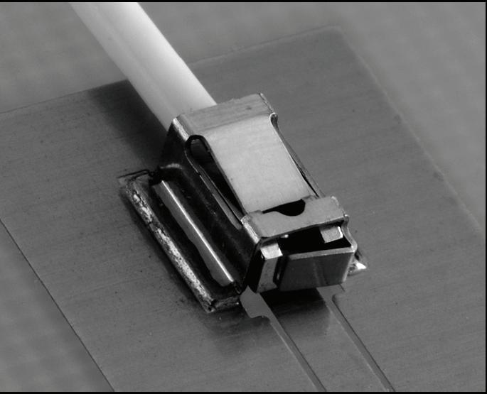
The UMP series ( Ultra Miniature Pressure contact) consists of 1 coaxial plug and 1 SMT edge receptacle�
BR2/TYPE 43/UHF/IMP/IMP-MAX/UMP | 18-7 SIMPLIFICATION IS OUR INNOVATION Visit www.radiall.com for more information
IMP One Piece Connector MCX 2 Coaxial Connectors MMS 3 Coaxial Connectors BOARD-TO-BOARD APPLICATION BOARD-TO-BOARD APPLICATION
IMP UMP
MCX SERIES
UMP SERIES
IMP/UMP
IMP INSTALLATION
IMP PRODUCT FEATURES
• Cost effective solution: one piece connector only
• High density
• Lightweight connector: (example 0�02 g for the IMP 2 mm)
• Low profile for a board-to-board coaxial connections (2 mm)
The distance between the 2 boards should be precisely measured by a mechanical device (such as spacers)
Contact Radiall for support regarding the layout in your particular application� Application notes are available upon request.
IMP PRODUCT RANGE
IMP is available in 2 mm board-to-board distance. Other heights can be developed upon request.
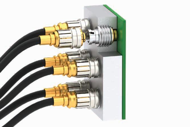
UMP PRODUCT FEATURES
• Low profile: 2 mm and 3 mm
• Small space for connection: needs only 2 mm of height
• Cost effective solution: 1 coax connector only
• Large cable range from 0 8 to 2 6 mm
• High durability, up to 10,000 cycles
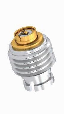
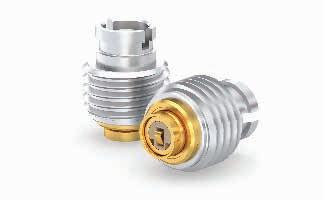
UMP TYPE OF MATING:
• Lock: - Can only be disconnected using a tool
- Number of matings 100
- Withstands severe vibrations
• Snap-on: - Number of matings 3000
• Snap-on: - Number of matings 10,000
- For test applications
Plug exist with the 3 types of mating:
APPLICATIONS
IMP and UMP series can be used for board-to-board and board-to-antenna applications:
• WLAN
• Automotive
• RFID
• GPS Receivers
• Handheld Radios
18-8 | BR2/TYPE 43/UHF/IMP/IMP-MAX/UMP SIMPLIFICATION IS OUR INNOVATION Visit www.radiall.com for more information
LOCK
SNAP-ON
SLIDE-ON
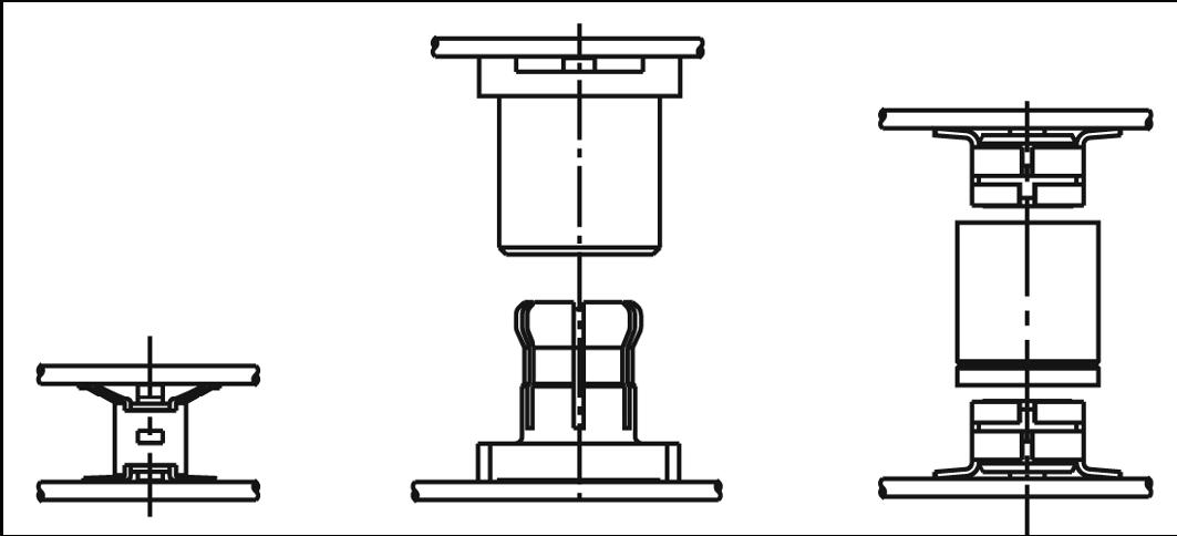
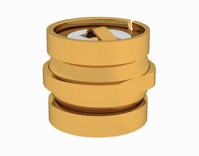
IMP
FULL SOLDERLESS
IMP FULL SOLDERLESS FEATURES
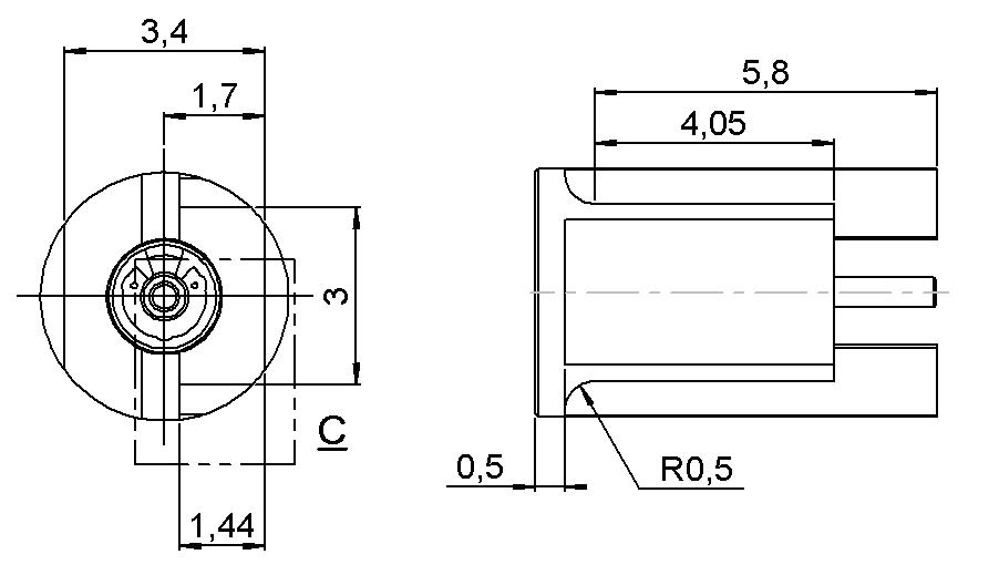
• Low profile (Board-to-Board distance: 1.41 mm) and small pitch (IMP diameter: 2.8 mm)
• High frequency range (designed for Ku band applications – up to 20 GHz)
• Designed to work in harsh environments, such as airborne platforms
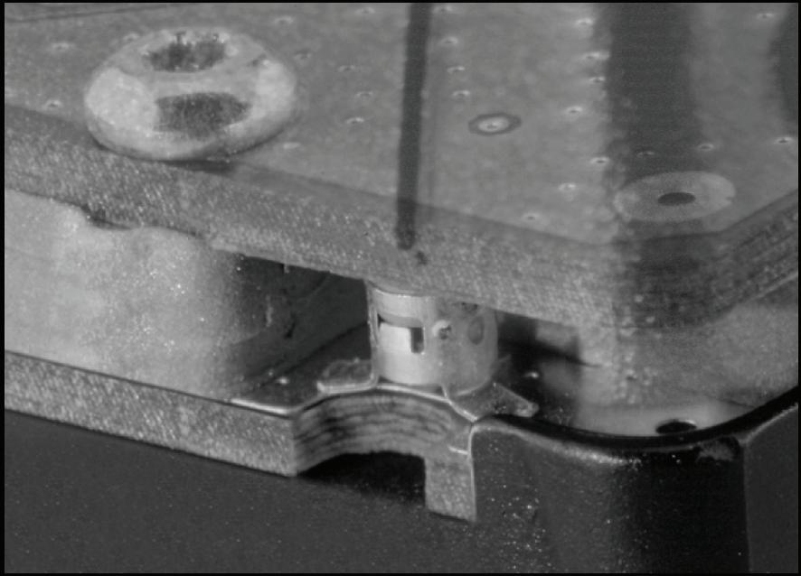
IMP FULL SOLDERLESS INSTALLATION
Most targeted applications for such low Board-to-Board distances or high density integration use a cold plate between Printed Circuit Boards (PCB)�
Using this application constraint to receive IMP (to create a cavity) generates a high cost advantage for product integration or maintenance� Its design delivers high performances and signal integrity even in vibration conditions
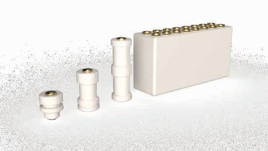
IMP FULL SOLDERLESS RANGE
IMP Full Solderless Range:
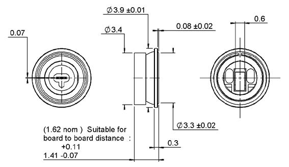
• IMP-LP (Low Profile)
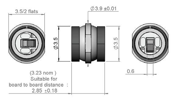
The “single model” IMP-LP provides a lower Board-to-Board distance up to 1.41 mm, with an outer diameter of 3.9 mm. To achieve higher Board-to-Board distance (up to 5 mm), Radiall designed a “double model” that provides twice the axial tolerance of the “single model” with the same outer diameter (3 9 mm)
• IMP-HD (High Density)
When applications require a high density integration, Radiall offers a smaller product with a diameter of 2.8 mm. As most of those applications require a higher Board-to-Board distance, IMP-HD features a wide axial tolerance up to 1 mm. Low phase noise performance is available upon request.
• IMP-LP “Hybrid”
This solderless solution addresses interconnections between two PCBs or a front panel to a PCB� Encapsulating the IMP-LP “double model” into a panel front interface (eg: SMP, SMP-Lock. etc.), this product becomes an IMP-LP Hybrid that combines an interface similar to IMP-LP’s size and performance� Please contact Radiall for more information on this product family
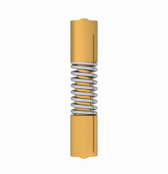
• IMP-SR
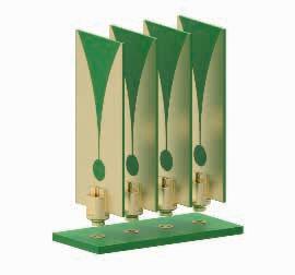
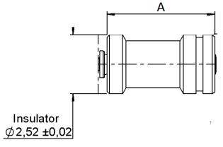
The IMP-SR is a ground-breaking solderless product adapted to meet RF, data and signal interconnection needs for emerging active antennas� With a minimum board to board distance of 3.1 mm and a diameter of 2.52 mm, its simple architecture makes it possible to easily adapt it to meet customer requirements. It provides high electrical performance up to 70 GHz and very low insertion losses of -0�45 dB @ 20 GHz� It can reach over 100Gb PAM4� The IMP-SR is made of a central contact and an insulator. For RF applications, the ground contact is recreated directly by the cold plate, already present in the radar architecture, and in which the connector will be integrated.
BR2/TYPE 43/UHF/IMP/IMP-MAX/UMP | 18-9 SIMPLIFICATION IS OUR INNOVATION Visit www.radiall.com for more information
IMP
APPLICATIONS
As designed for applications up to 70 GHz, IMP Full solderless range is dedicated for antennas, radars and seekers.
ELECTRICAL CHARACTERISTICS
MECHANICAL & ENVIRONMENTAL CHARACTERISTICS
18-10 | BR2/TYPE 43/UHF/IMP/IMP-MAX/UMP SIMPLIFICATION IS OUR INNOVATION Visit www.radiall.com for more information
IMP-LP IMP-HD IMP-SR RF IMP-SR DATA Impedance 50Ω 100Ω Frequency Range 18 GHz 20 GHz 70 GHz 27 GHz V.S.W.R. ≤ 1.3 @ 12 GHz ≤1.5 @ 18 GHz ≤ 1.4 @ 18 GHz 1 3 typInsertion Loss 0 20 dB max 0 15 dB max -0 45 dB Maxi @ 20 GHz -
IMP-LP IMP-HD IMP-SR Weight ≥ 110 mg 320 mg 20 mg Outer Diameter 3 9 mm 2 8 mm 2 52 mm Board to Board Distance ≥ 1.41 mm Typ 13 4 mm ≥ 3.10 Operating Temperature -55 / +125 °C -55 / +165 °C
- Solderless One Side Only
For information on other Board-to-Board distances, please contact Radiall.
R107 064 930
R107 064 944
R107 064 954
Phase Noise Performances
Phase Noise Performances
BR2/TYPE 43/UHF/IMP/IMP-MAX/UMP | 18-11 SIMPLIFICATION IS OUR INNOVATION Visit www.radiall.com for more information IMP FULL
IMP-LP IMP-HD IMP-LP
SOLDERLESS SOLUTIONS
HYBRID
FIG. 1
FIG. 1
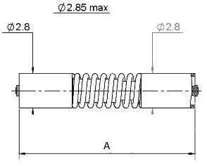
FIG. 2
PART NUMBER FIG. BOARD TO BOARD DISTANCE (A) NOTE R107 802 000 1 1� 41 mmR107 803 000 2 2 85 mmR107 803 020 2 3 10 mmR107 807 000 2 5 �78 mmR107 808 000 2 6 15 mmR107 804 000 3 2 80 mm SMT
FIG. 3
PART NUMBER FIG. BOARD TO BOARD DISTANCE (A) NOTE
1 13 4 mm -
1 13 4 mm Low
1 16 5 mm
PART NUMBER FRONT INTERFACE
Low
R107 820 300 SMP-LOCK R107 820 310 SMP Smooth Bore R107 820 320 SMP Limited Detent R107 851 000 MCC#12
IMP-LP EDGE PAD RECEPTACLE
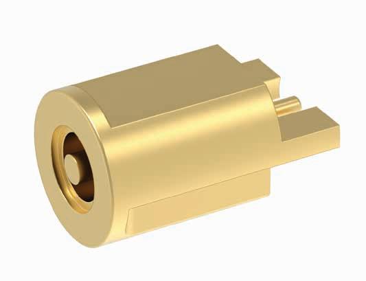
R107 830 000 1
IMP-LP HYBRID EDGE RECEPTACLE
R107 821 010
IMP-SR “RF”
Pad Receptacle Compatible with R107 820 300 / R107 820 310 / R107 851 000
Receptacle
825 060
Other board to board distance, please contact Radiall
18-12 | BR2/TYPE 43/UHF/IMP/IMP-MAX/UMP SIMPLIFICATION IS OUR INNOVATION Visit www.radiall.com for more information
FIG. 1
FIG. NOTE
FIG. 1 FIG. 1
PART NUMBER
PART NUMBER FIG. NOTE
PART NUMBER FIG. A R107
1 3 10 mm R107
1 4 84
R107
1 6
1 8
1 10
1 16
1 IMP-LP in Edge
825 020
825 000
mm
50 mm R107 825 010
mm R107 825 050
mm R107 825 040
mm
IMP
IMP-SR “SIGNAL”
Other board to board distance, please contact Radiall
IMP-SR “DATA”
PART NUMBER
R107 803 050
R107 803 060
Other configuration, please contact us
BR2/TYPE 43/UHF/IMP/IMP-MAX/UMP | 18-13 SIMPLIFICATION IS OUR INNOVATION Visit www.radiall.com for more information
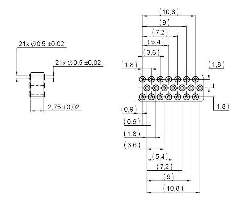
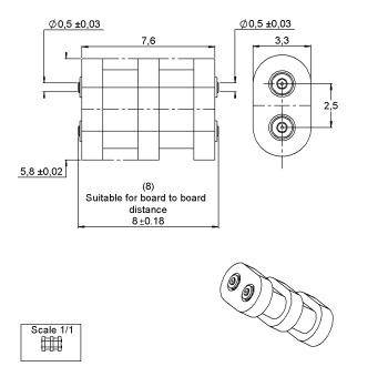
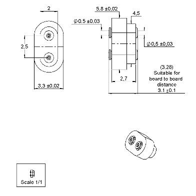
FIG. 1
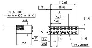
PART NUMBER FIG. NUMBER OF CONTACTS NOTE R107 838 000 1 16 8 00 mm R107 833 000 2 21 3 10 mm
FIG. 2
IMP
IMP
CHARACTERISTICS
TEST / CHARACTERISTICS
ELECTRICAL CHARACTERISTICS
V.S.W.R.
RF Leakage
Dielectric with Standing Voltage
MECHANICAL CHARACTERISTICS
Cable Contact Retention
Axial force – Mating End
Axial force – Opposite End
VALUES / REMARKS
ENVIRONMENTAL CHARACTERISTICS
Hermetic Seal NA Atm cm3/s
Panel Leakage NA
MATERIALS
Center Contact
PLATING
Center Contact Gold
18-14 | BR2/TYPE 43/UHF/IMP/IMP-MAX/UMP SIMPLIFICATION IS OUR INNOVATION Visit www.radiall.com for more information
IMP LP IMP HD
50Ω Frequency 0-18 GHz 0-20 GHz
Impedance
+ 0 0000 x F
Maxi
0 2 dB Max 0 2 F(GHz) dB Max
(GHz)
Insertion Loss
-Voltage
225
Max
Rating
Veff
500
Max Insulation
1,000
min
Veff
Resistance
MΩ
IMP LP IMP HD
0 5 N mini 0 5 N mini 10 N mini 10 N mini
50 Cycles mini Nominal Weight 0 1600 g 0 3800 g Minimum
Typ 5N Overall length: L = 13 9 Maxi Load = 4 5 N min Maximum
Typ 5N Overall length: L = 12 9 mini Load = About 10 N Max
•
•
Mating Life
Compression
Compression
IMP LP IMP HD Operating Temperature -55/+125 °C -65/+165 °C
IMP LP IMP HD
Bronze Beryllium Copper
Beryllium
Beryllium
Steel
Body
Copper Insulator Peek Other Parts
Copper
IMP LP IMP HD Body NPGR NPGR
Gold
IMP/UMP
TEST / CHARACTERISTICS
ELECTRICAL CHARACTERISTICS
VALUES / REMARKS
MECHANICAL CHARACTERISTICS
Radial Misalignment in mm (inch)
ENVIRONMENTAL CHARACTERISTICS
MATERIALS
PLATING
Body/Outer Contact
Beryllium Copper -Plug: Brass -Receptacle: Berylium copper
Center Contact Brass (plug only)
Insulator Polyethercetone PTFE
Body Gold Center Contact
BR2/TYPE 43/UHF/IMP/IMP-MAX/UMP | 18-15 SIMPLIFICATION IS OUR INNOVATION Visit www.radiall.com for more information
IMP UMP Impedance 50Ω Frequency DC - 6 GHz V.S.W.R. Max 1 3 1 05 + 0 03F (mated connectors)
Loss (dB) 0.2 √F (GHz) RF Leakage -40dB min at 2 GHz Insulation Resistance 3000MΩ 1000MΩ min
Resistance (depending
board) • Center Contact • Outer Contact 60 mΩ 10 mΩ Working Voltage 100 VRMS Dielectric
350 VRMS Power at Sea
20 °C 20 W (at 3 GHz) 50 W (at 1 8 GHz)
Insertion
Contact
on PC
Withtanding Voltage
Level, at
Durability > 20 - Lock: 100 - Snap-on: 3000 - Slide-on: 10,000 Weight
0 02 - Receptacle: 0 03 - Plug: 0 08
±0 2 ( 008) N/A
- N/A Force
- 5N Cable
- 20N - 100N
-
-
-
- 20N
(g)
Axial Misalignment from Nominal Board to Board Distance in mm (inch)
to Engage
Retention Force
Sine Vibrations
IEC 68-2-6 Random Vibrations
IEC 68-2-36 Shocks
IEC 68-2-29 Retention on Test Board
min
Temperature Range -40 / +90 °C
IMP
BOARD-TO-BOARD CONNECTORS
SMT CONNECTORS
R107 064 080
064 070
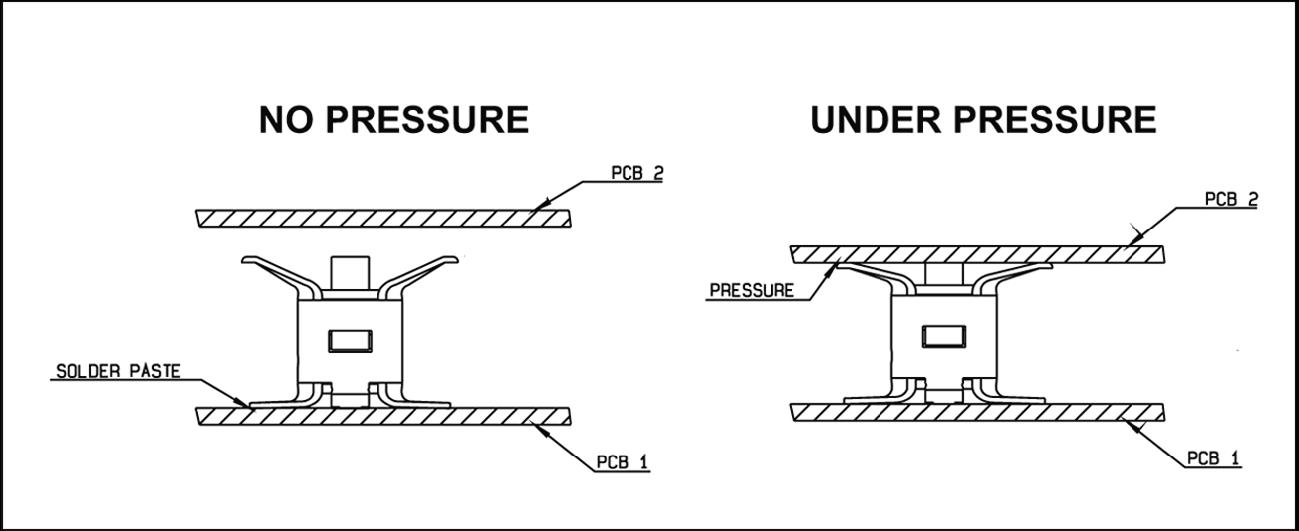
ASSEMBLY INSTRUCTIONS
M01 SOLDERING PATTERN
Metallization
R107 064 080
Land for solder paste (area free of vamish)
CONTACT PATTERN
Metallization
Contact area (area free of any surface contaminant)
R107 064 070 R107 064 080
18-16 | BR2/TYPE 43/UHF/IMP/IMP-MAX/UMP SIMPLIFICATION IS OUR INNOVATION Visit www.radiall.com for more information
PART NUMBER HEIGHT (MM) PACKAGING REEL DIMENSIONS A (MM) ASSEMBLY INSTRUCTIONS
2 Reel of 3500 330 M01
Reel of 100 180 PART NUMBER
R107
PART NUMBER
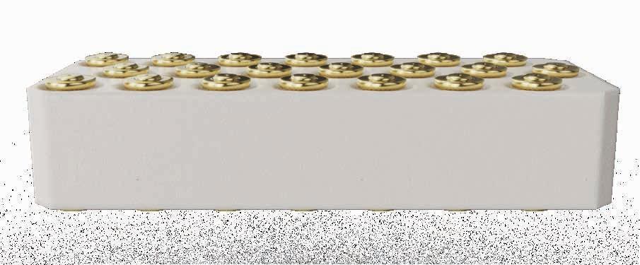
RECEPTACLE PACKAGING
PROCEDURE FOR USE OF SMT NOZZLE FOR RECEPTACLE
The following pick and place equipment and associated nozzles were successfully tested for the IMP:
A) FUJI: QP-242/MODULE TYPE QP-242 IMP MOUNT MODULE NAME: TYPE BI-612 IMP NOZZLE PART N°: I-S12B-013-100 (NOZZLE PIE 1 3)
B) PANASONIC: MSF type machine NOZZLE PART N°: 10 807 GH 810
For other equipment, please contact your supplier to define equivalent nozzles.
BR2/TYPE 43/UHF/IMP/IMP-MAX/UMP | 18-17 SIMPLIFICATION IS OUR INNOVATION Visit www.radiall.com for more information IMP
IMP H2
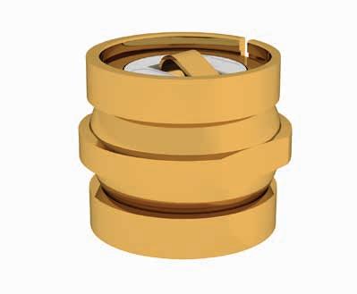
IMP-MAX
INTRODUCTION
IMP-MAX is famous for its extremely small board spacing, which can reach the lowest 2mm in the industry, and has a good application market in replacing multi-layer boards and minimizing equipment height, which will bring easy process and easy test value for customer�
FEATURES & BENEFITS
• Minimum board spacing solution
• Excellent isolation performance
• Mature application
APPLICATIONS
• Interconnection between extremely small board space
• Internal connection in low height module
18-18 | BR2/TYPE 43/UHF/IMP/IMP-MAX/UMP SIMPLIFICATION IS OUR INNOVATION Visit www.radiall.com for more information
IMP-MAX
CHARACTERISTICS
TEST / CHARACTERISTICS
ELECTRICAL CHARACTERISTICS
VALUES / REMARKS
MECHANICAL & ENVIRONMENTAL CHARACTERISTICS
Spring Force 4 N Typical @ 2 mm
Mating Life 20 Cycles Mini
Operation Temperature -40 / +105 ºC
PART NUMBER WORKING HEIGHT CONTACT TYPE R107 922 000 2 mm SMT at One Side and Elastically Contacted at Another Side
BR2/TYPE 43/UHF/IMP/IMP-MAX/UMP | 18-19 SIMPLIFICATION IS OUR INNOVATION Visit www.radiall.com for more information
Range DC - 6GHz VSWR 1.1 Typical @ DC - 3 GHz, 1.2 Typical @ 3 - 4 GHz, 1.3 Typical @ 4 - 6 GHz Isolation -70 dB @ 1 7 - 3 8 GHz Typical (Center to Center Distance 10 mm)
Frequency
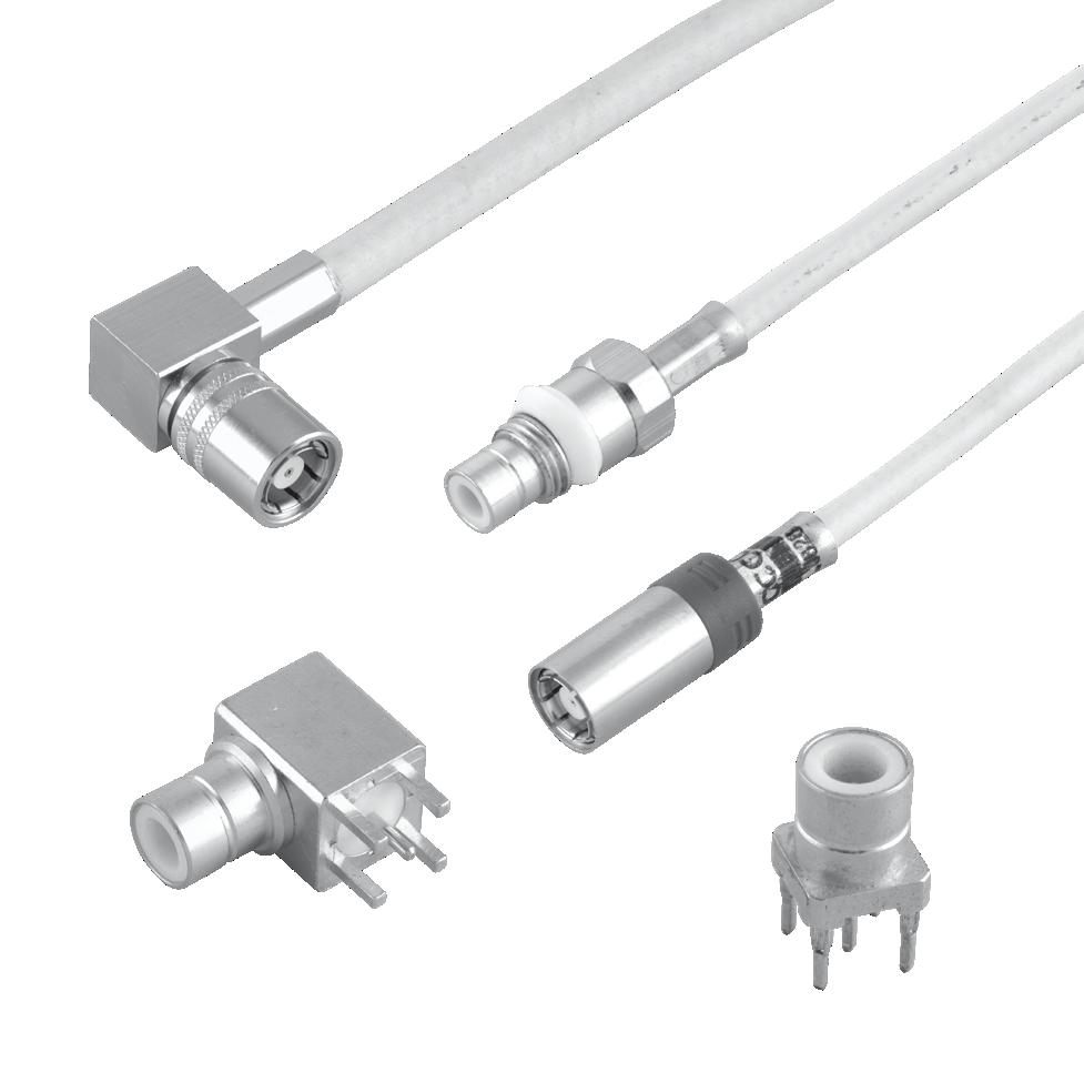
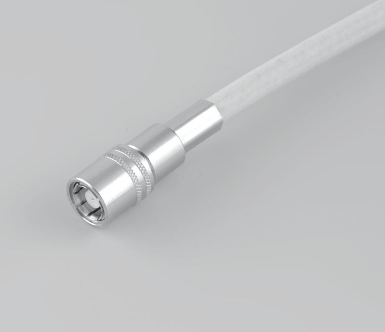
RECEPTACLES, PIGTAILS & CABLE ASSEMBLIES
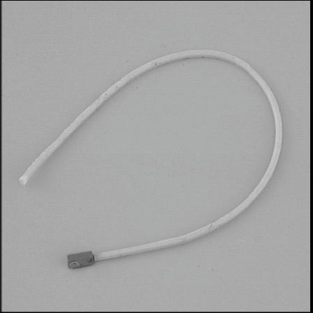
PIGTAILS
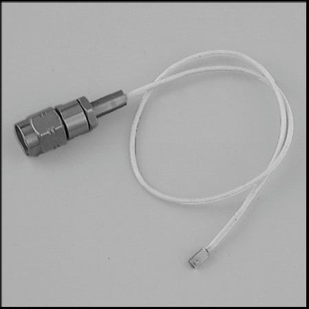
BETWEEN SERIES CABLE ASSEMBLIES
Lock Lock
1
2
FIG. 2
18-20 | BR2/TYPE 43/UHF/IMP/IMP-MAX/UMP SIMPLIFICATION IS OUR INNOVATION Visit www.radiall.com for more information
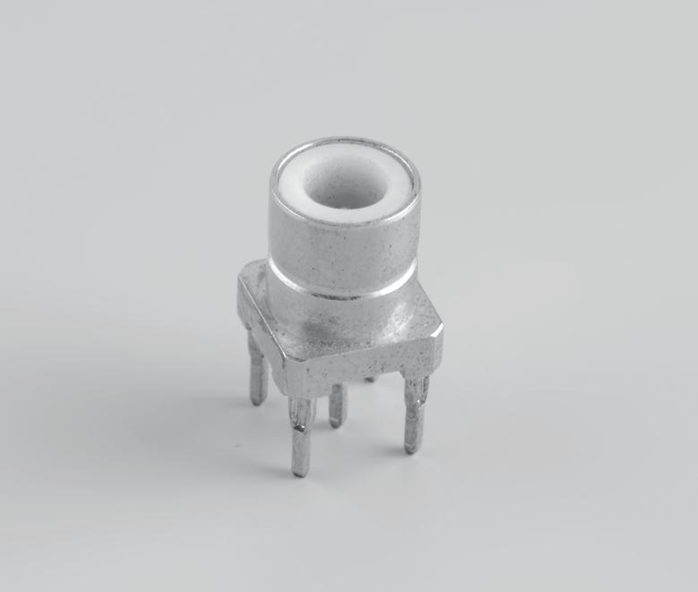
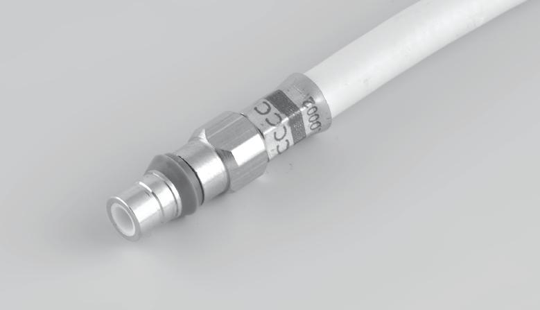
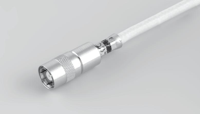
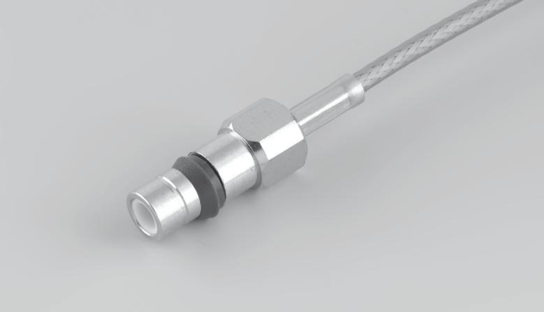
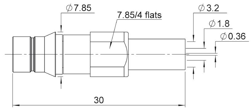
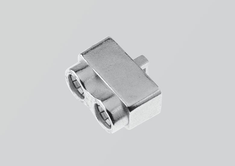
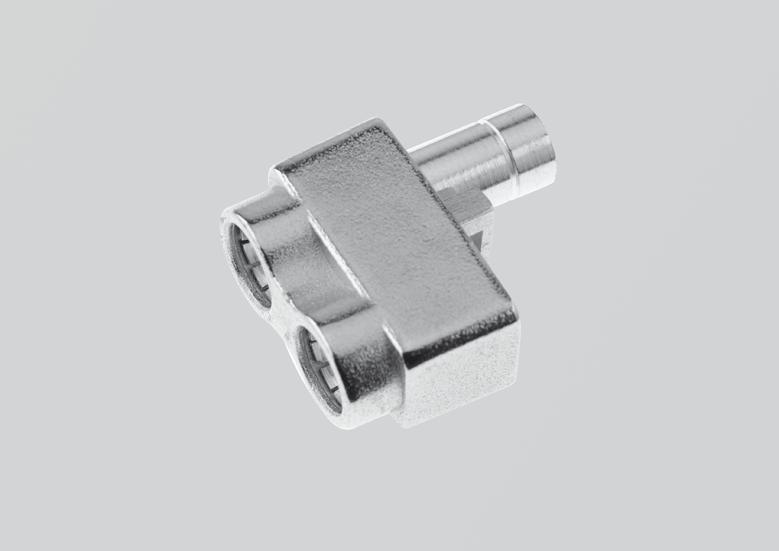
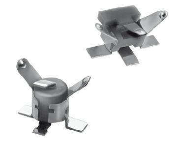
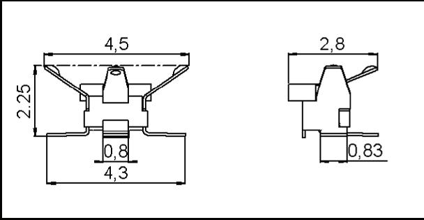
UMP
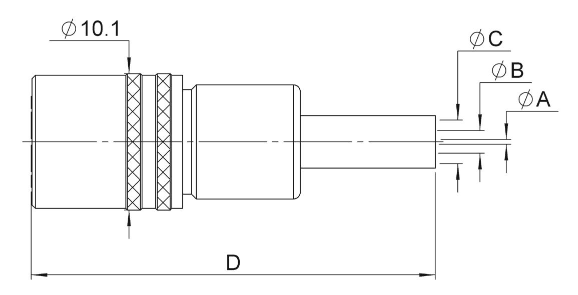
UMP TYPE PART NUMBER DIMENSIONS (MM) FINISH PACKAGING REEL DIMENSIONS (MM) ASSEMBLY INSTRUCTIONS A B C H2 R107 003 010 3 6 2 2 05 Gold 100 Pieces 180 M02 H3 R107 303 040 5 5 3 2 95 CABLE CABLE GROUP UMP TYPE MATING TYPE PART NUMBER FIG. DIMENSIONS (MM) PACKAGING A B C291 050 066 1/50/S H2 Lock R285 020 202 1 1 74 4 100 Pieces Snap-on R285 020 212 2 1 65 C291 170 017 2 6/50/S H3 Lock R285 020 401 1 2 84 CABLE CABLE GROUP UMP TYPE MATING TYPE PART NUMBER FIG. SERIES PACKAGING C291 050 066 1/50/S H2 Lock R285 025 202 1 UMP/SMA 20 Pieces Snap-on R285 025 212 2 C291 170 017 2 6/50/S H3 Lock R285 025 401 1
FIG. 1
FIG.
FIG.
Snap-on Snap-on
UMP
TOOLS & ACCESSORIES
PRODUCTION LINE TEST ADAPTER: UMP - SMA FEMALE (TO BE USED WITH LOCK AND SNAP PIGTAILS ONLY)
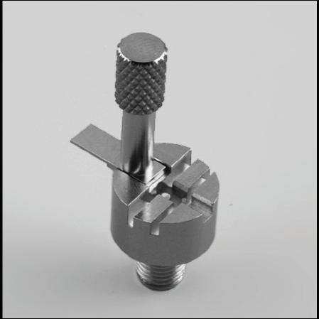
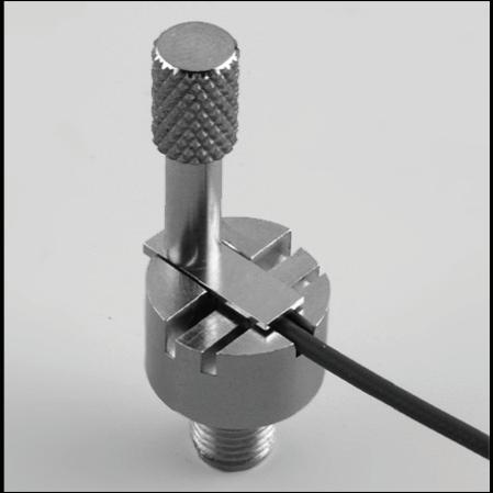
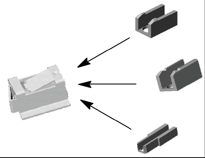
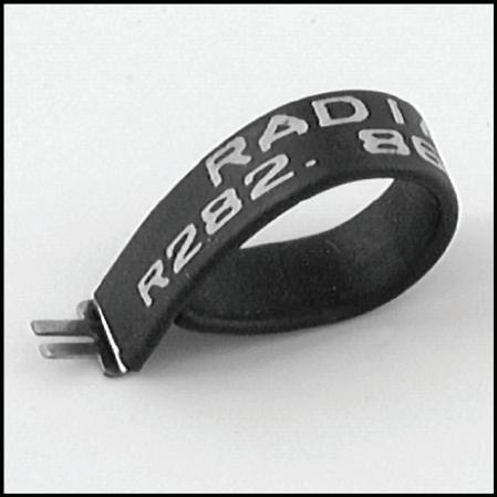
EXTRACTION TOOL (FOR LOCK VERSION ONLY)

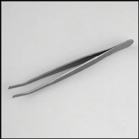
INSERTION TOOL (OPTIONAL)
203 020 For measurement and test purposes � Packaging: Unit
The 2 disconnection tools allows axial and lateral disconnections depending on the occupied space on the PCB �
This optional tool allows you a more precise connection in a limited space�
PACKAGING: UNIT
BR2/TYPE 43/UHF/IMP/IMP-MAX/UMP | 18-21 SIMPLIFICATION IS OUR INNOVATION Visit www.radiall.com for more information
PART NUMBER CONNECTOR HEIGHT (MM) PACKAGING R107 009 901 H 2 Unit R107 009 903 H 3 PART NUMBER PHOTO NOTE TO DISCONNECT PACKAGING R282 867 020 1 Axial Disconnection H 2 10 Pieces R282 867 030 2 Lateral Disconnection H 3 PART NUMBER R282
PHOTO 1 PHOTO 2
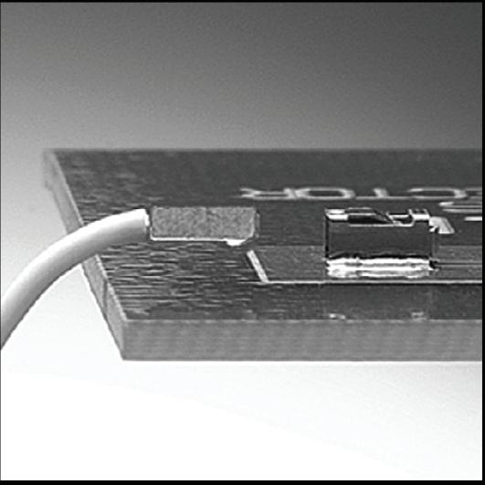
ASSEMBLY INSTRUCTIONS
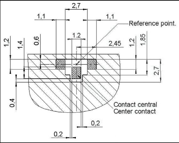
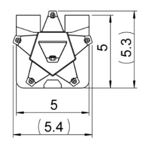
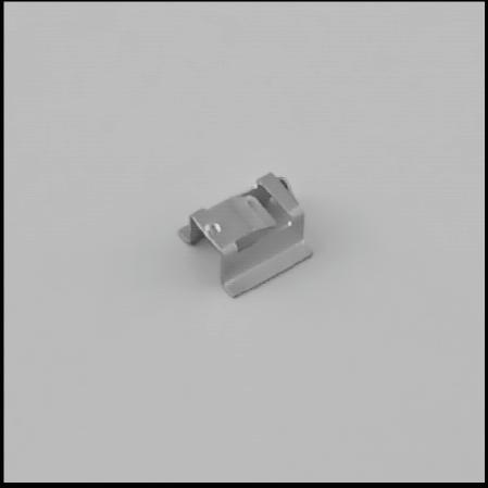
UMP M02
RECEPTACLE SOLDERING PATTERNS FOR COPLANAR LINE
H2 Type Receptacle
PART NUMBER
R107 003 010
H3 Type Receptacle
R107 303 040
SMT NOZZLE
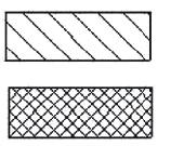
Gold over Nickel prefered for solder paste
Gold can be replaced by tin lead (see test report SC2000 02 6587)
Gold over Nickel contact area free of any surface contaminant
Ground + varnish
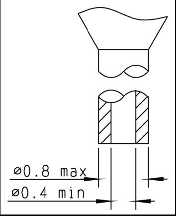
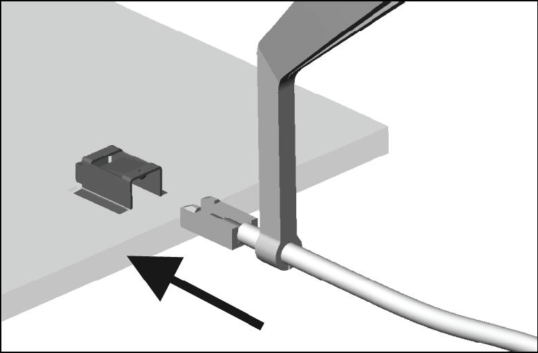
Automated pick and place machines use standard tooling to peel the antistatic film off. Sometimes the "A" dimension of this tool is shorter than the overall "B" width between the two legs of the receptacle There is therefore a risk for the two legs being deformed while they pass through the tool during the suction operation. The user must then widen the "A" dimension of the peeling tool.
18-22 | BR2/TYPE 43/UHF/IMP/IMP-MAX/UMP SIMPLIFICATION IS OUR INNOVATION Visit www.radiall.com for more information
PART NUMBER
PCB THICKNESS (MM) COPLANAR LIGNE A (MM) 0� 8 0�183 1 0 0 190 1 2 0 195 1�6 0� 20
INTERFACE
C DIA 1 31 1 36 052 054
D 2 95 3 05 116 120
E 7 6 7 9 299 311
F -0 05 0 15 002 006
G 0� 85 1� 55 �033 �061
H 1 55 1 65 061 065
CHARACTERISTICS
Bayonnet lock coupling with polarization
ELECTRICAL AND ENVIRONMENTAL CHARACTERISTICS
Withstanding
MATERIALS
BR2/TYPE 43/UHF/IMP/IMP-MAX/UMP | 18-23 SIMPLIFICATION IS OUR INNOVATION Visit www.radiall.com for more information
BR2
1.500 volts RMS, 50 Hz Maximum
3 5 Amp
> 10 5 MΩ Contact Resistance < 1 mΩ at 1 Amp Capacity
body < 1� 3 pF < 3 2 pF Frequency
DC - 0 5 GHz Temperature
-40
°C
Dielectric
Voltage Between pins Between pins and body
Intensity
Insulation Resistance Between pins Between pins and body
at 1 MHz Between pins Between pins and
Range
Range
+100
All
Other
Brass
Polyamide
Metal Parts Under Stress Beryllium Copper
Metal Parts
Insulators
and Diallyphtalate Gaskets Neoprene
LETTER MM INCH MIN MAX MIN MAX A DIA 10 93 11 09 430 437 B DIA 9 60 9 70 378 382 C DIA 8 79 9 04 346 356 D DIA 8 31 8 46 327 333 E DIA 8 09 8 15 319 321 F DIA 5 9 6 0 232 236 G DIA 1� 4 1� 45 �055 �057 H 2 95 3 05 116 120 I -0 1 0 8 - 004 031 J 5 � 3 5 �7 � 209 � 224 K 7 05 7 35 278 289 L 8 36 8 46 327 335 M 1 91 2 06 075 081 N 1 45 1 55 057 061 O 0 35 0 85 014 033 LETTER
INCH MIN MAX MIN MAX
MM
A DIA 9 78 9 91 385 390
B DIA 6 70 6 77 264 267
JACK PLUG
PLUGS & JACKS
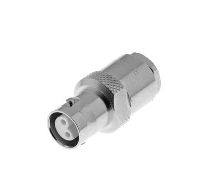
STRAIGHT PLUGS FOR ARMOUR TWINAXIAL CABLE
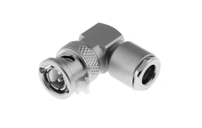
RIGHT ANGLE PLUG
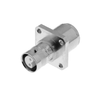
STRAIGHT JACKS
2
18-24 | BR2/TYPE 43/UHF/IMP/IMP-MAX/UMP SIMPLIFICATION IS OUR INNOVATION Visit www.radiall.com for more information BR2
CABLE GROUP DIA. PART NUMBER DIMENSIONS (MM) A Twinaxial 4 R605 004 000 4 6 Twinaxial 5 R605 005 000 5 6 Twinaxial 6 R605 006 000 6 6 CABLE GROUP DIA. PART NUMBER FIG. PANEL DRILLING NOTE Twinaxial 6 R605 206 000 1 P01R605 256 000 2 Square Flange CABLE GROUP DIA. PART NUMBER Twinaxial 6 R605 156 000
FIG.
1
FIG.
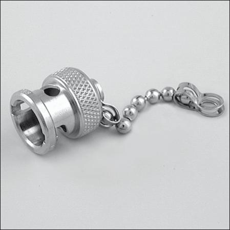
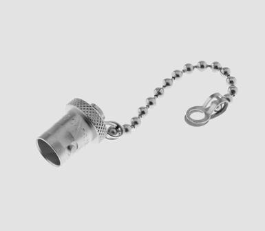
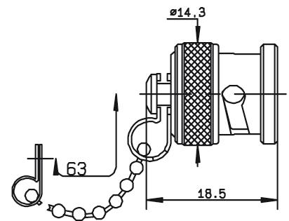
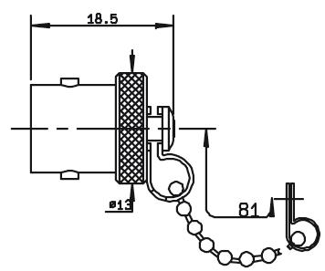
RECEPTACLES & CAPS
RECEPTACLES
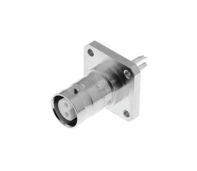
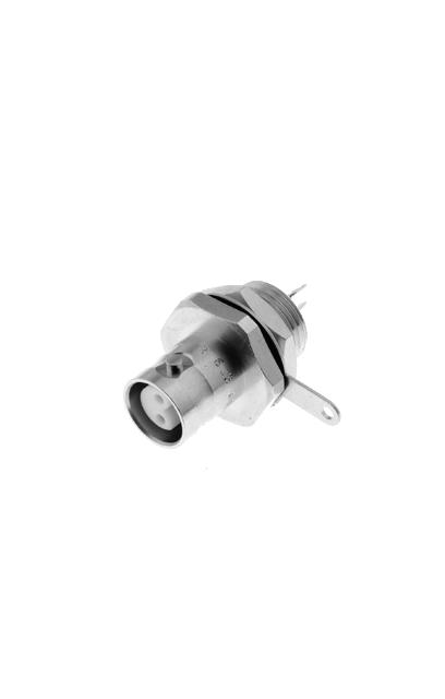
PCB RECEPTACLES
BR2/TYPE 43/UHF/IMP/IMP-MAX/UMP | 18-25 SIMPLIFICATION IS OUR INNOVATION Visit www.radiall.com for more information BR2
PART NUMBER FIG. PANEL DRILLING NOTE R605 400 000 1 P02 Square Flange R605 550 000 2 P04 Rear Fixing R605 550 020 Front Mounting R605 600 000 3 P05 Waterproof PART NUMBER FIG. NOTE R141 802 000 1 Male R141 812 000 2 Male with Chain R141 842 000 3 Female with Chain PART NUMBER PANEL DRILLING R605 440 000 P03
FIG. 1
FIG. 1
FIG. 2
FIG. 2
FIG. 3
FIG. 3
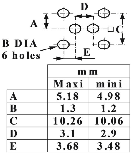
PANEL DRILLING
18-26 | BR2/TYPE 43/UHF/IMP/IMP-MAX/UMP SIMPLIFICATION IS OUR INNOVATION Visit www.radiall.com for more information
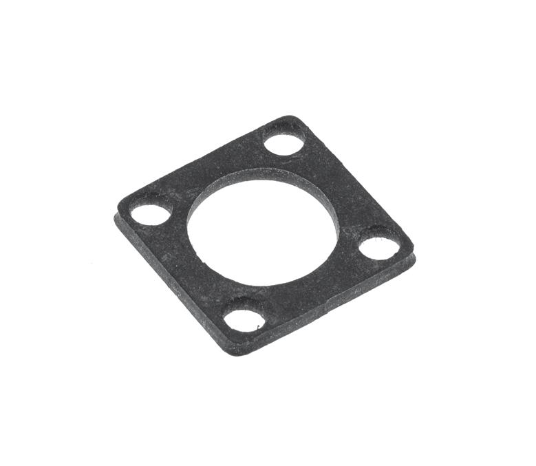
BR2 GASKET
R280 503
P01 P02 P05 P04 P03 mm M axi mi ni A (R. Mount) 11 .3 11 .2 A (F. Mount) 13 12 .9 B 2. 7 2. 6 C 12 .7 5 12 .6 5 B DI A 4 ho le s A DI A C mm Maxi mini A 11.3 11.2 B 2.7 2.6 C 12.75 12.65 B DIA 4 holes A DIA C
PART NUMBER
000
INTERFACE
A DIA 11 56 12 22 455 481
B DIA 16 00 - 630 -
C DIA 13 92 - 548 -
D DIA - 3 35 - 132
E DIA 3 912 4 013 154 158
F - 11 10 - 437
G - 9 91 - 390 H 8 �76� 335I 1 19 4 27 047 168 J 0 00 - 000 -
CHARACTERISTICS
A DIA 11 56 12 22
DIA 14 00 14 25 551
C 11 10 - 437D 7 87 - 310E 1 02 - 040F 0 03 - 001G 1 19 1 96 047 077
TEST / CHARACTERISTICS VALUES / REMARKS
ELECTRICAL CHARACTERISTICS
Impedance
Maximum Frequency Range
Test Voltage (At Sea Level)
Working Voltage (At Sea Level)
Insulation Resistance (Under 500 V)
MECHANICAL CHARACTERISTICS Mating Cycles
ENVIRONMENTAL CHARACTERISTICS Temperature Range • PTFE • Bakelite • Styramic -55°C to + 155°C
MATERIALS
to + 165°C
to + 70°C Salt Spray 48 Hrs
Contacts and Interfaces Heat Treated Beryllium Copper Other Parts Brass Insulator PTFE (T) - Bakelite (B) or Styramic (St ) Gaskets Neoprene or Silicone Rubber
Notes All dimensions are given in mm.
BR2/TYPE 43/UHF/IMP/IMP-MAX/UMP | 18-27 SIMPLIFICATION IS OUR INNOVATION Visit www.radiall.com for more information
UHF
50Ω
500 MHz
2000 V rms - 50 Hz
750 V
•
•
5 mΩ max 5 mΩ max
≤ 5 GΩ Contact Resistance
Center Contact
Outer Contact
500
-40°C
-40°C
LETTER
INCH MIN MAX MIN MAX
MM
LETTER
INCH MIN MAX MIN MAX
JACK
MM
455 481 B
561
PLUG
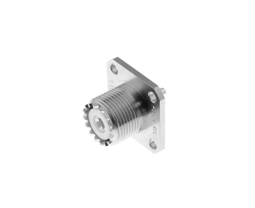
PLUGS, RECEPTACLES & ADAPTER
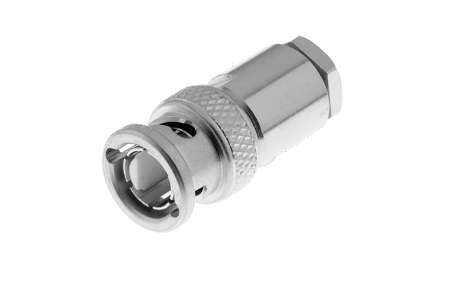
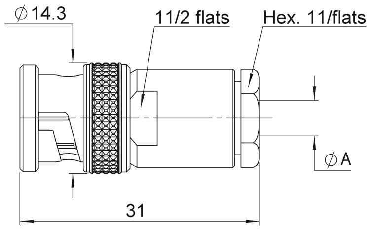
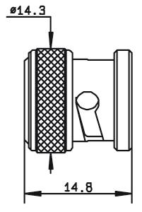
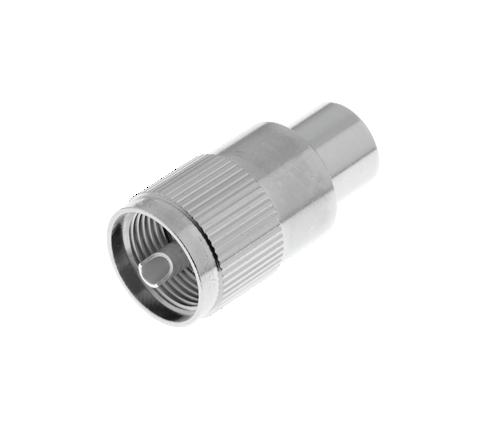
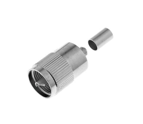
STRAIGHT PLUGS
18-28 | BR2/TYPE 43/UHF/IMP/IMP-MAX/UMP SIMPLIFICATION IS OUR INNOVATION Visit www.radiall.com for more information UHF
CABLE GROUP CABLE GROUP DIA. PART NUMBER FIG. NOTE RG213 /
/ RG11 / RG12 / RG144 10/50+75Ω R155 003 000 1 Insulator: PTFE R155 005 000 2
RG393
FIG. 1
FIG. 2
FIG. 1
PART NUMBER FIG. PANEL DRILLING NOTE R155 405 000 1 P01 Square Flange - Solder Pot - Insulator: PTFE R155 560 000 2 P02 Bulkhead - Solder Pot - Insulator: PTFE
FIG. 2