
Section 4 Table of Contents
Coaxipack 2
INTRODUCTION
The Coaxipack 2 series has been designed in accordance with the IEC 61076-4-104 (standard 2mm geometry system)
Coaxipack 2 provides high density coaxial connectors aimed at high speed and space saving applications� The Coaxipack 2 series is available in 50Ω and 75Ω.
APPLICATIONS
50Ω RANGE
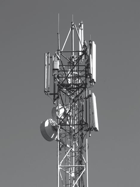
• Telecom / Datacom (Transmission equipment, Satellite Communication Systems, Base station)
• Medical
• Networking industry
• Instrumentation
75Ω RANGE
• High speed data network
• Digital Broadcast System (Routers, Switching and Control Systems, Monitoring and Signal Measurement, Encoders etc���)
FEATURES AND BENEFITS
Coaxipack 2 combines high performance miniature coaxial connectorswith the convenience, compactness and cost effectiveness of 2mm metric systems.
FEATURES
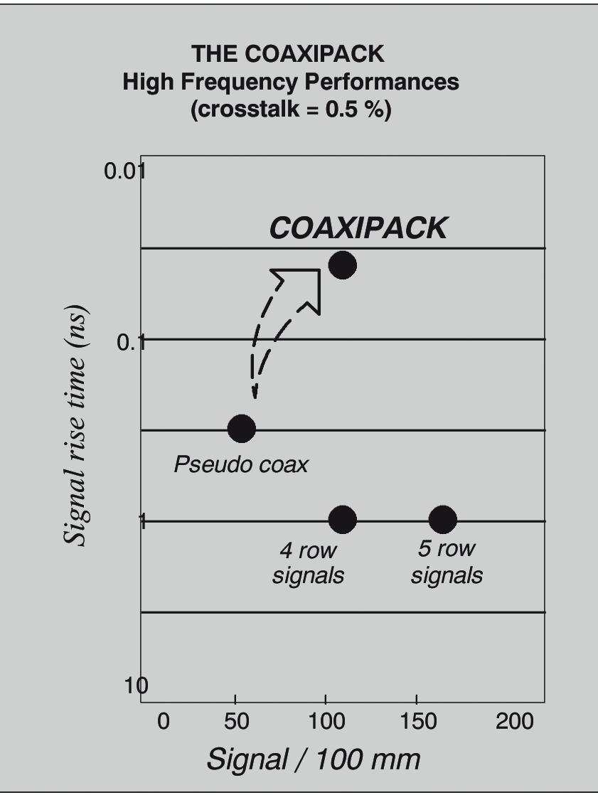
• Excellent for coaxial signal transmission: Low crosstalk, low signal distortion, high level of EMI/RFI shielding
• High speed performance: Minimum reflection and propagation delay, sub-nanosecond rise time capabilities
• Ruggedized for a variety environments: Industrial applications, humidity, shock, vibration…
BENEFITS
• Space savings on PCB, reduced PCB routing complexity and supplies adequate spacing for high speed routing
• Stackable with other 2mm metric modules (ex: power, signal) from most manufacturers�
• Maximum flexibility in system architecture due to Coaxipack’s modular design-system designers are able to upgrade designs and add new functions without having to adopt major changes in the hardware configuration.


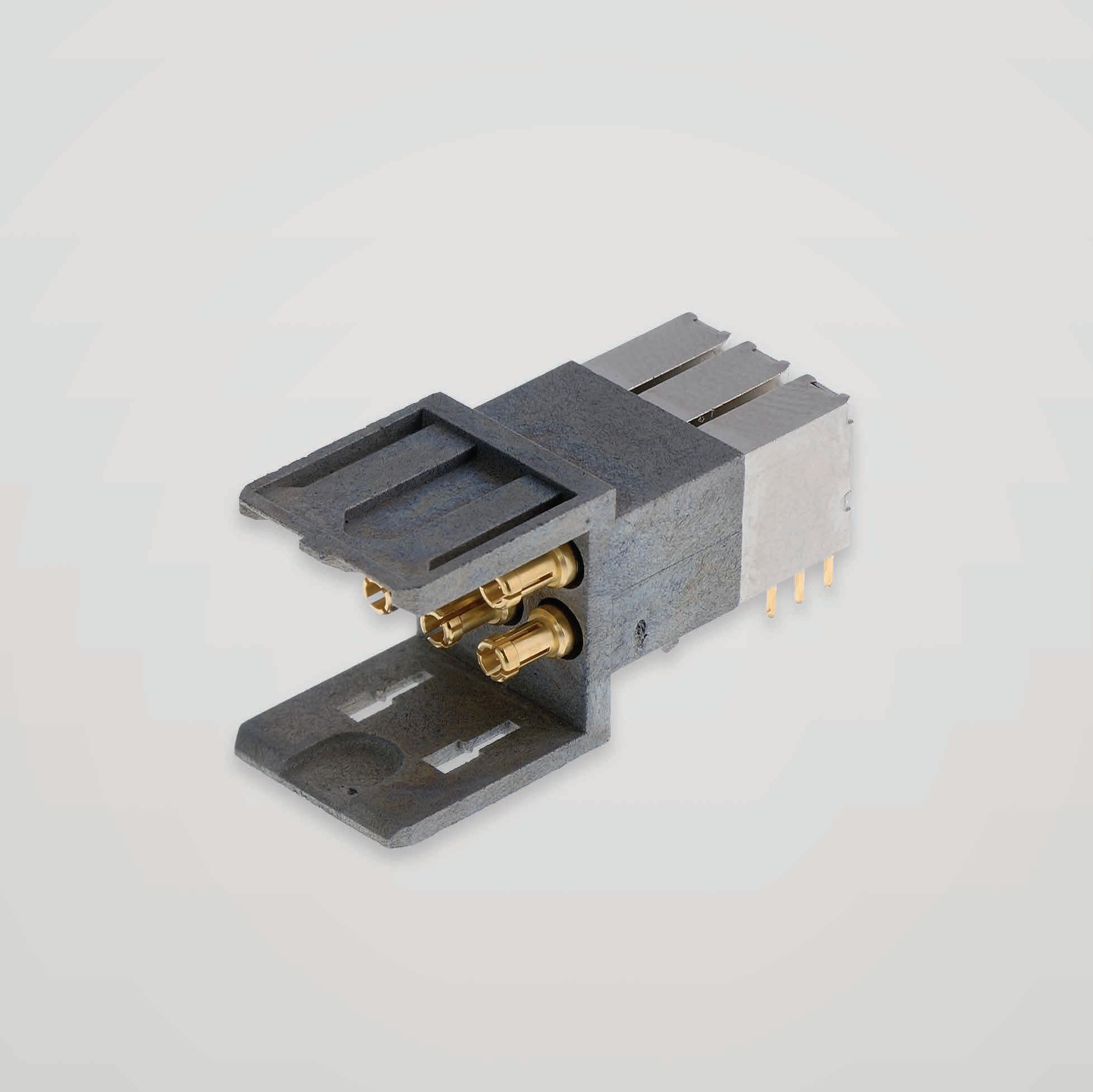
MODULE
• Radiall offers a large range of pre-assembled modules. The term ”module” is used for Coaxipack 2 connector mounting on board configuration.
• One module combines a housing including one or more inserts The number of inserts depends on the required configuration, up to 6 contacts.


Depending on the part number, one insert is made of one or two coaxial contacts
1 INSERT = 1 CONTACT
1 INSERT = 2 CONTACTS
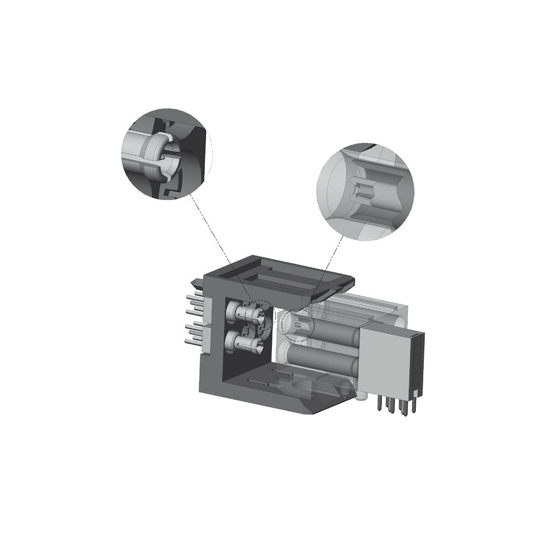
Radiall offers a standard kit including straight female insert and housing which fully complies with the IEC 61076-4-104.
Robust guidance and mating tolerances with reinforced interface provides a perfect alignment without any risk of loss of contact�
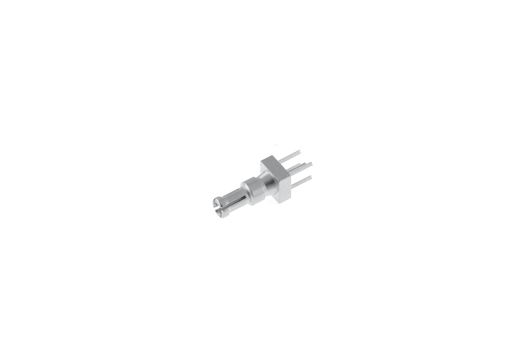
• Male: New chamfers on outer contact and new radius on center contact for improved guidance
• Female: New chamfered and extended insulator prevents any misalignment in very high density applications
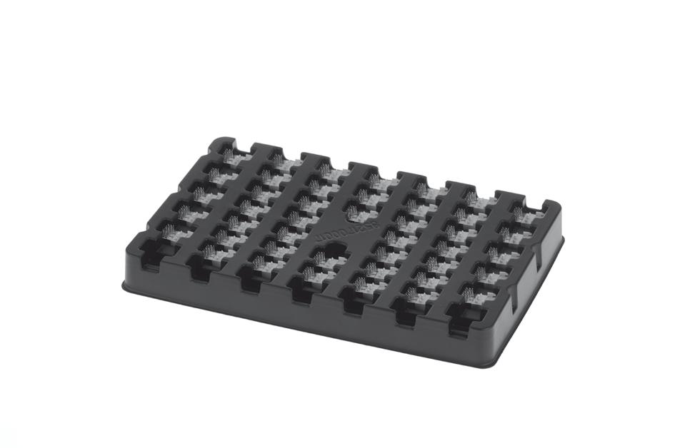
• Packaging: Improved design of packaging to secure the connectors and prevent any damage during the transportation or handling All connectors are shipped in a tray for safety during transportation and an added convenience during the manufacturing process�
ORDERING GUIDE
• Connector Choice
Radiall offers either ready to use modules (housing + inserts) or cable assembly kits.
• Shielded Connectors
Additional choices with two ways of plating to improve the shielding level:
(1) Addition of metal plates to the plastic housing
(2) Metallization of the plastic housing
Coaxipack 2
CHARACTERISTICS
TEST / CHARACTERISTICS
ELECTRICAL CHARACTERISTICS
Frequency Range
VALUES / REMARKS
DC-3 GHz (Optimized) - (Working Range up to 6 GHz) Impedance 50Ω and 75Ω
V.S.W.R Mated Pair for
• PCB Modules
• Straight Female - Cable Assembly
• Straight Male - Cable Assembly
Insertion Loss Mated Pair
0 2 dB Typical from 0 to 3 GHz
RF Leakage -35 dB at 3 GHz
Voltage Rating
Dielectric Withstanting Voltage
Insulation Resistance
Contact Resistance
Center Contact
Outer Contact
Rise Time Degradation (Corrected for Board Effects) at 300ps
Difference in Propagation Delay between Shortest and Longest Line
V
V
5000 MΩ
ps Near End Crosstalk at 300ps
MECHANICAL CHARACTERISTICS
Mating Cycles
Insertion Force
5 N
Extraction Force 2 2 N
Contact Density
ENVIRONMENTAL CHARACTERISTICS
MATERIALS
PLATING
2 to 6 Contacts per Module
60 Contacts per 120 mm x 16 mm
Temperature Range -25 / +125 °C
Housing
Liquid Crystal Polymer (LCP) Glass Filled Bodies & Contacts
Brass or Bronze (See Technical Data Sheet for Details) Insulators PTFE / PEEK Spring Contacts Beryllium Copper
Coaxial Contacts NPGR
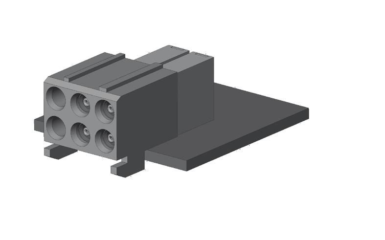
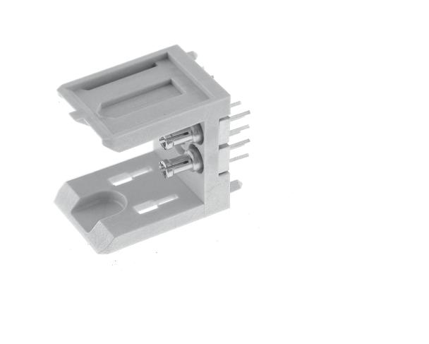
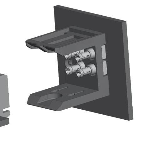
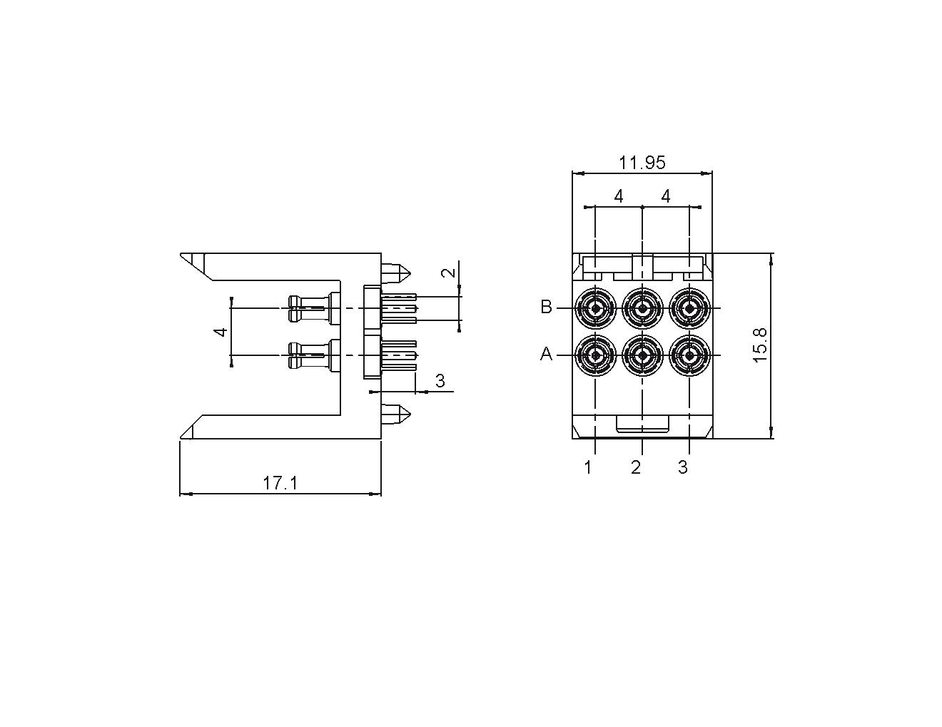
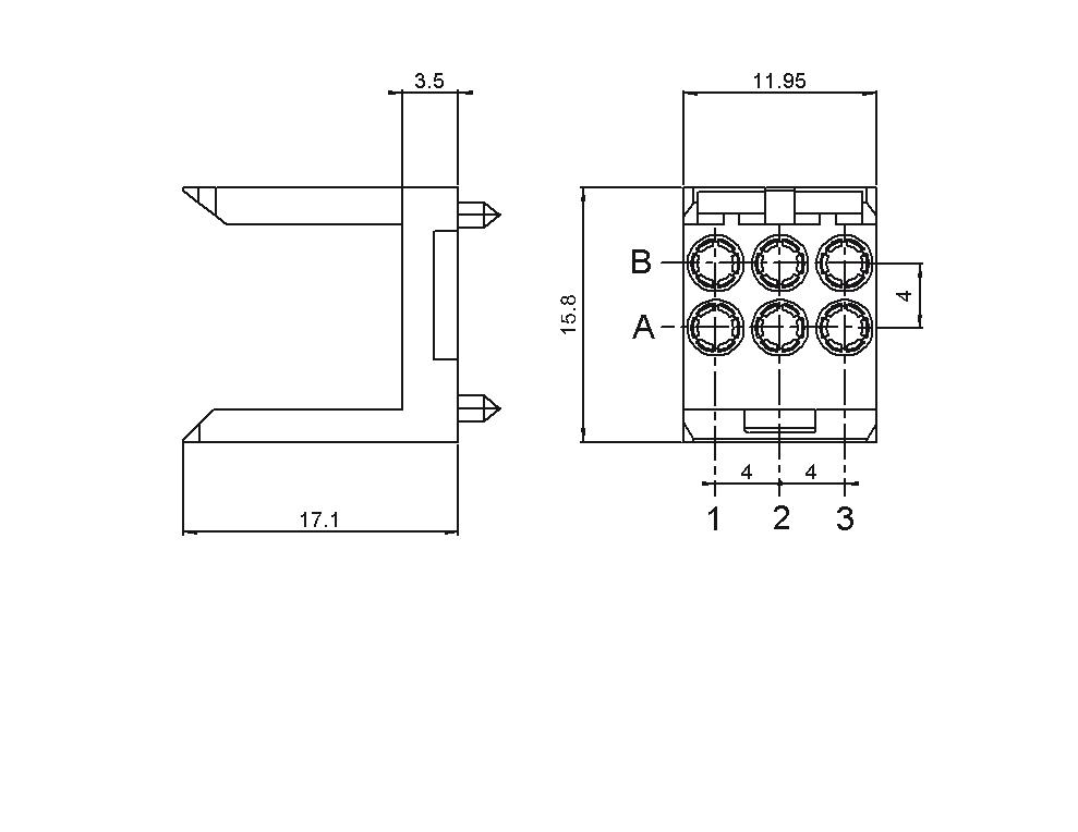
PCB MODULES
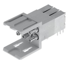
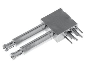
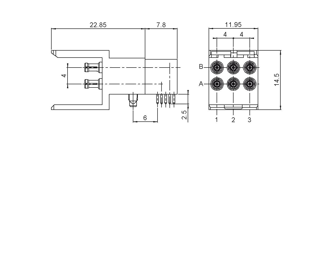
RIGHT ANGLE FEMALE PCB MODULES (50Ω)
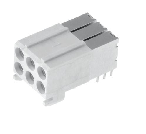
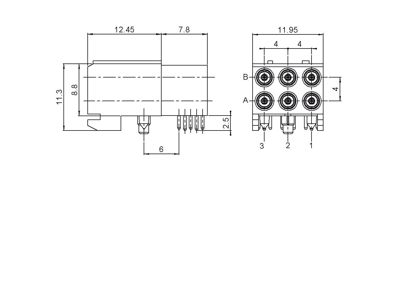
(Not Sold Separately)
Coaxipack 2
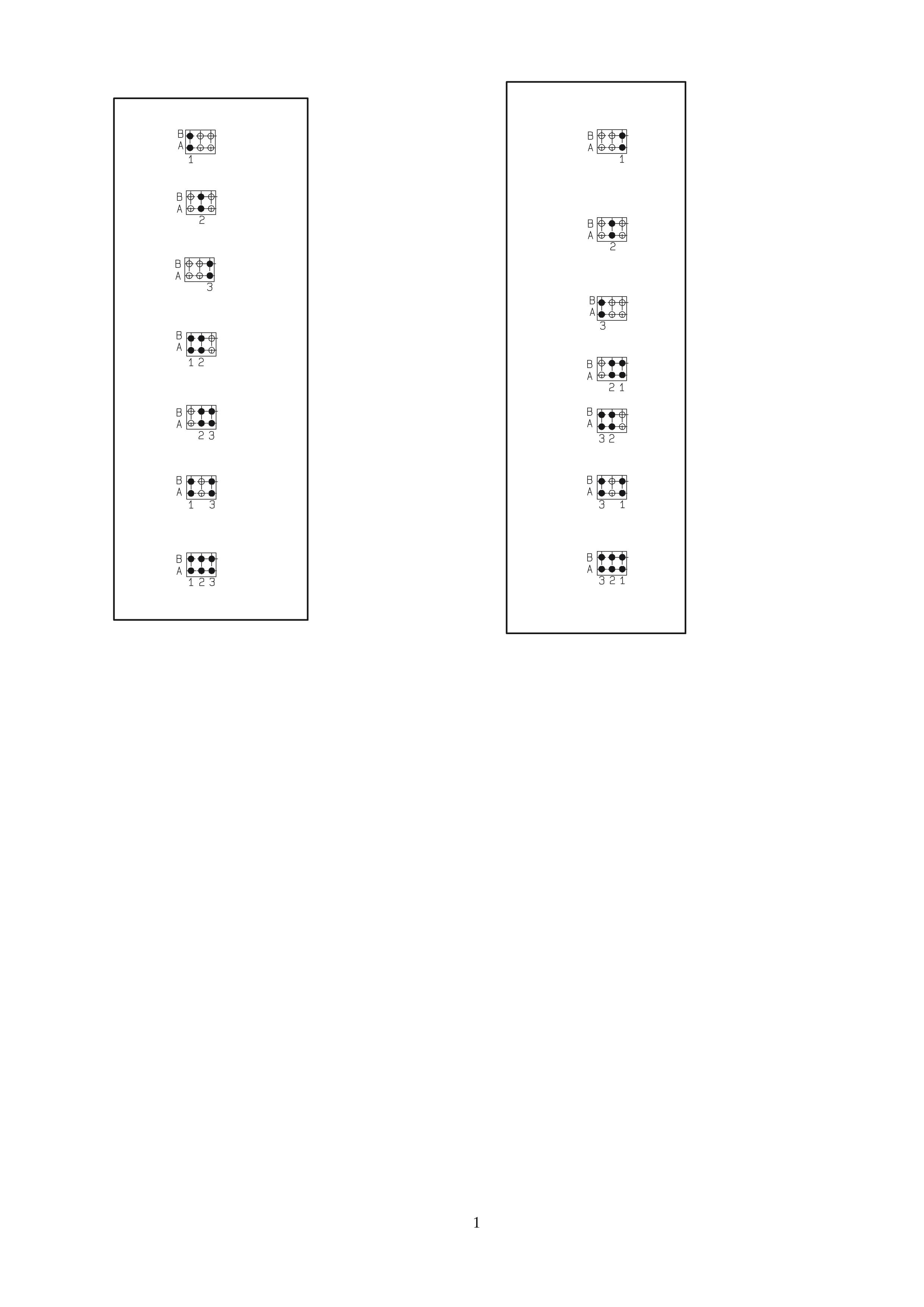
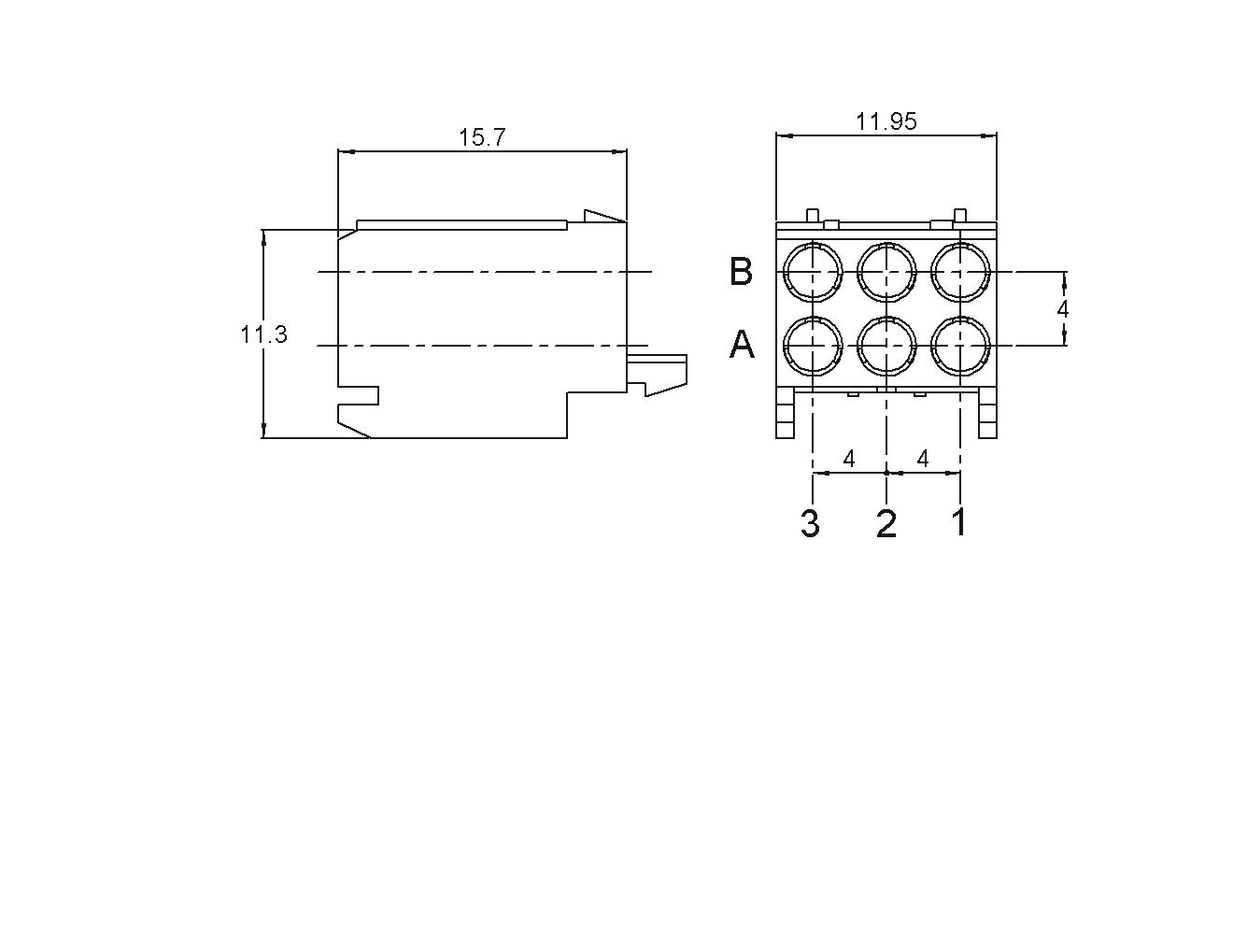
STRAIGHT MALE PCB MODULES (50Ω)
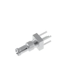
Recommended PCB thickness: 2 mm max
NUMBER OF CONTACTS POSITION
Coaxipack 2
STRAIGHT MALE PCB MODULES (50Ω)
(Not Sold Separately)
Notes
1. Housing is available in shielded version. For specific request, please consult sales
2. With shielded version.
Coaxipack 2
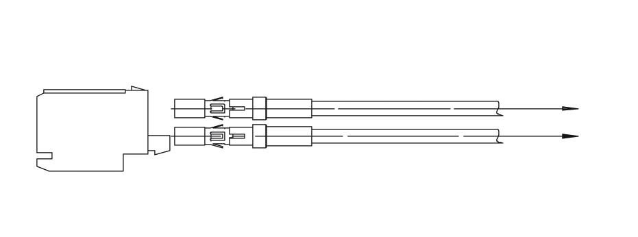
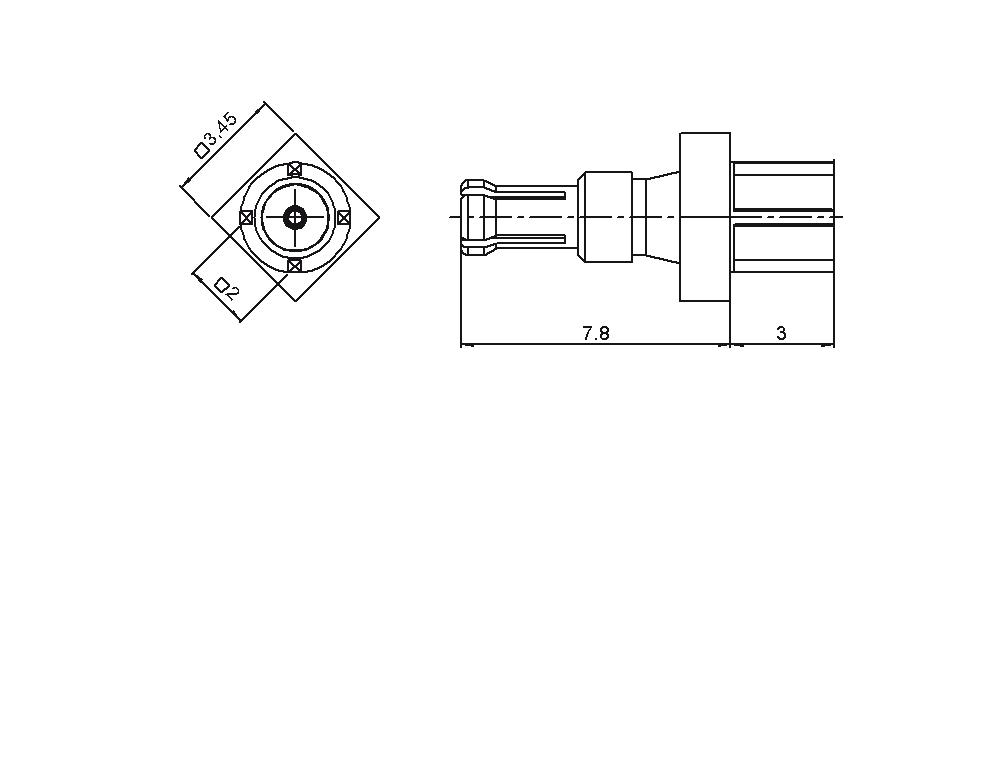
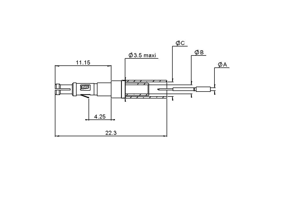
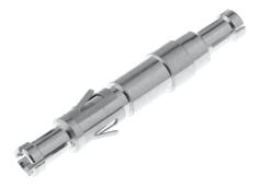
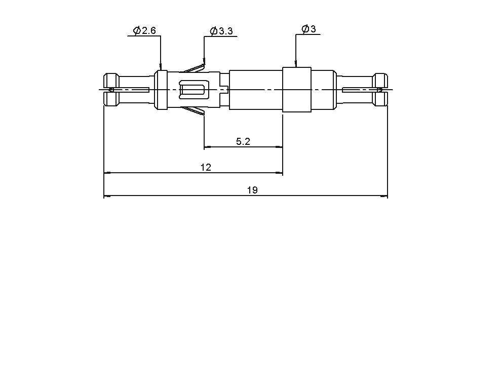
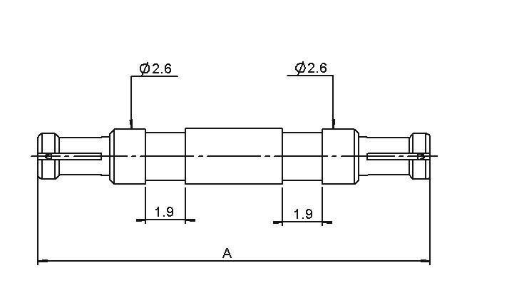
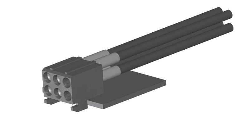
FEEDTHROUGH MALE CABLE ASSEMBLY
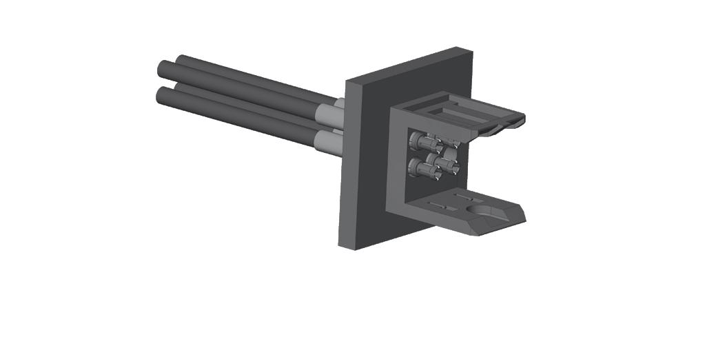
STRAIGHT MALE HOUSING
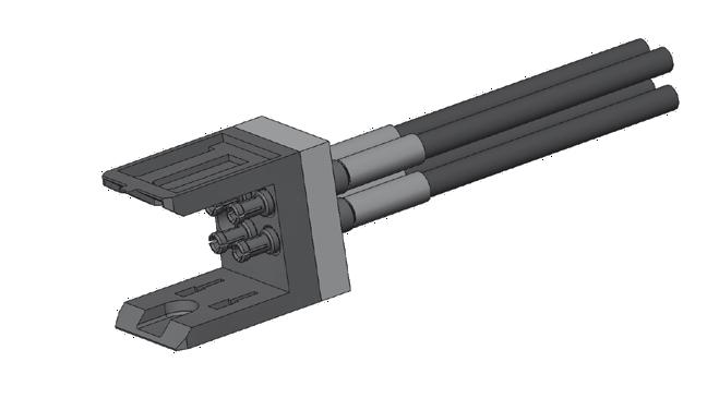
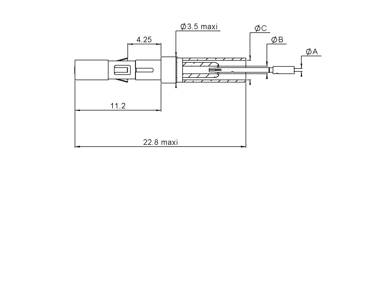
STRAIGHT MALE REMOVABLE INSERTS, FULL CRIMP TYPE
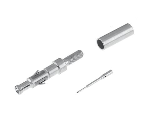
7 DIFFERENT POSSIBLE CONFIGURATIONS CABLE GROUP CABLE
PART NUMBER NOTE
R694 261 906 For Removable Inserts (Not Included)
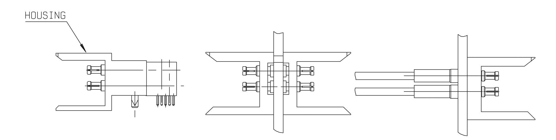
FEEDTHROUGH MALE - MALE ADAPTER KITS
Panel Thickness (see table)
R694 261 906 + R199 001 733
FOR REMOVABLE INSERT (50Ω) FOR NON REMOVABLE INSERT (50Ω)
2 DESIGNATION

Notes
1. Kits including housing and inserts are available. Please consult sales.
2. Other length and PCB thickness available upon request: please consult sales.
Coaxipack 2
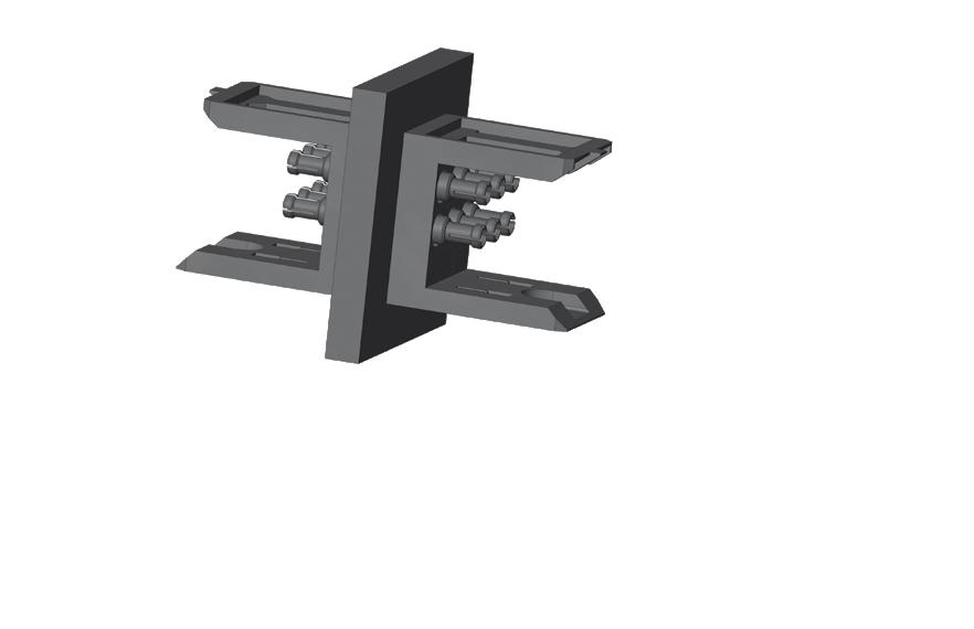
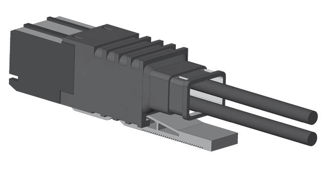
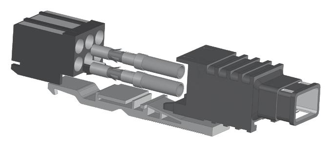
CABLE ASSEMBLY
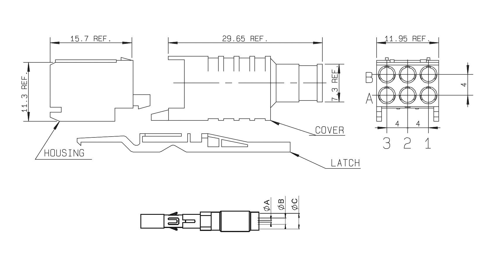
Each cable assembly consists of:
• One housing
• One cover
• One latch
• One or several inserts corresponding to customer’s configuration
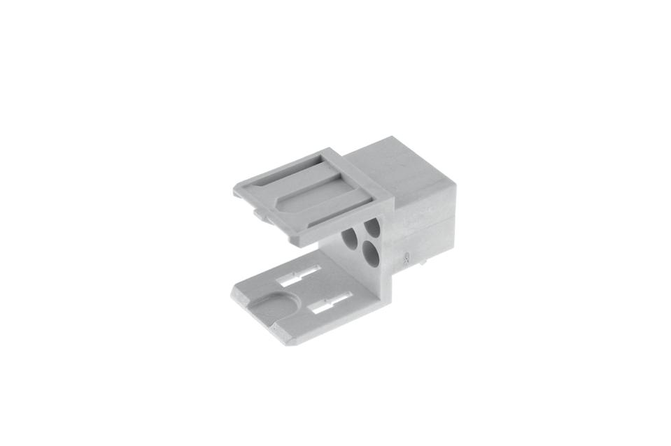
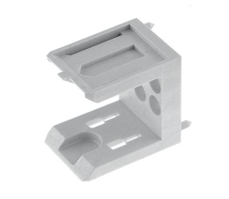
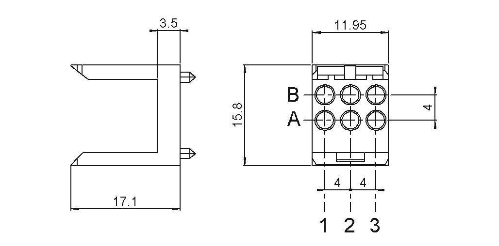
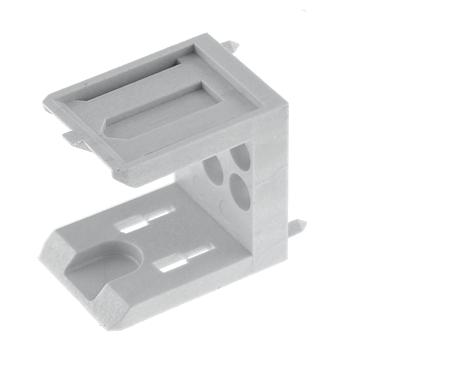
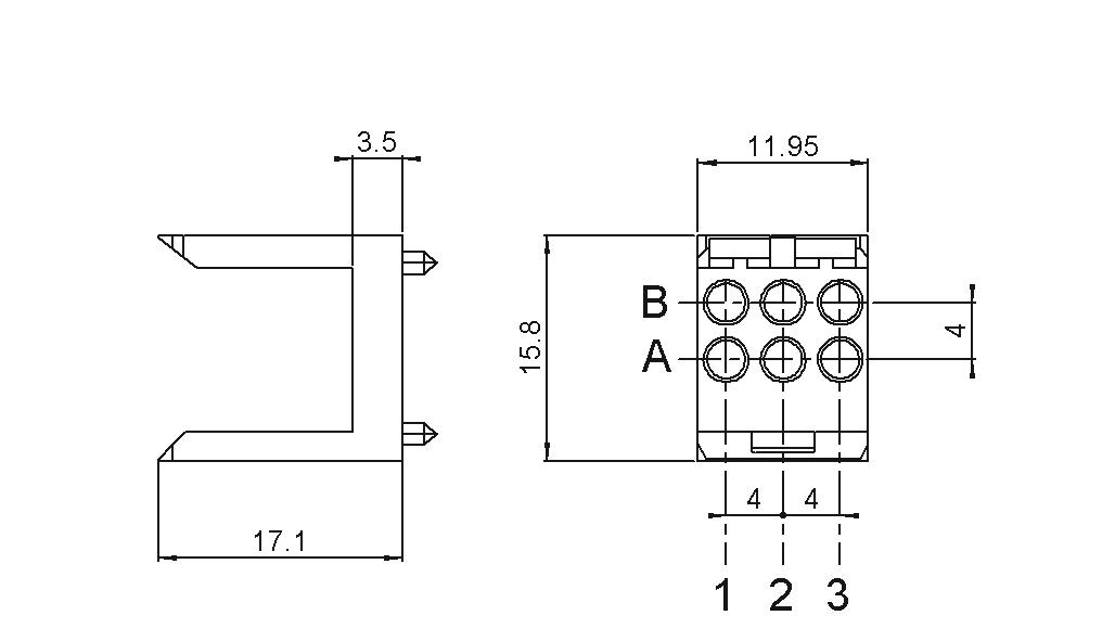
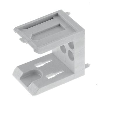
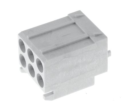
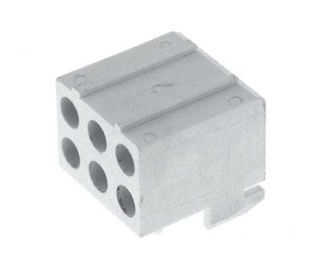
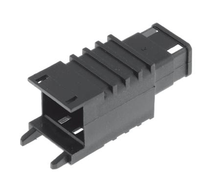
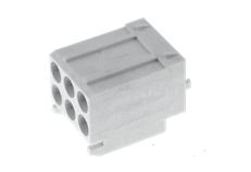
HOUSING (TWO TYPES OF HOUSING FOR STRAIGHT FEMALE CABLE ASSEMBLY KIT ARE OFFERED)
TYPE 1 Available for 50Ω and 75Ω
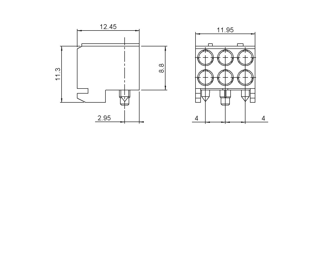
TYPE 1: HOUSING FOR FEMALE INSERTS
COVER (TYPE 1 ONLY) COVER HOUSING INSERTS LATCH
TYPE 2 Available for 50Ω and 75Ω
PART NUMBER
R694 262 056
Straight Inserts (see page 5-14) for 50Ω: R199 001 003 or R199 001 023 for 75Ω: R199 001 053
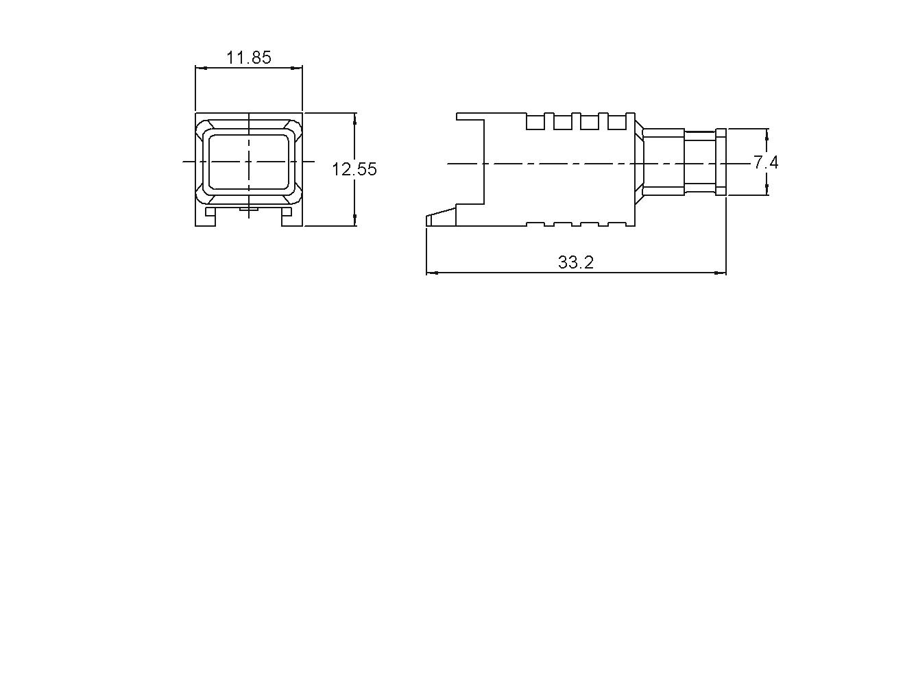
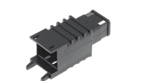
TYPE 2: HOUSING FOR FEMALE INSERTS WITH PRESS - IN FIXING STUD (FOR PANEL AND PCB MOUNTING)
PART NUMBER
R694 262 906
Straight Inserts (see page 5-14) for 50Ω: R199 001 003 or R199 001 023 for 75Ω: R199 001 053
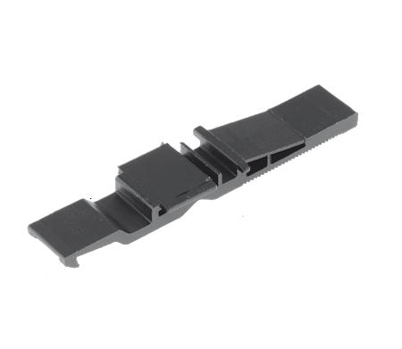
PART NUMBER
R280 420 010
Coaxipack 2
LATCH (TYPE 1 ONLY)
KIT: COVER + FEMALE HOUSING + LATCH (TYPE 1 ONLY)
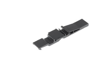
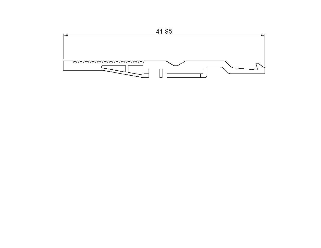
PART NUMBER R280 420 030
COMPOSED OF R694 262 056 + R280 420 010 + R280 420 030
STRAIGHT FEMALE REMOVABLE INSERTS, FULL CRIMP TYPE (TYPE 1 AND 2)
PACKAGING
PACKAGING
30 Pieces
NOTE
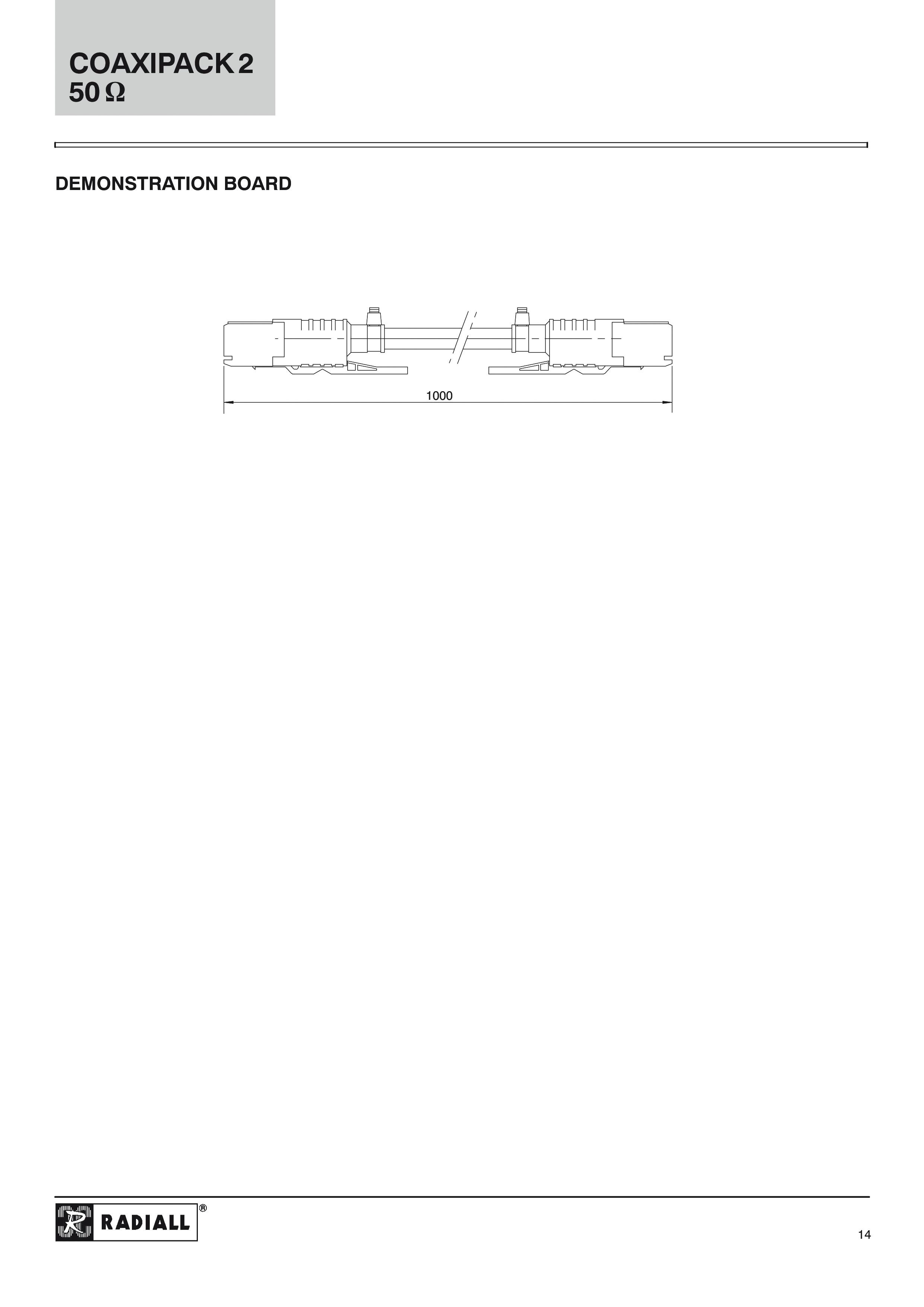
Can be used with Demonstration Board R299 400 020
Notes
1. Special configuration is available upon request. Please consult sales.
2. Other guide pin length available upon request. Please consult sales.
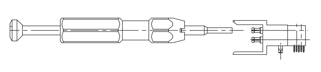
EXTRACTION PROCEDURES
U01 HOW TO USE TOOL R282 920 010
INSERTS
R199 001 203
R199 001 223
R199 001 733
1
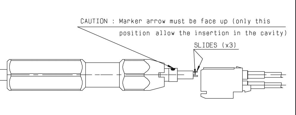
• Place the extraction tool as shown (upper coaxial contact only for twin coax) and push in axial direction into the housing until it stops
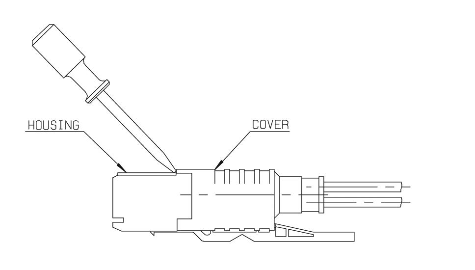
U02 HOW TO USE TOOL R282 920 100
KITS
R285 930 005
R694 252 507
R694 252 537
R694 252 557
1
• Use a screw-driver to remove the cover from the housing as shown�
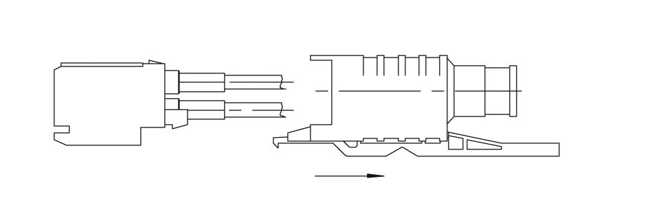
2
• Slide the cover along the cable
PRE-ASSEMBLED MODULES
251 115
R694 251 116
R694 251 117
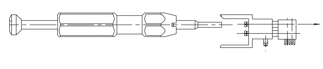
2
• Then press gently on the rod to remove the contact from the rear of the housing
INSERTS
R199 001 003
R199 001 023
R199 001 053
3
• Place the extraction tool (as shown) and push in axial direction into the housing until it stops
4
• Then press gently on the piston to remove the contact