AEP COAXIAL CONNECTORS
Full Line Catalog
RF COAXIAL CONNECTORS SIMPLIFICATION IS OUR INNOVATION
SIMPLIFICATION is our INNOVATION
Radiall is a community of dedicated individuals with a shared purpose: simplify life for all those who innovate. Our manufacturing expertise allows us to deliver lighter and smaller products that simplify implementation and drive performance. We recognize that simplification starts with us, but proves its true benefits when it reaches you.

TABLE OF CONTENTS SMP 5 Adapters 9 QCD 8 (Quick Connect-Disconnect) SMB/SMC/SLB 3 SSMB/SSMC/SSLB 4 Cable Terminations 7 SMA 2 75 OHM Series 6 MIL-QPL 1 Part Number Index 15 Tooling 14 Assemblies 13 TNC 12 Type N 11 BNC 10

DEFENSE
& RAIL SPACE TELECOM
& MEASUREMENT MEDICAL
AEROSPACE
INDUSTRIAL
TEST
OUR COMPANY
Since 1952, we have been enabling the future through collaboration with our customers. The results are a range of innovative and awardwinning products that customers trust for unrivaled repeatability and performance.
We are a global company with facilities around the world that specializes in manufacturing the highest-quality interconnect components to support the most demanding applications. At Radiall, you can rely on us to be the industry’s global market leader.
INDUSTRIES WE SERVE
For over 60 years, we have fostered relationships grounded in trust by sharing our extensive market knowledge, technological expertise and experience in each and every interaction. Through an understanding of our customers' unique challenges, we are able to design simple solutions specific to their application and requirements.
Visit www.radiall.com for more information.
OUR VALUES
Guiding Our Actions Every Day


GROW TOGETHER With Our Teams and the World Around Us

BE GENUINE To Foster Mutual Trust and Grow
MAKE IT SIMPLE To Accelerate Innovation
DARE TO BE AUDACIOUS To Make a Difference
INTRODUCTION | 1

AWARDS & CERTIFICATIONS
Being recognized for our product performance, innovation and timely fulfillment is a testament to our employees’ commitment to our customers. We are a world market leader in reliable, repeatable performance and take great pride in providing award-winning innovation and vendor support.
Our leadership is focused on long-term success and developing key technologies that simplify our customers’ lives.
We’re committed to our people, the environment and to the highest quality standards including ISO 9001, ISO 14001 and AS9100 certifications. We are compliant with the EU Restriction of Hazardous Substances (RoHS) as well as the Registration, Evaluation, Authorization and Restrictions of Chemicals (REACH) systems.
Visit our website to view RoHS and REACH compliance information for specific Radiall part numbers.


IN-HOUSE TECHNOLOGIES
• High-Precision Machining
• Stamping
• Plating
• Molding
• Polishing
• Laser, Ultrasonic, Vapor, Soldering
• Etching on Si
• Thick Film on AlN
• Testing and Simulation
Obregón
Connecticut


GLOBAL PRESENCE
Recognizing that relationships are rooted in trust, we strive to earn our customers' confidence by demonstrating our market knowledge, technological expertise and experience in each and every interaction.
SALES OFFICES INDUSTRIAL PLANTS
Centr’Alp
L’Isle-d’Abeau
Château-Renault
Shanghai
INTRODUCTION | 3

Active Optics
Our high-performance, optical interconnection brand, D-Lightsys®, provides optical transceiver and electronic solutions suitable for harsh environments.
Optical Connectors
Designed for demanding applications where reliability and high performance are required, our cost-effective optical connectors serve telecom, industrial, aerospace and defense markets.
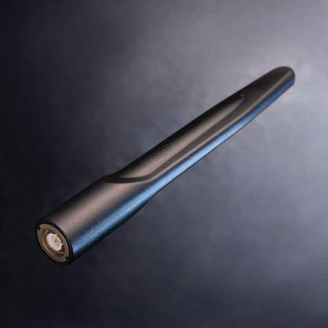
Antennas
With a military and industrial focus, we have solutions for radio tactical communications, vehicles, positioning, LMR/PMR and telemetry applications.

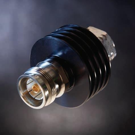
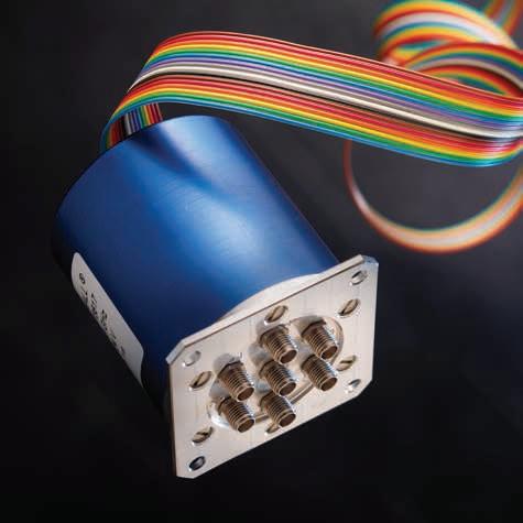
Outdoor Connectors
Designed for outdoor conditions, our range includes high-power RF coaxial connectors, linking antennas and radio units, as well as innovative multi-signal I/O solutions for optical, Ethernet, power or coaxial links between radio and network.
Microwave Components
Our range covers a wide frequency spectrum from DC to 50 GHz, and includes terminations, attenuators, couplers, power dividers, filters and other specialized components.
RF &
The patented design of our unique, modular actuator and transmission links guarantees operation up to 10 million cycles with superior repeatability.
Microwave Switches
COMPREHENSIVE
4 | INTRODUCTION
PORTFOLIO
At Radiall, we provide a comprehensive portfolio of products that meet the application requirements of the key industries we serve. By listening to our customers, we continuously develop new solutions and update our extensive range of products.
With over sixty years of experience and an understanding of the ever-changing business and our customers' technical requirements, we deliver the optimal and most cost-effective, end-to-end interconnect solutions available today.

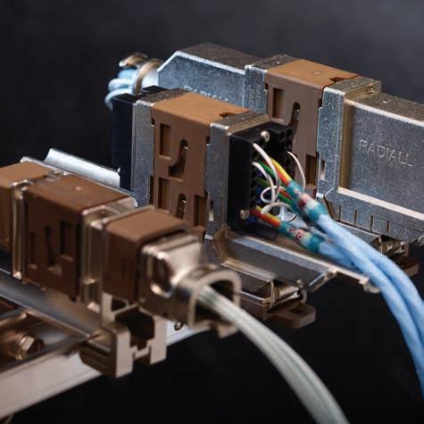
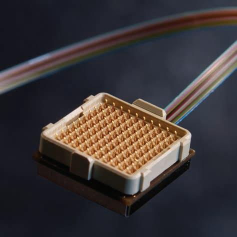
Multipin Aerospace Connectors
For more than 40 years, commercial airframes have trusted our range of rack and panel connectors and modular solutions. Our new miniature connector series combines high performance and reduced weight to meet civil and military aerospace industry demands.
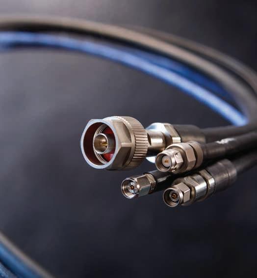
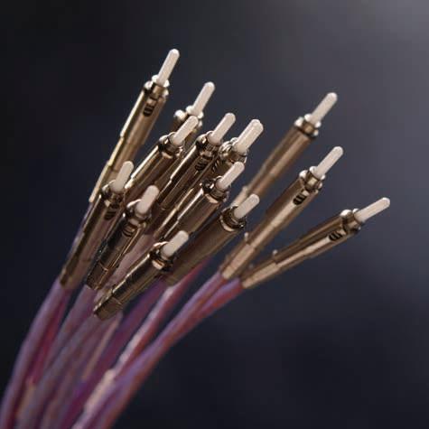
RF Cable Assemblies
Low-loss and high-frequency characterize our extensive range of cable assemblies, including flexible, semi-rigid and hand-formable solutions with a broad combination of cables and connectors.
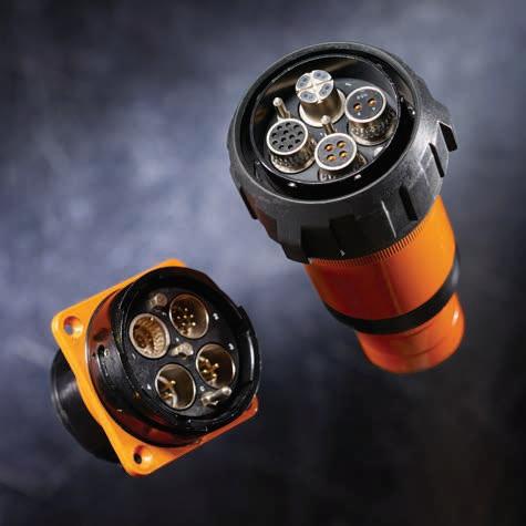
Multipin Industrial Connectors
Our Van-System brand designs and produces a range of robust circular electrical connectors suitable for harsh environments, such as railways, machine tools, and plant engineering equipment.
RF Coaxial Connectors
We offer the widest range of RF coaxial connectors in the industry; 55 product series are available, including AEP and Mil QPL connectors.
Optical Cable Assemblies
Our extensive product range and worldwide presence supports customers with standard configurations as well as optimized solutions based on customer requirements.
Space Qualified Components
Known for high quality as well as reliability and performance, our product offering includes a wide range of coaxial connectors, cable assemblies, microwave components and switches with a frequency range up to K a band.
INTRODUCTION | 5
NUMBERING SYSTEM
The following guide illustrates the AEP part numbering system for connectors. For additional information or AEP connector data sheets, visit us at www.radiall.com. Click on “Product Finder,” then “RF Coaxial Connectors” and select AEP.
AEP PART NUMBERS
Applied Engineering Products (AEP) was established in 1973 and quickly became a recognized leader in the RF coaxial connector and cable assembly industries. In 2005, Radiall, a well known world leader for reliable and innovative product solutions acquired Applied Engineering Products (AEP).
Since acquiring AEP, Radiall has maintained the initial customer-centric service established by AEP over 40 years ago and has become a center of excellence dedicated to providing design engineering, manufacturing, quality and supply chain functions to support worldwide demand.
Today, AEP is a Radiall product brand commercialized alongside the core Radiall RF product lines. AEP connectors and cable assemblies are designed and qualified by our dedicated staff. Radiall is well positioned to serve the needs of the Telecom, Industrial, Defense and Aerospace industries.
- SMC
- SMB
- SLB
- N
- Adapters
- TNC
- BNC
- SSMC 7200-7299 - SSMB 7300-7499 - SSLB
- Others
- SMA - SSMA
RG55, RG142, RG223
RG178, RG196
RG174, RG188, RG316
RD196, RD178
RG58, RG141
RG59, RG62
RD188, RD316, RD174
RG402
.085, RG405
RG401
MODEL NUMBER 1000-1999
2000-2999
3000-3999
4000-4999
5000-5999
6000-6499
7000-7199
9000-9999
PLATING 1 - Gold 6 - Silver 7 - Nickel 8 - Tin 9 - Passivated MATERIAL 1 - Brass 2 - Beryllium copper 3 - Stainless steel 4 - Brass & Stainless steel 6 - Ph bronze 7 - Brass
Ni CABLE GROUP 01 -
02
03
05
06
07
08 -
09
10 -
11 - .047 12 - .250,
25 - RD178 30 -
9006-9113-001 D C A A B B C D AEP NUMBER SYSTEM
6500-6999
8000-8999
over
-
-
-
-
-
- .141,
RG122
6 | INTRODUCTION

At Radiall, we share a common purpose –simplify life for all who innovate.

NOTES
Go online for data sheets and assembly instructions. Visit www.radiall.com/AEP and enter the part number.

SIMPLIFICATION IS OUR INNOVATON Visit www.radiall.com for more information. MIL-QPL SECTION 1
Simplification is Our Innovation. Go online for data sheets and assembly instructions. Visit www.radiall.com/AEP and enter the part number. 1-1 SMB 1-2
MIL-QPL
MIL-QPL
SMB
Straight plug for flexible cable Clamp type (Category A) Pg.
Gold-Plated Cable 3-6
M39012/67-0004 RG-316 -
Straight plug for flexible cable Crimp type (Category B) Pg.
Gold-Plated Cable 3-6
M39012/67B0009 RG-316M39012/67B0010 RG-179
Straight jack for flexible cable Clamp type (Category A) Pg.
Gold-Plated Cable 3-8
M39012/68-0004 RG-316 -
Straight jack for flexible cable Crimp type (Category B) Pg.
Gold-Plated Cable 3-8
M39012/68B0009 RG-316M39012/68B0010 RG-179
Bulkhead jack for flexible cable Clamp type (Category A)
Gold-Plated Cable 3-9
M39012/70-0004 RG-316 -
Rear mount bulkhead receptacle Solder pot contact Pg.
M39012/71-0001 -
Front mount bulkhead receptacle Solder pot contact Pg. Gold-Plated 3-10
M39012/71-0002 -
Straight P.C. board receptacle
M39012/95-0001 - 0.155 - M39012/95-0002 - 0.125 M39012/95-0003
Right angle plug for flexible cable Clamp type (Category A) Pg.
Gold-Plated Cable 3-8
M39012/69-0004 RG-316 -
012 /96-0002 -
012 /96-0003 M39012/96-0006
1-2
Go online for data sheets and assembly instructions. Visit www.radiall.com/AEP and enter the part number.
Pg.
receptacle Pg. Gold-Plated Silver-Plated Leg Length 3-12
0.155
Right angle P.C. board
M39 012 /96-0001 -
- M39
0.125 M39
0.093
Pg. Gold-Plated Silver-Plated Leg Length 3-12
M39012/95-0006 0.093
Gold-Plated 3-10
MIL-PRF-39012 P/N
M39012/55-3006 Discontinued 9201-9553-902 9201-9553-402
M39012/55-3007 Discontinued 9201-9553-903 9201-9553-503
M39012/55-3008 Discontinued 9201-9553-930 9201-9553-230
M39012/55-3009 Discontinued 9201-9553-901 9201-9553-401
M39012/55-3010 Discontinued 9201-9553-906 9201-9553-206
M39012/55-3025 Discontinued 9101-9573-902 9101-9573-402
M39012/55-3026 Discontinued 9101-9573-903 9101-9973-003
M39012/55-3027 Discontinued 9101-9573-930 9101-9573-230
M39012/55-3028 Discontinued 9101-9573-901 9101-9573-401
M39012/55-3029 Discontinued 9101-9573-906 9101-9573-206
M39012/55-3106 Discontinued 9201-9553-802 9201-9553-302
M39012/55-3107 Discontinued 9201-9553-803 9201-9553-403
M39012/55-3108 Discontinued 9201-9553-830 9201-9553-130
M39012/55-3109 Discontinued 9201-9553-801 9201-9553-301
M39012/55-3110 Discontinued 9201-9553-806 9201-9553-106
M39012/55-3125 Discontinued 9101-9573-802 9101-9573-302
M39012/55-3126 Discontinued 9101-9573-803 9101-9873-003
M39012/55-3127 Discontinued 9101-9573-830 9101-9573-130
M39012/55-3128 Discontinued 9101-9573-801 9101-9573-301
M39012/55-3129 Discontinued 9101-9573-806 9101-9573-106
M39012/59-3006 Discontinued 9230-9553-902 9230-9553-602
M39012/59-3007 Discontinued 9230-9553-903 9230-9553-103
M39012/59-3008 Discontinued 9230-9553-930 9230-9553-130
M39012/59-3009 Discontinued 9230-9553-901 9230-9553-101
M39012/59-3010 Discontinued 9230-9553-906 9230-9553-106
M39012/60-3001 Discontinued 9404-9113-999 9404-9113-009
M39012/60-3002 Discontinued 9408-9113-999 9408-9113-007
M39012/61-3001 Discontinued 9432-9113-999 9432-9113-001
M39012/61-3002 Discontinued 9465-9113-999 9465-9113-001
M39012/67-0003 Discontinued 2002-1551-902 2002-1551-202
M39012/67-0004 Active 2002-1551-903 N/A
M39012/67-0103 Discontinued 2002-6551-902 2002-6551-202
M39012/67-0104 Discontinued 2002-6551-903 2002-6551-603
M39012/67B0008 Discontinued 2002-1571-902 2002-1571-302
M39012/67B0009 Active 2002-1571-903 N/A
*Only applies where status is “Discontinued”; the AEP part is no longer active.
1-3
Simplification
Go online for data sheets and assembly instructions. Visit www.radiall.com/AEP and enter the part number.
MIL-QPL
is Our Innovation.
AEP MIL-QPL
AEP Old* MIL-QPL
AEP
Status
P/N
Commercial Equivalent P/N
MIL-QPL
MIL-PRF-39012
M39012/67B0010 Active 2002-1571-803 N/A
M39012/67B0013 Discontinued 2002-6571-902 2002-6571-302
M39012/67B0014 Discontinued 2002-6571-903 2002-6571-703
M39012/67B0015 Discontinued 2002-6571-803 2002-6571-603
M39012/68-0003 Discontinued 2001-1551-902 2001-1551-102
M39012/68-0004 Active 2001-1551-903 N/A
M39012/68-0103 Discontinued 2001-6551-902 2001-6551-102
M39012/68-0104 Discontinued 2001-6551-903 2001-6551-203
M39012/68B0008 Discontinued
M39012/68B0009 Active 2001-1571-903 N/A
M39012/68B0010 Active 2001-1571-803 N/A
M39012/68B0013 Discontinued
M39012/68B0014 Discontinued 2001-6571-903 2001-6571-603
M39012/68B0015 Discontinued 2001-6571-803 2001-6571-403
M39012/69-0003 Discontinued 2005-1551-902
M39012/69-0004 Active 2005-1551-903 N/A
M39012/69-0012 Discontinued 2105-1921-803 2105-1001-803
M39012/69-0017 Discontinued 2105-6921-903 2105-1001-903
M39012/69-0103 Discontinued 2005-6551-902 2005-6551-202
M39012/69-0104 Discontinued 2005-6551-903 2005-6551-403
M39012/69B0008 Discontinued 2105-1521-902 2105-1921-102
M39012/69B0009 Discontinued 2105-1521-903 2105-1921-503
M39012/69B0010 Discontinued 2105-1521-803 2105-1921-603
M39012/69B0013 Discontinued 2105-6521-902 2105-6921-102
M39012/69B0014 Discontinued 2105-6521-903 2105-6921-503
M39012/69B0015 Discontinued 2105-6521-803 2105-6921-603
M39012/70-0003 Discontinued 2003-1551-902 2003-1551-302
M39012/70-0004 Active 2003-1551-903 N/A
M39012/70-0103 Discontinued 2003-6551-902 2003-6551-302
M39012/70-0104 Discontinued 2003-6551-903 2003-6551-603
M39012/70B0008 Discontinued 2003-1571-902 2003-1571-502
M39012/70B0009 Discontinued 2003-1571-903 2003-1571-603
M39012/70B0010 Discontinued 2003-1571-803 2003-1571-403
M39012/70B0013 Discontinued 2003-6571-902 2003-6571-502
M39012/70B0014 Discontinued 2003-6571-903 2003-6571-603
*Only applies where status is “Discontinued”; the AEP part is no longer active.
1-4
Go online for data sheets and assembly instructions. Visit www.radiall.com/AEP and enter the part number.
Old* MIL-QPL
P/N AEP MIL-QPL Status AEP
P/N AEP Commercial Equivalent P/N
2001-1571-902 2001-1571-202
2001-6571-902 2001-6571-202
2005-1551-202
MIL-PRF-39012 P/N
M39012/70B0015 Discontinued 2003-6571-803 2003-6571-403
M39012/71-0001 Active 2004-1511-999 N/A
M39012/71-0002 Active 2019-1511-999 N/A
M39012/71-0003 Discontinued 2004-6511-999 2004-6511-012
M39012/71-0004 Discontinued 2019-6511-999 2019-6511-025
M39012/73-0003 Discontinued 1002-1551-902
1002-1551-202
M39012/73-0004 Discontinued 1002-1551-903 1002-1851-003
M39012/73-0103 Discontinued 1002-6551-902 1002-6551-202
M39012/73-0104 Discontinued 1002-6551-903 1002-6851-003
M39012/73B0008 Discontinued
1002-1571-902
1002-1571-102
M39012/73B0009 Discontinued 1002-1571-903 1002-1571-603
M39012/73B0010 Discontinued
M39012/73B0013 Discontinued
M39012/73B0014 Discontinued
M39012/73B0015 Discontinued
M39012/74-0003 Discontinued
M39012/74-0004 Discontinued
M39012/74-0103 Discontinued
M39012/74-0104 Discontinued
M39012/74B0008 Discontinued
M39012/74B0009 Discontinued
M39012/74B0010 Discontinued
M39012/74B0014 Discontinued
M39012/74B0015 Discontinued
M39012/74B0016 Discontinued
M39012/75-0003 Discontinued
M39012/75-0004 Discontinued
M39012/75-0103 Discontinued
M39012/75-0104 Discontinued
M39012/75B0008 Discontinued
M39012/75B0009 Discontinued
M39012/75B0010 Discontinued
M39012/75B0014 Discontinued
M39012/75B0015 Discontinued
M39012/75B0016 Discontinued
1002-1571-803
1002-6571-902
1002-6571-903
1002-6571-803
1001-1551-902
1001-1551-903
1001-6551-902
1001-6551-903
1001-1571-902
1001-1571-903
1001-1571-803
1001-6571-902
1001-6571-903
1001-6571-803
1005-1551-902
1005-1551-903
1005-6551-902
1005-6551-903
1105-1521-902
1105-1521-903
1105-1521-803
1105-6521-902
1105-6521-903
1105-6521-803
1002-1571-503
1002-6571-102
1002-6571-603
1002-6571-503
1001-1551-102
1001-1551-303
1001-6551-102
1001-6551-303
1001-1571-102
1001-1571-203
1001-1571-103
1001-6571-102
1001-6571-203
1001-6571-103
1005-1551-202
1005-1551-303
1005-6551-202
1005-6551-303
1105-1521-402
1105-1821-003
1105-1521-703
1105-6521-402
1105-6821-003
1105-6521-703
*Only applies where status is “Discontinued”; the AEP part is no longer active.
1-5
Simplification
Go online for data sheets and assembly instructions. Visit www.radiall.com/AEP and enter the part number.
MIL-QPL
is Our Innovation.
AEP MIL-QPL
AEP Old* MIL-QPL
AEP Commercial
Status
P/N
Equivalent P/N
MIL-QPL
M39012/76-0003 Discontinued
M39012/76-0004 Discontinued
M39012/76-0103 Discontinued
1003-1551-902
1003-1551-903
1003-6551-902
M39012/76-0104 Discontinued 1003-6551-903
M39012/76B0008 Discontinued 1003-1571-902
M39012/76B0009 Discontinued 1003-1571-903
M39012/76B0010 Discontinued 1003-1571-803
M39012/76B0014 Discontinued 1003-6571-902
M39012/76B0015 Discontinued
M39012/76B0016 Discontinued
1003-6571-903
1003-6571-803
1003-1551-102
1003-1551-203
1003-6551-102
1003-6551-203
1003-1571-102
1003-1571-303
1003-1571-203
1003-6571-102
1003-6571-303
1003-6571-203
M39012/77-0001 Discontinued 1004-1511-999 1004-1511-011
M39012/77-0002 Discontinued 1019-1511-999 1019-1511-017
M39012/77-0003 Discontinued 1004-6511-999 1004-6511-011
M39012/77-0004 Discontinued 1019-6511-999 1019-6511-017
M39012/79B3003 Discontinued 9501-9593-910 9501-9593-210
M39012/79B3004 Discontinued 9501-9593-909 9501-9593-509
M39012/79B3103 Discontinued 9501-9593-810 9501-9593-110
M39012/79B3104 Discontinued 9501-9593-809 9501-9593-409
M39012/83B3003 Discontinued 9530-9593-910 9530-9593-210
M39012/83B3004 Discontinued 9530-9593-909 9530-9593-209
M39012/92B3001 Discontinued 9301-1063-909 9301-1863-009
M39012/92B3101 Discontinued 9301-1003-909 9301-1803-009
M39012/95-0001 Active 2009-1511-999 N/A
M39012/95-0002 Active 2009-1511-899 N/A
M39012/95-0003 Active 2009-1511-799 N/A
M39012/95-0004 Discontinued 2009-6511-999 2009-6511-048
M39012/95-0005 Discontinued 2009-6511-899 2009-6511-052
M39012/95-0006 Active 2009-6511-799 N/A
M39012/96-0001 Active 2010-1511-999 N/A
M39012/96-0002 Active 2010-1511-899 N/A
M39012/96-0003 Active 2010-1511-799 N/A
M39012/96-0004 Discontinued 2010-6511-999 2010-6511-032
M39012/96-0005 Discontinued 2010-6511-899 2010-6511-031
M39012/96-0006 Active 2010-6511-799 N/A
*Only applies where status is “Discontinued”; the AEP part is no longer active.
1-6
Go online for data sheets and assembly instructions. Visit www.radiall.com/AEP and enter the part number.
AEP MIL-QPL
AEP Old* MIL-QPL
AEP Commercial Equivalent P/N
MIL-PRF-39012 P/N
Status
P/N
SIMPLIFICATION IS OUR INNOVATON Visit www.radiall.com for more information. SECTION 2 SMA
2-1 Simplification is Our Innovation. Go online for data sheets and assembly instructions. Visit www.radiall.com/AEP and enter the part number. Specifications 2-3 Cable Attachment Methods 2-4 Semi-rigid Connectors 2-8 Flexible Cable Connectors 2-14 Panel (Flange Mount) Receptacles 2-19 Bulkhead Receptacles 2-28 Knurl Mount 2-30 P.C. Board Receptacles 2-31 Stripline Receptacles 2-32 Hermetic Seal Launchers 2-33 Adapters Within Series 2-52 SECTION 2 TABLE OF CONTENTS
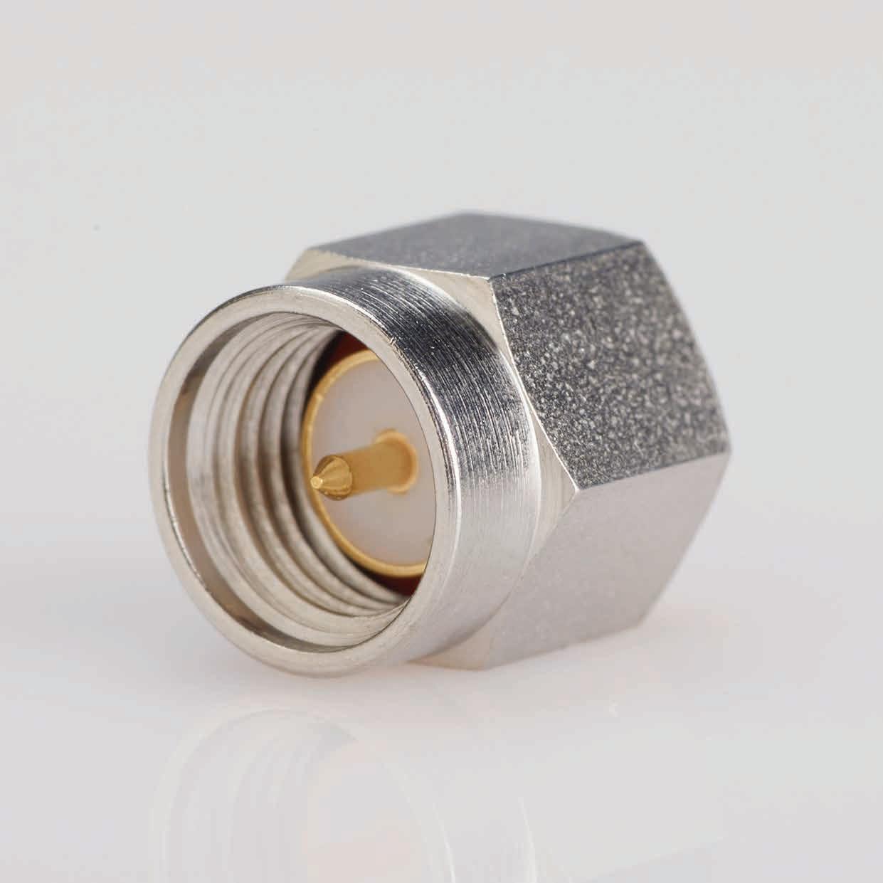
SMA
All AEP SMA series connectors meet or exceed MIL-PRF-39012 requirements, offering good electrical performance to 18 GHz. Our unique method of captivating contacts and insulators greatly reduces RF leakage by eliminating epoxy fill holes in the connector body (see page 2-7 for details).
Most of the items shown are available with either gold-plated bodies or a less expensive finish (nickelplating or passivated finish); part numbers for each finish are shown in the product section. The coupling nuts of the plug connectors are passivated in all cases.
Pages 2-4 through 2-6 show the various options for cable attachment types. Standard cables for use with AEP SMA connectors are shown at the bottom of the appropriate product pages. If you require an SMA for use with a cable type other than those shown, please contact your local representative. A complete listing of cable groups is on page 13-6.
The index listing for each connector shows the appropriate assembly instruction number and trim code; assembly instructions start on page 13-7.
Please contact us directly for custom solutions as we have made hundreds of variations of the items shown here and can likely supply a solution for special connector requirements.
Factory-built cable assemblies using these connectors are available from AEP.
2-2
Go online for data sheets and assembly instructions. Visit www.radiall.com/AEP and enter the part number.
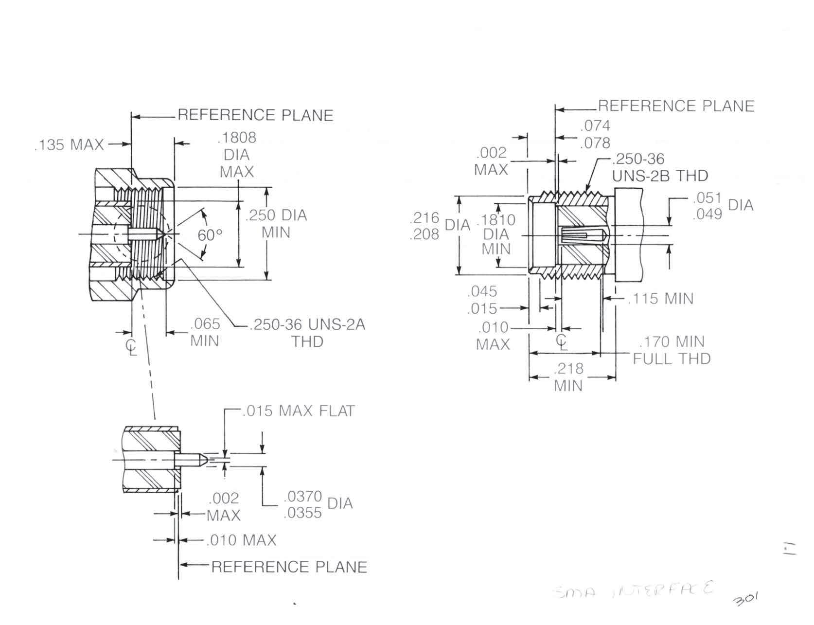
INTERFACE DIMENSIONS
PER MIL-STD-348
SPECIFICATIONS
MIL-PRF-39012
MATERIALS:
Body parts: Stainless steel per ASTM-A-582, type 303
Contacts: Beryllium copper per ASTM B196, condition HT
Insulators: Teflon TFE per ASTM-D-1710
Gaskets: Silicone rubber per ZZ-R-765, class 2B, grade 65-75
FINISH:
Center contacts: Gold-plate per MIL-G-45204
All other parts are finished to meet MIL-PRF-39012 corrosion requirements.
ELECTRICAL:
Insulation resistance: Greater than 5,000 MΩ
Dielectric withstanding voltage: Per MIL-STD-202, method 301
RF highpot voltage:
335-675 VAC at 5-7.5 MHz, dependent on cable type
Contact resistance: 3 mΩ max
RF leakage: -60 dB min, 2-3 GHz
Insertion loss: 0.03×√f (GHz) max test frequency 6 GHz
VSWR (straight cable plugs and jacks):
RG178: 1.20+[0.025×f (GHz)], DC-12.4 GHz
RG316: 1.15+[0.020×f (GHz)], DC-12.4 GHz
RG142: 1.15+[0.010×f (GHz)], DC-12.4 GHz
RG402 (non-captive contact): 1.05+[0.008×f (GHz)], DC-18 GHz
RG402 (captive contact): 1.05+[0.001×f (GHz)], DC-18 GHz
RG405 (captive contact): 1.07+[0.010×f (GHz)], DC-18 GHz
RG405 (non-captive contact): 1.07+[0.008×f (GHz)], DC-18 GHz
VSWR SPECIFICATIONS ARE NOT APPLICABLE TO NON-CABLED CONNECTORS.
Impedance: 50 Ω
Frequency range: DC to 8, 12.4 or 18 GHz, dependent on cable type and configuration
MECHANICAL:
Engage/disengage force: 2 lb max
Mating characteristics: Dimensions per above
For female contacts (after 5 insertions of 0.0375 Ø pin, 0.040 min depth):
Insertion force with 0.037 min Ø pin, 2 lb max
Withdrawal force for 0.0355 max Ø pin, 1 oz min
Contact retention (captive contact connectors): 6 lb min axial force
Durability: 500 mating cycles
ENVIRONMENTAL: (per MIL-STD-202)
Vibration: Method 204, test condition D
Mechanical shock: Method 213, condition I
Thermal shock: Method 107, condition B
Corrosion: Method 101, condition B, 5% salt solution
Moisture resistance: Method 106
Corona level: Corona free at 70,000 ft
Voltage dependent on cable size
Temperature rating: -65°C to + 165°C
2-3 SMA Simplification is Our Innovation. Go online for data sheets and assembly instructions. Visit www.radiall.com/AEP and enter the part number.
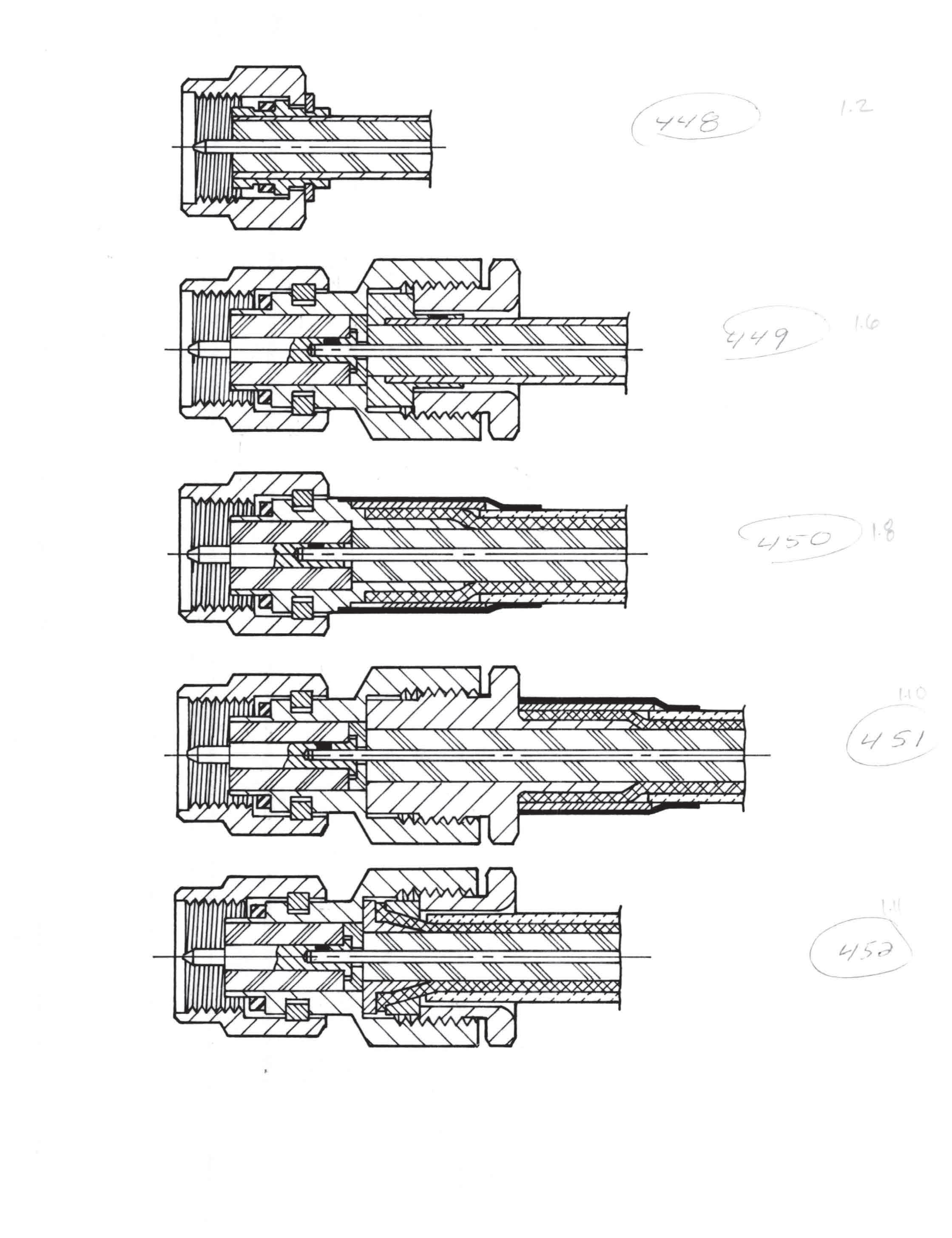
CABLE ATTACHMENT METHODS
2-4
Go online for data sheets and assembly instructions.
SMA
Direct Solder for Semi-Rigid Cable
Solder-Clamp for Semi-Rigid Cable
This attachment method is the most useful for right angle plugs and all bulkhead jacks. After the connector is assembled to the cable, it can be repositioned relative to the cable by loosening the clamp nut. When the proper orientation is reached, it can be held in the correct position by retightening the nut. The electrical performance is similar to direct-solder plugs with contacts.
Direct Solder with Captive Contact for Semi-Rigid Cable
These connectors have electrical performance similar to types with non-captive contacts, but assembly is much easier. The cable is simply stripped and inserted into the connector until it stops, and the jacket soldered to the body. The proper contact gap is automatically held and no contact soldering is required.
2-5 SMA Simplification is Our Innovation. Go online for data sheets and assembly instructions. Visit www.radiall.com/AEP and enter the part number.
Crimp Type for Flexible Cable (Non-captive Contact)
Crimp Type for Flexible Cable (Captive Contact)
This attachment method mechanically captivates the center contact to eliminate movement during cable flexure or thermal stress.
Clamp Type for Flexible Cable (Captive Contact)
These connectors can be assembled without special tooling and are field replaceable.
2-6 Go online for data sheets and assembly instructions. Visit www.radiall.com/AEP and enter the part number.
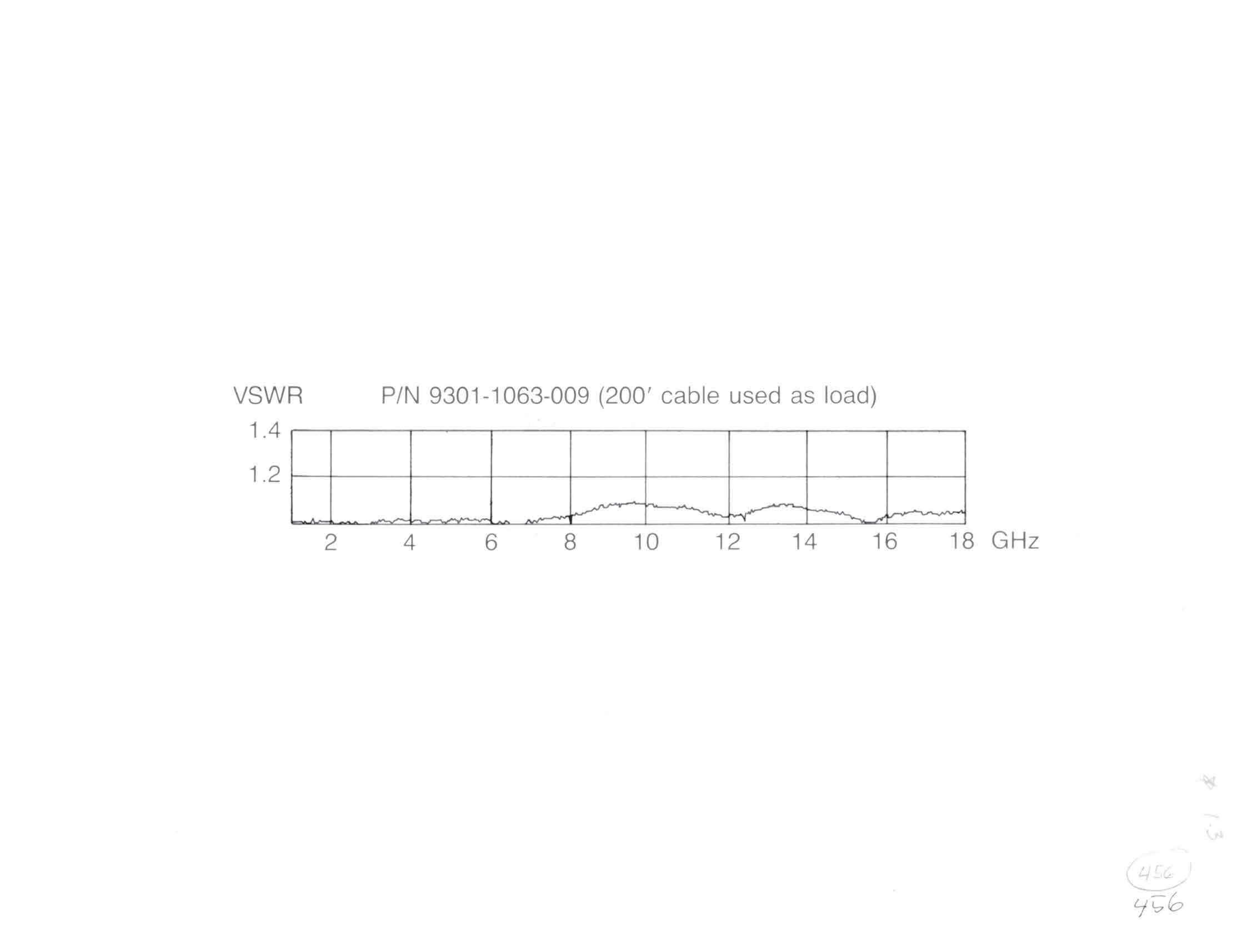
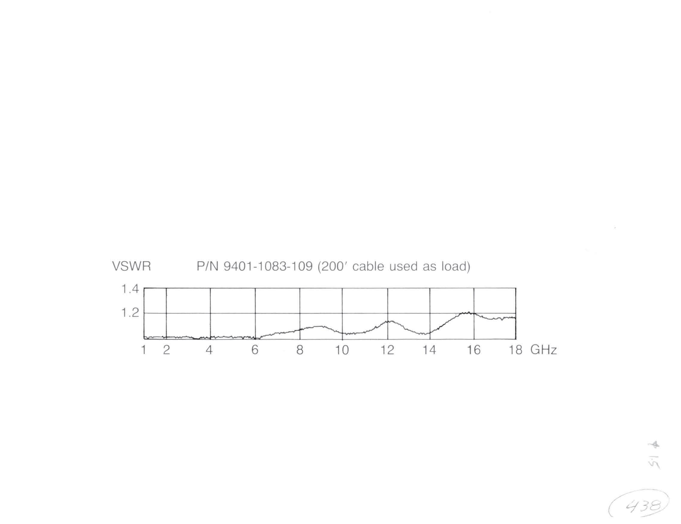
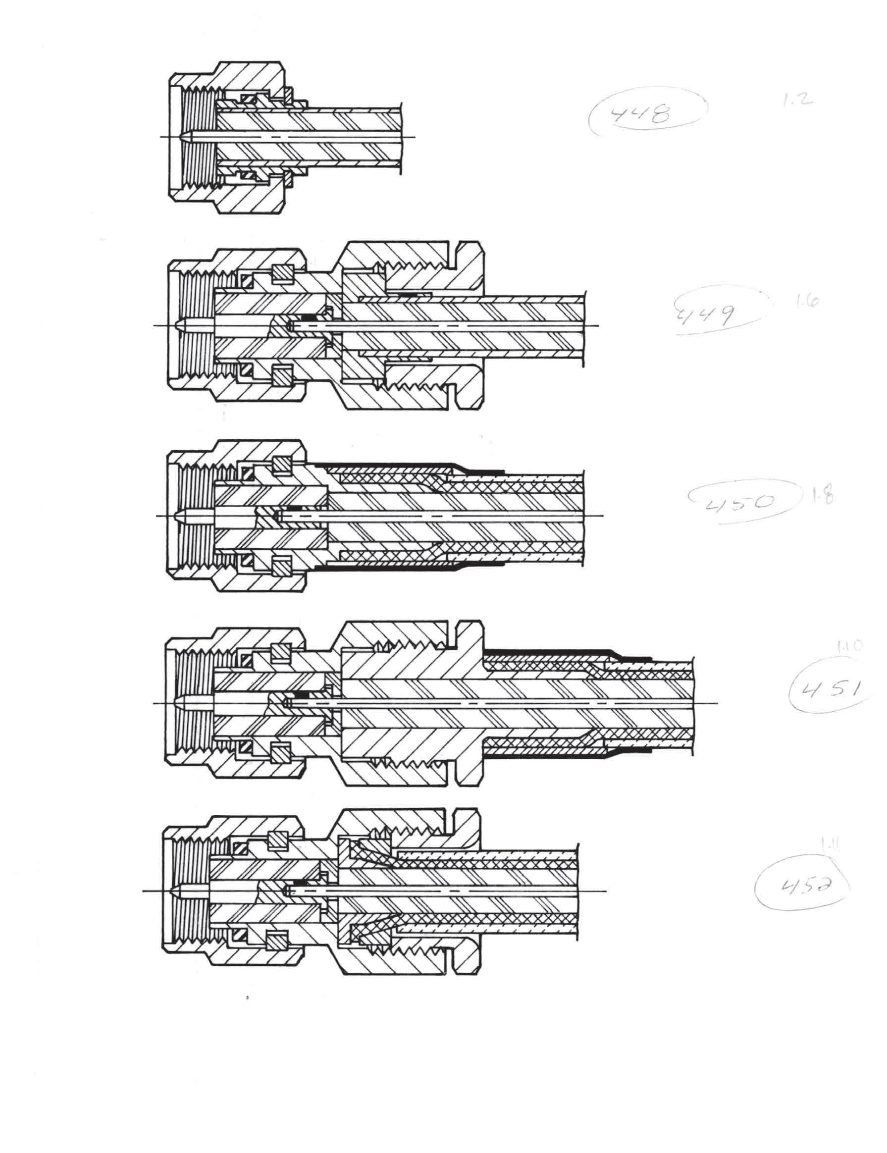
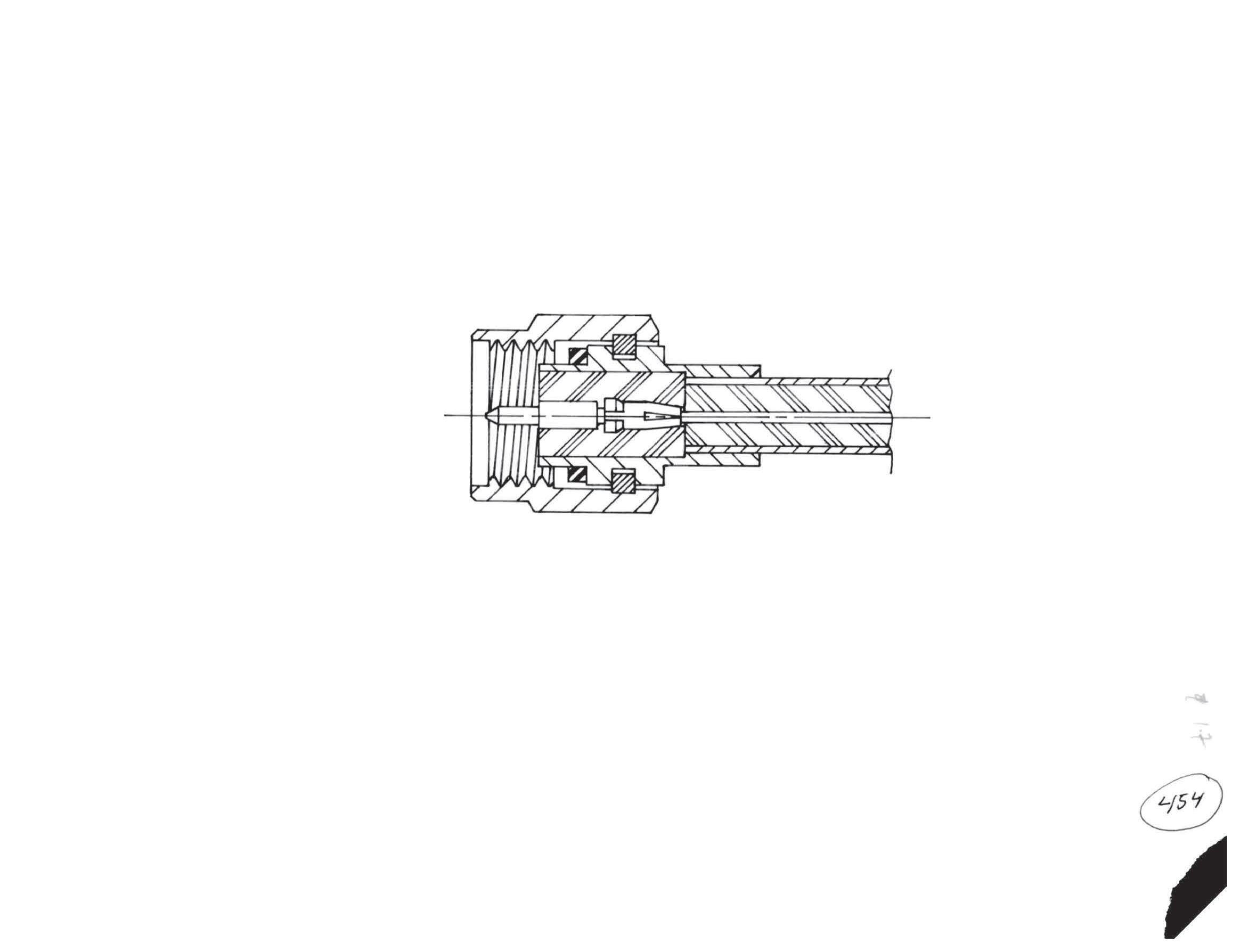
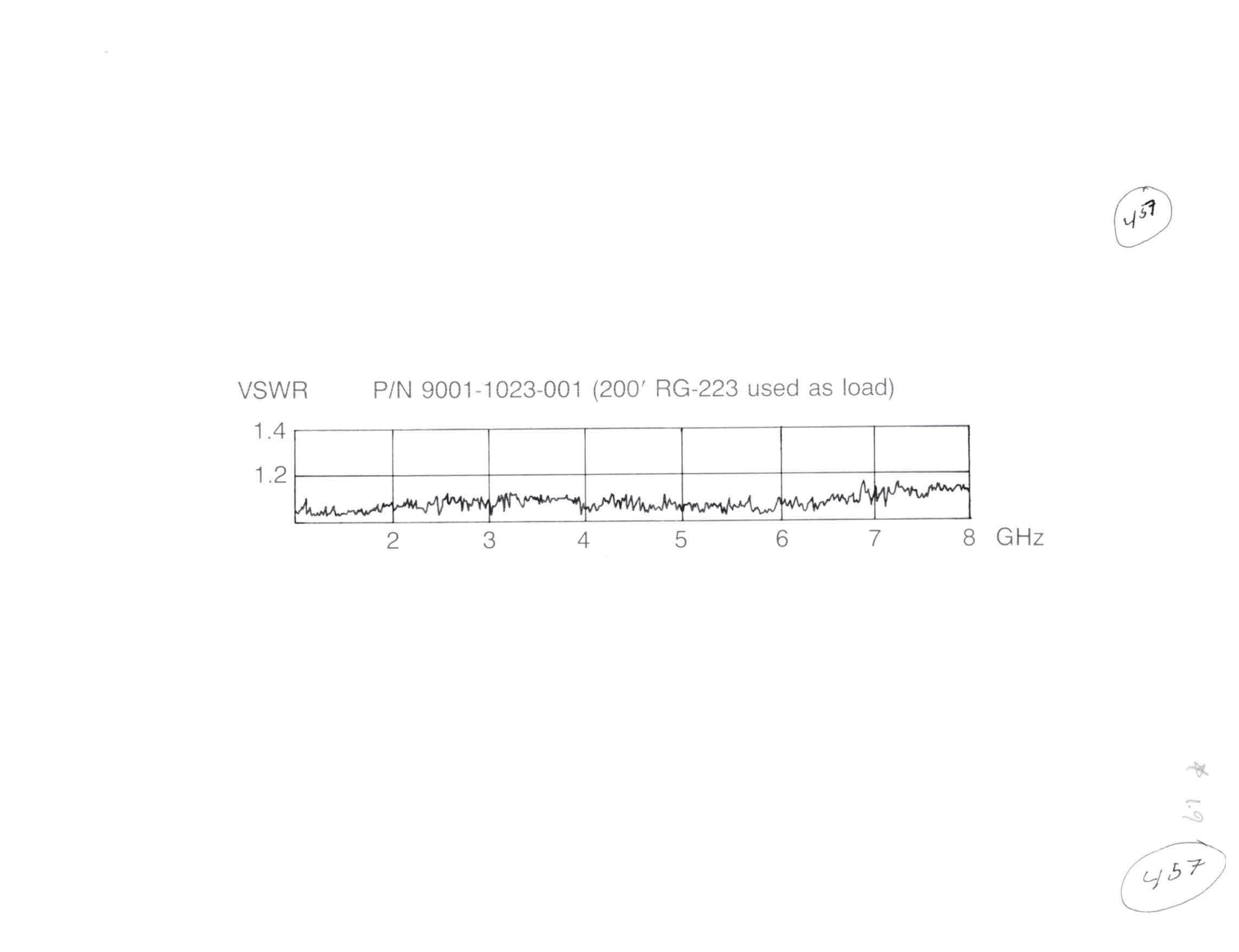
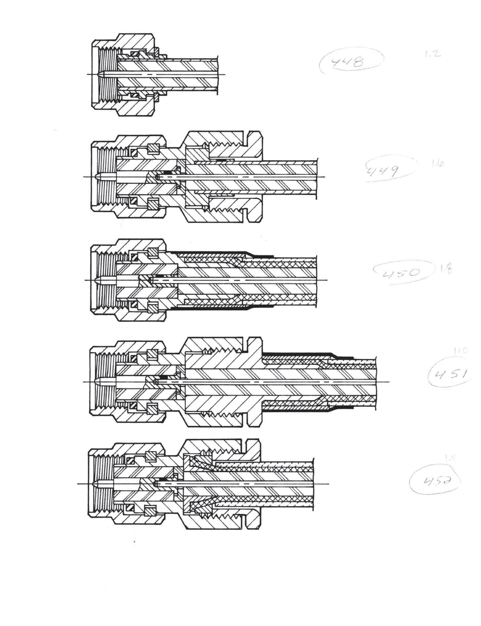
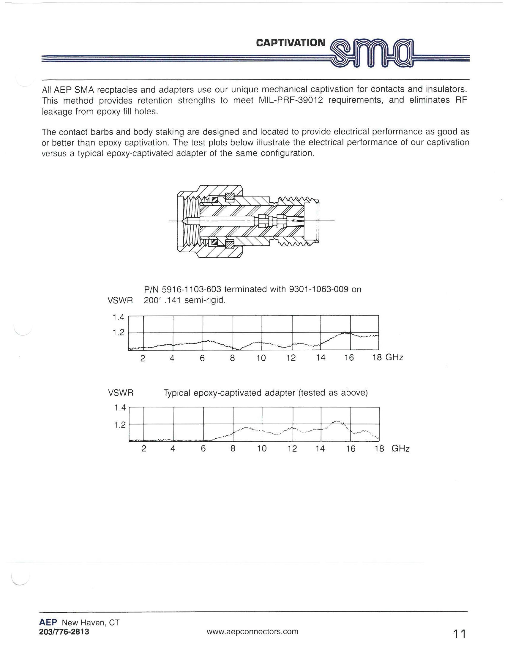
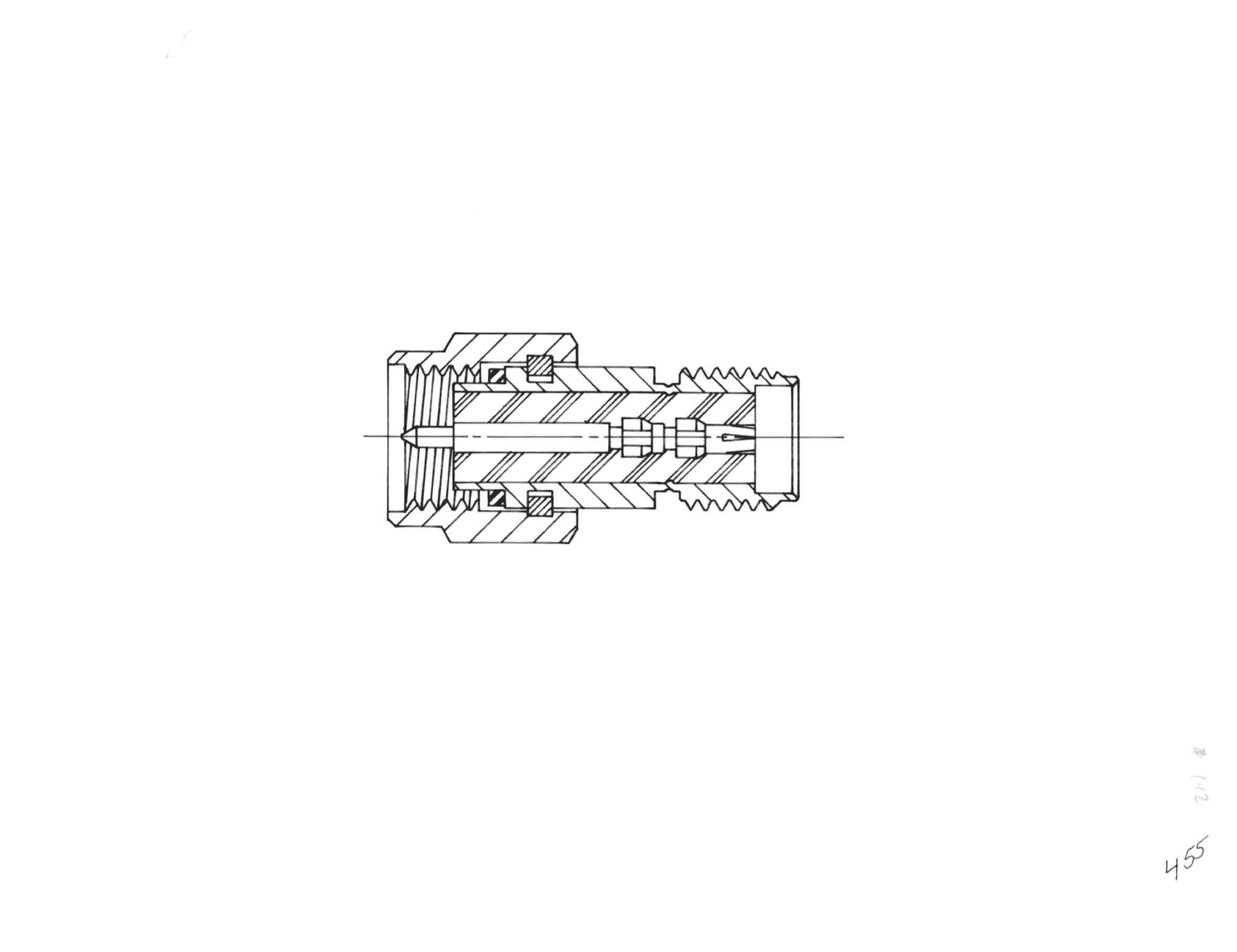
All AEP SMA receptacles and adapters use our unique mechanical captivation for contacts and insulators. This method provides retention strengths to meet MIL-PRF-39012 requirements, and eliminates RF leakage from epoxy fill holes. The contact barbs and body staking are designed and located to provide electrical performance as good as, or better than, epoxy captivation. The test plots below illustrate the electrical performance of our captivation versus a typical epoxy-captivated adapter of the same configuration.
2-7
Go online for data sheets and assembly instructions. Visit www.radiall.com/AEP and enter the part number.
SMA Simplification is Our Innovation.
SMA
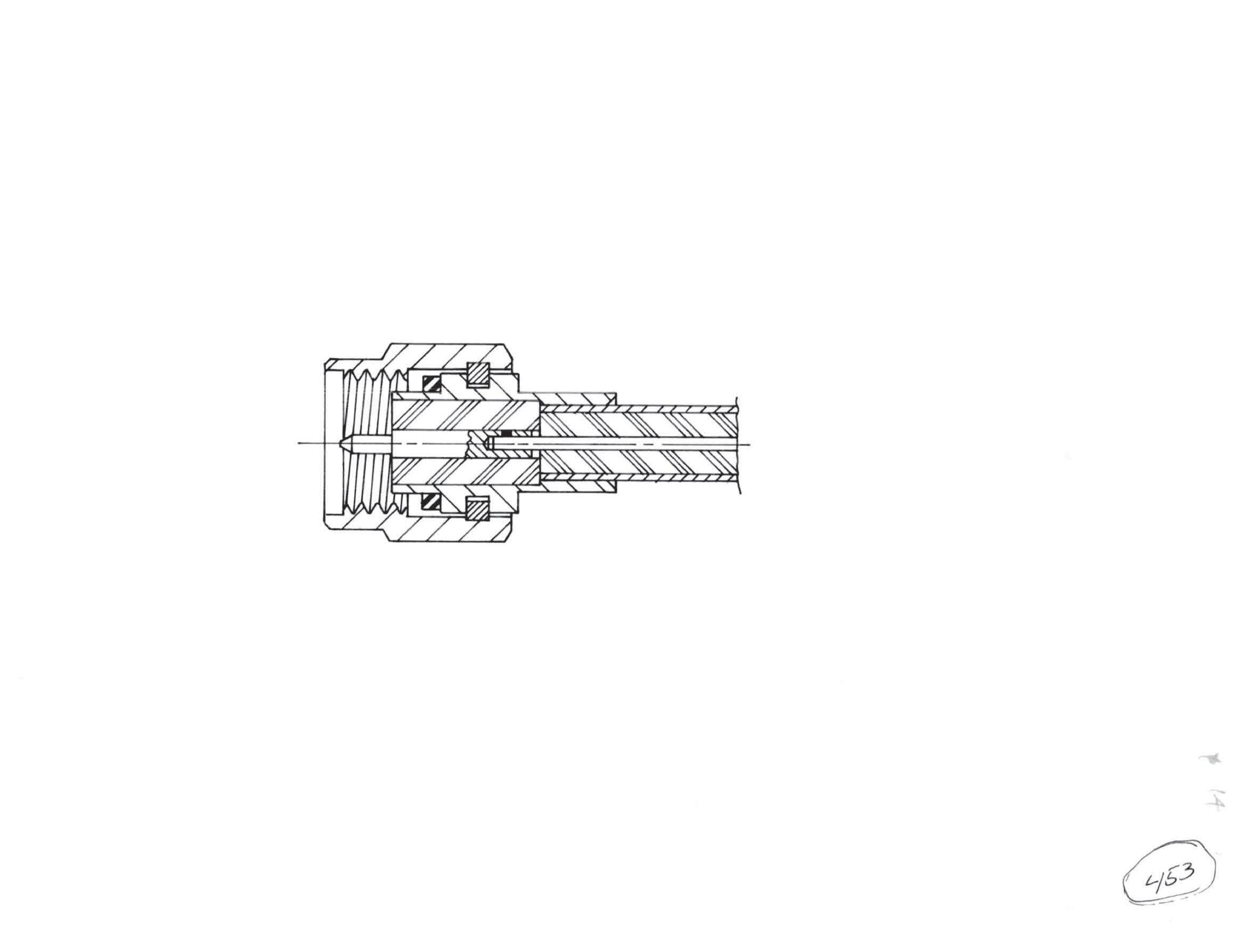
Semi-Rigid Cable Plugs
Straight Plug
• Direct solder attachment
• Retractable coupling nut
• Cable center conductor used as contact
For 0.141˝ semi-rigid: 9301-1063-009 (Gold-plated) 9301-7063-009 (Nickel-plated)
Straight Plug
• Direct solder attachment
• Retractable coupling nut
• Cable center conductor used as contact
• Stepped body for use in applications requiring frequent mating and unmating
For 0.141˝ semi rigid: 9301-1063-109 (gold-plated) 9301-7063-109 (nickel-plated)
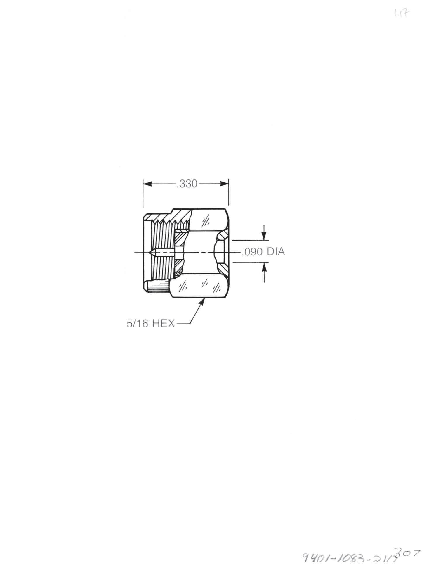
Straight Plug
• Direct solder attachment
• Provided with contact and insulator
• Non-captive contact
• Short body length allows very tight cable bend in dense packaging applications
For 0.085˝ semi-rigid: 9401-1083-210 (Gold-plated) 9401-7083-210 (Nickel-plated)
Visit www.radiall.com/AEP and enter the part number.
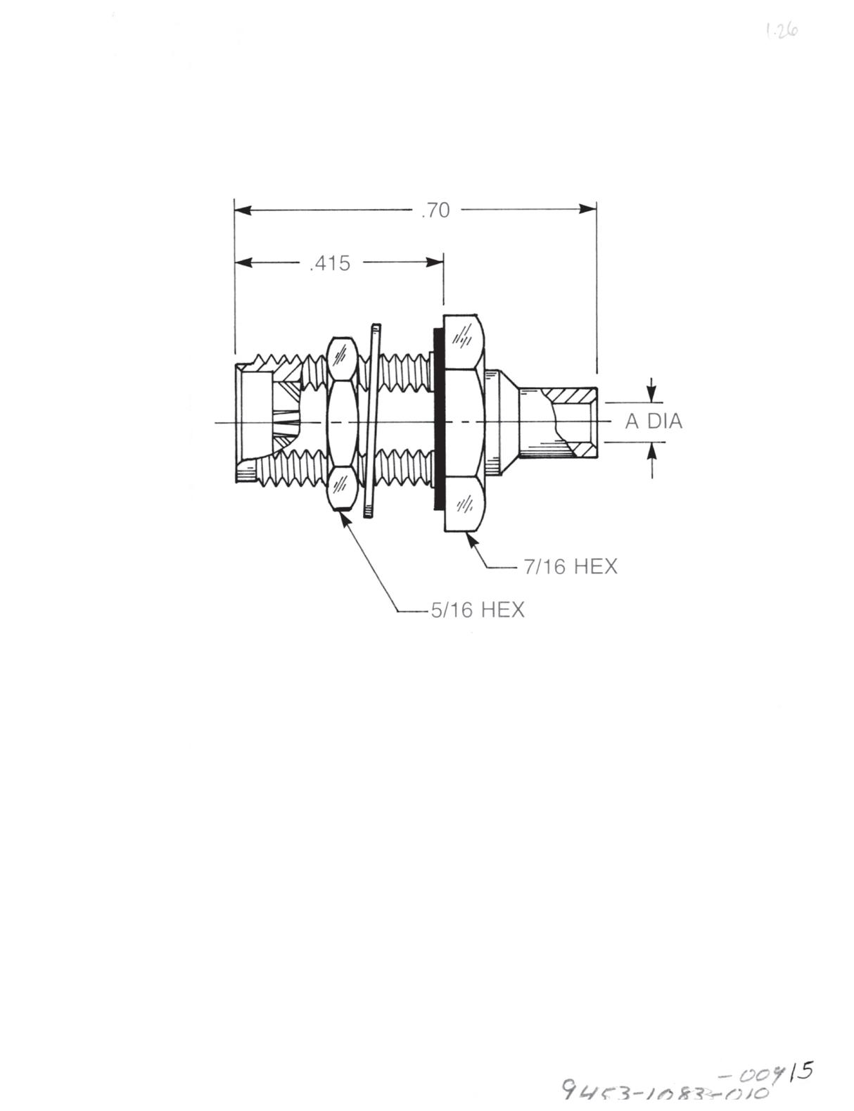
Semi-Rigid Cable Plugs
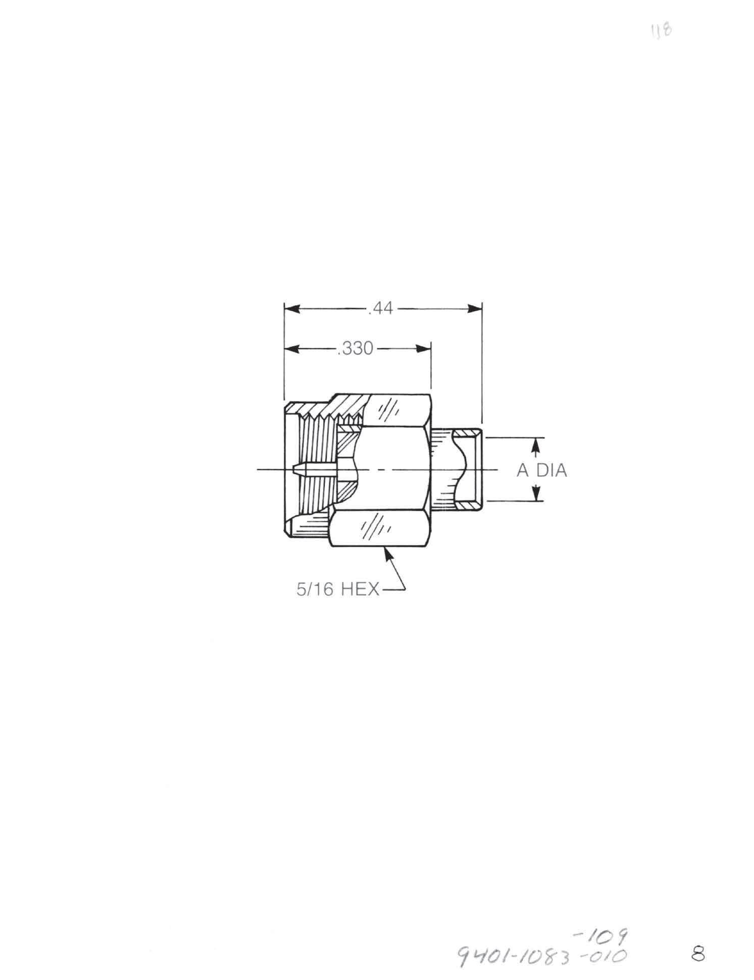
Straight Plug
• Direct solder attachment
• Provided with contact and insulator
• Non-captive contact
For 0.085˝ semi-rigid (A = 0.089): 9401-1083-010 (Gold-plated) 9401-7083-010 (Nickel-plated)
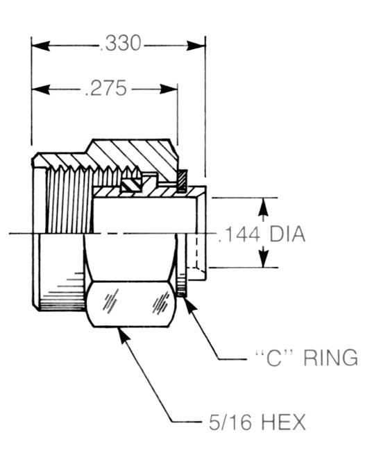
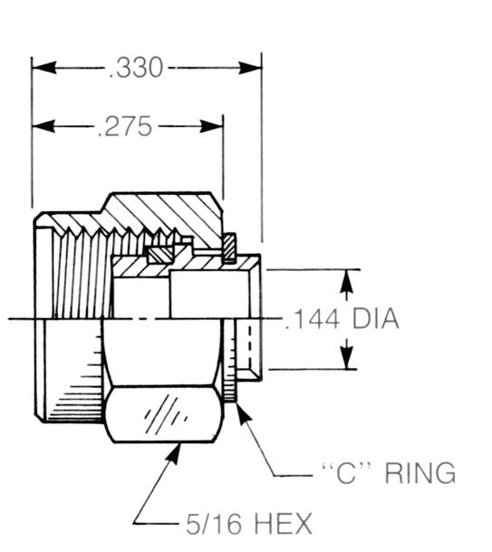
For 0.141˝ semi-rigid (A = 0.144): 9401-1083-109 (Gold-plated) 9401-7083-109 (Nickel-plated)
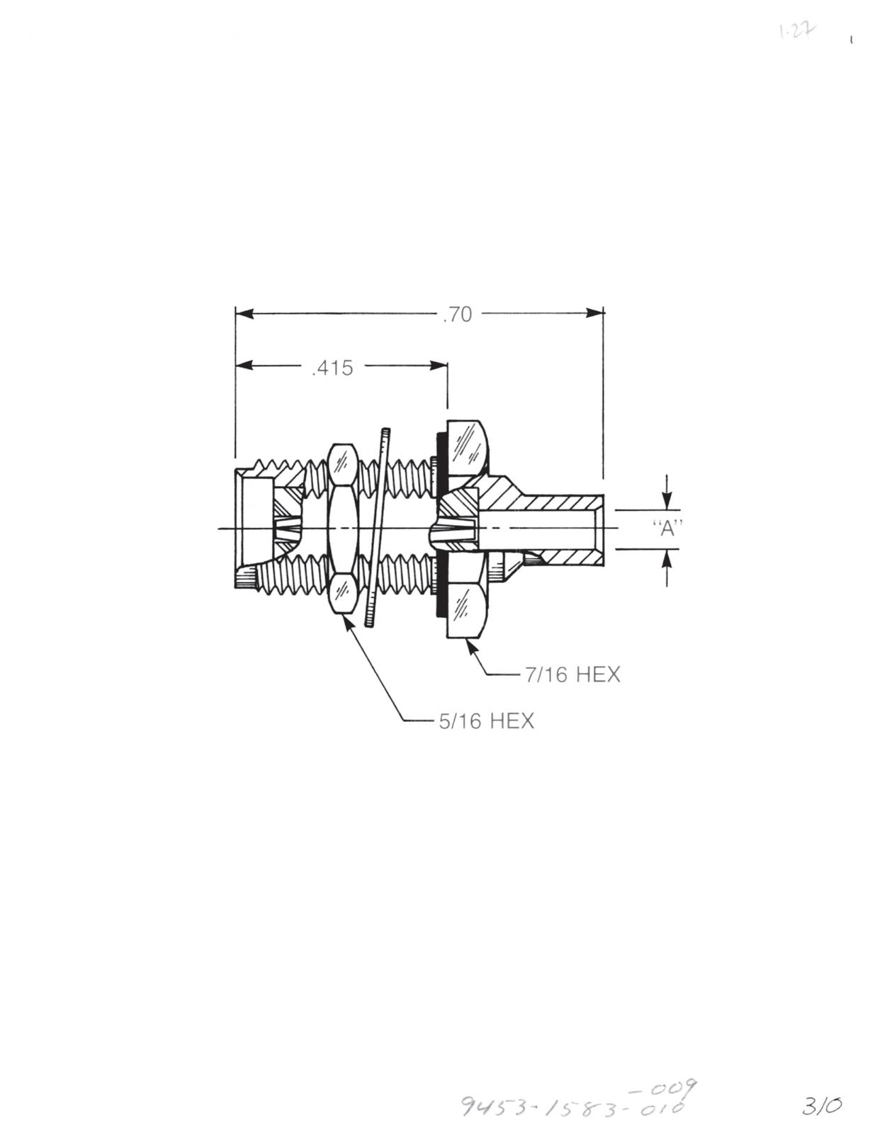
Straight Plug
• Direct solder attachment
• Provided with contact and insulator
• Captive contact for one-step cable assembly
For 0.085˝ semi-rigid (A = 0.089): 9401-1583 -010 (Gold-plated) 9401-7583-010 (Nickel-plated)
For 0.141˝ semi-rigid (A = 0.144): 9401-1583-109 (Gold-plated) 9401-7583-109 (Nickel-plated)
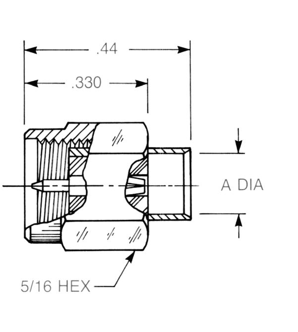
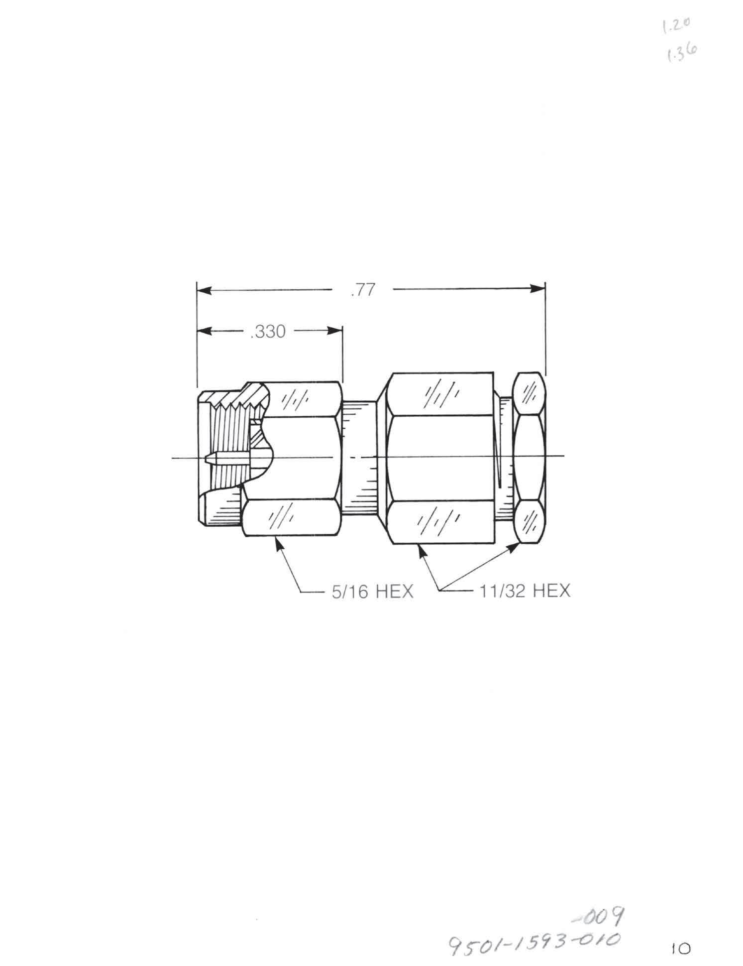
Straight Plug
• Solder-clamp attachment
• Captive contact
For 0.085˝ semi-rigid: 9501-1593-010 (Gold-plated) 9501-9593-010 (Passivated)
For 0.141˝ semi-rigid: 9501-1593-009 (Gold-plated) 9501-9593-009 (Passivated)
2-9
Simplification is Our Innovation. Visit www.radiall.com/AEP and enter the part number.
SMA
Semi-Rigid Cable Plugs
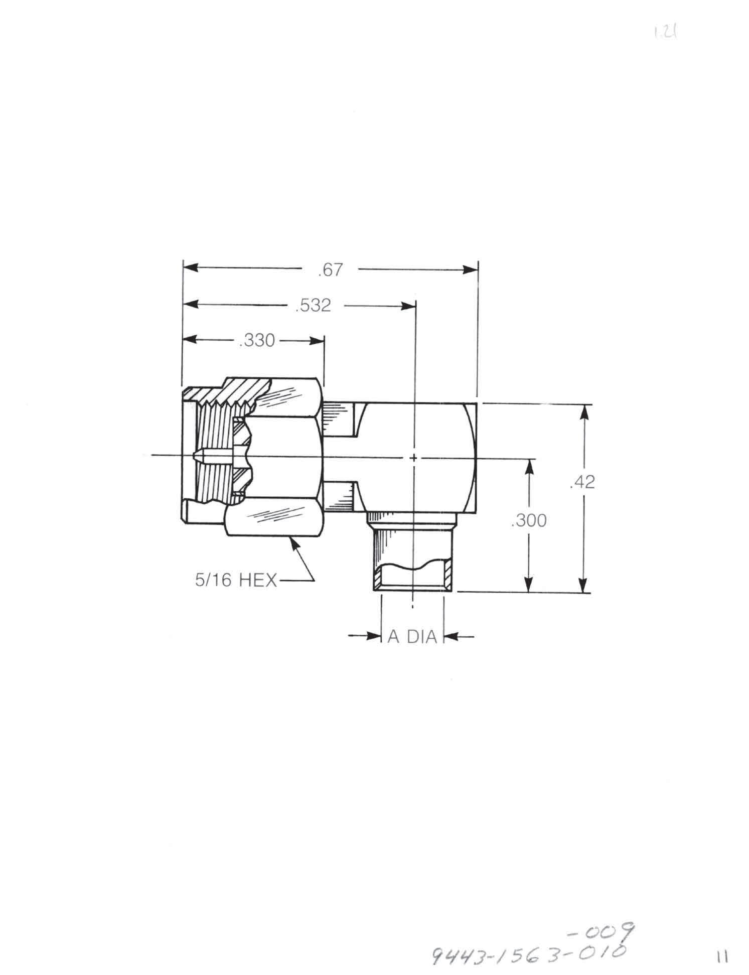
Right Angle Plug Direct solder attachment
For 0.085˝ semi-rigid (A = 0.089):
9443-1563-010 (Gold-plated)
9443-7563-010 (Nickel-plated)
For 0.141˝ semi-rigid (A = 0.144):
9443-1563-009 (Gold-plated)
9443-7563-009 (Nickel-plated)
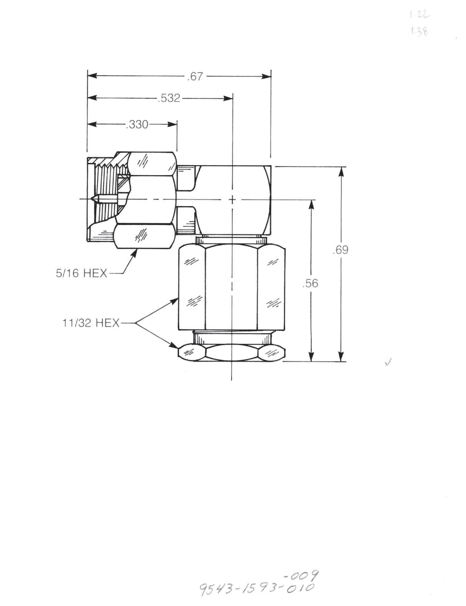
Right Angle Plug Solder clamp attachment
For 0.085˝ semi-rigid: 9543-1593-010 (Gold-plated)
9543-9593-010 (Passivated)
For 0.141˝ semi-rigid: 9543-1593-009 (Gold-plated)
9543-9593-009 (Passivated)
2-10 Visit www.radiall.com/AEP and enter the part number.

Straight Jack
Direct solder attachment
Non-captive contact
For 0.085˝ semi-rigid (A = 0.089): 9402-1083-010 (Gold-plated) 9402-7083-010 (Nickel-plated)
For 0.141˝ semi-rigid (A = 0.144):
9402-1083-009 (Gold-plated) 9402-7083-009 (Nickel-plated)

Straight Jack
Direct solder attachment
Captive contact for one-step cable assembly
For 0.085˝ semi-rigid (A = 0.089):
9402-1583-010 (Gold-plated)
9402-7583-010 (Nickel-plated)
For 0.141˝ semi-rigid (A = 0.144): 9402-1583-009 (Gold-plated) 9402-7583-009 (Nickel-plated)
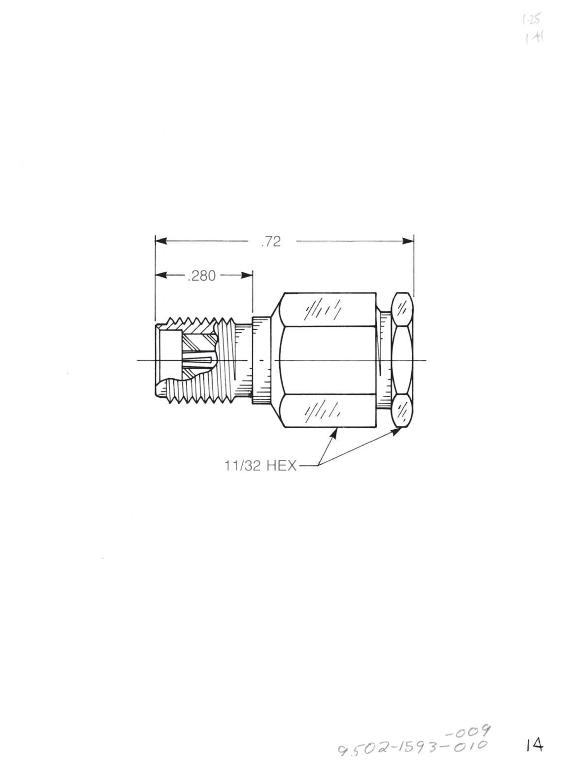
Straight Jack
Solder clamp attachment
Captive contact
For 0.085˝ semi-rigid:
9502-1593-010 (Gold-plated)
9502-9593-010 (Passivated)
For 0.141˝ semi-rigid:
9502-1593-009 (Gold-plated)
9502-9593-009 (Passivated)
2-11
Simplification is Our Innovation. Visit www.radiall.com/AEP and enter the part number.
SMA
Semi-Rigid Cable Jacks

Straight Bulkhead Jack

• Direct solder attachment
• With mounting gasket
• Non-captive contact
For 0.085˝ semi-rigid (A = 0.089)
9453-1083-010 (Gold-plated) 9453-7083-010 (Nickel-plated)
For 0.141˝ semi-rigid (A = 0.144): 9453-1083-009 (Gold-plated) 9453-7083-009 (Nickel-plated)
Straight Bulkhead Jack
• Direct solder attachment
• With mounting gasket
• Captive contact for one-step cable assembly
For 0.085˝ semi-rigid (A = 0.089): 9453-1583-010 (Gold-plated)
9453-7583-010 (Nickel-plated)
For 0.141˝ semi-rigid (A = 0.0144): 9453-1583-009 (Gold-plated) 9453-7583-009 (Nickel-plated)
Straight Bulkhead Jack
• Solder clamp attachment
• Captive contact
For 0.085˝ semi-rigid:
9530-1593-010 (Gold-plated)
9530-9593-010 (Passivated)
For 0.141˝ semi-rigid:
9530-1593-009 (Gold-plated)
9530-9593-009 (Passivated)
Right Angle Bulkhead Jack
• Direct solder attachment
For 0.085˝ semi-rigid (A = 0.089): 9613-1563-010 (Gold-plated)
9613-7563-010 (Nickel-plated)
For 0.141˝ semi-rigid (A = 0.144): 9613-1563-009 (Gold-plated)
9613-7563-009 (Nickel-plated
Designed for use with 0.125˝ max thick panel.
2-12 Visit www.radiall.com/AEP and enter the part number.
Semi-Rigid Cable Jacks
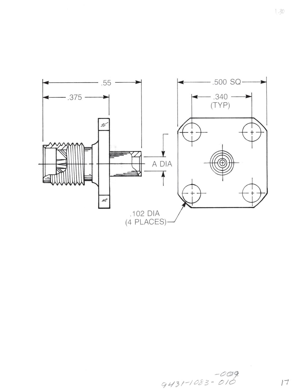
Straight Panel Jack
• Direct solder attachment
• Square flange
• Non-captive contact
For 0.085˝ semi-rigid (A = 0.089): 9431-1083-01O (Gold-plated) 9431-7083-010 (Nickel-plated)
For 0.141˝ semi-rigid (A = 0.144): 9431-1083-009 (Gold-plated) 9431-7083-009 (Nickel-plated)
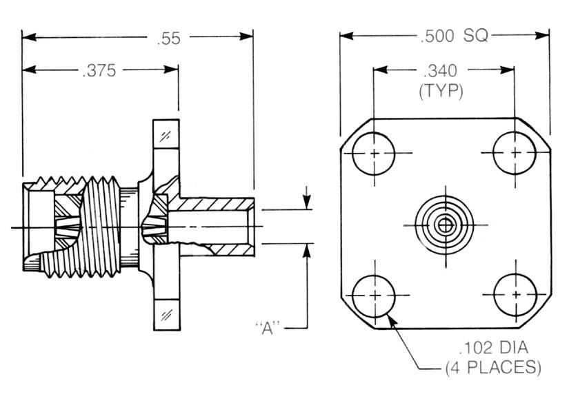
Straight Panel Jack
• Direct solder attachment
• Square flange
• Captive contact for one-step cable assembly
For 0.085˝ semi-rigid (A = 0.089): 9431-1583-010 (Gold-plated) 9431-7583-010 (Nickel-plated)
For 0.141˝ semi-rigid (A = 0.144) 9431-1583-009 (Gold-plated) 9431-7583-009 (Nickel-plated)
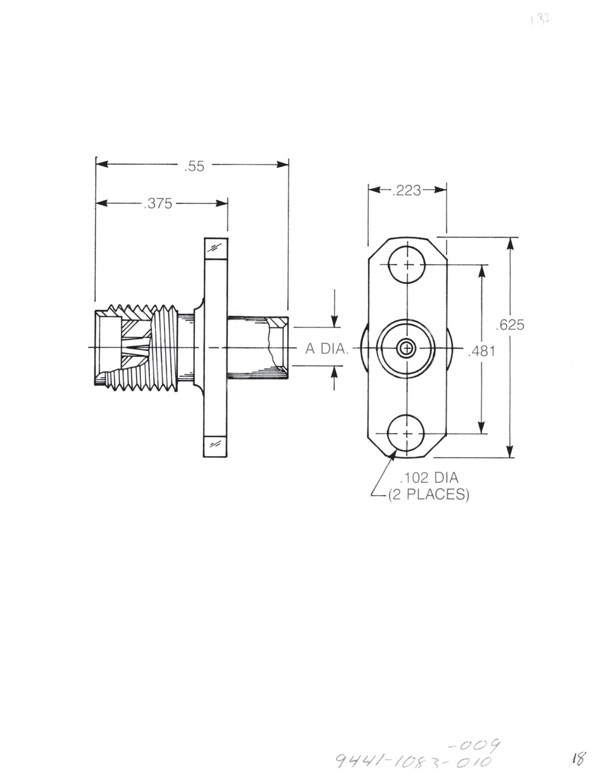
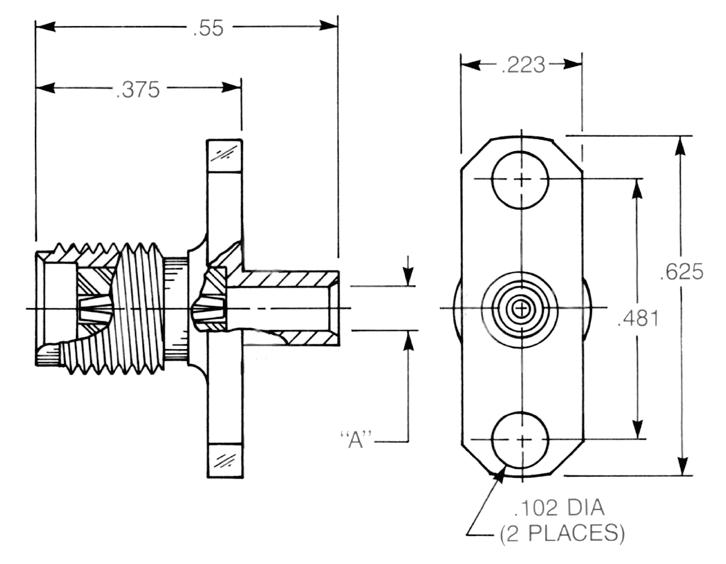
Straight Panel Jack
• Direct solder attachment
• 2-hole flange
• Non-captive contact
For 0.085˝ semi-rigid (A = 0.089): 9441-1083-010 (Gold-plated) 9441-7083-010 (Nickel-plated)
For 0.141˝ semi-rigid (A = 0.144): 9441-1083-009 (Gold-plated) 9441-7083-009 (Nickel-plated)
Straight Panel Jack
• Direct solder attachment
• 2-hole flange
• Captive contact for one-step cable assembly
For 0.085˝ semi-rigid (A = 0.089): 9441-1583-010 (Gold-plated) 9441-7583-010 (Nickel-plated)
For 0.141˝ semi-rigid (A = 0.144): 9441-1583-009 (Gold-plated) 9441-7583-009 (Nickel-plated)
2-13
Simplification is Our Innovation. Go online for data sheets and assembly instructions. Visit www.radiall.com/AEP and enter the part number.
SMA
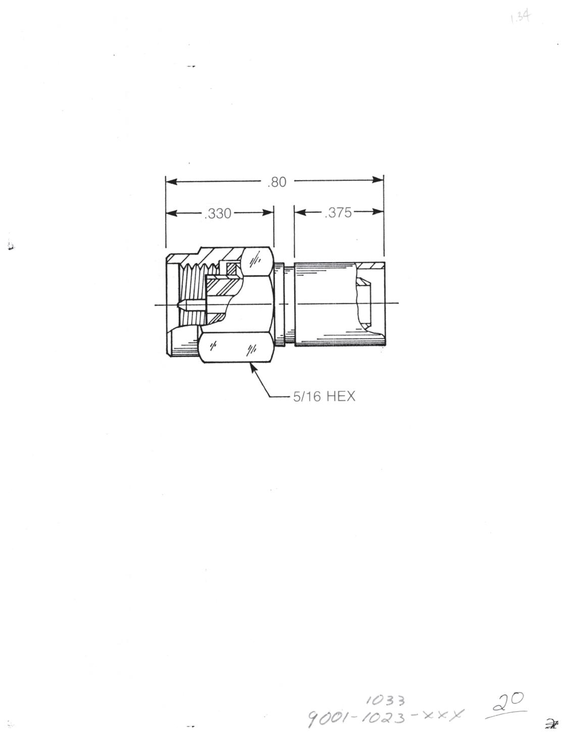

Straight Plug
• Non-captive contact
Crimp type:
9001-1023-0XX (Gold-plated)
9001-9023-0XX (Passivated)
Solder type:
9001-1033-0XX (Gold-plated)
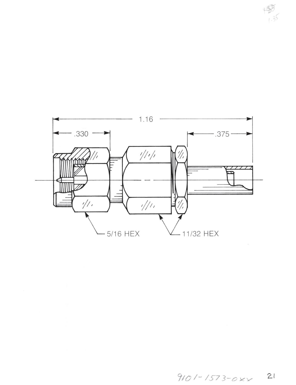
Straight Plug
• Captive contact
Crimp type:
9101-1573-0XX (Gold-plated)
9101-9573-0XX (Passivated)
Straight Plug
• Captive contact
Clamp type:
9201-1553-0XX (Gold-plated)
9201-9553-0XX (Passivated)
Substitute XX with the Appropriate Cable Group Below
01 RG142, RG223, M17/60, M17/84, M17/158 04 RG180, RG195, M17/95
02 RG178, RG196, M17/93, M17/169 05 RG178DS, RG196DS
03 RG174, RG179, RG316, M17/113, M17/119, M17/172, M17/173
06 RG58, RG141, RG303, M17/111, M17/155 19 RG174DS, RG316DS, M17/152, Times RD316
A Dim = 0.303 for cable groups 01, 04 and 06
A Dim = 0.375 for cable groups 02, 03, 05 and 19
2-14 Go online for data sheets and assembly instructions. Visit www.radiall.com/AEP and enter the part number.
A
A
Flexible Cable Plugs
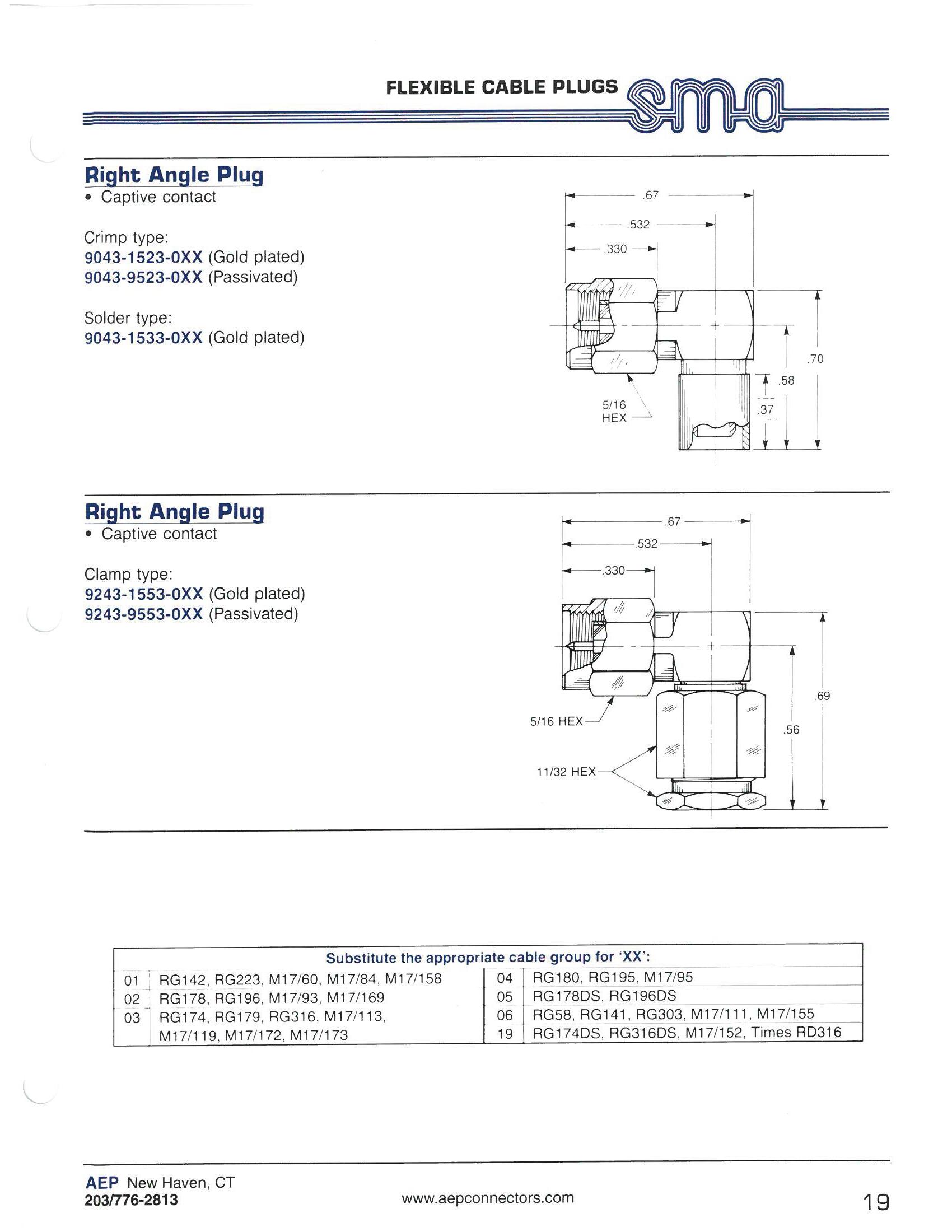
Right Angle Plug
• Captive contact
Crimp type:
9043-1523-0XX (Gold-plated) 9043-9523-0XX (Passivated)
Solder type:
9043-1533-0XX (Gold-plated)
Right Angle Plug
• Captive contact
Clamp type:
9243-1553-0XX (Gold-plated) 9243-9553-0XX (Passivated)
Substitute XX with the Appropriate Cable Group Below
01 RG142, RG223, M17/60, M17/84, M17/158 04 RG180, RG195, M17/95
02 RG178, RG196, M17/93, M17/169
03 RG174, RG179, RG316, M17/113, M17/119, M17/172, M17/173
05 RG178DS, RG196DS
06 RG58, RG141, RG303, M17/111, M17/155
19 RG174DS, RG316DS, M17/152, Times RD316
2-15 SMA Simplification is
Go online for data sheets and assembly instructions. Visit www.radiall.com/AEP and enter the part number.
Our Innovation.
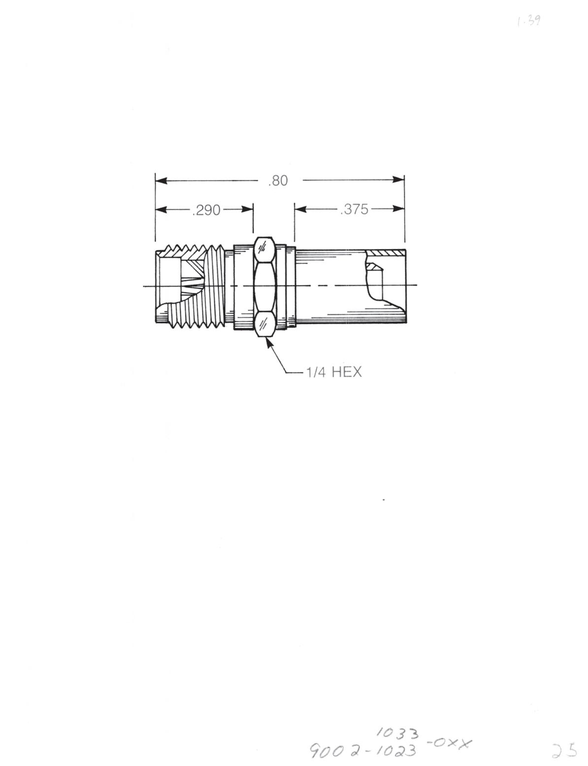
Straight Jack
• Non-captive contact
Crimp type:
9002-1023-0XX (Gold-plated) 9002-9023-0XX (Passivated)
Solder type:
9002-1033-0XX (Gold-plated)
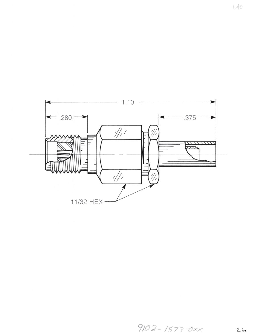
Straight Jack
• Captive contact
Crimp type:
9102-1573-0XX (Gold-plated) 9102-9573-0XX (Passivated)
Straight Jack
• Captive contact
Clamp type:
9202-1553-0XX (Gold-plated) 9202-9553-0XX (Passivated)
Substitute XX with the Appropriate Cable Group Below
01 RG142, RG223, M17/60, M17/84, M17/158 04 RG180, RG195, M17/95
02 RG178, RG196, M17/93, M17/169 05 RG178DS, RG196DS
03 RG174, RG179, RG316, M17/113, M17/119, M17/172, M17/173
06 RG58, RG141, RG303, M17/111, M17/155 19 RG174DS, RG316DS, M17/152, Times RD316
A Dim = 0.303 for cable groups 01, 04 and 06
A Dim = 0.375 for cable groups 02, 03, 05 and 19
2-16 Go online for data sheets and assembly instructions. Visit www.radiall.com/AEP and enter the part number.
A A
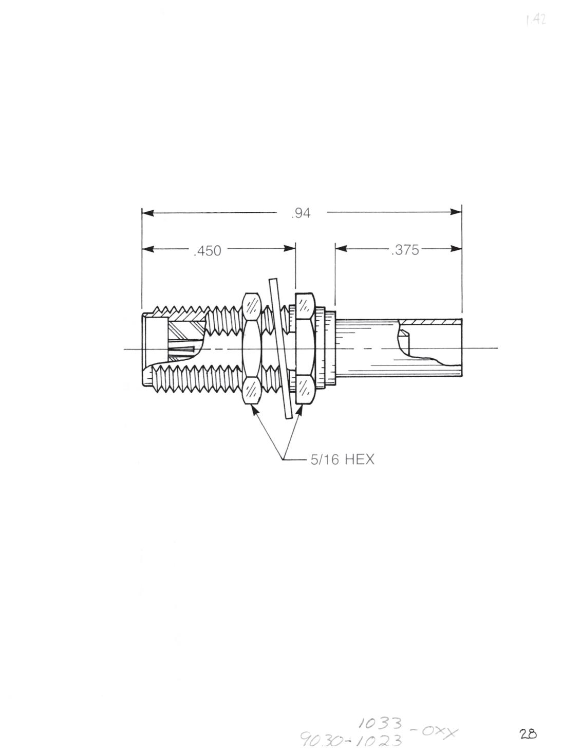


Straight Bulkhead Jack • Non-captive contact
Crimp type:
9030-1023-0XX (Gold-plated) 9030-9023-0XX (Passivated)
Solder type: 9030-1033-0XX (Gold-plated)
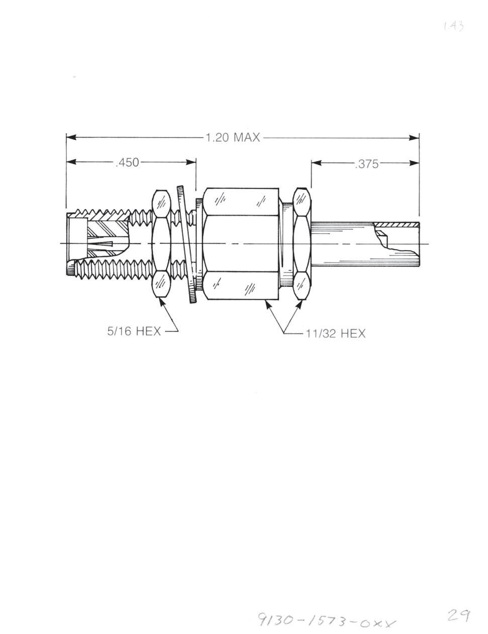
Straight Bulkhead Jack • Captive contact
Crimp type:
9130-1573-0XX (Gold-plated) 9130-9573-0XX (Passivated)
Straight Bulkhead Jack • Captive contact
Clamp type:
9230-1553-0XX (Gold-plated) 9230-9553-0XX (Passivated)
Right Angle Bulkhead Jack
Crimp type:
9613-1523-0XX (Gold-plated) 9613-9523-0XX (Passivated)
Substitute XX with the Appropriate Cable Group Below
01 RG142, RG223, M17/60, M17/84, M17/158 04 RG180, RG195, M17/95
02 RG178, RG196, M17/93, M17/169
03 RG174, RG179, RG316, M17/113, M17/119, M17/172, M17/173
05 RG178DS, RG196DS
06 RG58, RG141, RG303, M17/111, M17/155
19 RG174DS, RG316DS, M17/152, Times RD316
A Dim = 0.303 for cable groups 01, 04 and 06
A Dim = 0.375 for cable groups 02, 03, 05 and 19 Designed for use with 0.125˝ max thick panel.
2-17 SMA Simplification
Go online for data sheets and assembly instructions. Visit www.radiall.com/AEP and enter the part number.
is Our Innovation.
A A

Straight Panel Jack
• Non-captive contact
• Square flange
Crimp type: 9031-1023-0XX (Gold-plated) 9031-9023-0XX (Passivated)
Solder type: 9031-1033-0XX (Gold-plated)
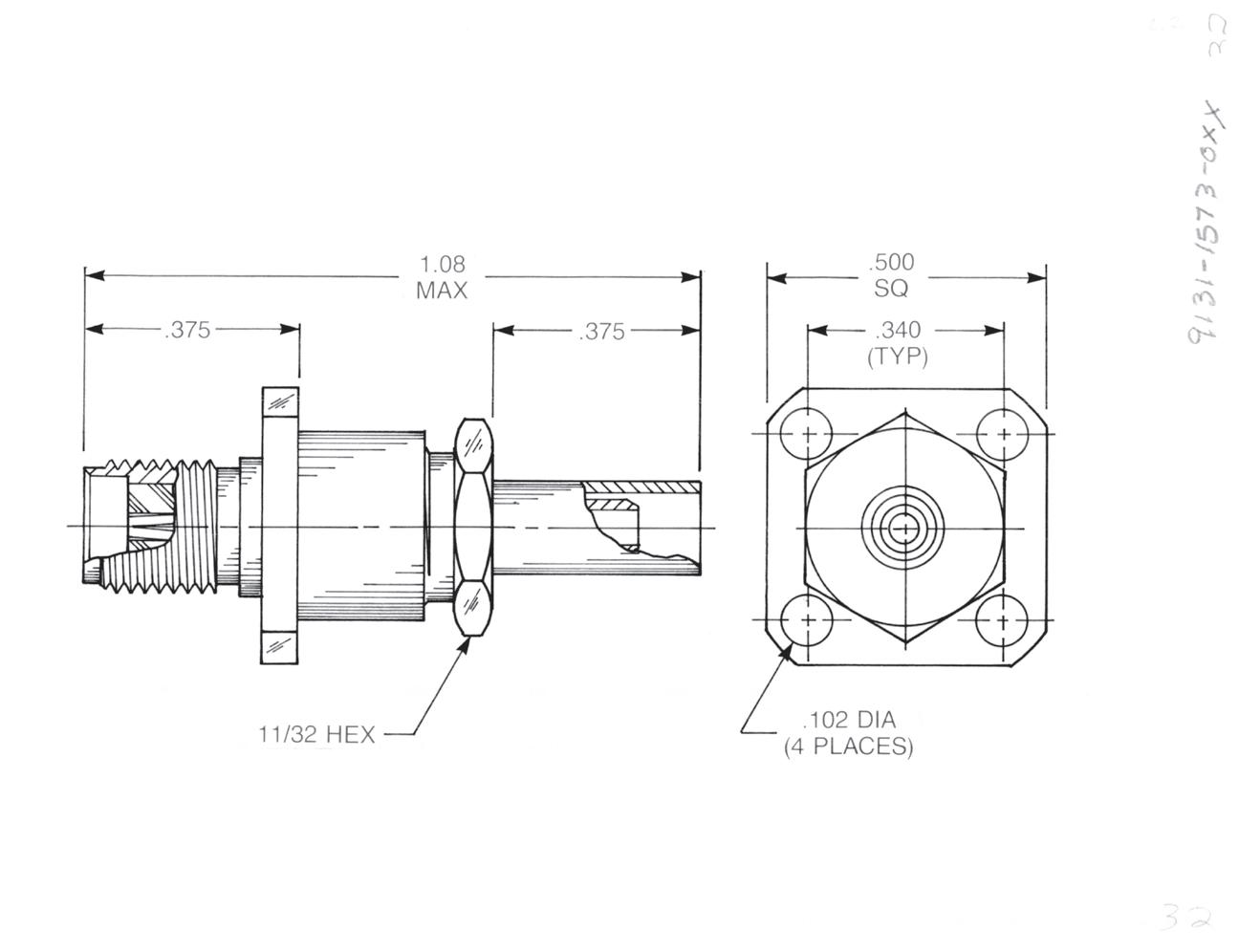
Straight Panel Jack
• Captive contact
• Square flange
Crimp type: 9131-1573-0XX (Gold-plated) 9131-9573-0XX (Passivated)
Straight Panel Jack
• Captive contact
• Square flange
Clamp type: 9231-1553-0XX (Gold-plated) 9231-9553-0XX (Passivated)
Substitute XX with the Appropriate Cable Group Below
01 RG142, RG223, M17/60, M17/84, M17/158 04 RG180, RG195, M17/95
02 RG178, RG196, M17/93, M17/169 05 RG178DS, RG196DS
03 RG174, RG179, RG316, M17/113, M17/119, M17/172, M17/173
06 RG58, RG141, RG303, M17/111, M17/155 19 RG174DS, RG316DS, M17/152, Times RD316
A Dim = 0.303 for cable groups 01, 04 and 06
A Dim = 0.375 for cable groups 02, 03, 05 and 19
2-18
Go online for data sheets and assembly instructions. Visit www.radiall.com/AEP and enter the part number.
SMA
A
A
Flexible Cable Jacks
Panel Jack Receptacles
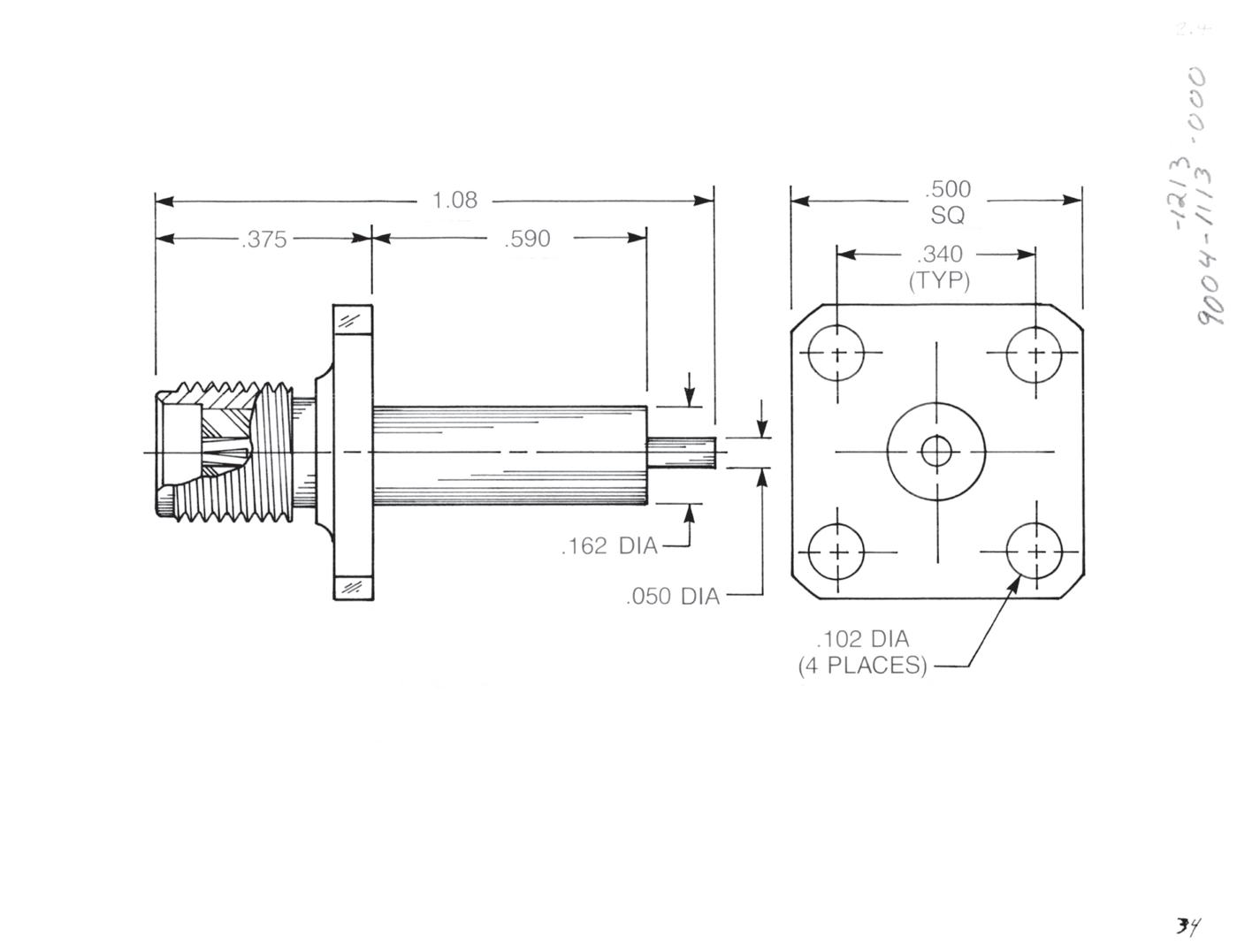
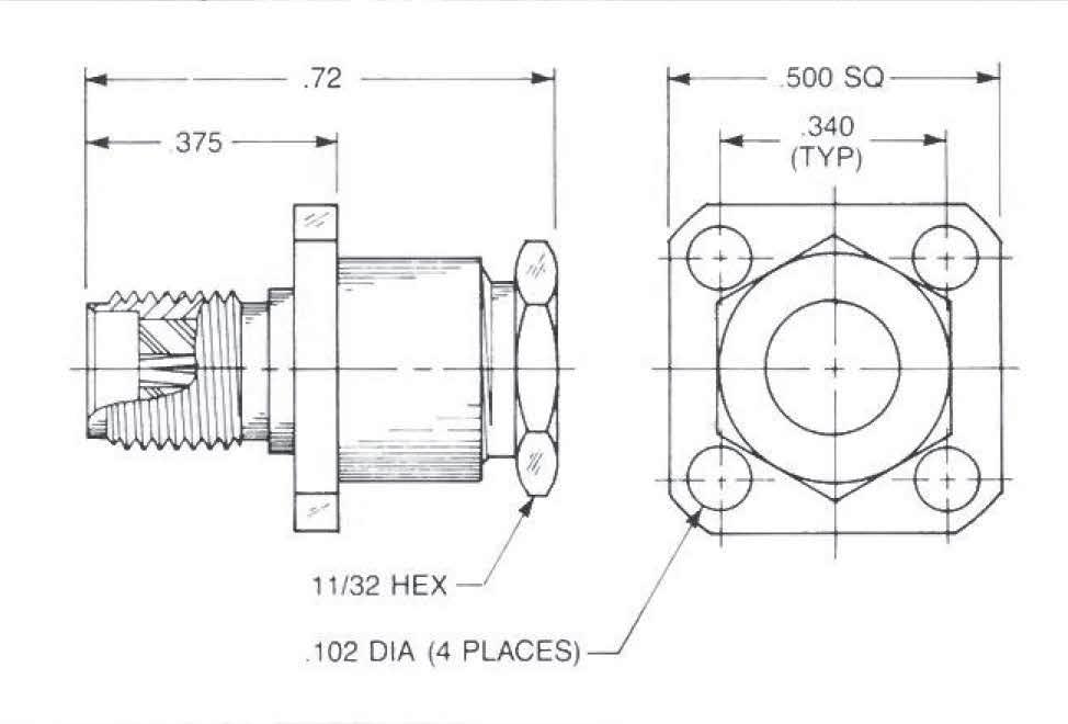
Straight Panel Jack Receptacle
• Extended contact and insulator
• ½˝ square flange
Captive contact:
9004-1113-000 (Gold-plated)
9004-9113-000 (Passivated)
Non-captive contact:
9004-1213-000 (Gold-plated)
9004-9213-000 (Passivated)
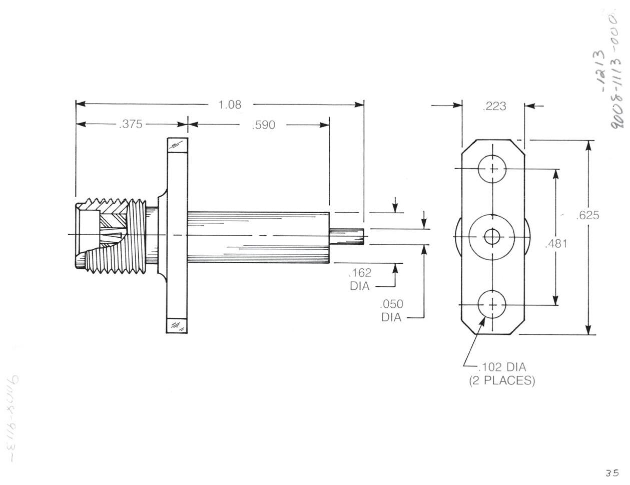
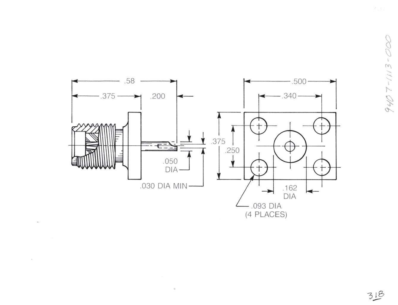
Straight Panel Jack Receptacle
• Extended contact and insulator
• 2-hole flange
Captive contact:
9008-1113-000 (Gold-plated)
9008-9113-000 (Passivated)

Non-captive contact:
9008-1213-000 (Gold-plated)
9008-9213-000 (Passivated)
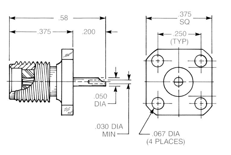
Straight Panel Jack Receptacle
Extended contact and insulator ˝ square flange
Captive contact:
9076-1113-000 (Gold-plated)
9076-9113-000 (Passivated)
Non-captive contact:
9076-1213-000 (Gold-plated)
9076-9213-000 (Passivated)
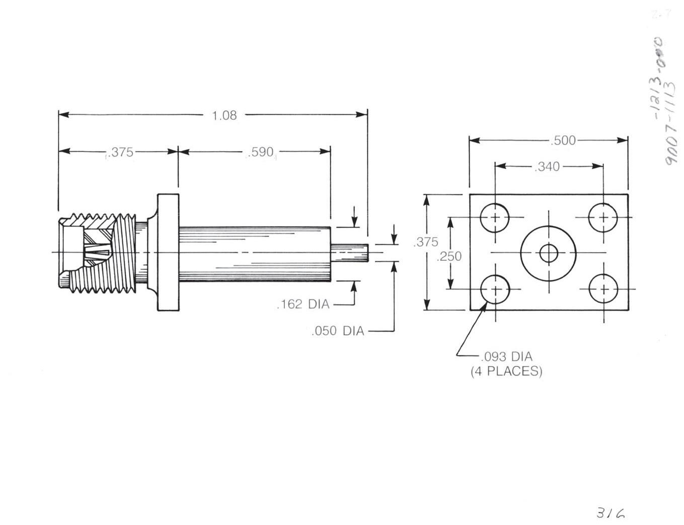
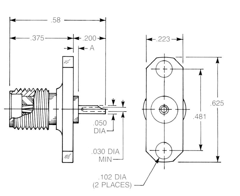
Straight Panel Jack Receptacle
Extended contact and insulator
Rectangular flange
Captive contact:
9007-1113-000 (Gold-plated)
9007-9113-000 (Passivated)
Non-captive contact:
9007-1213-000 (Gold-plated)
9007-9213-000 (Passivated)
Additional contact and insulator diameters and lengths available upon request.
2-19
Simplification is Our Innovation. Go online for data sheets and assembly instructions. Visit www.radiall.com/AEP and enter the part number.
SMA
SMA
Panel Jack Receptacles
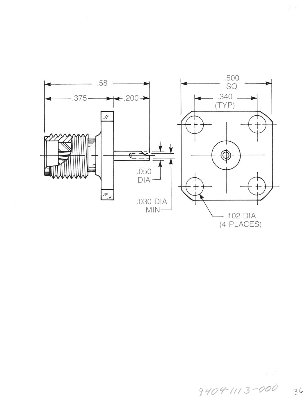
Straight Panel Jack Receptacle
• Solder pot contact
• ½˝ square flange
Captive contact:
9404-1113-000 (Gold-plated) 9404-9113-000 (Passivated)
Straight Panel Jack Receptacle
• Solder pot contact
• 2-hole flange
Captive contact (A = 0.030): 9408-1113-000 (Gold-plated) 9408-9113-000 (Passivated)
Captive contact (A = 0.000): 9408-1113-002 (Gold-plated) 9408-9113-002 (Passivated)
Straight Panel Jack Receptacle
• Solder pot contact
• ³⁄8˝ square flange
Captive contact:
9476-1113-000 (Gold-plated) 9476-9113-000 (Passivated)
Straight Panel Jack Receptacle
• Solder pot contact
• Rectangular flange
Captive contact: 9407-1113-000 (Gold-plated) 9407-9113-000 (Passivated)
2-20
Go online for data sheets and assembly instructions. Visit www.radiall.com/AEP and enter the part number.
Panel Jack Receptacles
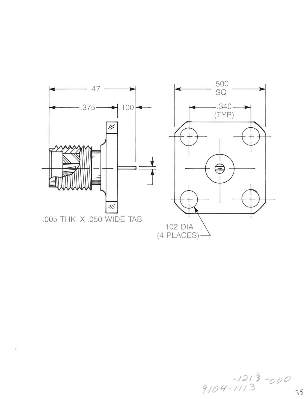

Straight Panel Jack Receptacle
• Tab contact
• ½˝ square flange
Captive contact:
9104-1113-000 (Gold-plated)
9104-9113-000 (Passivated)
Non-captive contact:
9104-1213-000 (Gold-plated)
9104-9213-000 (Passivated)
Straight Panel Jack Receptacle
• Tab contact
• 2-hole flange
Captive contact:
9108-1113-000 (Gold-plated)
9108-9113-000 (Passivated)
Non-captive contact:
9108-1213-000 (Gold-plated)
9108-9213-000 (Passivated)
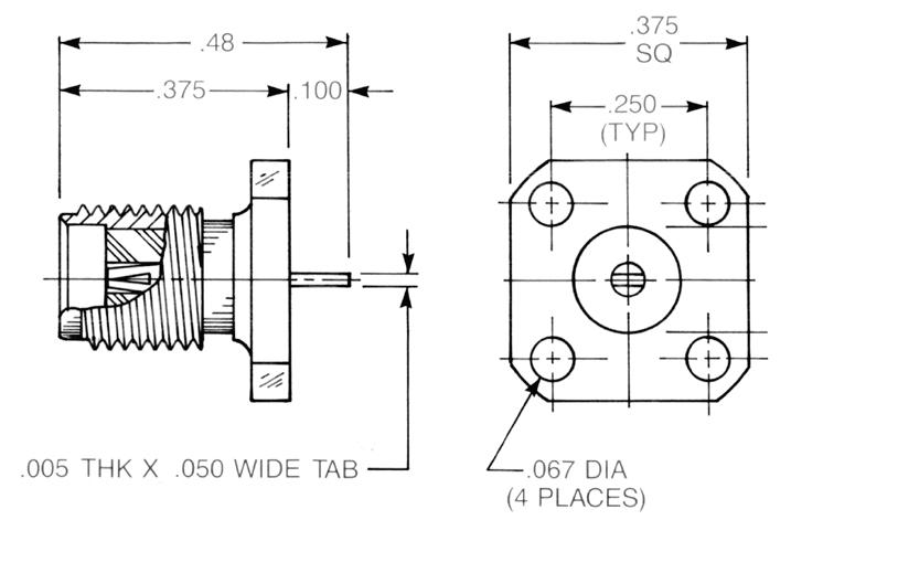
Straight Panel Jack Receptacle
• Tab contact
• ³⁄8˝ square flange
Captive contact:
9176-1113-000 (Gold-plated)
9176-9113-000 (Passivated)
Non-captive contact: 9176-1213-000 (Gold-plated)
9176-9213-000 (Passivated)
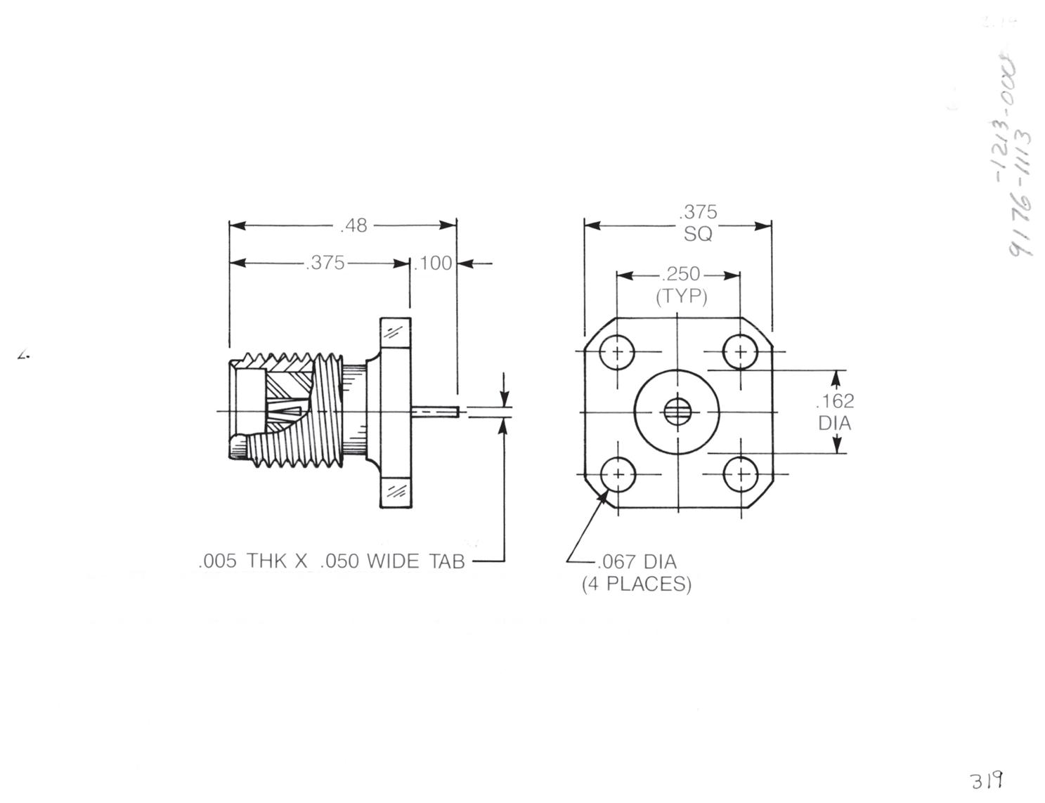
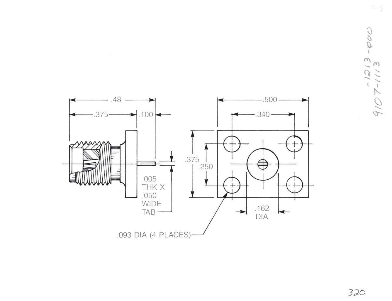
Straight Panel Jack Receptacle
• Tab contact
• Rectangular flange
Captive contact:
9107-1113-000 (Gold-plated)
9107-9113-000 (Passivated)
Non-captive contact:
9107-1213-000 (Gold-plated)
9107-9213-000 (Passivated)
Additional tab contacts available in other lengths, widths and thicknesses.
2-21
Simplification is
Go online for data sheets and assembly instructions. Visit www.radiall.com/AEP and enter the part number.
SMA
Our Innovation.
Panel Jack Receptacles
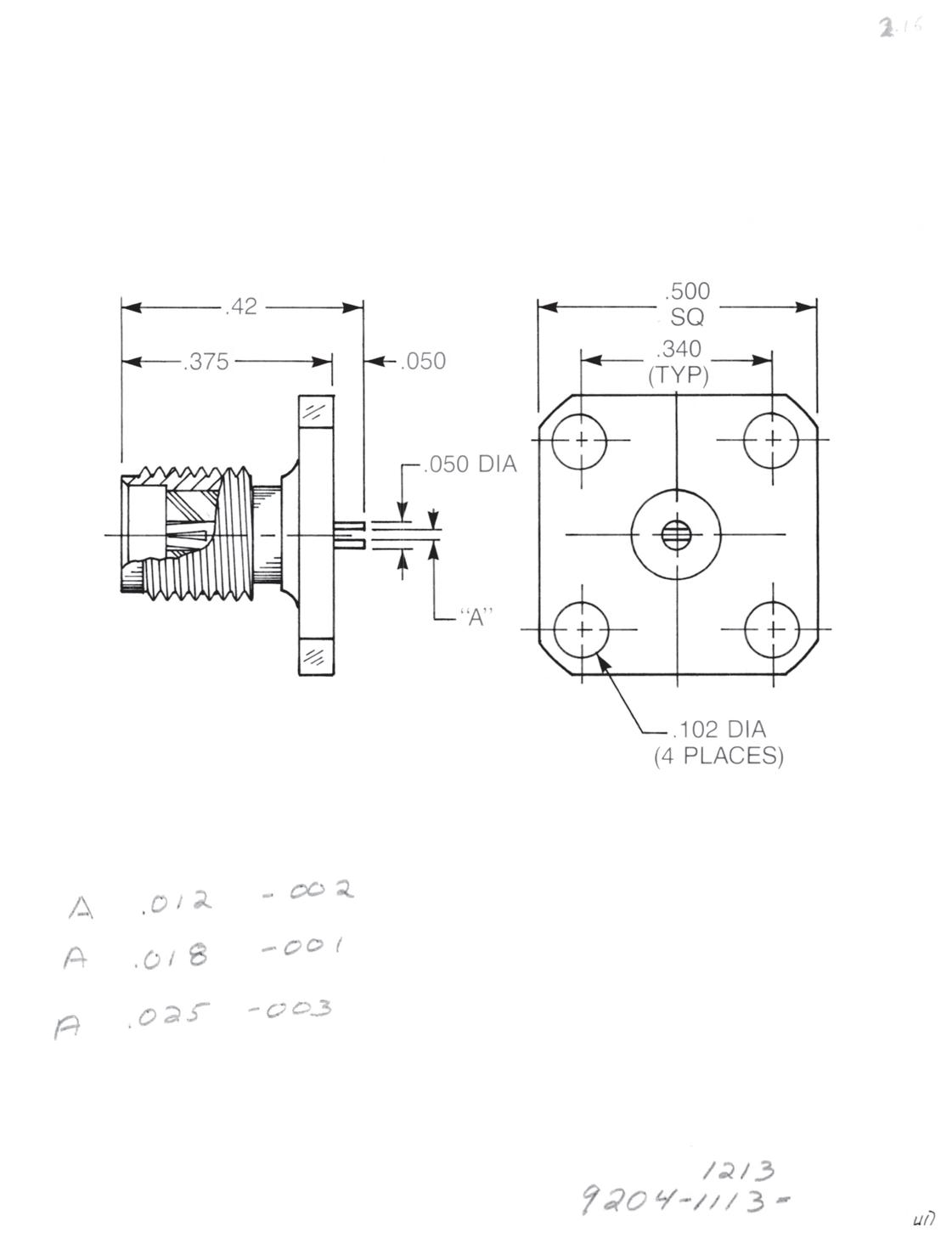
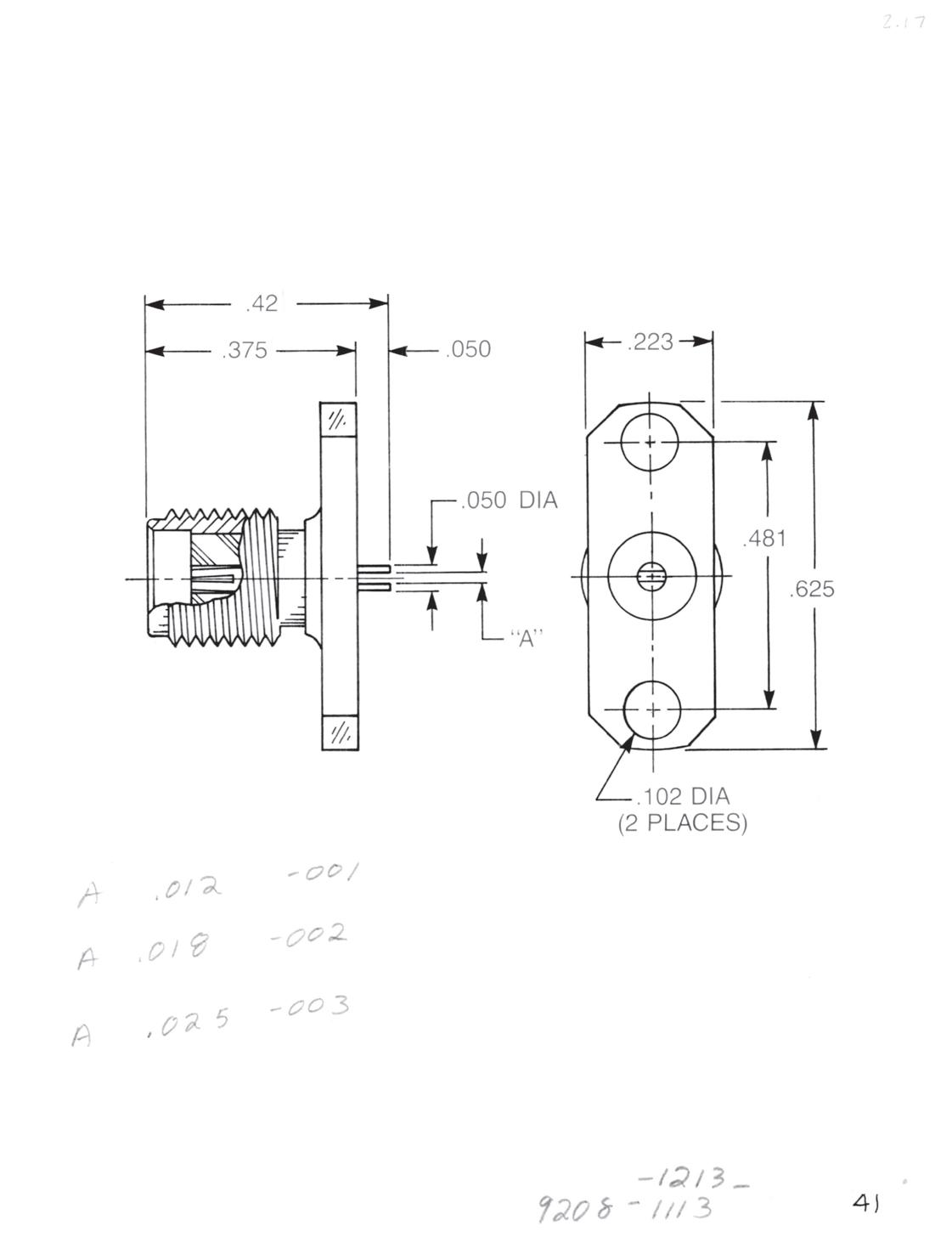
Straight Panel Jack Receptacle
• Slotted contact
• ½˝ square flange
Dim. A Captive contact:
0.012 9204-1113-002 (Gold-plated)
9204-9113-002 (Passivated)
0.018 9204-1113-001 (Gold-plated)
9204-9113-001 (Passivated)
0.025 9204-1113-003 (Gold-plated)
9204-9113-003 (Passivated)
Non-captive contact:
0.012 9204-1213-002 (Gold-plated)
9204-9213-002 (Passivated)
0.018 9204-1213-001 (Gold-plated)
9204-9213-001 (Passivated)
0.025 9204-1213-003 (Gold-plated)
9204-9213-003 (Passivated)
Straight Panel Jack Receptacle
• Slotted contact
• 2-hole flange
Dim. A Captive contact:
0.012 9208-1113-000 (Gold-plated)
9208-9113-000 (Passivated)
0.018 9208-1113-001 (Gold-plated)
9208-9113-001 (Passivated)
0.025 9208-1113-002 (Gold-plated)
9208-9113-002 (Passivated)
Non-captive contact:
0.012 9208-1213-000 (Gold-plated)
9208-9213-000 (Passivated)
0.018 9208-1213-001 (Gold-plated)
9208-9213-001 (Passivated)
0.025 9208-1213-002 (Gold-plated)
9208-9213-002 (Passivated)
Slotted contacts available in other widths and depths.
2-22
Go online for data sheets and assembly instructions. Visit www.radiall.com/AEP and enter the part number.
SMA
Panel Jack Receptacles
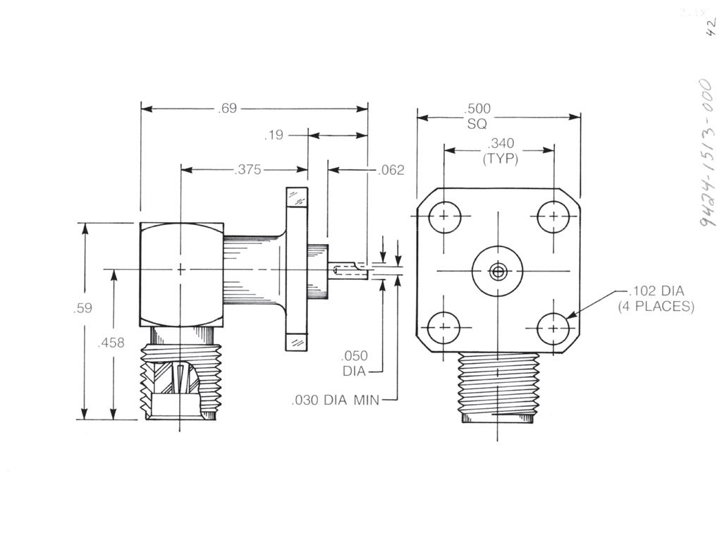
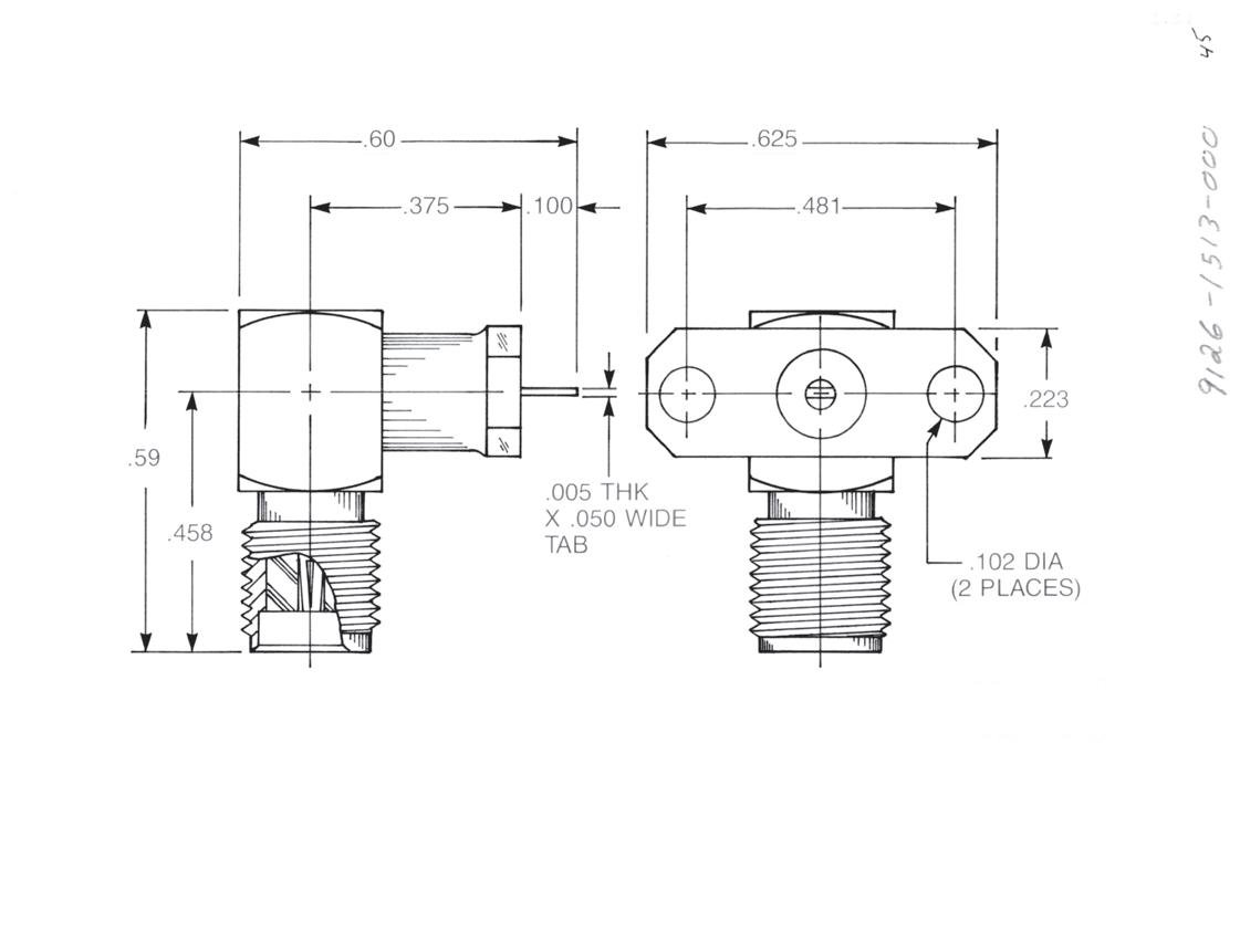
Right Angle Panel Jack Receptacle
• Solder pot contact
• ½˝ square flange
9424-1513-000 (Gold-plated) 9424-9513-000 (Passivated)
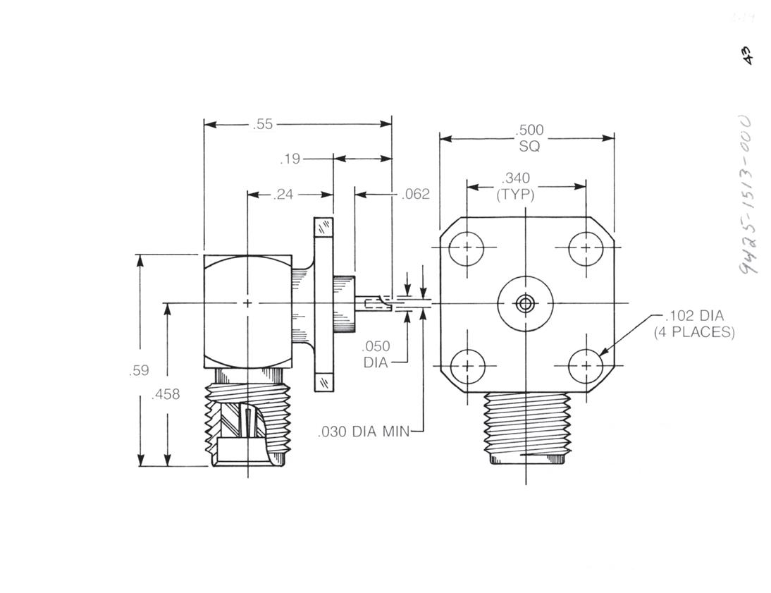
Low Profile Right Angle Panel Jack Receptacle
• Solder pot contact
• ½˝ square flange
9425-1513-000 (Gold-plated)
9425-9513-000 (Passivated)
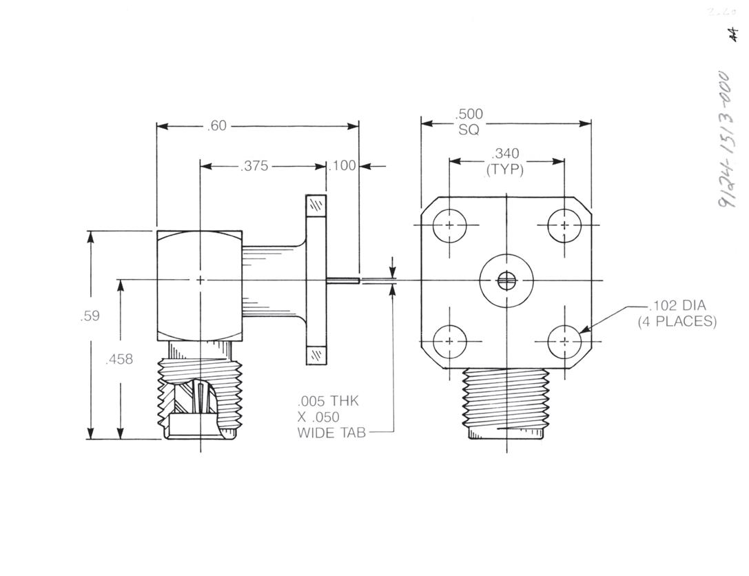
Right Angle Panel Jack Receptacle
• Tab contact
• ½˝ hole flange
9124-1513-000 (Gold-plated)
9124-9513-000 (Passivated)
Right Angle Panel Jack Receptacle
• Tab contact
• 2-hole flange
9126-1513-000 (Gold-plated)
9126-9513-000 (Passivated)
2-23
Simplification is
Innovation. Go online for data sheets and assembly instructions. Visit www.radiall.com/AEP and enter the part number.
SMA
Our
SMA
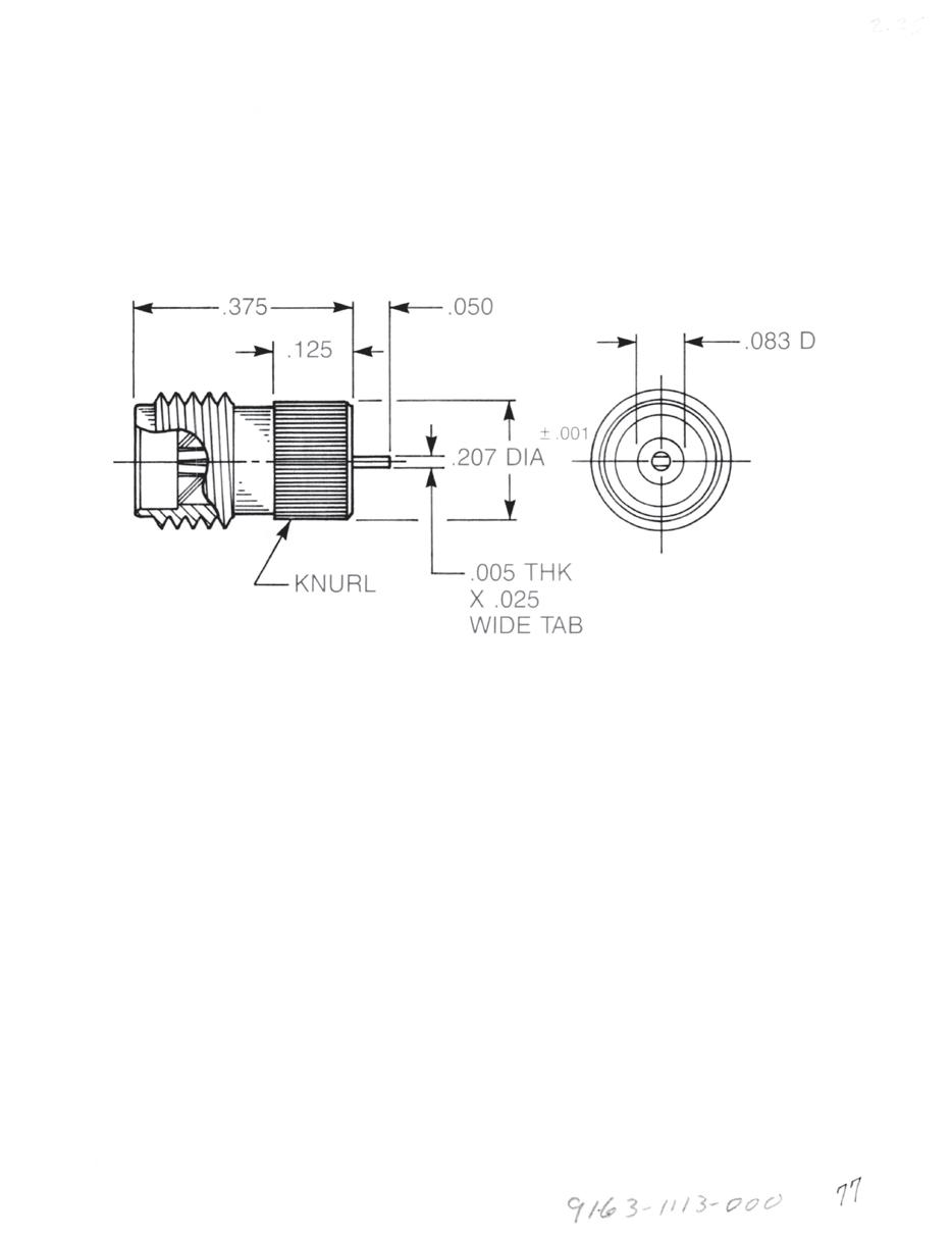
Receptacles for 0.025˝ Microstrip
Standard SMA receptacles with tab contacts have the tab milled from a 0.050˝ diameter round contact. This 0.050˝ diameter is flush with the rear insulator of the connector.
When these connectors are used with 0.025˝ thick microstrip, a capacitive coupling can be introduced because of the close proximity of the microstrip ground plane to the 0.050˝ diameter.
These receptacles eliminate the coupling by reducing the contact rear diameter to 0.025˝. The insulator diameter at the rear of the connector is reduced to 0.08 3˝ to maintain 50 ohm impedance.
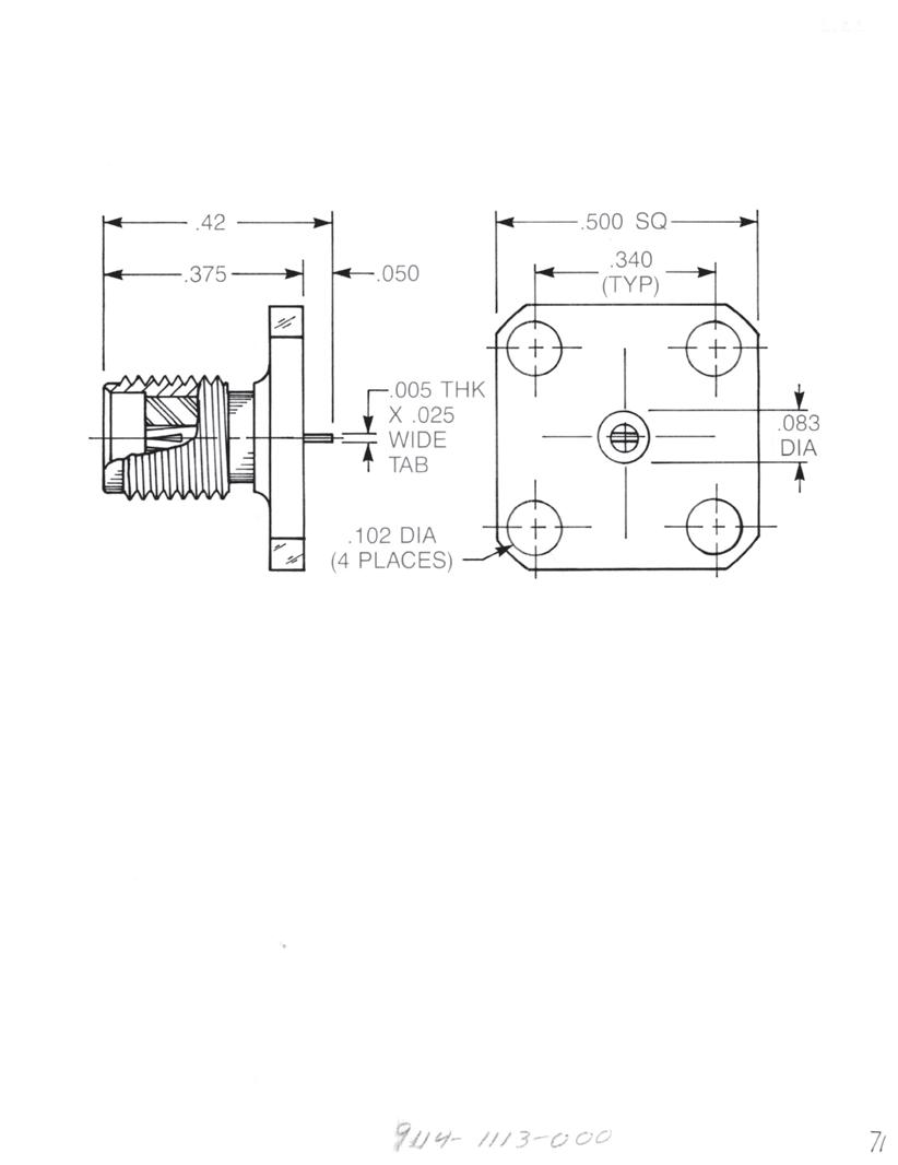
Straight Jack Receptacle
• ½˝ square flange
Captive contact: 9114-1113-000 (Gold-plated) 9114-9113-000 (Passivated)
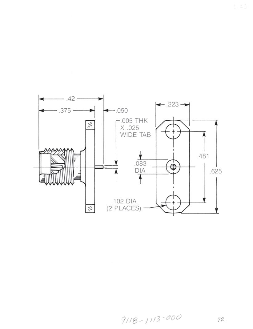
Straight Jack Receptacle
• 2-hole flange
Captive contact:
9118-1113-000 (Gold-plated) 9118-9113-000 (Passivated)
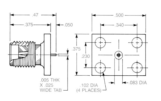
Straight Jack Receptacle
• Rectangular flange
Captive contact: 9117-1113-000 (Gold-plated) 9117-9113-000 (Passivated)
Straight Jack Receptacle
• Knurl mount
Captive contact:
9163-1113-000 (Gold-plated) 9163-9113-000 (Passivated)
2-24
Visit www.radiall.com/AEP and enter the part number.
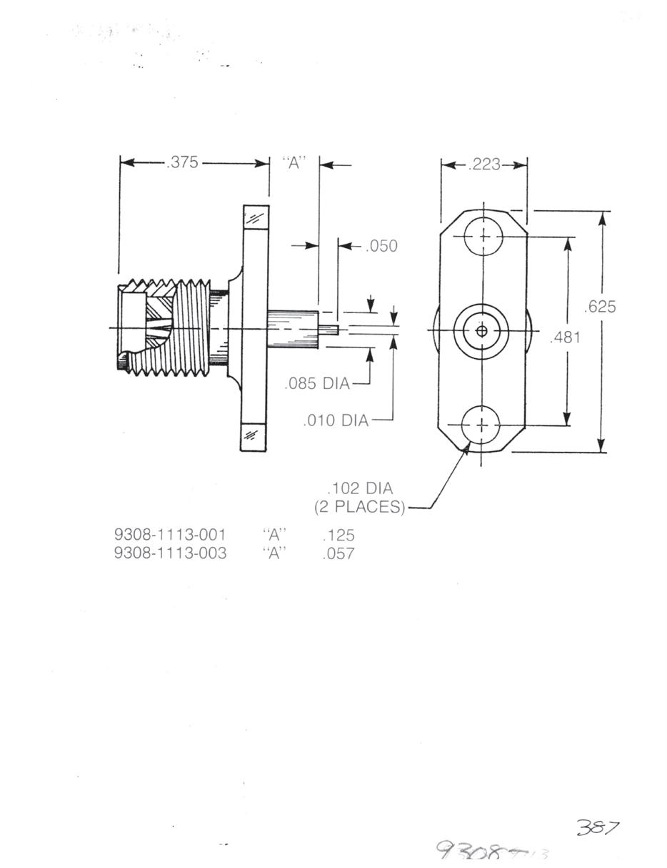
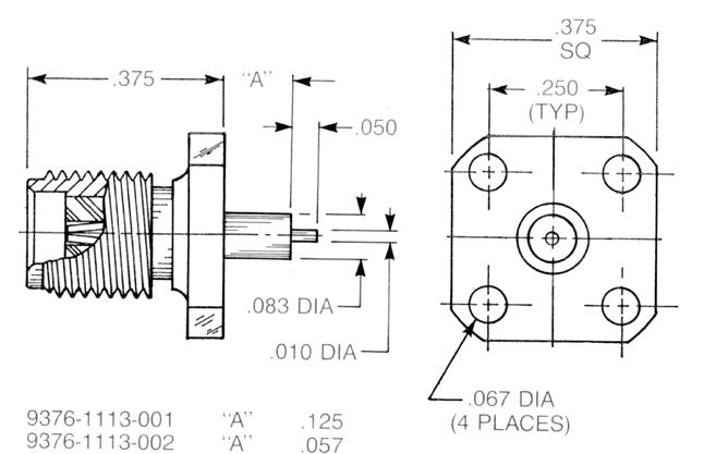
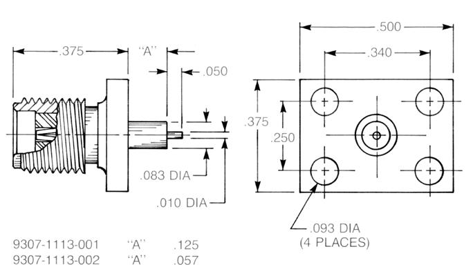
Receptacles for 0.010˝ Microstrip
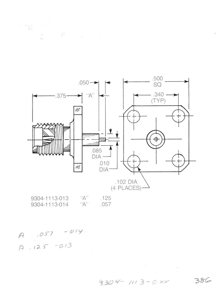
The receptacles shown below have 0.010˝ diameter contacts for good electrical transition to narrow microstrip lines. The reduced-diameter insulators are extended beyond the flange face to carry 50 ohm impedance through the microstrip package wall. All have captive contacts.
Straight Jack Receptacle
• ½˝ square flange
A = 0.057: 9304-1113-014 (Gold-plated) 9304-9113-014 (Passivated)
A = 0.0125: 9304-1113-013 (Gold-plated) 9304-9113-013 (Passivated)
Straight Jack Receptacle
• 2-hole flange
A = 0.057: 9308-1113-003 (Gold-plated) 9308-9113-003 (Passivated)
A = 0.125: 9308-1113-001 (Gold-plated) 9308-9113-001 (Passivated)
Straight Jack Receptacle
• ³⁄8˝ square flange
A = 0.057: 9376-1113-002 (Gold-plated) 9376-9113-002 (Passivated)
A = 0.125: 9376-1113-001 (Gold-plated) 9376-9113-001 (Passivated)
Straight Jack Receptacle
• Rectangular flange
A = 0.057: 9307-1113-002 (Gold-plated) 9307-9113-002 (Passivated)
A = 0.125: 9307-1113-001 (Gold-plated) 9307-9113-001 (Passivated)
2-25
Go online for data sheets and assembly instructions. Visit www.radiall.com/AEP and enter the part number.
SMA Simplification is Our Innovation.
SMA
Panel Plug Receptacles
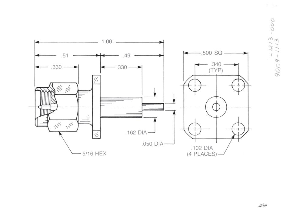
Straight Panel Plug Receptacle
• Extended contact and insulator
• ½˝ square flange
Captive contact:

2-26
Go online for data sheets and assembly instructions. Visit www.radiall.com/AEP and enter the part number.
Panel Plug Receptacles
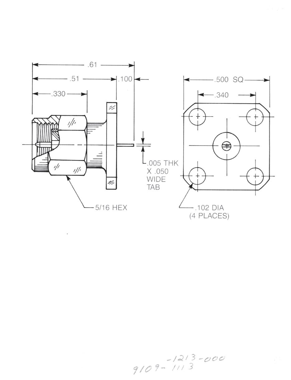
Straight Panel Plug Receptacle
• Tab contact
• ½˝ square flange
Captive contact:
9109-1113-000 (Gold-plated)
9109-9113-000 (Passivated)
Non-captive contact:
9109-1213-000 (Gold-plated)
9109-9213-000 (Passivated)
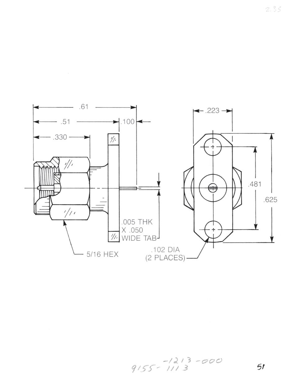
Straight Panel Plug Receptacle
• Tab contact
• 2-hole flange
Captive contact:
9155-1113-000 (Gold-plated)
9155-9113-000 (Passivated)
Non-captive contact:
9155-1213-000 (Gold-plated)
9155-9213-000 (Passivated)
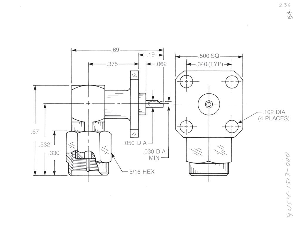
Right Angle Panel Plug Receptacle
• Solder pot contact
• ½˝ square flange
9454-1513-000 (Gold-plated)
9454-9513-000 (Passivated)
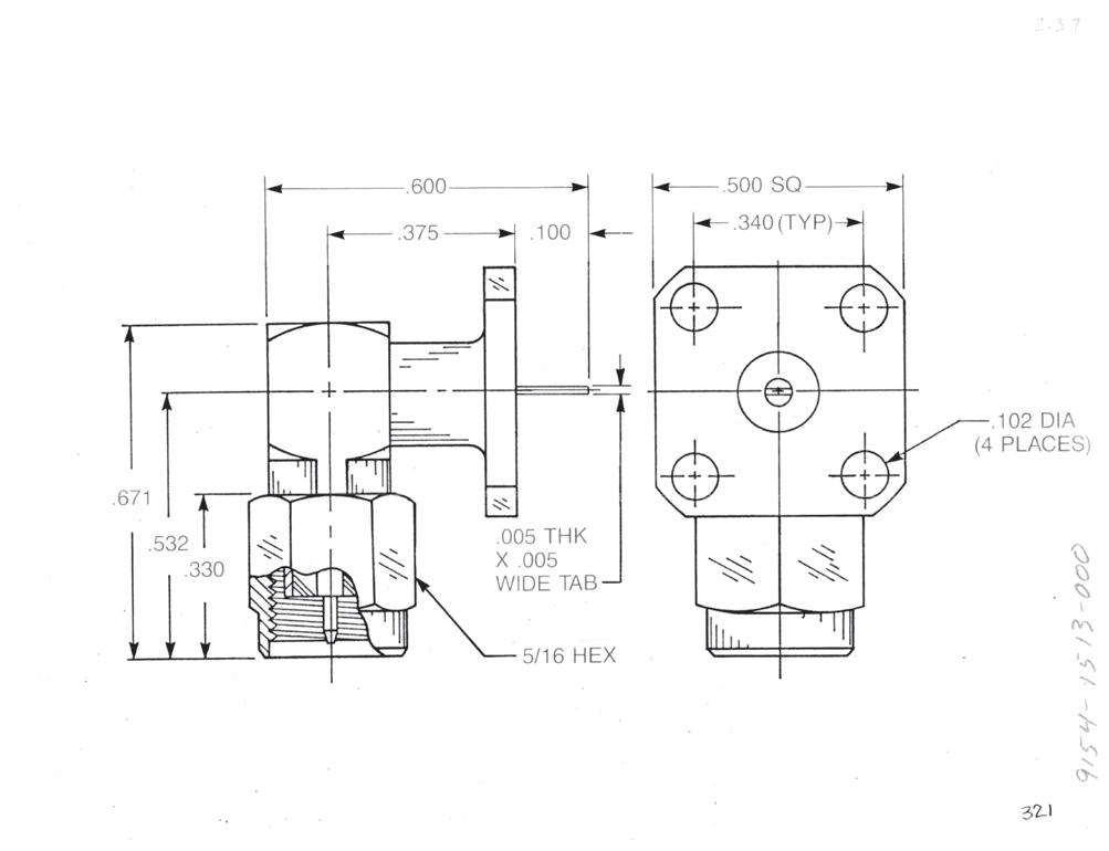
Right Angle Panel Plug Receptacle
• Tab contact
• ½˝ square flange
9154-1513-000 (Gold-plated)
9154-9513-000 (Passivated)
Additional contact and insulator configurations available upon request.
2-27
Simplification
Go online for data sheets and assembly instructions. Visit www.radiall.com/AEP and enter the part number.
SMA
is Our Innovation.
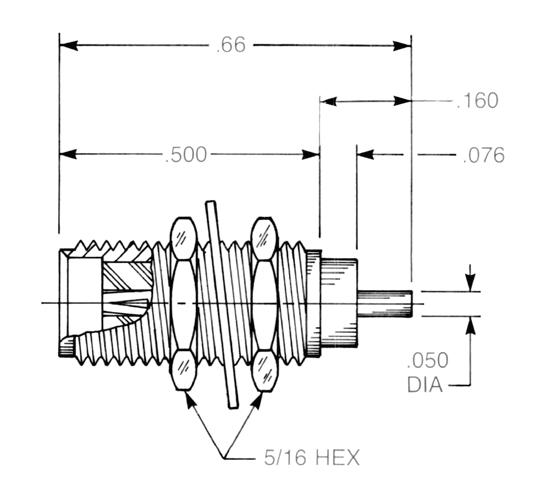
Bulkhead Jack Receptacles
Straight Bulkhead Jack Receptacle
• Solder pot contact
• Rear mount
Captive contact: 9412-1113-000 (Gold-plated) 9412-9113-000 (Passivated)
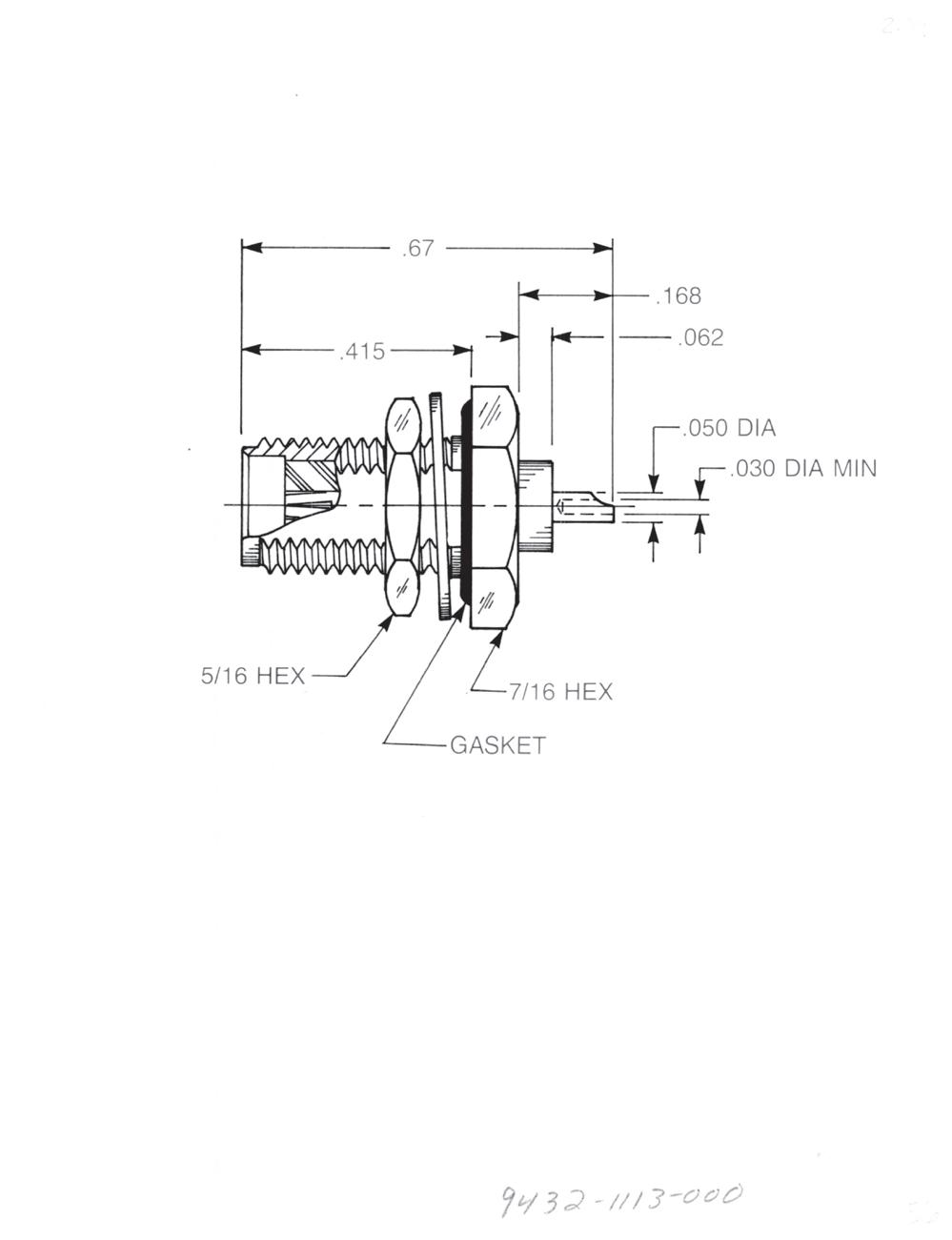
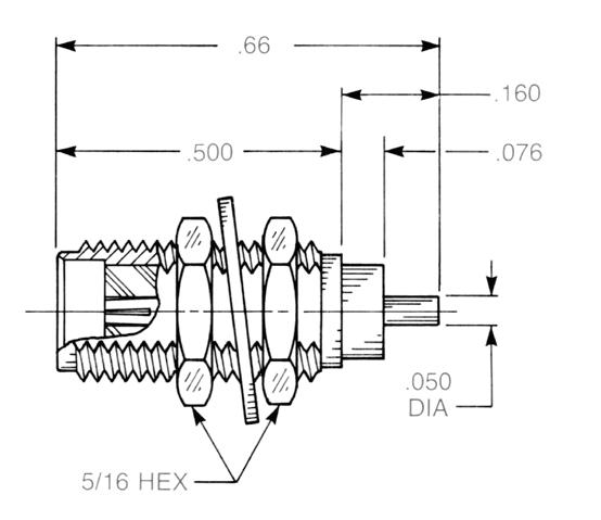
Straight Bulkhead Jack Receptacle
• Solder pot contact
• Rear mount
• With mounting gasket
Captive contact: 9432-1113-000 (Gold-plated) 9432-9113-000 (Passivated)
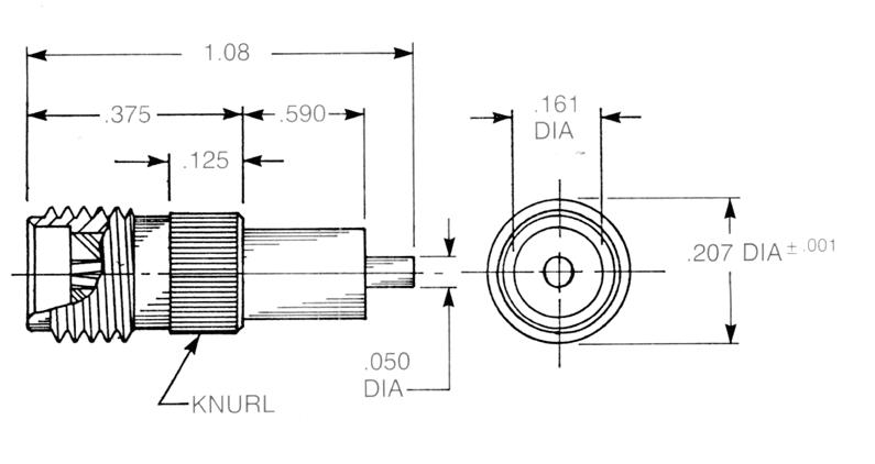
Straight Bulkhead Jack Receptacle
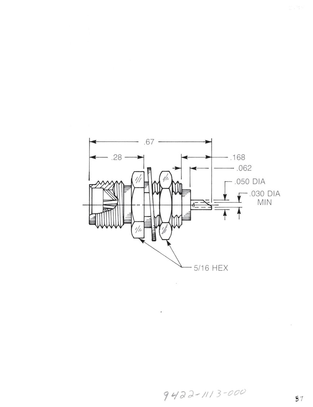
• Solder pot contact
• Front mount
Captive contact: 9422-1113-000 (Gold-plated) 9422-9113-000 (Passivated)
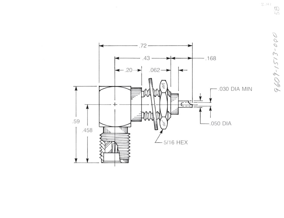
Right Angle Bulkhead Jack Receptacle
• Solder pot contact
• Front mount
Captive contact: 9609-1513-000 (Gold-plated) 9609-9513-000 (Passivated)
Additional contact and insulator configurations available upon request. Designed for use with 0.125˝ thick max panel.
2-28 Go online for data sheets and assembly instructions. Visit www.radiall.com/AEP and enter the part number.
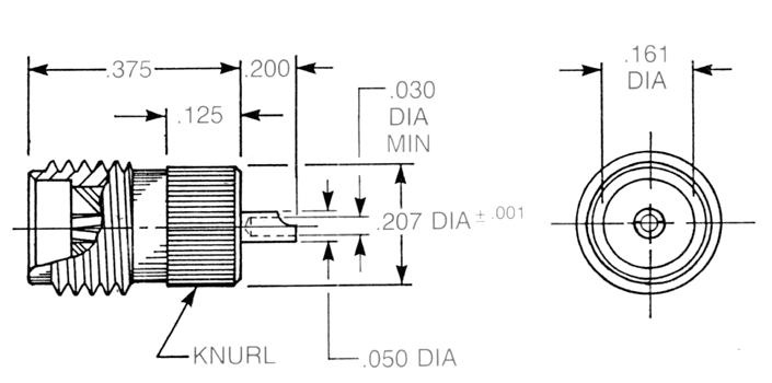
Bulkhead Jack Receptacles
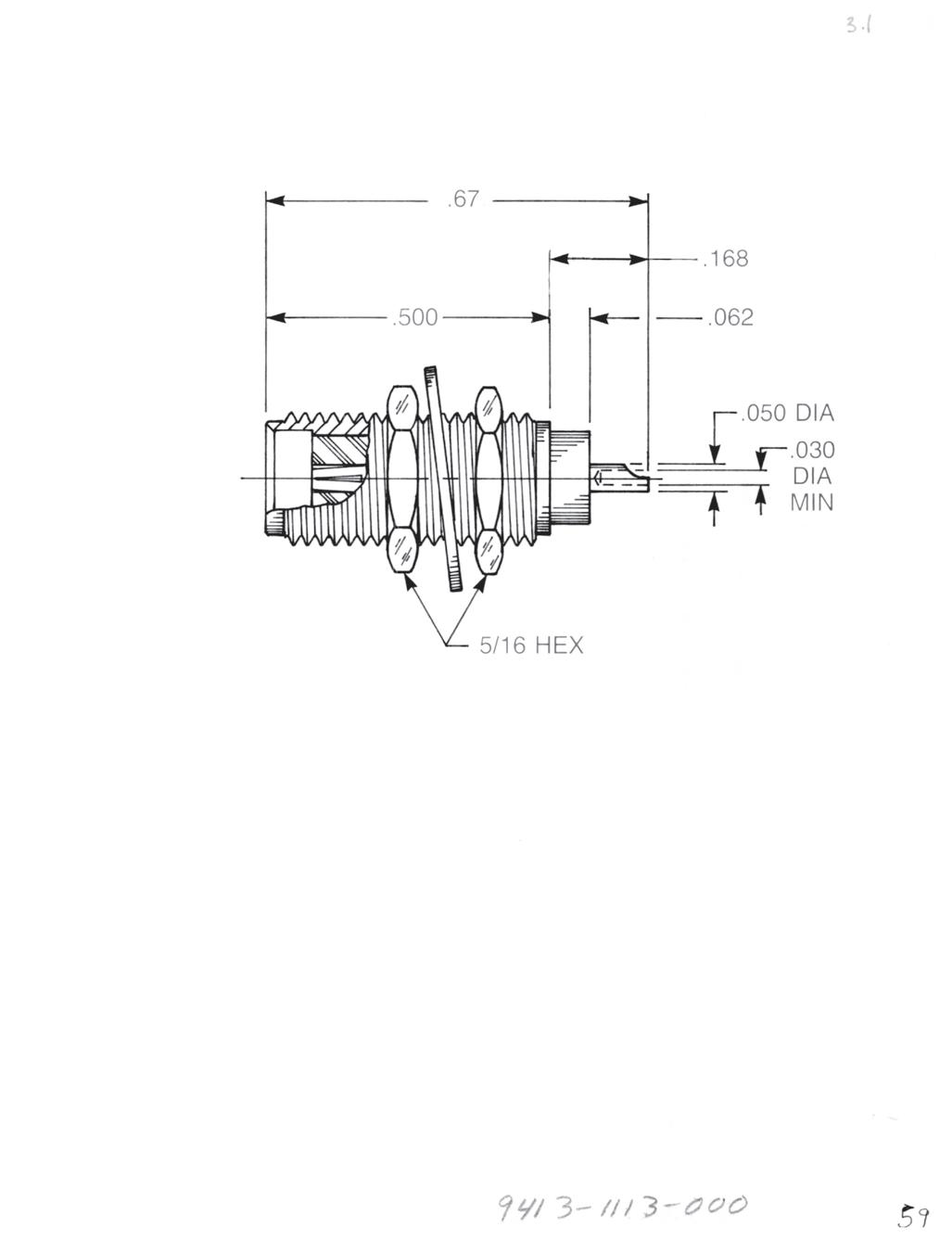
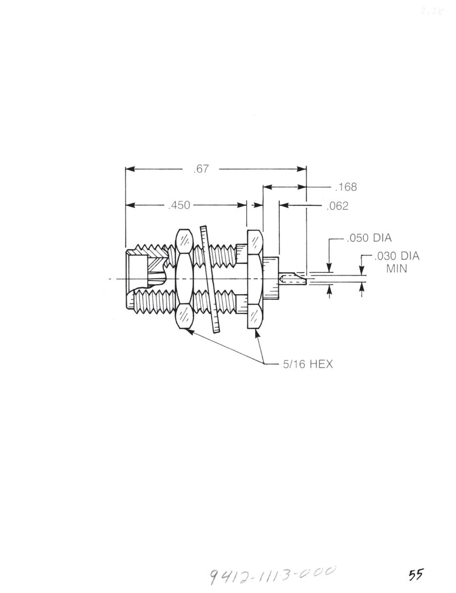
Straight Bulkhead Jack Receptacle
• Solder pot contact
• Round body
• Provided with two mounting nuts and one lockwasher
Captive contact:
9413-1113-000 (Gold-plated) 9413-9113-000 (Passivated)
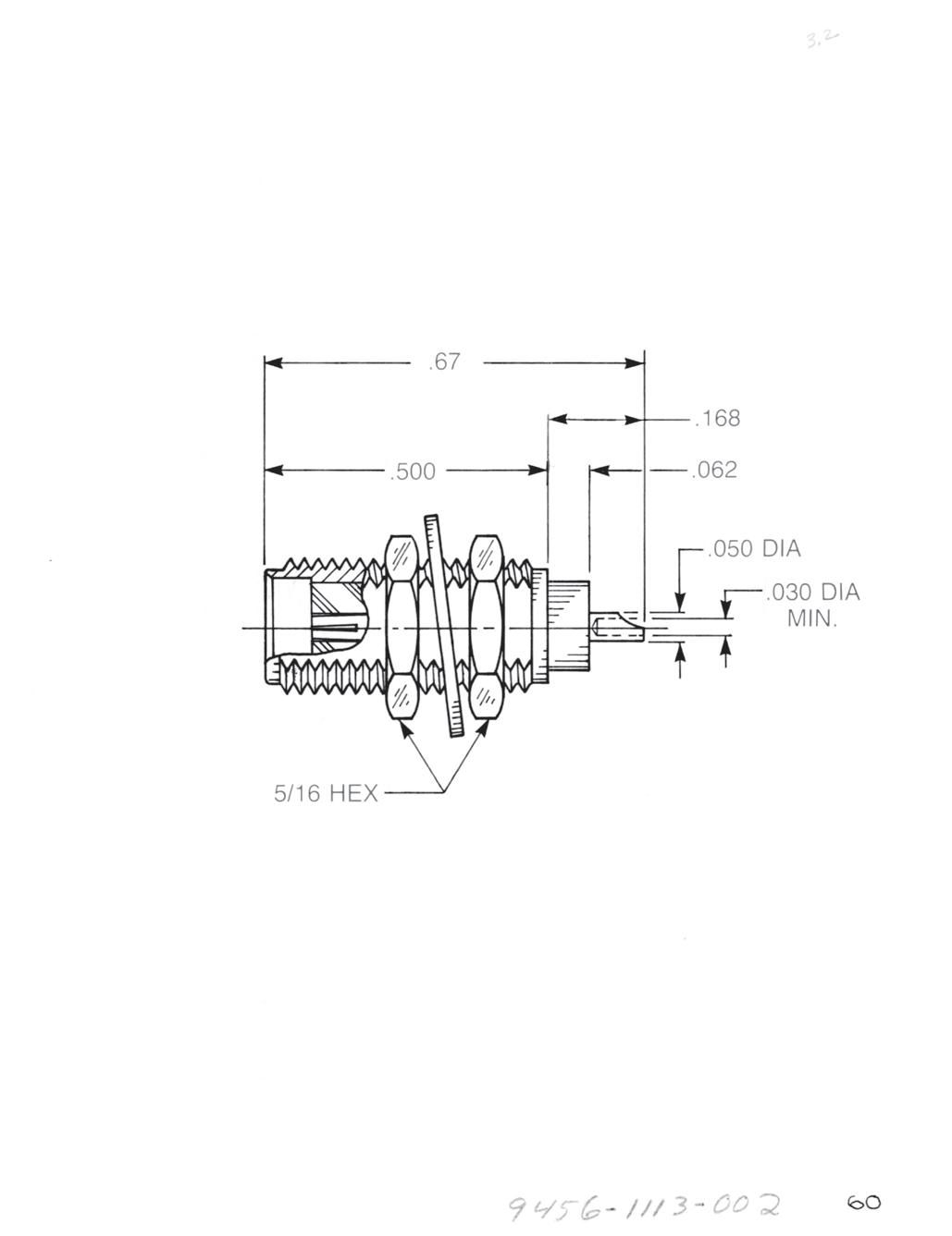
Straight Bulkhead Jack Receptacle
• Solder pot contact
• D-flatted body
• Provided with two mounting nuts and one lockwasher
Captive contact:
9456-1113-002 (Gold-plated) 9456-9113-002 (Passivated)
Straight Bulkhead Jack Receptacle
• Post contact
• Round body
• Provided with two mounting nuts and one lockwasher
Captive contact:
9013-1113-000 (Gold-plated) 9013-9113-000 (Passivated)
Straight Bulkhead Jack Receptacle
• Post contact
• D-flatted body
• Provided with two mounting nuts and one lockwasher
Captive contact:
9056-1113-000 (Gold-plated)
9056-9113-000 (Passivated)
Additional contact and insulator configurations available upon request. Designed for use with .125˝ thick max panel.
2-29
Simplification
Go online for data sheets and assembly instructions. Visit www.radiall.com/AEP and enter the part number.
SMA
is Our Innovation.
SMA
These knurl mount connectors can provide an economical alternative to flange mounted connectors and are especially useful in dense packaging applications.
To ensure retention, these connectors should be used in panels of 0.100˝ minimum thickness. Gold-plated bodies can be soldered to the panel if necessary, but an absolute minimum of heat should be used to prevent insulator damage.
Straight Jack Receptacle
• Extended contact and insulator
Captive contact:
9033-1113-000 (Gold-plated) 9033-9113-000 (Passivated)
Non-captive contact: 9033-1213-000 (Gold-plated) 9033-9213-000 (Passivated)
Straight Jack Receptacle
• Solder pot contact
Captive contact: 9433-1113-000 (Gold-plated) 9433-9113-000 (Passivated)
Straight Jack Receptacle
• Tab contact
Captive contact: 9133-1113-000 (Gold-plated) 9133-9113-000 (Passivated)
Non-captive contact: 9133-1213-000 (Gold-plated) 9133-9213-000 (Passivated)
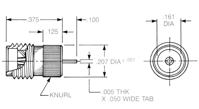
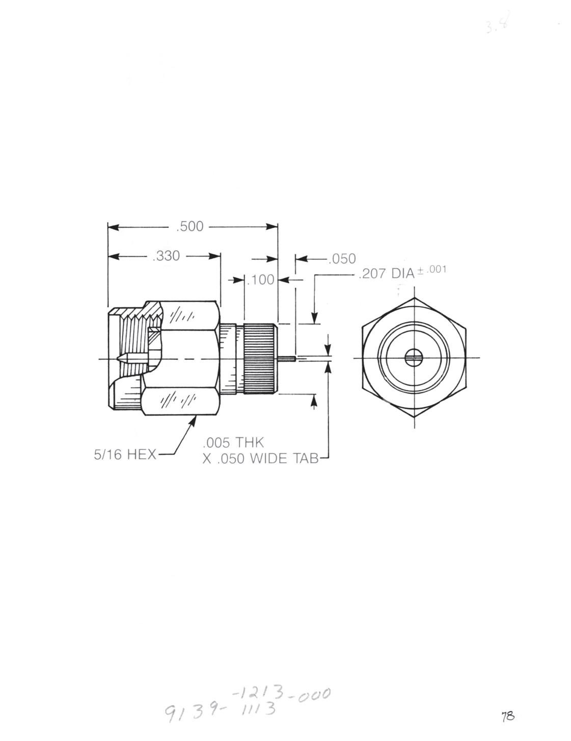
Straight Plug Receptacle
• Tab Contact
Captive contact: 9139-1113-000 (Gold-plated) 9139-9113-000 (Passivated)
Non-captive contact: 9139-1213-000 (Gold-plated) 9139-9213-000 (Passivated)
Additional contact and insulator configurations available upon request.
2-30
Visit www.radiall.com/AEP and enter the part number.
Knurl Mount
PCB Receptacles
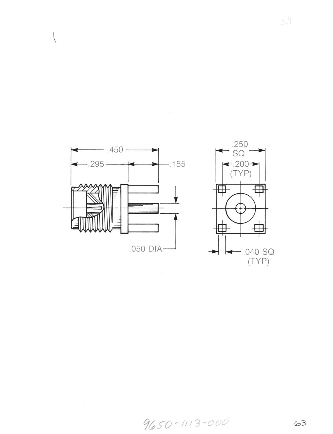
Straight Jack Receptacle
9650-1113-000 (Gold-plated)
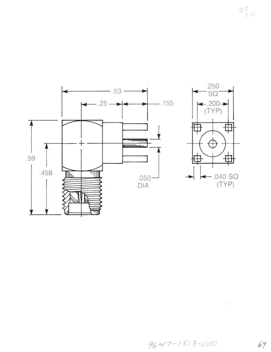
Right Angle Jack Receptacle
9647-1513-000 (Gold-plated)
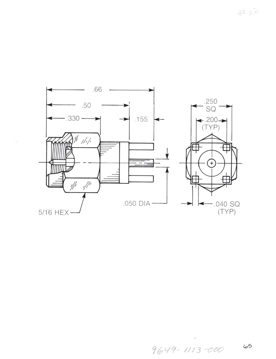
Straight Plug Receptacle
9649-1113-000 (Gold-plated)
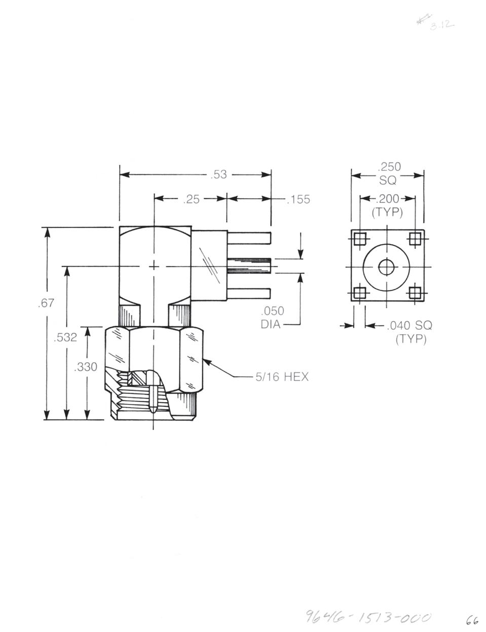
Right Angle Plug Receptacle
9646-1513-000 (Gold-plated)
2-31
Simplification
Go online for data sheets and assembly instructions. Visit www.radiall.com/AEP and enter the part number.
SMA
is Our Innovation.
SMA
Stripline Receptacles
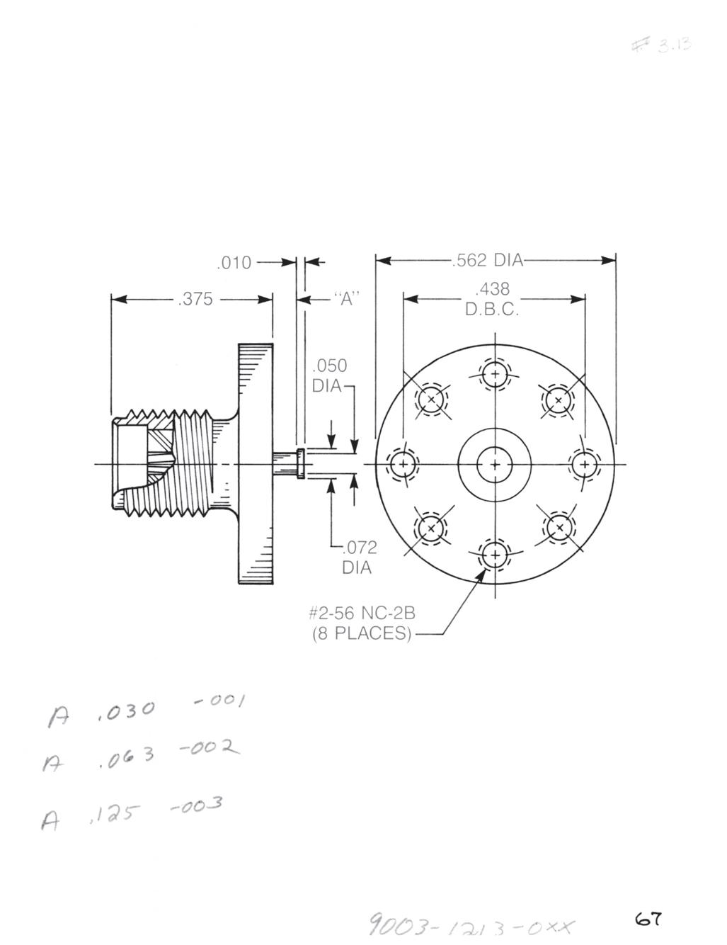
Straight Surface Mount Jack Receptacle
• Standard flange
• Non-captive contact
Dim. A
0.031 9003-1213-001 (Gold-plated)
9003-9213-001 (Passivated)
0.063 9003-1213-002 (Gold-plated)
9003-9213-002 (Passivated)
0.125 9003-1213-003 (Gold-plated)
9003-9213-003 (Passivated)
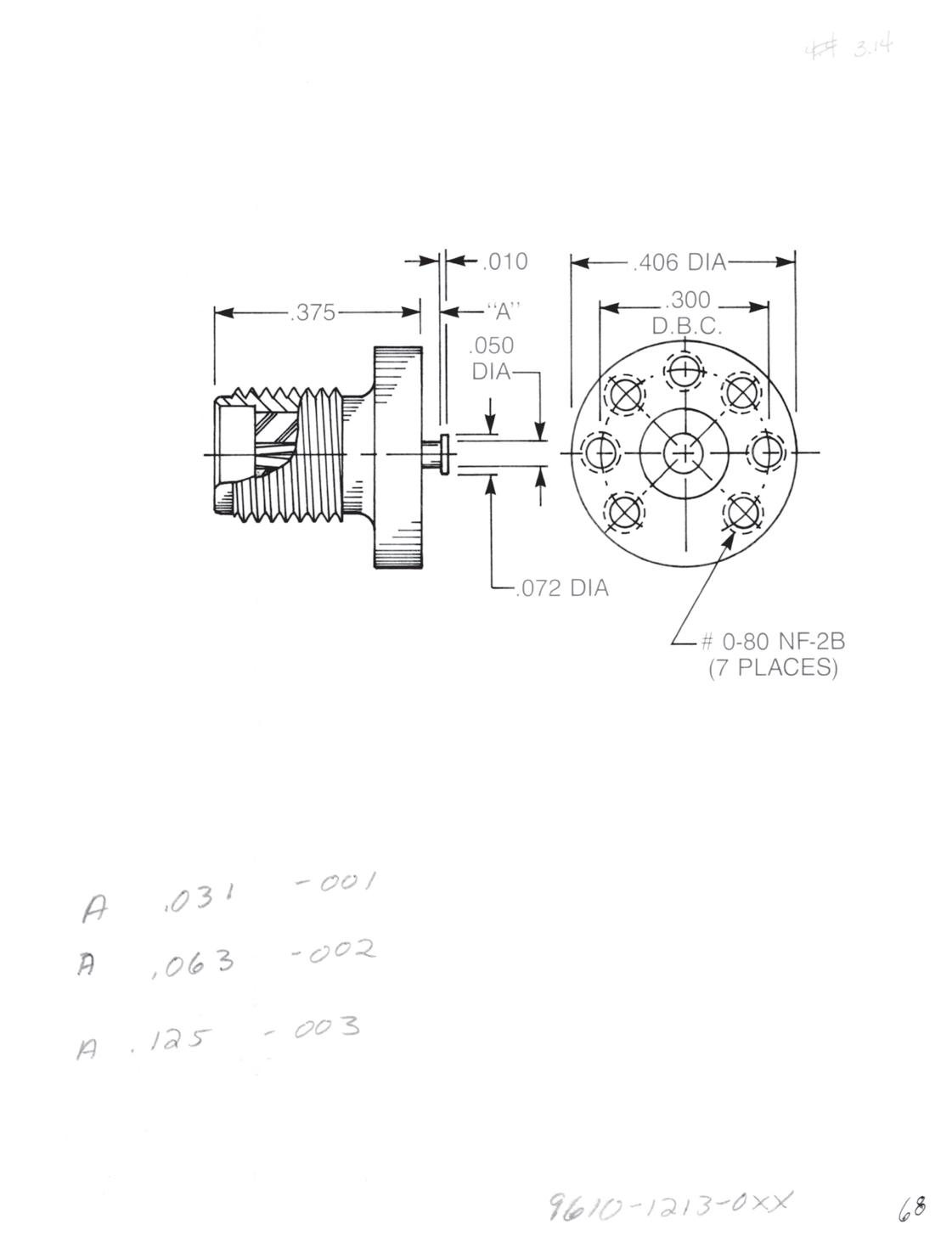
Straight Surface Mount Jack Receptacle
• Small diameter flange
• Non-captive contact
Dim. A
0.031 9610-1213-001 (Gold-plated)
9610-9213-001 (Passivated)
0.063 9610-1213-002 (Gold-plated)
9610-9213-002 (Passivated)
0.125 9610-1213-003 (Gold-plated)
9610-9213-003 (Passivated)
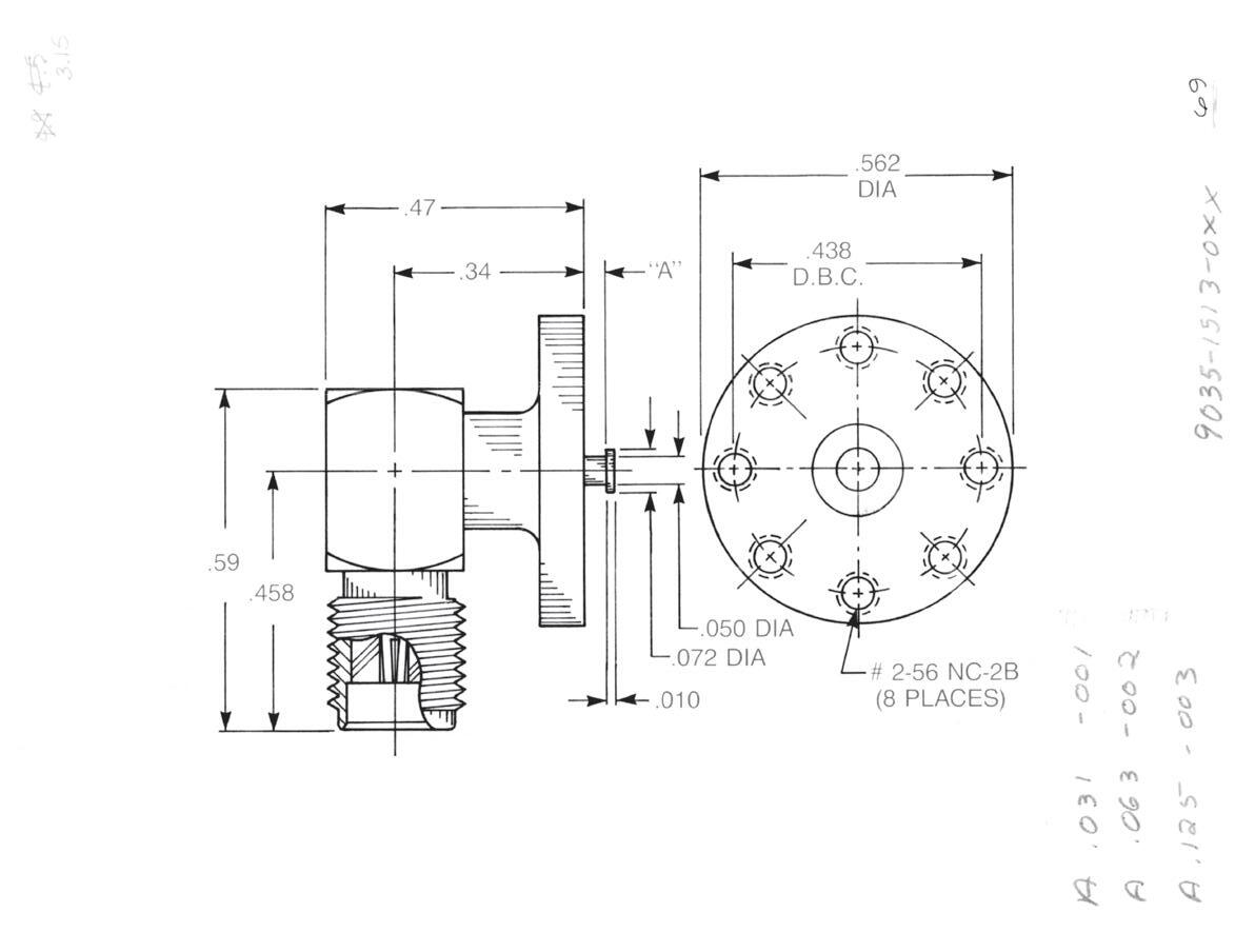
Right Angle Surface Mount Jack Receptacle
• Standard flange
• Non-captive contact
Dim. A
0.031 9035-1513-001 (Gold-plated)
9035-9513-001 (Passivated)
0.063 9035-1513-002 (Gold-plated)
9035-9513-002 (Passivated)
0.125 9035-1513-003 (Gold-plated)
9035-9513-003 (Passivated)
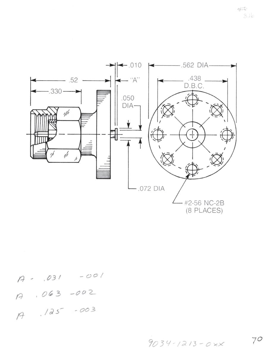
Straight Surface Mount Plug Receptacle
• Standard flange
• Non-captive rear contact
Dim. A
0.031 9034-1213-001 (Gold-plated)
9034-9213-001 (Passivated)
0.063 9034-1213-002 (Gold-plated)
9034-9213-002 (Passivated)
0.125 9034-1213-003 (Gold-plated)
9034-9213-003 (Passivated)
Connectors for use with other board thicknesses are available.
2-32
Visit www.radiall.com/AEP and enter the part number.
Hermetic Seal Launchers
AEP SMA hermetic seal launchers are designed for use with separate hermetic seals with pin diameters ranging from 0.012˝ to 0.036˝. The use of a connector/seal system rather than a connector with an integral seal means that microstrip boxes can remain sealed when connectors are removed or changed. The connectors can be reused many times on components that need to be “connectorized” only for testing.
All the items in this section have passivated bodies. All other characteristics are as shown on page 2-3 for SMA series connectors.
The electrical performance of these launchers is dependent to a great extent upon the method used to affix the inner seal pin to the microstrip line. The application notes on pages 2-34 to 2-40 give a detailed explanation of the connectors' electrical characteristics.
We also have a wide variety of hermetic seals available in configurations other than those shown here. For more information, please contact us directly.
2-33
Simplification
Go online for data sheets and assembly instructions. Visit www.radiall.com/AEP and enter the part number.
SMA
is Our Innovation.
Hermetic Seal Launchers
APPLICATION NOTES
INTRODUCTION
In recent years, as hermetically sealed MIC (Microwave Integrated Circuit) devices have come into common usage, designers have sought an alternative to “spark plug” type SMA connectors for launching from microstrip to a coaxial line. “Spark plug” launchers perform well electrically and mechanically, but they have some disadvantages: Because the hermetic seal is integral to the connector, the package loses hermeticity if the connector is removed. They are also expensive to manufacture, requiring costly special welding and testing equipment, and manufacturing yields can be quite low.
The alternative approach discussed here is to seal the package with an inexpensive 50 ohm hermetic seal and use a non-hermetic SMA connector that fits over the protruding seal pin. There are several advantages to this method: If the seal is damaged during installation, it can be replaced easily and inexpensively. If a connector is damaged during service, it can be replaced without compromising the package’s hermeticity. If devices are to be shipped with pins only, a connector can be put on for testing, removed and reused for testing on other packages.
This type of connector is known by many names as no industry-wide generic term has come into use. It may be variously described as a hermetic seal launcher, MIC launcher, field replaceable jack or various combinations of these terms.
All of these terms are descriptions of the same thing: SMA series receptacles designed for mounting on a hermetic seal which provides an environmental, mechanical and electrical transition from a microstrip line to a coaxial line. They typically have flanges for mounting to the package; screw-in types are available but require a thick-walled package to allow for seal mounting.
DESIGN
AEP SMA hermetic seal launchers are designed with mechanically captivated contacts and insulators. Epoxy captivation is avoided in order to eliminate RF leakage through epoxy fill holes at high frequencies.
50 ohm hermetic seals with pin diameters of 0.012˝, 0.015˝ and 0.018˝ use glass dielectrics that yield an outer ring diameter considerably smaller than the inner diameter of a standard SMA body. In order to make the transition from an SMA interface to this smaller diameter, the diameters of the connector body, contact and insulator must be stepped down from the front (SMA interface) end of the connector to the rear (seal interface) end.
These steps, together with the barbs and shoulders used to captivate the contact and insulator, are designed and located to perform electrical compensation for locally capacitive or inductive sections. The seal’s electrical characteristics and the impedance at the connector/seal interface are also compensated for, in order to produce a connector and seal combination as close to 50 ohm overall as possible. Figure A illustrates the transitional steps and contact captivation method.
2-34
Go online for data sheets and assembly instructions. Visit www.radiall.com/AEP and enter the part number.
SMA

APPLICATION NOTES
Hermetic Seal Launchers
APPLICATION NOTES
THE COAXIAL LINE TO MICROSTRIP INTERFACE
Although the impedance of the connectors and seals can be tightly controlled at the point of manufacture, their performance in a system will be greatly affected by the method and process of attaching the seal pin to the microstrip line. It is very important for any discontinuities introduced by the pin attachment to be minimized and “tweaked” as much as possible to get the maximum electrical performance from the connector and seal.
The first step toward the best match is to select a seal with a pin diameter as close as possible to the microstrip line width. If the coaxial section (pin) is significantly larger than the microstrip section (line), the circuit will show an inductive discontinuity as the input signal radiates farther on the pin before entering the line (antenna effect). Conversely, if the line section is significantly larger than the pin, the circuit will become capacitive in this section.
Perhaps the most important part of the entire connector/seal/microstrip assembly is the pin-to-line attachment method and process. Please note that as connector manufacturers rather than microstrip circuit designers, we cannot recommend any specific method of pin attachment. The information shown here has been compiled from discussions with our customers. The method used in a given situation will depend on the specific design and operating requirements of the device, and the equipment available to the circuit manufacturer. As with any electronic device, tradeoffs are commonly required to balance the need for performance over a narrow or wide frequency bandwidth and environmental and mechanical considerations.
When a microstrip device is subjected to a wide temperature range during service, a circumstance frequently arises which adds yet another consideration to the decision on the pin attachment method. If the thermal expansion coefficient of the package material is different from that of the substrate, relative movement between the pin and the line will occur during temperature changes. With widely different expansion rates and/or wide temperature ranges, this movement can be enough to break a direct pin-to-line bond. In these cases, an attachment incorporating a sliding contact or a looped gold ribbon is commonly used to permit movement of the line relative to the pin. Keep in mind that most methods used to allow this movement will add discontinuities greater than those from a direct bond.
Whichever method is used for the pin attachment, a prototype unit should be examined with a fast risetime TDR to determine if the attachment section is inductive or capacitive. An appropriate amount of capacitance or inductance should be added to the circuit to compensate for the discontinuities found.
2-36
Go online for data sheets and assembly instructions. Visit www.radiall.com/AEP and enter the part number.
SMA

2-37
Go online for data sheets and assembly instructions. Visit www.radiall.com/AEP and enter the part number.
SMA
Hermetic
Seal Launchers APPLICATION NOTES
Hermetic

Some users report that using a seal with the circuit-end of the seal pin flattened gives them better results
Visit www.radiall.com/AEP and enter the part number.
A (Pin
B (± 0.005) (Flat Length)* C (± 0.005) (Flat Width) D (± 0.002) (Flat Thickness) 0.012 0.050 0.025 0.006 0.015 0.050 0.030 0.007 0.018 0.050 0.035 0.009 0.020 0.050 0.040 0.010
ø)
Seal Launchers APPLICATION NOTES

APPLICATION NOTES
We have tested our connectors by several methods and have found significant drawbacks in all except
Testing on a “dummy” microstrip package (direct line from input to output) most closely simulates the final application of the connectors and seals. However, the test results will be skewed by the pin attachment method and will be valid for production units only if the attachment method in production
Testing two connectors bolted back-to-back with a pin joining the center contacts is inaccurate because it does not include the seal with which the connectors are designed to be used. This test method can also be inconsistent because of the difficulty of making sure the connectors are lined up with each other
compensation designed into the connector for the seal. One user who tests by this method found that the brand of connectors rated worst by the test fixture actually worked the best when installed on one
The test method used to obtain the information in Figure E is to mount two connectors back-to-back on a fixture that has the appropriate seal installed (See Figure D). The thickness of the fixture (a brass plate) is such that the seal surfaces are flush with the fixture surface, as they should be with the MIC
2-39
Simplification is Our Innovation. Visit www.radiall.com/AEP and enter the part number.
SMA
Hermetic
Seal Launchers

APPLICATION NOTES
2-40
Go online for data sheets and assembly instructions. Visit www.radiall.com/AEP and enter the part number.
SMA
Hermetic Seal Launchers

Pin ø "D” Air Dielectric "D” Teflon Dielectric 0.012 0.028 0.040 0.015 0 .035 0.050 0.018 0.041 0.059 0.020 0.046 0.066
Hermetic Seal Launchers
SMA
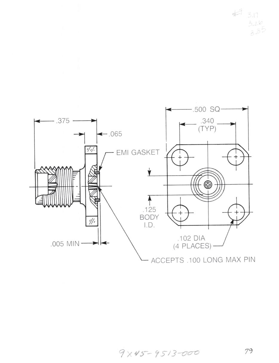
Hermetic Seal Launchers for 0.012˝ Diameter Pins
Straight Jack
• ½˝ Square flange
9045-9513-000
Optional packaging: 9145-9513-000 (Includes 920-55)
9245-9513-000 (Includes 920-55 and 907-111-1)
9345-9513-000 (Includes 907-111-1)
Straight Jack
• 2-hole flange
9044-9513-000
Optional packaging: 9144-9513-000 (Includes 920-55)
9244-9513-000 (Includes 920-55 and 907-111-1)
9344-9513-000 (Includes 907-111-1)
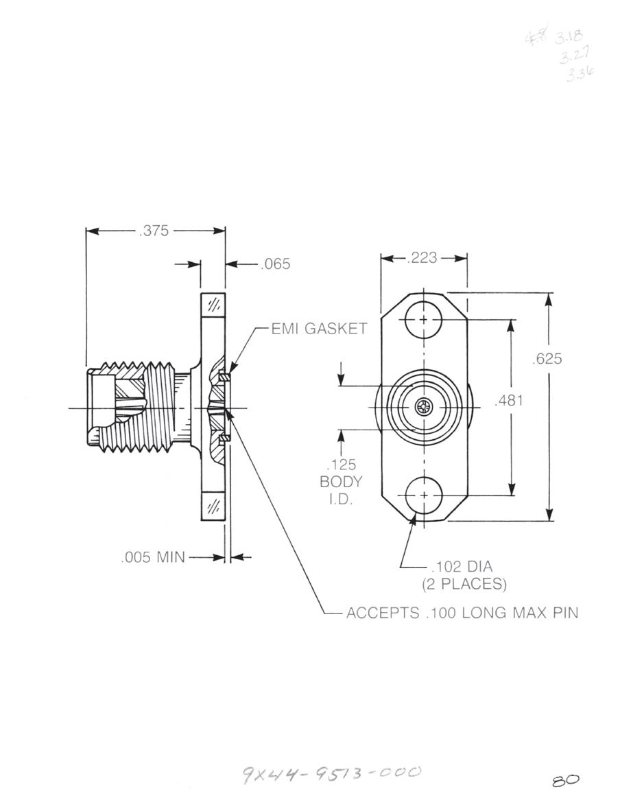
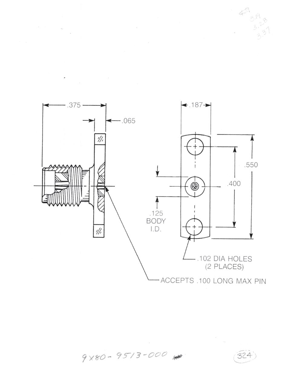
Straight Jack Narrow
• 2-hole flange
• No EMI gasket
9080-9513-000
Optional packaging: 9180-9513-000 (Includes 920-55)
9280-9513-000 (Includes 920-55 and 907-111-1)
9380-9513-000 (Includes 907-111-1)
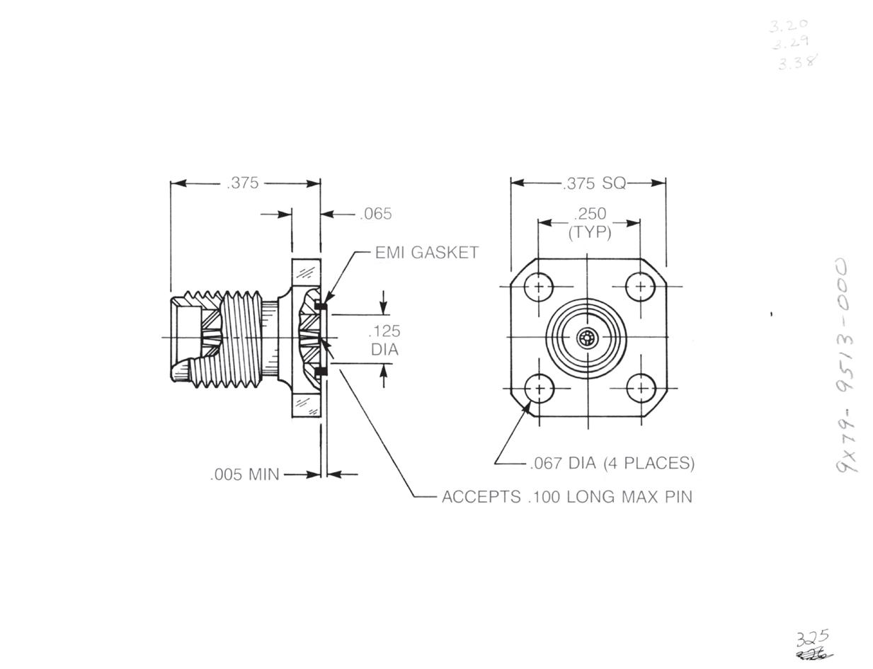
Straight Jack
• ³⁄8˝ Square flange
9079-9513-000
Optional packaging:
9179-9513-000 (Includes 920-55)
9279-9513-000 (Includes 920-55 and 907-111-1)
9379-9513-000 (Includes 907-111-1)
These parts accept pin diameters from 0.011˝ to 0.015˝.
2-42
Go online for data sheets and assembly instructions. Visit www.radiall.com/AEP and enter the part number.
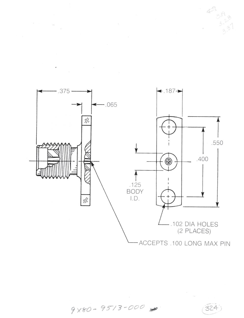
Hermetic Seal Launchers for 0.012˝ Diameter Pins


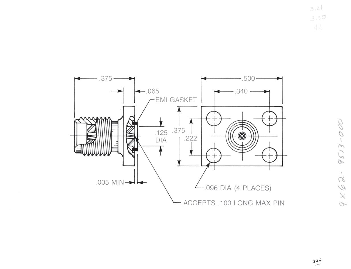
Straight Jack
• Rectangular flange
9062-9513-000
Optional packaging:
9162-9513-000 (Includes 920-55)
9262-9513-000 (Includes 920-55 and 907-111-1)
9362-9513-000 (Includes 907-111-1)
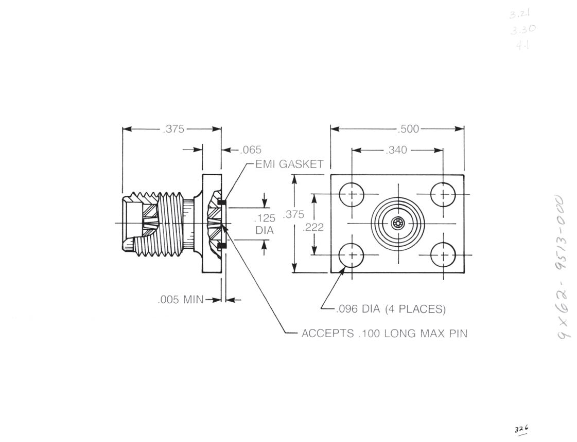
Straight Plug
• ½˝ Square flange
9047-9513-000
Optional packaging:
9147-9513-000 (Includes 920-55)
9247-9513-000 (Includes 920-55 and 907-111-1)
9347-9513-000 (Includes 907-111-1)
Straight Plug
• 2-hole flange
9046-9513-000
Optional packaging: (Includes 920-55 and 907-111-1)
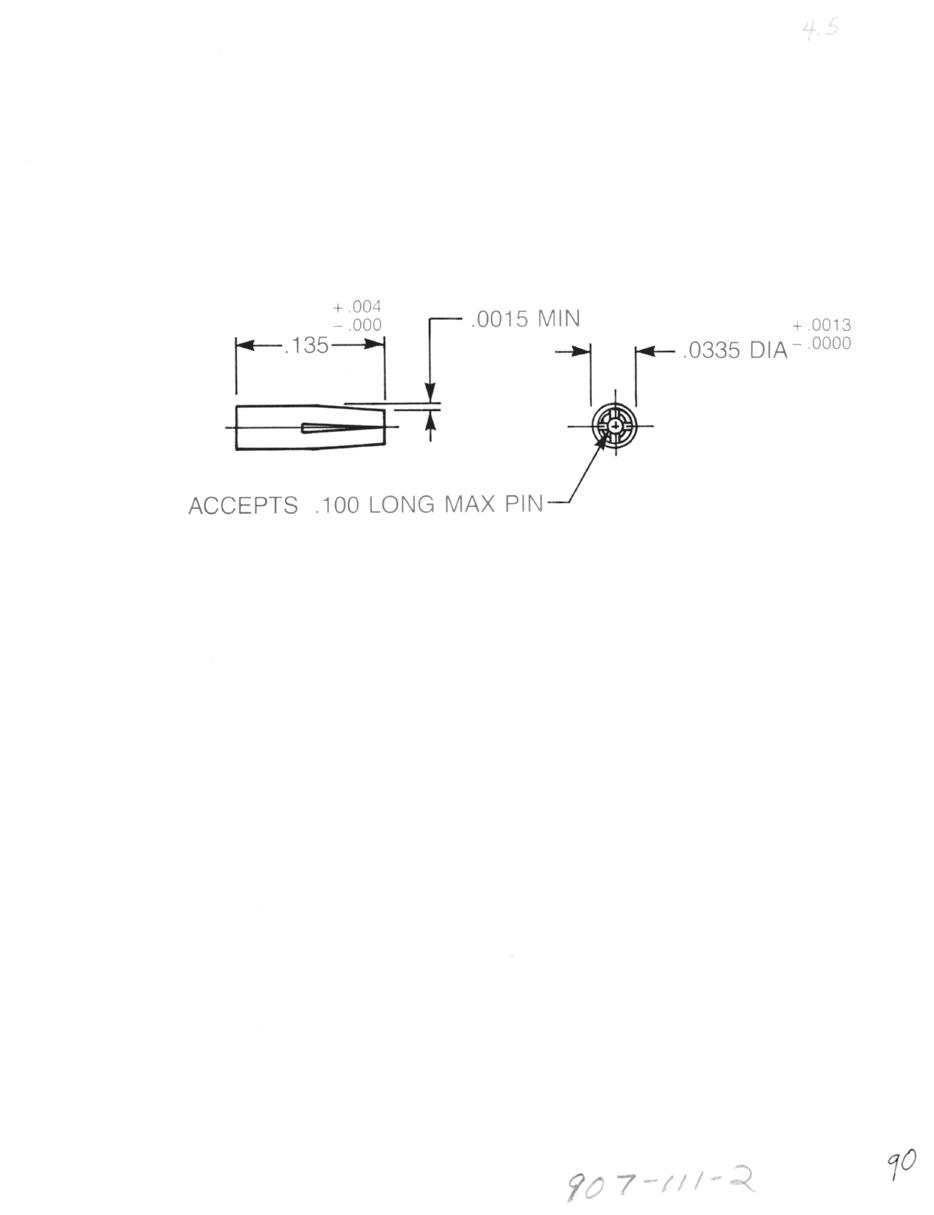
Accessory Contact
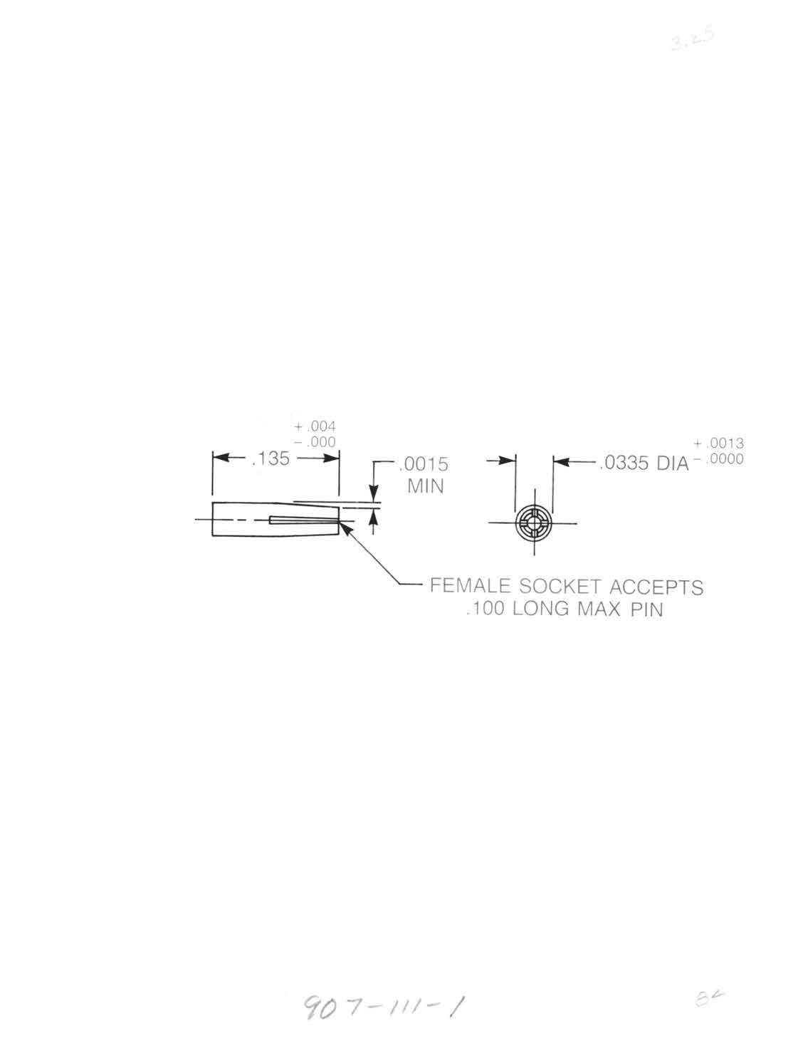
P/N 907-111-1
Material: Beryllium copper
Finish: Gold per MIL-G-45204, type II, class I, grade C, over 0.0001 copper per MIL-C-14550
These parts accept pin diameters from 0.011˝ to 0.015˝.
2-43
Simplification
Go online for data sheets and assembly instructions. Visit www.radiall.com/AEP and enter the part number.
SMA
is Our Innovation.
Hermetic Seal Launchers for 0.015˝ Diameter Pins
Straight Jack
• ½˝ Square flange
9045-9513-001
Optional packaging:
9145-9513-001 (Includes 920-82)

9245-9513-001 (Includes 920-82 and 907-111-5)
9345-9513-001 (Includes 907-111-5)
Straight Jack
• 2-hole flange
9044-9513-001
Optional packaging:
9144-9513-001 (Includes 920-82)
9244-9513-001 (Includes 920-82 and 907-111-5)
9344-9513-001 (Includes 907-111-5)
Straight Jack Narrow
• 2-hole flange
• No EMI gasket
9080-9513-001
Optional packaging:
9180-9513-001 (Includes 920-82)
9280-9513-001 (Includes 920-82 and 907-111-5)
9380-9513-001 (Includes 907-111-5)
Straight Jack
• ³⁄8˝ Square flange
9079-9513-001
Optional packaging:
9179-9513-001 (Includes 920-82)
9279-9513-001 (Includes 920-82 and 907-111-5)
9379-9513-001 (Includes 907-111-5)
These parts accept pin diameters from 0.014˝ to 0.016˝.
2-44
Go online for data sheets and assembly instructions. Visit www.radiall.com/AEP and enter the part number.
SMA
Hermetic Seal Launchers for 0.015˝ Diameter Pins

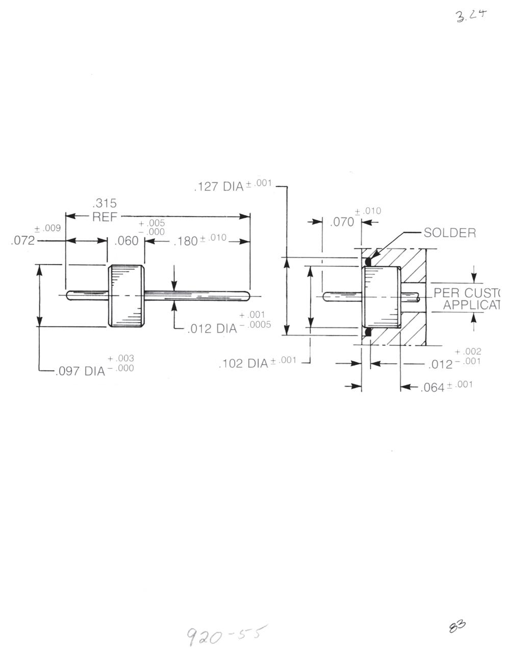
Solder-In Hermetic Seal P/N 920-82
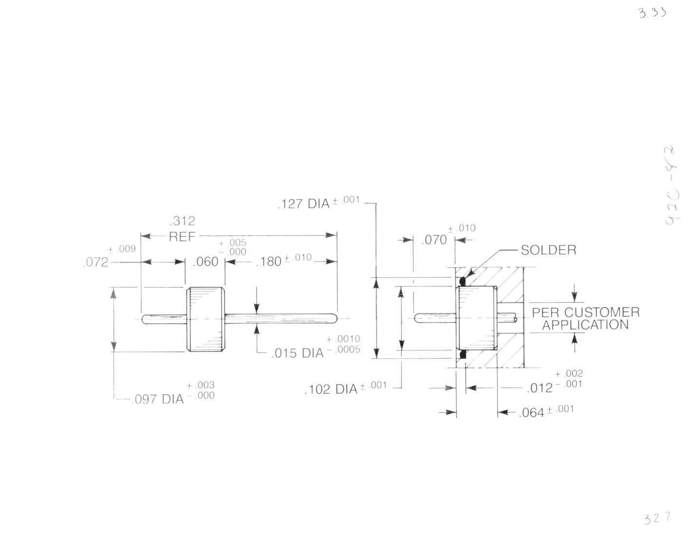
See page 2-41 for material and finish specifications and mounting dimensions.
Straight Jack
• Rectangular flange
9062-9513-001
Optional packaging: 9162-9513-001 (Includes 920-82)
9262-9513-001 (Includes 920-82 and 907-111-5)
9362-9513-001 (Includes 907-111-5)
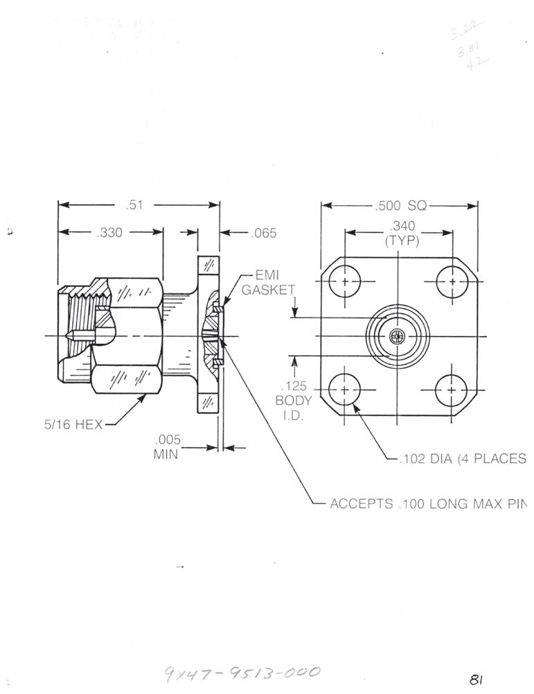
Straight Plug • ½˝ Square flange
9047-9513-001
Optional packaging:
9147-9513-001 (Includes 920-82)
9247-9513-001 (Includes 920-82 and 907-111-5)
9347-9513-001 (Includes 907-111-5)
Straight Plug • 2-hole flange
9046-9513-001
Optional packaging: (Includes 920-82 and 907-111-5)
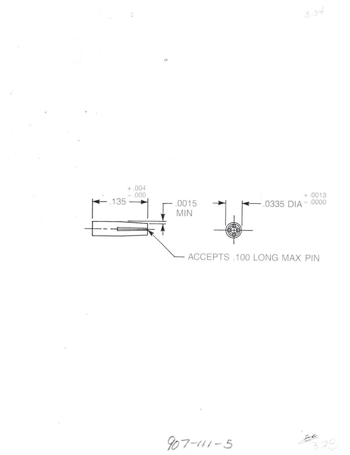
Accessory Contact P/N 907-111-5
Material: Beryllium copper
Finish: Gold per MIL-G-45204, type II, class I, grade C, over 0.0001 copper per MIL-C-14550
These parts accept pin diameters from 0.014˝ to 0.016˝.
2-45
Go online for data sheets and assembly instructions. Visit www.radiall.com/AEP and enter the part number.
SMA Simplification is Our Innovation.
SMA
Hermetic Seal Launchers for 0.018˝ Diameter Pins
Straight Jack
• ½˝ Square flange
9049-9513-000
Optional packaging:
9149-9513-000 (Includes 920-56)
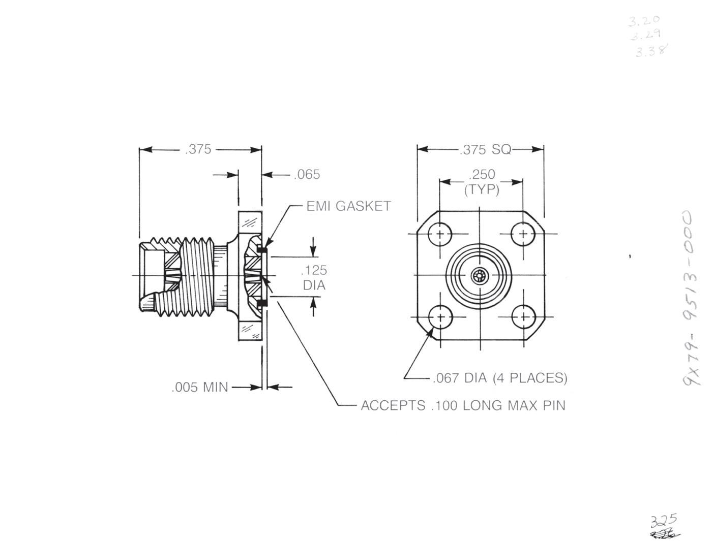
9249-9513-000 (Includes 920-56 and 907-111-2)
9349-9513-000 (Includes 907-111-2)
Straight Jack
• 2-hole flange
9048-9513-000
Optional packaging:
9148-9513-000 (Includes 920-56)
9248-9513-000 (Includes 920-56 and 907-111-2)
9348-9513-000 (Includes 907-111-2)
Straight Jack
• Narrow 2-hole flange
• No EMI gasket
9081-9513-000
Optional packaging:
9181-9513-000 (Includes 920-56)
9281-9513-000 (Includes 920-56 and 907-111-2)
9381-9513-000 (Includes 907-111-2)
Straight Jack
• ³⁄8˝ Square flange
9074-9513-000
Optional packaging:
9174-9513-000 (Includes 920-56)
9274-9513-000 (Includes 920-56 and 907-111-2)
9374-9513-000 (Includes 907-111-2)
These parts accept pin diameters from 0.016˝ to 0.020˝.
2-46
Go online for data sheets and assembly instructions. Visit www.radiall.com/AEP and enter the part number.
Seal Launchers for 0.018˝ Diameter Pins
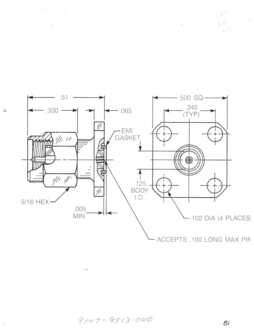
Straight Jack
• Rectangular flange
9068-9513-000
Optional packaging:
9168-9513-000 (Includes 920-56)
9268-9513-000 (Includes 920-56 and 907-111-2)
9368-9513-000 (Includes 907-111-2)
Straight Plug • ½˝ Square flange
9051-9513-000
Optional packaging:
9151-9513-000 (Includes 920-56)
9251-9513-000 (Includes 920-56 and 907-111-2)
9351-9513-000 (Includes 907-111-2)
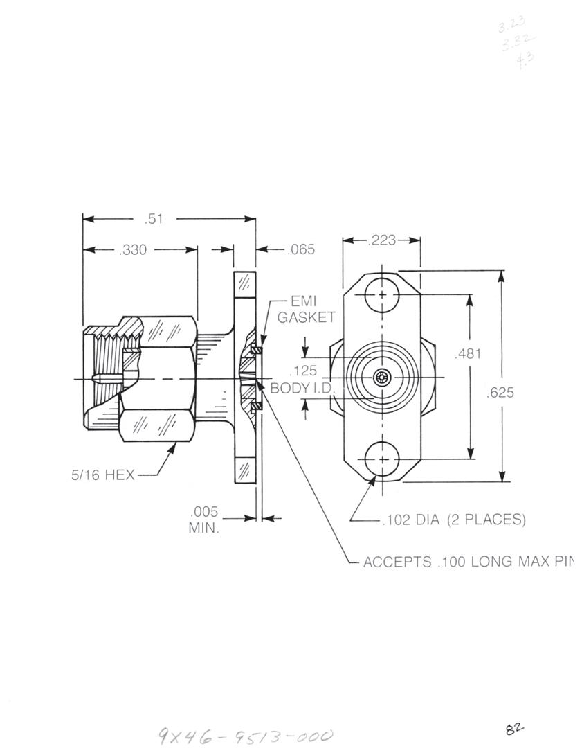
Straight Plug
• 2-hole flange
9050-9513-000
Optional packaging:
9150-9513-000 (Includes 920-56)
9250-9513-000 (Includes 920-56 and 907-111-2)
9350-9513-000 (Includes 907-111-2)
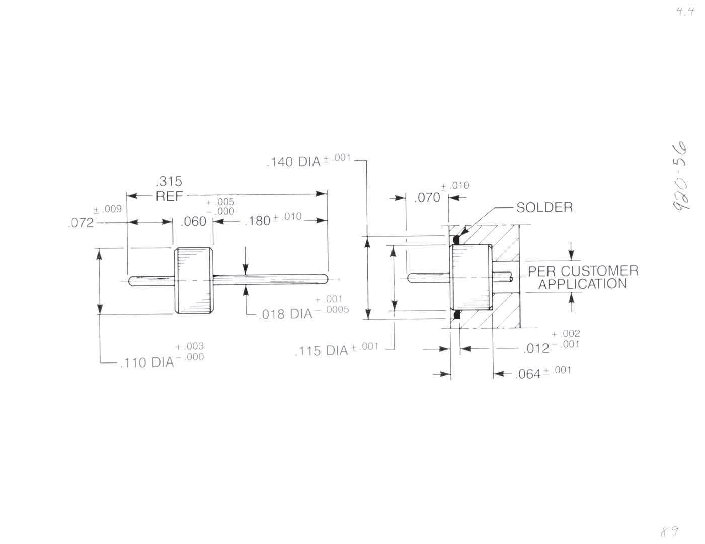
Accessory Contact
P/N 907-111-2
Material: Beryllium copper
Finish: Gold per MIL-G-45204 , type II, class I, grade C, over .0001 copper per MIL-C-14550
These parts accept pin diameters from 0.016˝ to 0.020˝.
2-47
Simplification
Go online for data sheets and assembly instructions. Visit www.radiall.com/AEP and enter the part number.
SMA
is Our Innovation.
Hermetic
SMA
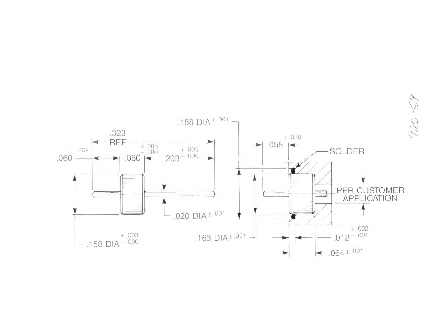
Hermetic Seal Launchers for 0.020˝ Diameter Pins
The hermetic seal launchers shown here are designed for use with seals having a 0.020˝ pin diameter and a 0.160� outer ring diameter. The contact and insulator diameters are constant through these connectors since they do not require the internal compensation featured in the launchers for smaller seals. The large outer diameter of the seals precludes the use of EMI gaskets on these connectors.
Straight Jack
• ½˝ Square flange
Optional packaging: 9504-9113-031
9504-9113-034 (Includes 920-69)
Straight Jack
• 2-hole flange
Optional packaging: 9508-9113-002
9508-9113-003 (Includes 920-69)
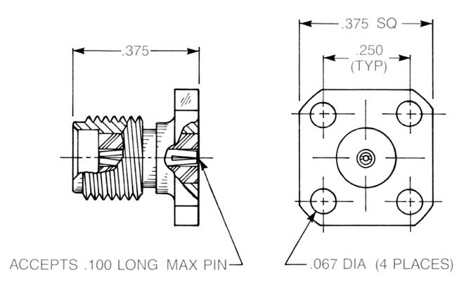
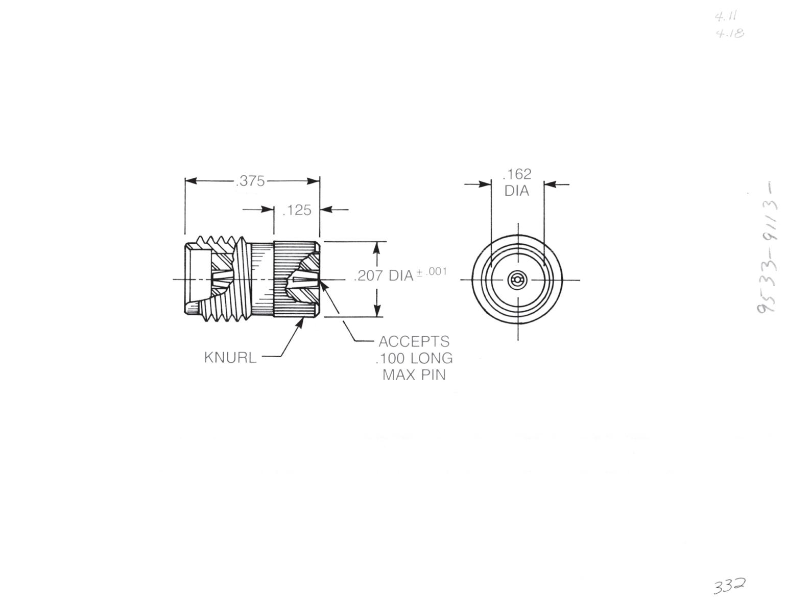
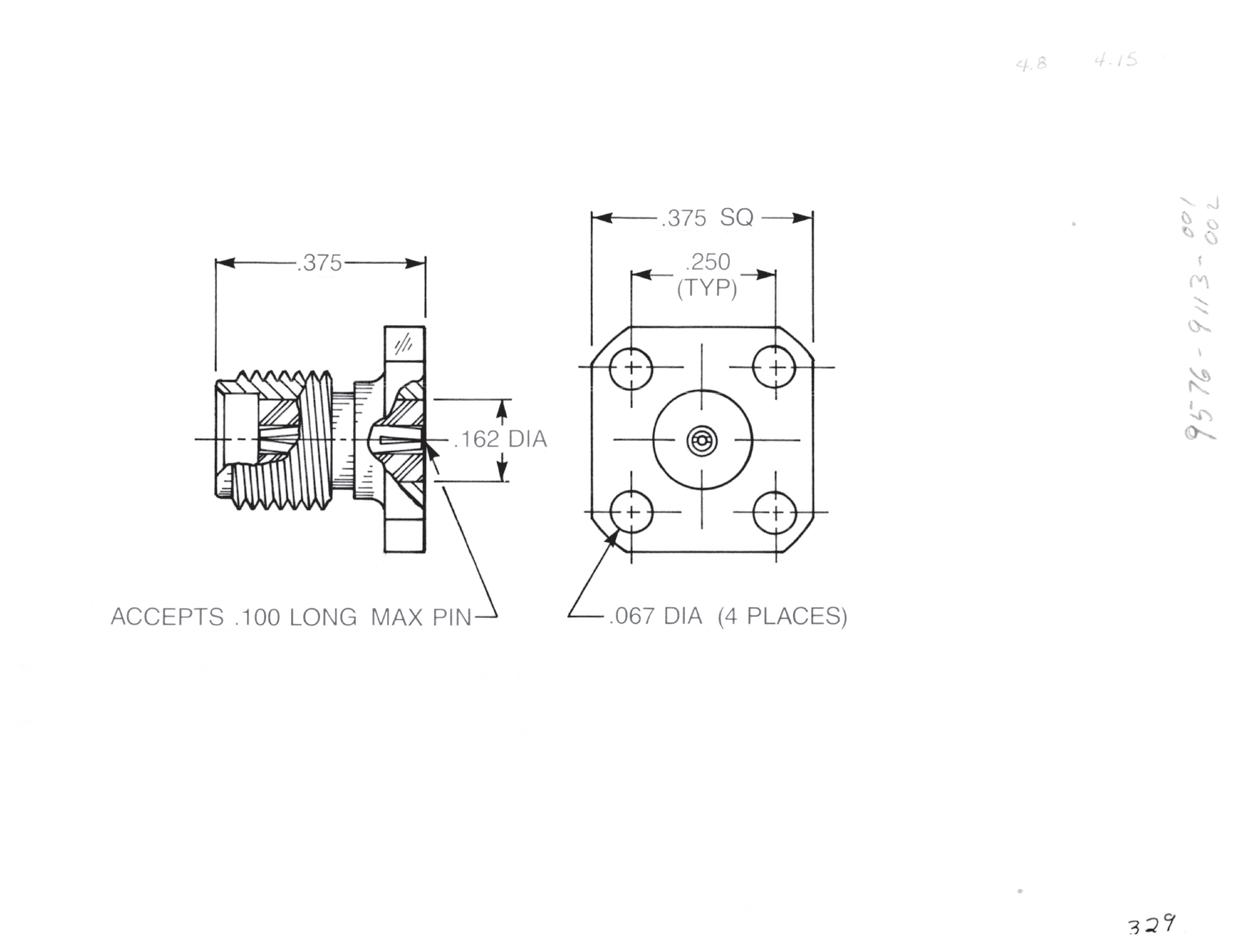
Straight Jack
• ³⁄8˝ Square flange
Optional packaging: 9576-9113-001
9576-9113-002 (Includes 920-69)
2-48
Go online for data sheets and assembly instructions. Visit www.radiall.com/AEP and enter the part number.
Hermetic Seal Launchers for 0.020˝ Diameter Pins
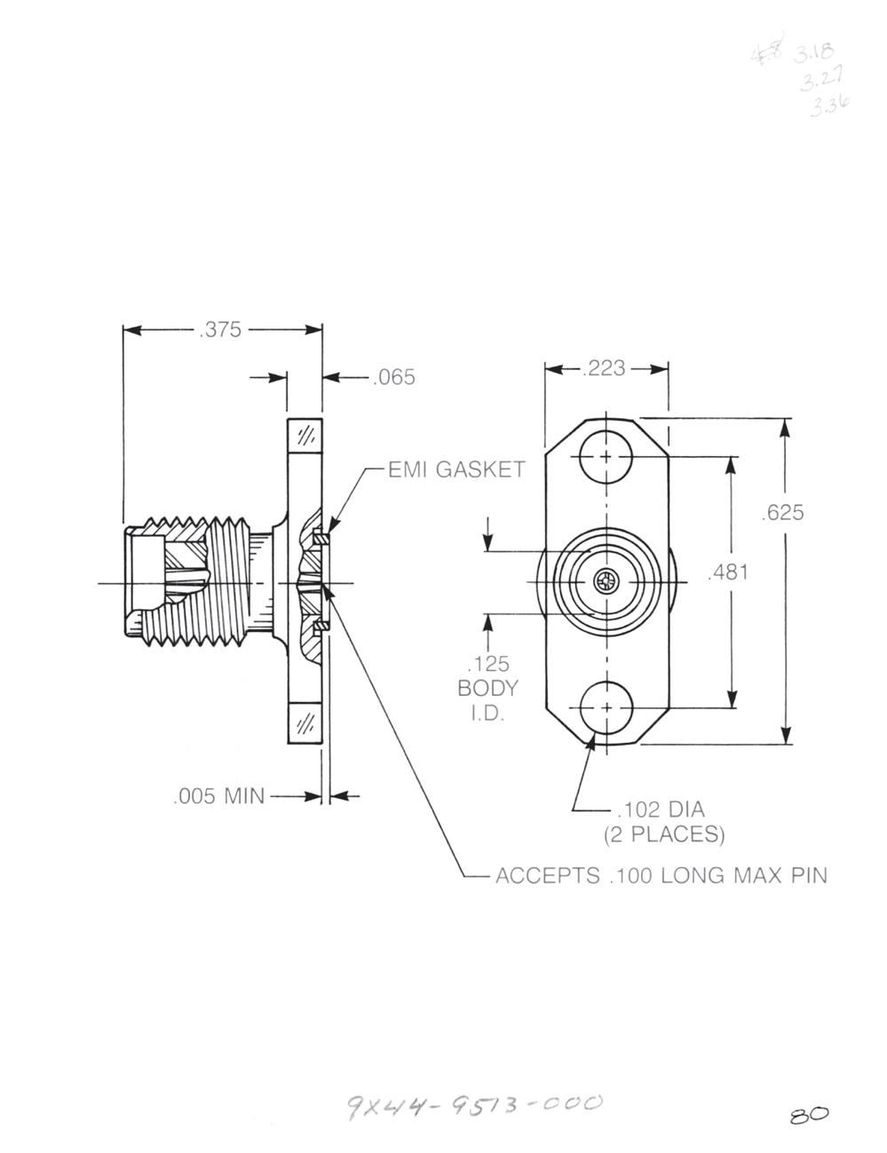
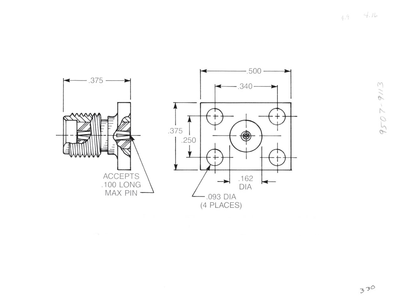
Straight Jack
• Rectangular flange
9507-9113-003
9507-9113-004 (Includes 920-69)
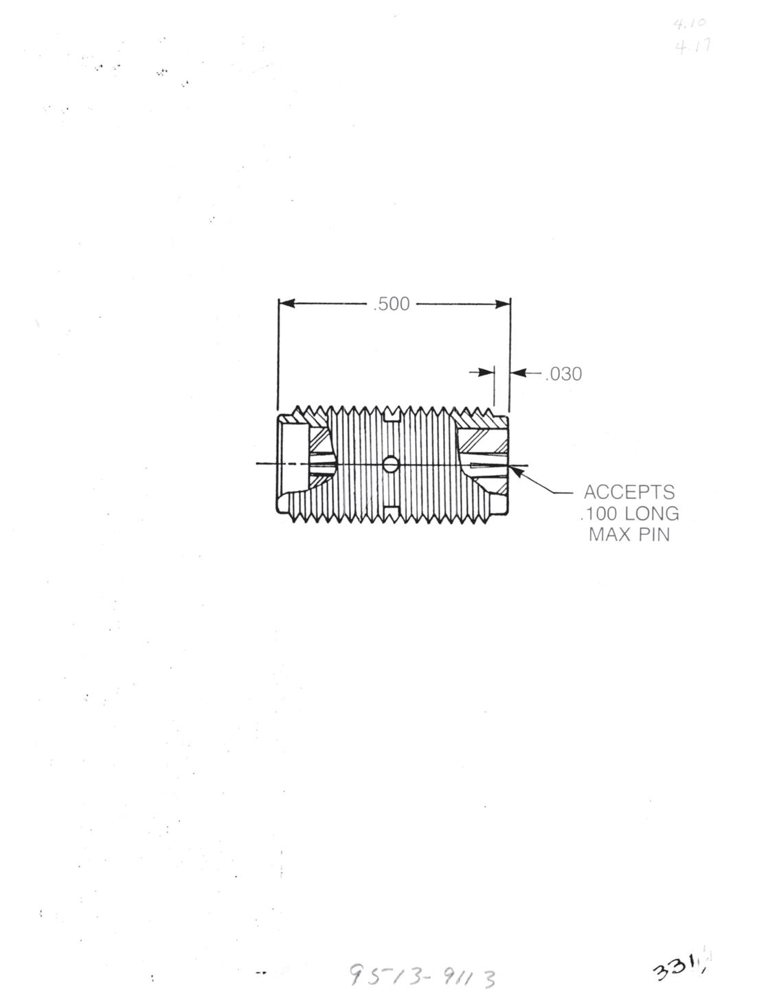
Straight Jack
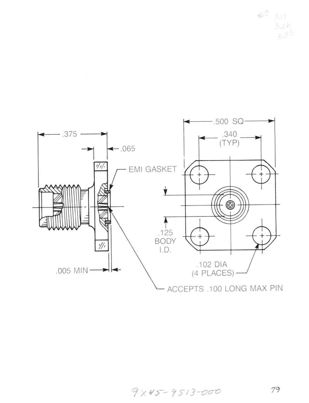
• Screw-in mounting
9513-9113-009
9513-9113-012 (Includes 920-69)
These connectors require a minimum package wall thickness of 0.250˝ for proper retention.
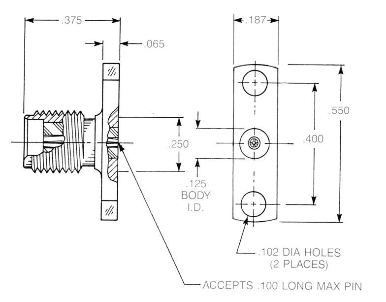
Straight Jack
• Knurl mount
9533-9113-003
9533-9113-002 (Includes 920-69)
These connectors require a minimum package wall thickness of 0.235˝ for proper retention.
Solder-In Hermetic Seal
See page 2-41 for material and finish specifications and mounting dimensions.
2-49
Simplification
Go online for data sheets and assembly instructions. Visit www.radiall.com/AEP and enter the part number.
SMA
is Our Innovation.
SMA
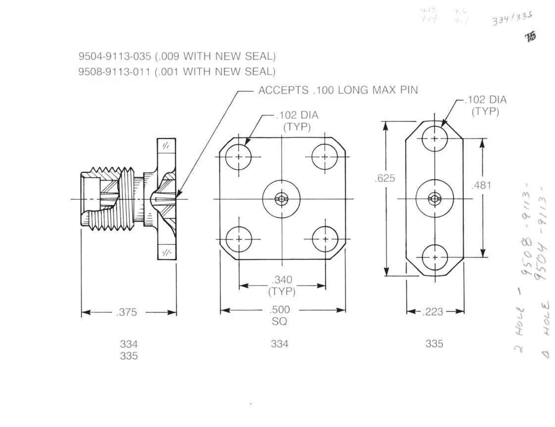
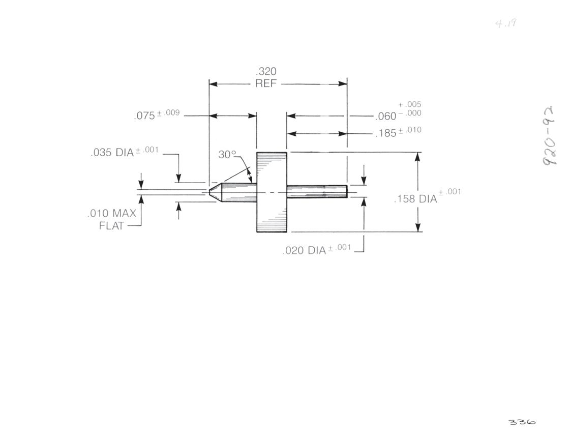
Hermetic Seal Launchers for 0.036˝ Diameter Pins
The hermetic seal launchers shown here are designed for use with hermetic seals having a 0.036˝ diameter pin on the connector (outer) side and a 0.020˝ diameter pin on the circuit (inner) side. The seal outer ring is 0.158˝ diameter. The contact and insulator diameters are constant through these connectors since they do not require the internal compensation featured in the launchers for smaller seals. The large outer diameter of the seals precludes the use of EMI gaskets on these connectors.
Straight Jack
• ½˝ Square flange
Optional packaging: 9504-9113-009
9504-9113-035 (Includes 920-92)
Straight Jack
• 2-hole flange
Optional packaging: 9508-9113-001
9508-9113-011 (Includes 920-92)
Straight Jack
• ³⁄8˝ Square flange
Optional packaging: 9576-9113-003
9576-9113-004 (Includes 920-92)
2-50
Go online for data sheets and assembly instructions. Visit www.radiall.com/AEP and enter the part number.
Hermetic Seal Launchers for 0.036˝ Diameter Pins
Straight Jack
• Rectangular flange
9507-9113-005
9507-9113-006 (Includes 920-92)
Straight Jack
• Screw-in mounting
9513-9113-008
9513-9113-013 (Includes 920-92)
These connectors require a minimum package wall thickness of 0.250˝ for proper retention.
Straight Jack
• Knurl mount
9533-9113-001
9533-9113-004 (Includes 920-92)
These connectors require a minimum package wall thickness of 0.235˝ for proper retention.
Solder-In Hermetic Seal P/N 920-92
See page 2-41 for material and finish specifications and mounting dimensions.
2-51
Go online for data sheets and assembly instructions. Visit www.radiall.com/AEP and enter the part number.
SMA Simplification is Our Innovation.
Adapters Within Series
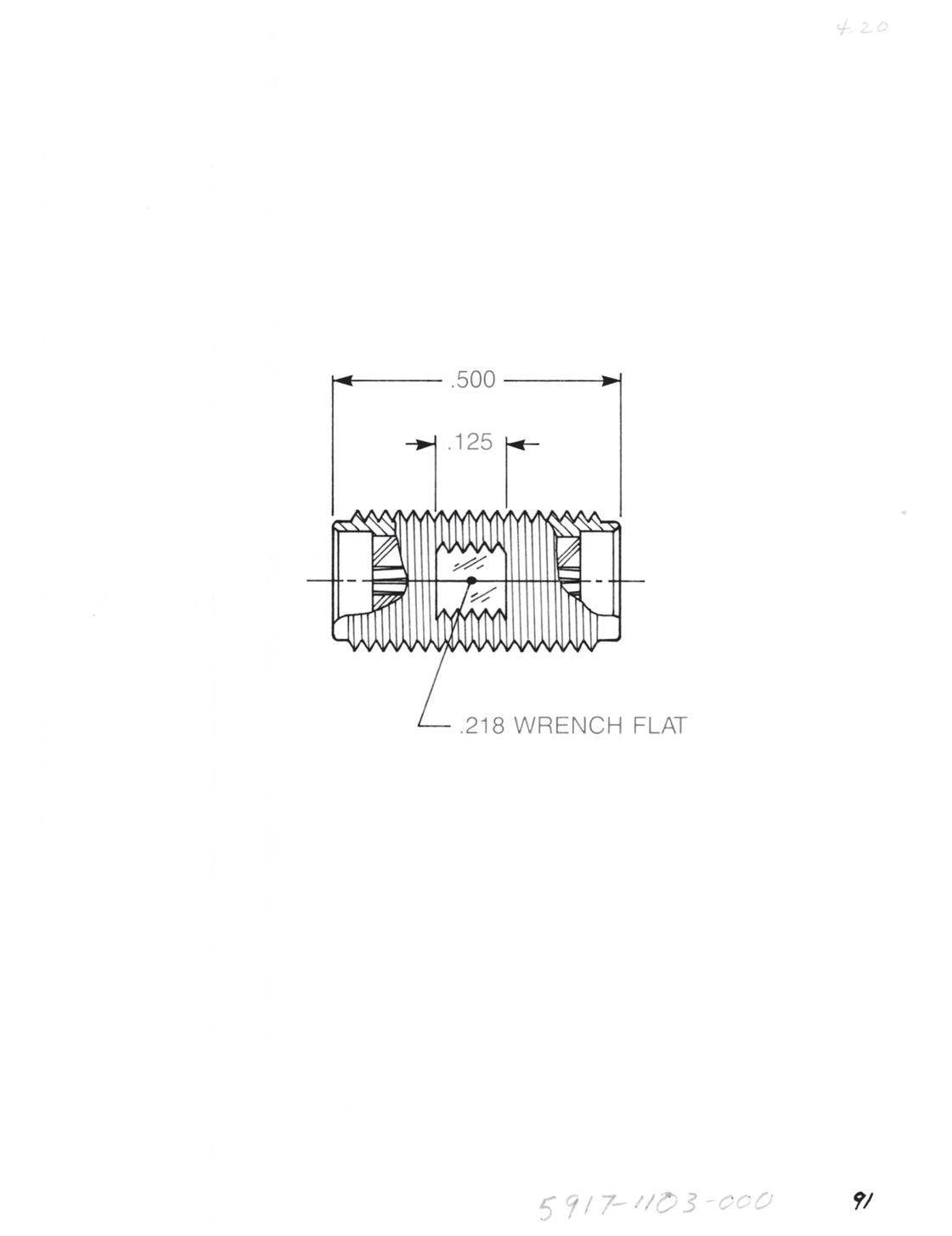
Straight Adapter
• Jack to jack
• Connects two plugs
Captive contact:
5917-1103-000 (Gold-plated)
5917-9103-000 (Passivated)
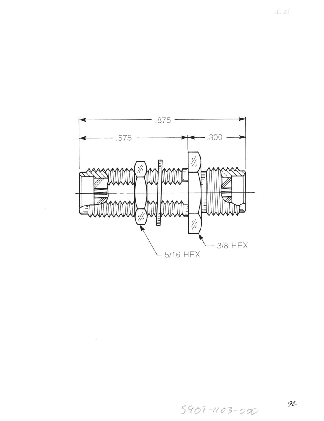
Straight Bulkhead Mounted Adapter
• Jack to jack
• Connects two plugs
Captive contact:
5909-1103-000 (Gold-plated)
5909-9103-000 (Passivated)
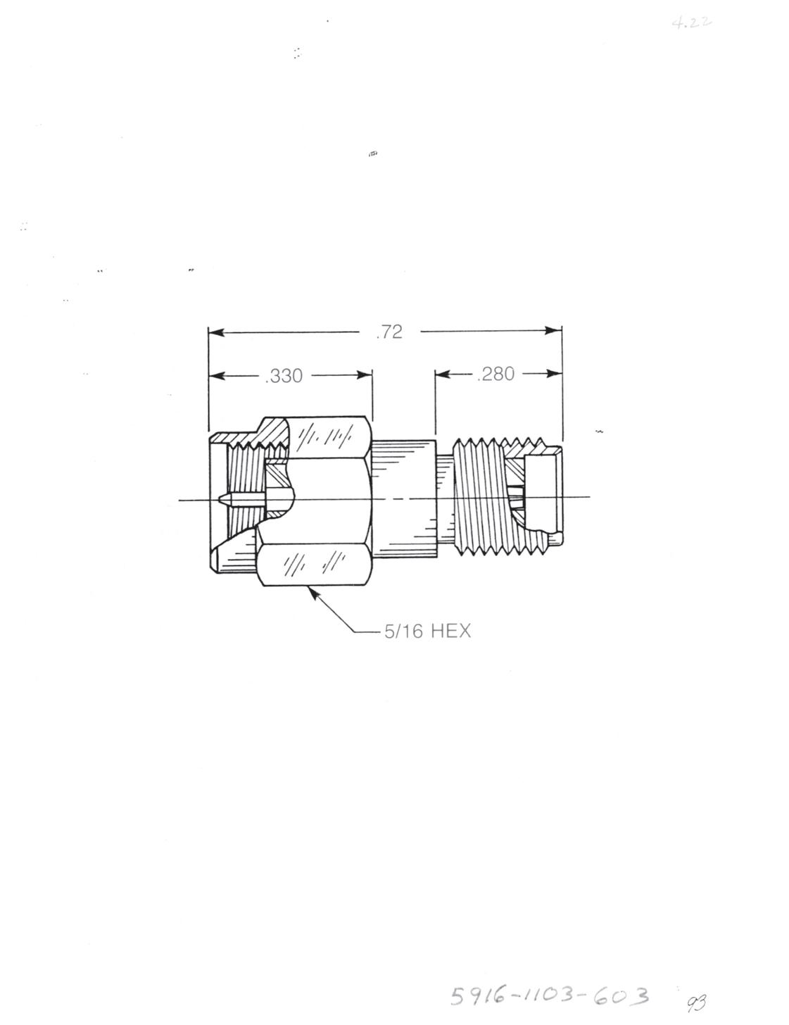
Straight Adapter
• Jack to plug
• Prevents damage to equipment-mounted jacks during frequent mating and unmating
Captive contact:
5916-1103-603 (Gold-plated)
5916-9103-603 (Passivated)
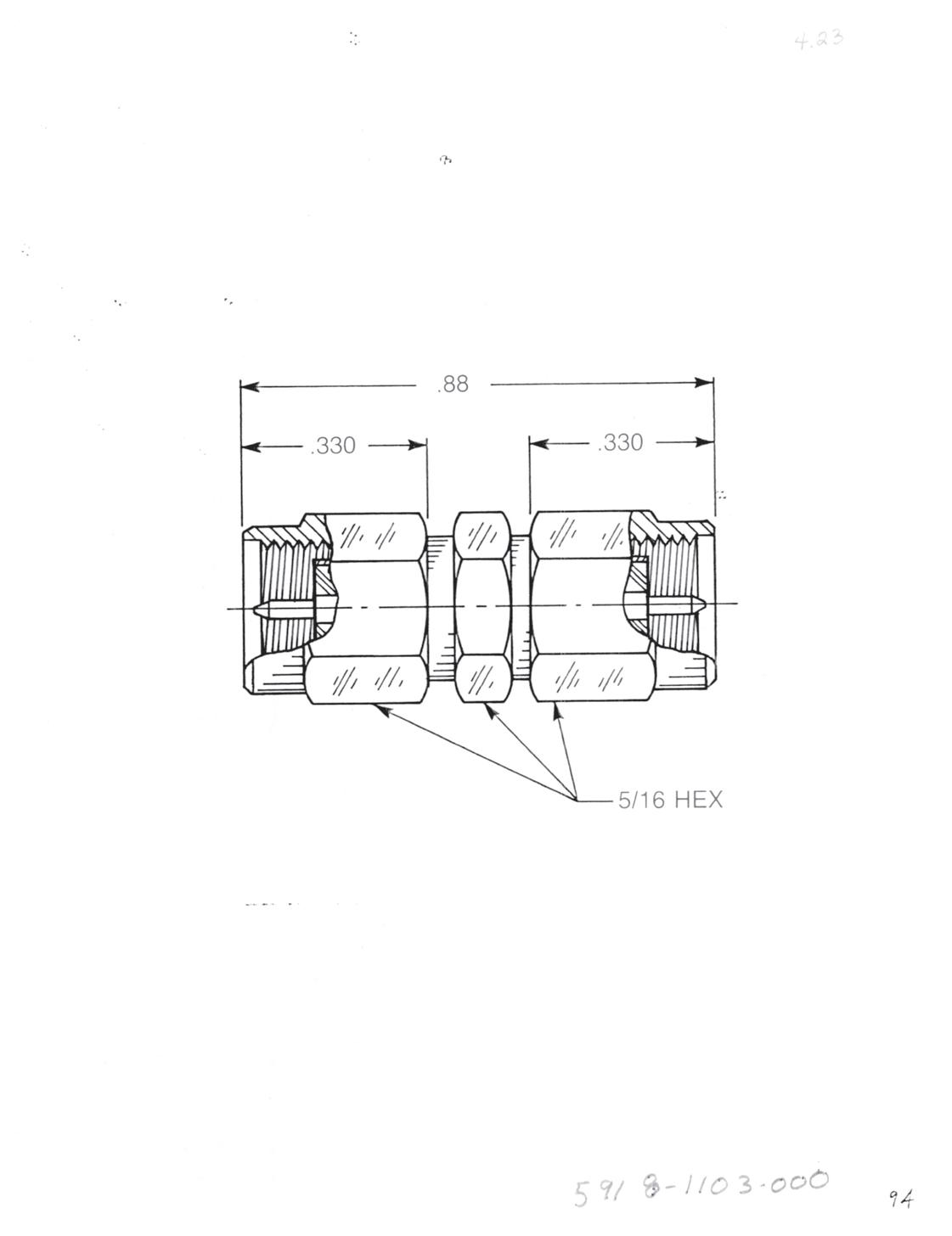
Straight Adapter
• Plug to plug
• Connects two jacks
Captive contact:
5918-1103-000 (Gold-plated)
5918-9103-000 (Passivated)
Visit www.radiall.com/AEP and enter the part number.
Adapters Within Series
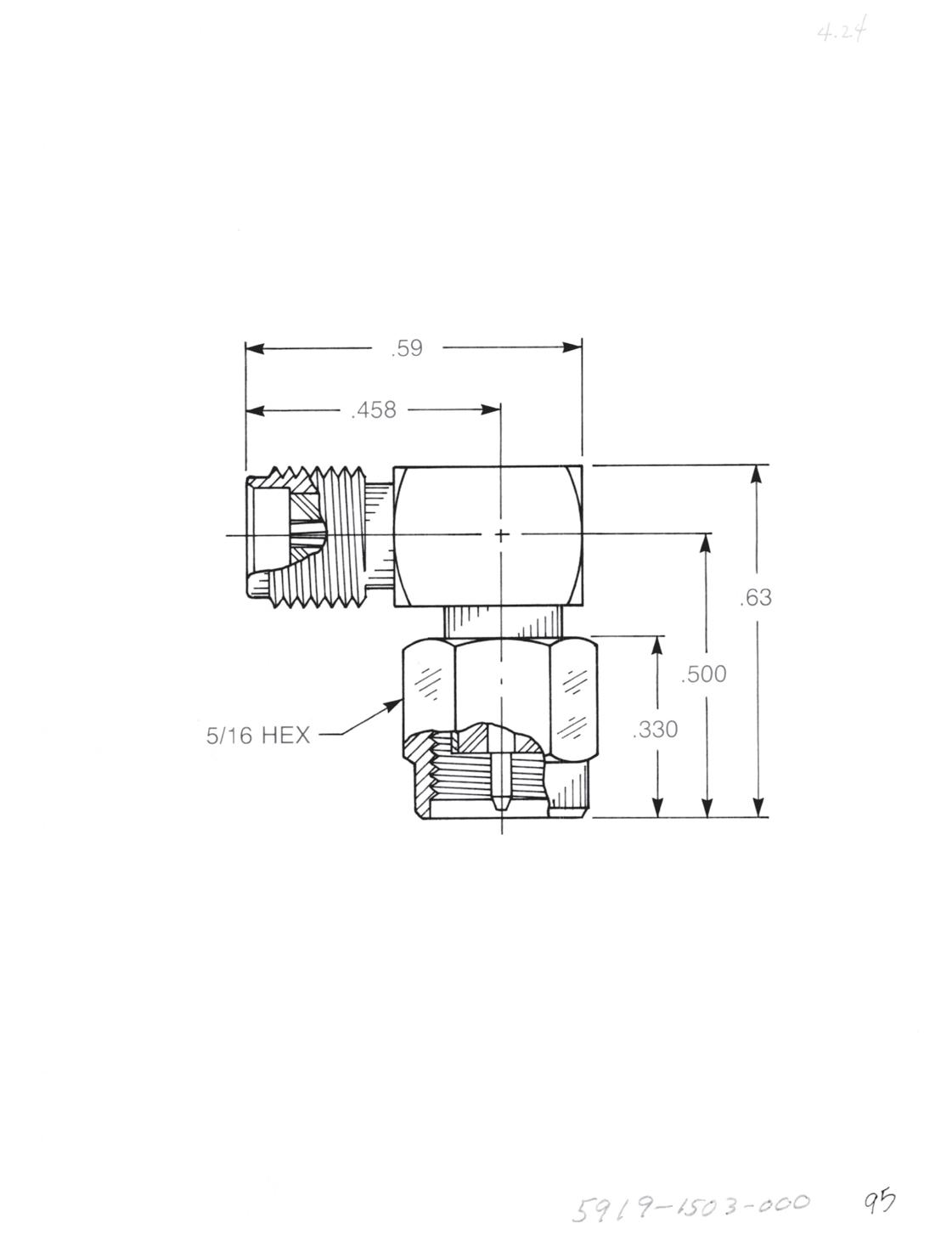
Right Angle Adapter
• Jack to plug
• Connects one jack and one plug
5919-1503-000 (Gold-plated)
5919-9503-000 (Passivated)
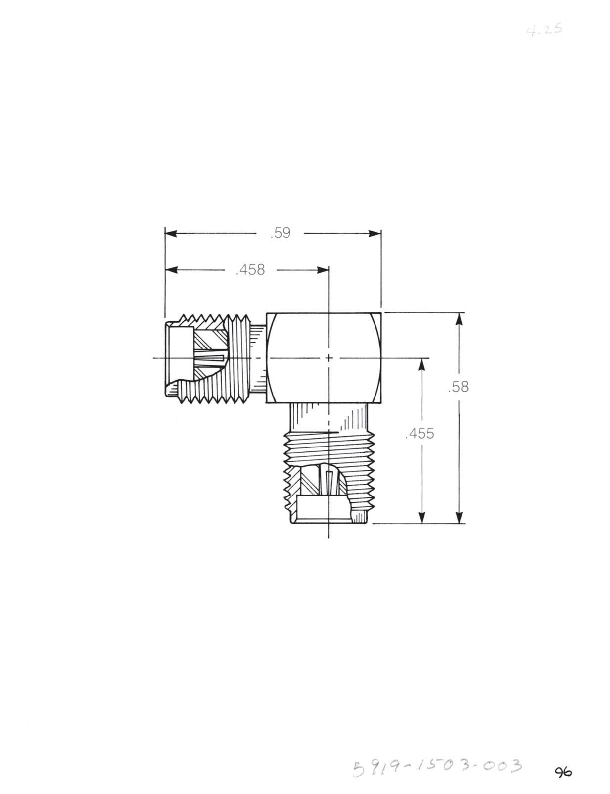
Right Angle Adapter
• Jack to jack
• Connects two plugs
5919-1503-003 (Gold-plated)
5919-9503-003 (Passivated)
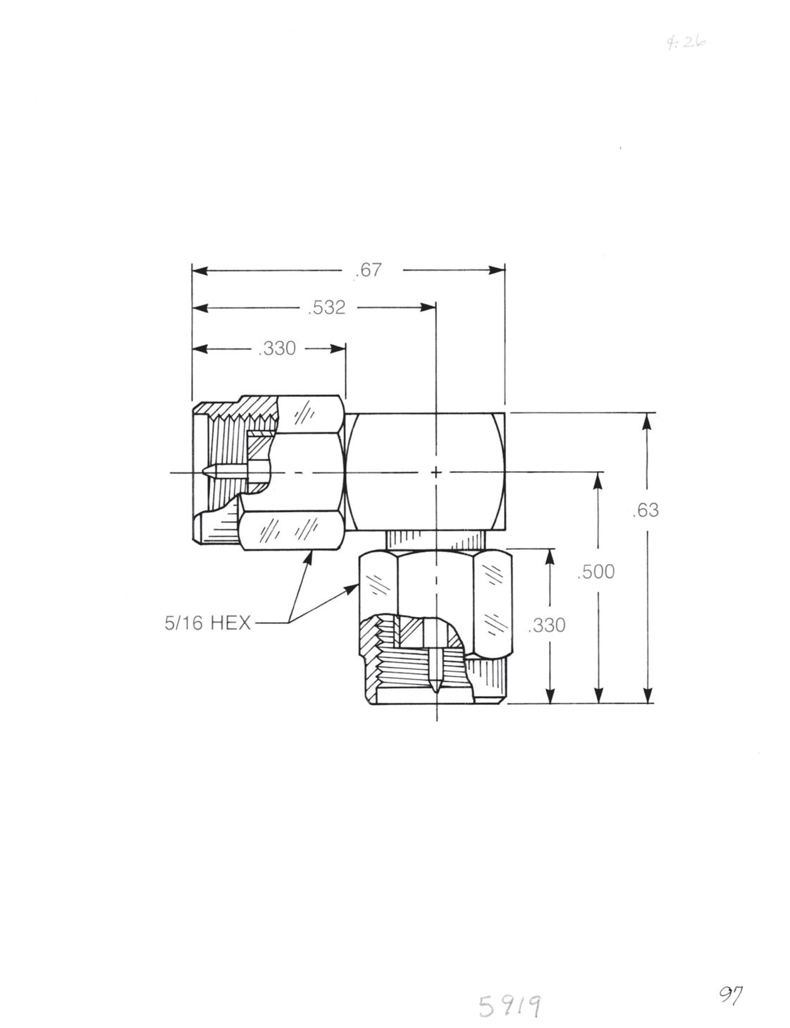
Right Angle Adapter
• Plug to plug
• Connects two jacks
5919-1503-001 (Gold-plated)
5919-9503-001 (Passivated)
2-53
Simplification is Our Innovation. Go online for data sheets and assembly instructions. Visit www.radiall.com/AEP and enter the part number.
SMA
SMA
Tee Adapters - Resistive Terminations
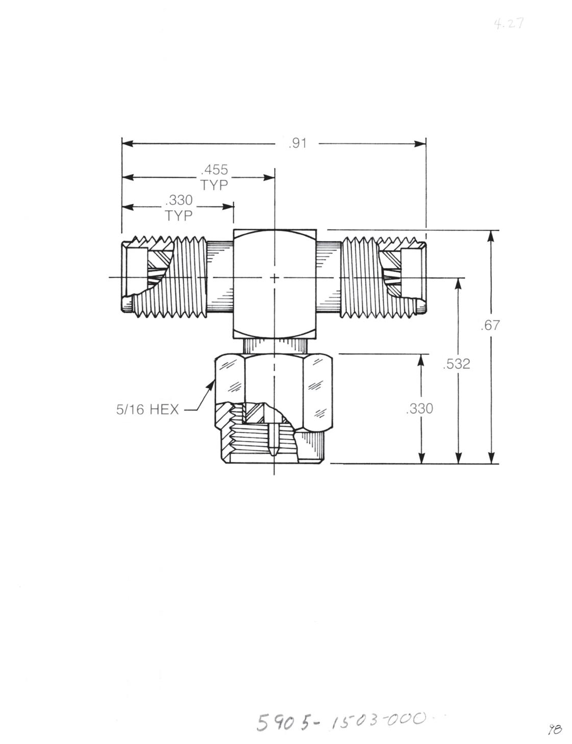
Tee Adapter (Unmatched Power Divider)
• Jack to plug to jack
• Connects two plugs and one jack
5905-1503-000 (Gold-plated)
5905-9503-000 (Passivated)
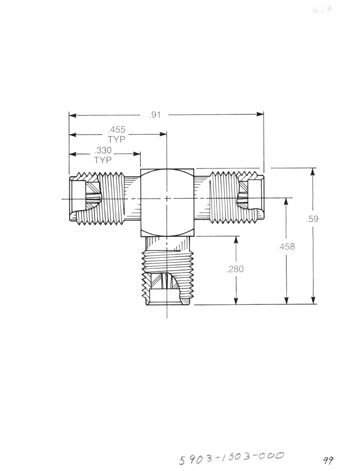
Tee Adapter (Unmatched Power Divider)
• Jack to jack to jack
• Connects three plugs
5903-1503-000 (Gold-plated)
5903-9503-000 (Passivated)
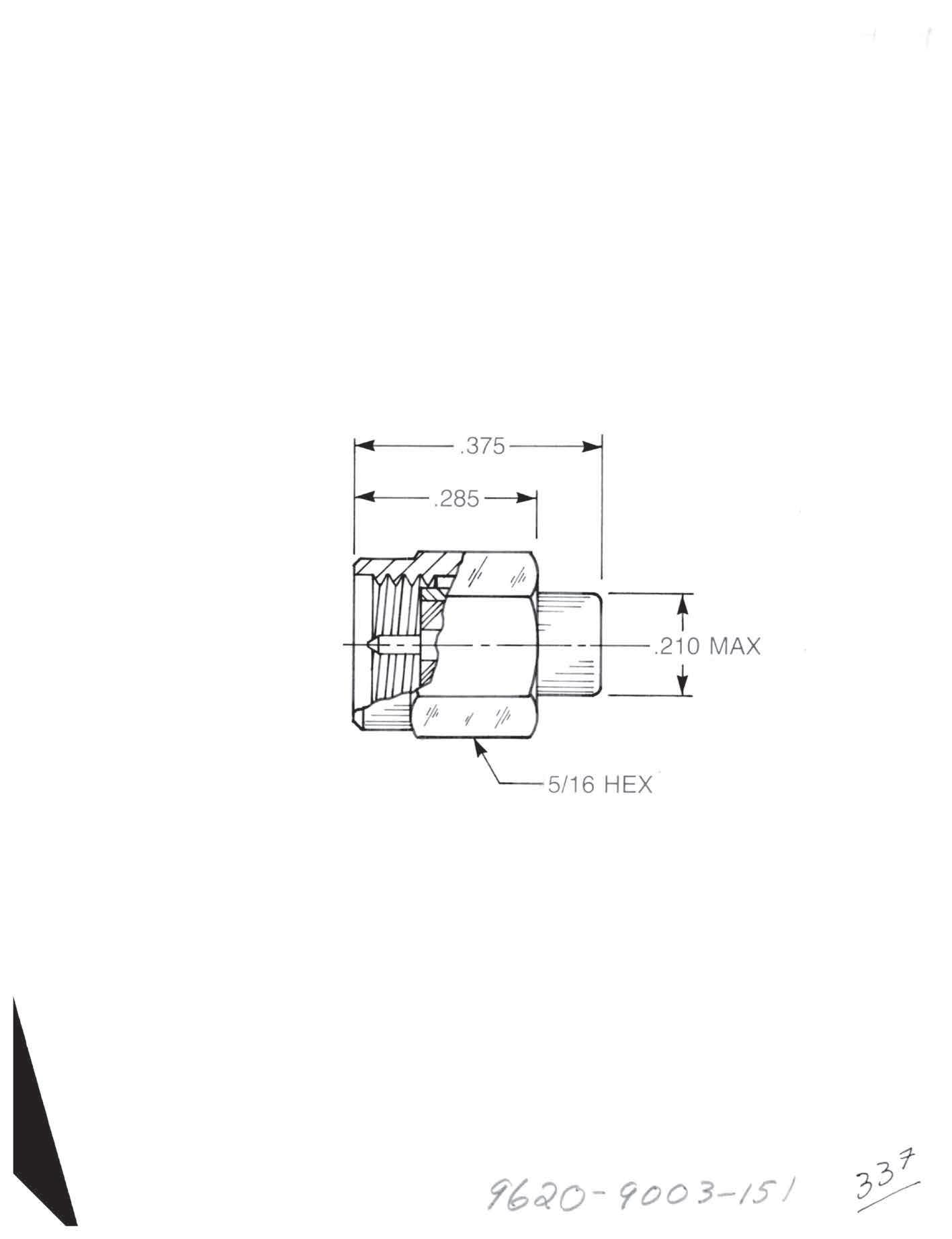
Plug Resistive Termination (Dummy Load)
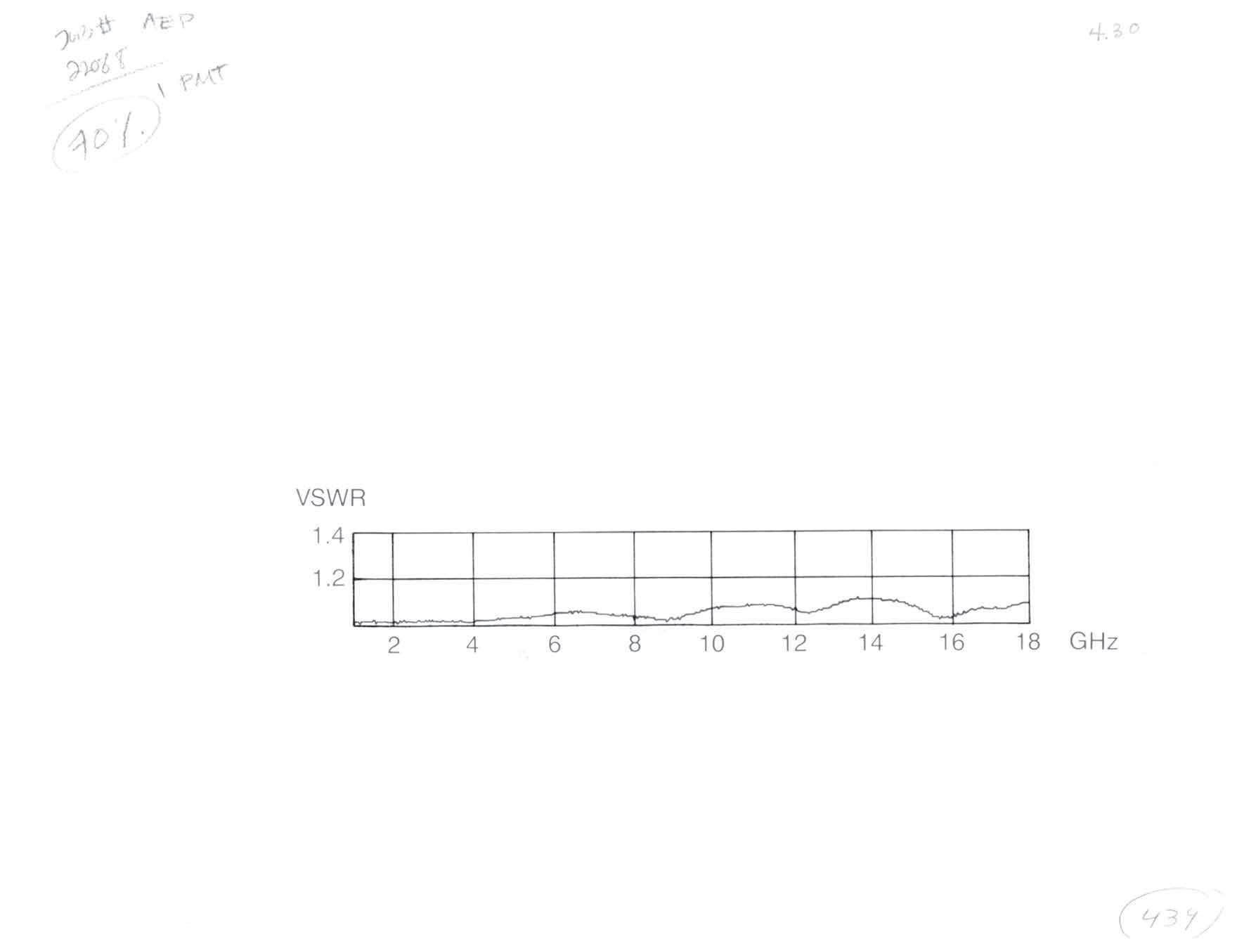
VSWR 1.15: 1 max to 18 GHz
Maximum average power: 1 W
Peak power: 1.5 W
9620-9003-151 (Passivated)
Visit www.radiall.com/AEP and enter the part number.
SIMPLIFICATION IS OUR INNOVATON Visit www.radiall.com for more information. SECTION 3 SMB/SMC/SLB
3-1 Simplification is Our Innovation. Go online for data sheets and assembly instructions. Visit www.radiall.com/AEP and enter the part number. Specifications 3-4 SMB SERIES Cable Plugs 3-6 Cable Jacks 3-8 Bulkhead Receptacles 3-9 P.C. Board Receptacles 3-12 Stripline Receptacles 3-14 Adapters Within Series 3-15 Resistive Terminations 3-16 SMC SERIES Cable Plugs 3-17 Cable Jacks 3-18 Bulkhead Receptacles 3-20 P.C. Board Receptacles 3-21 Panel (Flange Mount) Receptacles 3-22 Stripline Receptacles 3-23 Adapters Within Series 3-24 Resistive Terminations 3-25 SLB SERIES Cable Plugs 3-26 Cable Jacks ...................................................................................................................................................................................3-28 Bulkhead Receptacles 3-30 P.C. Board Receptacles 3-32 Float Mount/Blind Mate Connectors 3-35 SECTION 3 TABLE OF CONTENTS
AEP SMB series connectors meet or exceed MIL-PRF-39012 performance requirements, offering good electrical performance up to 10 GHz. Their snap-on mating makes them ideal for use in confined areas where the use of wrenches is not practical.
AEP SMC series connectors offer the same low cost and small size as SMB series, but their screw-on mating provides extra mating security. Frequency range: DC-10 GHz.
AEP SLB series connectors are similar to SMB series, but have slide-on mating for use in multiple mounting or rack and panel applications. SLB plugs will mate with SMB jacks.
Standard cables for use with these connectors are shown at the bottom of the appropriate product pages. A complete listing of cable groups is on page 13-6. All the items shown are available with either gold or nickelplated bodies; part numbers for each finish are shown in the product section. The index listing for each connector shows the appropriate cable assembly instruction. Assembly instructions start on page 13-14.
Factory-built cable assemblies using these connectors are available from AEP.
3-2
Go online for data sheets and assembly instructions. Visit www.radiall.com/AEP and enter the part number.
SMB/SMC/SLB
SMB
INTERFACE DIMENSIONS
PER MIL-STD-348
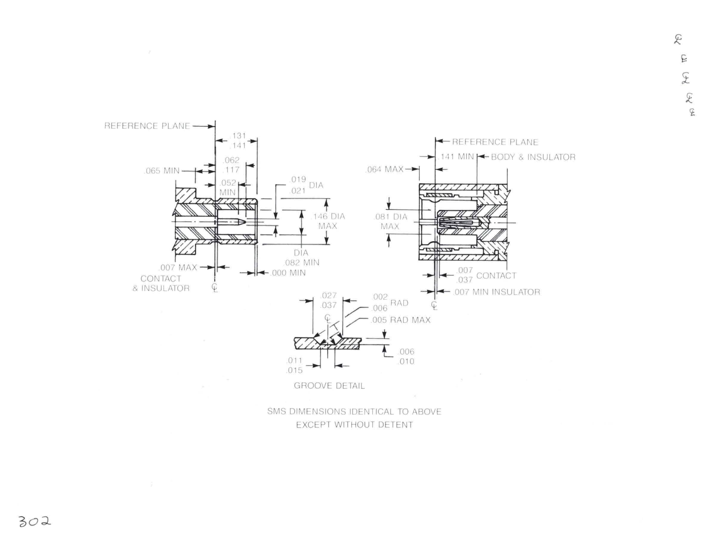
SLB dimensions identical to above except without detent.
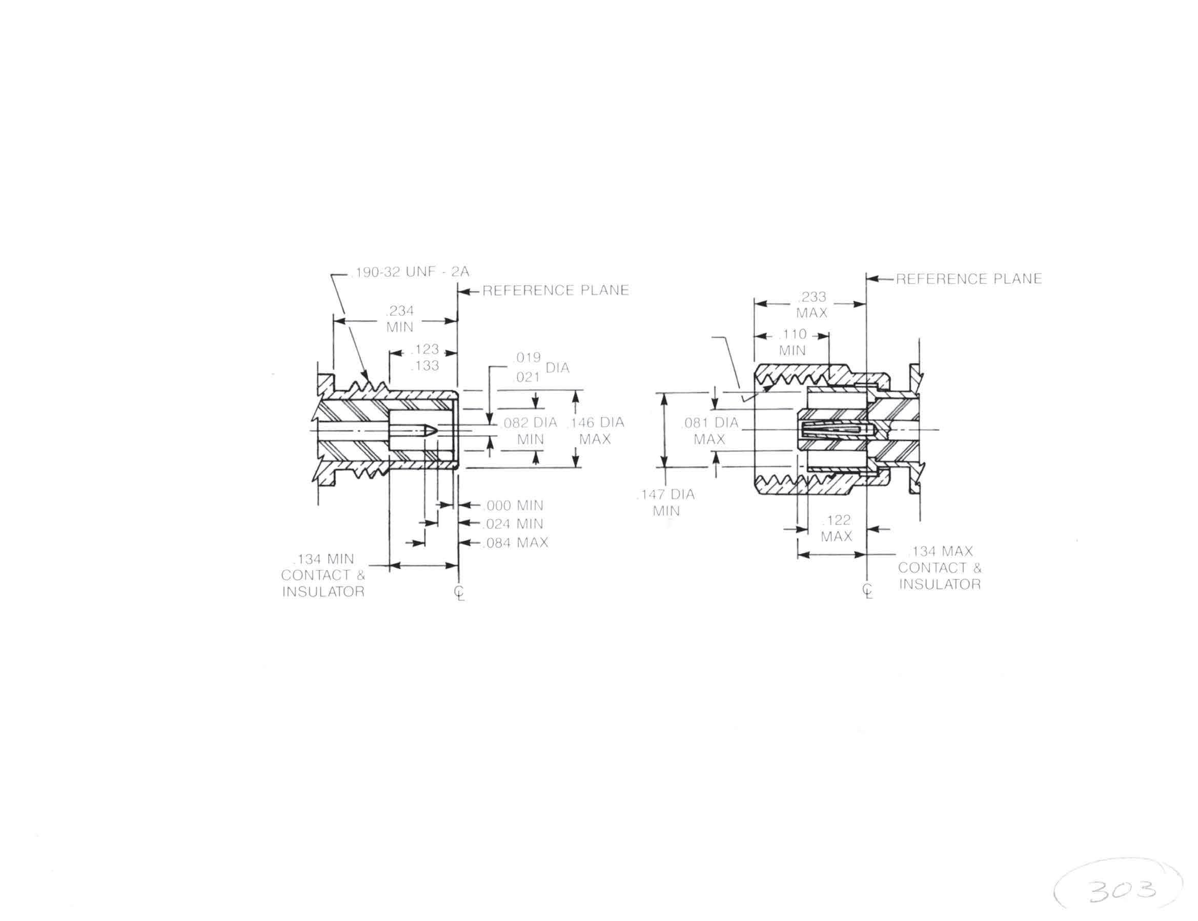
SMC
INTERFACE DIMENSIONS
PER MIL-STD-348
3-3
Visit www.radiall.com/AEP and enter the part number.
SMB/SMC Simplification is Our Innovation.
Specifications
SPECIFICATIONS MIL-PRF-39012
MATERIALS:
Body components, male contacts: Brass per ASTM B16, alloy 360, 1/2 hard
Female contact: Beryllium copper per ASTM B196, condition HT
Insulators: Teflon TFE per ASTM-D-1710
FINISH:
Center contacts: Gold-plated per MIL-G-45204
All other parts finished to meet MIL-PRF-39012 corrosion requirements.
ELECTRICAL:
Impedance: 50 Ω
Frequency range: SMC: DC-10 GHz. SMB, SLB: DC-4 GHz
Voltage rating:
RG178: 250 VRMS, sea level
RG316: 335 VRMS, sea level
Insulation resistance: 1,000 MΩ min
VSWR:
SMB, SLB straight connector:
RG178: 1.30+[0.04×f (GHz)]
RG316: 1.25+[0.04×f (GHz)]
SMB, SLB right angle:
RG178: 1.45+[0.06×f (GHz)]
RG316: 1.35+[0.04×f (GHz)]
SMC straight connector:
RG178: 1.25+[0.04×f (GHz)]
RG316: 1.20+[0.04×f (GHz)]
SMC right angle:
RG178: 1.40+[0.06×f (GHz)]
RG316: 1.30+[0.04×f (GHz)]
Contact resistance:
Straight: 6 mΩ max initial, 8 mΩ max after environment.
Right angle: 12 mΩ max initial, 16 mΩ max after environment.
Dielectric withstanding voltage (sea level):
RG178: 750 VRMS
RG316: 1,000 VRMS
Corona level at 70,000 ft:
RG178: 185 VRMS
RG316: 250 VRMS
RF highpot at 5 MHz:
RG178: 500 VRMS
RG316: 700 VRMS
RF leakage:
SMB, SLB: -55 dB min, 2-3 GHz
SMC: -60 dB min, 2-3 GHz
Insertion loss:
SMB, SLB at 1.5 GHz:
Straight 0.30 dB max
Right angle 0.60 dB max
SMC at 4 GHz:
Straight 0.25 dB max
Right angle 0.50 dB max
MECHANICAL:
Force to engage: SMB, 14 lb max, SLB 6 lb max
Mating torque: SMC, 35-50 in-oz
Coupling nut pulloff resistance: SMC, 35 lb min
Contact retention (captive contact connectors): 4 lb min axial force
Durability: 500 mating cycles
ENVIRONMENTAL: (per MIL-STD-202)
Temperature rating: -65° C to + 165° C
Corrosion: Method 101, condition B, 5% salt solution
Vibration: Method 204, SMB, condition B
SMC, condition D
Mechanical shock: Method 213, SMB, condition B
SMC, condition C
Thermal shock: method 107, condition B
3-4 SMB/SMC/SLB Go online for data sheets and assembly instructions. Visit www.radiall.com/AEP and enter the part number.
Cable Attachment Methods
Simplification is Our Innovation.
All connectors in these series have captivated contacts which are soldered to the cable center conductor. The cable attachment methods shown have gripping force greater than the breaking strength of the cable.
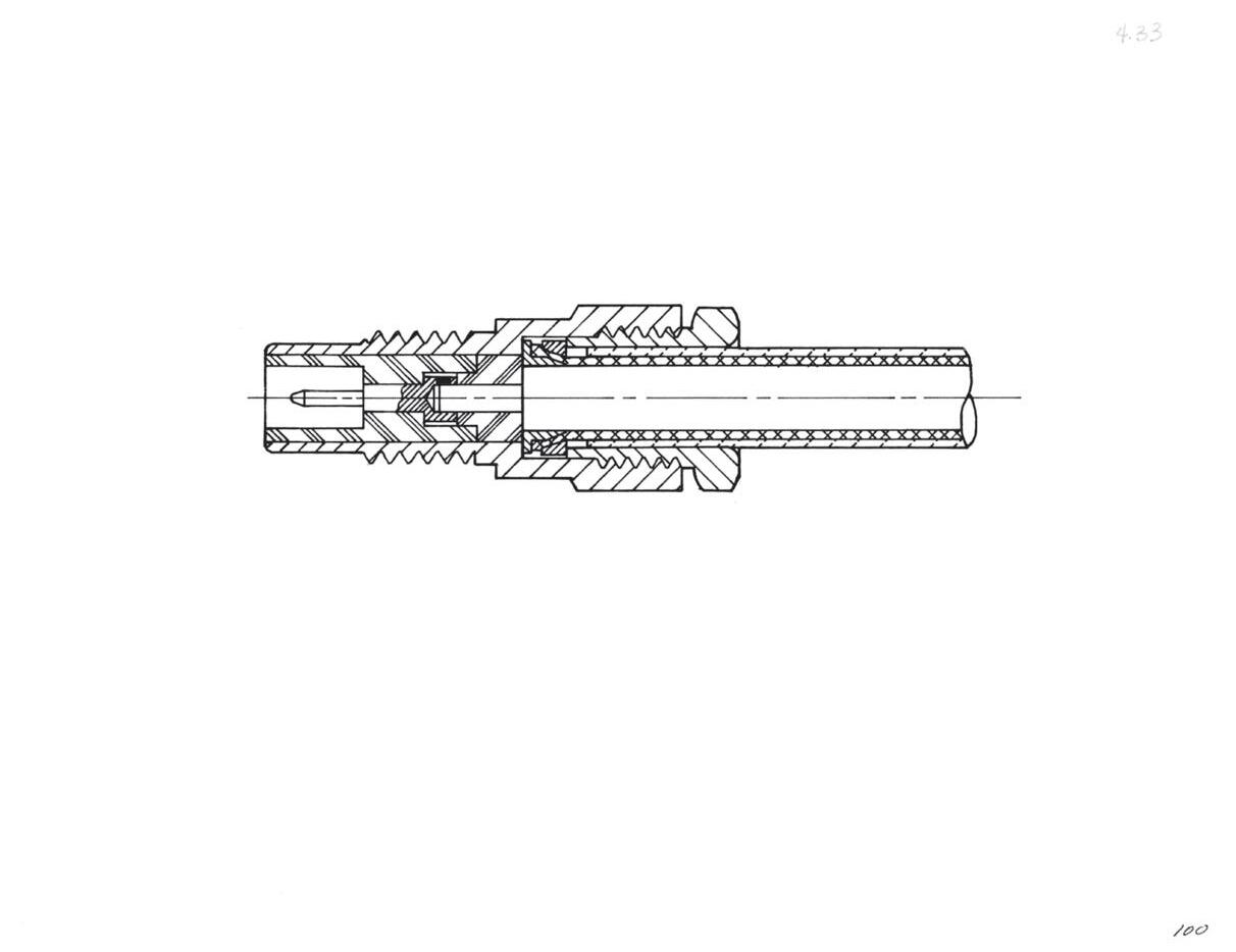
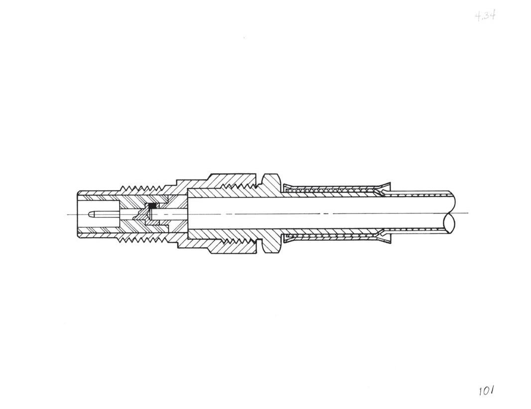
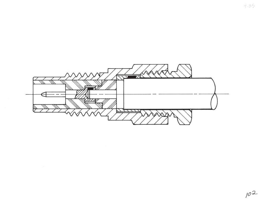
Clamp Type For Flexible Cable
These connectors can be assembled without special tooling and are field replaceable. They provide metal-to-metal clamping of the cable braid.
Crimp Type For Flexible Cable
Crimping the cable braid is the most reliable and repeatable method of cable assembly and provides support for the cable during flexure. AEP crimp type connectors are assembled quickly and easily using readily available commercial or MIL crimp tools.
Solder-Clamp For Semi-Rigid Cable
This method allows retrimming of the cable dielectric, if necessary, during assembly. Connectors can be repositioned relative to the cable after assembly by loosening the clamp nut. Solder-clamp connectors are field replaceable without requiring special tools.
3-5 SMB/SMC/SLB
Go online for data sheets and assembly instructions. Visit www.radiall.com/AEP and enter the part number.
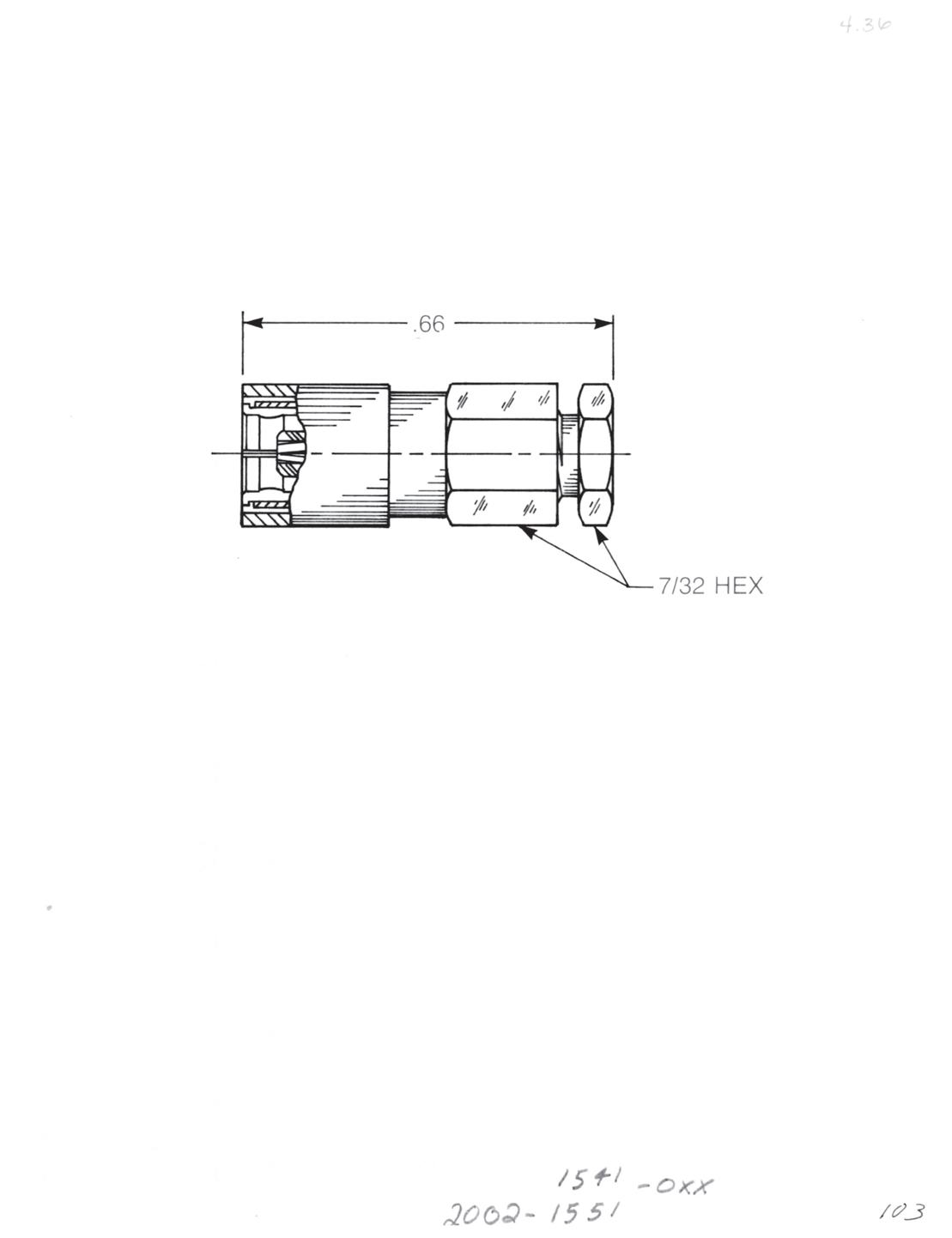
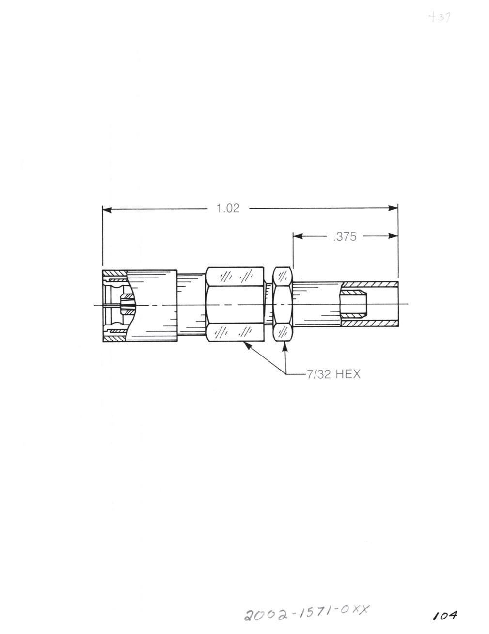
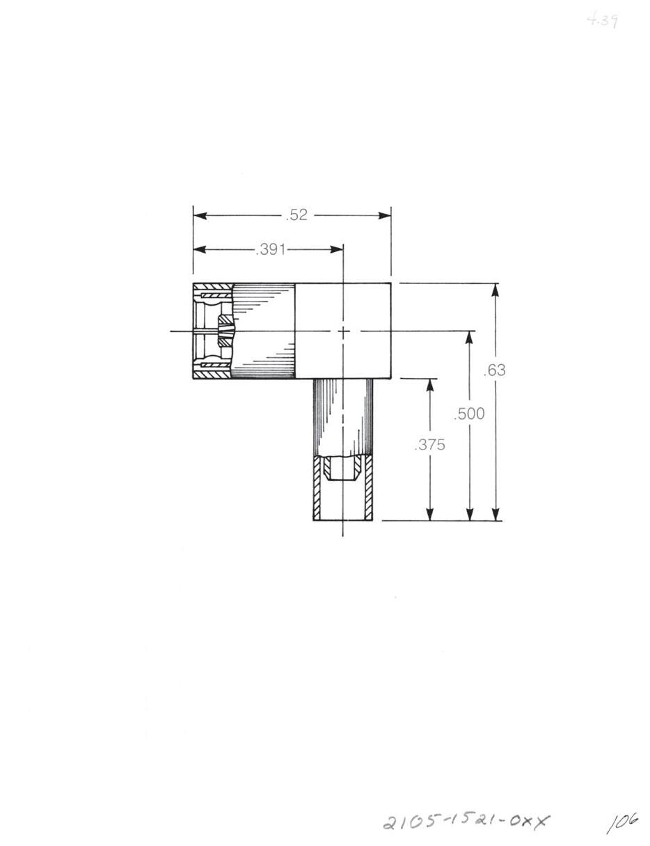
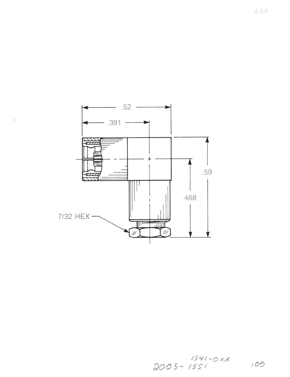
Straight Female Cable Plug
Clamp type for flexible cable: 2002-1551-0XX (Gold-plated) 2002-7551-0XX (Nickel-plated)
Solder-clamp for semi-rigid cable: 2002-1541-0XX (Gold-plated) 2002-7541-0XX (Nickel-plated)
Straight Female Cable Plug
Crimp type for flexible cable: 2002-1571-0XX (Gold-plated) 2002-7571-0XX (Nickel-plated)
Right Angle Female Cable Plug
Clamp type for flexible cable: 2005-1551-0XX (Gold-plated) 2005-7551-0XX (Nickel-plated)
Solder-clamp for semi-rigid cable: 2005-1541-0XX (Gold-plated) 2005-7541-0XX (Nickel-plated)
Right Angle Female Cable Plug
Crimp type for flexible cable: 2105-1521-0XX (Gold-plated) 2105-7521-0XX (Nickel-plated)
Substitute XX with the Appropriate Cable Group Below
02 RG178, RG196, M17/93, M17/169
03 RG174, RG179, RG316, M17/113, M17/119, M17/172, M17/173
05 RG178DS, RG196DS
09 0.141˝ semi-rigid, RG402, M17/130
10 0.085˝ semi-rigid, RG405, M17/133
19 RG174DS, RG316DS, M17/152, Times RD316
3-6 Go online for data sheets and assembly instructions. Visit www.radiall.com/AEP and enter the part number.
Bulkhead Mounted Cable Plugs
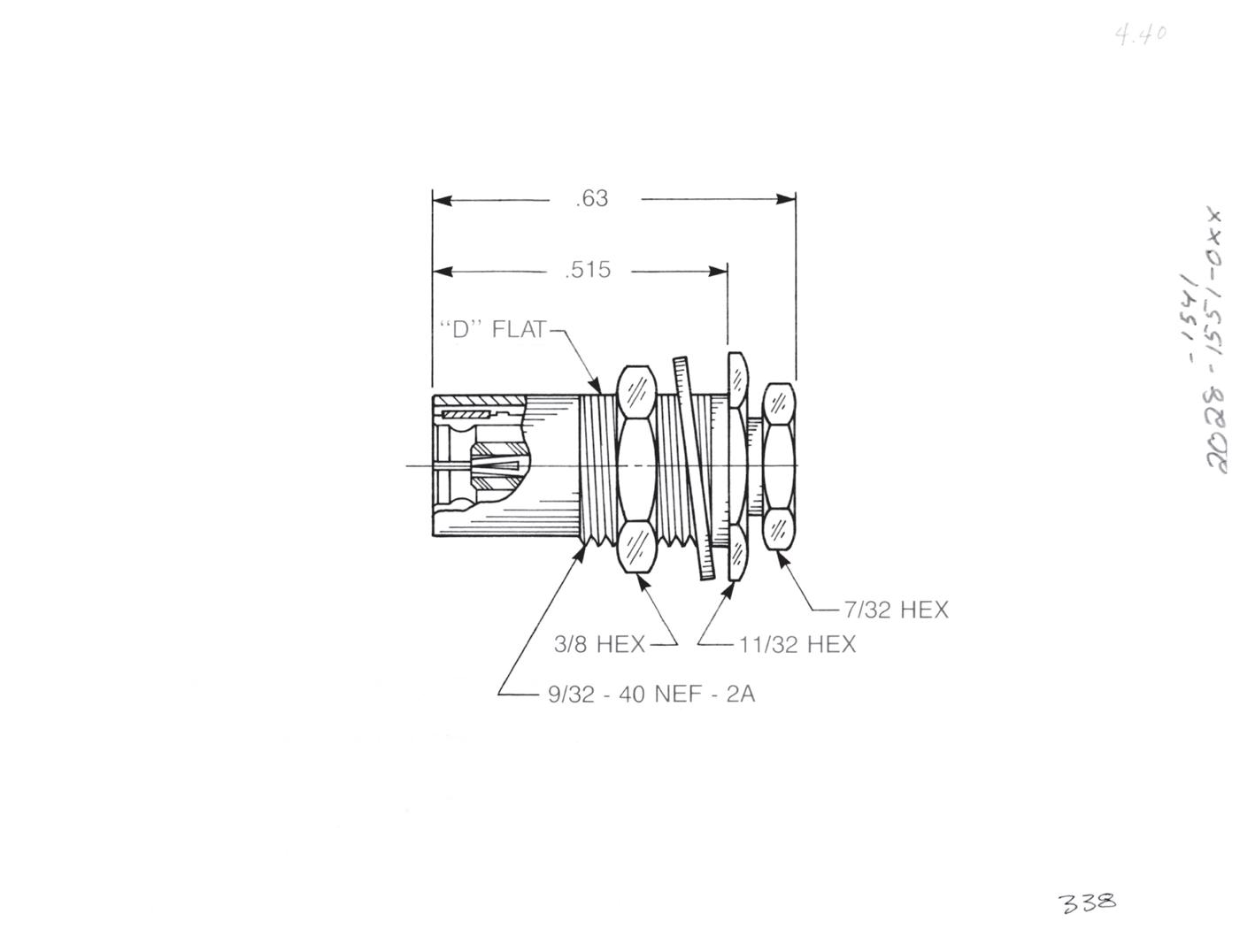
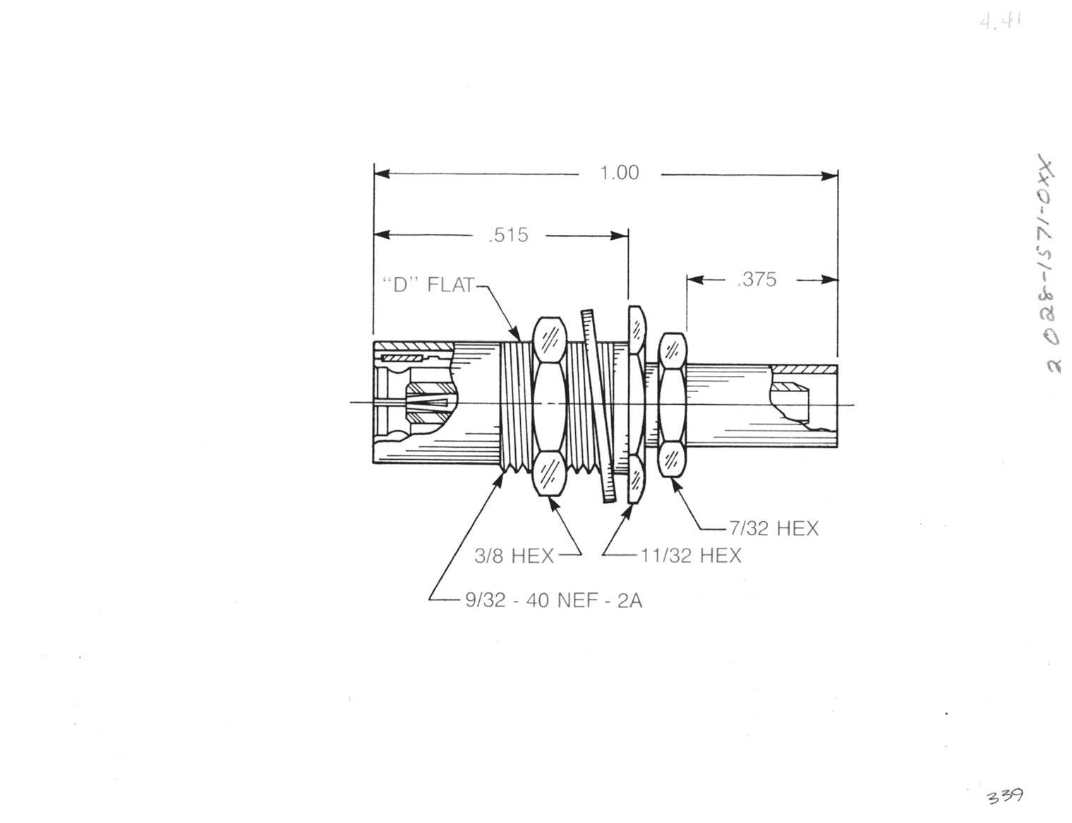
Bulkhead Mounted Straight Cable Plug
Clamp type for flexible cable: 2028-1551-0XX (Gold-plated) 2028-7551-0XX (Nickel-plated)
Solder-clamp for semi-rigid cable: 2028-1541-0XX (Gold-plated) 2028-7541-0XX (Nickel-plated)
Bulkhead Mounted Straight Cable Plug
Crimp type for flexible cable: 2028-1571-0XX (Gold-plated) 2028-7571-0XX (Nickel-plated)
Substitute XX with the Appropriate Cable Group Below
RG196, M17/93, M17/169
RG174, RG179, RG316, M17/113, M17/119, M17/172, M17/173
semi-rigid, RG402, M17/130
semi-rigid, RG405, M17/133
RG174DS, RG316DS, M17/152, Times RD316
Designed for use with 0.093˝ max thick panel.
3-7 SMB
Go online for data sheets and assembly instructions. Visit www.radiall.com/AEP and enter the part number.
Simplification is Our Innovation.
02
09 0.141˝
03
10 0.085˝
05 RG178DS,
19
RG178,
RG196DS
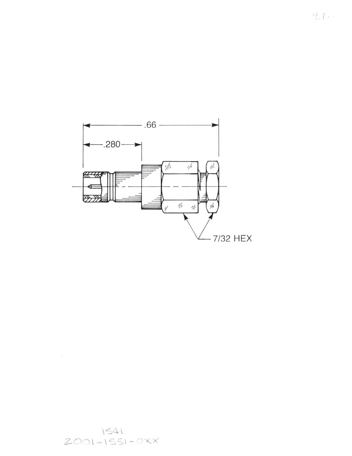
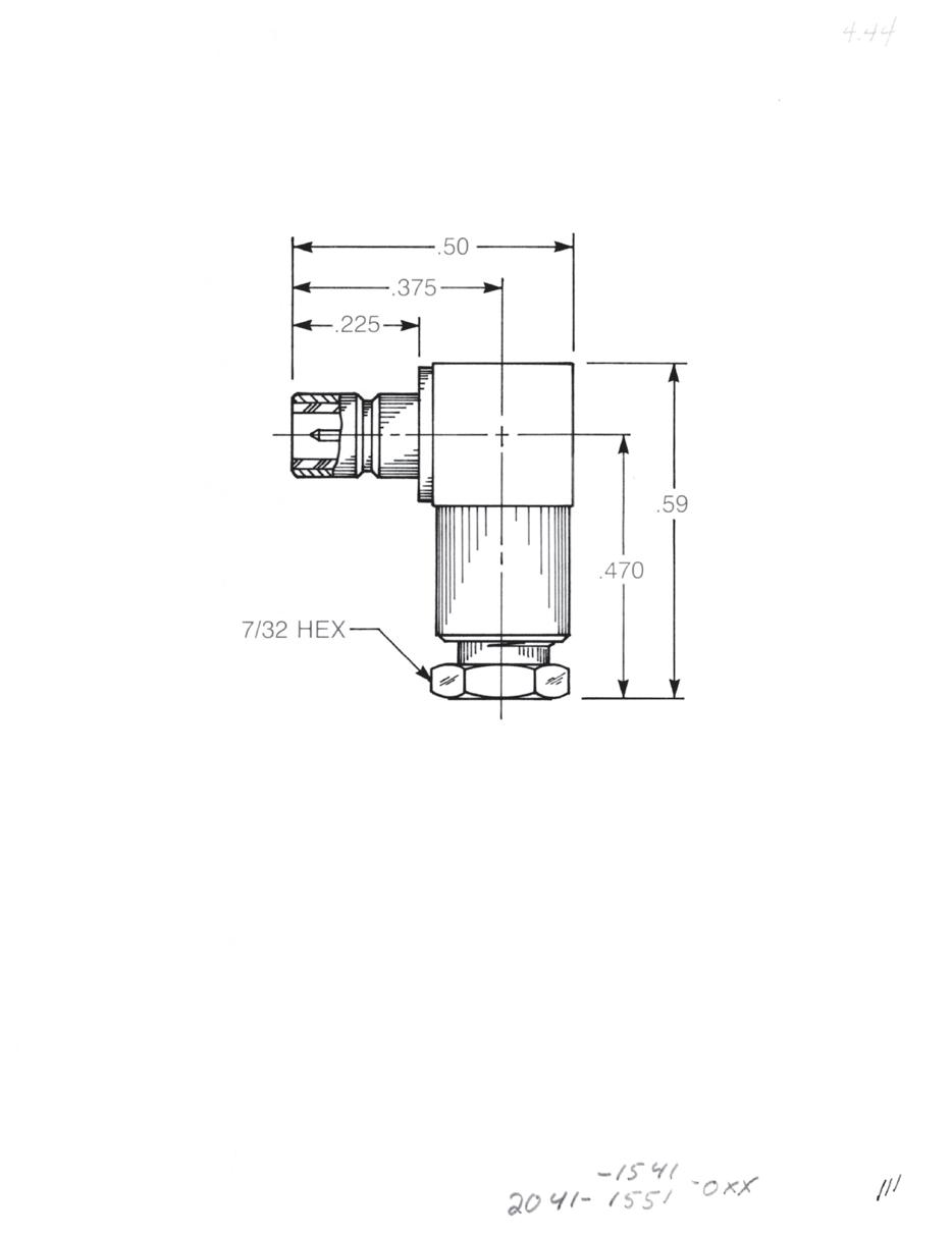
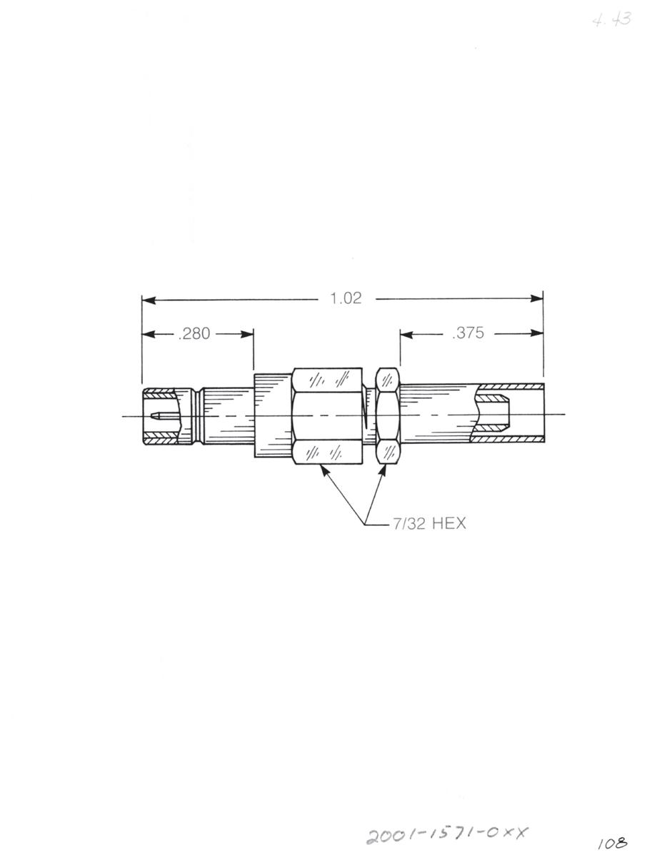
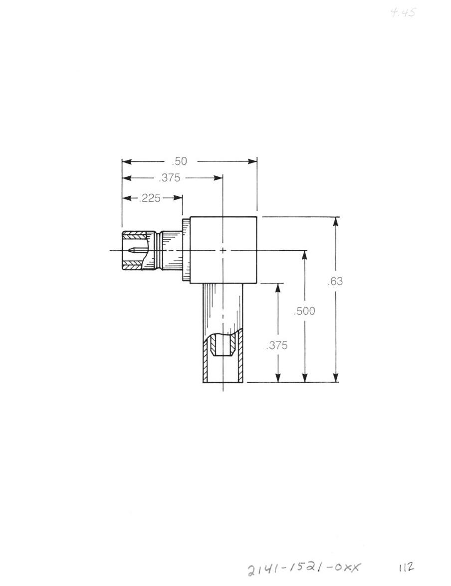
Straight Male Cable Jack
Clamp type for flexible cable: 2001-1551-0XX (Gold-plated) 2001-7551-0XX (Nickel-plated)
Solder-clamp for semi-rigid cable: 2001-1541-0XX (Gold-plated) 2001-7541-0XX (Nickel-plated)
Straight Male Cable Jack
Crimp type for flexible cable: 2001-1571-0XX (Gold-plated) 2001-7571-0XX (Nickel-plated)
Right Angle Male Cable Jack
Clamp type for flexible cable: 2041-1551-0XX (Gold-plated) 2041-7551-0XX (Nickel-plated)
Solder-clamp for semi-rigid cable: 2041-1541-0XX (Gold-plated) 2041-7541-0XX (Nickel-plated)
Right Angle Male Cable Jack
Clamp type for flexible cable: 2141-1521-0XX (Gold-plated) 2141-7521-0XX (Nickel-plated)
Substitute XX with the Appropriate Cable Group Below
02 RG178, RG196, M17/93, M17/169 09 0.141˝ semi-rigid, RG402, M17/130
03 RG174, RG179, RG316, M17/113, M17/119, M17/172, M17/173
10 0.085˝ semi-rigid, RG405, M17/133
05 RG178DS, RG196DS 19 RG174DS, RG316DS, M17/152, Times RD316
3-8 Go online for data sheets and assembly instructions. Visit www.radiall.com/AEP and enter the part number.
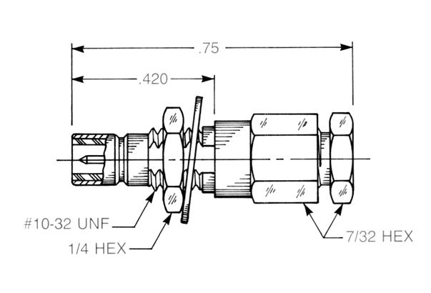
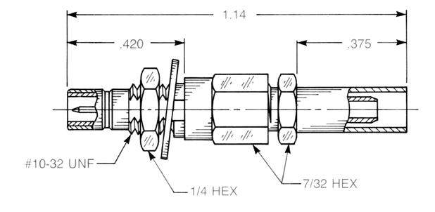
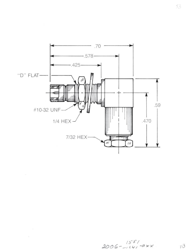
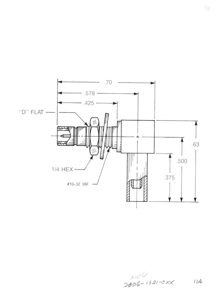
Straight Male Bulkhead Cable Jack
Clamp type for flexible cable: 2003-1551-0XX (Gold-plated) 2003-7551-0XX (Nickel-plated)
Solder-clamp for semi-rigid cable: 2003-1541-0XX (Gold-plated) 2003-7541-0XX (Nickel-plated)
Straight Male Bulkhead Cable Jack
Crimp type for flexible cable: 2003-1571-0XX (Gold-plated) 2003-7571-0XX (Nickel-plated)
Bulkhead Mounted Right Angle Male Cable Jack
Clamp type for flexible cable: 2006-1551-0XX (Gold-plated) 2006-7551-0XX (Nickel-plated)
Solder-clamp for semi-rigid cable: 2006-1541-0XX (Gold-plated) 2006-7541-0XX (Nickel-plated)
Bulkhead Mounted Right Angle Male Cable Jack
Crimp type for flexible cable: 2106-1521-0XX (Gold-plated) 2106-7521-0XX (Nickel-plated)
Substitute XX with the Appropriate Cable Group Below
02 RG178, RG196, M17/93, M17/169
03 RG174, RG179, RG316, M17/113, M17/119, M17/172, M17/173
05 RG178DS, RG196DS
09 0.141˝ semi-rigid, RG402, M17/130
10 0.085˝ semi-rigid, RG405, M17/133
19 RG174DS, RG316DS, M17/152, Times RD316
Designed for use with 0.093˝ max thick panel. See page 12-3 for D-flat location in relation to hex.
3-9 SMB
Go online for data sheets and assembly instructions. Visit www.radiall.com/AEP and enter the part number.
Simplification is Our Innovation.
Bulkhead Jacks
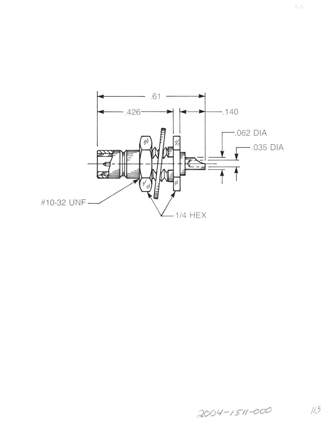
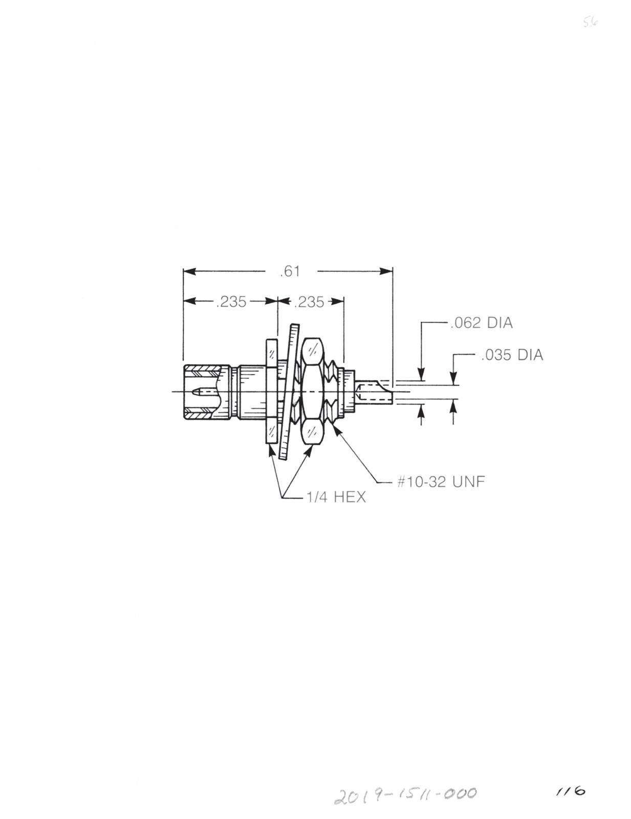
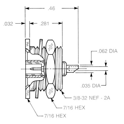
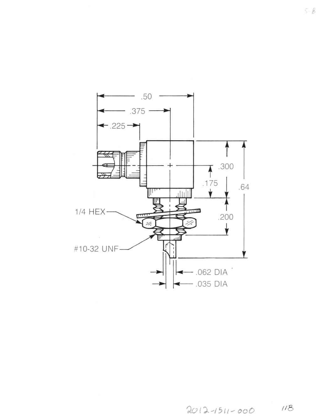
Straight Male Bulkhead Jack Receptacle
• Solder pot contact
• Rear mount
2004-1511-000 (Gold-plated) 2004-7511-000 (Nickel-plated)
Straight Male Bulkhead Jack Receptacle
• Solder pot contact
• Front mount
2019-1511-000 (Gold-plated) 2019-7511-000 (Nickel-plated)
Straight Male Bulkhead Jack Receptacle
• Solder pot contact
• Recessed front mount
2014-1511-000 (Gold-plated) 2014-7511-000 (Nickel-plated)
Straight Male Cable Jack
• Solder pot contact
• Front mount
2012-1511-000 (Gold-plated) 2012-7511-000 (Nickel-plated) Designed for use with 0.093˝ max thick panel. See page 12-3 for D-flat location in relation to hex.
3-10 SMB Visit www.radiall.com/AEP and enter the part number.
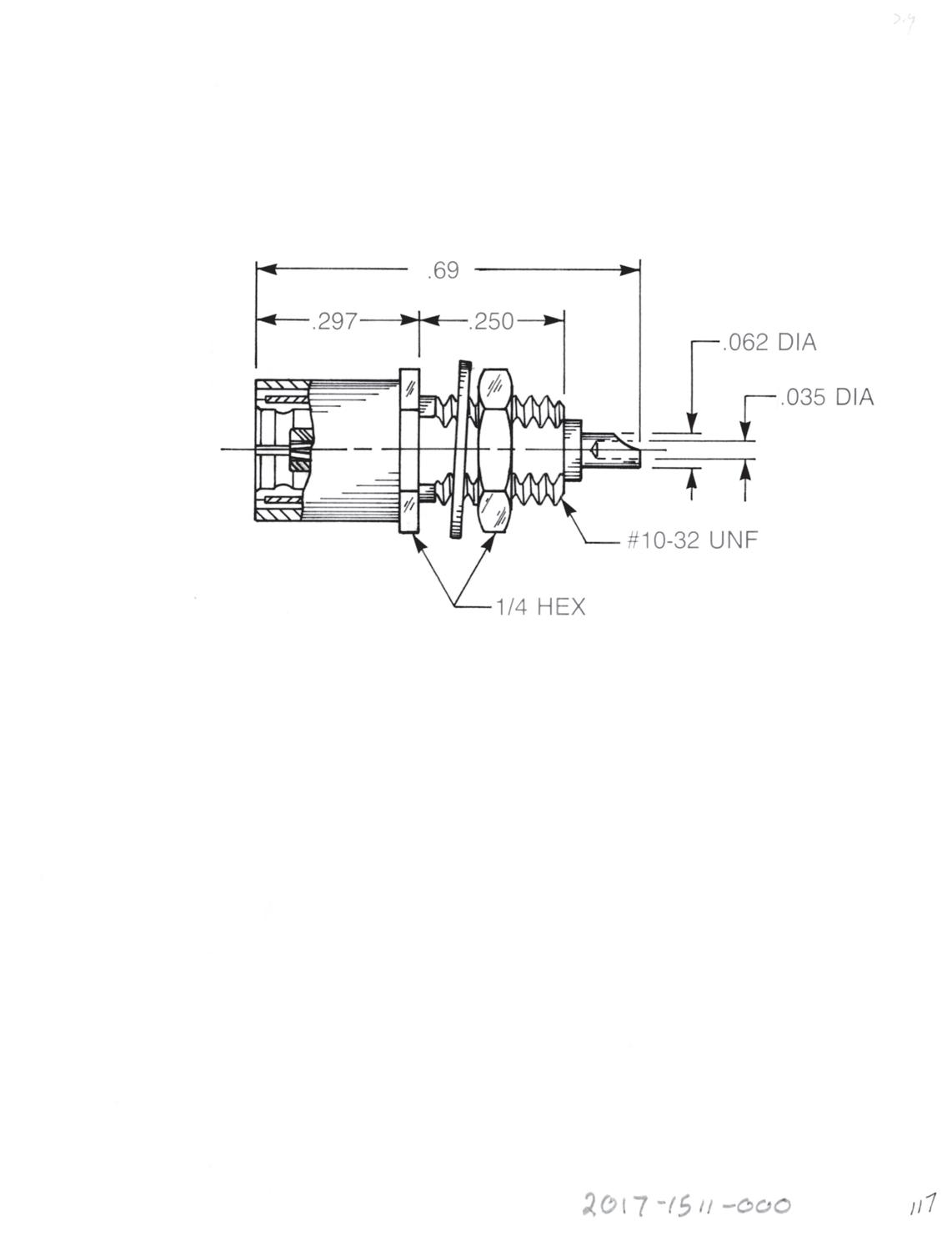
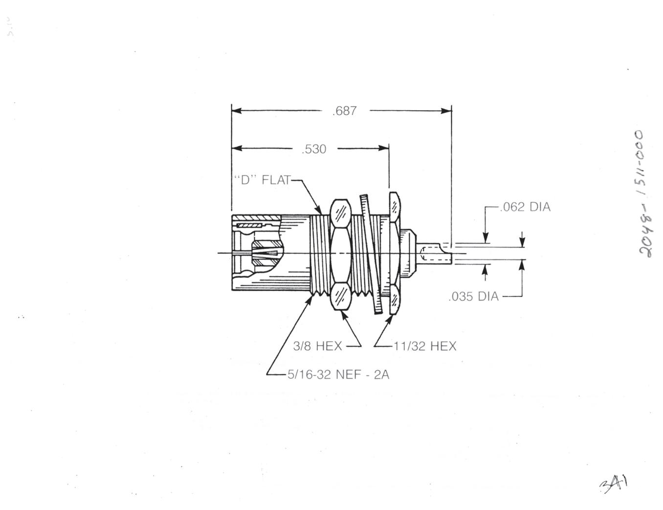
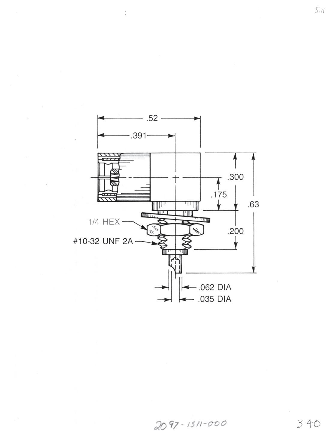
Straight Female Bulkhead Plug Receptacle
• Solder pot contact
• Front mount
2017-1511-000 (Gold-plated) 2017-7511-000 (Nickel-plated)
Straight Female Bulkhead Plug Receptacle
• Solder pot contact
• Rear mount
2048-1511-000 (Gold-plated)
2048-7511-000 (Nickel-plated)
Right Angle Female Bulkhead Plug Receptacle
• Solder pot contact
• Front mount
2097-1511-000 (Gold-plated)
2097-7511-000 (Nickel-plated)
Designed for use with 0.093˝ max thick panel.
3-11 SMB
Go online for data sheets and assembly instructions. Visit www.radiall.com/AEP and enter the part number.
Simplification is Our Innovation.

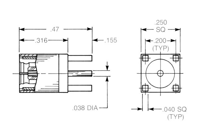
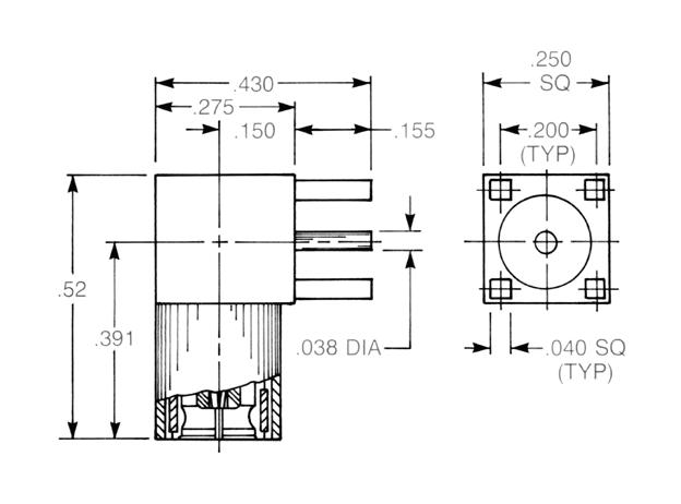
2042-1511-000 (Gold-plated)
2042-7511-000 (Nickel-plated)
3-12 Go online for data sheets and assembly instructions. Visit www.radiall.com/AEP and enter the part number.
Right Angle Female Plug Receptacle
Straight Male Jack Receptacle
PCB and Panel Receptacles
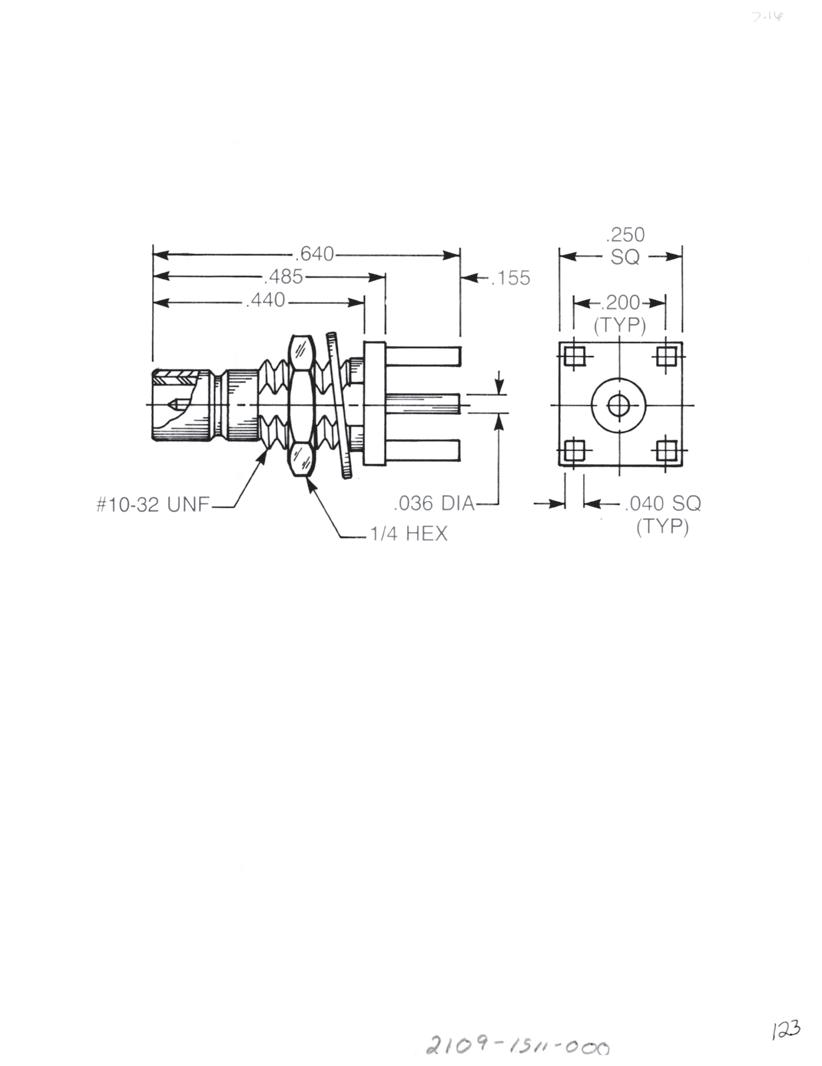
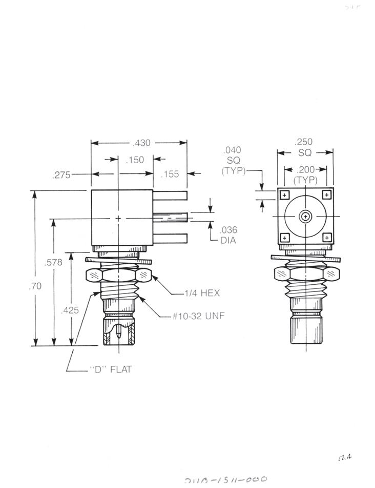
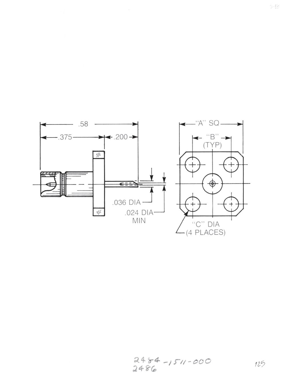
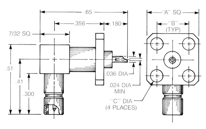
Simplification is Our Innovation.
Bulkhead Mounted Straight Male Jack PCB Receptacle
2109-1511-000 (Gold-plated)
2109-7511-000 (Nickel-plated)
Bulkhead Mounted Right Angle Male Jack PCB Receptacle
2110-1511-000 (Gold-plated)
2110-7511-000 (Nickel-plated)
Straight Male Panel Receptacle
A sq B C Ø
0.500 0.340 0.102
2486-1511-000 (Gold-plated)
2486-7511-000 (Nickel-plated)
A sq B C Ø
0.375 0.232 0.093
2484-1511-000 (Gold-plated)
2484-7511-000 (Nickel-plated)
Right Angle Male Panel Receptacle
A sq B C Ø
0.500 0.340 0.102
2490-1511-000 (Gold-plated)
2490-7511-000 (Nickel-plated)
A sq B C Ø
0.375 0.232 0.093
2488-1511-000 (Gold-plated)
2488-7511-000 (Nickel-plated)
3-13 SMB
Go online for data sheets and assembly instructions. Visit www.radiall.com/AEP and enter the part number.
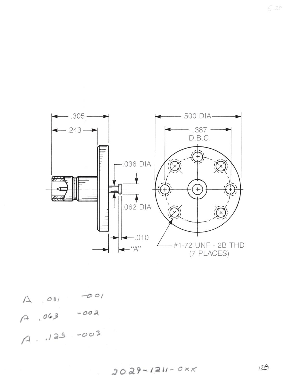
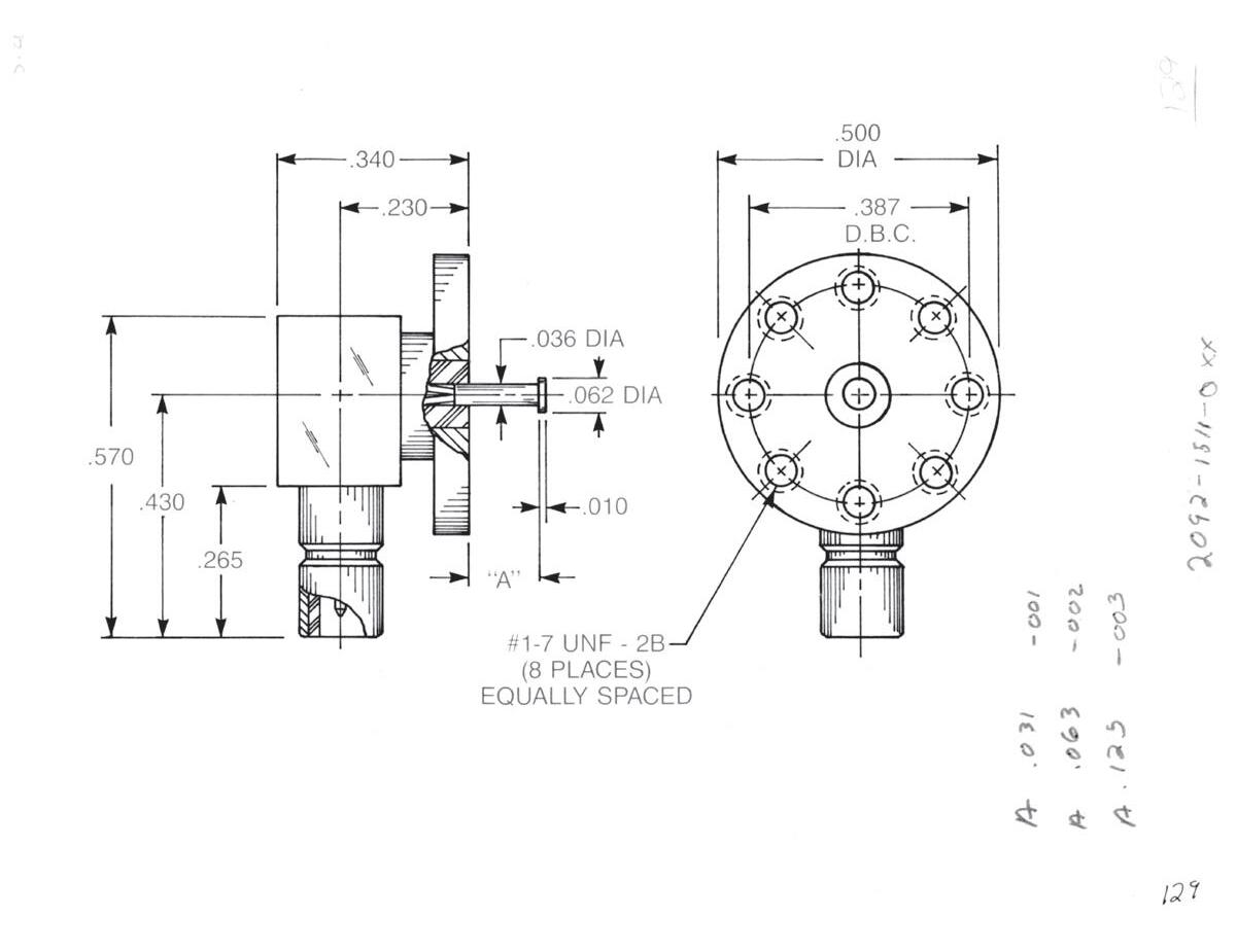
Straight Male Top Launch Jack
• Non-captive contact
Dim. A Part Number:
0.031 2029-1211-001 (Gold-plated)
2029-7211-001 (Nickel-plated)
0.063 2029-1211-002 (Gold-plated)
2029-7211-002 (Nickel-plated)
0.125 2029-1211-003 (Gold-plated)
2029-7211-003 (Nickel-plated)
Right Angle Male Top Launch Jack
• Removable rear contact
Dim. A Part Number:
0.031 2092-1511-001 (Gold-plated)
2092-7511-001 (Nickel-plated)
0.063 2092-1511-002 (Gold-plated) 2092-7511-002 (Nickel-plated)
0.125 2092-1511-003 (Gold-plated) 2092-7511-003 (Nickel-plated)
3-14 SMB Go online for data sheets and assembly instructions. Visit www.radiall.com/AEP and enter the part number.
Adapters Within Series
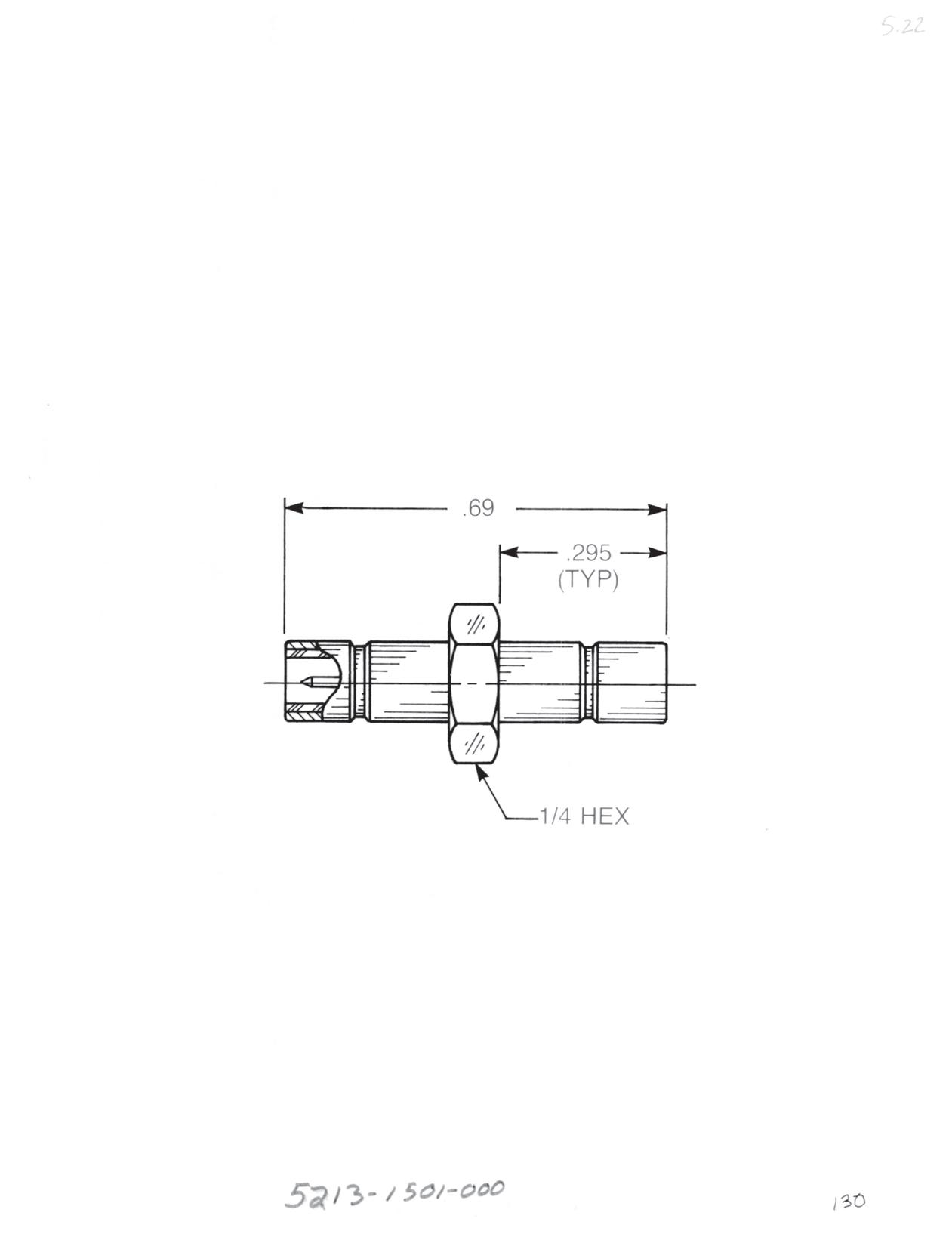
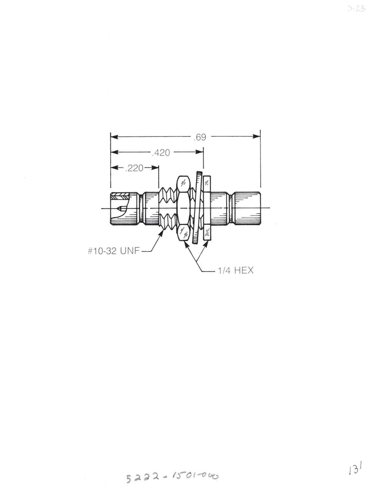
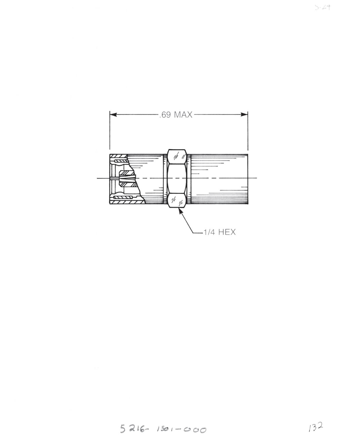
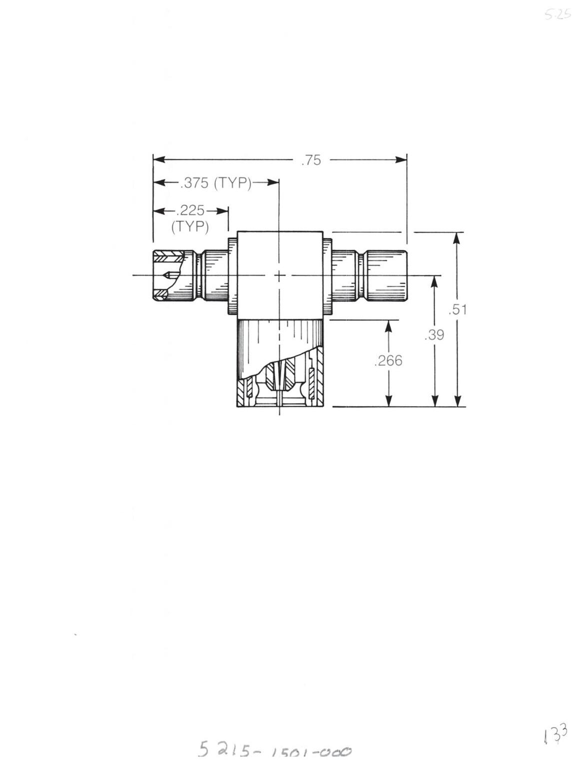
Straight Male Adapter
• Jack to jack
• Connects two plugs
5213-1501-000 (Gold-plated)
5213-7501-000 (Nickel-plated)
Bulkhead Mounted Straight Male Adapter
• Jack to jack
• Connects two plugs
• For 0.093˝ max panel
5222-1501-000 (Gold-plated)
5222-7501-000 (Nickel-plated)
Straight Female Adapter
• Plug to plug
• Connects two jacks
5216-1501-000 (Gold-plated)
5216-7501-000 (Nickel-plated)
Tee Adapter (Unmatched Power Divider)
• Jack to plug to jack
• Connects two plugs and one jack
5215-1501-000 (Gold-plated)
5215-7501-000 (Nickel-plated)
3-15 SMB Simplification
Visit www.radiall.com/AEP and enter the part number.
is Our Innovation.
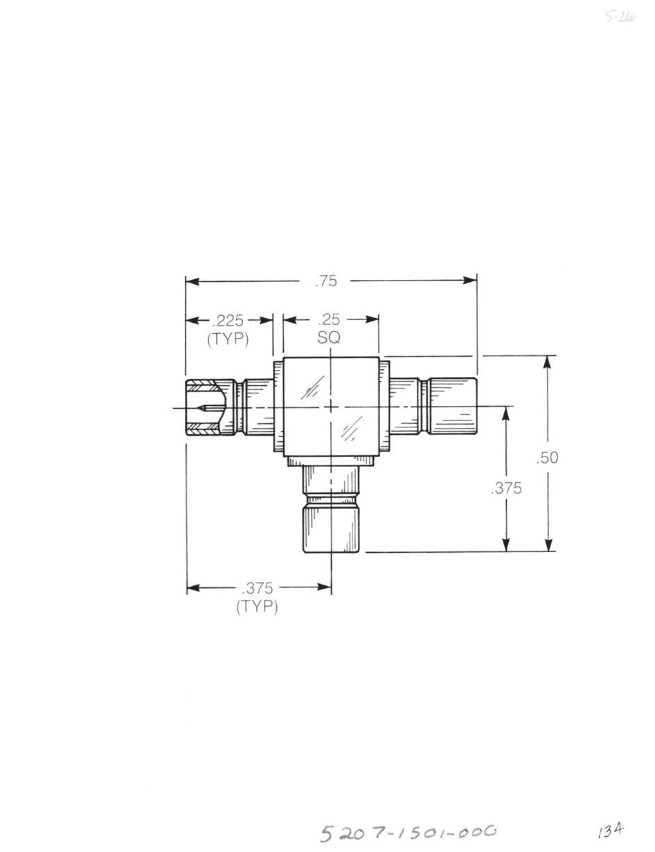
Adapters Within Series - Resistive Terminations
Tee Adapter (Unmatched Power Divider)
• Jack to jack to jack
• Connects three plugs
5207-1501-000 (Gold-plated)
5207-7501-000 (Nickel-plated)
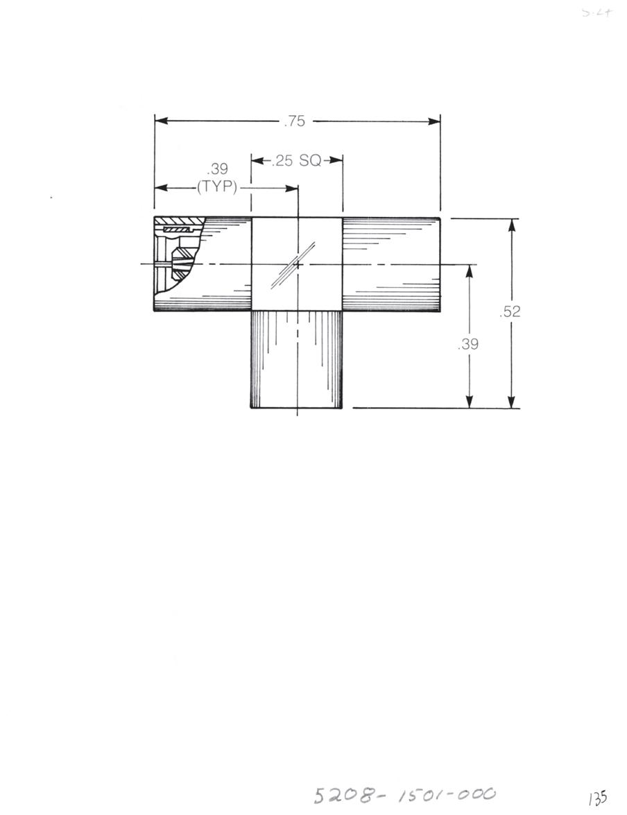
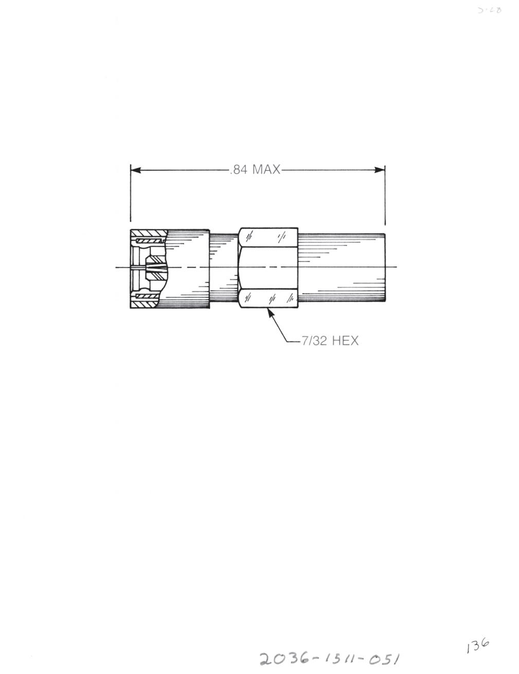
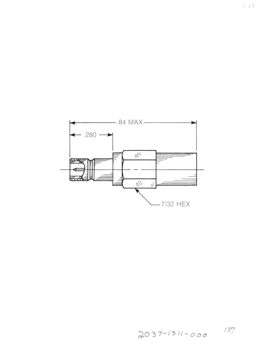
Tee Adapter (Unmatched Power Divider)
• Plug to plug to plug
• Connects three jacks
5208-1501-000 (Gold-plated)
5208-7501-000 (Nickel-plated)
Female Plug Resistive Termination (Dummy Load)
Standard resistor: 51 Ω, ½ W, 5% tolerance
2036-1511-051 (Gold-plated)
2036-7511-051 (Nickel-plated)
Available with other resistive values.
Male Jack Resistive Termination (Dummy Load)
Standard resistor: 51 Ω, ½ W, 5% tolerance
2037-1511-051 (Gold-plated)
2037-7511-051 (Nickel-plated)
Available with other resistive values.
3-16 Go online for data sheets and assembly instructions. Visit www.radiall.com/AEP and enter the part number.
Cable Plugs
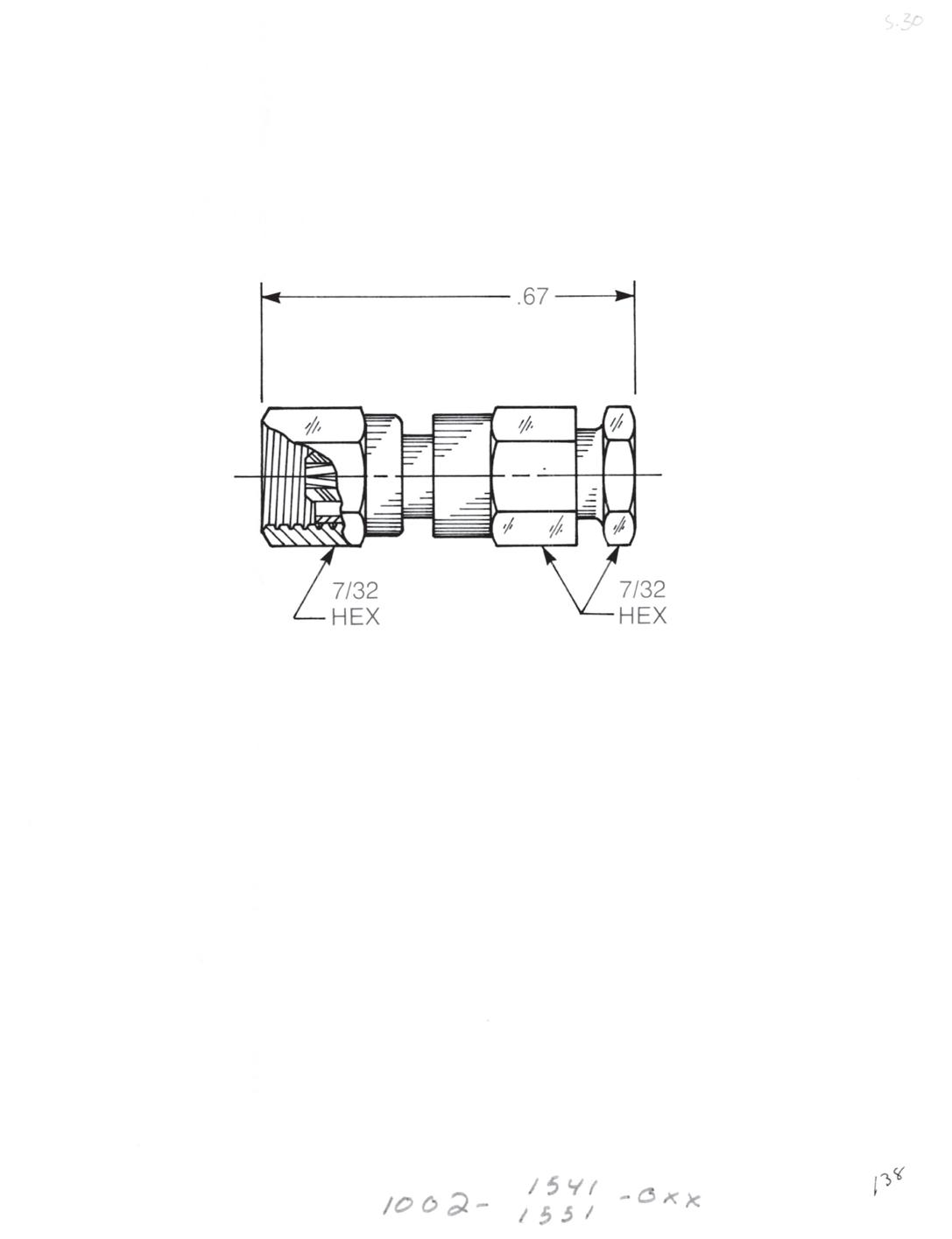
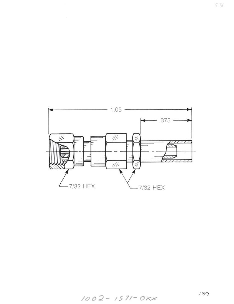
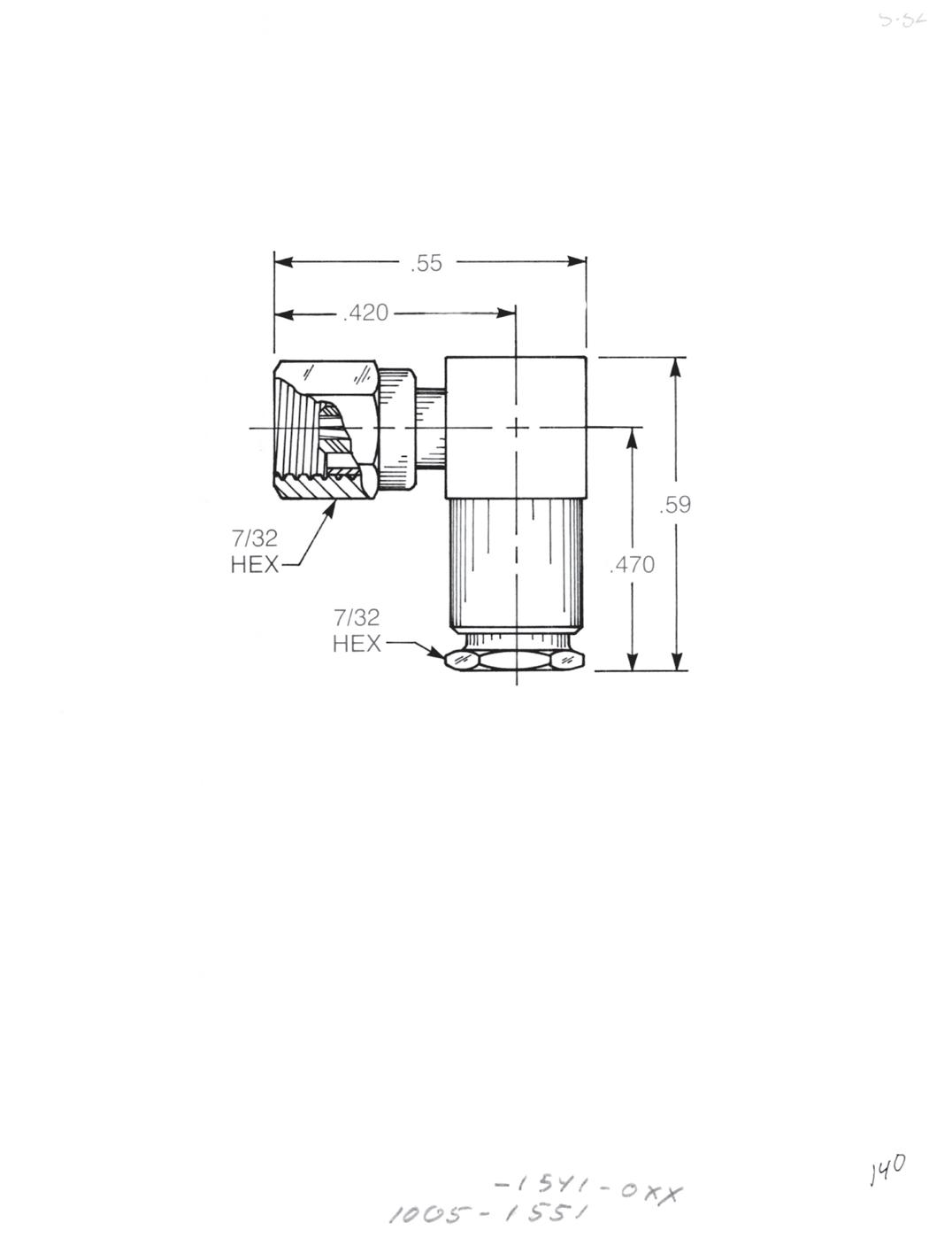
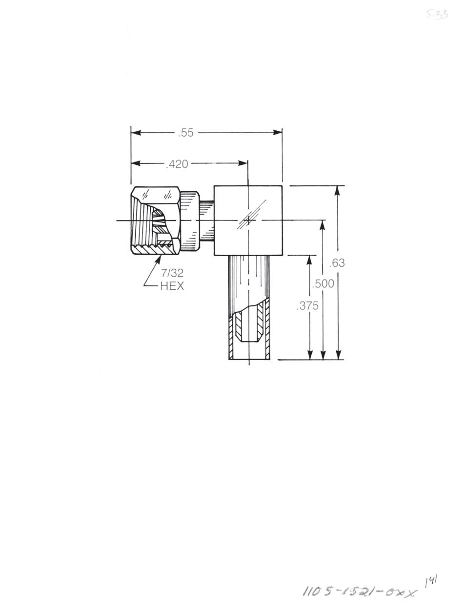
Straight Female Cable Plug
Clamp type for flexible cable: 1002-1551-0XX (Gold-plated)
1002-7551-0XX (Nickel-plated)
Solder-clamp for semi-rigid cable: 1002-1541-0XX (Gold-plated)
1002-7541-0XX (Nickel-plated)
Straight Female Cable Plug
Crimp type for flexible cable: 1002-1571-0XX (Gold-plated)
1002-7571-0XX (Nickel-plated)
Right Angle Female Cable Plug
Clamp type for flexible cable: 1005-1551-0XX (Gold-plated)
1005-7551-0XX (Nickel-plated)
Solder-clamp for semi-rigid cable: 1005-1541-0XX (Gold-plated)
1005-7541-0XX (Nickel-plated)
Right Angle Female Cable Plug
Clamp type for flexible cable: 1105-1521-0XX (Gold-plated)
1105-7521-0XX (Nickel-plated)
Substitute XX with the Appropriate Cable Group Below
02 RG178, RG196, M17/93, M17/169
03 RG174, RG179, RG316, M17/113, M17/119, M17/172, M17/173
05 RG178DS, RG196DS
09 0.141˝ semi-rigid, RG402, M17/130
10 0.085˝ semi-rigid, RG405, M17/133
19 RG174DS, RG316DS, M17/152, Times RD316
3-17 SMC Simplification
Go online for data sheets and assembly instructions. Visit www.radiall.com/AEP and enter the part number.
is Our Innovation.
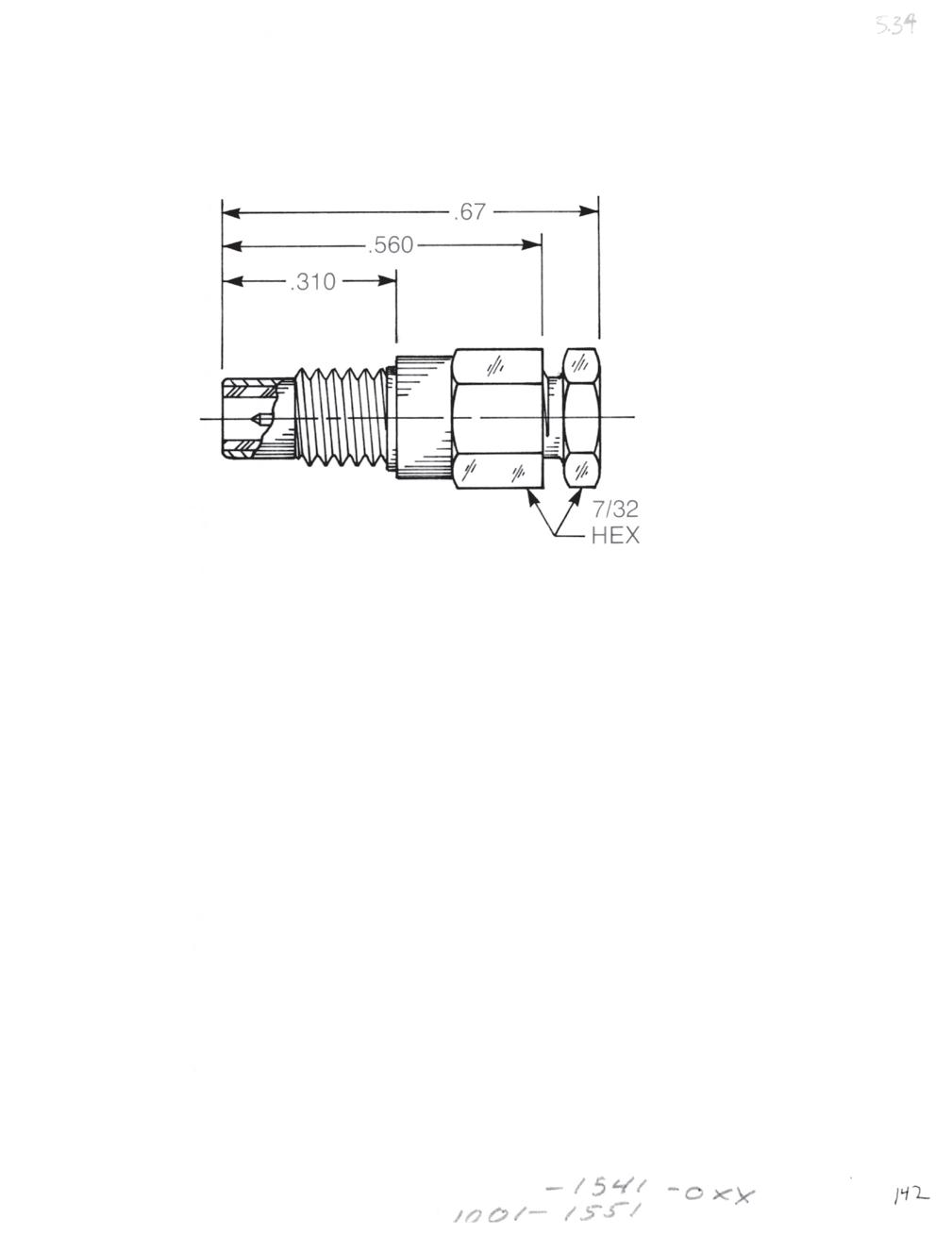
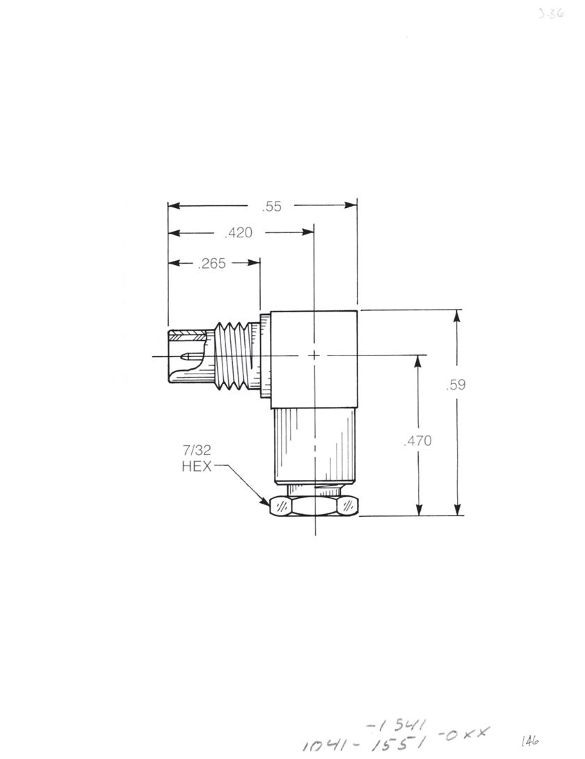
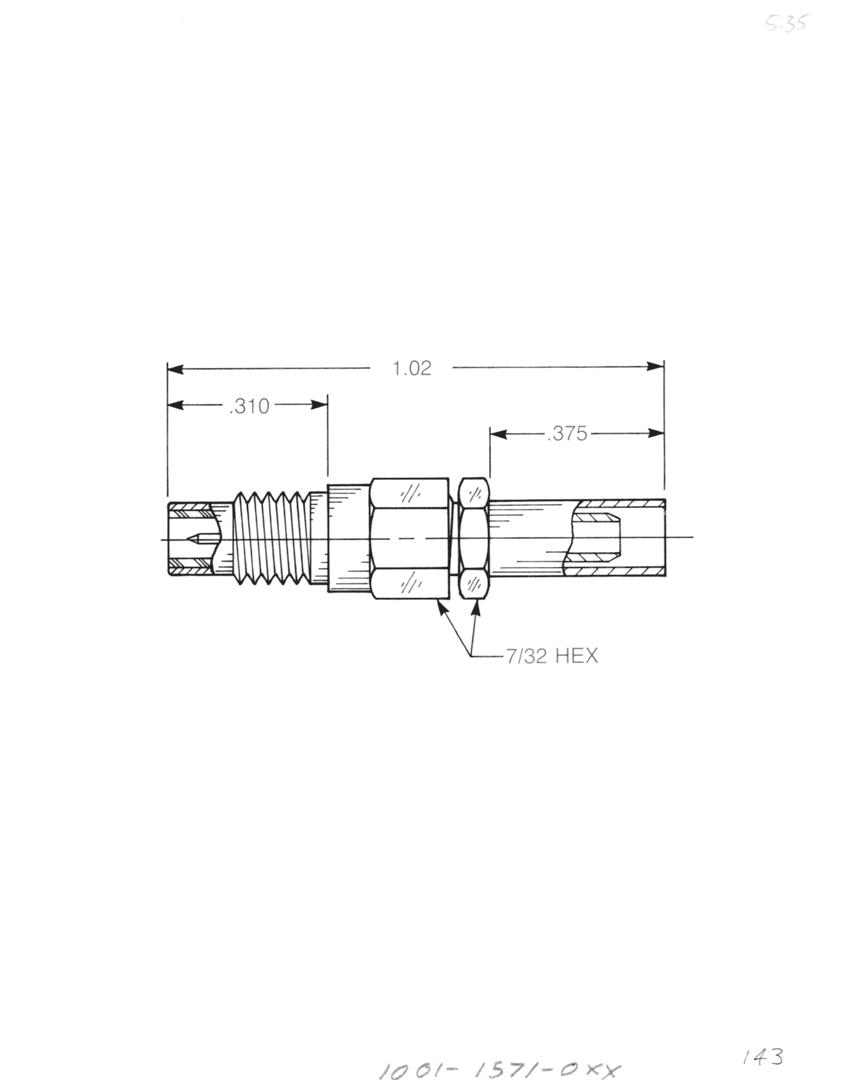
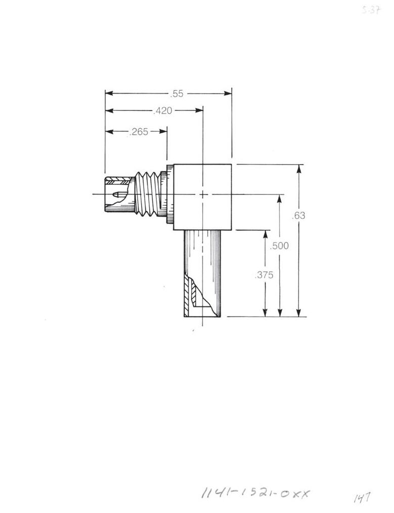
Straight Male Cable Jack
Clamp type for flexible cable: 1001-1551-0XX (Gold-plated) 1001-7551-0XX (Nickel-plated)
Solder-clamp for semi-rigid cable: 1001-1541-0XX (Gold-plated) 1001-7541-0XX (Nickel-plated)
Straight Male Cable Jack
Crimp type for flexible cable: 1001-1571-0XX (Gold-plated) 1001-7571-0XX (Nickel-plated)
Right Angle Male Cable Jack
Clamp type for flexible cable: 1041-1551-0XX (Gold-plated) 1041-7551-0XX (Nickel-plated)
Clamp type for flexible cable: 1141-1521-0XX (Gold-plated) 1141-7521-0XX (Nickel-plated) Cable Jacks
Solder-clamp for semi-rigid cable: 1041-1541-0XX (Gold-plated) 1041-7541-0XX (Nickel-plated)
Right Angle Male Cable Jack
Substitute XX with the Appropriate Cable Group Below
02 RG178, RG196, M17/93, M17/169
03 RG174, RG179, RG316, M17/113, M17/119, M17/172, M17/173
05 RG178DS, RG196DS
09 0.141˝ semi-rigid, RG402, M17/130
10 0.085˝ semi-rigid, RG405, M17/133
19 RG174DS, RG316DS, M17/152, Times RD316
3-18 SMC Go online for data sheets and assembly instructions. Visit www.radiall.com/AEP and enter the part number.
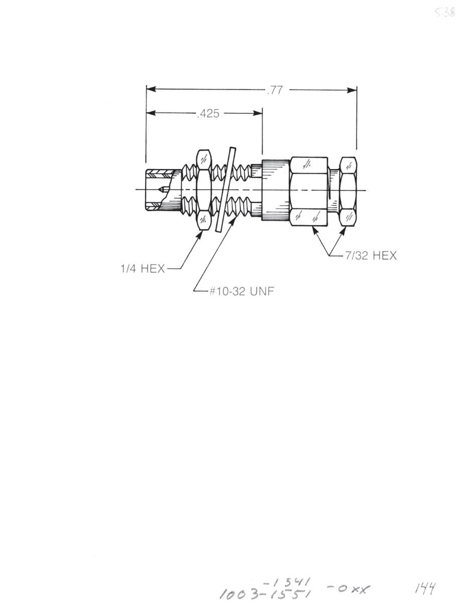
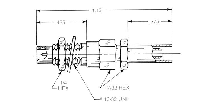
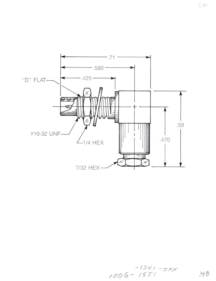

Straight Male Bulkhead Cable Jack
Clamp type for flexible cable:
1003-1551-0XX (Gold-plated)
1003-7551-0XX (Nickel-plated)
Solder-clamp for semi-rigid cable: 1003-1541-0XX (Gold-plated)
1003-7541-0XX (Nickel-plated)
Straight Male Bulkhead Cable Jack
Crimp type for flexible cable:
1003-1571-0XX (Gold-plated)
1003-7571-0XX (Nickel-plated)
Bulkhead Mounted Right Angle Male Cable Jack
Clamp type for flexible cable:
1006-1551-0XX (Gold-plated)
1006-7551-0XX (Nickel-plated)
Solder-clamp for semi-rigid cable: 1006-1541-0XX (Gold-plated) 1006-7541-0XX (Nickel-plated)
Bulkhead Mounted Right Angle Male Cable Jack
Crimp type for flexible cable: 1106-1521-0XX (Gold-plated)
1106-7521-0XX (Nickel-plated)
Substitute XX with the Appropriate Cable Group Below
02 RG178, RG196, M17/93, M17/169
03 RG174, RG179, RG316, M17/113, M17/119, M17/172, M17/173
05 RG178DS, RG196DS
09 0.141˝ semi-rigid, RG402, M17/130
10 0.085˝ semi-rigid, RG405, M17/133
19 RG174DS, RG316DS, M17/152, Times RD316
Designed for use with 0.093˝ max thick panel. See page 12-3 for D-flat location in relation to hex.
3-19 SMC
Go online for data sheets and assembly instructions. Visit www.radiall.com/AEP and enter the part number.
Simplification is Our Innovation.
Bulkhead Jacks

Straight Male Bulkhead Jack Receptacle
• Solder pot contact
• Rear mount
1004-1511-000 (Gold-plated)
1004-7511-000 (Nickel-plated)
Straight Male Bulkhead Jack Receptacle
• Solder pot contact
• Front mount
1019-1511-000 (Gold-plated)
1019-7511-000 (Nickel-plated)
Straight Female Bulkhead Plug Receptacle
• Solder pot contact
• Front mount
1017-1511-000 (Gold-plated)
1017-7511-000 (Nickel-plated)
Right Angle Male Bulkhead Jack Receptacle
• Solder pot contact
• Front mount
1012-1511-000 (Gold-plated)
1012-7511-000 (Nickel-plated)
Designed for use with 0.093˝ max thick panel. See page 12-3 for D-flat location in relation to hex.
3-20 Go online for data sheets and assembly instructions. Visit www.radiall.com/AEP and enter the part number.

Straight Male Jack Receptacle
1009-1511-000 (Gold-plated)
1009-7511-000 (Nickel-plated)
Right Angle Male Jack Receptacle
A B C D 0.43 0.15 0.55 0.42
1010-1511-000 (Gold-plated)
1010-7511-000 (Nickel-plated)
A B C D
0.50 0.215 0.55 0.42
1010-1511-001 (Gold-plated)
1010-7511-001 (Nickel-plated)
Straight Female Plug Receptacle
1025-1511-000 (Gold-plated)
1025-7511-000 (Nickel-plated)
Right Angle Female Plug Receptacle
1042-1511-000 (Gold-plated)
1042-7511-000 (Nickel-plated)
3-21 SMC
Go online for data sheets and assembly instructions. Visit www.radiall.com/AEP and enter the part number.
Simplification is Our Innovation.

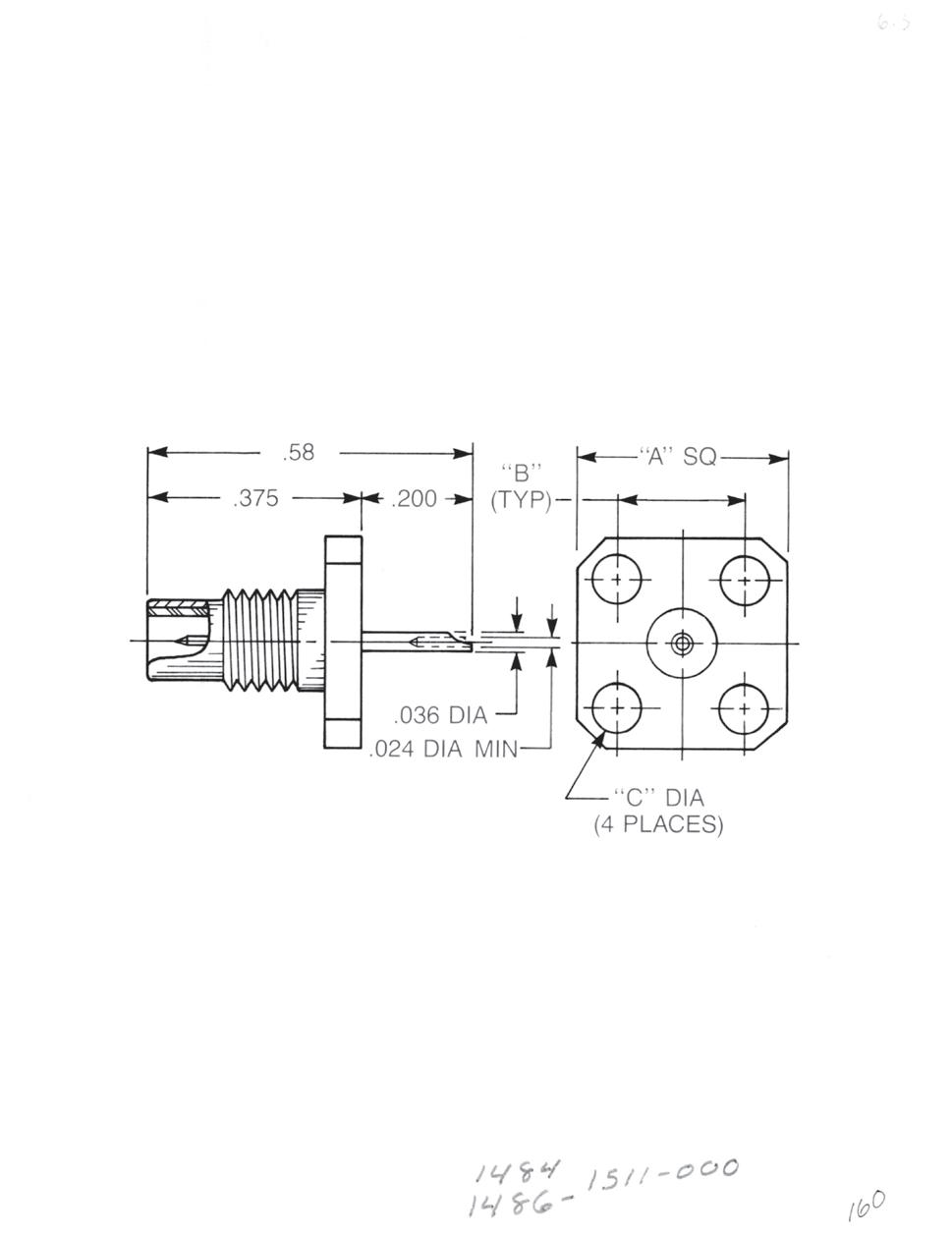
Bulkhead Mounted Straight Male Jack PCB Receptacle
1109-1511-000 (Gold-plated)
1109-7511-000 (Nickel-plated)
Bulkhead Mounted Right Angle Male Jack PCB Receptacle
1110-1511-000 (Gold-plated)
1110-7511-000 (Nickel-plated)
Straight Male Panel Receptacle
A sq B C Ø
0.500 0.340 0.102
1486-1511-000 (Gold-plated)
1486-7511-000 (Nickel-plated)
A sq B C Ø
0.375 0.232 0.093
1484-1511-000 (Gold-plated)
1484-7511-000 (Nickel-plated)
Right Angle Male Panel Receptacle
A sq B C Ø
0.500 0.340 0.102
1490-1511-000 (Gold-plated)
1490-7511-000 (Nickel-plated)
A sq B C Ø
0.375 0.232 0.093
1488-1511-000 (Gold-plated)
1488-7511-000 (Nickel-plated)
3-22 Go online for data sheets and assembly instructions. Visit www.radiall.com/AEP and enter the part number.
Stripline Receptacles
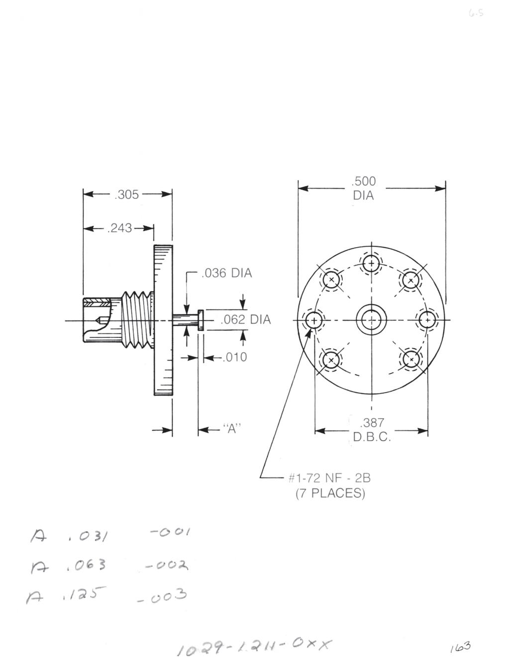
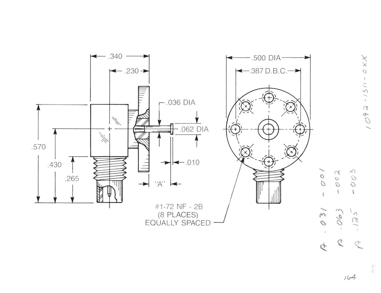
Straight Male Top Launch Jack • Non-captive contact
Dim. A Part Number:
0.031 1029-1211-001 (Gold-plated) 1029-7211-001 (Nickel-plated)
0.063 1029-1211-002 (Gold-plated) 1029-7211-002 (Nickel-plated)
0.125 1029-1211-003 (Gold-plated) 1029-7211-003 (Nickel-plated)
Right Angle Male Top Launch Jack • Removable rear contact
Dim. A Part Number:
0.031 1092-1511-001 (Gold-plated) 1092-7511-001 (Nickel-plated)
0.063 1092-1511-002 (Gold-plated) 1092-7511-002 (Nickel-plated)
0.125 1092-1511-003 (Gold-plated) 1092-7511-003 (Nickel-plated)
3-23 SMC Simplification
Go online for data sheets and assembly instructions. Visit www.radiall.com/AEP and enter the part number.
is Our Innovation.
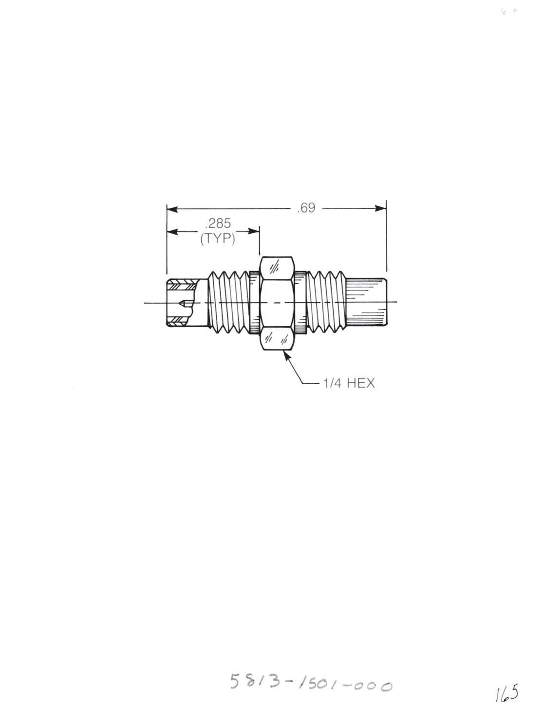
Adapters Within Series

Straight Male Adapter
• Jack to jack
• Connects two plugs
5813-1501-000 (Gold-plated)
5813-7501-000 (Nickel-plated)
Bulkhead Mounted Straight Male Adapter
• Jack to jack
• Connects two plugs
• For 0.093� max panel
5822-1501-000 (Gold-plated)
5822-7501-000 (Nickel-plated)
Straight Female Adapter
• Plug to plug
• Connects two jacks
5816-1501-000 (Gold-plated)
5816-7501-000 (Nickel-plated)
Tee Adapter (Unmatched Power Divider)
• Jack to plug to jack
• Connects two plugs and one jack
5815-1501-000 (Gold-plated)
5815-7501-000 (Nickel-plated)
3-24 Go online for data sheets and assembly instructions. Visit www.radiall.com/AEP and enter the part number.
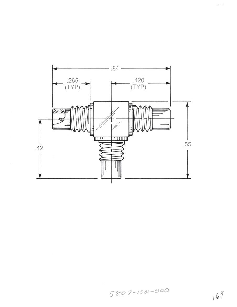
Adapters Within Series - Resistive Terminations
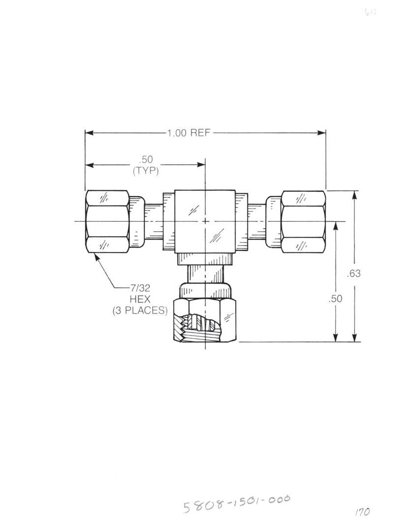
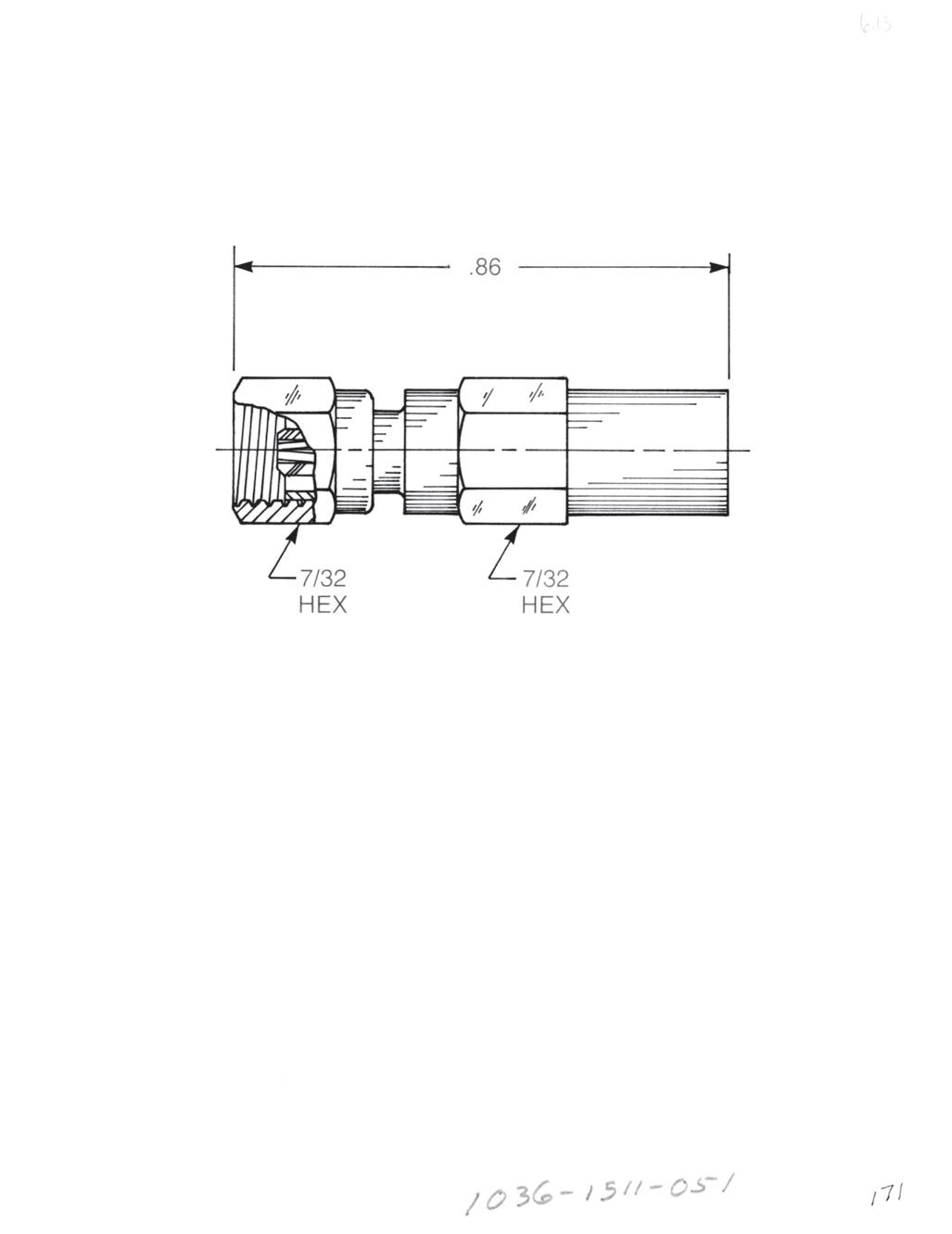
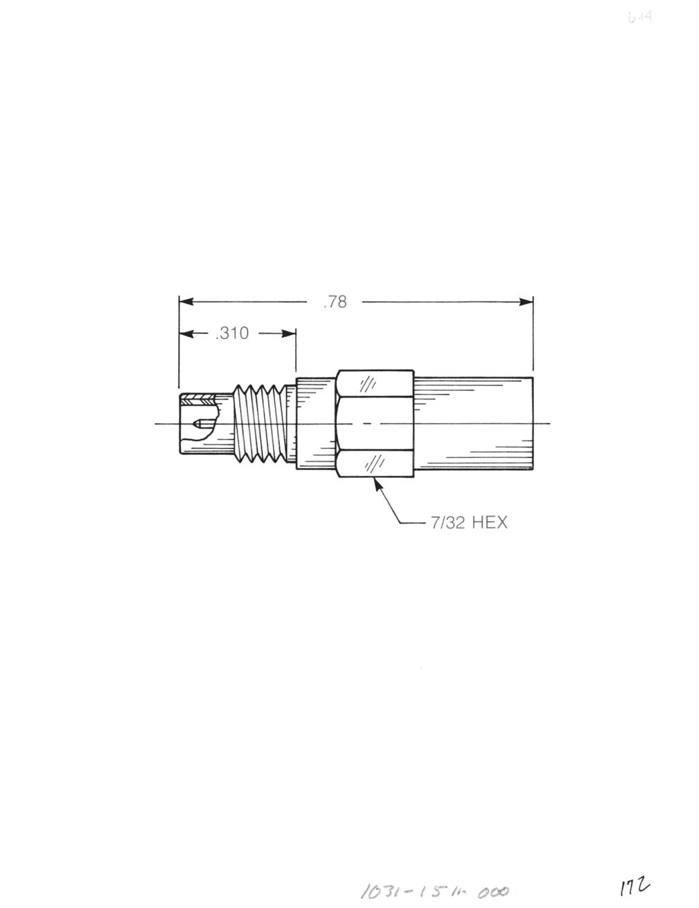
Tee Adapter (Unmatched Power Divider)
• Jack to jack to jack
• Connects three plugs
5807-1501-000 (Gold-plated)
5807-7501-000 (Nickel-plated)
Tee Adapter (Unmatched Power Divider)
• Plug to plug to plug
• Connects three jacks
5808-1501-000 (Gold-plated)
5808-7501-000 (Nickel-plated)
Female Plug Resistive Termination (Dummy Load)
Standard resistor: 51 Ω, ½ W, 5% tolerance
1036-1511-051 (Gold-plated) 1036-7511-051 (Nickel-plated)
Available with other resistive values.
Male Jack Resistive Termination (Dummy Load)
Standard resistor: 51 Ω, ½ W, 5% tolerance
1037-1511-051 (Gold-plated) 1037-7511-051 (Nickel-plated)
Available with other resistive values.
3-25 SMC Simplification
Go online for data sheets and assembly instructions. Visit www.radiall.com/AEP and enter the part number.
is Our Innovation.
Cable Plugs
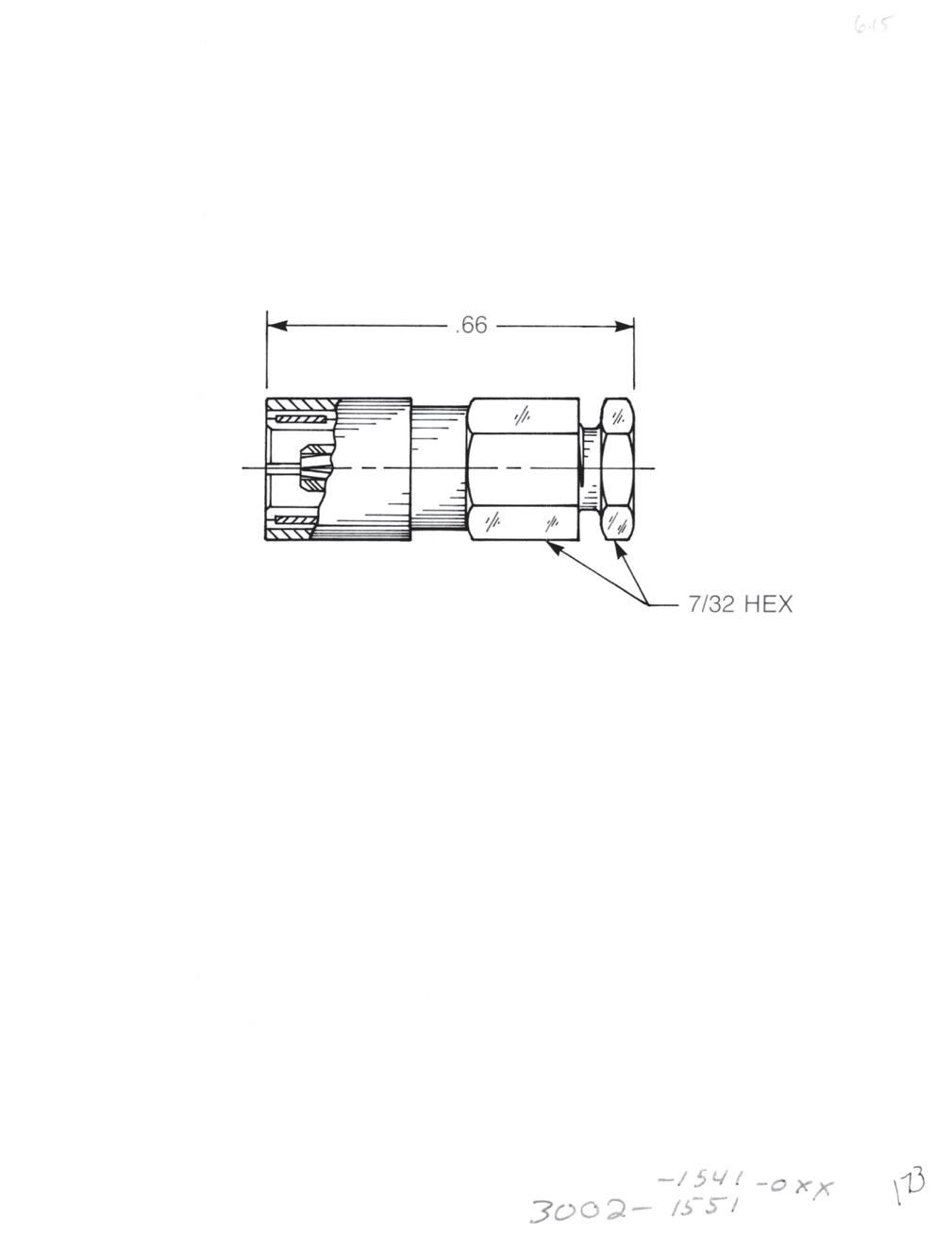
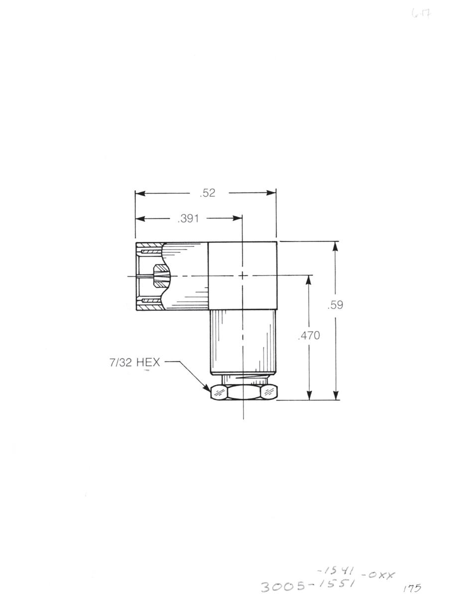
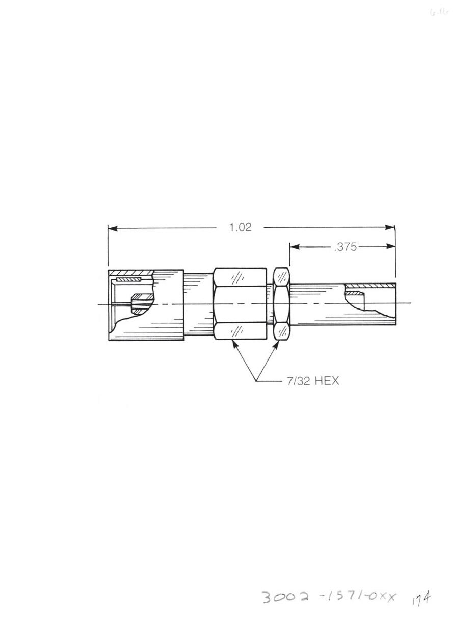
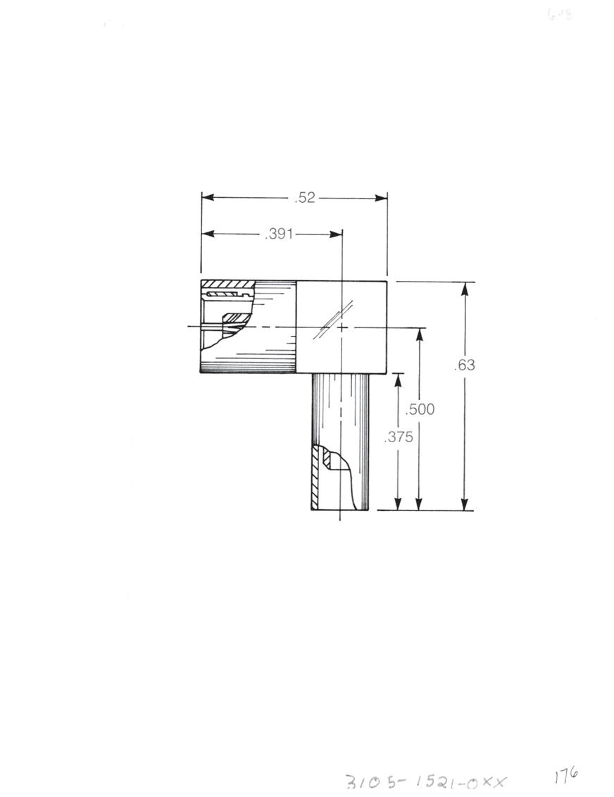
Straight Female Cable Plug
Clamp type for flexible cable:
3002-1551-0XX (Gold-plated)
3002-7551-0XX (Nickel-plated)
Solder-clamp for semi-rigid cable:
3002-1541-0XX (Gold-plated)
3002-7541-0XX (Nickel-plated)
Straight Female Cable Plug
Crimp type for flexible cable:
3002-1571-0XX (Gold-plated)
3002-7571-0XX (Nickel-plated)
Right Angle Female Cable Plug
Clamp type for flexible cable:
3005-1551-0XX (Gold-plated)
3005-7551-0XX (Nickel-plated)
Solder-clamp for semi-rigid cable:
3005-1541-0XX (Gold-plated)
3005-7541-0XX (Nickel-plated)
Right Angle Female Cable Plug
Crimp type for flexible cable:
3105-1521-0XX (Gold-plated)
3105-7521-0XX (Nickel-plated)
Substitute XX with the Appropriate Cable Group Below
02 RG178, RG196, M17/93, M17/169 09 0.141˝ semi-rigid, RG402, M17/130
03 RG174, RG179, RG316, M17/113, M17/119, M17/172, M17/173
05 RG178DS, RG196DS
10 0.085˝ semi-rigid, RG405, M17/133
19 RG174DS, RG316DS, M17/152, Times RD316
3-26 Go online for data sheets and assembly instructions. Visit www.radiall.com/AEP and enter the part number.
Bulkhead Mounted Cable Plugs
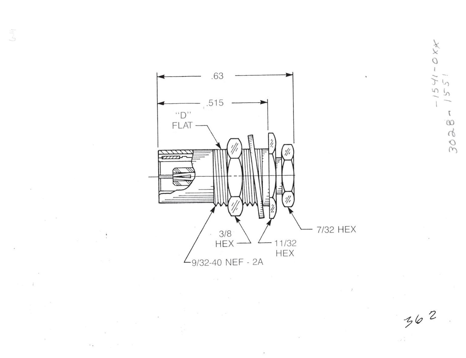
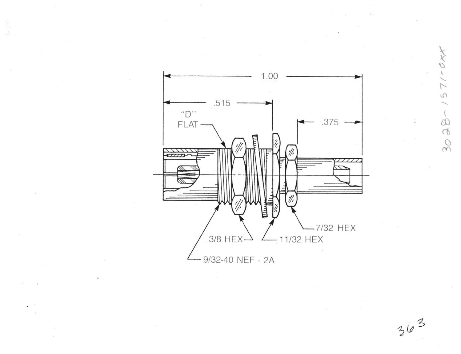
Bulkhead Mounted Straight Female Cable Plug
Clamp type for flexible cable: 3028-1551-0XX (Gold-plated)
3028-7551-0XX (Nickel-plated)
Solder-clamp for semi-rigid cable: 3028-1541-0XX (Gold-plated)
3028-7541-0XX (Nickel-plated)
See page 3-35 for float mount version.
Bulkhead Mounted Straight Female Cable Plug
Crimp type for flexible cable:
3028-1571-0XX (Gold-plated)
3028-7571-0XX (Nickel-plated)
See page 3-35 for float mount version.
Substitute XX with the Appropriate Cable Group Below
02 RG178, RG196, M17/93, M17/169
03 RG174, RG179, RG316, M17/113, M17/119, M17/172, M17/173
05 RG178DS, RG196DS
09 0.141˝ semi-rigid, RG402, M17/130
10 0.085˝ semi-rigid, RG405, M17/133
19 RG174DS, RG316DS, M17/152, Times RD316
Designed for use with 0.093˝ max thick panel.
3-27 SLB
Go online for data sheets and assembly instructions. Visit www.radiall.com/AEP and enter the part number.
Simplification is Our Innovation.
Cable Jacks
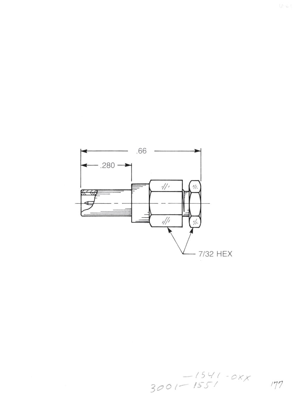
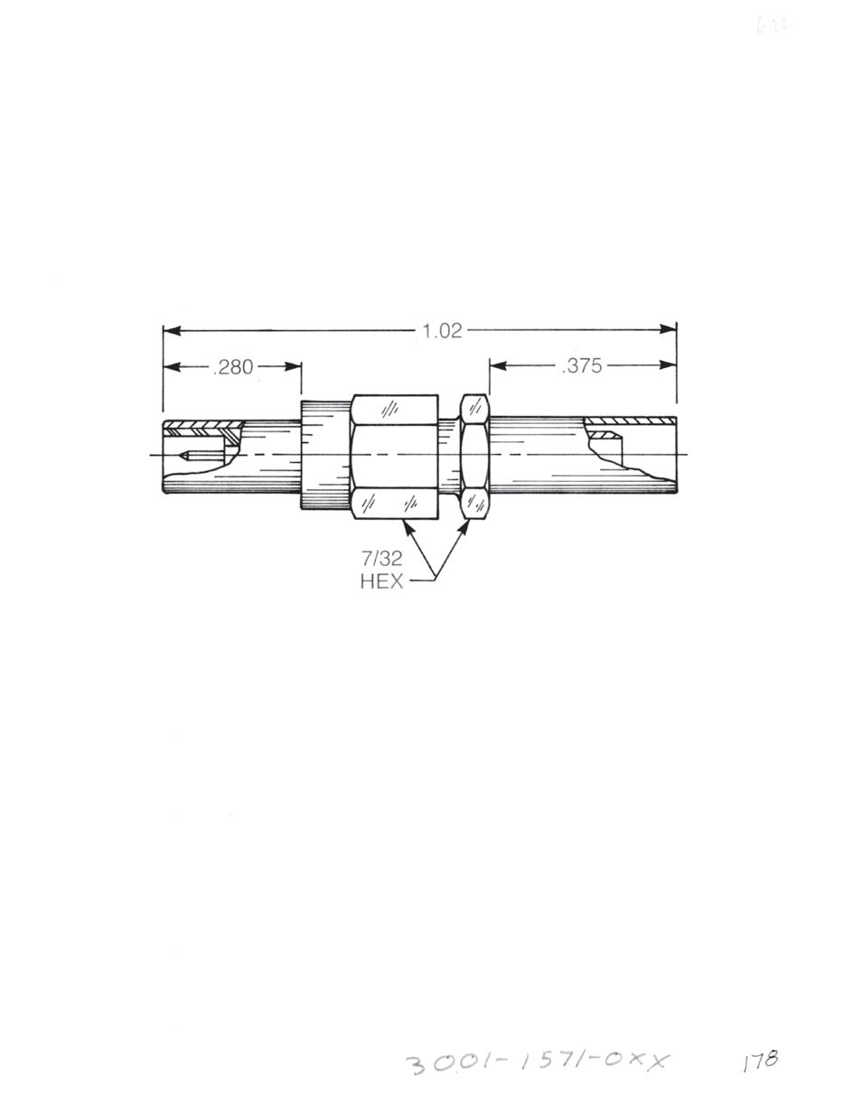
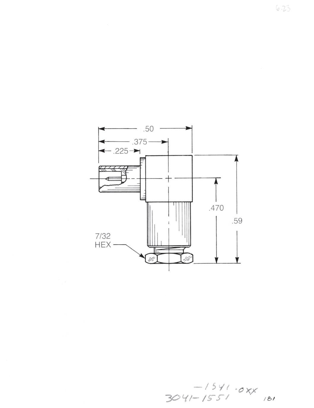
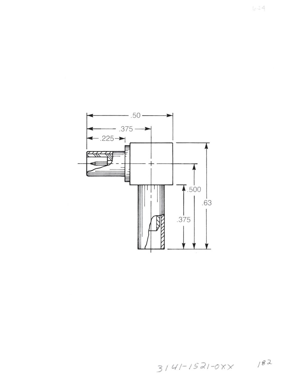
Straight Male Cable Jack
Clamp type for flexible cable:
3001-1551-0XX (Gold-plated)
3001-7551-0XX (Nickel-plated)
Solder-clamp for semi-rigid cable: 3001-1541-0XX (Gold-plated)
3001-7541-0XX (Nickel-plated)
Straight Male Cable Jack
Crimp type for flexible cable: 3001-1571-0XX (Gold-plated)
3001-7571-0XX (Nickel-plated)
Right Angle Male Cable Jack
Clamp type for flexible cable: 3041-1551-0XX (Gold-plated)
3041-7551-0XX (Nickel-plated)
Solder-clamp for semi-rigid cable: 3041-1541-0XX (Gold-plated)
3041-7541-0XX (Nickel-plated)
Right Angle Male Cable Jack
Crimp type for flexible cable: 3141-1571-0XX (Gold-plated)
3141-7571-0XX (Nickel-plated)
Substitute XX with the Appropriate Cable Group Below
02 RG178, RG196, M17/93, M17/169
03 RG174, RG179, RG316, M17/113, M17/119, M17/172, M17/173
05 RG178DS, RG196DS
09 0.141˝ semi-rigid, RG402, M17/130
10 0.085˝ semi-rigid, RG405, M17/133
19 RG174DS, RG316DS, M17/152, Times RD316
3-28 Go online for data sheets and assembly instructions. Visit www.radiall.com/AEP and enter the part number.
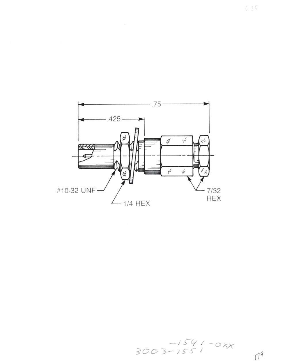
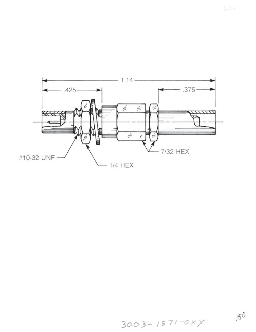
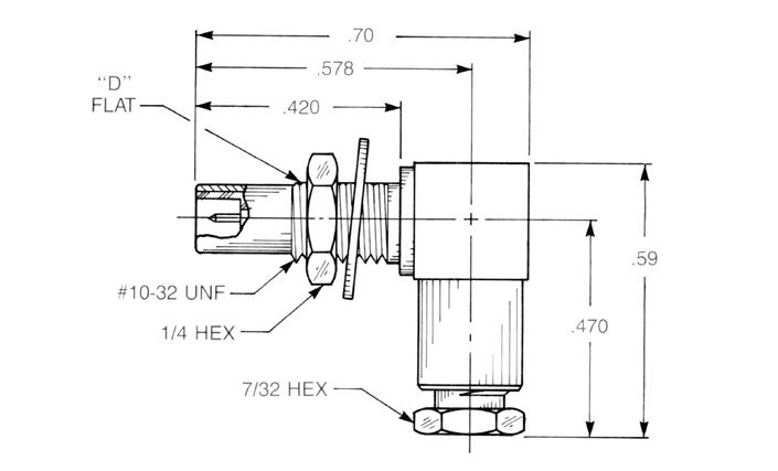
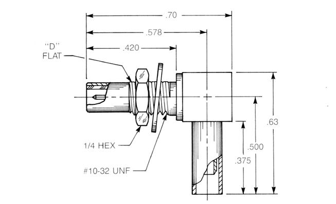
Straight Male Bulkhead Cable Jack
Clamp type for flexible cable:
3003-1551-0XX (Gold-plated)
3003-7551-0XX (Nickel-plated)
Solder-clamp for semi-rigid cable:
3003-1541-0XX (Gold-plated)
3003-7541-0XX (Nickel-plated)
See page 3-36 for float mount version.
Straight Male Bulkhead Cable Jack
Crimp type for flexible cable:
3003-1571-0XX (Gold-plated)
3003-7571-0XX (Nickel-plated)
See page 3-36 for float mount version.
Right Angle Male Bulkhead Cable Jack
Clamp type for flexible cable:
3006-1551-0XX (Gold-plated)
3006-7551-0XX (Nickel-plated)
Solder-clamp for semi-rigid cable:
3006-1541-0XX (Gold-plated)
3006-7541-0XX (Nickel-plated)
See page 3-37 for float mount version.
Right Angle Male Bulkhead Cable Jack
Crimp type for flexible cable:
3106-1521-0XX (Gold-plated)
3106-7521-0XX (Nickel-plated)
See page 3-37 for float mount version.
Substitute XX with the Appropriate Cable Group Below 02 RG178, RG196, M17/93, M17/169 09 0.141˝ semi-rigid, RG402, M17/130 03 RG174, RG179, RG316, M17/113, M17/119, M17/172, M17/173
05
RG178DS, RG196DS
10 0.085˝ semi-rigid, RG405, M17/133
19 RG174DS, RG316DS, M17/152, Times RD316
Designed for use with 0.093˝ max thick panel. See page 12-3 for D-flat location in relation to hex.
3-29 SLB Simplification
Go online for data sheets and assembly instructions. Visit www.radiall.com/AEP and enter the part number.
is Our Innovation.
Bulkhead Jacks
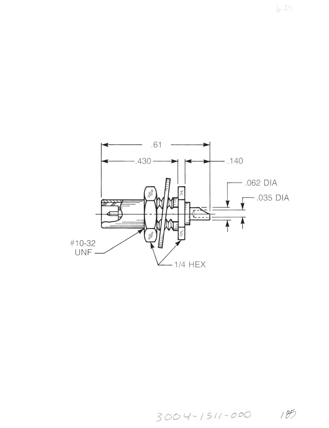
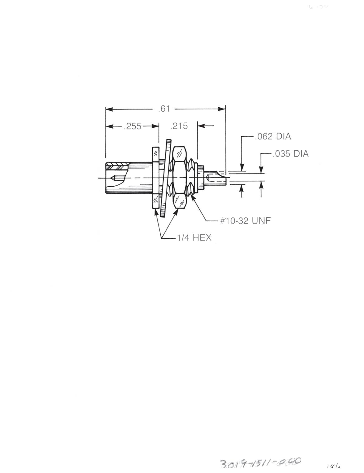
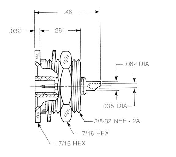
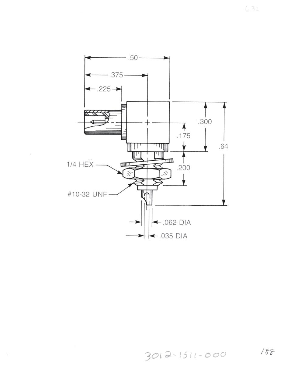
Straight Male Bulkhead Jack Receptacle
• Solder pot contact
• Rear mount
3004-1511-000 (Gold-plated)
3004-7511-000 (Nickel-plated)
See page 3-38 for float mount version.
Straight Male Bulkhead Jack Receptacle
• Solder pot contact
• Front mount
3019-1511-000 (Gold-plated)
3019-7511-000 (Nickel-plated)
See page 3-38 for float mount version.
Straight Male Bulkhead Jack Receptacle
• Solder pot contact
• Recessed front mount
3014-1511-000 (Gold-plated)
3014-7511-000 (Nickel-plated)
See page 3-38 for float mount version.
Right Angle Male Bulkhead Jack Receptacle
• Solder pot contact
• Front mount
3012-1511-000 (Gold-plated)
3012-7511-000 (Nickel-plated)
Designed for use with 0.093˝ max thick panel. See page 12-3 for D-flat location in relation to hex.
Go online for data sheets and assembly instructions. Visit www.radiall.com/AEP and enter the part number.
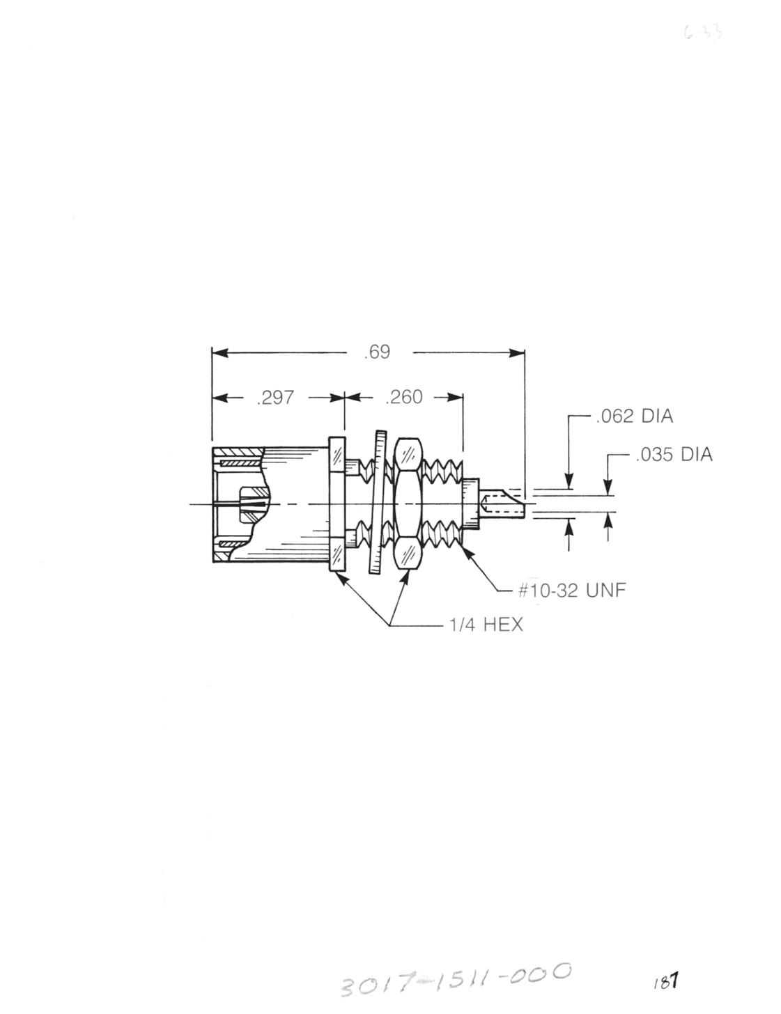
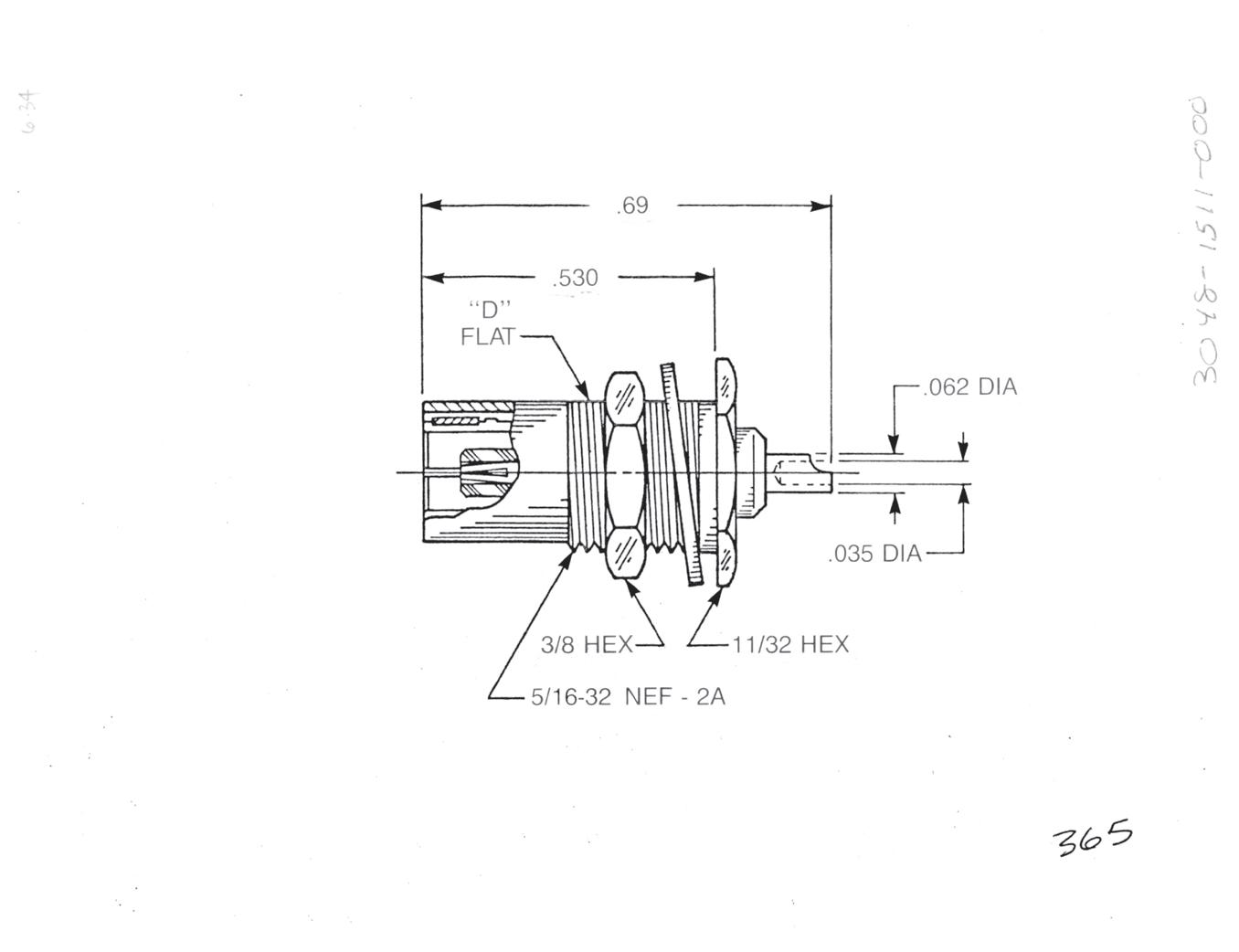
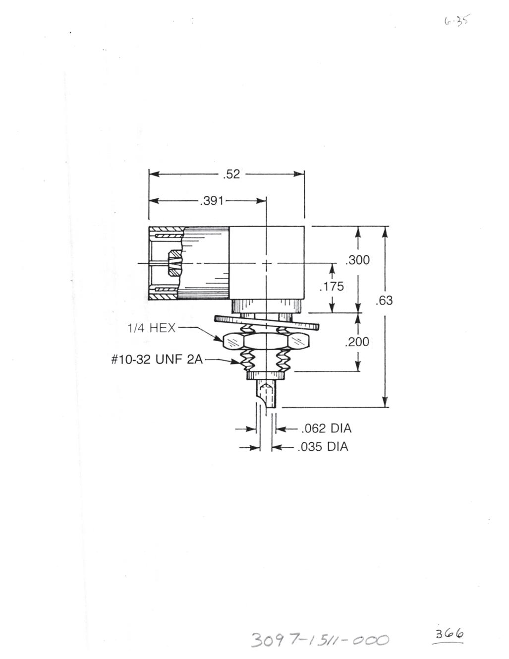
Straight Female Bulkhead Plug Receptacle
• Solder pot contact
• Front mount
3017-1511-000 (Gold-plated)
3017-7511-000 (Nickel-plated)
See page 3-39 for float mount version.
Straight Female Bulkhead Plug Receptacle
• Solder pot contact
• Rear mount
3048-1511-000 (Gold-plated)
3048-7511-000 (Nickel-plated)
See page 3-39 for float mount version.
Right Angle Female Bulkhead Plug Receptacle
• Solder pot contact
• Front mount
3097-1511-000 (Gold-plated)
3097-7511-000 (Nickel-plated)
Designed for use with 0.093˝ max thick panel.
3-31 SLB Simplification
Go online for data sheets and assembly instructions. Visit www.radiall.com/AEP and enter the part number.
is Our Innovation.

PCB Receptacles
Straight Male Jack Receptacle
3009-1511-000 (Gold-plated)
3009-7511-000 (Nickel-plated)
Right Angle Male Jack Receptacle
A B C D
0.43 0.15 0.50 0.38
3010-1511-000 (Gold-plated)
3010-7511-000 (Nickel-plated)
A B C D
0.50 0.215 0.56 0.437
3010-1511-003 (Gold-plated)
3010-7511-003 (Nickel-plated)
Straight Female Plug Receptacle
3025-1511-000 (Gold-plated)
3025-7511-000 (Nickel-plated)
See page 3-40 for blind mate version.
Right Angle Female Plug Receptacle
3042-1511-000 (Gold-plated)
3042-7511-000 (Nickel-plated)
See page 3-40 for blind mate version.
3-32 Go online for data sheets and assembly instructions. Visit www.radiall.com/AEP and enter the part number.
PCB Receptacles - Adapter
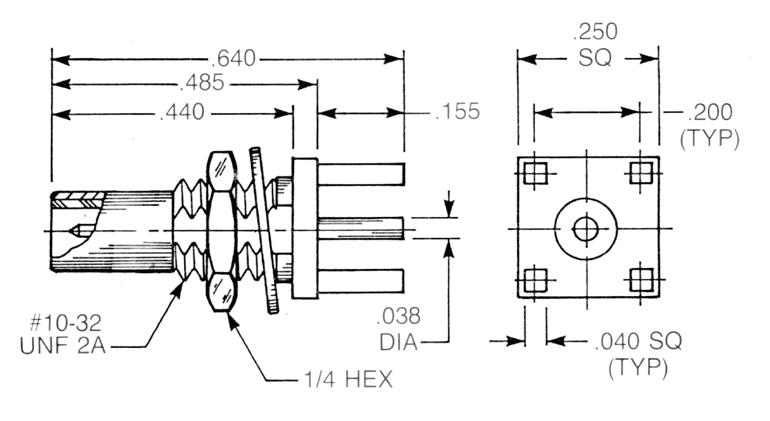
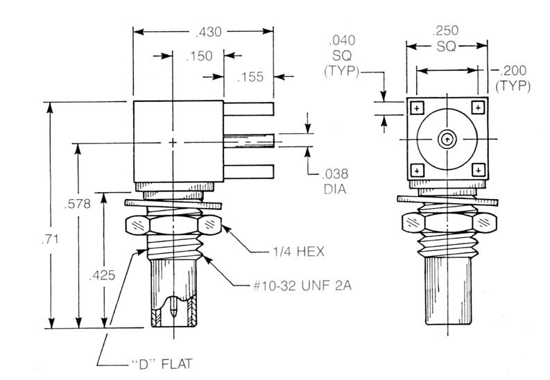
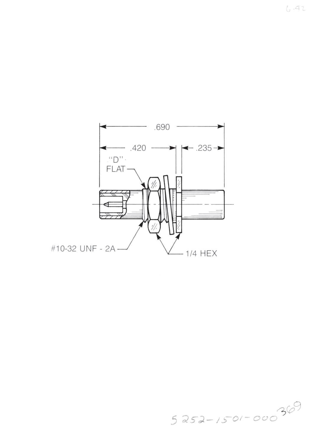
Bulkhead Mounted Straight Male Jack PCB Receptacle
3109-1511-000 (Gold-plated)
3109-7511-000 (Nickel-plated)
See page 3-40 for float mount version.
Bulkhead Mounted Right Angle Male Jack PCB Receptacle
3110-1511-000 (Gold-plated)
3110-7511-000 (Nickel-plated)
See page 3-40 for float mount version.
Bulkhead Mounted Straight Male • Jack to jack adapter
5252-1501-000 (Gold-plated)
5252-7501-000 (Nickel-plated)
See page 3-39 for float mount version.
Designed for use with 0.093˝ max thick panel.
3-33 SLB
Go online for data sheets and assembly instructions. Visit www.radiall.com/AEP and enter the part number.
Simplification is Our Innovation.
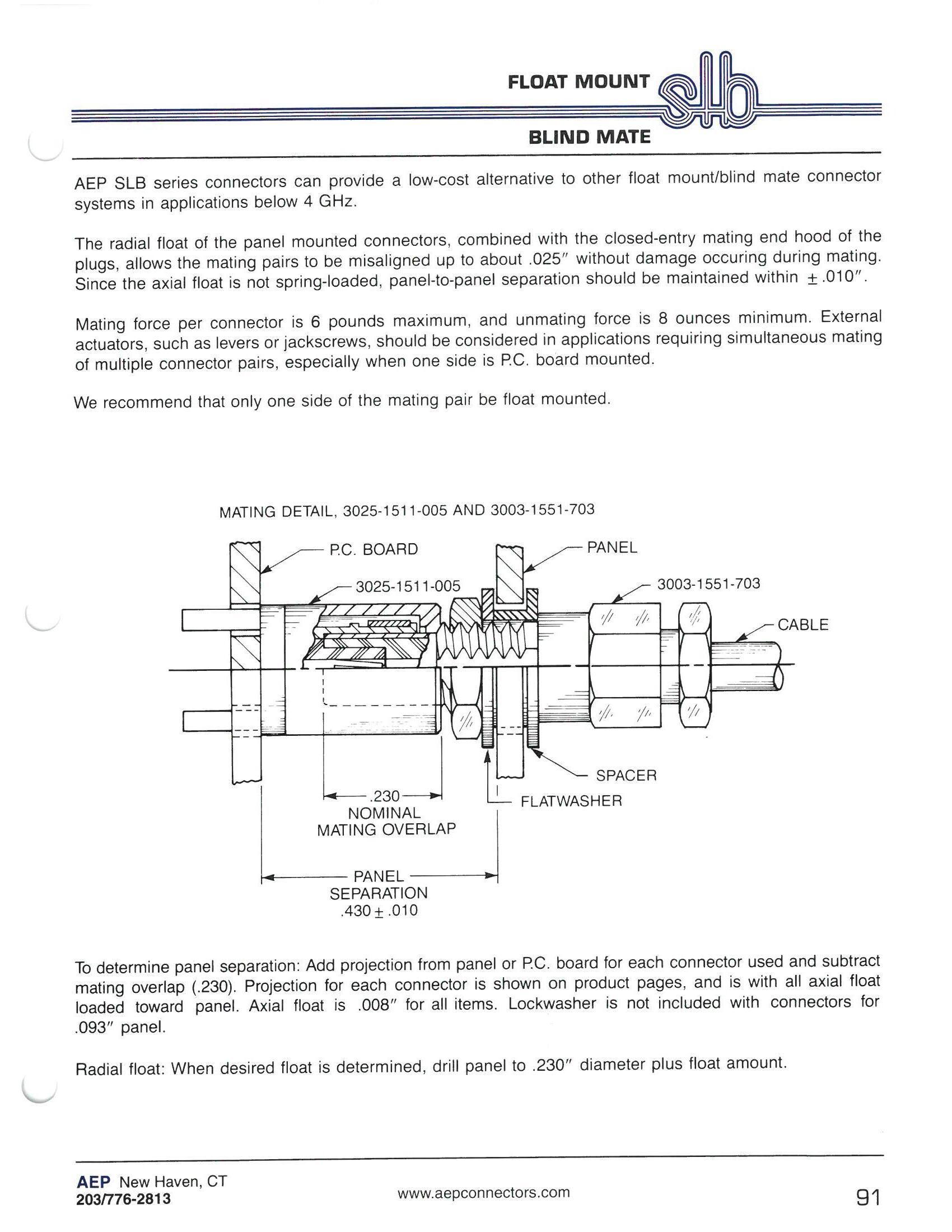
AEP SLB series connectors can provide a low-cost alternative to other float mount/blind mate connector
The radial float of the panel mounted connectors, combined with the closed-entry mating end hood of the plugs, allows the mating pairs to be misaligned up to about 0.025˝ without damage occuring during mating. Since the axial float is not spring-loaded, panel-to-panel separation should be maintained within ± 0.010˝.
Mating force per connector is 6 pounds maximum, and unmating force is 8 ounces minimum. External actuators, such as levers or jackscrews, should be considered in applications requiring simultaneous
subtract mating overlap (0.230�). Projection for each connector is shown on product pages, and is with all axial float loaded toward panel. Axial float is 0.008˝ for all items. Lockwasher is not included with
3-34 Go online for data sheets and assembly instructions. Visit www.radiall.com/AEP and enter the part number.
Cable Plugs - Float Mount/Blind Mate

Bulkhead Mounted Straight Female Cable Plug Float Mount/Blind Mate
• Closed-entry mating end hood
Dim. A Dim. B Clamp type for flexible cable:
0.031 0.500 3028-1551-5XX (Gold-plated)
3028-7551-5XX (Nickel-plated)
0.062 0.469 3028-1551-6XX (Gold-plated)
3028-7551-6XX (Nickel-plated)
0.093 0.438 3028-1551-7XX (Gold-plated)
3028-7551-7XX (Nickel-plated)
Dim. A Dim. B Solder-clamp for semi-rigid cable:
0.031 0.500 3028-1541-5XX (Gold-plated)
3028-7541-5XX (Nickel-plated)
0.062 0.469 3028-1541-6XX (Gold-plated)
3028-7541-6XX (Nickel-plated)
0.093 0.438 3028-1541-7XX (Gold-plated)
3028-7541-7XX (Nickel-plated)
Bulkhead Mounted Straight Female Cable Plug Float Mount/Blind Mate
• Closed-entry mating end hood
Dim. A Dim. B Crimp type for flexible cable:
0.031 0.500 3028-1571-5XX (Gold-plated)
3028-7571-5XX (Nickel-plated)
0.062 0.469 3028-1571-6XX (Gold-plated)
3028-7571-6XX (Nickel-plated)
0.093 0.438 3028-1571-7XX (Gold-plated)
3028-7571-7XX (Nickel-plated)
Substitute XX with the Appropriate Cable Group Below
02 RG178, RG196, M17/93, M17/169
RG174, RG179, RG316, M17/113, M17/119, M17/172, M17/173
05 RG178DS, RG196DS
09 0.141˝ semi-rigid, RG402, M17/130
10 0.085˝ semi-rigid, RG405, M17/133
19 RG174DS, RG316DS, M17/152, Times RD316
See page 3-34 for float mount details.
3-35 SLB Simplification
Go online for data sheets and assembly instructions. Visit www.radiall.com/AEP and enter the part number.
is Our Innovation.
03
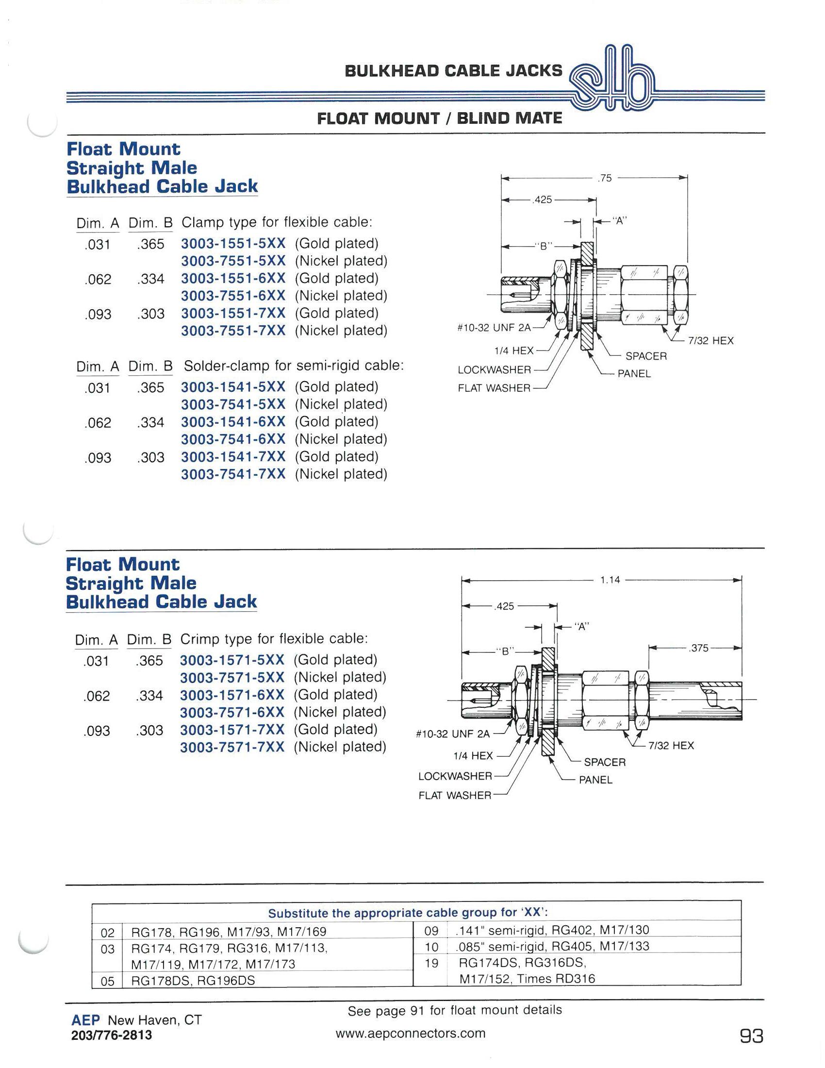
Bulkhead Cable Jacks - Float Mount/Blind Mate
Float Mount
Straight Male
Bulkhead Cable Jack
Dim. A Dim. B Clamp type for flexible cable:
0.031 0.365 3003-1551-5XX (Gold-plated)
3003-7551-5XX (Nickel-plated)
0.062 0.334 3003-1551-6XX (Gold-plated)
3003-7551-6XX (Nickel-plated)
0.093 0.303 3003-1551-7XX (Gold-plated)
3003-7551-7XX (Nickel-plated)
Dim. A Dim. B Solder-clamp for semi-rigid cable:
0.031 0.365 3003-1541-5XX (Gold-plated)
3003-7541-5XX (Nickel-plated)
0.062 0.334 3003-1541-6XX (Gold-plated)
3003-7541-6XX (Nickel-plated)
0.093 0.303 3003-1541-7XX (Gold-plated)
3003-7541-7XX (Nickel-plated)
Float Mount
Straight Male
Bulkhead Cable Jack
Dim. A Dim. B Crimp type for flexible cable:
0.031 0.365 3003-1571-5XX (Gold-plated)
3003-7571-5XX (Nickel-plated)
0.062 0.334 3003-1571-6XX (Gold-plated)
3003-7571-6XX (Nickel-plated)
0.093 0.303 3003-1571-7XX (Gold-plated)
3003-7571-7XX (Nickel-plated)
Substitute XX with the Appropriate Cable Group Below
02 RG178, RG196, M17/93, M17/169 09 0.141˝ semi-rigid, RG402, M17/130
03 RG174, RG179, RG316, M17/113, M17/119, M17/172, M17/173
05 RG178DS, RG196DS
10 0.085˝ semi-rigid, RG405, M17/133
19 RG174DS, RG316DS, M17/152, Times RD316
See page 3-34 for float mount details.
3-36 Go online for data sheets and assembly instructions. Visit www.radiall.com/AEP and enter the part number.
Bulkhead Jack Receptacles - Float Mount/Blind Mate

Float Mount
Right Angle Male
Bulkhead Cable Jack
Dim. A Dim. B Clamp type for flexible cable:
0.031 0.360 3006-1551-5XX (Gold-plated)
3006-7551-5XX (Nickel-plated)
0.062 0.329 3006-1551-6XX (Gold-plated)
3006-7551-6XX (Nickel-plated)
0.093 0.298 3006-1551-7XX (Gold-plated)
3006-7551-7XX (Nickel-plated)
Dim. A Dim. B Solder-clamp for semi-rigid cable:
0.031 0.360 3006-1541-5XX (Gold-plated)
3006-7541-5XX (Nickel-plated)
0.062 0.329 3006-1541-6XX (Gold-plated)
3006-7541-6XX (Nickel-plated)
0.093 0.298 3006-1541-7XX (Gold-plated)
3006-7541-7XX (Nickel-plated)
Float Mount
Right Angle Male
Bulkhead Cable Jack
Dim. A Dim. B Crimp type for flexible cable:
0.031 0.360 3106-1521-5XX (Gold-plated)
3106-7521-5XX (Nickel-plated)
0.062 0.329 3106-1521-6XX (Gold-plated)
3106-7521-6XX (Nickel-plated)
0.093 0.298 3106-1521-7XX (Gold-plated)
3106-7521-7XX (Nickel-plated)
Substitute XX with the Appropriate Cable Group Below 02 RG178, RG196, M17/93, M17/169 09 0.141˝ semi-rigid, RG402, M17/130 03 RG174, RG179, RG316, M17/113, M17/119, M17/172, M17/173 10 0.085˝ semi-rigid, RG405, M17/133 05 RG178DS, RG196DS 19 RG174DS, RG316DS, M17/152, Times RD316
See page 3-34 for float mount details.
3-37 SLB Simplification
Go online for data sheets and assembly instructions. Visit www.radiall.com/AEP and enter the part number.
is Our Innovation.

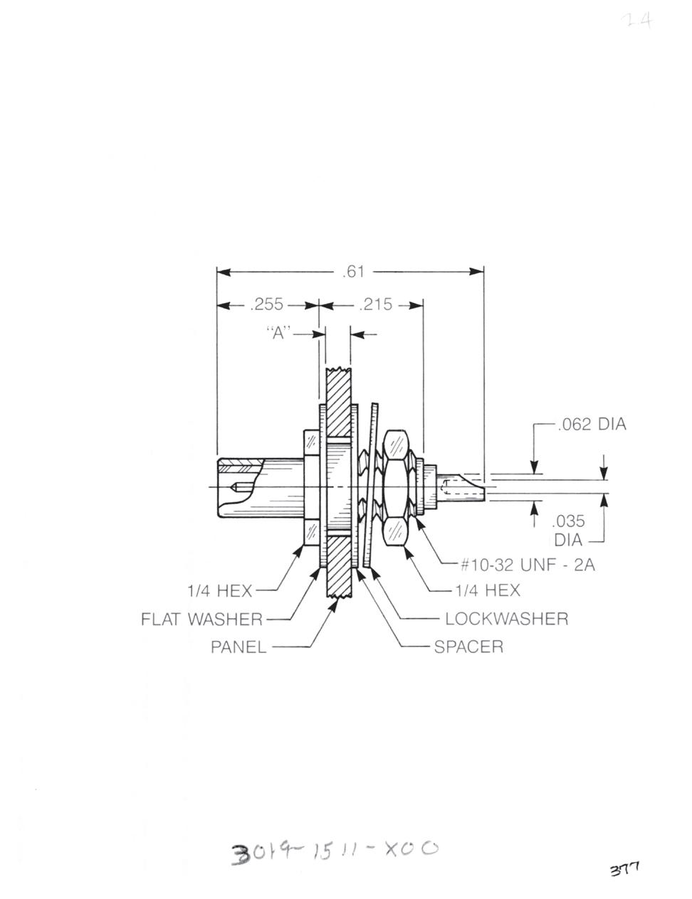
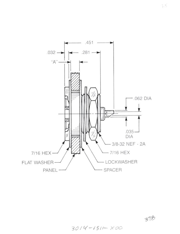
Float Mount Straight Male Bulkhead Jack Receptacle
• Solder pot contact
• Rear mount
Dim. A Dim. B
0.031 0.370
3004-1511-500 (Gold-plated)
3004-7511-500 (Nickel-plated)
0.062 0.339 3004-1511-600 (Gold-plated)
3004-7511-600 (Nickel-plated)
0.093 0.308 3004-1511-700 (Gold-plated)
3004-7511-700 (Nickel-plated)
Float Mount Straight Male Bulkhead Jack Receptacle
• Solder pot contact
• Front mount
Dim. A
0.031
0.062
0.093
3019-1511-500 (Gold-plated)
3019-7511-500 (Nickel-plated)
3019-1511-600 (Gold-plated)
3019-7511-600 (Nickel-plated)
3019-1511-700 (Gold-plated)
3019-7511-700 (Nickel-plated)
Float Mount Straight Male Bulkhead Jack Receptacle
• Solder pot contact
• Recessed front mount
Dim. A
0.031
3014-1511-500 (Gold-plated)
3014-7511-500 (Nickel-plated)
0.062 3014-1511-600 (Gold-plated)
3014-7511-600 (Nickel-plated)
0.093
3014-1511-700 (Gold-plated)
3014-7511-700 (Nickel-plated)
See page 3-34 for float mount details.
3-38 Go online for data sheets and assembly instructions. Visit www.radiall.com/AEP and enter the part number.
Bulkhead Cable Jacks - Float Mount/Blind Mate
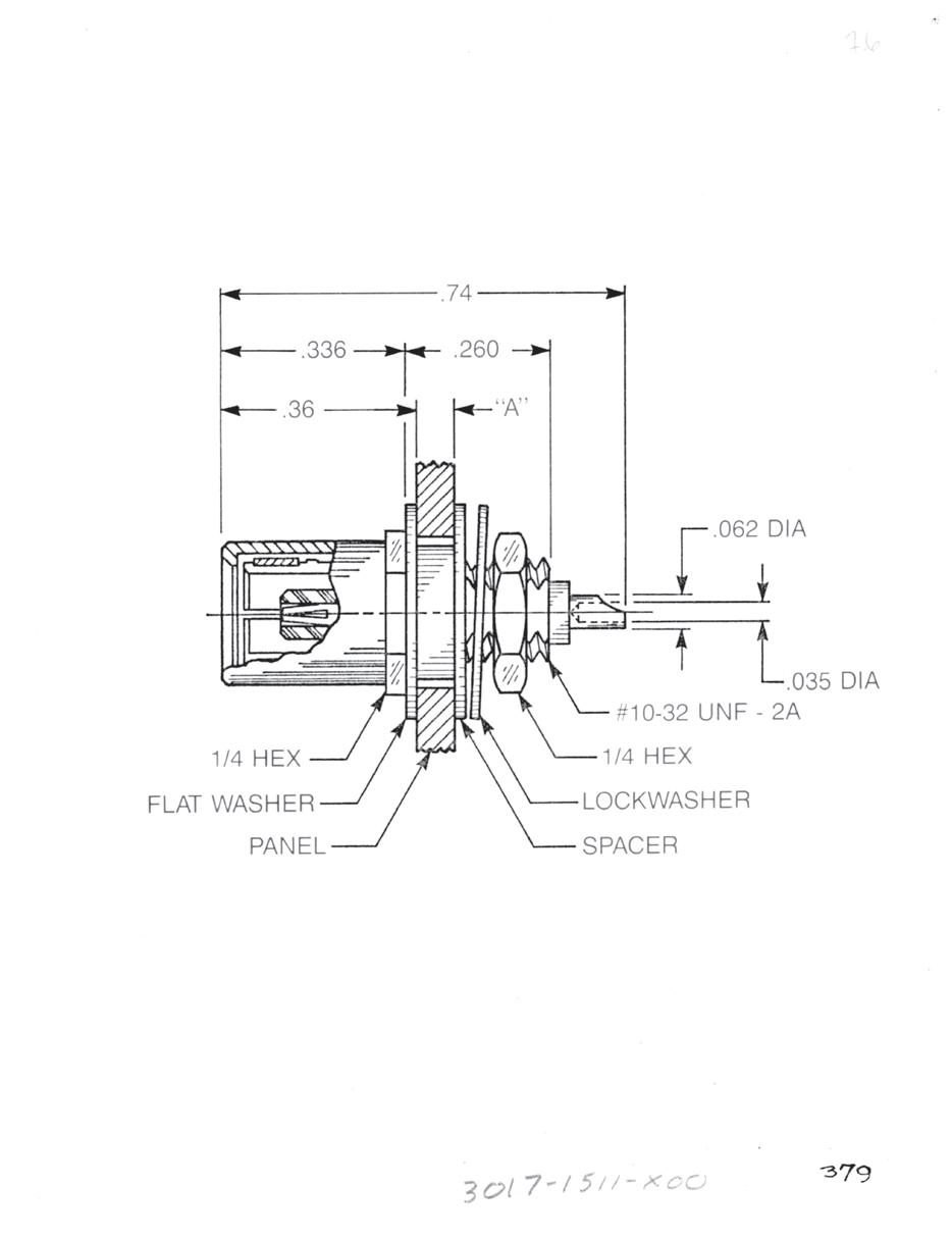
Bulkhead Plug Receptacles - Float Mount/Blind Mate
Float Mount Straight Female Bulkhead Plug Receptacle
• Solder pot contact
• Front mount

• Closed-entry mating end hood
Dim. A
0.031
0.062
0.093
3017-1511-500 (Gold-plated)
3017-7511-500 (Nickel-plated)
3017-1511-600 (Gold-plated)
3017-7511-600 (Nickel-plated)
3017-1511-700 (Gold-plated)
3017-7511-700 (Nickel-plated)
Float Mount Straight Female Bulkhead Plug Receptacle
• Solder pot contact
• Front mount
• Closed-entry mating end hood
Dim. A Dim. B
0.031 0.515 3048-1511-500 (Gold-plated)
3048-7511-500 (Nickel-plated)
0.062 0.484 3048-1511-600 (Gold-plated)
3048-7511-600 (Nickel-plated)
0.093 0.453 3048-1511-700 (Gold-plated)
3048-7511-700 (Nickel-plated)
Float Mount Straight Male Adapter
• Jack to jack
• Connects two plugs
Dim. A Dim. B
0.031 0.360 5252-1501-500 (Gold-plated)
5252-7501-500 (Nickel-plated)
0.062 0.329 5252-1501-600 (Gold-plated)
5252-7501-600 (Nickel-plated)
0.093 0.298 5252-1501-700 (Gold-plated)
5252-7501-700 (Nickel-plated)
See page 3-34 for float mount details.
3-39 SLB Simplification
Go online for data sheets and assembly instructions. Visit www.radiall.com/AEP and enter the part number.
is Our Innovation.

Receptacles - Float Mount/Blind Mate
Float Mount
Straight Male Jack
PCB Receptacle
Dim. A Dim. B
0.031 0.380 3109-1511-500 (Gold-plated)
3109-7511-500 (Nickel-plated)
0.062 0.349 3109-1511-600 (Gold-plated)
3109-7511-600 (Nickel-plated)
0.093 0.318 3109-1511-700 (Gold-plated)
3109-7511-700 (Nickel-plated)
Float Mount
Right Angle Male Jack
PCB Receptacle
Dim. A Dim. B
0.031 0.365 3110-1511-500 (Gold-plated)
3110 -7511-500 (Nickel-plated)
0.062 0.334 3110 -1511-600 (Gold-plated)
3110 -7511-600 (Nickel-plated)
0.093 0.303 3110 -1511-700 (Gold-plated) 3110 -7511-700 (Nickel-plated)
Straight Female Plug
PCB Receptacle
• Closed-entry mating end hood
3025-1511-005 (Gold-plated)
3025-7511-005 (Nickel-plated)
Right Angle Female Plug
PCB Receptacle
• Closed-entry mating end hood
3042-1511-006 (Gold-plated)
3042-7511-006 (Nickel-plated)
See page 3-34 for float mount details.
3-40 Go online for data sheets and assembly instructions. Visit www.radiall.com/AEP and enter the part number.
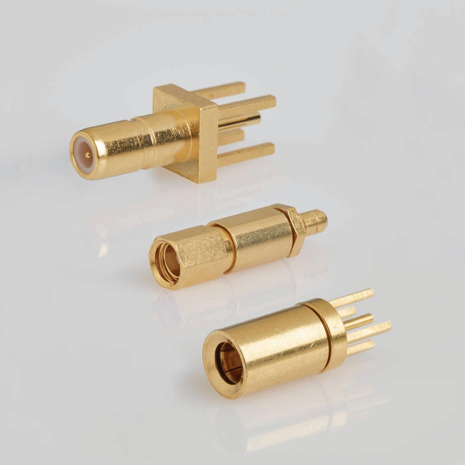
SIMPLIFICATION IS OUR INNOVATON Visit www.radiall.com for more information. SECTION 4 SSMB/SSMC/SSLB
4-1 Simplification is Our Innovation. Go online for data sheets and assembly instructions. Visit www.radiall.com/AEP and enter the part number. SSMB SERIES Specifications 4-3 Cable Plugs 4-4 Cable Jacks 4-5 Bulkhead Receptacles 4-6 P.C. Board Receptacles 4-7 Panel (Flange Mount) Receptacles 4-8 SSMC SERIES Specifications 4-9 Cable Plugs 4-10 Cable Jacks 4-11 Bulkhead Receptacles 4-12 P.C. Board Receptacles 4-13 Receptacles and Adapters 110 SSLB SERIES Mating Plugs 4-15 Cable Plugs 4-16 SECTION 4 TABLE OF CONTENTS
With AEP SSMB and SSMC series microminiature connectors, having to trade reliability for small size is no longer a design consideration. These rugged little connectors have been tested to 1,000 mating cycles with no change in insertion loss or mating forces. They have also passed all MIL-PRF-39012 qualification parameters for SMB connectors.
The key to this reliability is our use of beryllium copper outer contacts in plug connectors and closed entry female contacts.
The standard mating design for SSMB and SSMC series connectors are similar to SMB and SMC but with a size reduction of approximately one-third. This makes them ideal for use in confined areas where the use of wrenches is not practical. Pages 4-15 and 4-16 show a group of plugs with slide-on mating for use where multiple connector pairs must be mated simultaneously.
These connectors have gained wide acceptance and usage in military radio systems, where small size is needed for miniaturization but ruggedness and reliability are paramount.
Because of the SSMB and SSMC series small size and tight tolerance, finishes other than gold-plating are not recommended.
Factory-built cable assemblies using these connectors are available from AEP. The index listing for each connector shows the appropriate cable assembly instruction. Assembly instructions start on page 13-14.
4-2 SSMB/SSMC/SSLB Go online for data sheets and assembly instructions. Visit www.radiall.com/AEP and enter the part number.
Interface Dimensions
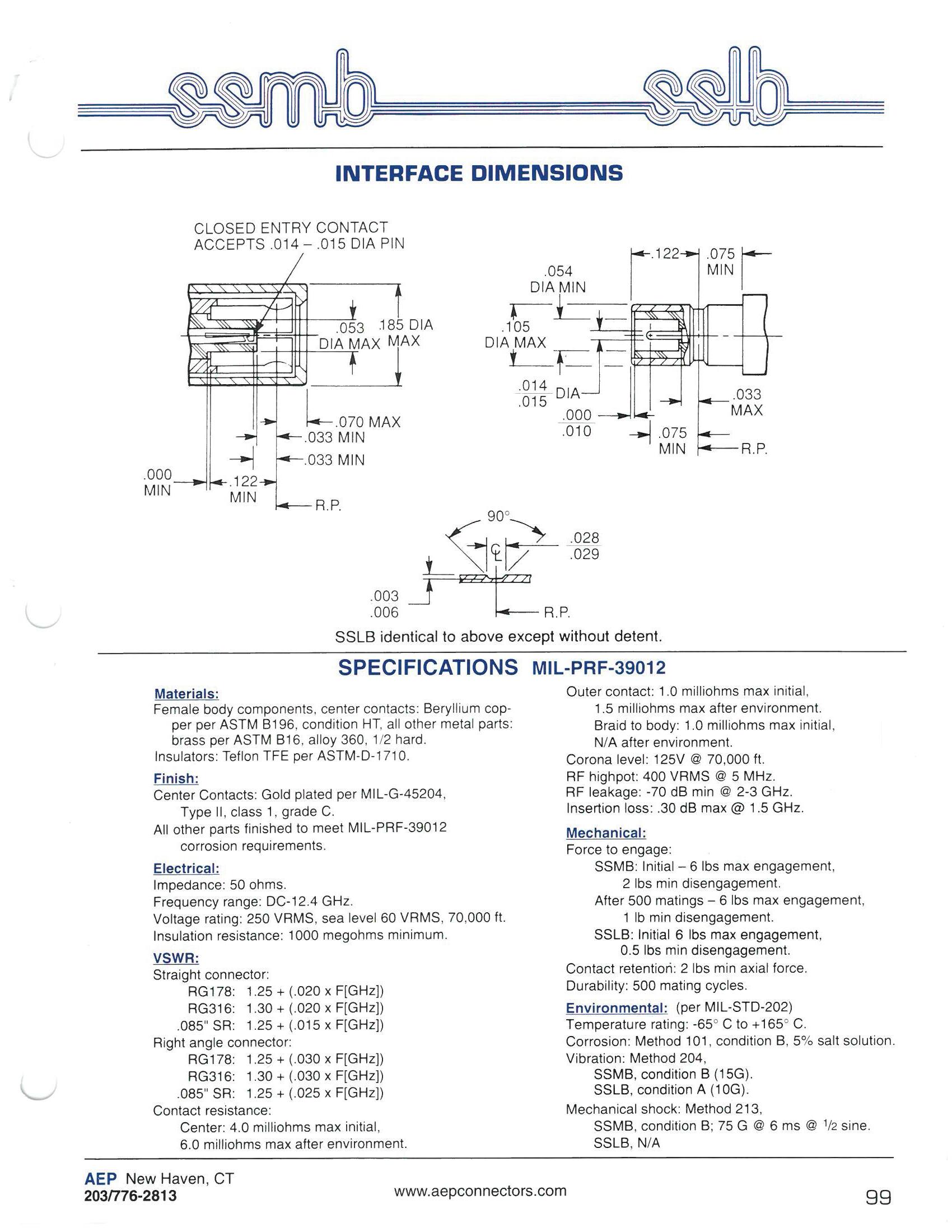
SPECIFICATIONS MIL-PRF-39012
MATERIALS:
Female body components, center contacts: Beryllium cop per per ASTM B196, condition HT
All other metal parts: Brass per ASTM B16. alloy 360, ½ hard
Insulators: Teflon TFE per ASTM-D-1710
FINISH:
Center contacts: Gold-plated per MIL-G-45204, type II, class 1, grade C
All other parts finished to meet MIL-PRF-39012 corrosion requirements.
ELECTRICAL:
Impedance: 50 Ω
Frequency range: DC-12.4 GHz
Voltage rating: 250 VRMS, sea level 60 VRMS, 70,000 ft
Insulation resistance: 1,000 MΩ min
VSWR:
Straight connector:
RG178: 1.25+[0.020×f (GHz)]
RG316: 1.30+[0.020×f (GHz)]
0.085˝ SR: 1.25+[0.015×f (GHz)]
Right angle connector:
RG178: 1.25+[0.030×f (GHz)]
RG316: 1.30+[0.030×f (GHz)]
0.085˝ SR: 1.25+[0.025×f (GHz)]
Contact resistance:
Center: 4.0 mΩ max initial 6.0 mΩ max after environment
Outer contact: 1.0 mΩ max initial 1.5 mΩ max after environment
Braid to body: 1.0 mΩ max initial N/A after environment.
Corona level: 125 V at 70,000 ft
RF highpot: 400 VRMS at 5 MHz
RF leakage: -70 dB min at 2-3 GHz
Insertion loss: 0.30 dB max at 1.5 GHz
MECHANICAL:
Force to engage:
SSMB: Initial -6 lb max engagement, 2 lb min disengagement
After 500 matings -6 lb max engagement, 1 lb min disengagement
SSLB: Initial 6 lb max engagement, 0.5 lb min disengagement
Contact retention: 2 lb min axial force
Durability: 500 mating cycles
ENVIRONMENTAL: (per MIL-STD-202)
Temperature rating: -65° C to +165° C
Corrosion: Method 101, condition B, 5% salt solution
Vibration: Method 204, SSMB, condition B (15G)
SSLB, condition A (10G)
Mechanical shock: Method 213, SSMB, condition B, 75 G at 6 ms at ½ sine SSLB, N/A
4-3 SSMB/SSLB Simplification is Our Innovation. Go online for data sheets and assembly instructions. Visit www.radiall.com/AEP and enter the part number.

Substitute XX with the Appropriate Cable Group Below
02 RG178, RG196, M17/93, M17/169
03 RG174, RG179, RG316, M17/113, M17/119, M17/172, M17/173
05 RG178DS, RG196DS
10 0.085˝ semi-rigid, RG405, M17/133
11 0.047˝ semi-rigid, M17/151
19 RG174DS, RG316DS, M17/152, Times RD316
21 0.056˝ semi-rigid
4-4
Go online for data sheets and assembly instructions. Visit www.radiall.com/AEP and enter the part number.
SSMB

Straight Bulkhead Jack
Crimp type for flexible cable: 7203-1571-0XX
Straight Bulkhead Jack
Solder type for semi-rigid: 7203-1541-0XX
Right Angle Bulkhead Jack
Crimp type for flexible cable: 7406-1521-0XX
Right Angle Bulkhead Jack
Solder type for flexible cable: 7406-1561-0XX
Substitute XX with the Appropriate Cable Group Below
02 RG178, RG196, M17/93, M17/169
03 RG174, RG179, RG316, M17/113, M17/119, M17/172, M17/173
05 RG178DS, RG196DS
10 0.085˝ semi-rigid, RG405, M17/133
11 0.047˝ semi-rigid, M17/151
19 RG174DS, RG316DS, M17/152, Times RD316
21 0.056˝ semi-rigid
4-5 SSMB
Go online for data sheets and assembly instructions. Visit www.radiall.com/AEP and enter the part number.
Simplification is Our Innovation.
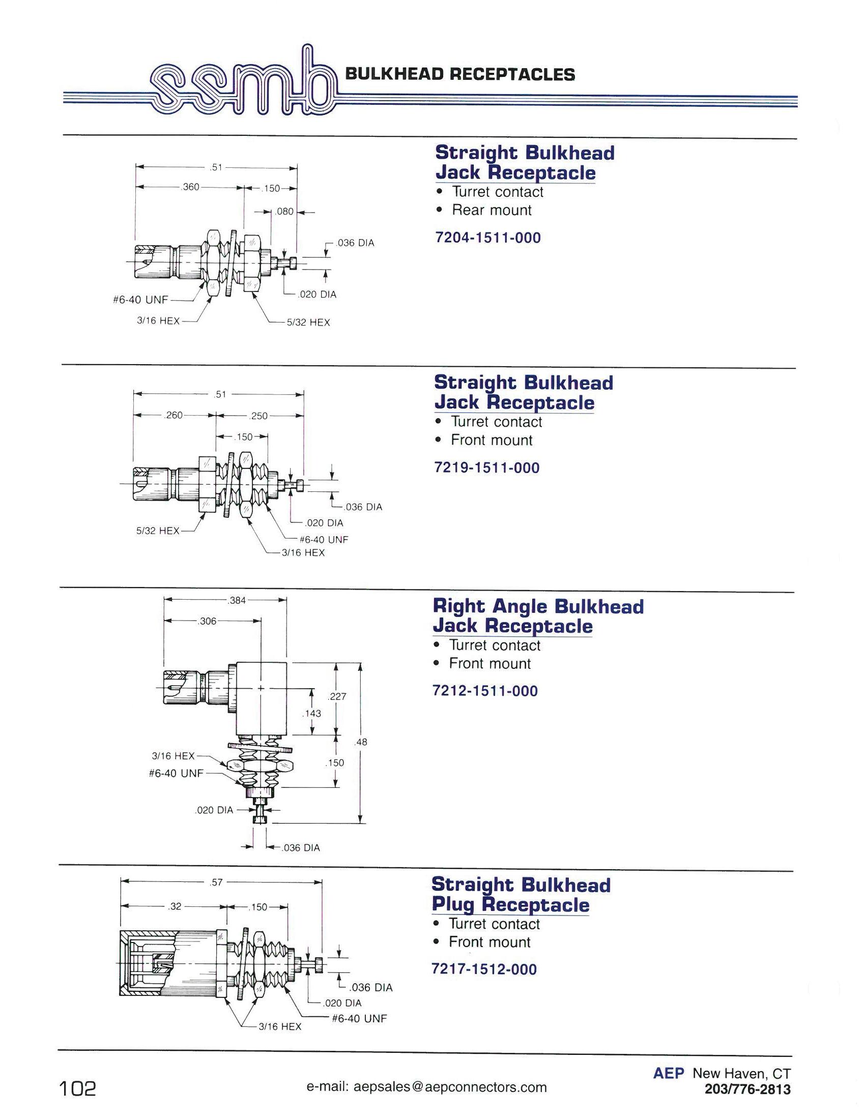
4-6 Go online for data sheets and assembly instructions. Visit www.radiall.com/AEP and enter the part number.

Straight Jack
7209-1511-000
Right Angle Jack
7210-1511-000
Right Angle Bulkhead Jack
7410-1511-000
Straight Plug
7225-1512-000
Right Angle Plug
7242-1511-000
4-7 SSMB Simplification
Go online for data sheets and assembly instructions. Visit www.radiall.com/AEP and enter the part number.
is Our Innovation.

4-8 Go online for data sheets and assembly instructions. Visit www.radiall.com/AEP and enter the part number.
Interface Dimensions
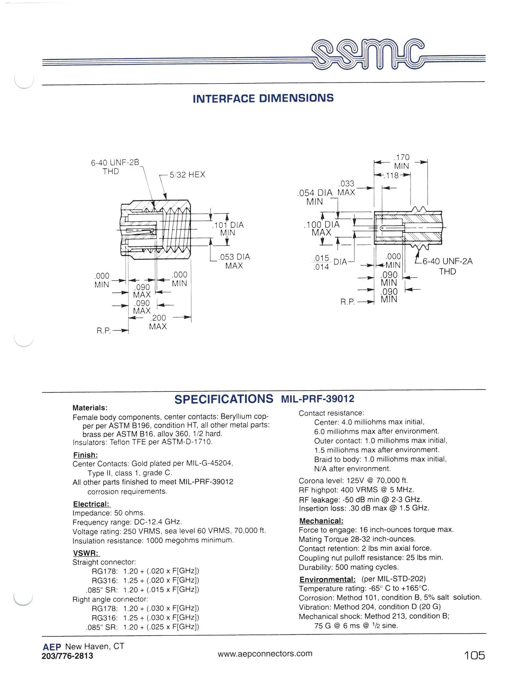
Straight connector:
RG178: 1.20+[0.020×f (GHz)]
RG316: 1.25+[0.020×f (GHz)]
0.085˝ SR: 1.20+[0.015×f (GHz)]
Right angle connector:
RG178: 1.20+[0.030×f (GHz)]
RG316: 1.25+[0.030×f (GHz)]
0.085˝ SR: 1.20+[0.025×f (GHz)]
6.0 mΩ max after environment
1.0 mΩ max initial, 1.5 mΩ max after environment
1.0 mΩ max initial, N/A after environment
0.30 dB max at 1.5 GHz
16 in-oz torque max
2 lb min axial force 25 lb min
ENVIRONMENTAL: (per MIL-STD-202)
Temperature rating: -65° C to +165° C
Corrosion: Method 101, condition B, 5% salt solution
Vibration: Method 204,condition D (20 G)
Mechanical shock: Method 213, condition B; 75 G at 6 ms at ½ sine
4-9 SSMC Simplification is Our Innovation. Go online for data sheets and assembly instructions. Visit www.radiall.com/AEP and enter the part number.
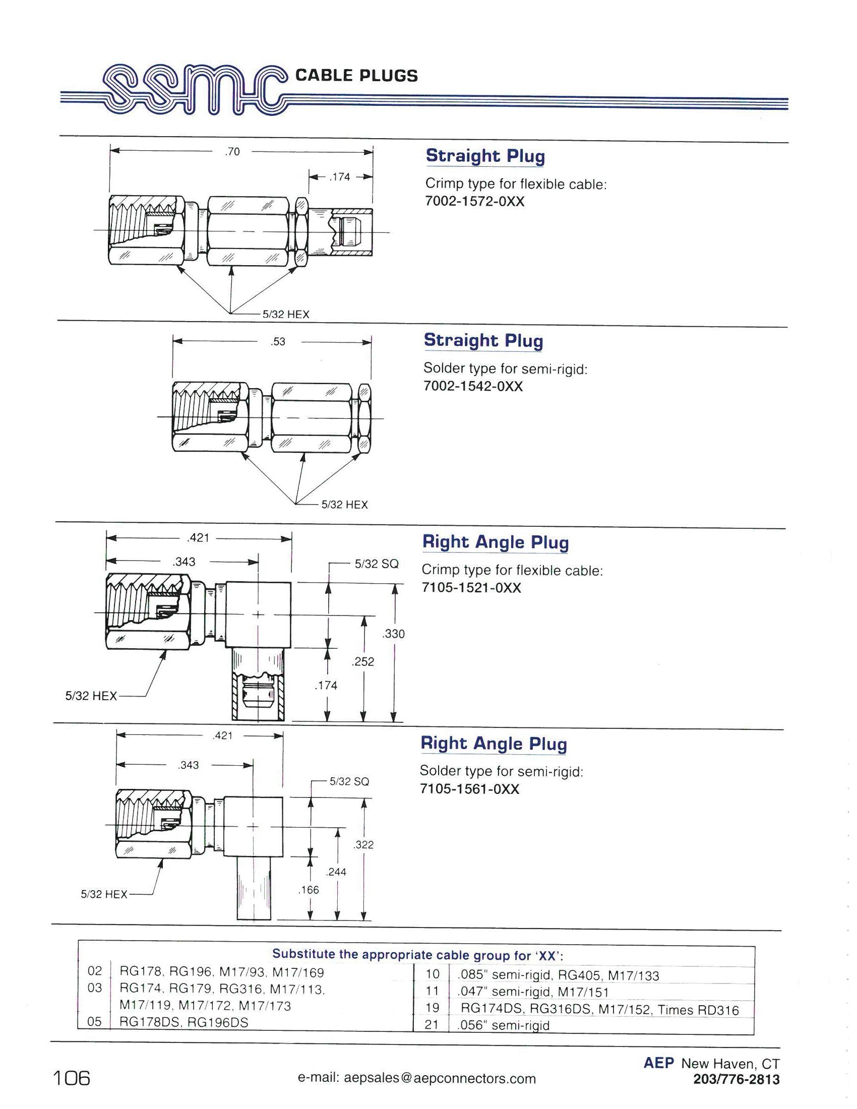
05 RG178DS, RG196DS
0.085˝ semi-rigid, RG405, M17/133
RG174DS, RG316DS, M17/152, Times RD316
21 0.056˝ semi-rigid
4-10 Go online for data sheets and assembly instructions. Visit www.radiall.com/AEP and enter the part number.

Straight Bulkhead Jack
Crimp type for flexible cable: 7003-1572-0XX
Straight Bulkhead Jack
Solder type for semi-rigid: 7003-1542-0XX
Right Angle Bulkhead Jack
Crimp type for flexible cable: 7106-1521-0XX
Right Angle Bulkhead Jack
Solder type for flexible cable: 7106-1561-0XX
Substitute XX with the Appropriate Cable Group Below
10 0.085˝ semi-rigid, RG405, M17/133
11 0.047˝ semi-rigid, M17/151
19 RG174DS, RG316DS, M17/152, Times RD316
05 RG178DS, RG196DS
21 0.056˝ semi-rigid
4-11 SSMC
Go online for data sheets and assembly instructions. Visit www.radiall.com/AEP and enter the part number.
Simplification is Our Innovation.
SSMC
Bulkhead Receptacles
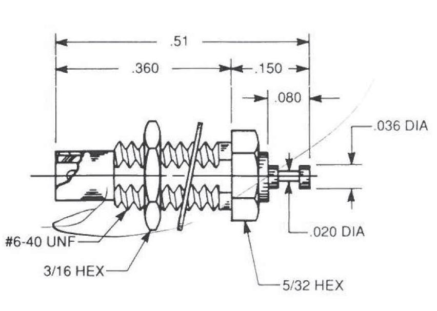
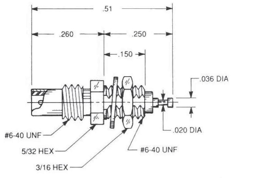
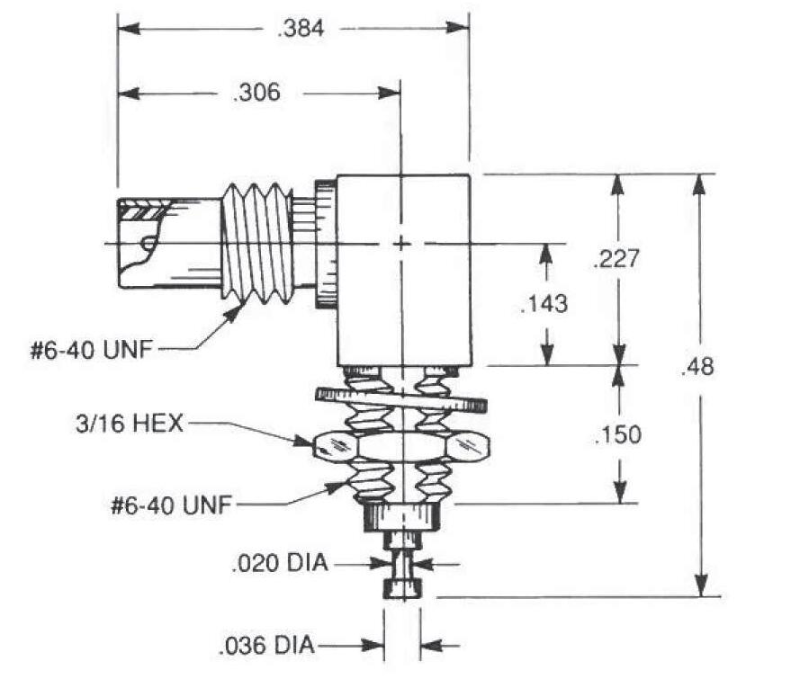
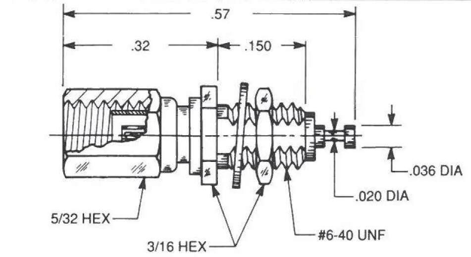
Straight Bulkhead Jack Receptacle
• Turret contact
• Rear mount
7004-1512-000
Straight Bulkhead Jack Receptacle
• Turret contact
• Front mount
7119-1512-000
Right Angle Bulkhead Jack Receptacle
• Turret contact
• Front mount
7012-1511-000
Straight Bulkhead Plug Receptacle
• Turret contact
• Front mount
7017-1512-000
4-12
Go online for data sheets and assembly instructions. Visit www.radiall.com/AEP and enter the part number.

Straight Jack
7009-1511-000
Right Angle Jack
7010-1511-000
Right Angle Bulkhead Jack
7110-1511-000
Straight Plug
7025-1512-000
Right Angle Plug
7042-1511-000
4-13 SSMC Simplification
Go online for data sheets and assembly instructions. Visit www.radiall.com/AEP and enter the part number.
is Our Innovation.

4-14 Go online for data sheets and assembly instructions. Visit www.radiall.com/AEP and enter the part number.
Slide-On Mating Plugs

Simplification is Our Innovation.
AEP SSMB series snap-on connectors were designed to provide the highest practical mating and unmating forces in microminiature size, making them the most rugged and reliable microminiature coaxial connectors available. This high mating force can, however, cause damage to bulkheads or P.C. boards when the connectors are mated in multiple pairs in rack and panel or blind mate applications.
The slide-on SSLB plugs shown here were designed to reduce mating forces from 6 pounds maximum to 3 pounds maximum per pair, and unmating forces from 2 pound minimum to ½ pound minimum per pair. These forces are high enough to ensure consistent outer conductor grounding, but low enough to allow the
The use of external actuators, such as levers or jackscrews, should be considered in applications requiring the simultaneous mating of multiple connector pairs, especially when one side is P.C. board mounted.
These slide-on plugs will mate with any SSMB series snap-on jack.
Slide-On Bulkhead Plug Receptacle
• Turret contact
• Front mount
7317-1512-000
Slide-On Straight PCB Plug
7325-1512-000
Slide-On Right Angle PCB Plug
7342-1511-000
4-15 SSLB
Visit www.radiall.com/AEP and enter the part number.

0.085˝ semi-rigid, RG405, M17/133
M17/119, M17/172, M17/173 19 RG174DS, RG316DS, M17/152, Times RD316
RG178DS, RG196DS
0.056˝ semi-rigid
4-16 Go online for data sheets and assembly instructions. Visit www.radiall.com/AEP and enter the part number.
03
05
21
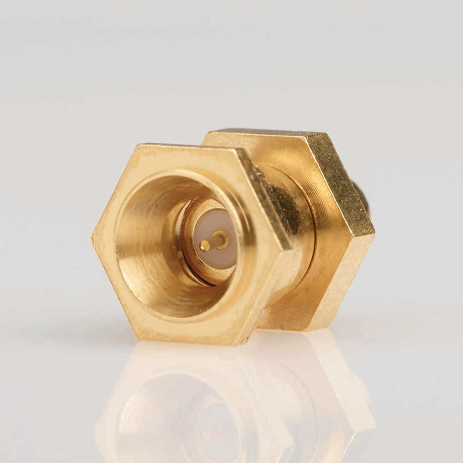
SIMPLIFICATION IS OUR INNOVATON Visit www.radiall.com for more information. SECTION 5 SMP
5-1 Simplification is Our Innovation. Go online for data sheets and assembly instructions. Visit www.radiall.com/AEP and enter the part number. Mating Interfaces 5-2 Male Shrouds with Hermetic Seals and Bullet Adapters 5-3 Male Shrouds with Cable Connectors 5-4 Hermetic Seals 5-5 Straight Female Cable Connectors 7 Straight Male Cable Connectors 7 Male Panel Mounted Cable Connectors (Two-Piece) 8 Hermetic Seal Installation 9 SECTION 5 TABLE OF CONTENTS
SMP Specifications
øD.139.145.139.145.139.145 E.0205.0235.0205.0235N/AN/A F.045.055.045.055.045.055 G.033.037.033.037.033.037 H.051.057.054.060.059.065 J.108.112.108.112.108.112 K28o32o28o32oN/AN/A
Materials:
DimensionFullDetentLimitedDetentSmoothBore Min.Max.Min.Max.Min.Max. øA.014.016.014.016.014.016 øB.114.118.118.122.123.127 øC.124.126.124.126N/AN/A øD.139.145.139.145.139.145 E.0205.0235.0205.0235N/AN/A F.045.055.045.055.045.055 G.033.037.033.037.033.037 H.051.057.054.060.059.065 J.108.112.108.112.108.112 K28o32o28o32oN/AN/A
Specifications
Materials:
Body Components: Beryllium copper per ASTM B196, Condition HT, or stainless steel per ASTM A582, type 303. Contacts: Beryllium copper per ASTM B196, Condition HT.
Insulators: Teflon (PTFE) per ASTM D1710.
Finish:
Center contacts: Gold plated per MIL-G-45204, Type II, Class 1, Grade C.
MATERIALS:
Mechanical:
Force to Engage: Full Detent, 15 pounds.
Limited Detent, 10 pounds.
Smooth Bore, 2 pounds.
Force to Disengage: Full Detent, 5 pounds.
Limited Detent, 2 pounds. Smooth Bore, .5 pounds.
Finish: Center contacts: Gold plated per MIL-G-45204, Type II, Class 1, Grade C.
Other metal parts: Gold plated (beryllium copper or stainless steel) or passivated (stainless steel) to meet current MIL-PRF-39012 corrosion requirements.
Contact Retention: 1.5 pounds min. axial force.
Axial Misalignment: .000 / .010".
parts:
or passivated (stainless
MIL-PRF-39012
Radial Misalignment: .010" centerline to centerline (.020" with special shrouds).
Durability: Full Detent, 100 mating cycles min.
Electrical:
Impedance: 50Ω Frequency range: DC–40 GHz. Voltage Rating: 335V RMS max. @ sea level; 65 V RMS max. @ 70,000 feet.
Dielectric Withstanding Voltage: 500V RMS min. @ sea level;
Limited Detent, 500 mating cycles min.
Smooth Bore, 1,000 mating cycles min.
Body components: Beryllium copper per ASTM B196, condition HT, or stainless steel per ASTM A582, type 303.
125 V RMS min. @ 70,000 feet.
Mechanical:
Force to Engage: Full Detent, 15 pounds.
Limited Detent, 10 pounds. Smooth Bore, 2 pounds.
Force to Disengage: Full Detent, 5 pounds.
Limited Detent, 2 pounds.
Smooth Bore, .5 pounds.
Contact Retention: 1.5 pounds min. axial force.
Axial Misalignment: .000 / .010".
Radial Misalignment: .010" centerline to centerline (.020" with special shrouds).
Durability: Full Detent, 100 mating cycles min.
MECHANICAL:
Limited Detent, 500 mating cycles min.
Smooth Bore, 1,000 mating cycles min.
Environmental (MIL-STD-202):
Environmental (MIL-STD-202): Temperature Range: -65˚ C to +165˚ C.
Vibration: Method 204, condition D.
Force to engage: Full detent, 15 lb
Temperature Range: -65˚ C to +165˚ C.
Vibration: Method 204, condition D.
level; 125 V RMS min. @ 70,000 feet.
Mechanical Shock: Method 213, condition I.
Thermal shock: Method 107, condition B.
Limited detent, 10 lb
Mechanical Shock: Method 213, condition I.
Thermal shock: Method 107, condition B.
VSWR: DC–23 GHz: 1.10:1 max; 23–26.5 GHz: 1.15:1 max;
Contacts: Beryllium copper per ASTM B196, condition HT
26.5–40 GHz: 1.35:1 max.*
Insertion Loss: .10 F (GHz) (female bullets); .12 F (GHz) (cable connectors).
Insulators: Teflon (PTFE) per ASTM D1710
Insulation Resistance: 5,000 megohms minimum.
FINISH:
Outer contact: 2.0 milliohms maximum.
Corona Level: 190V min. @ 70,000 feet.
RF Highpot: 325V RMS @ 5 MHz.
VSWR: DC–23 GHz: 1.10:1 max; 23–26.5 GHz: 1.15:1 max; 26.5–40 GHz: 1.35:1 max.* Insertion Loss: .10 F (GHz) (female bullets); .12 F (GHz) (cable connectors).
Smooth bore, 2 lb
*VSWR for P/N 5280-1502-000 “bullet” adapter.
Performance of other configurations may vary. Contact factory for additional information.
Insulation Resistance: 5,000 megohms minimum.
Contact Resistance: Center contact: 6.0 milliohms maximum.
*VSWR for P/N 5280-1502-000 “bullet” adapter.
Force to disengage: Full detent, 5 lb
Contact Resistance: Center contact: 6.0 milliohms maximum. Outer contact: 2.0 milliohms maximum.
Corona Level: 190V min. @ 70,000 feet.
RF Highpot: 325V RMS @ 5 MHz.
RF Leakage: -80 dB min. to 3 GHz; -65 dB min. 3 GHz–26.5 GHz.
These specifications change periodically with updates to MIL-PRF-39012 requirements. Contact factory for latest specifications.
Performance of other configurations may vary.
Contact factory for additional information.
Limited detent, 2 lb
These specifications change periodically with updates to MIL-PRF-39012 requirements. Contact factory for latest specifications.
Smooth bore, 0.5 lb
RF Leakage: -80 dB min. to 3 GHz; -65 dB min. 3 GHz–26.5 GHz.
Center contacts: Gold-plated per MIL-G-45204, type II, class 1, grade C
Other metal parts: Gold-plated (beryllium copper or stainless steel) or passivated (stainless steel) to meet current MIL-PRF-39012 corrosion requirements
ELECTRICAL:
Impedance: 50 Ω
Frequency range: DC–40 GHz
Voltage rating: 335 VRMS max at sea level; 65 VRMS max at 70,000 ft
Dielectric withstanding voltage: 500 VRMS min at sea level; 1 25 VRMS min at 70,000 ft
VSWR: DC–23 GHz: 1.10:1 max; 23–26.5 GHz: 1.15:1 max; 26.5–40 GHz: 1.35:1 max.*
Insertion Loss: 0.10√f(GHz) (female bullets); 0.12√f (GHz) (cable connectors)
Insulation resistance: 5,000 MΩ min
Contact resistance: Center contact: 6.0 mΩ max
Outer contact: 2.0 mΩs max
Corona Level: 190 V min at 70,000 ft
RF highpot: 325 VRMS at 5 MHz
RF leakage: -80 dB min to 3 GHz; -65 dB min. 3 GHz–26.5 GHz
Contact retention: 1.5 lb min axial force
Axial misalignment: 0.000/0.010˝
Radial misalignment: 0.010˝ centerline to centerline (0.020˝ with special shrouds)
Durability: Full detent, 100 mating cycles min
Limited detent, 500 mating cycles min
Smooth bore, 1,000 mating cycles min
ENVIRONMENTAL (MIL-STD-202):
Temperature range: -65˚ C to +165˚ C
Vibration: Method 204, condition D
Mechanical shock: Method 213, condition I
Thermal shock: Method 107, condition B
*VSWR for P/N 5280-1502-000 “bullet” adapter.
Performance of other configurations may vary.
Contact factory for additional information.
These specifications change periodically with updates to MIL-PRF-39012 requirements. Contact factory for latest specifications.
5-2
Go online for data sheets and assembly instructions. Visit www.radiall.com/AEP and enter the part number. SMP Specifications
SMP
Dimension Full Detent Limited Detent Smooth Bore Min Max Min Max Min Max øA 0.014 0.016 0.014 0.016 0.014 0.016 øB 0.114 0.118 0.118 0.122 0.123 0.127 øC 0.124 0.126 0.124 0.126 N/A N/A øD 0.139 0.145 0.139 0.145 0.139 0.145 E 0.0205 0.0235 0.0205 0.0235 N/A N/A F 0.045 0.055 0.045 0.055 0.045 0.055 G 0.033 0.037 0.033 0.037 0.033 0.037 H 0.051 0.057 0.054 0.060 0.059 0.065 J 0.108 0.112 0.108 0.112 0.108 0.112 K 28 o 32o 28 o 32o N/A N/A Dimension Cabled Uncabled Min Max Min Max øA - 0.135 - 0.135 B 0.025 0.035 0.018 0.025 C 0.132 - 0.112D 0.070 - 0.070E 0.000 0.008 0.000 0.008 F 0.000 0.010 0.000 0.010
SMP
(203) 776-2813 • FAX (203) 776-8294 • www.aep.us APPLIED ENGINEERING PRODUCTS 3
SMP Male Interface Dimensions
Female Interface Dimensions
SMP Specifications SMP Male Interface Dimensions øC J Reference Plane øD øB .005 (.1) X 45o 35o Ref. Ko Ref. øA G E F H
Min.Max.Min.Max.Min.Max. øA.014.016.014.016.014.016
SMP Female Interface Dimensions øA B E Reference Plane F C D EMI anti-rock ring (Cable connectors only) DimensionCabledUncabled Min.Max.Min.Max. øA—.135—.135 B.025.035.018.025
DimensionFullDetentLimitedDetentSmoothBore
øB.114.118.118.122.123.127 øC.124.126.124.126N/AN/A
C.132—.112— D.070—.070— E.000.008.000.008 F.000.010.000.010
(203) 776-2813 • FAX (203) 776-8294 • www.aep.us APPLIED ENGINEERING PRODUCTS 3
Interface Dimensions øC J Reference Plane øD øB .005 (.1) X 45o 35o Ref. Ko Ref. øA G E F H
SMP Specifications SMP
SMP Male
øA B E Reference
SMP Female Interface Dimensions
Plane F C D EMI / anti-rock ring (Cable connectors only) DimensionCabledUncabled Min.Max.Min.Max. øA—.135—.135 B.025.035.018.025 C.132—.112— D.070—.070— E.000.008.000.008 F.000.010.000.010
copper per ASTM B196,
stainless steel per ASTM A582, type 303.
ASTM
Condition HT.
Body Components: Beryllium
Condition HT, or
Contacts: Beryllium copper per
B196,
Insulators: Teflon (PTFE) per ASTM D1710.
Other metal
Gold plated (beryllium copper or stainless steel)
steel) to meet current
corrosion requirements. Electrical: Impedance: 50Ω Frequency range: DC–40 GHz. Voltage Rating: 335V RMS max. @ sea level; 65 V RMS max. @ 70,000 feet. Dielectric Withstanding Voltage: 500V RMS min. @ sea
PANEL MOUNTED SHROUDS
Panel Mounted
With Bullet Adapter
Shrouds
SMP Applications
With Bullet Adapter
7509-9013-000 (Limited detent)
SMP Applications
5280-1502-000 (Bullet adapter)
920-157 (Glass
Shrouds With Bullet Adapter
7509-9013-000 (Limited detent)
7515-9013-000 (Smooth bore)
In low-profile, blind-mate applications, flange-mount shrouds are used with “bullet” adapters to provide axial and radial “float” for proper mating.
In low-profile, blind mate applications, flange-mount shrouds are used with “bullet” adapters to provide axial and radial “float” for proper mating.
The bullet adapter mates with the pins of glass-to-metal hermetic seals soldered into the panels. In these applications, one of the shrouds is typically a “limited detent” type, and the other a “smooth bore” type.This pairing keeps mating and unmating forces to a minimum, and retains the bullet adapter in the “limited detent” shroud when the panels are separated.
The bullet adapter mates with the pins of glass-to-metal hermetic seals soldered into the panels.
7515-9013-000 (Smooth bore)
The space between panels when mated can be changed by the use of different-length bullet adapters.
applications, flange-mount shrouds are used with “bullet” adapters to “float” for proper mating. with the pins of glass-to-metal hermetic seals soldered into the panels. of the shrouds is typically a “limited detent” type, and the other a pairing keeps mating and unmating forces to a minimum, and retains the “limited detent” shroud when the panels are separated. panels when mated can be changed by the use of different-length bullet adapters.
In these applications, one of the shrouds is typically a “limited detent” type, and the other a “smooth bore” type. This pairing keeps mating and unmating forces to a minimum, and retains the bullet adapter in the “limited detent” shroud when the panels are separated.
The space between panels when mated can be changed by the use of different-length bullet adapters.
Spacing for Mounted Shrouds
Spacing for Mounted Shrouds .223 (5.7) .223 (5.7)
(5.8)
Spacing for Mounted Shrouds .223 (5.7)
Shrouds may be mounted with centerline spacing as little as .230" for units with .223" wide flanges. Narrower flanges can be provided to allow for spacing as little as .170" (4.3 mm).
See next page for cable connector applications
(203) 776-2813 • FAX (203) 776-8294 • www.aep.us
may be mounted with centerline spacing as little as .230" for units wide flanges. Narrower flanges can be provided to allow for little as .170" (4.3 mm).
Shrouds may be mounted with centerline spacing as little as 0.230˝ for units with 0.223˝ wide flanges. Narrower flanges can be provided to allow for spacing as little as 0.170˝ (4.3 mm).
See next page for cable connector applications
5-3 SMP Simplification is Our Innovation. Go online for data sheets and assembly instructions. Visit www.radiall.com/AEP and enter the part number.
SMP Applications
APPLIED ENGINEERING PRODUCTS 4
.270 (6.9) Nominal
seal)
920-157 (Glass seal)
.223 (5.7) .230 (5.8) FAX (203) 776-8294 • www.aep.us ENGINEERING PRODUCTS 4
.270 (6.9) Nominal 920-157
5280-1502-000 (Bullet adapter)
(Glass seal)
.230
PANEL MOUNTED SHROUDS
SMP Applications
With Cable Connectors
Panel Mounted Shrouds With Cable Connectors
SMP Applications
Mounted Shrouds With Cable Connectors
SMP Applications
Mounted Shrouds With Cable Connectors
7500-1562-010 (Straight female)
7500-1562-010 (Straight female)
7500-1562-010 (Straight female)
7501-1562-010 (Right angle female)
7516-9013-000 (Full detent)
7501-1562-010 (Right angle female)
7516-9013-000 (Full detent)
7501-1562-010 (Right angle female)
A "full-detent" shroud is used in applications with cable connectors to provide secure mating.
A “full-detent” shroud is used in applications with cable connectors to provide secure mating.
Height above panel for typical straight cable connector
7516-9013-000 (Full detent)
"full-detent" shroud is used in applications with cable connectors to provide secure mating.
Height Above Panel for Typical Straight Cable Connector
Height above panel for typical straight cable connector
(6.6)
7500-1562-010 (Straight female)
7516-9013-000 (Full detent)
"full-detent" shroud is used in applications with cable connectors to provide secure mating.
Height above panel for typical straight cable connector
7500-1562-010 (Straight female) .260 (6.6)
7516-9013-000 (Full detent)
7500-1562-010 (Straight female)
Height above panel for typical right angle cable connector
(6.6)
7516-9013-000 (Full detent)
7501-1562-010 (Right angle female)
Height above panel for typical right angle cable connector
7516-9013-000 (Full detent)
7501-1562-010 (Right angle female)
Height Above Panel for Typical Right Angle Cable Connector
(7.0) .220 (5.6)
Height above panel for typical right angle cable connector
7516-9013-000 (Full detent)
7501-1562-010 (Right angle female)
(5.6) 7516-9013-000 (Full detent)
5-4 SMP Go online for data sheets and assembly instructions. Visit www.radiall.com/AEP and enter the part number.
www.aep.us APPLIED ENGINEERING PRODUCTS 5
(203) 776-2813 • FAX (203) 776-8294 •
.260
.275
(7.0) .220 (5.6)
776-2813
FAX
• www.aep.us APPLIED ENGINEERING PRODUCTS 5
•
(203) 776-8294
.275
(203) 776-2813 • FAX (203) 776-8294 • www.aep.us APPLIED ENGINEERING PRODUCTS 5
.260
.275 (7.0) .220
SMP Applications
SMP Shrouds and Adapters
SMP Shrouds and Adapters
SMP Shrouds and Adapters
MALE SHROUDS FOR USE WITH HERMETIC SEALS
Male Shrouds For Use With Hermetic Seals
Shrouds For Use With Hermetic Seals
SMP Shrouds and Adapters
SMP Shrouds and Adapters
Male Shrouds For Use With Hermetic Seals
Male Shrouds For Use With Hermetic Seals
Detent TypeAEP P/N
Detent Type
Full Detent
7516-9013-000
Full detent 7516-9013-000
Limited Detent 7509-9013-000 Smooth Bore 7515-9013-000
Body material: Stainless steel
Limited detent 7509-9013-000
Smooth bore 7515-9013-000
(3.0)
Body material: Stainless steel
Materials:
Detent TypeAEP P/N Full Detent 7516-9013-000 Limited Detent 7509-9013-000
Body material: Stainless steel
OuterRingandPin: Kovar.
HERMETIC SEAL
Hermetic Seal
Hermetic Seal
Hermetic Seal
GlassBead: Corning 7070 or equivalent.
Finish:
TypeAEP P/N Full Detent 7516-9013-000 Limited Detent 7509-9013-000 Smooth Bore 7515-9013-000
Full Detent 7516-9013-000
Limited Detent 7509-9013-000 Smooth Bore 7515-9013-000
OuterRingandPin: Gold plated per MIL-G-45204, type II, Grade C, Class 1, over nickel per MIL-C-26074, Class I, over copper per MIL-C-14550.
Body material: Stainless steel
Hermeticity:
LeakRate: Less than 1 x 10⁻⁸ cc/second.
See page 9 for hermetic seal installation instructions.
Female-to-Female Straight Bullet Adapters For Use With Shrouds
Materials:
MATERIALS:
Outer ring and pin: Kovar
OuterRingandPin: Kovar.
GlassBead: Corning 7070 or equivalent.
Finish:
Materials:
Body material: Stainless steel Body material: Beryllium
Glass bead: Corning 7070 or equivalent
Materials:
FINISH:
OuterRingandPin: Kovar.
OuterRingandPin: Kovar.
OuterRingandPin: Gold plated per MIL-G-45204, type II, Grade C, Class 1, over nickel per MIL-C-26074, Class I, over copper per MIL-C-14550.
GlassBead: Corning 7070 or equivalent.
GlassBead: Corning 7070 or equivalent. Finish:
Hermeticity:
Finish:
Outer ring and pin: Gold-plated per MIL-G-45204, type II, grade C, class 1, over nickel per MIL-C-26074, class I, over copper per MIL-C-14550
LeakRate: Less than 1 x 10⁻⁸ cc/second.
See page 9 for hermetic seal installation instructions.
OuterRingandPin: Gold plated per MIL-G-45204, type II, Grade C, Class 1, over nickel per MIL-C-26074, Class I, over copper per MIL-C-14550.
HERMETICITY:
OuterRingandPin: Gold plated per MIL-G-45204, type II, Grade C, Class 1, over nickel per MIL-C-26074, Class I, over copper per MIL-C-14550.
Hermeticity:
LeakRate: Less than 1 x 10⁻⁸ cc/second. Detent TypeAEP P/N
Leak rate: Less than 1 × 10 -8 cc /second
Hermeticity:
LeakRate: Less than 1 x 10⁻⁸ cc/second.
See page 9 for hermetic seal installation instructions.
Female-to-Female Straight Bullet Adapters For Use With Shrouds
See page 5-8 for hermetic seal installation instructions.
See page 9 for hermetic seal installation instructions.
FEMALE-TO-FEMALE STRAIGHT BULLET ADAPTERS FOR USE WITH SHROUDS
Female-to-Female Straight Bullet Adapters For Use With Shrouds
Female-to-Female Straight Bullet Adapters For Use With Shrouds
Body material: Beryllium copper
Body material: Beryllium copper
Body material: Beryllium copper
Body material: Beryllium copper
(20.4) 5280-1502-001 1.142 (29.0) 5280-1502-002
Body material: Beryllium copper
Body material: Beryllium copper
5-5 SMP Simplification is Our Innovation. Go online for data sheets and assembly instructions. Visit www.radiall.com/AEP and enter the part number.
AEP
P/N
A AEP P/N 0.805
AEP
920-157 AEP P/N
P/N
5280-1502-000
(203) 776-2813 • FAX
APPLIED ENGINEERING PRODUCTS 6
(203) 776-8294 • www.aep.us
A .140 (3.6) typ. .156 (4.0) wrench flats, 3 places .114 (2.9) typ. ø.185 (4.7) max. ø.131 (3.3) typ. ~ .254 (6.5) .114 (2.9) typ. ø.134 (3.4) ø.131 (3.3) typ. AEP P/N 5280-1502-000 A AEP P/N .805(20.4) 5280-1502-001 1.142(29.0) 5280-1502-002 Hermetic Seal .323 (8.2) ref. .200�.010 (5.1�.3) .063 (1.6) .060 (1.5) ø.097 +.003 -.000 2.5 () +.08 -.00 ø.015 �.001 (.38 �.03) AEP P/N 920-157
.120 (3.0) .045 (1.1) .004 (.1) ø.155 (3.9) ø.163 (4.1) .223 (5.7) ø.625 (15.9) ø.481 (12.2) ø.054 (1.4) ø.103 (2.6) typ.
material:
Body
Beryllium copper
Body material:
(203) 776-2813 • FAX (203) 776-8294 • www.aep.us APPLIED ENGINEERING PRODUCTS 6
Beryllium copper
A .140 (3.6) typ. .156 (4.0) wrench flats, 3 places .114 (2.9) typ. ø.185 (4.7) max. ø.131 (3.3) typ. ~ .254 (6.5) .114 (2.9) typ. ø.134 (3.4) ø.131 (3.3) typ. AEP P/N 5280-1502-000 A AEP P/N .805(20.4) 5280-1502-001 1.142(29.0) 5280-1502-002
.323 (8.2) ref. .200�.010 (5.1�.3) .063 (1.6) .060 (1.5) ø.097 +.003 -.000 2.5 () +.08 -.00 ø.015 �.001 (.38 �.03) AEP P/N 920-157
.120 (3.0) .045 (1.1) .004 (.1) ø.155 (3.9) ø.163 (4.1) .223 (5.7) ø.625 (15.9) ø.481 (12.2) ø.054 (1.4) ø.103 (2.6) typ.
Smooth Bore 7515-9013-000
(203) 776-2813 • FAX (203) 776-8294 • www.aep.us APPLIED ENGINEERING PRODUCTS 6
A .140 (3.6) typ. .156 (4.0) wrench flats, 3 places .114 (2.9) typ. ø.185 (4.7) max. ø.131 (3.3) typ. ~ .254 (6.5) .114 (2.9) typ. ø.134 (3.4) ø.131 (3.3) typ. AEP P/N 5280-1502-000 A AEP P/N .805(20.4) 5280-1502-001 1.142(29.0) 5280-1502-002
.323 (8.2) ref. .200�.010 (5.1�.3) .063 (1.6) .060 (1.5) ø.097 +.003 -.000 2.5 () +.08 -.00 ø.015 �.001 (.38 �.03) AEP P/N 920-157
.120
.045 (1.1) .004
ø.155 (3.9) ø.163 (4.1) .223 (5.7) ø.625 (15.9) ø.481 (12.2) ø.054 (1.4) ø.103 (2.6) typ.
Detent
(.1)
copper
(203) 776-2813 • FAX (203) 776-8294 • www.aep.us APPLIED ENGINEERING PRODUCTS 6
Body material: Beryllium copper
A .140 (3.6) typ. .156 (4.0) wrench flats, 3 places .114 (2.9) typ. ø.185 (4.7) max. ø.131 (3.3) typ. ~ .254 (6.5) .114 (2.9) typ. ø.134 (3.4) ø.131 (3.3) typ. AEP P/N 5280-1502-000 A AEP P/N .805(20.4) 5280-1502-001 1.142(29.0) 5280-1502-002
.323 (8.2) ref. .200�.010 (5.1�.3) .063 (1.6) .060 (1.5) ø.097 +.003 -.000 2.5 () +.08 -.00 ø.015 �.001 (.38 �.03) AEP
P/N 920-157
.120 (3.0) .045 (1.1) .004 (.1) ø.155 (3.9) ø.163 (4.1) .223 (5.7) ø.625 (15.9) ø.481 (12.2) ø.054
ø.103
typ.
(1.4)
(2.6)
SMP Cable Connectors
SMP Cable Connectors
SMP Cable Connectors
SMP Cable Connectors
SMP Cable Connectors
Straight Female Cable Connectors (Direct Solder for Semi-Rigid Cable)
Straight Female Cable Connectors (Direct Solder for Semi-Rigid Cable)
Straight Female Cable Connectors (Direct Solder for Semi-Rigid Cable)
STRAIGHT FEMALE CABLE CONNECTORS (DIRECT SOLDER FOR SEMI-RIGID CABLE)
Straight Female Cable Connectors (Direct Solder for Semi-Rigid Cable)
For .086" semi-rigid cable For .047" semi-rigid cable
For 0.086˝ semi-rigid cable
ring
For .086" semi-rigid cable For .047" semi-rigid cable
For .086" semi-rigid cable For .047" semi-rigid cable
For .086" semi-rigid cable For .047" semi-rigid cable
(6.4)
For 0.047˝ semi-rigid cable
(6.4)
(6.4) ø.131 (3.3) ø.089 (2.3)
(6.4) ø.131 (3.3) ø.089 (2.3)
(6.4)
(6.4)
SMP Cable Connectors
(3.3)
(6.4) ø.131 (3.3) ø.089 (2.3)
EMI/anti-rock ring
EMI/anti-rock ring
EMI/anti-rock ring ~
EMI/anti-rock ring
Straight Female Cable Connectors (Direct Solder for Semi-Rigid Cable) For .086"
TYPE AEP P/N
Type AEP P/N
AEP P/N
(1.3) EMI/anti-rock ring ~
(3.3)
(3.3)
(3.3)
(3.3)
EMI/anti-rock ring ~
EMI/anti-rock ring
EMI/anti-rock ring ~
(1.3)
(1.3)
(1.3)
Standard 7500-1562-010
Standard 7500-1562-010
Standard 7500-1562-010
P/N
Standard 7500-1562-010
High Frequency 7500-1262-010
High Frequency 7500-1262-010
High frequency 7500-1262-010
Standard 7500-1562-010 High Frequency 7500-1262-010
Body material: Beryllium copper
Body material: Beryllium copper
Body material: Beryllium copper
Body material: Beryllium copper
Body material: Beryllium copper
AEP P/N 7500-1582-011
P/N 7500-1582-011
AEP P/N
AEP P/N 7500-1582-011
High Frequency 7500-1262-010 AEP P/N 7500-1582-011
7500-1582-011
Body material: Beryllium copper
Body material: Beryllium copper
Body material: Beryllium copper
Body material: Beryllium copper
Body material: Beryllium copper
Right Angle Female Cable Connectors (Direct Solder for Semi-Rigid Cable)
P/N 7500-1582-011
Right Angle Female Cable Connectors (Direct Solder for Semi-Rigid Cable)
Right Angle Female Cable Connectors (Direct Solder for Semi-Rigid Cable)
RIGHT ANGLE FEMALE CABLE CONNECTORS (DIRECT SOLDER FOR SEMI-RIGID CABLE)
Right Angle Female Cable Connectors (Direct Solder for Semi-Rigid Cable)
For .086" semi-rigid cable
Body material: Beryllium copper
For 0.086˝ semi-rigid cable
Body material: Beryllium copper
For .086" semi-rigid cable
(6.7)
(1.4)
Angle Female Cable Connectors (Direct Solder for Semi-Rigid Cable) For .086" semi-rigid cable For .047" semi-rigid cable
EMI/anti-rock ring
For .086" semi-rigid cable For .047" semi-rigid cable ø.131 (3.3)
ring
P/N
For .047" semi-rigid cable
For 0.047˝ semi-rigid cable
(6.1)
For .086" semi-rigid cable For .047" semi-rigid cable ø.131 (3.3) EMI/anti-rock ring
ring ~
ring
ø.131 (3.3) ø.089 (2.3)
AEP P/N
AEP P/N 7501-1562-010
EMI/anti-rock ring ø.050 (1.3) .241 (6.1) .156 (4.0) .193 (4.9)
ø.131 (3.3)
EMI/anti-rock ring ~ ø.050 (1.3)
(1.3)
(5.6)
For .047" semi-rigid cable ø.131 (3.3)
(3.7)
P/N 7501-1562-010
AEP P/N 7501-1562-011
7501-1562-010 AEP P/N
Body material: Beryllium copper
Body material: Beryllium copper
Body material: Beryllium copper
Body material: Beryllium copper
Body material: Beryllium copper
Body material: Beryllium copper
P/N
Body material: Beryllium copper
P/N 7501-1562-011
7501-1562-011
Body material: Beryllium copper
Body material:
Body material: Beryllium copper
Body material: Beryllium copper
Straight Female Cable Connector (Direct Solder for Semi-Rigid Cable)
STRAIGHT FEMALE CABLE CONNECTOR (DIRECT SOLDER FOR SEMI-RIGID CABLE)
Straight Female Cable Connector (Direct Solder for Semi-Rigid Cable)
Straight Female Cable Connector (Direct Solder for Semi-Rigid Cable) For .086" semi-rigid cable—Snap-In panel mounting (float Mount)
Straight Female Cable Connector (Direct Solder for Semi-Rigid Cable) For .086" semi-rigid cable—Snap-In panel mounting (float Mount)
For .086" semi-rigid cable—Snap-In panel mounting (float Mount)
For 0.086˝ semi-rigid cable—Snap-in panel mounting (float mount)
Panel Drilling
Panel Drilling
Panel Drilling
Panel Drilling
(6.8)
(2.3)
7504-2282-010
Body material: Beryllium copper
Body material: Beryllium copper
Body material: Beryllium copper Body material: Beryllium
Straight Female Cable Connector (Direct Solder for Semi-Rigid Cable) For .086" semi-rigid cable—Snap-In panel mounting (float Mount)
P/N 7504-2282-010
Body material: Beryllium copper
Cable assembly instructions are shipped with each connector.
Body material: Beryllium copper
Cable
Cable assembly instructions are shipped with each connector.
Cable assembly instructions are shipped with each connector.
Cable assembly instructions are shipped with each connector.
5-6 SMP Go online for data sheets and assembly instructions. Visit www.radiall.com/AEP and enter the part number.
AEP
P/N
each
assembly instructions are shipped with
connector.
APPLIED ENGINEERING PRODUCTS
ø.089
30˚ ø.272
.001
ø.093
.500
ø.268 (6.8) ø.292 (7.4)
.093 (2.4)
.234
ø.131
ø.283
(2.3)
�
(6.91 �.03)
�.002 (2.36 �.05)
(12.7) .220 (5.6)
panel
(5.9)
(3.3)
+.002 -.001 (7.19+.05 -.03 ) AEP
ø.131
ø.050
.250
.250
ø.131
ø.089 (2.3)
.241
.156
.145
.222
ø.131 (3.3) ø.089 (2.3) .056 (1.4) .265 (6.7) .156 (4.0) .210 (5.3) .142 (3.6) .222 (5.6) EMI/anti-rock
AEP
AEP
7501-1562-011
(4.0) .193 (4.9)
(3.7)
(5.6)
P/N 7501-1562-010
P/N
copper
ø.089
30˚ ø.272
.500
.220
ø.268
ø.292
.093
.234
ø.131
ø.283
) AEP
(2.3)
�.001 (6.91 �.03) ø.093 �.002 (2.36 �.05)
(12.7)
(5.6)
(6.8)
(7.4)
(2.4) panel
(5.9)
(3.3)
+.002 -.001 (7.19+.05 -.03
P/N 7504-2282-010
ø.131
ø.050
.250
.250
TYPE
.241
.145
.222
ø.089
.056
.265 (6.7) .156
.210 (5.3) .142 (3.6) .222 (5.6)
AEP
ø.050
(6.1) .156 (4.0) .193 (4.9)
(3.7)
(5.6) ø.131 (3.3)
(2.3)
(1.4)
(4.0)
EMI/anti-rock
AEP
ø.089
30˚
.500
ø.268
ø.292 (7.4)
.093 (2.4) panel .234 (5.9) ø.131 (3.3) ø.283
-.001 (7.19+.05 -.03 )
P/N
ø.272 �.001 (6.91 �.03) ø.093 �.002 (2.36 �.05)
(12.7) .220 (5.6)
+.002
AEP
7504-2282-010
.250
ø.131
ø.050
.250
TYPE AEP
EMI/anti-rock
ø.050 (1.3) .241 (6.1) .156 (4.0) .193 (4.9) .145 (3.7) .222 (5.6) ø.131 (3.3) ø.089 (2.3) .056 (1.4) .265 (6.7) .156 (4.0) .210 (5.3) .142 (3.6) .222 (5.6) EMI/anti-rock
AEP
AEP P/N
Cable assembly instructions are shipped with each connector.
ring
P/N 7501-1562-010
7501-1562-011
Beryllium copper Body material: Beryllium copper (203) 776-2813 • FAX (203) 776-8294 • www.aep.us APPLIED ENGINEERING PRODUCTS 7
ø.089 (2.3) 30˚ ø.272 �.001 (6.91 �.03) ø.093 �.002 (2.36 �.05) .500 (12.7) .220 (5.6) ø.268 (6.8) ø.292 (7.4) Panel Drilling .093 (2.4) panel .234 (5.9) ø.131 (3.3) ø.283 +.002 -.001 (7.19+.05 -.03 ) AEP P/N 7504-2282-010
For .086" semi-rigid cable—Snap-In panel mounting (float Mount)
semi-rigid
semi-rigid
.250 (6.4) ø.131 (3.3) ø.050 (1.3) EMI/anti-rock
.250 (6.4) ø.131 (3.3) ø.089
cable For .047"
cable
ring
(2.3) EMI/anti-rock
TYPE AEP P/N Standard 7500-1562-010 High Frequency 7500-1262-010 AEP
ø.131 (3.3) EMI/anti-rock ring ø.050 (1.3) .241 (6.1) .156 (4.0) .193 (4.9) .145 (3.7) .222 (5.6) ø.131 (3.3) ø.089 (2.3) .056 (1.4) .265 (6.7) .156 (4.0) .210 (5.3) .142 (3.6) .222 (5.6) EMI/anti-rock
ring AEP
7501-1562-010 AEP
7501-1562-011
APPLIED
ENGINEERING PRODUCTS
ø.089 (2.3) 30˚ ø.272 �.001
ø.093
.002
.05) .500 (12.7) .220 (5.6) ø.268 (6.8) ø.292
.093
ø.131 (3.3) ø.283 +.002 -.001 (7.19+.05 -.03 ) AEP
(6.91 �.03)
�
(2.36 �
(7.4)
(2.4) panel .234 (5.9)
P/N 7504-2282-010
.250
ø.131
ø.050
(6.4)
.250
TYPE AEP
P/N
AEP
.222
.145
.265
.156
.210
.142
.222 (5.6)
.056
(4.0)
(5.3)
(3.6)
is Our Innovation.
SMP
Cable Connectors
SMP Cable Connectors
STRAIGHT MALE CABLE CONNECTOR (DIRECT SOLDER FOR SEMI-RIGID CABLE)
Straight Male Cable Connector (Direct Solder for Semi-Rigid Cable)
Captive Contact, for 0.086˝ semi-rigid/0.040˝ thick panel
SMP Cable Connectors
Captive Contact, for .086"
Straight Male Cable Connector (Direct Solder for Semi-Rigid Cable)
Captive Contact, for .086" semi-rigid / .040" thick panel
SMP Cable Connectors
(9.9) .158 (4.0)
Detent Type AEP P/N
Detent TypeAEP P/N
Full detent
Straight Male Cable Connector (Direct Solder for Semi-Rigid Cable)
Limited detent
Captive Contact, for .086" semi-rigid / .040" thick panel
Smooth bore
Body material: Beryllium copper
Body material: Beryllium copper
Panel Drilling
(1.0)
7503-1582-010
7506-1582-010
7502-1582-010
Body material: Beryllium copper
Detent TypeAEP P/N
Straight Male Cable Connector (Direct Solder for Semi-Rigid Cable) Captive Contact,
(5.8) ø.089 (2.3)
STRAIGHT MALE CABLE CONNECTOR (DIRECT SOLDER FOR SEMI-RIGID CABLE)
Body material: Beryllium copper
Captive Contact, for 0.086˝ semi-rigid/0.150˝ thick panel
Straight Male Cable Connector (Direct Solder for Semi-Rigid Cable)
(1.0) panel
Detent TypeAEP P/N Full Detent
7503-1582-110 Limited Detent 7506-1582-110
Straight Male Cable Connector (Direct Solder for Semi-Rigid Cable) Captive Contact,
Detent Type AEP P/N
Full detent
Detent TypeAEP P/N
Full Detent
7503-1582-110
7503-1582-110 Limited Detent
Body material: Beryllium copper
Limited detent
7506-1582-110 Smooth Bore 7502-1582-110
Smooth bore
Body material: Beryllium copper
Detent TypeAEP P/N
Body material: Beryllium copper
Straight Male Cable Connector (Catcher’s Mitt* Direct Solder for Semi-Rigid Cable)
Non-Captive Contact, for .086"
/ .150" thick panel
Bore 7502-1582-110
Body material: Beryllium copper
Straight Male Cable Connector (Catcher’s Mitt* Direct Solder for Semi-Rigid Cable)
Panel Drilling
Non-Captive Contact, for .086" semi-rigid / .150" thick panel
7506-1582-110
7502-1582-110
STRAIGHT MALE CABLE CONNECTOR (CATCHER’S MITT* DIRECT SOLDER FOR SEMI-RIGID CABLE)
(14.3)
Drilling
Detent TypeAEP P/N
Full Detent
7503-1083-010
Non-Captive Contact, for 0.086˝ semi-rigid/0.150˝ thick panel
Limited Detent 7506-1083-010
Straight Male Cable Connector (Catcher’s Mitt* Direct Solder for Semi-Rigid Cable)
Smooth Bore 7502-1083-010
Non-Captive Contact, for .086" semi-rigid / .150" thick panel
ø.230 (5.8)
Panel Drilling
-.00 )
Detent TypeAEP P/N
Full Detent
Limited Detent
7503-1083-010
Body material: Stainless Steel
7506-1083-010
Smooth Bore 7502-1083-010
Detent Type AEP P/N
Body material: Stainless Steel
*The “Catcher's Mitt” configuration features a wider-than-standard flare at the mating end, increasing its ability to “capture” a misaligned mating connector and guide it to center for proper mating.
Full detent
Detent TypeAEP P/N Full Detent
Limited Detent
7503-1083-010
Limited detent
7506-1083-010
7503-1083-010
7506-1083-010
*The “Catcher's Mitt” configuration features a wider-than-standard flare at the mating end, increasing its ability to “capture” a misaligned mating connector and guide it to center for proper mating.
These panel connectors have two-piece bodies; after the rear assembly is inserted through the panel, the front shroud is assembled and tightened with a screwdriver or wrench.
Smooth Bore 7502-1083-010
Smooth bore
Body material: Stainless Steel
7502-1083-010
These panel connectors have two-piece bodies; after the rear assembly is inserted through the panel, the front shroud is assembled and tightened with a screwdriver or wrench.
Body material: Stainless steel
*The “Catcher's Mitt” configuration features a wider-than-standard flare at the mating end, increasing its ability to “capture” a misaligned mating connector and guide it to center for proper mating.
(203) 776-2813 • FAX (203) 776-8294 • www.aep.us
Cable assembly instructions are shipped with each connector. (203) 776-2813 • FAX (203) 776-8294 • www.aep.us
*The “Catcher's Mitt” configuration features a wider-than-standard flare at the mating end, increasing its ability to “capture” a misaligned mating connector and guide it to center for proper mating.
These panel connectors have two-piece bodies; after the rear assembly is inserted through the panel, the front shroud is assembled and tightened with a screwdriver or wrench.
These panel connectors have two-piece bodies; after the rear assembly is inserted through the panel, the front shroud is assembled and tightened with a screwdriver or wrench.
Cable assembly instructions are shipped with each connector.
Cable assembly instructions are shipped with each connector.
Cable assembly instructions are shipped with each connector. (203) 776-2813 • FAX (203)
5-7 SMP Simplification
Go online for data sheets and assembly instructions. Visit www.radiall.com/AEP and enter the part number.
APPLIED ENGINEERING PRODUCTS
8
semi-rigid
thick
.388 (9.9) .158 (4.0) .040 (1.0) panel Slot .043 (1.1) wide .250 (6.4) hex Panel Drilling ø.230 (5.8) ø.089 (2.3) ø.184 (4.7) ø.187 �.001 (4.75 �.03) .040 �.001 (1.02 �.03) .040 (1.0)
/ .040"
panel
Full Detent
Limited Detent 7506-1582-010 Smooth Bore 7502-1582-010
7503-1582-010
for .086" semi-rigid
.150" thick panel .390 (9.9) .190 (4.8) .150 (3.8) panel ø.199 (5.1) ø.195 (5.0) ø.089 (2.3) .250 (6.4) hex .250 (6.4) hex .150 �.001 (3.81 �.03) Panel Drilling ø.200 +.001 -.000 (5.08+.03 -.00 )
/
Smooth
Bore 7502-1582-110
semi-rigid
.562 (14.3) .187 (4.7) ø.199 (5.1) Slot .043 (1.1) wide .150 (3.8) panel .048 (1.2) ø.089 (2.3) .188 (4.8) wrench flat .150 �.001 (3.81 �.03)
ø.200 +.001 -.000 (5.08+.03 -.00 ) ø.230 (5.8)
APPLIED
PRODUCTS 8
ENGINEERING
.388
.040
panel Slot .043 (1.1) wide .250 (6.4) hex Panel Drilling ø.230 (5.8) ø.089 (2.3) ø.184 (4.7) ø.187 �.001 (4.75 �.03) .040 �.001 (1.02 �.03) .040 (1.0) Detent TypeAEP
Full Detent 7503-1582-010 Limited Detent 7506-1582-010 Smooth Bore 7502-1582-010
P/N
Captive Contact, for .086" semi-rigid / .150" thick panel .390 (9.9) .190 (4.8) .150 (3.8) panel ø.199 (5.1) ø.195 (5.0) ø.089 (2.3) .250 (6.4) hex .250 (6.4) hex .150 �.001 (3.81 �.03) Panel
ø.200 +.001 -.000
Drilling
(5.08+.03 -.00 )
.562
.187
Slot .043
wide .150 (3.8) panel .048 (1.2) ø.089
.188 (4.8) wrench flat .150 �.001 (3.81 �.03)
(5.08+.03
(4.7) ø.199 (5.1)
(1.1)
(2.3)
Panel
ø.200 +.001 -.000
776-8294
APPLIED ENGINEERING PRODUCTS 8
• www.aep.us
.388
.040
Slot .043 (1.1) wide .250
(9.9) .158 (4.0)
(6.4) hex
ø.230
ø.184 (4.7) ø.187 �.001 (4.75 �.03) .040 �.001 (1.02 �.03) .040 (1.0)
Full
Smooth
Detent 7503-1582-010 Limited Detent 7506-1582-010
Bore 7502-1582-010
for
semi-rigid
.390 (9.9) .190 (4.8) .150 (3.8) panel ø.199 (5.1) ø.195 (5.0) ø.089 (2.3) .250 (6.4) hex .250 (6.4) hex ~ .150 �.001 (3.81 �.03) Panel Drilling ø.200 +.001 -.000 (5.08+.03 -.00 )
.086"
/ .150" thick panel
Full
Limited
Smooth
Detent 7503-1582-110
Detent 7506-1582-110
.562
(4.7) ø.199 (5.1) Slot .043 (1.1) wide .150 (3.8) panel .048 (1.2) ø.089 (2.3) .188 (4.8) wrench flat .150 �.001 (3.81 �.03)
ø.200 +.001 -.000 (5.08+.03 -.00 ) ø.230 (5.8)
(14.3) .187
SMP Hermetic Seal Installation
SMP Hermetic Seal Installation
HERMETIC SEAL FIXTURING TOOL
Hermetic Seal Fixturing Tool
SMP Hermetic Seal Installation
SMP Hermetic Seal Installation
SMP
Hermetic Seal Fixturing Tool .730 (18.5)
Hermetic Seal Fixturing Tool
Hermetic Seal Installation
(18.5)
Hermetic Seal Fixturing Tool
(15.9) ø.481
SMP Hermetic Seal Installation
Hermetic Seal Fixturing Tool
(Drawing ≈
Hermetic Seal Installation
HERMETIC SEAL INSTALLATION
Hermetic Seal Installation
Hermetic Seal Installation
1
Hermetic Seal Installation
Body material: Tool steel
Body material: Tool steel
Body material: Tool steel
Body material: Tool steel
Body material: Tool steel
Drill panel as shown.
ø.035 (.9)
Front of seal should be as close to flush as possible with front surface of panel; if front of seal is below panel surface, an air gap is created which adversely affects electrical performance.
Drill panel as shown.
Drill panel as shown.
• Drill panel as shown.
Front of seal should be flush with front surface of panel, but may protrude up to .005" without affecting performance.
ø.035 (.9) .060 (.15) Panel Hermetic seal Counterbore
Front of seal should be as close to flush as possible with front surface of panel; if front of seal is below panel surface, an air gap is created which adversely affects electrical performance.
Drill panel as shown.
Front of seal should be as close to flush as possible with front surface of panel; if front of seal is below panel surface, an air gap is created which adversely affects electrical performance.
tool to panel with screws
Spring-loaded plunger holds seal in place during soldering. Solder fills counterbore when melted.
Drill panel as shown.
• Front of seal should be as close to flush as possible with front surface of panel; if front of seal is below panel surface, an air gap is created which adversely affects electrical performance.
Front of seal should be flush with front surface of panel, but may protrude up to .005" without affecting performance.
Front of seal should be as close to flush as possible with front surface of panel; if front of seal is below panel surface, an air gap is created which adversely affects electrical performance.
Front of seal should be flush with front surface of panel, but may protrude up to .005" without affecting performance.
Place preformed solder ring into counterbore of tool. 2
Secure tool to panel with screws. Apply heat to completely melt solder. Remove tool only after solder joint has cooled.
Fasten tool to panel with screws
Spring-loaded plunger holds seal in place during soldering. Solder fills counterbore when melted.
• Front of seal should be flush with front surface of panel, but may protrude up to 0.005� without affecting performance.
Front of seal should be as close to flush as possible with front surface of panel; if front of seal is below panel surface, an air gap is created which adversely affects electrical performance.
Front of seal should be flush with front surface of panel, but may protrude up to .005" without affecting performance.
2
Front of seal should be flush with front surface of panel, but may protrude up to .005" without affecting performance.
2
Form solder ring of a size to completely fill panel counterbore when melted.
Place preformed solder ring into counterbore of tool. 2
Form solder ring of a size to completely fill panel counterbore when melted. Place preformed solder ring into counterbore of tool. 2
Form solder ring of a size to completely fill panel counterbore when melted.
Place preformed solder ring into counterbore of tool.
Form solder ring of a size to completely fill panel counterbore when melted.
• Form solder ring of a size to completely fill panel counterbore when melted.
• Place preformed solder ring into counterbore of tool.
Secure tool to panel with screws. Apply heat to completely melt solder. Remove tool only after solder joint has cooled. 3
Spring-loaded plunger holds seal in place during soldering. Solder fills counterbore when melted.
Spring-loaded plunger holds seal in place during soldering. Solder fills counterbore when melted.
Fasten tool to panel with screws
Secure tool to panel with screws. Apply heat to completely melt solder. Remove tool only after solder joint has cooled.
Fasten tool to panel with screws
Secure tool to panel with screws. Apply heat to completely melt solder. Remove tool only after solder joint has cooled. 3
• Secure tool to panel with screws.
• Apply heat to completely melt solder.
Fasten tool to panel with screws
• Remove tool only after solder joint has cooled.
Secure tool to panel with screws. Apply heat to completely melt solder. Remove tool only after solder joint has cooled.
4
Secure SMP shroud flange to panel with screws.
Form solder ring of a size to completely fill panel counterbore when melted. Place preformed solder ring into counterbore of tool.
Secure SMP shroud flange to panel with screws.
Secure SMP shroud flange to panel with screws. 4
Secure SMP shroud flange to panel with screws.
• Secure SMP shroud flange to panel with screws.
Secure SMP shroud flange to panel with screws.
5-8 SMP Go online for data sheets and assembly instructions. Visit www.radiall.com/AEP and enter the part number.
1. 3. 2. 4.
AEP P/N TA-0453
(203) 776-2813 • FAX (203) 776-8294 • www.aep.us APPLIED ENGINEERING PRODUCTS 9
Panel Counterbore Tool TA-0453 Solder ring Plunger .012 +.002 -.001 .3 () +.05 -.03 .060 +.001 -.000 1.5 () +.03 -.00 ø.102 �.001 (2.6 �.03) ø.127 �.001 (3.2 �.03) Seal flush to .005 (.1) above front of panel ø.035 (.9) .060 (.15) Panel Hermetic seal Counterbore SMP shroud 920-157 Hermetic seal Tool
TA-0453
Spring-loaded plunger holds seal in place during soldering. Solder fills counterbore when melted.
Fasten
1
3
4
.730
ø.625
(12.2) ø.103 (2.6) typ. ø.165 (4.2) (Drawing 200% actual size) ø.072 (1.8) plunger ø.140 (3.6) counterbore, .030 (.8) deep AEP
TA-0453
(203) 776-2813 • FAX (203) 776-8294 • www.aep.us APPLIED ENGINEERING PRODUCTS 9
(18.5) .062 (1.6) .165 (4.2)
P/N
Body material: Tool steel
Panel Counterbore Tool TA-0453 Solder ring Plunger .012 +.002 -.001 .3 () +.05 -.03 .060 +.001 -.000 1.5 () +.03 -.00 ø.102 �.001 (2.6 �.03) ø.127 �.001 (3.2 �.03)
above
of panel
Seal flush to .005 (.1)
front
.060
Panel Hermetic
SMP
920-157 Hermetic seal Tool
(.15)
seal Counterbore
shroud
TA-0453
1
3
4
.062 (1.6) .165 (4.2) ø.625 (15.9) ø.481 (12.2) ø.103
typ.
(2.6)
ø.165 (4.2)
200% actual size) ø.072 (1.8) plunger ø.140 (3.6) counterbore, .030 (.8) deep AEP P/N
TA-0453
(203) 776-2813 • FAX (203) 776-8294 • www.aep.us APPLIED ENGINEERING PRODUCTS 9
Panel Counterbore Tool TA-0453 Solder ring Plunger .012 +.002 -.001 .3 () +.05 -.03 .060 +.001 -.000 1.5 () +.03 -.00 ø.102 �.001 (2.6 �.03) ø.127 �.001 (3.2 �.03)
Seal flush to .005 (.1) above front of panel
SMP shroud 920-157 Hermetic seal
Tool TA-0453
1
3
4
.730
.062
.165
ø.625
(12.2) ø.103 (2.6) typ. ø.165 (4.2) (Drawing ≈ 200% actual size) ø.072 (1.8) plunger ø.140 (3.6) counterbore, .030 (.8) deep AEP P/N TA-0453
(18.5)
(1.6)
(4.2)
(15.9) ø.481
(203) 776-2813 • FAX (203) 776-8294 • www.aep.us APPLIED ENGINEERING PRODUCTS 9
Hermetic
Panel Counterbore Tool TA-0453
ring Plunger .012 +.002 -.001 .3 () +.05 -.03 .060 +.001 -.000 1.5 () +.03 -.00 ø.102 �.001 (2.6 �.03) ø.127 �.001 (3.2 �.03) Seal flush to .005 (.1) above front of panel ø.035 (.9) .060 (.15) Panel Hermetic seal Counterbore SMP shroud 920-157 Hermetic seal Tool TA-0453
Seal Installation
Solder
1
.062 (1.6) .165 (4.2) ø.625 (15.9) ø.481 (12.2) ø.103 (2.6) typ. ø.165 (4.2) (Drawing ≈ 200% actual size) ø.072 (1.8) plunger ø.140 (3.6) counterbore, .030 (.8) deep AEP P/N TA-0453
.730
(203) 776-2813 •
(203) 776-8294 • www.aep.us APPLIED ENGINEERING PRODUCTS 9
FAX
Panel Counterbore Tool TA-0453 Solder ring Plunger .012 +.002 -.001 .3 () +.05 -.03 .060 +.001 -.000 1.5 () +.03 -.00 ø.102 �.001 (2.6 �.03) ø.127 �.001 (3.2 �.03) Seal flush to .005 (.1) above front of panel
.060 (.15) Panel Hermetic seal Counterbore SMP shroud 920-157 Hermetic seal Tool TA-0453
ø.035 (.9)
.730 (18.5) .062 (1.6) .165 (4.2) ø.625 (15.9) ø.481 (12.2) ø.103 (2.6) typ. ø.165
(Drawing 200% actual size) ø.072 (1.8) plunger ø.140
.030
deep
TA-0453
(4.2)
(3.6) counterbore,
(.8)
AEP P/N
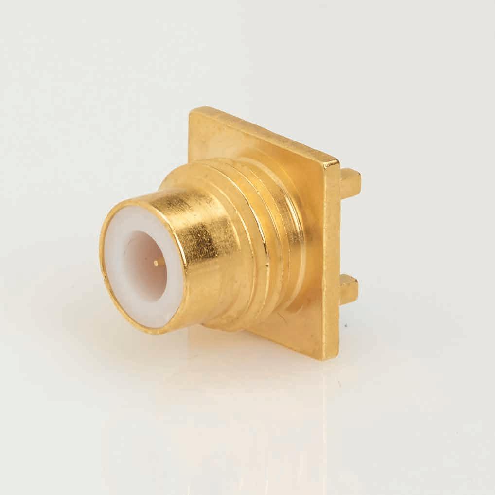
SIMPLIFICATION IS OUR INNOVATON Visit www.radiall.com for more information. SECTION 6 75
OHM
6-1 Simplification is Our Innovation. Go online for data sheets and assembly instructions. Visit www.radiall.com/AEP and enter the part number. SECTION 6 TABLE OF CONTENTS Specifications 6-3 Screw-On Mating: Cable Plugs 6-4 Cable Jacks 6-5 Receptacles 6-6 Adapters and Terminations 6-7 Snap-On Mating: Cable Plugs 6-8 Cable Jacks 6-9 Receptacles 6-10 Adapters and Terminations 6-12
The 75 ohm connectors shown on the following pages provide matched impedance for critical applications such as CATV or Telecom. The screw-on interface is similar in configuration to SMC, and the snap-on interface is similar in configuration to SMB. The cable attachment methods are the same as shown on page 3-5.
Standard cables for use with these connectors are shown at the bottom of the appropriate product pages. A complete listing of cable groups is provided on page 13-6. All the items shown are available with either gold or nickel-plated bodies; part numbers for each finish are shown on the product pages. The index listing shows the appropriate cable assembly instruction. Assembly instructions start on page 13-7.
Factory-built cable assemblies using these connectors are available from AEP.
6-2 75 OHM Go online for data sheets and assembly instructions. Visit www.radiall.com/AEP and enter the part number.
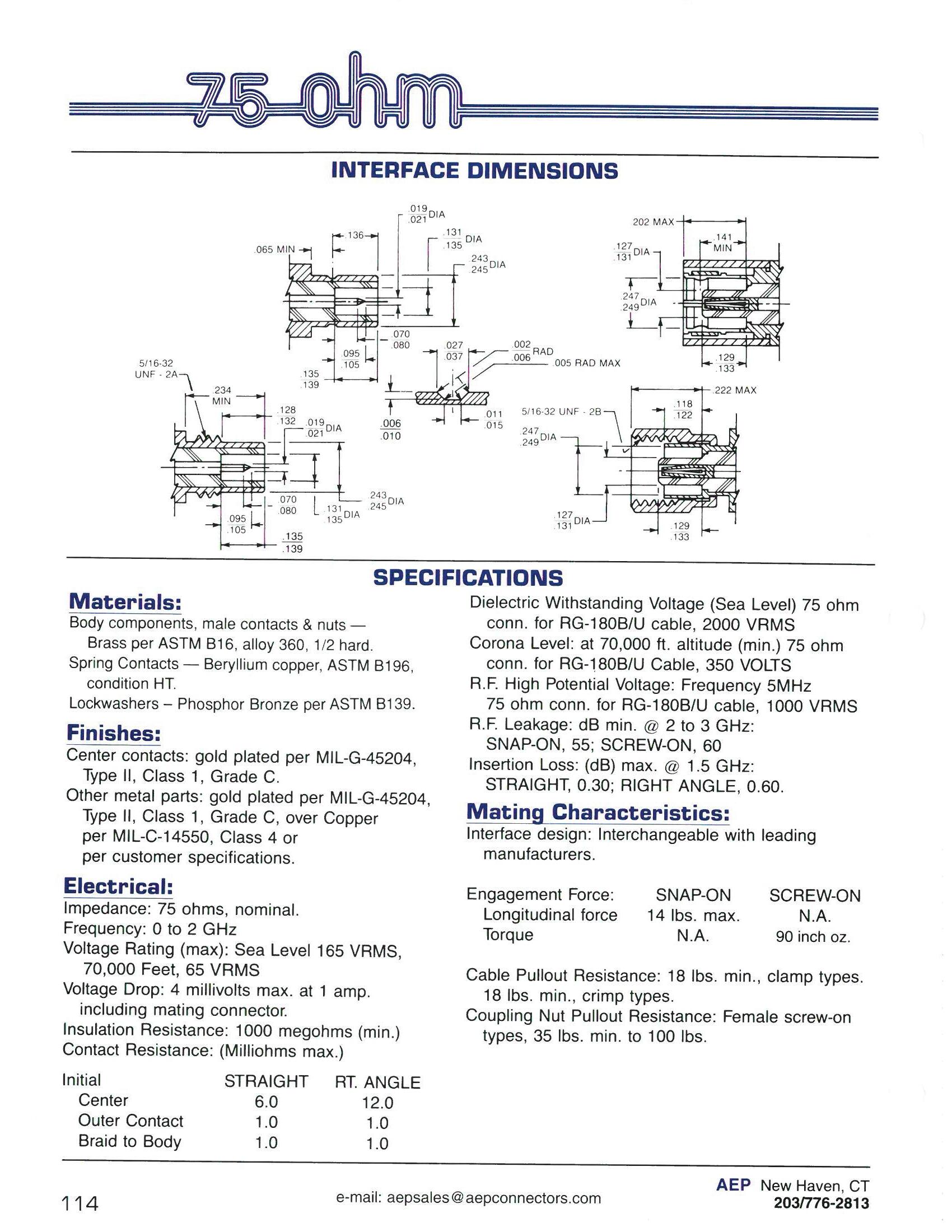
Interchangeable with leading manufacturers
6-3 75 OHM Simplification is Our Innovation. Go online for data sheets and assembly instructions. Visit www.radiall.com/AEP and enter the part number.
1.0 1.0
Braid to body
Plugs - Screw-On Mating
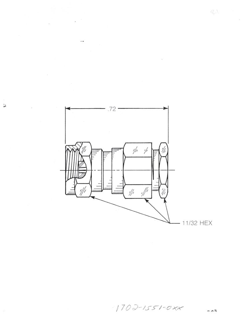
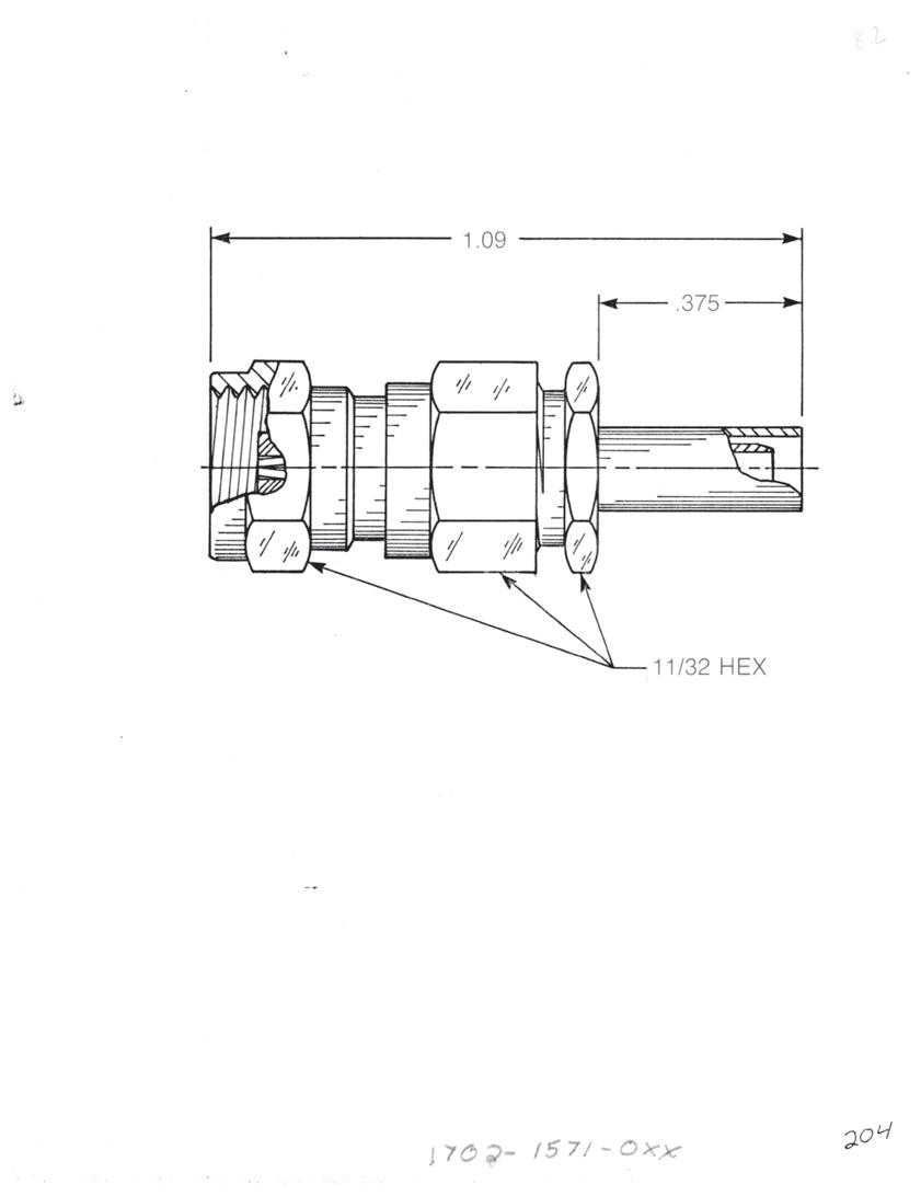
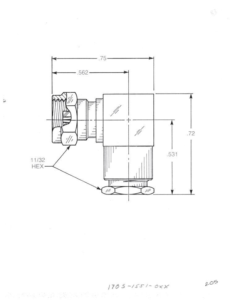
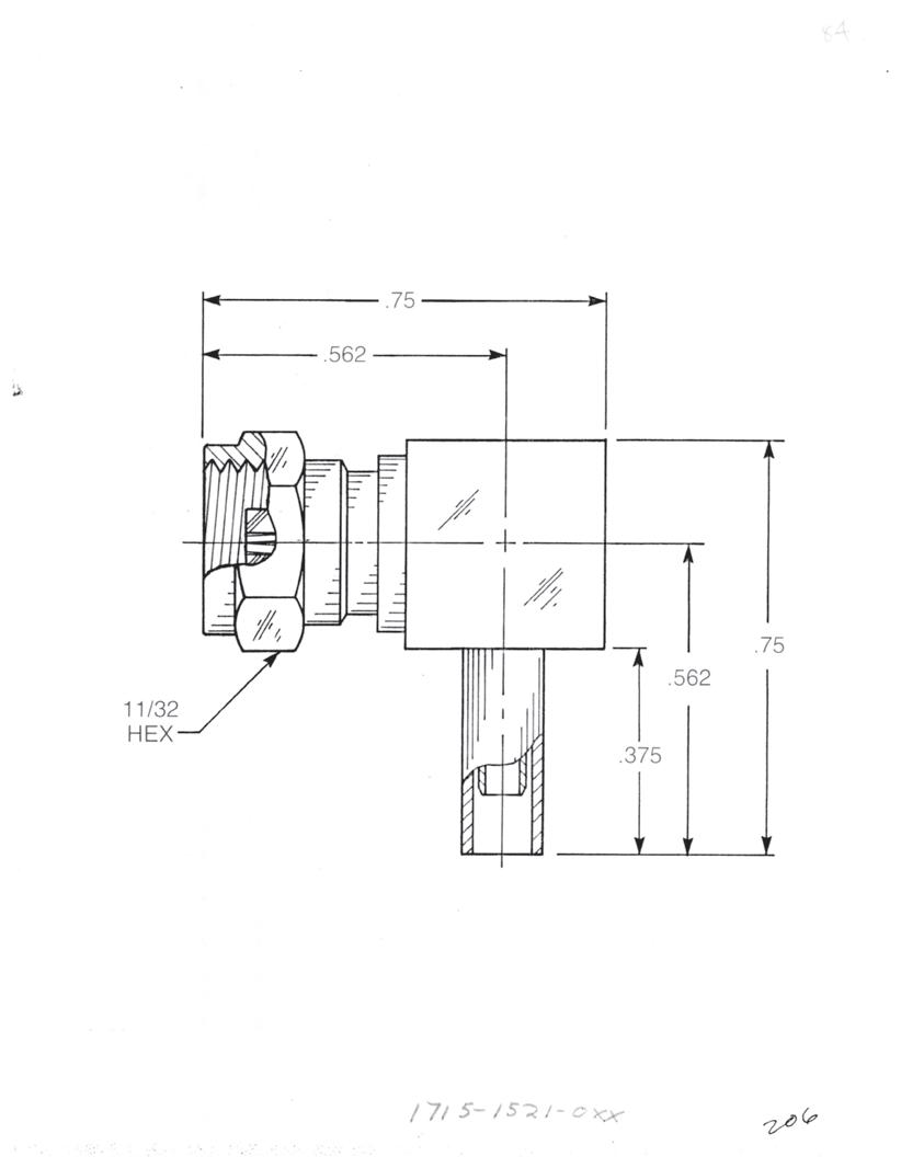
M17/94
Straight Female Cable Plug
Clamp type for flexible cable: 1702-1551-0XX (Gold-plated) 1702-7551-0XX (Nickel-plated)
Straight Female Cable Plug
Crimp type for flexible cable: 1702-1571-0XX (Gold-plated) 1702-7571-0XX (Nickel-plated)
Right Angle Female Cable Plug
Clamp type for flexible cable: 1705-1551-0XX (Gold-plated) 1705-7551-0XX (Nickel-plated)
Right Angle Female Cable Plug
Crimp type for flexible cable: 1715-1521-0XX (Gold-plated) 1715-7521-0XX (Nickel-plated)
Substitute XX with the Appropriate Cable Group Below
RG62, M17/29, M17/30
6-4 75 OHM Go online for data sheets and assembly instructions. Visit www.radiall.com/AEP and enter the part number.
03 RG179,
07
04 RG180,
-A A A
for cable group 07 A
cable groups 03
04
RG59,
RG195, M17/95
Dim = 0.303
Dim = 0.375 for
and
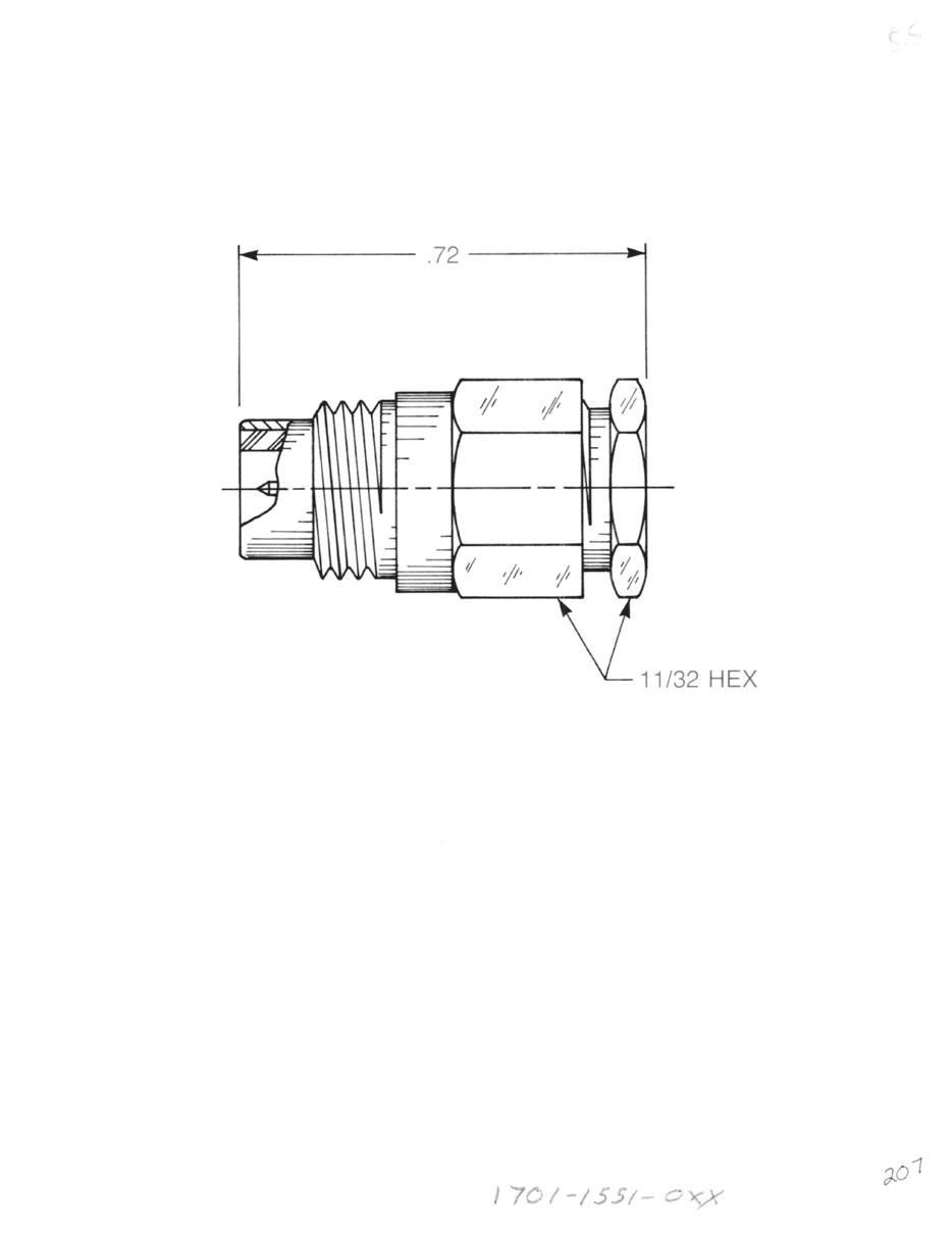
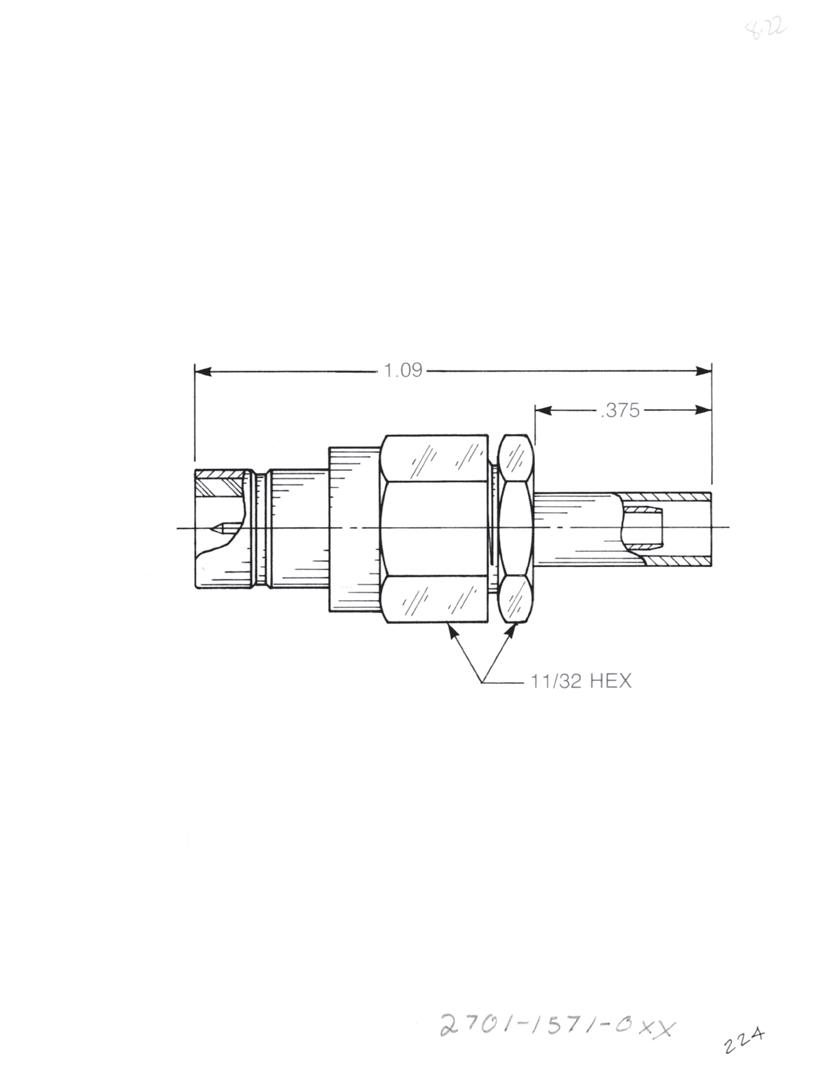
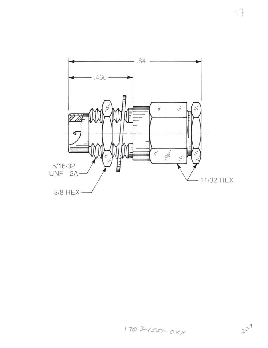
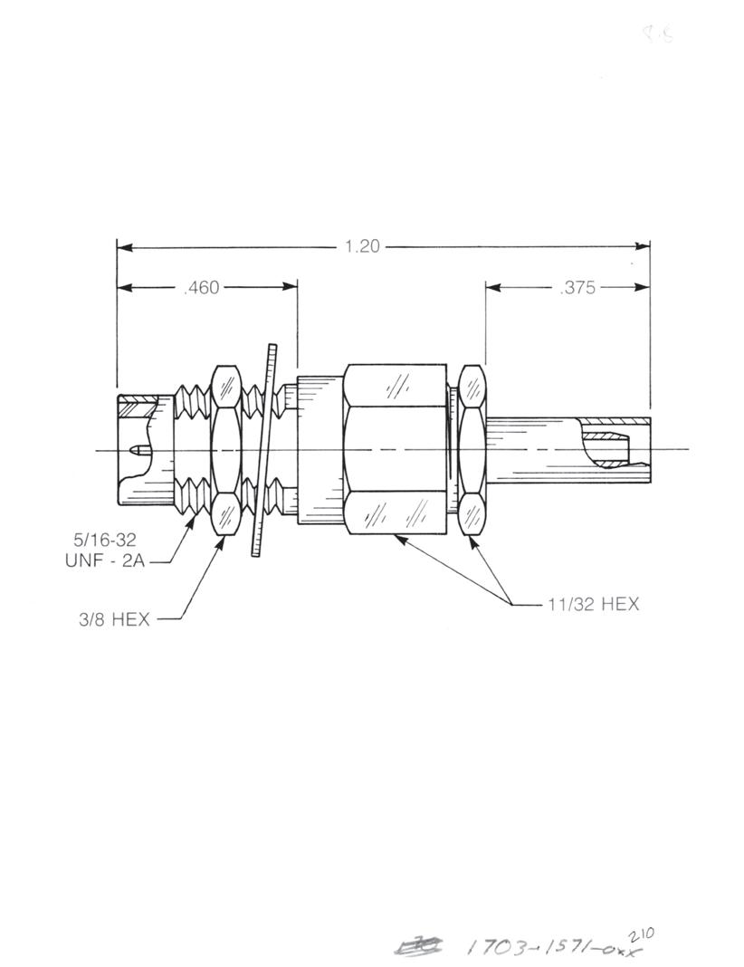
Straight Male Cable Jack
Clamp type for flexible cable: 1701-1551-0XX (Gold-plated) 1701-7551-0XX (Nickel-plated)
Straight Male Cable Jack
Crimp type for flexible cable: 1701-1571-0XX (Gold-plated) 1701-7571-0XX (Nickel-plated)
Straight Male Bulkhead Cable Jack
Clamp type for flexible cable: 1703-1551-0XX (Gold-plated) 1703-7551-0XX (Nickel-plated)
Straight Male Bulkhead Cable Jack
Crimp type for flexible cable: 1703-1571-0XX (Gold-plated) 1703-7571-0XX (Nickel-plated)
6-5 75 OHM Simplification is Our Innovation. Go online for data sheets and assembly instructions. Visit www.radiall.com/AEP and enter the part number.
Substitute
the
Below 03 RG179, M17/94 07 RG59, RG62, M17/29, M17/30 04 RG180, RG195, M17/95 -A Dim = 0.303 for cable group 07 A Dim = 0.375 for cable groups 03 and 04 A A
Jacks - Screw-On Mating
XX with
Appropriate Cable Group
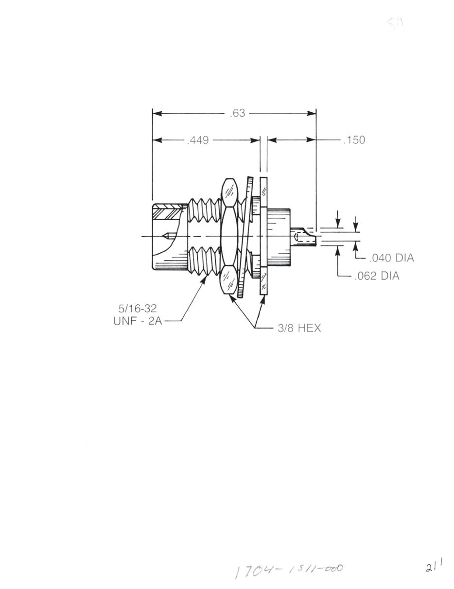
Receptacles - Screw-On Mating
Straight Male Bulkhead Jack Receptacle
• Solder pot contact
• Rear mount
1704-1511-000 (Gold-plated)
1704-7511-000 (Nickel-plated)
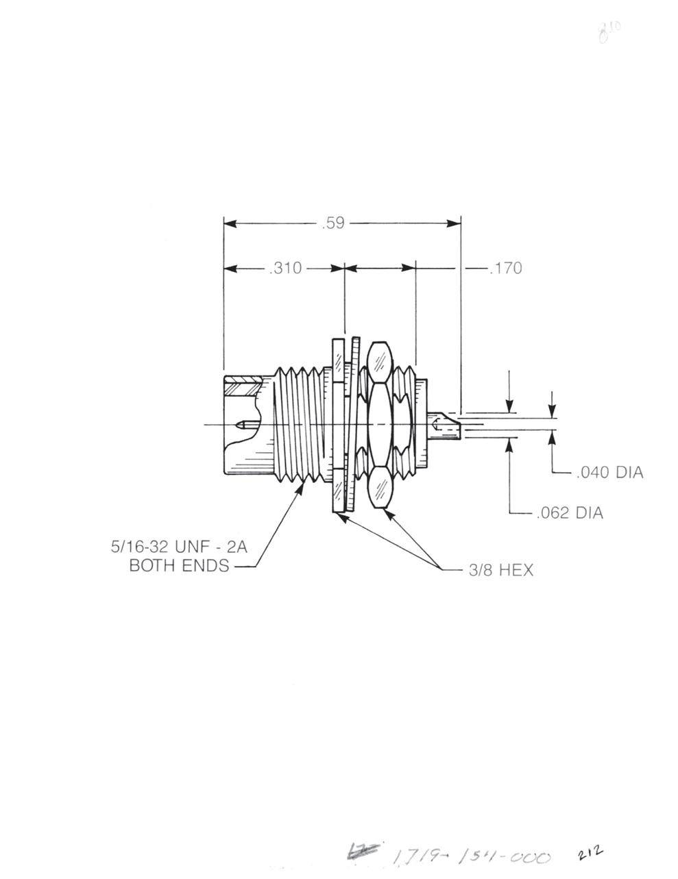
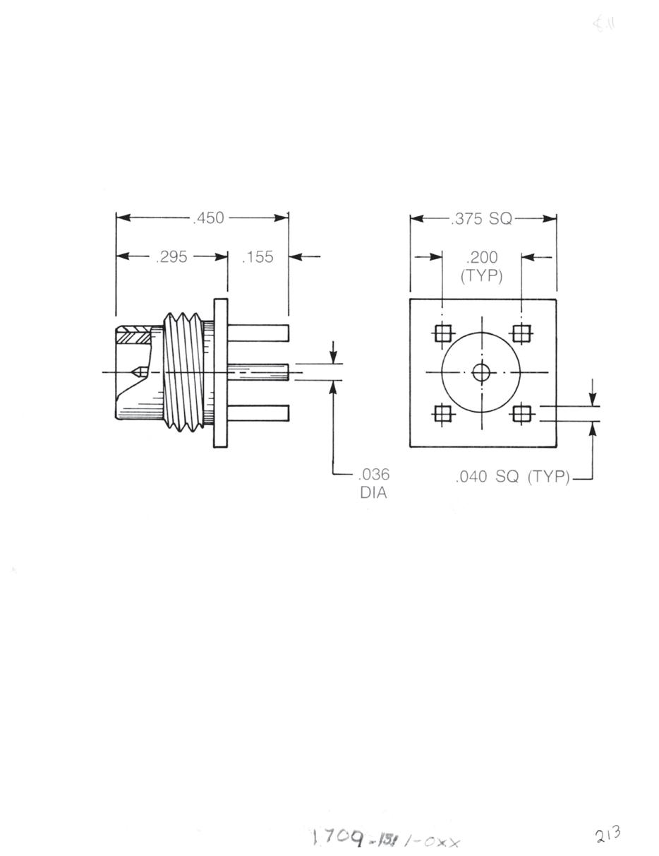
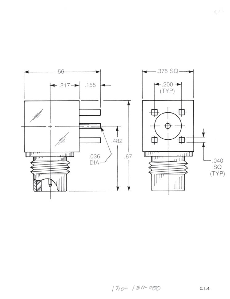
Straight Male Bulkhead Jack Receptacle
• Solder pot contact
• Front mount
1719-1511-000 (Gold-plated)
1719-7511-000 (Nickel-plated)
Straight Male PCB Receptacle
1709-1511-000 (Gold-plated)
1709-7511-000 (Nickel-plated)
Right Angle Male PCB Receptacle
1710-1511-000 (Gold-plated)
1710-7511-000 (Nickel-plated)
6-6 75 OHM Go online for data sheets and assembly instructions. Visit www.radiall.com/AEP and enter the part number.
Adapters - Screw-On Mating
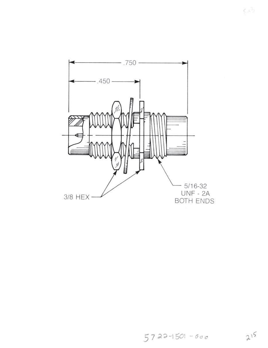
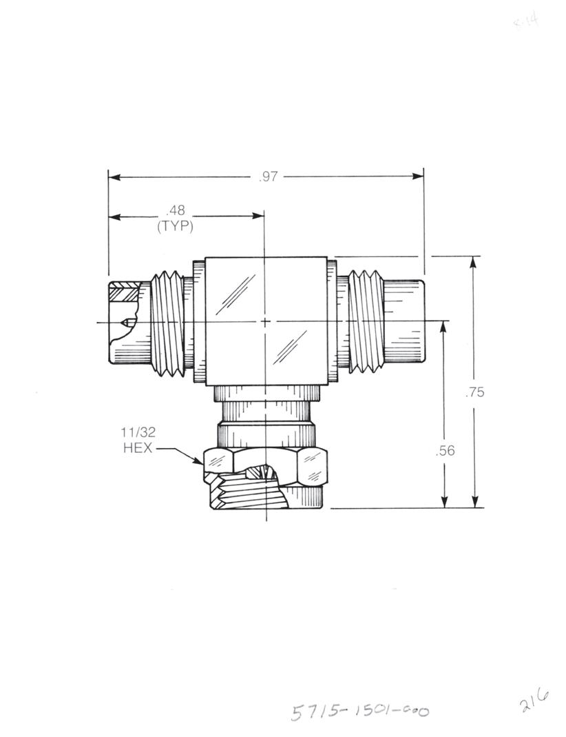
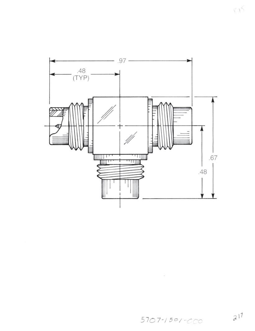
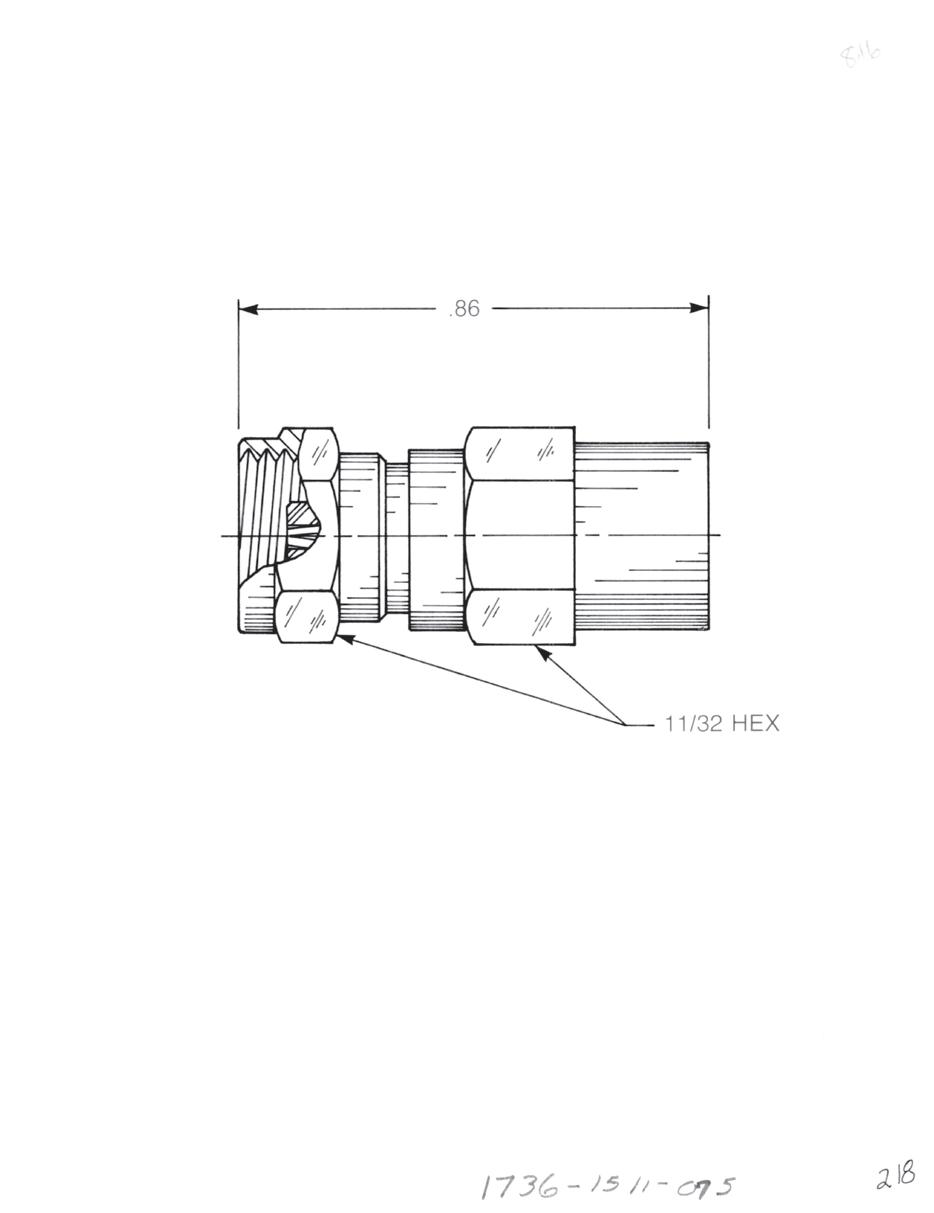
Bulkhead Mounted Straight Male Adapter
• Jack to jack
• Connects two plugs
5722-1501-000 (Gold-plated)
5722-7501-000 (Nickel-plated)
Tee Adapter (Unmatched Power Divider)
• Jack to plug to Jack
• Connects two plugs and one jack
5715-1501-000 (Gold-plated)
5715-7501-000 (Nickel-plated)
Tee Adapter (Unmatched Power Divider)
• Jack to jack to jack
• Connects three plugs
5707-1501-000 (Gold-plated)
5707-7501-000 (Nickel-plated)
Female Plug Resistive Termination (Dummy Load)
Standard resistor: 75 Ω, ½ W, 5% tolerance
1736-1511-075 (Gold-plated)
1736-7511-075 (Nickel-plated)
6-7 75 OHM Simplification is Our Innovation. Go online for data sheets and assembly instructions. Visit www.radiall.com/AEP and enter the part number.
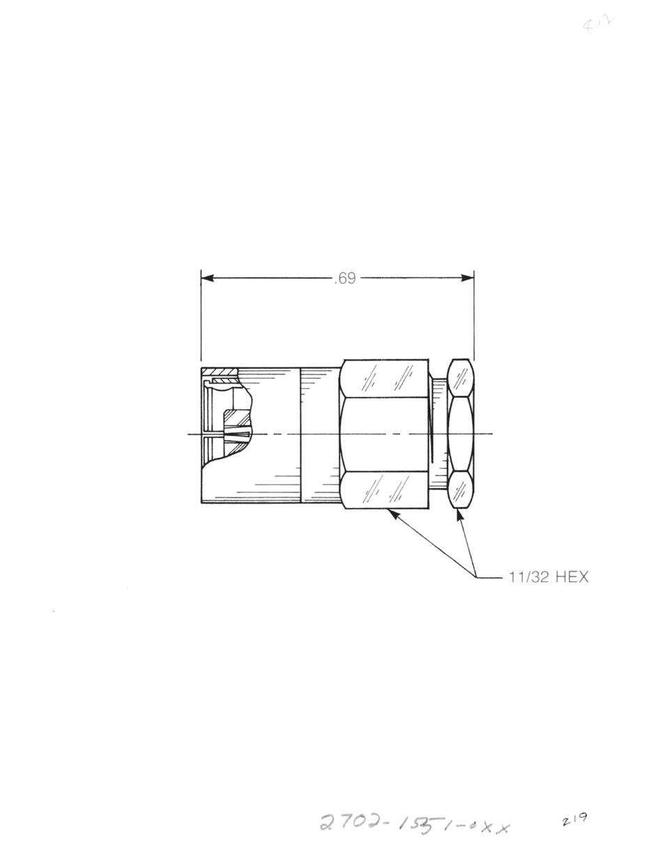
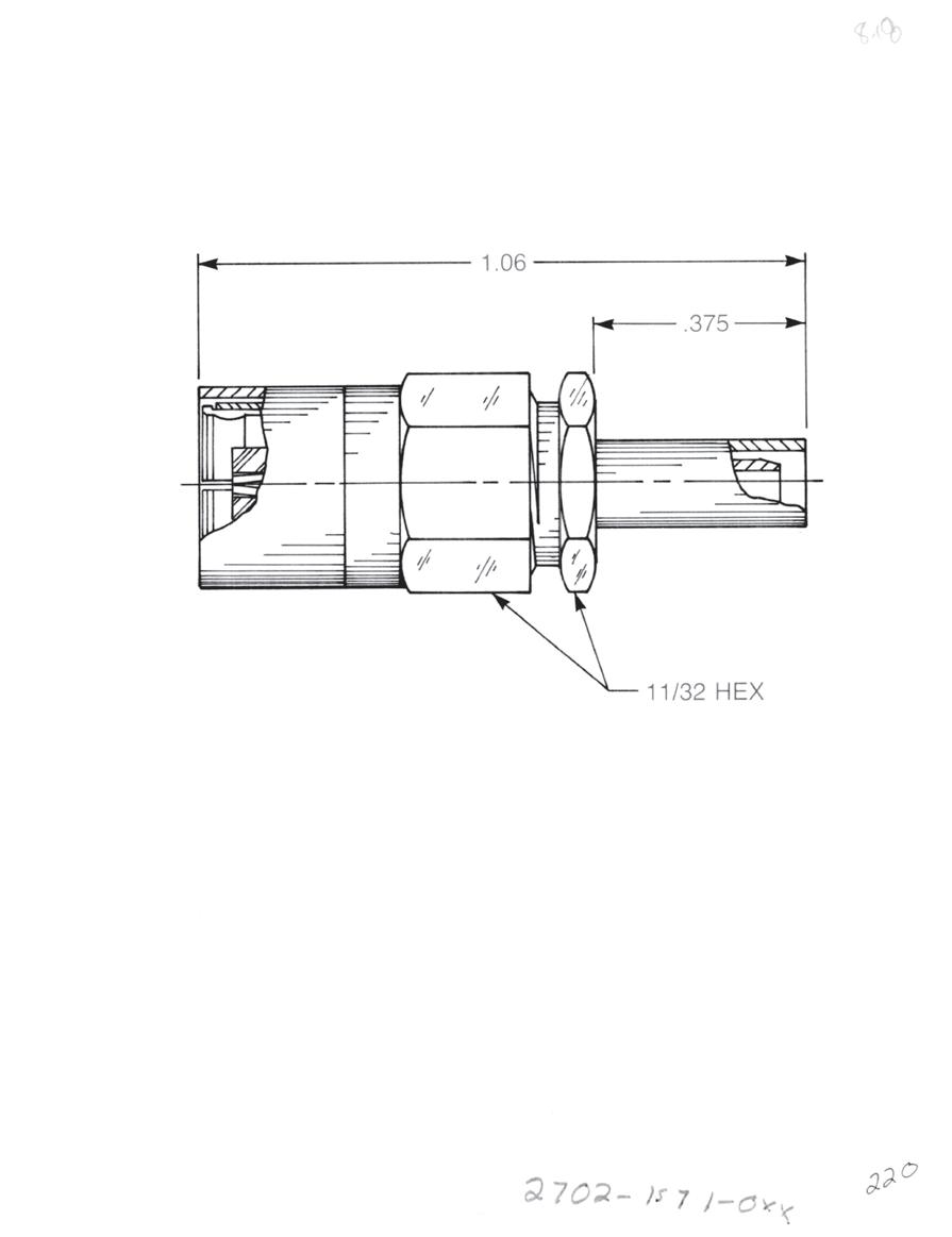
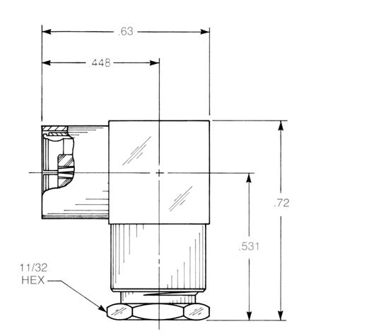
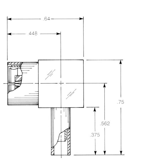
Straight Female Cable Plug
Clamp type for flexible cable:
2702-1551-0XX (Gold-plated)
2702-7551-0XX (Nickel-plated)
Straight Female Cable Plug
Crimp type for flexible cable:
2702-1571-0XX (Gold-plated)
2702-7571-0XX (Nickel-plated)
Right Angle Female Cable Plug
Clamp type for flexible cable:
2705-1551-0XX (Gold-plated)
2705-7551-0XX (Nickel-plated)
Right Angle Female Cable Plug
Crimp type for flexible cable:
2715-1521-0XX (Gold-plated)
2715-7521-0XX (Nickel-plated)
6-8 Go online for data sheets and assembly instructions. Visit www.radiall.com/AEP and enter the part number.
Substitute XX with the Appropriate Cable Group Below 03 RG179, M17/94 07 RG59, RG62, M17/29, M17/30 04 RG180, RG195, M17/95 -A Dim = 0.303 for cable group 07 A Dim = 0.375 for cable groups 03 and 04 A A
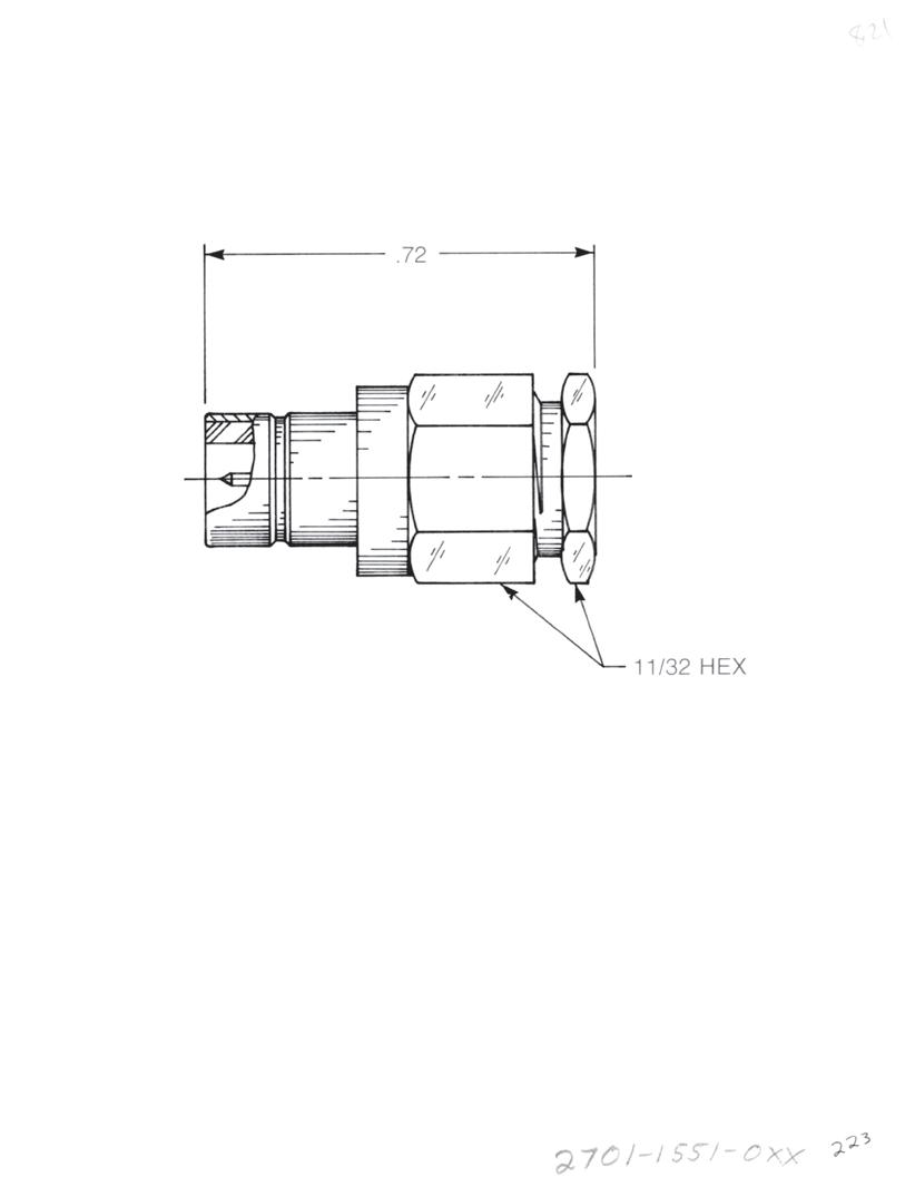
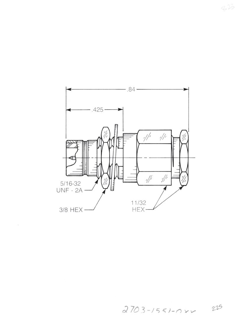
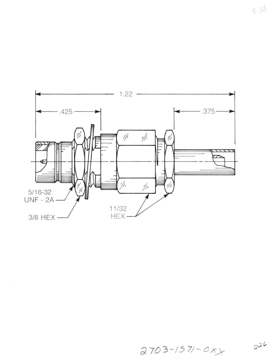
Straight Male Cable Jack
Clamp type for flexible cable:
2701-1551-0XX (Gold-plated)
2701-7551-0XX (Nickel-plated)
Straight Male Cable Jack
Crimp type for flexible cable:
2701-1571-0XX (Gold-plated)
2701-7571-0XX (Nickel-plated)
Straight Male Bulkhead Cable Jack
Clamp type for flexible cable:
2703-1551-0XX (Gold-plated)
2703-7551-0XX (Nickel-plated)
Straight Male Bulkhead Cable Jack
Crimp type for flexible cable:
2703-1571-0XX (Gold-plated)
2703-7571-0XX (Nickel-plated)
6-9 75 OHM Simplification is Our Innovation. Go online for data sheets and assembly instructions. Visit www.radiall.com/AEP and enter the part number.
Substitute XX with the Appropriate Cable Group Below 03 RG179, M17/94 07 RG59, RG62, M17/29, M17/30 04 RG180, RG195, M17/95 -A A A Dim = 0.303 for cable group 07 A Dim = 0.375 for cable groups 03 and 04
Jacks - Snap-On Mating
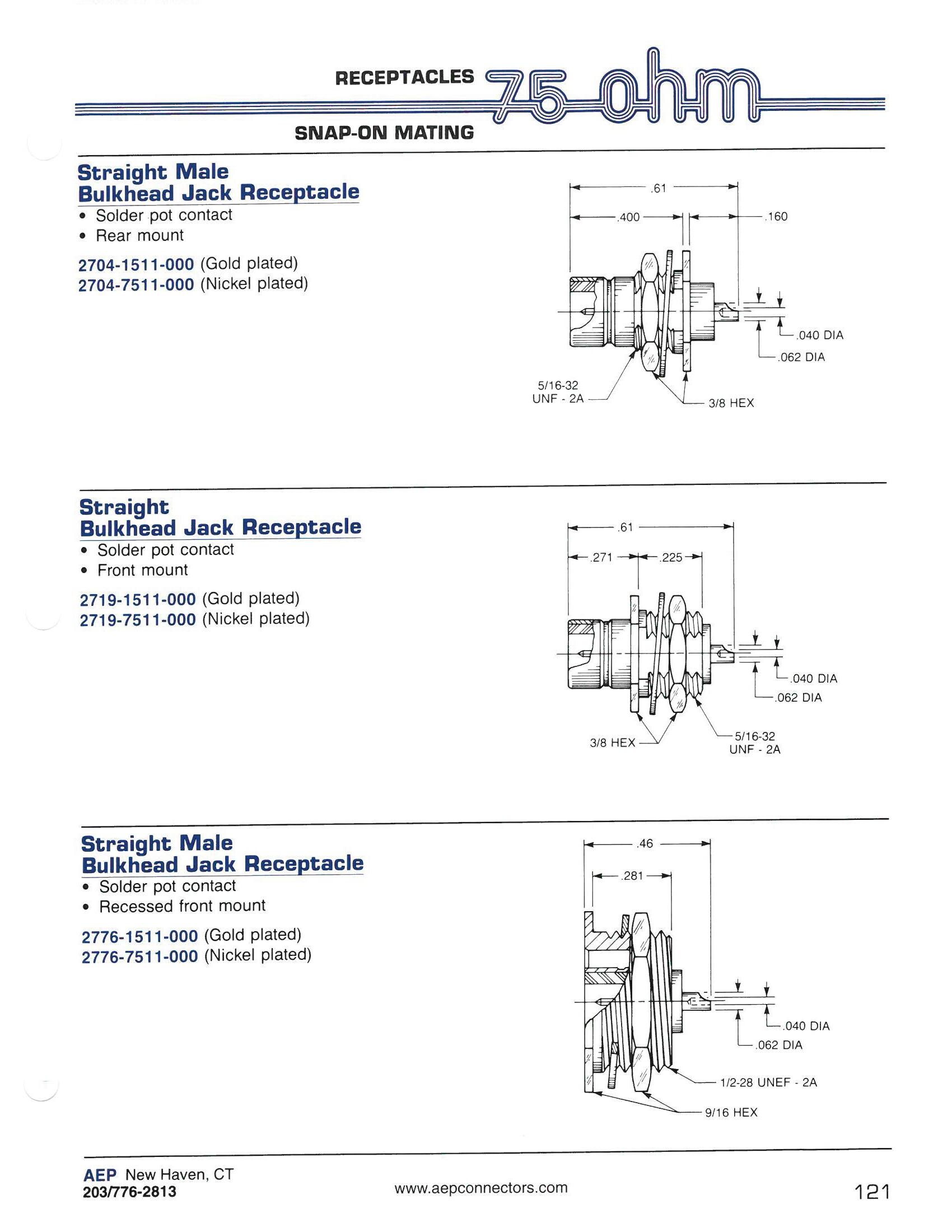
Straight Male Bulkhead Jack Receptacle
• Solder pot contact
• Rear mount
2704-1511-000 (Gold-plated)
2704-7511-000 (Nickel-plated)
Straight Bulkhead Jack Receptacle
• Solder pot contact
• Front mount
2719-1511-000 (Gold-plated)
2719-7511-000 (Nickel-plated)
Straight Male Bulkhead Jack Receptacle
• Solder pot contact
• Recessed front mount
2776-1511-000 (Gold-plated)
2776-7511-000 (Nickel-plated)
6-10 Go online for data sheets and assembly instructions. Visit www.radiall.com/AEP and enter the part number.
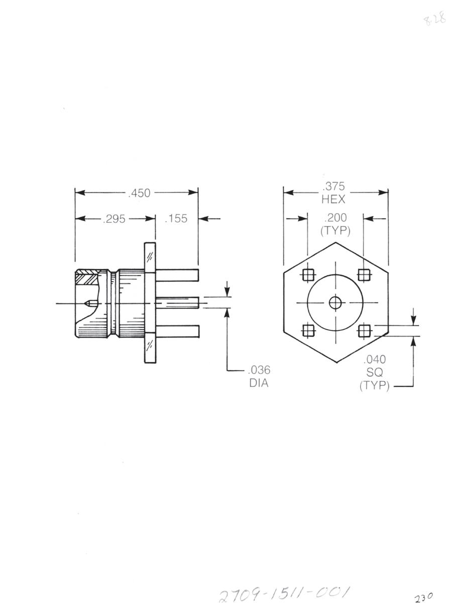
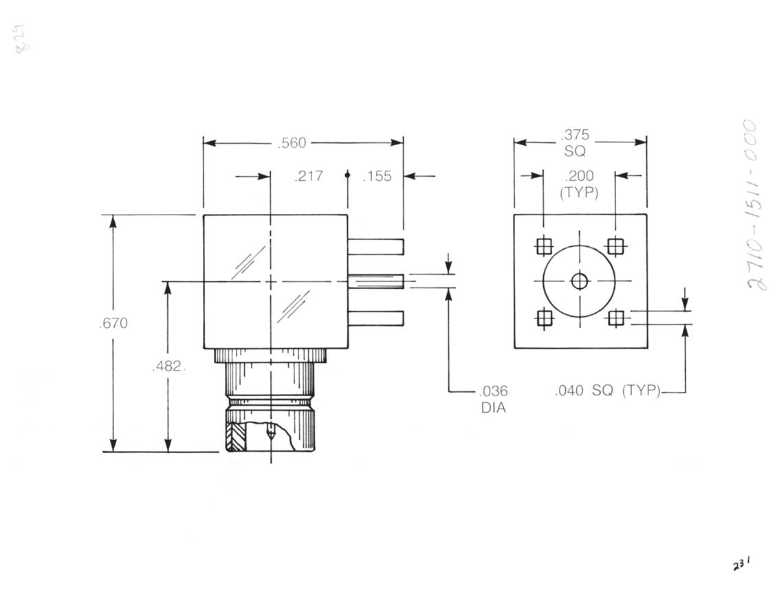
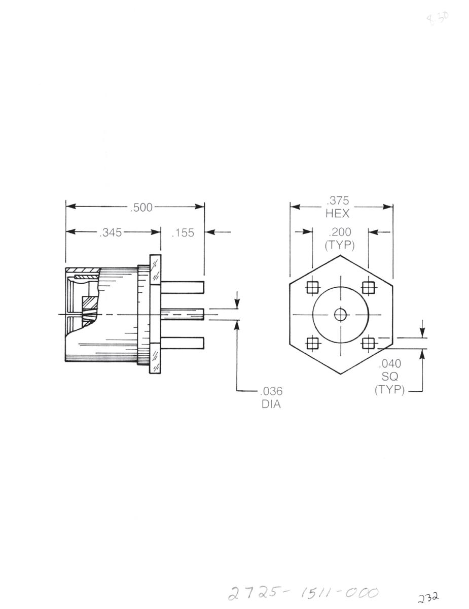
Straight Male Jack PCB Receptacle
2709-1511-001 (Gold-plated)
2709-7511-001 (Nickel-plated)
Right Angle Male Jack PCB Receptacle
2710-1511-000 (Gold-plated)
2710-7511-000 (Nickel-plated)
Straight Female Plug PCB Receptacle
2725-1511-000 (Gold-plated)
2725-7511-000 (Nickel-plated)
6-11 75 OHM Simplification
Go online for data sheets and assembly instructions. Visit www.radiall.com/AEP and enter the part number.
is Our Innovation.

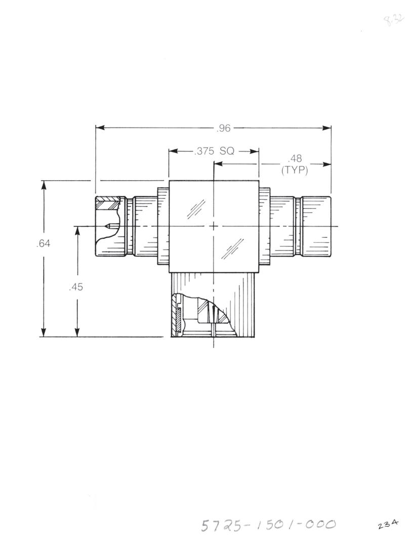
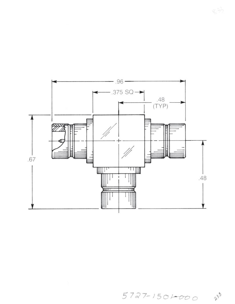
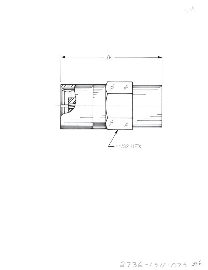
Bulkhead Mounted Straight Male
• Jack to jack adapter
• Connects two plugs
5732-1501-000 (Gold-plated)
5732-7501-000 (Nickel-plated)
Tee Adapter (Unmatched Power Divider)
• Jack to plug to jack
• Connects two plugs and one jack
5725-1501-000 (Gold-plated)
5725-7501-000 (Nickel-plated)
Tee Adapter (Unmatched Power Divider)
• Jack to jack to jack
• Connects three plugs
5727-1501-000 (Gold-plated)
5727-7501-000 (Nickel-plated)
Female Plug Resistive Termination (Dummy Load)
Standard resistor: 75 Ω, ½ W, 5% tolerance
2736-1511-075 (Gold-plated)
2736-7511-075 (Nickel-plated)
6-12 Go online for data sheets and assembly instructions. Visit www.radiall.com/AEP and enter the part number.
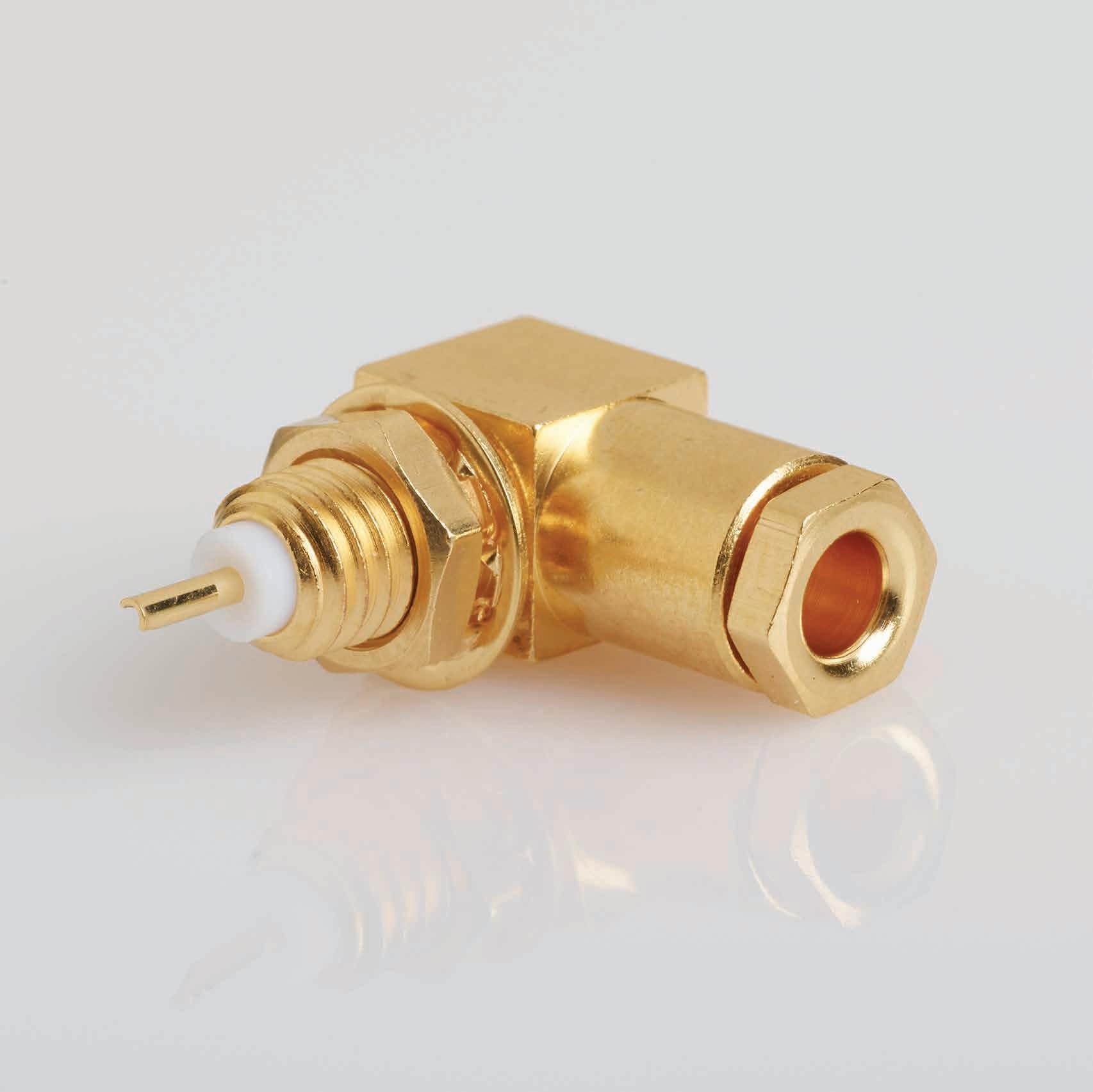
CABLE TERMINATIONS
SIMPLIFICATION IS OUR INNOVATON Visit www.radiall.com for more information. SECTION 7
7-1 Simplification is Our Innovation. Go online for data sheets and assembly instructions. Visit www.radiall.com/AEP and enter the part number. Cable Terminations 124 SECTION 7 TABLE OF CONTENTS
CABLE TERMINATIONS
Cable Terminations
Some applications require that a signal or cable core be fed through a bulkhead or into a P.C. board, but do not need the option of disconnecting the cable.
In these cases, a cable termination provides a method of securely anchoring the cable mechanically and electrically. In addition, considerable expense can be saved compared with the use of a pair of connectors.
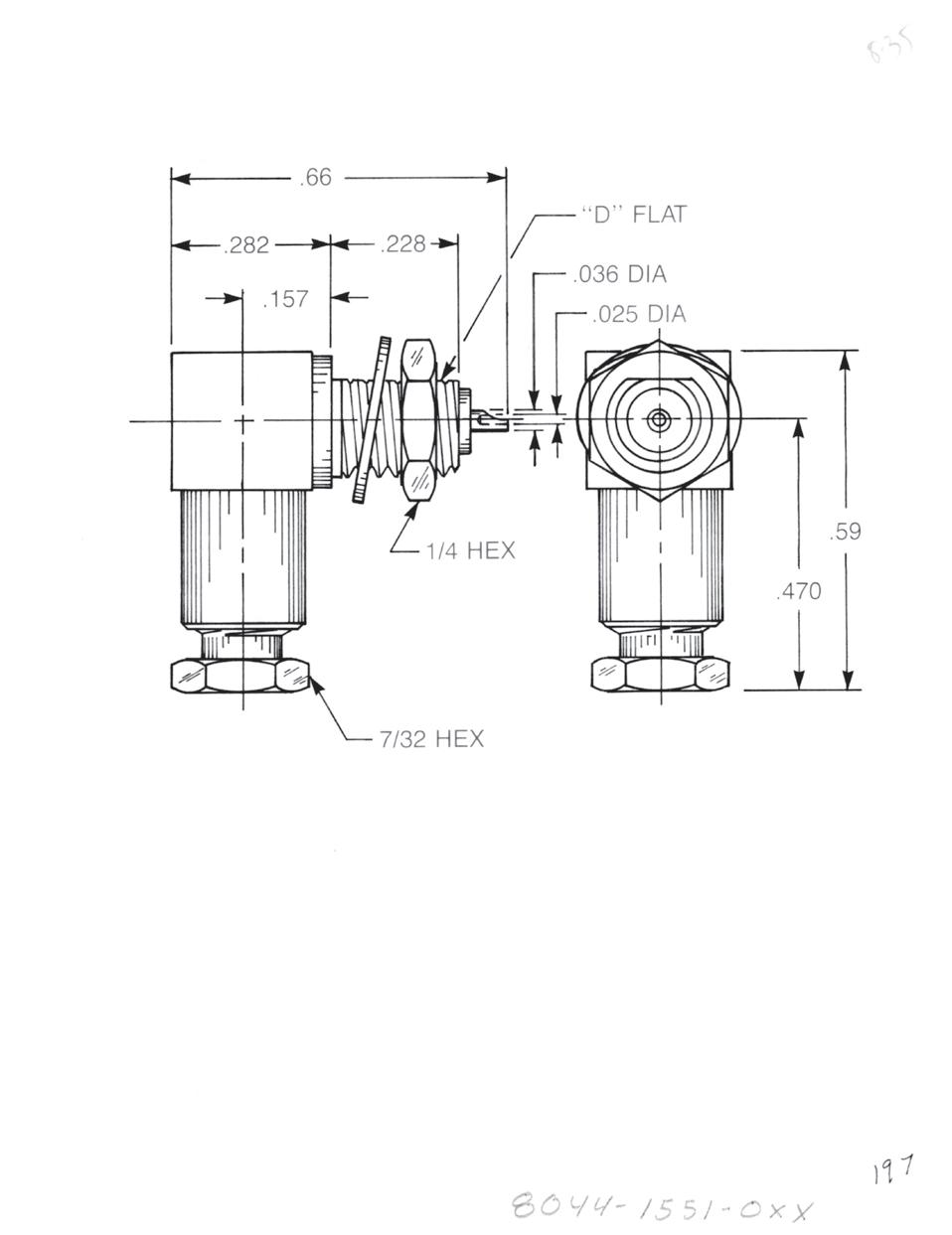
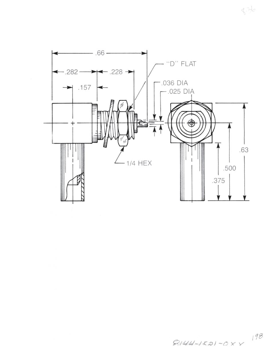
Bulkhead Mounted Right Angle Cable Termination
Clamp type for flexible cable: 8044-1551-0XX (Gold-plated) 8044-7551-0XX (Nickel-plated)
Solder-clamp for semi-rigid cable: 8044-1541-0XX (Gold-plated) 8044-7541-0XX (Nickel-plated)
Bulkhead Mounted Right Angle Cable Termination
Crimp type for flexible cable: 8144-1521-0XX (Gold-plated) 8144-7521-0XX (Nickel-plated)
Substitute XX with the Appropriate Cable Group Below
02 RG178, RG196, M17/93, M17/169
03 RG174, RG179, RG316, M17/113, M17/119, M17/172, M17/173
05 RG178DS, RG196DS
09 0.141˝ semi-rigid, RG402, M17/130
10 0.085˝ semi-rigid, RG405, M17/133
19 RG174DS, RG316DS, M17/152, Times RD316
7-2
Go online for data sheets and assembly instructions. Visit www.radiall.com/AEP and enter the part number.
Cable Terminations
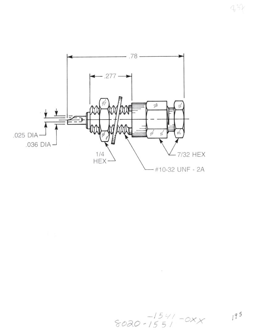
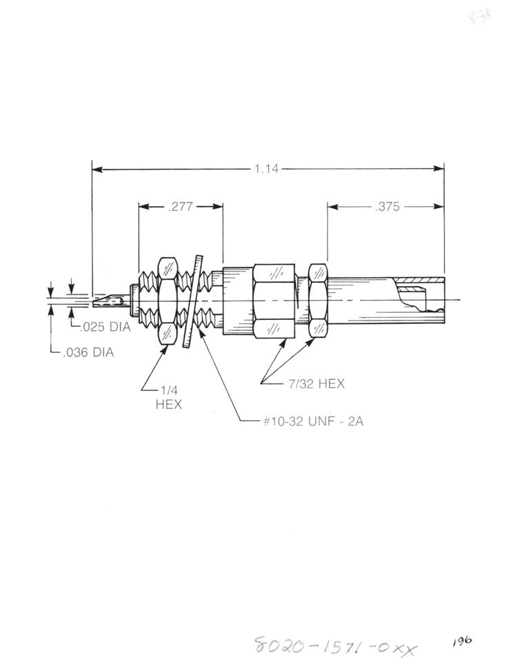
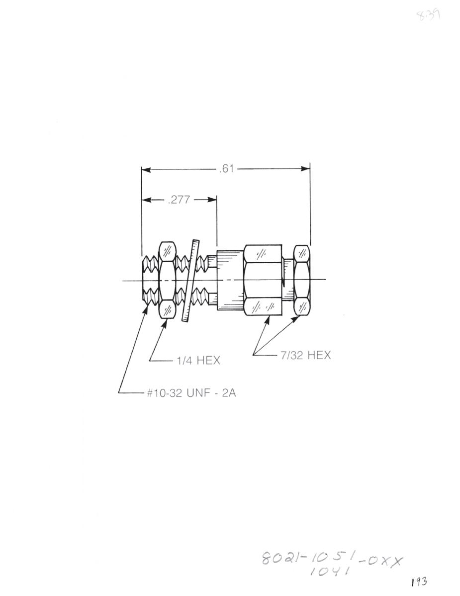
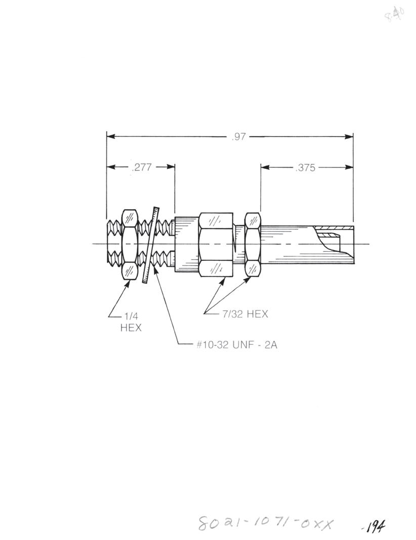
Bulkhead Mounted Straight Cable Termination
Clamp type for flexible cable: 8020-1551-0XX (Gold-plated) 8020-7551-0XX (Nickel-plated)
Solder-clamp for semi-rigid cable: 8020-1541-0XX (Gold-plated)
8020-7541-0XX (Nickel-plated)
Bulkhead Mounted Straight Cable Termination
Crimp type for flexible cable: 8020-1571-0XX (Gold-plated)
8020-7571-0XX (Nickel-plated)
Bulkhead Mounted Straight Cable Feedthrough
• Feeds cable dielectric and center conductor through bulkhead
Clamp type for flexible cable: 8021-1051-0XX (Gold-plated) 8021-7051-0XX (Nickel-plated)
Solder-clamp for semi-rigid cable: 8021-1041-0XX (Gold-plated) 8021-7041-0XX (Nickel-plated)
Bulkhead Mounted Straight Cable Feedthrough
• Feeds cable dielectric and center conductor through bulkhead
Crimp type for flexible cable: 8021-1071-0XX (Gold-plated) 8021-7071-0XX (Nickel-plated)
Substitute XX with the Appropriate Cable Group Below RG178, RG196, M17/93, M17/169
RG174, RG179, RG316, M17/113, M17/119, M17/172, M17/173
0.141˝ semi-rigid, RG402, M17/130
semi-rigid, RG405, M17/133
RG174DS, RG316DS, M17/152, Times RD316
CABLE TERMINATIONS
7-3
Go online for data sheets and assembly instructions. Visit www.radiall.com/AEP and enter the part number.
Simplification is Our Innovation.
09
03
10
05
19
0.085˝
RG178DS, RG196DS
CABLE TERMINATIONS
Cable Terminations
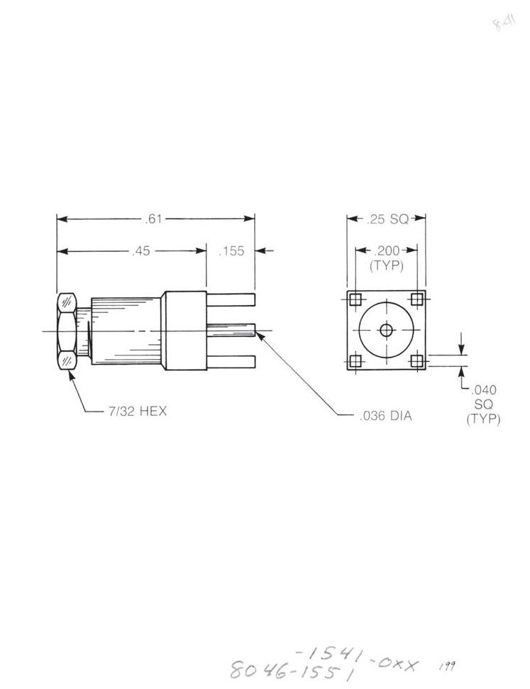
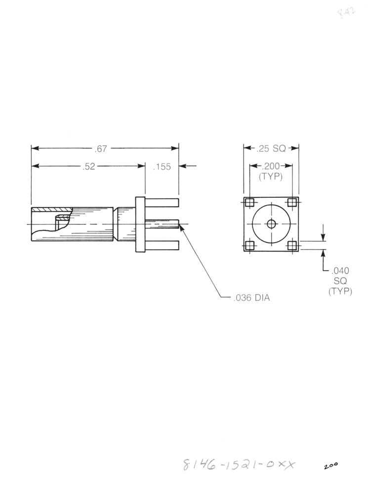
Straight PCB Cable Termination
Clamp type for flexible cable: 8046-1551-0XX (Gold-plated) 8046-7551-0XX (Nickel-plated)
Solder-clamp for semi-rigid cable: 8046-1541-0XX (Gold-plated) 8046-7541-0XX (Nickel-plated)

Straight PCB Cable Termination
Crimp type for flexible cable: 8146-1521-0XX (Gold-plated) 8146-7521-0XX (Nickel-plated)
Right Angle PCB Cable Termination
Clamp type for flexible cable: 8045-1551-0XX (Gold-plated) 8045-7551-0XX (Nickel-plated)
Solder-clamp for semi-rigid cable: 8045-1541-0XX (Gold-plated) 8045-7541-0XX (Nickel-plated)
Right Angle PCB Cable Termination
Crimp type for flexible cable: 8145-1521-0XX (Gold-plated) 8145-7521-0XX (Nickel-plated)
Substitute XX with the Appropriate Cable Group Below
02 RG178, RG196, M17/93, M17/169
03 RG174, RG179, RG316, M17/113, M17/119, M17/172, M17/173
05 RG178DS, RG196DS
09 0.141˝ semi-rigid, RG402, M17/130
10 0.085˝ semi-rigid, RG405, M17/133
19 RG174DS, RG316DS, M17/152, Times RD316
7-4
Go online for data sheets and assembly instructions. Visit www.radiall.com/AEP and enter the part number.
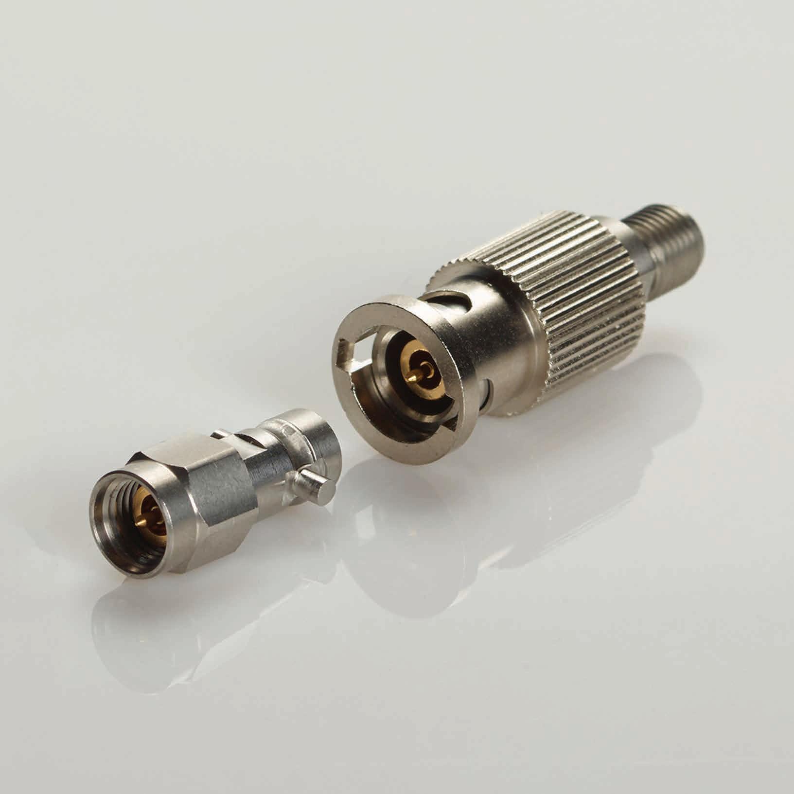
SIMPLIFICATION IS OUR INNOVATON Visit www.radiall.com for more information. SECTION 8 QCD
8-1 Simplification is Our Innovation. Go online for data sheets and assembly instructions. Visit www.radiall.com/AEP and enter the part number. QCD
124 SECTION 8 TABLE OF CONTENTS
(Quick Connect-Disconnect)
QCD
QCD (Quick Connect-Disconnect) provides a 26 GHz bayonet to SMA connector solution that reduces time for setup, reduces calibration steps, provides a quick test setup and aids in preserving test cable durability. The QCD is a perfect time saving solution for high density, high-count test environments.
Features
• 50 Ω
• DC to 26.5 GHz
• Low VSWR and insertion loss
• 5,000 matings minimum
• Reduces time for setup, calibration and testing
• Reduces need for additional calibration
• Perfect for high mating/ unmating applications
• Bayonet coupling for easy mating
• Extended life of test cables
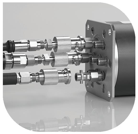
MATERIALS:
Body parts: Stainless steel
Contacts: Beryllium copper
Insulators: PTFE
Gaskets: Silicone rubber
FINISH:
Body: Passivated
Center contacts: NPGR
Outer contact: Gold 0.2 over nickel 2
ELECTRICAL:
Impedance: 50 Ω
Frequency range: 0-26 GHz
VSWR: 1.1+0.0000×f (GHz) max
Insertion loss: 0.06√(f ) (GHz) dB max
RF leakage: -[ -f (GHz)] dB max
Voltage rating: 500 Veff max
Dielectric withstanding voltage: 1,000 Veff min
Insulation resistance: 5,000 MΩ min
MECHANICAL:
5913-2503-000
Center contact retention:
Axial force – Mating end: 2.8 N min
Axial force – Opposite end: N min
Torque: Ncm min
Recommended torque:
Mating: SMA 0 Ncm
Mating life: 5,000 cycles min
Weight: 12.3520 g
5914-9503-000
Center contact retention:
Axial force – Mating end: 27 N min
Axial force – Opposite end: 27 N min
Torque: 2.8 Ncm min
Recommended torque:
Mating: SMA 110 Ncm
Mating life: 5,000 cycles min
Weight: 4.2470 g
ENVIRONMENTAL:
Operating: -65°C/+165°C
Hermetic seal: Atm cm 3/s panel leakage
8-2
Go online for data sheets and assembly instructions. Visit www.radiall.com/AEP and enter the part number.
N A
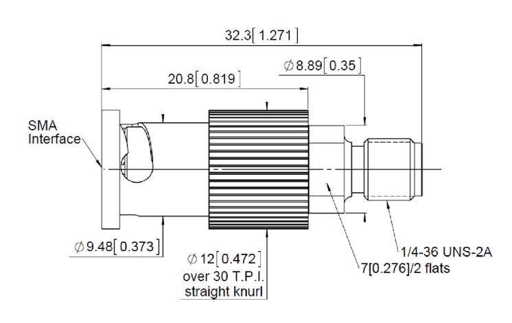
SMA Straight Flange Floating Jack to QCD Plug Adapter
5913-2503-000
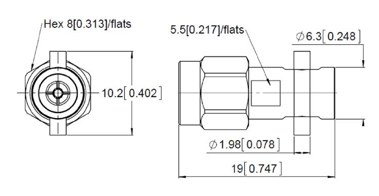
SMA Plug to Female QCD Adapter
5914-9503-000
8-3
Go online for data sheets and assembly instructions. Visit www.radiall.com/AEP and enter the part number.
QCD Simplification is Our Innovation.
NOTES
Go online for data sheets and assembly instructions. Visit www.radiall.com/AEP and enter the part number.
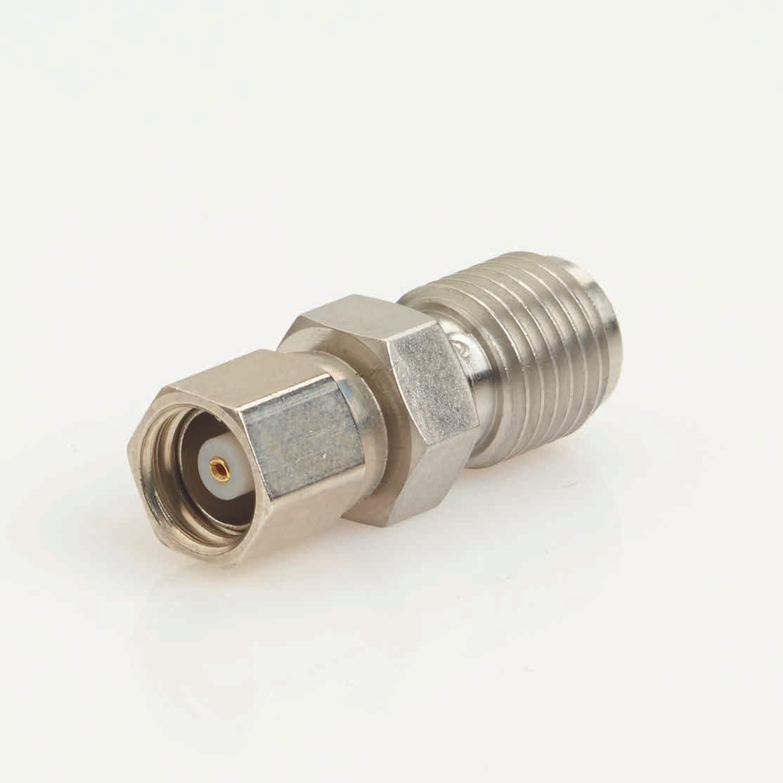
ADAPTERS
SIMPLIFICATION IS OUR INNOVATON Visit www.radiall.com for more information. SECTION 9
9-1 Simplification is Our Innovation. Go online for data sheets and assembly instructions. Visit www.radiall.com/AEP and enter the part number. SMB to SMC 9-2 BNC to Subminiature 9-3 N to Subminiature 9-4 TNC to Subminiature 9-5 SECTION 9 TABLE OF CONTENTS
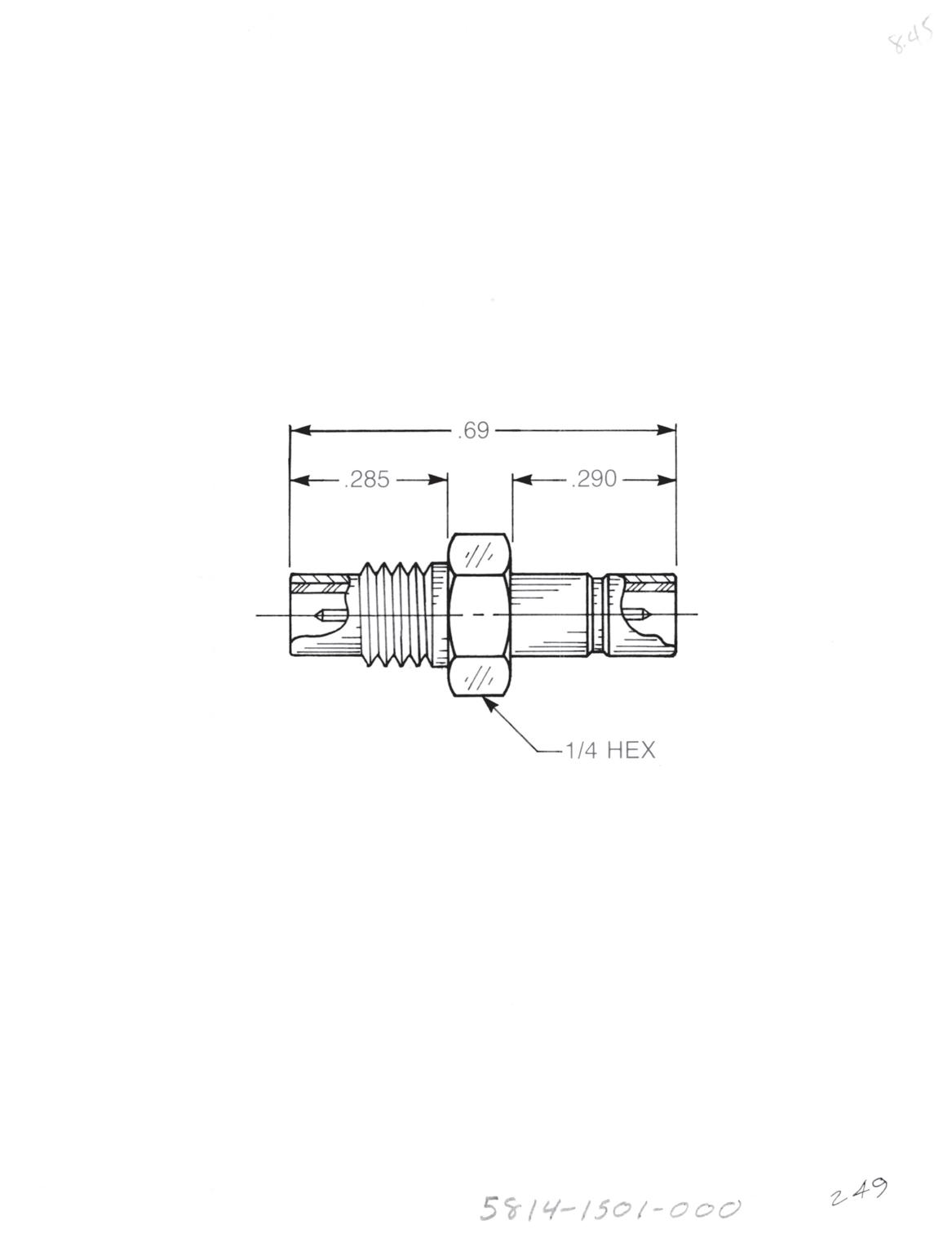
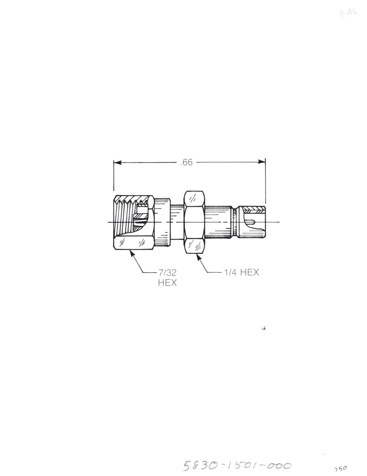
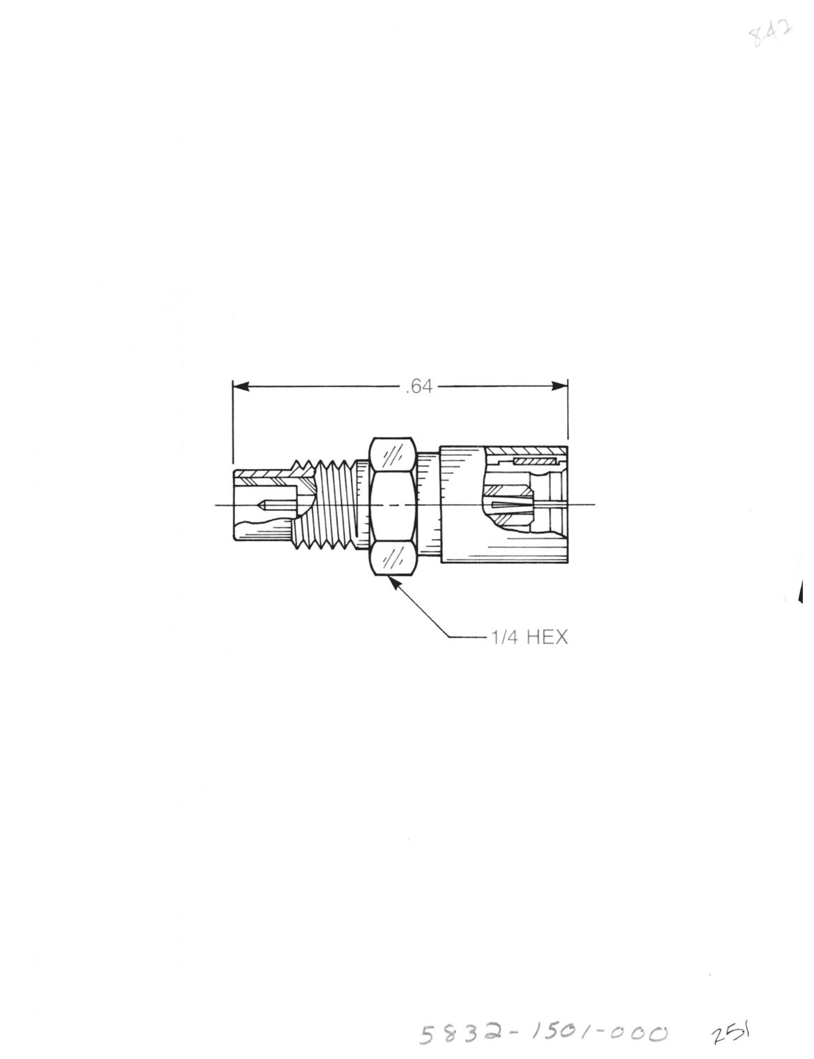
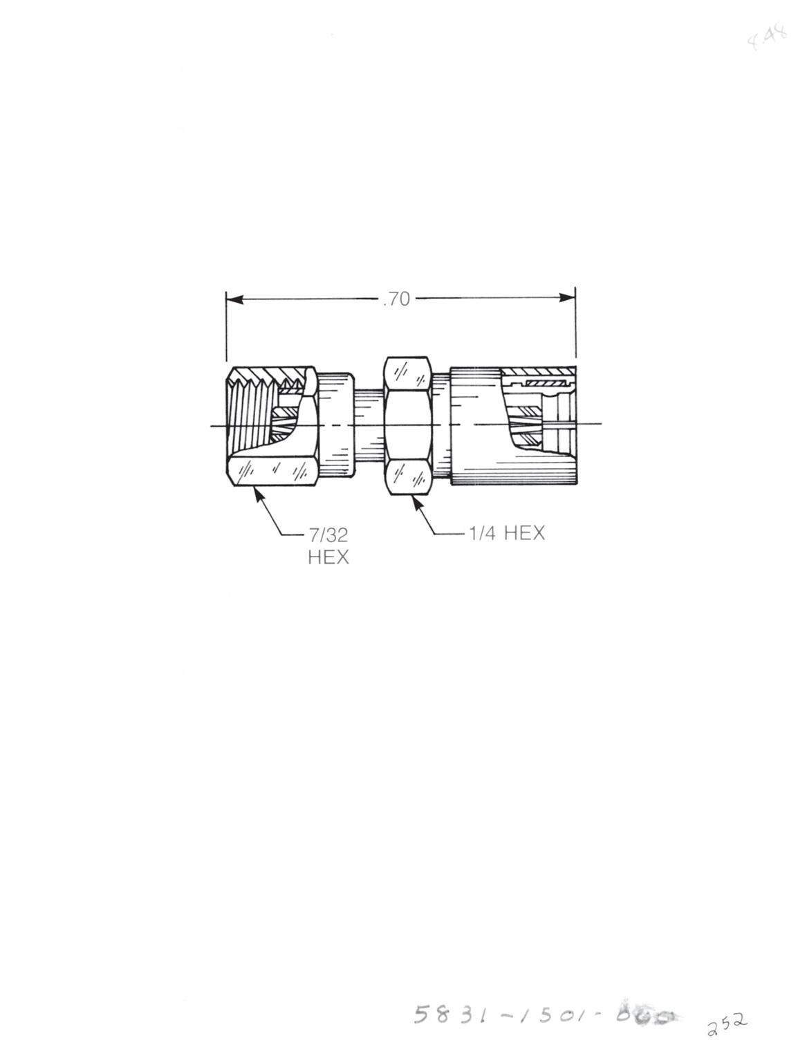
SMB Male Jack to SMC Male Jack
• Connects SMB plug to SMC plug
5814-1501-000 (Gold-plated)
5814-7501-000 (Nickel-plated)
SMB Male Jack to SMC Female Plug
• Connects SMB plug to SMC jack
5830-1501-000 (Gold-plated)
5830-7501-000 (Nickel-plated)
SMB Female Plug to SMC Male Jack
• Connects SMB jack to SMC plug
5832-1501-000 (Gold-plated)
5832-7501-000 (Nickel-plated)
5831-7501-000 (Nickel-plated) Between Series - SMB to SMC
SMB Female Plug to SMC Female Plug
• Connects SMB jack to SMC jack
5831-1501-000 (Gold-plated)
9-2 Go online for data sheets and assembly instructions. Visit www.radiall.com/AEP and enter the part number.
Between Series - BNC to Subminiature
BNC Plug
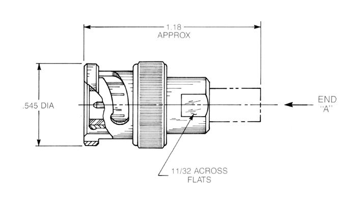
BNC Bulkhead Jack
• Front mount
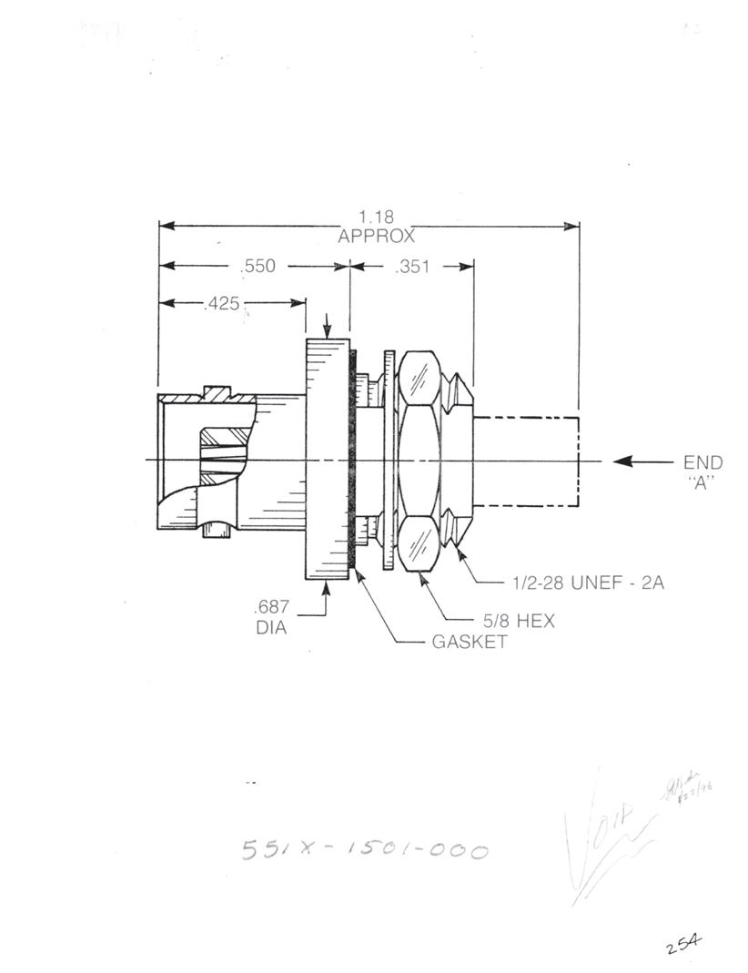
BNC Bulkhead Jack
• Rear mount
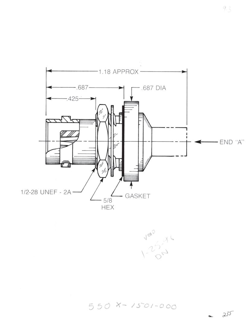
SMC MALE JACK
SMC FEMALE PLUG
SMB MALE JACK
SMB FEMALE PLUG
75 OHM SCREW-ON MALE JACK
75 OHM SCREW-ON FEMALE PLUG
75 OHM SNAP-ON MALE JACK
75 OHM SNAP-ON FEMALE PLUG
SMC MALE JACK
SMC FEMALE PLUG
SMB MALE JACK
SMB FEMALE PLUG
75 OHM SCREW-ON MALE JACK
75 OHM SCREW-ON FEMALE PLUG
75 OHM SNAP-ON MALE JACK
75 OHM SNAP-ON FEMALE PLUG
SMC MALE JACK
SMC FEMALE PLUG
SMB MALE JACK
SMB FEMALE PLUG
75 OHM SCREW-ON MALE JACK
75 OHM SCREW-ON FEMALE PLUG
75 OHM SNAP-ON MALE JACK
75 OHM SNAP-ON FEMALE PLUG
5402-1501-000 (Gold-plated)
5402-7501-000 (Nickel-plated)
5403-1501-000 (Gold-plated)
5403-7501-000 (Nickel-plated)
5404-1501-000 (Gold-plated)
5404-7501-000 (Nickel-plated)
5405-1501-000 (Gold-plated)
5405-7501-000 (Nickel-plated)
5406-1501-000 (Gold-plated)
5406-7501-000 (Nickel-plated)
5407-1501-000 (Gold-plated)
5407-7501-000 (Nickel-plated)
5408-1501-000 (Gold-plated)
5408-7501-000 (Nickel-plated)
5409-1501-000 (Gold-plated)
5409-7501-000 (Nickel-plated)
5510-1501-000 (Gold-plated)
5510-7501-000 (Nickel-plated)
5511-1501-000 (Gold-plated)
5511-7501-000 (Nickel-plated)
5512-1501-000 (Gold-plated)
5512-7501-000 (Nickel-plated)
5513-1501-000 (Gold-plated)
5513-7501-000 (Nickel-plated)
5514-1501-000 (Gold-plated)
5514-7501-000 (Nickel-plated)
5515-1501-000 (Gold-plated)
5515-7501-000 (Nickel-plated)
5516-1501-000 (Gold-plated)
5516-7501-000 (Nickel-plated)
5517-1501-000 (Gold-plated)
5517-7501-000 (Nickel-plated)
5502-1501-000 (Gold-plated)
5502-7501-000 (Nickel-plated)
5503-1501-000 (Gold-plated)
5503-7501-000 (Nickel-plated)
5504-1501-000 (Gold-plated)
5504-7501-000 (Nickel-plated)
5505-1501-000 (Gold-plated)
5505-7501-000 (Nickel-plated)
5506-1501-000 (Gold-plated)
5506-7501-000 (Nickel-plated)
5507-1501-000 (Gold-plated)
5507-7501-000 (Nickel-plated)
5508-1501-000 (Gold-plated)
5508-7501-000 (Nickel-plated)
5509-1501-000 (Gold-plated)
5509-7501-000 (Nickel-plated)
9-3 ADAPTERS Simplification
Go online for data sheets and assembly instructions. Visit www.radiall.com/AEP and enter the part number.
is Our Innovation.
END “A” CONFIGURATION
END “A” CONFIGURATION
END “A” CONFIGURATION
Between Series - N to Subminiature
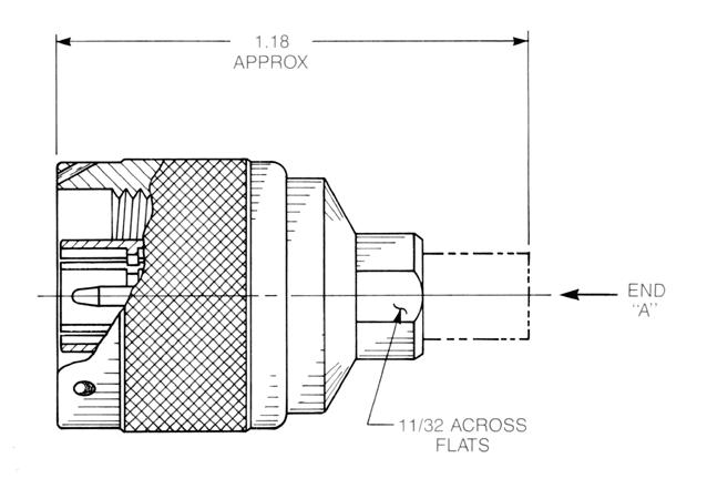
N Bulkhead Jack
• Front mount
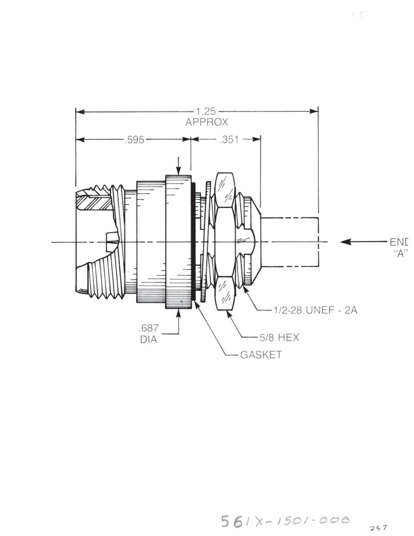
N Bulkhead Jack
• Rear mount
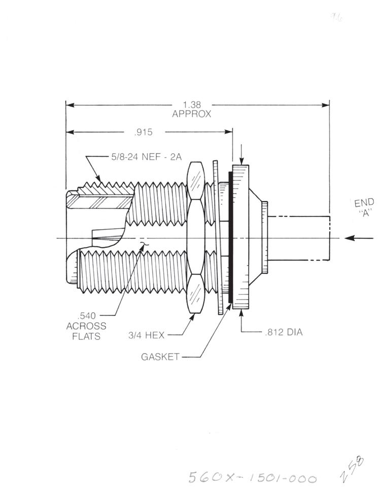
SMC MALE JACK
SMC FEMALE PLUG
SMB MALE JACK
SMB FEMALE PLUG
75 OHM SCREW-ON MALE JACK
75 OHM SCREW-ON FEMALE PLUG
75 OHM SNAP-ON MALE JACK
75 OHM SNAP-ON FEMALE PLUG
SMC MALE JACK
SMC FEMALE PLUG
CONFIGURATION
SMB MALE JACK
SMB FEMALE PLUG
75 OHM SCREW-ON MALE JACK
75 OHM SCREW-ON FEMALE PLUG
75 OHM SNAP-ON MALE JACK
75 OHM SNAP-ON FEMALE PLUG
SMC MALE JACK
SMC FEMALE PLUG
SMB MALE JACK
SMB FEMALE PLUG
75 OHM SCREW-ON MALE JACK
75 OHM SCREW-ON FEMALE PLUG
75 OHM SNAP-ON MALE JACK
75 OHM SNAP-ON FEMALE PLUG
5002-1501-000 (Gold-plated)
5002-7501-000 (Nickel-plated)
5003-1501-000 (Gold-plated)
5003-7501-000 (Nickel-plated)
5004-1501-000 (Gold-plated)
5004-7501-000 (Nickel-plated)
5005-1501-000 (Gold-plated)
5005-7501-000 (Nickel-plated)
5006-1501-000 (Gold-plated)
5006-7501-000 (Nickel-plated)
5007-1501-000 (Gold-plated)
5007-7501-000 (Nickel-plated)
5008-1501-000 (Gold-plated)
5008-7501-000 (Nickel-plated)
5009-1501-000 (Gold-plated)
5009-7501-000 (Nickel-plated)
5610-1501-000 (Gold-plated)
5610-7501-000 (Nickel-plated)
5611-1501-000 (Gold-plated)
5611-7501-000 (Nickel-plated)
5612-1501-000 (Gold-plated)
5612-7501-000 (Nickel-plated)
5613-1501-000 (Gold-plated)
5613-7501-000 (Nickel-plated)
5614-1501-000 (Gold-plated)
5614-7501-000 (Nickel-plated)
5615-1501-000 (Gold-plated)
5615-7501-000 (Nickel-plated)
5616-1501-000 (Gold-plated)
5616-7501-000 (Nickel-plated)
5617-1501-000 (Gold-plated)
5617-7501-000 (Nickel-plated)
5602-1501-000 (Gold-plated)
5602-7501-000 (Nickel-plated)
5603-1501-000 (Gold-plated)
5603-7501-000 (Nickel-plated)
5604-1501-000 (Gold-plated)
5604-7501-000 (Nickel-plated)
5605-1501-000 (Gold-plated)
5605-7501-000 (Nickel-plated)
5606-1501-000 (Gold-plated)
5606-7501-000 (Nickel-plated)
5607-1501-000 (Gold-plated)
5607-7501-000 (Nickel-plated)
5608-1501-000 (Gold-plated)
5608-7501-000 (Nickel-plated)
5609-1501-000 (Gold-plated)
5609-7501-000 (Nickel-plated)
9-4
Go online for data sheets and assembly instructions. Visit www.radiall.com/AEP and enter the part number.
ADAPTERS
END “A” CONFIGURATION
N
Plug
END “A”
END “A”
CONFIGURATION
Between Series - TNC to Subminiature
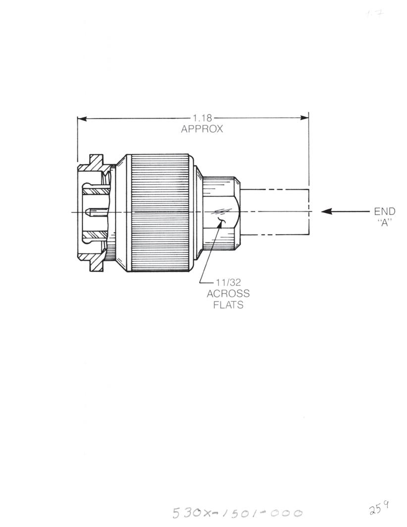
TNC Plug
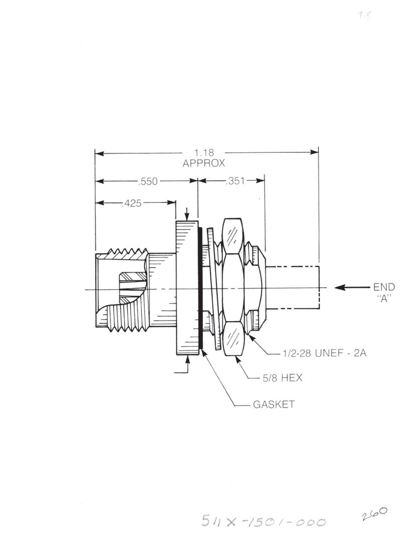
TNC Bulkhead Jack
• Front mount
TNC Bulkhead Jack
• Rear mount
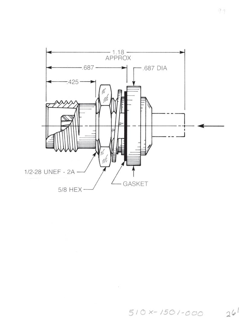
SMC MALE JACK
SMC FEMALE PLUG
SMB MALE JACK
SMB FEMALE PLUG
75 OHM SCREW-ON MALE JACK
75 OHM SCREW-ON FEMALE PLUG
75 OHM SNAP-ON MALE JACK
75 OHM SNAP-ON FEMALE PLUG
SMC MALE JACK
SMC FEMALE PLUG
SMB MALE JACK
SMB FEMALE PLUG
75 OHM SCREW-ON MALE JACK
75 OHM SCREW-ON FEMALE PLUG
75 OHM SNAP-ON MALE JACK
75 OHM SNAP-ON FEMALE PLUG
SMC MALE JACK
SMC FEMALE PLUG
SMB MALE JACK
SMB FEMALE PLUG
75 OHM SCREW-ON MALE JACK
75 OHM SCREW-ON FEMALE PLUG
75 OHM SNAP-ON MALE JACK
75 OHM SNAP-ON FEMALE PLUG
5302-1501-000 (Gold-plated)
5302-7501-000 (Nickel-plated)
5303-1501-000 (Gold-plated)
5303-7501-000 (Nickel-plated)
5304-1501-000 (Gold-plated)
5304-7501-000 (Nickel-plated)
5305-1501-000 (Gold-plated)
5305-7501-000 (Nickel-plated)
5306-1501-000 (Gold-plated)
5306-7501-000 (Nickel-plated)
5307-1501-000 (Gold-plated)
5307-7501-000 (Nickel-plated)
5308-1501-000 (Gold-plated)
5308-7501-000 (Nickel-plated)
5309-1501-000 (Gold-plated)
5309-7501-000 (Nickel-plated)
5110-1501-000 (Gold-plated)
5110-7501-000 (Nickel-plated)
5111-1501-000 (Gold-plated)
5111-7501-000 (Nickel-plated)
5112-1501-000 (Gold-plated)
5112-7501-000 (Nickel-plated)
5113-1501-000 (Gold-plated)
5113-7501-000 (Nickel-plated)
5114-1501-000 (Gold-plated)
5114-7501-000 (Nickel-plated)
5115-1501-000 (Gold-plated)
5115-7501-000 (Nickel-plated)
5116-1501-000 (Gold-plated)
5116-7501-000 (Nickel-plated)
5117-1501-000 (Gold-plated)
5117-7501-000 (Nickel-plated)
5102-1501-000 (Gold-plated)
5102-7501-000 (Nickel-plated)
5103-1501-000 (Gold-plated)
5103-7501-000 (Nickel-plated)
5104-1501-000 (Gold-plated)
5104-7501-000 (Nickel-plated)
5105-1501-000 (Gold-plated)
5105-7501-000 (Nickel-plated)
5106-1501-000 (Gold-plated)
5106-7501-000 (Nickel-plated)
5107-1501-000 (Gold-plated)
5107-7501-000 (Nickel-plated)
5108-1501-000 (Gold-plated)
5108-7501-000 (Nickel-plated)
5109-1501-000 (Gold-plated)
5109-7501-000 (Nickel-plated)
9-5 ADAPTERS Simplification is
Innovation. Go online for data sheets and assembly instructions. Visit www.radiall.com/AEP and enter the part number.
Our
END “A” CONFIGURATION
END “A” CONFIGURATION
END “A” CONFIGURATION
NOTES
Go online for data sheets and assembly instructions. Visit www.radiall.com/AEP and enter the part number.
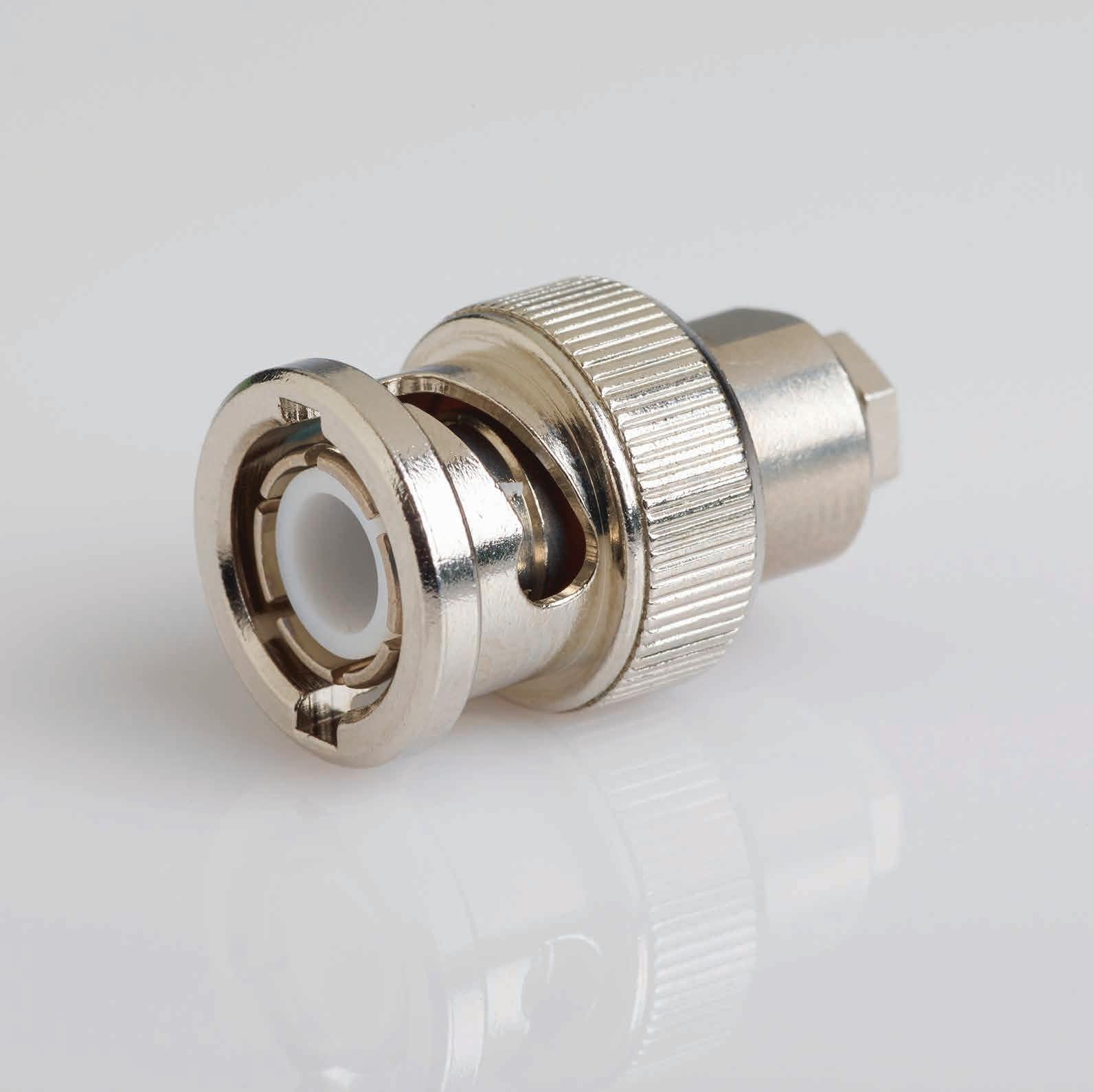
SIMPLIFICATION IS OUR INNOVATON Visit www.radiall.com for more information. SECTION 10 BNC
10-1 Simplification is Our Innovation. Go online for data sheets and assembly instructions. Visit www.radiall.com/AEP and enter the part number.
10-2 SECTION 10 TABLE OF CONTENTS
BNC Cable Connectors
Cable Connectors
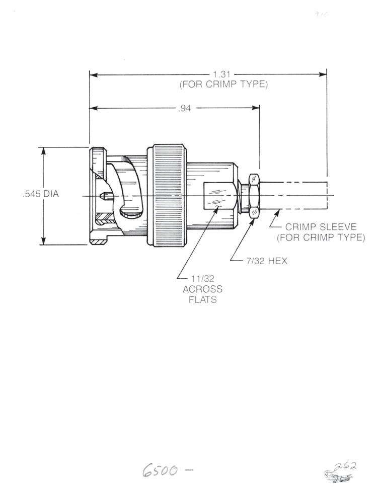
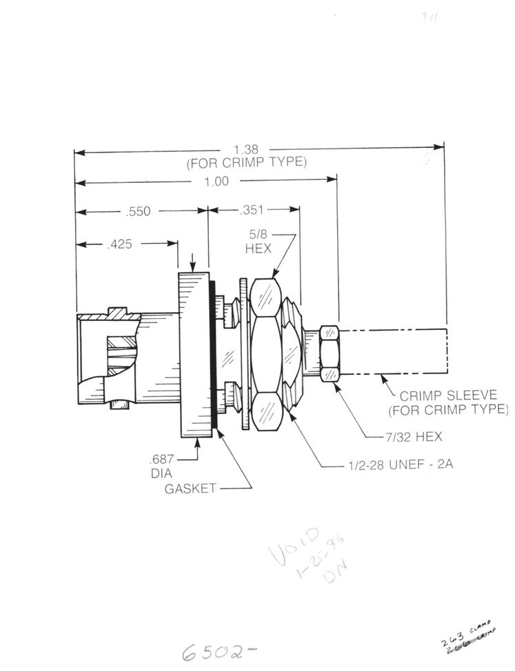
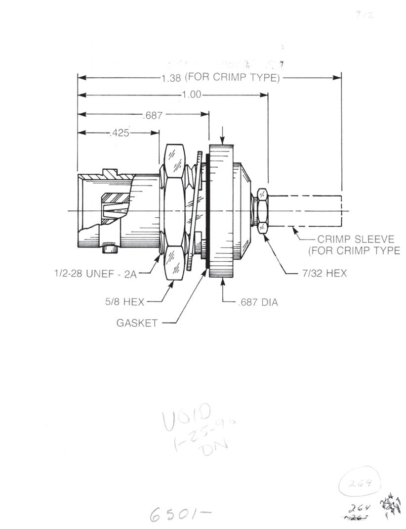
Straight Plug for Flexible or Semi-Rigid Cable
Clamp type for flexible cable: 6500-1051-0XX (Gold-plated)
6500-7051-0XX (Nickel-plated)
Crimp type for flexible cable: 6500-1071-0XX (Gold-plated) 6500-7071-0XX (Nickel-plated)
Solder-clamp for semi-rigid cable: 6500-1041-0XX (Gold-plated)
6500-7041-0XX (Nickel-plated)
Bulkhead Jack • Front mount
Clamp type for flexible cable: 6502-1051-0XX (Gold-plated)
6502-7051-0XX (Nickel-plated)
Crimp type for flexible cable: 6502-1071-0XX (Gold-plated)
6502-7071-0XX (Nickel-plated)
Solder-clamp for semi-rigid cable: 6502-1041-0XX (Gold-plated)
6502-7041-0XX (Nickel-plated)
Bulkhead Jack • Rear mount
Clamp type for flexible cable:
6501-1051-0XX (Gold-plated)
6501-7051-0XX (Nickel-plated)
Crimp type for flexible cable: 6501-1071-0XX (Gold-plated)
6501-7071-0XX (Nickel-plated)
Solder-clamp for semi-rigid cable: 6501-1041-0XX (Gold-plated)
6501-7041-0XX (Nickel-plated)
Substitute XX with the Appropriate Cable Group Below
02 RG178, RG196, M17/93, M17/169 09 0.141˝ semi-rigid, RG402, M17/130
03 RG174, RG179, RG316, M17/113, M17/119, M17/172, M17/173 10 0.085˝ semi-rigid, RG405, M17/133
05 RG178DS, RG196DS 19 RG174DS, RG316DS, M17/152, Times RD316
10-2
Go online for data sheets and assembly instructions. Visit www.radiall.com/AEP and enter the part number.
BNC
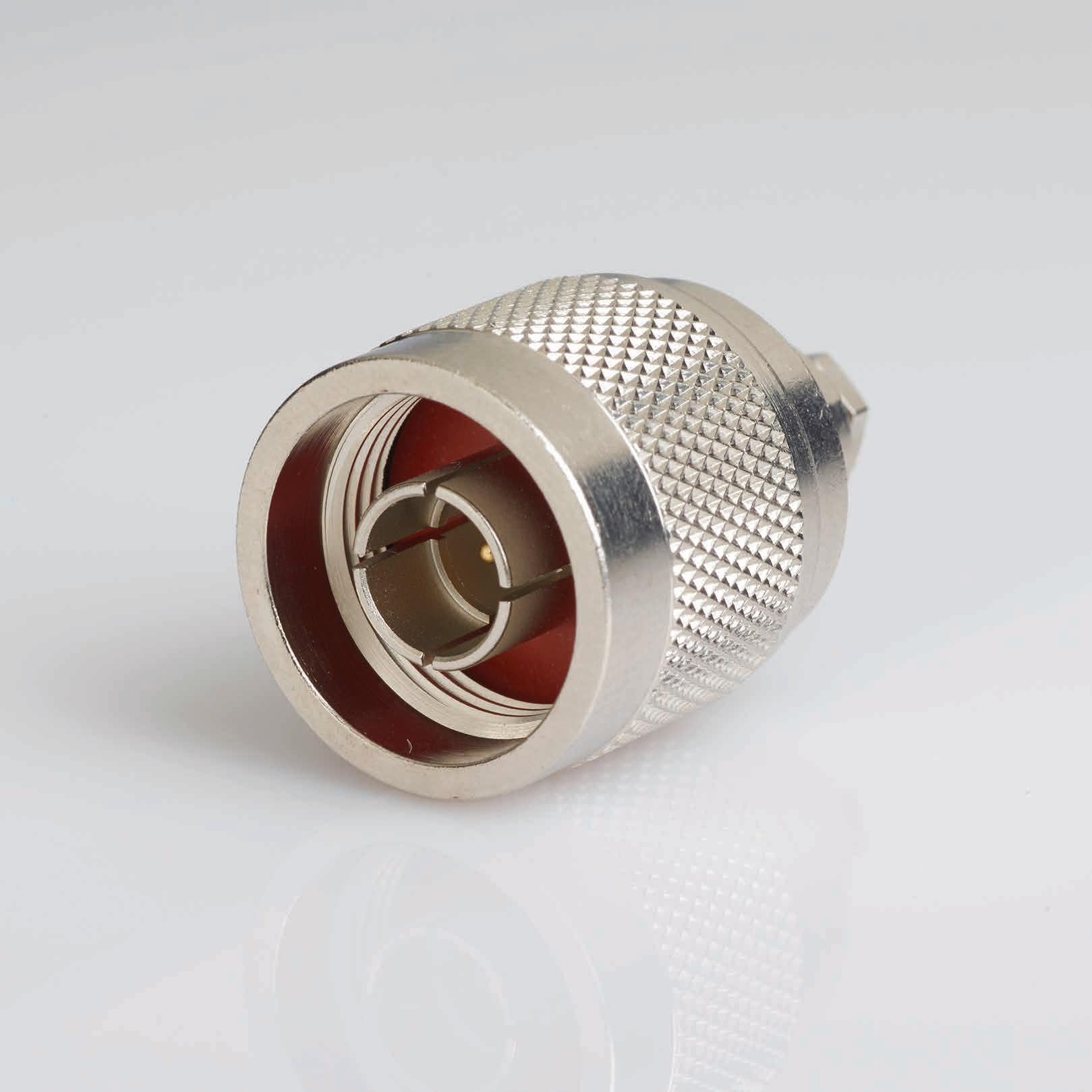
SIMPLIFICATION IS OUR INNOVATON Visit www.radiall.com for more information. SECTION 11
TYPE N
11-1 Simplification is Our Innovation. Go online for data sheets and assembly instructions. Visit www.radiall.com/AEP and enter the part number. Cable Connectors 11-2 Precision Plugs and Jacks……………………………………. 11-3 SECTION 11 TABLE OF CONTENTS
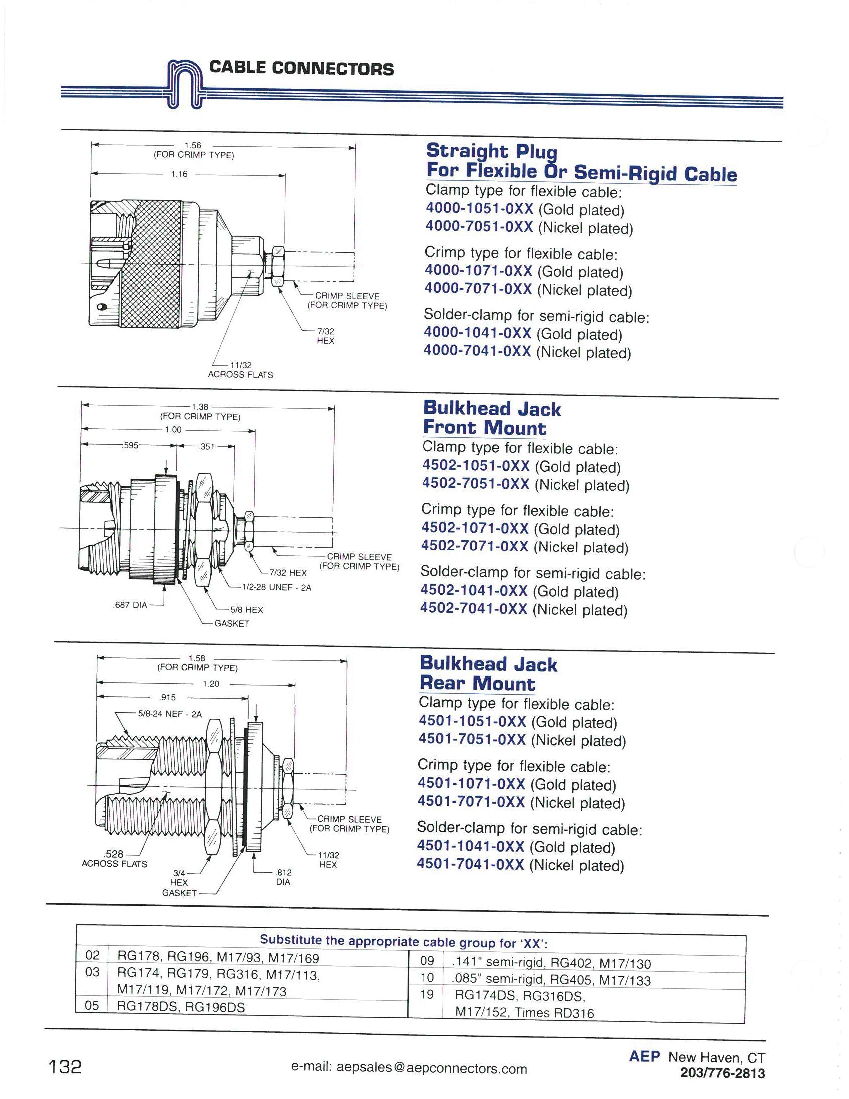
Cable Connectors
Straight Plug for Flexible or Semi-Rigid Cable
Clamp type for flexible cable: 4000-1051-0XX (Gold-plated) 4000-7051-0XX (Nickel-plated)
Crimp type for flexible cable: 4000-1071-0XX (Gold-plated) 4000-7071-0XX (Nickel-plated)
Solder-clamp for semi-rigid cable: 4000-1041-0XX (Gold-plated) 4000-7041-0XX (Nickel-plated)
Bulkhead Jack
• Front mount
Clamp type for flexible cable: 4502-1051-0XX (Gold-plated) 4502-7051-0XX (Nickel-plated)
Crimp type for flexible cable: 4502-1071-0XX (Gold-plated) 4502-7071-0XX (Nickel-plated)
Solder-clamp for semi-rigid cable: 4502-1041-0XX (Gold-plated) 4502-7041-0XX (Nickel-plated)
Bulkhead Jack
• Rear mount
Clamp type for flexible cable: 4501-1051-0XX (Gold-plated) 4501-7051-0XX (Nickel-plated)
Crimp type for flexible cable: 4501-1071-0XX (Gold-plated) 4501-7071-0XX (Nickel-plated)
Solder-clamp for semi-rigid cable: 4501-1041-0XX (Gold-plated) 4501-7041-0XX (Nickel-plated)
Substitute XX with the Appropriate Cable Group Below 02 RG178, RG196, M17/93, M17/169
0.141˝ semi-rigid, RG402, M17/130 03 RG174, RG179, RG316, M17/113, M17/119, M17/172, M17/173
RG196DS
semi-rigid, RG405, M17/133
RG174DS, RG316DS, M17/152, Times RD316
11-2 TYPE N Go online for data sheets and assembly instructions. Visit www.radiall.com/AEP and enter the part number.
09
10
19
0.085˝
05 RG178DS,
Precision Plugs and Jacks
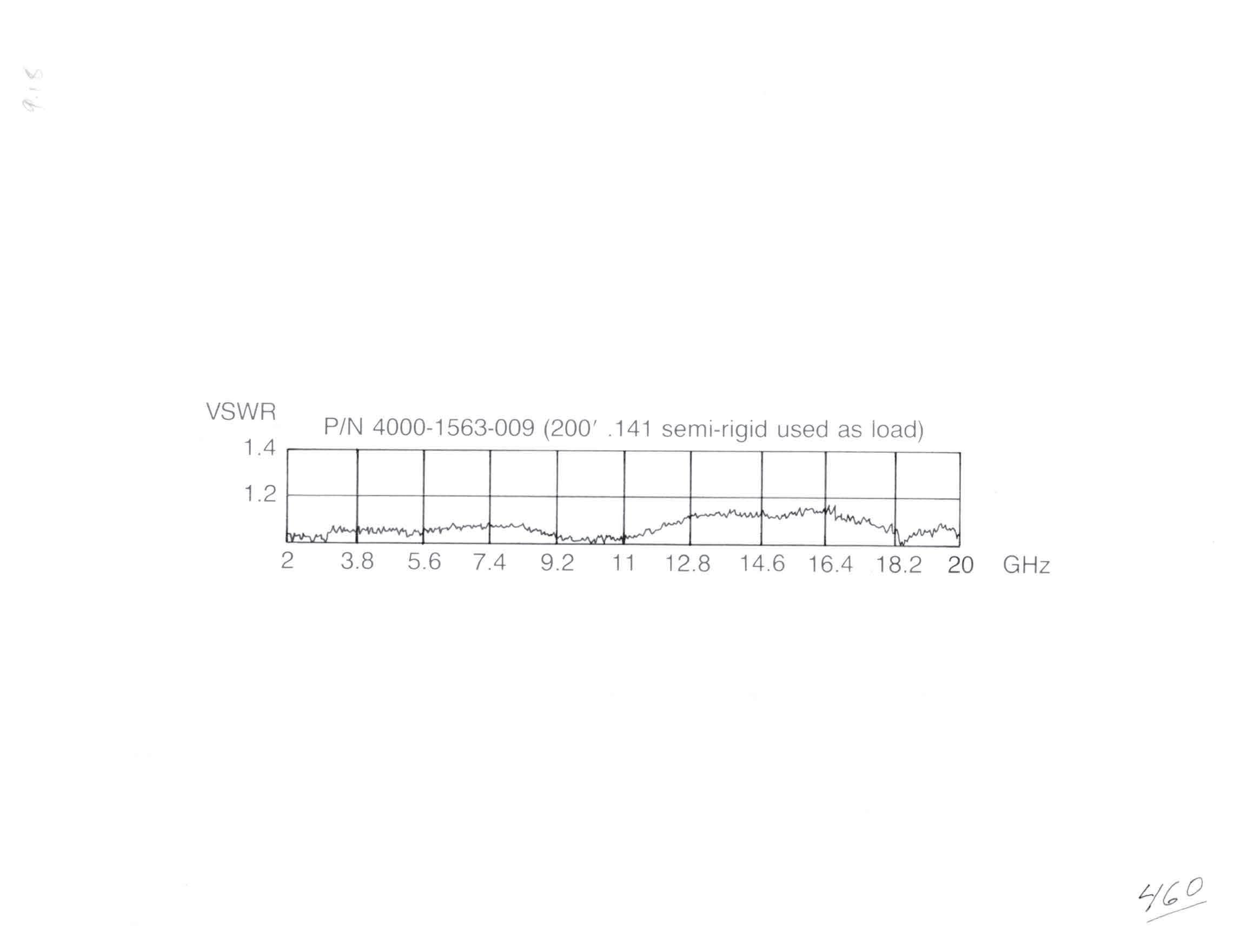
The precision type N connectors shown here are constructed from 303 stainless steel with Teflon insulators and beryllium copper contacts.
These plugs and jacks all have captivated contacts which plug on to the cable center conductor, eliminating contact soldering and gapping. Simply trim the cable, slide the connector on and solder the jacket.
The VSWR data shown is taken from production units.
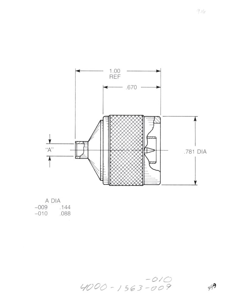
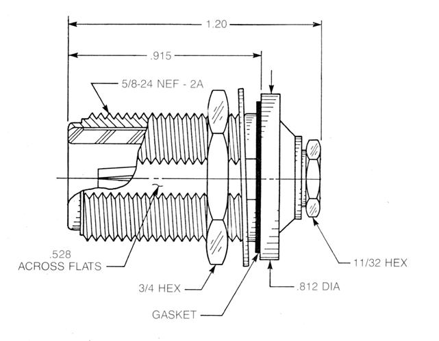
Straight Plug
• Direct solder type
• Gold-plated body, passivated coupling nut
For 0.085˝ semi-rigid (A = 0.089): 4000-1563-010
For 0.141˝ semi-rigid (A = 0.144): 4000-1563-009
Bulkhead Jack
• Solder-clamp type to allow repositioning of D-flats after assembly
• Passivated body, gold-plated solder ferrule
• Rear mount
For 0.085˝ semi-rigid (A = 0.089): 4501-9543-010
For 0.141˝ semi-rigid (A = 0.144): 4501-9543-009
11-3 TYPE N Simplification
Go online for data sheets and assembly instructions. Visit www.radiall.com/AEP and enter the part number.
is Our Innovation.
NOTES
Go online for data sheets and assembly instructions. Visit www.radiall.com/AEP and enter the part number.
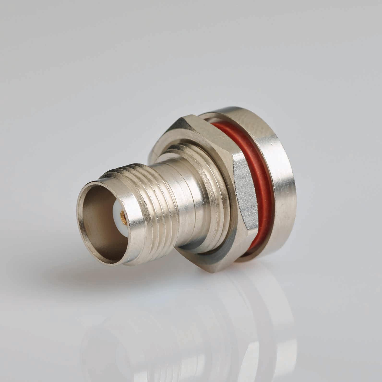
SIMPLIFICATION IS OUR INNOVATON Visit www.radiall.com for more information. SECTION 12 TNC
12-1 Simplification is Our Innovation. Go online for data sheets and assembly instructions. Visit www.radiall.com/AEP and enter the part number. TNC Cable Connectors 12-2 SECTION 12 TABLE OF CONTENTS
Cable Connectors
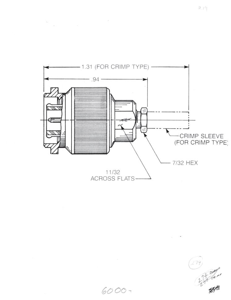
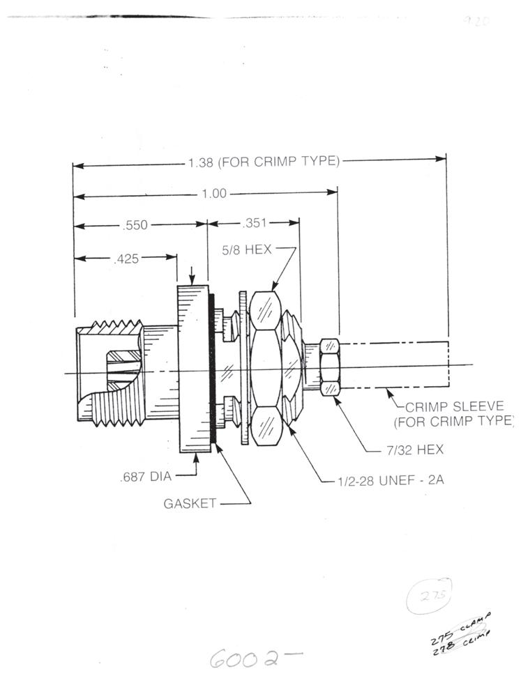
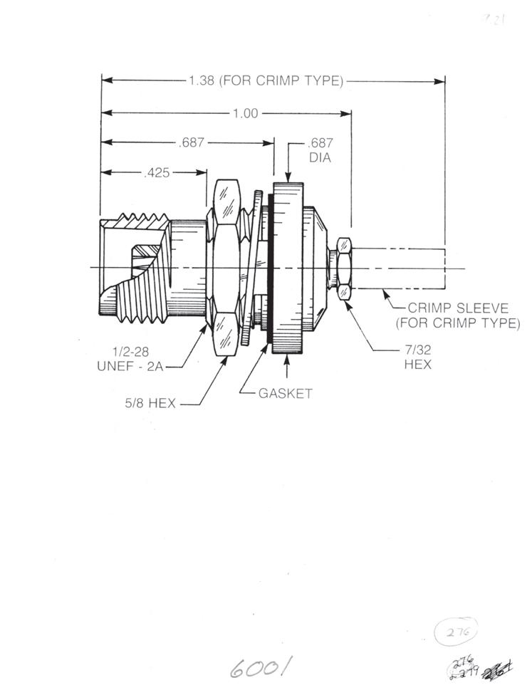
Straight Plug for Flexible or Semi-Rigid Cable
Clamp type for flexible cable: 6000-1051-0XX (Gold-plated) 6000-7051-0XX (Nickel-plated)
Crimp type for flexible cable: 6000-1071-0XX (Gold-plated) 6000-7071-0XX (Nickel-plated)
Solder-clamp for semi-rigid cable: 6000-1041-0XX (Gold-plated) 6000-7041-0XX (Nickel-plated)
Bulkhead Jack
• Front mount
Clamp type for flexible cable: 6002-1051-0XX (Gold-plated) 6002-7051-0XX (Nickel-plated)
Crimp type for flexible cable: 6002-1071-0XX (Gold-plated) 6002-7071-0XX (Nickel-plated)
Solder-clamp for semi-rigid cable: 6002-1041-0XX (Gold-plated) 6002-7041-0XX (Nickel-plated)
Bulkhead Jack
• Rear mount
Clamp type for flexible cable: 6001-1051-0XX (Gold-plated) 6001-7051-0XX (Nickel-plated)
Crimp type for flexible cable: 6001-1071-0XX (Gold-plated) 6001-7071-0XX (Nickel-plated)
Solder-clamp for semi-rigid cable: 6001-1041-0XX (Gold-plated) 6001-7041-0XX (Nickel-plated)
Substitute XX with the Appropriate Cable Group Below
RG178, RG196, M17/93, M17/169
semi-rigid, RG402, M17/130 03 RG174, RG179, RG316, M17/113, M17/119, M17/172, M17/173
semi-rigid, RG405, M17/133
RG316DS, M17/152, Times RD316
12-2
Go online for data sheets and assembly instructions. Visit www.radiall.com/AEP and enter the part number.
TNC
09
10 0.085˝
05
19
02
0.141˝
RG178DS, RG196DS
RG174DS,
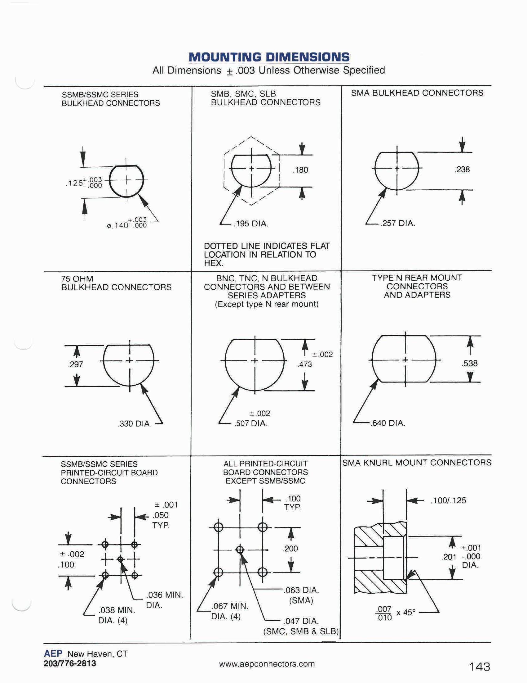
CONNECTOR MOUNTING DIMENSIONS
12-3
Simplification
Innovation.
is Our
NOTES
Go online for data sheets and assembly instructions. Visit www.radiall.com/AEP and enter the part number.

CABLE ASSEMBLIES
SIMPLIFICATION IS OUR INNOVATON Visit www.radiall.com for more information. SECTION 13
13-1 Simplification is Our Innovation. Go online for data sheets and assembly instructions. Visit www.radiall.com/AEP and enter the part number. Design Considerations 13-3 Cable Data 13-5 Cable Groups 13-6 Trim Codes 13-7 Short Bend Assemblies 13-8 Standard Flexible Assemblies 13-9 Standard Semi-Rigid Assemblies 13-12 Assembly Instructions.......... 13-14 SECTION 13 TABLE OF CONTENTS
CABLE ASSEMBLIES
Even the best coaxial connector won't work right unless it is correctly assembled to the cable. Since we make the connectors, we have the knowledge and the ability to do the job right.
If you make your own cable assemblies, here's what you have to do:
• Determine what you’ll need to do the job, accounting for scrap rates.
• Buy and stock connectors, cable, markers and shrink tubing.
• Develop a training system for your assemblers.
• Develop and maintain the assembly tooling and test equipment.
• Scrap parts damaged during assembly as well as complete assemblies that don't meet specifications.
• Juggle your production schedule to make sure the right assemblies are ready for installation at the right time.
If you buy complete assemblies from us, here's what you have to do:
• Install the assemblies in your equipment.
The following pages show a number of suggestions for minimizing your cost of cable assemblies. Send us your drawings and we'll show you how to get the assemblies you need, when you need them, without frustration.
13-2
Go online for data sheets and assembly instructions. Visit www.radiall.com/AEP and enter the part number.
Cable Assembly Guidelines
DESIGN CONSIDERATIONS FOR FLEXIBLE ASSEMBLIES
There are a number of things that, when kept in mind while specifying flexible cable assemblies, can cut costs and ensure the best possible performance:
1) Crimp type connectors are faster and less expensive to assemble than clamp types and provide better strain relief at the cable junction. Crimp connectors grip five to ten times more length of braid than clamp connectors do, an important consideration given the small cross-sectional area of most coaxial cable braid wires.
2) Nickel-plated or passivated connectors provide the same electrical performance as gold-plated connectors but at a lower price.
3) Cable terminations (see pages 7-1 to 7-4) can often eliminate the need for (and expense of) a cable connector/receptacle combination in applications where one end of the cable will not need to be disconnected during service.
4) Cables with wrapped-tape dielectrics and/or jackets are generally more expensive to buy and always more expensive to assemble than cables with extruded dielectrics and jackets.
5) Soldering the braid of flexible cables to connectors should ALWAYS be avoided. The heat used in soldering will damage even cables with Teflon dielectrics, and will destroy cables with polyethylene dielectrics. All AEP connectors grip the cable with strength greater than the breaking strength of the cable braid, so soldering is also redundant.
6) Excessively tight tolerances will increase cost. Additionally, if enough slack is not designed into the specification, you may run the risk of having cables that will be under constant mechanical stress when installed, thereby degrading the electrical performance over time.
7) All screw-on connectors have some play in the coupling nuts, so lengths should be dimensioned to the reference plane. In general, length should be dimensioned to the following points:
• Straight plugs and jacks: To reference plane.
• Bulkhead jacks: To bulkhead mounting surface.
• Right angle connectors: To centerline of mating side.
The standard flexible cable assemblies shown on the following pages all have nickel-plated crimp type connectors, and have heat-shrink tubing installed at the cable junction.
DESIGN CONSIDERATIONS FOR SEMI-RIGID ASSEMBLIES
Since semi-rigid assemblies are generally used at higher frequencies than flexible assemblies, the design and construction elements are more critical. We make our own bending and trimming equipment, and use induction heating only (not resistance pliers) for soldering cable jackets. We can make semi-rigid assemblies using any connectors on cable sizes from 0.047˝ to 0.250˝, made and tested to meet your specifications, 100% guaranteed.
Keeping the following in mind can cut cost and ensure the best possible performance in semi-rigid assemblies:
CABLE ASSEMBLIES
13-3
Simplification
Go online for data sheets and assembly instructions. Visit www.radiall.com/AEP and enter the part number.
is Our Innovation.
CABLE ASSEMBLIES
Cable Assembly Guidelines (continued)
1) When using 0.141˝ semi-rigid cable and SMA connectors, the best performance is gained from using plugs that use the cable center conductor as the contact, such as our 9301-1063-009. One problem presented by this connector used to be that the sharp edge of the pointed center conductor would shed metal chips onto the interface each time the connector was mated. Since we use only the best equipment available to manufacture our cable assemblies, we are able to produce a point which virtually eliminates this problem. Our equipment also enables us to machine an extremely smooth, burr-free finish on the interface, which is critical for high-frequency applications.
2) Dimensions should be as tight as possible and tolerances as loose as possible. Tolerances less than ± 0.030" add extra expense.
3) Extremely tight bends are expensive and will cause the cable center conductor to migrate toward the outside of the bend over time. Bend radii should be as large as possible and never smaller than 1.5 times the cable diameter (measured to the inside of the cable). A minimum of two cable diameters of straight length should be allowed from the connector attachment before starting bends.
4) Lengths should be dimensioned to the following points, since they are a fixed characteristic of the connectors and installation locations:
• Straight plugs and jacks: To reference plane.
• Bulkhead jacks: To bulkhead mounting surface.
• Right angle connectors: To centerline of mating end.
5) We can bend cables tightly enough, without damage, that a straight SMA plug with a 90° bend will fit in the same space as a right angle plug. Right angle plugs are more expensive and have relatively poor electrical performance at high frequency.
6) The drawing below illustrates a dimensioning method that is easiest to translate into finished assemblies.
a) Straight lengths should be dimensioned to the start of bends.
b) Bends should be specified by radius to the inside of cable and degrees of bend. Radii to center of cable are unmeasurable.
c) Dimensions that cannot be definitively measured, such as intersections of centerlines of bent cables as shown below, should be avoided.
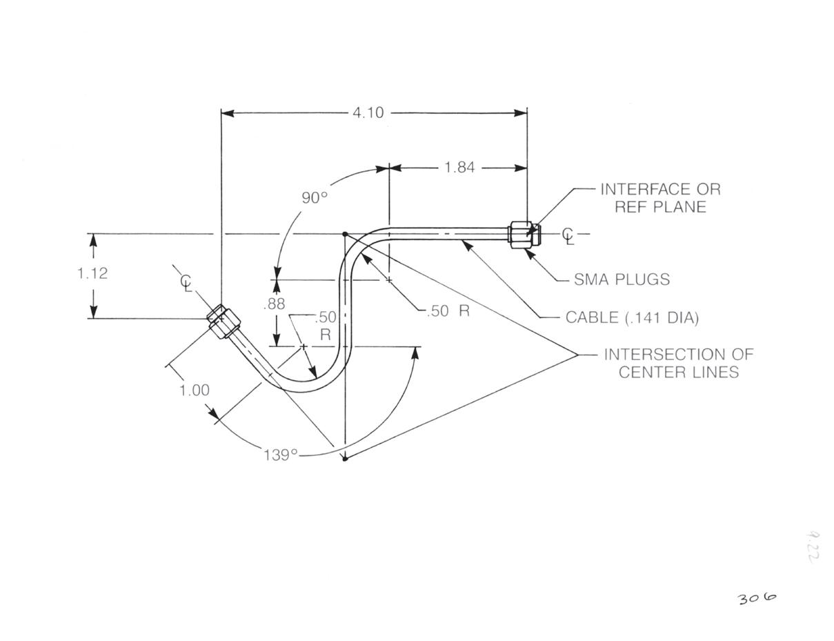
The standard semi-rigid assemblies shown on the following pages all use nickel-plated connectors and hand-formable (soft jacketed) semi-rigid cable.
13-4
Go online for data sheets and assembly instructions. Visit www.radiall.com/AEP and enter the part number.
FLEXIBLE CABLE
SEMI-RIGID CABLE
CENTER CONDUCTOR
DIELECTRIC
BRAID
JACKET
CENTER CONDUCTOR
DIELECTRIC
OUTER CONDUCTOR
KEY TO MATERIAL CODES:
A. Silver-covered copper
B. Silver-covered copperweld
C. Copperweld
D. Double braid
E. Tinned copper
F. Bare copper
G. Polyethylene
H. PTFE (Teflon)
I. Fiberglass
J. PVC
K. FEP (Teflon)
S. Stranded center conductor
Data is compiled from MIL-C-17 and manufacturer 's literature and is not a guarantee of performance.
13-5
Simplification is Our Innovation. Go online for data sheets and assembly instructions. Visit www.radiall.com/AEP and enter the part number. 55 26, 167 01 A 0.032 G 0.116 DE 0.176 G 0.206 50 USE RG- 223 58 28, 155, 197 06 SE 0.036 G 0.116 E 0.150 J 0.195 50 1.0 28 55 59 29 07 C 0.023 G 0.146 F 0.191 J 0.242 75 1.0 16 72 62 30, 91, 97 07 C 0.025 G 0.146 F 0.191 J 0.242 93 1.0 13 45 122 54, 197, 197 30 SE 0.031 G 0.096 E 0.126 J 0.160 50 1.0 30 35 141 59, 170 06 B 0.039 H 0.116 A 0.146 I 0.190 50 USE RG- 303 142 60, 158 01 B 0.037 H 0.116 DA 0.171 K 0.195 50 12.4 76 140 174 119, 173 03 SC 0.019 H 0.060 E 0.088 J 0.110 50 1.0 45 17 178 93, 169 02 SB 0.012 H 0.033 A 0.054 K 0.071 50 3.0 94 47 179 94 03 SB 0.012 H 0.063 A 0.084 K 0.100 75 3.0 43 150 180 95 04 SB 0.012 H 0.102 A 0.124 K 0.141 95 3.0 36 150 187 68, 94 03 SB 0.012 H 0.063 A 0.084 K 0.100 75 USE RG- 179 188 69, 113 03 SB 0.020 H 0.060 A 0.081 K 0.110 50 USE RG- 316 195 70, 95 04 SB 0.012 H 0.102 A 0.124 K 0.155 95 USE RG- 180 196 71, 169 02 SB 0.012 H 0.034 A 0.054 K 0.080 50 USE RG- 178 223 84, 167, 200 01 A 0.035 G 0.116 DA 0.176 J 0.212 50 12.4 100 11 303 111, 170 06 B 0.037 H 0.116 A 0.146 K 0.170 50 3.0 26 350 316 1136, 172 03 SB 0.020 H 0.060 A 0.081 K 0.098 50 3.0 58 78 400 128, 175 01 SA 0.038 H 0.116 DA 0.171 K 0.095 50 12.4 90 140 - 152 19 SB 0.020 H 0.060 DA 0.096 K 0.114 50 12.4 85 37 TIMES RD-178 25 SB 0.012 H 0.034 DA 0.070 K 0.092 50 3.0 94 47 TIMES RD-316 19 SB 0.020 H 0.060 DA 0.096 K 0.118 50 3.0 58 78 402 130 09 B .036 H .118 F .141 50 12 45 64 405 133 10 B .020 H .066 F .086 50 22 80 123 - 151 11 B .011 H .037 F .047 50 40 130 180 0.056˝ SEMI-RIGID 21 B .011 H .037 F .056 50 35 117 161
CABLE DATA
RGRGM17 M17
GROUP AEP CABLE GROUP (POWER (W) AT MAX 18 GHz 10 GHz ATTENUATION (dB/100 FT) AT MAX MAX FREQUENCY (GHZ) ATTENUATION (DB/100 FT) IMPEDANCE IMPEDANCE
AEP CABLE
AEP CABLE GROUPS
Each cable group includes all modification letters for RG numbers shown and all dash numbers for M17 slash sheets shown. For specific information on cables, please consult MIL-C-17 or the cable manufacturers.
01
All series except SSMB/SSMC. Crimp only for SMB, SMC, BNC, TNC, N, terminations. 0.213 02 RG-178, 196, M17/93, M17/169
RG-55, 142, 223, M17/60, M17/84, M17/158, M17/167
RG-174, 179, 187, 188, 316, M17/94, 113, 119, 172, 173 All
RG-180, 195, M17/95, Essex 21-597, Raychem 9527-A-1317, 9528-A-1317
All series except SSMB/SSMC. Crimp only for SMB, SMC, BNC, N, TNC, terminations. 0.156 05 RG 178DS, 196DS, Microdot 250-3908
06
RG-58, 141, 303, M17/111, M17/28, M17/155, M17/170
M17/29, M17/30
0.141˝ semi-rigid, RG-402, M17/130
M17/133
All series except SSMB/SSMC. Crimp only for SMB, SMC, BNC, N, TNC, terminations. 0.213
Raychem 9530-A-1317, Microdot 295-3986
RG-174DS,316DS, M17/152, Times RD316
(0.156 for SMA)
RG-122, M17/54, M17/157 SMA QPL
The references above indicate only standard cable/connector combinations. Please contact us directly if you need something you don't see.
13-6
Go online for data sheets and assembly instructions. Visit www.radiall.com/AEP and enter the part number. Group Cable(s) Standard Application Die Size for Crimp
0.105
All series
03
0.128 04
series
0.128
SSMB/SSMC)
All series
(0.105 for
75
0.255 09
All
All
14
All series 0.128
-
0.128
SSMB/SSMC
N/A 25
All series 0.128
-
07 RG-59, 62,
Ohm
series except SSMB/SSMC N/A 10 0.085˝ semi-rigid, RG-405,
series N/A 11 0.045˝/0.047˝ semi-rigid SSMB/SSMC series N/A 13
Contact factory
Microdot 250-4021
15 Microdot 250-3953 Contact factory
19
All series except SMA
21 0.056˝ semi-rigid
series
Times RD178
30
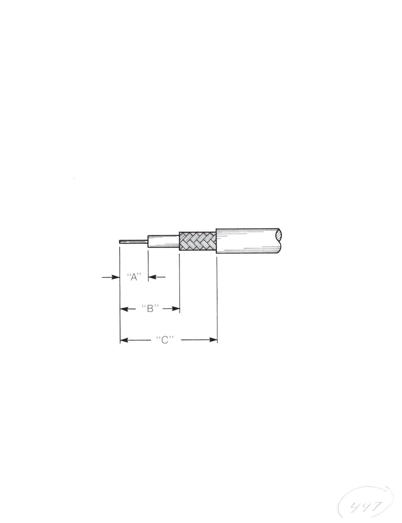
* Break edge if no angle for “G” given.
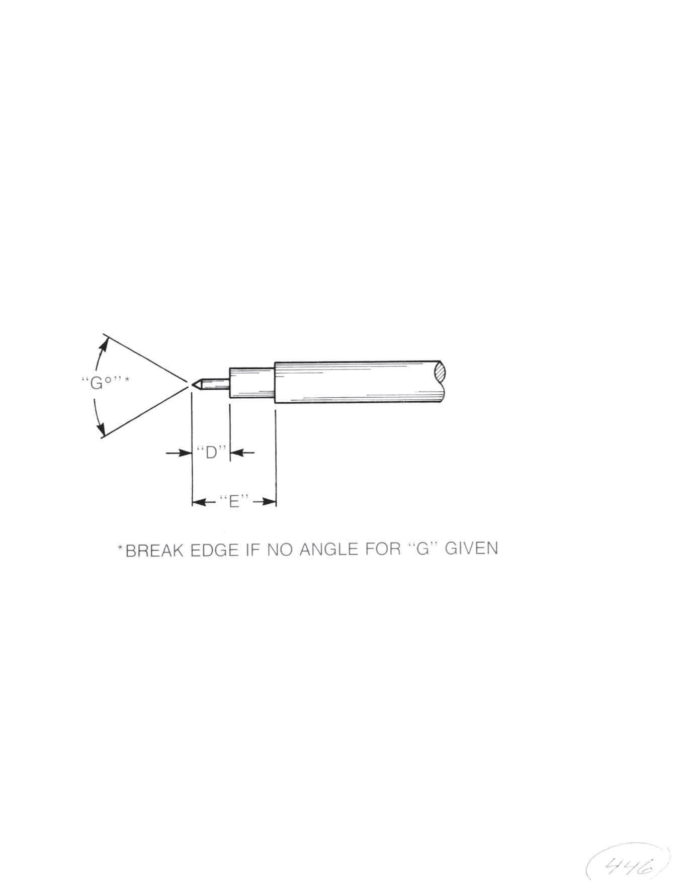
TRIM CODES
13-7
Go online for data sheets and assembly instructions. Visit www.radiall.com/AEP and enter the part number.
TRIM CODE # DIM “A” DIM “ B” DIM “C” TRIM CODE # DIM “ D ” DIM “ E” DIM “G” 1 0.080 0.120 0.240 101 0.090 0.0902 0.100 0.430 0.700 102 0.090 0.180 70° - 90° 3 0.080 0.180 0.300 103 0.100 0.1354 0.070 0.200 0.450 104 0.080 0.1705 0.100 0.125 0.265 105 0.125 0.1256 0.100 0.475 0.725 106 0.125 0.2907 0.075 0.200 0.350 107 0.090 0.090 70° - 90° 8 0.075 0.250 0.500 108 0.100 0.2159 0.125 0.300 0.400 109 0.060 0.12010 0.100 0.230 0.500 110 0.115 0.33011 0.125 0.600 0.850 111 0.125 0.33012 0.100 0.600 0.870 112 0.090 0.17013 0.125 0.325 0.425 113 0.105 0.13014 0.100 0.160 0.390 114 0.120 0.15015 0.100 0.470 0.720 115 0.200 0.35016 0.100 0.100 0.230 116 0.100 0.18017 0.100 0.210 0.430 117 0.125 0.19518 0.100 0.275 0.400 118 0.075 0.10019 0.125 0.125 0.275 119 0.110 0.14020 0.125 0.515 0.765 120 0.110 0.15021 0.200 0.220 0.310 121 0.125 0.125 70° - 90° 22 0.200 0.510 0.760 122 0.090 0.090 70° - 90° 23 0.125 0.300 0.490 123 0.125 0.195 70° - 90° 24 0.125 0.300 0.490 124 0.000 0.125 70° - 90° 25 0.050 0.100 0.250 125 0.075 0.07526 0.070 0.265 0.515 27 0.080 0.180 0.425 28 0.150 0.300 0.400 29 0.150 0.600 0.850 30 0.100 0.280 0.550
CABLE ASSEMBLIES
Short Bend Cable Assemblies
AEP SHORT BEND ASSEMBLIES
Designed for test labs and production environments, Radiall AEP introduces the line of Short Bend cable assemblies. Short bend is a perfect solution when a low-loss coaxial cable assembly is needed for point-to-point applications that require low profile bending.
Radiall AEP Short Bend is a 26 GHz, low-loss coaxial cable assembly specifically designed for point-to-point applications that require low profile bending. Short Bend is an alternative to semi rigid and/or hand conformable cables and eliminates the need for special cable bending tools.
Short Bend provides a flexible solution in tight spaces and can possibly eliminate the need for right angle connectors.
ELECTRICAL:
Impedance: 50 Ω
Frequency range: DC-26 GHz
VSWR: 1.02+0.01×f (GHz)
Intermodulation: typ. -123 dBM (-166 dBc, 2 carriers 2X20 W + 43 dBM) 2×20 W+43 dBM
ENVIRONMENTAL:
Operating temperature: -55°C/+125°C
Moisture: IP67
MECHANICAL:
Coupling nut retention force: ≥450 N
Coupling torque: Ncm min
Recommended torque: 10 Nm for tool screw version
Mating life: 100 cycles min
Straight Plug to Straight Plug
0.086˝ CABLE: 81-6200-XXXX
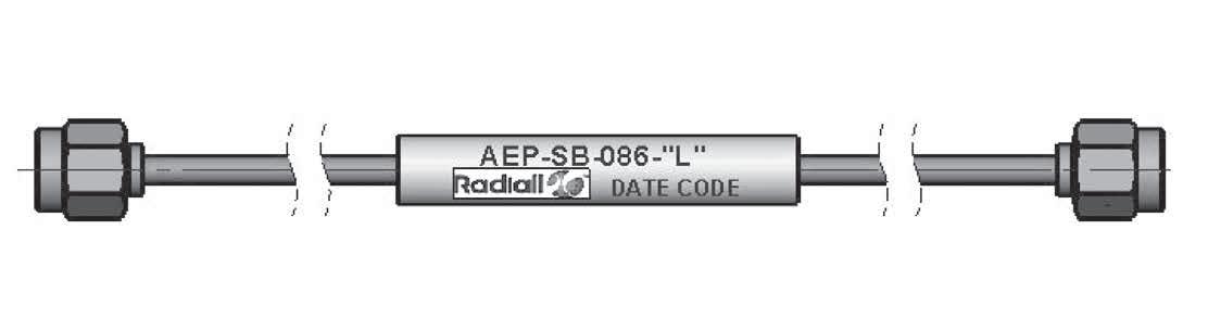
Straight Plug to Straight Plug
0.141˝ CABLE: 81-6201-XXXX
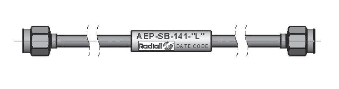
(-XXXX refers to length of assembly (example 81-6200-0600 is 6˝ long) Standard lengths available from 2.5˝ up to 16˝; Custom lengths available upon request.
13-8
Go online for data sheets and assembly instructions. Visit www.radiall.com/AEP and enter the part number.
Simplification is Our Innovation.
Flexible Assemblies - SMA Series Connectors
9001-9023-0XX
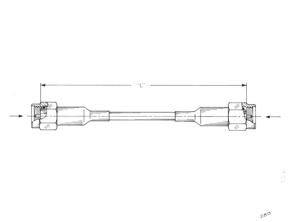
9043-9523-0XX
9001-9023-0XX
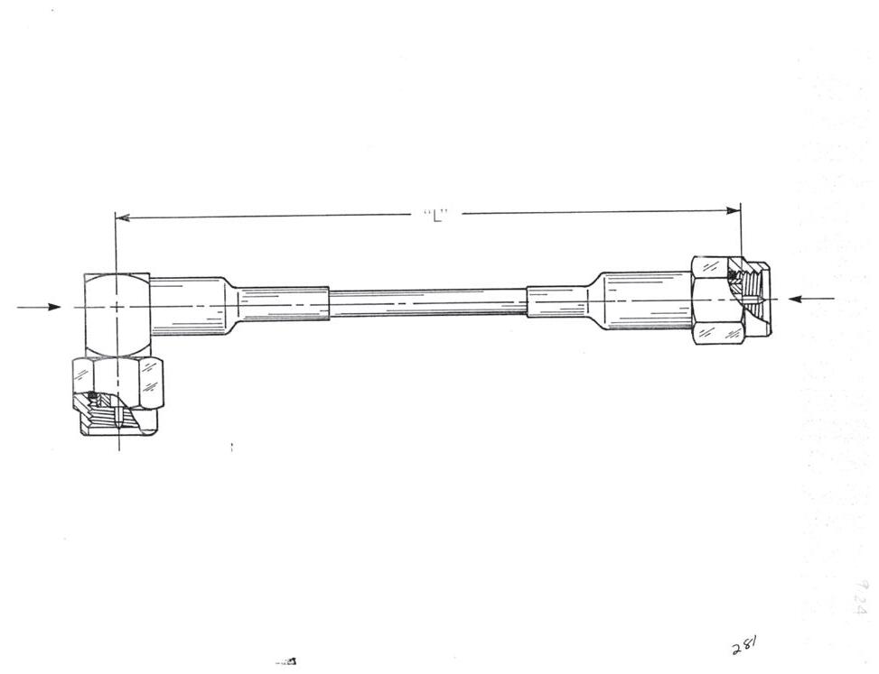
9001-9023-0XX
9043-9523-0XX
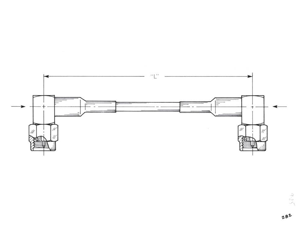
9001-9023-0XX
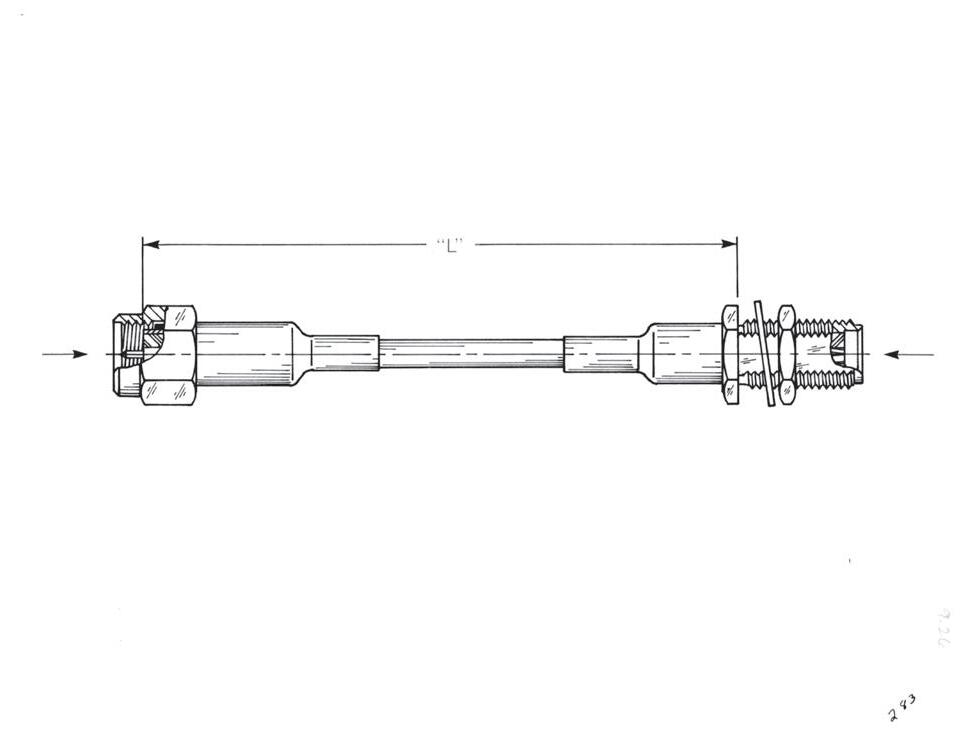
9043-9523-0XX
CABLE ASSEMBLIES
9043-9523-0XX
9030-9023-0XX
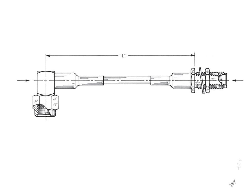
9030-9023-0XX
The last four digits represent length “L” in inch and decimal fractions. Example: 80-1154-1200 indicates one ft O.A.L. Tolerance: ± ¹/8
13-9
Go online for data sheets and assembly instructions. Visit www.radiall.com/AEP and enter the part number.
CABLE ASSEMBLIES
Flexible Assemblies - SMB Series Connectors
2002-7571-003
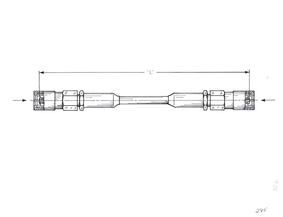
2105-7521-003
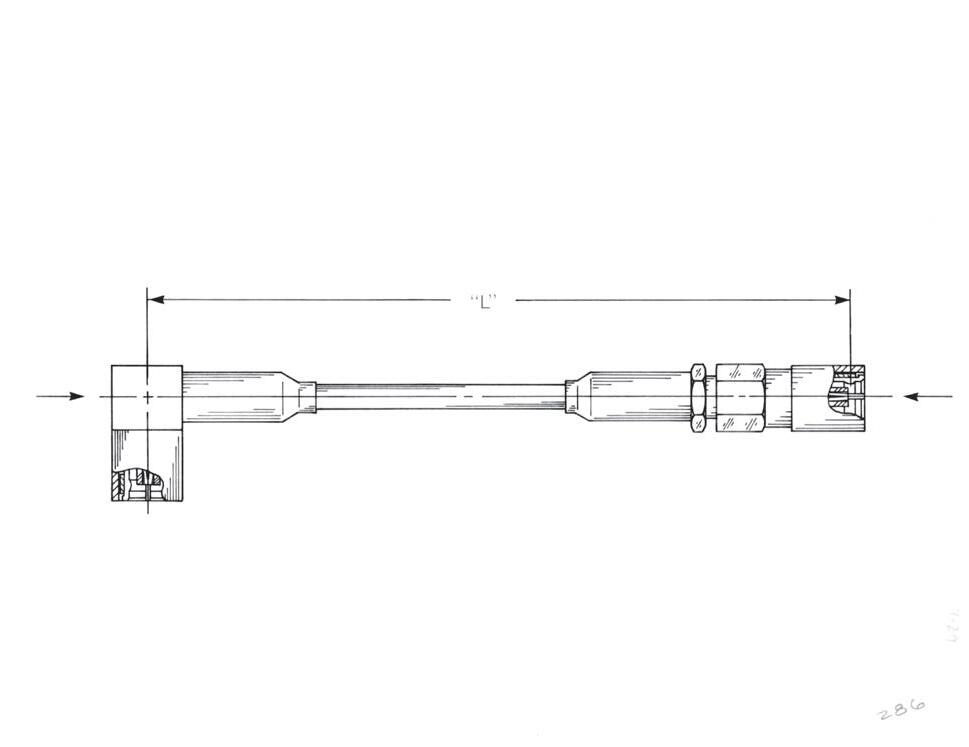
2002-7571-003
2002-7571-003
2105-7521-003
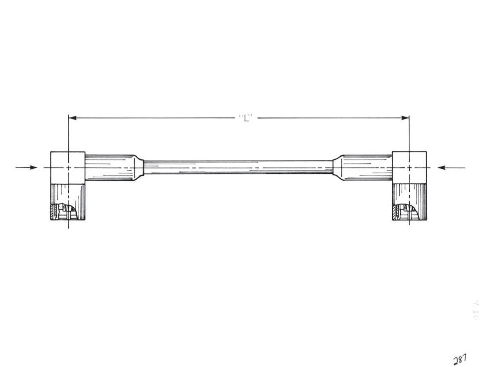
2105-7521-003
2002-7571-003
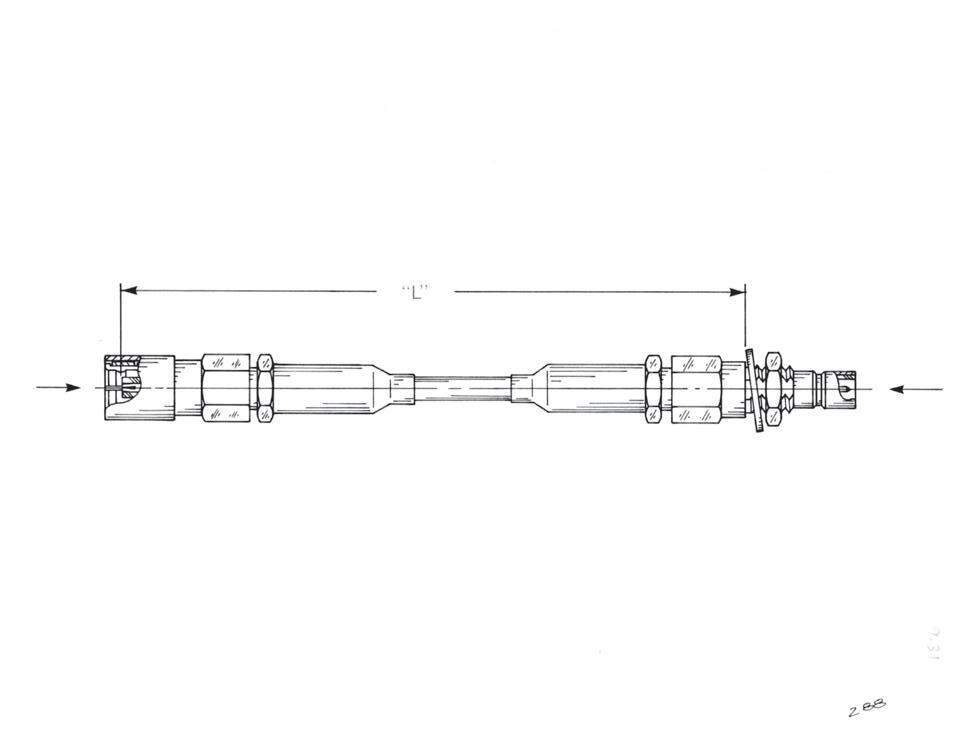
2105-7521-003
2003-7571-003
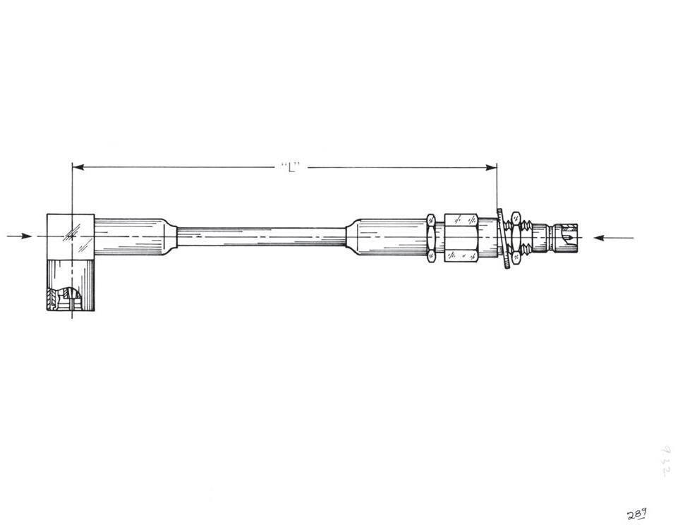
2003-7571-003
The last four digits represent length “L” in inch and decimal fractions. Example: 80-1154-1200 indicates one ft O.A.L. Tolerance: ± ¹/8
13-10
Go online for data sheets and assembly instructions. Visit www.radiall.com/AEP and enter the part number.
Simplification is Our Innovation.
Flexible - SMC Series Connectors
1002-7571-003

1105-7521-003
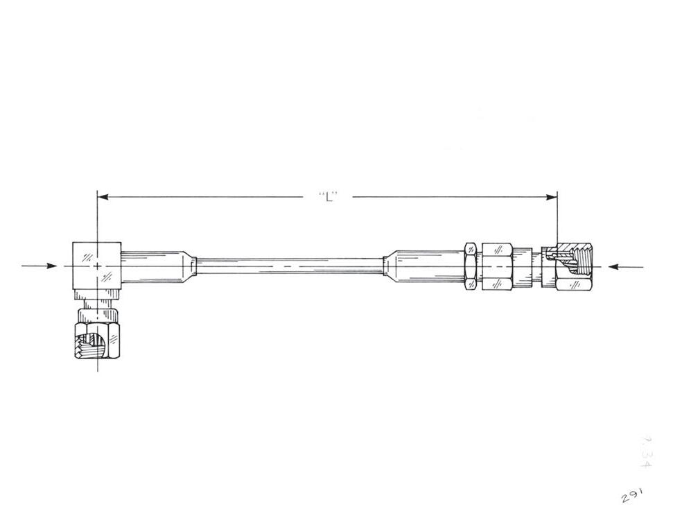
1002-7571-003
1105-7521-003
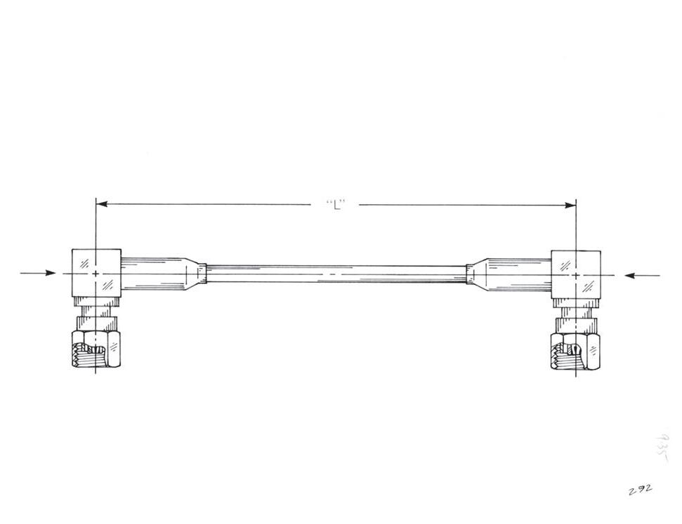
1002-7571-003
CABLE ASSEMBLIES
1105-7521-003
1002-7571-003
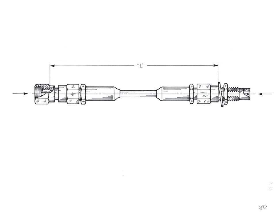
1105-7521-003
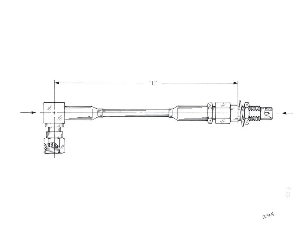
1003-7571-003
1003-7571-003
The last four digits represent length “L” in inch and decimal fractions. Example: 1157-1425-1200 indicates 14 ¼˝ O.A.L. Tolerance: ± ¹/8
13-11
Go online for data sheets and assembly instructions. Visit www.radiall.com/AEP and enter the part number.
CABLE ASSEMBLIES
Semi-Rigid Cable Assemblies - SMA Series Connectors
Straight Plug to Straight Plug
0.085˝ SEMI-RIGID: 81-1224-XXXX
0.085˝: 9401-7083-010
0.141˝: 9301-7063-009
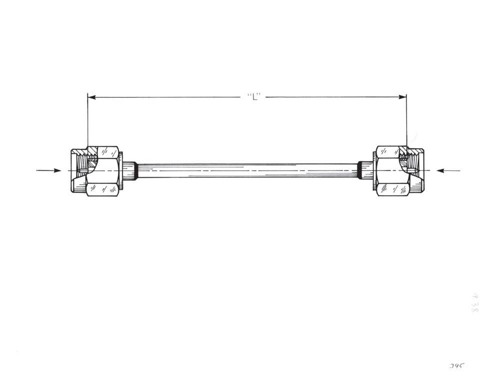
0.085˝: 9401-7083-010
0.141˝: 9301-7063-009
0.085˝: 9401-7083-010
0.141˝: 9301-7063-009
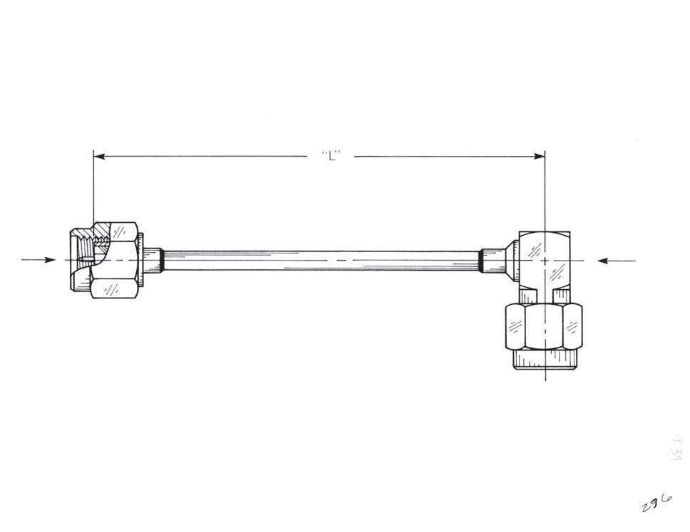
Right Angle Plug to Right Angle Plug
0.085˝ SEMI-RIGID: 81-1227-XXXX
9443-7563-0XX
9443-7563-0XX
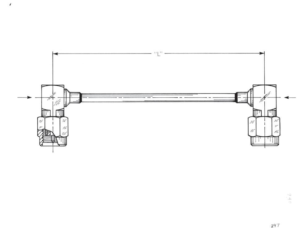
9443-7563-0XX
The last four digits represent length “L” in inch and decimal fractions. Example: 81-1225-1850 indicates 18 ½˝ O.A.L. Tolerance: ± ¹/8 ˝
13-12
Go online for data sheets and assembly instructions. Visit www.radiall.com/AEP and enter the part number.
Semi-Rigid Cable Assemblies - SMA Series Connectors
Straight Plug to Bulkhead Jack
0.085˝: 9401-7083-010
0.141˝: 9301-7063-009
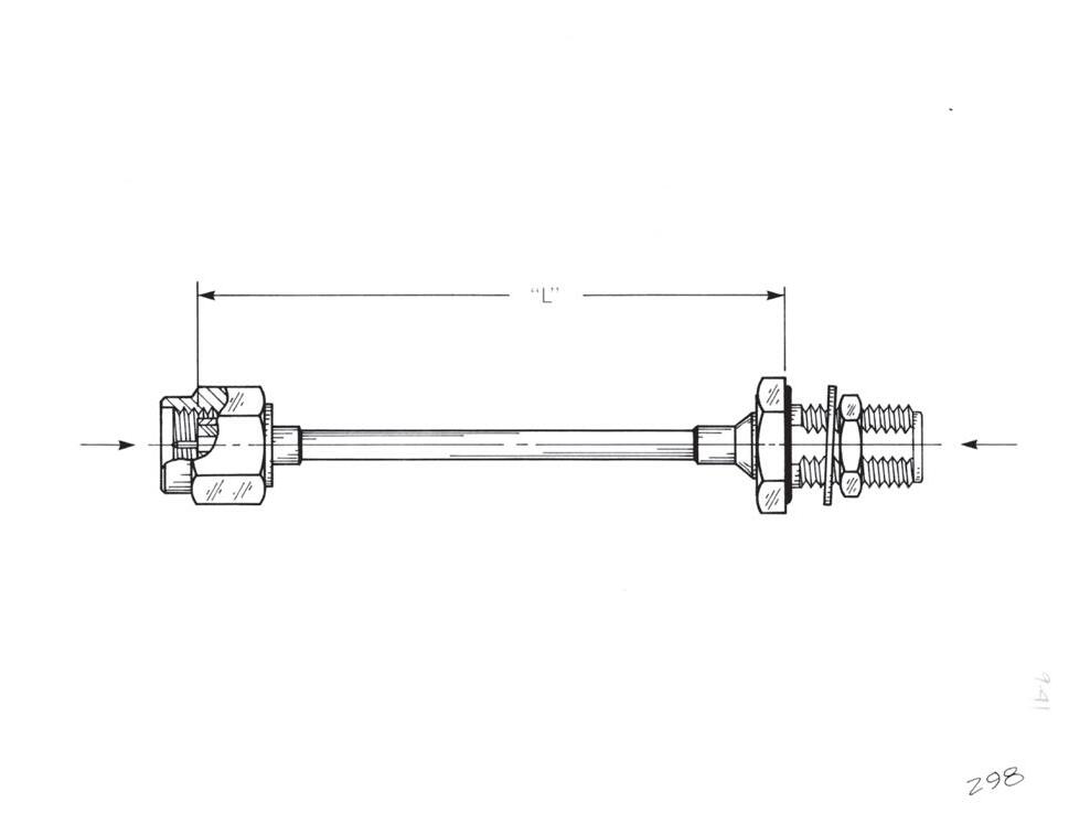
Right Angle Plug to Bulkhead Jack
9443-7563-0XX
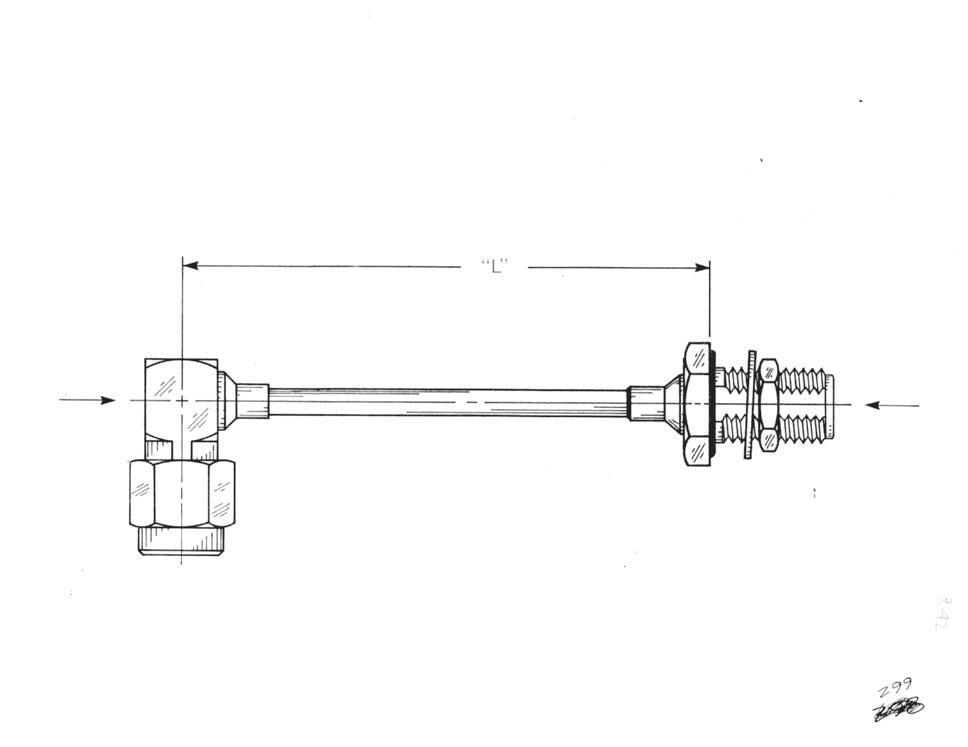
Panel Jack to Panel Jack 2-Hole Flange
0.085˝ SEMI-RIGID:
Simplification is Our Innovation.
9453-7083-0XX
CABLE ASSEMBLIES
9453-7083-0XX
9441-7083-0XX
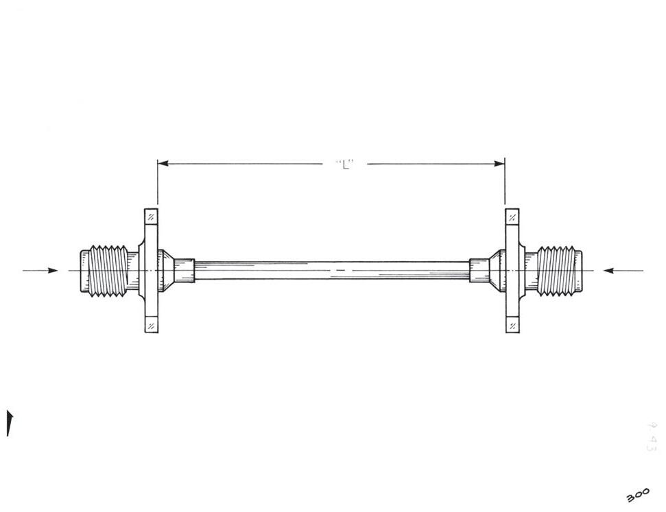
9441-7083-0XX
The last four digits represent length “L” in inch and decimal fractions. Example: 81-1233-0925 indicates 9 ½˝ O.A.L. Tolerance: ± ¹/8
13-13
Go online for data sheets and assembly instructions. Visit www.radiall.com/AEP and enter the part number.
CABLE ASSEMBLIES
Cable Assembly Instructions
General Notes:
1) All cuts when trimming cable should be square and of precise depth. Nicking the layer underneath the layer being cut will weaken the cable mechanically and adversely affect electrical performance.
2) The hole in the side of the cable entry hole in contacts is there for two reasons: A) To visually inspect for proper cable insertion, and B) to allow gases formed during the soldering process to escape. It is NOT for feeding solder into the contact. Even the steadiest operator will end up with a glob of solder on the outside of the contact when using the inspection hole to feed solder. This solder on the outside of the contact makes the connector hard or impossible to assemble, and degrades electrical performance. Filing the solder glob off the contact removes plating. The proper procedure is to tin the cable center conductor, and add some liquid flux to the tinned end just before soldering to the contact. Simply insert the tinned and fluxed cable into the contact and reheat until the solder has melted.
3) Always avoid excessive heat when soldering. Carbon-jawed resistance pliers are much more precise and faster than soldering irons.
4) Always heat the sleeve, body, or contact, not the cable component being soldered.
5) When soldering nickel-plated connector bodies to semi-rigid cable, use Kester #2331 flux. This flux is active enough to ensure good solder bonding and is water-soluble.
6) When soldering to the jacket of semi-rigid cable, the cable and solder ferrule or connector body should be fixtured as tightly as possible. The soldering operation should be carried out as rapidly as possible and the joint cooled by brushing with alcohol. This, combined with a thermal cycling of the bent cable before assembly, will minimize Teflon extrusion during soldering. All major semi-rigid cable manufacturers outline cable thermal cycling procedures in their literature.
7) When cable sub-assemblies are threaded into bodies, always turn the nut, not the body, to prevent twisting the cable and breaking the center conductor.
8) After trimming cable for use with crimp connectors, rotate the dielectric several times to flare the cable braid slightly. This step prevents braid wires from sliding inside the crimp tail during assembly.
9) When installing assemblies into equipment using screw-on connectors, use a torque wrench for mating. Overtorquing the plugs will damage both the cable connector and the equipment-mounted jack and will void any warranties.
10) For best results when soldering SMA series connectors, use interface mates (TA-0434) with plugs and (TA-0435) with jacks.
13-14
Go online for data sheets and assembly instructions. Visit www.radiall.com/AEP and enter the part number.
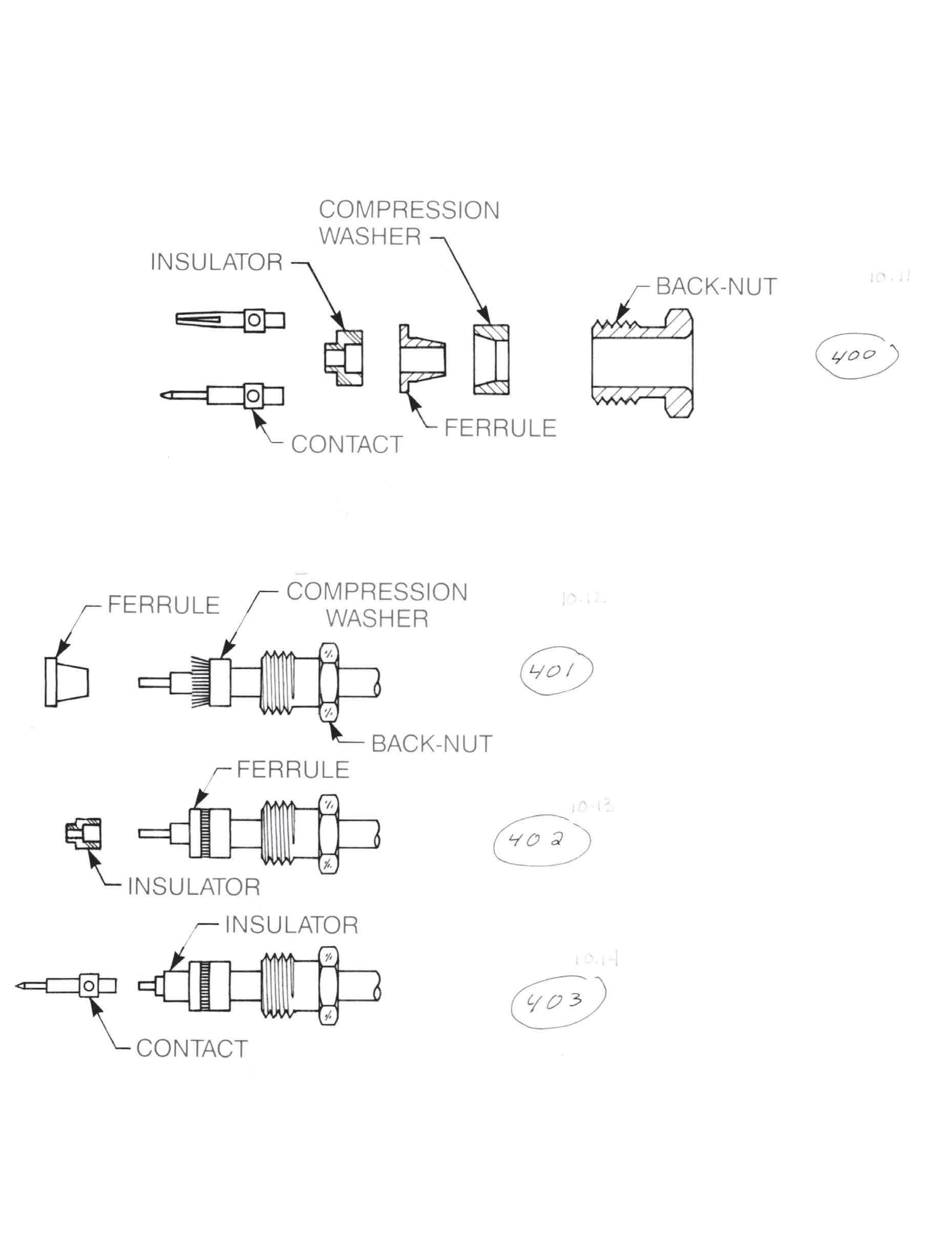
Simplification is Our Innovation.
5) Fan out braid radially against the compression washer by rotating the cable dielectric.
Slide ferrule onto cable, over dielectric and under braid. Push into washer until it stops. If necessary trim
CABLE ASSEMBLIES
Solder contact to center conductor. When contact adapter is also supplied, install contact adapter onto
9) Insert cable assembly into body and tighten nut with a torque of 90-100 inch-ounces on the 50 ohm impedance sizes and 140-150 inch-ounces on the 75 ohm impedance sizes.
13-15
Go online for data sheets and assembly instructions. Visit www.radiall.com/AEP and enter the part number.
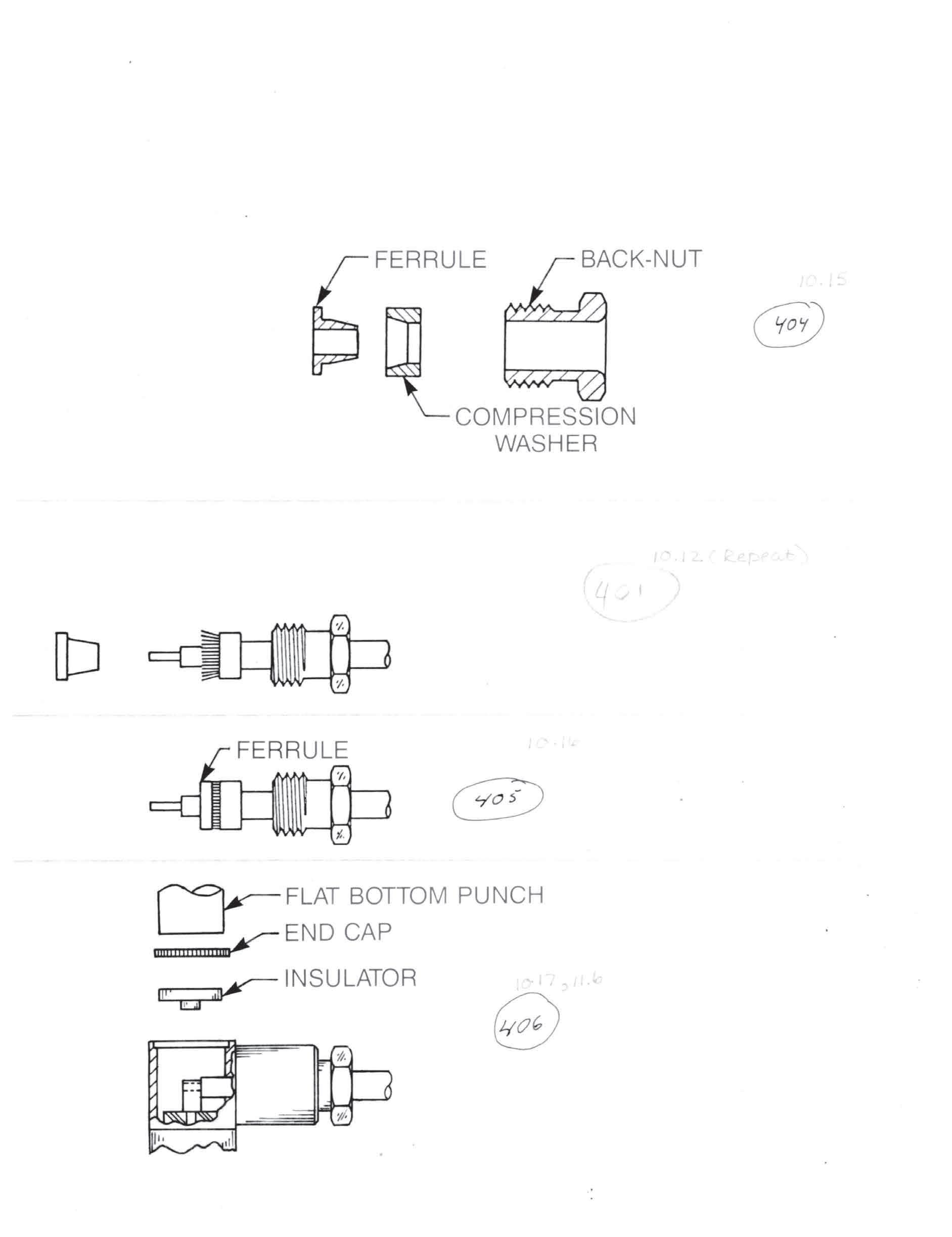
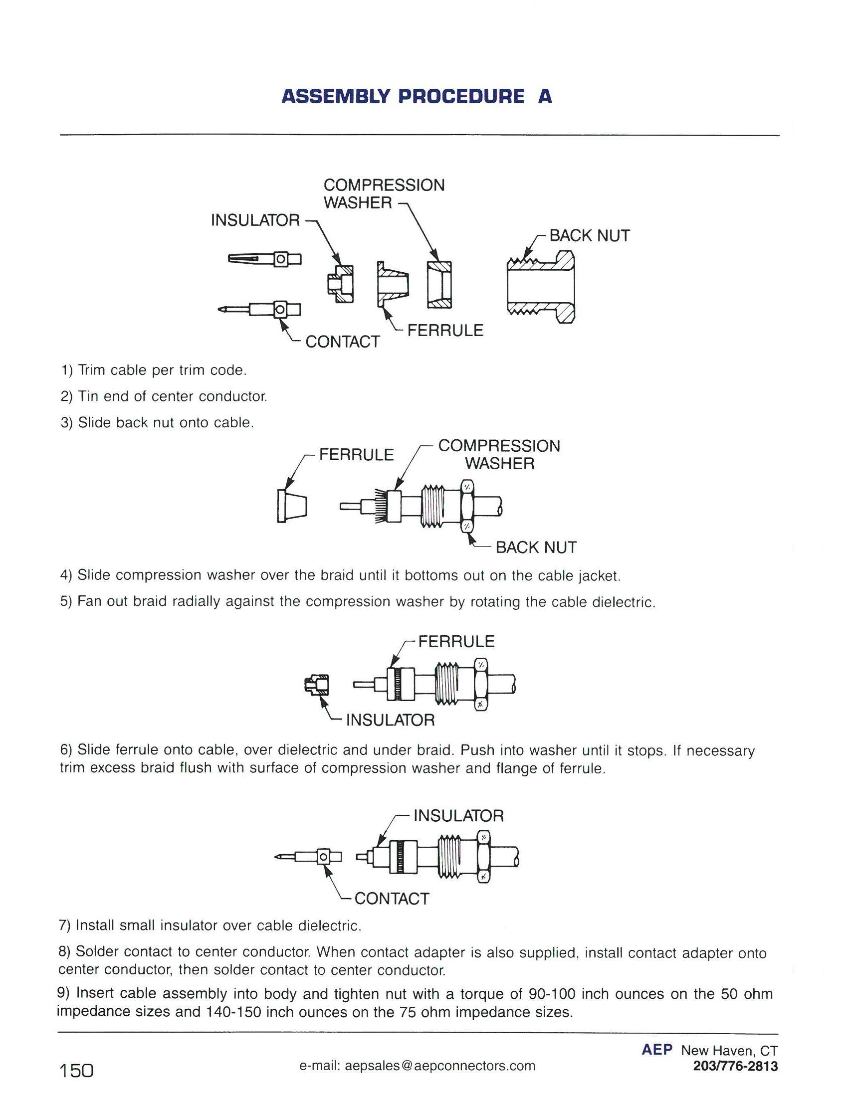

4) Slide compression washer over the braid until it bottoms out on the cable jacket.
5) Fan out braid radially against the compression washer by rotating the cable dielectric.
Slide ferrule onto cable, over dielectric and under braid. Push into washer until it stops. If necessary trim excess braid flush with surface of compression washer and flange of ferrule.
Insert cable assembly into body and tighten nut with a torque of 90-100 inch-ounces on the 50 ohm impedance sizes and 140-150 inch-ounces on the 75 ohm impedance sizes.
8) Solder center conductor of cable to contact.
9) Place insulator and end cap into connector body as shown and use a 0.185˝ diameter flat bottom arbor to press cap into place. Cap must be below body surface to seat properly.
13-16 Go online for data sheets and assembly instructions. Visit www.radiall.com/AEP and enter the part number.
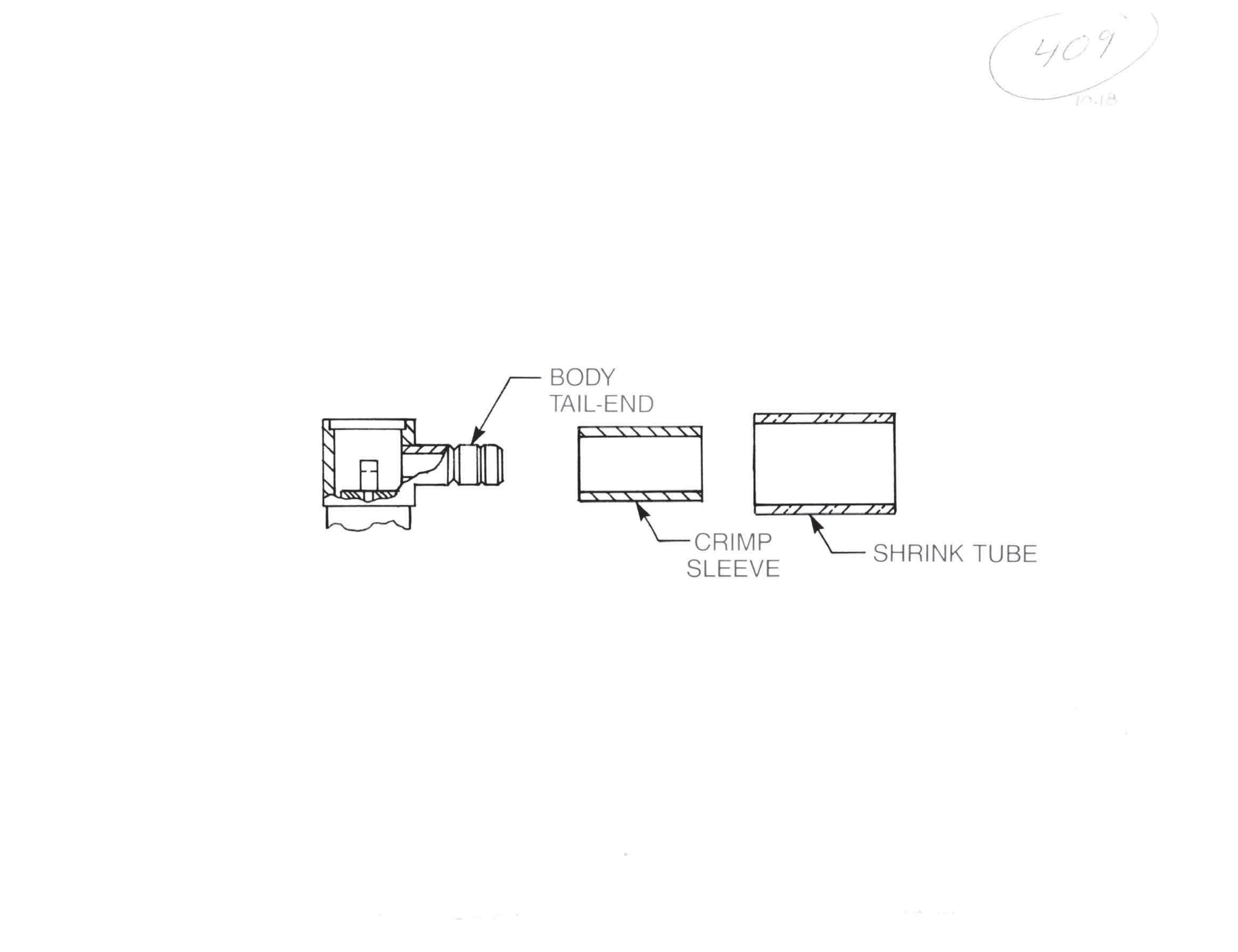
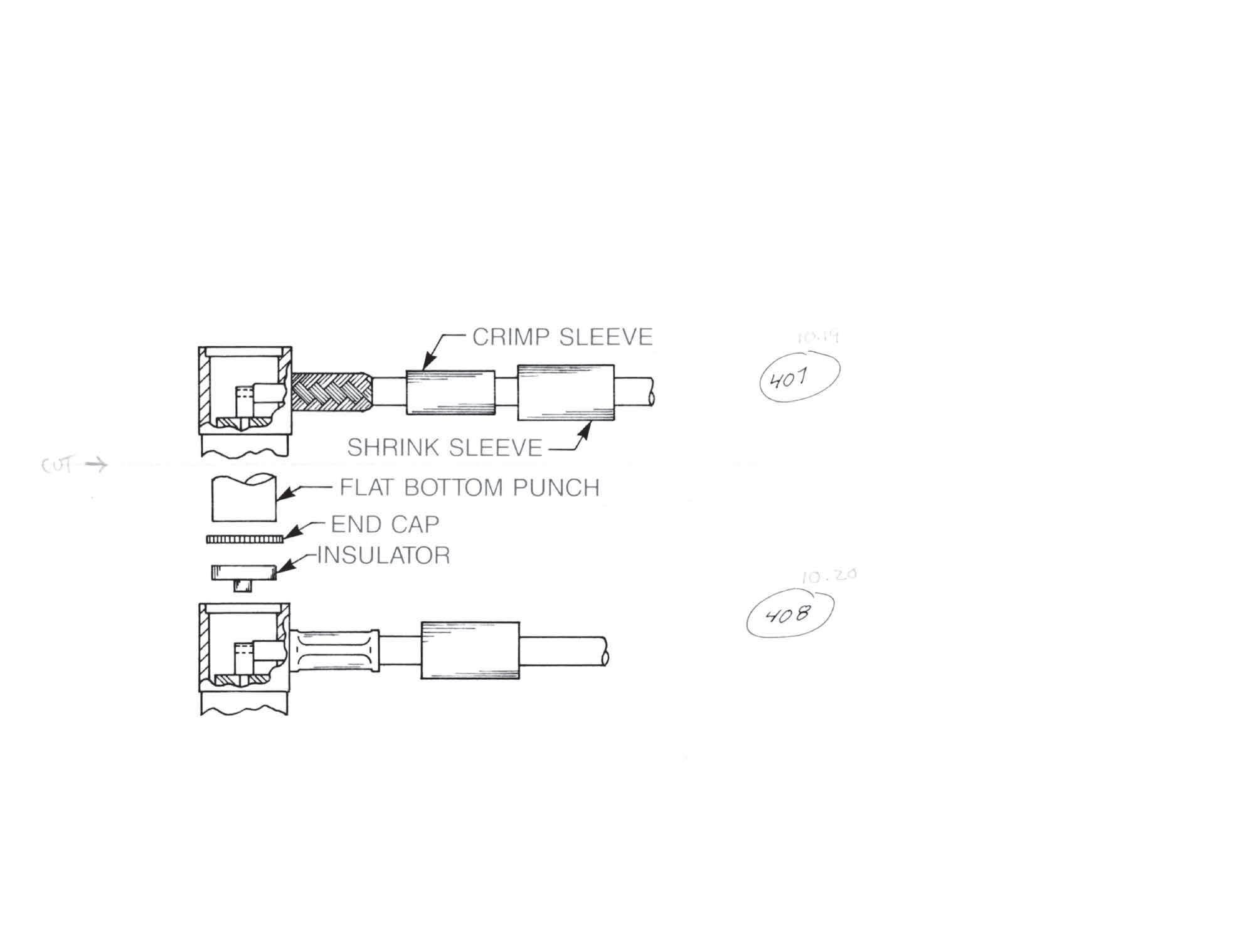
Simplification is Our Innovation.
CABLE ASSEMBLIES
Insert cable assembly into body tail-end making sure tail goes over dielectric and under braid. Slide in until
6) Slide crimp sleeve forward and use applicable hex die to crimp sleeve to braid.
8) Place insulator and end cap into connector body as shown and use a 0.185˝ diameter flat bottom punch to press cap in place. Cap must be below surface to seat properly.
9) Slide shrink tube over crimp sleeve and shrink to fit.
13-17
Go online for data sheets and assembly instructions. Visit www.radiall.com/AEP and enter the part number.
Follow Procedure C, except step 6. At this step, slide sleeve forward and use applicable hex die to crimp sleeve
ASSEMBLY PROCEDURE: E
(Continued on next page)
Visit www.radiall.com/AEP and enter the part number.
Simplification is Our Innovation.
Insert cable into tail-end of back nut, making sure tail goes over dielectric and under braid. Slide in until braid
CABLE ASSEMBLIES
Insert cable assembly into body and tighten nut with a torque wrench with a torque of 70-100 inch-ounces on the 50 ohm impedance sizes and 140-150 inch-ounces on the 75 ohm sizes. 35-45 inch-ounces for SSMB and SSMC series.
10) Slide shrink tube over crimp sleeve and shrink to fit.
13-19
Go online for data sheets and assembly instructions. Visit www.radiall.com/AEP and enter the part number.
CABLE ASSEMBLIES
ASSEMBLY PROCEDURE: F
Note: On cable group -002, an additional sleeve and insulator are supplied.
5) Solder contact to center conductor, leaving a 0.015˝ gap between rear of contact and cable dielectric.
6) Insert cable into tail-end of body, making sure the body goes over dielectric and under the braid.
(Continued on next page)
13-20
Go online for data sheets and assembly instructions. Visit www.radiall.com/AEP and enter the part number.
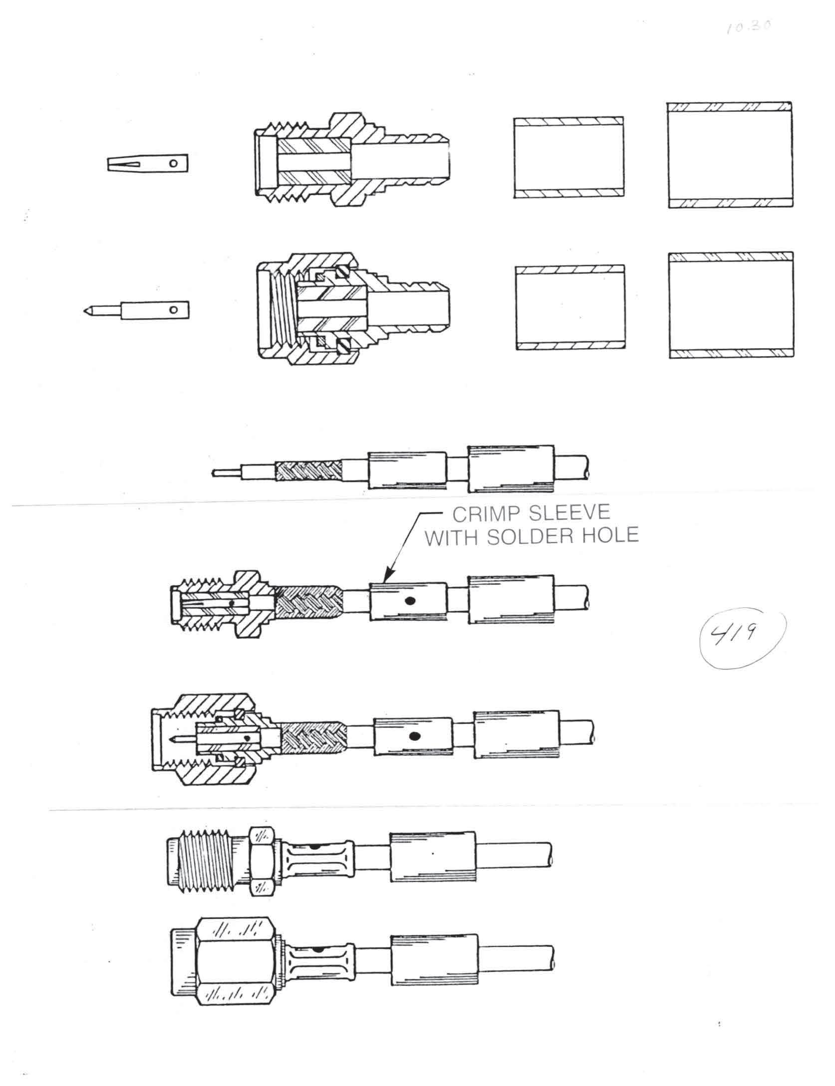
Simplification is Our Innovation.
CABLE ASSEMBLIES
Follow Procedure F, except step 8. At this step, slide crimp sleeve forward and use applicable hex die to crimp.
13-21
Go online for data sheets and assembly instructions. Visit www.radiall.com/AEP and enter the part number.
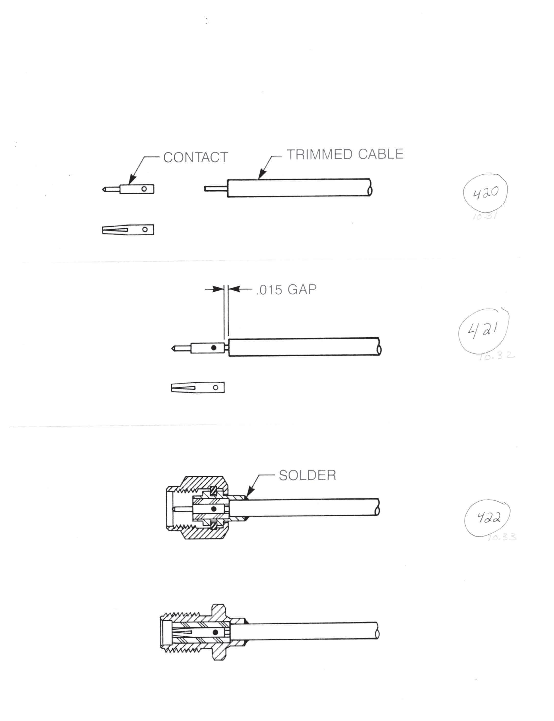
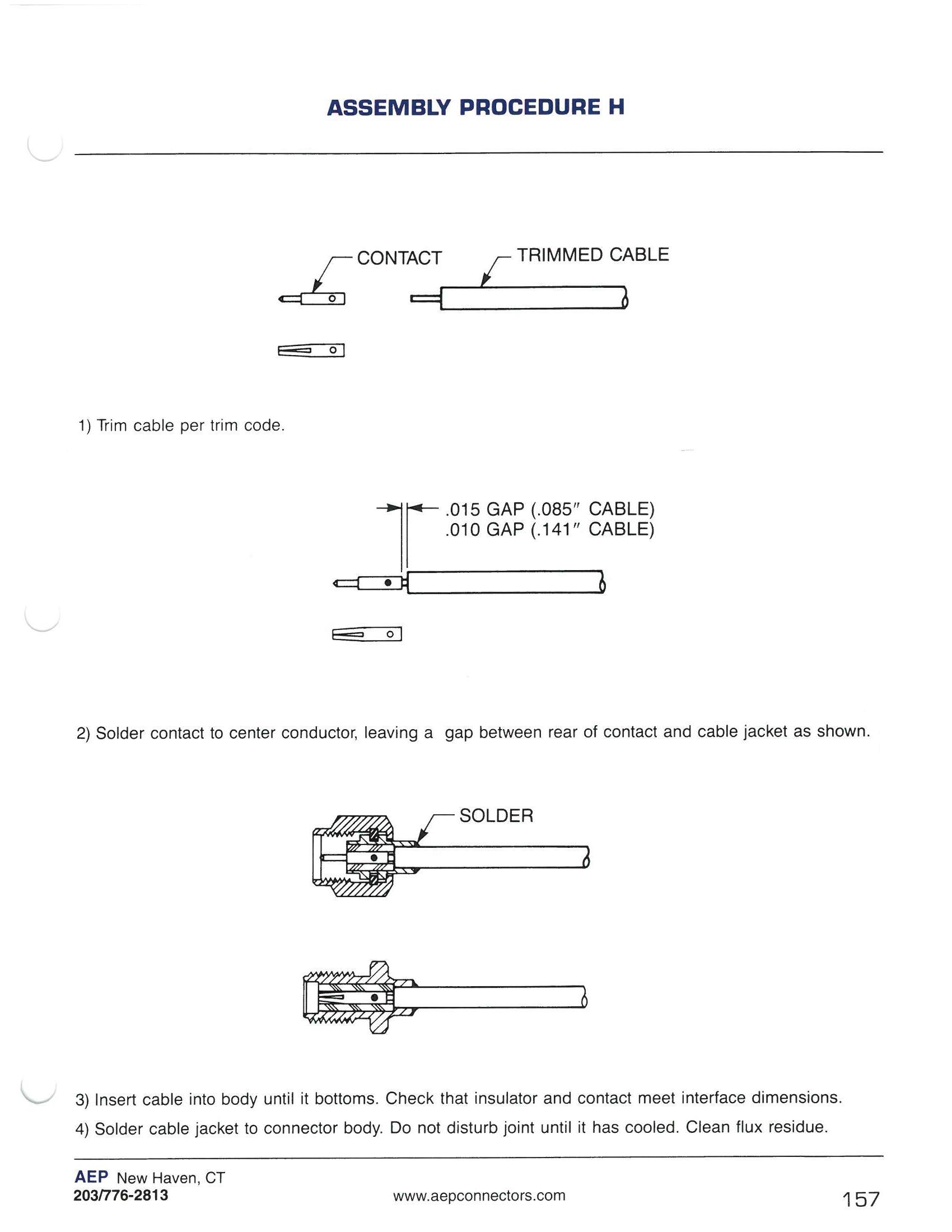
2) Solder contact to center conductor, leaving a gap between rear of contact and cable jacket as shown.
3) Insert cable into body until it bottoms. Check that insulator and contact meet interface dimensions.
4) Solder cable jacket to connector body. Do not disturb joint until it has cooled. Clean flux residue.
Visit www.radiall.com/AEP and enter the part number.

3) Insert cable into body until trimmed end is flush with interface. Fixture in this position.
4) Solder cable jacket to connector body. Do not disturb joint until it has cooled. Clean flux residue.
CABLE ASSEMBLIES
13-23
Visit www.radiall.com/AEP and enter the part number.
Simplification is Our Innovation.

4) Solder ferrule to cable jacket. Do not disturb solder joint until it has cooled.
7) Insert cable assembly into connector body and tighten back nut to 90-100 inch-ounces torque for SMB and SMC, 140-150 inch-ounces torque tor SMA.
13-24 Go online for data sheets and assembly instructions. Visit www.radiall.com/AEP and enter the part number.
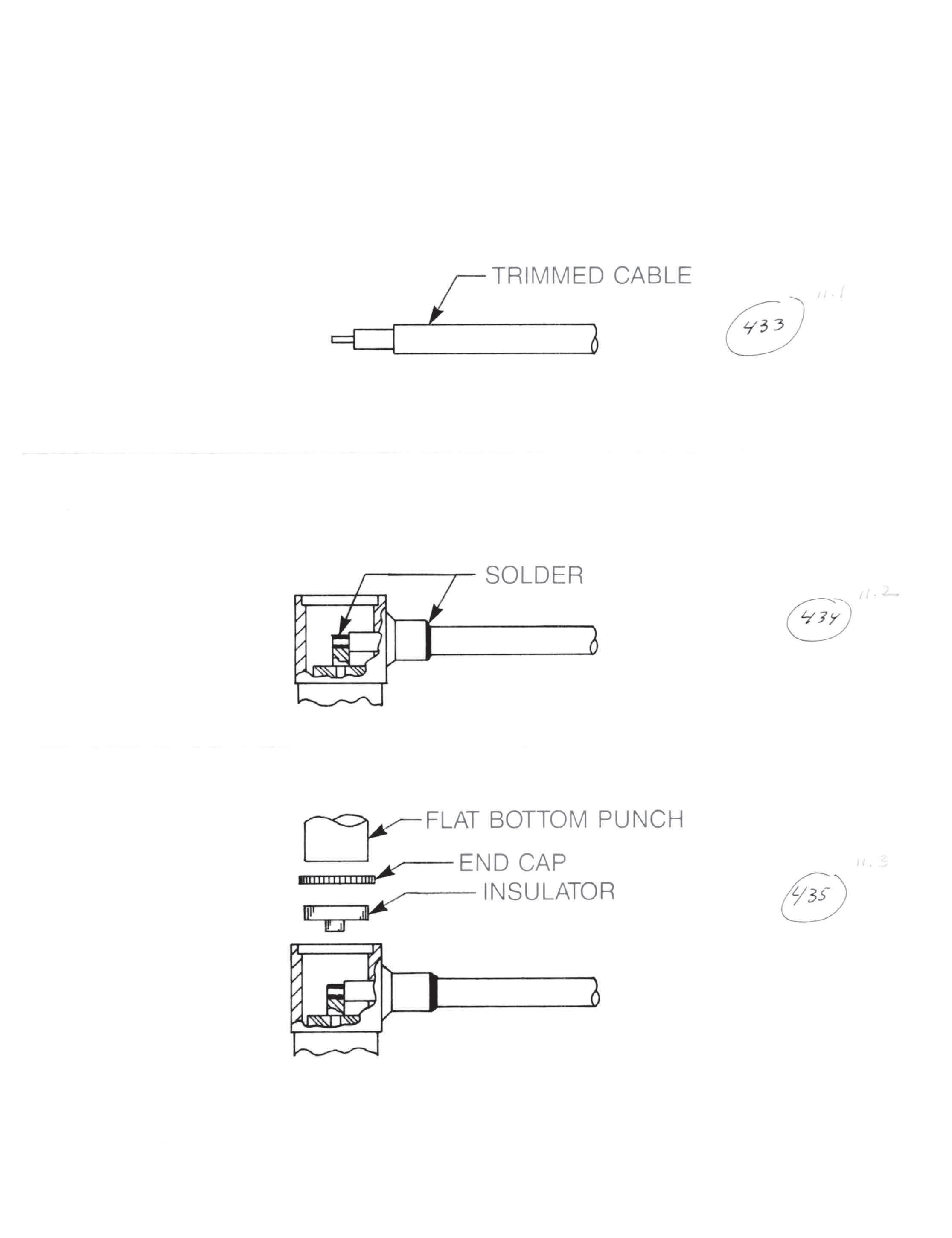
Simplification is Our Innovation.
Insert cable into body. Cable jacket should bottom on step inside body and center conductor should lie in
CABLE ASSEMBLIES
Press insulator and end cap into connector body and use a 0.185˝ diameter flat bottom arbor to press cap
13-25
Go online for data sheets and assembly instructions. Visit www.radiall.com/AEP and enter the part number.
4) Solder cable jacket to connector body. Do not disturb joint until it has cooled. Clean flux residue.
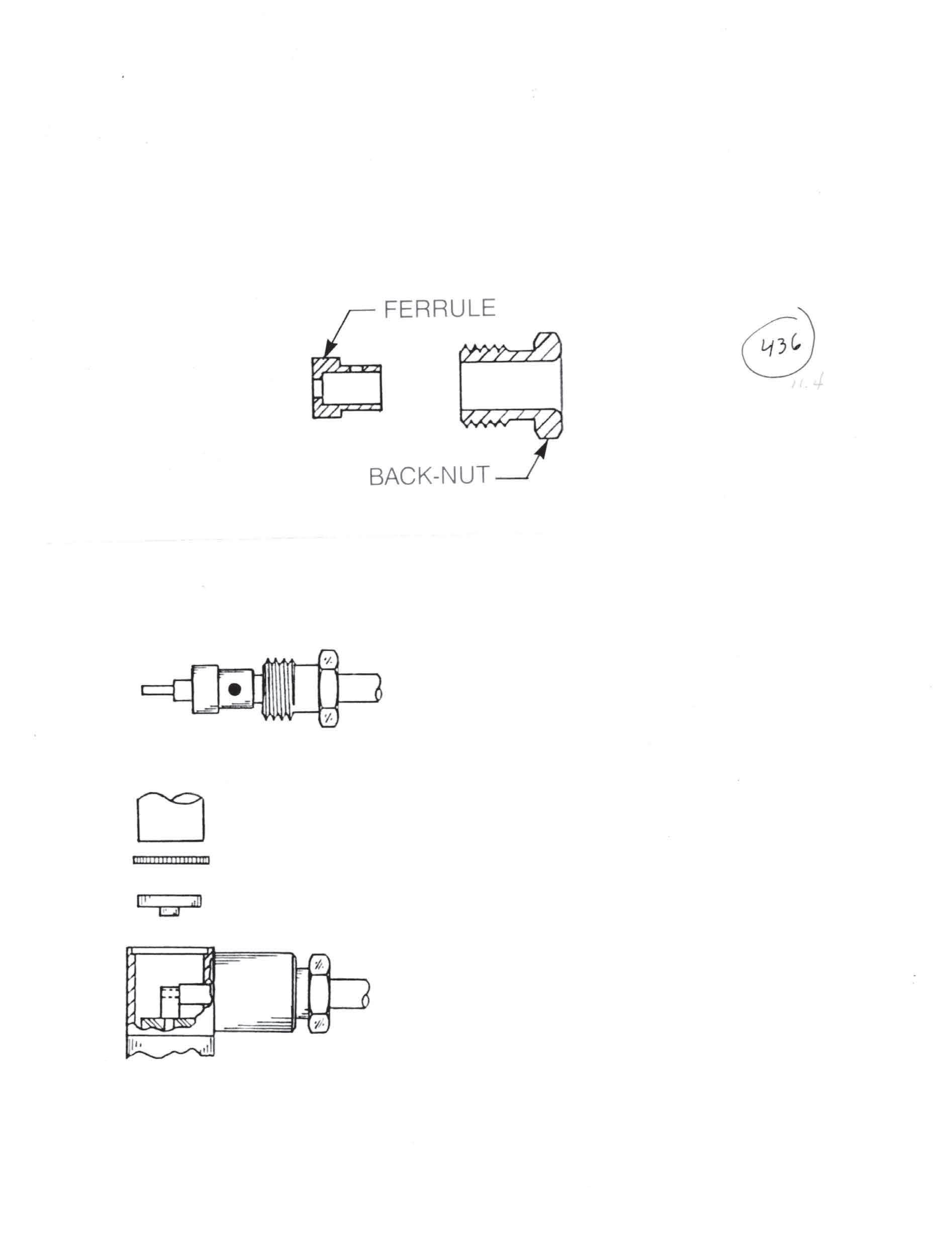
ASSEMBLY PROCEDURE: L

4) Solder ferrule to cable jacket. Do not disturb solder joint until it has cooled. Insert cable assembly into body and tighten to 90-100 inch-ounces torque for SMB and SMC, 140-150
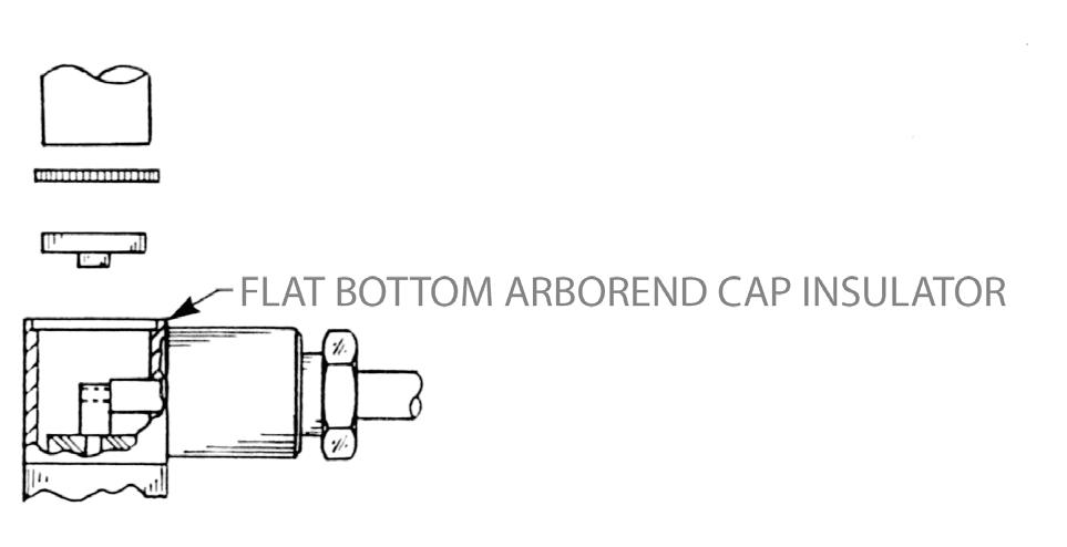
6) Solder center conductor to contact.
7) Press insulator and end cap into connector body and use a 0.185˝ diameter flat bottom arbor to press cap in place. Cap must be below body surface to seat properly.
13-26 Go online for data sheets and assembly instructions. Visit www.radiall.com/AEP and enter the part number.
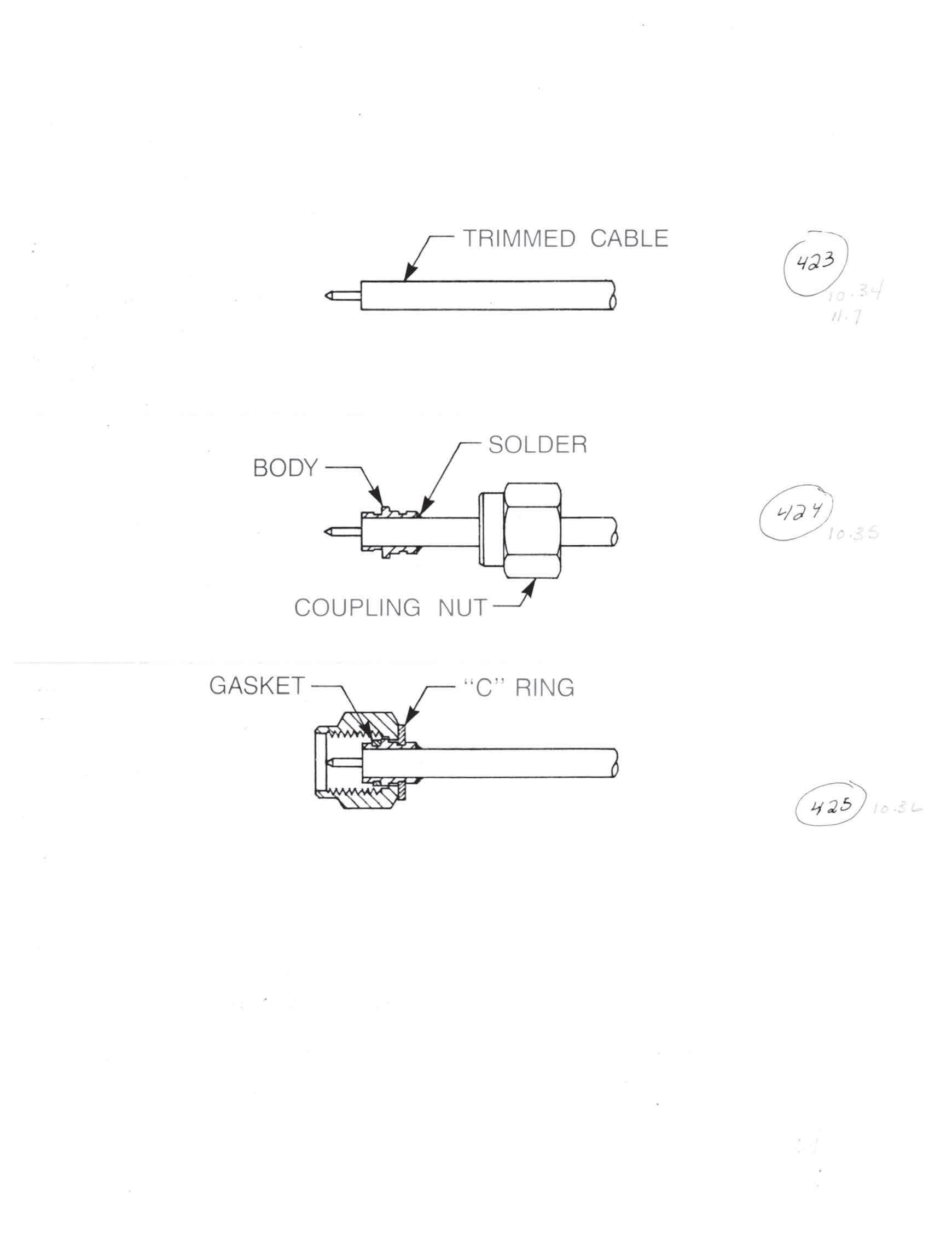
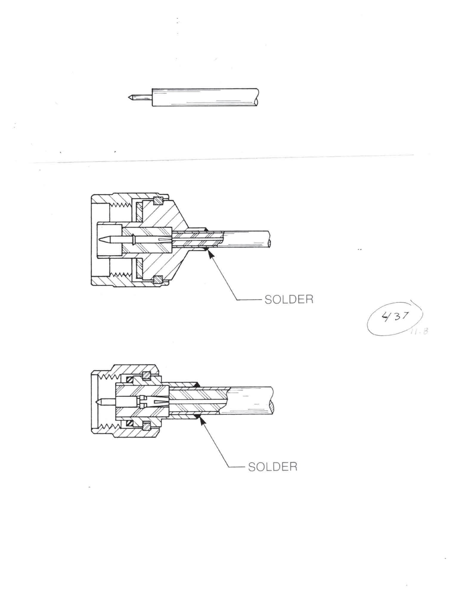
2) Insert cable into body until it bottoms, making sure center conductor of cable goes into contact.
3) Solder cable jacket to connector body. Do not disturb joint until it has cooled. Clean flux residue.
CABLE ASSEMBLIES
13-27
Go online for data sheets and assembly instructions. Visit www.radiall.com/AEP and enter the part number.
Simplification is Our Innovation.
Insert cable into body until cable dielectric is flush with interface. Cable jacket should bottom on step inside
4) Solder cable jacket to connector body. Do not disturb joint until it has cooled. Clean flux residue.
13-28 Go online for data sheets and assembly instructions. Visit www.radiall.com/AEP and enter the part number.
3) Slide ferrule over cable dielectric until it bottoms on the cable jacket.
4) Solder ferrule to cable jacket. Do not disturb solder joint until it has cooled.
Simplification is Our Innovation.
5) Install small insulator over cable dielectric (one applies for 0.085 semi-rigid cable).
Trim dielectric flush with ferrule, then point center conductor 70° to 90° (only applies to 0.141 diameter
CABLE ASSEMBLIES
Insert cable assembly into body until it bottoms, making sure center conductor of cable goes into
2) Slide back nut onto cable until trimmed end of jacket is flush with front of nut. Solder nut to cable.
5) Insert cable assembly into connector body and tighten to 35-45 inch-ounces torque.
13-29
Visit www.radiall.com/AEP and enter the part number.
NOTES
Go online for data sheets and assembly instructions. Visit www.radiall.com/AEP and enter the part number.

SIMPLIFICATION IS OUR INNOVATON Visit www.radiall.com for more information. SECTION 14
TOOLING
14-1 Simplification is Our Innovation. Go online for data sheets and assembly instructions. Visit www.radiall.com/AEP and enter the part number. SECTION 14 TABLE OF CONTENTS Crimp Tools 14-2 Torque Wrenches 14-2 SMA Interface Gages 14-3

SMA INTERFACE GAGES
SMA interface dimensions are critical to connector performance and are largely determined by correct cable assembly procedure. We strongly recommend the use of interface gages after cable assembly to prevent damage to equipment mounted jacks at installation.
The gages shown here are "right reading", giving a minus indication for interface components below the reference plane, and a plus indication for components above the reference plane. Standard dial indicators read the opposite way and can be confusing for operators.
These gages are accurate to 0.00025 inches, have graduation values of 0.0005 inches and are zero-set before shipment. Replacement parts and master zero-setting gages are available.
Part numbers:
TA-0396: Set of four gages listed below, in padded wooden box with instruction booklet
TA-0396-1: SMA plug insulator gage
TA-0396-2: SMA plug contact gage
TA-0396-3: SMA jack insulator gage SMA jack contact gage
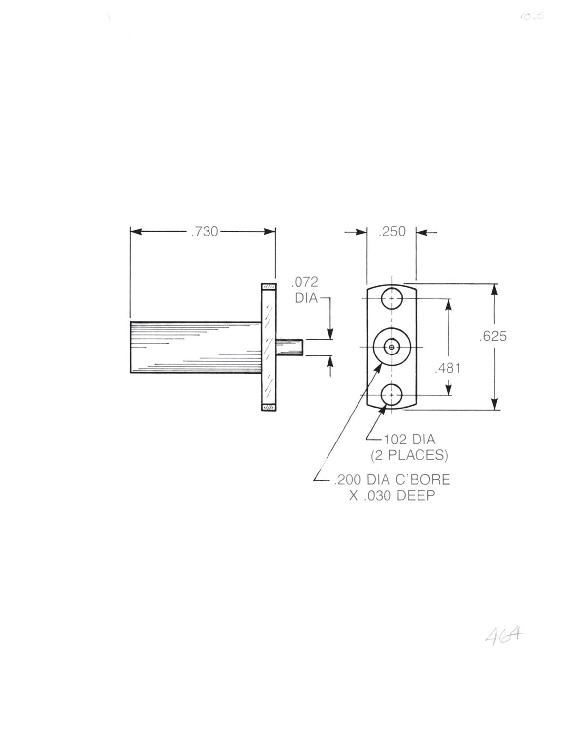
This tool can be used with any hermetic seal, except for 920-92. The spring-loaded plunger holds the seal in place during the soldering operation.
Part number: TA-0394
14-3 Visit www.radiall.com/AEP and enter the part number.
Hermetic Seal Soldering Tool
P/N TA-0396-1 P/N TA-0396-2 P/N TA-0396-3 P/N TA-0396-4
NOTES
Go online for data sheets and assembly instructions. Visit www.radiall.com/AEP and enter the part number.
PART
SIMPLIFICATION IS OUR INNOVATON Visit www.radiall.com for more information. INDEX
NUMBER INDEX
1001-1541-009 .............. J .............. 113 ...... 3-18
1001-1541-010 J 112 3-18
1001-1551-002 A 1 3-18
1001-1551-003 .............. A ................ 1 ........ 3-18
1001-1551-005 A 1 3-18
1001-1551-019 A 1 3-18
1001-1571-002 .............. E ................ 2 ........ 3-18
1001-1571-003 E 2 3-18
1001-1571-005 E 2 3-18
1001-1571-019 .............. E ................ 2 ........ 3-18
1001-7541-009 J 113 3-18
1001-7541-010 J 112 3-18
1001-7551-002 .............. A ................ 1 ........ 3-18
1001-7551-003 A 1 3-18
1001-7551-005 A 1 3-18
1001-7551-019 A 1 3-18
1001-7571-002 E 2 3-18
1001-7571-003 ............. E ................ 2 ........ 3-18
1001-7571-005 E 2 3-18
1001-7571-019 E 2 3-18
1002-1541-009 .............. J .............. 113 ...... 3-17
1002-1541-010 J 112 3-17
1002-1551-002 A 1 3-17
1002-1551-003 .............. A ................ 1 ........ 3-17
1002-1551-005 A 1 3-17
1002-1551-019 A 1 3-17
1002-1571-002 .............. E ................ 2 ........ 3-17
1002-1571-003 E 2 3-17
1002-1571-005 E 2 3-17
1002-1571-019 .............. E ................ 2 ........ 3-17
1002-7541-009 J 113 3-17
1002-7541-010 J 112 3-17
1002-7551-002 ............. A ................ 1 ........ 3-17
1002-7551-003 A 1 3-17
1002-7551-005 A 1 3-17
1002-7551-019 .............. A ................ 1 ........ 3-17
1002-7571-002 E 2 3-17
1002-7571-003 ............. E ................ 2 ........ 3-17
1002-7571-005 E 2 3-17
1002-7571-019 E 2 3-17
1003-1541-009.............. J .............. 113 ...... 3-19
1003-1541-010 J 112 3-19
1003-1551-002 A 1 3-19
1003-1551-003 ............. A ................ 1 ........ 3-19
1003-1551-005 A 1 3-19
1003-1551-019 A 1 3-19
1003-1571-002 ............. E ................ 2 ........ 3-19
1003-1571-003 E 2 3-19
1003-1571-005 E 2 3-19
1003-1571-019 .............. E ................ 2 ........ 3-19
1003-7541-009 J 113 3-19
1003-7541-010 J 112 3-19
1003-7551-002 ............. A ................ 1 ........ 3-19
1003-7551-003 A 1 3-19
1003-7551-005 A 1 3-19
1003-7551-019 A 1 3-19
1003-7571-002 E 2 3-19
1003-7571-003 ............. E ................ 2 ........ 3-19
1003-7571-005 E 2 3-19
1003-7571-019 E 2 3-19
1004-1511-000 ............ N/A ............ N/A ...... 3-20
1004-7511-000 N/A N/A 3-20
1005-1541-009 L 120 3-17
1005-1541-010 .............. L .............. 120 ...... 3-17
1005-1551-002 B 3 3-17
1005-1551-003 B 3 3-17
1005-1551-005.............. B................ 3 ........ 3-17
1005-1551-019 B 3 3-17
1005-7541-009 L 120 3-17
1005-7541-010 .............. L .............. 120 ...... 3-17
1005-7551-002 B 3 3-17
1005-7551-003 B 3 3-17
1005-7551-005 ............. B................ 3 ........ 3-17
1005-7551-019 B 3 3-17
15-1
ASSEMBLY
TRIM CODE TRIM CODE PAGE PART NUMBER PAGE Go online for data sheets and assembly instructions. Visit www.radiall.com/AEP and
the part number.
AEP P/N INDEX Simplification is Our Innovation. PART NUMBER ASSEMBLY PROCEDURE
PROCEDURE
enter
1006-1541-009 .............. L .............. 120 ...... 3-19
1006-1541-010 L 120 3-19
1006-1551-002 B 3 3-19
1006-1551-003.............. B................ 3 ........ 3-19
1006-1551-005 B 3 3-19
1006-1551-019 B 3 3-19
1006-7541-009 ............. L .............. 120 ...... 3-19
1006-7541-010 L 120 3-19
1006-7551-002 B 3 3-19
1006-7551-003 ............. B................ 3 ........ 3-19
1006-7551-005 B 3 3-19
1006-7551-019 B 3 3-19
1009-1511-000 ............ N/A ............ N/A ...... 3-21
1009-7511-000 N/A N/A 3-21
1010-1511-000 N/A N/A 3-21
1010-1511-001 N/A N/A 3-21
1010-7511-000 N/A N/A 3-21
1010-7511-001 ............ N/A ............ N/A ...... 3-21
1012-1511-000 N/A N/A 3-20
1012-7511-000 N/A N/A 3-20
1017-1511-000 ............ N/A ............ N/A ...... 3-20
1017-7511-000 N/A N/A 3-20
1019-1511-000 N/A N/A 3-20
1019-7511-000 ............ N/A ............ N/A ...... 3-20
1025-1511-000 N/A N/A 3-21
1025-7511-000 N/A N/A 3-21
1029-1211-001 ............ N/A ............ N/A ...... 3-23
1029-1211-002 N/A N/A 3-23
1029-1211-003 N/A N/A 3-23
1029-7211-001 ............ N/A ............ N/A ...... 3-23
1029-7211-002 N/A N/A 3-23
1029-7211-003 N/A N/A 3-23
1036-1511-051 ............ N/A ............ N/A ...... 3-25
1036-7511-051 N/A N/A 3-25
1037-1511-051 N/A N/A 3-25
1037-7511-051 ............ N/A ............ N/A ...... 3-25
1041-1541-009 L 120 3-18
1109-1511-000
15-2
P/N INDEX PART NUMBER ASSEMBLY PROCEDURE ASSEMBLY PROCEDURE TRIM CODE TRIM CODE PAGE PART NUMBER PAGE Go online for data sheets and assembly instructions. Visit www.radiall.com/AEP and enter the part number.
AEP
1041-1541-010 .............. L .............. 120 ...... 3-18 1041-1551-002 B 3 3-18 1041-1551-003 B 3 3-18 1041-1551-005 .............. B................ 3 ........ 3-18
1041-1551-019 B 3 3-18 1041-7541-009 L 120 3-18 1041-7541-010 .............. L .............. 120 ...... 3-18
N/A N/A 3-23 1092-1511-002 N/A N/A 3-23 1092-1511-003 ............ N/A ............ N/A ...... 3-23 1092-7511-001
1092-7511-002
1092-7511-003
3-23
C 4 3-17
C
4 ........ 3-17
4 3-17
1041-7551-002 B 3 3-18 1041-7551-003 B 3 3-18 1041-7551-005 .............. B................ 3 ........ 3-18 1041-7551-019 B 3 3-18 1042-1511-000 N/A N/A 3-21 1042-7511-000 ............ N/A ............ N/A ...... 3-21 1092-1511-001
N/A N/A 3-23
N/A N/A 3-23
N/A N/A
1105-1521-002
1105-1521-003 ..............
................
1105-1521-005 C
1105-1521-019 C 4 3-17
1105-7521-002 .............. C ................ 4 ........ 3-17 1105-7521-003 C 4 3-17
C ................ 4 ........ 3-17
C 4 3-19
4 3-19
1105-7521-005 C 4 3-17 1105-7521-019 ..............
1106-1521-002
1106-1521-003 C
1106-1521-005 .............. C ................ 4 ........ 3-19 1106-1521-019 C 4 3-19 1106-7521-002 C 4 3-19
1106-7521-003.............. C ................ 4 ........ 3-19
1106-7521-005 C 4 3-19
1106-7521-019 C 4 3-19
............ N/A ............ N/A ...... 3-22 1109-7511-000 N/A N/A 3-22
1110-1511-000............. N/A ............ N/A ...... 3-22
1110-7511-000 N/A N/A 3-22
1141-1521-002 C 4 3-18
1141-1521-003 .............. C ................ 4 ........ 3-18
1141-1521-005 C 4 3-18
1141-1521-019 C 4 3-18
1141-7521-002 .............. C ................ 4 ........ 3-18
1141-7521-003 C 4 3-18
1141-7521-005 C 4 3-18
1141-7521-019 .............. C ................ 4 ........ 3-18
1484-1511-000 N/A N/A 3-22
1484-7511-000 N/A N/A 3-22
1486-1511-000 ............ N/A ............ N/A ...... 3-22
1486-7511-000 N/A N/A 3-22
1488-1511-000 N/A N/A 3-22
1488-7511-000 N/A N/A 3-22
1490-1511-000 N/A N/A 3-22
1490-7511-000 ............ N/A ............ N/A ...... 3-22
1701-1551-003 A 5 6-5
1701-1551-004 A 5 6-5
1701-1551-007 .............. A ................ 5 .......... 6-5
1701-1571-003 E 6 6-5
1701-1571-004 E 6 6-5
1701-1571-007 .............. E ................ 6 .......... 6-5
1701-7551-003 A 5 6-5
1701-7551-004 A 5 6-5
1701-7551-007 .............. A ................ 5 .......... 6-5
1701-7571-003 E 6 6-5
1701-7571-004 E 6 6-5
1701-7571-007 .............. E ................ 6 .......... 6-5
1702-1551-003 A 5 6-4
1702-1551-004 A 5 6-4
1702-1551-007 .............. A ................ 5 .......... 6-4
1702-1571-003 E 6 6-4
1702-1571-004 E 6 6-4
1702-1571-007 .............. E ................ 6 .......... 6-4
1702-7551-003 A 5 6-4
1702-7551-004 ............. A ................ 5 .......... 6-4
1702-7551-007 A 5 6-4
1702-7571-003 E 6 6-4
1702-7571-004 ............. E ................ 6 .......... 6-4
1702-7571-007 E 6 6-4
1703-1551-003 A 5 6-5
1703-1551-004.............. A ................ 5 .......... 6-5
1703-1551-007 A 5 6-5 1703-1571-003 E 6 6-5
1703-1571-004.............. E ................ 6 .......... 6-5
1703-1571-007 E 6 6-5
1703-7551-003 A 5 6-5
1703-7551-004 ............. A ................ 5 .......... 6-5
1703-7551-007 A 5 6-5
1703-7571-003 E 6 6-5
1703-7571-004 ............. E ................ 6 .......... 6-5
1703-7571-007 E 6 6-5
1704-1511-000 N/A N/A 6-6
1704-7511-000 N/A N/A 6-6
1705-1551-003 B 7 6-4
1705-1551-004 .............. B................ 7 .......... 6-4
1705-1551-007 B 7 6-4
1705-7551-003 B 7 6-4
1705-7551-004 ............. B................ 7 .......... 6-4
1705-7551-007 B 7 6-4
1709-1511-000 N/A N/A 6-6
1709-7511-000 ............ N/A ............ N/A ........ 6-6
1710-1511-000 N/A N/A 6-6
1710-7511-000 N/A N/A 6-6
1715-1521-003 .............. C ................ 8 .......... 6-4
1715-1521-004 C 8 6-4
1715-1521-007 C 8 6-4
1715-7521-003 .............. C ................ 8 .......... 6-4
1715-7521-004 C 8 6-4
1715-7521-007 C 8 6-4
1719-1511-000 ............ N/A ............ N/A ........ 6-6
1719-7511-000 N/A N/A 6-6
15-3
ASSEMBLY
TRIM CODE TRIM CODE PAGE PART NUMBER PAGE Go online for data sheets and assembly instructions. Visit www.radiall.com/AEP and enter the part number.
AEP P/N INDEX Simplification is Our Innovation. PART NUMBER ASSEMBLY PROCEDURE
PROCEDURE
15-4 AEP P/N INDEX PART NUMBER ASSEMBLY PROCEDURE ASSEMBLY PROCEDURE TRIM CODE TRIM CODE PAGE PART NUMBER PAGE Go online for data sheets and assembly instructions. Visit www.radiall.com/AEP and enter the part number.
............ N/A ............ N/A ........ 6-7
N/A N/A 6-7 2001-1541-009 J 113 3-8 2001-1541-010 .............. J .............. 112 ........ 3-8 2001-1551-002 A 1 3-8 2001-1551-003 A 1 3-8 2001-1551-005 .............. A ................ 1 .......... 3-8 2001-1551-019 A 1 3-8 2001-1551-903 E 2 1-4 2001-1571-002 .............. E ................ 2 .......... 3-8 2001-1571-003 E 2 3-8 2001-1571-005 E 2 3-8 2001-1571-019 .............. E ................ 2 .......... 3-8 2001-1571-803 E 2 1-4 2001-1571-903 E 2 1-4 2001-7541-009 J 113 3-8 2001-7541-010 J 112 3-8 2001-7551-002 ............. A ................ 1 .......... 3-8 2001-7551-003 A 1 3-8 2001-7551-005 A 1 3-8 2001-7551-019 .............. A ................ 1 .......... 3-8 2001-7571-002 E 2 3-8
E 2 3-8 2001-7571-005 ............. E ................ 2 .......... 3-8 2001-7571-019 E 2 3-8 2002-1541-009 J 113 3-6
.............. J .............. 112 ........ 3-6 2002-1551-002 A 1 3-6 2002-1551-003 A 1 3-6 2002-1551-005 ............. A ................ 1 .......... 3-6 2002-1551-019 A 1 3-6 2002-1551-903 A 1 1-3
............. E ................ 2 .......... 3-6 2002-1571-003 E 2 3-6 2002-1571-005 E 2 3-6 2002-1571-019 .............. E ................ 2 .......... 3-6 2002-1571-803 E 2 1-4
E ................ 2 .......... 1-3 2002-7541-009 J 113 3-6 2002-7541-010 J 112 3-6 2002-7551-002 ............. A ................ 1 .......... 3-6 2002-7551-003 A 1 3-6 2002-7551-005 A 1 3-6 2002-7551-019.............. A ................ 1 .......... 3-6 2002-7571-002 E 2 3-6 2002-7571-003 E 2 3-6 2002-7571-005 ............. E ................ 2 .......... 3-6 2002-7571-019 E 2 3-6 2003-1541-009 J 113 3-9 2003-1541-010 .............. J .............. 112 ........ 3-9 2003-1551-002 A 1 3-9 2003-1551-003 A 1 3-9 2003-1551-005 ............. A ................ 1 .......... 3-9 2003-1551-019 A 1 3-9 2003-1551-903 A 1 1-4 2003-1571-002 E 2 3-9 2003-1571-003 E 2 3-9 2003-1571-005 ............. E ................ 2 .......... 3-9 2003-1571-019 E 2 3-9 2003-7541-009 J 113 3-9 2003-7541-010 ............. J .............. 112 ........ 3-9
A 1 3-9
A 1 3-9 2003-7551-005 ............. A ................ 1 .......... 3-9 2003-7551-019 A 1 3-9 2003-7571-002 E 2 3-9 2003-7571-003 ............. E ................ 2 .......... 3-9 2003-7571-005 E 2 3-9 2003-7571-019 E 2 3-9 2004-1511-000 ............ N/A ............ N/A ...... 3-10 2004-1511-999 N/A N/A 1-5
N/A N/A 3-10
............. L .............. 120 ........ 3-6 2005-1541-010 L 120 3-6
1736-1511-075
1736-7511-075
2001-7571-003
2002-1541-010
2002-1571-002
2002-1571-903..............
2003-7551-002
2003-7551-003
2004-7511-000
2005-1541-009
2005-1551-002 ............. B................ 3 .......... 3-6
2005-1551-003 B 3 3-6
2005-1551-005 B 3 3-6
2005-1551-019 .............. B................ 3 .......... 3-6
2005-1551-903 B 3 1-4
2005-7541-009 L 120 3-6
2005-7541-010 ............. L .............. 120 ........ 3-6
2005-7551-002 B 3 3-6
2005-7551-003 B 3 3-6
2005-7551-005 ............. B................ 3 .......... 3-6
2005-7551-019 B 3 3-6
2006-1541-009 L 120 3-9
2006-1541-010 .............. L .............. 120 ........ 3-9
2006-1551-002 B 3 3-9
2006-1551-003 B 3 3-9
2006-1551-005 B 3 3-9
2006-1551-019 B 3 3-9
2006-7541-009 ............. L .............. 120 ........ 3-9
2006-7541-010 L 120 3-9
2006-7551-002 B 3 3-9
2006-7551-003 ............. B................ 3 .......... 3-9
2006-7551-005 B 3 3-9
2006-7551-019 B 3 3-9
2009-1511-000 ............ N/A ............ N/A ...... 3-12
2009-1511-050 N/A N/A 3-12
2009-1511-799 N/A N/A 1-6
2009-1511-899 ............ N/A ............ N/A ........ 1-6
2009-1511-999 N/A N/A 1-6
2009-6511-799 N/A N/A 1-6
2009-7511-000 ........... N/A ............ N/A ...... 3-12
2009-7511-050 N/A N/A 3-12
2010-1511-000 N/A N/A 3-12
2010-1511-002 ............ N/A ............ N/A ...... 3-12
2010-1511-799 N/A N/A 1-6
2010-1511-899 N/A N/A 1-6
2010-1511-999 ............ N/A ............ N/A ........ 1-6
2010-6511-799 N/A N/A 1-6
2010-7511-000 ............ N/A ............ N/A ...... 3-12
2010-7511-002 N/A N/A 3-12
2012-1511-000 N/A N/A 3-10
2012-7511-000 ............ N/A ............ N/A ...... 3-10
2014-1511-000 N/A N/A 3-10
2014-7511-000 N/A N/A 3-10
2017-1511-000 ............ N/A ............ N/A ...... 3-11
2017-7511-000 N/A N/A 3-11
2019-1511-000 N/A N/A 3-10
2019-1511-999 ............ N/A ............ N/A ........ 1-5
2019-7511-000 N/A N/A 3-10
2025-1511-000 N/A N/A 3-12
2025-7511-000 ........... N/A ............ N/A ...... 3-12
2028-1541-009 J 113 3-7
2028-1541-010 J 112 3-7
2028-1551-002 ............. A ................ 1 .......... 3-7
2028-1551-003 A 1 3-7
2028-1551-005 A 1 3-7
2028-1551-019 A 1 3-7
2028-1571-002 E 2 3-7
2028-1571-003 ............. E ................ 2 .......... 3-7
2028-1571-005 E 2 3-7
2028-1571-019 E 2 3-7
2028-7541-009 ............. J .............. 113 ........ 3-7
2028-7541-010 J 112 3-7
2028-7551-002 A 1 3-7
2028-7551-003 ............. A ................ 1 .......... 3-7
2028-7551-005 A 1 3-7
2028-7551-019 A 1 3-7
2028-7571-002 ............. E ................ 2 .......... 3-7
2028-7571-003 E 2 3-7
2028-7571-005 E 2 3-7
2028-7571-019 ............. E ................ 2 .......... 3-7
2029-1211-001 N/A N/A 3-14
2029-1211-002 N/A N/A 3-14
2029-1211-003 ............ N/A ............ N/A ...... 3-14
2029-7211-001 N/A N/A 3-14
15-5
ASSEMBLY
TRIM CODE TRIM CODE PAGE PART NUMBER PAGE Go online for data sheets and assembly instructions. Visit www.radiall.com/AEP
the part number.
AEP P/N INDEX Simplification is Our Innovation. PART NUMBER ASSEMBLY PROCEDURE
PROCEDURE
and enter
2029-7211-002 ........... N/A ............ N/A ...... 3-14
2029-7211-003 N/A N/A 3-14
2036-1511-051 N/A N/A 3-16
2036-7511-051 ............ N/A ............ N/A ...... 3-16
2037-1511-051 N/A N/A 3-16
2037-7511-051 N/A N/A 3-16
2041-1541-009 .............. L .............. 120 ........ 3-8
2041-1541-010 L 120 3-8
2041-1551-002 B 3 3-8
2041-1551-003
2041-1551-005
2041-7551-002
2041-7551-003
2041-7551-005
2041-7551-019
2042-1511-000 N/A N/A 3-12
2042-7511-000 N/A N/A 3-12
2048-1511-000............ N/A ............ N/A ...... 3-11
2048-7511-000 N/A N/A 3-11
2092-1511-001 N/A N/A 3-14
2092-1511-002
2092-1511-003 N/A N/A 3-14
2092-7511-001 N/A N/A 3-14
2092-7511-002............ N/A ............ N/A ...... 3-14
2092-7511-003 N/A N/A 3-14
2097-1511-000 N/A N/A 3-11
2097-7511-000 ............ N/A ............ N/A
2486-7511-000 N/A N/A 3-13
2488-1511-000 N/A N/A 3-13
2488-7511-000
2490-1511-000 N/A N/A 3-13
2701-7551-003
15-6
P/N INDEX PART NUMBER ASSEMBLY PROCEDURE ASSEMBLY PROCEDURE TRIM CODE TRIM CODE PAGE PART NUMBER PAGE Go online for data sheets and assembly instructions. Visit www.radiall.com/AEP and enter the part number.
AEP
.............. B................ 3 .......... 3-8
B 3 3-8
2041-1551-019 B 3 3-8
2041-7541-009 .............. L .............. 120 ........ 3-8
2041-7541-010 L 120 3-8
B 3 3-8
B 3 3-8
B 3 3-8
.............. B................ 3 .......... 3-8
............ N/A ............ N/A ...... 3-14
......
C 4 3-6 2105-1521-003 C 4 3-6
.............. C ................ 4 .......... 3-6
C 4 3-6
C 4 3-6
............. C ................ 4 .......... 3-6
C 4 3-6
.............. C ................ 4 .......... 3-6 2106-1521-002 C 4 3-9 2106-1521-003 C 4 3-9 2106-1521-005 .............. C ................ 4 .......... 3-9 2106-1521-019 C 4 3-9 2106-7521-002 C 4 3-9 2106-7521-003 ............. C ................ 4 .......... 3-9 2106-7521-005 C 4 3-9 2106-7521-019 C 4 3-9 2109-1511-000 ............ N/A ............ N/A ...... 3-13
N/A
3-13 2110-1511-000 N/A N/A 3-13 2110-7511-000 ............ N/A ............ N/A ...... 3-13 2141-1521-002 C 4 3-8 2141-1521-003 C 4 3-8 2141-1521-005 .............. C ................ 4 .......... 3-8 2141-1521-019 C 4 3-8 2141-7521-002 C 4 3-8 2141-7521-003 C 4 3-8 2141-7521-005 C 4
C ................ 4 .......... 3-8
3-11 2105-1521-002
2105-1521-005
2105-1521-019
2105-7521-002
2105-7521-003
2105-7521-005
2105-7521-019
2109-7511-000
N/A
3-8 2141-7521-019 ..............
2484-1511-000 N/A N/A 3-13 2484-7511-000 N/A N/A 3-13
2486-1511-000 ............ N/A ............ N/A ...... 3-13
........... N/A ............ N/A ...... 3-13
A ................ 5 .......... 6-9
5 6-9
5 6-9
2490-7511-000 N/A N/A 3-13 2701-1551-003 ..............
2701-1551-004 A
2701-1551-007 A
2701-1571-003 .............. E ................ 6 .......... 6-9
2701-1571-004 E 6 6-9
2701-1571-007 E 6 6-9
............. A ................ 5 .......... 6-9
2701-7551-004 A 5 6-9
PROCEDURE
2701-7551-007 ............. A ................ 5 .......... 6-9
2701-7571-003 E 6 6-9
2701-7571-004 E 6 6-9
2701-7571-007 ............. E ................ 6 .......... 6-9
2702-1551-003 A 5 6-8
2702-1551-004 A 5 6-8
2702-1551-007.............. A ................ 5 .......... 6-8
2702-1571-003 E 6 6-8
2702-1571-004 E 6 6-8
2702-1571-007 ............. E ................ 6 .......... 6-8
2702-7551-003 A 5 6-8
2702-7551-004 A 5 6-8
2702-7551-007 ............. A ................ 5 .......... 6-8
2702-7571-003 E 6 6-9
2702-7571-004 E 6 6-9
2702-7571-007 E 6 6-9
2703-1551-003 A 5 6-9
2703-1551-004 ............. A ................ 5 .......... 6-9
2703-1551-007 A 5 6-9
2703-1571-003 E 6 6-9
2703-1571-004 ............. E ................ 6 .......... 6-9
2703-1571-007 E 6 6-9
2703-7551-003 A 5 6-9
2703-7551-004 ............. A ................ 5 .......... 6-9
2703-7551-007 A 5 6-9
2703-7571-003 E 6 6-9
2703-7571-004 ............. E ................ 6 .......... 6-9
2703-7571-007 E 6 6-9
2704-1511-000 N/A N/A 6-10
2704-7511-000 ........... N/A ............ N/A ...... 6-10
2705-1551-003 B 7 6-8
2705-1551-004 B 7 6-8
2705-1551-007 ............. B................ 7 .......... 6-8
2705-7551-003 B 7 6-8
2705-7551-004 B 7 6-8
2705-7551-007 ............. B................ 7 .......... 6-8
2709-1511-001 N/A N/A 6-11
2709-7511-001 ............ N/A ............ N/A ...... 6-11
2710-1511-000 N/A N/A 6-11
2710-7511-000 N/A N/A 6-11
2715-1521-003 .............. C ................ 8 .......... 6-8
2715-1521-004 C 8 6-8
2715-1521-007 C 8 6-8
2715-7521-003 ............. C ................ 8 .......... 6-8
2715-7521-004 C 8 6-8
2715-7521-007 C 8 6-8
2719-1511-000 ............ N/A ............ N/A ...... 6-10
2719-7511-000 N/A N/A 6-10
2725-1511-000 N/A N/A 6-11
2725-7511-000 ........... N/A ............ N/A ...... 6-11
2736-1511-075 N/A N/A 6-12
2736-7511-075 N/A N/A 6-12
2776-1511-000 ............ N/A ............ N/A ...... 6-10
2776-7511-000 N/A N/A 6-10
3001-1541-009 J 113 3-28
3001-1541-010 J 112 3-28
3001-1551-002 A 1 3-28
3001-1551-003 .............. A ................ 1 ........ 3-28
3001-1551-005 A 1 3-28
3001-1551-019 A 1 3-28
3001-1571-002 .............. E ................ 2 ........ 3-28
3001-1571-003 E 2 3-28
3001-1571-005 E 2 3-28
3001-1571-019 .............. E ................ 2 ........ 3-28
3001-7541-009 J 113 3-28
3001-7541-010 J 112 3-28
3001-7551-002 ............. A ................ 1 ........ 3-28
3001-7551-003 A 1 3-28
3001-7551-005 A 1 3-28
3001-7551-019 .............. A ................ 1 ........ 3-28
3001-7571-002 E 2 3-28
3001-7571-003 E 2 3-28
3001-7571-005 ............. E ................ 2 ........ 3-28
3001-7571-019 E 2 3-28
15-7
ASSEMBLY
ASSEMBLY
TRIM CODE TRIM CODE PAGE PART NUMBER PAGE Go online for data sheets and assembly instructions. Visit www.radiall.com/AEP and
the part number.
AEP P/N INDEX Simplification is Our Innovation. PART NUMBER
PROCEDURE
enter
3002-1541-009.............. J .............. 113 ...... 3-26
3002-1541-010 J 112 3-26
3002-1551-002 A 1 3-26
3002-1551-003 ............. A ................ 1 ........ 3-26
3002-1551-005 A 1 3-26
3002-1551-019 A 1 3-26
3002-1571-002 ............. E ................ 2 ........ 3-26
3002-1571-003 E 2 3-26
3002-1571-005 E 2 3-26
3002-1571-019 .............. E ................ 2 ........ 3-26
3002-7541-009 J 113 3-26
3002-7541-010 J 112 3-26
3002-7551-002 ............. A ................ 1 ........ 3-26
3002-7551-003 A 1 3-26
3002-7551-005 A 1 3-26
3002-7551-019 A 1 3-26
3002-7571-002 E 2 3-26
3002-7571-003 ............. E ................ 2 ........ 3-26
3002-7571-005 E 2 3-26
3002-7571-019 E 2 3-26
3003-1541-009 ............. J .............. 113 ...... 3-29
3003-1541-010 J 112 3-29
3003-1541-509 J 113 3-36
3003-1541-510 .............. J .............. 112 ...... 3-36
3003-1541-609 J 113 3-36
3003-1541-610 J 112 3-36
3003-1541-709 .............. J .............. 113 ...... 3-36
3003-1541-710 J 112 3-36
3003-1551-002 A 1 3-29
3003-1551-003 ............. A ................ 1 ........ 3-29
3003-1551-005 A 1 3-29
3003-1551-019 A 1 3-29
3003-1551-502 ............. A ................ 1 ........ 3-36
3003-1551-503 A 1 3-36
3003-1551-505 A 1 3-36
3003-1551-519 .............. A ................ 1 ........ 3-36
3003-1551-602 A 1 3-36
3003-1551-603
3003-1551-605 A 1 3-36
3003-1551-619 A 1 3-36
3003-1551-702
3003-1571-002
3003-7541-009
3003-7541-010
3003-7541-509
3003-7541-510
3003-7541-609
3003-7541-610
3003-7541-710
3003-7551-002
3003-7551-005
3003-7551-019
3003-7551-502
3003-7551-503
15-8
P/N INDEX PART NUMBER ASSEMBLY PROCEDURE ASSEMBLY PROCEDURE TRIM CODE TRIM CODE PAGE PART NUMBER PAGE Go online for data sheets and assembly instructions. Visit www.radiall.com/AEP
the part number.
AEP
and enter
............. A ................ 1 ........ 3-36
.............. A ................ 1 ........ 3-36
A 1
A
3003-1551-703
3-36 3003-1551-705
1 3-36 3003-1551-719 .............. A ................ 1 ........ 3-36
E 2 3-29 3003-1571-005 ............. E ................ 2 ........ 3-29
E 2 3-29 3003-1571-502 E 2 3-36
E ................ 2 ........ 3-36 3003-1571-505 E 2 3-36 3003-1571-519 E 2 3-36 3003-1571-602 ............. E ................ 2 ........ 3-36 3003-1571-603 E 2 3-36
E 2 3-36 3003-1571-619 E 2 3-36 3003-1571-702 E 2 3-36 3003-1571-703 .............. E ................ 2 ........ 3-36 3003-1571-705 E 2 3-36
E 2 3-36
E 2 3-29 3003-1571-003
3003-1571-019
3003-1571-503 .............
3003-1571-605
3003-1571-719
J .............. 113
.............
...... 3-29
J 112 3-29
J 113
3-36
.............. J .............. 112 ...... 3-36
J 113 3-36
J 112 3-36
............. J .............. 113 ...... 3-36
J 112 3-36
A 1 3-29
3003-7541-709
A ................ 1 ........
3003-7551-003 .............
3-29
A 1 3-29
A 1 3-29
............. A ................ 1 ........ 3-36
A 1 3-36
3003-7551-505 ............. A ................ 1 ........ 3-36
3003-7551-519 A 1 3-36
3003-7551-602 A 1 3-36
3003-7551-603 ............. A ................ 1 ........ 3-36
3003-7551-605 A 1 3-36
3003-7551-619 A 1 3-36
3003-7551-702 ............. A ................ 1 ........ 3-36
3003-7551-703 A 1 3-36
3003-7551-705 A 1 3-36
3003-7551-719 .............. A ................ 1 ........ 3-36
3003-7571-002 E 2 3-29
3003-7571-003 E 2 3-29
3003-7571-005 ............. E ................ 2 ........ 3-29
3003-7571-019 E 2 3-29
3003-7571-502 E 2 3-36
3003-7571-503 E 2 3-36
3003-7571-505 E 2 3-36
3003-7571-519.............. E ................ 2 ........ 3-36
3003-7571-602 E 2 3-36
3003-7571-603 E 2 3-36
3003-7571-605 ............. E ................ 2 ........ 3-36
3003-7571-619 E 2 3-36
3003-7571-702 E 2 3-36
3003-7571-703 ............. E ................ 2 ........ 3-36
3003-7571-705 E 2 3-36
3003-7571-719 E 2 3-36
3004-1511-000 ............ N/A ............ N/A ...... 3-30
3004-1511-500 N/A N/A 3-38
3004-1511-600 N/A N/A 3-38
3004-1511-700 ............ N/A ............ N/A ...... 3-38
3004-7511-000 N/A N/A 3-30
3004-7511-500 N/A N/A 3-38
3004-7511-600 ........... N/A ............ N/A ...... 3-38
3004-7511-700 N/A N/A 3-38
3005-1541-009 L 120 3-26
3005-1541-010 .............. L .............. 120 ...... 3-26
3005-1551-002 B 3 3-26
3005-1551-003 ............. B................ 3 ........ 3-26
3005-1551-005 B 3 3-26
3005-1551-019 B 3 3-26
3005-7541-009 ............. L .............. 120 ...... 3-26
3005-7541-010 L 120 3-26
3005-7551-002 B 3 3-26
3005-7551-003 ............. B................ 3 ........ 3-26
3005-7551-005 B 3 3-26
3005-7551-019 B 3 3-26
3006-1541-009 ............. L .............. 120 ...... 3-29
3006-1541-010
3006-1541-510 .............. L .............. 120 ...... 3-37
3006-1541-609 L 120 3-37
3006-1541-610 L 120 3-37
3006-1541-709
3006-1541-710
3006-1551-002 B 3 3-29
3006-1551-003 B 3 3-29
3006-1551-005 B 3 3-29
3006-1551-019 .............. B................ 3 ........ 3-29
3006-1551-502 B 3 3-37
3006-1551-503 B 3 3-37
3006-1551-505 ............. B................ 3 ........ 3-37
3006-1551-519 B 3 3-37
3006-1551-602 B 3 3-37
3006-1551-603 ............. B................ 3 ........ 3-37
3006-1551-605 B 3 3-37
3006-1551-619 B 3 3-37
3006-1551-702 .............. B................ 3 ........ 3-37
3006-1551-703 B 3 3-37
3006-1551-705 B 3 3-37
3006-1551-719 .............. B................ 3 ........ 3-37
3006-7541-009 L 120 3-29
3006-7541-010 L 120 3-29
3006-7541-509 ............. L .............. 120 ...... 3-37
3006-7541-510 L 120 3-37
15-9
ASSEMBLY
ASSEMBLY
TRIM CODE TRIM CODE PAGE PART NUMBER PAGE Go online for data sheets and assembly instructions. Visit www.radiall.com/AEP and
the part number.
AEP P/N INDEX Simplification is Our Innovation. PART NUMBER
PROCEDURE
PROCEDURE
enter
L 120 3-29
3006-1541-509 L 120 3-37
.............. L .............. 120 ...... 3-37
L 120 3-37
3006-7541-609
3006-7541-610
3006-7541-709
3006-7541-710
3006-7551-002
3006-7551-005
3006-7551-019
3006-7551-502
3006-7551-503
3006-7551-505
3006-7551-519
3006-7551-703
3006-7551-705 B 3 3-37
3006-7551-719 B 3 3-37
3009-1511-000 ............ N/A ............ N/A ...... 3-32
3009-7511-000 N/A N/A 3-32
3010-1511-000 N/A N/A 3-32
3010-1511-003 ............ N/A ............ N/A ...... 3-32
3010-7511-000 N/A N/A 3-32
3010-7511-003 N/A N/A 3-32
3012-1511-000 ............ N/A ............ N/A ...... 3-30
3012-7511-000 N/A N/A 3-30
3014-1511-000 N/A N/A 3-30
3014-1511-500 ............ N/A ............ N/A ...... 3-38
3014-1511-600 N/A N/A 3-38
3014-1511-700 N/A N/A 3-38
3014-7511-000 ............ N/A ............ N/A ...... 3-30
3014-7511-500 N/A N/A 3-38
3014-7511-600 N/A N/A 3-38
3014-7511-700 ............ N/A ............ N/A ...... 3-38
3017-1511-000 N/A N/A 3-31
3017-1511-500 ............ N/A ............ N/A ...... 3-39
3017-1511-600 N/A N/A 3-39
3017-1511-700 N/A N/A 3-39
3017-7511-000 ............ N/A ............ N/A ...... 3-31
3017-7511-500 N/A N/A 3-39
3017-7511-600 N/A N/A 3-39
3017-7511-700 ............ N/A ............ N/A ...... 3-39
3019-1511-000 N/A N/A 3-30
3019-1511-500 N/A N/A 3-38
3019-1511-600 ............ N/A ............ N/A ...... 3-38
3019-1511-700 N/A N/A 3-38
3019-7511-000 N/A N/A 3-30
3019-7511-500
3028-1541-009
3028-1541-510
3028-1541-609
3028-1541-610 J 112 3-35
3028-1541-709 J 113 3-35
3028-1541-710 .............. J .............. 112 ...... 3-35
3028-1551-002 A 1 3-27
3028-1551-003
3028-1551-005
3028-1551-019
3028-1551-502
3028-1551-503
3028-1551-505 A 1 3-35
3028-1551-519 A 1 3-35
3028-1551-602 ............. A ................ 1 ........ 3-35
3028-1551-603 A 1 3-35
15-10 AEP P/N INDEX PART NUMBER ASSEMBLY PROCEDURE ASSEMBLY PROCEDURE TRIM CODE TRIM CODE PAGE PART NUMBER PAGE Go online for data sheets and assembly instructions. Visit www.radiall.com/AEP and enter the part number.
L
120 ......
.............
..............
3-37
120
L
3-37
120
L
3-37
L .............. 120 ......
..............
3-37
B 3 3-29
3006-7551-003 B 3 3-29
............. B................ 3 ........ 3-29
B 3 3-29
B 3 3-37
............. B................ 3 ........ 3-37
B 3 3-37
B 3 3-37
3006-7551-602 ............. B................ 3 ........ 3-37
3006-7551-603 B 3 3-37
3006-7551-605 B 3 3-37
3006-7551-619 B 3 3-37
3006-7551-702 B 3 3-37
............. B................ 3 ........ 3-37
............
............
......
............
3-40 3025-7511-000
3-32
N/A
N/A
3-38 3019-7511-600 N/A N/A 3-38 3019-7511-700 N/A N/A 3-38 3025-1511-000 ............ N/A
N/A ...... 3-32 3025-1511-005 N/A N/A
N/A N/A
3025-7511-005 N/A N/A 3-40
J 113 3-27
J .............. 112 ...... 3-27
113
3028-1541-010 ..............
3028-1541-509 J
3-35
J 112 3-35
............. J .............. 113 ...... 3-35
A 1 3-27
1
............. A ................
........ 3-27
A 1 3-27
A 1 3-35
............. A ................ 1 ........ 3-35
3028-1551-605 ............. A ................ 1 ........ 3-35
3028-1551-619 A 1 3-35
3028-1551-702 A 1 3-35
3028-1551-703 .............. A ................ 1 ........ 3-35
3028-1551-705 A 1 3-35
3028-1551-719 A 1 3-35
3028-1571-002 ............. E ................ 2 ........ 3-27
3028-1571-003 E 2 3-27
3028-1571-005 E 2 3-27
3028-1571-019 .............. E ................ 2 ........ 3-27
3028-1571-502 E 2 3-35
3028-1571-503 E 2 3-35
3028-1571-505 ............. E ................ 2 ........ 3-35
3028-1571-519 E 2 3-35
3028-1571-602 E 2 3-35
3028-1571-603 E 2 3-35
3028-1571-605 E 2 3-35
3028-1571-619 .............. E ................ 2 ........ 3-35
3028-1571-702 E 2 3-35
3028-1571-703 E 2 3-35
3028-1571-705 .............. E ................ 2 ........ 3-35
3028-1571-719 E 2 3-35
3028-7541-009 J 113 3-27
3028-7541-010 ............. J .............. 112 ...... 3-27
3028-7541-509 J 113 3-35
3028-7541-510 J 112 3-35
3028-7541-609 ............. J .............. 113 ...... 3-35
3028-7541-610 J 112 3-35
3028-7541-709 J 113 3-35
3028-7541-710 .............. J .............. 112 ...... 3-35
3028-7551-002 A 1 3-27
3028-7551-003 A 1 3-27
3028-7551-005 ............. A ................ 1 ........ 3-27
3028-7551-019 A 1 3-27
3028-7551-502 A 1 3-35
3028-7551-503 ............. A ................ 1 ........ 3-35
3028-7551-505 A 1 3-35
3028-7551-519 .............. A ................ 1 ........ 3-35
3028-7551-602 A 1 3-35
3028-7551-603 A 1 3-35
3028-7551-605 ............. A ................ 1 ........ 3-35
3028-7551-619 A 1 3-35
3028-7551-702 A 1 3-35
3028-7551-703 ............. A ................ 1 ........ 3-35
3028-7551-705 A 1 3-35
3028-7551-719 A 1 3-35
3028-7571-002 ............. E ................ 2 ........ 3-27
3028-7571-003 E 2 3-27
3028-7571-005 E 2 3-27
3028-7571-019
3028-7571-619 .............. E ................ 2 ........ 3-35
3028-7571-702 E 2 3-35
3028-7571-703 E 2 3-35
3028-7571-705 ............. E ................ 2 ........ 3-35
3028-7571-719 E 2 3-35
3041-1541-009 L 120 3-28
3041-1541-010
3041-1551-003 B 3 3-28
3041-1551-005 .............. B................ 3 ........ 3-28
3041-1551-019 B 3 3-28
3041-7541-009 L 120 3-28
3041-7541-010 .............. L .............. 120 ...... 3-28
3041-7551-002 B 3 3-28
3041-7551-003 B 3 3-28
3041-7551-005 .............. B................ 3 ........ 3-28
3041-7551-019 B 3 3-28
15-11
TRIM CODE TRIM CODE PAGE PART NUMBER PAGE Go online for data sheets and assembly instructions. Visit www.radiall.com/AEP and
the part number.
AEP P/N INDEX Simplification is Our Innovation. PART NUMBER ASSEMBLY PROCEDURE ASSEMBLY PROCEDURE
enter
............. E ................ 2 ........ 3-27 3028-7571-502 E 2 3-35 3028-7571-503 E 2 3-35 3028-7571-505 ............. E ................ 2 ........ 3-35
3028-7571-519 E 2 3-35
3028-7571-602 E 2 3-35 3028-7571-603 E 2 3-35
3028-7571-605 E 2 3-35
.............. L .............. 120 ...... 3-28
3041-1551-002 B 3 3-28
3042-1511-000 ............ N/A ............ N/A ...... 3-32
3042-1511-006 N/A N/A 3-40
3042-7511-000 N/A N/A 3-32
3042-7511-006............ N/A ............ N/A ...... 3-40
3048-1511-000 N/A N/A 3-31
3048-1511-500 N/A N/A 3-39
3048-1511-600 ............ N/A ............ N/A ...... 3-39
3048-1511-700 N/A N/A 3-39
3048-7511-000 N/A N/A 3-31
3048-7511-500 ........... N/A ............ N/A ...... 3-39
3048-7511-600 N/A N/A 3-39
3048-7511-700 N/A N/A 3-39
3097-1511-000 ............ N/A ............ N/A ...... 3-31
3097-7511-000 N/A N/A 3-31
3105-1521-002 C 4 3-26
3105-1521-003 C 4 3-26
3105-1521-005 C 4 3-26
3105-1521-019
3105-7521-003
3105-7521-005
3105-7521-019
3106-1521-002
3106-1521-003
3106-1521-005
3106-1521-019
3106-1521-502
3106-1521-603
3109-7511-600 ............ N/A ............ N/A ...... 3-40 3109-7511-700 N/A N/A 3-40
3110-1511-000 N/A N/A 3-33
3110-1511-500 ............ N/A ............ N/A ...... 3-40
3110-1511-600 N/A N/A 3-40
3110-1511-700 N/A N/A 3-40
3110-7511-000
3110-7511-500 N/A N/A 3-40
3110-7511-600 N/A N/A 3-40
3110-7511-700 ............ N/A ............ N/A ...... 3-40
3141-1521-002 C 4 3-28
3141-1521-003 C 4 3-28
3141-1521-005
3141-1521-019
15-12
P/N INDEX PART NUMBER ASSEMBLY PROCEDURE ASSEMBLY PROCEDURE TRIM CODE TRIM CODE PAGE PART NUMBER PAGE Go online for data sheets and assembly instructions. Visit www.radiall.com/AEP and enter the part number.
AEP
C ................ 4 ........
..............
3-26 3105-7521-002 C 4 3-26
C 4 3-26
............. C ................ 4 ........ 3-26
C 4 3-26
C 4 3-29
.............. C ................ 4 ........ 3-29
C 4
3-29
C 4 3-29
.............. C ................ 4 ........ 3-37
C 4 3-37
C 4 3-37
.............. C ................ 4 ........ 3-37
C 4 3-37
3106-1521-503
3106-1521-505
3106-1521-519
3106-1521-602
C 4 3-37
.............. C ................ 4 ........ 3-37
C 4 3-37
C 4 3-37
3106-1521-605
3106-1521-619
3106-1521-702
C ................ 4 ........ 3-37
C 4 3-37
.............. C ................ 4 ........ 3-37 3106-7521-002 C 4 3-29 3106-7521-003 C 4 3-29
............. C ................ 4 ........ 3-29 3106-7521-019 C 4 3-29 3106-7521-502 C 4 3-37 3106-7521-503 ............. C ................ 4 ........ 3-37 3106-7521-505 C 4 3-37 3106-7521-519 C 4 3-37 3106-7521-602 ............. C ................ 4 ........ 3-37 3106-7521-603 C 4 3-37 3106-7521-605 C 4 3-37 3106-7521-619 .............. C ................ 4 ........ 3-37 3106-7521-702 C 4 3-37 3106-7521-703 C 4 3-37 3106-7521-705 .............. C ................ 4 ........ 3-37
C 4 3-37
3106-1521-703 ..............
3106-1521-705
3106-1521-719
3106-7521-005
3106-7521-719
3109-1511-000 N/A N/A 3-33 3109-1511-500 N/A N/A 3-40 3109-1511-600 N/A N/A 3-40
3109-1511-700 ............ N/A ............ N/A ...... 3-40 3109-7511-000 N/A N/A 3-33 3109-7511-500 N/A N/A 3-40
............ N/A ............ N/A ...... 3-33
.............. C ................ 4 ........ 3-28
C 4 3-28
3141-7521-002 .............. C ................ 4 ........ 3-28
3141-7521-003 C 4 3-28
3141-7521-005 C 4 3-28
3141-7521-019 .............. C ................ 4 ........ 3-28
4000-1041-009 J 115 11-2
4000-1041-010 J 115 11-2
4000-1051-002 ............. A ............... 28 ....... 11-2
4000-1051-003 A 28 11-2
4000-1051-005 A 28 11-2
4000-1051-019 .............. A ............... 28 ....... 11-2
4000-1071-002 E 29 11-2
4000-1071-003 E 29 11-2
4000-1071-005 ............. E ............... 29 ....... 11-2
4000-1071-019 E 29 11-2
4000-1563-009 M 121 11-3
4000-1563-010 M 121 11-3
4000-7041-009 J 115 11-2
4000-7041-010 ............. J .............. 115 ...... 11-2
4000-7051-002 A 28 11-2
4000-7051-003 A 28 11-2
4000-7051-005 ............. A ............... 28 ....... 11-2
4000-7051-019 A 28 11-2
4000-7071-002 E 29 11-2
4000-7071-003 ............. E ............... 29 ....... 11-2
4000-7071-005 E 29 11-2
4000-7071-019 E 29 11-2
4501-1041-009 .............. J .............. 105 ...... 11-2
4501-1041-010 J 117 11-2
4501-1051-002 A 19 11-2
4501-1051-003 .............. A ............... 19 ....... 11-2
4501-1051-005 A 19 11-2
4501-1051-019 A 19 11-2
4501-1071-002.............. E ............... 20 ....... 11-2
4501-1071-003 E 20 11-2
4501-1071-005 E 20 11-2
4501-1071-019 .............. E ............... 20 ....... 11-2
4501-7041-009
4501-7041-010
4501-7051-002 A 19 11-2
4501-7051-003 A 19 11-2
4501-7051-005
4501-7051-019
4501-7071-003 ............. E ............... 20 ....... 11-2
4501-7071-005 E 20 11-2
4501-9543-009
4501-9543-010
4502-1041-010
4502-1071-002
4502-1071-003
4502-1071-005
4502-1071-019 .............. E ............... 22 ....... 11-2
4502-7041-009 J 114 11-2
4502-7051-019..............
4502-7071-002 E 22 11-2
4502-7071-003 E 22 11-2
4502-7071-005
4502-7071-019 E 22 11-2
5002-1501-000 N/A N/A 9-4
5002-7501-000 ........... N/A ............ N/A ........ 9-4
5003-1501-000 N/A N/A 9-4
5003-7501-000 N/A N/A 9-4
5004-1501-000 ........... N/A ............ N/A ........ 9-4
5004-7501-000 N/A N/A 9-4
15-13
ASSEMBLY
TRIM CODE TRIM CODE PAGE PART NUMBER PAGE Go online for data sheets
assembly instructions. Visit www.radiall.com/AEP
the part number.
AEP P/N INDEX Simplification is Our Innovation. PART NUMBER ASSEMBLY PROCEDURE
PROCEDURE
and
and enter
J 105 11-2
.............. J .............. 117 ...... 11-2
............. A ............... 19 ....... 11-2
A 19 11-2
4501-7071-002 E 20 11-2
4501-7071-019 E 20 11-2
124
11-3
............. P ..............
......
P 123 11-3 4502-1041-009 J 114 11-2
114 ...... 11-2
A 21 11-2 4502-1051-003 A 21 11-2 4502-1051-005
21
.............. J ..............
4502-1051-002
............. A ...............
....... 11-2 4502-1051-019 A 21 11-2
E 22 11-2
E 22 11-2
E 22 11-2
4502-7041-010 J 114 11-2
A ............... 21
11-2
21
4502-7051-002 .............
.......
4502-7051-003 A
11-2
4502-7051-005 A 21 11-2
A ............... 21 ....... 11-2
............. E ............... 22 ....... 11-2
5005-1501-000 ........... N/A ............ N/A ........ 9-4
5005-7501-000 N/A N/A 9-4
5006-1501-000 N/A N/A 9-4
5006-7501-000 ........... N/A ............ N/A ........ 9-4
5007-1501-000 N/A N/A 9-4
5007-7501-000 N/A N/A 9-4
5008-1501-000 ........... N/A ............ N/A ........ 9-4
5008-7501-000 N/A N/A 9-4
5009-1501-000 N/A N/A 9-4
5009-7501-000 ........... N/A ............ N/A ........ 9-4
5011-1503-000 N/A N/A 4-8
5102-1501-000 N/A N/A 9-5
5102-7501-000 ........... N/A ............ N/A ........ 9-5
5103-1501-000 N/A N/A 9-5
5103-7501-000 N/A N/A 9-5
5104-1501-000 N/A N/A 9-5
5104-7501-000 N/A N/A 9-5
5105-1501-000 ............ N/A ............ N/A ........ 9-5
5105-7501-000 N/A N/A 9-5
5106-1501-000 N/A N/A 9-5
5106-7501-000 ........... N/A ............ N/A ........ 9-5
5107-1501-000 N/A N/A 9-5
5107-7501-000 N/A N/A 9-5
5108-1501-000 ............ N/A ............ N/A ........ 9-5
5108-7501-000 N/A N/A 9-5
5109-1501-000 N/A N/A 9-5
5109-7501-000 ........... N/A ............ N/A ........ 9-5
5110-1501-000 N/A N/A 9-5
5110-7501-000 N/A N/A 9-5
5111-1501-000 ............ N/A ............ N/A ........ 9-5
5111-7501-000 N/A N/A 9-5
5112-1501-000 N/A N/A 9-5
5112-7501-000 ............ N/A ............ N/A ........ 9-5
5113-1501-000 N/A N/A 9-5
5113-7501-000 N/A N/A 9-5
5114-1501-000 ............ N/A ............ N/A ........ 9-5
5114-7501-000 N/A N/A 9-5
5115-1501-000 ............ N/A ............ N/A ........ 9-5
5115-7501-000 N/A N/A 9-5
5116-1501-000 N/A N/A 9-5
5116-7501-000 ............ N/A ............ N/A ........ 9-5
5117-1501-000 N/A N/A 9-5
5117-7501-000 N/A N/A 9-5
5207-1501-000............ N/A ............ N/A ...... 3-16
5207-7501-000 N/A N/A 3-16
5208-1501-000 N/A N/A 3-16
5208-7501-000 ........... N/A ............ N/A ...... 3-16
5213-1501-000 N/A N/A
5215-7501-000 N/A N/A 3-15
5216-1501-000 N/A N/A 3-15
5222-1501-000 N/A N/A 3-15
5222-7501-000 N/A N/A 3-15
5252-1501-000 N/A N/A 3-33
5252-1501-500 N/A N/A 3-39
5252-1501-600 ............ N/A ............ N/A ...... 3-39
5252-1501-700 N/A N/A 3-39
5252-7501-000 N/A N/A 3-33
5252-7501-500 ........... N/A ............ N/A ...... 3-39
5252-7501-600 N/A N/A 3-39
5252-7501-700 N/A N/A 3-39
5280-1502-000 ........... N/A ............ N/A ........ 5-5
5280-1502-001 N/A N/A 5-5
5280-1502-002 N/A N/A 5-5
5302-1501-000 ........... N/A ............ N/A ........ 9-5
5302-7501-000 N/A N/A 9-5
5303-1501-000 N/A N/A 9-5
5303-7501-000 ........... N/A ............ N/A ........ 9-5
5304-1501-000 N/A N/A 9-5
5304-7501-000 N/A N/A 9-5
5305-1501-000 ........... N/A ............ N/A ........ 9-5
5305-7501-000 N/A N/A 9-5
15-14
P/N
PART NUMBER ASSEMBLY PROCEDURE ASSEMBLY PROCEDURE TRIM CODE TRIM CODE PAGE PART NUMBER PAGE Go online for data sheets and assembly instructions. Visit www.radiall.com/AEP and enter the part number.
AEP
INDEX
3-15 5213-7501-000 N/A N/A 3-15 5215-1501-000 ............ N/A ............ N/A ...... 3-15
5216-7501-000 ........... N/A ............ N/A ...... 3-15
5306-1501-000 ........... N/A ............ N/A ........ 9-5
5306-7501-000 N/A N/A 9-5
5307-1501-000 N/A N/A 9-5
5307-7501-000 ........... N/A ............ N/A ........ 9-5
5308-1501-000 N/A N/A 9-5
5308-7501-000 N/A N/A 9-5
5309-1501-000 ........... N/A ............ N/A ........ 9-5
5309-7501-000 N/A N/A 9-5
5402-1501-000 N/A N/A 9-3
5402-7501-000 ........... N/A ............ N/A ........ 9-3
5403-1501-000 N/A N/A 9-3
5403-7501-000 N/A N/A 9-3
5404-1501-000 ........... N/A ............ N/A ........ 9-3
5404-7501-000 N/A N/A 9-3
5405-1501-000 N/A N/A 9-3
5405-7501-000 N/A N/A 9-3
5406-1501-000 N/A N/A 9-3
5406-7501-000 ........... N/A ............ N/A ........ 9-3
5407-1501-000 N/A N/A 9-3
5407-7501-000 N/A N/A 9-3
5408-1501-000 ........... N/A ............ N/A ........ 9-3
5408-7501-000 N/A N/A 9-3
5409-1501-000 N/A N/A 9-3
5409-7501-000 ........... N/A ............ N/A ........ 9-3
5502-1501-000 N/A N/A 9-3
5502-7501-000 N/A N/A 9-3
5503-1501-000 ........... N/A ............ N/A ........ 9-3
5503-7501-000 N/A N/A 9-3
5504-1501-000 N/A N/A 9-3
5504-7501-000 ........... N/A ............ N/A ........ 9-3
5505-1501-000 N/A N/A 9-3
5505-7501-000 N/A N/A 9-3
5506-1501-000 ........... N/A ............ N/A ........ 9-3
5506-7501-000 N/A N/A 9-3
5507-1501-000 N/A N/A 9-3
5507-7501-000 ........... N/A ............ N/A ........ 9-3
5508-1501-000 N/A N/A 9-3
5508-7501-000 ........... N/A ............ N/A ........ 9-3
5509-1501-000 N/A N/A 9-3
5509-7501-000 N/A N/A 9-3
5510-1501-000 ............ N/A ............ N/A ........ 9-3
5510-7501-000 N/A N/A 9-3
5511-1501-000 N/A N/A 9-3
5511-7501-000 ............ N/A ............ N/A ........ 9-3
5512-1501-000 N/A N/A 9-3
5512-7501-000 N/A N/A 9-3
5513-1501-000 ............ N/A ............ N/A ........ 9-3
5513-7501-000 N/A N/A 9-3
5514-1501-000 N/A N/A 9-3
5514-7501-000 ........... N/A ............ N/A ........ 9-3
5515-1501-000 N/A N/A 9-3
5515-7501-000 N/A N/A 9-3
5516-1501-000 ............ N/A ............ N/A ........ 9-3
5516-7501-000 N/A N/A 9-3
5517-1501-000 N/A N/A 9-3
5517-7501-000 N/A N/A 9-3
5602-1501-000 N/A N/A 9-4
5602-7501-000 ........... N/A ............ N/A ........ 9-4
5603-1501-000 N/A N/A 9-4
5603-7501-000 N/A N/A 9-4
5604-1501-000 ........... N/A ............ N/A ........ 9-4
5604-7501-000 N/A N/A 9-4
5605-1501-000 N/A N/A 9-4
5605-7501-000 ........... N/A ............ N/A ........ 9-4
5606-1501-000 N/A N/A 9-4
5606-7501-000 N/A N/A 9-4
5607-1501-000 ........... N/A ............ N/A ........ 9-4
5607-7501-000 N/A N/A 9-4
5608-1501-000 N/A N/A 9-4
5608-7501-000 ........... N/A ............ N/A ........ 9-4
5609-1501-000 N/A N/A 9-4
5609-7501-000 N/A N/A 9-4
5610-1501-000 ............ N/A ............ N/A ........ 9-4
5610-7501-000 N/A N/A 9-4
15-15
Simplification
PART NUMBER ASSEMBLY PROCEDURE ASSEMBLY PROCEDURE TRIM CODE TRIM CODE PAGE PART NUMBER PAGE Go online for data sheets and assembly instructions. Visit www.radiall.com/AEP and enter the part number.
AEP P/N INDEX
is Our Innovation.
5611-1501-000 ............ N/A ............ N/A ........ 9-4
5611-7501-000 N/A N/A 9-4
5612-1501-000 N/A N/A 9-4
5612-7501-000 ............ N/A ............ N/A ........ 9-4
5613-1501-000 N/A N/A 9-4
5613-7501-000 N/A N/A 9-4
5614-1501-000 ............ N/A ............ N/A ........ 9-4
5614-7501-000 N/A N/A 9-4
5615-1501-000 N/A N/A 9-4
5615-7501-000............ N/A ............ N/A ........ 9-4
5616-1501-000 N/A N/A 9-4
5616-7501-000 N/A N/A 9-4
5617-1501-000 ............ N/A ............ N/A ........ 9-4
5617-7501-000 N/A N/A 9-4
5707-1501-000 N/A N/A 6-7
5707-7501-000 N/A N/A 6-7
5715-1501-000 N/A N/A 6-7
5715-7501-000 ........... N/A ............ N/A ........ 6-7
5722-1501-000 N/A N/A 6-7
5722-7501-000 N/A N/A 6-7
5725-1501-000 ........... N/A ............ N/A ...... 6-12
5725-7501-000 N/A N/A 6-12
5727-1501-000 N/A N/A 6-12
5727-7501-000 ........... N/A ............ N/A ...... 6-12
5732-1501-000 N/A N/A 6-12
5732-7501-000 N/A N/A 6-12
5807-1501-000 ........... N/A ............ N/A ...... 3-25
5807-7501-000 N/A N/A 3-25
5808-1501-000 N/A N/A 3-25
5808-7501-000 ........... N/A ............ N/A ...... 3-25
5813-1501-000 N/A N/A 3-24
5813-7501-000 N/A N/A 3-24
5814-1501-000............ N/A ............ N/A ........ 9-2
5814-7501-000 N/A N/A 9-2
5815-1501-000 N/A N/A 3-24
5815-7501-000 ........... N/A ............ N/A ...... 3-24
5816-1501-000 N/A N/A 3-24
5816-7501-000 ........... N/A ............ N/A ...... 3-24
5822-1501-000 N/A N/A 3-24
5822-7501-000 N/A N/A 3-24
5830-1501-000 ........... N/A ............ N/A ........ 9-2
5830-7501-000 N/A N/A 9-2
5831-1501-000 N/A N/A 9-2
5831-7501-000 ........... N/A ............ N/A ........ 9-2
5832-1501-000 N/A N/A 9-2
5832-7501-000 N/A N/A 9-2
5903-1503-000 ........... N/A ............ N/A ...... 2-54
5903-9503-000 N/A N/A 2-54 5905-1503-000 N/A N/A 2-54 5905-9503-000........... N/A ............ N/A ...... 2-54
5909-1103-000 N/A N/A 2-52
5909-9103-000 N/A N/A 2-52
5914-9503-000 N/A N/A 8-3
5916-1103-603 N/A N/A 2-52
5916-9103-603 N/A N/A 2-52
5917-1103-000 N/A N/A 2-52
5917-9103-000 ........... N/A ............ N/A ...... 2-52
5918-1103-000 N/A N/A 2-52
5918-9103-000 N/A N/A 2-52
5919-1503-000 ........... N/A ............ N/A ...... 2-53
5919-1503-001 N/A N/A 2-53
5919-1503-003 N/A N/A 2-53
5919-9503-000 ........... N/A ............ N/A ...... 2-53
5919-9503-001 N/A N/A 2-53
5919-9503-003 N/A N/A 2-53 6000-1041-009 .............
6000-1071-002 ............. E ............... 12 ....... 12-2
6000-1071-003 E 12 12-2
15-16
PART NUMBER ASSEMBLY PROCEDURE ASSEMBLY PROCEDURE TRIM CODE TRIM CODE PAGE PART NUMBER PAGE Go online for data sheets and assembly instructions. Visit www.radiall.com/AEP and enter the part number.
AEP P/N INDEX
5913-2503-000 ........... N/A ............ N/A ........ 8-3
110
12-2 6000-1041-010
111 12-2 6000-1051-002
13 12-2 6000-1051-003
J ..............
......
J
A
............. A ............... 13 ....... 12-2 6000-1051-005 A 13 12-2 6000-1051-019 A 13 12-2
6000-1071-005 ............. E ............... 12 ....... 12-2
6000-1071-019 E 12 12-2
6000-7041-009 J 110 12-2
6000-7041-010 ............. J ...............111 ...... 12-2
6000-7051-002 A 13 12-2
6000-7051-003 A 13 12-2
6000-7051-005 ............. A ............... 13 ....... 12-2
6000-7051-019 A 13 12-2
6000-7071-002 E 12 12-2
6000-7071-003 ............. E ............... 12 ....... 12-2
6000-7071-005 E 12 12-2
6000-7071-019 E 12 12-2
6001-1041-009 .............. J .............. 110 ...... 12-2
6001-1041-010 J 111 12-2
6001-1051-002 A 9 12-2
6001-1051-003 A 9 12-2
6001-1051-005 A 9 12-2
6001-1051-019 .............. A ................ 9 ........ 12-2
6001-1071-002 E 11 12-2
6001-1071-003 E 11 12-2
6001-1071-005.............. E ............... 11 ....... 12-2
6001-1071-019 E 11 12-2
6001-7041-009 J 110 12-2
6001-7041-010 .............. J ...............111 ...... 12-2
6001-7051-002 A 9 12-2
6001-7051-003 A 9 12-2
6001-7051-005 ............. A ................ 9 ........ 12-2
6001-7051-019 A 9 12-2
6001-7071-002 E 11 12-2
6001-7071-003 ............. E ............... 11 ....... 12-2
6001-7071-005 E 11 12-2
6001-7071-019 E 11 12-2
6002-1041-009 ............. J .............. 110 ...... 12-2
6002-1041-010 J 111 12-2
6002-1051-002 A 9 12-2
6002-1051-003 ............. A ................ 9 ........ 12-2
6002-1051-005 A 9 12-2
6002-1051-019 .............. A ................ 9 ........ 12-2
6002-1071-002 E 11 12-2
6002-1071-003 E 11 12-2
6002-1071-005
6002-1071-019
6002-7041-009 J 110 12-2
6002-7041-010 .............. J ...............111 ...... 12-2
6002-7051-002 A 9 12-2
6002-7051-003 A 9 12-2
6002-7051-005 ............. A ................ 9 ........ 12-2
6002-7051-019 A 9 12-2
6002-7071-002 E 11 12-2
6002-7071-003
6500-1041-009 ............. J .............. 110 ...... 10-2
6500-1041-010
6500-1051-002
6500-1051-005
6500-1051-019 .............. A ............... 13 ....... 10-2
6500-1071-002 E 12 10-2
6500-1071-003 E 12 10-2
6500-1071-005 ............. E ............... 12 ....... 10-2
6500-1071-019 E 12 10-2
6500-7041-009
6500-7041-010
6500-7051-002
6500-7051-003 A 13 10-2
6500-7051-005 ............. A ............... 13 ....... 10-2
6500-7051-019 A 13 10-2
6500-7071-002 E 12 10-2
6500-7071-003 ............. E ............... 12 ....... 10-2
6500-7071-005 E 12 10-2
6500-7071-019 E 12 10-2
6501-1041-009
6501-1041-010
15-17
ASSEMBLY
TRIM CODE TRIM CODE PAGE PART NUMBER PAGE Go online for data sheets and assembly instructions. Visit www.radiall.com/AEP
the part number.
AEP P/N INDEX Simplification is Our Innovation. PART NUMBER ASSEMBLY PROCEDURE
PROCEDURE
and enter
11 ....... 12-2
............. E ...............
E 11 12-2
............... 11 ....... 12-2
11 12-2
............. E
6002-7071-005 E
11 12-2
6002-7071-019 E
111 10-2
J
A 13 10-2
13
6500-1051-003 A
10-2
A 13 10-2
J 110 10-2
............. J ...............111 ...... 10-2
A 13 10-2
.............. J .............. 110 ...... 10-2
J 111 10-2
6501-1051-002
6501-1051-003
6501-1051-005
6501-1051-019
6501-1071-019
6501-7041-009
6501-7041-010
6501-7051-002
6501-7051-003
6501-7051-005
6501-7071-005
6501-7071-019
6502-1041-009
6502-1041-010
6502-1051-002
6502-1051-003
6502-1051-005
6502-1051-019
6502-1071-002
6502-1071-003
6502-1071-005
6502-1071-019
6502-7041-009
6502-7041-010
6502-7051-002
6502-7051-003
6502-7051-005
6502-7051-019
6502-7071-002
6502-7071-003
6502-7071-005
6502-7071-019..............
7002-1542-010
7105-1521-003
7105-1521-005
7105-1521-019
7106-1521-005
7106-1521-019
7106-1561-010
7106-1561-011
15-18
P/N INDEX PART NUMBER ASSEMBLY PROCEDURE ASSEMBLY PROCEDURE TRIM CODE TRIM CODE PAGE PART NUMBER PAGE Go online for data sheets and assembly instructions. Visit www.radiall.com/AEP and enter the part number.
AEP
.............. A ................ 9 ........ 10-2
A 9 10-2
A 9 10-2
.............. A ................ 9 ........ 10-2
E 11 10-2
E 11 10-2
.............. E ............... 11 ....... 10-2
6501-1071-002
6501-1071-003
6501-1071-005
E 11 10-2
J 110 10-2
.............. J ...............111 ...... 10-2
A 9 10-2
A 9 10-2
............. A ................ 9 ........ 10-2
A 9 10-2
E 11 10-2
E 11 10-2
6501-7051-019
6501-7071-002
6501-7071-003
E 11 10-2
.............. E ............... 11 ....... 10-2
J 110 10-2
J 111 10-2
9
............. A ................
........ 10-2
A 9 10-2
A 9 10-2
.............. A ................ 9 ........ 10-2
E 11 10-2
11 10-2
E
............. E ............... 11 ....... 10-2
E 11 10-2
J 110 10-2
J ...............111 ...... 10-2
..............
9 10-2
A
A 9 10-2
............. A ................ 9 ........ 10-2
A 9 10-2
E 11 10-2
............. E ............... 11 ....... 10-2
E 11 10-2
E ............... 11 ....... 10-2
Q 125 4-10
125 4-10 7002-1542-021 ............. Q .............. 105 ...... 4-10 7002-1572-002 E 24 4-10 7002-1572-003 E 23 4-10 7002-1572-005 ............. E ............... 24 ....... 4-10
E 23 4-10 7003-1542-010 Q 125 4-11 7003-1542-011 ............. Q .............. 125 ...... 4-11 7003-1542-021 Q 125 4-11 7003-1572-002 E 24 4-11 7003-1572-003 ............. E ............... 24 ....... 4-11 7003-1572-005 E 24 4-11 7003-1572-019 E 24 4-11 7004-1512-000 ........... N/A ............ N/A ...... 4-12 7009-1511-000 N/A N/A 4-13 7010-1511-000
N/A 4-13
4-12
........... N/A ............ N/A ...... 4-14 7025-1512-000
N/A 4-13
7002-1542-011 Q
7002-1572-019
N/A
7012-1511-000 N/A N/A 4-12 7017-1512-000 N/A N/A
7022-1502-000
N/A
7042-1511-000 N/A N/A 4-13
7100-1513-000 ............ N/A ............ N/A ...... 4-14
7105-1521-002 C 25 4-10
C 25 4-10
C ............... 25 .......
..............
4-10
C 25
K 109 4-10 7105-1561-011 .............. K .............. 109 ...... 4-10
K 109 4-10
C 25 4-11
4-10 7105-1561-010
7105-1561-021
7106-1521-002
............... 25
7106-1521-003 .............. C
....... 4-11
C 25 4-11
C 25 4-11
K
109
..............
..............
...... 4-11
109
K
4-11
7106-1561-021 .............. K .............. 109 ...... 4-11
7110-1511-000 N/A N/A 4-13
7119-1512-000 N/A N/A 4-12
7198-1513-000 ............ N/A ............ N/A ...... 4-14
7202-1542-010 Q 125 4-4
7202-1542-011 Q 105 4-4
7202-1542-021 ............. Q .............. 105 ........ 4-4
7202-1572-002 E 23 4-4
7202-1572-003 E 23 4-4
7202-1572-005 ............. E ............... 23 ......... 4-4
7202-1572-019 E 23 4-4
7203-1541-010 Q 125 4-5
7203-1541-011 .............. Q .............. 105 ........ 4-5
7203-1541-021 Q 105 4-5
7203-1571-002 E 24 4-5
7203-1571-003 E 24 4-5
7203-1571-005 E 24 4-5
7203-1571-019 .............. E ............... 24 ......... 4-5
7204-1511-000 N/A N/A 4-6
7209-1511-000 N/A N/A 4-7
7210-1511-000 ............ N/A ............ N/A ........ 4-7
7212-1511-000 N/A N/A 4-6
7217-1512-000 N/A N/A 4-6
7219-1511-000 ............ N/A ............ N/A ........ 4-6
7222-1501-000 N/A N/A 4-8
7225-1512-000 N/A N/A 4-7
7242-1511-000 ............ N/A ............ N/A ........ 4-7
7302-1542-010 Q 125 4-16
7302-1542-011 Q 125 4-16
7302-1542-021 ............. Q .............. 105 ...... 4-16
7302-1572-002 E 23 4-16
7302-1572-003 E 23 4-16
7302-1572-005 ............. E ............... 23 ....... 4-16
7302-1572-019 E 23 4-16
7305-1521-002 C 25 4-16
7305-1521-003 .............
7305-1521-005 C 25 4-16
7305-1521-019
7305-1561-010 K 109 4-16
7305-1561-011 K 109 4-16
7305-1561-021 .............. K ..............
7317-1512-000 N/A N/A 4-15
7325-1512-000 N/A N/A 4-15
7342-1511-000 ............ N/A ............ N/A ...... 4-15
7405-1521-002
7405-1521-019
7406-1561-021 ..............
7498-1513-000 N/A N/A 4-8
7499-1513-000 ............ N/A ............ N/A ........ 4-8
7500-1262-010 N/A N/A 5-6
7500-1562-010 N/A N/A 5-6
7500-1582-011 ........... N/A ............ N/A ........ 5-6
7501-1562-010 consult factory 5-6
7501-1562-011 consult factory 5-6
7502-1083-010 ...........
7502-1582-010 consult factory 5-7
7502-1582-110 consult factory 5-7
7503-1083-010 ........... consult factory ......... 5-7
7503-1582-010 consult factory 5-7
7503-1582-110 consult factory 5-7
7504-2282-010 ........... consult factory ......... 5-6
7506-1083-010 consult factory 5-7
15-19
Simplification
ASSEMBLY
ASSEMBLY
TRIM CODE TRIM CODE PAGE PART NUMBER PAGE Go online for data sheets and assembly instructions. Visit www.radiall.com/AEP
the part number.
AEP P/N INDEX
is Our Innovation. PART NUMBER
PROCEDURE
PROCEDURE
and enter
C ............... 25 ....... 4-16
.............. C ............... 25 ....... 4-16
109 ...... 4-16
25
C 25
C
4-4 7405-1521-003
4-4 7405-1521-005.............. C ............... 25 ......... 4-4
109
K
109
109
25
4-5
C 25 4-5
C 25 4-5 7406-1561-010 K 109 4-5
K 109 4-5
K
109
4-5
C 25 4-4 7405-1561-010 K
4-4 7405-1561-011 ..............
..............
........ 4-4 7405-1561-021 K
4-4 7406-1521-002 C 25 4-5 7406-1521-003.............. C ...............
.........
7406-1521-005
7406-1521-019
7406-1561-011
..............
........
7410-1511-000 N/A N/A 4-7
factory
consult
......... 5-7
7506-1582-010 ........... consult factory ......... 5-7
7506-1582-110 consult factory 5-7
7509-9013-000 N/A N/A 5-5
7515-9013-000 ........... N/A ............ N/A ........ 5-5
7516-9013-000 N/A N/A 5-5
80-1151-XXXX N/A N/A 13-10
80-1152-XXXX ............. N/A ............ N/A .... 13-10
80-1153-XXXX N/A N/A 13-10
80-1154-XXXX N/A N/A 13-10
80-1155-XXXX ............ N/A ............ N/A .... 13-10
80-1156-XXXX N/A N/A 13-11
80-1157-XXXX N/A N/A 13-11
80-1158-XXXX ............ N/A ............ N/A ..... 13-11
80-1159-XXXX N/A N/A 13-11
80-1160-XXXX N/A N/A 13-11
80-1161-XXXX N/A N/A 13-9
80-1162-XXXX N/A N/A 13-9
80-1163-XXXX ............ N/A ............ N/A ...... 13-9
80-1164-XXXX N/A N/A 13-9
80-1165-XXXX N/A N/A 13-9
80-1166-XXXX ............ N/A ............ N/A ...... 13-9
80-1167-XXXX N/A N/A 13-9
80-1168-XXXX N/A N/A 13-9
80-1169-XXXX ............. N/A ............ N/A ...... 13-9
80-1170-XXXX N/A N/A 13-9
8020-1541-009
8020-1541-010
8020-1551-003
8020-1551-005
8020-1551-019
8020-1571-003
8021-7051-019
8021-7071-002
8021-7071-003
8044-1551-003
8044-1551-005
8044-1551-019
8044-7541-009
8044-7541-010
8044-7551-002
15-20
P/N INDEX PART NUMBER ASSEMBLY PROCEDURE ASSEMBLY PROCEDURE TRIM CODE TRIM CODE PAGE PART NUMBER PAGE Go online for data sheets and assembly instructions. Visit www.radiall.com/AEP and enter the part number.
AEP
113
J
7-3
J .............. 112 .......
..............
7-3
8020-1551-002 A 1 7-3
A 1 7-3
............. A ................ 1 ......... 7-3
A 1 7-3
E 2 7-3
8020-1571-002
............. E ................ 2 ......... 7-3
E 2 7-3
............. J .............. 113 ....... 7-3 8020-7541-010 J 112 7-3
............. A ................ 1 ......... 7-3
A 1 7-3 8020-7551-005 A 1 7-3 8020-7551-019 ............. A ................ 1 .......... 7-3
E 2 7-3 8020-7571-003 E 2 7-3
............. E ................ 2 .......... 7-3 8020-7571-019 E 2 7-3 8021-1041-009 J 113 7-3 8021-1041-010 .............. J .............. 112 ........ 7-3
A 1 7-3
A 1 7-3
.............. A ................ 1 .......... 7-3
A 1 7-3
E 2 7-3
E ................ 2 .......... 7-3 8021-1071-005 E 2 7-3 8021-1071-019 E 2 7-3
J 113 7-3
J 112 7-3
............. A ................ 1 .......... 7-3
A 1 7-3
A 1 7-3
8020-1571-005 E 2 7-3 8020-1571-019
8020-7541-009
8020-7551-002
8020-7551-003
8020-7571-002
8020-7571-005
8021-1051-002
8021-1051-003
8021-1051-005
8021-1051-019
8021-1071-002
8021-1071-003..............
8021-7041-009
8021-7041-010
8021-7051-002
8021-7051-003
8021-7051-005
.............. A ................ 1 .......... 7-3
E 2 7-3
E 2 7-3
............. E ................ 2 .......... 7-3 8021-7071-019 E 2 7-3
L 120 7-2
.............. L .............. 120 ........ 7-2
B 3 7-2
8021-7071-005
8044-1541-009
8044-1541-010
8044-1551-002
B 3 7-2
............. B................ 3 .......... 7-2
B 3 7-2
L 120 7-2
............. L .............. 120 ........ 7-2
B 3 7-2
8044-7551-003 ............. B................ 3 .......... 7-2
8044-7551-005 B 3 7-2
8044-7551-019 B 3 7-2
8045-1541-009 ............. L .............. 120 ........ 7-4
8045-1541-010 L 120 7-4
8045-1551-002 B 3 7-4
8045-1551-003 ............. B................ 3 .......... 7-4
8045-1551-005 B 3 7-4
8045-1551-019 B 3 7-4
8045-7541-009 ............. L .............. 120 ........ 7-4
8045-7541-010 L 120 7-4
8045-7551-002 B 3 7-4
8045-7551-003 ............. B................ 3 .......... 7-4
8045-7551-005 B 3 7-4
8045-7551-019 B 3 7-4
8046-1541-009 J 118 7-4
8046-1541-010 J 119 7-4
8046-1551-002 ............. A ................ 1 .......... 7-4
8046-1551-003 A 1 7-4
8046-1551-005 A 1 7-4
8046-1551-019 .............. A ................ 1 .......... 7-4
8046-7541-009 J 118 7-4
8046-7541-010 J 119 7-4
8046-7551-002 ............. A ................ 1 .......... 7-4
8046-7551-003 A 1 7-4
8046-7551-005 A 1 7-4
8046-7551-019 ............. A ................ 1 .......... 7-4
81-1224-XXXX N/A N/A 13-12
81-1225-XXXX N/A N/A 13-12
81-1226-XXXX............. N/A ............ N/A .....13-12
81-1227-XXXX N/A N/A 13-12
81-1228-XXXX N/A N/A 13-12
81-1229-XXXX............. N/A ............ N/A .... 13-13
81-1230-XXXX N/A N/A 13-13
81-1231-XXXX N/A N/A 13-13
81-1232-XXXX ............. N/A ............ N/A .... 13-13
81-1233-XXXX N/A N/A 13-13
81-1234-XXXX
8144-1521-019
8145-1521-003
8146-1521-003 F 27 7-4
8146-1521-005 F 27 7-4
8146-1521-019
8146-7521-002 F 27 7-4
8146-7521-003 F 27 7-4
8146-7521-005 ............. F ............... 27 ......... 7-4
8146-7521-019 F 27 7-4
81-6200-XXXX N/A N/A 13-8
81-6201-XXXX ............ N/A ............ N/A ...... 13-8
9001-1023-001 F 14 2-14
9001-1023-002 F 14 2-14
9001-1023-003 ............. F ............... 14 ....... 2-14
9001-1023-004 F 14 2-14
9001-1023-005 F 14 2-14
9001-1023-006 ............. F ............... 14 ....... 2-14
9001-1023-019 F 14 2-14
9001-1033-001 G 14 2-14
9001-1033-002 ............. G ............... 14 ....... 2-14
9001-1033-003 G 14 2-14
15-21
Simplification
ASSEMBLY
ASSEMBLY
TRIM CODE TRIM CODE PAGE PART NUMBER PAGE Go online for data sheets and assembly instructions. Visit www.radiall.com/AEP
the part number.
AEP P/N INDEX
is Our Innovation. PART NUMBER
PROCEDURE
PROCEDURE
and enter
............ N/A ............ N/A .... 13-13
8144-1521-002 C 4 7-2 8144-1521-003 C 4 7-2
8144-1521-005.............. C ................ 4 .......... 7-2
7-2
C ................
C 4 7-2 8144-7521-002 C 4
8144-7521-003 .............
4 .......... 7-2
8144-7521-005 C 4 7-2 8144-7521-019 C 4 7-2
8145-1521-002.............. C ............... 26 ......... 7-4
C 26 7-4 8145-1521-005 C 26 7-4 8145-1521-019 .............. C ............... 26 ......... 7-4
............... 26
8145-7521-002 C 26 7-4 8145-7521-003 C 26 7-4 8145-7521-005 ............. C
......... 7-4 8145-7521-019 C 26 7-4
8146-1521-002 F 27 7-4
.............. F ............... 27 ......... 7-4
9001-1033-005
9002-1023-006
9002-1023-019
9002-1033-001
9002-1033-002 G 14 2-16
9002-1033-003 .............
9002-1033-004
9002-1033-005 G 14 2-16
9002-1033-006
9002-1033-019 G 14 2-16
9002-9023-001 F 14 2-16
9002-9023-002............. F ............... 14 ....... 2-16
9002-9023-003 F 14 2-16
9002-9023-004 F 14 2-16
9002-9023-005
9002-9023-006 F 14 2-16
9002-9023-019 F 14 2-16
9003-1213-001 ........... N/A ............ N/A ...... 2-32
9003-1213-002 N/A N/A 2-32
9003-1213-003 N/A N/A 2-32
9003-9213-001 ........... N/A ............ N/A ...... 2-32
9003-9213-002 N/A N/A 2-32
9003-9213-003 ........... N/A ............ N/A ...... 2-32
9004-1113-000 N/A N/A 2-19
9004-1213-000 N/A N/A 2-19
9004-9113-000 ........... N/A ............ N/A ...... 2-19
9004-9213-000 N/A N/A 2-19
9007-1113-000 N/A N/A 2-19
9007-1213-000 ........... N/A ............ N/A ...... 2-19
9007-9113-000 N/A N/A 2-19
9007-9213-000 N/A N/A 2-19
9008-1113-000............ N/A ............ N/A ...... 2-19
9008-1213-000 N/A N/A 2-19
9008-9113-000 N/A N/A 2-19
9008-9213-000 ........... N/A ............ N/A ...... 2-19
9009-1113-000 N/A N/A 2-26
9009-9213-000 N/A N/A 2-26
9013-1113-000
9030-1023-001
9030-1023-004
9030-1023-005
9030-1023-006
9030-1023-019
9030-1033-001
9030-1033-003
9030-1033-005
9030-1033-006
9030-1033-019
9030-9023-001
9030-9023-002
9030-9023-003
9030-9023-004
15-22
P/N INDEX PART NUMBER ASSEMBLY PROCEDURE ASSEMBLY PROCEDURE TRIM CODE TRIM CODE PAGE PART NUMBER PAGE Go online for data sheets and assembly instructions. Visit www.radiall.com/AEP and enter the part number.
............. G ............... 14 ....... 2-14
AEP
9001-1033-004
G 14 2-14
G 14 2-14
G ............... 14 ....... 2-14
F 14 2-14 9001-9023-002 F 14 2-14
............. F ............... 14 ....... 2-14
14
14
............. F ............... 14 .......
F 14 2-14
F 14 2-16
............. F ............... 14 ....... 2-16
F 14 2-16
F 14 2-16
9001-1033-006
9001-1033-019..............
9001-9023-001
9001-9023-003
9001-9023-004 F
2-14 9001-9023-005 F
2-14 9001-9023-006
2-14 9001-9023-019
9002-1023-001
9002-1023-002
9002-1023-003
9002-1023-004
14
9002-1023-005 F
2-16
F 14 2-16
...............
.......
............. F
14
2-16
G 14 2-16
...............
G
14 ....... 2-16
G 14 2-16
............. G ............... 14 ....... 2-16
............. F ............... 14 ....... 2-16
9009-1213-000 N/A N/A 2-26
9009-9113-000 ........... N/A ............ N/A ...... 2-26
N/A N/A 2-29 9013-9113-000 N/A N/A 2-29
F 17 2-17
............. F ............... 17 ....... 2-17
17
9030-1023-002
9030-1023-003 F
2-17
F 17 2-17
............. F ............... 17 ....... 2-17
F 17 2-17
F 17 2-17
............. G ............... 17 ....... 2-17
G 17 2-17
9030-1033-002
G 17 2-17
G ............... 17 ....... 2-17
9030-1033-004 .............
17 2-17
G
17
G
2-17
............. G ............... 17 ....... 2-17
F 17 2-17
17
F
2-17
............ F ............... 17 ....... 2-17
F 17 2-17
9030-9023-005 ............ F ............... 17 ....... 2-17
9030-9023-006 F 17 2-17
9030-9023-019 F 17 2-17
9031-1023-001 ............. F ............... 14 ....... 2-18
9031-1023-002 F 14 2-18
9031-1023-003 F 14 2-18
9031-1023-004 ............. F ............... 14 ....... 2-18
9031-1023-005 F 14 2-18
9031-1023-006 F 14 2-18
9031-1023-019 .............. F ............... 14 ....... 2-18
9031-1033-001 G 14 2-18
9031-1033-002 G 14 2-18
9031-1033-003 ............. G ............... 14 ....... 2-18
9031-1033-004 G 14 2-18
9031-1033-005 G 14 2-18
9031-1033-006 G 14 2-18
9031-1033-019 G 14 2-18
9031-9023-001 ............. F ............... 14 ....... 2-18
9031-9023-002 F 14 2-18
9031-9023-003 F 14 2-18
9031-9023-004 ............. F ............... 14 ....... 2-18
9031-9023-005 F 14 2-18
9031-9023-006 F 14 2-18
9031-9023-019 ............. F ............... 14 ....... 2-18
9033-1113-000 N/A N/A 2-30
9033-1213-000 N/A N/A 2-30
9033-9113-000 ........... N/A ............ N/A ...... 2-30
9033-9213-000 N/A N/A 2-30
9034-1213-001 N/A N/A 2-32
9034-1213-002 ........... N/A ............ N/A ...... 2-32
9034-1213-003 N/A N/A 2-32
9034-9213-001 N/A N/A 2-32
9034-9213-002 ........... N/A ............ N/A ...... 2-32
9034-9213-003 N/A N/A 2-32
9035-1513-001 N/A N/A 2-32
9035-1513-002 ........... N/A ............ N/A ...... 2-32
9035-1513-003 N/A N/A 2-32
9035-9513-001 ........... N/A ............ N/A ...... 2-32
9035-9513-002 N/A N/A 2-32
9035-9513-003 N/A N/A 2-32
9043-1523-001 ............. C ............... 10 ....... 2-15
9043-1523-002 C 10 2-15 9043-1523-003 C
9043-1523-004 .............
9043-1523-005
9043-1533-005 D 10 2-15
9043-1533-019 D 10 2-15
9043-9523-001 C 10 2-15
9043-9523-002 C 10 2-15
9043-9523-003
9043-9523-019 ............. C ............... 10 ....... 2-15
9044-9513-000 N/A N/A 2-42
9044-9513-001 N/A N/A 2-44
9045-9513-000 ........... N/A ............ N/A ...... 2-42
9045-9513-001 N/A N/A 2-44
9046-9513-000 N/A N/A 2-43
9046-9513-001 ........... N/A ............ N/A ...... 2-45
9047-9513-000 N/A N/A 2-43
9047-9513-001 N/A N/A 2-45
9048-9513-000 ........... N/A ............ N/A ...... 2-43
9049-9513-000 N/A N/A 2-43
9050-9513-000 N/A N/A 2-47
9051-9513-000 ........... N/A ............ N/A ...... 2-47
9055-1113-000 N/A N/A 2-26
15-23
Simplification
PART
ASSEMBLY
ASSEMBLY
TRIM CODE TRIM CODE PAGE PART NUMBER PAGE Go online for data sheets and assembly instructions. Visit www.radiall.com/AEP and enter the part number.
AEP P/N INDEX
is Our Innovation.
NUMBER
PROCEDURE
PROCEDURE
10 2-15
C
10
...............
....... 2-15
C 10 2-15 9043-1523-006 C 10 2-15 9043-1523-019 ............. C ............... 10 ....... 2-15
9043-1533-001 D 10 2-15 9043-1533-002 D 10 2-15 9043-1533-003 ............. D............... 10 ....... 2-15
9043-1533-004 D 10 2-15
9043-1533-006 ............. D............... 10 ....... 2-15
C 10 2-15
10 .......
10
9043-9523-004 ............ C ...............
2-15 9043-9523-005 C
2-15
9043-9523-006 C 10 2-15
9055-1213-000 ........... N/A ............ N/A ...... 2-26
9055-9113-000 N/A N/A 2-26
9055-9213-000 N/A N/A 2-26
9056-1113-000 ............ N/A ............ N/A ...... 2-29
9056-9113-000 N/A N/A 2-29
9062-9513-000 N/A N/A 2-43
9062-9513-001 ........... N/A ............ N/A ...... 2-45
9068-9513-000 N/A N/A 2-47
907-111-1 N/A N/A 2-43
907-111-2 .................... N/A ............ N/A ...... 2-47
907-111-5 N/A N/A 2-45
9074-9513-000 N/A N/A 2-46
9076-1113-000 ............ N/A ............ N/A ...... 2-19
9076-1213-000 N/A N/A 2-19
9076-9113-000 N/A N/A 2-19
9076-9213-000 N/A N/A 2-19
9079-9513-000 N/A N/A 2-42
9079-9513-001 ........... N/A ............ N/A ...... 2-44
9080-9513-000 N/A N/A 2-42
9080-9513-001 N/A N/A 2-44
9081-9513-000 ........... N/A ............ N/A ...... 2-46
9101-1573-001 E 15 2-14
9101-1573-002 E 15 2-14
9101-1573-003 .............. E ............... 15 ....... 2-14
9101-1573-004 E 15 2-14
9101-1573-005 E 15 2-14
9101-1573-006 .............. E ............... 15 ....... 2-14
9101-1573-019 E 15 2-14
9101-9573-001
9101-9573-002
9101-9573-003 E 15 2-14
9101-9573-004 E 15 2-14
9101-9573-005
9101-9573-006
9101-9573-019
9102-1573-001..............
9102-1573-002
9107-9213-000 N/A N/A 2-21
9108-1113-000 ............ N/A ............ N/A ...... 2-21 9108-1213-000 N/A N/A 2-21
9108-9113-000 N/A N/A 2-21
9108-9213-000 ........... N/A ............ N/A ...... 2-21
9109-1113-000 N/A N/A 2-27
9109-1213-000 N/A N/A 2-27
9109-9113-000 ........... N/A ............ N/A ...... 2-27
9109-9213-000 N/A N/A 2-27
9114-1113-000 N/A N/A 2-24
9114-9113-000 ............ N/A ............ N/A ...... 2-24
9117-1113-000 N/A N/A 2-24
9117-9113-000 N/A N/A 2-24
9118-1113-000 ............ N/A ............ N/A ...... 2-24
9118-9113-000 N/A N/A 2-24
9124-1513-000 N/A N/A 2-23
9124-9513-000 ........... N/A ............ N/A ...... 2-23
9126-1513-000 N/A N/A 2-23
15-24
P/N INDEX PART NUMBER ASSEMBLY PROCEDURE ASSEMBLY PROCEDURE TRIM CODE TRIM CODE PAGE PART NUMBER PAGE Go online for data sheets and assembly instructions. Visit www.radiall.com/AEP and enter the part number.
AEP
E 15 2-14
...............
............. E
15 ....... 2-14
............. E ............... 15 ....... 2-14
15
E
2-14
E 15 2-14
E ............... 15 ....... 2-16
E 15 2-16
............. E ............... 15 ....... 2-16
E 15 2-16
E 15 2-16
............. E ............... 15 ....... 2-16
E 15 2-16
E 15 2-16
............. E ............... 15 .......
15
E 15 2-16
............. E ............... 15 ....... 2-16 9102-9573-006 E 15 2-16 9102-9573-019 E 15 2-16 9104-1113-000 ............ N/A ............ N/A ...... 2-21 9104-1213-000 N/A N/A 2-21 9104-9113-000 N/A N/A 2-21 9104-9213-000
............
...... 2-21
9102-1573-003
9102-1573-004
9102-1573-005
9102-1573-006
9102-1573-019
9102-9573-001
9102-9573-002
2-16 9102-9573-003 E
2-16 9102-9573-004
9102-9573-005
........... N/A
N/A
9107-1113-000 N/A N/A 2-21 9107-1213-000 N/A N/A 2-21 9107-9113-000 N/A N/A 2-21
PROCEDURE
9126-9513-000 ........... N/A ............ N/A ...... 2-23
9130-1573-001 E 15 2-17
9130-1573-002 E 15 2-17
9130-1573-003 ............. E ............... 15 ....... 2-17
9130-1573-004 E 15 2-17
9130-1573-005 E 15 2-17
9130-1573-006 ............. E ............... 15 ....... 2-17
9130-1573-019 E 15 2-17
9130-9573-001 E 15 2-17
9130-9573-002 ............. E ............... 15 ....... 2-17
9130-9573-003 E 15 2-17
9130-9573-004 E 15 2-17
9130-9573-005 ............. E ............... 15 ....... 2-17
9130-9573-006 E 15 2-17
9130-9573-019 E 15 2-17
9131-1573-001 E 15 2-18
9131-1573-002 E 15 2-18
9131-1573-003 .............. E ............... 15 ....... 2-18
9131-1573-004 E 15 2-18
9131-1573-005 E 15 2-18
9131-1573-006 .............. E ............... 15 ....... 2-18
9131-1573-019 E 15 2-18
9131-9573-001 E 15 2-18
9131-9573-002 ............. E ............... 15 ....... 2-18
9131-9573-003 E 15 2-18
9131-9573-004 E 15 2-18
9131-9573-005 ............. E ............... 15 ....... 2-18
9131-9573-006 E 15 2-18
9131-9573-019 E 15 2-18
9133-1113-000 ............ N/A ............ N/A ...... 2-30
9133-1213-000 N/A N/A 2-30
9133-9113-000 N/A N/A 2-30
9133-9213-000 ........... N/A ............ N/A ...... 2-30
9139-1113-000 N/A N/A 2-30
9139-1213-000 N/A N/A 2-30
9139-9113-000............ N/A ............ N/A ...... 2-30
9139-9213-000 N/A N/A 2-30
9144-9513-000 ........... N/A ............ N/A ...... 2-42
9144-9513-001 N/A N/A 2-44
9145-9513-000 N/A N/A 2-42
9145-9513-001 ........... N/A ............ N/A ...... 2-44
9146-9513-000 N/A N/A 2-43
9146-9513-001 N/A N/A 2-45
9147-9513-000............ N/A ............ N/A ...... 2-43
9147-9513-001 N/A N/A 2-45
9148-9513-000 N/A N/A 2-46
9149-9513-000 ........... N/A ............ N/A ...... 2-46
9150-9513-000 N/A N/A 2-47
9151-9513-000 N/A N/A 2-47
9154-1513-000 ............ N/A ............ N/A ...... 2-27
9154-9513-000 N/A N/A 2-27
9155-1113-000 N/A N/A 2-27
9155-1213-000............ N/A ............ N/A ...... 2-27
9155-9113-000 N/A N/A 2-27
9155-9213-000 N/A N/A 2-27
9162-9513-000 N/A N/A 2-43
9162-9513-001 N/A N/A 2-45
9163-1113-000 ............ N/A ............ N/A ...... 2-24
9163-9113-000 N/A N/A 2-24
9168-9513-000 N/A N/A 2-47
9174-9513-000............ N/A ............ N/A ...... 2-46
9176-1113-000 N/A N/A 2-21
9176-1213-000 N/A N/A 2-21
9176-9113-000 ............ N/A ............ N/A ...... 2-21
9176-9213-000 N/A N/A 2-21
9179-9513-000 N/A N/A 2-42
9179-9513-001 ........... N/A ............ N/A ...... 2-44
9180-9513-000 N/A N/A 2-42
9180-9513-001 N/A N/A 2-44
9181-9513-000............ N/A ............ N/A ...... 2-46
9201-1553-001 A 16 2-14
9201-1553-002 A 16 2-14
9201-1553-003 ............. A ............... 16 ....... 2-14
9201-1553-004 A 16 2-14
15-25
Simplification
ASSEMBLY
ASSEMBLY
TRIM CODE TRIM CODE PAGE PART NUMBER PAGE Go online for data sheets and assembly instructions. Visit www.radiall.com/AEP
the part number.
AEP P/N INDEX
is Our Innovation. PART NUMBER
PROCEDURE
and enter
9201-1553-005
9201-1553-006
9201-1553-019
9201-9553-004
9201-9553-019
9202-1553-006
9202-1553-019
9202-9553-001
9202-9553-002
9202-9553-003.............
9202-9553-004
9202-9553-005
9204-1113-001 N/A N/A 2-22
9204-1113-002 ............ N/A ............ N/A ...... 2-22
9204-1113-003 N/A N/A 2-22
9204-1213-001 N/A N/A 2-22
9204-1213-002 ........... N/A ............ N/A ...... 2-22
9204-1213-003 N/A N/A 2-22
9204-9113-001 N/A N/A 2-22
9204-9113-002 ........... N/A ............ N/A ...... 2-22
9204-9113-003 N/A N/A 2-22
9204-9213-001 N/A N/A 2-22
9204-9213-002 ........... N/A ............ N/A ...... 2-22
9204-9213-003 N/A N/A 2-22
920-55 ........................ N/A ............ N/A ...... 2-41
920-56 N/A N/A 2-41
920-69 N/A N/A 2-41
9208-1113-000............ N/A ............ N/A ...... 2-22
9208-1113-001 N/A N/A 2-22
9208-1113-002 N/A N/A 2-22
9208-1213-000
9230-9553-002
9231-1553-004
9231-1553-005
15-26
P/N INDEX PART NUMBER ASSEMBLY PROCEDURE ASSEMBLY PROCEDURE TRIM CODE TRIM CODE PAGE PART NUMBER PAGE Go online for data sheets and assembly instructions. Visit www.radiall.com/AEP and enter the part number.
AEP
............. A ............... 16 ....... 2-14
A 16 2-14
A 16 2-14
....................... N/A ............ N/A ........ 5-5
A 16 2-14
A 16 2-14
............. A ............... 16 ....... 2-14
A 16 2-14
A 16 2-14
............. A ............... 16 ....... 2-14
920-157
9201-9553-001
9201-9553-002
9201-9553-003
9201-9553-005
9201-9553-006
A 16 2-14
A 16 2-16
............. A ............... 16 ....... 2-16
A 16 2-16
A 16 2-16
A 16 2-16
9202-1553-001
9202-1553-002
9202-1553-003
9202-1553-004
9202-1553-005
A 16 2-16
............. A ............... 16 ....... 2-16
A 16 2-16
16
A
2-16
A ............... 16 .......
2-16
A 16 2-16
A 16 2-16
A ............... 16 .......
9202-9553-006 .............
2-16
9202-9553-019 A 16 2-16
........... N/A ............ N/A ...... 2-22
2-41
2-22
...........
............
......
N/A N/A 2-22 9208-9213-001 N/A N/A 2-22 9208-9213-002 ........... N/A ............ N/A ...... 2-22 920-92 N/A N/A 2-41
A 16 2-17 9230-1553-002 A 16 2-17 9230-1553-003 A 16 2-17 9230-1553-004 ............. A ............... 16 ....... 2-17 9230-1553-005 A 16 2-17
A 16 2-17
............. A ............... 16 ....... 2-17
A 16 2-17
9208-1213-001 N/A N/A 2-22 9208-1213-002 N/A N/A 2-22 920-82 ........................ N/A ............ N/A ......
9208-9113-000 N/A N/A
9208-9113-001 N/A N/A 2-22 9208-9113-002
N/A
N/A
2-22 9208-9213-000
9230-1553-001
9230-1553-006
9230-1553-019
9230-9553-001
A 16 2-17
............ A ............... 16 ....... 2-17 9230-9553-004 A 16 2-17 9230-9553-005 A 16 2-17 9230-9553-006 ............ A ............... 16 ....... 2-17
A 16 2-17
A 16 2-18
............. A ............... 16 ....... 2-18
A 16 2-18
A 16 2-18
9230-9553-003
9230-9553-019
9231-1553-001
9231-1553-002
9231-1553-003
............. A ............... 16 ....... 2-18
A 16 2-18
9231-1553-006
9231-1553-019 .............. A ............... 16 ....... 2-18
9231-9553-001 A 16 2-18
9231-9553-002 A 16 2-18
9231-9553-003 ............. A ............... 16 ....... 2-18
9231-9553-004 A 16 2-18
9231-9553-005 A 16 2-18
9231-9553-006 ............. A ............... 16 ....... 2-18
9231-9553-019 A 16 2-18
9243-1553-001 B 16 2-15
9243-1553-002 ............. B............... 16 ....... 2-15
9243-1553-003 B 16 2-15
9243-1553-004 B 16 2-15
9243-1553-005 ............. B............... 16 ....... 2-15
9243-1553-006 B 16 2-15
9243-1553-019 B 16 2-15
9243-9533-001 B 16 2-15
9243-9533-002 B 16 2-15
9243-9533-003 ............ B............... 16 ....... 2-15
9243-9533-004 B 16 2-15
9243-9533-005 B 16 2-15
9243-9533-006 ............ B............... 16 ....... 2-15
9243-9533-019 B 16 2-15
9244-9513-000 N/A N/A 2-42
9244-9513-001 ........... N/A ............ N/A ...... 2-44
9245-9513-000 N/A N/A 2-42
9245-9513-001 N/A N/A 2-44
9246-9513-000 ........... N/A ............ N/A ...... 2-43
9246-9513-001 N/A N/A 2-45
9247-9513-000 N/A N/A 2-43
9247-9513-001 ........... N/A ............ N/A ...... 2-45
9248-9513-000 N/A N/A 2-46
9249-9513-000 N/A N/A 2-46
9250-9513-000 ........... N/A ............ N/A ...... 2-47
9251-9513-000 N/A N/A 2-47
9262-9513-000 N/A N/A 2-43
9262-9513-001 ........... N/A ............ N/A ...... 2-45
9268-9513-000 N/A N/A 2-47
9274-9513-000 ........... N/A ............ N/A ...... 2-46
9279-9513-000 N/A N/A 2-42
9279-9513-001 N/A N/A 2-44
9280-9513-000 ........... N/A ............ N/A ...... 2-42
9280-9513-001 N/A N/A 2-44
9281-9513-000 N/A N/A 2-46
9301-1063-009 .............. I .............. 107 ........ 2-8
9301-1063-109 N 102 2-8
9301-7063-009 I 107 2-8
9301-7063-109.............. N ............. 102 ........ 2-8
9304-1113-013 N/A N/A 2-25
9304-1113-014 N/A N/A 2-25
9304-9113-013 ........... N/A ............ N/A ...... 2-25
9304-9113-014 N/A N/A 2-25
9307-1113-001 N/A N/A 2-25
9307-1113-002 ............ N/A ............ N/A ...... 2-25
9307-9113-001 N/A N/A 2-25
9307-9113-002 N/A N/A 2-25
9308-1113-001 N/A N/A 2-25
9308-1113-003 N/A N/A 2-25
9308-9113-001 ........... N/A ............ N/A ...... 2-25
9308-9113-003 N/A N/A 2-25
9344-9513-000 N/A N/A 2-42
9344-9513-001 ........... N/A ............ N/A ...... 2-44
9345-9513-000 N/A N/A 2-42
9345-9513-001 N/A N/A 2-44
9346-9513-000 ........... N/A ............ N/A ...... 2-43
9346-9513-001 N/A N/A 2-45
9347-9513-000 N/A N/A 2-43
9347-9513-001 ........... N/A ............ N/A ...... 2-45
9348-9513-000 N/A N/A 2-46
9349-9513-000 N/A N/A 2-46
9350-9513-000 ........... N/A ............ N/A ...... 2-47
9351-9513-000 N/A N/A 2-47
9362-9513-000 N/A N/A 2-43
9362-9513-001 ........... N/A ............ N/A ...... 2-45
9368-9513-000 N/A N/A 2-47
15-27
Simplification
PART
ASSEMBLY
ASSEMBLY PROCEDURE TRIM CODE TRIM CODE PAGE PART NUMBER PAGE Go online for data sheets and assembly instructions. Visit www.radiall.com/AEP and enter the part number.
AEP P/N INDEX
is Our Innovation.
NUMBER
PROCEDURE
9374-9513-000
9376-1113-001 N/A N/A 2-25
9376-1113-002 N/A N/A 2-25
9376-9113-001............ N/A
9376-9113-002
9379-9513-001
9380-9513-000
9380-9513-001
9381-9513-000
9401-7583-010
9401-7583-109
9402-1083-009
9402-1083-010 H
9402-1583-009
9402-1583-010
9402-7083-010
9402-7583-009
9402-7583-010 M
9404-1113-000 N/A N/A 2-20
9404-9113-000 ........... N/A ............ N/A ...... 2-20
9407-1113-000 N/A N/A 2-20
9407-9113-000
9408-1113-000
9408-1113-002 N/A N/A 2-20
9408-9113-000
9408-9113-002
9409-1113-000 N/A N/A 2-26
9409-9113-000 ........... N/A ............ N/A ...... 2-26
9412-1113-000 N/A N/A 2-28
9412-9113-000 N/A N/A 2-28
9413-1113-000 ............ N/A ............ N/A ...... 2-29
9413-9113-000 N/A N/A 2-29 9422-1113-000 N/A N/A 2-28
9422-9113-000 ........... N/A ............ N/A ...... 2-28
9424-1513-000 N/A N/A
9441-7083-009
9441-7083-010
9441-7583-009
9441-7583-010
9443-1563-009
9453-1083-009
9453-1083-010
15-28
P/N INDEX PART NUMBER ASSEMBLY PROCEDURE ASSEMBLY PROCEDURE TRIM CODE TRIM CODE PAGE PART NUMBER PAGE Go online for data sheets and assembly instructions. Visit www.radiall.com/AEP and enter the part number.
AEP
........... N/A ............ N/A ...... 2-46
............
......
N/A
2-25
N/A N/A 2-25
9379-9513-000 N/A N/A 2-42
........... N/A ............ N/A ...... 2-44
N/A N/A 2-42
N/A N/A 2-44
...........
............
...... 2-46 9401-1083-010 H 101 2-9 9401-1083-109 H 101 2-9 9401-1083-210 .............. H.............. 101 ........ 2-8
M 122 2-9 9401-1583-109 M 122 2-9
H 101 2-9
H 101 2-9
H.............. 101 ........
N/A
N/A
9401-1583-010
9401-7083-010
9401-7083-109
9401-7083-210 ..............
2-8
M 122 2-9
M 122 2-9
H.............. 101 .......2-11
.............
101
2-11
M 122 2-11
............. 122
............. M
.......2-11
101
9402-7083-009 H
2-11
H 101 2-11
............. M ............. 122 .......2-11
122
2-11
N/A N/A 2-20
............ N/A ............ N/A ...... 2-20
N/A N/A 2-20
........... N/A ............ N/A ...... 2-20
2-23 9424-9513-000 N/A N/A 2-23 9425-1513-000............ N/A ............ N/A ...... 2-23
H 101 2-13 9431-1083-010 .............. H.............. 101 ...... 2-13 9431-1583-009 M 122 2-13 9431-1583-010 M 122 2-13 9431-7083-009 ............. H.............. 101 ...... 2-13 9431-7083-010 H 101 2-13 9431-7583-009 M 122 2-13 9431-7583-010 M 122 2-13 9432-1113-000
N/A 2-28
........... N/A ............ N/A ...... 2-28 9433-1113-000 N/A N/A 2-30
N/A N/A 2-30
............. H.............. 101 ...... 2-13
H 101 2-13
M 122 2-13
9425-9513-000 N/A N/A 2-23 9431-1083-009
N/A
9432-9113-000
9433-9113-000
9441-1083-009
9441-1083-010
9441-1583-009
M ............. 122 ......
9441-1583-010 ..............
2-13
H 101
2-13
H 101 2-13
............. M ............. 122 ...... 2-13
M 122 2-13
K 104 2-10
............. K .............. 104 ...... 2-10
K 104 2-10
K 104 2-10
9443-1563-010
9443-7563-009
9443-7563-010
............. H.............. 101 ...... 2-12
H 101
2-12
9453-1583-009 M 122 2-12
9453-1583-010 M 122 2-12
9453-7083-009 ............. H.............. 101 ...... 2-12
9453-7083-010 H 101 2-12
9453-7583-009 M 122 2-12
9453-7583-010 M 122 2-12
9454-1513-000 N/A N/A 2-27
9454-9513-000 ........... N/A ............ N/A ...... 2-27
9455-1113-000 N/A N/A 2-26
9455-9113-000 N/A N/A 2-26
9456-1113-002 ............ N/A ............ N/A ...... 2-29
9456-9113-002 N/A N/A 2-29
9476-1113-000 N/A N/A 2-20
9476-9113-000 ............ N/A ............ N/A ...... 2-20
9501-1593-009 J 103 2-9
9501-1593-010 J 103 2-9
9501-9593-009 ............. J .............. 103 ........ 2-9
9501-9593-010 J 103 2-9
9502-1593-009 J 103 2-11
9502-1593-010.............. J .............. 103 .......2-11
9502-9593-009 J 103 2-11
9502-9593-010 J 103 2-11
9504-9113-009 ........... N/A ............ N/A ...... 2-50
9504-9113-031 N/A N/A 2-48
9504-9113-034 N/A N/A 2-48
9504-9113-035 ........... N/A ............ N/A ...... 2-50
9507-9113-003 N/A N/A 2-49
9507-9113-004 N/A N/A 2-49
9507-9113-005 N/A N/A 2-51
9507-9113-006 N/A N/A 2-51
9508-9113-001 ........... N/A ............ N/A ...... 2-50
9508-9113-002 N/A N/A 2-48
9508-9113-003 N/A N/A 2-48
9508-9113-011 ............ N/A ............ N/A ...... 2-50
9513-9113-008 N/A N/A 2-51
9513-9113-009 N/A N/A 2-49
9513-9113-012 ............ N/A ............ N/A ...... 2-49
9513-9113-013 N/A N/A 2-51
9530-1593-009 J 103 2-12
9530-1593-010 ............. J .............. 103 ...... 2-12
9530-9593-009 J 103 2-12
9530-9593-010 J 103 2-12
9533-9113-001 ........... N/A ............ N/A ...... 2-51
9533-9113-002 N/A N/A 2-49
9533-9113-003 N/A N/A 2-49
9533-9113-004 N/A N/A 2-51
9543-1593-009 L 106 2-10
9543-1593-010 ............. L .............. 106 ...... 2-10
9543-9593-009 L 106 2-10
9543-9593-010 L 106 2-10
9576-9113-001............ N/A ............ N/A ...... 2-48
9576-9113-002 N/A N/A 2-48
9576-9113-003 N/A N/A 2-50
9576-9113-004 ........... N/A ............ N/A ...... 2-50
9609-1513-000 N/A N/A 2-28
9609-9513-000 N/A N/A 2-28
9610-1213-001 ............ N/A ............ N/A ...... 2-32
9610-1213-002 N/A N/A 2-32
9610-1213-003 N/A N/A 2-32
9610-9213-001............ N/A ............ N/A ...... 2-32
9610-9213-002 N/A N/A 2-32
9610-9213-003 N/A N/A 2-32
9613-1523-001 C 30 2-17
9613-1523-002 C 30 2-17
9613-1523-003 .............. C ............... 30 ....... 2-17
9613-1523-004 C 30 2-17
9613-1523-005 C 30 2-17
9613-1523-006 .............. C ............... 30 ....... 2-17
9613-1523-019 C 30 2-17
9613-1563-009 K 108 2-12
9613-1563-010 .............. K .............. 108 ...... 2-12
9613-7563-009 K 108 2-12
9613-7563-010 K 108 2-12
9613-9523-001 ............. C ............... 30 ....... 2-17
15-29
PART
ASSEMBLY
ASSEMBLY PROCEDURE TRIM CODE TRIM CODE PAGE PART NUMBER PAGE Go online for data sheets and assembly instructions. Visit www.radiall.com/AEP and enter the part number.
AEP P/N INDEX Simplification is Our Innovation.
NUMBER
PROCEDURE
9613-9523-002 C 30 2-17
9613-9523-003 C 30 2-17
9613-9523-004 ............. C ............... 30 ....... 2-17
9613-9523-005 C 30 2-17
9613-9523-006 C 30 2-17
9613-9523-019 C 30 2-17
9620-9003-151 N/A N/A 2-54
9646-1513-000 ........... N/A ............ N/A ...... 2-31
9647-1513-000 N/A N/A 2-31
9649-1113-000 N/A N/A 2-31
9650-1113-000 ............ N/A ............ N/A ...... 2-31
TA-0007 N/A N/A 14-2
TA-0008-1 N/A N/A 14-2
TA-0008-4 .................. N/A ............ N/A ...... 14-2
TA-0008-5 N/A N/A 14-2
TA-0008-6 N/A N/A 14-2
TA-0071 ...................... N/A ............ N/A ...... 14-2
TA-0089 N/A N/A 14-2
TA-0105 N/A N/A 14-2
TA-0190 ...................... N/A ............ N/A ...... 14-2
TA-0234 N/A N/A 14-2
TA-0394 N/A N/A 14-3
TA-0396 ...................... N/A ............ N/A ...... 14-3
TA-0396-1 N/A N/A 14-3
TA-0396-2 N/A N/A 14-3
TA-0396-3 .................. N/A ............ N/A ...... 14-3
TA-0396-4 N/A N/A 14-3
TA-0397 N/A N/A 14-2
TA-0398 N/A N/A 14-2
TA-0432 N/A N/A 14-2
TA-0453 ...................... N/A ............ N/A ........ 5-8
15-30
P/N INDEX PART NUMBER ASSEMBLY PROCEDURE ASSEMBLY PROCEDURE TRIM CODE TRIM CODE PAGE PART NUMBER PAGE Go online for data sheets and assembly instructions. Visit www.radiall.com/AEP and enter the part number.
AEP
Simplification is Our Innovation.
NOTES
Go online for data sheets and assembly instructions. Visit www.radiall.com/AEP and enter the part number.
AREA OFFICES LOCAL CONTACTS
EUROPE
FINLAND
FRANCE
GERMANY
ITALY
NETHERLANDS
SWEDEN
UNITED KINGDOM
ASIA
ADDRESS
Radiall Finland PO Box 202, 90101, Oulu
AMERICAS
We advance the design and engineering process for innovators, ground-breakers and pioneers of technology. We reduce weight, improve durability and streamline installation to provide leading-edge connectors that drive product performance.
We advance the design and engineering process for innovators, groundbreakers and pioneers of technology. We reduce weight, improve durability and streamline installation to provide leading-edge connectors that drive product performance.
Radiall SA 25 Rue Madeleine Vionnet, 93300, Aubervilliers
Radiall GmbH Carl-Zeiss-Straße 10, 63322, Rödermark
Radiall Elettronica S.R.L. Via Zambeletti 19, 20021, Baranzate Milano
Radiall Nederland BV Hogebrinkerweg 15b, 3871, KM Hoevelaken
Radiall AB Sollentunavägen 63, 191 40 Sollentuna
Radiall Ltd. Profile West, 950 Great West Rd., Brentford, Middlesex TW8 9ES
+358407522412
+33149353535
+49607491070
+39024885121
+31332534009
+4684443410
+441895425000
+496074910710
+390248843018
+31332534512
+441895425010
infofi@radiall.com info@radiall.com infode@radiall.com
infoit@radiall.com infonl@radiall.com infose@radiall.com infouk@radiall.com
Shanghai Radiall Electronics Co., Ltd.
No.688 Hui Fang Road, Shanghai, China, 201806
Radiall Electronics (Asia) Ltd. Room A, 16/F., Ford Glory Plaza, 37-39 Wing Hong Street, Cheung Sha Wan, Kowloon, Hong Kong
Radiall India Pvt. Ltd.
25D, Phase 2, Peenya Industrial Area, Bengaluru 560 058
Nihon Radiall K.K.
Sawada Building 8F, Shibuya-ku, Tokyo 150-0011
Radiall USA, Inc. 8950 South 52nd Street, Ste. 401 Tempe, AZ 85284
GLOBAL PRESENCE
+862166523788
+85229593833
+918028395271
+81364274455
+862166521177
+85229592636
+918028397228
+81364274456
infosh@radiall.com
infohk@radiall.com
infoin@radiall.com infojp@radiall.com
infousa@radiall.com
PHONE FAX EMAIL
+14806829400 +14806829403
USA & CANADA
CHINA
HONG KONG
INDIA
D1C166CE · 2018 EDITION
JAPAN
www.radiall.com
