SIMPLIFICATION IS OUR INNOVATON Visit www.radiall.com for more information SECTION 5
R185
7/16 SERIES
5-3 Go online for data sheets & assembly instructions. Visit www.radiall.com and enter the part number. SIMPLIFICATION IS OUR INNOVATION 7/16 Introduction 5-4 to 5-5 Characteristics 5-6 to 5-7 Plugs . ............................................................................................................................ 5-8 Jacks . 5-8 to 5-9 Receptacles 5-10 to 5-11 Accessories and tools 5-12 Panel drilling 5-12 Terminations 5-13 Attenuators . 5-14 SECTION 5 TABLE OF CONTENTS Contents

GENERAL
• Standard coaxial connectors
• Screw-on coupling
• High power rating
• Excellent RF performance
APPLICABLE STANDARDS
• IEC 169-4
• DIN 47223
• CECC 22 190
APPLICATIONS
• Mobile communication infrastructure networks: combiner, diplexer, filter...
• Jumper and feeder cables assemblies
• Radio links
• Indoor and outdoor applications
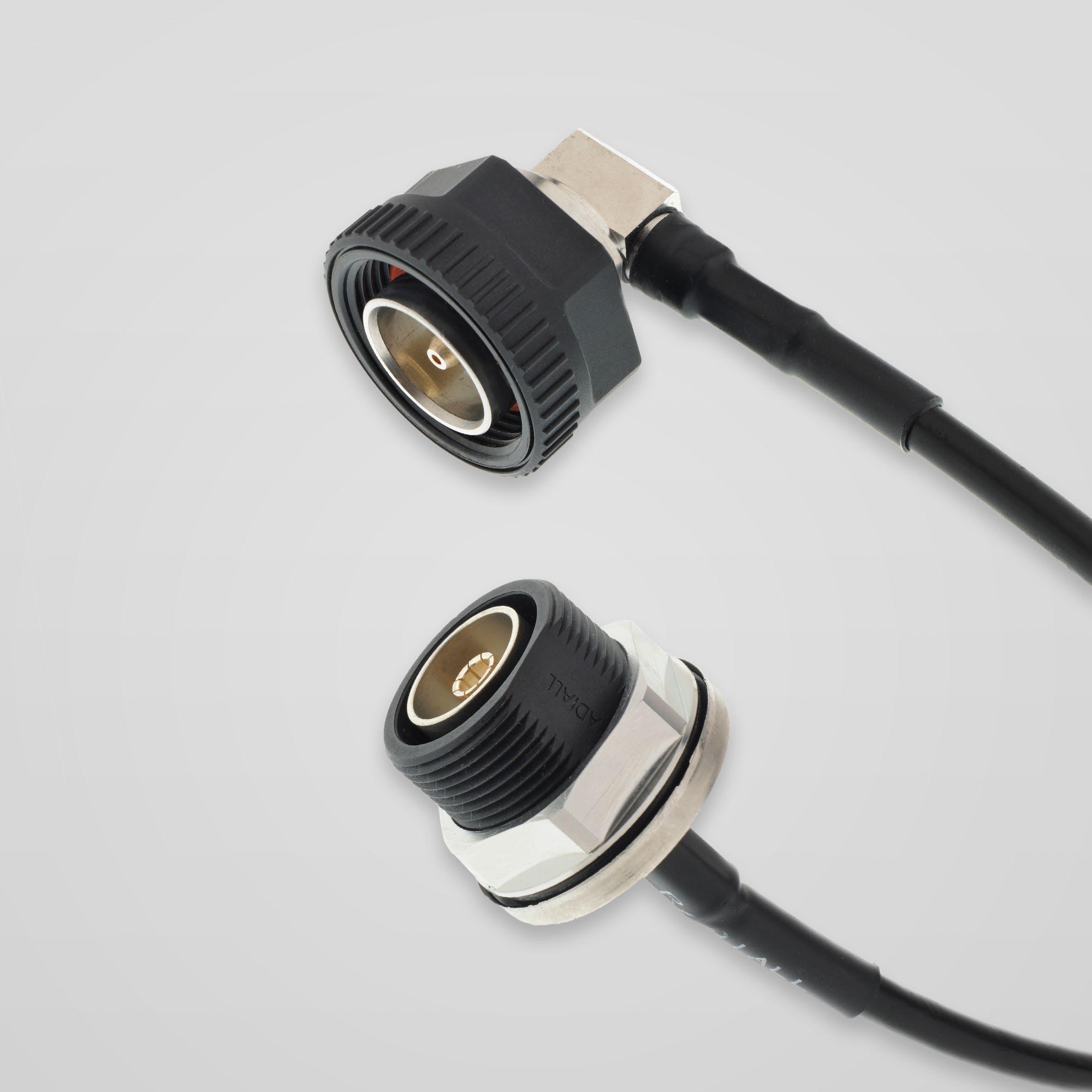
Radiall’s 7/16 series has been developed using the latest technology advances in connector design. These connectors are easy to use, highly reliable, innovative and designed to meet the needs of the telecommunications market. The complete connector series features:
• An extensive range, with optimized component part design
• An upgraded cross-knurled coupling nut allowing better manual tightening
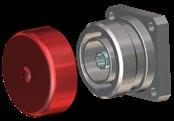
Composite 7/16
Radiall expanded its line of innovative 7/16 composite connectors with jacks and receptacles as a lightweight, low cost alternative to brass connectors. Manufactured with corrosion-proof, composite materials these new single-piece connectors are UV resistant, meeting IEC 68-2-5 and IEC-68-2-9 to withstand all environments, including harsh outdoor installations. Radiall now offers over 20 different variations. The selection of the composite materials is a result of an in-depth competitive analysis of creeping speeds of zinc and aluminum alloys. Not only do the composite materials offer considerable performance advantages guaranteeing up to 500 matings, but with more than a 50% reduction in weight, this receptacle reduces the overall weight of the final module as well as transportation costs.
5-4 Go online for data sheets & assembly instructions. Visit www.radiall.com and enter the part number. SIMPLIFICATION IS OUR INNOVATION
50Ω DC - 7.5 GHz
7/16
Introduction
Introduction
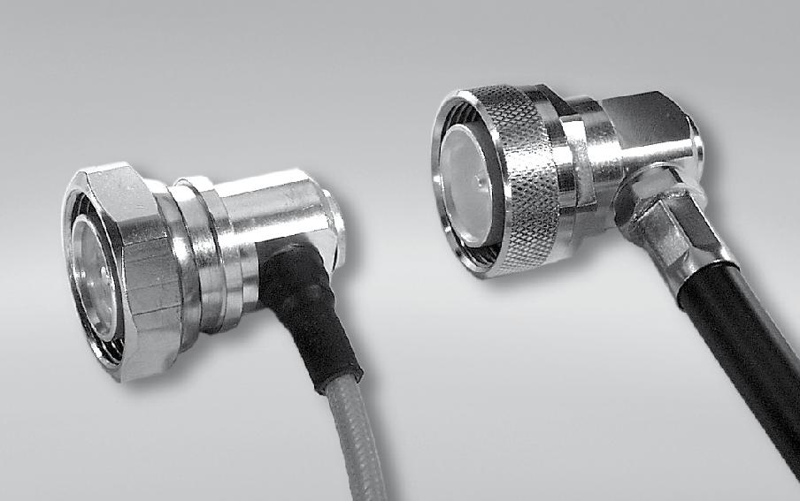
High performance range
• Frequency range: DC - 7.5 GHz
• 2 types of coupling nut:
- Cross-knurled and 6 flats 27mm wide coupling nut (3 000 N.cm)
- 6 flats coupling nut (32mm wide), allowing high coupling torque (3 500 N.cm) when used with a torque wrench
• Intermodulation performance: 2 levels
- 125 dBm cable assemblies
- 110 dBm connectors and cable assemblies
2 types of coupling nut
Radiall has developed its intermodulation measurement equipment following the IEC 46 D/292/NP standard proposal. It is aimed at third-order IMP measurements through the reflection method. The range of this test set-up is -132 dBm (-175 dBc) under 2 x 20 W.
• High performance non-magnetic material (brass) and plating (silver) with anti-tarnishing finish (strike of BBR)
• Non-slotted outer contact on standard products
• The 7/16 connector series benefits from a complete easy-to-use range of tooling
Custom models
To fulfill customer requirements, Radiall offers complete design of custom connectors according to the 7/16 series standard.
5-5 Go online for data sheets & assembly instructions. Visit www.radiall.com and enter the part number. SIMPLIFICATION IS OUR INNOVATION
7/16
Characteristics
Test / Characteristics
ELECTRICAL CHARACTERISTICS
Impedance
Straight models
RG213-RG214-RG393 .141” .250”
1/2” superflexible corrugated
3/8” superflexible corrugated 1/4” superflexible corrugated
• Right angle models
RG213-RG214-RG393
1/2” superflexible corrugated
3/8” superflexible corrugated 1/4” superflexible corrugated
Intermodulation product (IMP3)
Connectors
Home made cable assemblies
Insertion loss (dB)
Straight connectors and right-angle connectors
Leakage
Contact
•
Working voltage in VRMS at sea level
Dielectric withstanding voltage in VRMS
• At sea level (at 70, 000 feet)
MECHANICAL CHARACTERISTICS
Durability
Force to engage and disengage
Recommended coupling nut torque
• Hex. coupling nut
• Hex. + cross knurl coupling nut
Coupling nut retention force
Cable retention force
Cable 5/50 & 10/50
Cable 1/4”
Cable 3/8”
Cable 1/2”
Cable 7/8”
Center contact retention force
ENVIRONMENTAL CHARACTERISTICS
Temperature range
• Flexible cables and corrugated cables
• Semi-rigid cables
Thermo cycling test
Rapid change of temperature
High temperature test
Corrosion salt spray
Vibration
Moisture resistance
• Clamp type
• Crimp type
• Home made cable assemblies
Hermetic test
Leakage
* Contact us
(with heatshrink sleeve)
(overmolding)
5-6 Go online for data sheets & assembly instructions. Visit www.radiall.com and enter the part number. SIMPLIFICATION IS OUR INNOVATION
50Ω
range DC - 7.5 GHz Typical V.S.W.R. 1 GHz 2.5 GHz 5 GHz 7.5 GHz •
1.10 max from DC to 3 GHz - 1.20 max from 3 to 7.5 GHz
Frequency
1.04 1.04 1.03 1.02 1.03 1.01 1.06 1.07 1.05 1.04 1.03 1.02 1.08 1.08 1.11 1.05 1.12 1.09 1.10 1.20 1.13 1.05 1.20 1.17
1.15 max from DC to 3 GHz
1.02 1.04 1.05 1.02 1.04 1.04 1.08 1.06 1.12 1.14 1.12 1.13 1.50 1.60 1.80 1.60
•
-110 dBm typ. (- 153 dBc typ / 20 W) -125 dBm typ. (- 168 dBc typ. / 20 W)
•
MIL 0.05 √F (GHz) RF
CECC 130 dB at 1 GHz Insulation resistance CECC 10 000 MΩ min
resistance
Center contact • Outer contact CECC < 0.4 mΩ ≤ 1.5 mΩ
CECC 2 700
CECC 4 000 350
CECC 500 matings
CECC 15 N
3 500 Ncm (with torque wrench R 282 303 500) 3 000 Ncm (with torque wrench R 282 303 520) Proof torque CECC 3 500 Ncm
CECC 1 000 N
CECC 250 N 200 N 250 N 350 N 500 N
CECC 200 N
CECC - 55 °C + 155 °C - 55 °C + 105 °C
CECC - 55 °C / + 155 °C
56 days
/
IEC - 55 °C / + 155 °C / 5 cycles
CECC 1000 hours / 155 °C
IEC 48 hours / Na Cl 5% / 35 °C
720h
(Up to
with HEP2R)*
CECC 98 m/s2
500 Hz
- 10 Hz at
IEC
IP67 IP65
IP68
529
IEC 5 Pa.
cm3/s
CECC 1 cm3/h max
Standard
reference Values / Remarks
7/16
Characteristics
MATERIALS AND PLATINGS
Gasket
POWER RANGE
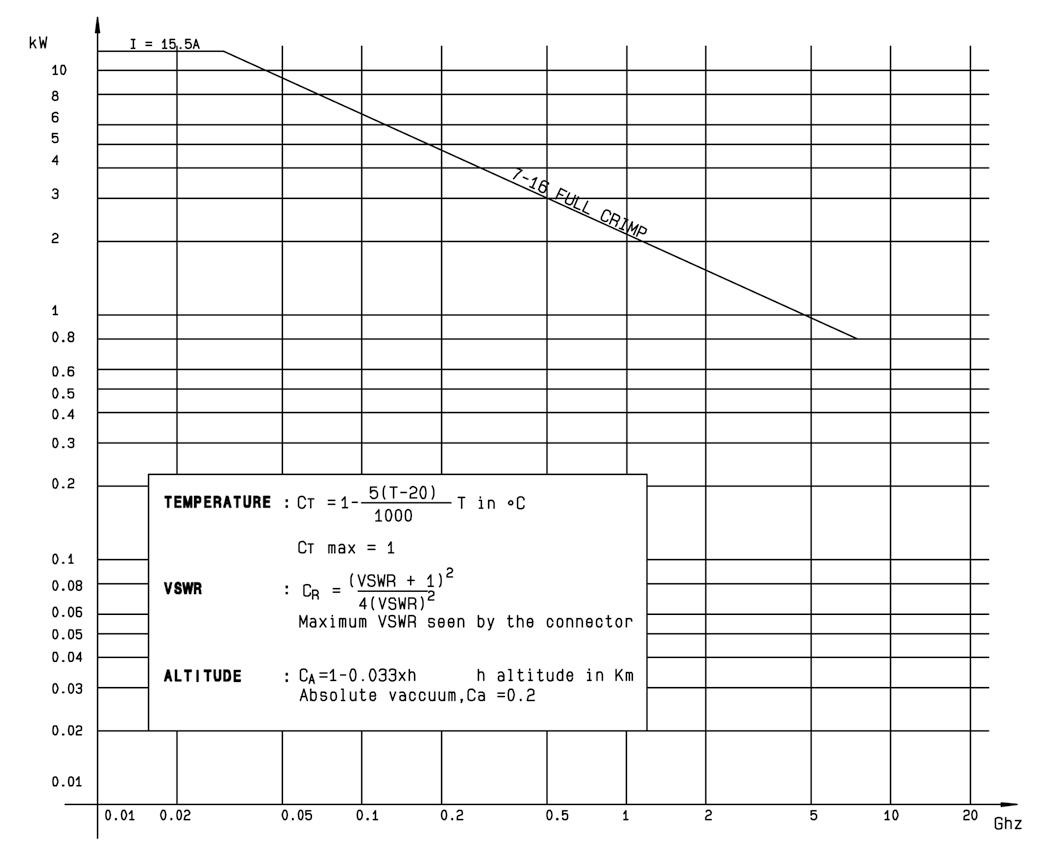
Characteristics Composite 7/16
ELECTRICAL CHARACTERISTICS
High working voltage
Very low intermodulation
< -125 dBm under 2 carriers of +43dBm And typically < -130 dBm
Power handling > 800 W@ 935 MHz
MECHANICAL CHARACTERISTICS
Longlife duration up to 500 mating cycles
Coupling torque 35 Nm or less
Coupling strength 1000 N
Center contact retention / axial force > 200 N
Center contact retention / torque > 80 Ncm
ENVIRONMENTAL CHARACTERISTICS
5-7 Go online for data sheets & assembly instructions. Visit www.radiall.com and enter the part number. SIMPLIFICATION IS OUR INNOVATION
7/16
Materials Plating Bodies Brass Silver + BBR Nut Brass BBR Center contact • Male • Female Brass Beryllium copper Silver Insulator PTFE
Silicon rubber
DC - 7.5 GHz VSWR 1.06@DC-3 GHz - 1.10@DC - 3-7.5 GHz
Frequency range
> 2700 V
IMP3
UL94-VO UV resistance IEC 68-2-5 / IEC 68-2-9
Temperature range -40°C / +85°C Humidity Up to 100% @ 20°C Flammability rating
Waterproof IP67
Plugs and Jacks
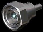
STRAIGHT PLUGS, FOR FLEXIBLE AND SEMI-RIGID CABLE

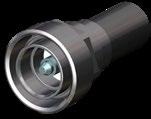
STRAIGHT JACKS
5-8 Go online for data sheets & assembly instructions. Visit www.radiall.com and enter the part number. SIMPLIFICATION IS OUR INNOVATION
Fig. 1
Fig. 2
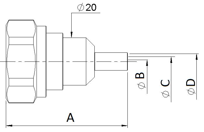
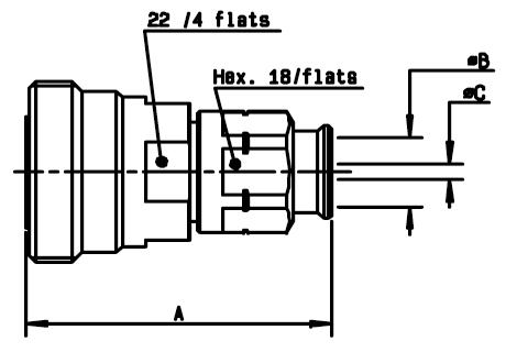
7/16 Cable group Cable group dia. Part number Fig. Dimensions (mm) Captive center contact Finish Note A B C D RG401 .250” R185 054 020 1 Silver + BBR Solder Type AEP-240FR LMR® 240 R185 083 310 2 51.15 1.5 4.05 6.6 Yes BBR Clamp type AEP-400FR LMR® 400 R185 085 007 49.55 2.82 7.46 11.05 AEP-600FR LMR® 600 R185 077 010 58.05 4.7 11.96 15.88 Cable group dia. Part number Dimensions (mm) Captive center contact Finish Note A B C 1/4” superflexible corrugated R185 215 200 49.45 7.95 4.7 Yes Silver + BBR Clamp type 1/2” superflexible corrugated R185 216 200 50 14 8.8 3/8” superflexible corrugated R185 217 200 11 7.1
Jacks
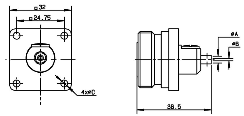
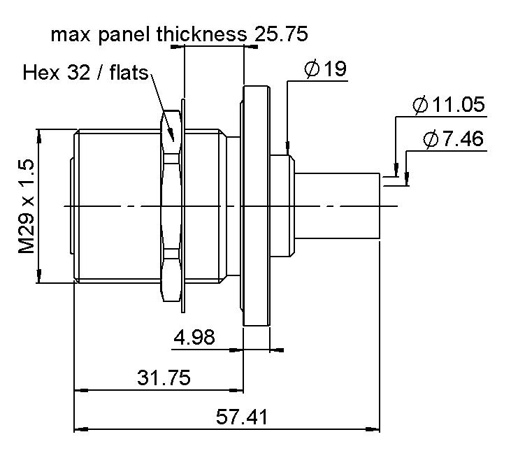
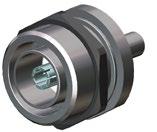
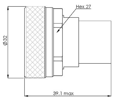
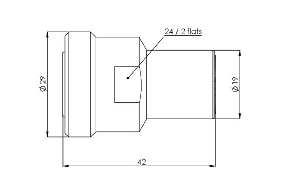
STRAIGHT SQUARE FLANGE JACK
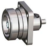
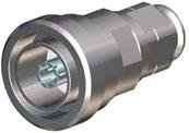
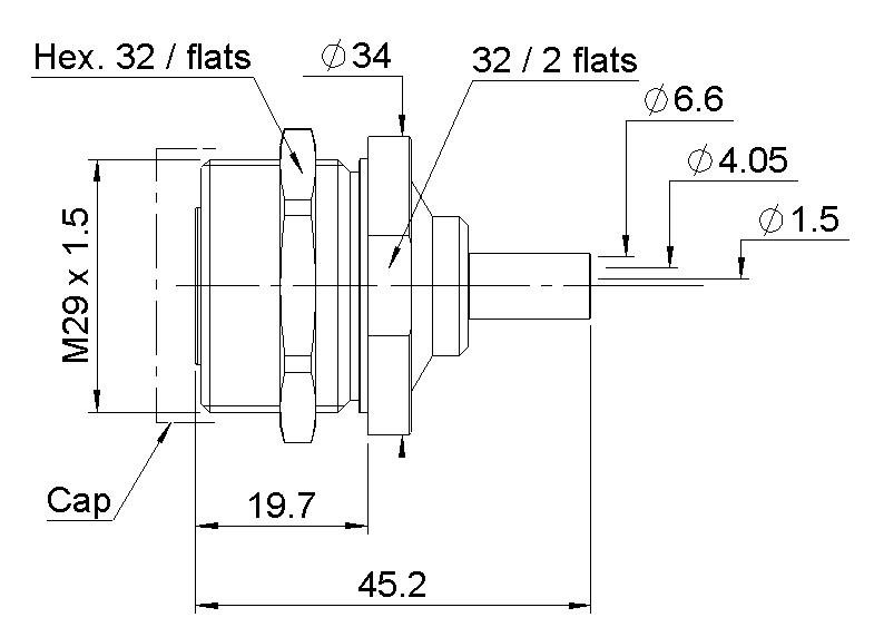
STRAIGHT BULKHEAD JACKS FOR FLEXIBLE CABLES AND CORRUGATED CABLES
5-9 Go online for data sheets & assembly instructions. Visit www.radiall.com and enter the part number. SIMPLIFICATION IS OUR INNOVATION
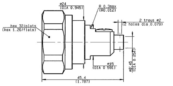
7/16 Cable group Cable group dia. Part number Captive center contact Dimensions (mm) Panel drilling Finish Note A B C RG402 .141” R185 252 000 Yes 3.65 0.996 3.6 P01 Silver + BBR Solder type for semi-rigid cables
Fig. 2
Cable group Cable group dia. Part number Fig. Captive center contact Panel drilling Finish Note AEP-240FR LMR® 240 R185 314 100 1 Yes P02 BBR Clamp type AEP-400FR LMR® 400 R185 320 020 2
Fig. 1
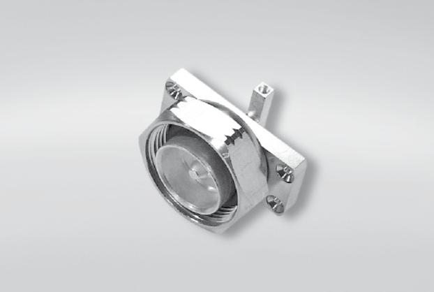
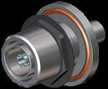
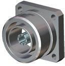
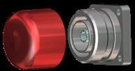
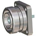
Receptacles
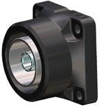
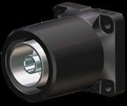
STRAIGHT FLANGE FEMALE RECEPTACLES
5-10 Go online for data sheets & assembly instructions. Visit www.radiall.com and enter the part number. SIMPLIFICATION IS OUR INNOVATION
Fig. 3
Fig. 4
Fig. 5
Fig. 2
Fig. 1
7/16 Part number Fig. Captive center contact Panel drilling Finish Slotted outer contact Packaging Note R185 403 547 1 Yes P03 BBR No 20 With solder pot contact R185 405 200 2 P05 Silver + Copper Yes Panel seal flange mount R185 406 090 3 BBR No 50 M3 R185 404 200 4 Silver + Copper 20 With slotted contact R185 403 490 5 P04 20 With tab contact
Receptacles
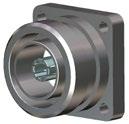
SQUARE FLANGE JACK RECEPTACLE SOLDER TYPE, PANEL SEAL
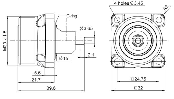
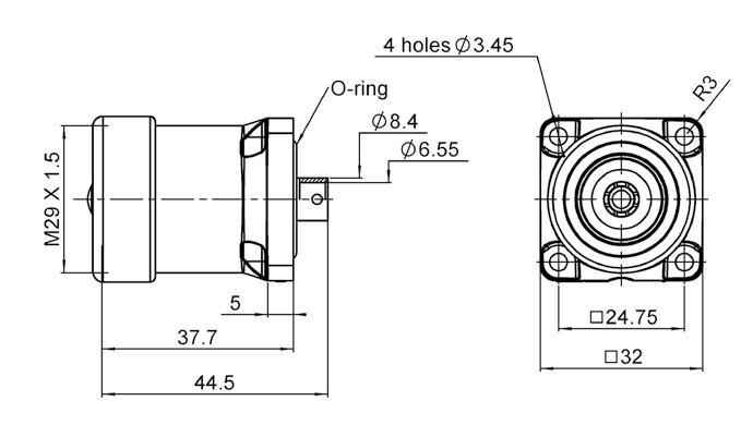
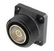
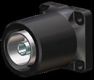
SQUARE FLANGE JACK RECEPTACLE PANEL SEAL


Available packaged in increments of 20
5-11 Go online for data sheets & assembly instructions. Visit www.radiall.com and enter the part number. SIMPLIFICATION IS OUR INNOVATION
Cable group Cable group dia. Part number Fig. Panel drilling RG402 .141" R187 403 010 1 P06 RG401 .250" R187 130 000 2
Fig. 1
Fig. 2
Part number Fig. Captive center contact Waterproof interface Color Panel drilling R187 403 000 1 No No Black P06 R187 403 100 Yes R187 406 000 Yes No R187 406 100 Yes R187 413 000 2 No No R187 413 100 Yes R187 416 000 Yes No R187 416 100 Yes
Fig. 1
Fig. 2
customer needs *
inside, only on the waterproof models 7/16
units Processed according to
O-ring
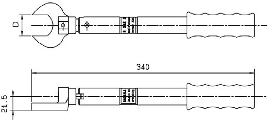
TORQUE WRENCH 32mm
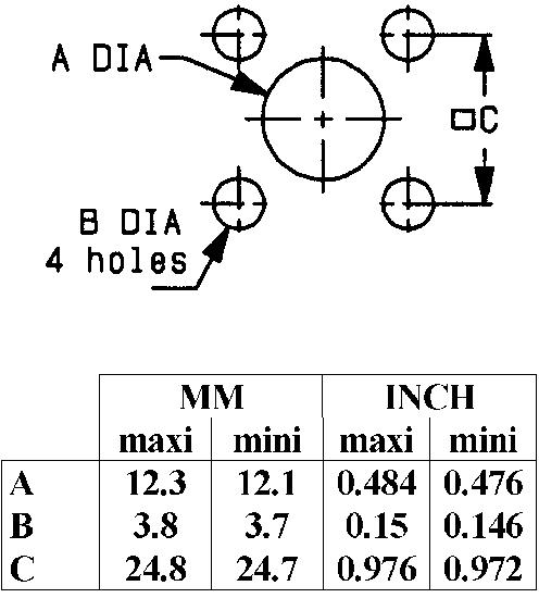
Panel Drilling
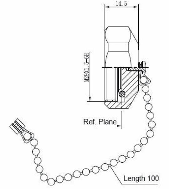
5-12 Go online for data sheets & assembly instructions. Visit www.radiall.com and enter the part number. SIMPLIFICATION IS OUR INNOVATION PROTECTIVE CAP Part Number Note R185
Male
chain Accessories
7/16
812 007
with
and Tools
P01 P04 P02 P05 P03
Part Number Accross flats D (mm) Coupling torque (N.cm) R282 303 500 32 (1.260) 3500
Low Power Terminations
Medium Power Terminations
5-13 Go online for data sheets & assembly instructions. Visit www.radiall.com and enter the part number. SIMPLIFICATION IS OUR INNOVATION
7/16
Fig. 1
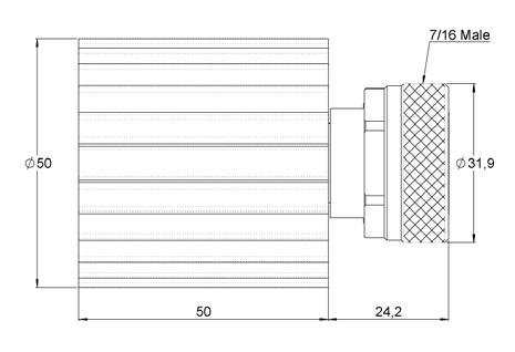
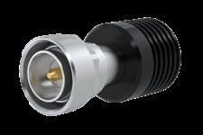
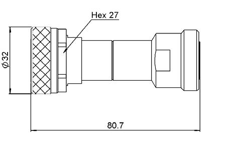
Frequency DC to (GHz) VSWR max. Return loss min. (dB) Power rating (W) Impedance (Ω) Gender Part number Fig. average peak 4 1.15 23.1 2 500 50±5% Male R404 170 111 1 Female R494 175 111 2
Fig. 2
Fig. 1
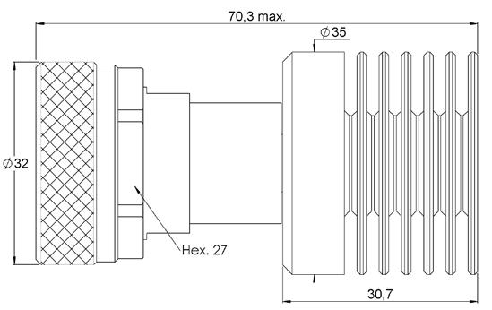
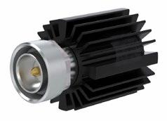
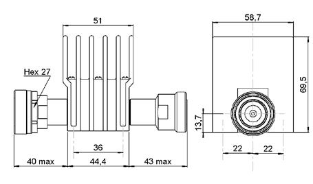
Frequency DC to (GHz) VSWR max. Return loss min. (dB) Power rating (W) Impedance (Ω) Gender Part number Fig. average peak 6 1.3 17.7 30 2,000 50±5% Male R404 756 000 1 4 1.2 20.8 12 5,000 R494 564 000 2
Fig. 2
Low Power Attenuators
Available
Medium Power Attenuators
Available attenuation value: xx- 03, 06, 10 and 20 dB. (1) ±0,6 for xx = 20
5-14 Go online for data sheets & assembly instructions. Visit www.radiall.com and enter the part number. SIMPLIFICATION IS OUR INNOVATION
Frequency DC to (GHz) VSWR max. Return loss min. (dB) Power rating (W) Nom. Attenuation (dB) Max dev. Part number average peak 3 1.3 17.7 1 100 xx ±0,5(1) R412 806 000
attenuation value: xx- 03, 06, 10 and 20 dB. (1) ±1 for xx = 20
Frequency DC to (GHz) VSWR max. Return loss min. (dB) Power rating (W) Nom. Attenuation (dB) Max dev. Part number average peak 4 1.35 16.5 25 5,000 xx ±0,6(1) R420 303 110
7/16