4.3-10
Introduction
GENERAL
• Low Intermodulation connector
• Screw-on & push-pull coupling mechanism
• High power rating
• 30% smaller & 60% lighter than 7/16
APPLICABLE STANDARDS
• IEC 61169
• MIL PRF 39012
APPLICATIONS
• Telecom
• Medical
• Industrial
• Indoor and outdoor use
Overview
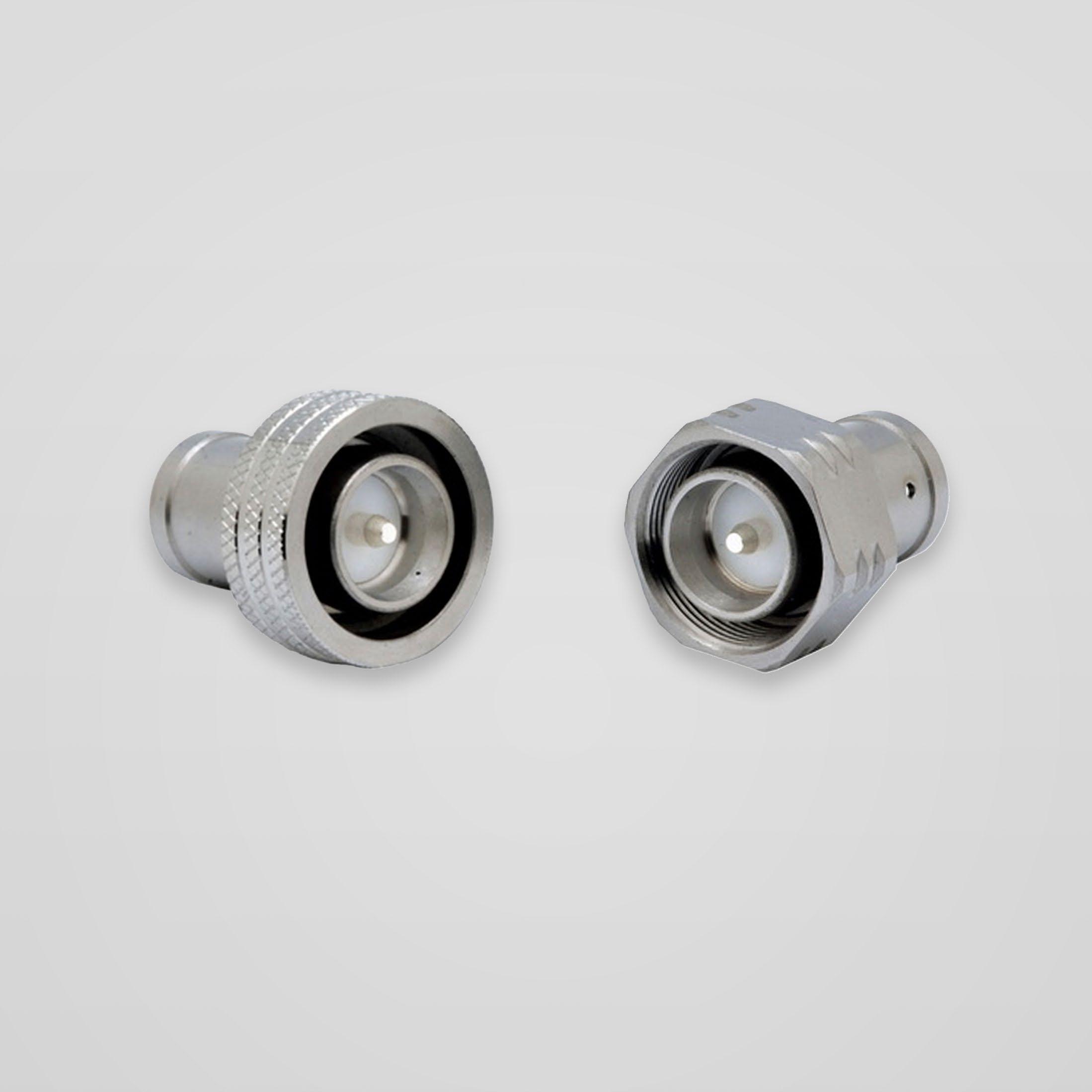
Designed for major telecom equipment manufacturers, the 4.3-10 series offers a small, lightweight solution for outdoor telecom applications where high performance is essential and low intermodulation is required.
Radiall's broad product portfolio includes the 4.3-10, 4.1-9.5, 7/16 and the innovative QLI (Quick Lock Low Intermodulation) connector. These solutions are suitable for harsh environments where reliability is required.
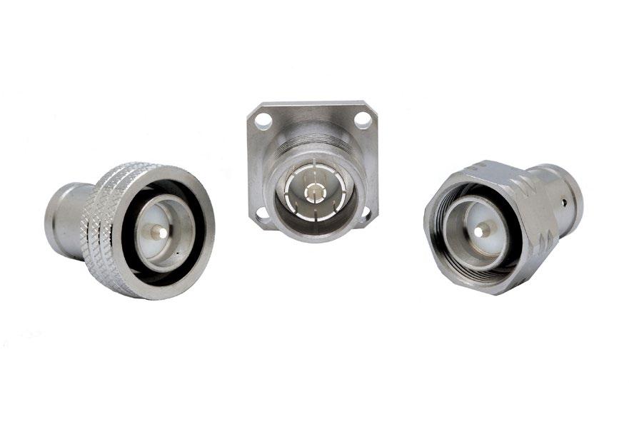
Available in a variety of configurations including:
- Jack/Bulkhead
- Square flange receptacles and plugs
- Right angle models
- Solder, crimp and clamp models
- Screw-on and push-pull coupling mechanism
4.3-10 connectors are a lightweight solution and are 30% smaller and 60% lighter than comparable 7/16 square flange jack receptacles. The new interface features a high intermodulation level ranging from 0-6 GHz and provides a low intermodulation level at <-166dBc.
Radiall's 4.3-10 connector solution is designed in accordance with international standards and manufactured to meet environmental safety requirements.
HIGH PERFORMANCE
• Impedance 50Ω
• Frequency range DC ~ 6 GHz
• Very low intermodulation level <-166dBc
• Screw-on and push-pull coupling mechanism for safety and ease of use
• VSWR 1.04 + 0.01 √f
• Meets all requirements for IP67
• High mating life
• 3 step connection: Engage, Push & Lock
• Intuitive design concept
• Lightweight
• Reduced size allows more space for other components
• RF Power: Up to 500 W @ 2 GHz
2-4 Go online for data sheets & assembly instructions. Visit www.radiall.com and enter the part number. SIMPLIFICATION IS OUR INNOVATION
50Ω DC - 6 GHz
Characteristics
Test / Characteristics
ELECTRICAL CHARACTERISTICS
Values / Remarks
Impedance 50Ω
Frequency range
Typical VSWR
DC - 6 GHz
1.04 + 0.01 f (GHz)
Maximum insertion loss 0.05 √F (GHz) dB
Insulation resistance
5000 MΩ min
Voltage rating <=1000 Veff
Dielectric withstanding voltage >2500 Veff
Contact resistance
• Center contact
• Outer contact
Power
< 1 mΩ < 1.5 mΩ
500W @ 2 GHz
Intermodulation <165dBc (>120 dBm) 2x20W
Typical RF leakage -110dB@3 GHz; -100dB@3~6 GHz
MECHANICAL CHARACTERISTICS
Mechanical endurance 100 cycles
Mating force (push-pull version)
• Engagement force for mating
• Separation force for mating
Mating torque (tool screw type)
• Torque
Mating mechanical retention force 450 N min.
Cable retention force 350 N mini with 1/2" S cable
Vibration
ENVIRONMENTAL CHARACTERISTICS
Temperature range - 55 °C ~ + 90 °C
Moisture resistance IP67
Corrosion salt spray
MATERIALS
Connector bodies Brass
Male center contact Bronze / Brass
Female center contact Bronze
Outer contact Brass
Other metallic parts Brass
Insulators PTFE
PLATING
Bodies BBR
Outer contact BBR
Center contact Silver
* Contact us
61169-1 § 9.3.3
2-5 Go online for data sheets & assembly instructions. Visit www.radiall.com and enter the part number. SIMPLIFICATION IS OUR INNOVATION
4.3-10
<=100 N <=80 N IEC
§9.3.6
61169-1
IEC
5 N. m
61169-1 §9.3.6
10g
IEC
2 Hz to 200 Hz
48h Up to 720
HEP2R*
with
Plugs
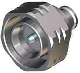
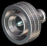
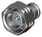
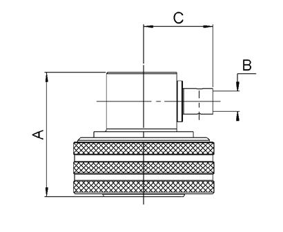
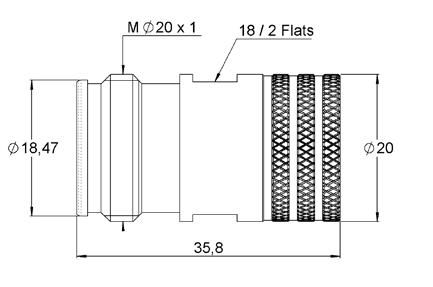
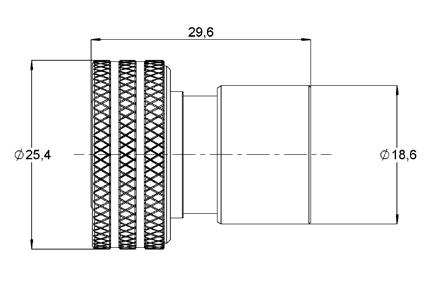
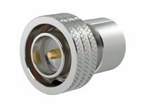
STRAIGHT PLUG FOR FLEXIBLE AND SEMI-RIGID CABLE
RG402 / KS2 / BELDEN 1673A / HC90000(3) / SUCOFORM 141
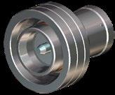
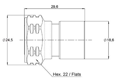
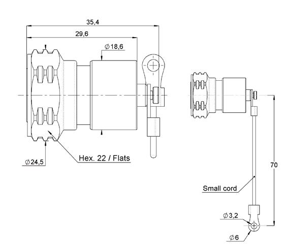
STRAIGHT PLUGS FOR CORRUGATED CABLES
2-6 Go online for data sheets & assembly instructions. Visit www.radiall.com and enter the part number. SIMPLIFICATION IS OUR INNOVATION
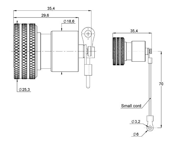
Cable group dia. Part number Fig. Dimensions Captive center contact Finish Coupling mechanism Note A B C 1/2" superflexible corrugated R183 031 007 1 27.9 3.80 12.55 Yes Silver + BBR Screw-on Solder R183 031 017 2 Push-pull 1/4" superflexible corrugated R183 030 017 1 23.8 2 6.8 Screw-on R183 030 007 2 Push-pull 3/8" superflexible corrugated R183 032 007 1 25.9 2.8 9.45 Screw-on Cable group Cable group dia. Part number Dimensions Captive center contact Finish Coupling mechanism Note A B C
.141 R183 052 007 21.9 0.96 3.7 Yes Silver + BBR Push-pull Solder
Fig. 1
4.3-10
Fig. 2
Plugs
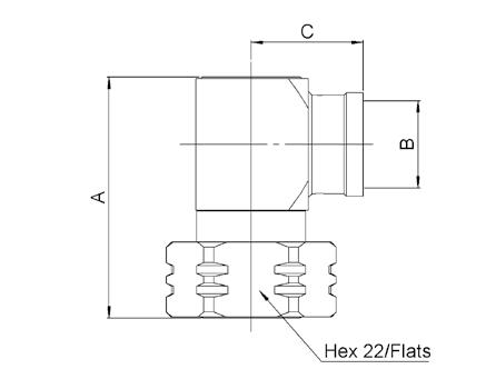
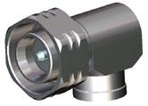
RIGHT ANGLE PLUG FOR HANDFORMABLE AND SEMI-RIGID CABLES
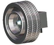
RIGHT ANGLE PLUG FOR CORRUGATED CABLES
Jacks
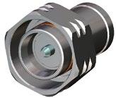
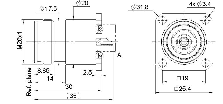
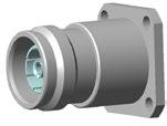
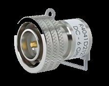
STRAIGHT SQUARE FLANGE JACKS
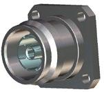
SQUARE FLANGE JACK RECEPTACLES
2-7 Go online for data sheets & assembly instructions. Visit www.radiall.com and enter the part number. SIMPLIFICATION IS OUR INNOVATION
Cable group Cable group dia. Part number Dimensions Captive center contact Finish Coupling mechanism Note A B C RG402 / KS2 .141 R183 197 007 21.7 3.65 12.5 Yes Silver + BBR Push-pull Solder
Cable group dia. Part number Dimensions Captive center contact Finish Coupling mechanism Note A B C 1/2"
R183 165 007 34.7 12.55 16.15 Yes Silver + BBR Screw-on Solder 4.3-10
superflexible corrugated
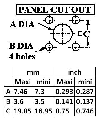
Cable group Cable group dia. Part number Captive center contact Panel drilling Finish RG402 .141 R183 252 007 Yes P01 Silver / BBR
Part number Captive center contact Panel drilling Finish Note R183 405 067 Yes P02 Silver / BBR Solder pot

2-8 Go online for data sheets & assembly instructions. Visit www.radiall.com and enter the part number. SIMPLIFICATION IS OUR INNOVATION 4.3-10 Accessories
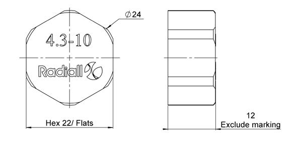
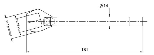
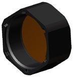
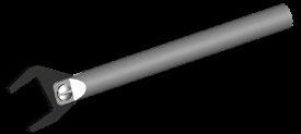
Tools Part number Note R183 804 020 IP67 for mated condition UV resistance R282 303 240 Torque wrench 5N.m P01
P02
and
Panel Drilling
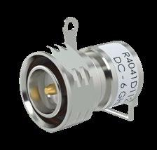
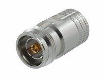
Low Power Terminations
2-9 Go online for data sheets & assembly instructions. Visit www.radiall.com and enter the part number. SIMPLIFICATION IS OUR INNOVATION
Fig. 1
Fig. 2
Fig. 3
Fig. 4
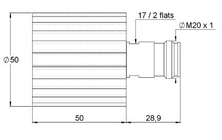
Frequency DC to (GHz) VSWR max. Return loss min. (dB) Power rating (W) Impedance (Ω) Gender Part number Fig. average peak 6 1.25 19.1 2 500 50±5% Male screw R404 1D1 000 1 R404 1D1 121(1) 2 Male push-pull R404 1D2 000 3 R404 1D2 121(1) 4 Female R404 1D5 000 5
Fig. 5
4.3-10
(1) with cord
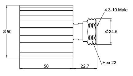
Medium Power Terminations
1 Fig. 2
Medium Power Attenuators
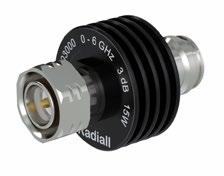
Available attenuation value: xx = 03, 06,10, 20 dB
2-10 Go online for data sheets & assembly instructions. Visit www.radiall.com and enter the part number. SIMPLIFICATION IS OUR INNOVATION
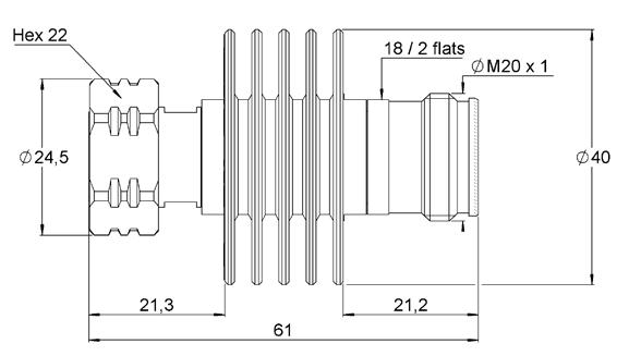
Frequency DC to (GHz) VSWR max. Return loss min. (dB) Power rating (W) Impedance (Ω) Gender Part number Fig. average peak 6 1.3 17.7 30 2,000 50±5% Male screw R404 758 000 1 Female R404 759 000 2
Fig.
Frequency DC to (GHz) VSWR max. Return loss min. (dB) Power rating (W) Nom. Attenuation (dB) Max dev. Part number average peak 6 1.15 14.0 15 250 xx ±0.6 R415 6xx 000
4.3-10