
HIGH FREQUENCY CONNECTORS: N 18 GHZ
R163/R143/R127/R327
Section 10 Table of Contents
INTRODUCTION
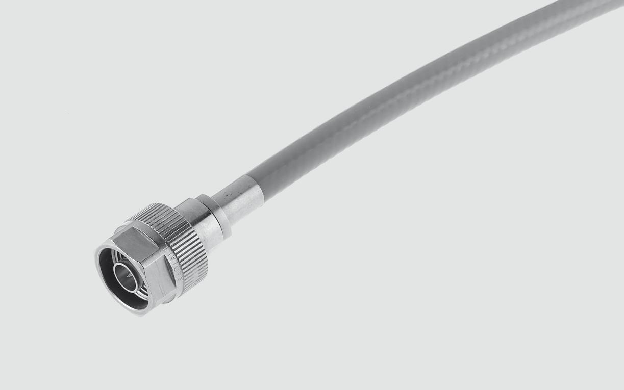
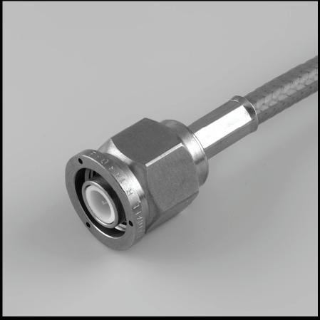
N 18 connectors are 50 ohm precision N Type connectors designed to perform through 18 GHz� N connectors are a popular medium sized option commonly used in microwave and RF applications that require high power handling and good electrical performance Radiall Type N connector interfaces utilizes a PTFE (Teflon) dielectric. The male connectors are provided with a 19 mm (3/4 in.) hex coupling nut so they can be properly torqued.
Connector bodies are made from stainless steel, and contacts are made from gold plated and heat treated beryllium copper contacts to insure long life and reliability.
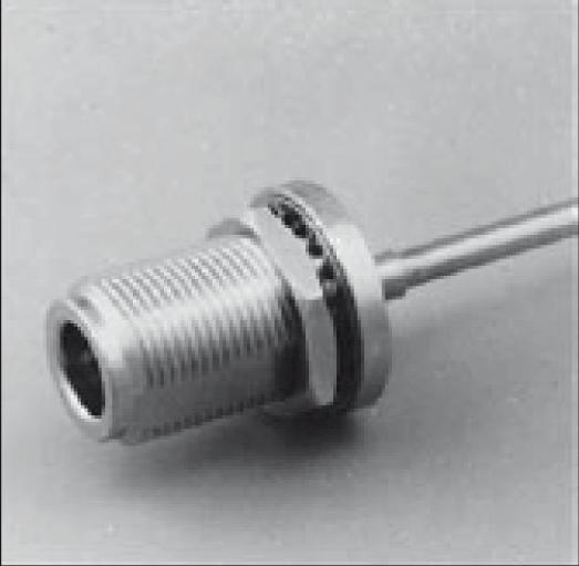
Radiall offers N connectors for semi-rigid and low loss flexible cables, receptacles and precision adapters.
Connectors for low loss flexible cables and TestPro cables are not detailed in this section. They are available in our cable assembly offer.
TYPE N 18 DESIGN FEATURES
• Excellent performance up to 18 GHz
• Low VSWR and insertion loss
• Highly robust construction for reliability
• Superior interface environmental seal
• High power capability

INTERFACE
IMPORTANT:
CHARACTERISTICS
TEST / CHARACTERISTICS
ELECTRICAL CHARACTERISTICS
Impedance
Typical V.S.W.R. • Straight Connector
• Right Angle Connector
Insertion Loss
Contact Resistance • Outer Contact
Inner Contact
Power (At Sea Level)
Average Power (At Sea Level, 25 °C)
Dielectric
VALUES / REMARKS
(2 to 3 GHz)
MECHANICAL CHARACTERISTICS
Coupling Torque
Ncm (14 Ibf.in) Contact Captivation
ENVIRONMENTAL CHARACTERISTICS
Vibration
Shock
Thermal Shock
Corrosion (Salt Mist)
High Temperature Test
Damp Heat
Low Pressure Immersion
Resistance to Fluids Contamination
MATERIALS
Ncm (6 Ibf) min
MIL-STD-1344 Method 2005 Condition 4
MIL-STD-1344 Method 2004 Condition G
MIL-STD-1344 Method 1003 Condition A
MIL-STD-1344 Method 1001 Condition B
CECC 22000/4 7 2
CECC 22000/4 �6 �6
EN2591 AECMA TestC14
EN2591 AECMA TestC15
Body Stainless Steel
Center Contact
PLATING
Beryllium Copper and Brass
Coupling Nut Brass
Insulator
PTFE or Polyetherimid Resin Gasket
Fluorosilicon or Fluorocarbon
Body Passivated
Center Contact Gold
Coupling Nut Nickel

CABLE GROUP CABLE GROUP DIA. PART NUMBER CAPTIVE CENTER CONTACT MATERIAL NOTE
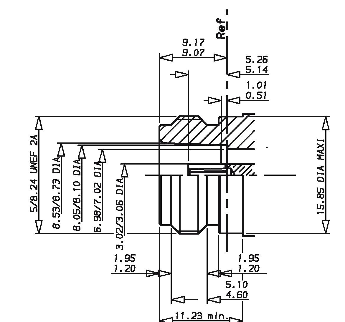
RG402 141" 4000-1563-009 Yes Stainless Steel Direct Solder
RG405 085" 4000-1563-010
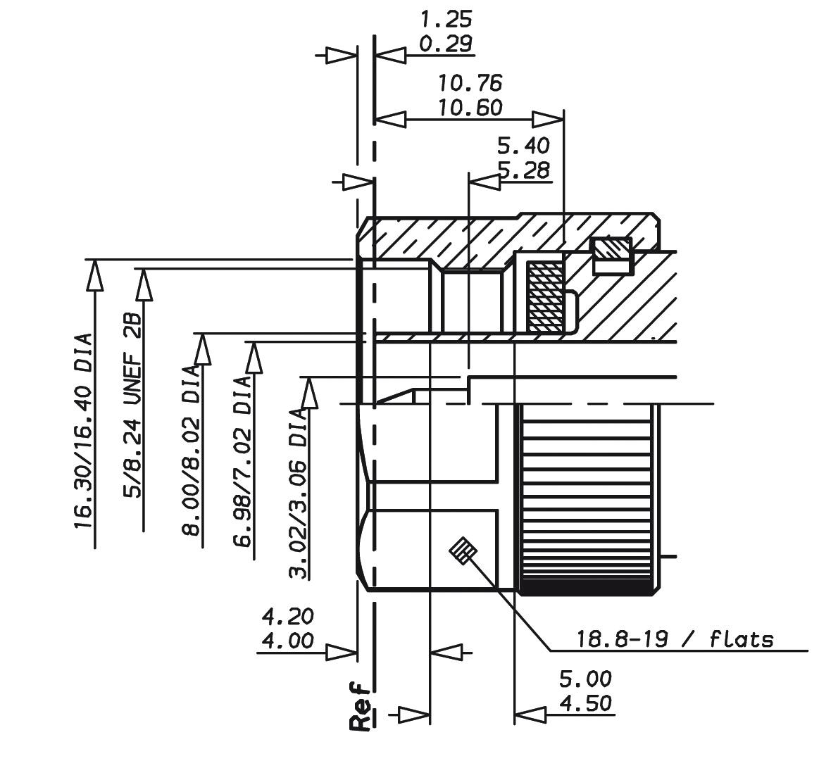
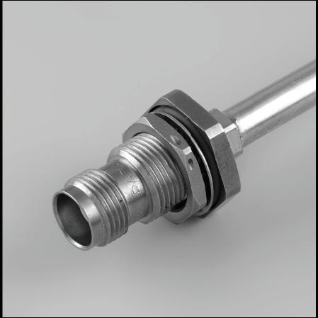
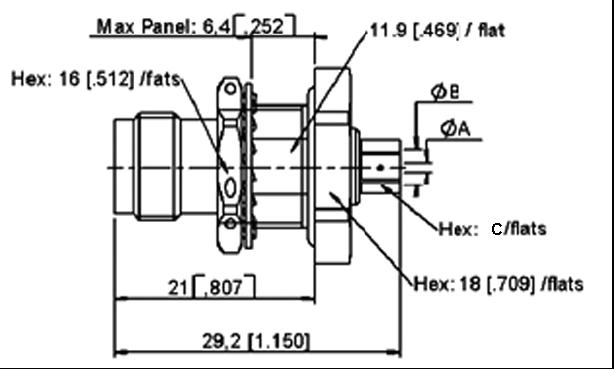
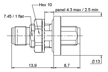
BULKHEAD STRAIGHT JACKS, FOR SEMI-RIGID CABLES (PANEL SEALED)
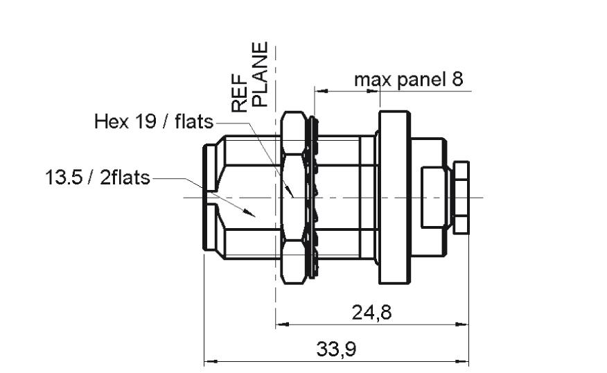
CABLE GROUP CABLE GROUP DIA. PART NUMBER CAPTIVE CENTER CONTACT PANEL DRILLING MATERIAL NOTE
RG405 085" 4501-9543-010 Yes P14 Stainless Steel Solder Clamp / Rear Mount
RG402 141" 4501-9543-009 R163 337 001
IN SERIES ADAPTERS [2]
Notes
1. N18 GHz plugs for SHF high frequency flexible cable are available as cable assemblies only. Consult us for standard N18 GHz cable assembly part numbers. 2. 7mm air line adapters also available upon request.
TNC 18 GHz
INTRODUCTION
TNC 18 connectors are 50 ohm precision TNC Type connectors designed to perform through 18 GHz TNC connectors are a popular medium sized option commonly used in microwave and RF applications that require average power handling and good electrical performance. Radiall TNC connector interfaces utilizes a PTFE (Teflon) dielectric. The male connectors are provided with a 14 mm (9/16 in.) hex coupling nut so they can be properly torqued. Connector bodies are made from stainless steel, and contacts are made from gold plated and heat treated beryllium copper contacts to insure long life and reliability.
Radiall offers TNC connectors for semi-rigid and low loss flexible cables, receptacles and precision adapters
Connectors for low loss flexible cables and TestPro cables are not detailed in this section. They are available in ourcable assembly offer.
INTERFACE
TNC 18 DESIGN FEATURES
• Excellent performance up to 18 GHz
• Low VSWR and insertion loss
• Rugged construction for reliability
• Superior interface environmental seal
• Medium power capability
CHARACTERISTICS
TEST / CHARACTERISTICS
ELECTRICAL CHARACTERISTICS Impedance
MECHANICAL CHARACTERISTICS
Recommended Mating Torque
MIL-C-39012 A
VALUES / REMARKS
Axial Force: Not Applicable Torque: 1.96 inch pounds (22.6 N.cm)
inch pounds (265 N.cm) Proof Torque
Coupling Mechanism Retention
29.40 inch pounds (339 N.cm)
Lbf (227 N min) (cable dia. .189 (4.8) to .228 (5.8))
Lbf (340 N min) (cable dia. .250 (6.35) and above)
Center Contact Retention - Axial: 6.06 Lbf (27 N)
ENVIRONMENTAL CHARACTERISTICS
Temperature Range
• Standard Models
• Hermetic Sealed Models
• Models for Semi-Rigid Cables
Combined Climate Tests
Thermal Shock 3-20
High Temperature Endurance
Corrosion (Salt Spray) 3-13
Vibrations 3-18
Shocks 3-19
Moisture Resistance 3-21
MIL-STD-202, Method 107, Condition B
MIL-STD-202, Method 108
MIL-STD-202, Method 101, Condition B
MIL-STD-202, Method 204, Condition B
MIL-STD-202, Method 213, Condition G
MIL-STD-202, Method 106
Low Pressure 3-22 Not Applicable
Hermetic Seal
MATERIALS
Applied Vacuum 10 -6 mm of Hg (Torrs) Leakage Rate < 10 -6 atm/cm 3/s
Leakage - Pressure 3.5 bars; Duration 2 mn; Temperature 15 °C to 25 °C
Body - Stainless Steel
Center Socket Contact
• Male
• Female - Brass Bronze
Ferrules - Brass
Insulators
Gaskets
PLATING
PTFE Teflon
Silicone Elastomer
Body - Passivated
Center Contacts
Gold Plated
PLUGS AND JACKS
STRAIGHT PLUGS CRIMP TYPE FOR FLEXIBLE CABLE
/ RG223 / RG400 5/50/D
/ RG225 11/50/D
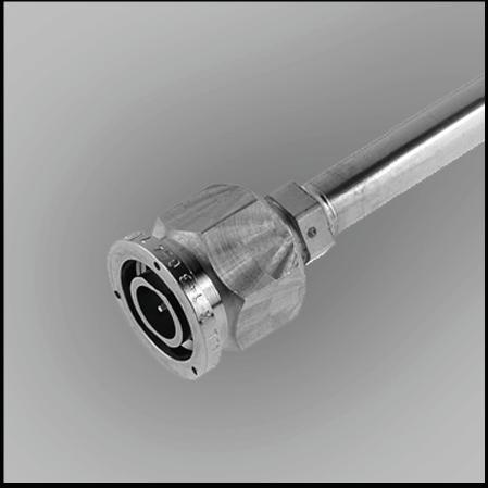
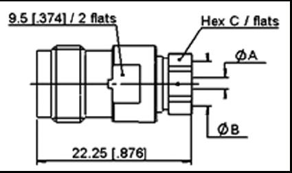
STRAIGHT PLUGS SOLDER TYPE FOR SEMI-RIGID CABLE
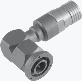
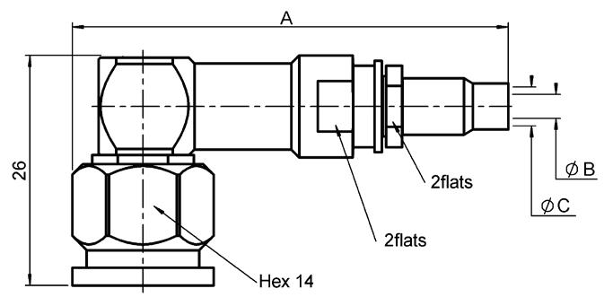
RIGHT ANGLE PLUGS CRIMP TYPE FOR FLEXIBLE CABLE
Notes Standard packaging = unit All dimensions are given in mm (inch)
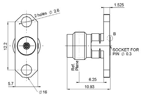
STRAIGHT JACK SOLDER TYPE FOR SEMI-RIGID CABLE

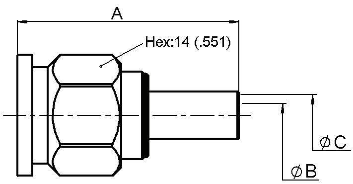
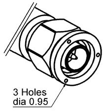
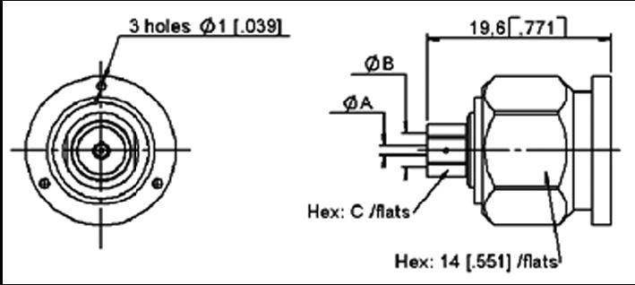
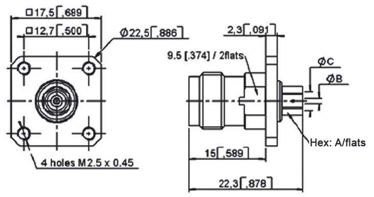
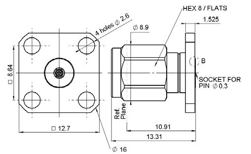
STRAIGHT SQUARE FLANGE JACK CRIMP TYPE FOR FLEXIBLE CABLE

1
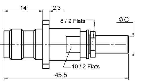
FIG. 2

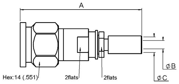
STRAIGHT SQUARE FLANGE JACKS SOLDER TYPE FOR SEMI-RIGID CABLE
JACKS AND RECEPTACLES
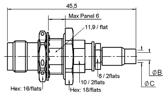
STRAIGHT BULKHEAD JACK PANEL SEALED
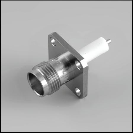
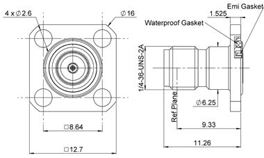
SQUARE FLANGE STRAIGHT FEMALE RECEPTACLE (EXTENDED DIELECTRIC)

ADAPTERS AND CAPS IN SERIES ADAPTERS


INTRODUCTION
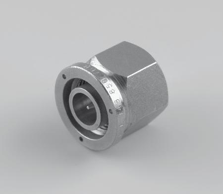
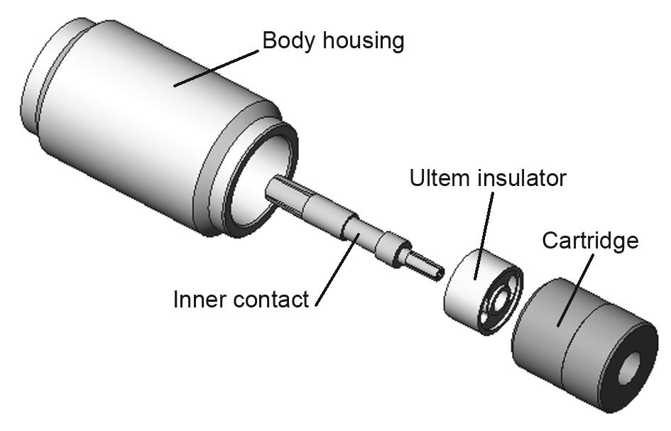
SMA 2.9 series is compatible with K® series, 2 92 mm, SMA and SMA 3 5 series, and has a shortened male center contact, ensuring a non destructive mating. Radiall offers four product variations for SMA 2.9 to meet all your needs with two different designs. The standard design is using our “ULTEM” insulator technology and is qualified up to 40 GHz. The high frequency design is using our “KAPTON” insulator technology and is qualified up to 46 GHz. All versions feature the same electrical high performance and are available in a variety of configurations.
SMA 2.9 FOR GENERAL USE, “ULTEM” TECHNOLOGY, DC-40 GHZ
This robust design is suitable for most applications. The ULTEM insulator provides a high ingress protection level against chemicals, fluids or dust and is well suited for high frequency aerospace and military equipment.
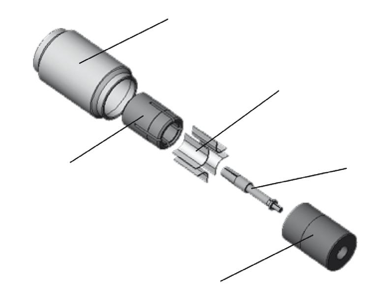
SMA 2.9 FOR TEST LABORATORY USE, “KAPTON” TECHNOLOGY, DC-46 GHZ
The KAPTON insulator design is excellent for high frequency measurements in test laboratories. KAPTON is also very stable with temperature. Radiall SMA 2.9 adapters using KAPTON are specified DC-46 GHz and operate within a large temperature range - 65 °C/+200 °C�
SMA 2.9 FOR SPACE APPLICATIONS
Radiall is a certified manufacturer of connectors for space applications according to ESA specifications. A range of space qualified SMA 2.9 connectors using the ULTEM insulator technology is available. Please consult us.
SMA 2.9 FOR HARSH ENVIRONMENTS
Radiall also offers a range of cable assemblies equipped with specific connectors for applications in harsh environment. The connectors are made of high grade stainless steel 316L ultra resistant to corrosion and wear� Please consult us�
INTERFACE
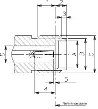
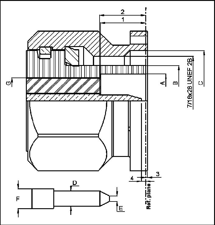
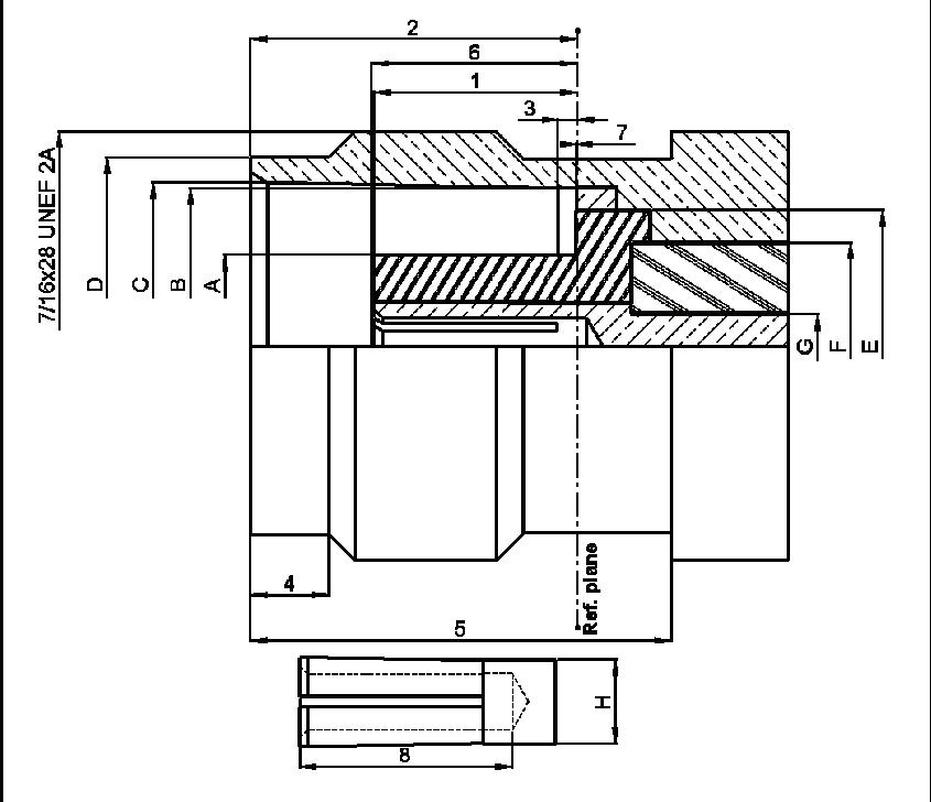
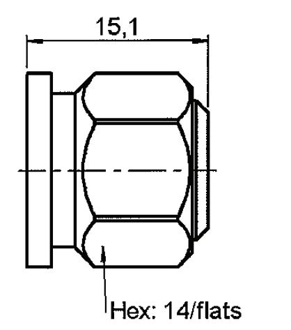
LETTER OR FIGURE MM INCH
1 2 87 3 27 113 129
2 1 88 1 98 074 078
3 0�65 0�95 �026 �037
4 2 40 2 68 094 105
5 - 0 08 - 003
A 4 �60 4 �63 �181 �182
B 5 30 5 35 209 211
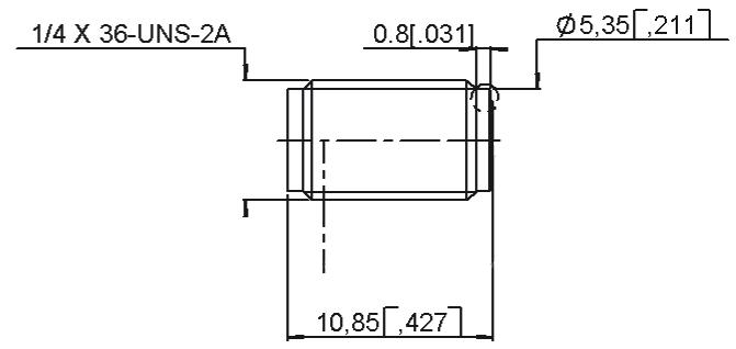
C 1/4 - 36 UNS 2A
D 2 90 2 94 114 116
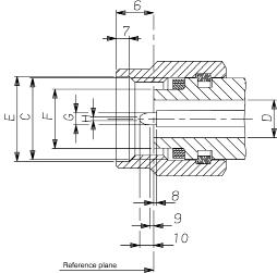
OR FIGURE
6 2 63 3 25 103 128 7 0 90 1 10 35 043
8 - 0�08 - �003
9 0 49 0 78 019 031 10 1 22 1 40 048 055 C 1/4 - 36 UNS 2B D 2 90 2 94 114 116 E 6 60 6 70 260 264 F 4 55 4 58 179 180 G 0 92 0 94 036 037 H 0 20 0 34 008 013
CHARACTERISTICS
TEST / CHARACTERISTICS
ELECTRICAL CHARACTERISTICS
Impedance
Frequency Range
VALUES / REMARKS
ULTEM TECHNOLOGY KAPTON TECHNOLOGY
V.S.W.R. < 1.05 + 0.005 F (GHz)
Insertion Loss 0.03 √ F (GHz)
RF Leakage – 90 dB max
Insulation Resistance
Contact Resistance
• Outer Contact
• Inner Contact
Voltage Rating
Dielectric Withstanding Voltage
MECHANICAL CHARACTERISTICS
Mechanical Endurance
5000 MΩ
2 mΩ
≤ 3 mΩ
≤ 7 mΩ
V(RMS)
V(RMS)
500 Matings Force to Engage and Disengage
≤ 23 N cm (2 in/lbs)
Mating Torque 80 to 115 N cm (7 to 10 in/lbs)
Coupling Nut Retention Force ≤ 272 N (61 lbf)
Cable Retention Force
• .085" • .141"
N (30 lbf)
N (60 lbf)
Contact Captivation 28N (6.3 lbf)
ENVIRONMENTAL CHARACTERISTICS
Temperature Range
-65 °C / + 165 °C
-65 °C / +200 °C
Thermal Shock MIL STD 202, Method 107, Condition B
High Temperature Test MIL STD 202, Method 108
Corrosion (Salt Spray)
MIL STD 202, Method 101, Condition B, 5 %
Vibration MIL STD 202, Method 204, Condition D, 20g Shock MIL STD 202, Method 213, Condition I, 100g
Moisture Resistance MIL STD 202, Method 106
MATERIALS AND PLATING
Bodies
Center Contacts
Gasket
Material
Plating
Stainless Steel Passivated
Beryllium Copper Gold Plated
Silicone RubberInsulators
Ultem (Ultem Technology) Kapton (Kapton Technology) -
Notes
Packaging: unit
All dimensions are given in mm (inch)
PLUGS
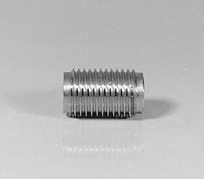
STRAIGHT PLUGS, SOLDER TYPE FOR MICROPOROUS SEMI-RIGID CABLES
JACKS AND RECEPTACLES
STRAIGHT JACK SOLDER TYPE FOR MICROPOROUS SEMI-RIGID CABLES
UNIVERSAL SCREW-ON FEMALE RECEPTACLES
FLANGE FEMALE RECEPTACLES
R127 840 021 1 ULTEM
N/A With Cylindrical Center Contact R127 842 001 2
R127 631 001 KAPTONR127 632 001 3
R127 842 101 4 PEEK
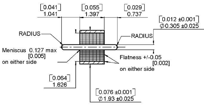
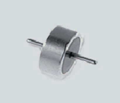
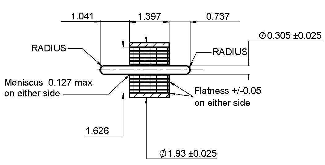
GLASS BEAD AND IN SERIES ADAPTERS
(.012)
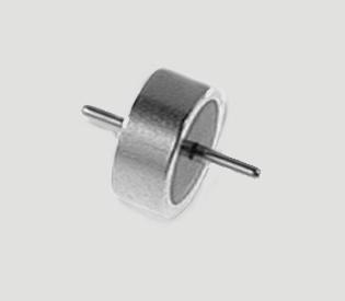
GLASS BEAD IN SERIES ADAPTERS

R127 703 001 2
R127 704 001 3
R127 705 001 1
R127 712 001 4 Female - Female - 4 Hole Flange
R127 732 100 5
R127 753 000 5
R127 870 001 1
R127 872 001 3
R127 871 001 2
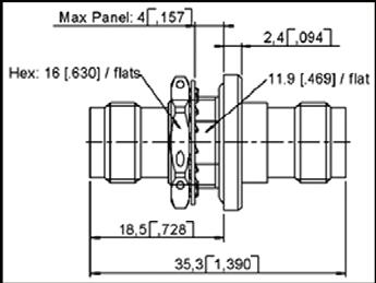
Female - Female - Bulkhead Panel Sealed
Female - Female - Bulkhead Hermetic
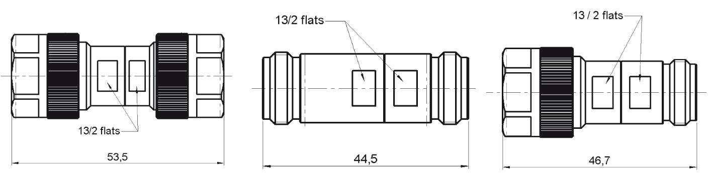
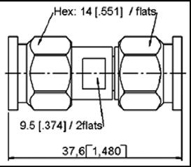
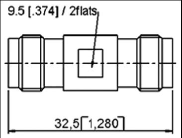
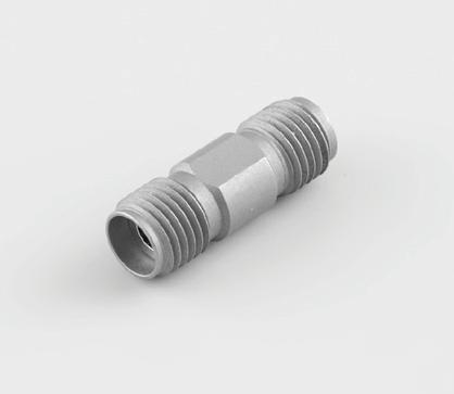
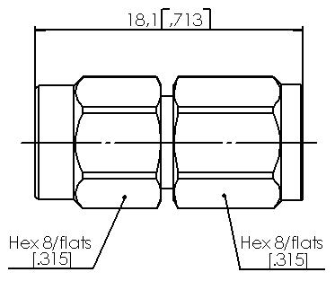
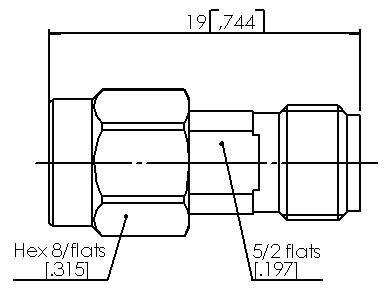
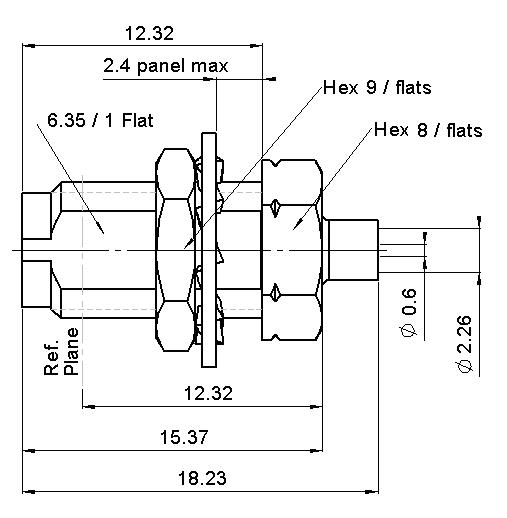
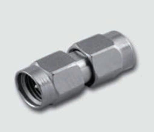
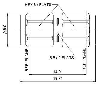
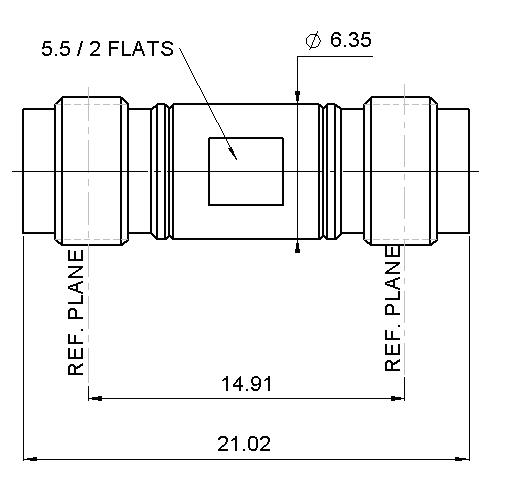
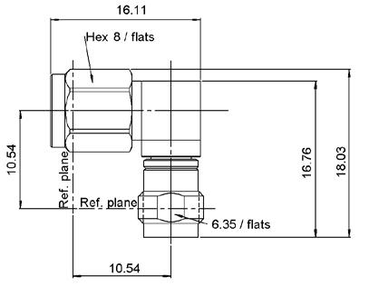
BETWEEN SERIES ADAPTERS BETWEEN SERIES ADAPTERS [1]

970 061 1
970 071 2
970 081 3
970 091 4
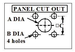
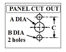
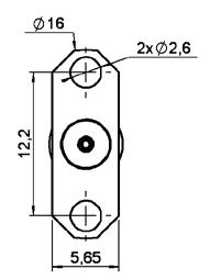
PANEL DRILLING
mminc h maximinimaximini
A1.631.6 0.064.063
B2.702.6 0.106.102
A2.952.91.116.115
B2.72.6.106.102
C8.698.59.342.338
C8.698.5 9.342.338 mminch maximinimaximini
Notes 1. These adapters are still using the previous technology (4 kapton strips) allowing to reach 46 GHz within a temperature range of – 65 °C/+ 200 °C.
2.4 MM
INTRODUCTION
2 4 mm connectors are 50 ohm precision connectors designed for use to 50 GHz The design eliminates the fragility of the SMA and 2.92 mm connectors by increasing the outer wall thickness and strengthening the female fingers. The outer conductor measures 2.4 mm and the robust wall of the connector body is designed to engage before the center conductor, assuring a rugged, repeatable mating interface. The male connectors are provided with a 8 mm (5/16 in.) hex coupling nut so they can be properly torqued.
2.4 mm connectors are mechanically compatible with 1.85 mm connectors. They cannot mate with SMA, 3.5-mm and 2�92-mm without the use of precision adapters�
Radiall offers 2.4 mm connectors for semi-rigid and low loss flexible cables, receptacles, and precision adapters
Connectors for low loss flexible cables and TestPro cables are not detailed in this section. They are available in our cable assembly offer.
INTERFACE


2.4 MM DESIGN FEATURES
• Excellent performance up to 50 GHz
• Low VSWR and insertion loss
• Rugged construction for reliability
• Mechanically compatible with 1�85 mm connector series
2.4 MM
CHARACTERISTICS
TEST / CHARACTERISTICS
ELECTRICAL CHARACTERISTICS
VALUES / REMARKS
Impedance 50Ω
Frequency Range
V.S.W.R.
DC - 50 GHz
< 1.05 + 0.003 F (GHz)
Insertion Loss 0.04 √ F (GHz)
RF Leakage – 100 dB max
Insulation Resistance
• Contact Resistance <= 1400Veff > 5000 mΩ
Contact Resistance
• Outer Conductor
• Inner Conductor < 0.8 mΩ < 4 mΩ
Voltage Rating 250 V(RMS)
Dielectric Withstanding Voltage 500 V(RMS)
MECHANICAL CHARACTERISTICS
Mechanical Endurance 500 Matings Force to Engage and Disengage < 23 N cm
Mating Torque 90 N cm
Coupling Nut Retention Force < 272 N
Cable Retention Force
• Outer Conductor
• Inner Conductor 130 N
Contact Captivation 27N
ENVIRONMENTAL CHARACTERISTICS
Temperature Range -65 °C / + 165 °C
Thermal Shock
High Temperature Test
Corrosion (Salt Spray)
MIL STD 202, Method 107, Condition B, -65 °C / + 165 °C
MIL STD 202, Method 108, Condition D, 1000 H at 150 °C
MIL STD 202, Method 101, Condition B, 48 H / 35 °C / 5 %
Vibration MIL STD 202, Method 204, Condition H, 30g RMS Shock MIL STD 202, Method 213, Condition I, 100g
Moisture Resistance
MATERIALS AND PLATING
Bodies
MIL STD 202, Method 106, 80% / 100% 25 °C / 65 °C 10 Cycles
Material
Plating
Beryllium Copper Cu2 5 Au0 8
Outer Contact (Body Insert) Brass Cu2 � 5 Au0� 8
Center Contacts
Coupling Nut
Gaskets
Beryllium Copper Ni2 Au1 3
Stainless Steel Passivated
Silicone RubberInsulators PEEK -
2.4 MM
PLUGS, JACKS AND RECEPTACLES
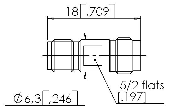
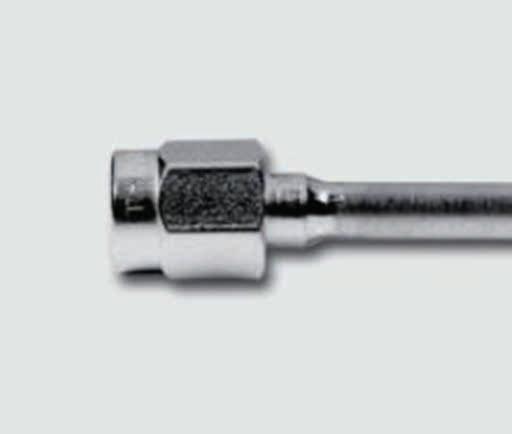
STRAIGHT PLUGS, SOLDER TYPE FOR SEMI-RIGID CABLES
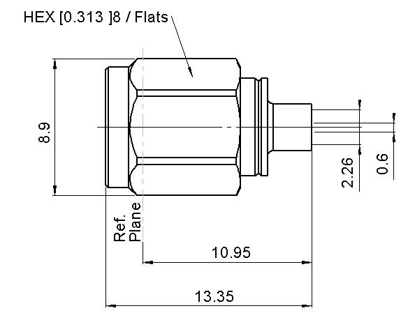
CABLE GROUP CABLE GROUP DIA. PART NUMBER
RG405 085"
CENTER CONTACT
R327 052 000 Yes RG405 085" Microporous R327 052 202
STRAIGHT JACKS, SOLDER TYPE FOR SEMI-RIGID CABLES

CABLE GROUP CABLE GROUP DIA. FIG.
RG405 085" 1
R327 222 000 Yes �085" Microporous
R327 222 200 085" 2
R327 316 000 085" Microporous
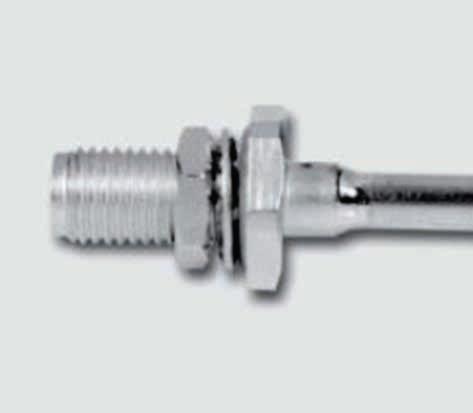
UNIVERSAL SCREW-ON FEMALE RECEPTACLES
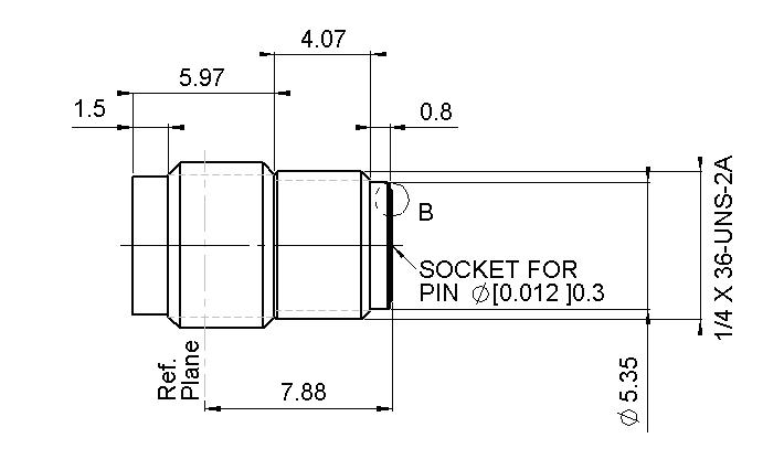
R327 316 010
2.4 MM
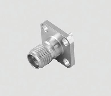
FLANGE RECEPTACLES
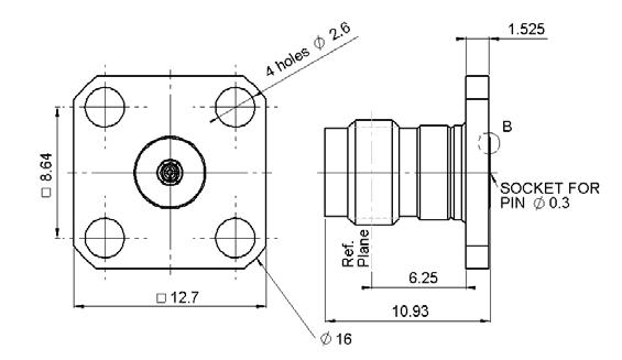
411 000 2
465 000 3
2.4 MM
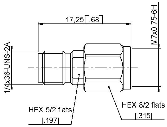
IN SERIES ADAPTERS AND PANEL DRILLING IN SERIES ADAPTERS

DRILLING